WO2021181439A1 - Teaching data creation system, teaching data creation method, and teaching data creation program - Google Patents
Teaching data creation system, teaching data creation method, and teaching data creation program Download PDFInfo
- Publication number
- WO2021181439A1 WO2021181439A1 PCT/JP2020/009909 JP2020009909W WO2021181439A1 WO 2021181439 A1 WO2021181439 A1 WO 2021181439A1 JP 2020009909 W JP2020009909 W JP 2020009909W WO 2021181439 A1 WO2021181439 A1 WO 2021181439A1
- Authority
- WO
- WIPO (PCT)
- Prior art keywords
- image
- unit
- information
- teacher
- representative
- Prior art date
Links
Images


Classifications
-
- G—PHYSICS
- G06—COMPUTING; CALCULATING OR COUNTING
- G06V—IMAGE OR VIDEO RECOGNITION OR UNDERSTANDING
- G06V10/00—Arrangements for image or video recognition or understanding
- G06V10/70—Arrangements for image or video recognition or understanding using pattern recognition or machine learning
- G06V10/77—Processing image or video features in feature spaces; using data integration or data reduction, e.g. principal component analysis [PCA] or independent component analysis [ICA] or self-organising maps [SOM]; Blind source separation
- G06V10/774—Generating sets of training patterns; Bootstrap methods, e.g. bagging or boosting
-
- A—HUMAN NECESSITIES
- A61—MEDICAL OR VETERINARY SCIENCE; HYGIENE
- A61B—DIAGNOSIS; SURGERY; IDENTIFICATION
- A61B1/00—Instruments for performing medical examinations of the interior of cavities or tubes of the body by visual or photographical inspection, e.g. endoscopes; Illuminating arrangements therefor
- A61B1/04—Instruments for performing medical examinations of the interior of cavities or tubes of the body by visual or photographical inspection, e.g. endoscopes; Illuminating arrangements therefor combined with photographic or television appliances
- A61B1/045—Control thereof
-
- A—HUMAN NECESSITIES
- A61—MEDICAL OR VETERINARY SCIENCE; HYGIENE
- A61B—DIAGNOSIS; SURGERY; IDENTIFICATION
- A61B5/00—Measuring for diagnostic purposes; Identification of persons
-
- G—PHYSICS
- G06—COMPUTING; CALCULATING OR COUNTING
- G06T—IMAGE DATA PROCESSING OR GENERATION, IN GENERAL
- G06T11/00—2D [Two Dimensional] image generation
-
- G—PHYSICS
- G06—COMPUTING; CALCULATING OR COUNTING
- G06T—IMAGE DATA PROCESSING OR GENERATION, IN GENERAL
- G06T7/00—Image analysis
- G06T7/0002—Inspection of images, e.g. flaw detection
- G06T7/0012—Biomedical image inspection
-
- G—PHYSICS
- G06—COMPUTING; CALCULATING OR COUNTING
- G06V—IMAGE OR VIDEO RECOGNITION OR UNDERSTANDING
- G06V10/00—Arrangements for image or video recognition or understanding
- G06V10/70—Arrangements for image or video recognition or understanding using pattern recognition or machine learning
- G06V10/77—Processing image or video features in feature spaces; using data integration or data reduction, e.g. principal component analysis [PCA] or independent component analysis [ICA] or self-organising maps [SOM]; Blind source separation
- G06V10/772—Determining representative reference patterns, e.g. averaging or distorting patterns; Generating dictionaries
-
- G—PHYSICS
- G06—COMPUTING; CALCULATING OR COUNTING
- G06V—IMAGE OR VIDEO RECOGNITION OR UNDERSTANDING
- G06V2201/00—Indexing scheme relating to image or video recognition or understanding
- G06V2201/03—Recognition of patterns in medical or anatomical images
Definitions
- the present invention relates to a teacher data creation system, a teacher data creation method, a teacher data creation program, and the like.
- Machine learning such as deep learning is widely used as an image recognition technology.
- machine learning it is necessary to input a large number of teacher images suitable for learning, and one of the methods for preparing the large number of teacher images is data augmentation.
- Data augmentation is a method of increasing the number of teacher images by processing the actually captured original image to generate a new image.
- Patent Document 1 discloses a medical image generator that generates an image for machine learning of an ultrasonic diagnostic apparatus.
- the medical image generator sets a medical image displayed when the user performs an image saving operation or a freeze operation as a attention image, and a plurality of images similar to the attention image from a time-series image. Is mechanically extracted.
- the user gives label information to the image of interest.
- the medical image generation device adds label information to a plurality of images similar to the attention image based on the label information attached to the attention image.
- Patent Document 1 since the image when the user performs the image saving operation or the freeze operation is the image of interest, the image has low similarity to the time-series image or has high similarity among the time-series images. An image with a small number may be a noteworthy image. In this case, there is a problem that the medical image generator cannot add the label information to the time-series image using the label information given to the image of interest, or the number of images to which the medical image generator can give the label information is small. be. For example, when an image taken when the camera angle is temporarily changed significantly in an endoscope or the like becomes a noteworthy image, label information based on similarity is used for images taken at other angles. It may not be possible to grant.
- an image acquisition unit that acquires a plurality of medical images and medical images included in the plurality of medical images are associated with each other based on the similarity of imaging targets, and the medical images that can be associated with each other are associated with each other.
- An image mapping unit that creates a group of associated images composed of And, based on the input receiving unit that accepts the input of the representative teacher information and the representative teacher information input to the image to be given, the teacher information is given to the medical image included in the associated image group. It is related to the teacher information addition department and the teacher data creation system including.
- a plurality of medical images are acquired, and the medical images included in the plurality of medical images are associated with each other based on the similarity of the imaging target, and the medical images that can be associated with each other are associated with each other.
- Creating a group of associated images that constitute a group outputting the image to be assigned, which is an image to be assigned the representative teacher information, to the display unit based on the associated image group, and the representative teacher information.
- Teacher data including accepting the input of and adding teacher information to the medical image included in the associated image group based on the representative teacher information input to the image to be given. It is related to the creation method.
- a plurality of medical images are acquired, and the medical images included in the plurality of medical images are associated with each other based on the similarity of the imaging target, and the medical images that can be associated with each other are associated with each other.
- Creating a group of associated images composed of The computer is instructed to accept the input of information and to give teacher information to the medical image included in the associated image group based on the representative teacher information input to the image to be given. It is related to the teacher data creation program to be executed.
- the first configuration example of the teacher data creation system The flowchart of the process in the 1st configuration example.
- the figure explaining the operation of the image correspondence part The figure explaining the determination method of the correspondence image group.
- the flowchart of the process in the 1st modification of the 1st configuration example An example of an image displayed on the display unit in the second modification of the first configuration example.
- the flowchart of the process in the 3rd modification of the 1st configuration example A configuration example of the teacher data creation system in the fourth modification of the first configuration example.
- the figure explaining the 2nd operation example of the input adjustment part The flowchart of the process in the 2nd configuration example.
- the figure explaining the operation of the image correspondence part The figure explaining the operation of an image output part, an input reception part, and a teacher information addition part.
- the figure explaining the 2nd modification of the 2nd configuration example The flowchart of the process in the 3rd modification of the 2nd configuration example.
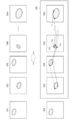
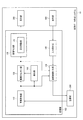
- FIG. 1 is a first configuration example of the teacher data creation system 10.
- the teacher data creation system 10 includes a processing unit 100, a storage unit 200, a display unit 300, and an operation unit 400.
- the endoscope 600 and the learning device 500 are also shown in FIG. 1, when the teacher data creating system 10 creates teacher data, the endoscope 600 and the learning device 500 are connected to the teacher data creating system 10. You don't have to be.
- the processing unit 100 includes an image acquisition unit 110, an image association unit 120, an image output unit 130, a teacher information addition unit 150, an input reception unit 140, and a teacher information addition unit 150.
- the image acquisition unit 110 acquires a plurality of medical images.
- the image mapping unit 120 creates a group of associated images by associating medical images included in a plurality of medical images based on the similarity of imaging targets.
- the associated image group is a group composed of medical images that can be associated with each other in the above association.
- the image output unit 130 outputs to the display unit 300 an image to be given, which is an image to be given the representative teacher information, based on the associated image group.
- the input reception unit 140 receives input of representative teacher information from the operation unit 400.
- the teacher information giving unit 150 gives teacher information to the medical image included in the associated image group based on the representative teacher information input to the image to be given.
- the image to be given to be displayed on the display unit 300 in order to have the user give teacher information is displayed based on the associated image group that is associated based on the similarity of the shooting target.
- the image to be given is an image having similarity to each medical image in the associated image group.
- the representative teacher information is attached to the medical images associated with many images having high similarity, so that the teacher information assigning unit 150 transfers the teacher information from one representative teacher information to more medical images. Can be granted automatically.
- the number of images to be given that the user should input the representative teacher information can be reduced, and the user can create the teacher image with less work man-hours.
- the teacher data creation system 10 is an information processing device such as a PC (Personal Computer).
- the teacher data creation system 10 may be a system in which the terminal device and the information processing device are connected by a network.
- the terminal device includes a display unit 300, an operation unit 400, and a storage unit 200, and an information processing device includes a processing unit 100.
- the teacher data creation system 10 may be a cloud system in which a plurality of information processing devices are connected by a network.
- the storage unit 200 stores a plurality of medical images captured by the endoscope 600.
- a medical image is an in-vivo image taken by a medical endoscope.
- the medical endoscope is a videoscope such as an endoscope for gastrointestinal tract, a rigid scope for surgery, or the like.
- the plurality of medical images are time series images.
- the endoscope 600 captures a moving image inside the body, and the image of each frame of the moving image corresponds to an individual medical image.
- the storage unit 200 is a storage device such as a semiconductor memory or a hard disk drive.
- the semiconductor memory is, for example, a volatile memory such as RAM or a non-volatile memory such as EEPROM.
- the processing unit 100 is a processor.
- the processor may be an integrated circuit device such as a CPU, a microcomputer, a DSP, an ASIC (Application Specific Integrated Circuit) or an FPGA (Field Programmable Gate Array).
- the processing unit 100 may include one or more processors.
- the processing unit 100 which is a processor may be, for example, a processing circuit or a processing device composed of one or a plurality of circuit components, or a circuit device in which one or a plurality of circuit components are mounted on a substrate. There may be.
- the operation of the processing unit 100 may be realized by software processing. That is, the storage unit 200 is a program that describes all or part of the operations of the image acquisition unit 110, the image association unit 120, the image output unit 130, the input reception unit 140, and the teacher information addition unit 150 included in the processing unit 100. Is remembered in. When the processor executes the program stored in the storage unit 200, the operation of the processing unit 100 is realized. The program may further describe the detection unit 160, which will be described later in FIG.
- the program may be stored in an information storage medium, which is a medium that can be read by a computer.
- the information storage medium can be realized by, for example, an optical disk, a memory card, an HDD, a semiconductor memory, or the like.
- a computer is a device including an input device, a processing unit, a storage unit, and an output unit.
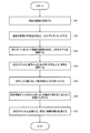
- FIG. 2 is a flowchart of processing in the first configuration example.
- the image acquisition unit 110 acquires a plurality of medical images.
- the image acquisition unit 110 is an access control unit that reads data from the storage unit 200, acquires a plurality of medical images from the storage unit 200, and outputs the plurality of medical images to the image matching unit 120. ..
- step S2 the image association unit 120 extracts feature points of a plurality of medical images and performs matching between the images for each feature point.
- step S3 the image association unit 120 selects a medical image having a large number of matched feature points, and the image output unit 130 outputs the selected medical image to the display unit 300 as an image to be given.
- the display unit 300 displays the image to be given.
- the display unit 300 is, for example, a display such as a liquid crystal display device or an EL (Electro Luminescence) display device.
- step S4 the input receiving unit 140 receives the teacher information input for the displayed image to be given. That is, the user adds teacher information to the image to be given displayed on the display unit 300 by using the operation unit 400, and the given teacher information is input to the input reception unit 140.
- the input receiving unit 140 is, for example, a communication interface between the operation unit 400 and the processing unit 100.
- the operation unit 400 is a device for a user to input an operation or information to the teacher data creation system 10, and is, for example, a pointing device, a keyboard, a touch panel, or the like.
- step S5 the teacher information giving unit 150 gives teacher information to each medical image associated with the image matching unit 120 based on the teacher information given to the image to be given, and applies the teacher information. It is stored in the storage unit 200. A medical image to which teacher information is added is called a teacher image.
- the teacher image stored in the storage unit 200 is input to the learning device 500.
- the learning device 500 includes a storage unit 520 and a processor 510.
- the teacher image input from the storage unit 200 is stored in the storage unit 520 as teacher data 521.
- a learning model 522 for machine learning is stored in the storage unit 520.
- Processor 510 uses the teacher data 521 to perform machine learning on the learning model 522.
- the machine-learned learning model 522 is transferred to the endoscope as a trained model and used for image recognition in the endoscope.
- FIG. 3 is a diagram illustrating the operation of the image associating unit 120.
- IA1 to IAm are a plurality of medical images acquired by the image acquisition unit 110.
- m is an integer of 3 or more.
- a feature point is a point indicating a feature of an image, and is a point characterized by a feature amount detected from the image.
- Various features can be assumed, such as image edges, gradients, or their statistics.
- the image mapping unit 120 extracts feature points by using a method such as SIFT (Scale Invariant Feature Transform), SURF (Speeded-Up Robust Features), and HOG (Histograms of Oriented Gradients).
- the image association unit 120 sets an image group having high similarity of the imaging target as the associated image group GIM.
- the “similarity of the imaged object” is the degree to which the objects shown in the medical image are similar, and the higher the similarity, the higher the possibility that the objects are the same.
- the image association unit 120 associates, for example, a medical image in which the number of common feature points is equal to or greater than a threshold value. In the example of FIG.
- the image associating unit 120 associates a medical image having two or more feature points in common, and IA4 has two or more feature points in common for each of IA2, IA3, and IAm. Therefore, IA2 to IA4 and IAm are designated as the associated image group GIM.
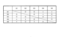
- FIG. 4 is a diagram illustrating a method for determining the associated image group.
- IX1 to IX5 are acquired as a plurality of medical images.
- the image association unit 120 determines the similarity of each medical image of IX1 to IX5 with other medical images. ⁇ indicates that the similarity was judged to be high, and ⁇ indicates that the similarity was judged to be low.
- IX1, IX2, IX3, IX4, and IX5 are judged to have high similarity to two, three, three, two, and two medical images, respectively.
- the image matching unit 120 selects a medical image having many highly similar medical images as the image to be given, and sets the medical image having high similarity to the image to be given as the associated image group.
- IX2 is selected as the image to be given, and IX1 to IX3 and IX5 are set in the associated image group.
- IX3 is selected as the image to be given, and IX1 to IX4 are set in the associated image group.
- the image association unit 120 may select, for example, the image having the smaller number among IX2 and IX3, that is, the previous image in the time series as the image to be assigned.
- the image mapping unit 120 considers the other associated image group, such as IX1 to IX3 and IX5 as the associated image group. You may select a group.
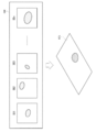
- FIG. 5 is a diagram illustrating the operations of the image output unit 130, the input reception unit 140, and the teacher information addition unit 150.
- IB1 to IBn correspond to IA2 to IAm in FIG.
- IB3 among the medical images IB1 to IBn, which are the associated image group GIMs, is selected as the image RIM to be given.
- n is an integer of 2 or more.
- the image output unit 130 causes the display unit 300 to display the image RIM to be given selected by the image association unit 120.
- the user assigns the representative teacher information ATIN to the image RIM to be granted via the operation unit 400.
- the representative teacher information ATIN is the teacher information given to the image RIM to be given.
- FIG. 5 illustrates an example in which the teacher information is contour information surrounding a detection target in machine learning, but the teacher information may be a text, a rectangle, a contour, or an area.
- the text is information used as teacher data of AI that performs classification processing.
- the text is information indicating the content or state of the object to be imaged, and indicates, for example, the type of lesion, the malignancy of the lesion, or the like.
- the rectangle is information used as teacher data of AI that performs detection.
- the rectangle is a rectangle circumscribing the imaged object such as a lesion, and indicates the existence and position of the lesion or the like.
- the contour or region is information used as teacher data of AI for performing segmentation.
- the contour is information indicating the boundary between an imaged object such as a lesion and a region other than the imaged object such as a property mucosa.
- the area is information indicating an area occupied by an imaged object such as a lesion, and includes contour information.
- the teacher information giving unit 150 assigns teacher information AT1 to ATn to the medical images IB1 to IBn included in the associated image group GIM based on the representative teacher information ATIN received by the input receiving unit 140.
- the representative teacher information ATIN is assigned as the teacher information AT3 to the IB3 which is the image RIM to be assigned.
- the teacher information giving unit 150 gives teacher information to medical images other than IB3 by geometrically transforming the representative teacher information ATIN based on the feature points. That is, between two images having two or more feature points in common, the amount of translation, the amount of rotation, and the scaling factor between the images can be known from the positions and correspondences of the feature points.
- the teacher information giving unit 150 converts the representative teacher information ATIN into teacher information AT1, AT2, AT4 to ATn by geometric transformation using the translation amount, the rotation amount, and the scaling factor.
- the image output unit 130 outputs the medical image selected from the associated image group GIM to the display unit 300 as the image to be given RIM.
- any of the medical images included in the associated image group GIM is displayed on the display unit 300 as the image to be given RIM. Since this grant target image RIM is associated with other medical images in the associated image group GIM, the teacher information of each medical image can be assigned from the representative teacher information ATIN by using the correspondence.
- the number of medical images associated with each medical image in the association based on the similarity of the imaging target is defined as the number of associated images.
- the number of associated images of IX1 to IX5 is 2, 3, 3, 2, 2, respectively.
- the image output unit 130 outputs a medical image selected based on the number of associated images to the display unit 300 as a target image RIM.
- the image associating unit 120 selects a grant target image RIM from a plurality of medical images based on the number of associated images, and medical treatment associated with the grant target image RIM among the plurality of medical images. Let the image be the associated image group GIM. More specifically, the image association unit 120 selects the medical image having the largest number of associated images as the image RIM to be given, among the plurality of medical images for which the number of associated images has been calculated.
- the image associating unit 120 selects the image RIM to be given, but the image output unit 130 may select the image RIM to be given.
- the image output unit 130 selects one of the plurality of candidates as the image to be given. May be good.
- the image output unit 130 may select, for example, an image having a large number of feature points included in the candidate image as the image to be given.
- the input reception unit 140 receives the representative contour information indicating the contour of the specific area of the image RIM to be given as the representative teacher information ATIN.
- the teacher information giving unit 150 gives contour information as teacher information AT1 to ATn to the medical images included in the associated image group GIM.
- the specific area is an area to be detected by AI that is machine-learned based on the teacher image generated by the teacher data creation system 10.
- contour information indicating the contour of a specific region is added to the medical image as teacher information AT1 to ATn. Therefore, by performing machine learning based on the teacher information, detection of the specific region by segmentation can be performed. It will be possible.
- the image associating unit 120 extracts feature points FPa to FPc indicating the features of the images from the medical images of the plurality of medical images IA1 to IAm, and is common among the plurality of medical images IA1 to IAm.
- the associated image group GIM is created by associating the medical images IB1 to IBn having the feature points of.
- the teacher information giving unit 150 uses the common feature points FPa to FPc to provide contour information indicating the contour of a specific area with respect to the medical images IB1 to IBn included in the associated image group GIM. Granted as.
- contour information can be added to each medical image by using the information of the feature points matched when creating the associated image group GIM.
- representative contour information can be converted into contour information of each medical image by geometric transformation between images having common feature points.
- the similarity of the imaged object is determined based on the image similarity.
- the hardware configuration of the teacher data creation system 10 is the same as that in FIG. FIG. 6 is a flowchart of processing in the first modification. Since steps S11 and S15 are the same as steps S1 and S5 in FIG. 2, description thereof will be omitted.
- the image association unit 120 calculates the image similarity between medical images included in a plurality of medical images.
- the image similarity is an index showing how similar the two images are, that is, an index showing the similarity of the images themselves. When the images are similar, it can be judged that the similarity of the objects to be photographed in the image is also high.
- the image similarity is, for example, SSD (Sum of Squared Difference), SAD (Sum of Absolute Difference), NCC (Normalized Cross Correlation), ZNCC (Zero-mean Normalized Cross Correlation), or the like.
- the image association unit 120 selects an image having a high degree of image similarity among a plurality of medical images as an image to be given. For example, the image association unit 120 determines the level of similarity by comparing the image similarity with the threshold value. The selection of the image to be given and the setting of the associated image group are the same as those described in FIG. 4 and the like.
- the image output unit 130 outputs the selected image to be given to the display unit 300.
- step S14 the input receiving unit 140 receives the teacher information input for the displayed image to be given.
- the teacher information when the image similarity is used, for example, text is assumed, but the teacher information is not limited to this.
- FIG. 7 is an example of an image displayed on the display unit 300 in the second modification.
- the image output unit 130 outputs to the display unit 300 the association information 303 between the image RIM to be given and the medical image 302 of the plurality of medical images excluding the image RIM to be given.
- 301 is an arrow indicating the flow of time. That is, the medical images 302 are displayed in chronological order along the arrow 301.
- the association information 303 is a line connecting the image RIM to be given and the medical image 302. Images connected by lines are images that are judged to have high similarity to the shooting targets and are associated with each other, and images that are not connected by lines are judged to have low similarity to the shooting targets and are not associated with each other. It is an image.
- the user can know the associative status between the image RIM to be given and each medical image. For example, the user can determine whether or not an appropriate medical image is selected as the image to be given RIM.
- the input receiving unit 140 accepts an input for designating any of the medical images 302 excluding the image to be given RIM as a new image to be given.
- the input receiving unit 140 changes the image to be given based on the received input. That is, the user looks at the association information 303 displayed on the display unit 300, and when it is determined that there is a grant target image that is more suitable than the current grant target image RIM, the user selects the medical image.
- the input reception unit 140 uses the medical image selected by the user as a new image to be given.
- a medical image that the user deems appropriate as a medical image to which the representative teacher information is given can be newly selected as the image to be given, and the user can give the representative teacher information to the image to be given. This makes it possible to create a teacher image that can realize more accurate machine learning.
- the image association unit 120 may reset the association image group, and the image output unit 130 may display the association information on the display unit 300. That is, the image association unit 120 sets a medical image having a high similarity to the image to be given newly selected by the user in the new association image group, and outputs the association information to the image output unit 130. May be good.
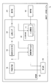
- FIG. 8 is a configuration example of the teacher data creation system 10 in the third modification.
- the processing unit 100 further includes a detection unit 160.
- the image output unit 130 includes a display adjustment unit 131. The components already described will be omitted as appropriate.
- FIG. 9 is a flowchart of processing in the third modification. Since steps S21, S26, and S27 are the same as steps S1, S4, and S5 in FIG. 2, description thereof will be omitted.
- the detection unit 160 detects a specific region from each medical image of a plurality of medical images.
- the specific area is an area to which teacher information is given.
- the image association unit 120 extracts feature points from each medical image of a plurality of medical images and matches the feature points between the images. At this time, the image association unit 120 may extract feature points based on the specific region detected by the detection unit 160. For example, the image matching unit 120 may extract feature points that characterize a specific area.
- step S24 the display adjustment unit 131 enlarges / reduces the image to be given and displays it on the display unit 300 according to the status of the associated image. For example, in the associated image group, when the size of the specific area reflected in the image is large or small, the display adjustment unit 131 scales the image to be given so that the size of the specific area becomes appropriate.
- step S25 the display adjustment unit 131 adjusts the detected specific area so that it is easy to see, and causes the display unit 300 to display the image to be given. For example, the display adjustment unit 131 translates the specific area so that it is in the center of the screen, or performs rotation processing or projective conversion so that the specific area is easy to see.
- the projective transformation is a transformation that changes the inclination of a surface on which a specific region exists, that is, a transformation that changes the angle formed by the surface on which the specific region exists and the line of sight of the camera. Both steps S25 and S24 may be carried out, or either one may be carried out.
- the display adjustment unit 131 outputs the image to the display unit 300 after applying geometric transformation to the image to be given.
- Geometric transformations are, for example, translation, rotation, scaling, projective transformations or combinations thereof.
- the geometric transformation can be performed so that the specific area to which the representative teacher information is given by the user can be easily seen.
- the specific area can be presented to the user in an easy-to-see manner, the workload of the user can be reduced, or the user can accurately assign the representative teacher information.
- the detection unit 160 detects information in a specific region from a plurality of medical images by image processing.
- the display adjustment unit 131 adjusts the display of the specific area by performing geometric transformation based on the detected information of the specific area.
- the image processing is an image recognition process that recognizes the position or area of a specific area from an image.
- Various techniques can be adopted as the image recognition process, and one example is an image recognition technique using machine learning or an image recognition technique using feature extraction.
- the information of the specific area to be detected is the position, size, contour, area, or a combination thereof of the specific area. By using this information, it is possible to perform translation, rotation, scaling, etc. so that a specific area is appropriately displayed.
- the specific area to which the teacher information should be assigned is detected in advance by the detection unit 160, and the display adjustment unit 131 can geometrically transform the image to be assigned so that the specific area is appropriately displayed.
- FIG. 10 is a configuration example of the teacher data creation system 10 in the fourth modification.
- the input receiving unit 140 includes the input adjusting unit 141. The components already described will be omitted as appropriate.
- FIG. 11 is a diagram illustrating a first operation example of the input adjusting unit 141.
- the input adjustment unit 141 detects the estimated contour information ATES of a specific region from the image to be given by image processing.
- the input receiving unit 140 receives the representative contour information ATINb indicating the contour of the specific area of the image to be given as the representative teacher information.
- the input adjustment unit 141 corrects the representative contour information ATINB based on the estimated contour information ATES when the estimated contour information ATES has a certainty or more certainty.
- the input adjustment unit 141 outputs the estimated contour information ATES and the certainty of the estimation by performing the image recognition processing by the AI processing. For example, the certainty is output for each position along the contour.
- the input adjustment unit 141 corrects the representative contour information ATINB based on the estimated contour information ATES for the portion whose certainty is equal to or higher than a predetermined value. For example, the input adjustment unit 141 replaces the representative contour information ATINB with the estimated contour information ATES for the portion whose certainty is equal to or higher than a predetermined value.
- the input adjustment unit 141 outputs the corrected representative contour information to the teacher information addition unit 150 as the final representative teacher information ATF.
- the representative contour information input by the user is corrected based on the estimated contour information. For example, it is assumed that the contour information input by the user is inaccurate, and even in such a case, the contour information can be corrected to be accurate. At this time, since the correction is performed only when the estimated contour information is certain, the correction with high accuracy is possible.
- FIG. 12 is a diagram illustrating a second operation example of the input adjusting unit 141.
- the input adjustment unit 141 detects the estimated contour information ATES of a specific region from the image to be given by image processing.
- the input receiving unit 140 receives the representative contour information ATINb indicating the contour of the specific area of the image to be given as the representative teacher information.
- the input adjustment unit 141 outputs representative teacher information based on the estimated contour information ATES, and the estimated contour information ATES has a certainty of less than a predetermined value. If so, the representative teacher information is output based on the representative contour information ATINb.
- the input adjustment unit 141 outputs the estimated contour information ATES and the certainty of the estimation by performing the image recognition processing by the AI processing. For example, the certainty about the entire contour is output.
- the input adjustment unit 141 outputs the estimated contour information ATES as the final representative teacher information ATF to the teacher information addition unit 150 when the certainty is equal to or higher than a predetermined value. Further, when the certainty is less than a predetermined value, the input adjusting unit 141 outputs the representative contour information ATINb to the teacher information giving unit 150 as the final representative teacher information ATF.
- FIG. 12 illustrates the case where the estimated contour information ATES is selected.
- the feature points are re-extracted based on the input representative teacher information.
- the hardware configuration of the teacher data creation system 10 is the same as that in FIG.
- the image mapping unit 120 responds by extracting feature points indicating the features of the image from each medical image of the plurality of medical images and associating the medical images having the common feature points among the plurality of medical images. Create a group of attached images.
- the input receiving unit 140 receives the representative contour information indicating the contour of the specific area of the image to be given as the representative teacher information.
- the image associating unit 120 extracts and associates the feature point again based on the position of the contour of the representative contour information.
- the image association unit 120 calculates the distance between the contour of the representative contour information and the feature point of the image to be given.
- the distance is, for example, the distance between the feature point and the point closest to the feature point in the contour.
- the image association unit 120 re-extracts the feature points of each medical image.
- the image associating unit 120 extracts the feature points existing near the contour of the representative contour information input by the user, and reconstructs the associated image group using the feature points.
- the feature points are re-extracted based on the contour of the representative contour information input by the user, so that the feature points related to the specific area recognized by the user are re-extracted.
- the associated image group appropriately associated with the feature points in the specific region can be obtained.
- the teacher information giving unit 150 can accurately give contour information to each medical image based on the representative contour information.
- step S33 the image mapping unit 120 builds a three-dimensional model by synthesizing a plurality of medical images based on the mapping result in step S32.
- step S34 the image output unit 130 adjusts the posture of the three-dimensional model so that many corresponding points in the associated medical image are captured, and outputs a two-dimensional image of that posture to the display unit 300 as an image to be given. do.
- step S35 the input receiving unit 140 receives the input of the representative teacher information for the image to be given.
- the teacher information is assumed to be, for example, a rectangle, an outline, an area, or the like, but is not limited thereto.
- step S36 the input reception unit 140 automatically adjusts the input representative teacher information according to the nearby contour in the 3D model, or automatically adjusts the input representative teacher information according to the depth of the 3D model.
- step S37 the teacher information giving unit 150 adds teacher information to the medical image or region associated with the three-dimensional model based on the representative teacher information given to the three-dimensional model.
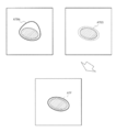
- FIG. 14 is a diagram illustrating the operation of the image mapping unit 120. Although omitted in FIG. 14, feature points are extracted from the medical images IB1 to IBn as in FIG. 3, and medical images having high similarity to the imaging target are associated as the associated image group GIM.
- the image association unit 120 synthesizes a three-dimensional model MDL from the medical images IB1 to IBn by using the association of the medical images IB1 to IBn included in the associated image group GIM. Specifically, the image association unit 120 determines in what camera position and line-of-sight direction each medical image was taken based on the correspondence between the feature points in each medical image and the feature points between the medical images. Estimate and estimate the 3D model MDL based on the estimation result. For example, SfM (Structure from Motion) can be adopted as a method for synthesizing the three-dimensional model MDL.
- SfM Structure from Motion
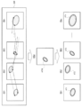
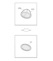
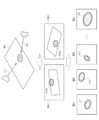
- FIG. 15 is a diagram illustrating the operations of the image output unit 130, the input reception unit 140, and the teacher information addition unit 150.
- the image output unit 130 generates the images to be given RIM1 and RIM2 from the three-dimensional model MDL.
- the images to be given RIM1 and RIM2 are two-dimensional images when the three-dimensional model MDL is viewed with the line of sight VL1 and VL2.
- the line-of-sight VL2 is viewed in the opposite direction to the line-of-sight VL1. That is, if the appearance of the three-dimensional model MDL in the image RIM1 to be given is called the front, the appearance of the three-dimensional model MDL in the image RIM2 to be given is the back.
- FIG. 15 illustrates the case where the teacher information is contour information.
- the input reception unit 140 adds the representative teacher information to the three-dimensional model MDL based on the representative teacher information ATIN1 and ATIN2. That is, the input receiving unit 140 generates the contour of the specific region in the three-dimensional model MDL from the contours of the representative teacher information ATIN1 and ATIN2. For example, when the specific region is a convex portion, the boundary between the convex portion and the surface other than the convex portion is the contour of the specific region in the three-dimensional model MDL.
- the teacher information giving unit 150 gives teacher information AT1 to ATn to the medical images IB1 to IBn of the associated image group GIM based on the representative teacher information given to the three-dimensional model MDL.
- the three-dimensional model MDL is generated, the camera position and the line-of-sight direction corresponding to each medical image are estimated. If a three-dimensional model is generated, the distance between each point on the model and the camera is also estimated.
- the teacher information giving unit 150 converts the representative teacher information in the three-dimensional model MDL into the teacher information AT1 to ATn in the medical images IB1 to IBn by using the camera position and the line-of-sight direction.
- the image output unit 130 outputs an image generated by using the associated image group GIM to the display unit 300 as an image to be given.
- the image generated by using the associated image group GIM is an image related to the shooting target.
- the shooting target is appropriately presented to the user.
- the image output unit 130 generates a three-dimensional model MDL to be photographed based on the associated image group GIM, and displays the images RIM1 and RIM2 based on the three-dimensional model MDL as the images to be assigned to the display unit 300. Output.
- the 3D model MDL to be photographed is presented to the user.
- teacher information is appropriately given to lesions and the like where the 3D structure is important.
- the target image can be displayed.
- the image output unit 130 displays an image to be given when the three-dimensional model MDL is viewed from the camera's line of sight in which more corresponding points are captured.
- Corresponding points are feature points common to the medical images used in the construction of the three-dimensional model MDL. Since the correspondence of feature points is used when constructing the 3D model MDL, the positions of the feature points on the 3D model MDL are known. Therefore, it is possible to know which camera line of sight a large number of corresponding points are captured when the three-dimensional model MDL is viewed, and the image to be given as viewed from that camera line of sight is displayed. Two images to be given, RIM1 and RIM2, are shown in FIG. 15, and for example, the image viewed from the camera line of sight that maximizes the number of corresponding points is set to either RIM1 or RIM2.
- the image output unit 130 outputs a plurality of two-dimensional images RIM1 and RIM2 having different line-of-sight directions with respect to the three-dimensional model MDL to the display unit 300 as a plurality of images to be given.
- the input receiving unit 140 receives representative contour information indicating the contour of a specific area of the image to be given as representative teacher information ATIN1 and ATIN2 for each of the plurality of two-dimensional images.
- the teacher information giving unit 150 gives contour information as teacher information AT1 to ATn to the medical images IB1 to IBn included in the associated image group GIM.
- the 3D model MDL When the 3D model MDL is viewed in one line-of-sight direction, there is a possibility that there is an invisible part behind the convex part or the like.
- the present embodiment by displaying a plurality of two-dimensional images having different line-of-sight directions, two-dimensional images of the three-dimensional model MDL viewed from various directions are displayed, and a representative contour is provided for each of the two-dimensional images. Information is given. As a result, the contour information is given to the three-dimensional model MDL without being lacking.
- two two-dimensional images are displayed as images to be given, but the number of two-dimensional images displayed is not limited to two, and may be a plurality.
- the "image generated by using the associated image group” is an image based on the three-dimensional model MDL has been described as an example, but the present invention is not limited to this, and the corresponding example is described later. It may be a development view of the digestive tract and the like generated from the attached image group GIM.
- the input reception unit 140 receives representative contour information indicating the contour of a specific area of the images to be given RIM1 and RIM2 as representative teacher information ATIN1 and ATIN2.
- the input adjustment unit 141 adjusts the input representative contour information based on the contour and depth of the three-dimensional model MDL.
- the depth is the depth of the 3D model MDL when viewed as a 2D image displayed as the image to be given, and corresponds to the camera line of sight when generating the 2D image.
- the input adjusting unit 141 adjusts the representative contour information so that the contour is attached to the foremost surface.
- the representative contour information is adjusted so as to match the contour of the 3D model MDL close to the representative contour information. adjust.
- the representative contour information in the three-dimensional model MDL can be appropriately given based on the representative contour information given to the image to be given, which is a two-dimensional image. That is, by considering the depth of the three-dimensional model MDL, representative contour information is given to the contour intended by the user. Further, by considering the contour of the three-dimensional model MDL, even if the contour information input by the user is inaccurate, it can be corrected to the accurate contour information.
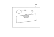
- FIG. 16 is a diagram illustrating a second modification. Although one image to be given is shown in FIG. 16, a plurality of images to be given may be displayed as described above.
- the image output unit 130 generates a two-dimensional image from the three-dimensional model MDL, and outputs the two-dimensional image as a target image RIM.
- the input receiving unit 140 receives the representative contour information ATInc indicating the contour of the specific area of the image RIM to be given as the representative teacher information.
- the input receiving unit 140 indicates error information for instructing a change in the line-of-sight direction when there is no 3D model MDL on the depth of the contour of the representative contour information ATInc in the line-of-sight direction when a two-dimensional image is generated from the three-dimensional model MDL. Is output.
- the three-dimensional model MDL displayed on the image to be given RIM and the representative contour information ATInc do not overlap. That is, there is no 3D model MDL on the depth of the contour of the representative contour information ATInc in the line-of-sight direction.
- the input receiving unit 140 outputs error information.
- the error information is input to the image output unit 130, and the image output unit 130 causes the display unit 300 to display a display prompting the user to change the line-of-sight direction based on the error information.
- the error information is input to the image association unit 120, and the image association unit 120 regenerates the associated image group and the three-dimensional model by re-executing the association of the medical images based on the error information.
- the image output unit 130 redisplays the image to be given.
- FIG. 17 is a flowchart of processing in the third modification. Since steps S41 and S42 are the same as steps S1 and S2 in FIG. 2, description thereof will be omitted.
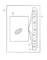
- FIG. 18 is a diagram illustrating a third modified example.
- the image association unit 120 creates a development view TKZ by synthesizing the medical images IB1 to IBn based on the association of the medical images IB1 to IBn in the associated image group GIM. Specifically, the image associating unit 120 attaches the medical images IB1 to IBn so that the positions of the corresponding feature points match based on the correspondence relationship of the feature points between the medical images, so that the developed view TKZ To create.
- FIG. 8 illustrates the bonding of IB1 to IB3 among IB1 to IBn, but IB4 to IBn are also bonded in the same manner.
- the image output unit 130 outputs the image to be given to the display unit 300 based on the development view TKZ.
- the image output unit 130 may display the entire developed view TKZ on the display unit 300, or may display a part of the developed view TKZ in which a specific area is captured on the display unit 300.
- step S44 the input reception unit 140 receives the representative teacher information ATIN input by the user.
- FIG. 18 illustrates a case where the teacher information is contour information.
- the input reception unit 140 automatically adjusts the input representative teacher information according to the nearby contour in the development drawing.
- step S46 the teacher information adding unit 150 adds teacher information to the medical image or area associated with the development drawing based on the representative teacher information given to the development drawing. Since the developed view TKZ is created by pasting the medical images IB1 to IBn in step S43, the position of each medical image in the developed view TKZ is known. The teacher information giving unit 150 converts the representative teacher information ATIN into the teacher information of each medical image by using the position of each medical image in the developed view TKZ.
- the present disclosure is not limited to each embodiment and its modified examples as they are, and at the implementation stage, the components are modified within a range that does not deviate from the gist. Can be embodied.
- a plurality of components disclosed in the above-described embodiments and modifications can be appropriately combined. For example, some components may be deleted from all the components described in each embodiment or modification. Further, the components described in different embodiments and modifications may be combined as appropriate. As described above, various modifications and applications are possible within a range that does not deviate from the gist of the present disclosure.
- a term described at least once in the specification or drawing together with a different term having a broader meaning or a synonym may be replaced with the different term at any part of the specification or drawing.
- Teacher data creation system 100 processing unit, 110 image acquisition unit, 120 image mapping unit, 130 image output unit, 131 display adjustment unit, 140 input reception unit, 141 input adjustment unit, 150 teacher information addition unit, 160 detection unit , 200 storage unit, 300 display unit, 301 arrow, 302 medical image, 303 correspondence information, 400 operation unit, 500 learning device, 510 processor, 520 storage unit, 521 teacher data, 522 learning model, 600 endoscope, AT1 ⁇ ATn teacher information, ATES estimated contour information, ATIN representative teacher information, ATINb representative contour information, FPa ⁇ FPc feature points, GIM associated image group, IA1 ⁇ IAm medical image, IB1 ⁇ IBn medical image, MDL 3D model, RIM Image to be granted, TKZ development view
Abstract
This teaching data creation system (10) comprises an image acquisition unit (110), an image association unit (120), an image output unit (130), an input reception unit (140), and a teaching information imparting unit (150). The image acquisition unit acquires a plurality of medical images. The image association unit associates, with each other, medical images included in the plurality of medical images on the basis of the similarity between objects to be imaged, and creates an association image group configured by grouping medical images that have been able to be associated. The image input unit outputs, on a display unit (300), an image to be imparted to which representative teaching information is to be imparted on the basis of the association image group. The input receiving unit receives an input of the representative teaching information. The teaching information imparting unit imparts teaching information to the medical images included in the association image group on the basis of the representative teaching information to be input to the images to be imparted.
Description
本発明は、教師データ作成システム、教師データ作成方法及び教師データ作成プログラム等に関する。
The present invention relates to a teacher data creation system, a teacher data creation method, a teacher data creation program, and the like.
画像認識技術として、ディープラーニング等の機械学習が広く利用されている。機械学習では、学習に適した教師画像を大量に入力する必要があるが、その大量の教師画像を用意する手法の1つにデータオーギュメンテーションがある。データオーギュメンテーションは、実際に撮影されたオリジナル画像を加工して新たな画像を生成することで、教師画像の枚数を増やす手法である。しかし、機械学習の認識精度を高める点からは、オリジナル画像を大量に用意し、そのオリジナル画像に教師ラベルを付与することが望ましい。特許文献1には、超音波診断装置の機械学習用の画像を生成する医療用画像生成装置が開示されている。特許文献1では、医療用画像生成装置は、ユーザが画像保存操作やフリーズ操作を行ったときに表示されていた医用画像を注目画像として設定し、時系列画像から当該注目画像と類似した複数画像を機械的に抽出する。ユーザは、注目画像にラベル情報を付与する。医療用画像生成装置は、注目画像に付されたラベル情報に基づいて、注目画像と類似した複数画像に対してラベル情報を付与する。
Machine learning such as deep learning is widely used as an image recognition technology. In machine learning, it is necessary to input a large number of teacher images suitable for learning, and one of the methods for preparing the large number of teacher images is data augmentation. Data augmentation is a method of increasing the number of teacher images by processing the actually captured original image to generate a new image. However, from the viewpoint of improving the recognition accuracy of machine learning, it is desirable to prepare a large number of original images and attach a teacher label to the original images. Patent Document 1 discloses a medical image generator that generates an image for machine learning of an ultrasonic diagnostic apparatus. In Patent Document 1, the medical image generator sets a medical image displayed when the user performs an image saving operation or a freeze operation as a attention image, and a plurality of images similar to the attention image from a time-series image. Is mechanically extracted. The user gives label information to the image of interest. The medical image generation device adds label information to a plurality of images similar to the attention image based on the label information attached to the attention image.
上記特許文献1では、ユーザが画像保存操作やフリーズ操作を行ったときの画像が注目画像となるため、時系列画像に対して類似性が低い、又は時系列画像の中で類似性が高い画像数が少ない画像が、注目画像となる可能性がある。この場合、注目画像に付与されたラベル情報を用いて、医療用画像生成装置が時系列画像にラベル情報を付与できない、又は医療用画像生成装置がラベル情報を付与できる画像数が少ないという課題がある。例えば、内視鏡等においてカメラのアングルを一時的に大きく変えたときに撮影された画像が注目画像となった場合、そのアングル以外で撮影された画像に対しては類似性に基づくラベル情報の付与ができない可能性がある。
In Patent Document 1, since the image when the user performs the image saving operation or the freeze operation is the image of interest, the image has low similarity to the time-series image or has high similarity among the time-series images. An image with a small number may be a noteworthy image. In this case, there is a problem that the medical image generator cannot add the label information to the time-series image using the label information given to the image of interest, or the number of images to which the medical image generator can give the label information is small. be. For example, when an image taken when the camera angle is temporarily changed significantly in an endoscope or the like becomes a noteworthy image, label information based on similarity is used for images taken at other angles. It may not be possible to grant.
本開示の一態様は、複数の医療画像を取得する画像取得部と、前記複数の医療画像に含まれる医療画像間で撮影対象の類似性に基づく対応付けを行い、対応付けできた医療画像同士で群を構成した対応付け画像群を作成する画像対応付け部と、前記対応付け画像群に基づいて、代表教師情報の付与対象となる画像である付与対象画像を表示部に出力する画像出力部と、前記代表教師情報の入力を受け付ける入力受付部と、前記付与対象画像に対して入力された前記代表教師情報に基づいて、前記対応付け画像群に含まれる医療画像に対して教師情報を付与する教師情報付与部と、を含む教師データ作成システムに関係する。
In one aspect of the present disclosure, an image acquisition unit that acquires a plurality of medical images and medical images included in the plurality of medical images are associated with each other based on the similarity of imaging targets, and the medical images that can be associated with each other are associated with each other. An image mapping unit that creates a group of associated images composed of And, based on the input receiving unit that accepts the input of the representative teacher information and the representative teacher information input to the image to be given, the teacher information is given to the medical image included in the associated image group. It is related to the teacher information addition department and the teacher data creation system including.
本開示の他の態様は、複数の医療画像を取得することと、前記複数の医療画像に含まれる医療画像間で撮影対象の類似性に基づく対応付けを行い、対応付けできた医療画像同士で群を構成した対応付け画像群を作成することと、前記対応付け画像群に基づいて、代表教師情報の付与対象となる画像である付与対象画像を表示部に出力することと、前記代表教師情報の入力を受け付けることと、前記付与対象画像に対して入力された前記代表教師情報に基づいて、前記対応付け画像群に含まれる医療画像に対して教師情報を付与することと、を含む教師データ作成方法に関係する。
In another aspect of the present disclosure, a plurality of medical images are acquired, and the medical images included in the plurality of medical images are associated with each other based on the similarity of the imaging target, and the medical images that can be associated with each other are associated with each other. Creating a group of associated images that constitute a group, outputting the image to be assigned, which is an image to be assigned the representative teacher information, to the display unit based on the associated image group, and the representative teacher information. Teacher data including accepting the input of and adding teacher information to the medical image included in the associated image group based on the representative teacher information input to the image to be given. It is related to the creation method.
本開示の更に他の態様は、複数の医療画像を取得することと、前記複数の医療画像に含まれる医療画像間で撮影対象の類似性に基づく対応付けを行い、対応付けできた医療画像同士で群を構成した対応付け画像群を作成することと、前記対応付け画像群に基づいて、代表教師情報の付与対象となる画像である付与対象画像を表示部に出力することと、前記代表教師情報の入力を受け付けることと、前記付与対象画像に対して入力された前記代表教師情報に基づいて、前記対応付け画像群に含まれる医療画像に対して教師情報を付与することと、をコンピュータに実行させる教師データ作成プログラムに関係する。
In still another aspect of the present disclosure, a plurality of medical images are acquired, and the medical images included in the plurality of medical images are associated with each other based on the similarity of the imaging target, and the medical images that can be associated with each other are associated with each other. Creating a group of associated images composed of The computer is instructed to accept the input of information and to give teacher information to the medical image included in the associated image group based on the representative teacher information input to the image to be given. It is related to the teacher data creation program to be executed.
以下、本実施形態について説明する。なお、以下に説明する本実施形態は、請求の範囲に記載された内容を不当に限定するものではない。また本実施形態で説明される構成の全てが、本開示の必須構成要件であるとは限らない。
Hereinafter, this embodiment will be described. The present embodiment described below does not unreasonably limit the contents described in the claims. Moreover, not all of the configurations described in the present embodiment are essential constituent requirements of the present disclosure.
1.第1構成例
図1は、教師データ作成システム10の第1構成例である。教師データ作成システム10は、処理部100と記憶部200と表示部300と操作部400とを含む。なお図1には内視鏡600及び学習装置500も図示するが、教師データ作成システム10が教師データを作成する際に、内視鏡600と学習装置500が教師データ作成システム10に接続されている必要はない。 1. 1. First Configuration Example FIG. 1 is a first configuration example of the teacherdata creation system 10. The teacher data creation system 10 includes a processing unit 100, a storage unit 200, a display unit 300, and an operation unit 400. Although the endoscope 600 and the learning device 500 are also shown in FIG. 1, when the teacher data creating system 10 creates teacher data, the endoscope 600 and the learning device 500 are connected to the teacher data creating system 10. You don't have to be.
図1は、教師データ作成システム10の第1構成例である。教師データ作成システム10は、処理部100と記憶部200と表示部300と操作部400とを含む。なお図1には内視鏡600及び学習装置500も図示するが、教師データ作成システム10が教師データを作成する際に、内視鏡600と学習装置500が教師データ作成システム10に接続されている必要はない。 1. 1. First Configuration Example FIG. 1 is a first configuration example of the teacher
処理部100は、画像取得部110と画像対応付け部120と画像出力部130と教師情報付与部150と入力受付部140と教師情報付与部150とを含む。画像取得部110は、複数の医療画像を取得する。画像対応付け部120は、複数の医療画像に含まれる医療画像間で撮影対象の類似性に基づく対応付けを行い、対応付け画像群を作成する。対応付け画像群は、上記対応付けにおいて対応付けできた医療画像同士で構成した群である。画像出力部130は、対応付け画像群に基づいて、代表教師情報の付与対象となる画像である付与対象画像を表示部300に出力する。入力受付部140は、操作部400から代表教師情報の入力を受け付ける。教師情報付与部150は、付与対象画像に対して入力された代表教師情報に基づいて、対応付け画像群に含まれる医療画像に対して教師情報を付与する。
The processing unit 100 includes an image acquisition unit 110, an image association unit 120, an image output unit 130, a teacher information addition unit 150, an input reception unit 140, and a teacher information addition unit 150. The image acquisition unit 110 acquires a plurality of medical images. The image mapping unit 120 creates a group of associated images by associating medical images included in a plurality of medical images based on the similarity of imaging targets. The associated image group is a group composed of medical images that can be associated with each other in the above association. The image output unit 130 outputs to the display unit 300 an image to be given, which is an image to be given the representative teacher information, based on the associated image group. The input reception unit 140 receives input of representative teacher information from the operation unit 400. The teacher information giving unit 150 gives teacher information to the medical image included in the associated image group based on the representative teacher information input to the image to be given.
このようにすれば、ユーザに教師情報を付与してもらうために表示部300に表示される付与対象画像は、撮影対象の類似性に基づく対応付けがされた対応付け画像群に基づいて表示される。即ち、ユーザに提示する前に類似性が判断されているため、付与対象画像は対応付け画像群の各医療画像に対して類似性を有する画像となっている。これにより、類似性が高い画像に多く対応付けられた医療画像に対して代表教師情報が付されるので、教師情報付与部150が1つの代表教師情報から、より多くの医療画像に教師情報を自動的に付与できる。結果として、ユーザが代表教師情報を入力すべき付与対象画像の枚数を削減でき、ユーザは少ない作業工数で教師画像を作成できる。
In this way, the image to be given to be displayed on the display unit 300 in order to have the user give teacher information is displayed based on the associated image group that is associated based on the similarity of the shooting target. NS. That is, since the similarity is determined before the image is presented to the user, the image to be given is an image having similarity to each medical image in the associated image group. As a result, the representative teacher information is attached to the medical images associated with many images having high similarity, so that the teacher information assigning unit 150 transfers the teacher information from one representative teacher information to more medical images. Can be granted automatically. As a result, the number of images to be given that the user should input the representative teacher information can be reduced, and the user can create the teacher image with less work man-hours.
以下、図1の教師データ作成システム10の詳細を説明する。
The details of the teacher data creation system 10 of FIG. 1 will be described below.
教師データ作成システム10は、例えばPC(Personal Computer)等の情報処理装置である。或いは、教師データ作成システム10は、端末装置と情報処理装置とがネットワークで接続されたシステムであってもよい。例えば、端末装置が表示部300と操作部400と記憶部200とを含み、情報処理装置が処理部100を含む。或いは、教師データ作成システム10は、複数の情報処理装置がネットワークで接続されたクラウドシステムであってもよい。
The teacher data creation system 10 is an information processing device such as a PC (Personal Computer). Alternatively, the teacher data creation system 10 may be a system in which the terminal device and the information processing device are connected by a network. For example, the terminal device includes a display unit 300, an operation unit 400, and a storage unit 200, and an information processing device includes a processing unit 100. Alternatively, the teacher data creation system 10 may be a cloud system in which a plurality of information processing devices are connected by a network.
記憶部200は、内視鏡600により撮像された複数の医療画像を記憶する。医療画像は、医療用内視鏡により撮影された体内画像である。医療用内視鏡は、消化管用内視鏡等のビデオスコープ、或いは外科手術用の硬性鏡等である。複数の医療画像は、時系列画像である。例えば、内視鏡600は体内の動画を撮影し、その動画の各フレームの画像が個々の医療画像に相当する。記憶部200は、半導体メモリ又はハードディスクドライブ等の記憶装置である。半導体メモリは、例えば、RAM等の揮発性メモリ、或いはEEPROM等の不揮発性メモリである。
The storage unit 200 stores a plurality of medical images captured by the endoscope 600. A medical image is an in-vivo image taken by a medical endoscope. The medical endoscope is a videoscope such as an endoscope for gastrointestinal tract, a rigid scope for surgery, or the like. The plurality of medical images are time series images. For example, the endoscope 600 captures a moving image inside the body, and the image of each frame of the moving image corresponds to an individual medical image. The storage unit 200 is a storage device such as a semiconductor memory or a hard disk drive. The semiconductor memory is, for example, a volatile memory such as RAM or a non-volatile memory such as EEPROM.
処理部100はプロセッサである。プロセッサは、CPU、マイクロコンピュータ、DSP、ASIC(Application Specific Integrated Circuit)又はFPGA(Field Programmable Gate Array)等の集積回路装置であってもよい。処理部100は、1又は複数のプロセッサを含んでもよい。また、プロセッサである処理部100は、例えば1又は複数の回路部品により構成された処理回路又は処理装置であってもよいし、或いは、1又は複数の回路部品が基板に実装された回路装置であってもよい。
The processing unit 100 is a processor. The processor may be an integrated circuit device such as a CPU, a microcomputer, a DSP, an ASIC (Application Specific Integrated Circuit) or an FPGA (Field Programmable Gate Array). The processing unit 100 may include one or more processors. Further, the processing unit 100 which is a processor may be, for example, a processing circuit or a processing device composed of one or a plurality of circuit components, or a circuit device in which one or a plurality of circuit components are mounted on a substrate. There may be.
処理部100の動作はソフトウェア処理により実現されてもよい。即ち、処理部100に含まれる画像取得部110、画像対応付け部120、画像出力部130、入力受付部140及び教師情報付与部150の全部又は一部の動作を記述したプログラムが、記憶部200に記憶される。その記憶部200に記憶されたプログラムをプロセッサが実行することで、処理部100の動作が実現される。なお、プログラムは、図8で後述する検出部160を更に記述したものであってよい。上記プログラムは、コンピュータにより読み取り可能な媒体である情報記憶媒体に格納されてもよい。情報記憶媒体は、例えば光ディスク、メモリカード、HDD、或いは半導体メモリなどにより実現できる。コンピュータは、入力装置、処理部、記憶部、及び出力部を備える装置である。
The operation of the processing unit 100 may be realized by software processing. That is, the storage unit 200 is a program that describes all or part of the operations of the image acquisition unit 110, the image association unit 120, the image output unit 130, the input reception unit 140, and the teacher information addition unit 150 included in the processing unit 100. Is remembered in. When the processor executes the program stored in the storage unit 200, the operation of the processing unit 100 is realized. The program may further describe the detection unit 160, which will be described later in FIG. The program may be stored in an information storage medium, which is a medium that can be read by a computer. The information storage medium can be realized by, for example, an optical disk, a memory card, an HDD, a semiconductor memory, or the like. A computer is a device including an input device, a processing unit, a storage unit, and an output unit.
図2は、第1構成例における処理のフローチャートである。ステップS1において、画像取得部110は複数の医療画像を取得する。具体的には、画像取得部110は、記憶部200からデータを読み出すアクセス制御部であり、記憶部200から複数の医療画像を取得し、その複数の医療画像を画像対応付け部120に出力する。
FIG. 2 is a flowchart of processing in the first configuration example. In step S1, the image acquisition unit 110 acquires a plurality of medical images. Specifically, the image acquisition unit 110 is an access control unit that reads data from the storage unit 200, acquires a plurality of medical images from the storage unit 200, and outputs the plurality of medical images to the image matching unit 120. ..
ステップS2において、画像対応付け部120は、複数の医療画像の特徴点を抽出し、各特徴点について画像間におけるマッチングを行う。ステップS3において、画像対応付け部120は、マッチングされた特徴点数が多い医療画像を選択し、画像出力部130は、その選択された医療画像を付与対象画像として表示部300に出力する。表示部300は、付与対象画像を表示する。表示部300は、例えば液晶表示装置又はEL(Electro Luminescence)表示装置等のディスプレイである。
In step S2, the image association unit 120 extracts feature points of a plurality of medical images and performs matching between the images for each feature point. In step S3, the image association unit 120 selects a medical image having a large number of matched feature points, and the image output unit 130 outputs the selected medical image to the display unit 300 as an image to be given. The display unit 300 displays the image to be given. The display unit 300 is, for example, a display such as a liquid crystal display device or an EL (Electro Luminescence) display device.
ステップS4において、入力受付部140は、表示された付与対象画像に対する教師情報入力を受け付ける。即ち、ユーザは、表示部300に表示された付与対象画像に対して、操作部400を用いて教師情報を付与し、その付与された教師情報が入力受付部140に入力される。入力受付部140は、例えば操作部400と処理部100の間の通信インターフェースである。操作部400は、ユーザが教師データ作成システム10に対して操作入力又は情報入力を行うための装置であり、例えばポインティングデバイス、キーボード、又はタッチパネル等である。
In step S4, the input receiving unit 140 receives the teacher information input for the displayed image to be given. That is, the user adds teacher information to the image to be given displayed on the display unit 300 by using the operation unit 400, and the given teacher information is input to the input reception unit 140. The input receiving unit 140 is, for example, a communication interface between the operation unit 400 and the processing unit 100. The operation unit 400 is a device for a user to input an operation or information to the teacher data creation system 10, and is, for example, a pointing device, a keyboard, a touch panel, or the like.
ステップS5において、教師情報付与部150は、付与対象画像に付与された教師情報に基づいて、画像対応付け部120により対応付けられた各医療画像に対して教師情報を付与し、その教師情報を記憶部200に記憶させる。教師情報が付与された医療画像を教師画像と呼ぶこととする。
In step S5, the teacher information giving unit 150 gives teacher information to each medical image associated with the image matching unit 120 based on the teacher information given to the image to be given, and applies the teacher information. It is stored in the storage unit 200. A medical image to which teacher information is added is called a teacher image.
記憶部200に記憶された教師画像は、学習装置500に入力される。学習装置500は記憶部520とプロセッサ510とを含む。記憶部200から入力された教師画像は教師データ521として記憶部520に記憶される。記憶部520には、機械学習の学習モデル522が記憶されている。プロセッサ510は、教師データ521を用いて学習モデル522に対する機械学習を行う。機械学習された学習モデル522は、学習済みモデルとして内視鏡に転送され、内視鏡における画像認識に用いられる。
The teacher image stored in the storage unit 200 is input to the learning device 500. The learning device 500 includes a storage unit 520 and a processor 510. The teacher image input from the storage unit 200 is stored in the storage unit 520 as teacher data 521. A learning model 522 for machine learning is stored in the storage unit 520. Processor 510 uses the teacher data 521 to perform machine learning on the learning model 522. The machine-learned learning model 522 is transferred to the endoscope as a trained model and used for image recognition in the endoscope.
図3は、画像対応付け部120の動作を説明する図である。図3において、IA1~IAmは、画像取得部110によって取得された複数の医療画像である。mは3以上の整数である。ここではm=5、即ちIAm=IA5とする。
FIG. 3 is a diagram illustrating the operation of the image associating unit 120. In FIG. 3, IA1 to IAm are a plurality of medical images acquired by the image acquisition unit 110. m is an integer of 3 or more. Here, m = 5, that is, IAm = IA5.
図3では、IA1に特徴点が検出されず、IA2~IA5から共通の特徴点FPaが検出され、IA2~IA4から共通の特徴点FPbが検出され、IA4、IA5から共通の特徴点FPcが検出されている。特徴点とは、画像の特徴を示す点であり、画像から検出された特徴量によって特徴付けられた点である。特徴量として種々想定できるが、例えば画像のエッジ、勾配、又はそれらの統計量等である。画像対応付け部120は、例えばSIFT(Scale Invariant Feature Transform)、SURF(Speeded-Up Robust Features)、HOG(Histograms of Oriented Gradients)等の手法を用いて特徴点を抽出する。
In FIG. 3, feature points are not detected in IA1, common feature point FPa is detected in IA2 to IA5, common feature point FPb is detected in IA2 to IA4, and common feature point FPc is detected in IA4 and IA5. Has been done. A feature point is a point indicating a feature of an image, and is a point characterized by a feature amount detected from the image. Various features can be assumed, such as image edges, gradients, or their statistics. The image mapping unit 120 extracts feature points by using a method such as SIFT (Scale Invariant Feature Transform), SURF (Speeded-Up Robust Features), and HOG (Histograms of Oriented Gradients).
画像対応付け部120は、特徴点FPa~FPcに基づいて、撮影対象の類似性が高い画像群を対応付け画像群GIMとする。「撮影対象の類似性」とは、医療画像に写る対象が類似している度合いであり、類似性が高いほど対象が同一である可能性が高い。特徴点を用いた場合には、共通する特徴点の数が多いほど撮影対象の類似性が高いと判断できる。画像対応付け部120は、例えば共通する特徴点の数がしきい値以上である医療画像を対応付けする。図3の例では、画像対応付け部120は、2以上の特徴点が共通する医療画像を対応付けしており、IA4がIA2、IA3及びIAmの各々に対して2以上の特徴点が共通することから、IA2~IA4、IAmを対応付け画像群GIMとしている。
Based on the feature points FPa to FPc, the image association unit 120 sets an image group having high similarity of the imaging target as the associated image group GIM. The “similarity of the imaged object” is the degree to which the objects shown in the medical image are similar, and the higher the similarity, the higher the possibility that the objects are the same. When the feature points are used, it can be judged that the larger the number of common feature points, the higher the similarity of the imaged objects. The image association unit 120 associates, for example, a medical image in which the number of common feature points is equal to or greater than a threshold value. In the example of FIG. 3, the image associating unit 120 associates a medical image having two or more feature points in common, and IA4 has two or more feature points in common for each of IA2, IA3, and IAm. Therefore, IA2 to IA4 and IAm are designated as the associated image group GIM.
図4は、対応付け画像群の決定手法を説明する図である。ここでは、複数の医療画像としてIX1~IX5が取得されたとする。画像対応付け部120は、IX1~IX5の各医療画像について、他の医療画像との類似性を判断する。〇は類似性が高いと判断されたことを示し、×は類似性が低いと判断されたことを示す。IX1、IX2、IX3、IX4、IX5は、それぞれ2つ、3つ、3つ、2つ、2つの医療画像に対して類似性が高いと判断されている。
FIG. 4 is a diagram illustrating a method for determining the associated image group. Here, it is assumed that IX1 to IX5 are acquired as a plurality of medical images. The image association unit 120 determines the similarity of each medical image of IX1 to IX5 with other medical images. ◯ indicates that the similarity was judged to be high, and × indicates that the similarity was judged to be low. IX1, IX2, IX3, IX4, and IX5 are judged to have high similarity to two, three, three, two, and two medical images, respectively.
画像対応付け部120は、類似性が高い医療画像を多くもつ医療画像を付与対象画像として選択し、その付与対象画像に対して類似性が高い医療画像を対応付け画像群とする。図4の例では、IX2が付与対象画像として選択され、IX1~IX3、IX5が対応付け画像群に設定される。或いは、IX3が付与対象画像として選択され、IX1~IX4が対応付け画像群に設定される。画像対応付け部120は、例えばIX2、IX3のうち番号が小さい、即ち時系列において前の画像を、付与対象画像として選択してもよい。或いは、画像対応付け部120は、IX4が他の対応付け画像群に含まれる場合に、IX1~IX3、IX5を対応付け画像群とする等、他の対応付け画像群を考慮して対応付け画像群を選択してもよい。
The image matching unit 120 selects a medical image having many highly similar medical images as the image to be given, and sets the medical image having high similarity to the image to be given as the associated image group. In the example of FIG. 4, IX2 is selected as the image to be given, and IX1 to IX3 and IX5 are set in the associated image group. Alternatively, IX3 is selected as the image to be given, and IX1 to IX4 are set in the associated image group. The image association unit 120 may select, for example, the image having the smaller number among IX2 and IX3, that is, the previous image in the time series as the image to be assigned. Alternatively, when IX4 is included in another associated image group, the image mapping unit 120 considers the other associated image group, such as IX1 to IX3 and IX5 as the associated image group. You may select a group.
図5は、画像出力部130、入力受付部140及び教師情報付与部150の動作を説明する図である。図5において、IB1~IBnは図3のIA2~IAmに相当する。図4で説明した手法により、対応付け画像群GIMである医療画像IB1~IBnのうちIB3が付与対象画像RIMとして選択されている。nは2以上の整数である。
FIG. 5 is a diagram illustrating the operations of the image output unit 130, the input reception unit 140, and the teacher information addition unit 150. In FIG. 5, IB1 to IBn correspond to IA2 to IAm in FIG. By the method described with reference to FIG. 4, IB3 among the medical images IB1 to IBn, which are the associated image group GIMs, is selected as the image RIM to be given. n is an integer of 2 or more.
画像出力部130は、画像対応付け部120により選択された付与対象画像RIMを表示部300に表示させる。ユーザは、操作部400を介して代表教師情報ATINを付与対象画像RIMに付与する。代表教師情報ATINは、付与対象画像RIMに付与される教師情報のことである。図5には、教師情報が、機械学習における検出対象を囲む輪郭情報である例を図示するが、教師情報は、テキスト、矩形、輪郭、又は領域であってもよい。テキストは、分類処理を行うAIの教師データとして用いられる情報である。テキストは、撮影対象の内容又は状態等を示す情報であり、例えば病変の種類、或いは病変の悪性度等を示す。矩形は、ディテクションを行うAIの教師データとして用いられる情報である。矩形は、病変等の撮影対象に外接する矩形であり、病変等の存在及びその位置を示す。輪郭又は領域は、セグメンテーションを行うAIの教師データとして用いられる情報である。輪郭は、病変等の撮影対象と、性状粘膜等の撮影対象以外の領域との境界を示す情報である。領域は、病変等の撮影対象が占める領域を示す情報であり、輪郭の情報を包含する。
The image output unit 130 causes the display unit 300 to display the image RIM to be given selected by the image association unit 120. The user assigns the representative teacher information ATIN to the image RIM to be granted via the operation unit 400. The representative teacher information ATIN is the teacher information given to the image RIM to be given. FIG. 5 illustrates an example in which the teacher information is contour information surrounding a detection target in machine learning, but the teacher information may be a text, a rectangle, a contour, or an area. The text is information used as teacher data of AI that performs classification processing. The text is information indicating the content or state of the object to be imaged, and indicates, for example, the type of lesion, the malignancy of the lesion, or the like. The rectangle is information used as teacher data of AI that performs detection. The rectangle is a rectangle circumscribing the imaged object such as a lesion, and indicates the existence and position of the lesion or the like. The contour or region is information used as teacher data of AI for performing segmentation. The contour is information indicating the boundary between an imaged object such as a lesion and a region other than the imaged object such as a property mucosa. The area is information indicating an area occupied by an imaged object such as a lesion, and includes contour information.
教師情報付与部150は、入力受付部140が受け付けた代表教師情報ATINに基づいて、対応付け画像群GIMに含まれる医療画像IB1~IBnに対して教師情報AT1~ATnを付与する。図5では、付与対象画像RIMであるIB3には、教師情報AT3として代表教師情報ATINがそのまま付与される。教師情報付与部150は、IB3以外の医療画像に対して、特徴点に基づいて代表教師情報ATINを幾何学変換することで教師情報を付与する。即ち、2以上の特徴点が共通する2つの画像間において、その特徴点の位置及び対応関係から、画像間の平行移動量、回転量及び拡縮率が分かる。教師情報付与部150は、この平行移動量、回転量及び拡縮率を用いた幾何学変換によって代表教師情報ATINを教師情報AT1、AT2、AT4~ATnに変換する。
The teacher information giving unit 150 assigns teacher information AT1 to ATn to the medical images IB1 to IBn included in the associated image group GIM based on the representative teacher information ATIN received by the input receiving unit 140. In FIG. 5, the representative teacher information ATIN is assigned as the teacher information AT3 to the IB3 which is the image RIM to be assigned. The teacher information giving unit 150 gives teacher information to medical images other than IB3 by geometrically transforming the representative teacher information ATIN based on the feature points. That is, between two images having two or more feature points in common, the amount of translation, the amount of rotation, and the scaling factor between the images can be known from the positions and correspondences of the feature points. The teacher information giving unit 150 converts the representative teacher information ATIN into teacher information AT1, AT2, AT4 to ATn by geometric transformation using the translation amount, the rotation amount, and the scaling factor.
本実施形態によれば、画像出力部130は、対応付け画像群GIMの中から選択される医療画像を、付与対象画像RIMとして表示部300に出力する。
According to the present embodiment, the image output unit 130 outputs the medical image selected from the associated image group GIM to the display unit 300 as the image to be given RIM.
このようにすれば、対応付け画像群GIMに含まれる医療画像のいずれかが付与対象画像RIMとして表示部300に表示される。この付与対象画像RIMは、対応付け画像群GIM内の他の医療画像と対応付けられているので、その対応関係を用いることで代表教師情報ATINから各医療画像の教師情報を付与できる。
In this way, any of the medical images included in the associated image group GIM is displayed on the display unit 300 as the image to be given RIM. Since this grant target image RIM is associated with other medical images in the associated image group GIM, the teacher information of each medical image can be assigned from the representative teacher information ATIN by using the correspondence.
また本実施形態では、撮影対象の類似性に基づく対応付けにおいて各医療画像に対応づけられる医療画像の数を対応付け画像数としたとする。例えば図4においてIX1~IX5の対応付け画像数は、それぞれ2、3、3、2、2である。画像出力部130は、対応付け画像数に基づいて選択される医療画像を、付与対象画像RIMとして表示部300に出力する。
Further, in the present embodiment, it is assumed that the number of medical images associated with each medical image in the association based on the similarity of the imaging target is defined as the number of associated images. For example, in FIG. 4, the number of associated images of IX1 to IX5 is 2, 3, 3, 2, 2, respectively. The image output unit 130 outputs a medical image selected based on the number of associated images to the display unit 300 as a target image RIM.
具体的には、画像対応付け部120は、対応付け画像数に基づいて複数の医療画像の中から付与対象画像RIMを選択し、複数の医療画像のうち付与対象画像RIMに対応付けられた医療画像を対応付け画像群GIMとする。より具体的には、画像対応付け部120は、対応付け画像数を算出した複数の医療画像のうち、対応付け画像数が最も多い医療画像が付与対象画像RIMとして選択する。
Specifically, the image associating unit 120 selects a grant target image RIM from a plurality of medical images based on the number of associated images, and medical treatment associated with the grant target image RIM among the plurality of medical images. Let the image be the associated image group GIM. More specifically, the image association unit 120 selects the medical image having the largest number of associated images as the image RIM to be given, among the plurality of medical images for which the number of associated images has been calculated.
このようにすれば、1つの付与対象画像RIMに対応付けられる画像数が多くなるので、ユーザが代表教師情報ATINを付すべき付与対象画像RIMの数を減らすことができる。これにより、教師画像作成におけるユーザ負担を軽減できる。なお、上記構成例では画像対応付け部120が付与対象画像RIMを選択したが、画像出力部130が付与対象画像RIMを選択してもよい。例えば図4のIX2、IX3のように、類似性が高い画像数が同数となっている候補が複数あるとき、画像出力部130が、その複数の候補のいずれかを付与対象画像として選択してもよい。画像出力部130は、例えば候補画像に含まれる特徴点の数が多いものを付与対象画像として選択してもよい。
By doing so, the number of images associated with one image to be given RIM is increased, so that the number of image RIMs to be given to which the user should attach the representative teacher information ATIN can be reduced. As a result, the burden on the user in creating the teacher image can be reduced. In the above configuration example, the image associating unit 120 selects the image RIM to be given, but the image output unit 130 may select the image RIM to be given. For example, when there are a plurality of candidates having the same number of images with high similarity as in IX2 and IX3 of FIG. 4, the image output unit 130 selects one of the plurality of candidates as the image to be given. May be good. The image output unit 130 may select, for example, an image having a large number of feature points included in the candidate image as the image to be given.
また本実施形態では、入力受付部140は、付与対象画像RIMの特定領域の輪郭を示す代表輪郭情報を代表教師情報ATINとして受け付ける。教師情報付与部150は、対応付け画像群GIMに含まれる医療画像に対して輪郭情報を教師情報AT1~ATnとして付与する。
Further, in the present embodiment, the input reception unit 140 receives the representative contour information indicating the contour of the specific area of the image RIM to be given as the representative teacher information ATIN. The teacher information giving unit 150 gives contour information as teacher information AT1 to ATn to the medical images included in the associated image group GIM.
特定領域とは、教師データ作成システム10により生成された教師画像に基づいて機械学習されるAIが検出対象とする領域のことである。本実施形態によれば、特定領域の輪郭を示す輪郭情報が教師情報AT1~ATnとして医療画像に付与されるので、その教師情報に基づいて機械学習を行うことで、セグメンテーションによる特定領域の検出が可能となる。
The specific area is an area to be detected by AI that is machine-learned based on the teacher image generated by the teacher data creation system 10. According to the present embodiment, contour information indicating the contour of a specific region is added to the medical image as teacher information AT1 to ATn. Therefore, by performing machine learning based on the teacher information, detection of the specific region by segmentation can be performed. It will be possible.
また本実施形態では、画像対応付け部120は、複数の医療画像IA1~IAmの各医療画像から、画像の特徴を示す特徴点FPa~FPcを抽出し、複数の医療画像IA1~IAmのうち共通の特徴点を持つ医療画像IB1~IBnの対応付けを行うことで対応付け画像群GIMを作成する。教師情報付与部150は、共通の特徴点FPa~FPcを利用して、対応付け画像群GIMに含まれる医療画像IB1~IBnに対して、特定領域の輪郭を示す輪郭情報を教師情報AT1~ATnとして付与する。
Further, in the present embodiment, the image associating unit 120 extracts feature points FPa to FPc indicating the features of the images from the medical images of the plurality of medical images IA1 to IAm, and is common among the plurality of medical images IA1 to IAm. The associated image group GIM is created by associating the medical images IB1 to IBn having the feature points of. The teacher information giving unit 150 uses the common feature points FPa to FPc to provide contour information indicating the contour of a specific area with respect to the medical images IB1 to IBn included in the associated image group GIM. Granted as.
このようにすれば、対応付け画像群GIMを作成する際にマッチングされた特徴点の情報を用いて、各医療画像に輪郭情報を付与できる。上述したように、共通する特徴点を有する画像間において、幾何学変換により代表輪郭情報を各医療画像の輪郭情報に変換できる。
In this way, contour information can be added to each medical image by using the information of the feature points matched when creating the associated image group GIM. As described above, representative contour information can be converted into contour information of each medical image by geometric transformation between images having common feature points.
2.第1構成例の変形例
第1変形例では、撮影対象の類似性が画像類似度に基づいて判断される。教師データ作成システム10のハードウェア構成は図1と同様である。図6は、第1変形例における処理のフローチャートである。ステップS11、S15は図2のステップS1、S5と同様であるため説明を省略する。 2. Modification example of the first configuration example In the first modification, the similarity of the imaged object is determined based on the image similarity. The hardware configuration of the teacherdata creation system 10 is the same as that in FIG. FIG. 6 is a flowchart of processing in the first modification. Since steps S11 and S15 are the same as steps S1 and S5 in FIG. 2, description thereof will be omitted.
第1変形例では、撮影対象の類似性が画像類似度に基づいて判断される。教師データ作成システム10のハードウェア構成は図1と同様である。図6は、第1変形例における処理のフローチャートである。ステップS11、S15は図2のステップS1、S5と同様であるため説明を省略する。 2. Modification example of the first configuration example In the first modification, the similarity of the imaged object is determined based on the image similarity. The hardware configuration of the teacher
ステップS12において、画像対応付け部120は、複数の医療画像に含まれる医療画像間の画像類似度を算出する。画像類似度は、2つの画像がどの程度類似しているかを示す指標、即ち画像そのものの類似性を示す指標である。画像が類似している場合、その画像に写る撮影対象の類似性も高いと判断できる。画像類似度は、例えばSSD(Sum of Squared Difference)、SAD(Sum of Absolute Difference)、NCC(Normalized Cross Correlation)、ZNCC(Zero-mean Normalized Cross Correlation)等である。
In step S12, the image association unit 120 calculates the image similarity between medical images included in a plurality of medical images. The image similarity is an index showing how similar the two images are, that is, an index showing the similarity of the images themselves. When the images are similar, it can be judged that the similarity of the objects to be photographed in the image is also high. The image similarity is, for example, SSD (Sum of Squared Difference), SAD (Sum of Absolute Difference), NCC (Normalized Cross Correlation), ZNCC (Zero-mean Normalized Cross Correlation), or the like.
ステップS13において、画像対応付け部120は、複数の医療画像のうち高い画像類似度を多く持つ画像を付与対象画像として選択する。例えば画像対応付け部120は、画像類似度としきい値を比較することで、類似度の高低を判断する。付与対象画像の選択と、対応付け画像群の設定については、図4等で説明した手法と同様である。画像出力部130は、選択された付与対象画像を表示部300に出力する。
In step S13, the image association unit 120 selects an image having a high degree of image similarity among a plurality of medical images as an image to be given. For example, the image association unit 120 determines the level of similarity by comparing the image similarity with the threshold value. The selection of the image to be given and the setting of the associated image group are the same as those described in FIG. 4 and the like. The image output unit 130 outputs the selected image to be given to the display unit 300.
ステップS14において、入力受付部140は、表示された付与対象画像に対する教師情報入力を受け付ける。画像類似度を用いた場合の教師情報としては、例えばテキストが想定されるが、これに限定されない。
In step S14, the input receiving unit 140 receives the teacher information input for the displayed image to be given. As the teacher information when the image similarity is used, for example, text is assumed, but the teacher information is not limited to this.
第2変形例では、対応付け状況を表示する。図7は、第2変形例において表示部300に表示される画像の例である。
In the second modification, the association status is displayed. FIG. 7 is an example of an image displayed on the display unit 300 in the second modification.
画像出力部130は、付与対象画像RIMと、複数の医療画像のうち付与対象画像RIMを除く医療画像302との間の対応付け情報303を、表示部300に出力する。図3において、301は、時間の流れを示す矢印である。即ち、矢印301に沿って医療画像302が時系列に表示されている。対応付け情報303は、付与対象画像RIMと医療画像302を接続する線である。線で接続された画像は、撮影対象の類似性が高いと判断されて対応付けされた画像であり、線で接続されない画像は、撮影対象の類似性が低いと判断されて対応付けられなかった画像である。
The image output unit 130 outputs to the display unit 300 the association information 303 between the image RIM to be given and the medical image 302 of the plurality of medical images excluding the image RIM to be given. In FIG. 3, 301 is an arrow indicating the flow of time. That is, the medical images 302 are displayed in chronological order along the arrow 301. The association information 303 is a line connecting the image RIM to be given and the medical image 302. Images connected by lines are images that are judged to have high similarity to the shooting targets and are associated with each other, and images that are not connected by lines are judged to have low similarity to the shooting targets and are not associated with each other. It is an image.
このようにすれば、ユーザは付与対象画像RIMと各医療画像の対応付け状況を知ることができる。例えば、ユーザは、付与対象画像RIMとして適切な医療画像が選択されているか否かを判断できる。
In this way, the user can know the associative status between the image RIM to be given and each medical image. For example, the user can determine whether or not an appropriate medical image is selected as the image to be given RIM.
入力受付部140は、付与対象画像RIMを除く医療画像302のいずれかを、新たな付与対象画像に指定する入力を、受け付ける。入力受付部140は、受け付けた入力に基づいて付与対象画像を変更する。即ち、ユーザは、表示部300に表示された対応付け情報303を見て、現在の付与対象画像RIMよりも適切な付与対象画像があると判断した場合に、その医療画像を選択する。入力受付部140は、ユーザにより選択された医療画像を新たな付与対象画像とする。
The input receiving unit 140 accepts an input for designating any of the medical images 302 excluding the image to be given RIM as a new image to be given. The input receiving unit 140 changes the image to be given based on the received input. That is, the user looks at the association information 303 displayed on the display unit 300, and when it is determined that there is a grant target image that is more suitable than the current grant target image RIM, the user selects the medical image. The input reception unit 140 uses the medical image selected by the user as a new image to be given.
このようにすれば、ユーザが代表教師情報を付与する医療画像として適切と判断した医療画像を付与対象画像として新たに選択し、その付与対象画像に対してユーザが代表教師情報を付与できる。これにより、より高精度な機械学習を実現できる教師画像を作成可能である。
In this way, a medical image that the user deems appropriate as a medical image to which the representative teacher information is given can be newly selected as the image to be given, and the user can give the representative teacher information to the image to be given. This makes it possible to create a teacher image that can realize more accurate machine learning.
なお、ユーザが新たな付与対象画像を選択した後、画像対応付け部120は対応付け画像群を再設定し、その対応付け情報を画像出力部130が表示部300に表示させてもよい。即ち、画像対応付け部120は、ユーザにより新たに選択された付与対象画像と類似性が高い医療画像を新たな対応付け画像群に設定し、その対応付け情報を画像出力部130に出力してもよい。
After the user selects a new image to be given, the image association unit 120 may reset the association image group, and the image output unit 130 may display the association information on the display unit 300. That is, the image association unit 120 sets a medical image having a high similarity to the image to be given newly selected by the user in the new association image group, and outputs the association information to the image output unit 130. May be good.
第3変形例では、特定領域の表示調整を行う。図8は、第3変形例における教師データ作成システム10の構成例である。図8では、処理部100は検出部160を更に含む。また画像出力部130は表示調整部131を含む。なお、既に説明した構成要素については適宜に説明を省略する。
In the third modification, the display of a specific area is adjusted. FIG. 8 is a configuration example of the teacher data creation system 10 in the third modification. In FIG. 8, the processing unit 100 further includes a detection unit 160. Further, the image output unit 130 includes a display adjustment unit 131. The components already described will be omitted as appropriate.
図9は、第3変形例における処理のフローチャートである。ステップS21、S26、S27は図2のステップS1、S4、S5と同様であるため説明を省略する。
FIG. 9 is a flowchart of processing in the third modification. Since steps S21, S26, and S27 are the same as steps S1, S4, and S5 in FIG. 2, description thereof will be omitted.
ステップS22において、検出部160は複数の医療画像の各医療画像から特定領域を検出する。特定領域は、教師情報を付与する対象となる領域である。ステップS23において、画像対応付け部120は、複数の医療画像の各医療画像から特徴点を抽出し、画像間において特徴点のマッチングを行う。このとき、画像対応付け部120は、検出部160により検出された特定領域に基づいて特徴点を抽出してもよい。例えば、画像対応付け部120は、特定領域を特徴付ける特徴点を抽出してもよい。
In step S22, the detection unit 160 detects a specific region from each medical image of a plurality of medical images. The specific area is an area to which teacher information is given. In step S23, the image association unit 120 extracts feature points from each medical image of a plurality of medical images and matches the feature points between the images. At this time, the image association unit 120 may extract feature points based on the specific region detected by the detection unit 160. For example, the image matching unit 120 may extract feature points that characterize a specific area.
ステップS24において、表示調整部131は、対応付けられた画像の状況に応じて、付与対象画像を拡縮して表示部300に表示させる。例えば対応付け画像群において、画像に写る特定領域のサイズが大きい又は小さい場合に、表示調整部131は、特定領域のサイズが適切となるように付与対象画像を拡縮する。ステップS25において、表示調整部131は、検出された特定領域が見えやすいように調整して、付与対象画像を表示部300に表示させる。例えば、表示調整部131は、特定領域が画面中央となるように平行移動したり、特定領域が見やすいように回転処理又は射影変換したりする。射影変換は、特定領域が存在する面の傾きを変える変換、即ち特定領域が存在する面とカメラ視線のなす角度を変える変換である。なお、ステップS25又はS24の両方が実施されてもよいし、いずれか一方が実施されてもよい。
In step S24, the display adjustment unit 131 enlarges / reduces the image to be given and displays it on the display unit 300 according to the status of the associated image. For example, in the associated image group, when the size of the specific area reflected in the image is large or small, the display adjustment unit 131 scales the image to be given so that the size of the specific area becomes appropriate. In step S25, the display adjustment unit 131 adjusts the detected specific area so that it is easy to see, and causes the display unit 300 to display the image to be given. For example, the display adjustment unit 131 translates the specific area so that it is in the center of the screen, or performs rotation processing or projective conversion so that the specific area is easy to see. The projective transformation is a transformation that changes the inclination of a surface on which a specific region exists, that is, a transformation that changes the angle formed by the surface on which the specific region exists and the line of sight of the camera. Both steps S25 and S24 may be carried out, or either one may be carried out.
本実施形態によれば、表示調整部131は、付与対象画像に幾何学変換を加えた後に表示部300に出力する。幾何学変換は、例えば平行移動、回転、拡縮、射影変換又はそれらの組み合わせである。
According to the present embodiment, the display adjustment unit 131 outputs the image to the display unit 300 after applying geometric transformation to the image to be given. Geometric transformations are, for example, translation, rotation, scaling, projective transformations or combinations thereof.
このようにすれば、ユーザにより代表教師情報が付与される特定領域が見やすくなるように、幾何学変換できる。これにより、特定領域を見やすくユーザに提示でき、ユーザの作業負担を低減できる、或いはユーザが正確に代表教師情報を付与できるようになる。
In this way, the geometric transformation can be performed so that the specific area to which the representative teacher information is given by the user can be easily seen. As a result, the specific area can be presented to the user in an easy-to-see manner, the workload of the user can be reduced, or the user can accurately assign the representative teacher information.
また本実施形態によれば、検出部160は、複数の医療画像から画像処理により特定領域の情報を検出する。表示調整部131は、検出された特定領域の情報に基づいて幾何学変換を行うことで特定領域の表示調整を行う。画像処理は、画像から特定領域の位置又は領域等を認識する画像認識処理である。画像認識処理としては種々の技術を採用できるが、一例としては機械学習を用いた画像認識技術、或いは特徴量抽出を用いた画像認識技術である。検出される特定領域の情報は、特定領域の位置、サイズ、輪郭、領域、又はそれらの組み合わせである。これらの情報を用いることで、特定領域が適切に表示されるように平行移動、回転又は拡縮等を行うことが可能である。
Further, according to the present embodiment, the detection unit 160 detects information in a specific region from a plurality of medical images by image processing. The display adjustment unit 131 adjusts the display of the specific area by performing geometric transformation based on the detected information of the specific area. The image processing is an image recognition process that recognizes the position or area of a specific area from an image. Various techniques can be adopted as the image recognition process, and one example is an image recognition technique using machine learning or an image recognition technique using feature extraction. The information of the specific area to be detected is the position, size, contour, area, or a combination thereof of the specific area. By using this information, it is possible to perform translation, rotation, scaling, etc. so that a specific area is appropriately displayed.
このようにすれば、教師情報が付与されるべき特定領域が予め検出部160によって検出され、その特定領域が適切に表示されるように表示調整部131が付与対象画像を幾何学変換できる。
In this way, the specific area to which the teacher information should be assigned is detected in advance by the detection unit 160, and the display adjustment unit 131 can geometrically transform the image to be assigned so that the specific area is appropriately displayed.
第4変形例では、入力された代表教師情報の調整を行う。図10は、第4変形例における教師データ作成システム10の構成例である。図10では、入力受付部140は入力調整部141を含む。なお、既に説明した構成要素については適宜に説明を省略する。
In the fourth modification, the input representative teacher information is adjusted. FIG. 10 is a configuration example of the teacher data creation system 10 in the fourth modification. In FIG. 10, the input receiving unit 140 includes the input adjusting unit 141. The components already described will be omitted as appropriate.
図11は、入力調整部141の第1動作例を説明する図である。入力調整部141は、付与対象画像から画像処理により特定領域の推定輪郭情報ATESを検出する。入力受付部140は、付与対象画像の特定領域の輪郭を示す代表輪郭情報ATINbを代表教師情報として受け付ける。入力調整部141は、推定輪郭情報ATESが所定以上の確からしさを持っている場合に、代表輪郭情報ATINbを推定輪郭情報ATESに基づいて補正する。
FIG. 11 is a diagram illustrating a first operation example of the input adjusting unit 141. The input adjustment unit 141 detects the estimated contour information ATES of a specific region from the image to be given by image processing. The input receiving unit 140 receives the representative contour information ATINb indicating the contour of the specific area of the image to be given as the representative teacher information. The input adjustment unit 141 corrects the representative contour information ATINB based on the estimated contour information ATES when the estimated contour information ATES has a certainty or more certainty.
入力調整部141は、AI処理による画像認識処理を行うことで、推定輪郭情報ATESと、その推定の確からしさとを出力する。例えば、輪郭に沿った各位置に対して確からしさが出力される。入力調整部141は、確からしさが所定以上の部分について、代表輪郭情報ATINbを推定輪郭情報ATESに基づいて補正する。例えば、入力調整部141は、確からしさが所定以上の部分について、代表輪郭情報ATINbを推定輪郭情報ATESで置き換える。入力調整部141は、補正後の代表輪郭情報を最終的な代表教師情報ATFとして教師情報付与部150に出力する。
The input adjustment unit 141 outputs the estimated contour information ATES and the certainty of the estimation by performing the image recognition processing by the AI processing. For example, the certainty is output for each position along the contour. The input adjustment unit 141 corrects the representative contour information ATINB based on the estimated contour information ATES for the portion whose certainty is equal to or higher than a predetermined value. For example, the input adjustment unit 141 replaces the representative contour information ATINB with the estimated contour information ATES for the portion whose certainty is equal to or higher than a predetermined value. The input adjustment unit 141 outputs the corrected representative contour information to the teacher information addition unit 150 as the final representative teacher information ATF.
本実施形態によれば、画像処理による推定輪郭情報が確からしい場合に、その推定輪郭情報に基づいて、ユーザが入力した代表輪郭情報が補正される。例えば、ユーザが入力した輪郭情報が不正確な場合等が想定されるが、そのような場合であっても、正確な輪郭情報に補正できる。このとき、推定輪郭情報が確からしい場合にのみ補正されるので、確度の高い補正が可能である。
According to this embodiment, when the estimated contour information by image processing is certain, the representative contour information input by the user is corrected based on the estimated contour information. For example, it is assumed that the contour information input by the user is inaccurate, and even in such a case, the contour information can be corrected to be accurate. At this time, since the correction is performed only when the estimated contour information is certain, the correction with high accuracy is possible.
図12は、入力調整部141の第2動作例を説明する図である。入力調整部141は、付与対象画像から画像処理により特定領域の推定輪郭情報ATESを検出する。入力受付部140は、付与対象画像の特定領域の輪郭を示す代表輪郭情報ATINbを代表教師情報として受け付ける。入力調整部141は、推定輪郭情報ATESが所定以上の確からしさを持っている場合に、推定輪郭情報ATESに基づいて代表教師情報を出力し、推定輪郭情報ATESが所定未満の確からしさを持っている場合に、代表輪郭情報ATINbに基づいて代表教師情報を出力する。
FIG. 12 is a diagram illustrating a second operation example of the input adjusting unit 141. The input adjustment unit 141 detects the estimated contour information ATES of a specific region from the image to be given by image processing. The input receiving unit 140 receives the representative contour information ATINb indicating the contour of the specific area of the image to be given as the representative teacher information. When the estimated contour information ATES has a certainty of more than a predetermined value, the input adjustment unit 141 outputs representative teacher information based on the estimated contour information ATES, and the estimated contour information ATES has a certainty of less than a predetermined value. If so, the representative teacher information is output based on the representative contour information ATINb.
入力調整部141は、AI処理による画像認識処理を行うことで、推定輪郭情報ATESと、その推定の確からしさとを出力する。例えば、輪郭全体についての確からしさが出力される。入力調整部141は、確からしさが所定以上の場合に、推定輪郭情報ATESを最終的な代表教師情報ATFとして教師情報付与部150に出力する。また、入力調整部141は、確からしさが所定未満の場合に、代表輪郭情報ATINbを最終的な代表教師情報ATFとして教師情報付与部150に出力する。図12には、推定輪郭情報ATESが選択される場合を図示している。
The input adjustment unit 141 outputs the estimated contour information ATES and the certainty of the estimation by performing the image recognition processing by the AI processing. For example, the certainty about the entire contour is output. The input adjustment unit 141 outputs the estimated contour information ATES as the final representative teacher information ATF to the teacher information addition unit 150 when the certainty is equal to or higher than a predetermined value. Further, when the certainty is less than a predetermined value, the input adjusting unit 141 outputs the representative contour information ATINb to the teacher information giving unit 150 as the final representative teacher information ATF. FIG. 12 illustrates the case where the estimated contour information ATES is selected.
第5変形例では、入力された代表教師情報に基づいて特徴点を再抽出する。教師データ作成システム10のハードウェア構成は図1と同様である。
In the fifth modification, the feature points are re-extracted based on the input representative teacher information. The hardware configuration of the teacher data creation system 10 is the same as that in FIG.
画像対応付け部120は、複数の医療画像の各医療画像から、画像の特徴を示す特徴点を抽出し、複数の医療画像のうち共通の特徴点を持つ医療画像の対応付けを行うことで対応付け画像群を作成する。入力受付部140は、付与対象画像の特定領域の輪郭を示す代表輪郭情報を代表教師情報として受け付ける。画像対応付け部120は、代表輪郭情報の輪郭が特徴点から所定以上離れているとき、代表輪郭情報の輪郭の位置に基づいて、再度、特徴点の抽出と対応付けとを行う。
The image mapping unit 120 responds by extracting feature points indicating the features of the image from each medical image of the plurality of medical images and associating the medical images having the common feature points among the plurality of medical images. Create a group of attached images. The input receiving unit 140 receives the representative contour information indicating the contour of the specific area of the image to be given as the representative teacher information. When the contour of the representative contour information is separated from the feature point by a predetermined value or more, the image associating unit 120 extracts and associates the feature point again based on the position of the contour of the representative contour information.
具体的には、画像対応付け部120は、代表輪郭情報の輪郭と付与対象画像の特徴点との距離を算出する。距離は、例えば輪郭のうち特徴点に最も近い点と特徴点との間の距離である。付与対象画像に複数の特徴点がある場合、各特徴点について距離が求められ、そのうちの最短距離又は平均距離等が最終的な距離として求められる。画像対応付け部120は、求めた距離が所定以上である場合、各医療画像の特徴点を再抽出する。このとき、画像対応付け部120は、ユーザにより入力された代表輪郭情報の輪郭付近に存在する特徴点を抽出し、その特徴点を用いて対応付け画像群の再構成を行う。
Specifically, the image association unit 120 calculates the distance between the contour of the representative contour information and the feature point of the image to be given. The distance is, for example, the distance between the feature point and the point closest to the feature point in the contour. When there are a plurality of feature points in the image to be given, the distance is obtained for each feature point, and the shortest distance or the average distance among them is obtained as the final distance. When the obtained distance is equal to or longer than a predetermined distance, the image association unit 120 re-extracts the feature points of each medical image. At this time, the image associating unit 120 extracts the feature points existing near the contour of the representative contour information input by the user, and reconstructs the associated image group using the feature points.
本実施形態によれば、ユーザにより入力された代表輪郭情報の輪郭に基づいて特徴点が再抽出されるので、ユーザが認識した特定領域に関する特徴点が再抽出される。その特徴点を用いて対応付け画像群が再構成されることで、特定領域の特徴点によって適切に対応付けられた対応付け画像群が得られる。これにより、教師情報付与部150が、代表輪郭情報に基づいて各医療画像に対して精度良く輪郭情報を付与できる。
According to the present embodiment, the feature points are re-extracted based on the contour of the representative contour information input by the user, so that the feature points related to the specific area recognized by the user are re-extracted. By reconstructing the associated image group using the feature points, the associated image group appropriately associated with the feature points in the specific region can be obtained. As a result, the teacher information giving unit 150 can accurately give contour information to each medical image based on the representative contour information.
3.第2構成例
教師データ作成システム10の第2構成例を説明する。教師データ作成システム10のハードウェア構成は図1と同様である。図13は、第2構成例における処理のフローチャートである。ステップS31、S32は、図2のステップS1、S2と同様であるため説明を省略する。 3. 3. Second Configuration Example A second configuration example of the teacherdata creation system 10 will be described. The hardware configuration of the teacher data creation system 10 is the same as that in FIG. FIG. 13 is a flowchart of processing in the second configuration example. Since steps S31 and S32 are the same as steps S1 and S2 in FIG. 2, description thereof will be omitted.
教師データ作成システム10の第2構成例を説明する。教師データ作成システム10のハードウェア構成は図1と同様である。図13は、第2構成例における処理のフローチャートである。ステップS31、S32は、図2のステップS1、S2と同様であるため説明を省略する。 3. 3. Second Configuration Example A second configuration example of the teacher
ステップS33において、画像対応付け部120は、ステップS32における対応付け結果に基づいて複数の医療画像を合成することで、3次元モデルを構築する。ステップS34において、画像出力部130は、対応付けられた医療画像における対応点が多く写るように、3次元モデルの姿勢を調整し、その姿勢の2次元画像を付与対象画像として表示部300に出力する。ステップS35において、入力受付部140は、付与対象画像に対する代表教師情報の入力を受け付ける。教師情報としては、例えば矩形、輪郭又は領域等が想定されるが、これらに限定されない。
In step S33, the image mapping unit 120 builds a three-dimensional model by synthesizing a plurality of medical images based on the mapping result in step S32. In step S34, the image output unit 130 adjusts the posture of the three-dimensional model so that many corresponding points in the associated medical image are captured, and outputs a two-dimensional image of that posture to the display unit 300 as an image to be given. do. In step S35, the input receiving unit 140 receives the input of the representative teacher information for the image to be given. The teacher information is assumed to be, for example, a rectangle, an outline, an area, or the like, but is not limited thereto.
ステップS36において、入力受付部140は、入力された代表教師情報を3次元モデルにおける近くの輪郭に合わせて自動的に調整する、又は入力された代表教師情報を3次元モデルの奥行きに応じて自動的に調整する。ステップS37において、教師情報付与部150は、3次元モデルに付与された代表教師情報に基づいて、3次元モデルに対応付けられた医療画像又は領域に教師情報を付与する。
In step S36, the input reception unit 140 automatically adjusts the input representative teacher information according to the nearby contour in the 3D model, or automatically adjusts the input representative teacher information according to the depth of the 3D model. To adjust. In step S37, the teacher information giving unit 150 adds teacher information to the medical image or region associated with the three-dimensional model based on the representative teacher information given to the three-dimensional model.
図14は、画像対応付け部120の動作を説明する図である。図14では省略しているが、図3と同様に医療画像IB1~IBnから特徴点が抽出されており、撮影対象の類似性が高い医療画像が対応付け画像群GIMとして対応付けられている。
FIG. 14 is a diagram illustrating the operation of the image mapping unit 120. Although omitted in FIG. 14, feature points are extracted from the medical images IB1 to IBn as in FIG. 3, and medical images having high similarity to the imaging target are associated as the associated image group GIM.
画像対応付け部120は、対応付け画像群GIMに含まれる医療画像IB1~IBnの対応付けを用いて、医療画像IB1~IBnから3次元モデルMDLを合成する。具体的には、画像対応付け部120は、各医療画像における特徴点と、医療画像間における特徴点の対応とに基づいて、各医療画像がどのようなカメラ位置及び視線方向で撮影されたかを推定し、その推定結果に基づいて3次元モデルMDLを推定する。3次元モデルMDLの合成手法として、例えばSfM(Structure from Motion)を採用できる。
The image association unit 120 synthesizes a three-dimensional model MDL from the medical images IB1 to IBn by using the association of the medical images IB1 to IBn included in the associated image group GIM. Specifically, the image association unit 120 determines in what camera position and line-of-sight direction each medical image was taken based on the correspondence between the feature points in each medical image and the feature points between the medical images. Estimate and estimate the 3D model MDL based on the estimation result. For example, SfM (Structure from Motion) can be adopted as a method for synthesizing the three-dimensional model MDL.
図15は、画像出力部130、入力受付部140及び教師情報付与部150の動作を説明する図である。画像出力部130は、3次元モデルMDLから付与対象画像RIM1、RIM2を生成する。付与対象画像RIM1、RIM2は、3次元モデルMDLを視線VL1、VL2で見たときの2次元画像である。例えば、視線VL2は、視線VL1に対して見る方向が反対になっている。即ち、付与対象画像RIM1における3次元モデルMDLの見え方を表と呼んだとすると、付与対象画像RIM2における3次元モデルMDLの見え方は裏ということになる。
FIG. 15 is a diagram illustrating the operations of the image output unit 130, the input reception unit 140, and the teacher information addition unit 150. The image output unit 130 generates the images to be given RIM1 and RIM2 from the three-dimensional model MDL. The images to be given RIM1 and RIM2 are two-dimensional images when the three-dimensional model MDL is viewed with the line of sight VL1 and VL2. For example, the line-of-sight VL2 is viewed in the opposite direction to the line-of-sight VL1. That is, if the appearance of the three-dimensional model MDL in the image RIM1 to be given is called the front, the appearance of the three-dimensional model MDL in the image RIM2 to be given is the back.
ユーザは、付与対象画像RIM1、RIM2の各々に対して代表教師情報ATIN1、ATIN2を付与する。図15には、教師情報が輪郭情報である場合を図示している。入力受付部140は、代表教師情報ATIN1、ATIN2に基づいて、3次元モデルMDLに代表教師情報を付与する。即ち、入力受付部140は、3次元モデルMDLにおける特定領域の輪郭を、代表教師情報ATIN1、ATIN2の輪郭から生成する。例えば特定領域が凸部である場合、その凸部と、凸部以外の面との境界が、3次元モデルMDLにおける特定領域の輪郭となる。
The user assigns the representative teacher information ATIN1 and ATIN2 to each of the images RIM1 and RIM2 to be granted. FIG. 15 illustrates the case where the teacher information is contour information. The input reception unit 140 adds the representative teacher information to the three-dimensional model MDL based on the representative teacher information ATIN1 and ATIN2. That is, the input receiving unit 140 generates the contour of the specific region in the three-dimensional model MDL from the contours of the representative teacher information ATIN1 and ATIN2. For example, when the specific region is a convex portion, the boundary between the convex portion and the surface other than the convex portion is the contour of the specific region in the three-dimensional model MDL.
教師情報付与部150は、3次元モデルMDLに付与された代表教師情報に基づいて、対応付け画像群GIMの医療画像IB1~IBnに対して教師情報AT1~ATnを付与する。3次元モデルMDLが生成される際に、各医療画像に対応したカメラ位置及び視線方向が推定されている。また、3次元モデルが生成されていれば、モデル上の各点とカメラ間の距離も推定されている。教師情報付与部150は、そのカメラ位置及び視線方向を用いて3次元モデルMDLにおける代表教師情報を、医療画像IB1~IBnにおける教師情報AT1~ATnに変換する。
The teacher information giving unit 150 gives teacher information AT1 to ATn to the medical images IB1 to IBn of the associated image group GIM based on the representative teacher information given to the three-dimensional model MDL. When the three-dimensional model MDL is generated, the camera position and the line-of-sight direction corresponding to each medical image are estimated. If a three-dimensional model is generated, the distance between each point on the model and the camera is also estimated. The teacher information giving unit 150 converts the representative teacher information in the three-dimensional model MDL into the teacher information AT1 to ATn in the medical images IB1 to IBn by using the camera position and the line-of-sight direction.
本実施形態によれば、画像出力部130は、対応付け画像群GIMを用いて生成された画像を、付与対象画像として表示部300に出力する。
According to the present embodiment, the image output unit 130 outputs an image generated by using the associated image group GIM to the display unit 300 as an image to be given.
対応付け画像群GIMは、撮影対象の類似性に基づいて対応付けられているので、その対応付け画像群GIMを用いて生成された画像は、撮影対象に関する画像となっている。このような画像を付与対象画像として表示部300に表示することで、撮影対象が適切にユーザに提示される。
Since the associated image group GIM is associated based on the similarity of the shooting target, the image generated by using the associated image group GIM is an image related to the shooting target. By displaying such an image on the display unit 300 as an image to be given, the shooting target is appropriately presented to the user.
また本実施形態では、画像出力部130は、対応付け画像群GIMに基づいて撮影対象の3次元モデルMDLを生成し、3次元モデルMDLに基づく画像RIM1、RIM2を付与対象画像として表示部300に出力する。
Further, in the present embodiment, the image output unit 130 generates a three-dimensional model MDL to be photographed based on the associated image group GIM, and displays the images RIM1 and RIM2 based on the three-dimensional model MDL as the images to be assigned to the display unit 300. Output.
このようにすれば、撮影対象の3次元モデルMDLがユーザに提示される。3次元モデルMDLを用いることで、3次元構造が重要な病変部等に対して教師情報が適切に付与されることが期待できる。また、各医療画像における撮影対象の写り方に左右されることなく、任意のカメラ視線で見た3次元モデルMDLをユーザに提示することが可能となり、代表教師情報を付与するのに適した付与対象画像を表示できる。
In this way, the 3D model MDL to be photographed is presented to the user. By using the 3D model MDL, it can be expected that teacher information is appropriately given to lesions and the like where the 3D structure is important. In addition, it is possible to present the 3D model MDL viewed from an arbitrary camera line of sight to the user without being influenced by how the imaged object is captured in each medical image, which is suitable for assigning representative teacher information. The target image can be displayed.
具体的には、画像出力部130は、対応点がより多く写るカメラ視線で3次元モデルMDLを見たときの付与対象画像を表示する。対応点は、3次元モデルMDLの構築に用いられた医療画像間において共通する特徴点のことである。3次元モデルMDLを構築する際に特徴点の対応を用いているため、3次元モデルMDL上における特徴点の位置が分かっている。このため、3次元モデルMDLをどのカメラ視線で見たときに多くの対応点が写るのかを知ることができ、そのカメラ視線で見た付与対象画像が表示される。図15には2つの付与対象画像RIM1、RIM2が図示されているが、例えば、対応点の数が最大となるカメラ視線で見た画像を、RIM1、RIM2のいずれか一方にする。
Specifically, the image output unit 130 displays an image to be given when the three-dimensional model MDL is viewed from the camera's line of sight in which more corresponding points are captured. Corresponding points are feature points common to the medical images used in the construction of the three-dimensional model MDL. Since the correspondence of feature points is used when constructing the 3D model MDL, the positions of the feature points on the 3D model MDL are known. Therefore, it is possible to know which camera line of sight a large number of corresponding points are captured when the three-dimensional model MDL is viewed, and the image to be given as viewed from that camera line of sight is displayed. Two images to be given, RIM1 and RIM2, are shown in FIG. 15, and for example, the image viewed from the camera line of sight that maximizes the number of corresponding points is set to either RIM1 or RIM2.
対応点が多く写る画像が表示されるということは、対応付け画像群GIMから3次元モデルMDLを構築する際に対応付けの精度が高い部分が表示されるということである。このような付与対象画像は、対応付け画像群GIMの各医療画像に対して対応付けの精度が高いと考えられる。このため、付与対象画像に付与された代表教師情報に基づいて各医療画像に教師情報を付与する際に、高精度な教師情報を生成できる。
The fact that an image showing many corresponding points is displayed means that a part with high matching accuracy is displayed when constructing a 3D model MDL from the associated image group GIM. It is considered that such an image to be given has high accuracy of association with each medical image of the associated image group GIM. Therefore, highly accurate teacher information can be generated when the teacher information is given to each medical image based on the representative teacher information given to the image to be given.
また本実施形態では、画像出力部130は、3次元モデルMDLに対する視線方向が異なる複数の2次元画像RIM1、RIM2を、複数の付与対象画像として表示部300に出力する。入力受付部140は、複数の2次元画像の各々について、付与対象画像の特定領域の輪郭を示す代表輪郭情報を代表教師情報ATIN1、ATIN2として受け付ける。教師情報付与部150は、対応付け画像群GIMに含まれる医療画像IB1~IBnに対して輪郭情報を教師情報AT1~ATnとして付与する。
Further, in the present embodiment, the image output unit 130 outputs a plurality of two-dimensional images RIM1 and RIM2 having different line-of-sight directions with respect to the three-dimensional model MDL to the display unit 300 as a plurality of images to be given. The input receiving unit 140 receives representative contour information indicating the contour of a specific area of the image to be given as representative teacher information ATIN1 and ATIN2 for each of the plurality of two-dimensional images. The teacher information giving unit 150 gives contour information as teacher information AT1 to ATn to the medical images IB1 to IBn included in the associated image group GIM.
3次元モデルMDLを1つの視線方向に見たとき、凸部等の裏になって見えない部分が存在する可能性がある。本実施形態によれば、視線方向が異なる複数の2次元画像を表示することで、3次元モデルMDLを様々な方向から見た2次元画像が表示され、その各2次元画像に対して代表輪郭情報が付与される。これにより、輪郭情報が欠けることなく3次元モデルMDLに付与される。なお、図15では、2つの2次元画像が付与対象画像として表示されるが、表示される2次元画像は2つに限定されず、複数であればよい。
When the 3D model MDL is viewed in one line-of-sight direction, there is a possibility that there is an invisible part behind the convex part or the like. According to the present embodiment, by displaying a plurality of two-dimensional images having different line-of-sight directions, two-dimensional images of the three-dimensional model MDL viewed from various directions are displayed, and a representative contour is provided for each of the two-dimensional images. Information is given. As a result, the contour information is given to the three-dimensional model MDL without being lacking. In FIG. 15, two two-dimensional images are displayed as images to be given, but the number of two-dimensional images displayed is not limited to two, and may be a plurality.
なお、以上では「対応付け画像群を用いて生成された画像」が3次元モデルMDLに基づく画像である場合を例に説明したが、これに限定されず、後述する変形例のように、対応付け画像群GIMから生成された消化管等の展開図であってもよい。
In the above, the case where the "image generated by using the associated image group" is an image based on the three-dimensional model MDL has been described as an example, but the present invention is not limited to this, and the corresponding example is described later. It may be a development view of the digestive tract and the like generated from the attached image group GIM.
4.第2構成例の変形例
第1変形例では、代表輪郭情報の入力調整を行う。教師データ作成システム10のハードウェア構成は図10と同様である。 4. Modification example of the second configuration example In the first modification, the input adjustment of the representative contour information is performed. The hardware configuration of the teacherdata creation system 10 is the same as that in FIG.
第1変形例では、代表輪郭情報の入力調整を行う。教師データ作成システム10のハードウェア構成は図10と同様である。 4. Modification example of the second configuration example In the first modification, the input adjustment of the representative contour information is performed. The hardware configuration of the teacher
入力受付部140は、付与対象画像RIM1、RIM2の特定領域の輪郭を示す代表輪郭情報を代表教師情報ATIN1、ATIN2として受け付ける。入力調整部141は、入力された代表輪郭情報を、3次元モデルMDLの輪郭と奥行とに基づいて調整する。
The input reception unit 140 receives representative contour information indicating the contour of a specific area of the images to be given RIM1 and RIM2 as representative teacher information ATIN1 and ATIN2. The input adjustment unit 141 adjusts the input representative contour information based on the contour and depth of the three-dimensional model MDL.
奥行きは、付与対象画像として表示される2次元画像で見たときの3次元モデルMDLの奥行であり、2次元画像を生成するときのカメラ視線に相当する。例えば3次元モデルMDLの凸部に輪郭が付されるような場合に、ユーザが付与した輪郭を奥行方向に見たとき、その奥行き方向に3次元モデルMDLの複数の表面が存在している場合がある。このような場合、入力調整部141は、最も手前の表面に輪郭が付されるように、代表輪郭情報を調整する。また、ユーザが付与した代表輪郭情報が、付与対象画像における3次元モデルMDLの輪郭から離れている場合には、その代表輪郭情報に近い3次元モデルMDLの輪郭に合わせるように、代表輪郭情報を調整する。
The depth is the depth of the 3D model MDL when viewed as a 2D image displayed as the image to be given, and corresponds to the camera line of sight when generating the 2D image. For example, when the convex portion of the 3D model MDL is contoured, when the contour given by the user is viewed in the depth direction, there are a plurality of surfaces of the 3D model MDL in the depth direction. There is. In such a case, the input adjusting unit 141 adjusts the representative contour information so that the contour is attached to the foremost surface. Further, when the representative contour information given by the user is far from the contour of the 3D model MDL in the image to be given, the representative contour information is adjusted so as to match the contour of the 3D model MDL close to the representative contour information. adjust.
本実施形態によれば、2次元画像である付与対象画像に付与された代表輪郭情報に基づいて、3次元モデルMDLにおける代表輪郭情報を適切に付与できる。即ち、3次元モデルMDLの奥行を考慮することで、ユーザが意図した輪郭に代表輪郭情報が付与される。また、3次元モデルMDLの輪郭を考慮することで、ユーザが入力した輪郭情報が不正確な場合等であっても、正確な輪郭情報に補正できる。
According to this embodiment, the representative contour information in the three-dimensional model MDL can be appropriately given based on the representative contour information given to the image to be given, which is a two-dimensional image. That is, by considering the depth of the three-dimensional model MDL, representative contour information is given to the contour intended by the user. Further, by considering the contour of the three-dimensional model MDL, even if the contour information input by the user is inaccurate, it can be corrected to the accurate contour information.
第2変形例では、代表輪郭情報の入力エラーを検出する。教師データ作成システム10のハードウェア構成は図1と同様である。図16は、第2変形例を説明する図である。図16には1つの付与対象画像を示すが、上述したように複数の付与対象画像が表示されてもよい。
In the second modification, an input error of representative contour information is detected. The hardware configuration of the teacher data creation system 10 is the same as that in FIG. FIG. 16 is a diagram illustrating a second modification. Although one image to be given is shown in FIG. 16, a plurality of images to be given may be displayed as described above.
画像出力部130は、3次元モデルMDLから2次元画像を生成し、その2次元画像を付与対象画像RIMとして出力する。入力受付部140は、付与対象画像RIMの特定領域の輪郭を示す代表輪郭情報ATINcを代表教師情報として受け付ける。入力受付部140は、3次元モデルMDLから2次元画像が生成されるときの視線方向において代表輪郭情報ATINcの輪郭の奥行上に3次元モデルMDLが無いとき、視線方向の変更を指示するエラー情報を出力する。
The image output unit 130 generates a two-dimensional image from the three-dimensional model MDL, and outputs the two-dimensional image as a target image RIM. The input receiving unit 140 receives the representative contour information ATInc indicating the contour of the specific area of the image RIM to be given as the representative teacher information. The input receiving unit 140 indicates error information for instructing a change in the line-of-sight direction when there is no 3D model MDL on the depth of the contour of the representative contour information ATInc in the line-of-sight direction when a two-dimensional image is generated from the three-dimensional model MDL. Is output.
図16は、付与対象画像RIMに表示される3次元モデルMDLと代表輪郭情報ATINcが重なっていない。即ち、視線方向において代表輪郭情報ATINcの輪郭の奥行上に3次元モデルMDLが無い。この場合、入力受付部140はエラー情報を出力する。例えば、エラー情報は画像出力部130に入力され、画像出力部130は、エラー情報に基づいて、ユーザに視線方向の変更を促す表示を表示部300に表示させる。或いは、エラー情報は画像対応付け部120に入力され、画像対応付け部120は、エラー情報に基づいて、医療画像の対応付けを再実行することで対応付け画像群と3次元モデルを再生成し、画像出力部130が付与対象画像を再表示する。
In FIG. 16, the three-dimensional model MDL displayed on the image to be given RIM and the representative contour information ATInc do not overlap. That is, there is no 3D model MDL on the depth of the contour of the representative contour information ATInc in the line-of-sight direction. In this case, the input receiving unit 140 outputs error information. For example, the error information is input to the image output unit 130, and the image output unit 130 causes the display unit 300 to display a display prompting the user to change the line-of-sight direction based on the error information. Alternatively, the error information is input to the image association unit 120, and the image association unit 120 regenerates the associated image group and the three-dimensional model by re-executing the association of the medical images based on the error information. , The image output unit 130 redisplays the image to be given.
本実施形態によれば、3次元モデルMDLに適切でない代表輪郭情報ATINcが入力されたとき、エラー情報が出力されるので、その適切でない代表輪郭情報が用いられることを防止できる。例えば、適切な3次元モデルが生成されなかった場合、或いは3次元モデルをユーザに提示する際のカメラ視線が適切でない場合等が想定される。本実施形態によれば、これらの場合であっても、適切でない代表輪郭情報が用いられることを防止できる。
According to this embodiment, when inappropriate representative contour information ATINC is input to the 3D model MDL, error information is output, so that it is possible to prevent the inappropriate representative contour information from being used. For example, it is assumed that an appropriate 3D model is not generated, or the camera line of sight when presenting the 3D model to the user is not appropriate. According to the present embodiment, even in these cases, it is possible to prevent the use of inappropriate representative contour information.
第3変形例では、対応付け画像群から展開図を生成し、その展開図に基づく付与対象画像を表示する。つまり、第3変形例では、「対応付け画像群を用いて生成された画像」は、展開図である。図17は、第3変形例における処理のフローチャートである。ステップS41、S42は、図2のステップS1、S2と同様であるため説明を省略する。図18は、第3変形例を説明する図である。
In the third modification, a development drawing is generated from the associated image group, and the image to be given based on the development drawing is displayed. That is, in the third modification, the "image generated by using the associated image group" is a developed view. FIG. 17 is a flowchart of processing in the third modification. Since steps S41 and S42 are the same as steps S1 and S2 in FIG. 2, description thereof will be omitted. FIG. 18 is a diagram illustrating a third modified example.
ステップS43において、画像対応付け部120は、対応付け画像群GIMにおける医療画像IB1~IBnの対応付けに基づいて医療画像IB1~IBnを合成することで、展開図TKZを作成する。具体的には、画像対応付け部120は、医療画像間における特徴点の対応関係に基づいて、対応する特徴点の位置が一致するように医療画像IB1~IBnを貼り合わせることで、展開図TKZを作成する。図8には、IB1~IBnのうちIB1~IB3の貼り合わせの様子を図示しているが、IB4~IBnについても同様に貼り合わせる。
In step S43, the image association unit 120 creates a development view TKZ by synthesizing the medical images IB1 to IBn based on the association of the medical images IB1 to IBn in the associated image group GIM. Specifically, the image associating unit 120 attaches the medical images IB1 to IBn so that the positions of the corresponding feature points match based on the correspondence relationship of the feature points between the medical images, so that the developed view TKZ To create. FIG. 8 illustrates the bonding of IB1 to IB3 among IB1 to IBn, but IB4 to IBn are also bonded in the same manner.
画像出力部130は、展開図TKZに基づいて付与対象画像を表示部300に出力する。画像出力部130は、例えば展開図TKZの全体を表示部300に表示させてもよいし、或いは展開図TKZのうち特定領域が写った一部を表示部300に表示させてもよい。
The image output unit 130 outputs the image to be given to the display unit 300 based on the development view TKZ. For example, the image output unit 130 may display the entire developed view TKZ on the display unit 300, or may display a part of the developed view TKZ in which a specific area is captured on the display unit 300.
ステップS44において、入力受付部140は、ユーザが入力した代表教師情報ATINを受け付ける。図18には、教師情報が輪郭情報である場合を図示している。入力受付部140は、入力された代表教師情報を展開図における近くの輪郭に合わせて自動的に調整する。
In step S44, the input reception unit 140 receives the representative teacher information ATIN input by the user. FIG. 18 illustrates a case where the teacher information is contour information. The input reception unit 140 automatically adjusts the input representative teacher information according to the nearby contour in the development drawing.
ステップS46において、教師情報付与部150は、展開図に付与された代表教師情報に基づいて、展開図に対応付けられた医療画像又は領域に教師情報を付与する。ステップS43において医療画像IB1~IBnを貼り合わせることで展開図TKZを作成しているので、展開図TKZにおける各医療画像の位置は分かっている。教師情報付与部150は、この展開図TKZにおける各医療画像の位置を用いて、代表教師情報ATINを各医療画像の教師情報に変換する。
In step S46, the teacher information adding unit 150 adds teacher information to the medical image or area associated with the development drawing based on the representative teacher information given to the development drawing. Since the developed view TKZ is created by pasting the medical images IB1 to IBn in step S43, the position of each medical image in the developed view TKZ is known. The teacher information giving unit 150 converts the representative teacher information ATIN into the teacher information of each medical image by using the position of each medical image in the developed view TKZ.
以上、本実施形態およびその変形例について説明したが、本開示は、各実施形態やその変形例そのままに限定されるものではなく、実施段階では、要旨を逸脱しない範囲内で構成要素を変形して具体化することができる。また、上記した各実施形態や変形例に開示されている複数の構成要素を適宜組み合わせることができる。例えば、各実施形態や変形例に記載した全構成要素からいくつかの構成要素を削除してもよい。さらに、異なる実施の形態や変形例で説明した構成要素を適宜組み合わせてもよい。このように、本開示の主旨を逸脱しない範囲内において種々の変形や応用が可能である。また、明細書又は図面において、少なくとも一度、より広義または同義な異なる用語と共に記載された用語は、明細書又は図面のいかなる箇所においても、その異なる用語に置き換えることができる。
Although the present embodiment and its modified examples have been described above, the present disclosure is not limited to each embodiment and its modified examples as they are, and at the implementation stage, the components are modified within a range that does not deviate from the gist. Can be embodied. In addition, a plurality of components disclosed in the above-described embodiments and modifications can be appropriately combined. For example, some components may be deleted from all the components described in each embodiment or modification. Further, the components described in different embodiments and modifications may be combined as appropriate. As described above, various modifications and applications are possible within a range that does not deviate from the gist of the present disclosure. In addition, a term described at least once in the specification or drawing together with a different term having a broader meaning or a synonym may be replaced with the different term at any part of the specification or drawing.
10 教師データ作成システム、100 処理部、110 画像取得部、120 画像対応付け部、130 画像出力部、131 表示調整部、140 入力受付部、141 入力調整部、150 教師情報付与部、160 検出部、200 記憶部、300 表示部、301 矢印、302 医療画像、303 対応付け情報、400 操作部、500 学習装置、510 プロセッサ、520 記憶部、521 教師データ、522 学習モデル、600 内視鏡、AT1~ATn 教師情報、ATES 推定輪郭情報、ATIN 代表教師情報、ATINb 代表輪郭情報、FPa~FPc 特徴点、GIM 対応付け画像群、IA1~IAm 医療画像、IB1~IBn 医療画像、MDL 3次元モデル、RIM 付与対象画像、TKZ 展開図
10 Teacher data creation system, 100 processing unit, 110 image acquisition unit, 120 image mapping unit, 130 image output unit, 131 display adjustment unit, 140 input reception unit, 141 input adjustment unit, 150 teacher information addition unit, 160 detection unit , 200 storage unit, 300 display unit, 301 arrow, 302 medical image, 303 correspondence information, 400 operation unit, 500 learning device, 510 processor, 520 storage unit, 521 teacher data, 522 learning model, 600 endoscope, AT1 ~ ATn teacher information, ATES estimated contour information, ATIN representative teacher information, ATINb representative contour information, FPa ~ FPc feature points, GIM associated image group, IA1 ~ IAm medical image, IB1 ~ IBn medical image, MDL 3D model, RIM Image to be granted, TKZ development view
Claims (20)
- 複数の医療画像を取得する画像取得部と、
前記複数の医療画像に含まれる医療画像間で撮影対象の類似性に基づく対応付けを行い、対応付けできた医療画像同士で群を構成した対応付け画像群を作成する画像対応付け部と、
前記対応付け画像群に基づいて、代表教師情報の付与対象となる画像である付与対象画像を表示部に出力する画像出力部と、
前記代表教師情報の入力を受け付ける入力受付部と、
前記付与対象画像に対して入力された前記代表教師情報に基づいて、前記対応付け画像群に含まれる医療画像に対して教師情報を付与する教師情報付与部と、
を含むことを特徴とする教師データ作成システム。 An image acquisition unit that acquires multiple medical images,
An image mapping unit that creates a group of medical images that are associated with each other by performing a mapping between medical images included in the plurality of medical images based on the similarity of imaging targets.
Based on the associated image group, an image output unit that outputs an image to be assigned, which is an image to be assigned representative teacher information, to a display unit, and an image output unit.
An input reception unit that accepts input of the representative teacher information,
A teacher information giving unit that gives teacher information to a medical image included in the associated image group based on the representative teacher information input to the image to be given, and a teacher information giving unit.
A teacher data creation system characterized by including. - 請求項1において、
前記画像出力部は、
前記対応付け画像群の中から選択される医療画像を、前記付与対象画像として前記表示部に出力することを特徴とする教師データ作成システム。 In claim 1,
The image output unit
A teacher data creation system characterized in that a medical image selected from the associated image group is output to the display unit as the image to be given. - 請求項2において、
前記類似性に基づく前記対応付けにおいて各医療画像に対応づけられる医療画像の数を対応付け画像数としたとき、
前記画像出力部は、
前記対応付け画像数に基づいて選択される医療画像を、前記付与対象画像として前記表示部に出力することを特徴とする教師データ作成システム。 In claim 2,
When the number of medical images associated with each medical image in the association based on the similarity is defined as the number of associated images,
The image output unit
A teacher data creation system characterized in that a medical image selected based on the number of associated images is output to the display unit as the image to be given. - 請求項2において、
前記画像対応付け部は、
前記対応付けにおいて各医療画像に対応づけられる医療画像の数に基づいて、前記複数の医療画像の中から前記付与対象画像を選択し、前記複数の医療画像のうち前記付与対象画像に対応付けられた医療画像を前記対応付け画像群とすることを特徴とする教師データ作成システム。 In claim 2,
The image mapping unit is
Based on the number of medical images associated with each medical image in the association, the grant target image is selected from the plurality of medical images and associated with the grant target image among the plurality of medical images. A teacher data creation system characterized in that the medical image is used as the associated image group. - 請求項1において、
前記入力受付部は、
前記付与対象画像の特定領域の輪郭を示す代表輪郭情報を前記代表教師情報として受け付け、
前記教師情報付与部は、
前記対応付け画像群に含まれる医療画像に対して輪郭情報を前記教師情報として付与することを特徴とする教師データ作成システム。 In claim 1,
The input reception unit
The representative contour information indicating the contour of the specific area of the image to be given is accepted as the representative teacher information.
The teacher information giving department
A teacher data creation system characterized in that contour information is added as the teacher information to a medical image included in the associated image group. - 請求項5において、
前記画像対応付け部は、
前記複数の医療画像の各医療画像から、画像の特徴を示す特徴点を抽出し、前記複数の医療画像のうち共通の前記特徴点を持つ医療画像の前記対応付けを行うことで前記対応付け画像群を作成し、
前記教師情報付与部は、
前記共通の前記特徴点を利用して、前記対応付け画像群に含まれる医療画像に対して、特定領域の輪郭を示す輪郭情報を前記教師情報として付与することを特徴とする教師データ作成システム。 In claim 5,
The image mapping unit is
The associated image is obtained by extracting feature points indicating the features of the image from each medical image of the plurality of medical images and performing the association of the medical images having the common feature points among the plurality of medical images. Create a swarm and
The teacher information giving department
A teacher data creation system characterized in that contour information indicating the contour of a specific area is added as the teacher information to a medical image included in the associated image group by utilizing the common feature point. - 請求項2において、
前記画像出力部は、
前記付与対象画像に幾何学変換を加えた後に前記表示部に出力する表示調整部を有することを特徴とする教師データ作成システム。 In claim 2,
The image output unit
A teacher data creation system characterized by having a display adjustment unit that outputs to the display unit after geometric transformation is applied to the image to be assigned. - 請求項7において、
前記複数の医療画像から画像処理により特定領域の情報を検出する検出部を含み、
前記表示調整部は、
前記特定領域の情報に基づいて前記幾何学変換を行うことで前記特定領域の表示調整を行うことを特徴とする教師データ作成システム。 In claim 7,
A detection unit that detects information in a specific area by image processing from the plurality of medical images is included.
The display adjustment unit
A teacher data creation system characterized in that the display adjustment of the specific area is performed by performing the geometric transformation based on the information of the specific area. - 請求項2において、
前記入力受付部は、入力調整部を有し、
前記入力受付部は、
前記付与対象画像の特定領域の輪郭を示す代表輪郭情報を前記代表教師情報として受け付け、
前記入力調整部は、
前記付与対象画像から画像処理により特定領域の推定輪郭情報を検出し、前記推定輪郭情報が所定以上の確からしさを持っている場合に、前記代表輪郭情報を前記推定輪郭情報に基づいて補正することを特徴とする教師データ作成システム。 In claim 2,
The input receiving unit has an input adjusting unit and has an input adjusting unit.
The input reception unit
The representative contour information indicating the contour of the specific area of the image to be given is accepted as the representative teacher information.
The input adjustment unit
Estimated contour information of a specific region is detected from the image to be given by image processing, and when the estimated contour information has a certainty or more certainty, the representative contour information is corrected based on the estimated contour information. A teacher data creation system featuring. - 請求項2において、
前記入力受付部は、入力調整部を有し、
前記入力受付部は、
前記付与対象画像の特定領域の輪郭を示す代表輪郭情報を前記代表教師情報として受け付け、
前記入力調整部は、
前記付与対象画像から画像処理により特定領域の推定輪郭情報を検出し、前記推定輪郭情報が所定以上の確からしさを持っている場合に、前記推定輪郭情報に基づいて前記代表教師情報を出力し、前記推定輪郭情報が所定未満の確からしさを持っている場合に、前記代表輪郭情報に基づいて前記代表教師情報を出力することを特徴とする教師データ作成システム。 In claim 2,
The input receiving unit has an input adjusting unit and has an input adjusting unit.
The input reception unit
The representative contour information indicating the contour of the specific area of the image to be given is accepted as the representative teacher information.
The input adjustment unit
Estimated contour information of a specific region is detected from the image to be given by image processing, and when the estimated contour information has a certainty or more certainty, the representative teacher information is output based on the estimated contour information. A teacher data creation system characterized in that when the estimated contour information has a certainty of less than a predetermined value, the representative teacher information is output based on the representative contour information. - 請求項1において、
前記画像対応付け部は、
前記複数の医療画像の各医療画像から、画像の特徴を示す特徴点を抽出し、前記複数の医療画像のうち共通の前記特徴点を持つ医療画像の前記対応付けを行うことで前記対応付け画像群を作成し、
前記入力受付部は、
前記付与対象画像の特定領域の輪郭を示す代表輪郭情報を前記代表教師情報として受け付け、
前記画像対応付け部は、
前記代表輪郭情報の前記輪郭が前記特徴点から所定以上離れているとき、前記代表輪郭情報の前記輪郭の位置に基づいて、再度、前記特徴点の抽出と前記対応付けとを行うことを特徴とする教師データ作成システム。 In claim 1,
The image mapping unit is
The associated image is obtained by extracting feature points indicating the features of the image from each medical image of the plurality of medical images and performing the association of the medical images having the common feature points among the plurality of medical images. Create a swarm and
The input reception unit
The representative contour information indicating the contour of the specific area of the image to be given is accepted as the representative teacher information.
The image mapping unit is
When the contour of the representative contour information is separated from the feature point by a predetermined value or more, the feature point is extracted and the correspondence is performed again based on the position of the contour of the representative contour information. Teacher data creation system. - 請求項1において、
前記画像出力部は、
前記付与対象画像と、前記複数の医療画像のうち前記付与対象画像を除く医療画像との間の対応付け情報を、前記表示部に出力することを特徴とする教師データ作成システム。 In claim 1,
The image output unit
A teacher data creation system characterized in that association information between the grant target image and a medical image other than the grant target image among the plurality of medical images is output to the display unit. - 請求項12において、
前記入力受付部は、
前記複数の医療画像のうち前記付与対象画像を除く医療画像のいずれかを、新たな前記付与対象画像に指定する入力を、受け付け、前記受け付けた入力に基づいて前記付与対象画像を変更することを特徴とする教師データ作成システム。 In claim 12,
The input reception unit
It is possible to accept an input for designating a new grant target image of any of the medical images other than the grant target image among the plurality of medical images, and change the grant target image based on the accepted input. Characterized teacher data creation system. - 請求項1において、
前記画像出力部は、
前記対応付け画像群を用いて生成された画像を、前記付与対象画像として前記表示部に出力することを特徴とする教師データ作成システム。 In claim 1,
The image output unit
A teacher data creation system characterized in that an image generated by using the associated image group is output to the display unit as the image to be given. - 請求項14において、
前記画像出力部は、
前記対応付け画像群に基づいて前記撮影対象の3次元モデルを生成し、前記3次元モデルに基づく画像を前記付与対象画像として前記表示部に出力することを特徴とする教師データ作成システム。 In claim 14,
The image output unit
A teacher data creation system characterized in that a three-dimensional model to be photographed is generated based on the associated image group, and an image based on the three-dimensional model is output to the display unit as the image to be given. - 請求項15において、
前記画像出力部は、
前記3次元モデルに対する視線方向が異なる複数の2次元画像を、複数の前記付与対象画像として前記表示部に出力し、
前記入力受付部は、
前記複数の2次元画像の各々について、前記付与対象画像の特定領域の輪郭を示す代表輪郭情報を前記代表教師情報として受け付け、
前記教師情報付与部は、
前記対応付け画像群に含まれる医療画像に対して輪郭情報を前記教師情報として付与することを特徴とする教師データ作成システム。 15.
The image output unit
A plurality of two-dimensional images having different line-of-sight directions with respect to the three-dimensional model are output to the display unit as the plurality of images to be given.
The input reception unit
For each of the plurality of two-dimensional images, representative contour information indicating the contour of a specific region of the image to be given is accepted as the representative teacher information.
The teacher information giving department
A teacher data creation system characterized in that contour information is added as the teacher information to a medical image included in the associated image group. - 請求項15において、
前記入力受付部は、入力調整部を有し、
前記入力受付部は、
前記付与対象画像の特定領域の輪郭を示す代表輪郭情報を前記代表教師情報として受け付け、
前記入力調整部は、
入力された前記代表輪郭情報を、前記3次元モデルの輪郭と奥行とに基づいて調整することを特徴とする教師データ作成システム。 15.
The input receiving unit has an input adjusting unit and has an input adjusting unit.
The input reception unit
The representative contour information indicating the contour of the specific area of the image to be given is accepted as the representative teacher information.
The input adjustment unit
A teacher data creation system characterized in that the input representative contour information is adjusted based on the contour and depth of the three-dimensional model. - 請求項15において、
前記画像出力部は、
前記3次元モデルから2次元画像を生成し、前記2次元画像を前記付与対象画像として出力し、
前記入力受付部は、
前記付与対象画像の特定領域の輪郭を示す代表輪郭情報を前記代表教師情報として受け付け、
前記入力受付部は、
前記3次元モデルから前記2次元画像が生成されるときの視線方向において前記代表輪郭情報の前記輪郭の奥行上に前記3次元モデルが無いとき、前記視線方向の変更を指示するエラー情報を出力することを特徴とする教師データ作成システム。 15.
The image output unit
A two-dimensional image is generated from the three-dimensional model, and the two-dimensional image is output as the addition target image.
The input reception unit
The representative contour information indicating the contour of the specific area of the image to be given is accepted as the representative teacher information.
The input reception unit
When the three-dimensional model is not on the depth of the contour of the representative contour information in the line-of-sight direction when the two-dimensional image is generated from the three-dimensional model, error information instructing the change of the line-of-sight direction is output. A teacher data creation system characterized by this. - 複数の医療画像を取得することと、
前記複数の医療画像に含まれる医療画像間で撮影対象の類似性に基づく対応付けを行い、対応付けできた医療画像同士で群を構成した対応付け画像群を作成することと、
前記対応付け画像群に基づいて、代表教師情報の付与対象となる画像である付与対象画像を表示部に出力することと、
前記代表教師情報の入力を受け付けることと、
前記付与対象画像に対して入力された前記代表教師情報に基づいて、前記対応付け画像群に含まれる医療画像に対して教師情報を付与することと、
を含むことを特徴とする教師データ作成方法。 Acquiring multiple medical images and
The medical images included in the plurality of medical images are associated with each other based on the similarity of the imaging target, and a group of medical images that can be associated with each other is formed into a group.
Based on the associated image group, the image to be given, which is the image to be given the representative teacher information, is output to the display unit.
Accepting the input of the representative teacher information
To add teacher information to the medical image included in the associated image group based on the representative teacher information input to the image to be given.
A method of creating teacher data, characterized by including. - 複数の医療画像を取得することと、
前記複数の医療画像に含まれる医療画像間で撮影対象の類似性に基づく対応付けを行い、対応付けできた医療画像同士で群を構成した対応付け画像群を作成することと、
前記対応付け画像群に基づいて、代表教師情報の付与対象となる画像である付与対象画像を表示部に出力することと、
前記代表教師情報の入力を受け付けることと、
前記付与対象画像に対して入力された前記代表教師情報に基づいて、前記対応付け画像群に含まれる医療画像に対して教師情報を付与することと、
をコンピュータに実行させる教師データ作成プログラム。 Acquiring multiple medical images and
The medical images included in the plurality of medical images are associated with each other based on the similarity of the imaging target, and a group of medical images that can be associated with each other is formed into a group.
Based on the associated image group, the image to be given, which is the image to be given the representative teacher information, is output to the display unit.
Accepting the input of the representative teacher information
To add teacher information to the medical image included in the associated image group based on the representative teacher information input to the image to be given.
A teacher data creation program that lets a computer run.
Priority Applications (4)
| Application Number | Priority Date | Filing Date | Title |
|---|---|---|---|
| CN202080098221.0A CN115243601A (en) | 2020-03-09 | 2020-03-09 | Training data creation system, training data creation method, and training data creation program |
| JP2022506986A JP7309035B2 (en) | 2020-03-09 | 2020-03-09 | Teacher data creation system, teacher data creation method, and teacher data creation program |
| PCT/JP2020/009909 WO2021181439A1 (en) | 2020-03-09 | 2020-03-09 | Teaching data creation system, teaching data creation method, and teaching data creation program |
| US17/939,136 US20230005245A1 (en) | 2020-03-09 | 2022-09-07 | Training data generating system, method for generating training data, and recording medium |
Applications Claiming Priority (1)
| Application Number | Priority Date | Filing Date | Title |
|---|---|---|---|
| PCT/JP2020/009909 WO2021181439A1 (en) | 2020-03-09 | 2020-03-09 | Teaching data creation system, teaching data creation method, and teaching data creation program |
Related Child Applications (1)
| Application Number | Title | Priority Date | Filing Date |
|---|---|---|---|
| US17/939,136 Continuation US20230005245A1 (en) | 2020-03-09 | 2022-09-07 | Training data generating system, method for generating training data, and recording medium |
Publications (1)
| Publication Number | Publication Date |
|---|---|
| WO2021181439A1 true WO2021181439A1 (en) | 2021-09-16 |
Family
ID=77670480
Family Applications (1)
| Application Number | Title | Priority Date | Filing Date |
|---|---|---|---|
| PCT/JP2020/009909 WO2021181439A1 (en) | 2020-03-09 | 2020-03-09 | Teaching data creation system, teaching data creation method, and teaching data creation program |
Country Status (4)
| Country | Link |
|---|---|
| US (1) | US20230005245A1 (en) |
| JP (1) | JP7309035B2 (en) |
| CN (1) | CN115243601A (en) |
| WO (1) | WO2021181439A1 (en) |
Citations (5)
| Publication number | Priority date | Publication date | Assignee | Title |
|---|---|---|---|---|
| JP2009297365A (en) * | 2008-06-16 | 2009-12-24 | Olympus Corp | Image processor, image processing method, and image processing program |
| US20100165088A1 (en) * | 2008-12-29 | 2010-07-01 | Intromedic | Apparatus and Method for Displaying Capsule Endoscope Image, and Record Media Storing Program for Carrying out that Method |
| JP2013254286A (en) * | 2012-06-06 | 2013-12-19 | Dainippon Screen Mfg Co Ltd | Presentation method of defect image |
| WO2018142664A1 (en) * | 2017-02-02 | 2018-08-09 | オリンパス株式会社 | Endoscopic image observation assistance system |
| JP2019087012A (en) * | 2017-11-07 | 2019-06-06 | キヤノン株式会社 | Information processing apparatus, information processing method, computer program, and storage medium |
-
2020
- 2020-03-09 CN CN202080098221.0A patent/CN115243601A/en active Pending
- 2020-03-09 JP JP2022506986A patent/JP7309035B2/en active Active
- 2020-03-09 WO PCT/JP2020/009909 patent/WO2021181439A1/en active Application Filing
-
2022
- 2022-09-07 US US17/939,136 patent/US20230005245A1/en active Pending
Patent Citations (5)
| Publication number | Priority date | Publication date | Assignee | Title |
|---|---|---|---|---|
| JP2009297365A (en) * | 2008-06-16 | 2009-12-24 | Olympus Corp | Image processor, image processing method, and image processing program |
| US20100165088A1 (en) * | 2008-12-29 | 2010-07-01 | Intromedic | Apparatus and Method for Displaying Capsule Endoscope Image, and Record Media Storing Program for Carrying out that Method |
| JP2013254286A (en) * | 2012-06-06 | 2013-12-19 | Dainippon Screen Mfg Co Ltd | Presentation method of defect image |
| WO2018142664A1 (en) * | 2017-02-02 | 2018-08-09 | オリンパス株式会社 | Endoscopic image observation assistance system |
| JP2019087012A (en) * | 2017-11-07 | 2019-06-06 | キヤノン株式会社 | Information processing apparatus, information processing method, computer program, and storage medium |
Also Published As
| Publication number | Publication date |
|---|---|
| JPWO2021181439A1 (en) | 2021-09-16 |
| JP7309035B2 (en) | 2023-07-14 |
| CN115243601A (en) | 2022-10-25 |
| US20230005245A1 (en) | 2023-01-05 |
Similar Documents
| Publication | Publication Date | Title |
|---|---|---|
| Chen et al. | SLAM-based dense surface reconstruction in monocular minimally invasive surgery and its application to augmented reality | |
| Mahmoud et al. | Live tracking and dense reconstruction for handheld monocular endoscopy | |
| Kadambi et al. | 3d depth cameras in vision: Benefits and limitations of the hardware: With an emphasis on the first-and second-generation kinect models | |
| JP6348574B2 (en) | Monocular visual SLAM using global camera movement and panoramic camera movement | |
| Turan et al. | Sparse-then-dense alignment-based 3D map reconstruction method for endoscopic capsule robots | |
| US8994652B2 (en) | Model-based multi-hypothesis target tracker | |
| KR101227255B1 (en) | Marker size based interaction method and augmented reality system for realizing the same | |
| US20150265251A1 (en) | Apparatus and method for visualizing anatomical elements in a medical image | |
| JP2018522622A (en) | Method and system for simultaneous scene analysis and model fusion for endoscopic and laparoscopic navigation | |
| Barandiaran et al. | Real-time optical markerless tracking for augmented reality applications | |
| JP2017524999A (en) | System and method for rendering augmented reality content with an albedo model | |
| KR20150082379A (en) | Fast initialization for monocular visual slam | |
| Lee et al. | Medical augment reality using a markerless registration framework | |
| US20170161903A1 (en) | Method and apparatus for gesture recognition | |
| TWI684994B (en) | Spline image registration method | |
| CN110310325B (en) | Virtual measurement method, electronic device and computer readable storage medium | |
| CN107818596B (en) | Scene parameter determination method and device and electronic equipment | |
| KR102433473B1 (en) | Method, apparatus and computer program for providing augmented reality based medical information of patient | |
| WO2021181439A1 (en) | Teaching data creation system, teaching data creation method, and teaching data creation program | |
| Hsieh et al. | Markerless augmented reality via stereo video see-through head-mounted display device | |
| WO2021150459A1 (en) | Systems and methods for masking a recognized object during an application of a synthetic element to an original image | |
| Akman et al. | Multi-cue hand detection and tracking for a head-mounted augmented reality system | |
| Chen et al. | Augmented reality for depth cues in monocular minimally invasive surgery | |
| US20230410491A1 (en) | Multi-view medical activity recognition systems and methods | |
| Karlsson et al. | iAR: an exploratory augmented reality system for mobile devices |
Legal Events
| Date | Code | Title | Description |
|---|---|---|---|
| 121 | Ep: the epo has been informed by wipo that ep was designated in this application |
Ref document number: 20924669 Country of ref document: EP Kind code of ref document: A1 |
|
| ENP | Entry into the national phase |
Ref document number: 2022506986 Country of ref document: JP Kind code of ref document: A |
|
| NENP | Non-entry into the national phase |
Ref country code: DE |
|
| 122 | Ep: pct application non-entry in european phase |
Ref document number: 20924669 Country of ref document: EP Kind code of ref document: A1 |