WO2021181165A1 - Aloe cell and the process - Google Patents
Aloe cell and the process Download PDFInfo
- Publication number
- WO2021181165A1 WO2021181165A1 PCT/IB2021/020012 IB2021020012W WO2021181165A1 WO 2021181165 A1 WO2021181165 A1 WO 2021181165A1 IB 2021020012 W IB2021020012 W IB 2021020012W WO 2021181165 A1 WO2021181165 A1 WO 2021181165A1
- Authority
- WO
- WIPO (PCT)
- Prior art keywords
- cell
- battery
- herbal
- electrolyte
- container
- Prior art date
Links
- 235000011399 aloe vera Nutrition 0.000 title claims abstract description 20
- 241001116389 Aloe Species 0.000 title claims description 15
- 238000000034 method Methods 0.000 title claims description 3
- 239000003792 electrolyte Substances 0.000 claims abstract description 39
- OKTJSMMVPCPJKN-UHFFFAOYSA-N Carbon Chemical compound [C] OKTJSMMVPCPJKN-UHFFFAOYSA-N 0.000 claims abstract description 26
- 239000010439 graphite Substances 0.000 claims abstract description 24
- 229910002804 graphite Inorganic materials 0.000 claims abstract description 24
- 229910052751 metal Inorganic materials 0.000 claims abstract description 12
- 239000002184 metal Substances 0.000 claims abstract description 12
- 235000002961 Aloe barbadensis Nutrition 0.000 claims abstract description 5
- 244000186892 Aloe vera Species 0.000 claims abstract description 5
- 239000007788 liquid Substances 0.000 claims abstract description 5
- 239000011701 zinc Substances 0.000 claims description 11
- HCHKCACWOHOZIP-UHFFFAOYSA-N Zinc Chemical compound [Zn] HCHKCACWOHOZIP-UHFFFAOYSA-N 0.000 claims description 10
- 229910052725 zinc Inorganic materials 0.000 claims description 10
- -1 POLYETHYLENE Polymers 0.000 claims description 6
- 239000004698 Polyethylene Substances 0.000 claims description 6
- KRKNYBCHXYNGOX-UHFFFAOYSA-N citric acid Chemical compound OC(=O)CC(O)(C(O)=O)CC(O)=O KRKNYBCHXYNGOX-UHFFFAOYSA-N 0.000 claims description 6
- 229920000573 polyethylene Polymers 0.000 claims description 6
- 239000004033 plastic Substances 0.000 claims description 5
- 229920003023 plastic Polymers 0.000 claims description 5
- 239000000123 paper Substances 0.000 claims description 4
- BPKGOZPBGXJDEP-UHFFFAOYSA-N [C].[Zn] Chemical compound [C].[Zn] BPKGOZPBGXJDEP-UHFFFAOYSA-N 0.000 claims description 3
- 239000010634 clove oil Substances 0.000 claims description 3
- 229910052799 carbon Inorganic materials 0.000 claims description 2
- 229940088594 vitamin Drugs 0.000 claims 2
- 229930003231 vitamin Natural products 0.000 claims 2
- 235000013343 vitamin Nutrition 0.000 claims 2
- 239000011782 vitamin Substances 0.000 claims 2
- 150000003722 vitamin derivatives Chemical class 0.000 claims 2
- 239000010426 asphalt Substances 0.000 claims 1
- 238000004880 explosion Methods 0.000 claims 1
- 239000007789 gas Substances 0.000 claims 1
- 239000004615 ingredient Substances 0.000 claims 1
- 239000003755 preservative agent Substances 0.000 claims 1
- 230000002335 preservative effect Effects 0.000 claims 1
- 239000011347 resin Substances 0.000 claims 1
- 229920005989 resin Polymers 0.000 claims 1
- 238000001881 scanning electron acoustic microscopy Methods 0.000 claims 1
- 239000000126 substance Substances 0.000 abstract 1
- 229910000831 Steel Inorganic materials 0.000 description 4
- 239000011244 liquid electrolyte Substances 0.000 description 4
- 239000000463 material Substances 0.000 description 4
- 239000010959 steel Substances 0.000 description 4
- 239000002655 kraft paper Substances 0.000 description 3
- 239000011148 porous material Substances 0.000 description 3
- GVJHHUAWPYXKBD-UHFFFAOYSA-N (±)-α-Tocopherol Chemical compound OC1=C(C)C(C)=C2OC(CCCC(C)CCCC(C)CCCC(C)C)(C)CCC2=C1C GVJHHUAWPYXKBD-UHFFFAOYSA-N 0.000 description 2
- 238000010276 construction Methods 0.000 description 2
- 239000007772 electrode material Substances 0.000 description 2
- 239000002001 electrolyte material Substances 0.000 description 2
- 150000002500 ions Chemical class 0.000 description 2
- 239000012528 membrane Substances 0.000 description 2
- 239000002689 soil Substances 0.000 description 2
- 229930003427 Vitamin E Natural products 0.000 description 1
- 239000001140 aloe barbadensis leaf extract Substances 0.000 description 1
- 229940069638 aloe vera leaf extract Drugs 0.000 description 1
- 201000010099 disease Diseases 0.000 description 1
- 208000037265 diseases, disorders, signs and symptoms Diseases 0.000 description 1
- 238000003912 environmental pollution Methods 0.000 description 1
- WIGCFUFOHFEKBI-UHFFFAOYSA-N gamma-tocopherol Natural products CC(C)CCCC(C)CCCC(C)CCCC1CCC2C(C)C(O)C(C)C(C)C2O1 WIGCFUFOHFEKBI-UHFFFAOYSA-N 0.000 description 1
- 230000037427 ion transport Effects 0.000 description 1
- 230000007246 mechanism Effects 0.000 description 1
- 230000005012 migration Effects 0.000 description 1
- 238000013508 migration Methods 0.000 description 1
- 235000015097 nutrients Nutrition 0.000 description 1
- 239000007800 oxidant agent Substances 0.000 description 1
- 230000003647 oxidation Effects 0.000 description 1
- 238000007254 oxidation reaction Methods 0.000 description 1
- 238000004806 packaging method and process Methods 0.000 description 1
- 239000002245 particle Substances 0.000 description 1
- 230000008635 plant growth Effects 0.000 description 1
- 230000001737 promoting effect Effects 0.000 description 1
- 238000004064 recycling Methods 0.000 description 1
- 238000007789 sealing Methods 0.000 description 1
- 229940046009 vitamin E Drugs 0.000 description 1
- 235000019165 vitamin E Nutrition 0.000 description 1
- 239000011709 vitamin E Substances 0.000 description 1
- 238000004804 winding Methods 0.000 description 1
Classifications
-
- H—ELECTRICITY
- H01—ELECTRIC ELEMENTS
- H01M—PROCESSES OR MEANS, e.g. BATTERIES, FOR THE DIRECT CONVERSION OF CHEMICAL ENERGY INTO ELECTRICAL ENERGY
- H01M50/00—Constructional details or processes of manufacture of the non-active parts of electrochemical cells other than fuel cells, e.g. hybrid cells
- H01M50/10—Primary casings; Jackets or wrappings
- H01M50/116—Primary casings; Jackets or wrappings characterised by the material
- H01M50/117—Inorganic material
- H01M50/119—Metals
-
- H—ELECTRICITY
- H01—ELECTRIC ELEMENTS
- H01M—PROCESSES OR MEANS, e.g. BATTERIES, FOR THE DIRECT CONVERSION OF CHEMICAL ENERGY INTO ELECTRICAL ENERGY
- H01M4/00—Electrodes
- H01M4/02—Electrodes composed of, or comprising, active material
- H01M4/06—Electrodes for primary cells
-
- H—ELECTRICITY
- H01—ELECTRIC ELEMENTS
- H01M—PROCESSES OR MEANS, e.g. BATTERIES, FOR THE DIRECT CONVERSION OF CHEMICAL ENERGY INTO ELECTRICAL ENERGY
- H01M50/00—Constructional details or processes of manufacture of the non-active parts of electrochemical cells other than fuel cells, e.g. hybrid cells
- H01M50/10—Primary casings; Jackets or wrappings
- H01M50/116—Primary casings; Jackets or wrappings characterised by the material
- H01M50/124—Primary casings; Jackets or wrappings characterised by the material having a layered structure
- H01M50/1243—Primary casings; Jackets or wrappings characterised by the material having a layered structure characterised by the internal coating on the casing
-
- H—ELECTRICITY
- H01—ELECTRIC ELEMENTS
- H01M—PROCESSES OR MEANS, e.g. BATTERIES, FOR THE DIRECT CONVERSION OF CHEMICAL ENERGY INTO ELECTRICAL ENERGY
- H01M6/00—Primary cells; Manufacture thereof
- H01M6/04—Cells with aqueous electrolyte
- H01M6/045—Cells with aqueous electrolyte characterised by aqueous electrolyte
-
- H—ELECTRICITY
- H01—ELECTRIC ELEMENTS
- H01M—PROCESSES OR MEANS, e.g. BATTERIES, FOR THE DIRECT CONVERSION OF CHEMICAL ENERGY INTO ELECTRICAL ENERGY
- H01M2300/00—Electrolytes
- H01M2300/0002—Aqueous electrolytes
-
- H—ELECTRICITY
- H01—ELECTRIC ELEMENTS
- H01M—PROCESSES OR MEANS, e.g. BATTERIES, FOR THE DIRECT CONVERSION OF CHEMICAL ENERGY INTO ELECTRICAL ENERGY
- H01M2300/00—Electrolytes
- H01M2300/0085—Immobilising or gelification of electrolyte
-
- Y—GENERAL TAGGING OF NEW TECHNOLOGICAL DEVELOPMENTS; GENERAL TAGGING OF CROSS-SECTIONAL TECHNOLOGIES SPANNING OVER SEVERAL SECTIONS OF THE IPC; TECHNICAL SUBJECTS COVERED BY FORMER USPC CROSS-REFERENCE ART COLLECTIONS [XRACs] AND DIGESTS
- Y02—TECHNOLOGIES OR APPLICATIONS FOR MITIGATION OR ADAPTATION AGAINST CLIMATE CHANGE
- Y02P—CLIMATE CHANGE MITIGATION TECHNOLOGIES IN THE PRODUCTION OR PROCESSING OF GOODS
- Y02P70/00—Climate change mitigation technologies in the production process for final industrial or consumer products
- Y02P70/50—Manufacturing or production processes characterised by the final manufactured product
Definitions
- the liquid electrolyte is 100% herbal in nature.
- the aqueous electrolyte has been designed to provide eco friendly potential.
- Electrolyte of ALOE ECELL consists of -
- Terminal through which electric current flows out of a polarized electrical gadget, wherein the direction of electric current is opposite to the direction of the flow of the electron.
- the cathode is Sintered Graphite Electrode
- the anode is the positive electrode of a primary cell and is always associated with the oxidation or the release of electrons into the external circuit. Properties of an Anode-
- the anode is the zinc container
- a separator is a permeable membrane placed between a battery's anode and cathode. ... Separators are critical components in liquid electrolyte batteries.
- a separator generally consists of a polymeric membrane forming a microporous layer. . It must be chemically and electrochemically stable with regard to the electrolyte and electrode materials and mechanically strong enough to withstand the high tension during battery construction. They are important to batteries because their structure and properties considerably affect the battery performance, including the batteries energy and power densities, cycle life, and safety.
- Battery container to hold the complete battery structure, the electrode and the electrolyte which is made up of zinc.
- the zinc battery container is enclosed with the Lock seam metal jacket internally lined with the polyethylene layer to provide leak protection, impact resistance and prevents leakage.
- Figure 1 shows the Sintered Graphite Electrode with the Electrode Holder Ring.
- the Sintered Graphite rod is inserted into the electrolyte and the electrode holder ring is pressed against the electrolyte in the container to keep the electrolyte and rod in place forbidding its movement.
- FIG 2 shows the three rings which serves three different purposes, known as-
- Figure 2(a) shows Leak proof Ring/Seal
- This figure shows Upper most ring namely LEAK PROTECTION RING/SEAL serving as an ANTI LEAKAGE LOCK which will lock the electrolyte and prevent it from spilling around and ruining the devices.
- Figure 2(d) shows Translucent view of the three rings inside the container To give a clear indication of the placement of the rings inside the container.
- Figure 3 shows the cross section view of the Internal Container
- Internal container is a mesh container by shape which is a porous retainer(by function) made up of plastic having its role in
- Walls of the internal container keep the separator in contact with anode and also in place so it does not shrink or collapse in liquid medium electrolyte.
- Pores on the wall of the internal container serves as the connecting medium between the ions of the electrolyte and the separator wall.
- This container contains
- Figure 3(a) shows the Internal Container it shows the exact look of the internal container which resembles a mesh container. It is specially designed for being porous and permeable.
- Figure 3(c) Translucent view of the internal container with the three rings and sintered graphite electrode with electrode holder ring.
- FIG. 4 shows the complete Internal container
- Internal container is a mesh container which is a porous retainer(by function) made up of plastic to hold the electrolyte.
- This figure shows the complete structure of the internal container which is the inner layer of the separator.
- Figure 5 shows the separator enclosing the Internal Container and other parts.
- This figure showcases the separator paper i.e. ionically permeable wooden kraft paper enclosing the porous internal container which encloses the electrode holder ring, hold down washer seal, bottom hold down washer seal, sintered graphite rod and cathode cup.
- separator paper i.e. ionically permeable wooden kraft paper enclosing the porous internal container which encloses the electrode holder ring, hold down washer seal, bottom hold down washer seal, sintered graphite rod and cathode cup.
- Figure 6 shows the cross section of the complete Aloe Ecell Battery.
- This figure shows how the Aloe Ecell battery looks from inside.
- This figure also shows LEAK PROTECTION RING or SEAL serving as an ANTI LEAKAGE LOCK which will lock the electrolyte and prevent it from spilling around and ruining the devices.
- Figure 6(a) shows the different layers of the battery cell inside the Metal Seam Jacket.
- This figure is used to clearly indicate the shape of the electrode holder ring and how it helps in holding the electrode and electrolyte in place. This figure clearly depicts the neck of the battery cell specifying the use of each component.
- Figure 6(c) shows the wireframe view of the neck setting of the components
- the Figure 7 showcases the cross section of the complete battery highlighting the internal structure of a battery.
- Purpose 1- Keeps the Sintered graphite rod, Electrode Holder Ring at the place.
- Purpose 2- Conducts on behalf of the cathode by providing direct connection with the Sintered graphite rod.
- Battery container and lock seam metal jacket • Battery container is made up of ZINC.
- FIGURE A shows the complete battery.
- Figure A(a) shows the front view of the product This showcases the logo.
- Figure A(b) shows the back view of the product
- Figure A( c) shows the product external dimensions and structure clearly.
- Figure B Shows the product clearly identifying its parts.
- the battery has been divided into 3 parts-
- Figure B(A) depicts PART A-Cylindrical Container
- Figure B (C ) depicts PART C-LOWER CAP
- Figure B(D) depicts Plastic + Metal Steel Jacket
- the invention relates to the primary cell batteries more specifically to the cells containing herbal aqueous electrolyte .
- the objective of the invention is to provide novel construction of the primary cell which can outstrip the legacy cell zinc carbon batteries
- Another objective of this battery cell is getting eco friendly batteries which can address the problem of landfills, pollution and diseases due to legacy batteries.
- the other objective is to lay the foundation of aloe vera herbal batteries and to find an alternative green electrolyte for use.
- Another objective is that the design increases the efficiency of a battery. 6. Yet another objective is to make a 100% eco- friendly battery which is 1.5x more durable and 10% economical.
- the objective is to provide a source of income for farmers who grow aloe vera and also reduce the environmental pollution to the extent of 71.6%.
- Still another objective is to provide an easily biodegradable battery increasing the recycling rate by 19% to 87% .
Landscapes
- Chemical & Material Sciences (AREA)
- Chemical Kinetics & Catalysis (AREA)
- Electrochemistry (AREA)
- General Chemical & Material Sciences (AREA)
- Inorganic Chemistry (AREA)
- Engineering & Computer Science (AREA)
- Manufacturing & Machinery (AREA)
- Cell Separators (AREA)
- Sealing Battery Cases Or Jackets (AREA)
- Primary Cells (AREA)
Abstract
The present invention relates to an electro herbal battery wherein the herbal component is selected from aloe vera gel. It has been made in the field of electronics under the battery technology where batteries are the simple sources of storing power and converting chemical energy to electrical energy. This particularly relates to an electro herbal cell made up of metal graphite rod inserted in the electrolyte which is liquid in nature.
Description
ALOE CELL AND THE PROCESS
Detailed Description of the invention:
There is an electro herbal cell that has similar outer design according to the industry standards but differs in internal design.
It has a liquid electrolyte.
The liquid electrolyte is 100% herbal in nature.
It is a cylindrical looking battery made up of zinc with a graphite rod inserted in the electrolyte which is liquid in nature.
It is a battery which does not harm the environment.
Even on improper disposal it levies its vital nutrients into the soil promoting the soil and plant growth.
Layers of a battery


• Electrolyte
Medium that supports the ion transport mechanism between the cathode and anode of a cell.
The aqueous electrolyte has been designed to provide eco friendly potential.
Useful properties of our electrolyte are- Herbal
Economically viable in the long run.
Widely available Better electronic migration
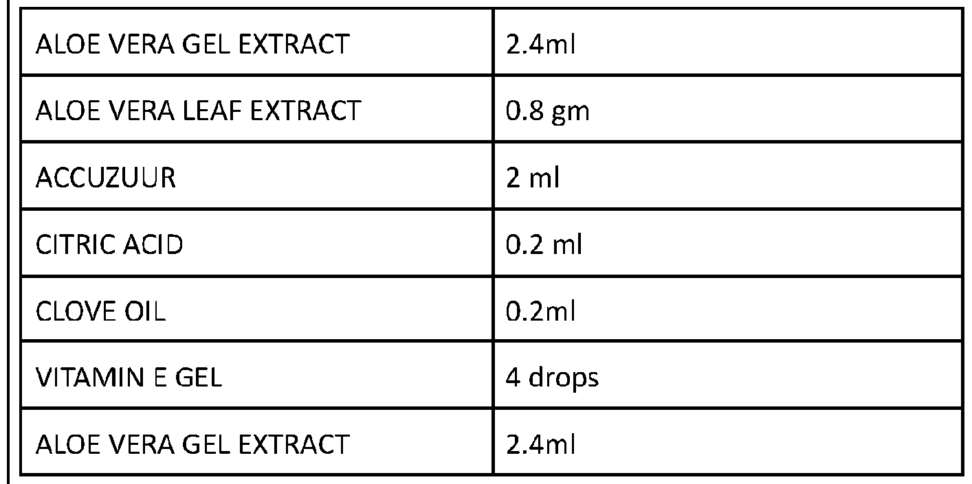
Electrolyte of ALOE ECELL consists of -
- Aloe Vera (ALOE BARBADENSIS MILLER) gel extract Aloe Vera leaf extract
Vitamin E Gel Clove oil
- Accuzuur Citric Acid
• Cathode-
Terminal through which electric current flows out of a polarized electrical gadget, wherein the direction of electric current is opposite to the direction of the flow of the electron.
Properties of a cathode-
- efficient oxidising agent.
- stable when in contact with the electrolyte. in ALOE ECELL, the cathode is Sintered Graphite Electrode
• Anode-
The anode is the positive electrode of a primary cell and is always associated with the oxidation or the release of electrons into the external circuit. Properties of an Anode-
Good conductivity.
Economically viable.
In ALOE ECELL, the anode is the zinc container
It encloses the electrolyte and cathode and is covered by the metal jacket.
• Separate r-
A separator is a permeable membrane placed between a battery's anode and cathode. ... Separators are critical components in liquid electrolyte batteries. A separator generally consists of a polymeric membrane forming a microporous layer. . It must be chemically and electrochemically stable with regard to the electrolyte and electrode materials and mechanically strong enough to withstand the high tension during battery construction. They are important to batteries because their structure and properties considerably affect the battery performance, including the batteries energy and power densities, cycle life, and safety.
Properties of a separator- chemically stable against the electrolyte and electrode materials under the strongly reactive environments when the battery is fully charged. sandwiched between the zinc container wall and the internal container wall. thin enough (not too thin also) to facilitate the battery's energy and power densities. sufficient pore density to hold liquid electrolyte that enables ions to move between the electrodes.
uniformly porous but the pore size should be smaller than the particle size of the electrode components. ionically permeable to provide uniform current density distribution. strong enough to withstand the tension of the winding operations during battery assembly. the electrolyte is able to permanently wet the separator, preserving the cycle life stable over a wide temperature range without curling or puckering, laying completely flat.
In ALOE ECELL, there are two layers of separators to provide tensile strength, impact resistance, durability and uniform charge cycle.
Layer 1 or Outer Layer : Separator Pouch Layer 2 or Inner Layer : Internal Container
• Outer Packaging-
Battery container to hold the complete battery structure, the electrode and the electrolyte which is made up of zinc.
The zinc battery container is enclosed with the Lock seam metal jacket internally lined with the polyethylene layer to provide leak protection, impact resistance and prevents leakage.
Brief description of the drawings:
Figure 1 shows the Sintered Graphite Electrode with the Electrode Holder Ring.
The Sintered Graphite rod is inserted into the electrolyte and the electrode holder ring is pressed against the electrolyte in the container to keep the electrolyte and rod in place forbidding its movement.
Figure 2 shows the three rings which serves three different purposes, known as-
• Leak Proof Seal
• Hold down washer seal with the electrode holder ring
• bottom hold down washer
Figure 2(a) shows Leak proof Ring/Seal
This figure shows Upper most ring namely LEAK PROTECTION RING/SEAL serving as an ANTI LEAKAGE LOCK which will lock the electrolyte and prevent it from spilling around and ruining the devices.
Figure 2(b) shows Hold Down Washer Seal
It holds the electrode and electrolyte preventing it from being displaced and spilling around.
It also provides support to the internal structure of the battery.
Figure 2(c) shows Bottom Hold Down Washer
To provide impact resistance and support to the edges of the zinc container preventing the puncture of the battery.
Figure 2(d) shows Translucent view of the three rings inside the container To give a clear indication of the placement of the rings inside the container.
Figure 3 shows the cross section view of the Internal Container
Internal container is a mesh container by shape which is a porous retainer(by function) made up of plastic having its role in
• Providing tensile strength and support to the overall battery against any external forces
• Walls of the internal container keep the separator in contact with anode and also in place so it does not shrink or collapse in liquid medium electrolyte.
• Pores on the wall of the internal container serves as the connecting medium between the ions of the electrolyte and the separator wall.
• It Provides room for the internal components which holds graphite rod
This container contains
• electrolyte
• Sintered graphite rod
• electrode holder ring
• hold down washer seal
• bottom hold down washer
Figure 3(a) : shows the Internal Container it shows the exact look of the internal container which resembles a mesh container. It is specially designed for being porous and permeable.
Figure 3(b) : Internal container ortho view
It shows the internal container with the internal structures placed in accordance to their utility and place giving a clear indication of the look of the internal container.
Figure 3(c) Translucent view of the internal container with the three rings and sintered graphite electrode with electrode holder ring.
It shows the internal rings placed and how it looks without the internal container.
Figure 4 shows the complete Internal container
Internal container is a mesh container which is a porous retainer(by function) made up of plastic to hold the electrolyte. This figure shows the complete structure of the internal container which is the inner layer of the separator.
Figure 5 shows the separator enclosing the Internal Container and other parts.
This figure showcases the separator paper i.e. ionically permeable wooden kraft paper enclosing the porous internal container which encloses the electrode holder ring, hold down washer seal, bottom hold down washer seal, sintered graphite rod and cathode cup.
Figure 6 shows the cross section of the complete Aloe Ecell Battery.
This figure shows how the Aloe Ecell battery looks from inside.
It shows the battery container enclosed by the Lock Seam Metal Jacket (packaging) lined with polyethylene.
It shows the separator paper enclosing the porous internal container.
Internal container enclosing the cathode cup, electrode holder ring, hold down washer seal, bottom hold down washer seal and sintered graphite rod.
This figure also shows LEAK PROTECTION RING or SEAL serving as an ANTI LEAKAGE LOCK which will lock the electrolyte and prevent it from spilling around and ruining the devices.
Figure 6(a) shows the different layers of the battery cell inside the Metal Seam Jacket.
Thus, this defines various layers of the ALOE ECELL BATTERY. Which are as follows(going inwards)-
LAYER 4 - BATTERY CONTAINER( ZINC ANODE)
LAYER 3 - SEPARATOR POUCH (ionically permeable KRAFT PAPER)
LAYER 2 - INTERNAL CONTAINER (mesh container)
LAYER 1 - ELECTROLYTE figure 6(b) shows the neck setting of the components
This figure is used to clearly indicate the shape of the electrode holder ring and how it helps in holding the electrode and electrolyte in place. This figure clearly depicts the neck of the battery cell specifying the use of each component.
Figure 6(c) shows the wireframe view of the neck setting of the components
This figure is also used to show the usage of various rings in the wireframe view for better understanding.
BATTERY VIEW and Intersection view of the electrode aloe cell
The Figure 7 showcases the cross section of the complete battery highlighting the internal structure of a battery.
Explaining the structure according to the given numbering-
1. Cathode cup or cap with insulating washer This part serves two purposes.
Purpose 1- Keeps the Sintered graphite rod, Electrode Holder Ring at the place.
Purpose 2- Conducts on behalf of the cathode by providing direct connection with the Sintered graphite rod.
2. Battery container and lock seam metal jacket • Battery container is made up of ZINC.
• It acts as the anode for this cell.
• Electrons are collected here.
• Lock Seam Metal Jacket
• This showcases the outline of the cell which is enclosed by a metal jacket internally lined with the polyethylene layer to provide support and will be used for the branding.
• it is the outermost layer of the battery.
• it prevents short circuit of the battery and provides final leak support.
• It is used for displaying the brand's name and other vital instructions.
arator Pouch
• This is the outer layer of the separator known as the separator pouch.
• It is situated between the walls of the Battery Container and Internal Container.
• It is made up of Kraft paper or wooden lined paper. rnal Container
• This is the support system of the cell which is situated on the inner lining of the separator pouch.
• It provides tensile strength and support to the overall battery against any external forces
• It allows the molecules of the electrolyte to pass through and help the separator to be wet.
• It acts like a plastic mesh container which holds the electrolyte, cathode, leak protection ring/seal , electrode holder ring, Hold down washer seal and bottom hold down washer. k Protection Ring or Seal
• This is a sealing cap which works like an ANTI LEAKAGE or SPILLAGE LOCK.
• It prevents the electrolyte from leaking, preventing the ruining of the devices.
• It also prevents any extra passing of molecules that could result in leakage.
• It prevents gassing. de Holder Ring
• It is present on the sintered carbon electrode.
• It provides a tight cap to the electrolyte.
• It keeps the electrolyte and the sintered graphite electrode in place.
• It avoids leakage or spilling of the electrolytes from the centre of the battery or from the place where the sintered graphite electrode is inserted. n Washer Seal
• It provides a support system to the battery being placed at the upper end of the battery.
• It completely packs the internal container leaving only a hole in the middle for filling of the electrolyte and inserting the sintered graphite electrode.
• It provides impact resistance against any horizontal force acting on the container from outside.
• Keeps the sintered graphite rod in the centre. old Down Washer
• It provides a support system to the battery at the bottom.
• It is a Y-SHAPED disk that provides equal support and tensile strength at all edges.
• It provides impact resistance to the battery .
• Y shape supports the flow of electrolyte by providing more space.
• It holds the sintered graphite rod in place and prevents it from touching the bottom surface of the internal container.
• It prevents squeezing of the battery through any external forces.
9. Sintered Graphite Electrode
• It is the cathode.
• It collects electrons.
FIGURE A shows the complete battery.
This section shows ALOE ECELL as a whole (from outside) and explains the external structure of ALOE ECELL BATTERY clearly defining the different parts of the cell and its uses/applications.
Figure A(a) shows the front view of the product This showcases the logo.
Figure A(b) shows the back view of the product
This shows the instructions, QR Code and various warnings on the herbal cell.
Figure A( c) shows the product external dimensions and structure clearly.
This defines the minimum and maximum readings or dimensions of various parts of the battery
Figure B Shows the product clearly identifying its parts. The battery has been divided into 3 parts-
• Part A shows the Metal container
• Part B shows the cathode cap
• Part C shows the lower steel cap
Description of each has been given below clearly.
Figure B(A) depicts PART A-Cylindrical Container
• Internally lined with 2 layers of separators and supporting structures.
• for enclosing the electrolyte, internal structure and the cathode rod.
• Acts as anode.
• Dimensions
• Height = 49.50mm (1.949 inch)
• Material = Zinc
Figure B(B) depicts PART B - Upper Cap also known as Cathode Cup
• Used for closing the part A i.e. cylindrical container
• Used for holding the gel.
• Dimensions
• Height = 1.00mm (0.039 inch)
• Radius = 2.25 mm (0.088 inch)
• Material = Steel
Figure B (C ) depicts PART C-LOWER CAP
• For closing the bottom end.
• To provide proper size.
• To act as anode.
• Dimensions
• Height = 0.10 mm( 0.04 inch)
• Radius = 3.50mm (1.137 inch)
• Material = Steel
Figure B(D) depicts Plastic + Metal Steel Jacket
• Used for branding support and preventing short circuit.
• Dimensions
• Height = 50mm
• Width = 45 mm
• Material = Steel
Objectives of the invention:
1. The invention relates to the primary cell batteries more specifically to the cells containing herbal aqueous electrolyte .
2. The objective of the invention is to provide novel construction of the primary cell which can outstrip the legacy cell zinc carbon batteries
3. Another objective of this battery cell is getting eco friendly batteries which can address the problem of landfills, pollution and diseases due to legacy batteries.
4. The other objective is to lay the foundation of aloe vera herbal batteries and to find an alternative green electrolyte for use.
5. Another objective is that the design increases the efficiency of a battery. 6. Yet another objective is to make a 100% eco- friendly battery which is 1.5x more durable and 10% economical.
7. The objective is to provide a source of income for farmers who grow aloe vera and also reduce the environmental pollution to the extent of 71.6%.
8. Still another objective is to provide an easily biodegradable battery increasing the recycling rate by 19% to 87% .
Claims
1. An electro herbal cell made up of metal container internally lined with a separator pouch and an impact proof internal structure with a graphite rod inserted in the electrolyte which is liquid in nature.
2. An electro herbal cell as claimed in claim 1, comprising of: a. anode selected from Zn which is the cover of the cell; b. a cathode selected from carbon rod or graphite; c. a liquid herbal electrolyte; d. a separator lining ; and d. an internal strong support ensuring better impact resistance to the electrolyte.
3. An electro herbal cell as claimed in claim 2, consists of -
LAYER 5- LOCK SEAM METAL JACKET INTERNALLY LINED WITH POLYETHYLENE.
LAYER 4 - BATTERY CONTAINER( ZINC ANODE)
LAYER 3 - SEPARATOR POUCH
LAYER 2 - INTERNAL CONTAINER (mesh container)
LAYER 1 - ELECTROLYTE
4. An electro herbal cell as claimed in claim 3, consists of INTERNAL CONTAINER WHICH FURTHER CONSISTS OF- leak protection ring; hold down washer seal bottom hold down washer electrode holder ring sintered graphite electrode
5. An electro herbal cell as claimed in claim 1, wherein the electrolyte used is consisting of ingredients comprising of:
 in a ratio of 6:5:1:1:2 for aloe : accuzuur : citric acid : clove oil : vitamin e gel.
6. An electro herbal cell as claimed in claim 4, wherein the aloe used is preferably selected from Aloe barbadensis.
7. An electro herbal cell as claimed in claim 1 , the efficiency was 50% more than any Zinc
carbon battery cell.
8. An electro herbal cell as claimed in claim 4, wherein the vitamin e gel and clove oil used are a preferable preservative for Shelf lives 3 years at 25°C.
9. The aloe cell battery claimed in claim 1, the process relating to the preparation is comprising of
• the internal container i.e. the Plastic Mesh Bucket shaped contained which is a porous retainer) containing the following components in place- leak protection ring or seal hold down washer bottom hold down washer;
• wrap the separator paper around the internal container forming a separator pouch upto the neck of the internal container i.e to the height of hold down washer;
• ensure it is glued to the outer wall of the internal container properly.
• Put this structure inside the Battery container.
• Insert the electrolyte through the hole present in the centre of the hold down washer which is present on the top of the internal container.
• now insert the sintered graphite electrode in the same hole i.e. in the internal container already fitted with the electrode holder ring.
• Tighten the leak protection seal and electrode holder ring
• Fill the resin or asphalt in the spacing above the hold down washer ensuring 50% space is left for the gases to move around preventing expansion and explosion.
• Place the cathode cap with an insulating washer over the top of the sintered graphite rod.
• Ensure the sintered graphite electrode is fitted into the cathode cap and is also fitted in the leak protection ring.
• Cover the structure with the branded printed metal seam jacket internally lined with the polyethylene or polyethylene and paper jacket.
• The battery is ready . Keep the battery still for a minute
9. An electro herbal cell having a shelf life increased by inserting in the layered structure resulting in a efficacy 50% more than the zinc carbon battery cells.
Applications Claiming Priority (2)
| Application Number | Priority Date | Filing Date | Title |
|---|---|---|---|
| IN202011009889 | 2020-03-07 | ||
| IN202011009889 | 2020-03-07 |
Publications (1)
| Publication Number | Publication Date |
|---|---|
| WO2021181165A1 true WO2021181165A1 (en) | 2021-09-16 |
Family
ID=77670546
Family Applications (1)
| Application Number | Title | Priority Date | Filing Date |
|---|---|---|---|
| PCT/IB2021/020012 WO2021181165A1 (en) | 2020-03-07 | 2021-03-05 | Aloe cell and the process |
Country Status (1)
| Country | Link |
|---|---|
| WO (1) | WO2021181165A1 (en) |
Citations (2)
| Publication number | Priority date | Publication date | Assignee | Title |
|---|---|---|---|---|
| US20100112431A1 (en) * | 2003-08-08 | 2010-05-06 | Rovcal Inc. | Separators for alkaline electrochemical cells |
| US20150010833A1 (en) * | 2011-12-14 | 2015-01-08 | Eos Energy Storage, Llc | Electrically rechargeable, metal anode cell and battery systems and methods |
-
2021
- 2021-03-05 WO PCT/IB2021/020012 patent/WO2021181165A1/en active Application Filing
Patent Citations (2)
| Publication number | Priority date | Publication date | Assignee | Title |
|---|---|---|---|---|
| US20100112431A1 (en) * | 2003-08-08 | 2010-05-06 | Rovcal Inc. | Separators for alkaline electrochemical cells |
| US20150010833A1 (en) * | 2011-12-14 | 2015-01-08 | Eos Energy Storage, Llc | Electrically rechargeable, metal anode cell and battery systems and methods |
Similar Documents
| Publication | Publication Date | Title |
|---|---|---|
| CN208637537U (en) | A kind of solid state battery of low interfacial resistance | |
| EP2489086B1 (en) | Cylindrical nickel-zinc cell with positive can | |
| US10637118B2 (en) | Pouched metal-air battery cells | |
| US8752573B2 (en) | Non-aqueous electrolyte secondary battery with filling function, and non-aqueous electrolyte secondary battery and non-aqueous electrolyte filling device used therefor | |
| CN105960718B (en) | Battery case and battery | |
| CN107681190A (en) | The bipolar structure body and battery core of a kind of high-voltage battery | |
| CN109300698A (en) | A kind of lithium-ion capacitor and preparation method thereof | |
| CN208570805U (en) | A kind of end face weld battery convenient for fluid injection | |
| US3592693A (en) | Consumable metal anode with dry electrolytic enclosed in envelope | |
| WO2021181165A1 (en) | Aloe cell and the process | |
| CN201233933Y (en) | Pillar type lithium battery | |
| CN201465812U (en) | Chip omniseal non-solid electrolyte tantalum capacitor | |
| US3694267A (en) | Leakproof closure seal for battery | |
| KR102568421B1 (en) | Membrane electrode assembly and zinc-bromide supercapattery comprising the same | |
| CN207398244U (en) | The cathode gasket of cylindrical lithium ion battery | |
| CN208655822U (en) | A kind of cylinder solid state battery | |
| EP3598547B1 (en) | Water-activated power generating device | |
| CN207183434U (en) | Place the battery of carbon plate structure in a kind of upper strata | |
| CN104538593B (en) | A kind of alkaline storage battery used film covering type nickel electrode and preparation method thereof | |
| CN110676424A (en) | Secondary battery and preparation method thereof | |
| CN110048166B (en) | High-safety lithium ion battery cell structure and preparation method thereof | |
| CN208352437U (en) | From drop internal resistance dry cell | |
| US11909025B2 (en) | Air electrode assemblies incorporating ion exchange materials | |
| CN202333045U (en) | Battery | |
| CN110544794A (en) | High-energy-density lithium ion/sodium ion battery |
Legal Events
| Date | Code | Title | Description |
|---|---|---|---|
| DPE2 | Request for preliminary examination filed before expiration of 19th month from priority date (pct application filed from 20040101) | ||
| 121 | Ep: the epo has been informed by wipo that ep was designated in this application |
Ref document number: 21767624 Country of ref document: EP Kind code of ref document: A1 |
|
| ENP | Entry into the national phase |
Ref document number: 2022565768 Country of ref document: JP Kind code of ref document: A |
|
| NENP | Non-entry into the national phase |
Ref country code: DE |
|
| 122 | Ep: pct application non-entry in european phase |
Ref document number: 21767624 Country of ref document: EP Kind code of ref document: A1 |