WO2021177366A1 - Cage and roller - Google Patents
Cage and roller Download PDFInfo
- Publication number
- WO2021177366A1 WO2021177366A1 PCT/JP2021/008244 JP2021008244W WO2021177366A1 WO 2021177366 A1 WO2021177366 A1 WO 2021177366A1 JP 2021008244 W JP2021008244 W JP 2021008244W WO 2021177366 A1 WO2021177366 A1 WO 2021177366A1
- Authority
- WO
- WIPO (PCT)
- Prior art keywords
- roller
- cage
- rollers
- pair
- axial direction
- Prior art date
Links
Images


Classifications
-
- F—MECHANICAL ENGINEERING; LIGHTING; HEATING; WEAPONS; BLASTING
- F16—ENGINEERING ELEMENTS AND UNITS; GENERAL MEASURES FOR PRODUCING AND MAINTAINING EFFECTIVE FUNCTIONING OF MACHINES OR INSTALLATIONS; THERMAL INSULATION IN GENERAL
- F16C—SHAFTS; FLEXIBLE SHAFTS; ELEMENTS OR CRANKSHAFT MECHANISMS; ROTARY BODIES OTHER THAN GEARING ELEMENTS; BEARINGS
- F16C19/00—Bearings with rolling contact, for exclusively rotary movement
- F16C19/22—Bearings with rolling contact, for exclusively rotary movement with bearing rollers essentially of the same size in one or more circular rows, e.g. needle bearings
- F16C19/24—Bearings with rolling contact, for exclusively rotary movement with bearing rollers essentially of the same size in one or more circular rows, e.g. needle bearings for radial load mainly
- F16C19/26—Bearings with rolling contact, for exclusively rotary movement with bearing rollers essentially of the same size in one or more circular rows, e.g. needle bearings for radial load mainly with a single row of rollers
-
- F—MECHANICAL ENGINEERING; LIGHTING; HEATING; WEAPONS; BLASTING
- F16—ENGINEERING ELEMENTS AND UNITS; GENERAL MEASURES FOR PRODUCING AND MAINTAINING EFFECTIVE FUNCTIONING OF MACHINES OR INSTALLATIONS; THERMAL INSULATION IN GENERAL
- F16C—SHAFTS; FLEXIBLE SHAFTS; ELEMENTS OR CRANKSHAFT MECHANISMS; ROTARY BODIES OTHER THAN GEARING ELEMENTS; BEARINGS
- F16C19/00—Bearings with rolling contact, for exclusively rotary movement
- F16C19/22—Bearings with rolling contact, for exclusively rotary movement with bearing rollers essentially of the same size in one or more circular rows, e.g. needle bearings
- F16C19/24—Bearings with rolling contact, for exclusively rotary movement with bearing rollers essentially of the same size in one or more circular rows, e.g. needle bearings for radial load mainly
-
- F—MECHANICAL ENGINEERING; LIGHTING; HEATING; WEAPONS; BLASTING
- F16—ENGINEERING ELEMENTS AND UNITS; GENERAL MEASURES FOR PRODUCING AND MAINTAINING EFFECTIVE FUNCTIONING OF MACHINES OR INSTALLATIONS; THERMAL INSULATION IN GENERAL
- F16C—SHAFTS; FLEXIBLE SHAFTS; ELEMENTS OR CRANKSHAFT MECHANISMS; ROTARY BODIES OTHER THAN GEARING ELEMENTS; BEARINGS
- F16C19/00—Bearings with rolling contact, for exclusively rotary movement
- F16C19/22—Bearings with rolling contact, for exclusively rotary movement with bearing rollers essentially of the same size in one or more circular rows, e.g. needle bearings
- F16C19/44—Needle bearings
- F16C19/46—Needle bearings with one row or needles
- F16C19/463—Needle bearings with one row or needles consisting of needle rollers held in a cage, i.e. subunit without race rings
-
- F—MECHANICAL ENGINEERING; LIGHTING; HEATING; WEAPONS; BLASTING
- F16—ENGINEERING ELEMENTS AND UNITS; GENERAL MEASURES FOR PRODUCING AND MAINTAINING EFFECTIVE FUNCTIONING OF MACHINES OR INSTALLATIONS; THERMAL INSULATION IN GENERAL
- F16C—SHAFTS; FLEXIBLE SHAFTS; ELEMENTS OR CRANKSHAFT MECHANISMS; ROTARY BODIES OTHER THAN GEARING ELEMENTS; BEARINGS
- F16C19/00—Bearings with rolling contact, for exclusively rotary movement
- F16C19/22—Bearings with rolling contact, for exclusively rotary movement with bearing rollers essentially of the same size in one or more circular rows, e.g. needle bearings
- F16C19/44—Needle bearings
- F16C19/46—Needle bearings with one row or needles
- F16C19/466—Needle bearings with one row or needles comprising needle rollers and an outer ring, i.e. subunit without inner ring
-
- F—MECHANICAL ENGINEERING; LIGHTING; HEATING; WEAPONS; BLASTING
- F16—ENGINEERING ELEMENTS AND UNITS; GENERAL MEASURES FOR PRODUCING AND MAINTAINING EFFECTIVE FUNCTIONING OF MACHINES OR INSTALLATIONS; THERMAL INSULATION IN GENERAL
- F16C—SHAFTS; FLEXIBLE SHAFTS; ELEMENTS OR CRANKSHAFT MECHANISMS; ROTARY BODIES OTHER THAN GEARING ELEMENTS; BEARINGS
- F16C29/00—Bearings for parts moving only linearly
- F16C29/04—Ball or roller bearings
- F16C29/048—Ball or roller bearings with thin walled races, e.g. tracks of sheet metal
-
- F—MECHANICAL ENGINEERING; LIGHTING; HEATING; WEAPONS; BLASTING
- F16—ENGINEERING ELEMENTS AND UNITS; GENERAL MEASURES FOR PRODUCING AND MAINTAINING EFFECTIVE FUNCTIONING OF MACHINES OR INSTALLATIONS; THERMAL INSULATION IN GENERAL
- F16C—SHAFTS; FLEXIBLE SHAFTS; ELEMENTS OR CRANKSHAFT MECHANISMS; ROTARY BODIES OTHER THAN GEARING ELEMENTS; BEARINGS
- F16C33/00—Parts of bearings; Special methods for making bearings or parts thereof
- F16C33/30—Parts of ball or roller bearings
- F16C33/34—Rollers; Needles
-
- F—MECHANICAL ENGINEERING; LIGHTING; HEATING; WEAPONS; BLASTING
- F16—ENGINEERING ELEMENTS AND UNITS; GENERAL MEASURES FOR PRODUCING AND MAINTAINING EFFECTIVE FUNCTIONING OF MACHINES OR INSTALLATIONS; THERMAL INSULATION IN GENERAL
- F16C—SHAFTS; FLEXIBLE SHAFTS; ELEMENTS OR CRANKSHAFT MECHANISMS; ROTARY BODIES OTHER THAN GEARING ELEMENTS; BEARINGS
- F16C33/00—Parts of bearings; Special methods for making bearings or parts thereof
- F16C33/30—Parts of ball or roller bearings
- F16C33/46—Cages for rollers or needles
- F16C33/4617—Massive or moulded cages having cage pockets surrounding the rollers, e.g. machined window cages
- F16C33/4623—Massive or moulded cages having cage pockets surrounding the rollers, e.g. machined window cages formed as one-piece cages, i.e. monoblock cages
- F16C33/4635—Massive or moulded cages having cage pockets surrounding the rollers, e.g. machined window cages formed as one-piece cages, i.e. monoblock cages made from plastic, e.g. injection moulded window cages
-
- F—MECHANICAL ENGINEERING; LIGHTING; HEATING; WEAPONS; BLASTING
- F16—ENGINEERING ELEMENTS AND UNITS; GENERAL MEASURES FOR PRODUCING AND MAINTAINING EFFECTIVE FUNCTIONING OF MACHINES OR INSTALLATIONS; THERMAL INSULATION IN GENERAL
- F16C—SHAFTS; FLEXIBLE SHAFTS; ELEMENTS OR CRANKSHAFT MECHANISMS; ROTARY BODIES OTHER THAN GEARING ELEMENTS; BEARINGS
- F16C33/00—Parts of bearings; Special methods for making bearings or parts thereof
- F16C33/30—Parts of ball or roller bearings
- F16C33/46—Cages for rollers or needles
- F16C33/467—Details of individual pockets, e.g. shape or roller retaining means
- F16C33/4682—Details of individual pockets, e.g. shape or roller retaining means of the end walls, e.g. interaction with the end faces of the rollers
-
- F—MECHANICAL ENGINEERING; LIGHTING; HEATING; WEAPONS; BLASTING
- F16—ENGINEERING ELEMENTS AND UNITS; GENERAL MEASURES FOR PRODUCING AND MAINTAINING EFFECTIVE FUNCTIONING OF MACHINES OR INSTALLATIONS; THERMAL INSULATION IN GENERAL
- F16C—SHAFTS; FLEXIBLE SHAFTS; ELEMENTS OR CRANKSHAFT MECHANISMS; ROTARY BODIES OTHER THAN GEARING ELEMENTS; BEARINGS
- F16C33/00—Parts of bearings; Special methods for making bearings or parts thereof
- F16C33/30—Parts of ball or roller bearings
- F16C33/58—Raceways; Race rings
- F16C33/588—Races of sheet metal
-
- F—MECHANICAL ENGINEERING; LIGHTING; HEATING; WEAPONS; BLASTING
- F16—ENGINEERING ELEMENTS AND UNITS; GENERAL MEASURES FOR PRODUCING AND MAINTAINING EFFECTIVE FUNCTIONING OF MACHINES OR INSTALLATIONS; THERMAL INSULATION IN GENERAL
- F16C—SHAFTS; FLEXIBLE SHAFTS; ELEMENTS OR CRANKSHAFT MECHANISMS; ROTARY BODIES OTHER THAN GEARING ELEMENTS; BEARINGS
- F16C2226/00—Joining parts; Fastening; Assembling or mounting parts
- F16C2226/50—Positive connections
- F16C2226/62—Positive connections with pins, bolts or dowels
-
- F—MECHANICAL ENGINEERING; LIGHTING; HEATING; WEAPONS; BLASTING
- F16—ENGINEERING ELEMENTS AND UNITS; GENERAL MEASURES FOR PRODUCING AND MAINTAINING EFFECTIVE FUNCTIONING OF MACHINES OR INSTALLATIONS; THERMAL INSULATION IN GENERAL
- F16C—SHAFTS; FLEXIBLE SHAFTS; ELEMENTS OR CRANKSHAFT MECHANISMS; ROTARY BODIES OTHER THAN GEARING ELEMENTS; BEARINGS
- F16C2226/00—Joining parts; Fastening; Assembling or mounting parts
- F16C2226/50—Positive connections
- F16C2226/70—Positive connections with complementary interlocking parts
-
- F—MECHANICAL ENGINEERING; LIGHTING; HEATING; WEAPONS; BLASTING
- F16—ENGINEERING ELEMENTS AND UNITS; GENERAL MEASURES FOR PRODUCING AND MAINTAINING EFFECTIVE FUNCTIONING OF MACHINES OR INSTALLATIONS; THERMAL INSULATION IN GENERAL
- F16C—SHAFTS; FLEXIBLE SHAFTS; ELEMENTS OR CRANKSHAFT MECHANISMS; ROTARY BODIES OTHER THAN GEARING ELEMENTS; BEARINGS
- F16C2360/00—Engines or pumps
- F16C2360/18—Camshafts
-
- F—MECHANICAL ENGINEERING; LIGHTING; HEATING; WEAPONS; BLASTING
- F16—ENGINEERING ELEMENTS AND UNITS; GENERAL MEASURES FOR PRODUCING AND MAINTAINING EFFECTIVE FUNCTIONING OF MACHINES OR INSTALLATIONS; THERMAL INSULATION IN GENERAL
- F16C—SHAFTS; FLEXIBLE SHAFTS; ELEMENTS OR CRANKSHAFT MECHANISMS; ROTARY BODIES OTHER THAN GEARING ELEMENTS; BEARINGS
- F16C2360/00—Engines or pumps
- F16C2360/22—Internal combustion engines
-
- F—MECHANICAL ENGINEERING; LIGHTING; HEATING; WEAPONS; BLASTING
- F16—ENGINEERING ELEMENTS AND UNITS; GENERAL MEASURES FOR PRODUCING AND MAINTAINING EFFECTIVE FUNCTIONING OF MACHINES OR INSTALLATIONS; THERMAL INSULATION IN GENERAL
- F16C—SHAFTS; FLEXIBLE SHAFTS; ELEMENTS OR CRANKSHAFT MECHANISMS; ROTARY BODIES OTHER THAN GEARING ELEMENTS; BEARINGS
- F16C2360/00—Engines or pumps
- F16C2360/44—Centrifugal pumps
-
- F—MECHANICAL ENGINEERING; LIGHTING; HEATING; WEAPONS; BLASTING
- F16—ENGINEERING ELEMENTS AND UNITS; GENERAL MEASURES FOR PRODUCING AND MAINTAINING EFFECTIVE FUNCTIONING OF MACHINES OR INSTALLATIONS; THERMAL INSULATION IN GENERAL
- F16C—SHAFTS; FLEXIBLE SHAFTS; ELEMENTS OR CRANKSHAFT MECHANISMS; ROTARY BODIES OTHER THAN GEARING ELEMENTS; BEARINGS
- F16C2361/00—Apparatus or articles in engineering in general
- F16C2361/65—Gear shifting, change speed gear, gear box
Definitions
- the present invention relates to, for example, a cage and roller mounted on a transmission gear support portion and a shaft support portion of a vehicle, a roller follower for an engine, a roller follower for a fuel pump, and the like.
- radial needle bearings are often used for rotating parts of various industrial machines and transmissions of automobiles.
- bearings that can be used under severe conditions are required as the output and speed of automobiles increase.
- Patent Documents 1 to 3 disclose a cage having a pillar portion in a gap on the outer diameter side or the inner diameter side of the roller pitch circle diameter between a plurality of rollers arranged in a cylindrical shape.
- the number of rollers that is close to the total roller bearings that do not have a cage can be inserted while preventing the rollers from coming into contact with each other, and the load capacity can be increased.
- Patent Document 4 proposes a cage and roller in which a pillar portion is formed on the outer ring raceway surface side of the cage, and a plurality of rollers are arranged in a pocket portion between adjacent pillar portions. ..
- the roller fall-off prevention pillar is formed in the gap between the two adjacent rollers and the outer ring raceway surface in one pocket, it is possible to prevent the rollers from falling off to the outside of the cage. At the same time, a high load capacity can be realized.
- Japanese Patent No. 4618915 Japanese Patent Application Laid-Open No. 2007-187287 Japanese Patent Application Laid-Open No. 2013-185640 Japanese Patent Application Laid-Open No. 2016-156472
- the present invention has been made in view of the above-mentioned problems, and an object of the present invention is to provide a cage and roller capable of increasing the load capacity while suppressing an increase in bearing torque.
- the above object of the present invention is achieved by the following configuration.
- the plurality of rollers have protrusions on both end faces in the axial direction.
- the pair of annular plates have a plurality of holes for engaging the protrusions of the plurality of rollers, and the plurality of rollers are rotatably held in a non-contact state with each other.
- the protrusions formed on both end faces of the rollers and the holes formed in the pair of annular plates are engaged with each other, and the plurality of rollers are not in contact with each other by the pair of annular plates. Since it is held rotatably, it is possible to increase the load capacity while suppressing an increase in bearing torque.
- FIG. 2 is a cross-sectional view taken along the line III-III of FIG. It is sectional drawing which shows the part of the cage and roller which concerns on 2nd Embodiment of this invention in an enlarged manner. It is sectional drawing which shows the part of the cage and roller which concerns on 3rd Embodiment of this invention in an enlarged manner. It is sectional drawing which shows the part of the cage and roller which concerns on 4th Embodiment of this invention in an enlarged manner.
- the cage and roller 10 according to the first embodiment of the present invention will be described with reference to FIGS. 1 to 3.
- the axial direction, the radial direction, the circumferential direction, the outer diameter side and the inner diameter side are the axial direction, the radial direction, the circumferential direction, and the outside of the cylindrical cage and roller. Indicates the diameter side and the inner diameter side.
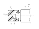
- the cage and roller 10 of the present embodiment is arranged on both sides of a plurality of rollers 11 arranged in a cylindrical shape and a plurality of rollers 11 in the axial direction, and rotates the plurality of rollers 11. It has a pair of annular plates 12 that are freely held, and a plurality of (four in this embodiment) pillar portions 13 that connect the pair of annular plates 12 in the axial direction.
- convex spherical protrusions 11a projecting outward in the axial direction are formed on both end faces in the axial direction of the rollers 11.
- the protrusion 11a is formed by scraping both ends of the columnar roller 11 or performing plastic working.
- the pair of annular plates 12 are arranged so as to sandwich both ends of the plurality of rollers 11 in the axial direction, and the pair of annular plates 12 are connected in the axial direction by the four pillar portions 13. That is, in the present embodiment, the annular plate 12 and the pillar portion 13 are integrally molded with synthetic resin to form the cage 14.
- the radial wall thickness of the pillar portion 13 is the same as the radial wall thickness of the annular plate 12, and the outer diameter surface of the pillar portion 13 is connected flush with the outer peripheral surface of the annular plate 12, and the inner diameter of the pillar portion 13 is formed. The surface is connected flush with the inner peripheral surface of the annular plate 12.
- the pillar portion 13 is configured so as not to come into contact with the roller 11.
- the number of pillars 13 is not limited to four, and if the strength of the cage 14 can be secured, it may be two or more, and it may be 1/2 or less (preferably less than 1/3) of the number of rollers 11.
- the pillar portions 13 are preferably arranged at substantially equal intervals in the circumferential direction, but may not be arranged at substantially equal intervals.
- a plurality of holes 12a for engaging the protrusions 11a of each roller 11 are formed at substantially equal intervals in the circumferential direction in the region of the pair of annular plates 12 on the inner end faces in the axial direction except for the pillars 13.
- the hole portion 12a is formed in a concave spherical shape.
- the circumferential distance between the holes 12a adjacent to each other in the circumferential direction is set to be slightly larger than the diameter D of the roller 11. Specifically, there is a slight circumferential gap between the protrusion 11a and the hole 12a, and the gap causes the roller 11 to be slightly displaced in the circumferential direction with respect to the hole 12a. Is possible.
- the circumferential spacing of the holes 12a is set so that the rollers 11 that are displaced in the circumferential direction do not come into contact with each other. Therefore, the plurality of holes 12a of the pair of annular plates 12 can rotatably hold the plurality of rollers 11 in a non-contact state with each other. Further, the radius of curvature R1 of the convex spherical surface of the protrusion 11a is set smaller than the radius of curvature R2 of the concave spherical surface of the hole 12a (R1 ⁇ R2).
- the center of the convex spherical surface of the protrusion 11a is located on the rotation center axis (rotation axis) of the roller 11, and the center of the concave spherical surface of the hole 12a is the PCD (pitch circle diameter) of the plurality of rollers 11. Located on top.
- an insertion groove 12b is formed along the radial direction to facilitate inserting the roller 11 into the hole 12a.
- the insertion groove 12b is formed in a semi-cylindrical shape that is arcuate when viewed from the outer diameter side, and is formed at a depth shallower than that of the hole portion 12a.
- the axial distance L2 between the insertion grooves 12b is set to be smaller than the axial length L1 of the rollers 11 (L2 ⁇ L1).
- the axial length L1 of the roller 11 is set to be smaller than the axial length L3 of the cage 14 (L1 ⁇ L3), and each hole 12a does not penetrate the annular plate 12 in the axial direction. Therefore, the roller 11 is held inside the cage 14. Therefore, the protrusion 11a, which is the axial end of the roller 11, does not protrude from the axial outer end surface of the annular plate 12 (the axial end of the cage 14).
- the protrusions 11a formed on both end faces of the rollers 11 and the holes 12a formed in the pair of annular plates 12 are engaged with each other. Since the pair of annular plates 12 rotatably hold the plurality of rollers 11 in a non-contact state with each other, an increase in the bearing torque of the cage and roller 10 can be suppressed, and seizure of the rollers 11 and a decrease in the allowable rotation speed can be prevented. can. Further, since it is not necessary to provide a pillar portion between all the adjacent rollers 11, the number of rollers 11 can be made close to the total roller bearing, and the load capacity of the cage and roller 10 can be increased. ..
- the plurality of rollers 11 are held by the cage 14 by engaging the protrusion 11a of the rollers 11 with the holes 12a of the pair of annular plates 12.
- the roller 11 can be prevented from falling off from the cage 14 without providing a roller fall-off prevention pillar or a roller fall-off prevention tool.
- the radius of curvature of the convex spherical surface of the protrusion 11a of the roller 11 is set to be smaller than the radius of curvature of the concave spherical surface of the hole 12a of the annular plate 12, so that the protrusion The portion 11a and the hole portion 12a come into point contact at one point.
- the frictional resistance between the roller 11 and the annular plate 12 can be suppressed to a minimum, and an increase in the bearing torque of the cage and roller 10 can be further suppressed.
- the cage 14 is formed of synthetic resin, the cage 14 is elastically deformed when the rollers 11 are incorporated into the cage 14. Therefore, the roller 11 can be easily incorporated into the cage 14, and the roller 11 can be prevented from falling off after the assembly. Further, since each hole 12a does not penetrate the annular plate 12 in the axial direction, it is possible to suppress a decrease in strength of the annular plate 12. Further, since the protrusion 11a does not protrude from the axial outer end surface of the annular plate 12 and the axial outer end surface of the annular plate 12 is formed into a planar shape, the rollers 11 and the annular shape are formed when the cage and roller 10 is used. A part of the plate 12 is prevented from interfering with a member axially adjacent to the cage 14.
- the insertion groove 12b is formed at the outer diameter side end of each hole 12a of the annular plate 12, the elasticity of the annular plate 12 when the roller 11 is inserted is formed. The amount of deformation is small, and the roller 11 can be easily inserted into the hole 12a.
- elliptical spherical protrusions 11c projecting outward in the axial direction are formed on both axially end surfaces of the rollers 11, and a pair of annular plates 12
- An elliptical spherical hole 12c for engaging the protrusion 11c of the roller 11 is formed on the inner end surface in the axial direction of the roller 11.
- the long axis of both ellipses of the hole 12c and the protrusion 11c is in the same direction as the axial direction of the roller 11, and the elliptical shape (minor diameter) of the hole 12c is the ellipse (minor diameter) of the protrusion 11c. Is set smaller than.
- the insertion groove 12b may be formed in the annular plate 12 as in the first embodiment.
- the engagement width between the protrusion 11c of the roller 11 and the hole 12c of the annular plate 12 in the axial direction is larger than that of the first embodiment, so that the cage is a cage. It is possible to further prevent the 11 from falling off from the 14th.
- Other configurations and effects are the same as those in the first embodiment.
- substantially conical trapezoidal protrusions 11d projecting outward in the axial direction are formed on both axially end surfaces of the rollers 11, and a pair of annular plates are formed.
- a substantially conical trapezoidal hole portion 12d for engaging the protrusion 11d of the roller 11 is formed on the inner end surface of the 12 in the axial direction.
- the insertion groove 12b may be formed in the annular plate 12 as in the first embodiment.
- the engagement width between the protrusion 11d of the roller 11 and the hole 12d of the annular plate 12 in the axial direction is larger than that of the first embodiment, so that the cage is a cage. It is possible to further prevent the 11 from falling off from the 14th.
- Other configurations and effects are the same as those in the first embodiment.
- conical protrusions 11e projecting outward in the axial direction are formed on both end faces in the axial direction of the rollers 11, and a pair of annular plates 12 are formed.
- a conical hole portion 12e for engaging the protrusion 11e of the roller 11 is formed on the inner end surface in the axial direction.
- the insertion groove 12b may be formed in the annular plate 12 as in the first embodiment.
- the engagement width between the protrusion 11e of the roller 11 and the hole 12e of the annular plate 12 in the axial direction is larger than that of the first embodiment, so that the cage is a cage. It is possible to further prevent the 11 from falling off from the 14th.
- Other configurations and effects are the same as those in the first embodiment.
- ribs 12f protruding outward in the radial direction are formed on the outer peripheral surfaces of the pair of annular plates 12 over the entire circumference. Then, the cage 14 is used for outer ring guidance by making the outer peripheral surface of the rib 12f face the outer ring raceway surface with a slight gap.
- the ribs 12f protruding outward in the radial direction are formed on the outer peripheral surfaces of the pair of annular plates 12, so that rattling in the radial direction of the cage 14 can be suppressed. Thereby, the roller 11 can be further prevented from falling off from the cage 14.
- Other configurations and effects are the same as those in the first embodiment.
- the cage and roller 10F of the present embodiment has two rows of rollers 11 of the cage and roller 10 of the first embodiment.
- the number of rows of the rollers 11 is not limited to two, and may be three or more. Other configurations and effects are the same as those in the first embodiment.
- the cage and roller 20 of the present embodiment is arranged on both sides of the plurality of rollers 21 arranged in a cylindrical shape and the plurality of rollers 21 in the axial direction, and holds the plurality of rollers 21 rotatably. It has a pair of annular plates 22 and a pair of annular plates 22.
- columnar protrusions 21a projecting outward in the axial direction are formed on both end faces in the axial direction of the rollers 21.
- the protrusion 21a is formed at the axial position of the roller 21.
- the protrusion 21a is formed integrally with the roller 21 by scraping both ends of the columnar roller 21 or performing plastic working.
- the pair of annular plates 22 are configured to be separate from each other, and are arranged so as to sandwich both ends in the axial direction of the plurality of rollers 21. That is, the pair of annular plates 22 do not have pillars that are axially connected to each other.
- the annular plate 22 may be made of metal or synthetic resin.
- a plurality of holes 22a for engaging the protrusions 21a of each roller 21 are formed at substantially equal intervals in the circumferential direction.
- the hole portion 22a is a through hole that penetrates the annular plate 22 in the axial direction.
- the circumferential distance between the holes 22a adjacent to each other in the circumferential direction is set to be slightly larger than the diameter of the roller 21. Therefore, the plurality of holes 22a of the pair of annular plates 22 can rotatably hold the plurality of rollers 21 in a non-contact state with each other.
- the cage and roller 20 of the present embodiment does not have a pillar portion for connecting the pair of annular plates 22, the cage and roller 20 is incorporated into the shell type outer ring 25 after combining the plurality of rollers 21 and the pair of annular plates 22. Is done. Then, at the time of use, the shaft 26 is inserted into the cage and roller 20. Since the axial dimension of the protrusion 21a is set smaller than the axial dimension of the hole 22a (same as the axial dimension of the annular plate 22), the protrusion 21a protrudes from the axial outer end surface of the annular plate 22. Therefore, it is prevented from coming into contact with the shell type outer ring 25.
- the protrusions 21a formed on both end faces of the rollers 21 and the holes 22a formed in the pair of annular plates 22 are engaged with each other. Since the pair of annular plates 22 rotatably hold the plurality of rollers 21 in a non-contact state with each other, an increase in the bearing torque of the cage and roller 20 can be suppressed, and seizure and allowable rotation of the rollers 21 can be suppressed. It is possible to prevent the number from decreasing. Further, since it is not necessary to provide a pillar portion for connecting the pair of annular plates 22, the number of rollers 21 can be made close to the total roller bearings, and the load capacity of the cage and roller 20 can be increased.
- the annular plate and the pillar are made of resin and are made of resin.
- the protrusion is columnar and is formed at the axial position of the roller.
- the cage and roller according to (4), wherein the hole is a through hole that penetrates the annular plate in the axial direction.
- the protrusions formed on both end faces of the rollers and the holes formed in the pair of annular plates are engaged with each other, and the plurality of rollers are not in contact with each other by the pair of annular plates. Since it is held rotatably, it is possible to increase the load capacity while suppressing an increase in bearing torque.
Abstract
A cage and roller having a plurality of rollers arranged in a cylindrical shape, a pair of annular plates that are arranged at both sides of the plurality of rollers in the axial direction, and that retain the plurality of rollers, and a plurality of pillars connecting the pair of annular plates. Protruding parts protruding in the axial direction are formed at both end surfaces in the axial direction of the plurality of rollers. A plurality of holes for engaging the protruding parts of the plurality of rollers are formed in the pair of annular plates. The pair of annular plates retain the plurality of rollers in a state in which the plurality of rollers can rotate freely without touching each other.
Description
本発明は、例えば、車両の変速ギア支持部及びシャフト支持部、エンジン用ローラフォロアや燃料ポンプ用ローラフォロア等に装着されるケージアンドローラに関する。
The present invention relates to, for example, a cage and roller mounted on a transmission gear support portion and a shaft support portion of a vehicle, a roller follower for an engine, a roller follower for a fuel pump, and the like.
近時、各種産業機械や自動車の変速機(トランスミッション)等の回転部分には、ラジアルニードル軸受が多用されている。例えば、トランスミッションに使用されるラジアルニードル軸受においては、自動車の高出力化及び高速化に伴って、厳しい条件下で使用可能な軸受が要求されている。
Recently, radial needle bearings are often used for rotating parts of various industrial machines and transmissions of automobiles. For example, in radial needle bearings used in transmissions, bearings that can be used under severe conditions are required as the output and speed of automobiles increase.
例えば、特許文献1~3には、円筒状に配列された複数のころ間におけるころピッチ円直径よりも外径側又は内径側の隙間に柱部を備える保持器が開示されている。これらの保持器を用いたころ軸受は、ころ同士の接触を防止しつつ、保持器を有しない総ころ軸受に近いころ本数を挿入することができ、負荷容量を増加させることができる。
For example, Patent Documents 1 to 3 disclose a cage having a pillar portion in a gap on the outer diameter side or the inner diameter side of the roller pitch circle diameter between a plurality of rollers arranged in a cylindrical shape. In roller bearings using these cages, the number of rollers that is close to the total roller bearings that do not have a cage can be inserted while preventing the rollers from coming into contact with each other, and the load capacity can be increased.
また、特許文献4には、保持器の外輪軌道面側に柱部が形成されており、隣り合う柱部間のポケット部に、複数のころが配置されているケージアンドローラが提案されている。上記ケージアンドローラでは、1つのポケット内で隣接する2本のころと外輪軌道面との隙間に、ころ脱落防止柱が形成されているため、ころが保持器の外側に脱落することを防止できるとともに、高負荷容量を実現できる。
Further, Patent Document 4 proposes a cage and roller in which a pillar portion is formed on the outer ring raceway surface side of the cage, and a plurality of rollers are arranged in a pocket portion between adjacent pillar portions. .. In the cage and roller, since the roller fall-off prevention pillar is formed in the gap between the two adjacent rollers and the outer ring raceway surface in one pocket, it is possible to prevent the rollers from falling off to the outside of the cage. At the same time, a high load capacity can be realized.
しかしながら、上記特許文献1~3に記載のころ軸受をタペットローラ等のような小さな部品に適用しようとした場合、ころが小径となるため、外輪軌道面又は内輪軌道面ところとの隙間が極めて小さくなり、上記隙間に柱を形成することが困難になる。また、上記隙間に柱を配置するために、柱を細く形成すると、保持器の強度を確保することが困難である。さらに、上記特許文献1~3に記載のころ軸受では、ころ同士は接触しないが、ころの転動面と柱が接触した状態でころが回転するため、ころと柱との間に摩擦が発生し、軸受トルクの上昇が懸念される。
However, when the roller bearings described in Patent Documents 1 to 3 are applied to small parts such as tappet rollers, the diameter of the rollers is small, so that the gap between the outer ring raceway surface or the inner ring raceway surface is extremely small. Therefore, it becomes difficult to form a pillar in the gap. Further, if the pillars are formed thin in order to arrange the pillars in the gap, it is difficult to secure the strength of the cage. Further, in the roller bearings described in Patent Documents 1 to 3, the rollers do not contact each other, but the rollers rotate in a state where the rolling surface of the rollers and the columns are in contact with each other, so that friction occurs between the rollers and the columns. However, there is a concern that the bearing torque will increase.
また、上記特許文献4に記載のケージアンドローラでは、外径側へのころの脱落は防止できるものの、出荷時等には内径側への脱落を防止するためにころ脱落防止具が必要となり、部品点数の増加によりコストアップになるという問題点がある。さらに、このケージアンドローラでは、転動時に1つのポケット内でころ同士が接触するため、軸受トルクの上昇、ころの焼き付き、及び許容回転数の低下が懸念される。
Further, in the cage and roller described in Patent Document 4, although it is possible to prevent the rollers from falling off to the outer diameter side, a roller drop prevention tool is required to prevent the rollers from falling off to the inner diameter side at the time of shipment. There is a problem that the cost increases due to the increase in the number of parts. Further, in this cage and roller, since the rollers come into contact with each other in one pocket when rolling, there is a concern that the bearing torque may increase, the rollers may seize, and the allowable rotation speed may decrease.
本発明は、前述した課題に鑑みてなされたものであり、その目的は、軸受トルクの上昇を抑制しながら負荷容量の増加を図ることができるケージアンドローラを提供することにある。
The present invention has been made in view of the above-mentioned problems, and an object of the present invention is to provide a cage and roller capable of increasing the load capacity while suppressing an increase in bearing torque.
本発明の上記目的は、下記の構成により達成される。
円筒状に配列された複数のころと、
前記複数のころの軸方向両側に配置され、前記複数のころを保持する一対の環状板と、を有するケージアンドローラであって、
前記複数のころは、軸方向両端面に突起部を有し、
前記一対の環状板は、前記複数のころの前記突起部を係合させる複数の穴部を有し、前記複数のころを互いに非接触の状態で回転自在に保持する、ケージアンドローラ。 The above object of the present invention is achieved by the following configuration.
Multiple rollers arranged in a cylindrical shape,
A cage and roller having a pair of annular plates arranged on both sides in the axial direction of the plurality of rollers and holding the plurality of rollers.
The plurality of rollers have protrusions on both end faces in the axial direction.
The pair of annular plates have a plurality of holes for engaging the protrusions of the plurality of rollers, and the plurality of rollers are rotatably held in a non-contact state with each other.
本発明によれば、ころの両端面に形成された突起部と、一対の環状板に形成された穴部とを係合させて、一対の環状板により複数のころを互いに非接触の状態で回転自在に保持するため、軸受トルクの上昇を抑制しながら負荷容量の増加を図ることができる。
According to the present invention, the protrusions formed on both end faces of the rollers and the holes formed in the pair of annular plates are engaged with each other, and the plurality of rollers are not in contact with each other by the pair of annular plates. Since it is held rotatably, it is possible to increase the load capacity while suppressing an increase in bearing torque.
以下、本発明に係るケージアンドローラについて、図面に基づいて詳細に説明する。なお、本発明は、以下に説明する実施形態に限定されるものではなく、本発明の要旨を逸脱しない範囲において適宜変更可能である。
Hereinafter, the cage and roller according to the present invention will be described in detail with reference to the drawings. The present invention is not limited to the embodiments described below, and can be appropriately modified without departing from the gist of the present invention.
(第1実施形態)
まず、図1~図3を参照して、本発明の第1実施形態に係るケージアンドローラ10について説明する。なお、以下の説明において、特に記載がない場合には、軸方向、径方向、周方向、外径側及び内径側とは、円筒状のケージアンドローラの軸方向、径方向、周方向、外径側及び内径側を示す。 (First Embodiment)
First, the cage androller 10 according to the first embodiment of the present invention will be described with reference to FIGS. 1 to 3. In the following description, unless otherwise specified, the axial direction, the radial direction, the circumferential direction, the outer diameter side and the inner diameter side are the axial direction, the radial direction, the circumferential direction, and the outside of the cylindrical cage and roller. Indicates the diameter side and the inner diameter side.
まず、図1~図3を参照して、本発明の第1実施形態に係るケージアンドローラ10について説明する。なお、以下の説明において、特に記載がない場合には、軸方向、径方向、周方向、外径側及び内径側とは、円筒状のケージアンドローラの軸方向、径方向、周方向、外径側及び内径側を示す。 (First Embodiment)
First, the cage and
本実施形態のケージアンドローラ10は、図1及び図2に示すように、円筒状に配列された複数のころ11と、複数のころ11の軸方向両側に配置され、複数のころ11を回転自在に保持する一対の環状板12と、一対の環状板12を軸方向に連結する複数(本実施形態では4本)の柱部13と、を有する。
As shown in FIGS. 1 and 2, the cage and roller 10 of the present embodiment is arranged on both sides of a plurality of rollers 11 arranged in a cylindrical shape and a plurality of rollers 11 in the axial direction, and rotates the plurality of rollers 11. It has a pair of annular plates 12 that are freely held, and a plurality of (four in this embodiment) pillar portions 13 that connect the pair of annular plates 12 in the axial direction.
図3に示すように、ころ11の軸方向両端面には、その軸方向外側に突出する凸球面状の突起部11aがそれぞれ形成されている。突起部11aは、円柱状のころ11の両端部を削る、或いは塑性加工を施すことによって形成されている。
As shown in FIG. 3, convex spherical protrusions 11a projecting outward in the axial direction are formed on both end faces in the axial direction of the rollers 11. The protrusion 11a is formed by scraping both ends of the columnar roller 11 or performing plastic working.
一対の環状板12は、複数のころ11の軸方向両端部を挟むように配置され、4本の柱部13により、一対の環状板12が軸方向に連結されている。つまり、本実施形態では、環状板12と柱部13は、合成樹脂により一体成形され、保持器14を構成している。柱部13の径方向肉厚は、環状板12の径方向肉厚と同一であり、柱部13の外径面は、環状板12の外周面と面一に接続し、柱部13の内径面は、環状板12の内周面と面一に接続している。また、本実施形態では、周方向に隣り合う柱部13の間に、9本のころ11が配列されている。また、柱部13は、ころ11と接触しないように構成されている。なお、柱部13の数は、4本に限定されず、保持器14の強度を確保できれば2本以上あればよく、ころ11の数の1/2以下(好ましくは、1/3未満)としている。また、柱部13は、周方向に略等間隔に配置された方が好ましいが、略等間隔に配置されていなくてもよい。
The pair of annular plates 12 are arranged so as to sandwich both ends of the plurality of rollers 11 in the axial direction, and the pair of annular plates 12 are connected in the axial direction by the four pillar portions 13. That is, in the present embodiment, the annular plate 12 and the pillar portion 13 are integrally molded with synthetic resin to form the cage 14. The radial wall thickness of the pillar portion 13 is the same as the radial wall thickness of the annular plate 12, and the outer diameter surface of the pillar portion 13 is connected flush with the outer peripheral surface of the annular plate 12, and the inner diameter of the pillar portion 13 is formed. The surface is connected flush with the inner peripheral surface of the annular plate 12. Further, in the present embodiment, nine rollers 11 are arranged between the pillar portions 13 adjacent to each other in the circumferential direction. Further, the pillar portion 13 is configured so as not to come into contact with the roller 11. The number of pillars 13 is not limited to four, and if the strength of the cage 14 can be secured, it may be two or more, and it may be 1/2 or less (preferably less than 1/3) of the number of rollers 11. There is. Further, the pillar portions 13 are preferably arranged at substantially equal intervals in the circumferential direction, but may not be arranged at substantially equal intervals.
一対の環状板12の軸方向内端面における柱部13を除く領域には、各ころ11の突起部11aを係合させる複数の穴部12aが周方向に略等間隔で形成されている。穴部12aは、凹球面状に形成されている。そして、周方向に隣り合う穴部12aの周方向間隔は、ころ11の直径Dよりも僅かに大きく設定されている。具体的には、突起部11aと穴部12aとの間には周方向の僅かな隙間が存在しており、この隙間により、ころ11は、穴部12aに対して周方向への僅かな変位が可能となっている。そして、周方向に変位したころ11同士が接触しないように、穴部12aの周方向間隔が設定されている。このため、一対の環状板12の複数の穴部12aにより複数のころ11を互いに非接触の状態で回転自在に保持することが可能となる。また、突起部11aの凸球面の曲率半径R1は、穴部12aの凹球面の曲率半径R2よりも小さく設定されている(R1<R2)。なお、突起部11aの凸球面の中心は、ころ11の回転中心軸(自転軸)上に位置しており、穴部12aの凹球面の中心は、複数のころ11のPCD(ピッチ円直径)上に位置している。
A plurality of holes 12a for engaging the protrusions 11a of each roller 11 are formed at substantially equal intervals in the circumferential direction in the region of the pair of annular plates 12 on the inner end faces in the axial direction except for the pillars 13. The hole portion 12a is formed in a concave spherical shape. The circumferential distance between the holes 12a adjacent to each other in the circumferential direction is set to be slightly larger than the diameter D of the roller 11. Specifically, there is a slight circumferential gap between the protrusion 11a and the hole 12a, and the gap causes the roller 11 to be slightly displaced in the circumferential direction with respect to the hole 12a. Is possible. Then, the circumferential spacing of the holes 12a is set so that the rollers 11 that are displaced in the circumferential direction do not come into contact with each other. Therefore, the plurality of holes 12a of the pair of annular plates 12 can rotatably hold the plurality of rollers 11 in a non-contact state with each other. Further, the radius of curvature R1 of the convex spherical surface of the protrusion 11a is set smaller than the radius of curvature R2 of the concave spherical surface of the hole 12a (R1 <R2). The center of the convex spherical surface of the protrusion 11a is located on the rotation center axis (rotation axis) of the roller 11, and the center of the concave spherical surface of the hole 12a is the PCD (pitch circle diameter) of the plurality of rollers 11. Located on top.
また、各穴部12aの外径側端部には、穴部12aにころ11を挿入させやすくするための挿入溝12bが径方向に沿って形成されている。挿入溝12bは、外径側から見て円弧状である蒲鉾形に形成されており、穴部12aよりも浅い深さで形成されている。また、挿入溝12b間の軸方向距離L2は、ころ11の軸方向長さL1よりも小さく設定されている(L2<L1)。さらに、ころ11の軸方向長さL1は、保持器14の軸方向長さL3よりも小さく設定されており(L1<L3)、各穴部12aは環状板12を軸方向に貫通していないので、ころ11は保持器14の内部に保持されている。従って、ころ11の軸方向端部である突起部11aは、環状板12の軸方向外端面(保持器14の軸方向端部)から突出していない。
Further, at the outer diameter side end of each hole 12a, an insertion groove 12b is formed along the radial direction to facilitate inserting the roller 11 into the hole 12a. The insertion groove 12b is formed in a semi-cylindrical shape that is arcuate when viewed from the outer diameter side, and is formed at a depth shallower than that of the hole portion 12a. Further, the axial distance L2 between the insertion grooves 12b is set to be smaller than the axial length L1 of the rollers 11 (L2 <L1). Further, the axial length L1 of the roller 11 is set to be smaller than the axial length L3 of the cage 14 (L1 <L3), and each hole 12a does not penetrate the annular plate 12 in the axial direction. Therefore, the roller 11 is held inside the cage 14. Therefore, the protrusion 11a, which is the axial end of the roller 11, does not protrude from the axial outer end surface of the annular plate 12 (the axial end of the cage 14).
以上説明したように、本実施形態のケージアンドローラ10によれば、ころ11の両端面に形成された突起部11aと、一対の環状板12に形成された穴部12aとを係合させて、一対の環状板12により複数のころ11を互いに非接触の状態で回転自在に保持するため、ケージアンドローラ10の軸受トルクの上昇を抑制でき、ころ11の焼き付き及び許容回転数の低下を防止できる。また、隣り合う全てのころ11の間に柱部を設ける必要がないため、ころ11の本数を総ころ軸受に近い本数にすることができ、ケージアンドローラ10の負荷容量を増加させることができる。
As described above, according to the cage and roller 10 of the present embodiment, the protrusions 11a formed on both end faces of the rollers 11 and the holes 12a formed in the pair of annular plates 12 are engaged with each other. Since the pair of annular plates 12 rotatably hold the plurality of rollers 11 in a non-contact state with each other, an increase in the bearing torque of the cage and roller 10 can be suppressed, and seizure of the rollers 11 and a decrease in the allowable rotation speed can be prevented. can. Further, since it is not necessary to provide a pillar portion between all the adjacent rollers 11, the number of rollers 11 can be made close to the total roller bearing, and the load capacity of the cage and roller 10 can be increased. ..
また、本実施形態のケージアンドローラ10によれば、ころ11の突起部11aと一対の環状板12の穴部12aを係合させることにより、複数のころ11が保持器14に保持されるため、ころ脱落防止柱やころ脱落防止具を設けることなく、保持器14からのころ11の脱落を防止できる。
Further, according to the cage and roller 10 of the present embodiment, the plurality of rollers 11 are held by the cage 14 by engaging the protrusion 11a of the rollers 11 with the holes 12a of the pair of annular plates 12. The roller 11 can be prevented from falling off from the cage 14 without providing a roller fall-off prevention pillar or a roller fall-off prevention tool.
また、本実施形態のケージアンドローラ10によれば、ころ11の突起部11aの凸球面の曲率半径が、環状板12の穴部12aの凹球面の曲率半径よりも小さく設定されるため、突起部11aと穴部12aが1点で点接触する。これにより、ころ11と環状板12との摩擦抵抗を最小限に抑制して、ケージアンドローラ10の軸受トルクの上昇を更に抑制できる。
Further, according to the cage and roller 10 of the present embodiment, the radius of curvature of the convex spherical surface of the protrusion 11a of the roller 11 is set to be smaller than the radius of curvature of the concave spherical surface of the hole 12a of the annular plate 12, so that the protrusion The portion 11a and the hole portion 12a come into point contact at one point. As a result, the frictional resistance between the roller 11 and the annular plate 12 can be suppressed to a minimum, and an increase in the bearing torque of the cage and roller 10 can be further suppressed.
また、本実施形態のケージアンドローラ10によれば、保持器14が合成樹脂により成形されているため、ころ11を保持器14に組み込む際に、保持器14が弾性変形する。このため、保持器14にころ11を容易に組み込むことができるとともに、組み込み後のころ11の脱落を防止できる。また、各穴部12aは、環状板12を軸方向に貫通していないので、環状板12の強度低下を抑制できる。さらに、突起部11aは環状板12の軸方向外端面から突出しておらず、環状板12の軸方向外端面は平面形状に成形されているので、ケージアンドローラ10の使用時、ころ11及び環状板12の一部が、保持器14と軸方向に隣接する部材と干渉することを防止している。
Further, according to the cage and roller 10 of the present embodiment, since the cage 14 is formed of synthetic resin, the cage 14 is elastically deformed when the rollers 11 are incorporated into the cage 14. Therefore, the roller 11 can be easily incorporated into the cage 14, and the roller 11 can be prevented from falling off after the assembly. Further, since each hole 12a does not penetrate the annular plate 12 in the axial direction, it is possible to suppress a decrease in strength of the annular plate 12. Further, since the protrusion 11a does not protrude from the axial outer end surface of the annular plate 12 and the axial outer end surface of the annular plate 12 is formed into a planar shape, the rollers 11 and the annular shape are formed when the cage and roller 10 is used. A part of the plate 12 is prevented from interfering with a member axially adjacent to the cage 14.
また、本実施形態のケージアンドローラ10によれば、環状板12の各穴部12aの外径側端部に挿入溝12bが形成されるため、ころ11を挿入する際の環状板12の弾性変形量が少なく、穴部12aにころ11を挿入しやすくなる。
Further, according to the cage and roller 10 of the present embodiment, since the insertion groove 12b is formed at the outer diameter side end of each hole 12a of the annular plate 12, the elasticity of the annular plate 12 when the roller 11 is inserted is formed. The amount of deformation is small, and the roller 11 can be easily inserted into the hole 12a.
(第2実施形態)
次に、図4を参照して、本発明の第2実施形態に係るケージアンドローラ10Bについて説明する。なお、第2及びそれ以降の第3~第6実施形態は、保持器14の構成、及び保持器14と複数のころ11との関係は上記第1実施形態と同様であるため、第1実施形態と同じ構成要素については、同一符号又は相当符号を付して、その説明を省略する。 (Second Embodiment)
Next, the cage androller 10B according to the second embodiment of the present invention will be described with reference to FIG. In the second and subsequent third to sixth embodiments, the configuration of the cage 14 and the relationship between the cage 14 and the plurality of rollers 11 are the same as those in the first embodiment. The same components as those in the form are designated by the same reference numerals or equivalent reference numerals, and the description thereof will be omitted.
次に、図4を参照して、本発明の第2実施形態に係るケージアンドローラ10Bについて説明する。なお、第2及びそれ以降の第3~第6実施形態は、保持器14の構成、及び保持器14と複数のころ11との関係は上記第1実施形態と同様であるため、第1実施形態と同じ構成要素については、同一符号又は相当符号を付して、その説明を省略する。 (Second Embodiment)
Next, the cage and
本実施形態のケージアンドローラ10Bでは、図4に示すように、ころ11の軸方向両端面に、軸方向外側に突出する楕円球面状の突起部11cが形成されるとともに、一対の環状板12の軸方向内端面に、ころ11の突起部11cを係合させる楕円球面状の穴部12cが形成されている。そして、穴部12c及び突起部11cの両楕円形状の長軸はころ11の軸方向と同一方向であり、穴部12cの楕円形状(短径)は、突起部11cの楕円形状(短径)よりも小さく設定されている。なお、本実施形態においても、第1実施形態と同様に、環状板12に挿入溝12bを形成してもよい。
In the cage and roller 10B of the present embodiment, as shown in FIG. 4, elliptical spherical protrusions 11c projecting outward in the axial direction are formed on both axially end surfaces of the rollers 11, and a pair of annular plates 12 An elliptical spherical hole 12c for engaging the protrusion 11c of the roller 11 is formed on the inner end surface in the axial direction of the roller 11. The long axis of both ellipses of the hole 12c and the protrusion 11c is in the same direction as the axial direction of the roller 11, and the elliptical shape (minor diameter) of the hole 12c is the ellipse (minor diameter) of the protrusion 11c. Is set smaller than. In this embodiment as well, the insertion groove 12b may be formed in the annular plate 12 as in the first embodiment.
本実施形態のケージアンドローラ10Bによれば、上記第1実施形態と比較して、ころ11の突起部11cと環状板12の穴部12cとの軸方向の係合幅が大きいため、保持器14からのころ11の脱落を更に防止できる。
その他の構成及び作用効果については、上記第1実施形態と同様である。 According to the cage androller 10B of the present embodiment, the engagement width between the protrusion 11c of the roller 11 and the hole 12c of the annular plate 12 in the axial direction is larger than that of the first embodiment, so that the cage is a cage. It is possible to further prevent the 11 from falling off from the 14th.
Other configurations and effects are the same as those in the first embodiment.
その他の構成及び作用効果については、上記第1実施形態と同様である。 According to the cage and
Other configurations and effects are the same as those in the first embodiment.
(第3実施形態)
次に、図5を参照して、本発明の第3実施形態に係るケージアンドローラ10Cについて説明する。 (Third Embodiment)
Next, the cage androller 10C according to the third embodiment of the present invention will be described with reference to FIG.
次に、図5を参照して、本発明の第3実施形態に係るケージアンドローラ10Cについて説明する。 (Third Embodiment)
Next, the cage and
本実施形態のケージアンドローラ10Cでは、図5に示すように、ころ11の軸方向両端面に、軸方向外側に突出する略円すい台形状の突起部11dが形成されるとともに、一対の環状板12の軸方向内端面に、ころ11の突起部11dを係合させる略円すい台形状の穴部12dが形成されている。そして、ころ11の保持器14への組み込みを容易にするため、突起部11dの先端と穴部12dの底面との間に所定の隙間(遊び)を設けた方が好ましい。なお、本実施形態においても、第1実施形態と同様に、環状板12に挿入溝12bを形成してもよい。
In the cage and roller 10C of the present embodiment, as shown in FIG. 5, substantially conical trapezoidal protrusions 11d projecting outward in the axial direction are formed on both axially end surfaces of the rollers 11, and a pair of annular plates are formed. A substantially conical trapezoidal hole portion 12d for engaging the protrusion 11d of the roller 11 is formed on the inner end surface of the 12 in the axial direction. Then, in order to facilitate the incorporation of the roller 11 into the cage 14, it is preferable to provide a predetermined gap (play) between the tip of the protrusion 11d and the bottom surface of the hole 12d. In this embodiment as well, the insertion groove 12b may be formed in the annular plate 12 as in the first embodiment.
本実施形態のケージアンドローラ10Cによれば、上記第1実施形態と比較して、ころ11の突起部11dと環状板12の穴部12dとの軸方向の係合幅が大きいため、保持器14からのころ11の脱落を更に防止できる。
その他の構成及び作用効果については、上記第1実施形態と同様である。 According to the cage androller 10C of the present embodiment, the engagement width between the protrusion 11d of the roller 11 and the hole 12d of the annular plate 12 in the axial direction is larger than that of the first embodiment, so that the cage is a cage. It is possible to further prevent the 11 from falling off from the 14th.
Other configurations and effects are the same as those in the first embodiment.
その他の構成及び作用効果については、上記第1実施形態と同様である。 According to the cage and
Other configurations and effects are the same as those in the first embodiment.
(第4実施形態)
次に、図6を参照して、本発明の第4実施形態に係るケージアンドローラ10Dについて説明する。 (Fourth Embodiment)
Next, the cage androller 10D according to the fourth embodiment of the present invention will be described with reference to FIG.
次に、図6を参照して、本発明の第4実施形態に係るケージアンドローラ10Dについて説明する。 (Fourth Embodiment)
Next, the cage and
本実施形態のケージアンドローラ10Dでは、図6に示すように、ころ11の軸方向両端面に、軸方向外側に突出する円すい形状の突起部11eが形成されるとともに、一対の環状板12の軸方向内端面に、ころ11の突起部11eを係合させる円すい形状の穴部12eが形成されている。なお、本実施形態においても、第1実施形態と同様に、環状板12に挿入溝12bを形成してもよい。
In the cage and roller 10D of the present embodiment, as shown in FIG. 6, conical protrusions 11e projecting outward in the axial direction are formed on both end faces in the axial direction of the rollers 11, and a pair of annular plates 12 are formed. A conical hole portion 12e for engaging the protrusion 11e of the roller 11 is formed on the inner end surface in the axial direction. In this embodiment as well, the insertion groove 12b may be formed in the annular plate 12 as in the first embodiment.
本実施形態のケージアンドローラ10Dによれば、上記第1実施形態と比較して、ころ11の突起部11eと環状板12の穴部12eとの軸方向の係合幅が大きいため、保持器14からのころ11の脱落を更に防止できる。
その他の構成及び作用効果については、上記第1実施形態と同様である。 According to the cage androller 10D of the present embodiment, the engagement width between the protrusion 11e of the roller 11 and the hole 12e of the annular plate 12 in the axial direction is larger than that of the first embodiment, so that the cage is a cage. It is possible to further prevent the 11 from falling off from the 14th.
Other configurations and effects are the same as those in the first embodiment.
その他の構成及び作用効果については、上記第1実施形態と同様である。 According to the cage and
Other configurations and effects are the same as those in the first embodiment.
(第5実施形態)
次に、図7を参照して、本発明の第5実施形態に係るケージアンドローラ10Eについて説明する。 (Fifth Embodiment)
Next, the cage androller 10E according to the fifth embodiment of the present invention will be described with reference to FIG. 7.
次に、図7を参照して、本発明の第5実施形態に係るケージアンドローラ10Eについて説明する。 (Fifth Embodiment)
Next, the cage and
本実施形態のケージアンドローラ10Eでは、図7に示すように、一対の環状板12の外周面に、径方向外側に突出するリブ12fが全周に亘り形成されている。そして、保持器14は、リブ12fの外周面を外輪軌道面に僅かな隙間を介して対向させて、外輪案内で使用される。
In the cage and roller 10E of the present embodiment, as shown in FIG. 7, ribs 12f protruding outward in the radial direction are formed on the outer peripheral surfaces of the pair of annular plates 12 over the entire circumference. Then, the cage 14 is used for outer ring guidance by making the outer peripheral surface of the rib 12f face the outer ring raceway surface with a slight gap.
本実施形態のケージアンドローラ10Eによれば、一対の環状板12の外周面に、径方向外側に突出するリブ12fが形成されるため、保持器14の径方向のガタつきを抑制できる。これにより、保持器14からのころ11の脱落を更に防止できる。
その他の構成及び作用効果については、上記第1実施形態と同様である。 According to the cage androller 10E of the present embodiment, the ribs 12f protruding outward in the radial direction are formed on the outer peripheral surfaces of the pair of annular plates 12, so that rattling in the radial direction of the cage 14 can be suppressed. Thereby, the roller 11 can be further prevented from falling off from the cage 14.
Other configurations and effects are the same as those in the first embodiment.
その他の構成及び作用効果については、上記第1実施形態と同様である。 According to the cage and
Other configurations and effects are the same as those in the first embodiment.
(第6実施形態)
次に、図8を参照して、本発明の第6実施形態に係るケージアンドローラ10Fについて説明する。 (Sixth Embodiment)
Next, the cage androller 10F according to the sixth embodiment of the present invention will be described with reference to FIG.
次に、図8を参照して、本発明の第6実施形態に係るケージアンドローラ10Fについて説明する。 (Sixth Embodiment)
Next, the cage and
本実施形態のケージアンドローラ10Fは、図8に示すように、上記第1実施形態のケージアンドローラ10のころ11を2列にしたものである。なお、ころ11の列数は、2列に限定されず、3列以上であってもよい。
その他の構成及び作用効果については、上記第1実施形態と同様である。 As shown in FIG. 8, the cage androller 10F of the present embodiment has two rows of rollers 11 of the cage and roller 10 of the first embodiment. The number of rows of the rollers 11 is not limited to two, and may be three or more.
Other configurations and effects are the same as those in the first embodiment.
その他の構成及び作用効果については、上記第1実施形態と同様である。 As shown in FIG. 8, the cage and
Other configurations and effects are the same as those in the first embodiment.
(第7実施形態)
次に、図9を参照して、本発明の第7実施形態に係るケージアンドローラ20について説明する。 (7th Embodiment)
Next, the cage androller 20 according to the seventh embodiment of the present invention will be described with reference to FIG.
次に、図9を参照して、本発明の第7実施形態に係るケージアンドローラ20について説明する。 (7th Embodiment)
Next, the cage and
本実施形態のケージアンドローラ20は、図9に示すように、円筒状に配列された複数のころ21と、複数のころ21の軸方向両側に配置され、複数のころ21を回転自在に保持する一対の環状板22と、を有する。
As shown in FIG. 9, the cage and roller 20 of the present embodiment is arranged on both sides of the plurality of rollers 21 arranged in a cylindrical shape and the plurality of rollers 21 in the axial direction, and holds the plurality of rollers 21 rotatably. It has a pair of annular plates 22 and a pair of annular plates 22.
図9に示すように、ころ21の軸方向両端面には、その軸方向外側に突出する円柱状の突起部21aがそれぞれ形成されている。突起部21aは、ころ21の軸心位置に形成されている。突起部21aは、円柱状のころ21の両端部を削る、或いは塑性加工を施すことによって、ころ21と一体に形成されている。
As shown in FIG. 9, columnar protrusions 21a projecting outward in the axial direction are formed on both end faces in the axial direction of the rollers 21. The protrusion 21a is formed at the axial position of the roller 21. The protrusion 21a is formed integrally with the roller 21 by scraping both ends of the columnar roller 21 or performing plastic working.
一対の環状板22は、互いに別体に構成されており、複数のころ21の軸方向両端部を挟むように配置されている。つまり、一対の環状板22は、互いを軸方向に連結する柱部を備えていない。環状板22は、金属製であっても合成樹脂製であってもよい。
The pair of annular plates 22 are configured to be separate from each other, and are arranged so as to sandwich both ends in the axial direction of the plurality of rollers 21. That is, the pair of annular plates 22 do not have pillars that are axially connected to each other. The annular plate 22 may be made of metal or synthetic resin.
一対の環状板22には、各ころ21の突起部21aを係合させる複数の穴部22aが周方向に略等間隔で形成されている。穴部22aは、環状板22を軸方向に貫通する貫通穴である。そして、周方向に隣り合う穴部22aの周方向間隔は、ころ21の直径よりも僅かに大きく設定されている。このため、一対の環状板22の複数の穴部22aにより複数のころ21を互いに非接触の状態で回転自在に保持することが可能となる。
In the pair of annular plates 22, a plurality of holes 22a for engaging the protrusions 21a of each roller 21 are formed at substantially equal intervals in the circumferential direction. The hole portion 22a is a through hole that penetrates the annular plate 22 in the axial direction. The circumferential distance between the holes 22a adjacent to each other in the circumferential direction is set to be slightly larger than the diameter of the roller 21. Therefore, the plurality of holes 22a of the pair of annular plates 22 can rotatably hold the plurality of rollers 21 in a non-contact state with each other.
また、本実施形態のケージアンドローラ20は、一対の環状板22を連結する柱部を備えていないため、複数のころ21と一対の環状板22を組み合わせた後、シェル型外輪25内に組み込まれる。そして、使用時には、ケージアンドローラ20内に軸26が挿入される。突起部21aの軸方向寸法を穴部22aの軸方向寸法(環状板22の軸方向寸法と同一)よりも小さく設定しているので、突起部21aが、環状板22の軸方向外端面から突出して、シェル型外輪25と接触することを防止している。
Further, since the cage and roller 20 of the present embodiment does not have a pillar portion for connecting the pair of annular plates 22, the cage and roller 20 is incorporated into the shell type outer ring 25 after combining the plurality of rollers 21 and the pair of annular plates 22. Is done. Then, at the time of use, the shaft 26 is inserted into the cage and roller 20. Since the axial dimension of the protrusion 21a is set smaller than the axial dimension of the hole 22a (same as the axial dimension of the annular plate 22), the protrusion 21a protrudes from the axial outer end surface of the annular plate 22. Therefore, it is prevented from coming into contact with the shell type outer ring 25.
以上説明したように、本実施形態のケージアンドローラ20によれば、ころ21の両端面に形成された突起部21aと、一対の環状板22に形成された穴部22aとを係合させて、一対の環状板22により複数のころ21を互いに非接触の状態で回転自在に保持するため、ケージアンドローラ20の軸受トルクの上昇を抑制することができ、また、ころ21の焼き付き及び許容回転数の低下を防止できる。また、一対の環状板22を連結する柱部を設ける必要がないため、ころ21の本数を総ころ軸受に近い本数にすることができ、ケージアンドローラ20の負荷容量を増加させることができる。
As described above, according to the cage and roller 20 of the present embodiment, the protrusions 21a formed on both end faces of the rollers 21 and the holes 22a formed in the pair of annular plates 22 are engaged with each other. Since the pair of annular plates 22 rotatably hold the plurality of rollers 21 in a non-contact state with each other, an increase in the bearing torque of the cage and roller 20 can be suppressed, and seizure and allowable rotation of the rollers 21 can be suppressed. It is possible to prevent the number from decreasing. Further, since it is not necessary to provide a pillar portion for connecting the pair of annular plates 22, the number of rollers 21 can be made close to the total roller bearings, and the load capacity of the cage and roller 20 can be increased.
以上の通り、本明細書には次の事項が開示されている。
(1)円筒状に配列された複数のころと、
前記複数のころの軸方向両側に配置され、前記複数のころを保持する一対の環状板と、を有するケージアンドローラであって、
前記複数のころは、軸方向両端面に突起部を有し、
前記一対の環状板は、前記複数のころの前記突起部を係合させる複数の穴部を有し、前記複数のころを互いに非接触の状態で回転自在に保持する、ケージアンドローラ。
(2)前記一対の環状板を連結する2本以上の柱部を有し、周方向に隣り合う前記柱部の間に、少なくとも2本の前記ころが配列される、(1)に記載のケージアンドローラ。
(3)前記環状板及び前記柱部は樹脂製であり、
前記穴部の外径側端部に、前記穴部に前記ころを挿入させやすくするための挿入溝が径方向に沿って形成される、(2)に記載のケージアンドローラ。
(4)前記一対の環状板は、別体である、(1)に記載のケージアンドローラ。
(5)前記突起部は、円柱状であり、前記ころの軸心位置に形成され、
前記穴部は、前記環状板を軸方向に貫通する貫通穴である、(4)に記載のケージアンドローラ。
(6)シェル型外輪に組み込まれる、(4)又は(5)に記載のケージアンドローラ。 As described above, the following matters are disclosed in this specification.
(1) Multiple rollers arranged in a cylindrical shape and
A cage and roller having a pair of annular plates arranged on both sides in the axial direction of the plurality of rollers and holding the plurality of rollers.
The plurality of rollers have protrusions on both end faces in the axial direction.
The pair of annular plates have a plurality of holes for engaging the protrusions of the plurality of rollers, and the plurality of rollers are rotatably held in a non-contact state with each other.
(2) The roller according to (1), which has two or more pillars connecting the pair of annular plates, and at least two rollers are arranged between the pillars adjacent to each other in the circumferential direction. Cage and roller.
(3) The annular plate and the pillar are made of resin and are made of resin.
The cage and roller according to (2), wherein an insertion groove for facilitating the insertion of the roller into the hole is formed at the outer diameter side end of the hole along the radial direction.
(4) The cage and roller according to (1), wherein the pair of annular plates are separate bodies.
(5) The protrusion is columnar and is formed at the axial position of the roller.
The cage and roller according to (4), wherein the hole is a through hole that penetrates the annular plate in the axial direction.
(6) The cage and roller according to (4) or (5), which is incorporated in a shell type outer ring.
この構成によれば、ころの両端面に形成された突起部と、一対の環状板に形成された穴部とを係合させて、一対の環状板により複数のころを互いに非接触の状態で回転自在に保持するため、軸受トルクの上昇を抑制しながら負荷容量の増加を図ることができる。
According to this configuration, the protrusions formed on both end faces of the rollers and the holes formed in the pair of annular plates are engaged with each other, and the plurality of rollers are not in contact with each other by the pair of annular plates. Since it is held rotatably, it is possible to increase the load capacity while suppressing an increase in bearing torque.
以上、図面を参照しながら各種の実施の形態について説明したが、本発明はかかる例に限定されないことは言うまでもない。当業者であれば、特許請求の範囲に記載された範疇内において、各種の変更例又は修正例に想到し得ることは明らかであり、それらについても当然に本発明の技術的範囲に属するものと了解される。また、発明の趣旨を逸脱しない範囲において、上記実施の形態における各構成要素を任意に組み合わせてもよい。
Although various embodiments have been described above with reference to the drawings, it goes without saying that the present invention is not limited to such examples. It is clear that a person skilled in the art can come up with various modifications or modifications within the scope of the claims, which naturally belong to the technical scope of the present invention. Understood. Further, each component in the above-described embodiment may be arbitrarily combined as long as the gist of the invention is not deviated.
なお、本出願は、2020年3月6日出願の日本特許出願(特願2020-38707)に基づくものであり、その内容は本出願の中に参照として援用される。
Note that this application is based on a Japanese patent application (Japanese Patent Application No. 2020-38707) filed on March 6, 2020, the contents of which are incorporated herein by reference.
10,10B,10C,10D,10E,10F,20 ケージアンドローラ
11,21 ころ
11a,11c,11d,11e,21a 突起部
12,22 環状板
12a,12c,12d,12e,22a 穴部
12b 挿入溝
12f リブ
13 柱部
14 保持器
25 シェル型外輪
26 軸 10, 10B, 10C, 10D, 10E, 10F, 20 Cage and Roller 11 and 21 Rollers 11a, 11c, 11d, 11e, 21a Protrusions 12, 22 Ring Plate 12a, 12c, 12d, 12e, 22a Hole 12b Insertion Groove 12f rib 13 pillar 14 cage 25 shell type outer ring 26 shaft
11,21 ころ
11a,11c,11d,11e,21a 突起部
12,22 環状板
12a,12c,12d,12e,22a 穴部
12b 挿入溝
12f リブ
13 柱部
14 保持器
25 シェル型外輪
26 軸 10, 10B, 10C, 10D, 10E, 10F, 20 Cage and
Claims (6)
- 円筒状に配列された複数のころと、
前記複数のころの軸方向両側に配置され、前記複数のころを保持する一対の環状板と、を有するケージアンドローラであって、
前記複数のころは、軸方向両端面に突起部を有し、
前記一対の環状板は、前記複数のころの前記突起部を係合させる複数の穴部を有し、前記複数のころを互いに非接触の状態で回転自在に保持する、ケージアンドローラ。 Multiple rollers arranged in a cylindrical shape,
A cage and roller having a pair of annular plates arranged on both sides in the axial direction of the plurality of rollers and holding the plurality of rollers.
The plurality of rollers have protrusions on both end faces in the axial direction.
The pair of annular plates have a plurality of holes for engaging the protrusions of the plurality of rollers, and the plurality of rollers are rotatably held in a non-contact state with each other. - 前記一対の環状板を連結する2本以上の柱部を有し、周方向に隣り合う前記柱部の間に、少なくとも2本の前記ころが配列される、請求項1に記載のケージアンドローラ。 The cage and roller according to claim 1, wherein the cage and roller has two or more pillars connecting the pair of annular plates, and at least two of the rollers are arranged between the pillars adjacent to each other in the circumferential direction. ..
- 前記環状板及び前記柱部は樹脂製であり、
前記穴部の外径側端部に、前記穴部に前記ころを挿入させやすくするための挿入溝が径方向に沿って形成される、請求項2に記載のケージアンドローラ。 The annular plate and the pillar portion are made of resin and are made of resin.
The cage and roller according to claim 2, wherein an insertion groove for facilitating the insertion of the roller into the hole is formed at the outer diameter side end of the hole along the radial direction. - 前記一対の環状板は、別体である、請求項1に記載のケージアンドローラ。 The cage and roller according to claim 1, wherein the pair of annular plates are separate bodies.
- 前記突起部は、円柱状であり、前記ころの軸心位置に形成され、
前記穴部は、前記環状板を軸方向に貫通する貫通穴である、請求項4に記載のケージアンドローラ。 The protrusion is columnar and is formed at the axial position of the roller.
The cage and roller according to claim 4, wherein the hole is a through hole that penetrates the annular plate in the axial direction. - シェル型外輪に組み込まれる、請求項4又は5に記載のケージアンドローラ。 The cage and roller according to claim 4 or 5, which is incorporated in the shell type outer ring.
Priority Applications (2)
| Application Number | Priority Date | Filing Date | Title |
|---|---|---|---|
| CN202180019130.8A CN115244306A (en) | 2020-03-06 | 2021-03-03 | Cage and roller assembly |
| EP21764324.6A EP4116595A4 (en) | 2020-03-06 | 2021-03-03 | Cage and roller |
Applications Claiming Priority (2)
| Application Number | Priority Date | Filing Date | Title |
|---|---|---|---|
| JP2020-038707 | 2020-03-06 | ||
| JP2020038707A JP2021139455A (en) | 2020-03-06 | 2020-03-06 | Cage-and-roller |
Publications (1)
| Publication Number | Publication Date |
|---|---|
| WO2021177366A1 true WO2021177366A1 (en) | 2021-09-10 |
Family
ID=77613413
Family Applications (1)
| Application Number | Title | Priority Date | Filing Date |
|---|---|---|---|
| PCT/JP2021/008244 WO2021177366A1 (en) | 2020-03-06 | 2021-03-03 | Cage and roller |
Country Status (4)
| Country | Link |
|---|---|
| EP (1) | EP4116595A4 (en) |
| JP (1) | JP2021139455A (en) |
| CN (1) | CN115244306A (en) |
| WO (1) | WO2021177366A1 (en) |
Citations (11)
| Publication number | Priority date | Publication date | Assignee | Title |
|---|---|---|---|---|
| FR1135019A (en) * | 1955-10-28 | 1957-04-23 | Roulements A Aiguilles Sa | Rolling |
| JP2007187287A (en) | 2006-01-16 | 2007-07-26 | Ntn Corp | Roller bearing for rack/pinion mechanism |
| JP4618915B2 (en) | 2001-03-14 | 2011-01-26 | Ntn株式会社 | Full roller bearing and planetary gear reduction device using the same |
| JP2013053713A (en) * | 2011-09-06 | 2013-03-21 | Jtekt Corp | Roller bearing and wind power generator speed increasing gear |
| JP2013185640A (en) | 2012-03-07 | 2013-09-19 | Ntn Corp | Cylindrical roller bearing |
| US20140321788A1 (en) * | 2011-11-08 | 2014-10-30 | Danieli & C. Officine Meccaniche Spa | Support bearing for a roll |
| DE102013215848A1 (en) * | 2013-08-12 | 2015-02-12 | Schaeffler Technologies Gmbh & Co. Kg | roller bearing |
| JP2016156472A (en) | 2015-02-25 | 2016-09-01 | 日本精工株式会社 | Bearing cage, and cage and roller |
| JP2017522516A (en) * | 2014-07-30 | 2017-08-10 | コーヨー ベアリングス ノース アメリカ エルエルシー | Roller bearing assembly with retainer ring |
| CN110030274A (en) * | 2019-01-23 | 2019-07-19 | 舍弗勒技术股份两合公司 | Retainer, rolling element and rolling bearing for rolling bearing |
| JP2020038707A (en) | 2019-11-14 | 2020-03-12 | パイオニア株式会社 | Charge amount calculation device |
Family Cites Families (2)
| Publication number | Priority date | Publication date | Assignee | Title |
|---|---|---|---|---|
| JPH0828575A (en) * | 1994-07-15 | 1996-02-02 | Hitachi Constr Mach Co Ltd | Planetary gear reduction device |
| JP2019039557A (en) * | 2017-08-25 | 2019-03-14 | 加茂精工株式会社 | bearing |
-
2020
- 2020-03-06 JP JP2020038707A patent/JP2021139455A/en active Pending
-
2021
- 2021-03-03 WO PCT/JP2021/008244 patent/WO2021177366A1/en unknown
- 2021-03-03 CN CN202180019130.8A patent/CN115244306A/en active Pending
- 2021-03-03 EP EP21764324.6A patent/EP4116595A4/en active Pending
Patent Citations (11)
| Publication number | Priority date | Publication date | Assignee | Title |
|---|---|---|---|---|
| FR1135019A (en) * | 1955-10-28 | 1957-04-23 | Roulements A Aiguilles Sa | Rolling |
| JP4618915B2 (en) | 2001-03-14 | 2011-01-26 | Ntn株式会社 | Full roller bearing and planetary gear reduction device using the same |
| JP2007187287A (en) | 2006-01-16 | 2007-07-26 | Ntn Corp | Roller bearing for rack/pinion mechanism |
| JP2013053713A (en) * | 2011-09-06 | 2013-03-21 | Jtekt Corp | Roller bearing and wind power generator speed increasing gear |
| US20140321788A1 (en) * | 2011-11-08 | 2014-10-30 | Danieli & C. Officine Meccaniche Spa | Support bearing for a roll |
| JP2013185640A (en) | 2012-03-07 | 2013-09-19 | Ntn Corp | Cylindrical roller bearing |
| DE102013215848A1 (en) * | 2013-08-12 | 2015-02-12 | Schaeffler Technologies Gmbh & Co. Kg | roller bearing |
| JP2017522516A (en) * | 2014-07-30 | 2017-08-10 | コーヨー ベアリングス ノース アメリカ エルエルシー | Roller bearing assembly with retainer ring |
| JP2016156472A (en) | 2015-02-25 | 2016-09-01 | 日本精工株式会社 | Bearing cage, and cage and roller |
| CN110030274A (en) * | 2019-01-23 | 2019-07-19 | 舍弗勒技术股份两合公司 | Retainer, rolling element and rolling bearing for rolling bearing |
| JP2020038707A (en) | 2019-11-14 | 2020-03-12 | パイオニア株式会社 | Charge amount calculation device |
Non-Patent Citations (1)
| Title |
|---|
| See also references of EP4116595A4 |
Also Published As
| Publication number | Publication date |
|---|---|
| EP4116595A4 (en) | 2023-07-26 |
| EP4116595A1 (en) | 2023-01-11 |
| JP2021139455A (en) | 2021-09-16 |
| CN115244306A (en) | 2022-10-25 |
Similar Documents
| Publication | Publication Date | Title |
|---|---|---|
| US8961029B2 (en) | Roller thrust bearing | |
| JP3039087B2 (en) | Spherical roller bearing with cage | |
| JP6234137B2 (en) | Deep groove ball bearing | |
| JP4453465B2 (en) | Ball bearing cage and ball bearing | |
| US7891881B2 (en) | Drawn cup roller bearing | |
| US11248656B2 (en) | Cage and roller assembly | |
| WO2021177366A1 (en) | Cage and roller | |
| US10634191B2 (en) | Cage and roller assembly | |
| JP2000320558A (en) | Synthetic resin made retainer for roller bearing | |
| WO2014115821A1 (en) | Tapered roller bearing | |
| US10655678B2 (en) | Cage and roller assembly | |
| WO2016132914A1 (en) | Deep groove ball bearing | |
| WO2020166687A1 (en) | Multi-row thrust ball bearing | |
| JPH10318264A (en) | Holder made of synthetic resin for rolling bearing | |
| JP2021167647A (en) | Rolling bearing | |
| US20150167739A1 (en) | Retainer for radial roller bearing | |
| JP6269021B2 (en) | Radial roller bearing cage | |
| JP2021004665A (en) | Inner ring unit and tapered roller bearing | |
| JP7472544B2 (en) | Cylindrical roller bearing with outer ring | |
| WO2021177369A1 (en) | Retainer for radial roller bearing, and radial roller bearing | |
| JP2013117238A (en) | Ball bearing retainer, and ball bearing | |
| JP2008196544A (en) | Conical roller bearing | |
| JP2008045572A (en) | Ball bearing cage and ball bearing | |
| JP2000046058A (en) | Retainer for rolling bearing | |
| JP4423954B2 (en) | Thrust roller bearing |
Legal Events
| Date | Code | Title | Description |
|---|---|---|---|
| 121 | Ep: the epo has been informed by wipo that ep was designated in this application |
Ref document number: 21764324 Country of ref document: EP Kind code of ref document: A1 |
|
| ENP | Entry into the national phase |
Ref document number: 2021764324 Country of ref document: EP Effective date: 20221006 |
|
| NENP | Non-entry into the national phase |
Ref country code: DE |