WO2021177239A1 - 取り出しシステム及び方法 - Google Patents
取り出しシステム及び方法 Download PDFInfo
- Publication number
- WO2021177239A1 WO2021177239A1 PCT/JP2021/007734 JP2021007734W WO2021177239A1 WO 2021177239 A1 WO2021177239 A1 WO 2021177239A1 JP 2021007734 W JP2021007734 W JP 2021007734W WO 2021177239 A1 WO2021177239 A1 WO 2021177239A1
- Authority
- WO
- WIPO (PCT)
- Prior art keywords
- dimensional
- work
- hand
- teaching
- unit
- Prior art date
- Legal status (The legal status is an assumption and is not a legal conclusion. Google has not performed a legal analysis and makes no representation as to the accuracy of the status listed.)
- Ceased
Links
Images






Classifications
-
- B—PERFORMING OPERATIONS; TRANSPORTING
- B25—HAND TOOLS; PORTABLE POWER-DRIVEN TOOLS; MANIPULATORS
- B25J—MANIPULATORS; CHAMBERS PROVIDED WITH MANIPULATION DEVICES
- B25J19/00—Accessories fitted to manipulators, e.g. for monitoring, for viewing; Safety devices combined with or specially adapted for use in connection with manipulators
- B25J19/02—Sensing devices
- B25J19/021—Optical sensing devices
- B25J19/023—Optical sensing devices including video camera means
-
- B—PERFORMING OPERATIONS; TRANSPORTING
- B25—HAND TOOLS; PORTABLE POWER-DRIVEN TOOLS; MANIPULATORS
- B25J—MANIPULATORS; CHAMBERS PROVIDED WITH MANIPULATION DEVICES
- B25J9/00—Program-controlled manipulators
- B25J9/02—Program-controlled manipulators characterised by movement of the arms, e.g. cartesian coordinate type
- B25J9/023—Cartesian coordinate type
-
- B—PERFORMING OPERATIONS; TRANSPORTING
- B25—HAND TOOLS; PORTABLE POWER-DRIVEN TOOLS; MANIPULATORS
- B25J—MANIPULATORS; CHAMBERS PROVIDED WITH MANIPULATION DEVICES
- B25J9/00—Program-controlled manipulators
- B25J9/16—Program controls
- B25J9/1628—Program controls characterised by the control loop
- B25J9/163—Program controls characterised by the control loop learning, adaptive, model based, rule based expert control
-
- B—PERFORMING OPERATIONS; TRANSPORTING
- B25—HAND TOOLS; PORTABLE POWER-DRIVEN TOOLS; MANIPULATORS
- B25J—MANIPULATORS; CHAMBERS PROVIDED WITH MANIPULATION DEVICES
- B25J9/00—Program-controlled manipulators
- B25J9/16—Program controls
- B25J9/1656—Program controls characterised by programming, planning systems for manipulators
-
- B—PERFORMING OPERATIONS; TRANSPORTING
- B25—HAND TOOLS; PORTABLE POWER-DRIVEN TOOLS; MANIPULATORS
- B25J—MANIPULATORS; CHAMBERS PROVIDED WITH MANIPULATION DEVICES
- B25J9/00—Program-controlled manipulators
- B25J9/16—Program controls
- B25J9/1656—Program controls characterised by programming, planning systems for manipulators
- B25J9/1664—Program controls characterised by programming, planning systems for manipulators characterised by motion, path, trajectory planning
-
- B—PERFORMING OPERATIONS; TRANSPORTING
- B25—HAND TOOLS; PORTABLE POWER-DRIVEN TOOLS; MANIPULATORS
- B25J—MANIPULATORS; CHAMBERS PROVIDED WITH MANIPULATION DEVICES
- B25J9/00—Program-controlled manipulators
- B25J9/16—Program controls
- B25J9/1694—Program controls characterised by use of sensors other than normal servo-feedback from position, speed or acceleration sensors, perception control, multi-sensor controlled systems, sensor fusion
- B25J9/1697—Vision controlled systems
-
- G—PHYSICS
- G05—CONTROLLING; REGULATING
- G05B—CONTROL OR REGULATING SYSTEMS IN GENERAL; FUNCTIONAL ELEMENTS OF SUCH SYSTEMS; MONITORING OR TESTING ARRANGEMENTS FOR SUCH SYSTEMS OR ELEMENTS
- G05B19/00—Program-control systems
- G05B19/02—Program-control systems electric
- G05B19/42—Recording and playback systems, i.e. in which the program is recorded from a cycle of operations, e.g. the cycle of operations being manually controlled, after which this record is played back on the same machine
-
- G—PHYSICS
- G06—COMPUTING OR CALCULATING; COUNTING
- G06N—COMPUTING ARRANGEMENTS BASED ON SPECIFIC COMPUTATIONAL MODELS
- G06N3/00—Computing arrangements based on biological models
- G06N3/02—Neural networks
- G06N3/04—Architecture, e.g. interconnection topology
- G06N3/0464—Convolutional networks [CNN, ConvNet]
-
- G—PHYSICS
- G06—COMPUTING OR CALCULATING; COUNTING
- G06N—COMPUTING ARRANGEMENTS BASED ON SPECIFIC COMPUTATIONAL MODELS
- G06N3/00—Computing arrangements based on biological models
- G06N3/02—Neural networks
- G06N3/08—Learning methods
- G06N3/09—Supervised learning
-
- G—PHYSICS
- G05—CONTROLLING; REGULATING
- G05B—CONTROL OR REGULATING SYSTEMS IN GENERAL; FUNCTIONAL ELEMENTS OF SUCH SYSTEMS; MONITORING OR TESTING ARRANGEMENTS FOR SUCH SYSTEMS OR ELEMENTS
- G05B2219/00—Program-control systems
- G05B2219/30—Nc systems
- G05B2219/40—Robotics, robotics mapping to robotics vision
- G05B2219/40053—Pick 3-D object from pile of objects
-
- G—PHYSICS
- G05—CONTROLLING; REGULATING
- G05B—CONTROL OR REGULATING SYSTEMS IN GENERAL; FUNCTIONAL ELEMENTS OF SUCH SYSTEMS; MONITORING OR TESTING ARRANGEMENTS FOR SUCH SYSTEMS OR ELEMENTS
- G05B2219/00—Program-control systems
- G05B2219/30—Nc systems
- G05B2219/40—Robotics, robotics mapping to robotics vision
- G05B2219/40607—Fixed camera to observe workspace, object, workpiece, global
-
- G—PHYSICS
- G06—COMPUTING OR CALCULATING; COUNTING
- G06N—COMPUTING ARRANGEMENTS BASED ON SPECIFIC COMPUTATIONAL MODELS
- G06N3/00—Computing arrangements based on biological models
- G06N3/02—Neural networks
- G06N3/04—Architecture, e.g. interconnection topology
- G06N3/048—Activation functions
Definitions
- the present invention relates to a retrieval system and method.
- a work removal system in which works are taken out one by one using a robot from a container that accommodates a plurality of works.
- the workpiece extraction system uses a three-dimensional measuring machine or the like to display a distance image of the workpieces (a two-dimensional image in which the distance to the subject is expressed in gradation for each two-dimensional pixel) or the like. Is obtained, and there is a method of realizing the extraction of the work by using such a two-dimensional distance image.
- a system that teaches distance images requires a relatively expensive three-dimensional measuring device.
- a glossy work with strong specular reflection or a transparent or translucent work that transmits light cannot measure an accurate distance, and small grooves, steps, holes, shallow dents, or a flat surface that reflects light on the work.
- the user cannot accurately confirm the correct shape, position and orientation of the work, and the surrounding situation, and gives wrong teaching, and the position of the work to be extracted is determined by the wrong teaching data.
- the learning model to be inferred cannot be generated properly.
- the boundary line between the work and the background environment disappears on the distance image acquired when a thin work (for example, one business card) is placed on a table, container, tray, etc., and the user has the presence or absence of the work. , The shape and size cannot be confirmed, and it may not be possible to teach.
- the boundary line of the workpieces in the adjacent area is It disappears and looks like a work of one size larger.
- the user cannot accurately confirm the presence / absence, number, shape, and size of the work, and gives an incorrect teaching, and a learning model that infers the position of the work to be extracted from the incorrect teaching data. Is unlikely to be generated properly.
- the distance image has only the information on the surface of the work that can be visually recognized from the shooting point of the three-dimensional shape.
- the user gives incorrect teaching without knowing information such as the characteristics of the side surface of the work and the relative positional relationship with the surrounding work. It may end up. For example, if the user cannot confirm from the distance image that a large and irregular dent is present on the side surface of the work and the user is instructed to grasp and take out the side surface, the take-out hand removes the work. It cannot be gripped stably and the removal fails.
- a take-out system and method that can solve the above-mentioned problem that there is a high possibility that incorrect teaching and learning are performed in the case of teaching and learning using a distance image and can take out a work appropriately by machine learning are desired.
- the extraction system includes a robot that has a hand and can extract a work using the hand, an acquisition unit that acquires a two-dimensional camera image of an existing area of a plurality of works, and the two-dimensional.
- a learning model is created based on a teaching unit capable of displaying a camera image and teaching a take-out position of a target work to be taken out by the hand among a plurality of the works, and the two-dimensional camera image and the taught take-out position.
- the learning unit to be generated, the inference unit that infers the extraction position of the target work based on the learning model and the two-dimensional camera image, and the inferred extraction position, the target work is extracted by the hand. It includes a control unit that controls the robot.
- the extraction system includes a robot that has a hand and can extract a work using the hand, and an acquisition unit that acquires three-dimensional point cloud data of existing regions of a plurality of works.
- the three-dimensional point cloud data can be displayed in the 3D view, and the plurality of the workpieces and the surrounding environment can be displayed from a plurality of directions.
- a teaching unit capable of teaching, a learning unit that generates a learning model based on the three-dimensional point cloud data and the taught extraction position, and the target work based on the learning model and the three-dimensional point cloud data. It is provided with a reasoning unit that infers the taking-out position of the robot, and a control unit that controls the robot so that the target work is taken out by the hand based on the inferred taking-out position.
- a method according to another aspect of the present disclosure is a method of taking out a target work from an existing area of a plurality of works by using a robot capable of taking out a work by a hand, and is two-dimensional in the existing area of the plurality of works.
- a step of controlling the robot so as to take out the target work is provided.
- a method is a method of taking out a target work from an existing area of a plurality of works by using a robot capable of taking out a work by a hand, and is three-dimensional in the existing area of the plurality of works.
- the process of acquiring the point cloud data, the three-dimensional point cloud data can be displayed in the 3D view, and the plurality of the works and their surrounding environment can be displayed from a plurality of directions.
- the extraction system it is possible to prevent teaching that is easily mistaken by the conventional teaching method using a distance image. Further, the work can be appropriately taken out by machine learning based on the acquired correct teaching data.
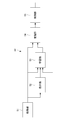
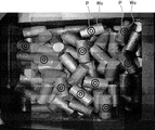
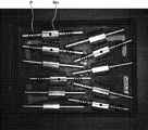
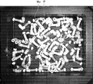
- FIG. 1st Embodiment of this disclosure It is a schematic diagram which shows the structure of the extraction system of 1st Embodiment of this disclosure. It is a block diagram which shows the flow of information in the extraction system of FIG. It is a block diagram which shows the structure of the teaching part of the extraction system of FIG. It is a figure which shows an example of the teaching screen on the 2D camera image in the extraction system of FIG. It is a figure which shows another example of the teaching screen on the 2D camera image in the extraction system of FIG. It is a figure which shows still another example of the teaching screen on the 2D camera image in the extraction system of FIG. It is a block diagram which illustrates the hierarchical structure of the convolutional neural network in the extraction system of FIG.
- FIG. 1 shows the configuration of the take-out system 1 according to the first embodiment.
- the take-out system 1 is a system that takes out work W one by one from the existing area (inside the container C) of a plurality of work W.
- the extraction system 1 includes an information acquisition device 10 for photographing the inside of a container C in which a plurality of work Ws are randomly overlapped and accommodated, a robot 20 for extracting the work W from the container C, and a display device capable of displaying a two-dimensional image.
- a user-capable input device 40, a robot 20, a display device 30, and a control device 50 for controlling the input device 40 are provided.
- the information acquisition device 10 can be a camera that captures a visible light image such as an RGB image or a grayscale image.
- a camera that acquires an invisible light image for example, an infrared camera that acquires a thermal image for inspection of a person or an animal, an ultraviolet camera that acquires an ultraviolet image for inspection of scratches or spots on the surface of an object, a disease diagnosis. It can also be an X-ray camera that acquires an image for seabed, or an ultrasonic camera that acquires an image for seafloor search.
- the information acquisition device 10 is arranged so as to photograph the entire internal space of the container C from above.
- the installation method is not limited to this, and the camera is fixed to the hand of the robot 20 and moves with the movement of the robot while moving from different positions and angles to the container C. It may be arranged so as to photograph the internal space.
- the camera is fixed to the hand of a robot different from the robot 20 that performs the take-out operation to take a picture, and the robot 20 takes out the acquired data and the processing result of the camera by communication between the control devices of the different robots. The operation may be carried out.
- the information acquisition device 10 may have a configuration for measuring the depth of each pixel of the two-dimensional image to be captured (the vertical distance from the information acquisition device 10 to the subject). Examples of the configuration for measuring such depth include a distance sensor such as a laser scanner and a sound wave sensor, a second camera for configuring a stereo camera, a camera moving mechanism, and the like.
- the robot 20 has a take-out hand 21 that holds the work W at the tip.
- the robot 20 can be a vertical articulated robot as illustrated in FIG. 1, but is not limited to this, and may be, for example, a Cartesian coordinate robot, a scalar robot, a parallel link robot, or the like. ..
- the take-out hand 21 can have an arbitrary configuration capable of holding the work Ws one by one.
- the take-out hand 21 can be configured to have a suction pad 211 that sucks the work W.
- the suction hand that sucks the work by utilizing the airtightness of the air may be used, but the suction hand that does not require the airtightness of the air and has a strong suction force may be used.
- the take-out hand 21 may have a pair of gripping fingers 212 or three or more gripping fingers 212 for sandwiching and holding the work W as in the alternative shown by the two-dot chain line in FIG. It may have a configuration (not shown) having a plurality of suction pads 211. Alternatively, it may be configured to have a magnetic hand (not shown) that holds a work made of iron or the like by a magnetic force.
- the display device 30 is a display device capable of displaying a two-dimensional image such as a liquid crystal display or an organic EL display, and displays the image according to an instruction from the control device 50 described later. Further, the display device 30 may be integrated with the control device 50.
- the display device 30 draws and displays a two-dimensional virtual hand P reflecting the two-dimensional shape and size of the take-out hand 21 in contact with the work on the two-dimensional image.
- a circle or ellipse that reflects the shape and size of the tip of the suction pad, a rectangle that reflects the shape and size of the tip of the magnetic hand, etc. are drawn on the two-dimensional image, and the normal arrow shape pointed to by the mouse. Instead of the pointer of, this circular, elliptical, or rectangular two-dimensional virtual hand P is always drawn and displayed.
- the circular, elliptical, or rectangular two-dimensional virtual hand P is moved on the two-dimensional image and placed on the work on the two-dimensional image to be taught by the user.
- the virtual hand P can confirm whether or not there is interference with the work around the work and whether or not the virtual hand P is significantly deviated from the center of the work.
- the two-dimensional virtual hand P reflecting the center position may be drawn and displayed on the two-dimensional image. For example, for a hand having two suction pads, a straight line connecting the centers of two circles or ellipses representing the suction pads is drawn and displayed, and a dot is drawn and displayed at the midpoint of the straight line, or two A straight line connecting the centers of two ellipses representing the gripping finger is drawn and displayed on the gripping hand having the gripping finger, and a dot is drawn and displayed at the midpoint of the straight line.
- a dot representing the take-out center position of the hand is placed near the center of gravity of the work.
- the position of the center of take-out can be taught, and the posture of the two-dimensional virtual hand P can be taught by matching the above-mentioned straight line representing the longitudinal direction of the hand with the axial direction which is the longitudinal direction of the rotation axis.
- the work can be held in a well-balanced manner without being significantly deviated from the center of gravity of the work, and the two suction pads or gripping fingers can both contact the work at two points to stably hold the work, like a directional elongated rotating shaft. Work can be taken out stably.
- the two-dimensional virtual hand reflects the interval of the take-out hand 21 in the portion in contact with the work.
- P may be drawn and displayed on the two-dimensional image. For example, for a hand having two suction pads, a straight line representing the distance between the centers of two circles or ellipses representing the suction pads is drawn and displayed, and the value of the distance between the centers is numerically displayed. A dot may be drawn at the midpoint and displayed as the center position for taking out the hand.
- a straight line representing the distance between the centers of two rectangular rectangles representing the gripping fingers is drawn and displayed, and the value of the distance between the centers is numerically displayed.
- a dot may be drawn at the midpoint and displayed as the center position for taking out the hand.
- a two-dimensional virtual hand that reflects the combination of the two-dimensional shape, size, hand direction (two-dimensional posture), and spacing of the take-out hand 21 in contact with the work. P may be drawn and displayed on a two-dimensional image.
- simple marks such as small dots, circles, and triangles are placed on the two-dimensional image at the teaching position on the two-dimensional image taught by the user by the teaching unit 52 described later. It may be drawn and displayed. By looking at this simple mark, the user can grasp where on the two-dimensional image is taught, where is not taught, and whether the total number of teaching positions is too small. Furthermore, it will be possible to check whether the position already taught is actually off-center of the work, and whether the position that was not intended by mistake was taught (for example, the mouse was mistakenly clicked twice at a close position). ..
- the types of teaching positions are different, for example, when a plurality of types of workpieces are mixed, different marks are drawn and displayed at the teaching positions on the different workpieces, and dots are drawn at the teaching positions on the cylindrical workpiece. You may draw a triangle at the teaching position on the cube work and teach it so that it can be distinguished.
- the display device 30 may display the two-dimensional virtual hand P on the two-dimensional image and numerically display the value of the depth of the pixel on the two-dimensional image pointed to by the two-dimensional virtual hand P. Further, the two-dimensional virtual hand P may be displayed on the two-dimensional image, and the size of the two-dimensional virtual hand P may be changed and displayed according to the depth information for each pixel on the two-dimensional image. Alternatively, both may be displayed. Even for the same work, the deeper the depth from the shooting position of the camera, the smaller the size of the work shown on the image.
- the size of the 2D virtual hand P is reduced according to the depth information, and the proportionality between the size of each work shown on the image and the size of the 2D virtual hand P is set to the actual size of the work in the real world and the take-out hand 21.
- the user can accurately grasp the situation in the real world and give correct teaching.
- the input device 40 can be a device such as a mouse, a keyboard, a touch pad, or the like on which a user can input information.
- the user can turn the mouse wheel or press a key on the keyboard to display the two-dimensional image by finger operation on the touchpad (for example, pinch-in / pinch-out of finger operation on the smartphone).
- the touchpad for example, pinch-in / pinch-out of finger operation on the smartphone.
- the user can click and hold the right mouse button and move the mouse, or press a key on the keyboard (eg, arrow keys) to operate the finger on the touchpad (eg, finger operation on the smartphone). ), Move the displayed two-dimensional image and check the area of interest of the user. Click the left mouse button, keyboard keys, touchpad, etc. to teach the user the position you want to teach.
- a key on the keyboard eg, arrow keys
- the finger on the touchpad eg, finger operation on the smartphone.
- the input device 40 is a device such as a microphone, whereby the user inputs a voice command, and the control device 50 receives the voice command, performs voice recognition, and automatically teaches according to the content thereof. It may be said that. For example, upon receiving a voice command "center of white plane” from the user, the control device 50 recognizes three keywords such as “white”, “plane”, and “center”, and is “white” and “flat”. The feature such as “” may be estimated by image processing, and the teaching may be automatically performed using the "center” position of the estimated “white plane” as the teaching position.
- the input device 40 may be a device such as a touch panel integrated with the display device 30. Further, the input device 40 may be integrated with the control device 50. In this case, the user teaches using the touch panel or keyboard of the teaching operation panel of the control device 50.
- FIG. 2 shows the flow of information between each component of the control device 50.
- the control device 50 can be realized by having one or a plurality of computer devices including a CPU, a memory, a communication interface, and the like execute an appropriate program.
- the control device 50 includes an acquisition unit 51, a teaching unit 52, a learning unit 53, an inference unit 54, and a control unit 55. These components are functionally distinct and do not need to be clearly distinguishable in physical and program structures.
- the acquisition unit 51 acquires 2.5-dimensional image data (data including depth information for each pixel of the two-dimensional camera image and the two-dimensional camera image) of the existing region of the plurality of work Ws.
- the acquisition unit 51 may receive the two-dimensional camera image and the 2.5-dimensional image data including the depth information from the information acquisition device 10, and the two-dimensional camera image data from the information acquisition device 10 having no depth information measurement function.
- the depth of each pixel may be estimated and 2.5-dimensional image data may be generated by receiving only the data and analyzing the two-dimensional camera image data.
- the 2.5-dimensional image data may be described as image data below.
- the acquisition unit 51 acquires a plurality of images of the same arrangement inside the same container C from different distances (distance information is known) without changing the arrangement of the workpieces inside the container C. Based on the data obtained, the depth (distance from the camera) of the pixel in which the work W exists can be calculated based on the size of the work W or its characteristic portion on the newly captured two-dimensional camera image.
- one camera is fixed to the camera movement mechanism or the hand of the robot, and two-dimensional based on the positional deviation (misparity) of the feature points of a plurality of two-dimensional camera images with different viewpoints taken from different distances and angles.
- the depth of the feature points on the camera image may be estimated.
- Deep learning may be used to estimate the depth from the size of the work actually shown on the image.
- the teaching unit 52 displays the two-dimensional camera image acquired by the acquisition unit 51 on the display device 30, and the target work Wo to be taken out from the plurality of work Ws on the two-dimensional camera image by the user using the input device 40. It is configured to be able to teach a two-dimensional extraction position or an extraction position with depth information.
- the teaching unit 52 selects 2.5-dimensional image data or a two-dimensional camera image from which the user performs a teaching operation via the input device 40 from the data acquired by the acquisition unit 51.
- a teaching interface 522 that manages the exchange of information between the selection unit 521, the display device 30 and the input device 40, and a teaching data processing unit that processes the information input by the user and generates teaching data that can be used by the learning unit 53.
- the configuration may include a 523 and a teaching data recording unit 524 that records the teaching data generated by the teaching data processing unit 523.
- the teaching data recording unit 524 is not an essential configuration of the teaching unit 52. For example, it may be stored using a storage unit such as an external computer, storage, or server.
- FIG. 4 shows an example of a two-dimensional camera image displayed on the display device 30.
- FIG. 4 is a photograph of the container C in which the columnar work W is randomly housed.
- the two-dimensional camera image is easy to acquire (the acquisition device is inexpensive), and unlike the distance image, data omission (pixels whose values cannot be specified) is unlikely to occur. Further, the two-dimensional camera image is similar to the image when the user directly looks at the work W. Therefore, when the teaching unit 52 causes the user to input the teaching position on the two-dimensional camera image, the target work Wo can be taught by fully utilizing the knowledge of the user.
- the teaching unit 52 may be configured so that a plurality of teaching positions can be input on one two-dimensional camera image. As a result, it is possible to efficiently teach and make the extraction system 1 learn the appropriate extraction of the work W in a short time. Further, when the above-mentioned plurality of types of works are mixed, different marks may be drawn on the different types of works, and the works may be classified and displayed according to the nature of the plurality of teaching positions taught. As a result, the user can visually grasp the type of work for which the number of teachings is insufficient, and it is possible to prevent insufficient learning due to the insufficient number of teachings.
- the teaching unit 52 may display a two-dimensional camera image captured in real time. Further, the teaching unit 52 may read out and display a two-dimensional camera image captured in the past and stored in the memory device. The teaching unit 52 may be configured so that the user can input the teaching position on the two-dimensional camera image taken in the past. A plurality of two-dimensional camera images taken in advance may be registered in the database. The teaching unit 52 can select the two-dimensional camera image used for teaching from the database, and can further register the teaching data recording the teaching position to be taught in the database. By registering the teaching data in the database, the teaching data can be shared among a plurality of robots installed in different places in the world, and the teaching can be performed more efficiently.
- the user sets the work W that should be taken out first as the target work Wo, and teaches the take-out reference position of the take-out hand 21 that can hold the target work Wo as the teaching position.
- the user targets a work W having a high degree of exposure, for example, a work W in which another work W does not overlap, or a work W having a shallow depth (located above the other work W). It is preferable to use work Wo.
- the take-out hand 21 has the suction pad 211, the user preferably sets the work W in which the portion having a larger flat surface appears in the two-dimensional camera image as the target work Wo.
- the suction pad 211 can easily and reliably suck and take out the work while maintaining airtightness.
- the take-out hand 21 sandwiches the work W by a pair of gripping fingers 212
- the user targets a work in which no other work W or obstacles exist in the spaces on both sides where the gripping fingers 212 of the take-out hand 21 should be arranged. It is preferable to use work Wo.
- the work W is gripped at the interval of the pair of gripping fingers 212 displayed on the image, the user sets the work in which the contact portion having a wider contact area between the gripping fingers and the work is exposed as the target work Wo. It is preferable to do so.
- the teaching unit 52 may be configured to teach the teaching position using the virtual hand P described above. As a result, the user can easily recognize an appropriate teaching position in which the target work Wo can be taken out and held by the hand 21.
- the virtual hand P has a concentric shape that imitates the outer shell of the suction pad 211 and the air flow path for suction at the center of the suction pad 211. May be good.
- the take-out hand 21 has a plurality of suction pads 211, as shown in FIG. 5, the virtual hand P has an outer shell of each suction pad 211 and an air flow path for suction at the center of each suction pad 211. It can be multiple imitations.
- the take-out hand 21 has a pair of gripping fingers 212
- the virtual hand P can have a pair of rectangles indicating the outer shell of the gripping fingers 212, as shown in FIG.
- the virtual hand P may be displayed by reflecting the characteristics of the take-out hand 21 so that the take-out hand P can be taken out successfully.
- the suction pad 211 which is a portion in contact with the work can be displayed as two concentric circles (see FIG. 4) on the two-dimensional image.
- the inner circle represents the air passage, so that the user does not have holes, steps, grooves, etc. in the area where the inner circle and the work overlap, so that the airtightness is not lacking in the successful removal.
- the outer circle represents the outermost boundary line of the suction pad 211, and the position where the outer circle does not interfere with the surrounding environment (adjacent work, container wall, etc.) is taught as the teaching position. Then, the take-out hand 21 can take out the work without interfering with the surrounding environment during the take-out operation. Further, if the size of the concentric circles is changed and displayed according to the depth information for each pixel on the two-dimensional image, more accurate teaching can be performed according to the actual proportion between the work in the real world and the suction pad 211.
- the teaching unit 52 may be configured to teach the two-dimensional take-out posture (two-dimensional posture) of the take-out hand 21. As shown in FIGS. 5 and 6, when the take-out hand 21 has a plurality of suction pads 211 or has a pair of gripping fingers 212, and the portion of the take-out hand 21 in contact with the target work Wo has directionality. Is preferably able to teach the two-dimensional angle of the displayed virtual hand P (two-dimensional take-out posture of the take-out hand 21). In order to adjust the two-dimensional angle of the virtual hand P in this way, the virtual hand P may have a handle for adjusting the angle, or an arrow indicating the direction of the take-out hand 21 (for example, the center).
- the angle (two-dimensional posture) formed by such a handle or arrow with the longitudinal direction of the target work Wo may be displayed in real time for teaching.
- the input device 40 for example, by moving the mouse while pressing the right button of the mouse, the handle or the arrow is rotated, and the longitudinal direction of the take-out hand 21 coincides with the longitudinal direction of the target work Wo.
- the left mouse button may be clicked to teach the angle.
- the take-out hand 21 is aligned with the orientation of the work W. While maintaining the airtightness required for air adsorption, the work can be held and taken out in a well-balanced state, and the work W can be taken out reliably.
- a take-out hand 21 having two suction pads 211 is used to suck and take out the work W, which is a long iron rotating shaft having one groove in the thick portion in the middle.
- the work W which is a long iron rotating shaft having one groove in the thick portion in the middle.
- the two suction pads 211 are brought into contact with each other at positions of about 1/3 and 2/3 in the longitudinal direction of the work W, so that the work W is balanced when it is lifted.
- the work W can be reliably held and taken out without breaking and falling.
- the center position of the two suction pads 211 (the midpoint of the straight line connecting the two suction pads 211, for example, drawn and displayed as a dot) is the center of the thick part in the middle of the rotation axis.
- the center position of the take-out is taught by arranging according to the above, and the longitudinal direction of the take-out hand 21 (the direction along the straight line connecting the two suction pads 211) is the rotation axis by using the displayed handle or arrow.
- the two-dimensional take-out posture of the take-out hand 21 may be taught so as to coincide with the longitudinal direction of the work W.
- the work W is an air joint provided with a pipe screw at one end, a tube connecting coupler bent at 90 ° at the other end, and a polygonal columnar nut portion in which a tool engages at the center portion.
- the take-out hand 21 having a pair of gripping fingers 212.
- the take-out hand 21 takes out the hand 21 so as to sandwich the polygonal columnar nut portion having the largest flat surface in the work W by a pair of gripping fingers 212 whose sandwiching side is a flat surface. Teach the take-out center position of.
- the two-dimensional angle is taught so that the normal direction of the plane of the contacting nut portion and the opening / closing direction of the pair of gripping fingers 212 coincide with each other.
- the work W can be reliably held with a stronger gripping force by obtaining a larger plane contact and generating a larger frictional force without causing an extra two-dimensional rotational movement of the work Wo.
- the user can use the two-dimensional shape and size of the pair of gripping fingers 212 and the plurality of suction pads 211, the directionality (for example, the longitudinal direction, the opening / closing direction) and the center position of the hand, and the plurality of pads.
- the virtual hand P reflecting the distance between the fingers and the fingers can be positioned at a position where the actual suction pad 211 and the gripping finger 212 should be arranged with respect to the target work Wo, and the teaching position can be taught.
- the teaching unit 52 may be configured to teach the order of taking out a plurality of target works Wo.
- the order in which the depth information included in the 2.5-dimensional image data acquired by the information acquisition device 10 is displayed on the display device 30 and taken out may be taught. For example, by acquiring the depth information corresponding to each pixel on the 2D camera image pointed to by the virtual hand P from the 2.5D image data and displaying the depth value in real time, a plurality of close values are obtained. It is possible to determine which work position is on the top and which work position is on the bottom in the work.
- the user can teach the order of taking out the work located above so as to preferentially take out the work located above by moving the virtual hand P to each pixel position, checking the value of the depth, and comparing numerically. become.
- the user may visually check the two-dimensional camera image and teach the extraction order so that the work W having a high degree of exposure is preferentially extracted without being covered by the surroundings, and the displayed depth value is smaller (The take-out order may be taught so as to preferentially take out the work W (located higher) and having a higher degree of exposure.
- the teaching unit 52 may be configured so that the user can teach the operating parameters of the take-out hand 21. For example, when the take-out hand 21 has two or more contact positions with the target work Wo, the teaching unit 52 may be configured to teach the opening / closing degree of the take-out hand 21. As the operation parameter of the take-out hand 21, the distance between the pair of gripping fingers 212 (the degree of opening / closing of the take-out hand 21) when the take-out hand 21 has the pair of gripping fingers 212 can be mentioned.
- both sides of the target work Wo are set. Since the space for inserting the required gripping finger 212 can be reduced, the work W that can be taken out by the take-out hand 21 can be increased. Further, when there are a plurality of regions on the work W where the work W can be stably gripped, it is preferable to teach different degrees of opening and closing according to the width of each grippable region.
- the work W that can be taken out can be increased by the taking-out hand 21.
- the depth information of the center position of the candidate region is used to preferentially determine the topmost candidate region as the gripping target. It can be taken out with a reduced risk of failure due to being covered by the work.
- the teaching unit 52 may be configured to teach the gripping force by the gripping finger. Further, when the teaching unit 52 does not have a sensor for detecting the gripping force of the gripping finger, the teaching unit 52 teaches the opening / closing degree of the take-out hand 21 and grips the hand based on the correspondence between the opening / closing degree and the gripping force estimated in advance. The force may be estimated and taught.
- the opening / closing degree (finger spacing) of the pair of gripping fingers 212 at the time of gripping is displayed on the display device 30, the opening / closing degree of the gripping fingers 212 displayed via the input device 40 is adjusted, and the target work Wo is gripped.
- the adjusted opening / closing degree (that is, the distance between the gripping fingers 212 at the time of gripping) becomes an index that visualizes the strength of the gripping force at which the take-out hand 21 grips the target work Wo. You can also do it. Specifically, the smaller the theoretical distance between the pair of gripping fingers 212 during gripping is smaller than the width of the gripped portion on the work, the stronger the take-out hand 21 is so that the work W is deformed after coming into contact with the work W. Since it is gripped, the gripping force of the take-out hand 21 is increased.
- overlap amount the difference between the theoretical distance between the gripping fingers 212 and the normal width of the gripped portion of the work W (hereinafter referred to as "overlap amount") is the elastic deformation of the gripping fingers 212 and the work W.
- the elastic force of this elastic deformation acts as a gripping force on the target work Wo.
- the gripping finger 212 and the work W are not in contact with each other or are in light point contact so that the force is not transmitted. It will be. Since the user can visually confirm such a situation by visually checking the displayed value of the gripping force, it is possible to prevent the work W from falling due to insufficient gripping force.
- the teaching unit 52 may be configured to teach gripping stability.
- the teaching unit 52 analyzes the frictional force acting during the contact between the gripping finger 212 and the target work Wo using the Coulomb friction model, and is an index showing the gripping stability defined based on the Coulomb friction model.
- the analysis result is graphically and numerically displayed on the display device 30. The user can adjust the take-out position and the two-dimensional take-out posture of the take-out hand 21 while visually confirming the result, and can teach to obtain higher gripping stability.
- the method of teaching the gripping stability on the two-dimensional camera image by the teaching unit 52 is the same as the method of teaching the gripping stability on the three-dimensional point cloud data described by the second embodiment described later. Since there are quite a lot of parts, here we will omit duplicate descriptions and describe only the differences.
- the Coulomb friction model shown in FIG. 13 is described three-dimensionally, and in that case, the desirable contact force that does not cause slippage between the gripping finger 212 and the target work Wo is the three-dimensional conical space shown in the figure. It is inside.
- the desirable contact force that does not cause slippage between the gripping finger 212 and the target work Wo is an image plane that is a two-dimensional plane in the above-mentioned three-dimensional conical space. It can be represented as being in a two-dimensional triangular area obtained by projecting onto.
- the candidate group of the desirable contact force f that does not cause slippage between the gripping finger 212 and the target work Wo is the Coulomb friction coefficient.
- ⁇ and positive pressure f ⁇ it is a two-dimensional triangular two-dimensional space (force triangular space) Af in which the maximum value of the apex angle does not exceed 2 tan -1 ⁇ .
- the contact force for stably gripping the target work Wo without causing slippage needs to exist inside this force triangular space Af.
- Afi 1, 2, ... Is the total number of contact positions.
- Ami 1, 2, ... Is the total number of contact positions.
- the volumes of the above-mentioned minimum convex hulls Hf and Hm are set as the areas of two different two-dimensional convex spaces, respectively. You can ask. The larger the area, the easier it is to include the center of gravity G of the target work Wo, and the more candidates for the force and moment for stable gripping, so that it can be judged that the gripping stability is high.
- ⁇ is the shortest distance from the center of gravity G of the target work Wo to the boundary of the minimum convex hull Hf or Hm (the shortest distance to the boundary of the minimum convex hull Hf of force ⁇ f or the boundary of the minimum convex hull Hm of the moment.
- the Qo defined in this way can be used regardless of the number of gripping fingers 212 (the number of contact positions).
- the index indicating the gripping stability is at least one of the plurality of contact positions of the virtual hand P with respect to the target work Wo and the friction coefficient between the take-out hand 21 and the target work Wo at each contact position. It is defined using at least one of the volume of the minimum convex hull Hf and Hm calculated by using one and the shortest distance from the center of gravity G of the target work Wo to the boundary of the minimum convex hull.
- the teaching unit 52 numerically displays the calculation result of the gripping stability evaluation value Qo on the display device 30 when the user temporarily inputs the take-out position and the posture of the take-out hand 21.
- the user can confirm whether the gripping stability evaluation value Qo is appropriate in comparison with the threshold value displayed at the same time. It may be configured so that it is possible to select whether to determine the input take-out position and the posture of the take-out hand 21 as teaching data, or to correct the take-out position and the posture of the take-out hand 21 and re-input.
- the teaching unit 52 graphically displays the volume V of the minimum convex hulls Hf and Hm and the shortest distance ⁇ from the center of gravity G of the target work Wo on the display device 30, thereby optimizing the teaching data so as to satisfy the threshold value. It may be configured to be intuitively easy to convert.
- the teaching unit 52 displays the two-dimensional camera images of the work W and the container C, displays the take-out position and the take-out posture taught by the user, and plots the minimum convex hull Hf and Hm, the volume and the shortest distance calculated thereby. It may be configured to display numerically numerically, present the volume for stable gripping and the threshold value of the shortest distance, and display the judgment result of gripping stability. As a result, the user can visually confirm whether or not the center of gravity G of the target work Wo is inside Hf and Hm.
- the user When the user finds that the center of gravity G is off, the user changes the teaching position and teaching posture and clicks the recalculation button, and the minimum convex hulls Hf and Hm reflecting the new teaching position and teaching posture are graphically It will be updated and reflected.
- the user can teach the desired position and posture such that the center of gravity G of the target work Wo is inside Hf and Hm while visually confirming. While confirming the judgment result of the gripping stability, the user can change the teaching position and the teaching posture as necessary to teach so as to obtain higher gripping stability.
- the teaching unit 52 may be configured to teach the take-out position of the work W based on the CAD model information of the work W. For example, the teaching unit 52 acquires features such as holes, grooves, and planes of the work W appearing on the two-dimensional image from image preprocessing, finds the same features on the three-dimensional CAD model of the work W, and obtains the same features.
- a 2D CAD diagram generated by projecting a 3D CAD model onto the feature plane of the work (the plane of holes and grooves on the work, or the plane itself on the work) as the center is near the same feature on the 2D image.
- the two-dimensional CAD diagram is arranged so as to match the image and match the neighboring image.
- the teaching unit 52 may be configured to teach the two-dimensional take-out posture of the work W based on the CAD model information of the work W. For example, using the method of matching with the CAD data of the work W described above, a mistake in teaching the two-dimensional extraction posture of the symmetric work is made based on the two-dimensional CAD diagram arranged so as to match the two-dimensional image. It is possible to eliminate the teaching error caused by the presence of blur in a part of the area of the two-dimensional image.
- the learning unit 53 uses the two-dimensional camera image as input data for the target work by machine learning (supervised learning) based on the learning input data in which the teaching data including the two-dimensional extraction position which is the teaching position is added to the two-dimensional camera image. Generate a learning model that infers the two-dimensional extraction position of Wo. Specifically, the learning unit 53 digitizes the commonality between the camera image in the vicinity region of each pixel and the camera image in the vicinity region of the teaching position in the two-dimensional camera image by a convolutional neural network (Convolutional Neural Network). A learning model to be determined is generated, a higher score is given to a pixel having a higher commonality with the teaching position, the evaluation is higher, and the taking-out hand 21 infers as a target position to be picked up with higher priority.
- Convolutional Neural Network convolutional Neural Network
- the learning unit 53 adds teaching data including the extraction position with depth information, which is the teaching position, to the 2.5-dimensional image data (data including the depth information for each pixel of the two-dimensional camera image and the two-dimensional camera image).
- teaching data including the extraction position with depth information, which is the teaching position
- 2.5-dimensional image data data including the depth information for each pixel of the two-dimensional camera image and the two-dimensional camera image.
- machine learning supervised learning
- a learning model that infers the extraction position of the target work Wo with depth information using 2.5-dimensional image data as input data may be generated. ..
- the learning unit 53 quantifies the commonality between the camera image in the vicinity of each pixel and the camera image in the vicinity of the teaching position in the two-dimensional camera image by a convolutional neural network (Convolutional Neural Network).
- Convolutional Neural Network Convolutional Neural Network
- the judgment rule A is established, and the depth image of the vicinity region of each pixel and the depth of the vicinity region of the teaching position in the depth image converted from the depth information of each pixel by another convolutional neural network (Convolutional Neural Network) are established.
- Rule B is established to quantify the commonality with the image, and the commonality between rule A and the teaching position comprehensively judged by rule B is higher.
- the extraction position with depth information is given a higher score. It may be highly evaluated and inferred as the target position where the take-out hand 21 should go for pick-up with higher priority.
- the teaching unit 52 further teaches the two-dimensional angle of the virtual hand P indicating the taking-out hand 21 (the two-dimensional taking-out posture of the taking-out hand 21)
- the learning unit 53 further teaches the two-dimensionality of the taught virtual hand P.
- a learning model that infers the two-dimensional angle (two-dimensional take-out posture) of the take-out hand 21 when taking out the target work Wo is generated.
- the learning unit 53 connects the teaching position (the two-dimensional extraction center position of the extraction hand 21, for example, the center position of the straight line connecting the two suction pads 211, or the fingers of the pair of gripping fingers 212) to the two-dimensional camera image.
- a learning model that infers the posture may be generated.
- the two-dimensional take-out center position taught is set as the center position, and the unit length from the center position (for example, two suction pads 211 or a pair of gripping fingers) is determined by the two-dimensional take-out teaching posture at this position.
- the two-dimensional positions separated by (a value of 1/2 of the interval of 212) are calculated, and the calculated two-dimensional position is set as the second teaching position.
- the problem of inferring the two-dimensional extraction center position and the second two-dimensional position in the vicinity that is separated from that position by a unit length based on the two-dimensional camera image. Can be equivalently converted to.
- a learning model that infers the two-dimensional extraction center position based on the two-dimensional camera image can be generated by the same method as described above.
- the teaching position is set in the image of the square area near the teaching position where the length of one side is four times the unit length centered on the teaching position.
- One of the second two-dimensional positions may be inferred from a plurality of two-dimensional position candidates distributed at 360 degrees on a circle whose center is a unit length as a radius. Based on the image of this square area, the relationship between the teaching position at the center and the second teaching position is learned by another convolutional neural network (Convolutional Neural Network) to generate a learning model.
- Convolutional Neural Network another convolutional neural network
- the learning unit 53 sets the teaching position (the extraction position with the depth information) and the teaching posture (the extraction hand) in the 2.5-dimensional image data (data including the depth information for each pixel of the two-dimensional camera image and the two-dimensional camera image).
- a learning model for inferring the extraction position with depth information and the two-dimensional extraction posture based on 2.5-dimensional image data is generated. May be good. Specifically, it may be carried out by a combination of the above-mentioned methods.
- the structure of the convolutional neural network of the learning unit 53 is as follows: Function2D (2D convolutional calculation), AvePooling2D (2D averaging pooling calculation), UnPolling2D (2D pooling inverse calculation), Batch Normalization (data data). It can include multiple layers such as a function that maintains normality) and a ReLU (activation function that prevents the vanishing gradient problem).
- Function2D 2D convolutional calculation
- AvePooling2D 2D averaging pooling calculation
- UnPolling2D (2D pooling inverse calculation
- Batch Normalization data data
- It can include multiple layers such as a function that maintains normality) and a ReLU (activation function that prevents the vanishing gradient problem).
- the dimension of the input 2D camera image is reduced, the necessary feature map is extracted, and the dimension of the original input image is returned to predict the evaluation score for each pixel on the input image. And output the predicted value in full size.
- the weighting coefficient of each layer is updated and determined by learning so that the difference between the output prediction data and the teaching data gradually becomes smaller.
- the learning unit 53 searches all the pixels on the input image as candidates evenly, calculates all the predicted scores at once in full size, and has a high degree of commonality with the teaching position from among them, and takes out the hand. It is possible to generate a learning model that obtains a candidate position that is likely to be extracted by 21. By inputting the image in full size and outputting the predicted scores of all the pixels on the image in full size in this way, the optimum candidate position can be found without omission.
- the depth and complexity of the layers of the specific convolutional neural network may be adjusted according to the size of the input two-dimensional camera image, the complexity of the work shape, and the like.
- the learning unit 53 is configured to determine the quality of the learning result by machine learning based on the above-mentioned learning input data and display the determination result on the teaching unit 52, and the determination result is NG. Further may be configured to display a plurality of learning parameters and adjustment hints on the teaching unit 52 so that the user can adjust the learning parameters and perform re-learning. For example, a transition map or a distribution map of the learning accuracy with respect to the learning input data and the test data is displayed, and if the learning accuracy does not increase even if the learning progresses, or if it is lower than the threshold value, it can be determined as NG. In addition, it seems that the user does not teach whether the correct answer rate, recall rate, precision rate, etc.
- the adjustment hint is also displayed on the teaching unit 52 and presented to the user so that a high accuracy rate, a recall rate, and a precision rate can be obtained.
- the user can adjust the learning parameters and perform re-learning based on the adjustment hints presented. In this way, by presenting the judgment result and the adjustment hint of the learning result by the learning unit 53 to the user without performing the actual extraction experiment, it is possible to generate a highly reliable learning model in a short time. become.
- the learning unit 53 feeds back not only the teaching position taught by the teaching unit 52 but also the inference result of the extraction position inferred by the inference unit 54 described later to the above-mentioned learning input data, and is based on the changed learning input data.
- the above-mentioned learning input data is modified so that the extraction position having a low evaluation score in the inference result by the inference unit 54 is excluded from the teaching data, and machine learning is performed again based on the modified learning input data to perform a learning model. May be adjusted.
- the inference unit 54 analyzes the characteristics of the extraction position having a high evaluation score in the inference result, and although it is not taught by the user on the two-dimensional camera image, it has a commonality with the extraction position having a high inferred evaluation score.
- a pixel with a high value may be automatically given a label by internal processing as a teaching position. As a result, it is possible to correct the misjudgment of the user and generate a learning model with higher accuracy.
- the learning unit 53 inputs the result of inference including the two-dimensional extraction posture inferred by the reasoning unit 54, which will be described later, into the above-mentioned learning input.
- the above-mentioned learning input data is modified so as to exclude the two-dimensional extraction posture having a low evaluation score in the inference result by the inference unit 54 from the teaching data, and machine learning is performed again based on the modified learning input data. You may go and adjust the learning model.
- the inference unit 54 performs feature analysis such as a two-dimensional extraction posture having a high evaluation score in the inference result, and a two-dimensional image having a high inferred evaluation score although not taught by the user on the two-dimensional camera image. Labels may be automatically added by internal processing so as to add to the teaching data what has a high degree of commonality with the taking-out posture of the data.
- the learning unit 53 uses the control result of the extraction operation of the robot 20 by the control unit 55 based on not only the teaching position taught by the teaching unit 52 but also the extraction position inferred by the inference unit 54 described later, that is, the robot 20.
- the result information of the success or failure of the extraction operation of the target work Wo may be added to the learning input data and machine learning may be performed to generate a learning model for inferring the extraction position of the target work Wo. From this, even if the plurality of teaching positions taught by the user include more incorrect teaching positions, the user's judgment error is corrected by performing re-learning based on the result of the actual retrieval operation. It is possible to generate a learning model with even higher accuracy. In addition, with this function, it is possible to generate a learning model by automatic learning without prior instruction by the user by utilizing the success / failure result of the operation of picking up at a randomly determined take-out position.
- the learning unit 53 extracts the target work Wo by the control unit 55 using the robot 20 based on the extraction position inferred by the inference unit 54 described later, the work is left behind in the container C.
- the situation may also be configured to learn and adjust the learning model.
- the image data when the work W is left behind in the container C is displayed on the teaching unit 52, and the user can additionally teach the take-out position and the like.
- One such leftover image may be taught, but a plurality of such leftover images may be displayed.
- the data additionally taught in this way is also included in the learning input data, and learning is performed again to generate a learning model.
- a state in which the number of works in the container C decreases with the taking-out operation and it becomes difficult to take out for example, a state in which works close to the wall side or the corner side of the container C are left behind is likely to appear.
- the overlapping state it is difficult to take out in that posture, for example, when the work posture or the work overlaps so that all the positions corresponding to the teaching positions are hidden behind the camera and are not captured by the camera. Or, although it is reflected in the camera, it may interfere with the hand and the container C or other work if it is taken out because it is quite slanted. There is a high possibility that the trained model cannot handle the overlapping state and work state of these leftovers.
- the user additionally teaches another position on the side far from the wall or the corner, another position that is not hidden and is reflected in the camera, or another position that is not so slanted, and the additionally taught data. This problem can be solved by putting in and learning again.
- the learning unit 53 is a control unit based on the inference result including the two-dimensional extraction posture inferred by the inference unit 54 described later.
- Machine learning is performed based on the control result of the extraction operation of the robot 20 by 55, that is, the result information of the success or failure of the extraction operation of the target work Wo performed using the robot 20, and the two-dimensional extraction posture of the target work Wo is also obtained. Further, a learning model to be inferred may be generated.
- the success / failure result of taking out the target work Wo may be determined by the detection value of the sensor mounted on the take-out hand 21, and the result of taking out the target work Wo may be determined by the detection value of the sensor mounted on the take-out hand 21. The determination may be made based on the change in the presence or absence of a work in the contact portion.
- the success / failure result of taking out the target work Wo is determined by detecting the change in the vacuum pressure inside the take-out hand 21 with the pressure sensor. May be good.
- the take-out hand 21 having the gripping finger 212 In the case of the take-out hand 21 having the gripping finger 212, the presence or absence of contact between the finger and the target work Wo or the change in the contact force / gripping force is detected by the contact sensor, the tactile sensor, and the force sensor mounted on the finger. The success / failure result of taking out the target work Wo may be determined.
- the value of the opening / closing width of each hand in the state where the work is not gripped and the state in which the work is gripped, or the maximum value and the minimum value of the opening / closing width of the hand are registered, and the opening / closing of the hand is opened / closed.
- the success / failure result of taking out the target work Wo may be determined.
- the success or failure result of taking out the target work Wo by detecting the change in the position of the magnet mounted inside the hand from the position sensor. May be determined.
- the reasoning unit 54 is better, based on the two-dimensional camera image acquired by the acquisition unit 51 and the learning model generated by the learning unit 53, so that the extraction is likely to be successful based on the two-dimensional camera image. At least infer the extraction position.
- the two-dimensional angle of the take-out hand 21 two-dimensional take-out posture
- the two-dimensional angle of the take-out hand 21 two-dimensional take-out posture
- the inference unit 54 when the acquisition unit 51 acquires the 2.5-dimensional image data including the depth information in addition to the two-dimensional camera image, the inference unit 54 generates the acquired 2.5-dimensional image data and the learning unit 53. Based on the training model and based on the 2.5D image data, at least infer the retrieval position with better depth information such that the retrieval is likely to be successful.
- the two-dimensional angle of the take-out hand 21 two-dimensional take-out posture
- the two-dimensional angle of the take-out hand 21 when taking out the target work Wo based on the learning model. Also infer.
- the extraction priority may be set at the plurality of extraction positions.
- the inference unit 54 assigns a high evaluation score to an image having a high degree of commonality with the image in the vicinity of the teaching position from among the images in the vicinity of the plurality of extraction positions, and determines that the image should be extracted first. May be good.
- features such as grooves, holes, steps, dents, and screws that cause the airtightness to be lost in the contact area with the suction pad are included because the work W that overlaps the target work Wo is small and the degree of exposure is high. Success determined by the instructor's knowledge that it is a target work Wo that is easy to take out with few failures because it is a position that is not in place or has a large flat surface that makes it easy for air suction and magnetic suction to succeed. This is because it is inferred as a high-probability extraction position.
- the reasoning unit 54 infers a plurality of extraction positions having commonality with the image in the vicinity of the teaching position, and scores (scores) the commonality of the images to quantitatively determine the priority of extraction.
- a score for example, 90.337,85.991,85.936, which is an evaluation score according to a priority (for example, 1, 2, 3, 4, ).
- On a marker (dot) indicating a take-out position. 84.284) is added.
- the inference unit 54 may set a priority of extraction to a plurality of target work Wo based on the depth information included in the 2.5-dimensional image data acquired by the acquisition unit 51. Specifically, the inference unit 54 may determine that the shallower the depth of the extraction position is, the easier it is to extract the target work Wo, and the higher the priority of extraction. Further, the inference unit 54 is calculated by adding a weighting coefficient by using both the score set according to the depth of the extraction position and the score set according to the commonality of the images in the vicinity of the extraction position. The priority of taking out a plurality of target work Wo may be determined based on the score.
- a threshold value of the score set according to the commonality of the images in the vicinity of the extraction position is set, and all the scores exceeding the threshold value are the extraction positions with a high possibility of success judged by the knowledge of the teacher. Therefore, these may be used as a better candidate group, and those having a shallow extraction position may be preferentially extracted from them.
- the control unit 55 controls the robot 20 to take out the target work Wo by the take-out hand 21 based on the take-out position of the target work Wo.
- the control unit 55 is arranged in one layer based on the extraction position of the work inferred by the inference unit 54, for example, so that there is no overlapping work on the work.
- the image plane of the 2D camera image and the planes of the workpieces lined up in one layer in the real space are calibrated using a calibration jig, etc., and each pixel on the image plane is supported.
- the robot 20 is controlled so as to calculate the position on the plane of the work in the real space and go to pick it up.
- the control unit 55 adds the depth information to the two-dimensional extraction position inferred by the inference unit 54, or the extraction hand at the extraction position with the depth information inferred by the inference unit 54.
- the operation of the robot 20 required for the 21 to go to pick up is calculated, and an operation command is input to the robot 20.
- the control unit 55 analyzes the three-dimensional shape of the target work Wo and its surrounding environment, tilts the extraction hand 21 with respect to the image plane of the two-dimensional camera image, and tilts the two-dimensional camera. By tilting the take-out hand 21 in a direction in which the take-out hand 21 is tilted with respect to the image plane of the image, interference between the work W around the target work Wo and the take-out hand 21 may be prevented.
- the take-out hand 21 is tilted with respect to the image plane and sucked.
- the suction surface of the pad 211 face the contact surface of the target work Wo
- the suction of the target work Wo becomes more reliable.
- the take-out hand 21 is tilted with respect to the tilted target work Wo. The posture of 21 can be corrected.
- pixels and depth information in the vicinity of that position on the image are used.
- One three-dimensional plane may be estimated, the tilt angle of the estimated three-dimensional plane and the image plane may be calculated, and the extraction posture may be corrected three-dimensionally.
- the take-out hand 21 is arranged on the end face side of the target work Wo and the target work Wo is held. May be taken out.
- the user may set a target position at the center of the end face of the target work Wo in the two-dimensional camera image and teach it.
- the longitudinal axis of the target work Wo is inclined with respect to the normal direction of the image plane, it is desirable to incline the take-out hand 21 according to the posture of the target work Wo to take out the work.
- the control unit 55 controls the robot 20 so that the take-out hand 21 approaches and moves along the longitudinal axis direction of the target work Wo.
- a method of determining a desirable approach direction of such an extraction hand 21 one 3 is used for a desirable candidate position on the target work Wo inferred by the inference unit 54 by using pixels and depth information in the vicinity thereof on the image.
- the robot 20 is set so that the take-out hand 21 approaches the target work Wo along the normal direction of the three-dimensional plane that estimates the dimensional plane and reflects the inclination of the take-out surface of the work near the take-out target position. You just have to control it.
- the teaching unit 52 is configured to draw and display simple marks such as small dots, circles, and triangles at the take-out position taught by the user without displaying the above-mentioned two-dimensional virtual hand P for teaching. May be good. Even if the 2D virtual hand P is not displayed, the user sees this simple mark and sees where on the 2D image he has taught, where he has not taught, and whether the total number of teaching positions is too small. You will be able to grasp. Furthermore, it will be possible to check whether the position already taught is actually off-center of the work, and whether the position that was not intended by mistake was taught (for example, the mouse was mistakenly clicked twice at a close position). ..
- the types of teaching positions are different, for example, when a plurality of types of workpieces are mixed, different marks are drawn and displayed at the teaching positions on the different workpieces, and dots are drawn at the teaching positions on the cylindrical workpiece. You may draw a triangle at the teaching position on the cube work and teach it so that it can be distinguished.
- the teaching unit 52 does not display the above-mentioned two-dimensional virtual hand P, but numerically displays the value of the depth of the pixel on the two-dimensional image pointed by the arrow pointer of the mouse in real time for teaching. It may be configured.
- the user moves the mouse to multiple candidate positions, checks and compares the depth values of each displayed position, and determines the relative vertical position. You will be able to grasp and definitely teach the correct take-out order.
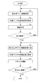
- FIG. 9 shows the procedure of the work taking-out method performed by the taking-out system 1.
- a step of acquiring a plurality of work Ws and a two-dimensional camera image of the surrounding environment for teaching by the user (step S1: a step of acquiring work information for teaching) and a step of displaying the acquired two-dimensional camera image are displayed.
- a step of teaching at least a teaching position (step S2: teaching step), which is a taking-out position of a target work Wo to be taken out from a plurality of work Ws, and a learning input in which teaching data obtained by the teaching step is added to a two-dimensional camera image.
- step S3 learning step
- step S4 teaching continuation confirmation step
- step S5 a step of acquiring work information for taking out work
- step S6 a step of acquiring work information for taking out work
- step S6 inference step
- step S6 take-out position of the target work inferred in the inferring step
- step S8 taking out continuation confirmation step
- the acquisition unit 51 may acquire only a plurality of two-dimensional camera images from the information acquisition device 10 and estimate the depth information thereof. Since the camera that captures the two-dimensional camera image is relatively inexpensive, the equipment cost of the information acquisition device 10 can be reduced and the introduction cost of the extraction system 1 can be reduced by using the two-dimensional camera image.
- the information acquisition device 10 is fixed to the movement mechanism or the hand of the robot, and the depth is obtained by using a plurality of two-dimensional camera images taken from different positions and angles together with the movement movement of the movement mechanism or the robot. Can be estimated. Specifically, it can be carried out by the same method as the method of estimating the depth information by one camera described above.
- the information acquisition device 10 is a distance sensor such as a sound wave sensor, a laser scanner, or a second unit. You may have a camera or the like to measure the distance to the work.
- the teaching unit 52 causes the display device 30 to input the two-dimensional extraction position of the target work Wo to be extracted or the extraction position with depth information on the two-dimensional camera image displayed on the display device 30.
- the 2D camera image is less likely to lose information as much as the depth image, and the state of the work W can be grasped in almost the same situation as when the user directly visually observes the actual object. Is.
- the taking-out posture can also be taught by the method as described above.
- the learning unit 53 includes information on the two-dimensional extraction position or depth of the target work Wo to be extracted, which has a desirable position having a near image of features common to the near image of the teaching position taught in the teaching step.
- a learning model that infers at least the extraction position of is generated by machine learning.
- step S4 it is confirmed whether or not to continue teaching, and if the teaching is continued, the process returns to step S1, and if the teaching is not continued, the process proceeds to step S5.
- the acquisition unit 51 acquires 2.5-dimensional image data (data including depth information for each pixel of the two-dimensional camera image and the two-dimensional camera image) from the information acquisition device 10. ..
- this extraction work information acquisition step two-dimensional camera images and depths of the current plurality of work W are acquired.
- the inference unit 54 infers at least the two-dimensional extraction target position of the target work Wo or the extraction target position with depth information according to the learning model. In this way, the reasoning unit 54 infers at least the target position of the target work Wo according to the learning model, so that the work W can be automatically taken out without asking the user's judgment.
- the taking-out posture is also taught, and when learned, the taking-out posture is also inferred.
- control unit 55 controls the robot 20 so that the take-out hand 21 holds and takes out the target work Wo.
- the control unit 55 adds depth information to the two-dimensional extraction position of the target inferred by the inference unit 54, or operates the extraction hand 21 appropriately according to the extraction position of the target inferred by the inference unit 54 with the depth information. Control the robot 20.
- step S8 it is confirmed whether or not to continue the take-out of the work W, and if the take-out is continued, the process returns to step S5, and if the take-out is not continued, the process ends.
- the work can be taken out appropriately by machine learning. Therefore, the extraction system 1 can be used for a new work without any special knowledge.
- FIG. 10 shows the configuration of the extraction system 1a according to the second embodiment.
- the take-out system 1a is a system that takes out the work W one by one from the existing area (above the tray T) of the plurality of work W.
- the same components as those of the retrieval system 1 of the first embodiment may be designated by the same reference numerals and duplicate description may be omitted.
- the retrieval system 1a includes an information acquisition device 10a that acquires three-dimensional point cloud data of the work W inside the tray T in which a plurality of work Ws are randomly overlapped and accommodated, a robot 20 that retrieves the work W from the tray T, and the robot 20.
- a display device 30 capable of displaying 3D point cloud data on a 3D view whose viewpoint can be changed, an input device 40 capable of input by a user, a robot 20, a control device 50a for controlling the display device 30 and the input device 40, and the like. To be equipped.
- the information acquisition device 10a acquires three-dimensional point cloud data of a target object (a plurality of works W and trays T). Examples of such an information acquisition device 10a include a stereo camera, a plurality of 3D laser scanners, a 3D laser scanner with a moving mechanism, and the like.
- the information acquisition device 10a may be configured to acquire a two-dimensional camera image in addition to the three-dimensional point cloud data of the target object (plurality of works W and tray T).
- Such an information acquisition device 10a selects one from a stereo camera, a plurality of 3D laser scanners, or a 3D laser scanner with a moving mechanism, and at the same time, a monochromatic camera, an RGB camera, an infrared camera, an ultraviolet camera, and an X-ray camera.
- one of the ultrasonic cameras can be selected and combined.
- the configuration may be such that only a stereo camera is used. In this case, the color information and the three-dimensional point cloud data of the grayscale image acquired by the stereo camera are used.
- the display device 30 may display the 3D point cloud data on the 3D view whose viewpoint can be changed by adding the color information obtained from the 2D camera image. Specifically, the color information of the pixel is added to each three-dimensional point corresponding to each pixel on the two-dimensional camera image, and the color is also displayed.
- the RGB color information acquired by the RGB camera may be displayed, but the black and white color information of the grayscale image acquired by the monochromatic camera may be displayed.
- the control device 50a can be realized by causing one or a plurality of computer devices including a CPU, a memory, a communication interface, and the like to execute an appropriate program.
- the control device 50a includes an acquisition unit 51a, a teaching unit 52a, a learning unit 53a, an inference unit 54a, and a control unit 55.
- the acquisition unit 51a acquires the three-dimensional point cloud data of the work existence area where a plurality of work Ws exist from the information acquisition device 10a, and when the information acquisition device 10a also acquires the two-dimensional camera image, the two-dimensional camera image is also obtained. get. Further, the acquisition unit 51a may be configured to combine the measurement data of a plurality of 3D scanners constituting the information acquisition device 10a and perform calculation processing to generate one three-dimensional point cloud data.
- the teaching unit 52a displays the three-dimensional point group data acquired by the acquisition unit 51a or the three-dimensional point group data to which the color information obtained from the two-dimensional camera image is added by the display device 30 on the 3D view whose viewpoint can be changed.
- the user confirms the work and its surrounding environment three-dimensionally from a plurality of directions, preferably all directions, while changing the viewpoint on the 3D view by using the input device 40, and the object to be taken out in the plurality of works W. It is configured so that the teaching position, which is the three-dimensional extraction position of the work Wo, can be taught.
- the teaching unit 52a can perform teaching by designating or changing the viewpoint of the 3D view in response to an operation from the user by the input device 40 on the 3D view whose viewpoint can be changed. For example, by moving the mouse while clicking the right mouse button, the user can change the viewpoint of the 3D view displaying the 3D point cloud data, and 3D the work from multiple directions, preferably any direction. Check the shape and the situation around the work, stop the mouse movement operation at the desired viewpoint, and click the left mouse button to teach the desired three-dimensional position seen from this viewpoint. This makes it possible to confirm the shape of the side surface of the work, which cannot be confirmed from the two-dimensional image, the positional relationship between the target work and the work around it in the vertical direction, and the situation below the work.
- the teaching unit 52a is a 3D view whose viewpoint can be changed, and displays the 3D point group data to which the color information by the 2D camera image acquired by the acquisition unit 51a is added by the display device 30 and the user by using the input device 40. While changing the viewpoint on the 3D view, check the work and its surrounding environment three-dimensionally from multiple directions, preferably all directions, including color information, and take out the target work Wo in the multiple work Ws. It may be configured so that the teaching position, which is the three-dimensional extraction position of the above, can be taught. As a result, the user can correctly grasp the work features from the color information and give correct teaching.
- the boundary line between two adjacent boxes can be defined only from the 3D point cloud data. It is difficult to distinguish, and the user mistakenly judges that two adjacent boxes are one large size box, and mistakenly teaches to suck and take out the narrow gap near the central boundary line. Probability is high. If the position with a gap is taken by air suction, air will leak and the removal will fail. In such a situation, by displaying the 3D point cloud data with color information, the user can check the boundary line even when the boxes of different colors are densely packed, so that incorrect teaching can be prevented. Can be done.
- the teaching unit 52a has a 3D view of the 3D point cloud data viewed from the viewpoint specified by the user, and the 3D shape, size, and hand direction of the pair of gripping fingers 212 of the extraction hand 21.
- the three-dimensional virtual hand Pa that reflects the sex (three-dimensional posture), the center position, and the distance between the hands is displayed.
- the teaching unit 52a determines the type of the take-out hand 21, the number of gripping fingers 212, the size of the gripping fingers 212 (width x depth x height), the degree of freedom of the take-out hand 21, the operation limit value of the interval between the gripping fingers 212, and the like. May be configured so that can be specified.
- the virtual hand Pa may be displayed including a center point M indicating a three-dimensional extraction target position between the gripping fingers 212.
- the user changes the viewpoint of the 3D view as appropriate, designates the target work Wo as the viewpoint viewed from the diagonal side, and confirms the shape of the side surface of the target work Wo to be grasped. It is possible to teach an appropriate three-dimensional take-out position so as to grip the side surface where the recess is not present. Further, since the virtual hand Pa has the center point M, the user relatively easily teaches an appropriate teaching position for stable gripping by arranging the center point M near the center of gravity of the target work Wo. be able to.
- the teaching unit 52a may be configured to have an open / close degree of the take-out hand 21 when there are two or more contact positions of the take-out hand 21 with the work W.
- the gripping finger 212 interferes with the surrounding environment when the take-out hand 21 approaches the target work Wo. It is possible to easily grasp and teach an appropriate interval between the gripping fingers 212 (the degree of opening / closing of the take-out hand 21).
- the teaching unit 52a may be configured to teach the three-dimensional take-out posture when the take-out hand 21 takes out the work W. For example, when the work is taken out by the taking-out hand 21 having one suction pad 211, the three-dimensional taking-out position is taught by the click operation of the left button of the mouse by the above-mentioned method, and then the taught three-dimensional position and the radius r around it are taught.
- the three-dimensional plane which is the tangent plane centered on the teaching position, can be estimated by using the three-dimensional point group inside the upper half of the three-dimensional sphere toward the viewpoint side.
- One virtual three-dimensional coordinate system can be estimated with the upward normal direction toward the viewpoint side of the estimated tangent plane as the positive direction of the z-axis, the three-dimensional plane as the xy plane, and the teaching position as the origin.
- the deviation amount ⁇ x , ⁇ y , and ⁇ z of the angles around the x-axis, y-axis, and z-axis of the virtual three-dimensional coordinate system and the three-dimensional reference coordinate system that is the reference of the extraction operation are calculated, and the extraction hand 21
- the default teaching value for the three-dimensional take-out posture is used.
- a three-dimensional virtual hand Pa that reflects the three-dimensional shape and size of the take-out hand 21 can be drawn, for example, as the smallest three-dimensional cylinder including the take-out hand 21.
- the position and orientation of the 3D cylinder are determined and displayed so that the center of the bottom surface of the 3D cylinder coincides with the 3D teaching position and the 3D orientation of the 3D cylinder is the default teaching value. do. If the three-dimensional cylinder displayed in that posture interferes with the surrounding work, the user fine-tunes the default teaching postures ⁇ x , ⁇ y , and ⁇ z. Specifically, the adjustment bar of each parameter displayed on the teaching unit 52 is moved to adjust, or the value of each parameter is directly input and adjusted to avoid the interference.
- the take-out hand 21 When the take-out hand 21 goes to take out the work according to the three-dimensional take-out posture determined in this way, the take-out hand 21 approaches along the substantially normal direction of the curved surface of the work near the three-dimensional take-out position.
- the take-out hand 21 does not interfere with the surrounding work, and the suction pad 211 can stably obtain a larger contact area and take out the work without scattering the target work Wo from the initial position at the time of shooting. ..
- the teaching unit 52a displays at least one of the z-height (height from a predetermined reference position) and the degree of exposure of the virtual hand Pa with respect to the work W on the display device 30, so that the user can increase the z-height.
- the work W may be configured to teach the order of taking out the work W so as to preferentially take out the work W having a high degree of exposure.
- a 3D view whose viewpoint can be changed displayed on the display device 30, it is possible to confirm a plurality of workpieces in an overlapping state from various viewpoints and correctly grasp the vertical positional relationship and the degree of exposure of the workpieces.
- the teaching unit 52a By configuring the teaching unit 52a to display the relative z heights of the plurality of works W selected as candidates using the input device 40 (for example, by clicking the mouse) on the display device 30, the user can move up. It is possible to more easily determine the work W that is easy to take out and is located in. Furthermore, the work W, which is not limited to a high relative z height and a high degree of exposure, and which is considered to have a higher possibility of successful extraction from the user's own knowledge (knowledge, past experience and intuition), is taught. May be good.
- the take-out hand 21 approaches or takes out a work that does not easily interfere with the surroundings when taking out the work
- the work W is unbalanced by preferentially grasping the position close to the center of gravity G of the work W.
- the teaching may be given in consideration of the fact that it can be taken out safely without any problems.
- the teaching unit 52a teaches the approach direction by operably displaying the approach direction of the take-out hand 21 with respect to the target work Wo as shown in FIG. It may be configured.
- the take-out hand 21 may approach the target work Wo vertically from directly above.
- the gripping finger 212 comes into contact with the side surface of the target work Wo first to change the position and posture of the work.
- the teaching unit 52a is configured to be able to teach that the take-out hand 21 should approach in a direction inclined along the central axis of the target work Wo. Specifically, the teaching unit 52a approaches the three-dimensional position that is the starting point of the approach of the take-out hand 21 and the three-dimensional position that is the teaching position that the user grips the target work Wo in the viewpoint-changeable 3D view. It can be configured to be designated as the end point.
- the three-dimensional virtual hand Pa that reflects the three-dimensional shape and size of the take-out hand 21 at the start point and end point, respectively. Is displayed as the smallest cylinder including the take-out hand 21.
- the user checks the displayed 3D virtual hand Pa and its surrounding environment while changing the viewpoint of the 3D view and discovers that the take-out hand 21 may interfere with the surrounding work W in the specified approach direction, further. It is possible to add a waypoint of the approach between the start point and the end point and teach the approach direction as two or more steps so as to avoid the interference.
- the teaching unit 52a may be configured to teach the gripping force by the gripping finger. It may be carried out by the same method as the method for teaching the gripping force described in the first embodiment described above.
- the teaching unit 52a may be configured to teach the gripping stability of the take-out hand 21.
- the teaching unit 52a analyzes the frictional force acting during the contact between the gripping finger 212 and the target work Wo using the Coulomb friction model, and the gripping stability defined based on the Coulomb friction model.
- the analysis result of the index representing the above is graphically and numerically displayed on the display device 30. The user can adjust the three-dimensional take-out position and the three-dimensional take-out posture of the take-out hand 21 while visually confirming the result, and can teach to obtain higher gripping stability.
- the contact force f that does not exceed the normal component can be evaluated as a desirable contact force that does not cause slippage between the gripping finger 212 and the target work Wo.
- a desirable contact force is in the three-dimensional conical space shown in FIG.
- the gripping motion due to such a desirable contact force is higher without the gripping finger 212 slipping during gripping and distracting the position and posture of the target work Wo from the initial position at the time of shooting, and without slipping and dropping the target work Wo.
- the target work Wo can be gripped and taken out with gripping stability.
- a candidate group of desirable contact force f that does not cause slippage between the gripping finger 212 and the target work Wo is an apex angle based on the Coulomb friction coefficient ⁇ and the positive pressure f ⁇ .
- the contact force for stably gripping the target work Wo without causing slippage needs to exist inside this force conical space Sf. Since one moment around the center of gravity of the target work Wo is generated by any one contact force f in the force conical space Sf, the conical shape of the moment corresponding to the force conical space Sf of such a desirable contact force.
- Such a desirable moment conical space Sm is defined based on the Coulomb friction coefficient ⁇ , the positive pressure f ⁇ , and the distance vector from the center of gravity G of the target work Wo to each contact position, and the force conical space Sf is a basis vector. Is another three-dimensional conical vector space with different.
- the three-dimensional minimum convex hull Hm including all the moment conical spaces Smi of each of the plurality of contact positions is a stable candidate group of a desirable moment for stably gripping the target work Wo. That is, when the center of gravity G of the target work Wo exists inside the minimum convex packets Hf and Hm, the contact force generated between the gripping finger 212 and the target work Wo is in the above-mentioned stable candidate group of the force vector and is generated. Since the moment around the center of gravity of the target work Wo is in the above-mentioned moment stability candidate group, such gripping does not distract the position and orientation of the target work Wo from the initial position at the time of shooting, and the target is slipped. Since the work Wo is not dropped and the unintended rotational movement around the center of gravity of the target work Wo does not occur, it can be determined that the grip is stable.
- ⁇ is the shortest distance from the center of gravity G of the target work Wo to the boundary of the minimum convex hull Hf or Hm (the shortest distance to the boundary of the minimum convex hull Hf of force ⁇ f or the boundary of the minimum convex hull Hm of the moment.
- the Qo defined in this way can be used regardless of the number of gripping fingers 212 (total number of contact positions).
- the index indicating the gripping stability is at least one of the plurality of contact positions of the virtual hand Pa with respect to the target work Wo and the friction coefficient between the take-out hand 21 and the target work Wo at each contact position. It is defined using at least one of the volume of the minimum convex hull Hf and Hm calculated by using one and the shortest distance from the center of gravity G of the target work Wo to the boundary of the minimum convex hull.
- the teaching unit 52a numerically displays the calculation result of the gripping stability evaluation value Qo on the display device 30 when the user temporarily inputs the take-out position and the posture of the take-out hand 21.
- the user can confirm whether the gripping stability evaluation value Qo is appropriate in comparison with the threshold value displayed at the same time. It may be configured so that it is possible to select whether to determine the input take-out position and the posture of the take-out hand 21 as teaching data, or to correct the take-out position and the posture of the take-out hand 21 and re-input.
- the teaching unit 52a graphically displays the shortest distance ⁇ from the volume V of the minimum convex hull Hf and Hm and the center of gravity G of the target work Wo on the display device 30, thereby optimizing the teaching data so as to satisfy the threshold value. It may be configured to be intuitively easy to convert.
- the teaching unit 52a displays the three-dimensional point cloud data of the work W and the tray T on the 3D view whose viewpoint can be changed, and also displays the three-dimensional extraction position and the three-dimensional extraction posture taught by the user.
- the calculated three-dimensional minimum convex hull Hf and Hm, the volume and the shortest distance from the center of gravity of the work are graphically displayed numerically, and the volume for stable grip and the threshold of the shortest distance are presented to stabilize the grip. It may be configured to display the sex determination result. As a result, the user can visually confirm whether or not the center of gravity G of the target work Wo is inside Hf and Hm.
- the user When the user finds that the center of gravity G is off, the user changes the teaching position and teaching posture and clicks the recalculation button, and the minimum convex hulls Hf and Hm reflecting the new teaching position and teaching posture are graphically It will be updated and reflected.
- the user can teach the desired position and posture such that the center of gravity G of the target work Wo is inside Hf and Hm while visually confirming. While confirming the judgment result of the gripping stability, the user can change the teaching position and the teaching posture as necessary to teach so as to obtain higher gripping stability.
- the learning unit 53a infers the extraction position, which is the three-dimensional position of the target work Wo, by machine learning (supervised learning) based on the three-dimensional point cloud data and the learning input data including the teaching position, which is the three-dimensional extraction position. Generate a learning model to do. Specifically, the learning unit 53a uses a convolutional neural network to share the point cloud data in the vicinity of each three-dimensional position and the point cloud data in the vicinity of the teaching position in the three-dimensional point cloud data. A learning model that quantifies and judges the sex is generated, the three-dimensional position that has higher commonality with the teaching position is given a higher score and evaluated higher, and the take-out hand 21 should take the target position with higher priority. It may be inferred as.
- the learning unit 53a adds the teaching data including the teaching position which is the three-dimensional extraction position to the three-dimensional point group data and the two-dimensional camera image for learning input. Based on the data, a learning model that infers the three-dimensional extraction position of the target work Wo by machine learning (supervised learning) is generated. Specifically, the learning unit 53a uses a convolutional neural network to share the point cloud data in the vicinity of each three-dimensional position and the point cloud data in the vicinity of the teaching position in the three-dimensional point cloud data. Rule A is established to quantify and judge the sex.
- convolutional neural network (Convolutional Neural Network) is used to quantify and determine the commonality between the camera image in the vicinity of each pixel and the camera image in the vicinity of the teaching position in the two-dimensional camera image.
- a goal that the take-out hand 21 should take with higher priority by giving a higher score to the three-dimensional position that has been established and has a higher commonality with the teaching position that is comprehensively judged by rule A and rule B. It may be inferred as a position.
- the learning unit 53a infers the three-dimensional extraction posture of the target work Wo by machine learning based on the learning input data including these teaching data. Generate a learning model.
- the structure of the convolutional neural network of the learning unit 53a is Conv3D (3D convolutional operation), AvePooling3D (3D averaging pooling operation), UnPolling3D (3D pooling inverse operation), Batch Normalization (function that maintains data normality), It can include multiple layers such as ReLU (Activation Function to Prevent Vanishing Gradation Problem).
- Conv3D 3D convolutional operation
- AvePooling3D 3D averaging pooling operation
- UnPolling3D 3D pooling inverse operation
- Batch Normalization function that maintains data normality
- It can include multiple layers such as ReLU (Activation Function to Prevent Vanishing Gradation Problem).
- ReLU Activation Function to Prevent Vanishing Gradation Problem
- the weighting coefficient of each layer is updated and determined by learning so that the difference between the output prediction data and the teaching data gradually becomes smaller.
- the learning unit 53a evenly searches all three-dimensional positions on the input three-dimensional point cloud data as candidates, calculates all predicted scores at once in full size, and shares them with the teaching position. It is possible to generate a learning model that has a high possibility of obtaining a candidate position that is highly likely to be taken out by the take-out hand 21. By inputting in full size and outputting the predicted scores of all three-dimensional positions in full size in this way, the optimum candidate position can be found without omission.
- the depth and complexity of the layers of the specific convolutional neural network may be adjusted according to the size of the input three-dimensional point cloud data, the complexity of the work shape, and the like.
- the learning unit 53a is configured to determine the quality of the learning result by machine learning based on the above-mentioned learning input data and display the determination result on the teaching unit 52a, and the determination result is NG. Further, a plurality of learning parameters and adjustment hints may be displayed on the teaching unit 52a so that the user can adjust the learning parameters and perform re-learning. For example, a transition map or a distribution map of the learning accuracy with respect to the learning input data and the test data is displayed, and if the learning accuracy does not increase even if the learning progresses, or if it is lower than the threshold value, it can be determined as NG. In addition, it seems that the user does not teach whether the correct answer rate, recall rate, precision rate, etc.
- the adjustment hint is also displayed on the teaching unit 52a and presented to the user so that a high accuracy rate, a recall rate, and a precision rate can be obtained.
- the user can adjust the learning parameters and perform re-learning based on the adjustment hints presented. In this way, by presenting the judgment result and the adjustment hint of the learning result by the learning unit 53a to the user without performing the actual extraction experiment, it is possible to generate a highly reliable learning model in a short time. become.
- the learning unit 53a feeds back not only the teaching position taught by the teaching unit 52a but also the inference result of the three-dimensional extraction position inferred by the inference unit 54a described later to the above-mentioned learning input data, and changes the learning input.
- the above-mentioned learning input data is modified so that the three-dimensional extraction position having a low evaluation score in the inference result by the inference unit 54a is excluded from the teaching data, and machine learning is performed again based on the modified learning input data. You may adjust the learning model.
- the inference unit 54a performs feature analysis of the three-dimensional extraction position having a high evaluation score in the inference result, and although the user has not taught on the three-dimensional point cloud data, the inferred evaluation score is high in three dimensions.
- a three-dimensional position having a high degree of commonality with the extraction position of the above may be automatically assigned as a teaching position by internal processing. As a result, it is possible to correct the misjudgment of the user and generate a learning model with higher accuracy.
- the learning unit 53a obtains the inference result including the three-dimensional extraction posture inferred by the inference unit 54a, which will be described later, as the above-mentioned learning input data.
- the learning model may be adjusted by feeding back to the above and performing machine learning based on the changed learning input data to infer the three-dimensional extraction posture of the target work Wo.
- the above-mentioned learning input data is modified so as to exclude the three-dimensional extraction posture having a low evaluation score in the inference result by the inference unit 54a from the teaching data, and machine learning is performed again based on the modified learning input data. You may go and adjust the learning model.
- the inference unit 54a performs feature analysis such as a three-dimensional extraction posture having a high evaluation score in the inference result, and although it is not taught by the user on the three-dimensional point cloud data, the inferred evaluation score is high3.
- a label may be automatically added by internal processing so as to add something having a high degree of commonality with the dimension extraction posture to the teaching data.
- the learning unit 53a is a control result of the robot 20 extraction operation by the control unit 55 based on not only the three-dimensional extraction position taught by the teaching unit 52a but also the three-dimensional extraction position inferred by the inference unit 54a described later. That is, the learning model for inferring the three-dimensional extraction position of the target work Wo may be adjusted by performing machine learning based on the result information of the success or failure of the extraction operation of the target work Wo performed by using the robot 20. From this, even if the plurality of teaching positions taught by the user include more incorrect teaching positions, the user's judgment error is corrected by performing re-learning based on the result of the actual retrieval operation. It is possible to generate a learning model with even higher accuracy. In addition, with this function, it is possible to generate a learning model by automatic learning without prior instruction by the user by utilizing the success / failure result of the operation of picking up at a randomly determined take-out position.
- the learning unit 53a is a control unit based on the inference result including the three-dimensional extraction posture inferred by the inference unit 54a described later.
- Machine learning is performed based on the control result of the take-out operation of the robot 20 by 55, that is, the result information of the success or failure of the take-out operation of the target work Wo performed by using the robot 20, and the three-dimensional take-out posture of the target work Wo is further improved.
- the inferred learning model may be adjusted.
- the learning unit 53a extracts the target work Wo by the control unit 55 using the robot 20 based on the extraction position inferred by the inference unit 54a described later, the work is left behind in the tray T.
- the situation may also be configured to learn and adjust the learning model.
- the image data when the work W is left behind in the tray T is displayed on the teaching unit 52a so that the user can additionally teach the take-out position and the like.
- One such leftover image may be taught, but a plurality of such leftover images may be displayed.
- the data additionally taught in this way is also included in the learning input data, and learning is performed again to generate a learning model.
- a state in which the number of works in the tray T decreases with the taking-out operation and it becomes difficult to take out, for example, a state in which works close to the wall side or the corner side of the tray T are left behind is likely to appear.
- the overlapping state it is difficult to take out in that posture, for example, when the work posture or the work overlaps so that all the positions corresponding to the teaching positions are hidden behind the camera and are not captured by the camera.
- it may interfere with the hand and the tray T or other work if it is taken out because it is quite slanted.
- the trained model cannot handle the overlapping state and work state of these leftovers.
- the user additionally teaches another position on the side far from the wall or the corner, another position that is not hidden and is reflected in the camera, or another position that is not so slanted, and the additionally taught data. This problem can be solved by putting in and learning again.
- the inference unit 54a infers at least the three-dimensional extraction target position of the target work Wo to be extracted based on the learning model generated by the learning unit 53a using the three-dimensional point cloud data acquired by the acquisition unit 51a as input data. ..
- the posture of the take-out hand 21 when taking out the target work Wo is inferred based on the learning model.
- the inference unit 54a uses the 3D point group data acquired by the acquisition unit 51a and the 2D camera image as input data, and is based on the learning model generated by the learning unit 53a. Then, at least the three-dimensional extraction target position of the target work Wo to be extracted is inferred.
- the three-dimensional take-out posture of the take-out hand 21 is also taught, the three-dimensional take-out posture of the take-out hand 21 when taking out the target work Wo is also inferred based on the learning model.
- the inference unit 54a when the inference unit 54a infers the three-dimensional extraction positions of a plurality of target work Wo to be extracted from the three-dimensional point cloud data, the inference unit 54a extracts the target work Wo into a plurality of target work Wo based on the learning model generated by the learning unit 53a. You may set the priority.
- the inference unit 54a Infers the 3D extraction position of a plurality of target work Wo to be extracted from the 3D point group data and the 2D camera image, and the learning unit 53a infers. Based on the generated learning model, the priority of extraction may be set for a plurality of target work Wo.
- the teaching unit 52a may be configured to teach the take-out position of the work W based on the CAD model information of the work W. That is, the teaching unit 52a collates the three-dimensional point cloud data with the three-dimensional CAD model, and arranges the three-dimensional CAD model so as to match the three-dimensional point cloud data. As a result, even if there is a part of the area where the 3D point cloud data could not be acquired due to the performance limitation of the information acquisition device 10a, the features in another area where the data could already be acquired (for example, a plane or a hole, etc.) By matching the groove etc.
- the area where the data could not be acquired is interpolated and displayed from the 3D CAD model, and the user can easily visually check the interpolated 3D data.
- the frictional force acting on the gripping finger 212 of the take-out hand 21 may be analyzed based on the three-dimensional CAD model arranged so as to match the three-dimensional point cloud data.
- the direction of the contact surface is wrong due to the incompleteness of the 3D point cloud data, or the unstable edge part is sandwiched and taken out, and it is erroneously taught to take out by adsorption to features such as holes and grooves. It is possible to prevent such problems and give correct teaching.
- the teaching unit 52a may be configured to teach the three-dimensional take-out posture of the work W based on the three-dimensional CAD model information of the work W. For example, using the method of matching with the 3D CAD model of the work W described above, the 3D extraction posture of the work having symmetry is based on the 3D CAD model arranged so as to match the 3D point cloud data. It is possible to eliminate the teaching error caused by the incompleteness of the 3D point cloud data.
- the teaching unit 52a may be configured to display a simple mark such as a dot, a circle, or a cross at the take-out position taught by the user without displaying the above-mentioned three-dimensional virtual hand P for teaching.
- the teaching unit 52a does not display the above-mentioned three-dimensional virtual hand P, but numerically displays the z-coordinate value of the three-dimensional position on the three-dimensional point cloud data pointed by the arrow pointer of the mouse in real time to teach. May be configured to do.
- the user moves the mouse to the three-dimensional positions of multiple candidates, checks and compares the z-coordinate values of each displayed position, and compares the relative vertical positions. You will definitely be able to teach the correct take-out order.
- the work can be appropriately extracted by machine learning. Therefore, the extraction system 1a can be used for the new work W without any special knowledge.
- the retrieval system and method according to the present disclosure are not limited to the above-described embodiment. Further, the effects described in the above-described embodiment are merely a list of the most preferable effects arising from the extraction system and method according to the present disclosure, and the effects of the extraction system and method according to the present disclosure are described in the above-described embodiment. Not limited to what is described.
- the take-out device teaches a teaching position for taking out the target work using 2.5-dimensional image data or a two-dimensional camera image, or teaches a teaching position for taking out the target work using three-dimensional point cloud data.
- it may be configured to be able to select whether to teach the teaching position for extracting the target work using the three-dimensional point cloud data and the two-dimensional camera image, and further, the teaching for extracting the target work using the distance image. It may be configured to be selectable to teach the position.
- 1,1a Extraction system 10 10a Information acquisition device 20
- Robot 21 Extraction hand 211
- Suction pad 212 Grip finger 30
- Display device 40 Input device 50, 50a Control device 51, 51a Acquisition unit 52, 52a Teaching unit 53, 53a Learning unit 54, 54a Reasoning unit 55
- Control unit P Pa Virtual hand W work Wo Target work
Landscapes
- Engineering & Computer Science (AREA)
- Robotics (AREA)
- Mechanical Engineering (AREA)
- Physics & Mathematics (AREA)
- Theoretical Computer Science (AREA)
- General Physics & Mathematics (AREA)
- General Health & Medical Sciences (AREA)
- General Engineering & Computer Science (AREA)
- Biophysics (AREA)
- Computational Linguistics (AREA)
- Data Mining & Analysis (AREA)
- Evolutionary Computation (AREA)
- Artificial Intelligence (AREA)
- Molecular Biology (AREA)
- Computing Systems (AREA)
- Biomedical Technology (AREA)
- Life Sciences & Earth Sciences (AREA)
- Mathematical Physics (AREA)
- Software Systems (AREA)
- Health & Medical Sciences (AREA)
- Automation & Control Theory (AREA)
- Multimedia (AREA)
- Manipulator (AREA)
- Image Analysis (AREA)
Abstract
Description
以下、本開示に係る取り出しシステムの実施形態について図面を参照しながら説明する。図1に、第1実施形態に係る取り出しシステム1の構成を示す。取り出しシステム1は、複数のワークWの存在領域(コンテナCの内部)からワークWを1つずつ取り出すシステムである。
図10に、第2実施形態に係る取り出しシステム1aの構成を示す。取り出しシステム1aは、複数のワークWの存在領域(トレイTの上)からワークWを1つずつ取り出すシステムである。第2実施形態の取り出しシステム1aについて、第1実施形態の取り出しシステム1と同様の構成要素には、同じ符号を付して重複する説明を省略することがある。
10,10a 情報取得装置
20 ロボット
21 取り出しハンド
211 吸着パッド
212 把持指
30 表示装置
40 入力装置
50,50a 制御装置
51,51a 取得部
52,52a 教示部
53,53a 学習部
54,54a 推論部
55 制御部
P,Pa 仮想ハンド
W ワーク
Wo 対象ワーク
Claims (20)
- ハンドを有し、前記ハンドを用いてワークを取り出し可能なロボットと、
複数のワークの存在領域の2次元カメラ画像を取得する取得部と、
前記2次元カメラ画像を表示するとともに、複数の前記ワークのうち前記ハンドで取り出すべき対象ワークの取り出し位置を教示可能な教示部と、
前記2次元カメラ画像と教示された前記取り出し位置に基づいて、学習モデルを生成する学習部と、
前記学習モデルと2次元カメラ画像に基づいて前記対象ワークの取り出し位置を推論する推論部と、
推論された前記取り出し位置に基づいて、前記ハンドにより前記対象ワークを取り出すように前記ロボットを制御する制御部と、
を備える、取り出しシステム。 - 前記取得部は、前記2次元カメラ画像の画素毎の深度情報を含む画像データを取得する請求項1に記載の取り出しシステム。
- 前記教示部は、前記2次元カメラ画像又は前記画像データの少なくとも一方を表示可能である請求項2に記載の取り出しシステム。
- 前記学習部は、前記画像データに基づいて、前記学習モデルを生成し、
前記推論部は、前記学習モデルと画像データに基づいて、前記対象ワークの取り出し位置を推論する請求項2又は3に記載の取り出しシステム。 - 前記教示部は、前記ハンドの2次元形状又はその一部、前記ハンドのサイズ、前記ハンドの位置、前記ハンドの姿勢、及び前記ハンドの間隔の情報の少なくとも1つを含む2次元仮想ハンドを表示可能である請求項1乃至4の何れか1項に記載の取り出しシステム。
- 前記教示部は、前記画像データの前記深度情報に応じてサイズが変化する2次元仮想ハンドを表示可能である請求項2乃至4の何れか1項に記載の取り出しシステム。
- 前記教示部は、前記ワークに対する前記2次元仮想ハンドの姿勢、前記ワークの取り出し順番、前記2次元仮想ハンドの開閉度、前記2次元仮想ハンドの把持力、及び前記2次元仮想ハンドの把持安定性のうち少なくとも何れかのパラメータを教示可能であり、
前記学習部は、教示された前記パラメータに基づいて前記学習モデルを生成し、
前記推論部は、生成された前記学習モデルと2次元カメラ画像に基づいて前記対象ワークのパラメータを推論する請求項5又は6に記載の取り出しシステム。 - 前記把持安定性は、前記2次元仮想ハンドの前記ワークに対する接触位置、及び前記接触位置における前記ハンドと前記ワークの間の摩擦係数のうち少なくとも1つを用いて定義される請求項7に記載の取り出しシステム。
- 前記学習部は、前記2次元カメラ画像を含む学習データに基づく学習の結果を用いて良否判定を行い、前記良否判定の結果を前記教示部に出力し、前記良否判定の結果が否である場合に、学習用パラメータ及び調整ヒントを前記教示部に出力する請求項1乃至8の何れか1項に記載の取り出しシステム。
- ハンドを有し、前記ハンドを用いてワークを取り出し可能なロボットと、
複数のワークの存在領域の3次元点群データを取得する取得部と、
3Dビューの中に前記3次元点群データを表示するとともに、複数の前記ワークと周囲環境を複数の方向から表示可能であり、複数の前記ワークのうち前記ハンドで取り出すべき対象ワークの取り出し位置を教示可能な教示部と、
前記3次元点群データと教示された前記取り出し位置に基づいて、学習モデルを生成する学習部と、
前記学習モデルと3次元点群データに基づいて、前記対象ワークの取り出し位置を推論する推論部と、
推論された前記取り出し位置に基づいて、前記ハンドにより前記対象ワークを取り出すように前記ロボットを制御する制御部と、
を備える、取り出しシステム。 - 前記取得部は、複数の前記ワークの存在領域の2次元カメラ画像を取得し、
前記教示部は、前記3次元点群データに前記2次元カメラ画像の情報を加えて表示し、
前記学習部は、前記2次元カメラ画像に基づいて前記学習モデルを生成し、
前記推論部は、2次元カメラ画像に基づいて前記対象ワークの取り出し位置を推論する請求項10に記載の取り出しシステム。 - 前記教示部は、前記ハンドの3次元形状又はその一部、前記ハンドのサイズ、前記ハンドの位置、前記ハンドの姿勢、及び前記ハンドの間隔の情報の少なくとも1つを含む3次元仮想ハンドを表示可能である請求項10又は11に記載の取り出しシステム。
- 前記教示部は、前記ワークに対する前記3次元仮想ハンドの姿勢、前記ワークの取り出し順番、前記ワークに対する前記3次元仮想ハンドのアプローチ方向、前記ワークに対する前記3次元仮想ハンドの開閉度、前記3次元仮想ハンドの把持力、及び前記ワークに対する前記3次元仮想ハンドの把持安定性のうち少なくとも何れかのパラメータを教示可能であり、
前記学習部は、教示された前記パラメータに基づいて前記学習モデルを作成し、
前記推論部は、生成された前記学習モデルと3次元点群データに基づいて前記対象ワークのパラメータを推論する請求項12に記載の取り出しシステム。 - 前記把持安定性は、前記3次元仮想ハンドの前記ワークに対する接触位置、及び前記接触位置における前記ハンドと前記ワークの間の摩擦係数のうち少なくとも1つを用いて定義される請求項13に記載の取り出しシステム。
- 前記学習部は、前記3次元点群データを含む学習データに基づく学習の結果を用いて良否判定を行い、前記良否判定の結果を前記教示部に出力し、前記良否判定の結果が否である場合に、学習用パラメータ及び調整ヒントを前記教示部に出力する請求項10乃至14の何れか1項に記載の取り出しシステム。
- 前記学習部は、前記推論部に推論された結果情報に基づいて前記学習モデルを調整する、請求項1乃至15の何れか1項に記載の取り出しシステム。
- 前記学習部は、前記ロボットの取り出し動作の結果情報に基づいて、前記学習モデルを生成する、請求項1乃至16の何れか1項に記載の取り出しシステム。
- 前記教示部は、前記ワークのCADモデル情報に基づいて教示を行うよう構成される、請求項1乃至17の何れか1項に記載の取り出しシステム。
- ハンドによりワークを取り出し可能なロボットを用いて、複数のワークの存在領域から対象ワークを取り出す方法であって、
前記複数のワークの存在領域の2次元カメラ画像を取得する工程と、
前記2次元カメラ画像を表示するとともに、複数の前記ワークのうち前記ハンドで取り出すべき対象ワークの取り出し位置を教示する工程と、
前記2次元カメラ画像と教示された前記取り出し位置に基づいて、学習モデルを生成する工程と、
前記学習モデルと2次元カメラ画像に基づいて前記対象ワークの取り出し位置を推論する工程と、
推論された前記取り出し位置に基づいて、前記ハンドにより前記対象ワークを取り出すように前記ロボットを制御させる工程と、
を備える、方法。 - ハンドによりワークを取り出し可能なロボットを用いて、複数のワークの存在領域から対象ワークを取り出す方法であって、
前記複数のワークの存在領域の3次元点群データを取得する工程と、
3Dビューの中に前記3次元点群データを表示するとともに、複数の前記ワークと周囲環境を複数の方向から表示可能であり、複数の前記ワークのうち前記ハンドで取り出すべき対象ワークの取り出し位置を教示する工程と、
前記3次元点群データと教示された前記取り出し位置に基づいて、学習モデルを生成する工程と、
前記学習モデルと3次元点群データに基づいて前記対象ワークの取り出し位置を推論する工程と、
推論された前記取り出し位置に基づいて、前記ハンドにより前記対象ワークを取り出すように前記ロボットを制御させる工程と、
を備える、方法。
Priority Applications (4)
| Application Number | Priority Date | Filing Date | Title |
|---|---|---|---|
| CN202180017974.9A CN115210049A (zh) | 2020-03-05 | 2021-03-01 | 取出系统以及方法 |
| US17/905,403 US20230125022A1 (en) | 2020-03-05 | 2021-03-01 | Picking system and method |
| JP2022504356A JP7481427B2 (ja) | 2020-03-05 | 2021-03-01 | 取り出しシステム及び方法 |
| DE112021001419.6T DE112021001419B4 (de) | 2020-03-05 | 2021-03-01 | Aufnahmesystem und Verfahren |
Applications Claiming Priority (2)
| Application Number | Priority Date | Filing Date | Title |
|---|---|---|---|
| JP2020037638 | 2020-03-05 | ||
| JP2020-037638 | 2020-03-05 |
Publications (1)
| Publication Number | Publication Date |
|---|---|
| WO2021177239A1 true WO2021177239A1 (ja) | 2021-09-10 |
Family
ID=77614276
Family Applications (1)
| Application Number | Title | Priority Date | Filing Date |
|---|---|---|---|
| PCT/JP2021/007734 Ceased WO2021177239A1 (ja) | 2020-03-05 | 2021-03-01 | 取り出しシステム及び方法 |
Country Status (5)
| Country | Link |
|---|---|
| US (1) | US20230125022A1 (ja) |
| JP (1) | JP7481427B2 (ja) |
| CN (1) | CN115210049A (ja) |
| DE (1) | DE112021001419B4 (ja) |
| WO (1) | WO2021177239A1 (ja) |
Cited By (9)
| Publication number | Priority date | Publication date | Assignee | Title |
|---|---|---|---|---|
| CN114882109A (zh) * | 2022-04-27 | 2022-08-09 | 天津新松机器人自动化有限公司 | 一种面向遮挡、杂乱场景下的机器人抓取检测方法及系统 |
| EP4148374A1 (en) * | 2021-09-13 | 2023-03-15 | Toyota Jidosha Kabushiki Kaisha | Workpiece holding apparatus, workpiece holding method, program, and control apparatus |
| WO2023163219A1 (ja) * | 2022-02-28 | 2023-08-31 | 京セラ株式会社 | 情報処理装置、ロボット制御システム及びプログラム |
| US20230364798A1 (en) * | 2022-05-12 | 2023-11-16 | Canon Kabushiki Kaisha | Information processing method, image processing method, robot control method, product manufacturing method, information processing apparatus, image processing apparatus, robot system, and recording medium |
| JP2024028219A (ja) * | 2022-08-17 | 2024-03-01 | タタ コンサルタンシー サービシズ リミテッド | ポイント・クラウド・ベース把持計画フレームワークのための方法及びシステム |
| CN117881616A (zh) * | 2021-10-07 | 2024-04-12 | 株式会社富士 | 异物去除系统 |
| JPWO2024176359A1 (ja) * | 2023-02-21 | 2024-08-29 | ||
| WO2025005127A1 (ja) * | 2023-06-30 | 2025-01-02 | 京セラ株式会社 | 処理装置、ロボット制御装置、ロボットシステム及びプログラム |
| JP7812173B1 (ja) * | 2024-11-27 | 2026-02-09 | 法奥意威(蘇州)机器人系統有限公司 | 深型容器内のワークのピッキング方法、装置および電子機器 |
Families Citing this family (18)
| Publication number | Priority date | Publication date | Assignee | Title |
|---|---|---|---|---|
| WO2020184101A1 (ja) * | 2019-03-13 | 2020-09-17 | 日本電気株式会社 | 情報処理装置、駆動制御方法およびプログラム記憶媒体 |
| US20210016454A1 (en) * | 2019-07-16 | 2021-01-21 | Kindred Systems Inc. | Control of modular end-of-arm tooling for robotic manipulators |
| EP4063081A1 (de) * | 2021-03-22 | 2022-09-28 | Siemens Aktiengesellschaft | Verfahren zum ermitteln von steuerungsdaten für eine greifeinrichtung zum greifen eines gegenstands |
| JP7644341B2 (ja) * | 2021-04-13 | 2025-03-12 | 株式会社デンソーウェーブ | 機械学習装置及びロボットシステム |
| US20240198515A1 (en) * | 2021-05-25 | 2024-06-20 | Siemens Aktiengesellschaft | Transformation for covariate shift of grasp neural networks |
| IT202100019049A1 (it) * | 2021-07-19 | 2023-01-19 | Fondazione St Italiano Tecnologia | Pinza di presa e suo metodo di controllo |
| US20230092975A1 (en) * | 2021-09-21 | 2023-03-23 | Nimble Robotics, Inc. | Systems And Methods For Teleoperated Robot |
| WO2023062941A1 (ja) * | 2021-10-15 | 2023-04-20 | ソニーグループ株式会社 | 把持制御装置、および把持制御方法 |
| US12102393B2 (en) * | 2021-11-16 | 2024-10-01 | Metal Industries Research & Development Centre | Surgical robotic arm control system and control method thereof |
| JP2023087271A (ja) * | 2021-12-13 | 2023-06-23 | コニカミノルタ株式会社 | 姿勢判定方法、プログラム及び部品供給装置 |
| US20230278213A1 (en) * | 2022-03-01 | 2023-09-07 | Autodesk, Inc. | Techniques for adaptive robotic assembly |
| DE102022207847A1 (de) * | 2022-07-29 | 2024-02-01 | Robert Bosch Gesellschaft mit beschränkter Haftung | Verfahren zum Steuern eines Roboters zum Manipulieren, insbesondere Aufnehmen, eines Objekts |
| US20240058953A1 (en) * | 2022-08-19 | 2024-02-22 | AMP Robotics Corporation | Object picking optimization |
| DE102023201031A1 (de) * | 2023-02-08 | 2024-08-08 | Kuka Deutschland Gmbh | Transfer von durch Roboter gehaltenen Objekten von Aufnahmeposen zu Zielposen |
| WO2024177627A1 (en) * | 2023-02-22 | 2024-08-29 | Siemens Aktiengesellschaft | Scale aware neural network for robotic grasping |
| CN117649542B (zh) * | 2023-11-30 | 2024-07-16 | 中科海拓(无锡)科技有限公司 | 一种基于主动视觉的动车运维机器人自动示教方法 |
| DE102024206911A1 (de) * | 2024-07-23 | 2026-01-29 | Robert Bosch Gesellschaft mit beschränkter Haftung | Verfahren zum Bestimmen von Objektposen |
| CN119425900A (zh) * | 2024-11-07 | 2025-02-14 | 福州大学 | 一种球磨车间多层钢球无序抓取装置及方法 |
Citations (6)
| Publication number | Priority date | Publication date | Assignee | Title |
|---|---|---|---|---|
| JPH11202923A (ja) * | 1998-01-20 | 1999-07-30 | Okuma Corp | 生産システム |
| JP2009056513A (ja) * | 2007-08-29 | 2009-03-19 | Toshiba Corp | 把持位置姿勢決定システムおよび把持位置姿勢決定方法 |
| JP2018144228A (ja) * | 2018-06-27 | 2018-09-20 | セイコーエプソン株式会社 | ロボット制御装置、ロボット、ロボットシステム、教示方法、及びプログラム |
| JP2019056966A (ja) * | 2017-09-19 | 2019-04-11 | 株式会社東芝 | 情報処理装置、画像認識方法および画像認識プログラム |
| WO2019069361A1 (ja) * | 2017-10-03 | 2019-04-11 | 三菱電機株式会社 | 把持位置姿勢教示装置、把持位置姿勢教示方法及びロボットシステム |
| WO2020022302A1 (ja) * | 2018-07-26 | 2020-01-30 | Ntn株式会社 | 把持装置 |
Family Cites Families (8)
| Publication number | Priority date | Publication date | Assignee | Title |
|---|---|---|---|---|
| JP5788460B2 (ja) * | 2013-11-05 | 2015-09-30 | ファナック株式会社 | バラ積みされた物品をロボットで取出す装置及び方法 |
| DE202017106506U1 (de) * | 2016-11-15 | 2018-04-03 | Google Llc | Einrichtung für tiefes Maschinenlernen zum Robotergreifen |
| JP6474179B2 (ja) * | 2017-07-30 | 2019-02-27 | 国立大学法人 奈良先端科学技術大学院大学 | 学習データセット作製方法、並びに、物体認識及び位置姿勢推定方法 |
| JP6608890B2 (ja) * | 2017-09-12 | 2019-11-20 | ファナック株式会社 | 機械学習装置、ロボットシステム及び機械学習方法 |
| JP6695843B2 (ja) * | 2017-09-25 | 2020-05-20 | ファナック株式会社 | 装置、及びロボットシステム |
| US10766149B2 (en) * | 2018-03-23 | 2020-09-08 | Amazon Technologies, Inc. | Optimization-based spring lattice deformation model for soft materials |
| JP6787966B2 (ja) * | 2018-10-02 | 2020-11-18 | ファナック株式会社 | 拡張現実と複合現実を用いたロボット制御装置及び表示装置 |
| CN110211180A (zh) * | 2019-05-16 | 2019-09-06 | 西安理工大学 | 一种基于深度学习的机械臂自主抓取方法 |
-
2021
- 2021-03-01 US US17/905,403 patent/US20230125022A1/en not_active Abandoned
- 2021-03-01 CN CN202180017974.9A patent/CN115210049A/zh not_active Withdrawn
- 2021-03-01 WO PCT/JP2021/007734 patent/WO2021177239A1/ja not_active Ceased
- 2021-03-01 DE DE112021001419.6T patent/DE112021001419B4/de active Active
- 2021-03-01 JP JP2022504356A patent/JP7481427B2/ja active Active
Patent Citations (6)
| Publication number | Priority date | Publication date | Assignee | Title |
|---|---|---|---|---|
| JPH11202923A (ja) * | 1998-01-20 | 1999-07-30 | Okuma Corp | 生産システム |
| JP2009056513A (ja) * | 2007-08-29 | 2009-03-19 | Toshiba Corp | 把持位置姿勢決定システムおよび把持位置姿勢決定方法 |
| JP2019056966A (ja) * | 2017-09-19 | 2019-04-11 | 株式会社東芝 | 情報処理装置、画像認識方法および画像認識プログラム |
| WO2019069361A1 (ja) * | 2017-10-03 | 2019-04-11 | 三菱電機株式会社 | 把持位置姿勢教示装置、把持位置姿勢教示方法及びロボットシステム |
| JP2018144228A (ja) * | 2018-06-27 | 2018-09-20 | セイコーエプソン株式会社 | ロボット制御装置、ロボット、ロボットシステム、教示方法、及びプログラム |
| WO2020022302A1 (ja) * | 2018-07-26 | 2020-01-30 | Ntn株式会社 | 把持装置 |
Non-Patent Citations (1)
| Title |
|---|
| SHINDOH, TOMONORI: "YASKAWA ELECTRIC uses deep learning for grasping three types of work, MITSUBISHI ELECTRIC uses reinforcement learning for adjusting the interdigitation parameters", NIKKEI ROBOTICS, 10 December 2017 (2017-12-10) * |
Cited By (13)
| Publication number | Priority date | Publication date | Assignee | Title |
|---|---|---|---|---|
| EP4148374A1 (en) * | 2021-09-13 | 2023-03-15 | Toyota Jidosha Kabushiki Kaisha | Workpiece holding apparatus, workpiece holding method, program, and control apparatus |
| US12479094B2 (en) | 2021-09-13 | 2025-11-25 | Toyota Jidosha Kabushiki Kaisha | Workpiece holding apparatus, workpiece holding method, program, and control apparatus capable of preventing a selected workpiece from being attracted and held by other workpieces |
| CN117881616A (zh) * | 2021-10-07 | 2024-04-12 | 株式会社富士 | 异物去除系统 |
| JPWO2023163219A1 (ja) * | 2022-02-28 | 2023-08-31 | ||
| WO2023163219A1 (ja) * | 2022-02-28 | 2023-08-31 | 京セラ株式会社 | 情報処理装置、ロボット制御システム及びプログラム |
| CN114882109A (zh) * | 2022-04-27 | 2022-08-09 | 天津新松机器人自动化有限公司 | 一种面向遮挡、杂乱场景下的机器人抓取检测方法及系统 |
| US20230364798A1 (en) * | 2022-05-12 | 2023-11-16 | Canon Kabushiki Kaisha | Information processing method, image processing method, robot control method, product manufacturing method, information processing apparatus, image processing apparatus, robot system, and recording medium |
| JP2024028219A (ja) * | 2022-08-17 | 2024-03-01 | タタ コンサルタンシー サービシズ リミテッド | ポイント・クラウド・ベース把持計画フレームワークのための方法及びシステム |
| JP7820337B2 (ja) | 2022-08-17 | 2026-02-25 | タタ コンサルタンシー サービシズ リミテッド | ポイント・クラウド・ベース把持計画フレームワークのための方法及びシステム |
| JPWO2024176359A1 (ja) * | 2023-02-21 | 2024-08-29 | ||
| WO2024176359A1 (ja) * | 2023-02-21 | 2024-08-29 | ファナック株式会社 | 位置補正装置、ロボットシステムおよび位置補正プログラム |
| WO2025005127A1 (ja) * | 2023-06-30 | 2025-01-02 | 京セラ株式会社 | 処理装置、ロボット制御装置、ロボットシステム及びプログラム |
| JP7812173B1 (ja) * | 2024-11-27 | 2026-02-09 | 法奥意威(蘇州)机器人系統有限公司 | 深型容器内のワークのピッキング方法、装置および電子機器 |
Also Published As
| Publication number | Publication date |
|---|---|
| CN115210049A (zh) | 2022-10-18 |
| DE112021001419B4 (de) | 2026-02-12 |
| DE112021001419T5 (de) | 2022-12-22 |
| JP7481427B2 (ja) | 2024-05-10 |
| JPWO2021177239A1 (ja) | 2021-09-10 |
| US20230125022A1 (en) | 2023-04-20 |
Similar Documents
| Publication | Publication Date | Title |
|---|---|---|
| WO2021177239A1 (ja) | 取り出しシステム及び方法 | |
| US11518625B2 (en) | Handling device, control device, and holding method | |
| JP7128933B2 (ja) | 画像処理装置 | |
| JP6823502B2 (ja) | ロボット設定装置、ロボット設定方法、ロボット設定プログラム及びコンピュータで読み取り可能な記録媒体並びに記録した機器 | |
| JP5281414B2 (ja) | ワーク自動把持のための方法及びシステム | |
| JP5458885B2 (ja) | 物体検出方法と物体検出装置およびロボットシステム | |
| US7280687B2 (en) | Device for detecting position/orientation of object | |
| CN114845844A (zh) | 信息处理装置、工件识别装置及工件取出装置 | |
| US20230297068A1 (en) | Information processing device and information processing method | |
| WO2023092519A1 (zh) | 抓取控制方法、装置、电子设备和存储介质 | |
| EP4261636A1 (en) | Processing device, processing system, head mounted display, processing method, program, and storage medium | |
| KR20220067719A (ko) | 딥러닝과 마커를 이용한 비전인식을 통한 로봇 제어장치 및 그 방법 | |
| JP2018126862A (ja) | 干渉判定装置、干渉判定方法、コンピュータプログラム | |
| CN116901054A (zh) | 识别位置姿态的方法、系统以及存储介质 | |
| JP6237122B2 (ja) | ロボット、画像処理方法及びロボットシステム | |
| CN117795552A (zh) | 用于进行基于视觉的工具定位的方法和装置 | |
| CN114845845A (zh) | 把持装置、控制方法和程序 | |
| US12567241B2 (en) | Method for generating training data used to learn machine learning model, system, and non-transitory computer-readable storage medium storing computer program | |
| WO2023243051A1 (ja) | ワーク取り出しシステム | |
| US20250121502A1 (en) | System and method for grasp synthesis of non-occluded and occluded objects with a camera-equipped robot manipulator | |
| RU2800443C1 (ru) | Способ выполнения манипуляции с объектом | |
| KR102926904B1 (ko) | Ai 기반 머신 비전 기술을 적용시킨 오븐 힌지 색상 구분 장치 및 방법 | |
| JPH07160881A (ja) | 環境認識装置 | |
| JP2021003782A (ja) | 物体認識処理装置、物体認識処理方法およびピッキング装置 | |
| WO2026029177A1 (ja) | 処理装置、ロボットシステム及びプログラム |
Legal Events
| Date | Code | Title | Description |
|---|---|---|---|
| 121 | Ep: the epo has been informed by wipo that ep was designated in this application |
Ref document number: 21764162 Country of ref document: EP Kind code of ref document: A1 |
|
| ENP | Entry into the national phase |
Ref document number: 2022504356 Country of ref document: JP Kind code of ref document: A |
|
| WWE | Wipo information: entry into national phase |
Ref document number: 112021001419 Country of ref document: DE |
|
| 122 | Ep: pct application non-entry in european phase |
Ref document number: 21764162 Country of ref document: EP Kind code of ref document: A1 |
|
| WWG | Wipo information: grant in national office |
Ref document number: 112021001419 Country of ref document: DE |