WO2021176683A1 - 光ファイバセンシングシステム、光ファイバセンシング方法、及び光ファイバセンシング装置 - Google Patents
光ファイバセンシングシステム、光ファイバセンシング方法、及び光ファイバセンシング装置 Download PDFInfo
- Publication number
- WO2021176683A1 WO2021176683A1 PCT/JP2020/009653 JP2020009653W WO2021176683A1 WO 2021176683 A1 WO2021176683 A1 WO 2021176683A1 JP 2020009653 W JP2020009653 W JP 2020009653W WO 2021176683 A1 WO2021176683 A1 WO 2021176683A1
- Authority
- WO
- WIPO (PCT)
- Prior art keywords
- monitoring target
- optical fiber
- sensing
- information
- sensing information
- Prior art date
- Legal status (The legal status is an assumption and is not a legal conclusion. Google has not performed a legal analysis and makes no representation as to the accuracy of the status listed.)
- Ceased
Links
Images








Classifications
-
- G—PHYSICS
- G01—MEASURING; TESTING
- G01H—MEASUREMENT OF MECHANICAL VIBRATIONS OR ULTRASONIC, SONIC OR INFRASONIC WAVES
- G01H9/00—Measuring mechanical vibrations or ultrasonic, sonic or infrasonic waves by using radiation-sensitive means, e.g. optical means
- G01H9/004—Measuring mechanical vibrations or ultrasonic, sonic or infrasonic waves by using radiation-sensitive means, e.g. optical means using fibre optic sensors
- G01H9/006—Measuring mechanical vibrations or ultrasonic, sonic or infrasonic waves by using radiation-sensitive means, e.g. optical means using fibre optic sensors the vibrations causing a variation in the relative position of the end of a fibre and another element
-
- G—PHYSICS
- G01—MEASURING; TESTING
- G01H—MEASUREMENT OF MECHANICAL VIBRATIONS OR ULTRASONIC, SONIC OR INFRASONIC WAVES
- G01H9/00—Measuring mechanical vibrations or ultrasonic, sonic or infrasonic waves by using radiation-sensitive means, e.g. optical means
- G01H9/004—Measuring mechanical vibrations or ultrasonic, sonic or infrasonic waves by using radiation-sensitive means, e.g. optical means using fibre optic sensors
-
- G—PHYSICS
- G01—MEASURING; TESTING
- G01D—MEASURING NOT SPECIALLY ADAPTED FOR A SPECIFIC VARIABLE; ARRANGEMENTS FOR MEASURING TWO OR MORE VARIABLES NOT COVERED IN A SINGLE OTHER SUBCLASS; TARIFF METERING APPARATUS; MEASURING OR TESTING NOT OTHERWISE PROVIDED FOR
- G01D5/00—Mechanical means for transferring the output of a sensing member; Means for converting the output of a sensing member to another variable where the form or nature of the sensing member does not constrain the means for converting; Transducers not specially adapted for a specific variable
- G01D5/26—Mechanical means for transferring the output of a sensing member; Means for converting the output of a sensing member to another variable where the form or nature of the sensing member does not constrain the means for converting; Transducers not specially adapted for a specific variable characterised by optical transfer means, i.e. using infrared, visible, or ultraviolet light
- G01D5/32—Mechanical means for transferring the output of a sensing member; Means for converting the output of a sensing member to another variable where the form or nature of the sensing member does not constrain the means for converting; Transducers not specially adapted for a specific variable characterised by optical transfer means, i.e. using infrared, visible, or ultraviolet light with attenuation or whole or partial obturation of beams of light
- G01D5/34—Mechanical means for transferring the output of a sensing member; Means for converting the output of a sensing member to another variable where the form or nature of the sensing member does not constrain the means for converting; Transducers not specially adapted for a specific variable characterised by optical transfer means, i.e. using infrared, visible, or ultraviolet light with attenuation or whole or partial obturation of beams of light the beams of light being detected by photocells
- G01D5/353—Mechanical means for transferring the output of a sensing member; Means for converting the output of a sensing member to another variable where the form or nature of the sensing member does not constrain the means for converting; Transducers not specially adapted for a specific variable characterised by optical transfer means, i.e. using infrared, visible, or ultraviolet light with attenuation or whole or partial obturation of beams of light the beams of light being detected by photocells influencing the transmission properties of an optical fibre
- G01D5/35338—Mechanical means for transferring the output of a sensing member; Means for converting the output of a sensing member to another variable where the form or nature of the sensing member does not constrain the means for converting; Transducers not specially adapted for a specific variable characterised by optical transfer means, i.e. using infrared, visible, or ultraviolet light with attenuation or whole or partial obturation of beams of light the beams of light being detected by photocells influencing the transmission properties of an optical fibre using other arrangements than interferometer arrangements
- G01D5/35341—Sensor working in transmission
- G01D5/35351—Sensor working in transmission using other means to detect the measured quantity
-
- G—PHYSICS
- G01—MEASURING; TESTING
- G01K—MEASURING TEMPERATURE; MEASURING QUANTITY OF HEAT; THERMALLY-SENSITIVE ELEMENTS NOT OTHERWISE PROVIDED FOR
- G01K11/00—Measuring temperature based upon physical or chemical changes not covered by groups G01K3/00, G01K5/00, G01K7/00 or G01K9/00
- G01K11/32—Measuring temperature based upon physical or chemical changes not covered by groups G01K3/00, G01K5/00, G01K7/00 or G01K9/00 using changes in transmittance, scattering or luminescence in optical fibres
-
- G—PHYSICS
- G01—MEASURING; TESTING
- G01L—MEASURING FORCE, STRESS, TORQUE, WORK, MECHANICAL POWER, MECHANICAL EFFICIENCY, OR FLUID PRESSURE
- G01L1/00—Measuring force or stress, in general
- G01L1/24—Measuring force or stress, in general by measuring variations of optical properties of material when it is stressed, e.g. by photoelastic stress analysis using infrared, visible light, ultraviolet
- G01L1/242—Measuring force or stress, in general by measuring variations of optical properties of material when it is stressed, e.g. by photoelastic stress analysis using infrared, visible light, ultraviolet the material being an optical fibre
-
- G—PHYSICS
- G01—MEASURING; TESTING
- G01D—MEASURING NOT SPECIALLY ADAPTED FOR A SPECIFIC VARIABLE; ARRANGEMENTS FOR MEASURING TWO OR MORE VARIABLES NOT COVERED IN A SINGLE OTHER SUBCLASS; TARIFF METERING APPARATUS; MEASURING OR TESTING NOT OTHERWISE PROVIDED FOR
- G01D5/00—Mechanical means for transferring the output of a sensing member; Means for converting the output of a sensing member to another variable where the form or nature of the sensing member does not constrain the means for converting; Transducers not specially adapted for a specific variable
- G01D5/26—Mechanical means for transferring the output of a sensing member; Means for converting the output of a sensing member to another variable where the form or nature of the sensing member does not constrain the means for converting; Transducers not specially adapted for a specific variable characterised by optical transfer means, i.e. using infrared, visible, or ultraviolet light
- G01D5/268—Mechanical means for transferring the output of a sensing member; Means for converting the output of a sensing member to another variable where the form or nature of the sensing member does not constrain the means for converting; Transducers not specially adapted for a specific variable characterised by optical transfer means, i.e. using infrared, visible, or ultraviolet light using optical fibres
Definitions
- the present disclosure relates to an optical fiber sensing system, an optical fiber sensing method, and an optical fiber sensing device.
- Optical fiber is used to provide high-speed optical communication, but by monitoring the fluctuation of loss due to the stress applied to the optical fiber, the optical fiber can also be used as a sensor.
- Patent Document 1 an optical fiber sensor is installed in a river area to observe the deformation of the embankment, the transition of the levee, the river water level, etc. It is disclosed to observe the inundation situation and the like.
- an object of the present disclosure is optical fiber sensing capable of solving the above-mentioned problems, utilizing optical fibers laid in various places and states, and realizing services and applications by more advanced optical fiber sensing. It is an object of the present invention to provide a system, an optical fiber sensing method, and an optical fiber sensing device.
- the optical fiber sensing system is An optical fiber network that detects the first sensing information regarding the first monitoring target and the second sensing information regarding the second monitoring target, and A receiver that receives an optical signal from the optical fiber network and The first monitoring target is specified based on the first sensing information superimposed on the optical signal, and the second monitoring target is specified based on the second sensing information superimposed on the optical signal.
- a providing unit that provides the service provider with information on the first monitoring target and information on the second monitoring target specified by the specific unit. To be equipped.
- the optical fiber sensing method is This is an optical fiber sensing method using an optical fiber sensing system.
- the first monitoring target is specified based on the first sensing information superimposed on the optical signal
- the second monitoring target is specified based on the second sensing information superimposed on the optical signal.
- Specific steps to take and A provision step of providing information on the first monitoring target and information on the second monitoring target specified in the specific step to a service provider, and a provision step. including.
- the optical fiber sensing device is A receiving unit that receives an optical signal from an optical fiber network that detects a first sensing information regarding a first monitoring target and a second sensing information regarding a second monitoring target.
- the first monitoring target is specified based on the first sensing information superimposed on the optical signal
- the second monitoring target is specified based on the second sensing information superimposed on the optical signal.
- an optical fiber sensing system an optical fiber sensing method, which can realize services and applications by more advanced optical fiber sensing by utilizing optical fibers laid in various places and states. And the effect of being able to provide an optical fiber sensing device can be obtained.
- FIG. 1 It is a figure which shows the configuration example of the optical fiber sensing system which concerns on Embodiment 1.
- FIG. It is a figure which shows the example of the correspondence table held by the specific part which concerns on Embodiment 1.
- FIG. It is a figure which shows the example of the vibration pattern included in the sensing information superimposed on the optical signal received by the transmission / reception part which concerns on Embodiment 1.
- FIG. It is a figure which shows the example of the vibration pattern included in the sensing information superimposed on the optical signal received by the transmission / reception part which concerns on Embodiment 1.
- FIG. It is a figure which shows the example of the vibration pattern included in the sensing information superimposed on the optical signal received by the transmission / reception part which concerns on Embodiment 1.
- FIG. It is a figure which shows the example of the vibration pattern included in the sensing information superimposed on the optical signal received by the transmission / reception part which concerns on Embodiment 1.
- FIG. It is a figure which shows the example of the vibration
- FIG. It is a figure which shows the example of the vibration pattern included in the sensing information superimposed on the optical signal received by the transmission / reception part which concerns on Embodiment 1.
- FIG. It is a flow figure which shows the flow example of the basic operation of the optical fiber sensing system which concerns on Embodiment 1.
- FIG. It is a figure which shows the configuration example of the optical fiber sensing system which concerns on Embodiment 2.
- FIG. It is a figure which shows the configuration example of the optical fiber sensing system which concerns on Embodiment 3.
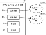
- the optical fiber sensing system includes an optical fiber network (in the figure, appropriately referred to as an optical fiber NW (Network)) 10 and an optical fiber sensing device 20. .. Further, the optical fiber sensing device 20 includes a transmission / reception unit 21, a specific unit 22, and a providing unit 23.
- NW Network
- the optical fiber network 10 is composed of one or more sensing optical fibers 11.
- the sensing optical fiber 11 is laid, for example, in a structure such as a utility pole, a road, a railroad track, the seabed, the ground, indoors (for example, a floor, a ceiling, a wall) or the like.
- the optical fiber network 10 is preferably an existing optical fiber network, but may be a newly installed optical fiber network.
- the transmission / reception unit 21 sends pulsed light to the sensing optical fiber 11 constituting the optical fiber network 10, and uses the backward scattered light generated as the pulsed light is transmitted through the sensing optical fiber 11 as an optical signal. Receive.
- the monitoring targets monitored by the optical fiber sensing system according to the first embodiment are as follows, for example. ⁇ Conditions including deterioration of structures such as electric poles, bridges, tunnels, pipes, dams ⁇ Conditions including deterioration of railroads and roads ⁇ Conditions of railroads and roads ⁇ Behavior of people, vehicles, animals, etc.
- the optical fiber network 10 can detect sensing information including vibration, sound, temperature, and the like related to the monitored object, and the optical fiber network 10 detects the optical signal transmitted through the sensing optical fiber 11. Sensing information will be superimposed.
- the sensing information may include at least one of vibration, sound, and temperature related to the monitored object.
- a plurality of sensing information regarding a plurality of monitoring targets are superimposed on the optical signal transmitted through the sensing optical fiber 11.
- the sensing optical fiber 11 is laid on a utility pole and the sensing information is vibration information
- the optical signal transmitted through the sensing optical fiber 11 includes vibration generated according to the deterioration state of the utility pole and the periphery of the utility pole.
- Sensing information about various monitoring targets such as vibration generated according to the air volume of the light is superimposed.
- the identification unit 22 can identify a plurality of monitoring targets based on a plurality of sensing information regarding the plurality of monitoring targets superimposed on the optical signal transmitted through the sensing optical fiber 11.
- the specifying unit 22 specifies two monitoring targets (hereinafter, referred to as first and second monitoring targets).
- the specific unit 22 extracts the sensing information (hereinafter, referred to as the first sensing information) regarding the first monitoring target from the optical signal received from the optical fiber network 10 by the transmission / reception unit 21, and the extracted first.
- the first monitoring target is specified based on the sensing information of.
- the specific unit 22 extracts the sensing information (hereinafter, referred to as the second sensing information) regarding the second monitoring target from the optical signal received from the optical fiber network 10 by the transmission / reception unit 21, and the extracted second The second monitoring target is specified based on the sensing information.
- the sensing information hereinafter, referred to as the second sensing information
- the specifying unit 22 can specify the position (distance from the optical fiber sensing device 20) on the sensing optical fiber 11 in which the first and second sensing information is detected as follows. ..
- the specific unit 22 determines the time when the transmission / reception unit 21 sends pulsed light to the sensing optical fiber 11 and the time when the transmission / reception unit 21 transmits the sensing optical fiber 11. Based on the time difference from the time when the backward scattered light is received from the light, the position on the sensing optical fiber 11 where the first or second sensing information superimposed on the backward scattered light is detected is specified.
- the specific unit 22 may have information for associating the position on the sensing optical fiber 11 with the actual geographical position. For example, as shown in FIG. 2, the specific unit 22 holds in advance a correspondence table in which the distance from the optical fiber sensing device 20 in the sensing optical fiber 11 and each region or point on the map are associated with each other. You may be. As a result, the specific unit 22 determines which area or point on the map the first or second sensing information is detected, that is, which area on the map the specified first or second monitoring target is. Or it is possible to determine which point it belongs to.
- the providing unit 23 provides the service provider with information regarding the first and second monitoring targets specified by the specific unit 22.
- the number of service providers may be one or a plurality.
- the information regarding the first and second monitoring targets may be provided to the same service provider or may be provided to different service providers.
- the optical fiber sensing device is realized as a platform in the case of realizing the service of providing the information regarding the first and second monitoring targets to the service provider. Become.
- vibration information as sensing information is superimposed on the optical signal received by the transmission / reception unit 21.
- This vibration information includes a unique dynamic fluctuation pattern in which patterns such as vibration intensity, vibration position, and frequency fluctuation transition are different depending on the first monitoring target. Furthermore, this vibration information also includes a unique dynamic fluctuation pattern according to the second monitoring target.
- acoustic information and temperature information as sensing information are also superimposed on the optical signal received by the transmission / reception unit 21. Then, as with the vibration information, these acoustic information and temperature information also have a unique dynamic fluctuation pattern according to the first monitoring target and a unique dynamic fluctuation pattern according to the second monitoring target. Includes.
- the specific unit 22 extracts the first sensing information including the unique dynamic fluctuation pattern according to the first monitoring target from the optical signal received by the transmission / reception unit 21, and analyzes the extracted fluctuation pattern. This makes it possible to identify the first monitoring target.
- the specific unit 22 extracts the second sensing information including the unique dynamic fluctuation pattern according to the second monitoring target from the optical signal received by the transmission / reception unit 21, and analyzes the extracted fluctuation pattern. This makes it possible to identify the second monitoring target.
- the sensing optical fiber 11 is laid on a utility pole (for example, it is overhead-wired on a utility pole).
- the deterioration state of the utility pole, the air volume around the utility pole, and the like can be considered.
- the identification unit 22 is one method of specifying the deterioration state of the utility pole and the air volume around the utility pole by observing the vibration pattern corresponding to these.
- the deterioration state of the utility pole may be specified by the specific unit 22 in detail as follows.
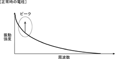
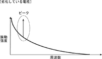
- the identification unit 22 extracts sensing information including a vibration pattern according to the deterioration state of the utility pole as shown in FIGS. 3 and 4 from the optical signal received by the transmission / reception unit 21.
- 3 and 4 show the vibration pattern of the vibration generated in a certain utility pole, and the horizontal axis shows the frequency and the vertical axis shows the vibration intensity.
- the specifying unit 22 can specify the deterioration state of the utility pole based on the frequency at which the peak of the vibration intensity occurs.
- the sensing optical fiber 11 is laid along the road (for example, laid on the side of the road or buried under the road).
- examples of the first and second monitoring targets include road traffic conditions, road surface conditions (for example, freeze-drying, wetness, etc.), tire conditions of vehicles traveling on the road, and road potholes. Occurrence situation etc. can be considered.
- the identification unit 22 is one method of specifying the vibration pattern corresponding to the traffic condition of the road, the tire condition of the vehicle traveling on the road, and the occurrence condition of the pothole on the road. Further, the specific unit 22 is one method of specifying the temperature pattern corresponding to the road surface condition of the road.
- the specific unit 22 may specify in detail as follows.
- the identification unit 22 extracts sensing information including a vibration pattern according to the traffic condition of the road as shown in FIG. 5 from the optical signal received by the transmission / reception unit 21.
- FIG. 5 shows a vibration pattern showing the passage of vibration generated at each position on the road, with the horizontal axis representing the distance from the optical fiber sensing device 20 and the vertical axis representing the time. The vertical axis becomes older data as it goes in the positive direction.
- the fact that one vehicle is traveling on the road is represented by one diagonal line.
- the slope of the line indicates the traveling speed of the vehicle, and the smaller the absolute value of the inclination of the line, the faster the traveling speed.
- the inclination direction of the line indicates the traveling direction of the vehicle, and the change in the inclination of the line indicates that the vehicle has accelerated or decelerated.
- the distance G in the horizontal axis direction of the line represents the distance between vehicles, and the shorter the distance G, the shorter the distance between vehicles.
- the specifying unit 22 can specify the presence or absence of traffic congestion as the traffic condition of the road based on the vibration pattern shown in FIG. Further, the specific unit 22 can specify the number of vehicles traveling on the road, the traveling speed, the presence or absence of dangerous vehicles that repeat acceleration / deceleration, and the like as the traffic condition of the road.
- the identification unit 22 is one method of identifying the occurrence of a natural disaster and the behavior of a person by observing a vibration pattern corresponding to these.
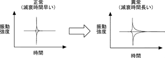
- the specific unit 22 may specify in detail as follows. First, the specific unit 22 extracts sensing information including a vibration pattern according to the occurrence situation of a natural disaster as shown in FIG. 6 from the optical signal received by the transmission / reception unit 21.
- FIG. 6 shows a vibration pattern of vibration generated in the ground, where the horizontal axis represents time and the vertical axis represents vibration intensity.
- the vibration generated in the ground is subsequently attenuated.
- this decay time becomes long. Therefore, the specific unit 22 can detect that the structural change or collapse of the ground may occur based on the decay time.
- the specific unit 22 may specify the first and second monitoring targets by using pattern matching.
- the first sensing information is vibration information
- the specific unit 22 stores in advance a vibration pattern corresponding to the first monitoring target in a storage unit (not shown) as a matching pattern.
- a plurality of vibration patterns according to the deterioration level of the utility pole may be stored.
- the identification unit 22 compares the vibration pattern included in the first sensing information extracted from the optical signal with the matching pattern. When there is a matching pattern in the matching pattern whose matching rate with the vibration pattern is equal to or higher than the threshold value, the specific unit 22 determines that the utility pole has a deterioration level corresponding to the matching pattern.
- the specifying unit 22 may specify the second monitoring target in the same manner as the first monitoring target.
- the specific unit 22 may specify the first and second monitoring targets by using a learning model that specifies the monitoring target by a convolutional neural network (CNN).
- CNN convolutional neural network
- the specific unit 22 inputs a plurality of sets of teacher data indicating the first monitoring target and vibration patterns corresponding to the first monitoring target.
- a learning model for the first monitoring target is constructed in advance and stored in advance in a storage unit (not shown). For example, when the first monitoring target is the deterioration state of the utility pole, a plurality of sets of teacher data indicating the deterioration level of the utility pole and the vibration pattern at the deterioration level are input, and the first monitoring target is You just have to build a learning model for.
- the specific unit 22 inputs the vibration pattern included in the first sensing information extracted from the optical signal into the learning model for the first monitoring target. As a result, the specific unit 22 obtains the deterioration level of the utility pole as the output result of the learning model for the first monitoring target.
- the specifying unit 22 may specify the second monitoring target in the same manner as the first monitoring target.
- the first and second monitoring targets an example of a method of specifying the deterioration state of the utility pole, the traffic condition of the road, etc. has been described, but the above-mentioned method specifies other monitoring targets. The same can be applied to the case.
- the transmission / reception unit 21 receives an optical signal from the optical fiber network 10 (step S101).
- the identification unit 22 identifies the first monitoring target based on the first sensing information regarding the first monitoring target superimposed on the optical signal received by the transmission / reception unit 21 (step S102). Further, the identification unit 22 identifies the second monitoring target based on the second sensing information regarding the second monitoring target superimposed on the optical signal received by the transmission / reception unit 21 (step S103). The order of step S102 and step S103 may be reversed. After that, the providing unit 23 provides the service provider with the information regarding the first monitoring target and the information regarding the second monitoring target specified by the specific unit 22 (step S104).
- the transmission / reception unit 21 receives an optical signal from the optical fiber network 10.
- the identification unit 22 identifies the first monitoring target based on the first sensing information superimposed on the optical signal received by the transmission / reception unit 21, and the second transmission / reception unit 21 superimposes the second on the optical signal received.
- the second monitoring target is specified based on the sensing information.
- the providing unit 23 provides the service provider with information regarding the first monitoring target and information regarding the second monitoring target specified by the specific unit 22.
- the first and second monitoring targets are monitored.
- more advanced optical fiber sensing services and applications such as providing information on a plurality of monitoring targets to service providers by utilizing the sensing optical fibers 11 laid in various locations and states, are realized. be able to.
- the second embodiment is an example in which a plurality of optical fiber networks 10 are provided.
- FIG. 8 shows an example in which two optical fiber networks 10a and 10b exist.
- the optical fiber sensing system according to the second embodiment includes two optical fiber networks 10a and 10b as compared with the first embodiment described above, and two optical fiber networks. The difference is that two transmission / reception units 21a and 21b corresponding to 10a and 10b are provided inside the optical fiber sensing device 20.
- the optical fiber network 10a is composed of one or more sensing optical fibers 11a. Further, the optical fiber network 10b is composed of one or more sensing optical fibers 11b.
- the transmission / reception unit 21a receives an optical signal from the optical fiber network 10a. Further, the transmission / reception unit 21b receives an optical signal from the optical fiber network 10b.
- the identification unit 22 can specify a plurality of monitoring targets. However, in the following, for the sake of simplification of the description, it is assumed that the specifying unit 22 specifies the first and second monitoring targets as in the above-described first embodiment.
- the specific unit 22 relates to the first monitoring target in which the transmission / reception unit 21a is superimposed on either the optical signal received from the optical fiber network 10a or the transmission / reception unit 21b is superimposed on the optical signal received from the optical fiber network 10b.
- the first monitoring target is specified based on the sensing information of 1.
- the specific unit 22 relates to a second monitoring target in which the transmission / reception unit 21a is superimposed on either the optical signal received from the optical fiber network 10a or the transmission / reception unit 21b is superimposed on the optical signal received from the optical fiber network 10b.
- the second monitoring target is specified based on the sensing information of.
- the identification unit 22 may specify both the first and second monitoring targets by using the optical signal from the optical fiber network 10a, or may use the optical signal from the optical fiber network 10b to specify the first and second monitoring targets. Both the first and second monitoring targets may be specified. Further, the identification unit 22 uses one of the optical signals from the optical fiber network 10a and the optical fiber network 10b to identify the first monitoring target, and uses the other optical signal. Then, the second monitoring target may be specified.
- the two optical fiber networks 10a and 10b may be owned by different businesses. Further, the two optical fiber networks 10a and 10b may be owned by different businesses in different industries, or may be owned by different businesses in the same industry.
- the type of business of the business operator may be a telecommunications carrier, an electric power company, a railway company, a road company, or the like.
- the two optical fiber networks 10a and 10b may be owned by different countries, local governments, and organizations (police, fire department, etc.). Further, the two optical fiber networks 10a and 10b may have different geographical locations from each other. For example, the two optical fiber networks 10a and 10b may be arranged in different prefectures. Further, the two optical fiber networks 10a and 10b may be arranged on land and in the ocean, respectively.
- the two optical fiber networks 10a and 10b may have different laying modes of the sensing optical fiber 11 from each other.
- the two optical fiber networks 10a and 10b have different substances, states (for example, buried in the ground, overhead wiring on utility poles, etc.), height, and the like on which the sensing optical fibers 11a and 11b are laid. They may be different from each other.
- the two optical fiber networks 10a and 10b may be a mixture of a public optical fiber network and a private optical fiber network.
- a public optical fiber network is, for example, an optical fiber network in which sensing optical fibers are laid in public infrastructure such as utility poles, roads, and railroad tracks.
- the private optical fiber network is, for example, an optical fiber network in which sensing optical fibers are laid in private infrastructure such as in a building, a shopping mall, a home, or a factory.
- the optical fiber sensing system according to the second embodiment is a basic operation when both the first and second monitoring targets are specified by using the optical signals from the same optical fiber network 10a or 10b.
- the flow is the same as the flow of the first embodiment described above. Therefore, the description of the flow of the basic operation in the optical fiber sensing system according to the second embodiment will be omitted.
- a plurality of optical fiber networks 10a and 10b are provided.
- the identification unit 22 identifies the first monitoring target based on the first sensing information superimposed on either the optical signal from the optical fiber network 10a or the optical signal from the optical fiber network 10b, and identifies the first monitoring target, and the optical fiber network.
- the second monitoring target is specified based on the second sensing information superimposed on either the optical signal from 10a or the optical signal from the optical fiber network 10b.
- the monitoring range for monitoring the first and second monitoring targets is expanded, so that more diverse monitoring targets can be obtained. Can be monitored.
- Other effects are the same as those in the first embodiment described above.
- the number of service providers may be one or more.
- the third embodiment is an example in which the service providing destinations are limited to a plurality of destinations.
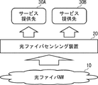
- FIG. 9 shows an example in which two service providers 30A and 30B exist. In the following description, when it is not specified which service provider 30A or 30B is, the service provider 30 is appropriately referred to as the service provider 30.
- the optical fiber sensing system according to the third embodiment has two service providers 30A as service providers for providing information on the monitoring target, as compared with the first embodiment described above.
- 30B is embodied.
- the two service providers 30A and 30B may be, for example, the national government, local governments, companies, individuals, etc., but are not particularly limited.
- the identification unit 22 can specify a plurality of monitoring targets.
- the two service providers 30A and 30B do not need all the information regarding the plurality of monitoring targets that can be specified by the specific unit 22, and the necessary information is the information of the two service providers 30A and 30B. It will vary depending on your needs.
- the optical fiber sensing device 20 is additionally provided with a policy DB (DataBase) 24 as shown in FIG.
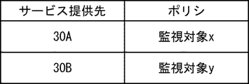
- the policy DB24 is a database that stores policies representing monitoring targets that require information for each of the two service providers 30A and 30B.
- FIG. 11 shows an example of the contents of the policy DB 24 when the specifying unit 22 can specify two, the first monitoring target x and the second monitoring target y.
- the service providing destination 30A needs the information regarding the first monitoring target x, and the service providing destination 30B relates to the second monitoring target y. Determine that you need information.
- the specifying unit 22 identifies the first monitoring target x for which the service providing destination 30A needs information by using the analysis function according to the service providing destination 30A.
- the analysis function according to the service providing destination 30A is a unique dynamic fluctuation pattern (vibration pattern, acoustic pattern, temperature pattern) according to the first monitoring target x for which the service providing destination 30A needs information.
- At least one of) is a function of extracting from an optical signal. That is, the specific unit 22 extracts the first sensing information including the unique dynamic fluctuation pattern according to the first monitoring target x from the optical signal received by the transmission / reception unit 21, and analyzes the extracted fluctuation pattern. By doing so, the first monitoring target x is specified.
- the specifying unit 22 identifies the second monitoring target y for which the service providing destination 30B needs information by using the analysis function according to the service providing destination 30B.
- the method for specifying the second monitoring target y is the same as the method for specifying the first monitoring target x described above.
- the providing unit 23 provides the service providing destination 30A with information regarding the first monitoring target x specified by the specific unit 22 according to the policy stored in the policy DB 24 shown in FIG. 11, and the second unit 22 specifies. Information on the monitoring target y of the above is provided to the service providing destination 30B.
- a specific configuration example of the optical fiber sensing system according to the third embodiment will be described below with reference to FIG.
- a mobility service provider 30C that provides mobility services to the driver of the connected car
- an automobile manufacturer 30D that sells the connected car
- an insurance contract with the driver of the connected car are provided.
- an insurance company 30E to conclude and a road corporation 30F to manage the road.
- the traffic condition of the road In the example of FIG. 12, the traffic condition of the road, the road surface condition of the road, the tire condition of the vehicle traveling on the road, the occurrence condition of the pothole of the road, etc. are monitored.
- Mobility service provider 30C The providing unit 23 provides the mobility service provider 30C with information on the road traffic condition, the road surface condition, the tire condition of the vehicle traveling on the road, the occurrence condition of the road pothole, etc. specified by the specific unit 22. do.
- the mobility service provider 30C is based on the information provided by the providing unit 23 and the location information such as the GPS (Global Positioning System) information of the connected car acquired via the network, and the status and state of each connected car. The following information, customized for, is provided to connected car drivers over the network.
- ⁇ Provide the position of the tail of the traffic jam to prevent traffic accidents ⁇
- Provide the position of the pothole to prevent traffic accidents ⁇ Induce the vehicle speed to slow down
- car tire conditions such as low pressure, flat tires, unbalanced wheel alignment, etc.
- the providing unit 23 provides the automobile manufacturer 30D with the same information as the information provided to the mobility service provider 30C.
- the automobile manufacturer 30D develops a UI (User Interface) for appropriately providing the information provided by the providing unit 23 to the driver of the connected car.
- the automobile manufacturer 30D utilizes the information provided by the providing unit 23 for the development of the driving support function and the development of the automatic driving function.
- the specific unit 22 determines the travel route of the connected car and the traffic accident based on the sensing information extracted from the optical signal and the position information of the connected car acquired via the network. Identify the location of the occurrence. Further, the specific unit 22 determines whether or not the driver of the connected car has acted to prevent a traffic accident according to the above information provided by the mobility service provider 30C. The providing unit 23 provides the determination result of the specific unit 22 to the insurance company 30E.
- the insurance company 30E assesses the compensation amount to be paid to the driver by dynamic rating based on the judgment result of the specific unit 22. In addition, the insurance company 30E determines the driver's insurance premium depending on whether or not the driver is provided with the above information by the mobility service provider 30C.
- the providing unit 23 provides the road corporation 30F with the same information as the information provided to the mobility service provider 30C. Based on the information provided by the provision unit 23, the road corporation 30F guides drivers other than the connected car using an electric bulletin board or the like to maintain an appropriate traffic volume. In addition, the Road Corporation 30F repairs roads based on the information provided by the providing department 23, reduces traffic accidents caused by potholes and the like, and avoids unnecessary proceedings.
- the information supplied from the providing unit 23 to the mobility service provider 30C, the automobile manufacturer 30D, the insurance company 30E, and the road corporation 30F is information related to each other.
- the mobility service provider 30C, the automobile manufacturer 30D, and the insurance company 30E may provide a connected car from the automobile manufacturer 30D to the mobility service provider 30C, or the insurance company 30E may provide insurance to the mobility service provider 30C. You can build business relationships such as providing information.
- the mobility service provider 30C can provide a wide variety of mobility services to the driver of the connected car in cooperation with the automobile manufacturer 30D and the insurance company 30E, so that the service can be diversified and the service quality can be improved. Can be done.
- the specifying unit 22 can specify the first monitoring target x and the second monitoring target y, and the policy DB 24 has the contents of FIG.
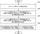
- the transmission / reception unit 21 receives an optical signal from the optical fiber network 10 (step S201).
- the specific unit 22 determines that the service providing destination 30A needs the information regarding the first monitoring target x according to the policy stored in the policy DB 24. Then, the specific unit 22 uses the analysis function according to the service providing destination 30A, and is based on the first sensing information regarding the first monitoring target x superimposed on the optical signal received by the transmission / reception unit 21.
- the monitoring target x of 1 is specified (step S202). Specifically, the specific unit 22 extracts the first sensing information including the unique dynamic fluctuation pattern according to the first monitoring target x from the optical signal received by the transmission / reception unit 21, and the extracted variation. By analyzing the pattern, the first monitoring target x is identified.
- the specifying unit 22 determines that the service providing destination 30B needs information regarding the second monitoring target y according to the policy stored in the policy DB 24. Then, the specific unit 22 uses the analysis function according to the service providing destination 30B, and is based on the second sensing information regarding the second monitoring target y superimposed on the optical signal received by the transmission / reception unit 21.
- the monitoring target y of 2 is specified (step S203). At this time, the specific method for specifying the second monitoring target y is the same as the above-mentioned method for specifying the first monitoring target x. The order of step S202 and step S203 may be reversed.
- the providing unit 23 provides the service providing destination 30A with information regarding the first monitoring target x specified by the specific unit 22 according to the policy stored in the policy DB 24, and the second monitoring target specified by the specific unit 22.
- Information about y is provided to the service provider 30B (step S204).
- the specific unit 22 uses the analysis function according to the service providing destination 30A, and uses the first monitoring target x regarding the first monitoring target x for which the service providing destination 30A needs information.
- the first monitoring target x is specified based on the sensing information of.
- the specifying unit 22 uses the analysis function according to the service providing destination 30B, and based on the second sensing information regarding the second monitoring target y for which the service providing destination 30B needs information, the second monitoring Specify the target y.
- the first monitoring target x for which the service providing destination 30A needs information is specified by using the analysis function according to the service providing destination 30A, and the service is provided.
- the second monitoring target y for which the service providing destination 30B needs information is specified by using the analysis function according to the destination 30B. Therefore, it is possible to improve the accuracy of specifying the first monitoring target x and the second monitoring target y. Other effects are the same as those in the first embodiment described above.
- the specifying unit 22 may notify an alert depending on the specified monitoring target.
- the specific unit 22 displays a GUI (Graphical User Interface) screen on the display unit of the monitoring system that monitors the monitoring target or the terminal possessed by the monitor that monitors the monitoring target, and performs the above notification. Is also good.
- the GUI screen for example, map information indicating the area monitored by the optical fiber network 10, information on the laid optical fiber 11 for sensing, information on the specified monitoring target, and the monitoring target are detected. It can be a screen that visually displays information about the designated area or point. An example of this GUI screen is shown in FIG. FIG.
- the monitoring target displayed on the GUI screen is not limited to the deteriorated part, and can be various targets such as the state and traffic of vehicles and trains, and the behavior of people.
- the transmission / reception units 21, 21a and 21b are provided inside the optical fiber sensing device 20, but the present invention is not limited to this.
- the transmission / reception units 21, 21a, and 21b may be provided outside the optical fiber sensing device 20.
- FIG. 15 shows a configuration example of an optical fiber sensing system in which transmission / reception units 21a and 21b provided inside the optical fiber sensing device 20 according to the second embodiment described above are provided outside the optical fiber sensing device 20. show.
- the optical fiber sensing device 20 is provided with an acquisition unit 25 instead of the transmission / reception units 21a and 21b.
- the acquisition unit 25 is the first sensing regarding the first monitoring target, in which the transmission / reception unit 21a is superimposed on either the optical signal received from the optical fiber network 10a or the transmission / reception unit 21b is superimposed on the optical signal received from the optical fiber network 10b.
- the information and the second sensing information regarding the second monitoring target are acquired.
- the optical fiber sensing device 20 can be arranged at a position away from the optical fiber networks 10a and 10b and the transmission / reception units 21 and 21a and 21b, and may be arranged on the cloud, for example. ..
- FIG. 16 shows a network configuration example of the optical fiber sensing system shown in FIG. 15 when the optical fiber sensing device 20 is arranged on the cloud.
- the transmission / reception unit 21a is connected to the cloud network 43 via the VPN (Virtual Private Network) router 41a and the VPN GW (Gateway) 42
- the transmission / reception unit 21b is connected to the VPN router 41b and It is connected to the cloud network 43 via VPN GW42.
- the optical fiber sensing device 20 is arranged in, for example, a VPC (Virtual Private Cloud) 44 in the cloud network 43.
- VPC Virtual Private Cloud
- the computer 50 includes a processor 501, a memory 502, a storage 503, an input / output interface (input / output I / F) 504, a communication interface (communication I / F) 505, and the like.
- the processor 501, the memory 502, the storage 503, the input / output interface 504, and the communication interface 505 are connected by a data transmission line for transmitting and receiving data to and from each other.
- the processor 501 is, for example, an arithmetic processing unit such as a CPU (Central Processing Unit) or a GPU (Graphics Processing Unit).
- the memory 502 is, for example, a memory such as a RAM (Random Access Memory) or a ROM (Read Only Memory).
- the storage 503 is, for example, a storage device such as an HDD (Hard Disk Drive), an SSD (Solid State Drive), or a memory card. Further, the storage 503 may be a memory such as a RAM or a ROM.
- the storage 503 stores a program that realizes the functions of the components (transmitting / receiving units 21,21a, 21b, specifying unit 22, and providing unit 23) included in the optical fiber sensing device 20. By executing each of these programs, the processor 501 realizes the functions of the components included in the optical fiber sensing device 20.
- the processor 501 may read these programs on the memory 502 and then execute the programs, or may execute the programs without reading them on the memory 502.
- the memory 502 and the storage 503 also play a role of storing information and data held by the components included in the optical fiber sensing device 20.
- Non-temporary computer-readable media include various types of tangible storage media.
- Examples of non-temporary computer-readable media include magnetic recording media (eg, flexible discs, magnetic tapes, hard disk drives), photomagnetic recording media (eg, photomagnetic discs), CD-ROMs (Compact Disc-ROMs), CDs. -R (CD-Recordable), CD-R / W (CD-ReWritable), semiconductor memory (for example, mask ROM, PROM (Programmable ROM), EPROM (Erasable PROM), flash ROM, RAM.
- the program also includes.
- the computer-readable medium can supply the program to the computer via a wired communication path such as an electric wire and an optical fiber, or a wireless communication path.
- the input / output interface 504 is connected to the display device 5041, the input device 5042, the sound output device 5043, and the like.
- the display device 5041 is a device that displays a screen corresponding to drawing data processed by the processor 501, such as an LCD (Liquid Crystal Display), a CRT (Cathode Ray Tube) display, and a monitor.
- the input device 5042 is a device that receives an operator's operation input, and is, for example, a keyboard, a mouse, a touch sensor, and the like.
- the display device 5041 and the input device 5042 may be integrated and realized as a touch panel.
- the sound output device 5043 is a device such as a speaker that acoustically outputs sound corresponding to acoustic data processed by the processor 501.
- the communication interface 505 sends and receives data to and from an external device.
- the communication interface 505 communicates with an external device via a wired communication path or a wireless communication path.
- Appendix 1 An optical fiber network that detects the first sensing information regarding the first monitoring target and the second sensing information regarding the second monitoring target, and A receiver that receives an optical signal from the optical fiber network and The first monitoring target is specified based on the first sensing information superimposed on the optical signal, and the second monitoring target is specified based on the second sensing information superimposed on the optical signal.
- a providing unit that provides the service provider with information on the first monitoring target and information on the second monitoring target specified by the specific unit.
- An optical fiber sensing system An optical fiber sensing system.
- the providing part The information regarding the first monitoring target specified by the specific unit is provided to the first service provider, and the information is provided to the first service provider. Providing information on the second monitoring target specified by the specific unit to the second service provider.
- the optical fiber sensing system according to Appendix 1. The specific part is Using the analysis function according to the first service provider, the first monitoring target is specified based on the first sensing information. Using the analysis function according to the second service provider, the second monitoring target is specified based on the second sensing information.
- the optical fiber sensing system according to Appendix 2. (Appendix 4) The information regarding the first monitoring target provided to the first service providing destination and the information regarding the second monitoring target provided to the second service providing destination are information related to each other.
- the optical fiber sensing system according to Appendix 2 or 3. (Appendix 5) Equipped with a plurality of the above-mentioned optical fiber networks
- the specific part is The first monitoring target is specified based on the first sensing information included in the optical signal from any of the plurality of optical fiber networks.
- the second monitoring target is specified based on the second sensing information included in the optical signal from any of the plurality of optical fiber networks.
- the specific part is The first monitoring target is identified based on the unique dynamic fluctuation pattern according to the first monitoring target included in the first sensing information.
- the second monitoring target is specified based on a unique dynamic fluctuation pattern according to the second monitoring target included in the second sensing information.
- the optical fiber sensing system according to any one of Appendix 1 to 5.
- the first sensing information and the second sensing information include at least one of vibration, sound, and temperature.
- the optical fiber sensing system according to any one of Appendix 1 to 6. This is an optical fiber sensing method using an optical fiber sensing system.
- a receiving step of receiving an optical signal from an optical fiber network that detects a first sensing information regarding a first monitoring target and a second sensing information regarding a second monitoring target, and a receiving step.
- the first monitoring target is specified based on the first sensing information superimposed on the optical signal
- the second monitoring target is specified based on the second sensing information superimposed on the optical signal.
- Fiber optic sensing methods including. (Appendix 9)
- the information regarding the first monitoring target specified in the specific step is provided to the first service provider, and the information is provided to the first service provider.
- the specific step Using the analysis function according to the first service provider, the first monitoring target is specified based on the first sensing information.
- the second monitoring target is specified based on the second sensing information.
- the optical fiber sensing method according to Appendix 9. The information regarding the first monitoring target provided to the first service providing destination and the information regarding the second monitoring target provided to the second service providing destination are information related to each other.
- the optical fiber sensing system is provided with a plurality of the optical fiber networks, and in the specific step, the optical fiber sensing system is provided.
- the first monitoring target is specified based on the first sensing information included in the optical signal from any of the plurality of optical fiber networks.
- the second monitoring target is specified based on the second sensing information included in the optical signal from any of the plurality of optical fiber networks.
- the first monitoring target is identified based on the unique dynamic fluctuation pattern according to the first monitoring target included in the first sensing information.
- the second monitoring target is specified based on a unique dynamic fluctuation pattern according to the second monitoring target included in the second sensing information.
- the optical fiber sensing method according to any one of Appendix 8 to 12.
- the first sensing information and the second sensing information include at least one of vibration, sound, and temperature.
- a receiving unit that receives an optical signal from an optical fiber network that detects a first sensing information regarding a first monitoring target and a second sensing information regarding a second monitoring target.
- the first monitoring target is specified based on the first sensing information superimposed on the optical signal
- the second monitoring target is specified based on the second sensing information superimposed on the optical signal.
- a providing unit that provides the service provider with information on the first monitoring target and information on the second monitoring target specified by the specific unit.
- An optical fiber sensing device (Appendix 16) The providing part The information regarding the first monitoring target specified by the specific unit is provided to the first service provider, and the information is provided to the first service provider. Providing information on the second monitoring target specified by the specific unit to the second service provider.
- the optical fiber sensing device according to Appendix 15.
- the specific part is Using the analysis function according to the first service provider, the first monitoring target is specified based on the first sensing information. Using the analysis function according to the second service provider, the second monitoring target is specified based on the second sensing information.
- the optical fiber sensing device according to Appendix 16. (Appendix 18) The information regarding the first monitoring target provided to the first service providing destination and the information regarding the second monitoring target provided to the second service providing destination are information related to each other.
- a plurality of the above-mentioned optical fiber networks are provided, and The specific part is The first monitoring target is specified based on the first sensing information included in the optical signal from any of the plurality of optical fiber networks.
- the second monitoring target is specified based on the second sensing information included in the optical signal from any of the plurality of optical fiber networks.
- the optical fiber sensing device according to any one of Appendix 15 to 18. The specific part is The first monitoring target is identified based on the unique dynamic fluctuation pattern according to the first monitoring target included in the first sensing information.
- the second monitoring target is specified based on a unique dynamic fluctuation pattern according to the second monitoring target included in the second sensing information.
- the first sensing information and the second sensing information include at least one of vibration, sound, and temperature.
Landscapes
- Physics & Mathematics (AREA)
- General Physics & Mathematics (AREA)
- Alarm Systems (AREA)
- Measurement Of Mechanical Vibrations Or Ultrasonic Waves (AREA)
Priority Applications (3)
| Application Number | Priority Date | Filing Date | Title |
|---|---|---|---|
| US17/908,078 US12352619B2 (en) | 2020-03-06 | 2020-03-06 | Optical fiber sensing system, optical fiber sensing method, and optical fiber sensing apparatus |
| PCT/JP2020/009653 WO2021176683A1 (ja) | 2020-03-06 | 2020-03-06 | 光ファイバセンシングシステム、光ファイバセンシング方法、及び光ファイバセンシング装置 |
| JP2022504910A JP7311023B2 (ja) | 2020-03-06 | 2020-03-06 | 光ファイバセンシングシステム、光ファイバセンシング方法、及び光ファイバセンシング装置 |
Applications Claiming Priority (1)
| Application Number | Priority Date | Filing Date | Title |
|---|---|---|---|
| PCT/JP2020/009653 WO2021176683A1 (ja) | 2020-03-06 | 2020-03-06 | 光ファイバセンシングシステム、光ファイバセンシング方法、及び光ファイバセンシング装置 |
Publications (1)
| Publication Number | Publication Date |
|---|---|
| WO2021176683A1 true WO2021176683A1 (ja) | 2021-09-10 |
Family
ID=77613984
Family Applications (1)
| Application Number | Title | Priority Date | Filing Date |
|---|---|---|---|
| PCT/JP2020/009653 Ceased WO2021176683A1 (ja) | 2020-03-06 | 2020-03-06 | 光ファイバセンシングシステム、光ファイバセンシング方法、及び光ファイバセンシング装置 |
Country Status (3)
| Country | Link |
|---|---|
| US (1) | US12352619B2 (https=) |
| JP (1) | JP7311023B2 (https=) |
| WO (1) | WO2021176683A1 (https=) |
Cited By (1)
| Publication number | Priority date | Publication date | Assignee | Title |
|---|---|---|---|---|
| WO2023079605A1 (ja) * | 2021-11-04 | 2023-05-11 | 日本電気株式会社 | 料金管理システム、料金管理装置及び料金管理方法 |
Families Citing this family (1)
| Publication number | Priority date | Publication date | Assignee | Title |
|---|---|---|---|---|
| US12347311B2 (en) * | 2021-04-09 | 2025-07-01 | Nec Corporation | Road monitoring system, road monitoring device, and road monitoring method |
Citations (3)
| Publication number | Priority date | Publication date | Assignee | Title |
|---|---|---|---|---|
| JP2007198973A (ja) * | 2006-01-27 | 2007-08-09 | Matsushita Electric Works Ltd | フェンス振動センサ装置 |
| JP2013253831A (ja) * | 2012-06-06 | 2013-12-19 | Panasonic Corp | 異常音検知装置及び方法 |
| US20170176243A1 (en) * | 2015-08-14 | 2017-06-22 | Halliburton Energy Services, Inc. | Mud pulse detection using distributed acoustic sensing |
Family Cites Families (2)
| Publication number | Priority date | Publication date | Assignee | Title |
|---|---|---|---|---|
| JP2002269656A (ja) | 2001-03-12 | 2002-09-20 | Foundation Of River & Basin Integrated Communications Japan | 河川情報提供システム |
| WO2018045433A1 (en) * | 2016-09-08 | 2018-03-15 | Mark Andrew Englund | Method and system for distributed acoustic sensing |
-
2020
- 2020-03-06 WO PCT/JP2020/009653 patent/WO2021176683A1/ja not_active Ceased
- 2020-03-06 JP JP2022504910A patent/JP7311023B2/ja active Active
- 2020-03-06 US US17/908,078 patent/US12352619B2/en active Active
Patent Citations (3)
| Publication number | Priority date | Publication date | Assignee | Title |
|---|---|---|---|---|
| JP2007198973A (ja) * | 2006-01-27 | 2007-08-09 | Matsushita Electric Works Ltd | フェンス振動センサ装置 |
| JP2013253831A (ja) * | 2012-06-06 | 2013-12-19 | Panasonic Corp | 異常音検知装置及び方法 |
| US20170176243A1 (en) * | 2015-08-14 | 2017-06-22 | Halliburton Energy Services, Inc. | Mud pulse detection using distributed acoustic sensing |
Cited By (2)
| Publication number | Priority date | Publication date | Assignee | Title |
|---|---|---|---|---|
| WO2023079605A1 (ja) * | 2021-11-04 | 2023-05-11 | 日本電気株式会社 | 料金管理システム、料金管理装置及び料金管理方法 |
| JPWO2023079605A1 (https=) * | 2021-11-04 | 2023-05-11 |
Also Published As
| Publication number | Publication date |
|---|---|
| JPWO2021176683A1 (https=) | 2021-09-10 |
| US12352619B2 (en) | 2025-07-08 |
| US20230112149A1 (en) | 2023-04-13 |
| JP7311023B2 (ja) | 2023-07-19 |
Similar Documents
| Publication | Publication Date | Title |
|---|---|---|
| US12117336B2 (en) | Optical fiber sensing system, optical fiber sensing method, and optical fiber sensing apparatus | |
| JP2023015211A (ja) | 分散音響センシングのための方法およびシステム | |
| Kim et al. | Integrating travel demand modeling and flood hazard risk analysis for evacuation and sheltering | |
| US20130116920A1 (en) | System, method and program product for flood aware travel routing | |
| US12347312B2 (en) | Cooperative vehicle-infrastructure processing method and apparatus, electronic device, and storage medium | |
| JP7158128B2 (ja) | 災害発生可能性算出システム及び方法、プログラム、及び記録媒体 | |
| US10319229B1 (en) | Data mining for alerts regarding road conditions | |
| US10809722B2 (en) | Navigation system with route prediction mechanism and method of operation thereof | |
| JP2012008957A (ja) | 位置特定システム、サーバ装置、端末装置、位置特定方法、および、プログラム | |
| Wang et al. | Modeling travel time reliability of road network considering connected vehicle guidance characteristics indexes | |
| Toma-Danila | A GIS framework for evaluating the implications of urban road network failure due to earthquakes: Bucharest (Romania) case study | |
| Bahaaldin et al. | A Case Study on the Impacts of Connected Vehicle Technology on No‐Notice Evacuation Clearance Time | |
| WO2021176683A1 (ja) | 光ファイバセンシングシステム、光ファイバセンシング方法、及び光ファイバセンシング装置 | |
| KR102441680B1 (ko) | 재난방지용 콘크리트 옹벽블록 운영 관리 시스템 | |
| CN109584536A (zh) | 道路天气事件监控的方法、装置及系统 | |
| Honma et al. | Traffic impacts of on-street parking cars on secondary north-south streets in downtown Yangon | |
| WO2021152787A1 (ja) | 構造物劣化検出システム、構造物劣化検出方法、及び構造物劣化検出装置 | |
| JP7622578B2 (ja) | 地盤沈下エリア特定装置、車両制御装置及び地盤沈下エリア特定システム | |
| Bahaaldin et al. | The impact of traffic incident locations on a metropolitan evacuation | |
| WO2022113164A1 (ja) | 光ファイバセンシングシステム、光ファイバセンシング方法、及び光ファイバセンシング装置 | |
| US20180144260A1 (en) | High-risk road location prediction | |
| JP2023007170A (ja) | 情報処理装置 | |
| JP7265832B1 (ja) | 緊急通行規制判断支援システムおよびプログラム、道路管理方法 | |
| JP7746518B1 (ja) | 道路災害対応支援システムおよびプログラム、道路管理方法 | |
| JP7711299B1 (ja) | 道路災害対応支援システムおよびプログラム、道路管理方法 |
Legal Events
| Date | Code | Title | Description |
|---|---|---|---|
| 121 | Ep: the epo has been informed by wipo that ep was designated in this application |
Ref document number: 20923405 Country of ref document: EP Kind code of ref document: A1 |
|
| ENP | Entry into the national phase |
Ref document number: 2022504910 Country of ref document: JP Kind code of ref document: A |
|
| NENP | Non-entry into the national phase |
Ref country code: DE |
|
| 122 | Ep: pct application non-entry in european phase |
Ref document number: 20923405 Country of ref document: EP Kind code of ref document: A1 |
|
| WWG | Wipo information: grant in national office |
Ref document number: 17908078 Country of ref document: US |