WO2021166825A1 - Data management system, management method, and management program - Google Patents
Data management system, management method, and management program Download PDFInfo
- Publication number
- WO2021166825A1 WO2021166825A1 PCT/JP2021/005420 JP2021005420W WO2021166825A1 WO 2021166825 A1 WO2021166825 A1 WO 2021166825A1 JP 2021005420 W JP2021005420 W JP 2021005420W WO 2021166825 A1 WO2021166825 A1 WO 2021166825A1
- Authority
- WO
- WIPO (PCT)
- Prior art keywords
- comparison
- management
- location
- adjacent
- identification information
- Prior art date
Links
Images


Classifications
-
- G—PHYSICS
- G06—COMPUTING; CALCULATING OR COUNTING
- G06F—ELECTRIC DIGITAL DATA PROCESSING
- G06F16/00—Information retrieval; Database structures therefor; File system structures therefor
- G06F16/20—Information retrieval; Database structures therefor; File system structures therefor of structured data, e.g. relational data
- G06F16/21—Design, administration or maintenance of databases
- G06F16/211—Schema design and management
- G06F16/212—Schema design and management with details for data modelling support
-
- G—PHYSICS
- G06—COMPUTING; CALCULATING OR COUNTING
- G06F—ELECTRIC DIGITAL DATA PROCESSING
- G06F30/00—Computer-aided design [CAD]
- G06F30/10—Geometric CAD
- G06F30/13—Architectural design, e.g. computer-aided architectural design [CAAD] related to design of buildings, bridges, landscapes, production plants or roads
-
- G—PHYSICS
- G06—COMPUTING; CALCULATING OR COUNTING
- G06F—ELECTRIC DIGITAL DATA PROCESSING
- G06F30/00—Computer-aided design [CAD]
- G06F30/20—Design optimisation, verification or simulation
-
- Y—GENERAL TAGGING OF NEW TECHNOLOGICAL DEVELOPMENTS; GENERAL TAGGING OF CROSS-SECTIONAL TECHNOLOGIES SPANNING OVER SEVERAL SECTIONS OF THE IPC; TECHNICAL SUBJECTS COVERED BY FORMER USPC CROSS-REFERENCE ART COLLECTIONS [XRACs] AND DIGESTS
- Y02—TECHNOLOGIES OR APPLICATIONS FOR MITIGATION OR ADAPTATION AGAINST CLIMATE CHANGE
- Y02P—CLIMATE CHANGE MITIGATION TECHNOLOGIES IN THE PRODUCTION OR PROCESSING OF GOODS
- Y02P90/00—Enabling technologies with a potential contribution to greenhouse gas [GHG] emissions mitigation
- Y02P90/30—Computing systems specially adapted for manufacturing
Definitions
- the comparison points are as designed, and the identification information of the adjacent points, the identification information of the comparison points, the coordinates of the comparison points, and the like. It is also preferable to have a step of storing the shape of the comparison location in the comparison result database with the attribute of the comparison location as "no problem".
- a boundary model of the comparison location is created, the identification information of the adjacent location, the identification information of the comparison location, the comparison location coordinates based on the boundary model, the comparison location shape, and the attributes of the comparison location. It is also preferable to have a step of storing "no problem" in the comparison result database.
- (AB) a step of selecting any of interference, divergence, or no problem from the attribute
- (AC) an adjacent portion having the attribute selected in the (AB) step from the comparison result database. It is also preferable to have a step of selecting, and (AD) a step of referring to the comparison result database for the adjacent portion selected in the (AC) step and confirming the member stored in the adjacent portion.
- the measurement data is further reflected in the measurement database that stores the measurement data related to the building, the measurement data selection unit that selects the measurement data of the management member from the measurement database, and the design model of the management member.
- the current model creation unit that creates the current model of the management member, the boundary information selection unit that selects one adjacent location of the management member by referring to the comparison result database, and the comparison of the adjacent location.
- the adjacent location comparison unit that compares the adjacent location shape stored in the result database with the shape of the current model is provided, and the boundary information creation unit includes the adjacent location shape and the current model shape at the adjacent location.
- the identification information of the adjacent location, the identification information of the comparison location, the coordinates of the comparison location, and the shape of the comparison location are compared with the attribute of the comparison location as "interference". It is stored in the result database, and if there is space, the identification information of the adjacent location, the identification information of the comparison location, the coordinates of the comparison location, and the shape of the comparison location are stored in the comparison result database with the attributes of the comparison location as "difference". If it is stored and there is no interference or space, the identification information of the adjacent location, the identification information of the comparison location, the comparison location coordinates, and the comparison location shape are stored in the comparison result database with the attributes of the comparison location set to "no problem". It is also preferable to memorize.
- the measurement data is reflected in the measurement database that stores the measurement data related to the building, the measurement data selection unit that selects the measurement data of the management member from the measurement database, and the design model of the management member.
- the current model creation unit that creates the current model of the management member
- the boundary information selection unit that selects one adjacent portion of the management member by referring to the comparison result database, and the comparison result database.
- a boundary surface creation unit that creates a boundary surface model of the adjacent portion, an adjacent location comparison unit that compares the boundary surface model and the current model, and an interference portion if there is interference between the boundary surface model and the current model.
- the manager is made to select a confirmation member to be confirmed from the building members in the design database, select an adjacent portion having member identification information of the confirmation member, and relate the selected adjacent portion. It is also preferable to include a related member confirmation unit for confirming the member.
- the management location / member confirmation unit which allows the administrator to select the attribute, select an adjacent portion having the selected attribute, and confirm the member stored in the selected adjacent portion. Is also preferable.
- the input / output device 2 is a general-purpose personal computer, tablet terminal, or the like having at least a calculation unit, a storage unit, a communication unit, a display unit, and an operation unit, and can be operated by an administrator.
- FIG. 6 is a block diagram of a management system 1 ′ according to a second embodiment of the present invention.
- the same components as those in the first embodiment will be omitted from the description using the same reference numerals.
- the management system 1' contains the input / output device 2, the design database 3, the measurement database 4, the management member selection unit 5, the measurement data selection unit 8, the current model creation unit 9, the boundary information selection unit 10, and the boundary information selection unit 10.
- An adjacent location comparison unit 11, a boundary information creation unit 7, and a comparison result database 20 are provided.
- step S2011 the boundary information creation unit 7 asks whether the comparison work is completed for all the adjacent parts of the management member. If the administrator wants to continue the comparison at other adjacent points, the process returns to step S2004, and if the administrator stops the comparison at all the adjacent points, the flow ends.
- the management method and management system of this embodiment after reflecting the measurement data in the design model, it is verified whether or not the members interfere with each other at the adjacent points based on the boundary information managed in advance. Can be done. Further, when the members are separated from each other in the adjacent portion, it is possible to manage as data that there is a dissociation in the adjacent portion. Further, the position of interference and the position of dissociation can be clarified up to the coordinates and stored in the comparison result database 20.
- step S3007 the boundary information creation unit 7 determines whether there is interference or space between the boundary surface model and the current model, and determines the attributes of the comparison points.
- the boundary surface model is a plane, but the current model is a convex surface at the comparison location (coordinates) (see S3007-1 in FIG. 15), it is assumed that there is interference at the comparison location, and step S3008 is performed. Transition.
- the current model is concave at the compared points (coordinates) (see S3007-2 in FIG. 15), it is assumed that there is space at the compared points, and the process proceeds to step S3009.
- the boundary model creation unit 13 When moving to step S3009, the boundary model creation unit 13 creates a model of the spatial portion at this comparison point, that is, a boundary model of the divergent portion (see S3009 in FIG. 15).
- the boundary information creation unit 7 stores the comparison location ID, the adjacent location ID, the comparison location coordinates based on the boundary model, the comparison location shape, and the comparison location attribute "dissociation" in the comparison location table 203, and steps. Move to S3011.
- FIG. 17 is a flow chart showing a method of managing related members according to the fourth embodiment of the present invention.
- the process proceeds to step S4001 and the related member confirmation unit 14 asks for the member. Therefore, the administrator selects the “confirmation member” to be confirmed from the design database 3.
- the related member confirmation unit 14 reads the related member table 202 from the comparison result database 20, picks up the adjacent portion having the member ID of the confirmation member, and wants to confirm with the administrator the adjacent portion. Let me select.
- step S4003 the related member confirmation unit 14 reads out the related member associated with the adjacent portion ID from the related member table 202. As a result, the manager can confirm the related member of the confirmation member.
- step S5111 the administrator has conventionally manually selected the member whose presence or absence of interference is to be confirmed from the design database in step S5111. select.
- step S5112 the administrator proceeds to step S5112 and checks whether all the members to be confirmed have been selected. If there are any items that have not been selected, the process returns to step S5111, and if all items have been selected, the process proceeds to step S5113. Proceeding to step S5113, the arithmetic unit having the check program calculates the interference of the selected member.
- the administrator since the "interference member" is already linked and managed by the comparison point table 203 and the related member table 202, the administrator immediately selects and confirms the interference member based on the attribute data of "interference". can do.
- FIG. 25 is a confirmation flow diagram showing a method of managing a dissociated member according to a fifth embodiment of the present invention.
- the management system and management method according to the present embodiment show another example of utilizing the data of the comparison result database 20 (related member table 202 and comparison location table 203) created in the second or third embodiment.
- the configuration and method that enable data confirmation by combining other classification information of members are shown.
- the same components as those of the above-described embodiments will be omitted from the description by using the same reference numerals. Further, the following will be described by taking the comparison location table 203 created in the second embodiment as an example, but the same applies to the comparison location table 203 created in the third embodiment.
- the management method and the management system of this embodiment it is possible to confirm the state of the adjacent portion between the members by combining other classification information of the members such as the member type.
- the other classification information is not intended to be limited to the member type, and is applied as long as it is some classification information related to the member such as material information of the refractory member or the like.
Abstract
The present invention performs data management/data utilization of information about a boundary between members. This management system comprises: a design database (3) that stores member identification information, member coordinates, and member shapes for building members constituting a building; a management member selection unit (5) that selects a management member to be managed, from among the building members stored in the design database; a related member selection unit (6) that selects, from the design database, a related member which is adjacent to the management member; a boundary information creation unit (7) that selects an adjacency location at which the management member and the related member are adjacent, and associates, as boundary information regarding the adjacency location, identification information of the adjacency location, the adjacency location coordinates, the adjacency location shape, member identification information for the management member, and member identification information for the related member; and a comparison results database (20) that stores information associated by the boundary information creation unit.
Description
本発明は、建築物の設計および施工に関するデータを管理するためのシステム,方法,およびプログラムに関する。
The present invention relates to a system, method, and program for managing data related to building design and construction.
近年、建築の分野では、BIM(Building Information Modeling)と呼ばれる3Dモデルの活用が進んでいる。BIMは、設計現場、すなわち、企画,意匠設計,設備設計,設計分析,実施設計,施工計画,および部品製作において活用が進んでいる。例えば特許文献1には、工場での部材製作の場面でBIMを活用する技術が開示されている。
In recent years, in the field of architecture, the use of 3D models called BIM (Building Information Modeling) has been progressing. BIM is being utilized at design sites, that is, in planning, design design, equipment design, design analysis, implementation design, construction planning, and parts manufacturing. For example, Patent Document 1 discloses a technique for utilizing BIM in the scene of manufacturing a member in a factory.
しかしながら、施工状況の計測結果を設計BIMに反映させた場合、部材同士が重なっているかどうかのチェックは可能であるが、部材のどの場所が干渉しているかの情報はBIMに記憶することができなかった。特に、部材同士が離れているかどうかのチェックは行うことができず、部材の乖離の情報を管理することはできなかった。
However, when the measurement result of the construction status is reflected in the design BIM, it is possible to check whether the members overlap each other, but the information on which part of the member is interfering can be stored in the BIM. There wasn't. In particular, it was not possible to check whether or not the members were separated from each other, and it was not possible to manage information on the dissociation of the members.
本発明は、このような問題点に鑑みてなされたものであり、部材同士の境界情報をデータ管理することを目的とする。
The present invention has been made in view of such problems, and an object of the present invention is to manage boundary information between members as data.
上記課題を解決するために、本発明のある態様の管理方法は、建築物を構成する建築部材について部材識別情報と部材座標と部材形状を記憶した設計データベースと情報の送受信を行って、(A)前記設計データベースに記憶された前記建築部材のなかから、管理対象となる管理部材を選択するステップと、(B)前記設計データベースから、前記管理部材に隣接する関連部材を選択するステップと、(C)前記管理部材と前記関連部材の隣接箇所を選択するステップと、(D)前記隣接箇所について、境界情報として、該隣接箇所の識別情報と,隣接箇所座標と,隣接箇所形状と,前記管理部材の部材識別情報と,前記関連部材の部材識別情報とを関連付けて、比較結果データベースに記憶するステップと、を有することを特徴とする。
In order to solve the above problem, the management method of a certain aspect of the present invention transmits / receives member identification information, member coordinates, and member shape to a design database for building members constituting the building, and (A). ) A step of selecting a management member to be managed from the building members stored in the design database, and (B) a step of selecting a related member adjacent to the management member from the design database. C) A step of selecting an adjacent portion between the management member and the related member, and (D) regarding the adjacent portion, as boundary information, the identification information of the adjacent portion, the coordinates of the adjacent portion, the shape of the adjacent portion, and the management thereof. It is characterized by having a step of associating the member identification information of the member with the member identification information of the related member and storing the member identification information in the comparison result database.
上記態様において、さらに、前記管理部材に関する全ての関連部材について前記境界情報を作成したかを確認し、全て作成していない場合は未作成の関連部材について前記(B)から(D)のステップを行うのも好ましい。
In the above aspect, it is further confirmed whether or not the boundary information has been created for all the related members related to the management member, and if not all the related members have not been created, the steps (B) to (D) are performed for the uncreated related members. It is also preferable to do so.
上記態様において、前記建築物に関する計測データを記憶した計測データベースと、と情報の送受信を行って、(E)前記計測データベースから前記管理部材の計測データを選択するステップと、(F)前記管理部材の設計モデルに前記計測データを反映させた前記管理部材の現状モデルを作成するステップと、(G)前記比較結果データベースを参照し、前記管理部材の隣接箇所を一つ選択するステップと、(H)前記隣接箇所について、前記比較結果データベースに記憶された隣接箇所形状と、前記現状モデルの形状とを比較するステップと、(I)前記隣接箇所において、前記隣接箇所形状と前記現状モデルの形状に干渉または空間があるか判断するステップと、(J)前記(I)ステップにおいて干渉がある場合、比較した比較箇所で干渉ありとして、前記隣接箇所の識別情報と,前記比較箇所の識別情報と,比較箇所座標と,比較箇所形状とを,前記比較箇所の属性を「干渉」として、前記比較結果データベースに記憶するステップと、を有するのも好ましい。
In the above aspect, a step of transmitting and receiving information to and from a measurement database storing measurement data related to the building, (E) selecting measurement data of the management member from the measurement database, and (F) the management member. A step of creating a current model of the management member in which the measurement data is reflected in the design model of the above, and (G) a step of referring to the comparison result database and selecting one adjacent portion of the management member, and (H). ) For the adjacent portion, a step of comparing the adjacent portion shape stored in the comparison result database with the shape of the current model, and (I) in the adjacent portion, the shape of the adjacent portion and the shape of the current model When there is interference in the step of determining whether there is interference or space, and (J) in the step (I), it is considered that there is interference in the compared comparison points, and the identification information of the adjacent points and the identification information of the comparison points are determined. It is also preferable to have a step of storing the comparison location coordinates and the comparison location shape in the comparison result database with the attribute of the comparison location as "interference".
上記態様において、(K)前記(I)ステップにおいて空間がある場合、比較した比較箇所で乖離ありとして、前記隣接箇所の識別情報と,前記比較箇所の識別情報と,比較箇所座標と,比較箇所形状とを,前記比較箇所の属性を「乖離」として、前記比較結果データベースに記憶するステップと、を有するのも好ましい。
In the above aspect, when there is a space in (K) step (I), it is considered that there is a divergence in the compared comparison points, and the identification information of the adjacent points, the identification information of the comparison points, the coordinates of the comparison points, and the comparison points. It is also preferable to have a step of storing the shape in the comparison result database with the attribute of the comparison location as "deviation".
上記態様において、(L)前記(I)ステップにおいて干渉も空間も無い場合、比較した比較箇所は設計通りとして、前記隣接箇所の識別情報と,前記比較箇所の識別情報と,比較箇所座標と,比較箇所形状とを,前記比較箇所の属性を「問題なし」として、前記比較結果データベースに記憶するステップと、を有するのも好ましい。
In the above embodiment, when (L) there is no interference or space in the step (I), the comparison points are as designed, and the identification information of the adjacent points, the identification information of the comparison points, the coordinates of the comparison points, and the like. It is also preferable to have a step of storing the shape of the comparison location in the comparison result database with the attribute of the comparison location as "no problem".
上記態様において、さらに、前記管理部材に関する全ての隣接箇所について比較を終了したかを確認し、他の隣接箇所での比較を続ける場合は、他の隣接箇所について前記(G)から(L)のステップを行うのも好ましい。
In the above aspect, when it is further confirmed whether the comparison has been completed for all the adjacent points related to the control member and the comparison at the other adjacent points is continued, the other adjacent points are described in (G) to (L). It is also preferable to perform steps.
上記態様において、前記建築物に関する計測データを記憶した計測データベースと、と情報の送受信を行って、(M)前記計測データベースから前記管理部材の計測データを選択するステップと、(N)前記管理部材の設計モデルに前記計測データを反映させた前記管理部材の現状モデルを作成するステップと、(O)前記比較結果データベースを参照し、前記管理部材の隣接箇所を一つ選択するステップと、(P)前記隣接箇所について、前記比較結果データベースを参照して境界面モデルを作成するステップと、(Q)前記隣接箇所について、前記境界面モデルと前記現状モデルを比較するステップと、(R)前記隣接箇所において、前記境界面モデルと前記現状モデルに干渉または空間があるか判断するステップと、(S)前記(R)ステップにおいて干渉がある場合、比較箇所で干渉ありとして、干渉部分の境界モデルを作成し、前記隣接箇所の識別情報と,前記比較箇所の識別情報と,前記境界モデルに基づく比較箇所座標,比較箇所形状と,前記比較箇所の属性「干渉」を、前記比較結果データベースに記憶するステップと、(T)前記(R)ステップにおいて空間がある場合、比較箇所で乖離ありとして、乖離部分の境界モデルを作成し、前記隣接箇所の識別情報と,前記比較箇所の識別情報と,前記境界モデルに基づく比較箇所座標,比較箇所形状と,前記比較箇所の属性「乖離」を、前記比較結果データベースに記憶するステップと、(U)前記(R)ステップにおいて干渉も空間も無い場合、比較箇所は設計通りとして、比較箇所の境界モデルを作成し、前記隣接箇所の識別情報と,前記比較箇所の識別情報と,前記境界モデルに基づく比較箇所座標,比較箇所形状と,前記比較箇所の属性「問題なし」を、前記比較結果データベースに記憶するステップと、を有するのも好ましい。
In the above aspect, a step of transmitting and receiving information to and from a measurement database storing measurement data related to the building, (M) selecting measurement data of the management member from the measurement database, and (N) the management member. A step of creating a current model of the management member in which the measurement data is reflected in the design model of the above, and (O) a step of referring to the comparison result database and selecting one adjacent portion of the management member, and (P). ) For the adjacent location, a step of creating a boundary surface model with reference to the comparison result database, (Q) for the adjacent location, a step of comparing the boundary surface model and the current model, and (R) the adjacent portion. If there is interference in the step of determining whether there is interference or space between the boundary surface model and the current model at the location, and (S) the step (R), the boundary model of the interference portion is regarded as having interference at the comparison location. Create and store the identification information of the adjacent portion, the identification information of the comparison location, the comparison location coordinates based on the boundary model, the comparison location shape, and the attribute "interference" of the comparison location in the comparison result database. When there is a space between the step and (T) the step (R), it is assumed that there is a divergence at the comparison point, a boundary model of the divergence part is created, the identification information of the adjacent part, the identification information of the comparison part, and the above. Comparison between the step of storing the comparison location coordinates and comparison location shape based on the boundary model and the attribute "deviation" of the comparison location in the comparison result database, and (U) when there is no interference or space in the (R) step. As the location is as designed, a boundary model of the comparison location is created, the identification information of the adjacent location, the identification information of the comparison location, the comparison location coordinates based on the boundary model, the comparison location shape, and the attributes of the comparison location. It is also preferable to have a step of storing "no problem" in the comparison result database.
上記態様において、(V)前記設計データベースに記憶された前記建築部材のなかから、確認対象となる確認部材を選択するステップと、(W)前記比較結果データベースから前記(V)ステップで選択された確認部材の部材識別情報を有する隣接箇所を選択するステップと、(X)前記比較結果データベースから前記(W)ステップで選択された隣接箇所の関連部材を確認するステップと、を有するのも好ましい。
In the above aspect, (V) a step of selecting a confirmation member to be confirmed from the building members stored in the design database, and (W) a step of selecting from the comparison result database in the (V) step. It is also preferable to have a step of selecting an adjacent portion having member identification information of the confirmation member, and (X) a step of confirming the related member of the adjacent portion selected in the step (W) from the comparison result database.
上記態様において、(Y)前記属性から、干渉,乖離,または問題なしのいずれかを選択するステップと、(Z)前記比較結果データベースから前記(Y)ステップで選択された属性を有する隣接箇所を選択するステップと、(AA)前記(Z)ステップで選択された隣接箇所を確認するステップと、を有するのも好ましい。
In the above aspect, (Y) a step of selecting any of interference, divergence, or no problem from the attributes, and (Z) an adjacent portion having the attribute selected in the (Y) step from the comparison result database. It is also preferable to have a step of selecting and (AA) a step of confirming the adjacent portion selected in the step (Z).
上記態様において、(AB)前記属性から、干渉,乖離,または問題なしのいずれかを選択するステップと、(AC)前記比較結果データベースから前記(AB)ステップで選択された属性を有する隣接箇所を選択するステップと、(AD)前記(AC)ステップで選択された隣接箇所について前記比較結果データベースを参照し、該隣接箇所に記憶されている部材を確認するステップと、を有するのも好ましい。
In the above aspect, (AB) a step of selecting any of interference, divergence, or no problem from the attribute, and (AC) an adjacent portion having the attribute selected in the (AB) step from the comparison result database. It is also preferable to have a step of selecting, and (AD) a step of referring to the comparison result database for the adjacent portion selected in the (AC) step and confirming the member stored in the adjacent portion.
上記態様において、さらに前記設計データベースに前記建築部材に関する他の分類情報を備え、(AE)前記属性から、干渉,乖離,または問題なしのいずれかを選択するステップと、(AF)前記比較結果データベースから前記(AE)ステップで選択された属性を有する隣接箇所を選択するステップと、(AG)前記設計データベースを参照し、前記(AF)ステップで選択された隣接箇所を前記他の分類情報で絞り込むステップと、(AH)前記(AG)ステップで絞り込まれた隣接箇所について前記比較結果データベースを参照し、該隣接箇所に記憶されている部材を確認するステップと、を有するのも好ましい。
In the above aspect, the design database is further provided with other classification information about the building member, (AE) a step of selecting either interference, divergence, or no problem from the attributes, and (AF) the comparison result database. With reference to the step of selecting the adjacent portion having the attribute selected in the (AE) step and (AG) the design database, the adjacent portion selected in the (AF) step is narrowed down by the other classification information. It is also preferable to have (AH) a step of referring to the comparison result database for the adjacent portion narrowed down in the (AG) step and confirming the member stored in the adjacent portion.
上記態様の管理方法を、コンピュータプログラムで記載し、それを実行可能にする管理プログラムも好ましい。
A management program in which the management method of the above aspect is described by a computer program and can be executed is also preferable.
また、上記課題を解決するために、本発明のある態様の管理システムは、建築物を構成する建築部材について部材識別情報と部材座標と部材形状を記憶した設計データベースと、前記設計データベースに記憶された前記建築部材のなかから、管理対象となる管理部材を選択する管理部材選択部と、前記設計データベースから、前記管理部材に隣接する関連部材を選択する関連部材選択部と、前記管理部材と前記関連部材の隣接箇所を選択し、前記隣接箇所について、境界情報として、該隣接箇所の識別情報と,隣接箇所座標と,隣接箇所形状と,前記管理部材の部材識別情報と,前記関連部材の部材識別情報とを関連付ける境界情報作成部と、前記境界情報作成部が関連付けた情報を記憶する比較結果データベースと、を備えることを特徴とする。
Further, in order to solve the above problems, the management system of a certain aspect of the present invention is stored in the design database that stores the member identification information, the member coordinates, and the member shape of the building members constituting the building, and the design database. A management member selection unit that selects a management member to be managed from among the building members, a related member selection unit that selects a related member adjacent to the management member from the design database, the management member, and the above. Adjacent points of the related members are selected, and for the adjacent points, the identification information of the adjacent points, the coordinates of the adjacent points, the shape of the adjacent points, the member identification information of the management member, and the members of the related members are used as boundary information. It is characterized by including a boundary information creating unit that associates with identification information and a comparison result database that stores the information associated with the boundary information creating unit.
上記態様において、さらに、前記建築物に関する計測データを記憶した計測データベースと、前記計測データベースから前記管理部材の計測データを選択する計測データ選択部と、前記管理部材の設計モデルに前記計測データを反映させた、前記管理部材の現状モデルを作成する現状モデル作成部と、前記比較結果データベースを参照し、前記管理部材の隣接箇所を一つ選択する境界情報選択部と、前記隣接箇所について、前記比較結果データベースに記憶された隣接箇所形状と、前記現状モデルの形状とを比較する隣接箇所比較部と、を備え、前記境界情報作成部は、前記隣接箇所において前記隣接箇所形状と前記現状モデルの形状に干渉または空間があるか判断し、干渉がある場合は、前記隣接箇所の識別情報と比較箇所の識別情報と比較箇所座標と比較箇所形状とを前記比較箇所の属性を「干渉」として前記比較結果データベースに記憶し、空間がある場合は、前記隣接箇所の識別情報と前記比較箇所の識別情報と比較箇所座標と比較箇所形状とを前記比較箇所の属性を「乖離」として前記比較結果データベースに記憶し、干渉も空間も無い場合は、前記隣接箇所の識別情報と前記比較箇所の識別情報と比較箇所座標と比較箇所形状とを前記比較箇所の属性を「問題なし」として前記比較結果データベースに記憶するのも好ましい。
In the above aspect, the measurement data is further reflected in the measurement database that stores the measurement data related to the building, the measurement data selection unit that selects the measurement data of the management member from the measurement database, and the design model of the management member. The current model creation unit that creates the current model of the management member, the boundary information selection unit that selects one adjacent location of the management member by referring to the comparison result database, and the comparison of the adjacent location. The adjacent location comparison unit that compares the adjacent location shape stored in the result database with the shape of the current model is provided, and the boundary information creation unit includes the adjacent location shape and the current model shape at the adjacent location. If there is interference or space in the database, and if there is interference, the identification information of the adjacent location, the identification information of the comparison location, the coordinates of the comparison location, and the shape of the comparison location are compared with the attribute of the comparison location as "interference". It is stored in the result database, and if there is space, the identification information of the adjacent location, the identification information of the comparison location, the coordinates of the comparison location, and the shape of the comparison location are stored in the comparison result database with the attributes of the comparison location as "difference". If it is stored and there is no interference or space, the identification information of the adjacent location, the identification information of the comparison location, the comparison location coordinates, and the comparison location shape are stored in the comparison result database with the attributes of the comparison location set to "no problem". It is also preferable to memorize.
上記態様において、前記建築物に関する計測データを記憶した計測データベースと、前記計測データベースから前記管理部材の計測データを選択する計測データ選択部と、前記管理部材の設計モデルに前記計測データを反映させた、前記管理部材の現状モデルを作成する現状モデル作成部と、前記比較結果データベースを参照し、前記管理部材の隣接箇所を一つ選択する境界情報選択部と、前記比較結果データベースを参照して、前記隣接箇所の境界面モデルを作成する境界面作成部と、前記境界面モデルと前記現状モデルを比較する隣接箇所比較部と、前記境界面モデルと前記現状モデルに干渉がある場合は干渉部分の境界モデルを作成し、前記境界面モデルと前記現状モデルに空間がある場合は空間部分の境界モデルを作成し、前記境界面モデルと前記現状モデルに干渉も空間も無い場合は比較箇所の境界モデルを作成する境界モデル作成部と、を備え、前記境界情報作成部は、比較箇所の識別情報と,前記境界モデルに基づく比較箇所座標,比較箇所形状と,前記比較箇所の属性「干渉」または「乖離」または「問題なし」を、前記比較結果データベースに記憶するのも好ましい。
In the above aspect, the measurement data is reflected in the measurement database that stores the measurement data related to the building, the measurement data selection unit that selects the measurement data of the management member from the measurement database, and the design model of the management member. Refer to the current model creation unit that creates the current model of the management member, the boundary information selection unit that selects one adjacent portion of the management member by referring to the comparison result database, and the comparison result database. A boundary surface creation unit that creates a boundary surface model of the adjacent portion, an adjacent location comparison unit that compares the boundary surface model and the current model, and an interference portion if there is interference between the boundary surface model and the current model. Create a boundary model, create a boundary model of the space part when there is space between the boundary surface model and the current model, and create a boundary model of the comparison point when there is no interference or space between the boundary surface model and the current model. The boundary model creation unit is provided with a boundary model creation unit for creating the boundary model, and the boundary information creation unit includes identification information of the comparison location, comparison location coordinates based on the boundary model, comparison location shape, and the attribute "interference" or "interference" of the comparison location. It is also preferable to store "dissociation" or "no problem" in the comparison result database.
上記態様において、管理者に、前記設計データベースの前記建築部材のなかから確認対象となる確認部材を選択させ、前記確認部材の部材識別情報を有する隣接箇所を選択させ、選択された隣接箇所の関連部材を確認させる関連部材確認部、を備えるのも好ましい。
In the above aspect, the manager is made to select a confirmation member to be confirmed from the building members in the design database, select an adjacent portion having member identification information of the confirmation member, and relate the selected adjacent portion. It is also preferable to include a related member confirmation unit for confirming the member.
上記態様において、管理者に、前記属性の選択と、選択された属性を有する隣接箇所の選択をさせ、選択された隣接箇所を確認させる管理箇所・部材確認部、を備えるのも好ましい。
In the above aspect, it is also preferable to include a management location / member confirmation unit that allows the administrator to select the attribute, select an adjacent location having the selected attribute, and confirm the selected adjacent location.
上記態様において、管理者に、前記属性の選択と、選択された属性を有する隣接箇所の選択をさせ、選択された隣接箇所に記憶されている部材を確認させる管理箇所・部材確認部、を備えるのも好ましい。
In the above aspect, the management location / member confirmation unit is provided, which allows the administrator to select the attribute, select an adjacent portion having the selected attribute, and confirm the member stored in the selected adjacent portion. Is also preferable.
上記態様において、前記設計データベースは前記建築部材に関する他の分類情報を備え、さらに、管理者に、前記属性の選択と、選択された属性を有する隣接箇所の選択をさせ、選択された隣接箇所を前記他の分類情報で絞り込み、絞り込まれた隣接箇所に記憶されている部材を確認させる管理箇所・部材確認部、を備えるのも好ましい。
In the above aspect, the design database includes other classification information about the building member, and further causes the manager to select the attribute and select an adjacent portion having the selected attribute, and select the selected adjacent portion. It is also preferable to include a management location / member confirmation unit that narrows down by the other classification information and confirms the members stored in the narrowed-down adjacent locations.
本発明のデータ管理システム,管理方法,管理プログラムによれば、部材同士の境界情報をデータ管理することができる。
According to the data management system, management method, and management program of the present invention, boundary information between members can be managed as data.
次に、本発明の好適な実施の形態について、図面を参照して説明する。
Next, a preferred embodiment of the present invention will be described with reference to the drawings.
<第一の実施形態>
(第一の実施形態に係る管理システムの構成)
図1は、本発明の第一の実施形態に係る管理システム1の構成ブロック図である。管理システム1は、入出力装置2と、設計データベース3と、管理部材選択部5と、関連部材選択部6と、境界情報作成部7と、比較結果データベース20と、を備える。 <First Embodiment>
(Configuration of management system according to the first embodiment)
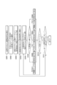
FIG. 1 is a block diagram of amanagement system 1 according to the first embodiment of the present invention. The management system 1 includes an input / output device 2, a design database 3, a management member selection unit 5, a related member selection unit 6, a boundary information creation unit 7, and a comparison result database 20.
(第一の実施形態に係る管理システムの構成)
図1は、本発明の第一の実施形態に係る管理システム1の構成ブロック図である。管理システム1は、入出力装置2と、設計データベース3と、管理部材選択部5と、関連部材選択部6と、境界情報作成部7と、比較結果データベース20と、を備える。 <First Embodiment>
(Configuration of management system according to the first embodiment)
FIG. 1 is a block diagram of a
入出力装置2は、少なくとも演算部、記憶部、通信部、表示部、操作部を備える汎用パーソナルコンピュータやタブレット端末等であり、管理者からの操作が可能である。
The input / output device 2 is a general-purpose personal computer, tablet terminal, or the like having at least a calculation unit, a storage unit, a communication unit, a display unit, and an operation unit, and can be operated by an administrator.
管理部材選択部5,関連部材選択部6,および境界情報作成部7の各機能部は、CPU(Central Processing Unit)、ASIC(Application Specific Integrated Circuit)、FPGA(Field Programmable Gate Array)などのPLD(Programmable Logic Device)などの電子回路により構成される。各機能部は、入出力装置2内に、または他の外部ハードウェア/ソフトウェアのいずれかで、構成されてもよい。後者の場合、各機能部は、入出力装置2とネットワークを通じて情報の送受信を行える。
Each functional unit of the management member selection unit 5, the related member selection unit 6, and the boundary information creation unit 7 is a PLD (Central Processing Unit), ASIC (Application Specific Integrated Circuit), FPGA (Field Programmable Gate Array), or the like. It is composed of electronic circuits such as Programmable Logic Device). Each functional unit may be configured within the input / output device 2 or in either other external hardware / software. In the latter case, each functional unit can send and receive information through the input / output device 2 and the network.
設計データベース3および比較結果データベース20は、ネットワークを介して通信可能に構成されたサーバコンピュータに記憶されている。該サーバコンピュータは、関連する機能部と通信が可能であり、関連する機能部と情報の送受信を行える。
The design database 3 and the comparison result database 20 are stored in a server computer configured to be able to communicate via a network. The server computer can communicate with the related functional unit and can send and receive information with the related functional unit.
設計データベース3には、管理対象となる建築物の設計BIMに基づく設計データ(建築物を構成する一つ一つの建築部材を3Dモデル形状で有したデータ。3Dモデルには面,線,点の形状も含まれる。以降、設計モデルとも称する)が記憶されている。設計データベース3は、図2に示すように、各建築部材に関し、部材識別情報(以下、部材ID)と,部材座標と,部材形状とを関連付ける設計テーブル31を備える。
The design database 3 contains design data based on the design BIM of the building to be managed (data in which each building member constituting the building is held in a 3D model shape. The 3D model contains surfaces, lines, and points. The shape is also included. Hereinafter, it is also referred to as a design model). As shown in FIG. 2, the design database 3 includes a design table 31 that associates member identification information (hereinafter, member ID), member coordinates, and member shape with respect to each building member.
比較結果データベース20には、管理部材と,管理部材に隣接する部材との,部材間の境界情報が記憶される。比較結果データベース20は、少なくとも、部材間の境界(隣接箇所)を管理する隣接箇所テーブル201と、隣接箇所において関連している部材を管理する関連部材テーブル202を有している。好ましくは、図3に示すように、隣接箇所テーブル201には、部材間の境界(隣接箇所)ごとに付けられた識別情報(以下、隣接箇所ID)と,隣接箇所の座標と,隣接箇所の形状とが関連付けて記憶される。隣接箇所の形状は、例えば、境界面の形状に関する情報であり、“平面”“凸面”“凹面”“曲面”などである。関連部材テーブル202には、隣接箇所IDと,管理対象となる部材(以下、“管理部材”)の部材IDと,管理部材に隣接し管理部材とともに隣接箇所を形成する部材(以下、“関連部材”)の部材ID(以下、こちらを関連部材IDと称する)とが関連付けて記憶される。
The comparison result database 20 stores boundary information between the management member and the member adjacent to the management member. The comparison result database 20 has at least an adjacent location table 201 that manages boundaries (adjacent locations) between members and a related member table 202 that manages related members at adjacent locations. Preferably, as shown in FIG. 3, the adjacent location table 201 includes identification information (hereinafter, adjacent location ID) assigned to each boundary (adjacent location) between members, coordinates of the adjacent location, and adjacent locations. It is stored in association with the shape. The shape of the adjacent portion is, for example, information regarding the shape of the boundary surface, such as "plane", "convex surface", "concave surface", and "curved surface". In the related member table 202, an adjacent portion ID, a member ID of a member to be managed (hereinafter, “management member”), and a member adjacent to the management member and forming an adjacent portion together with the management member (hereinafter, “related member”) are displayed. ") Member ID (hereinafter, this is referred to as a related member ID) is stored in association with the member ID.
管理部材選択部5,関連部材選択部6,および境界情報作成部7の各機能部については、次に記載する本形態に係る管理方法において説明する。
Each functional unit of the management member selection unit 5, the related member selection unit 6, and the boundary information creation unit 7 will be described in the management method according to the present embodiment described below.
(第一の実施形態に係る管理方法)
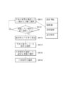
本形態による管理方法は、境界情報を管理するための比較結果データベース20を作成するためのデータ管理となる。図4は本発明の第一の実施形態に係る管理方法を示すフロー図であり、図5は同フローの作業イメージ図である。 (Management method according to the first embodiment)
The management method according to this embodiment is data management for creating acomparison result database 20 for managing boundary information. FIG. 4 is a flow chart showing a management method according to the first embodiment of the present invention, and FIG. 5 is a work image diagram of the same flow.
本形態による管理方法は、境界情報を管理するための比較結果データベース20を作成するためのデータ管理となる。図4は本発明の第一の実施形態に係る管理方法を示すフロー図であり、図5は同フローの作業イメージ図である。 (Management method according to the first embodiment)
The management method according to this embodiment is data management for creating a
本形態による管理処理が開始されると、ステップS1001で、管理部材選択部5は、設計テーブル31を読み出し、入出力装置2に設計モデルを表示するなどして、管理者に、管理対象となる部材“管理部材”を選択させる。管理者は、入出力装置2を介して管理部材を選択する(図5のS1001も参照)。
When the management process according to this embodiment is started, in step S1001, the management member selection unit 5 reads out the design table 31 and displays the design model on the input / output device 2, so that the manager becomes a management target. Have the member select the "management member". The administrator selects the management member via the input / output device 2 (see also S1001 in FIG. 5).
次に、ステップS1002に移行して、関連部材選択部6は、設計テーブル31を読み出し、設計テーブル31にある管理部材の座標および形状のデータを基に、管理部材に隣接する“関連部材”を自動で抽出するか、管理部材の周辺の設計モデルを入出力装置2に表示するなどして“関連部材”を管理者に選択させる(図5のS1002も参照)。
Next, in step S1002, the related member selection unit 6 reads out the design table 31, and based on the coordinate and shape data of the management member in the design table 31, selects the “related member” adjacent to the management member. The administrator is made to select the "related member" by automatically extracting the data or displaying the design model around the management member on the input / output device 2 (see also S1002 in FIG. 5).
次に、ステップS1003に移行して、境界情報作成部7は、管理部材の設計モデルと関連部材の設計モデルが隣接する隣接箇所を一つ選択する(図5のS1003も参照)。
Next, in step S1003, the boundary information creation unit 7 selects one adjacent portion where the design model of the management member and the design model of the related member are adjacent to each other (see also S1003 in FIG. 5).
次に、ステップS1004に移行して、境界情報作成部7は、ステップS1003で選択された隣接箇所について、隣接箇所IDを付け,隣接箇所IDと,隣接箇所座標と,隣接箇所形状(境界面の形状)と,管理部材の部材IDと,関連部材の関連部材IDとを,隣接箇所テーブル201および関連部材テーブル202の対応箇所に格納する(図5のS1004も参照)。
Next, in step S1004, the boundary information creation unit 7 assigns an adjacent location ID to the adjacent location selected in step S1003, and assigns the adjacent location ID, the adjacent location coordinates, and the adjacent location shape (of the boundary surface). The shape), the member ID of the management member, and the related member ID of the related member are stored in the corresponding locations of the adjacent location table 201 and the related member table 202 (see also S1004 in FIG. 5).
次に、ステップS1005に移行して、境界情報作成部7は、管理部材の設計モデルを確認し、管理部材の全ての関連部材について境界情報を作成したか確認する。全て作成していない場合はステップS1002に戻り未作成分を作成し(図5のS1005も参照)、全て作成した場合はフローを終了する。
Next, in step S1005, the boundary information creation unit 7 confirms the design model of the management member and confirms whether the boundary information has been created for all the related members of the management member. If not all have been created, the process returns to step S1002 to create the uncreated portion (see also S1005 in FIG. 5), and if all have been created, the flow ends.
以上、本形態の管理方法および管理システムによれば、設計データベース3に紐づけて作成された比較結果データベース20(隣接箇所テーブル201と関連部材テーブル202)によって、部材同士の境界情報がデータ管理される。
As described above, according to the management method and management system of this embodiment, the boundary information between members is data-managed by the comparison result database 20 (adjacent location table 201 and related member table 202) created in association with the design database 3. NS.
<第二の実施形態>
本形態による管理システムおよび管理方法は、第一の実施形態に追加的に適用されるものであり、さらに、計測データを反映させて境界情報を管理するものである。 <Second embodiment>
The management system and management method according to the present embodiment are additionally applied to the first embodiment, and further, the boundary information is managed by reflecting the measurement data.
(第二の実施形態に係る管理システムの構成)
図6は、本発明の第二の実施の形態に係る管理システム1’の構成ブロック図である。第一の実施形態と同一の構成については、同一の符号を用いて説明を割愛する。管理システム1’は、入出力装置2と、設計データベース3と、計測データベース4と、管理部材選択部5と、計測データ選択部8と,現状モデル作成部9と,境界情報選択部10と、隣接箇所比較部11と、境界情報作成部7と、比較結果データベース20と、を備える。 (Configuration of management system according to the second embodiment)
FIG. 6 is a block diagram of amanagement system 1 ′ according to a second embodiment of the present invention. The same components as those in the first embodiment will be omitted from the description using the same reference numerals. The management system 1'contains the input / output device 2, the design database 3, the measurement database 4, the management member selection unit 5, the measurement data selection unit 8, the current model creation unit 9, the boundary information selection unit 10, and the boundary information selection unit 10. An adjacent location comparison unit 11, a boundary information creation unit 7, and a comparison result database 20 are provided.
図6は、本発明の第二の実施の形態に係る管理システム1’の構成ブロック図である。第一の実施形態と同一の構成については、同一の符号を用いて説明を割愛する。管理システム1’は、入出力装置2と、設計データベース3と、計測データベース4と、管理部材選択部5と、計測データ選択部8と,現状モデル作成部9と,境界情報選択部10と、隣接箇所比較部11と、境界情報作成部7と、比較結果データベース20と、を備える。 (Configuration of management system according to the second embodiment)
FIG. 6 is a block diagram of a
計測データベース4には、スキャナ等を利用して得られた上記建築物の計測データ(座標情報をレジストレーションした点群データ,点データ、計測地点の座標情報を保持する画面データ,建築部材の施工誤差に関するデータ)が記憶されている。計測データには、計測点の識別情報(以下、点群ID)が付与されている。計測データベース4は、少なくとも、図7に示すように、計測点毎に、点群IDと点座標とを関連付けた計測テーブル41を備える。
In the measurement database 4, the measurement data of the building obtained by using a scanner or the like (point cloud data in which coordinate information is registered, point data, screen data for holding coordinate information of measurement points, construction of building members) Data about the error) is stored. Identification information of measurement points (hereinafter, point cloud ID) is added to the measurement data. The measurement database 4 includes, at least, as shown in FIG. 7, a measurement table 41 in which the point cloud ID and the point coordinates are associated with each measurement point.
計測データ選択部8,現状モデル作成部9,境界情報選択部10、隣接箇所比較部11も、他の機能部と同様、電子回路により構成される。計測データ選択部8,現状モデル作成部9,境界情報選択部10、隣接箇所比較部11については、次に記載する本形態に係る管理方法において説明する。
The measurement data selection unit 8, the current model creation unit 9, the boundary information selection unit 10, and the adjacent location comparison unit 11 are also composed of electronic circuits like other functional units. The measurement data selection unit 8, the current model creation unit 9, the boundary information selection unit 10, and the adjacent location comparison unit 11 will be described in the management method according to the present embodiment described below.
(第二の実施形態に係る管理方法)
図8は本発明の第二の実施形態に係る管理方法を示すフロー図、図9は同管理フローの作業イメージ図である。第一の実施形態と同一のステップについては、同一のステップ符号を引用して説明を割愛する。 (Management method according to the second embodiment)
FIG. 8 is a flow diagram showing a management method according to a second embodiment of the present invention, and FIG. 9 is a work image diagram of the management flow. For the same steps as in the first embodiment, the same step reference numerals are used and the description thereof will be omitted.
本形態による管理処理が開始されると、ステップS2001で、管理部材選択部5は、ステップS1001と同様に、管理者に、設計テーブル31から管理部材を選択させる(図9のS2001も参照)。
When the management process according to this embodiment is started, in step S2001, the management member selection unit 5 causes the manager to select the management member from the design table 31 as in step S1001 (see also S2001 in FIG. 9).
次に、ステップS2002に移行して、計測データ選択部8は、計測テーブル41に記憶されている計測点の点座標を読み出し、ステップS2001で選択された管理部材の部材座標と略対応する計測点を抽出するか、管理者に入出力装置2を介して選択させる。このとき、座標が完全一致するものだけではなく、予め設定した誤差値内に入る計測点は選択される。
Next, in step S2002, the measurement data selection unit 8 reads out the point coordinates of the measurement points stored in the measurement table 41, and the measurement points substantially correspond to the member coordinates of the management member selected in step S2001. Is extracted or the administrator is made to select via the input / output device 2. At this time, not only the points whose coordinates match exactly but also the measurement points within the preset error value are selected.
ここで、予め、計測点がどの建築部材のものなのかが特定されており、計測テーブル41において、計測点に設計テーブル31と対応付く部材IDが付けられるのも好ましい。この場合、先にステップS2001で管理部材の部材IDを基に計測データを選択し、次のステップS2002で管理部材の設計モデルを選択する流れとしてもよい。
Here, it is preferable that the measurement point belongs to which building member in advance, and in the measurement table 41, the member ID corresponding to the design table 31 is attached to the measurement point. In this case, the measurement data may be selected first based on the member ID of the management member in step S2001, and the design model of the management member may be selected in the next step S2002.
次に、ステップS2003に移行して、現状モデル作成部9は、管理部材に関し、設計モデルと計測データを利用して、計測データで設計モデルの形状,座標,回転,傾きを修正し、管理部材の現状モデルを作成する(図9のS2003も参照)。
Next, in step S2003, the current model creation unit 9 uses the design model and the measurement data to correct the shape, coordinates, rotation, and inclination of the design model with the measurement data, and the management member. (See also S2003 in FIG. 9).
次に、ステップS2004に移行して、境界情報選択部10は、比較結果データベース20を参照し、管理部材が持つ隣接箇所を一つ、管理者に選択させる。管理者は、管理部材の設計モデルまたは隣接箇所IDを基に、隣接箇所を一つ選択する(図9のS2004も参照)。
Next, in step S2004, the boundary information selection unit 10 refers to the comparison result database 20 and causes the administrator to select one adjacent location of the management member. The manager selects one adjacent location based on the design model of the management member or the adjacent location ID (see also S2004 in FIG. 9).
次に、ステップS2005に移行して、隣接箇所比較部11は、隣接箇所テーブル201から読みだした隣接箇所形状と、隣接箇所座標における現状モデルの形状と、を比較する。
Next, in step S2005, the adjacent location comparison unit 11 compares the adjacent location shape read from the adjacent location table 201 with the shape of the current model in the adjacent location coordinates.
次に、ステップS2006に移行して、境界情報作成部7は、隣接箇所形状と現状モデルの形状に干渉または空間があるか判断し、比較箇所の属性を判断する。一例として、隣接箇所の形状が平面であるのに対し、比較した箇所で現状モデルが凸面となっている場合(図9のS2006-1参照)、その比較箇所では「干渉あり」としてステップS2007に移行する。一方、比較した箇所で現状モデルが凹面となっている場合(図9のS2006-2参照)、その比較箇所では「空間があり」としてステップS2008に移行する。隣接箇所形状も比較箇所の現状モデルも平面である場合、その比較箇所は「設計通り」としてステップS2009に移行する。なお、隣接箇所形状と現状モデルの形状の比較では、予め設定された設計誤差範囲内である場合は、設計通りとされるのも好ましい。
Next, in step S2006, the boundary information creation unit 7 determines whether there is interference or space between the shape of the adjacent portion and the shape of the current model, and determines the attribute of the comparison portion. As an example, when the shape of the adjacent portion is flat, but the current model is convex at the comparison location (see S2006-1 in FIG. 9), the comparison location is regarded as "interfering" and the step S2007 is performed. Transition. On the other hand, when the current model has a concave surface at the comparison location (see S2006-2 in FIG. 9), the process proceeds to step S2008 as "there is space" at the comparison location. When both the shape of the adjacent portion and the current model of the comparison portion are flat, the comparison portion is set as “as designed” and the process proceeds to step S2009. In the comparison between the shape of the adjacent portion and the shape of the current model, if it is within the preset design error range, it is preferable that the shape is as designed.
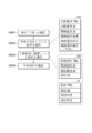
境界情報作成部7は、図10に示すように、比較結果データベース20に、比較箇所テーブル203を作成する。比較箇所テーブル203には、好ましくは、比較箇所ごとに付けられた識別情報(以下、比較箇所ID)と,隣接箇所IDと,比較箇所座標と,比較箇所形状と,比較箇所の属性として「干渉」または「乖離」または「問題なし」,が関連付けて記憶される。
As shown in FIG. 10, the boundary information creation unit 7 creates the comparison location table 203 in the comparison result database 20. In the comparison location table 203, preferably, the identification information (hereinafter referred to as the comparison location ID) attached to each comparison location, the adjacent location ID, the comparison location coordinates, the comparison location shape, and the attributes of the comparison location are "interference". "Or" divergence "or" no problem "is memorized in association with each other.
ステップS2007に移行すると、境界情報作成部7は、比較箇所ID,隣接箇所ID,比較箇所座標,比較箇所形状とともに、比較箇所の属性を「干渉」として、比較箇所テーブル203に格納し、ステップS2010に移行する。
When the process proceeds to step S2007, the boundary information creation unit 7 stores the comparison location ID, the adjacent location ID, the comparison location coordinates, the comparison location shape, and the comparison location attribute as "interference" in the comparison location table 203, and stores the comparison location table 203 in step S2010. Move to.
ステップS2008に移行すると、境界情報作成部7は、比較箇所ID,隣接箇所ID,比較箇所座標,比較箇所形状とともに、比較箇所の属性を「乖離」として、比較箇所テーブル203に格納し、ステップS2010に移行する。
When the process proceeds to step S2008, the boundary information creation unit 7 stores the comparison location ID, the adjacent location ID, the comparison location coordinates, the comparison location shape, and the comparison location attribute as "deviation" in the comparison location table 203, and stores the comparison location table 203 in step S2010. Move to.
ステップS2009に移行すると、境界情報作成部7は、比較箇所ID,隣接箇所ID,比較箇所座標,比較箇所形状とともに、比較箇所の属性を「問題なし」として、比較箇所テーブル203に格納し、ステップS2010に移行する。
When the process proceeds to step S2009, the boundary information creation unit 7 stores the comparison location ID, the adjacent location ID, the comparison location coordinates, the comparison location shape, and the comparison location attribute as "no problem" in the comparison location table 203, and steps. Move to S2010.
ステップS2010に移行すると、境界情報作成部7は、管理者に、係る隣接箇所での比較作業を終了するか尋ねる。管理者が係る隣接箇所で他の比較箇所での比較を続ける場合はステップS2005に戻り、係る隣接箇所での比較を止める場合はステップS2011に移行する。
When the process proceeds to step S2010, the boundary information creation unit 7 asks the administrator whether to end the comparison work at the adjacent location. If the administrator wants to continue the comparison at another comparison point at the adjacent point, the process returns to step S2005, and if the administrator stops the comparison at the adjacent point, the process proceeds to step S2011.
ステップS2011に移行すると、境界情報作成部7は、管理部材の全ての隣接箇所に対して比較作業を終了するか尋ねる。管理者が他の隣接箇所での比較を続ける場合はステップS2004に戻り、全ての隣接箇所での比較を止める場合はフローを終了する。
When the process proceeds to step S2011, the boundary information creation unit 7 asks whether the comparison work is completed for all the adjacent parts of the management member. If the administrator wants to continue the comparison at other adjacent points, the process returns to step S2004, and if the administrator stops the comparison at all the adjacent points, the flow ends.
なお、補足として、比較箇所は、対象となる隣接箇所(エリア)を細かく分解し、分解したエリア単位で確認される。分解能の設定は、管理者が手動で設定してもよいし、隣接箇所比較部11が3Dモデルの描画粒度に合わせて自動設定してもよい。ステップS2005からステップS2010の作業イメージを図11と図12に示す。境界情報作成部7は、対象となる隣接箇所の比較箇所を全て確認した後、図11および図12に示すように、干渉,乖離,問題なしの属性ごとに分けた比較箇所エリアを作成し、データ管理するのも好ましい。
As a supplement, the comparison points are confirmed by decomposing the target adjacent points (areas) into small pieces and disassembling each area. The resolution may be set manually by the administrator, or may be automatically set by the adjacent location comparison unit 11 according to the drawing particle size of the 3D model. The working images of steps S2005 to S2010 are shown in FIGS. 11 and 12. After confirming all the comparison points of the target adjacent points, the boundary information creation unit 7 creates a comparison point area divided for each attribute of interference, divergence, and no problem as shown in FIGS. 11 and 12. Data management is also preferable.
以上、本形態の管理方法および管理システムによれば、設計モデルに計測データを反映させた上で、予めデータ管理された境界情報に基づいて、隣接箇所で部材同士が干渉するかどうか検証することができる。さらに、隣接箇所において部材同士が離れている場合、隣接箇所に乖離があるということをデータとして管理することができる。また、干渉の位置と乖離の位置は、座標まで明らかにして、比較結果データベース20に記憶することができる。
As described above, according to the management method and management system of this embodiment, after reflecting the measurement data in the design model, it is verified whether or not the members interfere with each other at the adjacent points based on the boundary information managed in advance. Can be done. Further, when the members are separated from each other in the adjacent portion, it is possible to manage as data that there is a dissociation in the adjacent portion. Further, the position of interference and the position of dissociation can be clarified up to the coordinates and stored in the comparison result database 20.
<第三の実施形態>
本形態による管理システムおよび管理方法は、第二の実施形態の境界情報に加えて、境界部分の具体的な形状まで含めて管理するものである。 <Third embodiment>
The management system and management method according to the present embodiment manages the boundary information including the specific shape of the boundary portion in addition to the boundary information of the second embodiment.
(第三の実施形態に係る管理システムの構成)
図13は、本発明の第三の実施の形態に係る管理システム1”の構成ブロック図である。前述の実施形態と同一の構成については、同一の符号を用いて説明を割愛する。管理システム1”は、第二の実施形態の構成に、境界面作成部12と境界モデル作成部13が追加される。 (Configuration of management system according to the third embodiment)
FIG. 13 is a configuration block diagram of themanagement system 1 ”according to the third embodiment of the present invention. The same configuration as that of the above-described embodiment will be omitted from the description by using the same reference numerals. For 1 ”, a boundary surface creating unit 12 and a boundary model creating unit 13 are added to the configuration of the second embodiment.
図13は、本発明の第三の実施の形態に係る管理システム1”の構成ブロック図である。前述の実施形態と同一の構成については、同一の符号を用いて説明を割愛する。管理システム1”は、第二の実施形態の構成に、境界面作成部12と境界モデル作成部13が追加される。 (Configuration of management system according to the third embodiment)
FIG. 13 is a configuration block diagram of the
境界面作成部12,境界モデル作成部13も、他の機能部と同様、電子回路により構成される。境界面作成部12,境界モデル作成部13については、次に記載する本形態に係る管理方法において説明する。
The boundary surface creation unit 12 and the boundary model creation unit 13 are also composed of electronic circuits like other functional units. The boundary surface creating unit 12 and the boundary model creating unit 13 will be described in the management method according to the present embodiment described below.
(第三の実施形態に係る管理方法)
図14は本発明の第三の実施形態に係る管理方法を示すフロー図、図15は同管理フローの作業イメージ図である。第二の実施形態と同一のステップについては、同一のステップ符号を引用して説明を割愛する。 (Management method according to the third embodiment)
FIG. 14 is a flow diagram showing a management method according to a third embodiment of the present invention, and FIG. 15 is a work image diagram of the management flow. For the same steps as in the second embodiment, the same step reference numerals are used and the description thereof will be omitted.
本形態による管理処理が開始されると、ステップS3001で、管理部材選択部5はステップS2001と同様に管理部材を選択させ、ステップS3002で、計測データ選択部8はステップS2002と同様に管理部材の計測データを選択する。
When the management process according to this embodiment is started, in step S3001, the management member selection unit 5 selects the management member in the same manner as in step S2001, and in step S3002, the measurement data selection unit 8 selects the management member in the same manner as in step S2002. Select the measurement data.
次に、ステップS3003に移行して、ステップS2003と同様に、現状モデル作成部9は管理部材の現状モデルを作成する(図15のS3003も参照)。
Next, the process proceeds to step S3003, and the current model creation unit 9 creates the current model of the management member in the same manner as in step S2003 (see also S3003 in FIG. 15).
次に、ステップS3004に移行して、ステップS2004と同様に、境界情報選択部10は、比較結果データベース20を参照し、管理部材が持つ隣接箇所を一つ、管理者に選択させる。
Next, the process proceeds to step S3004, and the boundary information selection unit 10 refers to the comparison result database 20 and causes the administrator to select one adjacent portion of the management member, as in step S2004.
次に、ステップS3005に移行すると、境界面作成部12は、隣接箇所テーブル201(比較結果データベース20)を参照して、ステップS3004で選択された隣接箇所IDの隣接箇所座標と隣接箇所形状から、当該隣接箇所の境界面の設計モデル(以下、境界面モデル)を作成する(図15のS3005も参照)。
Next, when the process proceeds to step S3005, the boundary surface creating unit 12 refers to the adjacent location table 201 (comparison result database 20), and obtains the adjacent location coordinates and the adjacent location shape of the adjacent location ID selected in step S3004. A design model of the boundary surface of the adjacent portion (hereinafter, boundary surface model) is created (see also S3005 in FIG. 15).
次に、ステップS3006に移行して、隣接箇所比較部11は、隣接箇所座標における現状モデルの形状と、ステップS3005で作成した境界面モデルの形状を比較する。
Next, in step S3006, the adjacent location comparison unit 11 compares the shape of the current model in the coordinates of the adjacent location with the shape of the boundary surface model created in step S3005.
次に、ステップS3007に移行して、境界情報作成部7は、境界面モデルと現状モデルとに干渉または空間があるか判断し、比較箇所の属性を判断する。一例として、境界面モデルが平面であるのに対し、比較した箇所(座標)で現状モデルが凸面となっている場合(図15のS3007-1参照)、その比較箇所では干渉ありとしてステップS3008に移行する。一方、比較した箇所(座標)で現状モデルが凹面となっている場合(図15のS3007-2参照)、その比較箇所では空間があるとしてステップS3009に移行する。境界面モデルも比較した箇所の現状モデルも平面である場合、その比較箇所は「設計通り」としてステップS3010に移行する。なお、境界面モデルと現状モデルの比較では、予め設定された設計誤差範囲内である場合は、設計通りとされるのも好ましい。
Next, in step S3007, the boundary information creation unit 7 determines whether there is interference or space between the boundary surface model and the current model, and determines the attributes of the comparison points. As an example, when the boundary surface model is a plane, but the current model is a convex surface at the comparison location (coordinates) (see S3007-1 in FIG. 15), it is assumed that there is interference at the comparison location, and step S3008 is performed. Transition. On the other hand, when the current model is concave at the compared points (coordinates) (see S3007-2 in FIG. 15), it is assumed that there is space at the compared points, and the process proceeds to step S3009. If both the boundary surface model and the current model of the comparison location are flat, the comparison location is set to "as designed" and the process proceeds to step S3010. In the comparison between the boundary surface model and the current model, it is preferable that the design is as designed if it is within the preset design error range.
ステップS3008に移行すると、境界モデル作成部13が、この比較箇所において干渉部分の境界モデルを作成する(図15のS3008参照)。境界情報作成部7は、比較箇所IDと,隣接箇所IDと,境界モデルに基づく比較箇所座標,比較箇所形状と、比較箇所の属性「干渉」とを、比較箇所テーブル203に格納して、ステップS3011に移行する。
When the process proceeds to step S3008, the boundary model creation unit 13 creates a boundary model of the interference portion at this comparison point (see S3008 in FIG. 15). The boundary information creation unit 7 stores the comparison location ID, the adjacent location ID, the comparison location coordinates based on the boundary model, the comparison location shape, and the comparison location attribute "interference" in the comparison location table 203, and steps. Move to S3011.
ステップS3009に移行すると、境界モデル作成部13は、この比較箇所における空間部分のモデル、すなわち乖離部分の境界モデルを作成する(図15のS3009参照)。境界情報作成部7は、比較箇所IDと,隣接箇所IDと,境界モデルに基づく比較箇所座標,比較箇所形状と、比較箇所の属性「乖離」とを、比較箇所テーブル203に格納して、ステップS3011に移行する。
When moving to step S3009, the boundary model creation unit 13 creates a model of the spatial portion at this comparison point, that is, a boundary model of the divergent portion (see S3009 in FIG. 15). The boundary information creation unit 7 stores the comparison location ID, the adjacent location ID, the comparison location coordinates based on the boundary model, the comparison location shape, and the comparison location attribute "dissociation" in the comparison location table 203, and steps. Move to S3011.
ステップS3010に移行すると、境界モデル作成部13は、この比較箇所の境界モデルを作成する。境界情報作成部7は、比較箇所IDと,隣接箇所IDと,境界モデルに基づく比較箇所座標,比較箇所形状と、比較箇所の属性「問題なし」とを、比較箇所テーブル203に格納して、ステップS3011に移行する。
Moving to step S3010, the boundary model creation unit 13 creates a boundary model of this comparison point. The boundary information creation unit 7 stores the comparison location ID, the adjacent location ID, the comparison location coordinates based on the boundary model, the comparison location shape, and the comparison location attribute "no problem" in the comparison location table 203. The process proceeds to step S3011.
ステップS3011に移行すると、境界情報作成部7は、管理者に、係る隣接箇所での比較作業を終了するか尋ねる。管理者が係る隣接箇所で他の比較箇所の比較を続ける場合はステップS3006に戻り、係る隣接箇所での比較を止める場合はステップS3012に移行する。
When the process proceeds to step S3011, the boundary information creation unit 7 asks the administrator whether to end the comparison work at the adjacent location. When the administrator continues to compare other comparison points at the adjacent points, the process returns to step S3006, and when the administrator stops the comparison at the adjacent points, the process proceeds to step S3012.
ステップS3012に移行すると、境界情報作成部7は、管理部材の全ての隣接箇所に対して比較作業を終了するか尋ねる。管理者が他の隣接箇所での比較を続ける場合はステップS3004に戻り、全ての隣接箇所での比較を止める場合はフローを終了する。
When the process proceeds to step S3012, the boundary information creation unit 7 asks whether the comparison work is completed for all the adjacent parts of the management member. If the administrator wants to continue the comparison at other adjacent points, the process returns to step S3004, and if the administrator stops the comparison at all the adjacent points, the flow ends.
以上、本形態の管理方法および管理システムによれば、第二の実施形態に加えて、干渉または乖離の部分の境界モデルを作成して、境界部分の具体的な形状をデータ管理することができる。
As described above, according to the management method and management system of the present embodiment, in addition to the second embodiment, it is possible to create a boundary model of the interference or dissociation portion and manage data on the specific shape of the boundary portion. ..
<第四の実施形態>
本形態による管理システムおよび管理方法は、第一の実施形態で作成された比較結果データベース20(関連部材テーブル202)のデータを活用する例を示すものであり、境界情報を管理することで可能となるデータ確認のための構成および方法を示すものである。第一の実施形態と同一の構成については、同一の符号を用いて説明を割愛する。 <Fourth Embodiment>
The management system and management method according to this embodiment show an example of utilizing the data of the comparison result database 20 (related member table 202) created in the first embodiment, and can be performed by managing the boundary information. It shows the configuration and method for confirming the data. The same components as those in the first embodiment will be omitted from the description using the same reference numerals.
(第四の実施形態に係る管理システムの構成)
図16は、本発明の第四の実施の形態に係る管理システム100の構成ブロック図である。管理システム100は、入出力装置2と、設計データベース3と、関連部材確認部14と、比較結果データベース20と、を備える。関連部材確認部14も、他の機能部と同様、電子回路により構成される。関連部材確認部14については、次に記載する本形態に係る管理方法において説明する。 (Structure of management system according to the fourth embodiment)
FIG. 16 is a block diagram of amanagement system 100 according to a fourth embodiment of the present invention. The management system 100 includes an input / output device 2, a design database 3, a related member confirmation unit 14, and a comparison result database 20. The related member confirmation unit 14 is also composed of an electronic circuit like the other functional units. The related member confirmation unit 14 will be described in the management method according to the present embodiment described below.
図16は、本発明の第四の実施の形態に係る管理システム100の構成ブロック図である。管理システム100は、入出力装置2と、設計データベース3と、関連部材確認部14と、比較結果データベース20と、を備える。関連部材確認部14も、他の機能部と同様、電子回路により構成される。関連部材確認部14については、次に記載する本形態に係る管理方法において説明する。 (Structure of management system according to the fourth embodiment)
FIG. 16 is a block diagram of a
(第四の実施形態に係る管理方法)
図17は本発明の第四の実施形態に係る関連部材の管理方法を示すフロー図である。本確認フローが開始されると、ステップS4001に移行して、関連部材確認部14が部材を訊ねるので、管理者は、確認の対象となる「確認部材」を設計データベース3から選択する。次に、ステップS4002に移行して、関連部材確認部14は、比較結果データベース20から関連部材テーブル202を読み出し、確認部材の部材IDを有する隣接箇所をピックアップして、管理者に確認したい隣接箇所を選択させる。次に、ステップS4003に移行して、関連部材確認部14は、関連部材テーブル202から隣接箇所IDで紐づく関連部材を読み出す。これにより、管理者は、確認部材の関連部材を確認することができる。 (Management method according to the fourth embodiment)
FIG. 17 is a flow chart showing a method of managing related members according to the fourth embodiment of the present invention. When the main confirmation flow is started, the process proceeds to step S4001 and the related member confirmation unit 14 asks for the member. Therefore, the administrator selects the “confirmation member” to be confirmed from thedesign database 3. Next, in step S4002, the related member confirmation unit 14 reads the related member table 202 from the comparison result database 20, picks up the adjacent portion having the member ID of the confirmation member, and wants to confirm with the administrator the adjacent portion. Let me select. Next, in step S4003, the related member confirmation unit 14 reads out the related member associated with the adjacent portion ID from the related member table 202. As a result, the manager can confirm the related member of the confirmation member.
図17は本発明の第四の実施形態に係る関連部材の管理方法を示すフロー図である。本確認フローが開始されると、ステップS4001に移行して、関連部材確認部14が部材を訊ねるので、管理者は、確認の対象となる「確認部材」を設計データベース3から選択する。次に、ステップS4002に移行して、関連部材確認部14は、比較結果データベース20から関連部材テーブル202を読み出し、確認部材の部材IDを有する隣接箇所をピックアップして、管理者に確認したい隣接箇所を選択させる。次に、ステップS4003に移行して、関連部材確認部14は、関連部材テーブル202から隣接箇所IDで紐づく関連部材を読み出す。これにより、管理者は、確認部材の関連部材を確認することができる。 (Management method according to the fourth embodiment)
FIG. 17 is a flow chart showing a method of managing related members according to the fourth embodiment of the present invention. When the main confirmation flow is started, the process proceeds to step S4001 and the related member confirmation unit 14 asks for the member. Therefore, the administrator selects the “confirmation member” to be confirmed from the
本形態の管理方法および管理システムによれば、部材同士の境界情報を基に、確認対象となる部材に隣接する関連部材をすぐに特定することができる。また、確認部材に対する関連部材の数もすぐに特定することができるので、確認部材の施工ずれが後の作業へどれだけ影響するか、確認把握することも可能になる。
According to the management method and management system of this embodiment, it is possible to immediately identify the related member adjacent to the member to be confirmed based on the boundary information between the members. Further, since the number of related members with respect to the confirmation member can be immediately specified, it is possible to confirm and grasp how much the construction deviation of the confirmation member affects the subsequent work.
<第五の実施形態>
本形態による管理システムおよび管理方法は、第二または第三の実施形態で作成された比較結果データベース20(関連部材テーブル202および比較箇所テーブル203)のデータを活用する例を示すものであり、境界情報を管理することで可能となるデータ確認のための構成及び方法を示すものである。前述までの実施形態と同一の構成については、同一の符号を用いて説明を割愛する。また、以下は、第二の実施形態で作成された比較箇所テーブル203を例にして説明するが、第三の実施形態で作成された比較箇所テーブル203を用いても同様である。 <Fifth Embodiment>
The management system and management method according to the present embodiment show an example of utilizing the data of the comparison result database 20 (related member table 202 and comparison location table 203) created in the second or third embodiment, and show a boundary. It shows the configuration and method for data confirmation that is possible by managing information. The same components as those of the above-described embodiments will be omitted from the description by using the same reference numerals. Further, the following will be described by taking the comparison location table 203 created in the second embodiment as an example, but the same applies to the comparison location table 203 created in the third embodiment.
(第五の実施形態に係る管理システムの構成)
図18は、本発明の第五の実施の形態に係る管理システム100’の構成ブロック図である。管理システム100’は、入出力装置2と、管理箇所・部材確認部15と、比較結果データベース20と、を備える。管理箇所・部材確認部15も、他の機能部と同様、電子回路により構成される。管理箇所・部材確認部15については、次に記載する本形態に係る管理方法において説明する。 (Structure of management system according to fifth embodiment)
FIG. 18 is a block diagram of amanagement system 100 ′ according to a fifth embodiment of the present invention. The management system 100'includes an input / output device 2, a management location / member confirmation unit 15, and a comparison result database 20. The management location / member confirmation unit 15 is also composed of an electronic circuit like the other functional units. The management location / member confirmation unit 15 will be described in the management method according to the present embodiment described below.
図18は、本発明の第五の実施の形態に係る管理システム100’の構成ブロック図である。管理システム100’は、入出力装置2と、管理箇所・部材確認部15と、比較結果データベース20と、を備える。管理箇所・部材確認部15も、他の機能部と同様、電子回路により構成される。管理箇所・部材確認部15については、次に記載する本形態に係る管理方法において説明する。 (Structure of management system according to fifth embodiment)
FIG. 18 is a block diagram of a
(第五の実施形態に係る管理方法-1の1)
図19は本発明の第五の実施形態に係る干渉箇所の管理方法を示す確認フロー図であり、図20は対比のための従来の干渉箇所の管理方法を示す確認フロー図である。 (Management method-1-1 according to the fifth embodiment)
FIG. 19 is a confirmation flow diagram showing a method of managing interference points according to a fifth embodiment of the present invention, and FIG. 20 is a confirmation flow diagram showing a conventional method of managing interference points for comparison.
最初に、図20を用いて従来の確認フローについて説明する。設計モデルに計測データを反映させたものに「干渉箇所」が発生しているか確認したい時、従来では、管理者は、まずステップS5111で、設計データベースから、干渉の有無を確認したい部材を手動で選択する。次に、管理者は、ステップS5112に進んで、確認したい部材を全て選択したかチェックする。選択していないものがあればステップS5111に戻り、全て選択した場合はステップS5113に進む。ステップS5113に進むと、チェックプログラムを有する演算部が、選択された部材の干渉を算出する。次に、ステップS5114に進んで、演算部はステップS5113の結果から干渉が発生している干渉部材を選択する。次に、ステップS5115に進み、管理者はステップS5114の結果から干渉箇所を確認したい部材を手動で選択する。次に、ステップS5116に進んではじめて、管理者は選択した部材の干渉箇所を確認することができる。
First, the conventional confirmation flow will be described with reference to FIG. When it is desired to confirm whether or not an "interference point" has occurred in the design model reflecting the measurement data, the administrator has conventionally manually selected the member whose presence or absence of interference is to be confirmed from the design database in step S5111. select. Next, the administrator proceeds to step S5112 and checks whether all the members to be confirmed have been selected. If there are any items that have not been selected, the process returns to step S5111, and if all items have been selected, the process proceeds to step S5113. Proceeding to step S5113, the arithmetic unit having the check program calculates the interference of the selected member. Next, the process proceeds to step S5114, and the calculation unit selects an interference member in which interference is occurring from the result of step S5113. Next, the process proceeds to step S5115, and the administrator manually selects a member whose interference point is to be confirmed from the result of step S5114. Next, the administrator can confirm the interference point of the selected member only after proceeding to step S5116.
これに対し、本形態では、図19に示すように、設計モデルに計測データを反映させたものに「干渉箇所」が発生しているか確認したい時、管理箇所・部材確認部15が機能する。ステップS5011に移行すると、管理箇所・部材確認部15が確認する属性を訊ねるので、管理者は「干渉」を選択する。すると、ステップS5012に移行して、管理箇所・部材確認部15が、比較結果データベース20から比較箇所テーブル203を読み出し、属性が「干渉」となっている隣接箇所をピックアップするので、管理者は管理したい箇所を選択する。選択後、ステップS5013に移行して、管理者は、干渉箇所を確認することができる。
On the other hand, in this embodiment, as shown in FIG. 19, when it is desired to confirm whether or not an "interference point" is generated in the design model reflecting the measurement data, the management point / member confirmation unit 15 functions. When the process proceeds to step S5011, the manager selects "interference" because the management location / member confirmation unit 15 asks for the attribute to be confirmed. Then, in step S5012, the management location / member confirmation unit 15 reads the comparison location table 203 from the comparison result database 20 and picks up the adjacent location whose attribute is "interference", so that the administrator manages it. Select the part you want to do. After the selection, the process proceeds to step S5013, and the administrator can confirm the interference location.
すなわち、「干渉箇所」はすでに比較箇所テーブル203によって管理されているので、管理者は「干渉」の属性データを基に、干渉箇所をすぐに選択・確認することができる。
That is, since the "interference point" is already managed by the comparison point table 203, the administrator can immediately select and confirm the interference point based on the attribute data of "interference".
(第五の実施形態に係る管理方法-1の2)
図21は本発明の第五の実施形態に係る乖離箇所の管理方法を示すフロー図である。 (Management method-1-2 according to the fifth embodiment)
FIG. 21 is a flow chart showing a method of managing a divergence portion according to a fifth embodiment of the present invention.
図21は本発明の第五の実施形態に係る乖離箇所の管理方法を示すフロー図である。 (Management method-1-2 according to the fifth embodiment)
FIG. 21 is a flow chart showing a method of managing a divergence portion according to a fifth embodiment of the present invention.
設計モデルに計測データを反映させたものに「乖離箇所」が発生しているか確認したい時、従来では、空間や部材同士の離れを検出する手段が無いことから、乖離箇所を確認することはできなかった。
When you want to check whether a "dissociation point" has occurred in the design model that reflects the measurement data, you can check the dissociation point because there is no means to detect the space or the separation between the members in the past. There wasn't.
これに対し、本形態では、図21に示すように、設計モデルに計測データを反映させたものに「乖離箇所」が発生しているか確認したい時、管理箇所・部材確認部15が機能する。ステップS5021に移行すると、管理箇所・部材確認部15が確認する属性を訊ねるので、管理者は「乖離」を選択する。すると、ステップS5022に移行して、管理箇所・部材確認部15が、比較箇所テーブル203を読み出し、属性が「乖離」となっている隣接箇所をピックアップするので、管理者は管理したい箇所を選択する。選択後、ステップS5023に移行して、管理者は、乖離箇所を確認することができる。
On the other hand, in this embodiment, as shown in FIG. 21, when it is desired to confirm whether or not a "dissociation point" has occurred in the design model reflecting the measurement data, the management point / member confirmation unit 15 functions. When the process proceeds to step S5021, the manager selects "dissociation" because the management location / member confirmation unit 15 asks for the attribute to be confirmed. Then, in step S5022, the management location / member confirmation unit 15 reads out the comparison location table 203 and picks up the adjacent location whose attribute is "difference". Therefore, the administrator selects the location to be managed. .. After the selection, the process proceeds to step S5023, and the administrator can confirm the deviation point.
すなわち、「乖離箇所」はすでに比較箇所テーブル203によって管理されているので、管理者は「乖離」の属性データを基に、乖離箇所をすぐに選択・確認することができる。
That is, since the "dissociation point" is already managed by the comparison point table 203, the administrator can immediately select and confirm the dissociation point based on the attribute data of the "dissociation".
(第五の実施形態に係る管理方法-1の3)
図22は本発明の第五の実施形態に係る問題なしの箇所の管理方法を示す確認フロー図である。 (Management method-1-3 according to the fifth embodiment)
FIG. 22 is a confirmation flow diagram showing a method of managing a problem-free portion according to the fifth embodiment of the present invention.
図22は本発明の第五の実施形態に係る問題なしの箇所の管理方法を示す確認フロー図である。 (Management method-1-3 according to the fifth embodiment)
FIG. 22 is a confirmation flow diagram showing a method of managing a problem-free portion according to the fifth embodiment of the present invention.
設計モデルに計測データを反映させたものが、設計通りとなっている箇所(以下、「問題なしの箇所」という)を確認したい時は、図22に示すように、管理箇所・部材確認部15を機能させて、ステップS5031で属性「問題なし」を選択する。次に、ステップS5032に移行して、管理箇所・部材確認部15が、比較箇所テーブル203を読み出し、属性が「問題なし」となっている隣接箇所をピックアップするので、管理者は管理したい箇所を選択する。選択後、ステップS5033に移行して、管理者は、設計通りとなっている箇所を確認することができる。
When you want to confirm the part where the measurement data is reflected in the design model as designed (hereinafter referred to as "the part without problem"), as shown in FIG. 22, the management part / member confirmation unit 15 Is made to function, and the attribute "no problem" is selected in step S5031. Next, in step S5032, the management location / member confirmation unit 15 reads out the comparison location table 203 and picks up the adjacent location whose attribute is "no problem", so that the administrator wants to manage the location. select. After the selection, the process proceeds to step S5033, and the administrator can confirm the portion as designed.
(第五の実施形態に係る管理方法-2の1)
図23は本発明の第五の実施形態に係る干渉部材の管理方法を示す確認フロー図であり、図24は対比のための従来の干渉部材の管理方法を示す確認フロー図である。 (Management method-2-1 according to the fifth embodiment)
FIG. 23 is a confirmation flow diagram showing a management method of the interference member according to the fifth embodiment of the present invention, and FIG. 24 is a confirmation flow diagram showing a conventional management method of the interference member for comparison.
最初に、図24を用いて従来の確認フローについて説明する。設計モデルに計測データを反映させたものに「干渉が発生している部材」(以下、干渉部材)があるか確認したい時、従来では、管理者は、まずステップS5411で、設計データベースから、干渉の有無を確認したい部材を手動で選択する。次に、管理者は、ステップS5412に進んで、確認したい部材を全て選択したかチェックする。選択していないものがあればステップS5411に戻り、全て選択した場合はステップS5413に進む。ステップS5413に進むと、チェックプログラムを有する演算部が、ステップS5412で選択された部材の干渉を算出する。次に、ステップS5414に進んで、演算部はステップS5413の結果から干渉が発生している部材を選択する。次に、ステップS5415に進んではじめて、管理者は干渉部材を確認することができる。
First, the conventional confirmation flow will be described with reference to FIG. 24. When it is desired to confirm whether or not there is an "interfering member" (hereinafter referred to as "interfering member") in the design model reflecting the measurement data, the administrator has conventionally performed the interference from the design database in step S5411. Manually select the member for which you want to check the presence or absence of. Next, the administrator proceeds to step S5412 and checks whether all the members to be confirmed have been selected. If there are any items that have not been selected, the process returns to step S5411, and if all items have been selected, the process proceeds to step S5413. Proceeding to step S5413, the arithmetic unit having the check program calculates the interference of the members selected in step S5412. Next, the process proceeds to step S5414, and the calculation unit selects a member in which interference is occurring from the result of step S5413. Next, the administrator can confirm the interfering member only after proceeding to step S5415.
これに対し、本形態では、図23に示すように、設計モデルに計測データを反映させたものに「干渉部材」があるか確認したい時、管理箇所・部材確認部15が機能する。ステップS5041に移行すると、管理箇所・部材確認部15が確認する属性を訊ねるので、管理者は「干渉」を選択する。次に、ステップS5042に移行すると、管理箇所・部材確認部15が、比較箇所テーブル203を読み出し、属性が「干渉」となっている隣接箇所をピックアップするので、管理者は管理したい干渉箇所を選択する。次に、ステップS5043に移行すると、管理箇所・部材確認部15は、ステップS5042で選択された隣接箇所IDを基に関連部材テーブル202を参照し、係る隣接箇所に記憶されている部材IDと関連部材IDを持つ部材を選択する。選択後、ステップS5044に移行して、管理者は、干渉部材を確認することができる。
On the other hand, in this embodiment, as shown in FIG. 23, when it is desired to confirm whether or not there is an "interference member" in the design model reflecting the measurement data, the management location / member confirmation unit 15 functions. When the process proceeds to step S5041, the manager selects "interference" because the management location / member confirmation unit 15 asks for the attribute to be confirmed. Next, when the process proceeds to step S5042, the management location / member confirmation unit 15 reads out the comparison location table 203 and picks up the adjacent location whose attribute is “interference”, so that the administrator selects the interference location to be managed. do. Next, when the process proceeds to step S5043, the management location / member confirmation unit 15 refers to the related member table 202 based on the adjacent location ID selected in step S5042, and is associated with the member ID stored in the adjacent location. Select a member having a member ID. After the selection, the process proceeds to step S5044, and the administrator can confirm the interfering member.
すなわち、「干渉部材」は、すでに比較箇所テーブル203および関連部材テーブル202によって紐づけて管理されているので、管理者は、「干渉」の属性データを基に、干渉部材をすぐに選択・確認することができる。
That is, since the "interference member" is already linked and managed by the comparison point table 203 and the related member table 202, the administrator immediately selects and confirms the interference member based on the attribute data of "interference". can do.
(第五の実施形態に係る管理方法-2の2)
図25は本発明の第五の実施形態に係る乖離部材の管理方法を示す確認フロー図である。 (Management method-2-2 according to the fifth embodiment)
FIG. 25 is a confirmation flow diagram showing a method of managing a dissociated member according to a fifth embodiment of the present invention.
図25は本発明の第五の実施形態に係る乖離部材の管理方法を示す確認フロー図である。 (Management method-2-2 according to the fifth embodiment)
FIG. 25 is a confirmation flow diagram showing a method of managing a dissociated member according to a fifth embodiment of the present invention.
設計モデルに計測データを反映させたものに「乖離箇所に関連している部材(以下、乖離部材という)」が発生しているか確認したい時、従来では、空間や部材同士の離れを検出する手段が無いことから、乖離部材を確認することはできなかった。
When you want to check whether "members related to the divergence point (hereinafter referred to as divergence members)" are generated in the design model that reflects the measurement data, conventionally, it is a means to detect the space or the separation between the members. It was not possible to confirm the dissociation member because there was no.
これに対し、本形態では、図25に示すように、設計モデルに計測データを反映させたものに「乖離部材」があるか確認したい時、管理箇所・部材確認部15が機能する。ステップS5051に移行すると、管理箇所・部材確認部15が確認する属性を訊ねるので、管理者は「乖離」を選択する。次に、ステップS5052に移行すると、管理箇所・部材確認部15が、比較箇所テーブル203を読み出し、属性が「乖離」となっている隣接箇所をピックアップするので、管理者は管理したい乖離箇所を選択する。次に、ステップS5053に移行すると、管理箇所・部材確認部15は、ステップS5052で選択された隣接箇所IDを基に関連部材テーブル202を参照し、係る隣接箇所に記憶されている部材IDと関連部材IDを持つ部材を選択する。選択後、ステップS5054に移行して、管理者は、乖離部材を確認することができる。
On the other hand, in this embodiment, as shown in FIG. 25, when it is desired to confirm whether or not there is a "dissociation member" in the design model reflecting the measurement data, the management location / member confirmation unit 15 functions. When the process proceeds to step S5051, the manager selects "dissociation" because the management location / member confirmation unit 15 asks for the attribute to be confirmed. Next, when the process proceeds to step S5052, the management location / member confirmation unit 15 reads out the comparison location table 203 and picks up the adjacent location whose attribute is “deviation”, so that the administrator selects the deviation location to be managed. do. Next, when the process proceeds to step S5053, the management location / member confirmation unit 15 refers to the related member table 202 based on the adjacent location ID selected in step S5052, and is associated with the member ID stored in the adjacent location. Select a member having a member ID. After the selection, the process proceeds to step S5054, and the manager can confirm the dissociated member.
すなわち、「乖離部材」は、すでに比較箇所テーブル203および関連部材テーブル202によって紐づけて管理されているので、管理者は、「乖離」の属性データを基に、乖離している部材をすぐに選択・確認することができる。
That is, since the "dissociation member" is already managed by being linked by the comparison point table 203 and the related member table 202, the administrator can immediately select the dissociated member based on the attribute data of the "dissociation". Can be selected and confirmed.
(第五の実施形態に係る管理方法-2の3)
図26は本発明の第五の実施形態に係る問題のない部材の管理方法を示すフロー図である。 (Management method-2-3 according to the fifth embodiment)
FIG. 26 is a flow chart showing a method of managing members without problems according to the fifth embodiment of the present invention.
図26は本発明の第五の実施形態に係る問題のない部材の管理方法を示すフロー図である。 (Management method-2-3 according to the fifth embodiment)
FIG. 26 is a flow chart showing a method of managing members without problems according to the fifth embodiment of the present invention.
設計モデルに計測データを反映させたもののうち設計通りとなっている部材(以下、「問題なしの部材」という)を確認したい時は、図26に示すように、管理箇所・部材確認部15を機能させて、ステップS5061で属性「問題なし」を選択する。ステップS5062に移行すると、管理箇所・部材確認部15が、比較箇所テーブル203を読み出し、属性が「問題なし」となっている隣接箇所をピックアップするので、管理者は管理したい箇所を選択する。次に、ステップS5063に移行して、管理箇所・部材確認部15は、ステップS5062で選択された隣接箇所IDを基に関連部材テーブル202を参照し、係る隣接箇所に記憶されている部材IDと関連部材IDを持つ部材を選択する。選択後、ステップS5064に移行して、管理者は、問題なしの部材を確認することができる。
When you want to check the members that are as designed (hereinafter referred to as "members without problems") among those that reflect the measurement data in the design model, as shown in FIG. 26, check the management location / member confirmation unit 15. Activate and select the attribute "no problem" in step S5061. When the process proceeds to step S5062, the management location / member confirmation unit 15 reads out the comparison location table 203 and picks up the adjacent location whose attribute is “no problem”, so that the administrator selects the location to be managed. Next, in step S5063, the management location / member confirmation unit 15 refers to the related member table 202 based on the adjacent location ID selected in step S5062, and sets the member ID stored in the adjacent location. Select a member having a related member ID. After the selection, the process proceeds to step S5064, and the administrator can confirm the members without any problem.
このように、本形態の管理方法および管理システムによれば、部材同士の隣接箇所の状態を確認する作業の効率が格段に向上する。
As described above, according to the management method and management system of this embodiment, the efficiency of the work of confirming the state of the adjacent portion between the members is remarkably improved.
<第六の実施形態>
本形態による管理システムおよび管理方法は、第二または第三の実施形態で作成された比較結果データベース20(関連部材テーブル202および比較箇所テーブル203)のデータを活用する別の例を示すものであり、さらに部材の他の分類情報を組み合わせたデータ確認を可能とする構成および方法を示すものである。前述までの実施形態と同一の構成については、同一の符号を用いて説明を割愛する。また、以下は、第二の実施形態で作成された比較箇所テーブル203を例にして説明するが、第三の実施形態で作成された比較箇所テーブル203を用いても同様である。 <Sixth Embodiment>
The management system and management method according to the present embodiment show another example of utilizing the data of the comparison result database 20 (related member table 202 and comparison location table 203) created in the second or third embodiment. In addition, the configuration and method that enable data confirmation by combining other classification information of members are shown. The same components as those of the above-described embodiments will be omitted from the description by using the same reference numerals. Further, the following will be described by taking the comparison location table 203 created in the second embodiment as an example, but the same applies to the comparison location table 203 created in the third embodiment.
(第六の実施形態に係る管理システムの構成)
図27は、本発明の第六の実施の形態に係る管理システム100” の構成ブロック図である。第六の実施の形態に係る管理システム100”は、第五の実施の形態に係る管理システムと同一であり、さらに図28に示す設計テーブル31’を備える設計データベース3’と情報の送受信を行う。 (Structure of management system according to the sixth embodiment)
FIG. 27 is a block diagram of themanagement system 100 ″ according to the sixth embodiment of the present invention. The management system 100 ″ according to the sixth embodiment is the management system according to the fifth embodiment. Information is transmitted and received to and from the design database 3'with the design table 31'shown in FIG. 28.
図27は、本発明の第六の実施の形態に係る管理システム100” の構成ブロック図である。第六の実施の形態に係る管理システム100”は、第五の実施の形態に係る管理システムと同一であり、さらに図28に示す設計テーブル31’を備える設計データベース3’と情報の送受信を行う。 (Structure of management system according to the sixth embodiment)
FIG. 27 is a block diagram of the
本形態の設計データベース3’は、図28に示すように、各建築部材に関し、部材IDと,部材座標と,部材形状と,部材種別を関連付ける設計テーブル31’を備える。部材種別は、部材群の種別であって、“柱”“梁”“筋交い”“壁”などである。
As shown in FIG. 28, the design database 3'of this embodiment includes a design table 31'that associates a member ID, a member coordinate, a member shape, and a member type with respect to each building member. The member type is a type of a member group, such as "column", "beam", "bracing", and "wall".
(第六の実施形態に係る管理方法)
図29は本発明の第六の実施形態に係る干渉部材の管理方法を示すフロー図である。本形態では、一例として属性のうち「干渉」を選択する場合を示すが、「乖離」「問題なし」を選択する場合も同様である。 (Management method according to the sixth embodiment)
FIG. 29 is a flow chart showing a method of managing the interference member according to the sixth embodiment of the present invention. In this embodiment, the case of selecting "interference" from the attributes is shown as an example, but the same applies to the case of selecting "dissociation" and "no problem".
本確認フローが開始されると、ステップS6011に移行して、管理箇所・部材確認部15が確認する属性を訊ねるので、管理者は「干渉」を選択する。次に、ステップS6012に移行すると、管理箇所・部材確認部15は、比較箇所テーブル203を読み出し、属性が「干渉」となっている隣接箇所をピックアップするので、管理者は管理したい干渉箇所を選択する。次に、ステップS6013に移行すると、管理箇所・部材確認部15が部材種別を訊ねるので、管理者は、確認したい部材種別を選択する。次に、ステップS6014に移行して、管理箇所・部材確認部15は、設計テーブル31’を参照し、ステップS6012で選択された干渉箇所のうち、ステップS6013で選択された部材種別を有する部材IDを含む隣接箇所を絞り込み、絞り込みをした隣接箇所について、隣接箇所IDを基に関連部材テーブル202を参照し、係る隣接箇所に記憶されている部材IDと関連部材IDを持つ部材を選択する。選択後、ステップS6015に移行して、管理者は、部材種別を限定した上で干渉部材を確認することができる。
When this confirmation flow is started, the process proceeds to step S6011 and the management location / member confirmation unit 15 asks for the attributes to be confirmed, so the administrator selects "interference". Next, when the process proceeds to step S6012, the management location / member confirmation unit 15 reads out the comparison location table 203 and picks up the adjacent location whose attribute is “interference”, so that the administrator selects the interference location to be managed. do. Next, when the process proceeds to step S6013, the management location / member confirmation unit 15 asks for the member type, so that the manager selects the member type to be confirmed. Next, in step S6014, the management location / member confirmation unit 15 refers to the design table 31', and among the interference locations selected in step S6012, the member ID having the member type selected in step S6013. The adjacent portion including the above is narrowed down, and for the narrowed-down adjacent portion, the related member table 202 is referred to based on the adjacent portion ID, and a member having the member ID and the related member ID stored in the adjacent portion is selected. After the selection, the process proceeds to step S6015, and the administrator can confirm the interfering member after limiting the member types.
このように、本形態の管理方法および管理システムによれば、部材同士の隣接箇所の状態を、部材種別などの部材の他の分類情報を組み合わせて確認することも可能となる。なお、他の分類情報は、部材種別に限定する趣旨ではなく、耐火部材などの材質情報など、部材に関する何等かの分類情報であれば適用される。
As described above, according to the management method and the management system of this embodiment, it is possible to confirm the state of the adjacent portion between the members by combining other classification information of the members such as the member type. It should be noted that the other classification information is not intended to be limited to the member type, and is applied as long as it is some classification information related to the member such as material information of the refractory member or the like.
以上、本発明の好ましい実施の形態および変形例を述べたが、各形態および各変形を当業者の知識に基づいて組み合わせることが可能であり、そのような形態も本発明の範囲に含まれる。
Although the preferred embodiments and modifications of the present invention have been described above, each form and each modification can be combined based on the knowledge of those skilled in the art, and such a form is also included in the scope of the present invention.
なお、上述の実施形態における比較結果データベース20に記憶されたデータは、比較結果データベース20から外部システムに出力することが可能であり、外部システムにおいて境界情報を利用・活用することが可能である。
The data stored in the comparison result database 20 in the above-described embodiment can be output from the comparison result database 20 to the external system, and the boundary information can be used and utilized in the external system.
1,1’,1”,100,100’,100”… 管理システム
2 入出力装置
3,3’ 設計データベース
4 計測データベース
5 管理部材選択部
6 関連部材選択部
7 境界情報作成部
8 計測データ選択部
9 現状モデル作成部
10 境界情報選択部
11 隣接箇所比較部
12 境界面作成部
13 境界モデル作成部
14 関連部材確認部
15 管理箇所・部材確認部
20 比較結果データベース 1,1', 1 ", 100,100', 100" ...Management system 2 Input / output device 3,3'Design database 4 Measurement database 5 Management member selection unit 6 Related member selection unit 7 Boundary information creation unit 8 Measurement data selection Part 9 Current model creation part 10 Boundary information selection part 11 Adjacent part comparison part 12 Boundary surface creation part 13 Boundary model creation part 14 Related member confirmation part 15 Management part / member confirmation part 20 Comparison result database
2 入出力装置
3,3’ 設計データベース
4 計測データベース
5 管理部材選択部
6 関連部材選択部
7 境界情報作成部
8 計測データ選択部
9 現状モデル作成部
10 境界情報選択部
11 隣接箇所比較部
12 境界面作成部
13 境界モデル作成部
14 関連部材確認部
15 管理箇所・部材確認部
20 比較結果データベース 1,1', 1 ", 100,100', 100" ...
Claims (19)
- 建築物を構成する建築部材について部材識別情報と部材座標と部材形状を記憶した設計データベースと情報の送受信を行って、
(A)前記設計データベースに記憶された前記建築部材のなかから、管理対象となる管理部材を選択するステップと、
(B)前記設計データベースから、前記管理部材に隣接する関連部材を選択するステップと、
(C)前記管理部材と前記関連部材の隣接箇所を選択するステップと、
(D)前記隣接箇所について、境界情報として、該隣接箇所の識別情報と,隣接箇所座標と,隣接箇所形状と,前記管理部材の部材識別情報と,前記関連部材の部材識別情報とを関連付けて、比較結果データベースに記憶するステップと、
を有することを特徴とする管理方法。 Send and receive information to and from a design database that stores member identification information, member coordinates, and member shapes for building members that make up a building.
(A) A step of selecting a management member to be managed from the building members stored in the design database, and
(B) A step of selecting a related member adjacent to the management member from the design database, and
(C) A step of selecting an adjacent portion between the management member and the related member, and
(D) Regarding the adjacent portion, as boundary information, the identification information of the adjacent portion, the coordinates of the adjacent portion, the shape of the adjacent portion, the member identification information of the management member, and the member identification information of the related member are associated with each other. , Steps to store in the comparison result database,
A management method characterized by having. - 請求項1に記載の管理方法において、さらに、前記管理部材に関する全ての関連部材について前記境界情報を作成したかを確認し、全て作成していない場合は未作成の関連部材について前記(B)から(D)のステップを行うことを特徴とする管理方法。 In the management method according to claim 1, it is further confirmed whether or not the boundary information has been created for all the related members related to the management member, and if not all the related members have not been created, from the above (B). A management method characterized by performing the step (D).
- 請求項1に記載の管理方法において、前記建築物に関する計測データを記憶した計測データベースと、と情報の送受信を行って、
(E)前記計測データベースから前記管理部材の計測データを選択するステップと、
(F)前記管理部材の設計モデルに前記計測データを反映させた前記管理部材の現状モデルを作成するステップと、
(G)前記比較結果データベースを参照し、前記管理部材の隣接箇所を一つ選択するステップと、
(H)前記隣接箇所について、前記比較結果データベースに記憶された隣接箇所形状と、前記現状モデルの形状とを比較するステップと、
(I)前記隣接箇所において、前記隣接箇所形状と前記現状モデルの形状に干渉または空間があるか判断するステップと、
(J)前記(I)ステップにおいて干渉がある場合、比較した比較箇所で干渉ありとして、前記隣接箇所の識別情報と,前記比較箇所の識別情報と,比較箇所座標と,比較箇所形状とを,前記比較箇所の属性を「干渉」として、前記比較結果データベースに記憶するステップと、
を有することを特徴とする管理方法。 In the management method according to claim 1, information is transmitted and received to and from a measurement database that stores measurement data related to the building.
(E) A step of selecting measurement data of the control member from the measurement database, and
(F) A step of creating a current model of the management member in which the measurement data is reflected in the design model of the management member, and
(G) A step of referring to the comparison result database and selecting one adjacent portion of the control member, and
(H) For the adjacent portion, a step of comparing the shape of the adjacent portion stored in the comparison result database with the shape of the current model.
(I) A step of determining whether or not there is interference or space between the shape of the adjacent portion and the shape of the current model at the adjacent portion.
(J) When there is interference in the step (I), it is assumed that there is interference at the compared comparison points, and the identification information of the adjacent points, the identification information of the comparison points, the coordinates of the comparison points, and the shape of the comparison points are determined. A step of storing the attribute of the comparison location as "interference" in the comparison result database, and
A management method characterized by having. - 請求項3に記載の管理方法において、
(K)前記(I)ステップにおいて空間がある場合、比較した比較箇所で乖離ありとして、前記隣接箇所の識別情報と,前記比較箇所の識別情報と,比較箇所座標と,比較箇所形状とを,前記比較箇所の属性を「乖離」として、前記比較結果データベースに記憶するステップと、
を有することを特徴とする管理方法。 In the management method according to claim 3,
(K) When there is a space in the step (I), it is assumed that there is a divergence in the compared comparison points, and the identification information of the adjacent points, the identification information of the comparison points, the coordinates of the comparison points, and the shape of the comparison points are displayed. The step of storing the attribute of the comparison part as "difference" in the comparison result database and
A management method characterized by having. - 請求項4に記載の管理方法において、
(L)前記(I)ステップにおいて干渉も空間も無い場合、比較した比較箇所は設計通りとして、前記隣接箇所の識別情報と,前記比較箇所の識別情報と,比較箇所座標と,比較箇所形状とを,前記比較箇所の属性を「問題なし」として、前記比較結果データベースに記憶するステップと、
を有することを特徴とする管理方法。 In the management method according to claim 4,
(L) When there is no interference or space in the step (I), the comparison points are as designed, and the identification information of the adjacent points, the identification information of the comparison points, the coordinates of the comparison points, and the shape of the comparison points are used. With the step of storing the attribute of the comparison part in the comparison result database as "no problem".
A management method characterized by having. - 請求項5に記載の管理方法において、さらに、前記管理部材に関する全ての隣接箇所について比較を終了したかを確認し、他の隣接箇所での比較を続ける場合は、他の隣接箇所について前記(G)から(L)のステップを行うことを特徴とする管理方法。 In the management method according to claim 5, further, when it is confirmed whether the comparison has been completed for all the adjacent parts related to the management member and the comparison at the other adjacent parts is continued, the above (G) is applied to the other adjacent parts. ) To (L) is a management method characterized by performing the steps.
- 請求項1に記載の管理方法において、前記建築物に関する計測データを記憶した計測データベースと、と情報の送受信を行って、
(M)前記計測データベースから前記管理部材の計測データを選択するステップと、
(N)前記管理部材の設計モデルに前記計測データを反映させた前記管理部材の現状モデルを作成するステップと、
(O)前記比較結果データベースを参照し、前記管理部材の隣接箇所を一つ選択するステップと、
(P)前記隣接箇所について、前記比較結果データベースを参照して境界面モデルを作成するステップと、
(Q)前記隣接箇所について、前記境界面モデルと前記現状モデルを比較するステップと、
(R)前記隣接箇所において、前記境界面モデルと前記現状モデルに干渉または空間があるか判断するステップと、
(S)前記(R)ステップにおいて干渉がある場合、比較箇所で干渉ありとして、干渉部分の境界モデルを作成し、前記隣接箇所の識別情報と,前記比較箇所の識別情報と,前記境界モデルに基づく比較箇所座標,比較箇所形状と,前記比較箇所の属性「干渉」を、前記比較結果データベースに記憶するステップと、
(T)前記(R)ステップにおいて空間がある場合、比較箇所で乖離ありとして、乖離部分の境界モデルを作成し、前記隣接箇所の識別情報と,前記比較箇所の識別情報と,前記境界モデルに基づく比較箇所座標,比較箇所形状と,前記比較箇所の属性「乖離」を、前記比較結果データベースに記憶するステップと、
(U)前記(R)ステップにおいて干渉も空間も無い場合、比較箇所は設計通りとして、比較箇所の境界モデルを作成し、前記隣接箇所の識別情報と,前記比較箇所の識別情報と,前記境界モデルに基づく比較箇所座標,比較箇所形状と,前記比較箇所の属性「問題なし」を、前記比較結果データベースに記憶するステップと、
を有することを特徴とする管理方法。 In the management method according to claim 1, information is transmitted and received to and from a measurement database that stores measurement data related to the building.
(M) A step of selecting measurement data of the control member from the measurement database, and
(N) A step of creating a current model of the management member in which the measurement data is reflected in the design model of the management member, and
(O) A step of referring to the comparison result database and selecting one adjacent portion of the control member, and
(P) For the adjacent portion, a step of creating a boundary surface model with reference to the comparison result database, and
(Q) With respect to the adjacent portion, a step of comparing the boundary surface model and the current model, and
(R) A step of determining whether there is interference or space between the boundary surface model and the current model at the adjacent portion.
(S) When there is interference in the step (R), it is assumed that there is interference at the comparison point, a boundary model of the interference part is created, and the identification information of the adjacent part, the identification information of the comparison part, and the boundary model A step of storing the coordinates of the comparison location, the shape of the comparison location, and the attribute "interference" of the comparison location in the comparison result database, and
(T) When there is a space in the step (R), it is assumed that there is a divergence at the comparison point, a boundary model of the divergence part is created, and the identification information of the adjacent part, the identification information of the comparison part, and the boundary model A step of storing the coordinates of the comparison location, the shape of the comparison location, and the attribute "deviation" of the comparison location in the comparison result database, and
(U) When there is no interference or space in the step (R), the comparison points are set as designed, a boundary model of the comparison points is created, the identification information of the adjacent points, the identification information of the comparison points, and the boundary. A step of storing the coordinates of the comparison location based on the model, the shape of the comparison location, and the attribute "no problem" of the comparison location in the comparison result database, and
A management method characterized by having. - 請求項1に記載の管理方法において、
(V)前記設計データベースに記憶された前記建築部材のなかから、確認対象となる確認部材を選択するステップと、
(W)前記比較結果データベースから前記(V)ステップで選択された確認部材の部材識別情報を有する隣接箇所を選択するステップと、
(X)前記比較結果データベースから前記(W)ステップで選択された隣接箇所の関連部材を確認するステップと、
を有することを特徴とする管理方法。 In the management method according to claim 1,
(V) A step of selecting a confirmation member to be confirmed from the building members stored in the design database, and
(W) A step of selecting an adjacent portion having member identification information of the confirmation member selected in the step (V) from the comparison result database, and a step of selecting the adjacent portion.
(X) A step of confirming the related members of the adjacent portion selected in the step (W) from the comparison result database, and a step of confirming the related members.
A management method characterized by having. - 請求項5に記載の管理方法において、
(Y)前記属性から、干渉,乖離,または問題なしのいずれかを選択するステップと、
(Z)前記比較結果データベースから前記(Y)ステップで選択された属性を有する隣接箇所を選択するステップと、
(AA)前記(Z)ステップで選択された隣接箇所を確認するステップと、
を有することを特徴とする管理方法。 In the management method according to claim 5,
(Y) A step of selecting either interference, divergence, or no problem from the above attributes.
(Z) A step of selecting an adjacent portion having the attribute selected in the step (Y) from the comparison result database, and a step of selecting the adjacent portion.
(AA) A step of confirming the adjacent portion selected in the step (Z) above, and
A management method characterized by having. - 請求項5に記載の管理方法において、
(AB)前記属性から、干渉,乖離,または問題なしのいずれかを選択するステップと、
(AC)前記比較結果データベースから前記(AB)ステップで選択された属性を有する隣接箇所を選択するステップと、
(AD)前記(AC)ステップで選択された隣接箇所について前記比較結果データベースを参照し、該隣接箇所に記憶されている部材を確認するステップと、
を有することを特徴とする管理方法。 In the management method according to claim 5,
(AB) A step of selecting either interference, divergence, or no problem from the above attributes.
(AC) A step of selecting an adjacent portion having the attribute selected in the (AB) step from the comparison result database, and a step of selecting the adjacent portion.
(AD) A step of referring to the comparison result database for the adjacent portion selected in the (AC) step and confirming a member stored in the adjacent portion.
A management method characterized by having. - 請求項5に記載の管理方法において、
さらに前記設計データベースに前記建築部材に関する他の分類情報を備え、
(AE)前記属性から、干渉,乖離,または問題なしのいずれかを選択するステップと、
(AF)前記比較結果データベースから前記(AE)ステップで選択された属性を有する隣接箇所を選択するステップと、
(AG)前記設計データベースを参照し、前記(AF)ステップで選択された隣接箇所を前記他の分類情報で絞り込むステップと、
(AH)前記(AG)ステップで絞り込まれた隣接箇所について前記比較結果データベースを参照し、該隣接箇所に記憶されている部材を確認するステップと、
を有することを特徴とする管理方法。 In the management method according to claim 5,
Further, the design database is provided with other classification information regarding the building member.
(AE) A step of selecting either interference, divergence, or no problem from the above attributes.
(AF) A step of selecting an adjacent portion having the attribute selected in the (AE) step from the comparison result database, and a step of selecting the adjacent portion.
(AG) A step of referring to the design database and narrowing down the adjacent locations selected in the (AF) step by the other classification information, and
(AH) A step of referring to the comparison result database for the adjacent portion narrowed down in the (AG) step and confirming a member stored in the adjacent portion.
A management method characterized by having. - 請求項1~11のいずれかに記載の管理方法を、コンピュータプログラムで記載し、それを実行可能にしたことを特徴とする管理プログラム。 A management program characterized in that the management method according to any one of claims 1 to 11 is described in a computer program and can be executed.
- 建築物を構成する建築部材について部材識別情報と部材座標と部材形状を記憶した設計データベースと、
前記設計データベースに記憶された前記建築部材のなかから、管理対象となる管理部材を選択する管理部材選択部と、
前記設計データベースから、前記管理部材に隣接する関連部材を選択する関連部材選択部と、
前記管理部材と前記関連部材の隣接箇所を選択し、前記隣接箇所について、境界情報として、該隣接箇所の識別情報と,隣接箇所座標と,隣接箇所形状と,前記管理部材の部材識別情報と,前記関連部材の部材識別情報とを関連付ける境界情報作成部と、
前記境界情報作成部が関連付けた情報を記憶する比較結果データベースと、
を備えることを特徴とする管理システム。 A design database that stores member identification information, member coordinates, and member shapes for building members that make up a building,
A management member selection unit that selects a management member to be managed from the building members stored in the design database, and a management member selection unit.
A related member selection unit that selects a related member adjacent to the management member from the design database, and a related member selection unit.
Adjacent points of the management member and the related member are selected, and as boundary information, the identification information of the adjacent part, the coordinates of the adjacent part, the shape of the adjacent part, and the member identification information of the management member are used. Boundary information creation unit that associates with the member identification information of the related member,
A comparison result database that stores the information associated with the boundary information creation unit, and
A management system characterized by being equipped with. - 請求項13に記載の管理システムにおいて、さらに、
前記建築物に関する計測データを記憶した計測データベースと、
前記計測データベースから前記管理部材の計測データを選択する計測データ選択部と、
前記管理部材の設計モデルに前記計測データを反映させた、前記管理部材の現状モデルを作成する現状モデル作成部と、
前記比較結果データベースを参照し、前記管理部材の隣接箇所を一つ選択する境界情報選択部と、
前記隣接箇所について、前記比較結果データベースに記憶された隣接箇所形状と、前記現状モデルの形状とを比較する隣接箇所比較部と、
を備え、
前記境界情報作成部は、
前記隣接箇所において前記隣接箇所形状と前記現状モデルの形状に干渉または空間があるか判断し、干渉がある場合は、前記隣接箇所の識別情報と比較箇所の識別情報と比較箇所座標と比較箇所形状とを前記比較箇所の属性を「干渉」として前記比較結果データベースに記憶し、空間がある場合は、前記隣接箇所の識別情報と前記比較箇所の識別情報と比較箇所座標と比較箇所形状とを前記比較箇所の属性を「乖離」として前記比較結果データベースに記憶し、干渉も空間も無い場合は、前記隣接箇所の識別情報と前記比較箇所の識別情報と比較箇所座標と比較箇所形状とを前記比較箇所の属性を「問題なし」として前記比較結果データベースに記憶する
ことを特徴とする管理システム。 In the management system according to claim 13, further
A measurement database that stores measurement data related to the building,
A measurement data selection unit that selects the measurement data of the management member from the measurement database,
A current model creation unit that creates a current model of the management member by reflecting the measurement data in the design model of the management member, and a current model creation unit.
A boundary information selection unit that refers to the comparison result database and selects one adjacent location of the management member, and
With respect to the adjacent portion, an adjacent location comparison unit that compares the shape of the adjacent location stored in the comparison result database with the shape of the current model.
With
The boundary information creation unit
It is determined whether there is interference or space between the shape of the adjacent portion and the shape of the current model at the adjacent portion, and if there is interference, the identification information of the adjacent portion, the identification information of the comparison location, the coordinates of the comparison location, and the shape of the comparison location. The attribute of the comparison location is stored in the comparison result database as "interference", and when there is space, the identification information of the adjacent location, the identification information of the comparison location, the coordinates of the comparison location, and the shape of the comparison location are stored. The attributes of the comparison points are stored in the comparison result database as "deviation", and when there is no interference or space, the identification information of the adjacent points, the identification information of the comparison points, the coordinates of the comparison points, and the shape of the comparison points are compared. A management system characterized in that the attribute of a place is stored in the comparison result database as "no problem". - 請求項13に記載の管理システムにおいて、
前記建築物に関する計測データを記憶した計測データベースと、
前記計測データベースから前記管理部材の計測データを選択する計測データ選択部と、
前記管理部材の設計モデルに前記計測データを反映させた、前記管理部材の現状モデルを作成する現状モデル作成部と、
前記比較結果データベースを参照し、前記管理部材の隣接箇所を一つ選択する境界情報選択部と、
前記比較結果データベースを参照して、前記隣接箇所の境界面モデルを作成する境界面作成部と、
前記境界面モデルと前記現状モデルを比較する隣接箇所比較部と、
前記境界面モデルと前記現状モデルに干渉がある場合は干渉部分の境界モデルを作成し、前記境界面モデルと前記現状モデルに空間がある場合は空間部分の境界モデルを作成し、前記境界面モデルと前記現状モデルに干渉も空間も無い場合は比較箇所の境界モデルを作成する境界モデル作成部と、を備え、
前記境界情報作成部は、比較箇所の識別情報と,前記境界モデルに基づく比較箇所座標,比較箇所形状と,前記比較箇所の属性「干渉」または「乖離」または「問題なし」を、前記比較結果データベースに記憶する
ことを特徴とする管理システム。 In the management system according to claim 13,
A measurement database that stores measurement data related to the building,
A measurement data selection unit that selects the measurement data of the management member from the measurement database,
A current model creation unit that creates a current model of the management member by reflecting the measurement data in the design model of the management member, and a current model creation unit.
A boundary information selection unit that refers to the comparison result database and selects one adjacent location of the management member, and
With reference to the comparison result database, a boundary surface creation unit that creates a boundary surface model of the adjacent portion, and
Adjacent location comparison section that compares the boundary surface model and the current model,
If there is interference between the boundary surface model and the current model, a boundary model of the interference portion is created, and if there is space between the boundary surface model and the current model, a boundary model of the space portion is created, and the boundary surface model is created. And a boundary model creation unit that creates a boundary model of the comparison point when there is no interference or space in the current model.
The boundary information creating unit compares the identification information of the comparison points, the coordinates of the comparison points based on the boundary model, the shape of the comparison points, and the attributes "interference" or "dissociation" or "no problem" of the comparison points. A management system characterized by storing in a database. - 請求項13に記載の管理システムにおいて、
管理者に、前記設計データベースの前記建築部材のなかから確認対象となる確認部材を選択させ、前記確認部材の部材識別情報を有する隣接箇所を選択させ、選択された隣接箇所の関連部材を確認させる関連部材確認部、
を備えることを特徴とする管理システム。 In the management system according to claim 13,
Have the manager select a confirmation member to be confirmed from the building members in the design database, select an adjacent portion having member identification information of the confirmation member, and confirm the related member of the selected adjacent portion. Related parts confirmation part,
A management system characterized by being equipped with. - 請求項14または15に記載の管理システムにおいて、
管理者に、前記属性の選択と、選択された属性を有する隣接箇所の選択をさせ、選択された隣接箇所を確認させる管理箇所・部材確認部、
を備えることを特徴とする管理システム。 In the management system according to claim 14 or 15.
A management location / member confirmation unit that allows the administrator to select the attribute, select an adjacent location having the selected attribute, and confirm the selected adjacent location.
A management system characterized by being equipped with. - 請求項14または15に記載の管理システムにおいて、
管理者に、前記属性の選択と、選択された属性を有する隣接箇所の選択をさせ、選択された隣接箇所に記憶されている部材を確認させる管理箇所・部材確認部、
を備えることを特徴とする管理システム。 In the management system according to claim 14 or 15.
A management location / member confirmation unit that allows an administrator to select the attribute, select an adjacent location having the selected attribute, and confirm a member stored in the selected adjacent location.
A management system characterized by being equipped with. - 請求項14または15に記載の管理システムにおいて、前記設計データベースは前記建築部材に関する他の分類情報を備え、さらに、
管理者に、前記属性の選択と、選択された属性を有する隣接箇所の選択をさせ、選択された隣接箇所を前記他の分類情報で絞り込み、絞り込まれた隣接箇所に記憶されている部材を確認させる管理箇所・部材確認部、
を備えることを特徴とする管理システム。 In the management system according to claim 14 or 15, the design database comprises other classification information about the building component, and further.
Have the administrator select the attribute and the adjacent portion having the selected attribute, narrow down the selected adjacent portion by the other classification information, and confirm the member stored in the narrowed adjacent portion. Management location / member confirmation unit,
A management system characterized by being equipped with.
Priority Applications (2)
| Application Number | Priority Date | Filing Date | Title |
|---|---|---|---|
| EP21756535.7A EP4109319A4 (en) | 2020-02-20 | 2021-02-15 | Data management system, management method, and management program |
| US17/794,599 US11868325B2 (en) | 2020-02-20 | 2021-02-15 | Data management system, management method, and storage medium |
Applications Claiming Priority (2)
| Application Number | Priority Date | Filing Date | Title |
|---|---|---|---|
| JP2020-027057 | 2020-02-20 | ||
| JP2020027057A JP7328482B2 (en) | 2020-02-20 | 2020-02-20 | data management system, management method, management program |
Publications (1)
| Publication Number | Publication Date |
|---|---|
| WO2021166825A1 true WO2021166825A1 (en) | 2021-08-26 |
Family
ID=77391160
Family Applications (1)
| Application Number | Title | Priority Date | Filing Date |
|---|---|---|---|
| PCT/JP2021/005420 WO2021166825A1 (en) | 2020-02-20 | 2021-02-15 | Data management system, management method, and management program |
Country Status (4)
| Country | Link |
|---|---|
| US (1) | US11868325B2 (en) |
| EP (1) | EP4109319A4 (en) |
| JP (1) | JP7328482B2 (en) |
| WO (1) | WO2021166825A1 (en) |
Families Citing this family (2)
| Publication number | Priority date | Publication date | Assignee | Title |
|---|---|---|---|---|
| JP2023146396A (en) | 2022-03-29 | 2023-10-12 | 株式会社トプコン | Data management system, management method, and management program |
| JP2023146397A (en) | 2022-03-29 | 2023-10-12 | 株式会社トプコン | Data management system, management method, and management program |
Citations (5)
| Publication number | Priority date | Publication date | Assignee | Title |
|---|---|---|---|---|
| JP2004062601A (en) * | 2002-07-30 | 2004-02-26 | Taisei Corp | Construction operation streamlining system |
| JP2004110658A (en) * | 2002-09-20 | 2004-04-08 | Taisei Corp | Structure design support system and structure design database creation method |
| JP2005182167A (en) * | 2003-12-16 | 2005-07-07 | Aakitekku:Kk | Method, device and program for creating drawing |
| JP2006114059A (en) * | 2005-12-22 | 2006-04-27 | Asahi Kasei Homes Kk | Industrialized custom-built house design method and system |
| JP2019021190A (en) | 2017-07-20 | 2019-02-07 | 前田建設工業株式会社 | Construction support method and construction support system |
Family Cites Families (2)
| Publication number | Priority date | Publication date | Assignee | Title |
|---|---|---|---|---|
| US20210055716A1 (en) * | 2019-08-20 | 2021-02-25 | Gafcon, Inc. | Data harmonization across building lifecycle |
| EP3893096A1 (en) * | 2020-04-06 | 2021-10-13 | Siemens Aktiengesellschaft | Aligning and augmenting a partial subspace of a physical infrastructure with at least one information element |
-
2020
- 2020-02-20 JP JP2020027057A patent/JP7328482B2/en active Active
-
2021
- 2021-02-15 WO PCT/JP2021/005420 patent/WO2021166825A1/en unknown
- 2021-02-15 US US17/794,599 patent/US11868325B2/en active Active
- 2021-02-15 EP EP21756535.7A patent/EP4109319A4/en active Pending
Patent Citations (5)
| Publication number | Priority date | Publication date | Assignee | Title |
|---|---|---|---|---|
| JP2004062601A (en) * | 2002-07-30 | 2004-02-26 | Taisei Corp | Construction operation streamlining system |
| JP2004110658A (en) * | 2002-09-20 | 2004-04-08 | Taisei Corp | Structure design support system and structure design database creation method |
| JP2005182167A (en) * | 2003-12-16 | 2005-07-07 | Aakitekku:Kk | Method, device and program for creating drawing |
| JP2006114059A (en) * | 2005-12-22 | 2006-04-27 | Asahi Kasei Homes Kk | Industrialized custom-built house design method and system |
| JP2019021190A (en) | 2017-07-20 | 2019-02-07 | 前田建設工業株式会社 | Construction support method and construction support system |
Also Published As
| Publication number | Publication date |
|---|---|
| US11868325B2 (en) | 2024-01-09 |
| JP2021131751A (en) | 2021-09-09 |
| US20230074990A1 (en) | 2023-03-09 |
| EP4109319A4 (en) | 2024-04-24 |
| JP7328482B2 (en) | 2023-08-17 |
| EP4109319A1 (en) | 2022-12-28 |
Similar Documents
| Publication | Publication Date | Title |
|---|---|---|
| AU2015101964A4 (en) | Construction management system | |
| WO2021166825A1 (en) | Data management system, management method, and management program | |
| KR101422352B1 (en) | System and method for manageing defect of construction site | |
| JP7385461B2 (en) | Data management system, management method, management program | |
| KR20070100477A (en) | Web-based collaboration method and realtime collaboration system for re-organization, re-modeling, innovation of industry and embodiment the virtual manufacturing | |
| WO2021111999A1 (en) | Data management system, management method, and management program | |
| KR101674101B1 (en) | Project management system based information and communication technology | |
| Kamari et al. | Potential shift of integrated design (ID) through BIM in sustainable building renovation | |
| Ghasemi Poor Sabet et al. | Pathways for the improvement of construction productivity: a perspective on the adoption of advanced techniques | |
| US10037352B1 (en) | Methods for editing hierarchical data | |
| Brinda et al. | Developments of facility management using building information modelling | |
| KR100441660B1 (en) | Knowledge service system through ordered workflow, service method thereof, service method for developing products through network and system thereof | |
| Jupp et al. | A change management perspective on BIM-FM implementation | |
| US20130205224A1 (en) | Electronic data plate system for collaboration amongst multiple disparate parties | |
| JP2003256205A (en) | Software design requirement extraction support method, software design requirement determination support method, software design support method and program | |
| JPH06149903A (en) | Information processing system for providing simultaneous cooperated work environment | |
| Alani et al. | An exploration of the owner’s requirements for BIM in facilities management | |
| KR100475364B1 (en) | Rapid Implementation system and method for Enterprise Resource Planning | |
| Schorr et al. | Employing product data management systems in civil engineering projects: Functionality analysis and assessment | |
| JP2009104588A (en) | System organizing guide system | |
| Ghodasara et al. | Application of building information modeling in facility management: a case study of a commercial project’ | |
| Finnerty | Transform your design construct process: crossing the divide from CAD to Revit to BIM | |
| Susanty et al. | Design the geographical information system for supplier selection in batik industry | |
| Cook | The value of building information modelling for corporate real estate | |
| Oluseye | Examining the protocols and platforms adopted for building information modelling processes by Nigerian construction professionals |
Legal Events
| Date | Code | Title | Description |
|---|---|---|---|
| 121 | Ep: the epo has been informed by wipo that ep was designated in this application |
Ref document number: 21756535 Country of ref document: EP Kind code of ref document: A1 |
|
| NENP | Non-entry into the national phase |
Ref country code: DE |
|
| ENP | Entry into the national phase |
Ref document number: 2021756535 Country of ref document: EP Effective date: 20220920 |