WO2021166707A1 - 情報処理装置および方法 - Google Patents
情報処理装置および方法 Download PDFInfo
- Publication number
- WO2021166707A1 WO2021166707A1 PCT/JP2021/004515 JP2021004515W WO2021166707A1 WO 2021166707 A1 WO2021166707 A1 WO 2021166707A1 JP 2021004515 W JP2021004515 W JP 2021004515W WO 2021166707 A1 WO2021166707 A1 WO 2021166707A1
- Authority
- WO
- WIPO (PCT)
- Prior art keywords
- signal
- unit
- bit depth
- processing
- data
- Prior art date
- Legal status (The legal status is an assumption and is not a legal conclusion. Google has not performed a legal analysis and makes no representation as to the accuracy of the status listed.)
- Ceased
Links
Images


Classifications
-
- H—ELECTRICITY
- H04—ELECTRIC COMMUNICATION TECHNIQUE
- H04N—PICTORIAL COMMUNICATION, e.g. TELEVISION
- H04N19/00—Methods or arrangements for coding, decoding, compressing or decompressing digital video signals
- H04N19/85—Methods or arrangements for coding, decoding, compressing or decompressing digital video signals using pre-processing or post-processing specially adapted for video compression
-
- H—ELECTRICITY
- H04—ELECTRIC COMMUNICATION TECHNIQUE
- H04N—PICTORIAL COMMUNICATION, e.g. TELEVISION
- H04N19/00—Methods or arrangements for coding, decoding, compressing or decompressing digital video signals
- H04N19/10—Methods or arrangements for coding, decoding, compressing or decompressing digital video signals using adaptive coding
- H04N19/102—Methods or arrangements for coding, decoding, compressing or decompressing digital video signals using adaptive coding characterised by the element, parameter or selection affected or controlled by the adaptive coding
- H04N19/115—Selection of the code volume for a coding unit prior to coding
-
- H—ELECTRICITY
- H04—ELECTRIC COMMUNICATION TECHNIQUE
- H04N—PICTORIAL COMMUNICATION, e.g. TELEVISION
- H04N19/00—Methods or arrangements for coding, decoding, compressing or decompressing digital video signals
- H04N19/10—Methods or arrangements for coding, decoding, compressing or decompressing digital video signals using adaptive coding
- H04N19/102—Methods or arrangements for coding, decoding, compressing or decompressing digital video signals using adaptive coding characterised by the element, parameter or selection affected or controlled by the adaptive coding
- H04N19/124—Quantisation
-
- H—ELECTRICITY
- H04—ELECTRIC COMMUNICATION TECHNIQUE
- H04N—PICTORIAL COMMUNICATION, e.g. TELEVISION
- H04N19/00—Methods or arrangements for coding, decoding, compressing or decompressing digital video signals
- H04N19/10—Methods or arrangements for coding, decoding, compressing or decompressing digital video signals using adaptive coding
- H04N19/134—Methods or arrangements for coding, decoding, compressing or decompressing digital video signals using adaptive coding characterised by the element, parameter or criterion affecting or controlling the adaptive coding
- H04N19/146—Data rate or code amount at the encoder output
- H04N19/147—Data rate or code amount at the encoder output according to rate distortion criteria
-
- H—ELECTRICITY
- H04—ELECTRIC COMMUNICATION TECHNIQUE
- H04N—PICTORIAL COMMUNICATION, e.g. TELEVISION
- H04N19/00—Methods or arrangements for coding, decoding, compressing or decompressing digital video signals
- H04N19/10—Methods or arrangements for coding, decoding, compressing or decompressing digital video signals using adaptive coding
- H04N19/134—Methods or arrangements for coding, decoding, compressing or decompressing digital video signals using adaptive coding characterised by the element, parameter or criterion affecting or controlling the adaptive coding
- H04N19/164—Feedback from the receiver or from the transmission channel
- H04N19/166—Feedback from the receiver or from the transmission channel concerning the amount of transmission errors, e.g. bit error rate [BER]
-
- H—ELECTRICITY
- H04—ELECTRIC COMMUNICATION TECHNIQUE
- H04N—PICTORIAL COMMUNICATION, e.g. TELEVISION
- H04N19/00—Methods or arrangements for coding, decoding, compressing or decompressing digital video signals
- H04N19/10—Methods or arrangements for coding, decoding, compressing or decompressing digital video signals using adaptive coding
- H04N19/169—Methods or arrangements for coding, decoding, compressing or decompressing digital video signals using adaptive coding characterised by the coding unit, i.e. the structural portion or semantic portion of the video signal being the object or the subject of the adaptive coding
- H04N19/17—Methods or arrangements for coding, decoding, compressing or decompressing digital video signals using adaptive coding characterised by the coding unit, i.e. the structural portion or semantic portion of the video signal being the object or the subject of the adaptive coding the unit being an image region, e.g. an object
- H04N19/172—Methods or arrangements for coding, decoding, compressing or decompressing digital video signals using adaptive coding characterised by the coding unit, i.e. the structural portion or semantic portion of the video signal being the object or the subject of the adaptive coding the unit being an image region, e.g. an object the region being a picture, frame or field
-
- H—ELECTRICITY
- H04—ELECTRIC COMMUNICATION TECHNIQUE
- H04N—PICTORIAL COMMUNICATION, e.g. TELEVISION
- H04N19/00—Methods or arrangements for coding, decoding, compressing or decompressing digital video signals
- H04N19/10—Methods or arrangements for coding, decoding, compressing or decompressing digital video signals using adaptive coding
- H04N19/169—Methods or arrangements for coding, decoding, compressing or decompressing digital video signals using adaptive coding characterised by the coding unit, i.e. the structural portion or semantic portion of the video signal being the object or the subject of the adaptive coding
- H04N19/184—Methods or arrangements for coding, decoding, compressing or decompressing digital video signals using adaptive coding characterised by the coding unit, i.e. the structural portion or semantic portion of the video signal being the object or the subject of the adaptive coding the unit being bits, e.g. of the compressed video stream
Definitions
- the present disclosure relates to an information processing device and a method, and more particularly to an information processing device and a method capable of suppressing an increase in a processing load of sensing data.
- Non-Patent Document 1 a method of measuring the distance to the subject, generating depth data, and utilizing the depth data together with the captured image has been considered (see, for example, Non-Patent Document 1).
- This disclosure is made in view of such a situation, and makes it possible to suppress an increase in the processing load of sensing data.
- the information processing device on one aspect of the present technology includes a bit depth correction unit that corrects the bit depth of intermediate data generated from sensing data obtained by an indirect TOF (Time-of-Flight) type sensor, and the bit depth. It is an image processing apparatus including a coding unit that encodes the corrected intermediate data and generates coded data.
- a bit depth correction unit that corrects the bit depth of intermediate data generated from sensing data obtained by an indirect TOF (Time-of-Flight) type sensor, and the bit depth.
- It is an image processing apparatus including a coding unit that encodes the corrected intermediate data and generates coded data.
- the information processing method of one aspect of the present technology corrects the bit depth of the intermediate data generated from the sensing data obtained by the indirect TOF (Time-of-Flight) type sensor, and the bit depth is corrected.
- This is an image processing method that encodes data and generates encoded data.
- the bit depth of the intermediate data generated from the sensing data obtained by the indirect TOF (Time-of-Flight) type sensor is corrected, and the bit depth is corrected.
- the intermediate data is encoded and the encoded data is generated.
- ToF Conventionally, for example, as described in Non-Patent Document 1, when imaging a subject, a method of measuring the distance to the subject, generating depth data, and utilizing the depth data together with the captured image has been considered. .. Then, various methods have been proposed as the method of distance measurement.
- ToF Time-of-Flight
- TDC Time-to-Digital Converter
- the light charge generated by the photodiode is modulated by the lock-in pixel using a time window (clock) synchronized with the light source.
- clock a time window
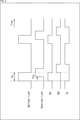
- the modulation method used in the indirect ToF method includes, for example, continuous wave modulation and pulse wave modulation.
- An example of the state of continuous wave modulation is shown in FIG.
- the sine wave 11 shows the emitted light (Emitted) and the sine wave 12 shows the reflected light (Reccived).
- the phase difference between the emitted light and the reflected light can be derived by performing lock-in detection using four time windows.
- the lock-in detection used here refers to an operation of accumulating signals of the same phase a plurality of times by a short electronic shutter synchronized with a light source.
- phase difference ⁇ TOF is given by the following equation (1) using the signals A 0 , A 1 , A 2 , A 3 accumulated in the four time windows TW 1, TW 2, TW 3, TW 4. As such, it is derived.
- the modulation frequency f m Since the modulation frequency f m is known, it can be converted from the phase ( ⁇ TOF ) to the time (t TOF ) using the following equation (2).
- the received light contains a DC component other than the light source, that is, a background light component, but the background light component is canceled by the calculation of the above equation (1). Therefore, in the range where the sensor is not saturated, the distance can be estimated without being affected by the background light.
- FIG. 3 shows an example of the state of pulse wave modulation.
- the flight time t TOF is derived as shown in the following equation (3).
- TD is a discharge window, and excess background light is discharged.
- the number of time windows TW is set to 3 or more, only the background light component can be known, and the distance can be estimated without being affected by the background light.
- pulse wave modulation by increasing the duty ratio of the light source, it is possible to realize robust imaging with respect to the background light.
- sensing data requires a wide dynamic range, but the required accuracy is not uniform.
- accuracy in mm units is required, but in the case of distances of several tens of meters, accuracy in cm units is sufficient.
- Such cases often have the same tendency with respect to intermediate data and intermediate processing of sensing data.
- the bit depth of the intermediate data generated from the sensing data obtained by the indirect TOF (Time-of-Flight) type sensor is corrected.
- the bit depth of the intermediate data generated from the sensing data obtained by the indirect TOF (Time-of-Flight) sensor is corrected, the intermediate data with the corrected bit depth is encoded, and the encoded data is generated. To do.
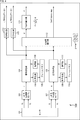
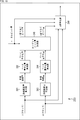
- FIG. 4 is a block diagram showing an example of a configuration of a distance measuring device, which is an aspect of an information processing device to which the present technology is applied.
- the distance measuring device 100 shown in FIG. 4 is a device that measures the distance to the subject by the indirect TOF method. It should be noted that FIG. 4 shows the main things such as the processing unit and the data flow, and not all of them are shown in FIG. That is, in the distance measuring device 100, there may be a processing unit that is not shown as a block in FIG. 4, or there may be a processing or data flow that is not shown as an arrow or the like in FIG.
- the distance measuring device 100 includes a sensor 101, an i signal generation unit 102, a signal processing unit 103, a coding unit 104, a frame memory 105, a decoding unit 106, a q signal generation unit 107, and a signal processing unit. It includes 108, a coding unit 109, a frame memory 110, a decoding unit 111, a phase difference detection unit 112, a depth calculation unit 113, a coding unit 114, and a coding unit 115.
- the sensor 101 is a sensor that detects light (reflected light) from the subject, which corresponds to the irradiation light emitted from the subject from a light source (not shown).
- the sensor 101 corresponds to the indirect TOF method as described with reference to, for example, FIGS. 2 and 3, and outputs signals A 0 to A 3 accumulated in the four time windows TW 1 to TW 4 as sensing data.
- the sensor 101 supplies the signal A 0 accumulated in the time window TW 1 and the signal A 2 accumulated in the time window TW 3 to the i signal generation unit 102 as sensing data. Further, the sensor 101 supplies the signal A 1 accumulated in the time window TW 2 and the signal A 3 accumulated in the time window TW 4 to the q signal generation unit 107 as sensing data.
- the i-signal generation unit 102 performs processing related to generation of the i-signal, which is intermediate data of the sensing data obtained by the sensor 101. For example, the i signal generation unit 102 acquires the signal A 0 and the signal A 2 supplied from the sensor 101. Further, the i-signal generation unit 102 derives the i-signal by calculating the difference (A 2 -A 0) between those signals. Further, the i-signal generation unit 102 supplies the derived i-signal to the signal processing unit 103.
- the signal processing unit 103 performs processing related to signal processing for the i signal. For example, the signal processing unit 103 acquires the i signal supplied from the i signal generation unit 102. Further, the signal processing unit 103 performs signal processing on the i signal. The content of this signal processing is arbitrary. The signal processing unit 103 may perform a plurality of signal processes, or may perform the same signal processing a plurality of times. Of course, signal processing can be omitted.
- the signal processing unit 103 stores the i signal, which is the signal processing target, in the frame memory 105 as needed. At that time, the signal processing unit 103 supplies the i signal to the coding unit 104 to encode it, and stores it in the frame memory 105 as coded data.
- the signal processing unit 103 reads out the i signal stored in the frame memory 105 as needed. At that time, the signal processing unit 103 acquires the i signal obtained by decoding the coded data read from the frame memory 105 by the decoding unit 106.
- writing and reading to the frame memory 105 may be performed at any timing. For example, this writing or reading may be performed before, after, or during the signal processing by the signal processing unit 103. Moreover, this writing and reading may be repeated a plurality of times. For example, this writing or reading may be performed before, during, or after the signal processing.
- the signal processing unit 103 supplies the i signal that has been appropriately signal-processed to the phase difference detection unit 112.
- the signal processing unit 103 can also supply the i signal to the coding unit 114.
- the coding unit 104 performs processing related to coding the i signal. For example, the coding unit 104 encodes the i signal supplied from the signal processing unit 103 and generates the coded data. Then, the coding unit 104 supplies the coded data of the generated i signal to the frame memory 105. That is, the coding unit 104 performs processing related to coding of the i signal stored in the frame memory 105.
- the coding unit 104 By encoding the i-signal by the coding unit 104 in this way, it is possible to suppress an increase in the amount of i-signal data stored in the frame memory 105. That is, it is possible to suppress an increase in the load of the frame memory 105 (the storage capacity used for storing the i signal), and it is possible to improve the utilization efficiency of the frame memory 105. In other words, it is possible to suppress an increase in the storage capacity required for the frame memory 105, and it is possible to suppress an increase in the manufacturing cost and power consumption of the frame memory 105.
- the frame memory 105 has an arbitrary storage medium such as a semiconductor memory, and performs processing related to i-signal storage. For example, the frame memory 105 acquires the coded data of the i signal supplied from the coding unit 104 and stores it in the storage medium. Further, the frame memory 105 reads out the i signal (encoded data) stored in the storage medium and supplies the i signal (encoded data) to the decoding unit 106. That is, the frame memory 105 stores the signal processing target (i signal) of the signal processing unit 103.
- the storage medium may be any kind, for example, a flash memory or a hard disk, or a removable removable medium.
- the decoding unit 106 performs processing related to decoding the coded data of the i signal. For example, the decoding unit 106 decodes the coded data supplied from the frame memory 105 and generates an i signal. Then, the decoding unit 106 supplies the generated i signal to the signal processing unit 103. That is, the decoding unit 106 performs processing related to decoding the i signal stored in the frame memory 105.
- the signal processing unit 103 can process the i signal read from the frame memory 105 in an unencoded plane state. That is, the target of signal processing (i signal) by the signal processing unit 103 can be encoded and stored as described above. Therefore, the above-mentioned effect can be obtained for the frame memory 105 that stores the signal processing target (i signal) of the signal processing unit 103.
- the q signal generation unit 107 performs processing related to generation of the q signal, which is intermediate data of the sensing data obtained by the sensor 101. For example, the q signal generation unit 107 acquires the signal A 1 and the signal A 3 supplied from the sensor 101. Further, the q signal generation unit 107 derives the q signal by calculating the difference between those signals (A 3 -A 1). Further, the q signal generation unit 107 supplies the derived q signal to the signal processing unit 108.
- the signal processing unit 108, the coding unit 109, the frame memory 110, and the decoding unit 111 have the same configurations as the signal processing unit 103, the coding unit 104, the frame memory 105, and the decoding unit 106, respectively, and have the same configurations. The same effect can be obtained by performing the processing.
- each processing unit of the signal processing unit 108 to the decoding unit 111 processes the q signal instead of the i signal. That is, the signal processing unit 108 performs processing related to signal processing for the q signal.
- the coding unit 109 performs processing related to coding of the q signal stored in the frame memory 110.
- the frame memory 110 stores a signal processing target (q signal) of the signal processing unit 108.
- the decoding unit 111 performs a process related to decoding the q signal stored in the frame memory 110.
- the phase difference detection unit 112 performs processing related to detection of the phase difference between the light emitting signal and the received signal. For example, the phase difference detection unit 112 acquires the i signal supplied from the signal processing unit 103. Further, the phase difference detection unit 112 acquires the q signal supplied from the signal processing unit 108. Further, the phase difference detection unit 112 performs the calculation of the above-mentioned equation (1) using the acquired i signal and q signal, and calculates the phase difference ⁇ TOF between the light emission signal and the received signal.
- the phase difference detection unit 112 can output the calculated phase difference ⁇ TOF to the outside of the ranging device 100.
- the phase difference detection unit 112 can calculate the phase difference ⁇ TOF for each pixel or each partial region and output it as map information of the phase difference ⁇ TOF to the outside of the distance measuring device 100.
- the phase difference detection unit 112 can output the map information of the phase difference ⁇ TOF to the outside of the distance measuring device 100 as reliability map information (Confidence map).
- phase difference detection unit 112 can supply the calculated phase difference ⁇ TOF to the depth calculation unit 113.
- the Depth calculation unit 113 performs processing related to the calculation of the depth value. For example, the depth calculation unit 113 can acquire the phase difference ⁇ TOF between the light emitting signal and the received signal supplied from the phase difference detecting unit 112. Further, the depth calculation unit 113 can estimate the distance (that is, the depth value) d to the subject by performing the calculation of the following equation (4) using the acquired phase difference ⁇ TOF.
- the depth calculation unit 113 can output the depth value d calculated as described above to the outside of the distance measuring device 100.
- the depth calculation unit 113 can calculate the depth value d as described above for each pixel or each partial area and output it as map information (depth image) to the outside of the distance measuring device 100.
- the coding unit 114 performs processing related to coding the i signal, similarly to the coding unit 104. That is, the coding unit 114 has the same configuration as the coding unit 104, and performs the same processing. That is, the coding unit 114 encodes the i signal supplied from the signal processing unit 103 and generates the coded data. However, the coding unit 114 outputs the coded data of the generated i signal to the outside of the distance measuring device 100. That is, the coding unit 114 performs processing related to coding of the i signal to be output to the outside of the distance measuring device 100.
- the ranging device 100 can output the i signal which is intermediate data. Then, when the coding unit 114 encodes the i signal, the distance measuring device 100 can encode and output the i signal. By doing so, it is possible to suppress an increase in the transmission band used for transmitting the output i signal and the storage capacity required for storing the output i signal. Therefore, the increase in cost can be suppressed.
- the coding unit 115 has the same configuration as the coding unit 114, performs the same processing, and can obtain the same effect. However, the coding unit 115 processes the q signal instead of the i signal. That is, the coding unit 115 encodes the q signal supplied from the signal processing unit 108 and generates the coded data. Then, the coding unit 115 outputs the coded data of the generated q signal to the outside of the distance measuring device 100. That is, the coding unit 115 performs processing related to coding of the q signal to be output to the outside of the distance measuring device 100.
- the ranging device 100 can output the q signal which is the intermediate data. Then, when the coding unit 115 encodes the q signal, the distance measuring device 100 can encode and output the q signal. By doing so, it is possible to suppress an increase in the transmission band used for transmitting the output q signal and the storage capacity required for storing the output q signal. Therefore, the increase in cost can be suppressed.
- the i signal and the q signal are processed independently of each other.
- the configuration of the ranging device 100 is arbitrary and is not limited to the above-mentioned example.
- the i signal generation unit 102 and the q signal generation unit 107 may be integrated into one signal generation unit.
- the signal processing unit 103 and the signal processing unit 108 may be integrated into one signal processing unit.
- the coding unit 104 and the coding unit 109 may be integrated into one coding unit.
- the frame memory 105 and the frame memory 110 may be integrated into one frame memory.
- the decoding unit 106 and the decoding unit 111 may be integrated into one decoding unit 111.
- the processing unit that processes the i signal and the processing unit that processes the q signal are integrated, the i signal and the q signal are processed independently of each other.
- the i signal and the q signal may be processed independently of each other by time division, or two input / outputs may be provided.
- each processing unit may be configured by a logic circuit that realizes the above-mentioned processing.
- each processing unit has, for example, a CPU (Central Processing Unit), a ROM (Read Only Memory), a RAM (Random Access Memory), and the like, and the above-mentioned processing is realized by executing a program using them. You may do so.
- each processing unit may have both configurations, and a part of the above-mentioned processing may be realized by a logic circuit, and the other may be realized by executing a program.
- the configurations of the respective processing units may be independent of each other. For example, some processing units realize a part of the above-mentioned processing by a logic circuit, and some other processing units execute a program.
- the above-mentioned processing may be realized by the other processing unit by both the logic circuit and the execution of the program.
- FIG. 5 is a block diagram showing a main configuration example of the coding unit 104 of FIG. It should be noted that FIG. 5 shows the main things such as the processing unit and the data flow, and not all of them are shown in FIG. That is, in the coding unit 104, there may be a processing unit that is not shown as a block in FIG. 5, or there may be a processing or data flow that is not shown as an arrow or the like in FIG.
- the coding unit 104 includes a sensing gamma correction unit 131 and a coding unit 132.
- the sensing gamma correction unit 131 performs processing related to correction of the bit depth of the input data. For example, the sensing gamma correction unit 131 acquires the i signal, which is intermediate data of the sensing data, as input data from the outside of the coding unit 104 (for example, the signal processing unit 103). Further, the sensing gamma correction unit 131 corrects the bit depth of the i signal. At that time, the sensing gamma correction unit 131 corrects the bit depth of the i signal (gamma correction is performed) by using the gamma curve which is a predetermined curve showing the input / output characteristics.
- the sensing gamma correction unit 131 reduces the bit depth of the i signal at a compression rate corresponding to the gamma curve. Further, the sensing gamma correction unit 131 supplies the i signal after bit depth correction (after gamma correction) to the coding unit 132.
- the coding unit 132 performs processing related to coding the i signal. For example, the coding unit 132 acquires the gamma-corrected i signal supplied from the sensing gamma correction unit 131, encodes it, and generates coded data. This coding method is arbitrary. For example, an existing image coding method may be used. The coding unit 132 supplies the coded data of the generated i signal to the outside of the coding unit 104 (for example, the frame memory 105).
- the sensing gamma correction unit 131 corrects so as to reduce the bit depth of the i signal
- the coding unit 104 suppresses the reduction of the coding efficiency of the sensing data (the i signal which is the intermediate data). be able to. Therefore, the ranging device 100 can suppress an increase in the processing load of the sensing data as described above.
- the coding unit 109 also has the same configuration as the coding unit 104. That is, the configuration example shown in FIG. 5 can also be applied to the coding unit 109. However, in the case of the coding unit 109, the processing target is the q signal.
- the coding unit 114 also has the same configuration as the coding unit 104. That is, the configuration example shown in FIG. 5 can also be applied to the coding unit 114. However, in the case of the coding unit 114, the coded data of the i signal generated by the coding unit 132 is output to the outside of the distance measuring device 100.
- the coding unit 115 also has the same configuration as the coding unit 104. That is, the configuration example shown in FIG. 5 can also be applied to the coding unit 115. However, in the case of the coding unit 115, the processing target is the q signal, and the coded data of the q signal generated by the coding unit 132 is output to the outside of the distance measuring device 100.
- the sensing gamma correction unit 131 can correct the bit depth of the i signal and the bit depth of the q signal independently of each other.
- the coding unit 132 can encode the i signal and the q signal whose bit depth is corrected independently of each other, and can generate the coded data of the i signal and the coded data of the q signal, respectively. ..
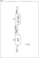
- FIG. 6 is a block diagram showing a main configuration example of the decoding unit 106 of FIG. Note that FIG. 6 shows the main things such as the processing unit and the data flow, and not all of them are shown in FIG. That is, in the decoding unit 106, there may be a processing unit that is not shown as a block in FIG. 6, or there may be a processing or data flow that is not shown as an arrow or the like in FIG.
- the decoding unit 106 has a decoding unit 151 and a sensing inverse gamma correction unit 152.
- the decoding unit 151 performs processing related to decoding the coded data of the i signal. For example, the decoding unit 151 acquires the coded data of the i signal read from the outside of the decoding unit 106 (for example, the frame memory 105). Further, the decoding unit 151 decodes the encoded data and generates an i signal (reconstruction data before reverse gamma correction).
- This decoding method is arbitrary as long as it corresponds to the coding method applied by the coding unit 132. For example, an existing image decoding method may be used. That is, the decoding unit 151 performs the reverse processing of the coding unit 132. Further, the decoding unit 151 supplies the generated i signal (reconstruction data before the reverse gamma correction) to the sensing reverse gamma correction unit 152.
- the sensing reverse gamma correction unit 152 performs processing related to reverse correction of the bit depth of the i signal. For example, the sensing inverse gamma correction unit 152 acquires the i signal (reconstruction data before the inverse gamma correction) supplied from the decoding unit 151. Further, the sensing reverse gamma correction unit 152 reversely corrects the bit depth of the i signal (reconstructed data before the reverse gamma correction). At that time, the sensing inverse gamma correction unit 152 reverse-corrects the bit depth of the i signal (performs the inverse gamma correction) by using the inverse gamma curve which is a predetermined curve showing the input / output characteristics.
- This inverse gamma curve is the inverse function of the gamma curve used by the sensing gamma correction unit 131. That is, this reverse gamma correction is the reverse processing of the gamma correction by the sensing gamma correction unit 131.
- the sensing inverse gamma correction unit 152 restores the bit depth of the i signal reduced by the compression rate according to the gamma curve at the expansion rate corresponding to the inverse gamma curve. That is, it returns to the bit depth before reduction.
- the sensing inverse gamma correction unit 152 supplies the i signal (reconstructed data) whose bit depth is restored to the outside of the decoding unit 106 (for example, the signal processing unit 103).
- the sensing inverse gamma correction unit 152 corrects so as to restore the bit depth of the i signal, so that the decoding unit 106 can return the sensing data (the i signal which is the intermediate data) to the original bit depth. can. That is, the decoding unit 106 can suppress the reduction of the coding efficiency of the sensing data (i signal which is the intermediate data). Therefore, the ranging device 100 can suppress an increase in the processing load of the sensing data as described above.
- the decoding unit 111 also has the same configuration as the decoding unit 106. That is, the configuration example shown in FIG. 6 can also be applied to the decoding unit 111. However, in the case of the decoding unit 111, the processing target is the q signal.
- the decoding unit 151 can decode the coded data of the i signal and the coded data of the q signal independently of each other to generate the i signal and the q signal, respectively.
- the sensing inverse gamma correction unit 152 can reverse-correct (that is, return to the original bit depth) the bit depth of the i signal and the bit depth of the q signal independently of each other.
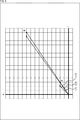
- FIG. 7 An example of the above-mentioned gamma curve and inverse gamma curve is shown in FIG.
- the gamma curve 161 and the inverse gamma curve 162 shown in FIG. 7 are inverse functions of each other. That is, the correction of the bit depth by the sensing gamma correction unit 131 and the reverse correction of the bit depth by the sensing reverse gamma correction unit 152 are reversible processes and are opposite processes to each other. That is, the original signal value can be restored by performing this correction and the reverse correction on the i signal and the q signal.
- the gamma curve and the inverse gamma curve may be designed based on the calculation accuracy required in the subsequent processing. That is, the sensing gamma correction unit 131 may correct the bit depth of the i signal or the q signal by using the gamma curve designed based on the calculation accuracy required in the subsequent processing. Further, the sensing inverse gamma correction unit 152 may reverse-correct the bit depth of the i signal or the q signal by using the inverse gamma curve designed based on the calculation accuracy required in the post-stage processing.
- iToF detects the phase difference between the light emission signal and the received signal by using arctan using the i signal and q signal, and converts the phase signal into depth information (depth data).
- a signal having a small L2 norm and close to the origin is defined as A
- a signal having a large L2 norm and far from the origin is defined as B.
- the phase difference between the signal A and the signal B before noise superimposition is represented by an angle 171. Due to noise superposition, the phase difference of the signal B corresponds to the angle 172, and the phase difference of the signal A corresponds to the angle 173. That is, as can be seen by looking at the values after each noise superposition, in iToF, pixel values with a small L2 norm are sensitive to deterioration, and as the L2 norm increases, the effect of deterioration decreases.
- the accuracy of the data required for the i signal and q signal varies depending on the absolute value of the value of the i signal and q signal, and when the absolute value is small, high accuracy is required, and the absolute value is required.
- the absolute value is small, high accuracy is required, and the absolute value is required.
- holding data with uniform accuracy regardless of the magnitude of the absolute value has redundant accuracy in holding data, which causes an increase in cost.
- the sensing gamma correction unit 131 corrects (reduces) the bit depth of the i signal and the q signal using the gamma curve as described above
- the sensing inverse gamma correction unit 152 corrects (reduces) the bit depth of the i signal and the q signal as described above.
- quantized values (quant i , quant q ) applicable to i and q when the accuracy of the phase ⁇ is kept constant are the absolute values as shown in the following equations (11) and (12). It can be obtained by scaling to.
- the gamma curve is derived using the quantization value derived as described above.
- the gamma curve to be obtained as a curve that can be quantized by the above formula. As shown in the curve 181 shown in FIG. 10, the slope of the gamma curve to be obtained can be calculated from the reciprocal of the minimum quantization value.
- A which is a parameter of the minimum quantization value, is a parameter for adjusting according to the desired accuracy and the desired compression rate.
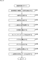
- the sensor 101 of the distance measuring device 100 detects the signals (for example, signals A 0 to A 3 ) accumulated in each time window in step S101.
- step S102 the i-signal generation unit 102 generates an i-signal using the signal detected in step S101 (for example, A 2- A 0 ).
- step S103 the q signal generation unit 107 generates a q signal using the signal detected in step S101 (for example, A 3 -A 1 ).
- step S104 the signal processing unit 103 to the decoding unit 106 execute i-signal processing and process the i-signal generated in step S102.
- step S105 the signal processing unit 108 to the decoding unit 111 execute q signal processing, and signal process the q signal generated in step S103.
- step S106 the phase difference detection unit 112 uses the i signal that has been appropriately signal-processed in step S104 and the q signal that has been appropriately signal-processed in step S105, and has a phase difference between the light emission signal and the received signal. Is detected.
- step S107 the phase difference detection unit 112 generates a confidence map based on the phase difference detected in step S106 and outputs it to the outside of the distance measuring device 100.
- the output of the confidence map can be omitted. In that case, this process can be omitted.
- step S108 the depth calculation unit 113 calculates the depth value using the phase difference detected in step S106.
- step S109 the depth calculation unit 113 outputs the depth value as depth data to the outside of the distance measuring device 100.
- the output of depth data can be omitted. In that case, these processes can be omitted.
- step S110 the coding unit 114 executes the i-signal coding process and generates the i-signal coding data. Further, in step S111, the coding unit 115 executes the q signal coding process and generates the q signal coding data. Further, in step S112, the coding unit 114 outputs the coded data of the i signal generated in step S110 to the outside of the distance measuring device 100. Similarly, in step S113, the coding unit 115 outputs the coded data of the q signal generated in step S111 to the outside of the distance measuring device 100.
- the output of the coded data of the i signal and the q signal can be omitted. In that case, these processes can be omitted.
- step S113 When the process of step S113 is completed, the distance measurement process is completed.
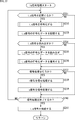
- step S104 the signal processing unit 103 determines in step S131 whether or not to store the i-signal. If it is determined that the i signal is stored, the process proceeds to step S132.
- step S132 the coding unit 104 executes the i-signal coding process, encodes the i-signal, and generates coded data.
- step S133 the frame memory 105 stores the coded data of the i signal generated in step S132.
- step S134 the process proceeds to step S134. If it is determined in step S131 that the i signal is not stored, the process proceeds to step S134.
- step S134 the signal processing unit 103 determines whether or not to read the i signal. If it is determined to read the i signal, the process proceeds to step S135. In step S135, the frame memory 105 reads out the coded data of the requested i signal. In step S136, the decoding unit 106 executes the i-signal decoding process, decodes the coded data of the i-signal, and generates the i-signal. When the process of step S136 is completed, the process proceeds to step S137. If it is determined in step S134 that the i signal is not read, the process proceeds to step S137.
- step S137 the signal processing unit 103 determines whether or not to perform signal processing on the i signal. If it is determined that the signal processing is to be performed, the processing proceeds to step S138. In step S138, the signal processing unit 103 processes the i signal. When the process of step S138 is completed, the process proceeds to step S139. If it is determined in step S137 that signal processing is not performed, the processing proceeds to step S139.
- step S139 the signal processing unit 103 determines whether or not to end the signal processing. When it is determined that the signal processing is not completed due to the existence of unprocessed data or unexecuted signal processing, the processing returns to step S131, and the subsequent processing is repeated. Further, in step S139, when it is determined that the signal processing is completed by performing all the processing or the like, the processing proceeds to step S140.
- step S140 the signal processing unit 103 supplies the i-signal that has undergone signal processing as appropriate to the phase difference detection unit 112.
- the processing in step S140 is completed, the i-signal processing is completed, and the processing returns to FIG.
- the processing order of the processing groups of steps S131 to S133, the processing groups of steps S134 to S136, and the processing groups of steps S137 and S138 is arbitrary, and is shown in the example of FIG. Not limited.
- the processes of steps S137 and S138 may be performed, and then the processes of steps S131 to S133 and the processes of steps S134 to S136 may be performed.
- it may be in any other order. That is, the i signal can be written or read at any timing of signal processing.
- the sensing gamma correction unit 131 of the coding unit 104 gamma-corrects the bit depth of the i-signal using the gamma curve designed as described above in step S161.
- step S162 the coding unit 132 encodes the gamma-corrected i-signal in step S161 and generates the coded data of the i-signal.
- the i-signal coding process is completed, and the process returns to FIG.
- the decoding unit 151 of the decoding unit 106 decodes the coded data of the i-signal in step S181 and generates the i-signal before the inverse gamma correction.
- step S182 the sensing inverse gamma correction unit 152 reverse gamma corrects the bit depth of the i signal generated in step S181 using the inverse gamma curve designed as described above, and corrects the i signal before gamma correction. Restore.
- step S182 the process of step S182 is completed, the i-signal decoding process is completed, and the process returns to FIG.
- the ranging device 100 can suppress an increase in the processing load of the sensing data.
- the i-signal coding process executed by the coding unit 114 in step S110 of the distance measuring process of FIG. 12 may be performed in the same flow as the i-signal coding process described with reference to the flowchart of FIG. can. That is, the description with reference to the flowchart of FIG. 14 can also be applied to the i-signal coding process of step S110.
- the q signal processing executed by the signal processing unit 108 to the decoding unit 111 in step S105 of the distance measuring process of FIG. 12 may be performed in the same flow as the i signal processing described with reference to the flowchart of FIG. can. That is, the description with reference to the flowchart of FIG. 13 can also be applied to the q signal processing in step S105.
- the q signal is processed instead of the i signal.
- the q signal coding process for encoding the q signal is executed instead of the i signal coding process.
- This q signal coding process can be performed in the same flow as the i signal coding process described with reference to the flowchart of FIG. That is, the description with reference to the flowchart of FIG. 14 can also be applied to this q signal coding process.
- the q signal is processed instead of the i signal.
- the q signal decoding process for decoding the encoded data of the q signal is executed instead of the i signal decoding process.
- This q signal decoding process can be performed in the same flow as the i signal decoding process described with reference to the flowchart of FIG. That is, the description with reference to the flowchart of FIG. 15 can also be applied to this q signal decoding process. However, in this case, the q signal is processed instead of the i signal.
- the q signal coding process executed by the coding unit 115 in the distance measuring process step S111 of FIG. 12 is performed in the same flow as the q signal coding process executed in the q signal processing step S132 described above. be able to. That is, the description with reference to the flowchart of FIG. 14 can also be applied to the q signal coding process in step S111. However, in this case, the q signal is processed instead of the i signal.
- Second Embodiment> ⁇ Distance measuring device>
- the i signal and the q signal which are the intermediate data of the sensing data
- the present invention is not limited to this, and the intermediate data of the sensing data is the i signal and the q. It may be processed as multidimensional vector data including both signals. That is, the i signal and the q signal may be combined into one signal for processing.
- FIG. 16 is a block diagram showing an example of the configuration of a distance measuring device, which is an aspect of an information processing device to which the present technology is applied.
- the distance measuring device 200 shown in FIG. 16 is a device that measures the distance to the subject by the indirect TOF method, like the distance measuring device 100.
- the intermediate data of the sensing data is processed as multidimensional vector data including both the i signal and the q signal.
- FIG. 16 shows the main things such as the processing unit and the data flow, and not all of them are shown in FIG. That is, in the distance measuring device 200, there may be a processing unit that is not shown as a block in FIG. 16, or there may be a processing or data flow that is not shown as an arrow or the like in FIG.
- the distance measuring device 200 basically has the same configuration as the distance measuring device 100. However, the distance measuring device 200 has a coding unit 201 to a frame memory 202, and a decoding unit 203 instead of the coding unit 104 to the decoding unit 106 and the coding unit 109 to the decoding unit 111.
- the distance measuring device 200 has a coding unit 204 instead of the coding unit 114 and the coding unit 115.
- the coding unit 201 performs processing related to coding of the i signal and the q signal. For example, the coding unit 201 acquires the i signal supplied from the signal processing unit 103 and the q signal supplied from the signal processing unit 108. Further, the coding unit 201 encodes the multidimensional vector data including those signals and generates the coded data. Then, the coding unit 201 supplies the generated coded data (encoded data corresponding to the i signal and the q signal) to the frame memory 202. That is, the coding unit 201 performs processing related to coding of multidimensional vector data including the i signal and the q signal stored in the frame memory 202.
- the coding unit 201 can obtain the same effect as the coding unit 104 and the coding unit 109.
- the frame memory 202 has a storage medium similar to the frame memory 105 and the frame memory 110, and performs processing related to storage of the i signal and the q signal. For example, the frame memory 202 acquires the coded data supplied from the coding unit 201 and stores it in the storage medium thereof. Further, the frame memory 202 reads out the coded data stored in the storage medium and supplies the coded data to the decoding unit 203. That is, the frame memory 202 stores the signal processing targets (i signal and q signal) of the signal processing unit 103 and the signal processing unit 108.
- the storage medium may be any kind, for example, a flash memory or a hard disk, or a removable removable medium.
- the frame memory 202 can obtain the same effect as the frame memory 105 and the frame memory 110.
- the decoding unit 203 performs processing related to decoding of the coded data of the i signal and the q signal. For example, the decoding unit 203 decodes the encoded data of the multidimensional vector data including the i signal and the q signal supplied from the frame memory 202 to generate the i signal and the q signal. Then, the decoding unit 203 supplies the generated i signal to the signal processing unit 103, and supplies the generated q signal to the signal processing unit 108. That is, the decoding unit 203 performs processing related to decoding of the multidimensional vector data including the i signal and the q signal stored in the frame memory 202.
- the decoding unit 203 can obtain the same effect as the decoding unit 106 and the decoding unit 111.
- the coding unit 204 performs processing related to coding of the i signal and the q signal, similarly to the coding unit 201. That is, the coding unit 204 has the same configuration as the coding unit 201, and performs the same processing. That is, the coding unit 204 encodes the multidimensional vector data including the i signal supplied from the signal processing unit 103 and the q signal supplied from the signal processing unit 108, and generates the coded data. However, the coding unit 204 outputs the generated coded data to the outside of the distance measuring device 200. That is, the coding unit 204 performs processing related to coding of multidimensional vector data including the i signal and the q signal to be output to the outside of the distance measuring device 200.
- the coding unit 204 can obtain the same effect as the coding unit 114 and the coding unit 115.
- the ranging device 200 can suppress an increase in the processing load of sensing data.
- each processing unit may be configured by a logic circuit that realizes the above-mentioned processing.
- each processing unit may have, for example, a CPU, ROM, RAM, etc., and execute a program using them to realize the above-mentioned processing.
- each processing unit may have both configurations, and a part of the above-mentioned processing may be realized by a logic circuit, and the other may be realized by executing a program.
- the configurations of the respective processing units may be independent of each other. For example, some processing units realize a part of the above-mentioned processing by a logic circuit, and some other processing units execute a program.
- the above-mentioned processing may be realized by the other processing unit by both the logic circuit and the execution of the program.
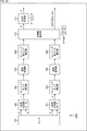
- FIG. 17 is a block diagram showing a main configuration example of the coding unit 201. It should be noted that FIG. 17 shows the main things such as the processing unit and the data flow, and not all of them are shown in FIG. That is, in the coding unit 201, there may be a processing unit that is not shown as a block in FIG. 17, or there may be a processing or data flow that is not shown as an arrow or the like in FIG.
- the coding unit 201 has a block dividing unit 221, a block dividing unit 222, a joint coding unit 223, and a buffer 224.
- the block division unit 221 acquires the i signal supplied from the signal processing unit 103, divides it into predetermined block units, and supplies it to the joint coding unit 223. That is, the i signal is divided by the block division unit 221 according to the input size to the joint coding unit 223.
- the block division unit 222 acquires the q signal supplied from the signal processing unit 108, divides it into predetermined block units, and supplies the q signal to the joint coding unit 223. That is, the q signal is divided by the block division unit 222 according to the input size to the joint coding unit 223.
- the joint coding unit 223 performs processing related to coding of the i signal and the q signal supplied in block units. For example, the joint coding unit 223 acquires the i-signal in block units supplied from the block dividing unit 221. Further, the joint coding unit 223 acquires a block-based q signal supplied from the block dividing unit 222. Further, the joint coding unit 223 acquires information for designating the total bit amount (total bit amount of the i signal and the q signal).
- the joint coding unit 223 encodes the acquired block-shaped i signal and q signal so as to match the total bit amount specified from the outside, and generates one bit stream (encoded data). ..
- the joint coding unit 223 supplies the generated coded data to the buffer 224.
- the buffer 224 temporarily holds the coded data supplied from the joint coding unit 223, smoothes the bit rate, and outputs the data. Note that, for example, if the joint coding unit 223 can generate coded data so that the bit rate exactly matches the specified total bit amount, the buffer 224 may be omitted.
- the coding unit 204 also has the same configuration as the coding unit 201. That is, the configuration example shown in FIG. 17 can also be applied to the coding unit 204. However, in the case of the coding unit 204, the coded data output from the buffer 224 is output to the outside of the distance measuring device 200.
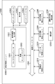
- FIG. 18 is a block diagram showing a main configuration example of the joint coding unit 223. Note that FIG. 18 shows the main things such as the processing unit and the data flow, and not all of them are shown in FIG. That is, in this joint coding unit 223, there may be a processing unit that is not shown as a block in FIG. 18, or there may be a processing or data flow that is not shown as an arrow or the like in FIG.
- the joint coding unit 223 includes a tolerance amount calculation unit 241, a base quantization amount calculation unit 242, a tolerance amount calculation unit 243, a base quantization amount calculation unit 244, and a target bit amount determination unit. It has 245 and an iq coding unit 246.
- the permissible error amount calculation unit 241 calculates the permissible error amount (also referred to as the permissible error amount) for the supplied i signal.
- the permissible error amount calculation unit 241 supplies the calculated permissible error amount of the i signal to the base quantization amount calculation unit 242.
- the base quantization amount calculation unit 242 calculates the base quantization amount of each pixel based on the supplied margin of error amount. For example, the base quantization amount calculation unit 242 calculates the base quantization amount base q step by rounding down the allowable error amount to a predetermined value or less by using the floor function as shown in the following equation (14).
- the base quantization amount calculation unit 242 supplies the calculated base quantization amount for the i signal to the target bit amount determination unit 245.
- the permissible error amount calculation unit 243 performs the same processing as the permissible error amount calculation unit 241 on the supplied q signal.
- the base quantization amount calculation unit 244 performs the same processing as the base quantization amount calculation unit 242, calculates the base quantization amount for the q signal, and supplies it to the target bit amount determination unit 245.
- the target bit amount determining unit 245 sets the i signal as the target bit amount based on the base quantization amount for each of the i signal and the q signal supplied in this way and the total bit amount specified from the outside. Determine the amount of allocated bits and the amount of allocated bits for the q signal.
- the target bit amount determination unit 245 supplies the determined information indicating the allocated bit amount of the i signal and the information indicating the allocated bit amount of the q signal to the iq coding unit 246.
- the target bit amount determination unit 245 calculates the effective bit depth vd of each of the i signal and the q signal, as shown in FIG.
- the effective bit depth vd is calculated using the following equations (15) and (16).
- the iq coding unit 246 acquires the i signal and the q signal for each block supplied to the joint coding unit 223, respectively. Further, the iq coding unit 246 sets the i signal and the i signal based on the i signal allocation bit amount and the q signal allocation bit amount determined by the target bit amount determination unit 245, and the total bit amount specified from the outside. Each of the bit depths of the q signal is corrected, and they are combined and encoded as one data to generate encoded data. The iq coding unit 246 supplies the generated coded data to the buffer 224.
- the configuration of this iq coding unit 246 is arbitrary.
- the iq coding unit 246 may have the same configuration as the coding unit 104 (FIG. 5).
- the intermediate data of the sensing data to be coded is set as multidimensional vector data including both the i signal and the q signal. That is, the sensing gamma correction unit 131 corrects the bit depth of the multidimensional vector data including both the i signal and the q signal, and the coding unit 132 encodes the multidimensional vector data whose bit depth has been corrected. Generate coded data.
- the bit depth correction at that time is based on the i-signal allocation bit amount and q-signal allocation bit amount determined by the target bit amount determination unit 245, and the total bit amount specified from the outside. Do it.
- FIG. 20 is a block diagram showing a main configuration example of the decoding unit 203. It should be noted that FIG. 20 shows the main things such as the processing unit and the data flow, and not all of them are shown in FIG. 20. That is, in the decoding unit 203, there may be a processing unit that is not shown as a block in FIG. 20, or there may be a processing or data flow that is not shown as an arrow or the like in FIG. 20.
- the decoding unit 203 has a buffer 281, a joint decoding unit 282, a block coupling unit 283, and a block coupling unit 284.
- the buffer 281 holds the coded data read from the frame memory 202, smoothes the bit rate, and supplies the coded data to the joint decoding unit 282. When the bit rate of the coded data is smoothed and supplied to the decoding unit 203, the buffer 281 may be omitted.
- the joint decoding unit 282 decodes the encoded data, and based on the total bit amount specified from the outside, the allocated bit amount of the i signal, the allocated bit amount of the q signal, and the like from the decoded data, i for each block. Extract the signal and q signal.
- the joint decoding unit 282 supplies the extracted i signal to the block coupling unit 283. Further, the joint decoding unit 282 supplies the extracted q signal to the block coupling unit 284.
- the block coupling unit 283 combines the i signals for each supplied block, and supplies the combined i signals to the signal processing unit 103. Further, the block coupling unit 284 combines the q signals for each supplied block, and supplies the combined q signals to the signal processing unit 108.
- the decoding unit 203 performs the reverse processing of the coding unit 201.
- step S204 the signal processing unit 103, the signal processing unit 108, and the coding unit 201 to the decoding unit 203 execute iq signal processing, and the i signal generated in step S202 and the q generated in step S203 Signal processing both with the signal.
- step S209 the coding unit 204 executes the iq signal coding process to generate the coded data of the multidimensional vector data including both the i signal and the q signal. Then, in step S210, the coding unit 204 outputs the coded data generated in step S209 to the outside of the distance measuring device 200. The output of this coded data can be omitted. In that case, these processes can be omitted.
- step S210 When the process of step S210 is completed, the distance measurement process is completed.
- step S204 of FIG. 21 ⁇ Flow of iq signal processing>
- the signal processing unit 103 and the signal processing unit 108 determine in step S231 whether or not to store the i signal and the q signal. If it is determined that the i signal and the q signal are stored, the process proceeds to step S232.
- the coding unit 201 executes the iq signal coding process, encodes the i signal and the q signal, and generates coded data.
- step S233 the frame memory 202 stores the encoded data of the multidimensional vector data including both the i signal and the q signal generated in step S232.
- step S234 the process proceeds to step S234. If it is determined in step S231 that the i signal and the q signal are not stored, the process proceeds to step S234.
- step S234 the signal processing unit 103 and the signal processing unit 108 determine whether or not to read the i signal and the q signal. If it is determined to read the i signal and the q signal, the process proceeds to step S235.
- step S235 the frame memory 202 reads the encoded data of the multidimensional vector data including both the requested i signal and the q signal.
- step S236 the decoding unit 203 executes the iq signal decoding process, decodes the encoded data, and generates the i signal and the q signal.
- step S236 proceeds to step S237. If it is determined in step S234 that the i signal and the q signal are not read, the process proceeds to step S237.
- step S237 the signal processing unit 103 and the signal processing unit 108 determine whether or not to perform signal processing on the i signal and the q signal. If it is determined that the signal processing is to be performed, the processing proceeds to step S238. In step S238, the signal processing unit 103 processes the i signal. In step S239, the signal processing unit 108 signals the q signal. When the process of step S239 is completed, the process proceeds to step S240. If it is determined in step S237 that signal processing is not performed, the processing proceeds to step S240.
- step S240 the signal processing unit 103 and the signal processing unit 108 determine whether or not to end the signal processing. When it is determined that the signal processing is not completed due to the existence of unprocessed data or unexecuted signal processing, the processing returns to step S231 and the subsequent processing is repeated. Further, in step S240, when it is determined that the signal processing is completed by performing all the processing or the like, the processing proceeds to step S241.
- step S241 the signal processing unit 103 supplies the i signal that has been appropriately processed to the phase difference detection unit 112, and the signal processing unit 108 supplies the q signal that has been appropriately processed to the phase difference detection unit 112. do.
- step S241 the processing of step S241 is completed, the iq signal processing is completed, and the processing returns to FIG.
- the processing order of the processing group of steps S231 to S233, the processing group of steps S234 to S236, and the processing group of steps S237 to S239 is arbitrary, and the example of FIG. 22 shows. Not limited.
- the processes of steps S237 to S239 may be performed, and then the processes of steps S231 to S233 and the processes of steps S234 to S236 may be performed.
- it may be in any other order. That is, the writing and reading of the i signal and the q signal can be performed at any timing of signal processing.
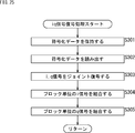
- the block dividing unit 221 of the coding unit 201 divides the i signal into block units in step S261.
- the block division unit 222 divides the q signal into block units.
- step S263 the joint coding unit 223 executes the joint coding process, joint-codes the i signal and the q signal based on the specified total bit amount, and multidimensionally includes both the i signal and the q signal. Generate coded data for vector data.
- step S264 the buffer 224 holds the coded data generated in step S263.
- step S265 the buffer 224 reads the coded data so that the bit rate is smoothed, and outputs the coded data to the outside of the distance measuring device 200.
- the permissible error amount calculation unit 241 calculates the permissible error amount of the i signal in step S281.
- the permissible error amount calculation unit 243 calculates the permissible error amount of the q signal.
- step S283 the base quantization amount calculation unit 242 calculates the base quantization amount of the i signal.
- step S284 calculates the base quantization amount of the q signal.
- step S285 the target bit amount determination unit 245 calculates the allocated bit amount (effective bit depth) of each of the i signal and the q signal.
- step S286 the iq coding unit 246 encodes the i signal and the q signal based on the information, and generates the coded data of the multidimensional vector data including both the i signal and the q signal.
- the iq signal coding process is completed, and the process returns to FIG. 23.
- the buffer 281 of the decoding unit 203 holds the supplied coded data in step S301.
- the buffer 281 reads its coded data so that the bit rate is smoothed.
- step S303 the joint decoding unit 282 joint-decodes the coded data and generates an i signal for each block and a q signal for each block.
- step S304 the block coupling unit 283 couples the i-signal in block units generated in step S303.
- step S305 the block coupling unit 284 couples the block-based q signals generated in step S303.
- the ranging device 200 can suppress an increase in the processing load of the sensing data.
- bit depth is corrected at the time of coding and the reverse processing (reverse correction of the bit depth) is performed at the time of decoding, but the present invention is not limited to this, and for example, the reverse at the time of decoding is performed. It is also possible to omit the process (reverse correction of bit depth).
- FIG. 26 is a block diagram showing an example of the configuration of a distance measuring system, which is an aspect of an information processing system to which the present technology is applied.
- the distance measuring system 400 shown in FIG. 26 is a system in which the distance to the subject is measured by the indirect TOF method, and processing is performed based on the measurement result.
- FIG. 26 shows the main things such as the processing unit and the data flow, and not all of them are shown in FIG. 26. That is, in this ranging system 400, there may be a processing unit that is not shown as a block in FIG. 26, or there may be a processing or data flow that is not shown as an arrow or the like in FIG. 26.
- the distance measuring system 400 has a distance measuring device 401 and a detecting device 402.
- the distance measuring device 401 is a device that measures the distance to the subject by the indirect TOF method, like the distance measuring device 100 and the distance measuring device 200.
- the distance measuring device 401 supplies the distance measuring result (for example, depth data, etc.) to the detection device 402.
- the detection device 402 is a device that detects a desired subject based on the distance measurement result.
- the detection device 402 outputs detection data including the detection result.
- the detection device 402 performs learning related to the detection of the subject (for example, machine learning), and performs processing based on the learning result.
- the distance measuring device 401 includes a sensor 411, a signal processing unit 412, a bit depth correction unit 413, and a coding unit 414.
- the sensor 411 is a sensor similar to the sensor 101, the i signal generation unit 102, and the q signal generation unit 107, and performs the same processing to generate the i signal and the q signal, which are intermediate data of the sensing data.
- the signal processing unit 412 is a processing unit similar to the signal processing unit 103 and the signal processing unit 108, and performs the same processing to process the i signal and the q signal independently of each other.
- the bit depth correction unit 413 is the same processing unit as the sensing gamma correction unit 131, and performs the same processing to correct the bit depth of the i signal and the q signal.
- the bit depth correction unit 413 may process the i signal and the q signal independently of each other, or may process the i signal and the q signal as multidimensional vector data including both the i signal and the q signal.
- the coding unit 414 is a processing unit similar to the coding unit 132, and performs the same processing to encode the i signal and the q signal and generate the coded data thereof.
- the coding unit 414 may process the i signal and the q signal independently of each other, or may process the i signal and the q signal as multidimensional vector data including both the i signal and the q signal.
- the coded data generated by the coding unit 414 is supplied to the detection device 402.
- the detection device 402 has a decoding unit 421, a detection unit 422, and a learning unit 423.
- the decoding unit 421 decodes the coded data supplied from the ranging device 401, generates an i signal and a q signal before the inverse correction of the bit depth is performed, and supplies the i signal and the q signal to the detection unit 422.
- the detection unit 422 Based on the learning result supplied from the learning unit 423, the detection unit 422 detects a desired subject by using the i signal and the q signal before the inverse correction of the bit depth is performed, and the detection unit 422 includes the detection result. Output data.
- the learning unit 423 performs learning to detect a desired subject from the i signal and the q signal before the reverse correction of the bit depth is performed. For example, the learning unit 423 acquires the i signal and q signal before the inverse correction of the bit depth, the detection result, the correct answer data for learning, and the like, and learns the subject detection based on the data. Then, the learning unit 423 supplies the learning result to the detection unit 422.
- the detection unit 422 performs detection based on the learning result.
- the learning result when using the learning result in this way, if the value is uniquely determined before and after the corrector, for example, like a gamma curve, machine learning is performed using the signal before the reverse correction, so that the value before the reverse correction is used. It is also possible to detect from the signal. That is, the reverse correction of the bit depth becomes unnecessary, and the increase in the load can be suppressed.
- the learning unit 423 can be omitted.
- the bit depth correction unit 413 may correct the bit depth of the i signal and the q signal at the time of coding by using the learning result. For example, in FIG. 26, the learning result derived by the learning unit 423 may be fed back to the bit depth correction unit 413. For example, the learning unit 423 learns the bit depth correction so as to suppress the influence of the bit depth correction at the time of coding on the detection process in the detection unit 422, and the learning result is bit depth corrected. Feedback may be given to unit 413. Then, the bit depth correction unit 413 may use the learning result to correct the bit depth of the i signal or the q signal.
- the bit depth correction unit 413 can correct the bit depth so as to further reduce the influence on the subsequent processing.
- each of these processing units of the distance measuring device 401 and the detecting device 402 has an arbitrary configuration.
- each processing unit may be configured by a logic circuit that realizes the above-mentioned processing.
- each processing unit may have, for example, a CPU, ROM, RAM, etc., and execute a program using them to realize the above-mentioned processing.
- each processing unit may have both configurations, and a part of the above-mentioned processing may be realized by a logic circuit, and the other may be realized by executing a program.
- the configurations of the respective processing units may be independent of each other. For example, some processing units realize a part of the above-mentioned processing by a logic circuit, and some other processing units execute a program.
- the above-mentioned processing may be realized by the other processing unit by both the logic circuit and the execution of the program.
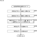
- the sensor 411 of the distance measuring device 401 generates an i signal and a q signal in step S401.
- the signal processing unit 412 processes the i signal and the q signal.
- step S403 the bit depth correction unit 413 corrects the bit depths of the i signal and the q signal based on the fed-back learning result.
- step S404 the coding unit 414 encodes the i signal and the q signal whose bit depth has been corrected, and generates coded data. The coding unit 414 transmits the generated coded data to the detection device 402.
- the decoding unit 421 of the detection device 402 receives the coded data in step S421.
- the decoding unit 421 decodes the coded data and generates the i signal and the q signal in the state before the bit depth is reverse-corrected.
- step S423 the detection unit 422 detects a desired subject or the like using the i signal and the q signal in the state before the bit depth is reverse-corrected based on the learning result fed back from the learning unit 423. , Output the detection data.
- step S424 the learning unit 424 learns about the detection and feeds back the learning result to the detection unit 422.
- step S425 the learning unit 424 transmits the learning result to the distance measuring device 401.
- the bit depth correction unit 413 of the distance measuring device 401 receives the learning result in step S406.
- the distance measuring device 401 and the detecting device 402 can suppress an increase in the processing load of the sensing data.
- FIG. 28 is a block diagram showing an example of a configuration of a distance measuring device, which is an aspect of an information processing device to which the present technology is applied.
- the distance measuring device 500 shown in FIG. 28 is a device that measures the distance to the subject by the indirect TOF method, like the distance measuring device 100.
- the ranging device 500 corrects the bit depth before and after signal processing.
- the distance measuring device 500 includes a sensor 101, an i signal generation unit 102, a sensing gamma correction unit 501, a signal processing unit 103, a sensing inverse gamma correction unit 502, a q signal generation unit 107, and a sensing gamma correction. It has a unit 503, a signal processing unit 108, a sensing inverse gamma correction unit 504, a phase difference detection unit 112, and a depth calculation unit 113.
- the sensing gamma correction unit 501 is the same processing unit as the sensing gamma correction unit 131, and performs the same processing.
- the sensing gamma correction unit 501 acquires the i signal supplied from the i signal generation unit 102, corrects the bit depth thereof, and supplies the corrected i signal to the signal processing unit 103.
- the signal processing unit 103 acquires the corrected i signal supplied from the sensing gamma correction unit 501 and performs signal processing.
- the signal processing unit 103 can perform signal processing on the i signal in a state where the bit depth is reduced. Therefore, it is possible to suppress an increase in the load of the signal processing unit 103.
- the i signal to be signal processed becomes non-linear. Therefore, the signal processing unit 103 may perform signal processing that is less affected by the linearity of the input data. For example, the signal processing unit 103 can perform processing such as noise reduction.
- the sensing inverse gamma correction unit 502 acquires the i signal for which signal processing has been appropriately performed by the signal processing unit 103, reverse-corrects the bit depth thereof, and returns it to a linear signal.
- the sensing inverse gamma correction unit 502 supplies the i signal returned to the original bit depth by the inverse correction to the phase difference detection unit 112.
- the sensing gamma correction unit 503 performs the same processing on the q signal as the sensing gamma correction unit 501. That is, the sensing gamma correction unit 501 corrects the bit depth of the q signal, which is the target of signal processing by the signal processing unit 108.
- the signal processing unit 108 can perform signal processing on the q signal in a state where the bit depth is reduced. Therefore, it is possible to suppress an increase in the load of the signal processing unit 108.
- the q signal to be signal processed becomes non-linear. Therefore, the signal processing unit 108 may perform signal processing that is less affected by the linearity of the input data. For example, the signal processing unit 108 can perform processing such as noise reduction.
- the sensing inverse gamma correction unit 504 performs the same processing as the sensing inverse gamma correction unit 502 for the q signal. That is, the sensing inverse gamma correction unit 504 acquires the q signal for which signal processing has been appropriately performed by the signal processing unit 108, reverse-corrects the bit depth thereof, and returns the signal to a linear signal. The sensing inverse gamma correction unit 504 supplies the q signal returned to the original bit depth by the inverse correction to the phase difference detection unit 112.
- the ranging device 500 can suppress an increase in calculation cost and mounting cost related to signal processing.
- each processing unit may be configured by a logic circuit that realizes the above-mentioned processing.
- each processing unit may have, for example, a CPU, ROM, RAM, etc., and execute a program using them to realize the above-mentioned processing.
- each processing unit may have both configurations, and a part of the above-mentioned processing may be realized by a logic circuit, and the other may be realized by executing a program.
- the configurations of the respective processing units may be independent of each other. For example, some processing units realize a part of the above-mentioned processing by a logic circuit, and some other processing units execute a program.
- the above-mentioned processing may be realized by the other processing unit by both the logic circuit and the execution of the program.
- each process of steps S501 to S503 is executed in the same manner as each process of steps S101 to S103 of FIG.
- step S504 the sensing gamma correction unit 501 gamma corrects the i signal. Further, in step S505, the sensing gamma correction unit 503 gamma-corrects the q signal.
- step S506 the signal processing unit 103 processes the i signal. Further, in step S507, the signal processing unit 108 processes the q signal.
- step S508 the sensing inverse gamma correction unit 502 inverse gamma corrects the i signal. Further, in step S509, the sensing inverse gamma correction unit 504 reverse gamma corrects the q signal.
- step S513 When the process of step S513 is completed, the distance measurement process is completed.
- the ranging device 500 can suppress an increase in calculation cost and mounting cost related to signal processing. That is, it is possible to suppress an increase in the processing load of sensing data.
- the series of processes described above can be executed by hardware or software.
- the programs constituting the software are installed on the computer.
- the computer includes a computer embedded in dedicated hardware, a general-purpose personal computer capable of executing various functions by installing various programs, and the like.
- FIG. 30 is a block diagram showing a configuration example of computer hardware that executes the above-mentioned series of processes programmatically.
- the CPU Central Processing Unit
- ROM Read Only Memory
- RAM Random Access Memory
- the input / output interface 910 is also connected to the bus 904.
- An input unit 911, an output unit 912, a storage unit 913, a communication unit 914, and a drive 915 are connected to the input / output interface 910.
- the input unit 911 includes, for example, a keyboard, a mouse, a microphone, a touch panel, an input terminal, and the like.
- the output unit 912 includes, for example, a display, a speaker, an output terminal, and the like.
- the storage unit 913 includes, for example, a hard disk, a RAM disk, a non-volatile memory, or the like.
- the communication unit 914 includes, for example, a network interface.
- the drive 915 drives a removable medium 921 such as a magnetic disk, an optical disk, a magneto-optical disk, or a semiconductor memory.
- the CPU 901 loads the program stored in the storage unit 913 into the RAM 903 via the input / output interface 910 and the bus 904 and executes the above-described series. Is processed.
- the RAM 903 also appropriately stores data and the like necessary for the CPU 901 to execute various processes.
- the program executed by the computer can be recorded and applied to the removable media 921 as a package media or the like, for example.
- the program can be installed in the storage unit 913 via the input / output interface 910 by mounting the removable media 921 in the drive 915.
- This program can also be provided via wired or wireless transmission media such as local area networks, the Internet, and digital satellite broadcasting. In that case, the program can be received by the communication unit 914 and installed in the storage unit 913.
- this program can be installed in advance in ROM 902 or storage unit 913.
- the technology according to the present disclosure can be applied to various products.
- the technology according to the present disclosure is realized as a device mounted on a moving body of any kind such as an automobile, an electric vehicle, a hybrid electric vehicle, a motorcycle, a bicycle, a personal mobility, an airplane, a drone, a ship, and a robot. You may.
- FIG. 31 is a block diagram showing a schematic configuration example of a vehicle control system, which is an example of a mobile control system to which the technology according to the present disclosure can be applied.
- the vehicle control system 12000 includes a plurality of electronic control units connected via the communication network 12001.
- the vehicle control system 12000 includes a drive system control unit 12010, a body system control unit 12020, an outside information detection unit 12030, an in-vehicle information detection unit 12040, and an integrated control unit 12050.
- a microcomputer 12051, an audio image output unit 12052, and an in-vehicle network I / F (interface) 12053 are shown as a functional configuration of the integrated control unit 12050.
- the drive system control unit 12010 controls the operation of the device related to the drive system of the vehicle according to various programs.
- the drive system control unit 12010 provides a driving force generator for generating the driving force of the vehicle such as an internal combustion engine or a driving motor, a driving force transmission mechanism for transmitting the driving force to the wheels, and a steering angle of the vehicle. It functions as a control device such as a steering mechanism for adjusting and a braking device for generating a braking force of a vehicle.
- the body system control unit 12020 controls the operation of various devices mounted on the vehicle body according to various programs.
- the body system control unit 12020 functions as a keyless entry system, a smart key system, a power window device, or a control device for various lamps such as headlamps, back lamps, brake lamps, blinkers or fog lamps.
- the body system control unit 12020 may be input with radio waves transmitted from a portable device that substitutes for the key or signals of various switches.
- the body system control unit 12020 receives inputs of these radio waves or signals and controls a vehicle door lock device, a power window device, a lamp, and the like.
- the vehicle outside information detection unit 12030 detects information outside the vehicle equipped with the vehicle control system 12000.
- the imaging unit 12031 is connected to the vehicle exterior information detection unit 12030.
- the vehicle outside information detection unit 12030 causes the image pickup unit 12031 to capture an image of the outside of the vehicle and receives the captured image.
- the vehicle exterior information detection unit 12030 may perform object detection processing or distance detection processing such as a person, a vehicle, an obstacle, a sign, or a character on the road surface based on the received image.
- the imaging unit 12031 is an optical sensor that receives light and outputs an electric signal according to the amount of the light received.
- the image pickup unit 12031 can output an electric signal as an image or can output it as distance measurement information. Further, the light received by the imaging unit 12031 may be visible light or invisible light such as infrared light.
- the in-vehicle information detection unit 12040 detects the in-vehicle information.
- a driver state detection unit 12041 that detects the driver's state is connected to the vehicle interior information detection unit 12040.
- the driver state detection unit 12041 includes, for example, a camera that images the driver, and the in-vehicle information detection unit 12040 determines the degree of fatigue or concentration of the driver based on the detection information input from the driver state detection unit 12041. It may be calculated, or it may be determined whether the driver is dozing.
- the microcomputer 12051 calculates the control target value of the driving force generator, the steering mechanism, or the braking device based on the information inside and outside the vehicle acquired by the vehicle exterior information detection unit 12030 or the vehicle interior information detection unit 12040, and the drive system control unit.
- a control command can be output to 12010.
- the microcomputer 12051 realizes ADAS (Advanced Driver Assistance System) functions including vehicle collision avoidance or impact mitigation, follow-up driving based on inter-vehicle distance, vehicle speed maintenance driving, vehicle collision warning, vehicle lane deviation warning, and the like. It is possible to perform cooperative control for the purpose of.
- ADAS Advanced Driver Assistance System
- the microcomputer 12051 controls the driving force generator, the steering mechanism, the braking device, and the like based on the information around the vehicle acquired by the vehicle exterior information detection unit 12030 or the vehicle interior information detection unit 12040. It is possible to perform coordinated control for the purpose of automatic driving, etc., which runs autonomously without depending on the operation.
- the microcomputer 12051 can output a control command to the body system control unit 12020 based on the information outside the vehicle acquired by the vehicle exterior information detection unit 12030.
- the microcomputer 12051 controls the headlamps according to the position of the preceding vehicle or the oncoming vehicle detected by the external information detection unit 12030, and performs coordinated control for the purpose of anti-glare such as switching the high beam to the low beam. It can be carried out.
- the audio image output unit 12052 transmits the output signal of at least one of the audio and the image to the output device capable of visually or audibly notifying the passenger or the outside of the vehicle of the information.
- an audio speaker 12061, a display unit 12062, and an instrument panel 12063 are exemplified as output devices.
- the display unit 12062 may include, for example, at least one of an onboard display and a heads-up display.
- FIG. 32 is a diagram showing an example of the installation position of the imaging unit 12031.
- the vehicle 12100 has imaging units 12101, 12102, 12103, 12104, 12105 as imaging units 12031.
- the imaging units 12101, 12102, 12103, 12104, 12105 are provided at positions such as the front nose, side mirrors, rear bumpers, back doors, and the upper part of the windshield in the vehicle interior of the vehicle 12100, for example.
- the image pickup unit 12101 provided on the front nose and the image pickup section 12105 provided on the upper part of the windshield in the vehicle interior mainly acquire an image in front of the vehicle 12100.
- the imaging units 12102 and 12103 provided in the side mirrors mainly acquire images of the side of the vehicle 12100.
- the imaging unit 12104 provided on the rear bumper or the back door mainly acquires an image of the rear of the vehicle 12100.
- the images in front acquired by the imaging units 12101 and 12105 are mainly used for detecting a preceding vehicle or a pedestrian, an obstacle, a traffic light, a traffic sign, a lane, or the like.
- FIG. 32 shows an example of the photographing range of the imaging units 12101 to 12104.
- the imaging range 12111 indicates the imaging range of the imaging unit 12101 provided on the front nose
- the imaging ranges 12112 and 12113 indicate the imaging ranges of the imaging units 12102 and 12103 provided on the side mirrors, respectively
- the imaging range 12114 indicates the imaging range of the imaging units 12102 and 12103.
- the imaging range of the imaging unit 12104 provided on the rear bumper or the back door is shown. For example, by superimposing the image data captured by the imaging units 12101 to 12104, a bird's-eye view image of the vehicle 12100 as viewed from above can be obtained.
- At least one of the imaging units 12101 to 12104 may have a function of acquiring distance information.
- at least one of the image pickup units 12101 to 12104 may be a stereo camera composed of a plurality of image pickup elements, or may be an image pickup device having pixels for phase difference detection.
- the microcomputer 12051 has a distance to each three-dimensional object within the imaging range 12111 to 12114 based on the distance information obtained from the imaging units 12101 to 12104, and a temporal change of this distance (relative velocity with respect to the vehicle 12100). By obtaining can. Further, the microcomputer 12051 can set an inter-vehicle distance to be secured in front of the preceding vehicle in advance, and can perform automatic braking control (including follow-up stop control), automatic acceleration control (including follow-up start control), and the like. In this way, it is possible to perform coordinated control for the purpose of automatic driving or the like in which the vehicle travels autonomously without depending on the operation of the driver.
- automatic braking control including follow-up stop control
- automatic acceleration control including follow-up start control
- the microcomputer 12051 converts three-dimensional object data related to a three-dimensional object into two-wheeled vehicles, ordinary vehicles, large vehicles, pedestrians, utility poles, and other three-dimensional objects based on the distance information obtained from the imaging units 12101 to 12104. It can be classified and extracted and used for automatic avoidance of obstacles. For example, the microcomputer 12051 distinguishes obstacles around the vehicle 12100 into obstacles that can be seen by the driver of the vehicle 12100 and obstacles that are difficult to see. Then, the microcomputer 12051 determines the collision risk indicating the risk of collision with each obstacle, and when the collision risk is equal to or higher than the set value and there is a possibility of collision, the microcomputer 12051 via the audio speaker 12061 or the display unit 12062. By outputting an alarm to the driver and performing forced deceleration and avoidance steering via the drive system control unit 12010, driving support for collision avoidance can be provided.
- At least one of the imaging units 12101 to 12104 may be an infrared camera that detects infrared rays.
- the microcomputer 12051 can recognize a pedestrian by determining whether or not a pedestrian is present in the captured image of the imaging units 12101 to 12104.
- pedestrian recognition includes, for example, a procedure for extracting feature points in an image captured by an imaging unit 12101 to 12104 as an infrared camera, and pattern matching processing for a series of feature points indicating the outline of an object to determine whether or not the pedestrian is a pedestrian. It is done by the procedure to determine.
- the audio image output unit 12052 When the microcomputer 12051 determines that a pedestrian is present in the captured images of the imaging units 12101 to 12104 and recognizes the pedestrian, the audio image output unit 12052 outputs a square contour line for emphasizing the recognized pedestrian.
- the display unit 12062 is controlled so as to superimpose and display. Further, the audio image output unit 12052 may control the display unit 12062 so as to display an icon or the like indicating a pedestrian at a desired position.
- the above is an example of a vehicle control system to which the technology according to the present disclosure can be applied.
- the technique according to the present disclosure can be applied to the vehicle exterior information detection unit 12030 and the vehicle interior information detection unit 12040 among the configurations described above.
- the driver's gesture it is possible to perform a process of recognizing the information, execute various operations (for example, an audio system, a navigation system, an air conditioning system) according to the gesture, and detect the driver's condition more accurately.
- the distance measurement by the distance measurement system 10 can be used to recognize the unevenness of the road surface and reflect it in the control of the suspension. Further, it is possible to suppress an increase in the processing load.
- this technology can be applied to a multi-viewpoint image coding / decoding system that encodes / decodes a multi-viewpoint image including images of a plurality of viewpoints (views).
- the present technology may be applied to the coding / decoding of each viewpoint (view).
- this technology is applied to a hierarchical image coding (scalable coding) / decoding system that encodes / decodes a hierarchical image that is layered (layered) so as to have a scalability function for a predetermined parameter. can do.
- the present technology may be applied in the coding / decoding of each layer.
- This technology can be applied to any configuration.
- this technology is a transmitter or receiver (for example, a television receiver or mobile phone) for satellite broadcasting, cable broadcasting such as cable TV, distribution on the Internet, and distribution to terminals by cellular communication, or It can be applied to various electronic devices such as devices (for example, hard disk recorders and cameras) that record images on media such as optical disks, magnetic disks, and flash memories, and reproduce images from these storage media.
- devices for example, hard disk recorders and cameras
- a processor as a system LSI (Large Scale Integration) or the like (for example, a video processor), a module using a plurality of processors (for example, a video module), a unit using a plurality of modules (for example, a video unit)
- a processor as a system LSI (Large Scale Integration) or the like
- a module using a plurality of processors for example, a video module
- a unit using a plurality of modules for example, a video unit
- it can be implemented as a configuration of a part of the device, such as a set (for example, a video set) in which other functions are added to the unit.
- this technology can be applied to a network system composed of a plurality of devices.
- the present technology may be implemented as cloud computing that is shared and jointly processed by a plurality of devices via a network.
- this technology is implemented in a cloud service that provides services related to images (moving images) to arbitrary terminals such as computers, AV (AudioVisual) devices, portable information processing terminals, and IoT (Internet of Things) devices. You may try to do it.
- the system means a set of a plurality of components (devices, modules (parts), etc.), and it does not matter whether all the components are in the same housing. Therefore, a plurality of devices housed in separate housings and connected via a network, and a device in which a plurality of modules are housed in one housing are both systems. ..
- Systems, devices, processing departments, etc. to which this technology is applied can be used in any field such as transportation, medical care, crime prevention, agriculture, livestock industry, mining, beauty, factories, home appliances, weather, nature monitoring, etc. .. Moreover, the use is arbitrary.
- this technology can be applied to systems and devices used for providing ornamental contents and the like.
- the present technology can be applied to systems and devices used for traffic such as traffic condition supervision and automatic driving control.
- the present technology can be applied to systems and devices used for security purposes.
- the present technology can be applied to a system or device used for automatic control of a machine or the like.
- the present technology can be applied to systems and devices used for agriculture and livestock industry.
- the present technology can also be applied to systems and devices for monitoring natural conditions such as volcanoes, forests and oceans, and wildlife. Further, for example, the present technology can be applied to systems and devices used for sports.
- the "flag” is information for identifying a plurality of states, and is not only information used for identifying two states of true (1) or false (0), but also three or more states. It also contains information that can identify the state. Therefore, the value that this "flag” can take may be, for example, 2 values of 1/0 or 3 or more values. That is, the number of bits constituting this "flag” is arbitrary, and may be 1 bit or a plurality of bits.
- the identification information (including the flag) is assumed to include not only the identification information in the bitstream but also the difference information of the identification information with respect to a certain reference information in the bitstream. In, the "flag” and “identification information” include not only the information but also the difference information with respect to the reference information.
- various information (metadata, etc.) related to the coded data may be transmitted or recorded in any form as long as it is associated with the coded data.
- the term "associate" means, for example, to make the other data available (linkable) when processing one data. That is, the data associated with each other may be combined as one data or may be individual data.
- the information associated with the coded data (image) may be transmitted on a transmission path different from the coded data (image).
- the information associated with the coded data (image) may be recorded on a recording medium (or another recording area of the same recording medium) different from the coded data (image). good.
- this "association" may be a part of the data, not the entire data. For example, an image and information corresponding to the image may be associated with each other in an arbitrary unit such as a plurality of frames, one frame, or a part within the frame.
- the embodiment of the present technology is not limited to the above-described embodiment, and various changes can be made without departing from the gist of the present technology.
- the configuration described as one device (or processing unit) may be divided and configured as a plurality of devices (or processing units).
- the configurations described above as a plurality of devices (or processing units) may be collectively configured as one device (or processing unit).
- a configuration other than the above may be added to the configuration of each device (or each processing unit).
- a part of the configuration of one device (or processing unit) may be included in the configuration of another device (or other processing unit). ..
- the above-mentioned program may be executed in any device.
- the device may have necessary functions (functional blocks, etc.) so that necessary information can be obtained.
- each step of one flowchart may be executed by one device, or may be shared and executed by a plurality of devices.
- the plurality of processes may be executed by one device, or may be shared and executed by a plurality of devices.
- a plurality of processes included in one step can be executed as processes of a plurality of steps.
- the processes described as a plurality of steps can be collectively executed as one step.
- the processing of the steps for writing the program may be executed in chronological order in the order described in the present specification, and the calls may be made in parallel or in parallel. It may be executed individually at the required timing such as when it is broken. That is, as long as there is no contradiction, the processing of each step may be executed in an order different from the above-mentioned order. Further, the processing of the step for writing this program may be executed in parallel with the processing of another program, or may be executed in combination with the processing of another program.
- a plurality of technologies related to this technology can be independently implemented independently as long as there is no contradiction.
- any plurality of the present technologies can be used in combination.
- some or all of the techniques described in any of the embodiments may be combined with some or all of the techniques described in other embodiments. It is also possible to carry out a part or all of any of the above-mentioned techniques in combination with other techniques not described above.
- the present technology can also have the following configurations.
- a bit depth correction unit that corrects the bit depth of intermediate data generated from sensing data obtained by an indirect TOF (Time-of-Flight) sensor, and a bit depth correction unit.
- An information processing device including a coding unit that encodes the intermediate data whose bit depth has been corrected and generates coded data.
- the bit depth correction unit corrects the bit depth of the intermediate data by using a gamma curve which is a predetermined curve showing input / output characteristics.
- the bit depth correction unit corrects the bit depth of the intermediate data by using a gamma curve designed based on the calculation accuracy required in the subsequent processing.
- the bit depth correction unit corrects the bit depth of the intermediate data by using a gamma curve derived by integrating the reciprocal of the minimum quantization value set to satisfy the calculation accuracy.
- the information processing device according to (3).
- the bit depth correction unit corrects the bit depth of the i signal of the intermediate data and the bit depth of the q signal independently of each other.
- the coding unit encodes the i signal and the q signal whose bit depth has been corrected independently of each other, and generates the coded data of the i signal and the coded data of the q signal, respectively.
- the information processing apparatus according to any one of 1) to (4).
- the bit depth correction unit corrects the bit depth of the intermediate data of the multidimensional vector data including both the i signal and the q signal.
- the information processing apparatus according to any one of (1) to (4), wherein the coding unit encodes the intermediate data of the multidimensional vector data whose bit depth has been corrected and generates the coded data. (7) A bit allocation amount determining unit for determining the bit amount to be allocated to each of the i signal and the q signal based on the total bit amount is further provided. The information processing apparatus according to (6), wherein the bit depth correction unit corrects the bit depths of the i signal and the q signal based on the determined bit amount. (8) Further provided with a base quantization amount calculation unit for calculating the base quantization amount of each of the i signal and the q signal.
- the bit allocation amount determining unit determines the bit amount to be allocated to each of the i signal and the q signal based on the total bit amount and the base quantization amount of each of the i signal and the q signal.
- the information processing apparatus according to (7).
- a permissible error amount calculation unit for calculating the permissible error amount of each of the i signal and the q signal is further provided.
- the base quantization amount calculation unit is The base quantization amount of the i signal is calculated based on the tolerance amount of the i signal.
- a block division unit for dividing each of the i signal and the q signal into block units is further provided.
- the bit depth correction unit corrects the bit depth of the intermediate data for each block.
- Any of (1) to (11) further comprising a signal processing unit that performs signal processing that does not require data linearity with respect to the intermediate data whose bit depth has been corrected by the bit depth correction unit. Information processing device described in Crab.
- the information processing apparatus according to any one of (1) to (12), further comprising a decoding unit that decodes the coded data and generates the intermediate data.
- the information processing apparatus according to (13), further including a reverse bit depth correction unit that reversely corrects the bit depth of the intermediate data generated by the decoding unit.
- An information processing method that encodes the intermediate data whose bit depth has been corrected and generates encoded data.
Landscapes
- Engineering & Computer Science (AREA)
- Multimedia (AREA)
- Signal Processing (AREA)
- Optical Radar Systems And Details Thereof (AREA)
- Measurement Of Optical Distance (AREA)
Priority Applications (2)
| Application Number | Priority Date | Filing Date | Title |
|---|---|---|---|
| US17/904,137 US12206867B2 (en) | 2020-02-21 | 2021-02-08 | Information processing device and method |
| JP2022501808A JP7615116B2 (ja) | 2020-02-21 | 2021-02-08 | 情報処理装置および方法 |
Applications Claiming Priority (2)
| Application Number | Priority Date | Filing Date | Title |
|---|---|---|---|
| JP2020-028089 | 2020-02-21 | ||
| JP2020028089 | 2020-02-21 |
Publications (1)
| Publication Number | Publication Date |
|---|---|
| WO2021166707A1 true WO2021166707A1 (ja) | 2021-08-26 |
Family
ID=77391128
Family Applications (1)
| Application Number | Title | Priority Date | Filing Date |
|---|---|---|---|
| PCT/JP2021/004515 Ceased WO2021166707A1 (ja) | 2020-02-21 | 2021-02-08 | 情報処理装置および方法 |
Country Status (3)
| Country | Link |
|---|---|
| US (1) | US12206867B2 (https=) |
| JP (1) | JP7615116B2 (https=) |
| WO (1) | WO2021166707A1 (https=) |
Citations (3)
| Publication number | Priority date | Publication date | Assignee | Title |
|---|---|---|---|---|
| WO2013028121A1 (en) * | 2011-08-25 | 2013-02-28 | Telefonaktiebolaget L M Ericsson (Publ) | Depth map encoding and decoding |
| US20140285626A1 (en) * | 2013-03-25 | 2014-09-25 | Microsoft Corporation | Representation and Compression of Depth Data |
| WO2019124248A1 (ja) * | 2017-12-21 | 2019-06-27 | 株式会社ソニー・インタラクティブエンタテインメント | 画像処理装置、コンテンツ処理装置、コンテンツ処理システム、および画像処理方法 |
Family Cites Families (3)
| Publication number | Priority date | Publication date | Assignee | Title |
|---|---|---|---|---|
| EP1769459B1 (en) * | 2004-05-31 | 2014-11-26 | Phase One A/S | Image compression for rapid high-quality imaging |
| KR101278238B1 (ko) * | 2006-10-16 | 2013-06-24 | 삼성전자주식회사 | 디지털 영상 처리 장치에서 영상 편집 방법 |
| WO2020174588A1 (ja) * | 2019-02-26 | 2020-09-03 | 株式会社ソシオネクスト | 情報処理装置および情報処理方法 |
-
2021
- 2021-02-08 WO PCT/JP2021/004515 patent/WO2021166707A1/ja not_active Ceased
- 2021-02-08 US US17/904,137 patent/US12206867B2/en active Active
- 2021-02-08 JP JP2022501808A patent/JP7615116B2/ja active Active
Patent Citations (3)
| Publication number | Priority date | Publication date | Assignee | Title |
|---|---|---|---|---|
| WO2013028121A1 (en) * | 2011-08-25 | 2013-02-28 | Telefonaktiebolaget L M Ericsson (Publ) | Depth map encoding and decoding |
| US20140285626A1 (en) * | 2013-03-25 | 2014-09-25 | Microsoft Corporation | Representation and Compression of Depth Data |
| WO2019124248A1 (ja) * | 2017-12-21 | 2019-06-27 | 株式会社ソニー・インタラクティブエンタテインメント | 画像処理装置、コンテンツ処理装置、コンテンツ処理システム、および画像処理方法 |
Non-Patent Citations (1)
| Title |
|---|
| SAM W. HUTCHINGS ET AL.: "A Reconfigurable 3-D-Stacked SPAD Imager With In- Pixel Histogramming for Flash LIDAR or High-Speed Time-of-Flight Imaging", IEEE JOURNAL OF SOLID-STATE CIRCUITS, vol. 54, no. 11, November 2019 (2019-11-01), pages 2947 - 2956, XP011751666, DOI: 10.1109/JSSC.2019.2939083 * |
Also Published As
| Publication number | Publication date |
|---|---|
| US12206867B2 (en) | 2025-01-21 |
| US20230066438A1 (en) | 2023-03-02 |
| JP7615116B2 (ja) | 2025-01-16 |
| JPWO2021166707A1 (https=) | 2021-08-26 |
Similar Documents
| Publication | Publication Date | Title |
|---|---|---|
| US12345806B2 (en) | Extrinsic parameter calibration for 4D millimeter-wave radar and camera based on adaptive projection error | |
| JP6683280B1 (ja) | センサ装置、信号処理方法 | |
| US11214268B2 (en) | Methods and apparatus for unsupervised multimodal anomaly detection for autonomous vehicles | |
| JP7127539B2 (ja) | 画像処理装置および画像処理方法 | |
| CN110268450B (zh) | 图像处理装置和图像处理方法 | |
| JP6939807B2 (ja) | 画像処理装置および画像処理方法 | |
| KR102790254B1 (ko) | 센서 장치 및 파라미터 설정 방법 | |
| US11188090B2 (en) | Autonomous driving control apparatus, vehicle having the same and method for controlling vehicle | |
| KR102790251B1 (ko) | 센서 장치 및 신호 처리 방법 | |
| CN110691986B (zh) | 用于计算机视觉的设备、方法和非暂时性计算机可读记录介质 | |
| EP3493165A1 (en) | Image processing device and image processing method | |
| JPWO2018021067A1 (ja) | 画像処理装置および画像処理方法 | |
| US11659154B1 (en) | Virtual horizontal stereo camera | |
| US10991144B2 (en) | Image processing apparatus and image processing method | |
| CN109844813A (zh) | 图像处理装置和图像处理方法 | |
| JPWO2018021068A1 (ja) | 画像処理装置および画像処理方法 | |
| WO2020116206A1 (ja) | 情報処理装置、および情報処理方法、並びにプログラム | |
| US10999498B2 (en) | Image processing apparatus and image processing method | |
| WO2020080139A1 (ja) | センサ装置、パラメータ設定方法 | |
| CN110412598A (zh) | 测距处理装置、测距模块、测距处理方法和程序 | |
| Grewe et al. | Towards a generic and efficient environment model for ADAS | |
| US11840253B1 (en) | Vision based, in-vehicle, remote command assist | |
| JP7517349B2 (ja) | 信号処理装置、信号処理方法、および、測距装置 | |
| WO2022004412A1 (ja) | 情報処理装置、情報処理方法、並びにプログラム | |
| KR102452536B1 (ko) | 주변차량 정보 전송 장치 및 방법 |
Legal Events
| Date | Code | Title | Description |
|---|---|---|---|
| 121 | Ep: the epo has been informed by wipo that ep was designated in this application |
Ref document number: 21757849 Country of ref document: EP Kind code of ref document: A1 |
|
| ENP | Entry into the national phase |
Ref document number: 2022501808 Country of ref document: JP Kind code of ref document: A |
|
| NENP | Non-entry into the national phase |
Ref country code: DE |
|
| 122 | Ep: pct application non-entry in european phase |
Ref document number: 21757849 Country of ref document: EP Kind code of ref document: A1 |