WO2021161925A1 - Relay control method and communication node - Google Patents
Relay control method and communication node Download PDFInfo
- Publication number
- WO2021161925A1 WO2021161925A1 PCT/JP2021/004381 JP2021004381W WO2021161925A1 WO 2021161925 A1 WO2021161925 A1 WO 2021161925A1 JP 2021004381 W JP2021004381 W JP 2021004381W WO 2021161925 A1 WO2021161925 A1 WO 2021161925A1
- Authority
- WO
- WIPO (PCT)
- Prior art keywords
- node
- relay
- data
- base station
- control method
- Prior art date
Links
- 238000000034 method Methods 0.000 title claims abstract description 49
- 238000004891 communication Methods 0.000 title claims description 58
- 230000005540 biological transmission Effects 0.000 claims abstract description 62
- 238000010295 mobile communication Methods 0.000 claims abstract description 43
- 230000004044 response Effects 0.000 claims description 9
- 239000000872 buffer Substances 0.000 claims description 3
- 238000010586 diagram Methods 0.000 description 12
- 238000012545 processing Methods 0.000 description 10
- 230000006870 function Effects 0.000 description 6
- 238000013468 resource allocation Methods 0.000 description 4
- 235000008694 Humulus lupulus Nutrition 0.000 description 3
- 238000013507 mapping Methods 0.000 description 3
- 230000011664 signaling Effects 0.000 description 3
- 230000003111 delayed effect Effects 0.000 description 2
- 230000006866 deterioration Effects 0.000 description 2
- 238000005516 engineering process Methods 0.000 description 2
- 230000000737 periodic effect Effects 0.000 description 2
- 230000001052 transient effect Effects 0.000 description 2
- 230000006978 adaptation Effects 0.000 description 1
- 230000002776 aggregation Effects 0.000 description 1
- 238000004220 aggregation Methods 0.000 description 1
- 230000006835 compression Effects 0.000 description 1
- 238000007906 compression Methods 0.000 description 1
- 230000006837 decompression Effects 0.000 description 1
- 230000007774 longterm Effects 0.000 description 1
- 238000007726 management method Methods 0.000 description 1
- 238000012546 transfer Methods 0.000 description 1
- 238000011144 upstream manufacturing Methods 0.000 description 1
- 239000002699 waste material Substances 0.000 description 1
Images


Classifications
-
- H—ELECTRICITY
- H04—ELECTRIC COMMUNICATION TECHNIQUE
- H04B—TRANSMISSION
- H04B7/00—Radio transmission systems, i.e. using radiation field
- H04B7/14—Relay systems
- H04B7/15—Active relay systems
- H04B7/155—Ground-based stations
- H04B7/15528—Control of operation parameters of a relay station to exploit the physical medium
-
- H—ELECTRICITY
- H04—ELECTRIC COMMUNICATION TECHNIQUE
- H04W—WIRELESS COMMUNICATION NETWORKS
- H04W72/00—Local resource management
- H04W72/50—Allocation or scheduling criteria for wireless resources
- H04W72/54—Allocation or scheduling criteria for wireless resources based on quality criteria
-
- H—ELECTRICITY
- H04—ELECTRIC COMMUNICATION TECHNIQUE
- H04W—WIRELESS COMMUNICATION NETWORKS
- H04W28/00—Network traffic management; Network resource management
- H04W28/02—Traffic management, e.g. flow control or congestion control
- H04W28/0278—Traffic management, e.g. flow control or congestion control using buffer status reports
-
- H—ELECTRICITY
- H04—ELECTRIC COMMUNICATION TECHNIQUE
- H04W—WIRELESS COMMUNICATION NETWORKS
- H04W36/00—Hand-off or reselection arrangements
- H04W36/0005—Control or signalling for completing the hand-off
- H04W36/0055—Transmission or use of information for re-establishing the radio link
-
- H—ELECTRICITY
- H04—ELECTRIC COMMUNICATION TECHNIQUE
- H04W—WIRELESS COMMUNICATION NETWORKS
- H04W84/00—Network topologies
- H04W84/02—Hierarchically pre-organised networks, e.g. paging networks, cellular networks, WLAN [Wireless Local Area Network] or WLL [Wireless Local Loop]
- H04W84/04—Large scale networks; Deep hierarchical networks
- H04W84/042—Public Land Mobile systems, e.g. cellular systems
- H04W84/047—Public Land Mobile systems, e.g. cellular systems using dedicated repeater stations
-
- H—ELECTRICITY
- H04—ELECTRIC COMMUNICATION TECHNIQUE
- H04W—WIRELESS COMMUNICATION NETWORKS
- H04W88/00—Devices specially adapted for wireless communication networks, e.g. terminals, base stations or access point devices
- H04W88/08—Access point devices
- H04W88/085—Access point devices with remote components
Abstract
A relay control method according to a first aspect is a method used in a mobile communication system in which one or a plurality of relay nodes relay data from user equipment to a base station. The relay control method comprises: a first lower node predicting an expected transmission data amount, which is an amount of data expected to be transmitted from the first lower node to a first upper node above the first lower node in a subsequent certain period; and the first lower node transmitting data amount information indicating the expected transmission data amount to the first upper node.
Description
本開示は、移動通信システムにおいて用いる中継制御方法及び通信ノードに関する。
The present disclosure relates to a relay control method and a communication node used in a mobile communication system.
移動通信システムの標準化プロジェクトである3GPP(3rd Generation Partnership Project)において、IAB(Integrated Access and Backhaul)ノードと呼ばれる新たな中継ノードが検討されている。1つ又は複数の中継ノードが基地局とユーザ装置との間の通信に介在し、この通信に対する中継を行う。
In 3GPP (3rd Generation Partnership Project), which is a standardization project for mobile communication systems, a new relay node called an IAB (Integrated Access and Backhaul) node is being considered. One or more relay nodes intervene in the communication between the base station and the user device, and relay the communication.
また、3GPPにおいて、ユーザ装置を中継ノードとして用いるサイドリンク中継の技術が検討されている。サイドリンク中継は、中継ユーザ装置(Relay UE)と呼ばれる中継ノードが、基地局と遠隔ユーザ装置(Remote UE)との間の通信に介在し、この通信に対する中継を行う技術である。
Also, in 3GPP, a side link relay technology that uses a user device as a relay node is being studied. Side link relay is a technology in which a relay node called a relay user device (Relay UE) intervenes in communication between a base station and a remote user device (Remote UE) and relays to this communication.
第1の態様に係る中継制御方法は、1つ又は複数の中継ノードがユーザ装置から基地局へのデータを中継する移動通信システムにおいて用いる方法である。前記中継制御方法は、第1下位ノードが、前記第1下位ノードから前記第1下位ノードよりも上位の第1上位ノードに対して以後の一定期間内に送信する見込みのデータ量である送信見込みデータ量を予測することと、前記第1下位ノードが、前記送信見込みデータ量を示すデータ量情報を前記第1上位ノードに送信することとを有する。前記第1下位ノードは、前記1つ又は複数の中継ノードに含まれる中継ノード、又は前記ユーザ装置である。前記第1上位ノードは、前記1つ又は複数の中継ノードに含まれる中継ノード、又は前記基地局である。
The relay control method according to the first aspect is a method used in a mobile communication system in which one or more relay nodes relay data from a user device to a base station. In the relay control method, the transmission probability is the amount of data that the first lower node is expected to transmit from the first lower node to the first upper node higher than the first lower node within a certain period thereafter. The first lower node predicts the amount of data, and the first lower node transmits data amount information indicating the expected transmission amount of data to the first upper node. The first lower node is a relay node included in the one or more relay nodes, or the user device. The first higher-level node is a relay node included in the one or more relay nodes, or the base station.
第2の態様に係る通信ノードは、1つ又は複数の中継ノードがユーザ装置から基地局へのデータを中継する移動通信システムにおいて、第1下位ノードとして動作する装置である。前記通信ノードは、前記第1下位ノードから前記第1下位ノードよりも上位の第1上位ノードに対して以後の一定期間内に送信する見込みのデータ量である送信見込みデータ量を予測する制御部と、前記送信見込みデータ量を示すデータ量情報を前記第1上位ノードに送信する送信部とを有する。前記第1下位ノードは、前記1つ又は複数の中継ノードに含まれる中継ノード、又は前記ユーザ装置である。前記第1上位ノードは、前記1つ又は複数の中継ノードに含まれる中継ノード、又は前記基地局である。
The communication node according to the second aspect is a device that operates as a first lower node in a mobile communication system in which one or more relay nodes relay data from a user device to a base station. The communication node is a control unit that predicts the amount of expected transmission data, which is the amount of data expected to be transmitted from the first lower node to the first upper node higher than the first lower node within a certain period thereafter. And a transmission unit that transmits data amount information indicating the transmission expected data amount to the first higher-level node. The first lower node is a relay node included in the one or more relay nodes, or the user device. The first higher-level node is a relay node included in the one or more relay nodes, or the base station.
第3の態様に係る中継制御方法は、1つ又は複数の中継ノードがユーザ装置から第1基地局へのデータを中継する移動通信システムにおいて用いる方法である。前記中継制御方法は、前記1つ又は複数の中継ノードに含まれる第1中継ノードが、前記第1中継ノードよりも下位の下位ノードからデータを受信することと、前記第1中継ノードが、前記下位ノードから受信したデータを、前記第1中継ノードよりも上位の上位ノードへの当該受信したデータの送信が完了するまで保持することと、前記第1中継ノードが、前記第1基地局とは異なる第2基地局又は前記第2基地局の配下の第2中継ノードへのハンドオーバを実行することと、前記第1中継ノードが、前記ハンドオーバの実行に応じて、前記保持しているデータを破棄することとを有する。
The relay control method according to the third aspect is a method used in a mobile communication system in which one or more relay nodes relay data from a user device to a first base station. In the relay control method, the first relay node included in the one or more relay nodes receives data from a lower node lower than the first relay node, and the first relay node is said to have the same. The data received from the lower node is held until the transmission of the received data to the upper node higher than the first relay node is completed, and the first relay node is the first base station. Executing a handover to a different second base station or a second relay node under the control of the second base station, and the first relay node discarding the held data in response to the execution of the handover. Have to do.
第4の態様に係る通信ノードは、1つ又は複数の中継ノードがユーザ装置から第1基地局へのデータを中継する移動通信システムにおいて、前記1つ又は複数の中継ノードに含まれる第1中継ノードとして動作する装置である。前記通信ノードは、前記第1中継ノードよりも下位の下位ノードからデータを受信する受信部と、前記下位ノードから受信したデータを、前記第1中継ノードよりも上位の上位ノードへの当該受信したデータの送信が完了するまで保持する制御部とを有する。前記制御部は、前記第1基地局とは異なる第2基地局又は前記第2基地局の配下の第2中継ノードへのハンドオーバを前記第1中継ノードが実行することに応じて、前記保持しているデータを破棄する。
The communication node according to the fourth aspect is a first relay included in the one or more relay nodes in a mobile communication system in which one or more relay nodes relay data from a user device to a first base station. A device that operates as a node. The communication node receives data received from a lower node lower than the first relay node and data received from the lower node to a higher node higher than the first relay node. It has a control unit that holds the data until the transmission of data is completed. The control unit holds the second base station different from the first base station or the second relay node under the control of the second base station in response to the first relay node performing the handover. Discard the data.
1つ又は複数の中継ノードがユーザ装置と基地局との間の通信を中継する場合において、ユーザ装置から基地局へのデータの中継を適切に制御する中継制御方法の実現が望まれる。
When one or more relay nodes relay the communication between the user device and the base station, it is desired to realize a relay control method that appropriately controls the relay of data from the user device to the base station.
そこで、本開示は、上りリンクのデータ中継を適切に制御することを目的とする。
Therefore, the purpose of this disclosure is to appropriately control uplink data relay.
図面を参照しながら、一実施形態に係る移動通信システムについて説明する。図面の記載において、同一又は類似の部分には同一又は類似の符号を付している。
The mobile communication system according to the embodiment will be described with reference to the drawings. In the description of the drawings, the same or similar parts are designated by the same or similar reference numerals.
[第1実施形態]
(移動通信システムの第1構成例)
まず、第1実施形態に係る移動通信システムの第1構成例について説明する。図1は、第1実施形態に係る移動通信システム1の第1構成例を示す図である。 [First Embodiment]
(First configuration example of mobile communication system)
First, a first configuration example of the mobile communication system according to the first embodiment will be described. FIG. 1 is a diagram showing a first configuration example of themobile communication system 1 according to the first embodiment.
(移動通信システムの第1構成例)
まず、第1実施形態に係る移動通信システムの第1構成例について説明する。図1は、第1実施形態に係る移動通信システム1の第1構成例を示す図である。 [First Embodiment]
(First configuration example of mobile communication system)
First, a first configuration example of the mobile communication system according to the first embodiment will be described. FIG. 1 is a diagram showing a first configuration example of the
移動通信システム1は、3GPP規格に基づく第5世代(5G)移動通信システムである。具体的には、移動通信システム1における無線アクセス方式は、5Gの無線アクセス方式であるNR(New Radio)である。但し、移動通信システム1には、LTE(Long Term Evolution)が少なくとも部分的に適用されてもよい。
Mobile communication system 1 is a 5th generation (5G) mobile communication system based on the 3GPP standard. Specifically, the wireless access system in the mobile communication system 1 is NR (New Radio), which is a 5G wireless access system. However, LTE (Long Term Evolution) may be applied to the mobile communication system 1 at least partially.
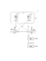
図1に示すように、移動通信システム1は、5Gコアネットワーク(5GC)10と、ユーザ装置(UE:User Equipment)100と、基地局(gNBと呼ばれる)200と、IABノード300とを有する。IABノード300は、中継ノードの第1の例である。第1実施形態において、基地局がNR基地局である一例について主として説明するが、基地局がLTE基地局(すなわち、eNB)であってもよい。
As shown in FIG. 1, the mobile communication system 1 has a 5G core network (5GC) 10, a user device (UE: User Equipment) 100, a base station (called gNB) 200, and an IAB node 300. The IAB node 300 is a first example of a relay node. In the first embodiment, an example in which the base station is an NR base station will be mainly described, but the base station may be an LTE base station (that is, eNB).
5GC10は、AMF(Access and Mobility Management Function)11及びUPF(User Plane Function)12を有する。AMF11は、UE100に対する各種モビリティ制御等を行う装置である。AMF11は、NAS(Non-Access Stratum)シグナリングを用いてUE100と通信することにより、UE100が在圏するエリアの情報を管理する。UPF12は、ユーザデータの転送制御等を行う装置である。
The 5GC10 has an AMF (Access and Mobility Management Function) 11 and an UPF (User Plane Function) 12. The AMF 11 is a device that performs various mobility controls and the like for the UE 100. The AMF 11 manages information on the area in which the UE 100 is located by communicating with the UE 100 using NAS (Non-Access Stratum) signaling. The UPF 12 is a device that controls the transfer of user data and the like.
各gNB200は、固定の無線通信装置であって、1又は複数のセルを管理する。セルは、無線通信エリアの最小単位を示す用語として用いられる。セルは、UE100との無線通信を行う機能又はリソースを示す用語として用いられることがある。1つのセルは1つのキャリア周波数に属する。
Each gNB 200 is a fixed wireless communication device and manages one or a plurality of cells. Cell is used as a term to indicate the smallest unit of wireless communication area. The cell may be used as a term for a function or resource for wireless communication with the UE 100. One cell belongs to one carrier frequency.
各gNB200は、NGインターフェイスと呼ばれるインターフェイスを介して5GC10と相互に接続される。図1において、5GC10に接続された2つのgNB200-1及びgNB200-2を例示している。
Each gNB200 is interconnected with the 5GC10 via an interface called an NG interface. FIG. 1 illustrates two gNB200-1 and gNB200-2 connected to 5GC10.
各gNB200は、Xnインターフェイスと呼ばれる基地局間インターフェイスを介して、隣接関係にある他のgNB200と相互に接続される。図1において、gNB200-1がgNB200-2と接続される一例を示している。
Each gNB 200 is interconnected with other gNB 200s in an adjacent relationship via an inter-base station interface called an Xn interface. FIG. 1 shows an example in which gNB200-1 is connected to gNB200-2.
各gNB200は、集約ユニット(CU:Central Unit)と分散ユニット(DU:Distributed Unit)とに分割されていてもよい。CU及びDUは、F1インターフェイスと呼ばれるインターフェイスを介して相互に接続される。F1プロトコルは、CUとDUとの間の通信プロトコルである。F1プロトコルには、制御プレーンのプロトコルであるF1-CプロトコルとユーザプレーンのプロトコルであるF1-Uプロトコルとがある。
Each gNB 200 may be divided into an aggregation unit (CU: Central Unit) and a distribution unit (DU: Distributed Unit). The CU and DU are connected to each other via an interface called the F1 interface. The F1 protocol is a communication protocol between CU and DU. The F1 protocol includes a control plane protocol, the F1-C protocol, and a user plane protocol, the F1-U protocol.
移動通信システム1は、バックホールにNRを用いて、NRアクセスの無線中継を可能とするIABをサポートする。ドナーgNB200-1は、ネットワーク側のNRバックホールの終端ノードであり、IABをサポートする追加機能を備えたgNB200である。バックホールは、複数のホップ(すなわち、複数のIABノード300)を介するマルチホップが可能である。
The mobile communication system 1 uses NR for the backhaul and supports IAB that enables wireless relay of NR access. The donor gNB200-1 is a terminal node of the NR backhaul on the network side, and is a gNB200 having an additional function of supporting IAB. The backhaul can be multi-hop through multiple hops (ie, multiple IAB nodes 300).
各IABノード300は、ユーザ装置機能部に相当するMT(Mobile Termination)と、基地局機能部に相当するDUとを有する。
Each IAB node 300 has an MT (Mobile Termination) corresponding to a user device function unit and a DU corresponding to a base station function unit.
MTは、上位ノード(上位のIABノード又はドナーgNB200-1)のDUに接続する。MTは、RRCを用いてドナーgNB200-1のCUに接続し、RRCメッセージ及びNASメッセージを運ぶシグナリング無線ベアラ(SRB)をドナーgNB200-1と確立する。MTのNR Uu無線インターフェイス上の隣接ノード(すなわち、上位ノード)は、「親ノード」と呼ばれることがある。IABノード300のMTと上位ノードとの間の無線リンクは、バックホールリンクと呼ばれる。
MT connects to the DU of the upper node (upper IAB node or donor gNB200-1). MT uses RRC to connect to the CU of donor gNB200-1 and establish a signaling radio bearer (SRB) carrying RRC and NAS messages with donor gNB200-1. Neighboring nodes (ie, higher-level nodes) on the MT's NR Uu radio interface are sometimes referred to as "parent nodes." The radio link between the MT of the IAB node 300 and the host node is called a backhaul link.
DUは、gNB200と同様に、セルを管理する。DUは、UE100及び下位のIABノードへのNR Uu無線インターフェイスを終端する。DUは、ドナーgNB200-1のCUへのF1プロトコルをサポートする。DUのNRアクセスインターフェイス上の隣接ノード(すなわち、下位ノード)は、「子ノード」と呼ばれることがある。
DU manages cells in the same way as gNB200. The DU terminates the NR Uu radio interface to the UE 100 and lower IAB nodes. The DU supports the F1 protocol to the CU of donor gNB200-1. Neighboring nodes (ie, subordinate nodes) on the DU's NR access interface are sometimes referred to as "child nodes."
1つ又は複数のホップを介してドナーgNB200-1に接続されるすべてのIABノード300は、ドナーgNB200-1をルートに持つDAG(Directed Acyclic Graph)トポロジを形成する。このDAGトポロジは、IABトポロジと呼ばれることもある。このDAGトポロジにおいて、親ノードの方向をアップストリーム又は上位と呼び、子ノードの方向をダウンストリーム又は下位と呼ぶことがある。
All IAB nodes 300 connected to the donor gNB200-1 via one or more hops form a DAG (Directed Acyclic Graph) topology with the donor gNB200-1 as the root. This DAG topology is sometimes referred to as the IAB topology. In this DAG topology, the direction of the parent node may be referred to as upstream or high, and the direction of the child node may be referred to as downstream or low.
図1において、IABノード300-1がドナーgNB200-1と無線で接続し、IABノード300-2がIABノード300-1と無線で接続し、F1プロトコルが2つのバックホールホップで伝送される一例を示している。
In FIG. 1, an example in which the IAB node 300-1 wirelessly connects to the donor gNB200-1, the IAB node 300-2 wirelessly connects to the IAB node 300-1, and the F1 protocol is transmitted in two backhaul hops. Is shown.
UE100は、セルとの無線通信を行う移動可能な無線通信装置である。UE100は、gNB200又はIABノード300との無線通信を行う装置であればよい。例えば、UE100は、携帯電話端末、タブレット端末、ノートPC、センサ若しくはセンサに設けられる装置、及び/又は車両若しくは車両に設けられる装置である。UE100は、アクセスリンクを介して上位ノード(IABノード300又はgNB200)と無線で接続される。
The UE 100 is a mobile wireless communication device that performs wireless communication with a cell. The UE 100 may be a device that performs wireless communication with the gNB 200 or the IAB node 300. For example, the UE 100 is a mobile phone terminal, a tablet terminal, a notebook PC, a sensor or a device provided in the sensor, and / or a vehicle or a device provided in the vehicle. The UE 100 is wirelessly connected to a higher-level node (IAB node 300 or gNB 200) via an access link.
図1において、UE100がIABノード300-2と無線で接続される一例を示している。UE100は、IABノード300-2及びIABノード300-1を介してドナーgNB200-1と間接的に通信する。具体的には、IABノード300-2及びIABノード300-1は、UE100からの上りリンクデータをドナーgNB200-1に中継し、gNB200-1からの下りリンクデータをUE100に中継する。
FIG. 1 shows an example in which the UE 100 is wirelessly connected to the IAB node 300-2. The UE 100 indirectly communicates with the donor gNB200-1 via the IAB node 300-2 and the IAB node 300-1. Specifically, the IAB node 300-2 and the IAB node 300-1 relay the uplink data from the UE 100 to the donor gNB200-1, and the downlink data from the gNB200-1 to the UE100.
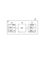
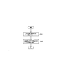
次に、第1実施形態に係る基地局であるgNB200の構成について説明する。図2は、gNB200の構成を示す図である。図2に示すように、gNB200は、無線通信部210と、ネットワーク通信部220と、制御部230とを有する。
Next, the configuration of the gNB 200, which is the base station according to the first embodiment, will be described. FIG. 2 is a diagram showing the configuration of gNB 200. As shown in FIG. 2, the gNB 200 has a wireless communication unit 210, a network communication unit 220, and a control unit 230.
無線通信部210は、UE100との無線通信及びIABノード300との無線通信を行う。無線通信部210は、受信部211及び送信部212を有する。受信部211は、制御部230の制御下で各種の受信を行う。受信部211はアンテナを含み、アンテナが受信する無線信号をベースバンド信号(受信信号)に変換して制御部230に出力する。送信部212は、制御部230の制御下で各種の送信を行う。送信部212はアンテナを含み、制御部230が出力するベースバンド信号(送信信号)を無線信号に変換してアンテナから送信する。
The wireless communication unit 210 performs wireless communication with the UE 100 and wireless communication with the IAB node 300. The wireless communication unit 210 has a receiving unit 211 and a transmitting unit 212. The receiving unit 211 performs various types of reception under the control of the control unit 230. The receiving unit 211 includes an antenna, converts the radio signal received by the antenna into a baseband signal (received signal), and outputs the radio signal to the control unit 230. The transmission unit 212 performs various transmissions under the control of the control unit 230. The transmission unit 212 includes an antenna, converts a baseband signal (transmission signal) output by the control unit 230 into a radio signal, and transmits the baseband signal (transmission signal) from the antenna.
ネットワーク通信部220は、5GC10との有線通信(又は無線通信)及び隣接する他のgNB200との有線通信(又は無線通信)を行う。ネットワーク通信部220は、受信部221及び送信部222を有する。受信部221は、制御部230の制御下で各種の受信を行う。受信部221は、外部から信号を受信して受信信号を制御部230に出力する。送信部222は、制御部230の制御下で各種の送信を行う。送信部222は、制御部230が出力する送信信号を外部に送信する。
The network communication unit 220 performs wired communication (or wireless communication) with the 5GC10 and wired communication (or wireless communication) with another adjacent gNB 200. The network communication unit 220 has a reception unit 221 and a transmission unit 222. The receiving unit 221 performs various types of reception under the control of the control unit 230. The receiving unit 221 receives a signal from the outside and outputs the received signal to the control unit 230. The transmission unit 222 performs various transmissions under the control of the control unit 230. The transmission unit 222 transmits the transmission signal output by the control unit 230 to the outside.
制御部230は、gNB200における各種の制御を行う。制御部230は、少なくとも1つのメモリと、メモリと電気的に接続された少なくとも1つのプロセッサとを含む。メモリは、プロセッサにより実行されるプログラム、及びプロセッサによる処理に用いられる情報を記憶する。プロセッサは、ベースバンドプロセッサとCPU(Central Processing Unit)とを含んでもよい。ベースバンドプロセッサは、ベースバンド信号の変調・復調及び符号化・復号等を行う。CPUは、メモリに記憶されるプログラムを実行して各種の処理を行う。プロセッサは、後述する各レイヤの処理を行う。
The control unit 230 performs various controls on the gNB 200. The control unit 230 includes at least one memory and at least one processor electrically connected to the memory. The memory stores a program executed by the processor and information used for processing by the processor. The processor may include a baseband processor and a CPU (Central Processing Unit). The baseband processor modulates / demodulates and encodes / decodes the baseband signal. The CPU executes a program stored in the memory to perform various processes. The processor performs processing of each layer described later.
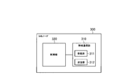
次に、第1実施形態に係る中継ノードの第1の例であるIABノード300の構成について説明する。図3は、IABノード300の構成を示す図である。図3に示すように、IABノード300は、無線通信部310と、制御部320とを有する。IABノード300は、無線通信部310を複数有していてもよい。
Next, the configuration of the IAB node 300, which is the first example of the relay node according to the first embodiment, will be described. FIG. 3 is a diagram showing the configuration of the IAB node 300. As shown in FIG. 3, the IAB node 300 has a wireless communication unit 310 and a control unit 320. The IAB node 300 may have a plurality of wireless communication units 310.
無線通信部310は、gNB200との無線通信(バックホールリンク)及びUE100との無線通信(アクセスリンク)を行う。バックホールリンク通信用の無線通信部310とアクセスリンク通信用の無線通信部310とが別々に設けられていてもよい。
The wireless communication unit 310 performs wireless communication with the gNB 200 (backhaul link) and wireless communication with the UE 100 (access link). The wireless communication unit 310 for backhaul link communication and the wireless communication unit 310 for access link communication may be provided separately.
無線通信部310は、受信部311及び送信部312を有する。受信部311は、制御部320の制御下で各種の受信を行う。受信部311はアンテナを含み、アンテナが受信する無線信号をベースバンド信号(受信信号)に変換して制御部320に出力する。送信部312は、制御部320の制御下で各種の送信を行う。送信部312はアンテナを含み、制御部320が出力するベースバンド信号(送信信号)を無線信号に変換してアンテナから送信する。
The wireless communication unit 310 has a receiving unit 311 and a transmitting unit 312. The receiving unit 311 performs various types of reception under the control of the control unit 320. The receiving unit 311 includes an antenna, converts the radio signal received by the antenna into a baseband signal (received signal), and outputs the radio signal to the control unit 320. The transmission unit 312 performs various transmissions under the control of the control unit 320. The transmission unit 312 includes an antenna, converts the baseband signal (transmission signal) output by the control unit 320 into a radio signal, and transmits the baseband signal (transmission signal) from the antenna.
制御部320は、IABノード300における各種の制御を行う。制御部320は、少なくとも1つのメモリと、メモリと電気的に接続された少なくとも1つのプロセッサとを含む。メモリは、プロセッサにより実行されるプログラム、及びプロセッサによる処理に用いられる情報を記憶する。プロセッサは、ベースバンドプロセッサ及びCPUを含んでもよい。ベースバンドプロセッサは、ベースバンド信号の変調・復調及び符号化・復号等を行う。CPUは、メモリに記憶されるプログラムを実行して各種の処理を行う。プロセッサは、後述する各レイヤの処理を行う。
The control unit 320 performs various controls on the IAB node 300. The control unit 320 includes at least one memory and at least one processor electrically connected to the memory. The memory stores a program executed by the processor and information used for processing by the processor. The processor may include a baseband processor and a CPU. The baseband processor modulates / demodulates and encodes / decodes the baseband signal. The CPU executes a program stored in the memory to perform various processes. The processor performs processing of each layer described later.
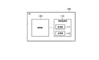
次に、第1実施形態に係るユーザ装置であるUE100の構成について説明する。図4は、UE100の構成を示す図である。図4に示すように、UE100は、無線通信部110と、制御部120とを有する。
Next, the configuration of the UE 100, which is the user device according to the first embodiment, will be described. FIG. 4 is a diagram showing the configuration of the UE 100. As shown in FIG. 4, the UE 100 has a wireless communication unit 110 and a control unit 120.
無線通信部110は、アクセスリンクにおける無線通信、すなわち、gNB200との無線通信及びIABノード300との無線通信を行う。また、無線通信部110は、サイドリンクにおける無線通信、すなわち、他のUE100との無線通信を行ってもよい。無線通信部110は、受信部111及び送信部112を有する。受信部111は、制御部120の制御下で各種の受信を行う。受信部111はアンテナを含み、アンテナが受信する無線信号をベースバンド信号(受信信号)に変換して制御部120に出力する。送信部112は、制御部120の制御下で各種の送信を行う。送信部112はアンテナを含み、制御部120が出力するベースバンド信号(送信信号)を無線信号に変換してアンテナから送信する。
The wireless communication unit 110 performs wireless communication on the access link, that is, wireless communication with the gNB 200 and wireless communication with the IAB node 300. Further, the wireless communication unit 110 may perform wireless communication on the side link, that is, wireless communication with another UE 100. The wireless communication unit 110 has a receiving unit 111 and a transmitting unit 112. The receiving unit 111 performs various types of reception under the control of the control unit 120. The receiving unit 111 includes an antenna, converts the radio signal received by the antenna into a baseband signal (received signal), and outputs the radio signal to the control unit 120. The transmission unit 112 performs various transmissions under the control of the control unit 120. The transmission unit 112 includes an antenna, converts a baseband signal (transmission signal) output by the control unit 120 into a radio signal, and transmits the baseband signal (transmission signal) from the antenna.
制御部120は、UE100における各種の制御を行う。制御部120は、少なくとも1つのメモリと、メモリと電気的に接続された少なくとも1つのプロセッサとを含む。メモリは、プロセッサにより実行されるプログラム、及びプロセッサによる処理に用いられる情報を記憶する。プロセッサは、ベースバンドプロセッサ及びCPUを含んでもよい。ベースバンドプロセッサは、ベースバンド信号の変調・復調及び符号化・復号等を行う。CPUは、メモリに記憶されるプログラムを実行して各種の処理を行う。プロセッサは、後述する各レイヤの処理を行う。
The control unit 120 performs various controls on the UE 100. The control unit 120 includes at least one memory and at least one processor electrically connected to the memory. The memory stores a program executed by the processor and information used for processing by the processor. The processor may include a baseband processor and a CPU. The baseband processor modulates / demodulates and encodes / decodes the baseband signal. The CPU executes a program stored in the memory to perform various processes. The processor performs processing of each layer described later.
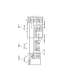
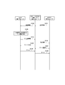
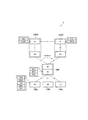
次に、第1実施形態に係る移動通信システム1の第1構成例におけるプロトコルスタック例について説明する。図5及び図6は、第1実施形態に係る移動通信システム1の第1構成例におけるプロトコルスタック例を示す図である。
Next, a protocol stack example in the first configuration example of the mobile communication system 1 according to the first embodiment will be described. 5 and 6 are diagrams showing an example of a protocol stack in the first configuration example of the mobile communication system 1 according to the first embodiment.
図5及び図6において、RLC(Radio Link Control)レイヤの下位レイヤであるMAC(Medium Access Control)レイヤ及びPHY(Physical layer)レイヤの図示を省略している。なお、PHYレイヤは、符号化・復号、変調・復調、アンテナマッピング・デマッピング、及びリソースマッピング・デマッピングを行うレイヤである。PHYレイヤ間では、物理チャネルを介してデータ及び制御情報が伝送される。MACレイヤは、データの優先制御及びハイブリッドARQ(HARQ)による再送処理等を行う。MACレイヤ間では、トランスポートチャネルを介してデータ及び制御情報が伝送される。DUのMACレイヤは、スケジューラを含む。スケジューラは、スケジューリング処理を行うことにより、上下リンクのトランスポートフォーマット(トランスポートブロックサイズ、変調・符号化方式(MCS))及びUE100への割当リソースブロック(割当無線リソース)を決定する。
In FIGS. 5 and 6, the MAC (Medium Access Control) layer and the PHY (Physical layer) layer, which are lower layers of the RLC (Radio Link Control) layer, are not shown. The PHY layer is a layer that performs coding / decoding, modulation / demodulation, antenna mapping / demapping, and resource mapping / demapping. Data and control information are transmitted between the PHY layers via physical channels. The MAC layer performs priority control of data, retransmission processing by hybrid ARQ (HARQ), and the like. Data and control information are transmitted between the MAC layers via the transport channel. The MAC layer of the DU includes a scheduler. The scheduler determines the transport format (transport block size, modulation / coding method (MCS)) of the upper and lower links and the resource block allocated to the UE 100 (allocated radio resource) by performing the scheduling process.
図5に示すように、ドナーgNB200-1はCU及びDUに分割されており、CUとDUとの間にF1-Cインターフェイス(Intra-donor F1-C)を有する。CUのPDCP(Packet Data Convergence Protocol)レイヤ及びUE100のPDCPレイヤは、IABノード300-1及び300-2を介して互いに通信する。PDCPレイヤは、ヘッダ圧縮・伸張、及び暗号化・復号化を行うレイヤである。CUのRRC(Radio Resource Control)レイヤ及びUE100のRRCレイヤは、IABノード300-1及び300-2を介して互いに通信する。RRCレイヤは、各種設定のためのRRCシグナリングを伝送する。RRCレイヤは、無線ベアラの確立、再確立及び解放に応じて、論理チャネル、トランスポートチャネル、及び物理チャネルを制御する。RRCレイヤ間にRRC接続がある場合、UE100は、RRCコネクティッド状態にある。RRCレイヤ間にRRC接続がない場合、UE100はRRCアイドル状態にある。
As shown in FIG. 5, the donor gNB200-1 is divided into CU and DU, and has an F1-C interface (Intra-donor F1-C) between the CU and DU. The PDCP (Packet Data Communication Protocol) layer of the CU and the PDCP layer of the UE 100 communicate with each other via the IAB nodes 300-1 and 300-2. The PDCP layer is a layer that performs header compression / decompression and encryption / decryption. The RRC (Radio Resource Control) layer of the CU and the RRC layer of the UE 100 communicate with each other via the IAB nodes 300-1 and 300-2. The RRC layer transmits RRC signaling for various settings. The RRC layer controls the logical, transport, and physical channels as the radio bearer is established, reestablished, and released. If there is an RRC connection between the RRC layers, the UE 100 is in the RRC connected state. If there is no RRC connection between the RRC layers, the UE 100 is in the RRC idle state.
DU及びMTにおいて、RLCレイヤの上位レイヤとしてBAP(Backhaul Adaptation Protocol)レイヤが設けられる。BAPレイヤは、ルーティング処理及びベアラマッピング・デマッピング処理を行うレイヤである。なお、UE100及びIABノード300-2のDUは、BAPレイヤを有していない。
In DU and MT, a BAP (Backhaul Application Protocol) layer is provided as an upper layer of the RLC layer. The BAP layer is a layer that performs routing processing and bearer mapping / demapping processing. The UE 100 and the DU of the IAB node 300-2 do not have a BAP layer.
図6に示すように、CUのF1-AP(Application Protocol)レイヤ及びIABノード300-2のDUのF1-APレイヤは、IABノード300-1を介して互いに通信する。CUのRRCレイヤ及びIABノード300-2のMTのRRCレイヤは、IABノード300-1を介して互いに通信する。CUのPDCPレイヤ及びIABノード300-2のMTのPDCPレイヤは、IABノード300-1を介して互いに通信する。
As shown in FIG. 6, the F1-AP (Application Protocol) layer of the CU and the F1-AP layer of the DU of the IAB node 300-2 communicate with each other via the IAB node 300-1. The RRC layer of the CU and the MT RRC layer of the IAB node 300-2 communicate with each other via the IAB node 300-1. The PDCP layer of the CU and the PDCP layer of the MT of the IAB node 300-2 communicate with each other via the IAB node 300-1.
なお、図6において図示を省略しているが、CUのF1-APレイヤ及びIABノード300-1のDUのF1-APレイヤは互いに通信する。CUのRRCレイヤ及びIABノード300-1のMTのRRCレイヤは互いに通信する。CUのPDCPレイヤ及びIABノード300-1のMTのPDCPレイヤは互いに通信する。
Although not shown in FIG. 6, the F1-AP layer of the CU and the F1-AP layer of the DU of the IAB node 300-1 communicate with each other. The RRC layer of the CU and the RRC layer of the MT of the IAB node 300-1 communicate with each other. The PDCP layer of the CU and the PDCP layer of the MT of the IAB node 300-1 communicate with each other.
このような第1構成例において、UE100は、IABノード300-2のDUから割り当てられた上りリンク無線リソースを用いてデータをIABノード300-2のDUに送信する。IABノード300-2のMTは、IABノード300-1のDUから割り当てられた上りリンク無線リソースを用いて、UE100からのデータをIABノード300-1のDUに送信する。IABノード300-1のMTは、ドナーgNB200-1のDUから割り当てられた上りリンク無線リソースを用いて、IABノード300-2からのデータをドナーgNB200-1のDUに送信する。なお、上りリンク無線リソースは、時間・周波数リソース、特にPUSCH(Physical Uplink Shared CHannel)リソースであってもよい。
In such a first configuration example, the UE 100 transmits data to the DU of the IAB node 300-2 using the uplink radio resource allocated from the DU of the IAB node 300-2. The MT of the IAB node 300-2 transmits the data from the UE 100 to the DU of the IAB node 300-1 by using the uplink radio resource allocated from the DU of the IAB node 300-1. The MT of the IAB node 300-1 uses the uplink radio resources allocated from the DU of the donor gNB200-1 to transmit the data from the IAB node 300-2 to the DU of the donor gNB200-1. The uplink radio resource may be a time / frequency resource, particularly a PUSCH (Physical Uplink Shared Channel) resource.
このため、各上位ノード(具体的には、各DU)が下位ノードに対して適切なタイミングで適切な量の上りリンク無線リソースを割当てることが重要である。例えば、上りリンク無線リソースの割当てタイミングが遅すぎる又は上りリンク無線リソースの割当て量が少なすぎる場合、UE100からドナーgNB200-1までのデータ中継に遅延が生じ、通信品質の低下を引き起こす。一方、上りリンク無線リソースの割当てタイミングが早過ぎる又は上りリンク無線リソースの割当て量が多すぎる場合、割当てられる上りリンク無線リソースに無駄が生じ、リソース利用効率の低下を引き起こす。
Therefore, it is important for each upper node (specifically, each DU) to allocate an appropriate amount of uplink radio resources to the lower node at an appropriate timing. For example, if the allocation timing of the uplink radio resource is too late or the allocation amount of the uplink radio resource is too small, the data relay from the UE 100 to the donor gNB200-1 is delayed, causing a deterioration in communication quality. On the other hand, if the uplink radio resource allocation timing is too early or the uplink radio resource allocation amount is too large, the allocated uplink radio resource is wasted, causing a decrease in resource utilization efficiency.
第1実施形態において、各下位ノードは、以後の一定期間内に送信する見込みのデータ量である送信見込みデータ量を上位ノードに通知する。これにより、各上位ノードは、下位ノードにおいて近い将来発生するデータ量を把握可能になり、適切なタイミングで適切な量の上りリンク無線リソースを下位ノードに割当てることができる。
In the first embodiment, each lower node notifies the upper node of the amount of data expected to be transmitted, which is the amount of data expected to be transmitted within a certain period thereafter. As a result, each upper node can grasp the amount of data generated in the lower node in the near future, and can allocate an appropriate amount of uplink radio resources to the lower node at an appropriate timing.
(移動通信システムの第2構成例)
次に、第1実施形態に係る移動通信システムの第2構成例について、上述した第1構成例との相違点を説明する。図7は、第1実施形態に係る移動通信システム1の第2構成例を示す図である。 (Second configuration example of mobile communication system)
Next, the difference between the second configuration example of the mobile communication system according to the first embodiment and the first configuration example described above will be described. FIG. 7 is a diagram showing a second configuration example of themobile communication system 1 according to the first embodiment.
次に、第1実施形態に係る移動通信システムの第2構成例について、上述した第1構成例との相違点を説明する。図7は、第1実施形態に係る移動通信システム1の第2構成例を示す図である。 (Second configuration example of mobile communication system)
Next, the difference between the second configuration example of the mobile communication system according to the first embodiment and the first configuration example described above will be described. FIG. 7 is a diagram showing a second configuration example of the
図7に示すように、構成例2における移動通信システム1は、5GC10と、gNB200-1及び200-2と、遠隔UE100-1と、中継UE100-2とを有する。中継UE100-2は、第1実施形態に係る中継ノードの第2の例である。遠隔UE100-1は、UE間インターフェイスであるPC5インターフェイス(サイドリンク)を介して中継UE100-2と通信する。中継UE100-2は、NR Uu無線インターフェイスを介してgNB200-1と通信する。その結果、遠隔UE100-1は、中継UE100-2を介してgNB200-1と間接的に通信する。
As shown in FIG. 7, the mobile communication system 1 in the configuration example 2 has 5GC10, gNB200-1 and 200-2, a remote UE100-1, and a relay UE100-2. The relay UE 100-2 is a second example of the relay node according to the first embodiment. The remote UE 100-1 communicates with the relay UE 100-2 via the PC5 interface (side link), which is an interface between UEs. The relay UE 100-2 communicates with the gNB 200-1 via the NR Uu wireless interface. As a result, the remote UE 100-1 indirectly communicates with the gNB 200-1 via the relay UE 100-2.
次に、第1実施形態に係る移動通信システム1の第2構成例におけるプロトコルスタック例について説明する。図8は、第1実施形態に係る移動通信システム1の第2構成例におけるプロトコルスタック例を示す図である。図8において、RLCレイヤの下位レイヤであるMACレイヤ及びPHYレイヤの図示を省略している。
Next, a protocol stack example in the second configuration example of the mobile communication system 1 according to the first embodiment will be described. FIG. 8 is a diagram showing an example of a protocol stack in the second configuration example of the mobile communication system 1 according to the first embodiment. In FIG. 8, the MAC layer and the PHY layer, which are lower layers of the RLC layer, are not shown.
図8に示すように、CUのPDCPレイヤ及び遠隔UE100-1のPDCPレイヤは、中継UE100-2を介して互いに通信する。CUのRRCレイヤ及び遠隔UE100-1のRRCレイヤは、中継UE100-2を介して互いに通信する。DU、中継UE100-2、遠隔UE100-1において、RLCレイヤの上位レイヤとしてAdaptation(Adapt)レイヤが設けられていてもよい。
As shown in FIG. 8, the PDCP layer of the CU and the PDCP layer of the remote UE 100-1 communicate with each other via the relay UE 100-2. The RRC layer of the CU and the RRC layer of the remote UE 100-1 communicate with each other via the relay UE 100-2. In the DU, the relay UE 100-2, and the remote UE 100-1, an Adaptation (Adapt) layer may be provided as an upper layer of the RLC layer.
なお、図8において図示を省略しているが、CUのRRCレイヤ及び中継UE100-2のRRCレイヤは互いに通信する。CUのPDCPレイヤ及び中継UE100-2のPDCPレイヤは互いに通信する。
Although not shown in FIG. 8, the RRC layer of the CU and the RRC layer of the relay UE 100-2 communicate with each other. The PDCP layer of the CU and the PDCP layer of the relay UE 100-2 communicate with each other.
このような第2構成例において、遠隔UE100-1は、サイドリンク無線リソースを用いてデータを中継UE100-2に送信する。中継UE100-2は、gNB200-1から割り当てられた上りリンク無線リソースを用いて、遠隔UE100-1からのデータをgNB200-1に送信する。
In such a second configuration example, the remote UE 100-1 transmits data to the relay UE 100-2 using the side link radio resource. The relay UE 100-2 transmits the data from the remote UE 100-1 to the gNB 200-1 by using the uplink radio resource allocated from the gNB 200-1.
このため、gNB200-1が中継UE100-2に対して適切なタイミングで適切な量の上りリンク無線リソースを割当てることが重要である。例えば、上りリンク無線リソースの割当てタイミングが遅すぎる又は上りリンク無線リソースの割当て量が少なすぎる場合、遠隔UE100-1からgNB200-1までのデータ中継に遅延が生じ、通信品質の低下を引き起こす。一方、上りリンク無線リソースの割当てタイミングが早過ぎる又は上りリンク無線リソースの割当て量が多すぎる場合、割当てられる上りリンク無線リソースに無駄が生じ、リソース利用効率の低下を引き起こす。
Therefore, it is important that gNB200-1 allocates an appropriate amount of uplink radio resources to the relay UE 100-2 at an appropriate timing. For example, if the allocation timing of the uplink radio resource is too late or the allocation amount of the uplink radio resource is too small, the data relay from the remote UE 100-1 to the gNB 200-1 is delayed, causing a deterioration in communication quality. On the other hand, if the uplink radio resource allocation timing is too early or the uplink radio resource allocation amount is too large, the allocated uplink radio resource is wasted, causing a decrease in resource utilization efficiency.
第1実施形態において、遠隔UE100-1及び中継UE100-2のうち少なくとも一方は、以後の一定期間内に送信する見込みのデータ量である送信見込みデータ量を上位ノードに通知する。これにより、上位ノードは、下位ノードにおいて近い将来発生するデータ量を把握可能になり、適切なタイミングで適切な量の無線リソースを下位ノードに割当てることができる。
In the first embodiment, at least one of the remote UE 100-1 and the relay UE 100-2 notifies the upper node of the amount of data expected to be transmitted, which is the amount of data expected to be transmitted within a certain period thereafter. As a result, the upper node can grasp the amount of data generated in the lower node in the near future, and can allocate an appropriate amount of radio resources to the lower node at an appropriate timing.
(中継制御方法)
次に、第1実施形態に係る移動通信システム1における中継制御方法について説明する。第1実施形態に係る中継制御方法は、1つ又は複数の中継ノードがUE100からgNB200-1へのデータを中継する移動通信システム1において用いる方法である。中継ノードは、第1構成例におけるIABノード300及び第2構成例における中継UE100-2のうち少なくとも一方である。図9は、第1実施形態に係る中継制御方法を示す図である。 (Relay control method)
Next, the relay control method in themobile communication system 1 according to the first embodiment will be described. The relay control method according to the first embodiment is a method used in the mobile communication system 1 in which one or more relay nodes relay data from the UE 100 to the gNB 200-1. The relay node is at least one of the IAB node 300 in the first configuration example and the relay UE 100-2 in the second configuration example. FIG. 9 is a diagram showing a relay control method according to the first embodiment.
次に、第1実施形態に係る移動通信システム1における中継制御方法について説明する。第1実施形態に係る中継制御方法は、1つ又は複数の中継ノードがUE100からgNB200-1へのデータを中継する移動通信システム1において用いる方法である。中継ノードは、第1構成例におけるIABノード300及び第2構成例における中継UE100-2のうち少なくとも一方である。図9は、第1実施形態に係る中継制御方法を示す図である。 (Relay control method)
Next, the relay control method in the
図9に示すように、ステップS11において、第1下位ノードは、第1下位ノードよりも上位の第1上位ノードに対して以後の一定期間内に送信する見込みのデータ量である送信見込みデータ量を予測する。送信見込みデータ量は、以後の一定期間内に送信が可能になる見込みのデータ量であってもよい。
As shown in FIG. 9, in step S11, the first lower node is the estimated transmission data amount which is the amount of data expected to be transmitted to the first upper node higher than the first lower node within a certain period thereafter. Predict. The amount of data expected to be transmitted may be the amount of data expected to be transmitted within a certain period thereafter.
ここで、第1下位ノードは、中継ノード又はUE100である。UE100は、第2構成例における遠隔UE100-1であり得る。一方、第1上位ノードは、中継ノード又はgNB200である。gNB200は、ドナーgNB200-1であり得る。
Here, the first lower node is a relay node or UE100. The UE 100 can be the remote UE 100-1 in the second configuration example. On the other hand, the first higher-level node is a relay node or gNB200. The gNB 200 can be a donor gNB 200-1.
ここで、データ量を予測する方法について説明する。第1下位ノードがUE100である場合、このUE100は、アプリケーションレイヤから得られるアプリケーション情報及び直近の通信状況から得られる統計情報のうち少なくとも一方に基づいて送信見込みデータ量を予測してもよい。一方、第1下位ノードが中継ノードである場合、この中継ノードは、アプリケーション情報及び統計情報に加えて又はこれらの情報に代えて、この中継ノードよりも下位の第2下位ノードから受信するバッファ状態報告(BSR)及び第2下位ノードに割当てた無線リソース量のうち少なくとも一方に基づいて送信見込みデータ量を予測してもよい。なお、BSRは、第2下位ノードのバッファ内のデータ量を示す情報を含むMACレイヤメッセージ(MAC制御要素)である。
Here, the method of predicting the amount of data will be explained. When the first lower node is the UE 100, the UE 100 may predict the amount of expected transmission data based on at least one of the application information obtained from the application layer and the statistical information obtained from the latest communication status. On the other hand, when the first lower node is a relay node, this relay node receives from the second lower node lower than this relay node in addition to or in place of the application information and statistical information. The estimated transmission data amount may be predicted based on at least one of the report (BSR) and the amount of radio resources allocated to the second lower node. The BSR is a MAC layer message (MAC control element) including information indicating the amount of data in the buffer of the second lower node.
ステップS12において、第1下位ノードは、ステップS11で予測した送信見込みデータ量を示すデータ量情報を第1上位ノードに送信する。第1下位ノードは、データ量情報を含むMAC制御要素を第1上位ノードに送信してもよいし、データ量情報を含むRRCレイヤメッセージ(RRCメッセージ)を第1上位ノードに送信してもよい。これにより、第1上位ノードは、データ量情報に基づいて、以後の一定期間内に第1下位ノードから送信される見込みのデータ量を把握できる。
In step S12, the first lower node transmits data amount information indicating the estimated transmission data amount predicted in step S11 to the first upper node. The first lower node may transmit a MAC control element including data amount information to the first upper node, or may send an RRC layer message (RRC message) including data amount information to the first upper node. .. As a result, the first upper node can grasp the amount of data expected to be transmitted from the first lower node within a certain period thereafter based on the data amount information.
第1実施形態において、第1上位ノードは、第1下位ノードに対して、一定期間を設定する設定情報を送信してもよい。これにより、第1下位ノードに対して一定期間を指定及び変更できる。
In the first embodiment, the first upper node may transmit setting information for setting a certain period to the first lower node. As a result, a certain period can be specified and changed for the first lower node.
第1実施形態において、第1下位ノードは、第1上位ノードに対して、一定期間を示す時間情報を送信してもよい。これにより、第1上位ノードは、送信見込みデータ量に対応する一定期間を把握できる。
In the first embodiment, the first lower node may transmit time information indicating a certain period to the first upper node. As a result, the first higher-level node can grasp a certain period corresponding to the amount of expected transmission data.
第1実施形態において、第1上位ノードは、第1下位ノードから受信するデータ量情報に基づいて、上りリンク無線リソースを第1下位ノードに割当ててもよい。これにより、上りリンク無線リソースを第1下位ノードに適切に割当てることができる。
In the first embodiment, the first upper node may allocate the uplink radio resource to the first lower node based on the data amount information received from the first lower node. As a result, the uplink radio resource can be appropriately allocated to the first lower node.
第1実施形態において、第1上位ノードが中継ノードであってもよい。第1上位ノードは、第1下位ノードから受信するデータ量情報に基づいて、第1上位ノードよりもさらに上位の第2上位ノードに対して、上りリンク無線リソースの割当てを要求してもよい。これにより、第1上位ノードは、データ量情報に基づいて、適切なタイミングで適切な量の上りリンク無線リソースの割当てを第2上位ノードに要求できる。
In the first embodiment, the first higher-level node may be a relay node. The first upper node may request the second upper node, which is higher than the first upper node, to allocate the uplink radio resource based on the data amount information received from the first lower node. As a result, the first higher-level node can request the second higher-level node to allocate an appropriate amount of uplink radio resources at an appropriate timing based on the data amount information.
第1実施形態において、第1下位ノードが中継ノードであってもよい。第1下位ノードは、第1イベント又は第2イベントの発生に応じて、第1上位ノードに対してデータ量情報を送信してもよい。第1イベントは、第1下位ノードよりもさらに下位の第2下位ノードから第1下位ノードがBSRを受信したというイベントであってもよい。第2イベントは、第1下位ノードが第2下位ノードに対して上りリンク無線リソースを割当てたというイベントであってもよい。
In the first embodiment, the first lower node may be a relay node. The first lower node may transmit data amount information to the first upper node in response to the occurrence of the first event or the second event. The first event may be an event in which the first lower node receives the BSR from the second lower node further lower than the first lower node. The second event may be an event in which the first lower node allocates uplink radio resources to the second lower node.
第1実施形態において、第1下位ノードが遠隔UE100-1であり、第1上位ノードが中継UE100-2であってもよい。第1下位ノード(遠隔UE100-1)は、データ量情報をサイドリンク上で第1上位ノード(中継UE100-2)に送信してもよい。
In the first embodiment, the first lower node may be the remote UE 100-1, and the first upper node may be the relay UE 100-2. The first lower node (remote UE 100-1) may transmit data amount information to the first upper node (relay UE 100-2) on the side link.
第1実施形態において、データ量情報は、以後の一定期間が経過するまでの間の1つ又は複数の送信機会における見込みデータ量を示す情報であってもよい。送信機会は、後述するリソースプールであってもよい。
In the first embodiment, the data amount information may be information indicating the expected data amount in one or more transmission opportunities until a certain period of time elapses thereafter. The transmission opportunity may be a resource pool described later.
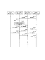
図10は、第1実施形態に係る中継制御方法の第1具体例を示す図である。本例は、UE100(第1下位ノード)が第1上位ノードを介してgNB200(第2上位ノード)と通信する場合を想定した動作例である。
FIG. 10 is a diagram showing a first specific example of the relay control method according to the first embodiment. This example is an operation example assuming a case where the UE 100 (first lower node) communicates with the gNB 200 (second upper node) via the first upper node.
図10に示すように、ステップS101において、第2上位ノードであるgNB200は、第1下位ノードであるUE100に対して一定期間を設定するための設定情報を第1上位ノード(IABノード300又は中継UE100-2)に送信する。設定情報は、gNB200から第1上位ノードを介してUE100に送信されるRRCメッセージ又はF1メッセージ(F1-APメッセージ)に含まれてもよい。
As shown in FIG. 10, in step S101, the gNB 200, which is the second upper node, provides the setting information for setting a certain period for the UE 100, which is the first lower node, to the first upper node (IAB node 300 or relay). It is transmitted to UE100-2). The setting information may be included in an RRC message or an F1 message (F1-AP message) transmitted from the gNB 200 to the UE 100 via the first higher-level node.
ここで、一定期間は、所定の時間単位の整数倍で表現されてもよい。例えば、設定情報は、一定期間に対応するサブフレーム数又は無線フレーム数(SFN値)を示す情報を含む。例えば、サブフレーム数を示す情報が4ビット情報である場合、“000”が4サブフレーム、“001”が8サブフレーム、“010”が16サブフレーム、“011”が32サブフレームといったように指定される。
Here, a certain period may be expressed as an integral multiple of a predetermined time unit. For example, the setting information includes information indicating the number of subframes or the number of radio frames (SFN value) corresponding to a certain period. For example, when the information indicating the number of subframes is 4-bit information, "000" is 4 subframes, "001" is 8 subframes, "010" is 16 subframes, "011" is 32 subframes, and so on. It is specified.
或いは、周期的な上りリンク無線リソース(周期的な上りリンク送信機会)がUE100に割当てられる前提下において、一定期間は、この割当て周期(「Configured Grant周期」と呼ばれることがある)の整数倍で表現されてもよい。例えば、Configured Grant周期がN回である場合、設定情報は、このNの値を示す情報を含む。
Alternatively, under the premise that periodic uplink radio resources (periodic uplink transmission opportunities) are allocated to the UE 100, a certain period is an integral multiple of this allocation cycle (sometimes referred to as "Configured Grant cycle"). It may be expressed. For example, when the Configured Grant period is N times, the setting information includes information indicating the value of N.
UE100が遠隔UE100-1であり、第1上位ノードが中継UE100-2である場合、一定期間は、次回のリソースプール(次回送信機会)の期間であってもよい。リソースプールは、遠隔UE100-1がデータ送信に利用可能な時間・周波数リソース群である。一定期間は、以後のN個のリソースプール(以後のN回の送信機会)の期間であってもよい。この場合、設定情報は、このNの値を示す情報を含む。
When the UE 100 is the remote UE 100-1 and the first upper node is the relay UE 100-2, the fixed period may be the period of the next resource pool (next transmission opportunity). The resource pool is a group of time / frequency resources that can be used by the remote UE 100-1 for data transmission. The fixed period may be the period of the subsequent N resource pools (the subsequent N transmission opportunities). In this case, the setting information includes information indicating the value of N.
本動作例では、gNB200が送信する設定情報を第1上位ノードがUE100に中継することで送信する一例について説明するが、第1上位ノードが自発的に設定情報をUE100に送信してもよい。
In this operation example, an example of transmitting the setting information transmitted by the gNB 200 by relaying the setting information to the UE 100 by the first upper node will be described, but the first higher node may voluntarily transmit the setting information to the UE 100.
ステップS102において、第1上位ノードは、ステップS101でgNB200から受信した設定情報をUE100に送信する。
In step S102, the first higher-level node transmits the setting information received from the gNB 200 in step S101 to the UE 100.
ステップS103において、UE100は、第1上位ノードから受信した設定情報に基づいて、以後の一定期間における送信見込みデータ量を予測する。UE100は、自身のアプリケーションレイヤから得られるアプリケーション情報及び直近の通信状況から得られる統計情報のうち少なくとも一方に基づいて送信見込みデータ量を予測してもよい。
In step S103, the UE 100 predicts the amount of expected transmission data in a certain period thereafter based on the setting information received from the first upper node. The UE 100 may predict the amount of expected transmission data based on at least one of the application information obtained from its own application layer and the statistical information obtained from the latest communication status.
ステップS104において、UE100は、ステップS103で予測した以後の一定期間における送信見込みデータ量を示すデータ量情報を第1上位ノードに送信する。UE100は、データ量情報を含むMAC制御要素を第1上位ノードに送信してもよいし、データ量情報を含むRRCメッセージを第1上位ノードに送信してもよい。UE100は、これらのメッセージに、gNB200から設定された一定期間を示す時間情報をさらに含めてもよい。或いは、UE100は、これらのメッセージの送信に先立って時間情報を第1上位ノードに送信してもよい。UE100は、データ量情報を含むRRCメッセージを、第1上位ノードを介してgNB200に送信してもよい。
In step S104, the UE 100 transmits data amount information indicating the amount of data expected to be transmitted in a certain period after the prediction in step S103 to the first upper node. The UE 100 may transmit a MAC control element including data amount information to the first higher-level node, or may send an RRC message including data amount information to the first higher-level node. The UE 100 may further include time information indicating a certain period set from the gNB 200 in these messages. Alternatively, the UE 100 may transmit time information to the first higher-level node prior to transmitting these messages. The UE 100 may transmit an RRC message including data amount information to the gNB 200 via the first higher-level node.
ステップS103及びS104において、UE100は、送信見込みデータ量をLCG(Logical Channel Group)ごとに予測し、データ量情報をLCG単位で通知してもよい。送信見込みデータ量を予測及び通知する単位は、LCG単位に限らず、論理チャネル単位であってもよいし、ベアラ単位であってもよい。
In steps S103 and S104, the UE 100 may predict the estimated transmission data amount for each LCG (Logical Channel Group) and notify the data amount information in LCG units. The unit for predicting and notifying the estimated transmission data amount is not limited to the LCG unit, but may be a logical channel unit or a bearer unit.
ステップS105において、第1上位ノードは、ステップS104でUE100から受信したデータ量情報に基づいて、gNB200に対して上りリンク無線リソースの割当てを要求する。例えば、第1上位ノードは、PUSCHリソースの割当てを要求するスケジューリング要求(SR)をPUCCH(Physical Uplink Control Channel)上でgNB200に送信してもよいし、UE100から受信したデータ量情報に基づくBSRをPUSCH上でgNB200に送信してもよい。
In step S105, the first higher-level node requests the gNB 200 to allocate uplink radio resources based on the data amount information received from the UE 100 in step S104. For example, the first higher-level node may send a scheduling request (SR) requesting the allocation of PUSCH resources to the gNB 200 on the PUCCH (Physical Uplink Control Channel), or may send a BSR based on the data amount information received from the UE 100. It may be transmitted to gNB 200 on PUSCH.
ステップS106において、第1上位ノードは、UE100から受信するデータ量情報に基づいて、無線リソースをUE100に割当てる。但し、UE100が遠隔UE100-1であり、第1上位ノードが中継UE100-2である場合、遠隔UE100-1に予めリソースプールが設定されていてもよい。例えば遠隔UE100-1がgNB200のカバレッジ内にある場合、リソースプールは、gNB200から遠隔UE100-1に設定されてもよい。遠隔UE100-1がgNB200のカバレッジ外にある場合、遠隔UE100-1は、自身に事前設定されているリソースプールを用いてもよい。
In step S106, the first higher-level node allocates the radio resource to the UE 100 based on the data amount information received from the UE 100. However, when the UE 100 is the remote UE 100-1 and the first higher-level node is the relay UE 100-2, a resource pool may be set in the remote UE 100-1 in advance. For example, if the remote UE 100-1 is within the coverage of the gNB 200, the resource pool may be set from the gNB 200 to the remote UE 100-1. If the remote UE 100-1 is outside the coverage of the gNB 200, the remote UE 100-1 may use its own preset resource pool.
ステップS107において、gNB200は、ステップS107で第1上位ノードから受信した割当要求に基づいて、上りリンク無線リソースを第1上位ノードに割当てる。
In step S107, the gNB 200 allocates the uplink radio resource to the first higher node based on the allocation request received from the first higher node in step S107.
ステップS108において、UE100は、ステップS106で上位ノードから割当てられた無線リソース又は予め設定されているリソースプールを用いて、PUSCH又はPSSCH(Physical Sidelink Shared Channel)上でデータを第1上位ノードに送信する。
In step S108, the UE 100 transmits data to the first higher-level node on the PUSCH or PSCH (Physical Sidelink Shared Channel) using the radio resources allocated from the higher-level node or the preset resource pool in step S106. ..
ステップS109において、第1上位ノードは、ステップS107でgNB200から割当てられた上りリンク無線リソースを用いて、ステップS108でUE100から受信したデータをPUSCH上でgNB200に送信する。
In step S109, the first higher-level node transmits the data received from the UE 100 in step S108 to the gNB 200 on the PUSCH using the uplink radio resource allocated from the gNB 200 in step S107.
図11は、第1実施形態に係る中継制御方法の第2具体例を示す図である。本例は、UE100(第2下位ノード)がIABノード300-2(第1下位ノード)及びIABノード300-1(第1上位ノード)を介してgNB200(第2上位ノード)と通信する場合を想定した動作例である(図1参照)。
FIG. 11 is a diagram showing a second specific example of the relay control method according to the first embodiment. In this example, the UE 100 (second lower node) communicates with the gNB 200 (second upper node) via the IAB node 300-2 (first lower node) and the IAB node 300-1 (first upper node). This is an assumed operation example (see FIG. 1).
図11に示すように、ステップS111及びS112は、上述した動作例1と同様である。
As shown in FIG. 11, steps S111 and S112 are the same as the operation example 1 described above.
ステップS113において、UE100は、BSRをIABノード300-2に送信する。
In step S113, the UE 100 transmits the BSR to the IAB node 300-2.
ステップS114において、IABノード300-2は、設定情報に基づいて、以後の一定期間における送信見込みデータ量を予測する。IABノード300-2は、ステップS113でUE100から受信したBSRに基づいて、以後の一定期間における送信見込みデータ量を予測してもよい。
In step S114, the IAB node 300-2 predicts the amount of expected transmission data in a certain period thereafter based on the setting information. The IAB node 300-2 may predict the amount of expected transmission data in a certain period thereafter based on the BSR received from the UE 100 in step S113.
ステップS115において、IABノード300-2は、ステップS114で予測した以後の一定期間における送信見込みデータ量を示すデータ量情報をIABノード300-1に送信する。IABノード300-2は、データ量情報を含むMAC制御要素をIABノード300-1に送信してもよいし、データ量情報を含むRRCメッセージをIABノード300-1に送信してもよい。IABノード300-2は、これらのメッセージに、設定された一定期間を示す時間情報をさらに含めてもよい。或いは、IABノード300-2は、これらのメッセージの送信に先立って時間情報をIABノード300-1に送信してもよい。IABノード300-2は、データ量情報を含むRRCメッセージ又はF1-APメッセージを、IABノード300-1を介してgNB200に送信してもよい。
In step S115, the IAB node 300-2 transmits data amount information indicating the amount of expected transmission data in a certain period after the prediction in step S114 to the IAB node 300-1. The IAB node 300-2 may transmit a MAC control element including data amount information to the IAB node 300-1, or may transmit an RRC message including data amount information to the IAB node 300-1. The IAB node 300-2 may further include time information indicating a set fixed period in these messages. Alternatively, the IAB node 300-2 may transmit the time information to the IAB node 300-1 prior to the transmission of these messages. The IAB node 300-2 may transmit an RRC message or an F1-AP message including data amount information to the gNB 200 via the IAB node 300-1.
ステップS114及びS115において、IABノード300-2は、送信見込みデータ量をLCGごとに予測し、データ量情報をLCG単位で通知してもよい。送信見込みデータ量を予測及び通知する単位は、LCG単位に限らず、論理チャネル単位であってもよいし、ベアラ単位であってもよい。
In steps S114 and S115, the IAB node 300-2 may predict the estimated transmission data amount for each LCG and notify the data amount information in the LCG unit. The unit for predicting and notifying the estimated transmission data amount is not limited to the LCG unit, but may be a logical channel unit or a bearer unit.
ステップS116において、IABノード300-2は、ステップS113でUE100から受信したBSRに基づいて、上りリンク無線リソースをUE100に割当てる。
In step S116, the IAB node 300-2 allocates the uplink radio resource to the UE 100 based on the BSR received from the UE 100 in step S113.
ステップS117において、IABノード300-1は、ステップS115でIABノード300-2から受信したデータ量情報に基づいて、gNB200に対して上りリンク無線リソースの割当てを要求する。例えば、IABノード300-1は、PUSCHリソースの割当てを要求するSRをPUCCH上でgNB200に送信してもよいし、ステップS115でIABノード300-2から受信したデータ量情報に基づくBSRをPUSCH上でgNB200に送信してもよい。
In step S117, the IAB node 300-1 requests the gNB 200 to allocate uplink radio resources based on the data amount information received from the IAB node 300-2 in step S115. For example, the IAB node 300-1 may transmit the SR requesting the allocation of the PUSCH resource to the gNB 200 on the PUCCH, or the BSR based on the data amount information received from the IAB node 300-2 in step S115 on the PUSCH. May be sent to gNB200.
ステップS118において、IABノード300-1は、ステップS115でIABノード300-2から受信したデータ量情報に基づいて、上りリンク無線リソースをIABノード300-2に割当てる。
In step S118, the IAB node 300-1 allocates the uplink radio resource to the IAB node 300-2 based on the data amount information received from the IAB node 300-2 in step S115.
ステップS119において、gNB200は、ステップS117でIABノード300-1から受信した割当要求に基づいて、上りリンク無線リソースをIABノード300-1に割当てる。
In step S119, the gNB 200 allocates the uplink radio resource to the IAB node 300-1 based on the allocation request received from the IAB node 300-1 in step S117.
ステップS120において、UE100は、ステップS116でIABノード300-2から割当てられた上りリンク無線リソースを用いて、データをPUSCH上でIABノード300-2に送信する。
In step S120, the UE 100 transmits data to the IAB node 300-2 on the PUSCH using the uplink radio resource allocated from the IAB node 300-2 in step S116.
ステップS121において、IABノード300-2は、ステップS118でIABノード300-1から割当てられた上りリンク無線リソースを用いて、UE100からのデータをPUSCH上でIABノード300-1に送信する。
In step S121, the IAB node 300-2 transmits data from the UE 100 to the IAB node 300-1 on the PUSCH using the uplink radio resource allocated from the IAB node 300-1 in step S118.
ステップS122において、IABノード300-1は、ステップS119でgNB200から割当てられた上りリンク無線リソースを用いて、IABノード300-2からのデータをPUSCH上でgNB200に送信する。
In step S122, the IAB node 300-1 transmits the data from the IAB node 300-2 to the gNB 200 on the PUSCH using the uplink radio resource allocated from the gNB 200 in step S119.
[第2実施形態]
次に、第2実施形態について、第1実施形態との相違点を主として説明する。 [Second Embodiment]
Next, the differences between the second embodiment and the first embodiment will be mainly described.
次に、第2実施形態について、第1実施形態との相違点を主として説明する。 [Second Embodiment]
Next, the differences between the second embodiment and the first embodiment will be mainly described.
図12は、第2実施形態に係る移動通信システム1の構成例を示す図である。図12に示すように、第2実施形態において、中継ノードの一例であるIABノード300がハンドオーバを行うことを想定する。但し、中継ノードは、上述した中継UE100-2であってもよい。図12に示すように、gNB200SからgNB200Tに対してIABノード300がハンドオーバを行う。
FIG. 12 is a diagram showing a configuration example of the mobile communication system 1 according to the second embodiment. As shown in FIG. 12, in the second embodiment, it is assumed that the IAB node 300, which is an example of the relay node, performs the handover. However, the relay node may be the relay UE 100-2 described above. As shown in FIG. 12, the IAB node 300 performs a handover from the gNB 200S to the gNB 200T.
各gNB200は、CU及びDUを有する。CU及びDUは、F1インターフェイスを介して互いに接続される。CUは、上位レイヤ(RRCレイヤ及びPDCPレイヤ)を有する。DUは、下位レイヤ(RLCレイヤ、MACレイヤ、及びPHYレイヤ)を有する。gNB200SのCUとgNB200TのCUとの間には、基地局間インターフェイスであるXnインターフェイスが存在する。gNB200SのCUと5Gコアネットワーク(5GC)10との間にNGインターフェイスが存在し、gNB200SのCUとgNB200TのCUとの間に5GC10を介する間接的な接続が確立されていてもよい。以下において、gNB200SからgNB200Tに対してIABノード300のハンドオーバを行うシナリオを「IABノード300のインターCUハンドオーバ」と呼ぶ。
Each gNB 200 has a CU and a DU. The CU and DU are connected to each other via the F1 interface. The CU has an upper layer (RRC layer and PDCP layer). The DU has lower layers (RLC layer, MAC layer, and PHY layer). Between the CU of gNB200S and the CU of gNB200T, there is an Xn interface which is an interface between base stations. An NG interface may exist between the CU of the gNB200S and the 5G core network (5GC) 10, and an indirect connection via the 5GC10 may be established between the CU of the gNB200S and the CU of the gNB200T. In the following, a scenario in which the IAB node 300 is handed over from the gNB 200S to the gNB 200T will be referred to as an “inter-CU handover of the IAB node 300”.
図12において、gNB200SからgNB200Tに対してIABノード300のインターCUハンドオーバを行うシナリオを例示しているが、gNB200Sの配下の装置(gNB200Sの下位のIABノード)から、gNB200Tの配下の装置(gNB200Tの下位のIABノード)に対して、IABノード300のインターCUハンドオーバを行ってもよい。例えば、IABノード300のインターCUハンドオーバ前において、IABノード300とgNB200Sとの間の経路上に1つ又は複数のIABノードが存在してもよい。IABノード300のインターCUハンドオーバ後において、IABノード300とgNB200Tとの間の経路上に1つ又は複数のIABノードが存在してもよい。
FIG. 12 illustrates a scenario in which the inter-CU handover of the IAB node 300 is performed from the gNB 200S to the gNB 200T. From the device under the gNB 200S (IAB node lower than the gNB 200S), the device under the gNB 200T (gNB 200T) The inter-CU handover of the IAB node 300 may be performed for the lower IAB node). For example, one or more IAB nodes may be present on the path between the IAB node 300 and the gNB 200S before the inter-CU handover of the IAB node 300. After the inter-CU handover of the IAB node 300, one or more IAB nodes may be present on the path between the IAB node 300 and the gNB 200T.
また、図12において、IABノード300の配下の下位ノードとして、複数のUE100(UE100a乃至100c)を例示している。IABノード300の配下に下位のIABノードが存在してもよい。すなわち、IABノード300の配下の下位ノードは、UE100及び下位のIABノードのうち少なくとも一方である。以下においては、IABノード300の配下の下位ノードがUE100である一例について主として説明する。UE100は、Uuインターフェイスを介してIABノード300のDUと接続される。
Further, in FIG. 12, a plurality of UEs 100 (UE100a to 100c) are illustrated as subordinate nodes under the IAB node 300. A lower IAB node may exist under the IAB node 300. That is, the lower node under the IAB node 300 is at least one of the UE 100 and the lower IAB node. In the following, an example in which the lower node under the IAB node 300 is the UE 100 will be mainly described. The UE 100 is connected to the DU of the IAB node 300 via the Uu interface.
IABノード300は、MT及びDUを有する。IABノード300のMTは、Uuインターフェイスを介してgNB200のDUと接続される。IABノード300のMTとgNB200のDUとの間のUuインターフェイスは、バックホールリンクとして用いられる。また、IABノード300は、BAPレイヤを有する。BAPレイヤはMTとDUとの間の中間レイヤに位置付けられてもよいし、BAPレイヤの少なくとも一部がMT及び/又はDUに組み込まれていてもよい。
IAB node 300 has MT and DU. The MT of the IAB node 300 is connected to the DU of the gNB 200 via the Uu interface. The Uu interface between the MT of the IAB node 300 and the DU of the gNB 200 is used as a backhaul link. In addition, the IAB node 300 has a BAP layer. The BAP layer may be positioned as an intermediate layer between the MT and DU, or at least a portion of the BAP layer may be incorporated into the MT and / or DU.
UE100及びMTのそれぞれは、上位・下位レイヤ(RRCレイヤ、PDCPレイヤ、RLCレイヤ、MACレイヤ、及びPHYレイヤ)を有する。各UE100の下位レイヤ(RLCレイヤ、MACレイヤ、及びPHYレイヤ)は、IABノード300のDU(RLCレイヤ、MACレイヤ、及びPHYレイヤ)との通信を行う。一方、各UE100の上位レイヤ(RRCレイヤ及びPDCPレイヤ)は、gNB200のCU(RRCレイヤ及びPDCPレイヤ)との通信を行う。
Each of UE100 and MT has upper and lower layers (RRC layer, PDCP layer, RLC layer, MAC layer, and PHY layer). The lower layers (RLC layer, MAC layer, and PHY layer) of each UE 100 communicate with the DU (RLC layer, MAC layer, and PHY layer) of the IAB node 300. On the other hand, the upper layer (RRC layer and PDCP layer) of each UE 100 communicates with the CU (RRC layer and PDCP layer) of gNB200.
図12に示す例において、IABノード300は、ハンドオーバ前において、各UE100から受信するデータをgNB200Sに中継する。ここで、各UE100から受信するデータは、UE100のPDCPレイヤで暗号化されている。gNB200SのPDCPレイヤは、UE100と共有する鍵情報を用いて、IABノード300が中継したデータを復号(暗号解除)する。
In the example shown in FIG. 12, the IAB node 300 relays the data received from each UE 100 to the gNB 200S before the handover. Here, the data received from each UE 100 is encrypted by the PDCP layer of the UE 100. The PDCP layer of the gNB 200S decrypts (decrypts) the data relayed by the IAB node 300 using the key information shared with the UE 100.
ここで、IABノード300がインターCUハンドオーバを行う場合、IABノード300がUE100から受信して保持している(バッファしている)データをgNB200Tに中継すると、gNB200TのPDCPレイヤが鍵情報を有していないため、このデータを復号できない。このため、gNB200Tにおいてデータを破棄することになる。その結果、バッファしているデータをgNB200Tに中継しても無駄になり、リソースの無駄遣いを引き起こす。第2実施形態においては、このような無駄な中継を防止することで、リソースの無駄遣いを防止可能とする。
Here, when the IAB node 300 performs the inter-CU handover, when the data received by the IAB node 300 from the UE 100 and held (buffered) is relayed to the gNB 200T, the PDCP layer of the gNB 200T has the key information. This data cannot be decrypted because it is not. Therefore, the data will be discarded in the gNB 200T. As a result, even if the buffered data is relayed to the gNB200T, it is wasted, causing a waste of resources. In the second embodiment, by preventing such useless relaying, it is possible to prevent wasteful use of resources.
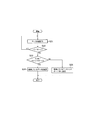
図13は、第2実施形態に係る中継制御方法を示す図である。第2実施形態に係る中継制御方法は、1つ又は複数の中継ノードがUE100からgNB200へのデータを中継する移動通信システム1において用いる方法である。
FIG. 13 is a diagram showing a relay control method according to the second embodiment. The relay control method according to the second embodiment is a method used in the mobile communication system 1 in which one or more relay nodes relay data from the UE 100 to the gNB 200.
図13に示すように、ステップS21において、1つ又は複数の中継ノードに含まれる第1中継ノードは、データ中継動作を行う。第1中継ノードは、IABノード300に限らず、中継UE100-2であってもよい。
As shown in FIG. 13, in step S21, the first relay node included in one or more relay nodes performs a data relay operation. The first relay node is not limited to the IAB node 300, and may be a relay UE 100-2.
具体的には、第1中継ノードは、第1中継ノードよりも下位の下位ノードからデータを受信する。下位ノードは、UE100であってもよいし、下位のIABノード300であってもよい。第1中継ノードは、下位ノードから受信したデータを、第1中継ノードよりも上位の上位ノードへの当該データの送信が完了するまで保持(バッファ)する。上位ノードは、gNB200であってもよいし、上位のIABノード300であってもよい。
Specifically, the first relay node receives data from a lower node lower than the first relay node. The lower node may be the UE 100 or the lower IAB node 300. The first relay node holds (buffers) the data received from the lower node until the transmission of the data to the upper node higher than the first relay node is completed. The upper node may be the gNB 200 or the upper IAB node 300.
ステップS22において、第1中継ノードは、ハンドオーバを行うか否かを判定する。例えば、第1中継ノードは、上位ノードからハンドオーバ指示を受信した場合、ハンドオーバを行うと判定する。ハンドオーバを行わない場合(ステップS22:NO)、第1中継ノードは、データ中継動作を継続する(ステップS21)。
In step S22, the first relay node determines whether or not to perform handover. For example, when the first relay node receives the handover instruction from the higher-level node, it determines that the handover is performed. When the handover is not performed (step S22: NO), the first relay node continues the data relay operation (step S21).
一方、ハンドオーバを行う場合(ステップS22:YES)、ステップS23において、第1中継ノードは、ハンドオーバがインターCUハンドオーバであるか否かを判定する。インターCUハンドオーバは、第1中継ノードによる、gNB200S(第1基地局)とは異なるgNB200T(第2基地局)又はgNB200Tの配下の第2中継ノードへのハンドオーバである。
On the other hand, when performing a handover (step S22: YES), in step S23, the first relay node determines whether or not the handover is an inter-CU handover. The inter-CU handover is a handover by the first relay node to a second relay node under the gNB200T (second base station) or gNB200T, which is different from the gNB200S (first base station).
例えば、gNB200T又は第2中継ノードは、gNB200Tに関する識別子を送信(例えば、システム情報の一部としてブロードキャスト)してもよい。第1中継ノードは、gNB200T又は第2中継ノードから受信する識別子に基づいて、インターCUハンドオーバ(互いに異なるgNB200間でのハンドオーバ)を検知してもよい。具体的には、第1中継ノードは、ハンドオーバ前に把握しているgNB200Sに関する識別子と、ハンドオーバ先の候補から受信する識別子とが一致するか否かによりインターCUハンドオーバを検知する。
For example, the gNB200T or the second relay node may transmit an identifier relating to the gNB200T (for example, broadcast as part of system information). The first relay node may detect an inter-CU handover (handover between different gNB 200s) based on the identifier received from the gNB 200T or the second relay node. Specifically, the first relay node detects the inter-CU handover depending on whether or not the identifier related to the gNB 200S grasped before the handover matches the identifier received from the candidate of the handover destination.
或いは、gNB200Sは、インターCUハンドオーバに関する情報を含むハンドオーバ指示を第1中継ノードに送信してもよい。インターCUハンドオーバに関する情報は、ハンドオーバ先のgNB200に関する識別子であってもよい。第1中継ノードは、ハンドオーバ指示に含まれる情報に基づいて、インターCUハンドオーバを検知してもよい。
Alternatively, the gNB 200S may transmit a handover instruction including information regarding the inter-CU handover to the first relay node. The information regarding the inter-CU handover may be an identifier regarding the gNB 200 of the handover destination. The first relay node may detect the inter-CU handover based on the information included in the handover instruction.
或いは、第1中継ノードは、ハンドオーバ前後における自身のPDCPレイヤの状態に基づいてインターCUハンドオーバを検知してもよい。例えば、第1中継ノードは、PDCPレイヤの再確立が発生したことに応じてインターCUハンドオーバを検知する。
Alternatively, the first relay node may detect the inter-CU handover based on the state of its own PDCP layer before and after the handover. For example, the first relay node detects the inter-CU handover in response to the re-establishment of the PDCP layer.
ハンドオーバがインターCUハンドオーバである場合(ステップS23:YES)、ステップS24において、第1中継ノードは、このハンドオーバの実行に応じて、ステップS21で保持したデータ(すなわち、バッファしている上りリンクデータ)を破棄する。この場合、第1中継ノードは、バッファしている上りリンクデータをハンドオーバ先に対して中継しない。
When the handover is an inter-CU handover (step S23: YES), in step S24, the first relay node responds to the execution of this handover with the data held in step S21 (that is, the buffered uplink data). Is destroyed. In this case, the first relay node does not relay the buffered uplink data to the handover destination.
ハンドオーバがインターCUハンドオーバではない場合(ステップS23:NO)、ステップS25において、第1中継ノードは、このハンドオーバの実行に応じて、バッファしている上りリンクデータをハンドオーバ先に送信(中継)する。なお、ハンドオーバがインターCUハンドオーバではない場合とは、第1中継ノードが、gNB200S又はgNB200Sの配下の中継ノードへのハンドオーバを実行する場合をいう。
When the handover is not an inter-CU handover (step S23: NO), in step S25, the first relay node transmits (relays) the buffered uplink data to the handover destination in response to the execution of this handover. The case where the handover is not an inter-CU handover means that the first relay node executes the handover to the relay node under the gNB200S or gNB200S.
[その他の実施形態]
上述した実施形態において、移動通信システム1が5G移動通信システムである一例について主として説明した。しかしながら、移動通信システム1における基地局はLTE基地局であるeNBであってもよい。また、移動通信システム1におけるコアネットワークはEPC(Evolved Packet Core)であってもよい。さらに、gNBがEPCに接続することもでき、eNBが5GCに接続することもでき、gNBとeNBとが基地局間インターフェイス(Xnインターフェイス、X2インターフェイス)を介して接続されてもよい。 [Other Embodiments]
In the above-described embodiment, an example in which themobile communication system 1 is a 5G mobile communication system has been mainly described. However, the base station in the mobile communication system 1 may be an eNB which is an LTE base station. Further, the core network in the mobile communication system 1 may be an EPC (Evolved Packet Core). Further, the gNB may be connected to the EPC, the eNB may be connected to the 5GC, and the gNB and the eNB may be connected via the inter-base station interface (Xn interface, X2 interface).
上述した実施形態において、移動通信システム1が5G移動通信システムである一例について主として説明した。しかしながら、移動通信システム1における基地局はLTE基地局であるeNBであってもよい。また、移動通信システム1におけるコアネットワークはEPC(Evolved Packet Core)であってもよい。さらに、gNBがEPCに接続することもでき、eNBが5GCに接続することもでき、gNBとeNBとが基地局間インターフェイス(Xnインターフェイス、X2インターフェイス)を介して接続されてもよい。 [Other Embodiments]
In the above-described embodiment, an example in which the
上述した実施形態に係る各処理をコンピュータに実行させるプログラムが提供されてもよい。また、プログラムは、コンピュータ読取り可能媒体に記録されていてもよい。コンピュータ読取り可能媒体を用いれば、コンピュータにプログラムをインストールすることが可能である。ここで、プログラムが記録されたコンピュータ読取り可能媒体は、非一過性の記録媒体であってもよい。非一過性の記録媒体は、特に限定されるものではないが、例えば、CD-ROMやDVD-ROM等の記録媒体であってもよい。UE100、gNB200、又はIABノード300が行う各処理を実行するためのプログラムを記憶するメモリ及びメモリに記憶されたプログラムを実行するプロセッサによって構成されるチップセットが提供されてもよい。
A program for causing a computer to execute each process according to the above-described embodiment may be provided. The program may also be recorded on a computer-readable medium. Computer-readable media allow you to install programs on your computer. Here, the computer-readable medium on which the program is recorded may be a non-transient recording medium. The non-transient recording medium is not particularly limited, but may be, for example, a recording medium such as a CD-ROM or a DVD-ROM. A chipset composed of a memory for storing a program for executing each process performed by the UE 100, the gNB 200, or the IAB node 300 and a processor for executing the program stored in the memory may be provided.
本願は、日本国特許出願第2020-021900号(2020年2月12日出願)の優先権を主張し、その内容の全てが本願明細書に組み込まれている。
The present application claims the priority of Japanese Patent Application No. 2020-021900 (filed on February 12, 2020), and all of its contents are incorporated in the specification of the present application.
Claims (14)
- 1つ又は複数の中継ノードがユーザ装置から基地局へのデータを中継する移動通信システムにおいて用いる中継制御方法であって、
第1下位ノードが、前記第1下位ノードから前記第1下位ノードよりも上位の第1上位ノードに対して以後の一定期間内に送信する見込みのデータ量である送信見込みデータ量を予測することと、
前記第1下位ノードが、前記送信見込みデータ量を示すデータ量情報を前記第1上位ノードに送信することと、を有し、
前記第1下位ノードは、前記1つ又は複数の中継ノードに含まれる中継ノード、又は前記ユーザ装置であり、
前記第1上位ノードは、前記1つ又は複数の中継ノードに含まれる中継ノード、又は前記基地局である
中継制御方法。 A relay control method used in a mobile communication system in which one or more relay nodes relay data from a user device to a base station.
Predicting the estimated transmission data amount, which is the amount of data that the first lower node is expected to transmit from the first lower node to the first upper node higher than the first lower node within a certain period thereafter. When,
The first lower node has data amount information indicating the expected transmission amount of data to be transmitted to the first upper node.
The first lower node is a relay node included in the one or more relay nodes, or the user device.
The relay control method in which the first higher-level node is a relay node included in the one or more relay nodes, or the base station. - 前記第1上位ノードが、前記第1下位ノードに対して、前記一定期間を設定する設定情報を送信することを有し、
前記予測することは、前記設定情報に基づいて、前記一定期間における前記送信見込みデータ量を予測することを含む
請求項1に記載の中継制御方法。 The first upper node has to transmit the setting information for setting the fixed period to the first lower node.
The relay control method according to claim 1, wherein the prediction includes predicting the amount of expected transmission data in the fixed period based on the setting information. - 前記第1下位ノードが、前記第1上位ノードに対して、前記一定期間を示す時間情報を送信することを有する
請求項1又は2に記載の中継制御方法。 The relay control method according to claim 1 or 2, wherein the first lower node transmits time information indicating the fixed period to the first upper node. - 前記第1上位ノードが、前記第1下位ノードから受信する前記データ量情報に基づいて、上りリンク無線リソースを前記第1下位ノードに割当てることを有する
請求項1乃至3のいずれか1項に記載の中継制御方法。 The invention according to any one of claims 1 to 3, wherein the first upper node allocates uplink radio resources to the first lower node based on the data amount information received from the first lower node. Relay control method. - 前記第1上位ノードが前記中継ノードであって、
前記第1上位ノードが、前記第1下位ノードから受信する前記データ量情報に基づいて、前記第1上位ノードよりもさらに上位の第2上位ノードに対して、上りリンク無線リソースの割当てを要求することをさらに有する
請求項1乃至4のいずれか1項に記載の中継制御方法。 The first higher-level node is the relay node,
Based on the data amount information received from the first lower node, the first upper node requests the second upper node further higher than the first upper node to allocate uplink radio resources. The relay control method according to any one of claims 1 to 4, further comprising the above. - 前記第1下位ノードが前記中継ノードであって、
前記データ量情報を送信することは、第1イベント又は第2イベントの発生に応じて、前記第1下位ノードから前記第1上位ノードに対して前記データ量情報を送信することを含み、
前記第1イベントは、前記第1下位ノードよりもさらに下位の第2下位ノードから前記第1下位ノードがバッファ状態報告を受信したというイベントであり、
前記第2イベントは、前記第1下位ノードが前記第2下位ノードに対して上りリンク無線リソースを割当てたというイベントである
請求項1乃至5のいずれか1項に記載の中継制御方法。 The first lower node is the relay node,
The transmission of the data amount information includes transmitting the data amount information from the first lower node to the first upper node in response to the occurrence of the first event or the second event.
The first event is an event in which the first lower node receives a buffer status report from a second lower node further lower than the first lower node.
The relay control method according to any one of claims 1 to 5, wherein the second event is an event in which the first lower node allocates uplink radio resources to the second lower node. - 前記第1下位ノードが前記ユーザ装置であり、且つ、前記第1上位ノードが前記中継ノードとして動作する中継ユーザ装置であって、
前記データ量情報を送信することは、前記第1下位ノードから前記第1上位ノードに対して、前記データ量情報をサイドリンク上で送信することを含む
請求項1乃至6のいずれか1項に記載の中継制御方法。 The first lower node is the user device, and the first upper node is a relay user device that operates as the relay node.
The transmission of the data amount information according to any one of claims 1 to 6, which includes transmitting the data amount information from the first lower node to the first upper node on a side link. The relay control method described. - 前記データ量情報は、前記一定期間が経過するまでの間の1つ又は複数の送信機会における前記送信見込みデータ量を示す
請求項1乃至7のいずれか1項に記載の中継制御方法。 The relay control method according to any one of claims 1 to 7, wherein the data amount information indicates the amount of expected transmission data in one or a plurality of transmission opportunities until a certain period of time elapses. - 1つ又は複数の中継ノードがユーザ装置から基地局へのデータを中継する移動通信システムにおいて、第1下位ノードとして動作する通信ノードであって、
前記第1下位ノードから前記第1下位ノードよりも上位の第1上位ノードに対して以後の一定期間内に送信する見込みのデータ量である送信見込みデータ量を予測する制御部と、
前記送信見込みデータ量を示すデータ量情報を前記第1上位ノードに送信する送信部と、を有し、
前記第1下位ノードは、前記1つ又は複数の中継ノードに含まれる中継ノード、又は前記ユーザ装置であり、
前記第1上位ノードは、前記1つ又は複数の中継ノードに含まれる中継ノード、又は前記基地局である
通信ノード。 A communication node that operates as a first lower node in a mobile communication system in which one or more relay nodes relay data from a user device to a base station.
A control unit that predicts the amount of data expected to be transmitted from the first lower node to the first upper node higher than the first lower node, which is the amount of data expected to be transmitted within a certain period thereafter.
It has a transmission unit that transmits data amount information indicating the expected transmission amount of data to the first higher-level node.
The first lower node is a relay node included in the one or more relay nodes, or the user device.
The first higher-level node is a relay node included in the one or more relay nodes, or a communication node that is the base station. - 1つ又は複数の中継ノードがユーザ装置から第1基地局へのデータを中継する移動通信システムにおいて用いる中継制御方法であって、
前記1つ又は複数の中継ノードに含まれる第1中継ノードが、前記第1中継ノードよりも下位の下位ノードからデータを受信することと、
前記第1中継ノードが、前記下位ノードから受信したデータを、前記第1中継ノードよりも上位の上位ノードへの当該受信したデータの送信が完了するまで保持することと、
前記第1中継ノードが、前記第1基地局とは異なる第2基地局又は前記第2基地局の配下の第2中継ノードへのハンドオーバを実行することと、
前記第1中継ノードが、前記ハンドオーバの実行に応じて、前記保持しているデータを破棄することと、を有する
中継制御方法。 A relay control method used in a mobile communication system in which one or more relay nodes relay data from a user device to a first base station.
The first relay node included in the one or more relay nodes receives data from a lower node lower than the first relay node.
The first relay node holds the data received from the lower node until the transmission of the received data to the upper node higher than the first relay node is completed.
The first relay node executes a handover to a second base station different from the first base station or a second relay node under the control of the second base station.
A relay control method in which the first relay node discards the held data in response to the execution of the handover. - 前記第2基地局又は前記第2中継ノードが、前記第2基地局に関する識別子を送信することと、
前記第1中継ノードが、前記第2基地局又は前記第2中継ノードから受信する前記識別子に基づいて、互いに異なる基地局間での前記ハンドオーバを検知することと、を有する
請求項10に記載の中継制御方法。 When the second base station or the second relay node transmits an identifier relating to the second base station,
The tenth aspect of the present invention, wherein the first relay node detects the handover between different base stations based on the identifier received from the second relay node or the second relay node. Relay control method. - 前記第1基地局が、互いに異なる基地局間での前記ハンドオーバに関する情報を含むハンドオーバ指示を前記第1中継ノードに送信することと、
前記第1中継ノードが、前記ハンドオーバ指示に含まれる前記情報に基づいて、互いに異なる基地局間での前記ハンドオーバを検知することと、を有する
請求項10に記載の中継制御方法。 The first base station transmits a handover instruction including information on the handover between different base stations to the first relay node.
The relay control method according to claim 10, wherein the first relay node detects the handover between different base stations based on the information included in the handover instruction. - 前記第1中継ノードが、前記第1基地局又は前記第1基地局の配下の中継ノードへのハンドオーバを実行した場合、当該ハンドオーバの実行に応じて、前記保持しているデータをハンドオーバ先に送信することを有する
請求項10乃至12のいずれか1項に記載の中継制御方法。 When the first relay node executes a handover to the first base station or a relay node under the control of the first base station, the held data is transmitted to the handover destination in response to the execution of the handover. The relay control method according to any one of claims 10 to 12, wherein the relay control method is to be performed. - 1つ又は複数の中継ノードがユーザ装置から第1基地局へのデータを中継する移動通信システムにおいて、前記1つ又は複数の中継ノードに含まれる第1中継ノードとして動作する通信ノードであって、
前記第1中継ノードよりも下位の下位ノードからデータを受信する受信部と、
前記下位ノードから受信したデータを、前記第1中継ノードよりも上位の上位ノードへの当該受信したデータの送信が完了するまで保持する制御部と、を有し、
前記制御部は、前記第1基地局とは異なる第2基地局又は前記第2基地局の配下の第2中継ノードへのハンドオーバを前記第1中継ノードが実行することに応じて、前記保持しているデータを破棄する
通信ノード。 A communication node that operates as a first relay node included in the one or more relay nodes in a mobile communication system in which one or more relay nodes relay data from a user device to a first base station.
A receiving unit that receives data from a lower node lower than the first relay node, and
It has a control unit that holds the data received from the lower node until the transmission of the received data to the upper node higher than the first relay node is completed.
The control unit holds the second base station different from the first base station or the second relay node under the control of the second base station in response to the first relay node performing the handover. A communication node that discards data.
Priority Applications (3)
| Application Number | Priority Date | Filing Date | Title |
|---|---|---|---|
| JP2022500379A JP7321352B2 (en) | 2020-02-12 | 2021-02-05 | Relay control method and communication node |
| EP21753558.2A EP4087302A4 (en) | 2020-02-12 | 2021-02-05 | Relay control method and communication node |
| US17/885,315 US20220386309A1 (en) | 2020-02-12 | 2022-08-10 | Relay control method and communication node |
Applications Claiming Priority (2)
| Application Number | Priority Date | Filing Date | Title |
|---|---|---|---|
| JP2020021900 | 2020-02-12 | ||
| JP2020-021900 | 2020-02-12 |
Related Child Applications (1)
| Application Number | Title | Priority Date | Filing Date |
|---|---|---|---|
| US17/885,315 Continuation US20220386309A1 (en) | 2020-02-12 | 2022-08-10 | Relay control method and communication node |
Publications (1)
| Publication Number | Publication Date |
|---|---|
| WO2021161925A1 true WO2021161925A1 (en) | 2021-08-19 |
Family
ID=77292274
Family Applications (1)
| Application Number | Title | Priority Date | Filing Date |
|---|---|---|---|
| PCT/JP2021/004381 WO2021161925A1 (en) | 2020-02-12 | 2021-02-05 | Relay control method and communication node |
Country Status (4)
| Country | Link |
|---|---|
| US (1) | US20220386309A1 (en) |
| EP (1) | EP4087302A4 (en) |
| JP (1) | JP7321352B2 (en) |
| WO (1) | WO2021161925A1 (en) |
Cited By (1)
| Publication number | Priority date | Publication date | Assignee | Title |
|---|---|---|---|---|
| WO2024011490A1 (en) * | 2022-07-14 | 2024-01-18 | Qualcomm Incorporated | Resource scheduling for a relay-based sidelink network |
Families Citing this family (1)
| Publication number | Priority date | Publication date | Assignee | Title |
|---|---|---|---|---|
| US20220124573A1 (en) * | 2020-10-20 | 2022-04-21 | Mediatek Inc. | Apparatuses and methods for recovering from sidelink relay failure |
Citations (3)
| Publication number | Priority date | Publication date | Assignee | Title |
|---|---|---|---|---|
| WO2018174184A1 (en) * | 2017-03-24 | 2018-09-27 | 京セラ株式会社 | Wireless terminal, processor, and base station |
| JP2020021900A (en) | 2018-08-03 | 2020-02-06 | 株式会社タムラ製作所 | Curable resin composition for inkjet and printed wiring board |
| WO2021025145A1 (en) * | 2019-08-07 | 2021-02-11 | 京セラ株式会社 | Communication control method and relay device |
Family Cites Families (2)
| Publication number | Priority date | Publication date | Assignee | Title |
|---|---|---|---|---|
| US11395320B2 (en) * | 2018-05-18 | 2022-07-19 | Nokia Solutions And Networks Oy | Predictive scheduling request or buffer status report for wireless backhauling |
| US11606715B2 (en) * | 2018-08-02 | 2023-03-14 | Lg Electronics Inc. | Method of transmitting buffer status report, and device therefor |
-
2021
- 2021-02-05 EP EP21753558.2A patent/EP4087302A4/en active Pending
- 2021-02-05 JP JP2022500379A patent/JP7321352B2/en active Active
- 2021-02-05 WO PCT/JP2021/004381 patent/WO2021161925A1/en unknown
-
2022
- 2022-08-10 US US17/885,315 patent/US20220386309A1/en active Pending
Patent Citations (3)
| Publication number | Priority date | Publication date | Assignee | Title |
|---|---|---|---|---|
| WO2018174184A1 (en) * | 2017-03-24 | 2018-09-27 | 京セラ株式会社 | Wireless terminal, processor, and base station |
| JP2020021900A (en) | 2018-08-03 | 2020-02-06 | 株式会社タムラ製作所 | Curable resin composition for inkjet and printed wiring board |
| WO2021025145A1 (en) * | 2019-08-07 | 2021-02-11 | 京セラ株式会社 | Communication control method and relay device |
Non-Patent Citations (4)
| Title |
|---|
| KYOCERA: "Consideration of preemptive BSR in IAB", 3GPP DRAFT; R2-1915596, vol. RAN WG2, 8 November 2019 (2019-11-08), Reno, USA, pages 1 - 5, XP051817281 * |
| LG ELECTRONICS INC., LG UPLUS: "BSR MAC CE format for pre-BSR", 3GPP DRAFT; R2-1911339 BSR MAC CE FORMAT FOR PRE-BSR, vol. RAN WG2, 16 August 2019 (2019-08-16), Prague, Czech Republic, pages 1 - 2, XP051769096 * |
| LG ELECTRONICS INC: "E2E reliability in hop-by- hop RLC ARQ", 3GPP DRAFT; R2-1904942 E2E RELIABILITY IN HOP-BY-HOP RLC ARQ, vol. RAN WG2, 29 March 2019 (2019-03-29), Xi’an, China, pages 1 - 3, XP051694130 * |
| See also references of EP4087302A4 |
Cited By (1)
| Publication number | Priority date | Publication date | Assignee | Title |
|---|---|---|---|---|
| WO2024011490A1 (en) * | 2022-07-14 | 2024-01-18 | Qualcomm Incorporated | Resource scheduling for a relay-based sidelink network |
Also Published As
| Publication number | Publication date |
|---|---|
| JP7321352B2 (en) | 2023-08-04 |
| EP4087302A4 (en) | 2023-07-05 |
| EP4087302A1 (en) | 2022-11-09 |
| US20220386309A1 (en) | 2022-12-01 |
| JPWO2021161925A1 (en) | 2021-08-19 |
Similar Documents
| Publication | Publication Date | Title |
|---|---|---|
| JP6425800B2 (en) | User terminal, communication method and processor | |
| JP6306753B2 (en) | Control method, user terminal, processor, and base station | |
| JP6687452B2 (en) | Mobile communication system, user terminal, processor, storage medium and program | |
| JP6062088B2 (en) | User terminal and processor | |
| JP6169167B2 (en) | Base station, processor, and mobile communication system | |
| JP6132840B2 (en) | Communication control method, user terminal, processor, and storage medium | |
| WO2015125716A1 (en) | Moving body communication system, base station, and user terminal | |
| US20220386309A1 (en) | Relay control method and communication node | |
| WO2013183730A1 (en) | Mobile communication system and user terminal | |
| JP5905575B2 (en) | Communication control method and base station | |
| JP6157980B2 (en) | Base station and communication control method | |
| JP2023154036A (en) | Communication control method, relay device, and processor | |
| JPWO2020166619A1 (en) | Communication control method and user equipment | |
| WO2015005323A1 (en) | User equipment, network device, and processor | |
| JP7437488B2 (en) | Communication control method, relay node and processor | |
| JP7309890B2 (en) | Communication control method and relay device |
Legal Events
| Date | Code | Title | Description |
|---|---|---|---|
| 121 | Ep: the epo has been informed by wipo that ep was designated in this application |
Ref document number: 21753558 Country of ref document: EP Kind code of ref document: A1 |
|
| ENP | Entry into the national phase |
Ref document number: 2022500379 Country of ref document: JP Kind code of ref document: A |
|
| ENP | Entry into the national phase |
Ref document number: 2021753558 Country of ref document: EP Effective date: 20220805 |
|
| NENP | Non-entry into the national phase |
Ref country code: DE |