WO2021157136A1 - 測位システム - Google Patents
測位システム Download PDFInfo
- Publication number
- WO2021157136A1 WO2021157136A1 PCT/JP2020/038644 JP2020038644W WO2021157136A1 WO 2021157136 A1 WO2021157136 A1 WO 2021157136A1 JP 2020038644 W JP2020038644 W JP 2020038644W WO 2021157136 A1 WO2021157136 A1 WO 2021157136A1
- Authority
- WO
- WIPO (PCT)
- Prior art keywords
- posture
- marker
- corrected
- image
- vehicle
- Prior art date
Links
- 239000003550 marker Substances 0.000 claims abstract description 491
- 230000036544 posture Effects 0.000 claims description 431
- 238000012545 processing Methods 0.000 claims description 25
- 238000004364 calculation method Methods 0.000 claims description 21
- 238000004891 communication Methods 0.000 claims description 16
- 238000003384 imaging method Methods 0.000 claims description 16
- 230000001133 acceleration Effects 0.000 claims description 5
- 240000007594 Oryza sativa Species 0.000 claims 1
- 235000007164 Oryza sativa Nutrition 0.000 claims 1
- 235000009566 rice Nutrition 0.000 claims 1
- 239000000284 extract Substances 0.000 abstract description 10
- 238000000034 method Methods 0.000 description 45
- 230000003287 optical effect Effects 0.000 description 44
- 238000010586 diagram Methods 0.000 description 38
- 238000012937 correction Methods 0.000 description 16
- 239000011159 matrix material Substances 0.000 description 14
- 238000013519 translation Methods 0.000 description 8
- 239000013598 vector Substances 0.000 description 8
- 238000012854 evaluation process Methods 0.000 description 7
- 230000000694 effects Effects 0.000 description 4
- 230000007423 decrease Effects 0.000 description 3
- 238000001514 detection method Methods 0.000 description 3
- 238000013459 approach Methods 0.000 description 2
- 238000004422 calculation algorithm Methods 0.000 description 2
- 239000003086 colorant Substances 0.000 description 2
- 230000000052 comparative effect Effects 0.000 description 2
- 238000004590 computer program Methods 0.000 description 2
- 238000000354 decomposition reaction Methods 0.000 description 2
- 230000003028 elevating effect Effects 0.000 description 2
- 238000004458 analytical method Methods 0.000 description 1
- 230000003190 augmentative effect Effects 0.000 description 1
- 238000005516 engineering process Methods 0.000 description 1
- 230000004807 localization Effects 0.000 description 1
- 238000012423 maintenance Methods 0.000 description 1
- 238000013507 mapping Methods 0.000 description 1
- 238000012552 review Methods 0.000 description 1
- 230000001360 synchronised effect Effects 0.000 description 1
- 238000012360 testing method Methods 0.000 description 1
- 238000012546 transfer Methods 0.000 description 1
- 230000000007 visual effect Effects 0.000 description 1
Images


Classifications
-
- G—PHYSICS
- G06—COMPUTING; CALCULATING OR COUNTING
- G06T—IMAGE DATA PROCESSING OR GENERATION, IN GENERAL
- G06T7/00—Image analysis
- G06T7/70—Determining position or orientation of objects or cameras
-
- G—PHYSICS
- G06—COMPUTING; CALCULATING OR COUNTING
- G06T—IMAGE DATA PROCESSING OR GENERATION, IN GENERAL
- G06T7/00—Image analysis
- G06T7/70—Determining position or orientation of objects or cameras
- G06T7/73—Determining position or orientation of objects or cameras using feature-based methods
-
- G—PHYSICS
- G01—MEASURING; TESTING
- G01C—MEASURING DISTANCES, LEVELS OR BEARINGS; SURVEYING; NAVIGATION; GYROSCOPIC INSTRUMENTS; PHOTOGRAMMETRY OR VIDEOGRAMMETRY
- G01C21/00—Navigation; Navigational instruments not provided for in groups G01C1/00 - G01C19/00
- G01C21/20—Instruments for performing navigational calculations
- G01C21/206—Instruments for performing navigational calculations specially adapted for indoor navigation
-
- G—PHYSICS
- G05—CONTROLLING; REGULATING
- G05D—SYSTEMS FOR CONTROLLING OR REGULATING NON-ELECTRIC VARIABLES
- G05D1/00—Control of position, course, altitude or attitude of land, water, air or space vehicles, e.g. using automatic pilots
- G05D1/02—Control of position or course in two dimensions
- G05D1/021—Control of position or course in two dimensions specially adapted to land vehicles
- G05D1/0231—Control of position or course in two dimensions specially adapted to land vehicles using optical position detecting means
- G05D1/0234—Control of position or course in two dimensions specially adapted to land vehicles using optical position detecting means using optical markers or beacons
-
- G—PHYSICS
- G05—CONTROLLING; REGULATING
- G05D—SYSTEMS FOR CONTROLLING OR REGULATING NON-ELECTRIC VARIABLES
- G05D1/00—Control of position, course, altitude or attitude of land, water, air or space vehicles, e.g. using automatic pilots
- G05D1/02—Control of position or course in two dimensions
- G05D1/021—Control of position or course in two dimensions specially adapted to land vehicles
- G05D1/0231—Control of position or course in two dimensions specially adapted to land vehicles using optical position detecting means
- G05D1/0246—Control of position or course in two dimensions specially adapted to land vehicles using optical position detecting means using a video camera in combination with image processing means
-
- G—PHYSICS
- G05—CONTROLLING; REGULATING
- G05D—SYSTEMS FOR CONTROLLING OR REGULATING NON-ELECTRIC VARIABLES
- G05D1/00—Control of position, course, altitude or attitude of land, water, air or space vehicles, e.g. using automatic pilots
- G05D1/02—Control of position or course in two dimensions
- G05D1/021—Control of position or course in two dimensions specially adapted to land vehicles
- G05D1/0268—Control of position or course in two dimensions specially adapted to land vehicles using internal positioning means
- G05D1/0274—Control of position or course in two dimensions specially adapted to land vehicles using internal positioning means using mapping information stored in a memory device
-
- G—PHYSICS
- G06—COMPUTING; CALCULATING OR COUNTING
- G06T—IMAGE DATA PROCESSING OR GENERATION, IN GENERAL
- G06T7/00—Image analysis
- G06T7/20—Analysis of motion
- G06T7/246—Analysis of motion using feature-based methods, e.g. the tracking of corners or segments
-
- G—PHYSICS
- G06—COMPUTING; CALCULATING OR COUNTING
- G06V—IMAGE OR VIDEO RECOGNITION OR UNDERSTANDING
- G06V10/00—Arrangements for image or video recognition or understanding
- G06V10/40—Extraction of image or video features
- G06V10/46—Descriptors for shape, contour or point-related descriptors, e.g. scale invariant feature transform [SIFT] or bags of words [BoW]; Salient regional features
-
- G—PHYSICS
- G06—COMPUTING; CALCULATING OR COUNTING
- G06V—IMAGE OR VIDEO RECOGNITION OR UNDERSTANDING
- G06V20/00—Scenes; Scene-specific elements
- G06V20/50—Context or environment of the image
- G06V20/56—Context or environment of the image exterior to a vehicle by using sensors mounted on the vehicle
- G06V20/58—Recognition of moving objects or obstacles, e.g. vehicles or pedestrians; Recognition of traffic objects, e.g. traffic signs, traffic lights or roads
-
- G—PHYSICS
- G06—COMPUTING; CALCULATING OR COUNTING
- G06T—IMAGE DATA PROCESSING OR GENERATION, IN GENERAL
- G06T2207/00—Indexing scheme for image analysis or image enhancement
- G06T2207/10—Image acquisition modality
- G06T2207/10016—Video; Image sequence
-
- G—PHYSICS
- G06—COMPUTING; CALCULATING OR COUNTING
- G06T—IMAGE DATA PROCESSING OR GENERATION, IN GENERAL
- G06T2207/00—Indexing scheme for image analysis or image enhancement
- G06T2207/30—Subject of image; Context of image processing
- G06T2207/30204—Marker
- G06T2207/30208—Marker matrix
-
- G—PHYSICS
- G06—COMPUTING; CALCULATING OR COUNTING
- G06T—IMAGE DATA PROCESSING OR GENERATION, IN GENERAL
- G06T2207/00—Indexing scheme for image analysis or image enhancement
- G06T2207/30—Subject of image; Context of image processing
- G06T2207/30244—Camera pose
-
- G—PHYSICS
- G06—COMPUTING; CALCULATING OR COUNTING
- G06T—IMAGE DATA PROCESSING OR GENERATION, IN GENERAL
- G06T2207/00—Indexing scheme for image analysis or image enhancement
- G06T2207/30—Subject of image; Context of image processing
- G06T2207/30248—Vehicle exterior or interior
- G06T2207/30252—Vehicle exterior; Vicinity of vehicle
Definitions
- the present disclosure relates to a positioning device that measures the position of a moving body such as a vehicle, a moving body provided with such a positioning device, and a positioning system including such a moving body.
- Patent Document 1 discloses a luggage location management device that positions a vehicle by using positioning techniques such as GPS, wireless LAN positioning, and infrared positioning.
- a positioning method using GPS When positioning a vehicle moving outdoors, a positioning method using GPS is generally used. On the other hand, since radio waves from GPS satellites cannot be received indoors such as warehouses or factories, the positioning method using GPS cannot be used.
- As an indoor positioning method for example, there is a method using a wireless signal such as UWB (ultra wide band), Wi-Fi, or BLE (Bluetooth (registered trademark) Low Energy).
- UWB ultra wide band
- Wi-Fi Wireless Fidelity
- BLE Bluetooth (registered trademark) Low Energy
- the positioning method using a wireless signal requires a large number of wireless transmitters for transmitting the wireless signal to be installed in the moving range of the vehicle, so that the initial introduction cost is high.
- PDR Dead reckoning: pedestrian autonomous navigation
- Non-Patent Document 1 in order to accurately measure and track the position of a moving body such as a vehicle without requiring a large number of radio transmitters for transmitting radio signals.
- Visual-SLAM Visual Simultaneous Localization and Mapping
- a moving object equipped with a photographing device moves while photographing the surroundings thereof, and the moving amount of the moving object is calculated based on the moving amount of feature points in a plurality of captured images. This makes it possible to estimate the current position of the moving body and generate a map based on the trajectory of the moving body.
- the position of the moving body obtained by Visual-SLAM is calculated as a relative position with respect to a certain reference position (for example, the position where the moving body starts moving), so that the error increases cumulatively with the passage of time. .. Therefore, there is a need for a positioning device that can measure the position of a moving body with a smaller error than before using a photographing device.
- An object of the present disclosure is to provide a positioning device that measures the position of a moving body using a photographing device, and that can measure the position of the moving body with a smaller error than before.
- a first position and a first position of the moving body indicating a relative position and a relative posture of the moving body with respect to a predetermined reference position and a reference posture based on a plurality of images taken by an imaging device mounted on the moving body.
- the first calculator to calculate the posture and
- a storage device that stores information on identifiers, positions, and postures of a plurality of markers arranged at predetermined positions and visually identifiable, and information on a map including a passage for the moving body.
- One of the plurality of markers is extracted from an image taken by the photographing apparatus, and the position and orientation of the moving body in the map are shown based on the position and orientation of the extracted one marker.
- a second calculator that calculates the second position and second posture of the moving body, It is provided with a corrector that corrects the first position and the first posture based on the second position and the second posture, and calculates the corrected position and the corrected posture of the moving body.
- the corrector has the second position and the second position calculated based on the position and orientation of the marker when the apparent height and width difference or ratio of the marker in the image is less than or equal to the first threshold.
- the second calculated based on the position and orientation of the marker when the apparent height and width difference or ratio of the marker in the image is greater than the first threshold without using the second orientation.
- the second posture are used to calculate the corrected position and the corrected posture.
- the position and posture of the moving body can be measured with high accuracy by correcting the first position and the first posture based on the second position and the second posture. can. Further, according to one aspect of the present disclosure, it is determined whether or not the recognized marker can be trusted, and only when the marker can be trusted, the position and posture of the moving body based on the second position and the second posture. By correcting the above, the position and posture of the moving body can be measured with higher accuracy.
- step S2 (relative position calculation processing) of FIG.
- the feature points extracted by the image processor 31 of FIG. 3 (a) shows the feature points F1 and F2 extracted from the image 40 (n) at time n, and (b) is the image at time n'. It is a figure which shows the feature point F1', F2'extracted from 40 (n').
- step S3 absolute position calculation processing
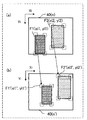
- FIG. 5 is an example of an image 40E including a marker 4b having a surface parallel to the optical axis of the photographing apparatus 11 of FIG. 1, and shows a case where the difference in height and width of the marker 4b in the image 40E is one pixel. Is. It is a figure which shows the example of the image 40F including the marker 4a which has the plane perpendicular to the optical axis of the photographing apparatus 11 of FIG. FIG.
- FIG. 5 is an example of an image 40G including a marker 4b having a surface parallel to the optical axis of the photographing apparatus 11 of FIG. 1, and shows a case where the difference in height and width of the marker 4b in the image 40G is 4 pixels.
- Is. It is a figure which shows the example of the image 40H including the marker 4a which has the plane perpendicular to the optical axis of the photographing apparatus 11 of FIG.
- FIG. 12 It is a figure which shows the 3rd example of the image displayed on the display device 14 or 25 of FIG. It is a block diagram which shows the structure of the positioning apparatus 12A which concerns on 2nd Embodiment. It is a block diagram which shows the structure of the positioning apparatus 12B which concerns on 3rd Embodiment.
- FIG. 1 is a schematic view showing the configuration of the vehicle 1 according to the first embodiment.
- the vehicle 1 may be, for example, a forklift. Further, the vehicle 1 includes a loading platform 1a on which the luggage 3 is mounted. The vehicle 1 may further include an elevating mechanism 1b for loading and unloading the luggage 3 on the loading platform 1a. Further, the vehicle 1 includes a console 1c that receives user operations such as forward movement, reverse movement, steering, and stop. Further, on the vehicle body of the vehicle 1, a photographing device 11 is installed so as to photograph a predetermined direction (front, rear, side, upward, and / or downward) with respect to the vehicle 1.
- FIG. 2 is a block diagram showing a configuration of a positioning system including the vehicle 1 of FIG.
- the positioning system of FIG. 2 includes at least one vehicle 1 and a server device 2.
- Each vehicle 1 includes a positioning device 12 that measures its position based on an image taken by the photographing device 11.
- the server device 2 acquires their positions from each vehicle 1 and records the position of each vehicle 1.
- the vehicle 1 further includes a photographing device 11, a positioning device 12, a communication device 13, a display device 14, and a drive mechanism 15.
- the photographing device 11 generates an image of the subject in a predetermined direction with respect to the vehicle 1 at predetermined time intervals while the vehicle 1 is moving.
- the photographing device 11 includes, for example, at least one camera.
- the photographing device 11 may capture a still image at predetermined time intervals, or may extract frames from a series of frames of a moving image at predetermined time intervals.
- the photographing device 11 sends the captured image to the positioning device 12.
- the photographing device 11 gives each image a time stamp of the time when the image was photographed.
- the positioning device 12 calculates the position and posture of the vehicle 1 based on the image taken by the photographing device 11.
- the positioning device 12 extracts feature points from a plurality of images captured by the photographing device 11, associates the extracted feature points between the images, and determines a predetermined reference based on the amount of change in the feature points between the images.
- the relative position and relative posture of the vehicle 1 with respect to the position and the reference posture are calculated.
- the positioning device 12 extracts one of a plurality of visually identifiable markers arranged at a predetermined position from the image captured by the photographing device 11, and one extracted marker. Based on, the absolute position and absolute posture of the vehicle 1 on the map given in advance are calculated.
- the positioning device 12 further corrects the relative position and the relative posture based on the absolute position and the absolute posture.
- the "posture" of the vehicle 1 indicates, for example, the angle of the vehicle 1 in the traveling direction with respect to the coordinate axes of a predetermined coordinate system ("world coordinate system” or “marker coordinate system” described later).
- the communication device 13 includes a module such as Wi-Fi or Bluetooth and a control program thereof, and wirelessly communicates with the server device 2.
- the communication device 13 transmits the position and posture of the vehicle 1 calculated by the positioning device 12 to the server device 2.
- the display device 14 displays an image showing the position and posture of the vehicle 1.
- the display device 14 may superimpose the position of the vehicle 1 on the map and display it. Further, the display device 14 may display an image captured by the photographing device 11. Further, the display device 14 may display information (for example, an alarm) regarding the operation of the vehicle 1.
- the drive mechanism 15 includes the engine or motor of the vehicle 1, a steering device, a braking device, a control device thereof, and the like.
- the drive mechanism 15 is controlled by the user via, for example, the console 1c.
- the server device 2 of FIG. 2 includes a processing device 21, a communication device 22, an input device 23, a storage device 24, and a display device 25.
- the processing device 21 is a general-purpose computer including, for example, a processor and a memory.
- the communication device 22 is communicably connected to the communication device 13 of the vehicle 1.
- the input device 23 includes a keyboard, a pointing device, and the like.
- the storage device 24 records the position and posture of the vehicle 1 received from the vehicle 1.
- the display device 25 displays the position and posture of the vehicle 1 received from the vehicle 1.
- the processing device 21 acquires their positions and postures from each vehicle 1 via the communication device 22, records the position and posture of each vehicle 1 in the storage device 24, and displays the position and posture of each vehicle 1. Displayed on the device 25.
- the display device 25 displays the position and posture of the vehicle 1 calculated by the positioning device 12 of the vehicle 1.
- the processing device 21 acquires a map of the movement range (warehouse, factory, etc.) of the vehicle 1 in advance, superimposes the position and posture of the vehicle 1 calculated by the positioning device 12 on this map, and displays it on the display device 25. You may. Instead, the processing device 21 may generate a map by the processing device 21 itself based on the movement route of the vehicle 1 and display this map on the display device 25. Further, the display device 25 may display an image taken by the photographing device 11 of the vehicle 1.
- the display device 14 is also referred to as a "first display device”
- the display device 25 is also referred to as a "second display device”.
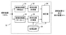
- FIG. 3 is a block diagram showing the configuration of the positioning device 12 of FIG.
- the positioning device 12 includes an image processor 31, a relative position calculator 32, an image recognizer 33, an absolute position calculator 34, a storage device 35, and a corrector 36.
- the storage device 35 includes information on identifiers, positions, and postures of a plurality of visually identifiable markers 4 arranged at predetermined positions, and a map including a passage for the vehicle 1 (for example, FIG. 4).
- the information of the warehouse 100) described with reference to the information is stored.
- the position of the marker 4 may be represented as a relative position with respect to a predetermined reference position and / or may be represented in association with a map.
- FIG. 4 is a map of the warehouse 100 including the passage 101 in which the vehicle 1 of FIG. 1 moves.
- the warehouse 100 includes structures such as a plurality of aisles 101 and a plurality of shelves 102.
- a plurality of markers 4 are arranged in advance at a plurality of predetermined positions in the warehouse 100.
- the vehicle 1 of FIG. 1 moves through the aisle 101 and conveys the luggage 3 from one shelf 102 to another shelf 102.
- the positions of the vehicle 1 and each marker 4 are represented by a world coordinate system (Xw, Yw, Zw) determined for the entire warehouse 100.
- FIG. 5A and 5B are views showing an example of the marker 4 of FIG. 4, where FIG. 5A shows a front view of the marker 4 and FIG. 5B shows a top view of the marker 4.
- the marker 4 is formed as a square flat plate.
- the marker 4 has, on one surface, a visually identifiable pattern in which the identifier of the marker 4 itself is encoded.
- the marker 4 has a pattern consisting of 7 ⁇ 7 white or black square cells in the vertical and horizontal directions.
- the pattern of the marker 4 is further formed so that the posture of the marker 4 itself can be detected from the image obtained by taking the marker 4, such as a marker used in the field of augmented reality (also referred to as “AR marker”).
- AR marker also referred to as “AR marker”.
- Each marker 4 has a marker coordinate system (Xm, Ym, Zm) whose origin is an arbitrary point (for example, a center or one vertex).
- Xm, Ym, Zm a marker coordinate system
- an arrow at the center of the plane along the Xm-Ym plane indicates the front surface of the marker 4 (positive orientation on the Zm axis).
- FIG. 6 is a table showing an example of marker information stored in the storage device 35 of FIG. In the example of FIG. 6, the information of the two markers 4 shown in FIG. 4 is shown.
- Each marker 4 has identifiers 001 and 002. This identifier is encoded in the pattern of marker 4.
- each marker 4 has predetermined coordinates in the world coordinate system (Xw, Yw, Zw). Further, each marker 4 is arranged in such a posture that its front surface (positive direction of the Zm axis) has an angle ⁇ (that is, an azimuth angle) with respect to the Xw axis in the Xw-Yw plane. The posture of each marker 4 may be represented by an azimuth angle and an elevation angle.
- each marker 4 has a square-shaped pattern and has an actual size of 30 cm ⁇ 30 cm. The size of the marker 4 indicates the size of the area of the pattern and does not include a margin around the pattern (not shown in FIG. 5).
- the storage device 35 stores marker information including items as shown in, for example, FIG. 6 for all markers 4.
- the storage device 35 stores map information including the orientation, dimensions, and arrangement of all the passages 101.
- FIG. 7 is a diagram showing an example of an image 40 captured by the photographing device 11 of FIG.
- the image 40 includes a plurality of feature points 41.
- the feature point 41 is a point where the brightness value or the color can be distinguished from the surrounding pixels and the position thereof can be accurately determined.
- the feature point 41 is detected from the pattern of the apex or edge, floor, wall, or ceiling of a structure such as a passage 101 or a shelf 102 to which the vehicle 1 moves. Further, when the vehicle 1 passes in the vicinity of the marker 4, the image 40 includes the marker 4.
- the positions of the feature points 41 and the markers 4 in the image 40 are represented by, for example, an image coordinate system (Xi, Yi) whose origin is an arbitrary point (for example, the upper left corner) of the image 40.
- the image processor 31 extracts the coordinates of the corresponding feature points from the plurality of images taken by the photographing device 11 at a plurality of times separated by a predetermined time.
- the relative position calculator 32 calculates the movement amount of the vehicle 1 based on the movement amount of the feature points in the two images that are adjacent in time.
- the relative position calculator 32 is relative to the vehicle 1 with respect to a predetermined reference position and reference posture (for example, the position and posture when the vehicle 1 starts moving) based on the coordinates of the feature points of the plurality of images. Calculate position and relative posture.
- the relative position calculator 32 may calculate the relative position and the relative posture of the vehicle 1 by using a known image processing and positioning technique such as Visual-SLAM or Visual-Odometry.
- the reference position and the reference posture are associated with the map information stored in the storage device 35. Further, the relative position calculator 32 adds a time stamp of an image (the latter of two temporally adjacent images) associated with the calculation to the relative position and the relative posture.
- the relative position calculator 32 may represent the calculated position of the vehicle 1 in, for example, Cartesian coordinates (XYZ coordinates).
- the relative position calculator 32 may calculate the speed and / or acceleration of the vehicle 1 based on the calculated position and time of the vehicle 1.
- the relative position calculator 32 calculates the calculated posture of the vehicle 1 around the roll (tilt left and right), pitch (tilt back and forth), and yaw (axis perpendicular to the floor surface (ie, Zw axis in FIG. 4)). It may be expressed by rotation). Thereby, not only the direction of the vehicle 1 in the horizontal plane parallel to the ground but also the inclination of the vehicle body of the vehicle 1 and the movement of the vehicle 1 in the height direction can be represented.
- the image processor 31 and the relative position calculator 32 are collectively referred to as a "first computer”. Further, in the present specification, the relative position and the relative posture are also referred to as “first position” and “first posture”.
- the image recognizer 33 extracts one of a plurality of visually identifiable markers 4 arranged at predetermined positions from the image taken by the photographing device 11.
- the absolute position calculator 34 refers to the information of the marker 4 and the information of the map stored in the storage device 35 based on the position and orientation of one extracted marker 4, so that the map (that is, the world coordinate system)
- the absolute position and absolute posture of the vehicle 1 indicating the position and posture of the vehicle 1 in the above are calculated.
- the absolute position calculator 34 adds time stamps of images associated with the calculations to the absolute positions and absolute postures.
- the image recognizer 33 and the absolute position calculator 34 are collectively referred to as a "second computer”. Further, in the present specification, the absolute position and the absolute posture are also referred to as “second position” and "second posture”.
- the corrector 36 corrects the relative position and the relative posture based on the absolute position and the absolute posture, and calculates the corrected position and the corrected posture of the vehicle 1.
- the corrector 36 synchronizes the absolute position and the absolute posture with the relative position and the relative posture based on the time stamp of the relative position and the relative posture and the time stamp of the absolute position and the absolute posture.
- the corrector 36 for example, considers the relative position and relative posture and the absolute position and absolute posture having a time difference smaller than a predetermined threshold value and having the closest time stamps to be calculated from the same image. May be good.
- each component 31 to 36 of the positioning device 12 may be integrated.
- the image processor 31 and the image recognizer 33 may be integrated.
- each component 31 to 36 of the positioning device 12 may be implemented as a dedicated circuit or as a program executed by a general-purpose processor.
- the corrector 36 corrects the relative position and relative posture calculated based on the feature point 41 using Visual-SLAM or the like based on the absolute position and absolute posture calculated based on the marker 4. do.
- This correction process is based on the premise that the absolute position and the absolute posture of the vehicle 1 are correct, and therefore, it is premised that the posture of the marker 4 is correctly recognized from the image taken by the marker 4. However, an object that is not the marker 4 may be erroneously detected as the marker 4. Further, in order to correctly recognize the posture of the marker 4, it is necessary to photograph the marker 4 from an appropriate angle and an appropriate distance.
- the absolute position calculator 34 captures the marker 4 from an appropriate angle and an appropriate distance, that is, the recognized marker 4 can be trusted. Only when the marker 4 is reliable, the absolute position and the absolute posture of the vehicle 1 calculated based on the position and the posture of the marker 4 are sent to the corrector 36. As a result, the corrector 36 corrects the position and posture of the vehicle 1 based on the absolute position and the absolute posture only when the marker 4 is reliable. Thereby, the position and posture of the vehicle 1 can be correctly corrected based on the correctly recognized position and posture of the marker 4, and therefore the position and posture of the vehicle 1 can be measured with high accuracy.
- FIG. 8 is a flowchart showing a positioning process executed by the positioning device 12 of FIG.
- step S1 the positioning device 12 acquires an image captured by the photographing device 11.
- step S2 the image processor 31 and the relative position calculator 32 execute the relative position calculation process to calculate the relative position and the relative posture of the vehicle 1.
- step S3 the image recognizer 33 and the absolute position calculator 34 execute the absolute position calculation process to calculate the absolute position and the absolute posture of the vehicle 1.
- Steps S2 and S3 may be executed in parallel or sequentially as shown in FIG.
- step S4 the corrector 36 executes the correction process, corrects the relative position and the relative posture based on the absolute position and the absolute posture, and calculates the corrected position and the corrected posture of the vehicle 1.
- step S5 the corrector 36 outputs the corrected position and the corrected posture of the vehicle 1 to the communication device 13 and the display device 14.
- FIG. 9 is a flowchart showing the subroutine of step S2 (relative position calculation processing) of FIG.
- step S11 the image processor 31 acquires the first and second images (for example, temporally adjacent frames) taken at the first and second times separated by a predetermined time, respectively.
- step S12 the image processor 31 detects a feature point from the first image.
- an image processing technique such as FAST (Faires from Accelerated Segment Test) may be used.
- step S13 the image processor 31 detects the feature points corresponding to the feature points of the first image from the second image.
- a known image processing technique such as a KLT (Kanade-Lucas-Tomasi) tracker, may be used to detect the corresponding feature points between the images.
- FIG. 10 is a diagram showing feature points extracted by the image processor 31 of FIG. FIG. 10A shows feature points F1 and F2 extracted from the image 40 (n) at time n.
- FIG. 10B shows feature points F1'and F2' extracted from the image 40 (n') at time n'.
- the feature point F1 has the coordinates (xi1, ii1)
- the feature point F2 has the coordinates (xi2, ii2).
- the feature point F1' has coordinates (xi1', yi1')
- the feature point F2' has coordinates (xi2', yi2').
- the feature points F1'and F2'in FIG. 10B correspond to the feature points F1 and F2 in FIG. 10A, respectively.
- the image processor 31 acquires a set of coordinates of the corresponding feature points in the first and second images.
- the image processor 31 acquires, for example, a set of coordinates of feature points F1, F1'(xi1, ii1, xi1', yi1'), and a set of coordinates of feature points F2, F2'(xi2, ii2, xi2'). , Yi2').
- step S15 the relative position calculator 32 calculates a basic matrix E composed of 3 ⁇ 3 elements based on the coordinates of the feature points acquired in step S14, for example, using a 5-point algorithm.
- step S16 the relative position calculator 32 performs a singular value decomposition on the basic matrix E to represent a rotation matrix R and translation representing the movement of the vehicle 1 between the times when the first and second images were taken. Calculate the vector t.
- the rotation matrix R shows the change in the posture of the vehicle 1 between the times when the first and second images are taken.
- the translation vector t indicates the change in the position of the vehicle 1 between the times when the first and second images are taken.
- the matrix T VW ⁇ V T consisting of 3 ⁇ 3 pieces of elements are calculated.
- step S17 the relative position calculator 32 calculates the relative position and the relative posture of the vehicle 1.
- the relative position t (n) of the vehicle 1 at the current time n is set to step S16.
- the relative position calculator 32 cumulatively adds the plurality of translation vectors and cumulatively multiplies the plurality of rotation matrices, thereby causing the vehicle 1 to be relative to the predetermined reference position and reference posture. Calculate the posture.
- the relative position calculator 32 sends the calculated relative position and relative posture of the vehicle 1 to the corrector.
- FIG. 11 is a flowchart showing the subroutine of step S3 (absolute position calculation process) of FIG.
- the image recognizer 33 detects the marker 4 from the image.
- the image recognizer 33 detects the coordinates of the four vertices (corners) of the quadrangular marker 4 in the image coordinate system, and decodes the pattern of the marker 4 to acquire the identifier of the marker 4.
- the image recognizer 33 may detect the coordinates of some predetermined points instead of the four vertices of the marker 4.
- FIG. 12 is a diagram showing the coordinates of the vertices of the marker 4 in the marker coordinate system.
- the four vertices of the marker 4 are the coordinates (xm0, ym0, zm0), (xm1, ym1, zm1), (xm2, ym2, zm2), and (xm3, ym3). , Zm3) respectively. Since the dimensions of the marker 4 are known, the coordinates of the four vertices of the marker 4 in the marker coordinate system are also known. For example, when the upper left vertex of the marker 4 in FIG.
- FIG. 13 is a diagram showing the coordinates of the vertices of the marker 4 in the image 40A photographed by the photographing apparatus 11 of FIG.
- the four vertices of the marker 4 have coordinates (xi0, yi0), (xi1, yi1), (xi2, yi2), and (xi3, yi3), respectively.
- the absolute position calculator 34 determines the position of the marker 4 and the position of the marker 4 in the three-dimensional coordinate system (camera coordinate system) with the photographing device 11 as the origin, based on the coordinates of the marker 4 detected in step S21.
- the posture that is, the position and posture of the marker 4 as seen from the photographing device 11
- the absolute position calculator 34 is PnP (perspective n) based on the coordinates of the four vertices of the marker 4 in the two-dimensional image coordinate system and the coordinates of the four vertices of the marker 4 in the three-dimensional marker coordinate system. point)
- the absolute position calculator 34 calculates the position and orientation of the photographing device 11 in the marker coordinate system (that is, the position and orientation of the photographing device 11 as seen from the marker 4).
- the position of the marker 4 as seen from the photographing device 11 is indicated by the translation vector t
- the posture of the marker 4 as seen from the photographing device 11 is indicated by the rotation matrix R.
- the posture of the photographing device 11 as seen from the marker 4 is represented by R -1
- the position of the photographing device 11 as seen from the marker 4 is represented by ⁇ R -1 t.
- step S24 the absolute position calculator 34 executes the marker evaluation process (described later with reference to FIGS. 17 to 46), and whether or not the marker 4 is photographed from an appropriate angle and an appropriate distance, that is, , Judge whether the recognized marker 4 can be trusted.
- the process proceeds from step S25 to step S26, and when not, the process proceeds to step S4 in FIG.
- step S26 the absolute position calculator 34 receives from the storage device 35 the position and orientation of the marker 4 in the world coordinate system (ie, the absolute position and absolute position of the marker 4) based on the identifier of the marker 4 detected in step S21. Posture) is read.
- step S27 the absolute position calculator 34 is based on the position and orientation of the photographing device 11 in the marker coordinate system calculated in step S23 and the position and orientation of the marker 4 in the world coordinate system read out in step S26. Then, the position and attitude of the vehicle 1 in the world coordinate system (that is, the absolute position and the absolute attitude of the vehicle 1) are calculated. By adding the position and orientation of the marker 4 in the world coordinate system as an offset value to the position and orientation of the photographing device 11 in the marker coordinate system, the position and orientation of the vehicle 1 in the world coordinate system can be obtained.
- the absolute position calculator 34 sends the calculated absolute position and absolute posture of the vehicle 1 to the corrector 36.
- FIG. 14 is a flowchart showing the subroutine of step S4 (correction processing) of FIG.
- the corrector 36 When performing the correction process of FIG. 14, the corrector 36 internally holds the latest absolute position and absolute posture calculated previously in the initial state.
- step S31 the corrector 36 calculates the corrected movement amount of the vehicle 1 based on the relative position and the absolute position of the vehicle 1.
- FIG. 15 is a diagram for explaining the correction movement amount calculated in step S31 of FIG. FIG. 15 shows the position of the vehicle 1 calculated by the positioning device 12.
- vehicle 1 has relative positions P (n-2) to P (n + 2).
- the positioning device 12 detects the marker 4.
- the positioning device 12 calculates the difference between the relative position P (n) and the position of the marker 4 as the corrected movement amount ⁇ .
- the positioning device 12 adds the corrected movement amount ⁇ to the relative position P (n) to obtain the corrected position P'(n).
- the positioning device 12 adds the correction movement amount ⁇ to the relative positions P (n + 1), P (n + 2), ..., And the corrected positions P'(n + 1), P'(n + 2), ... To get.
- step S32 of FIG. 14 the corrector 36 adds the corrected movement amount of the vehicle 1 to the relative position of the vehicle 1.
- step S33 the corrector 36 calculates the corrected rotation amount of the vehicle 1 based on the relative posture and the absolute posture of the vehicle 1.
- FIG. 16 is a diagram for explaining the correction rotation amount calculated in step S33 of FIG.
- FIG. 16 shows the positions P, P'and the postures A, A'of the vehicle 1 calculated by the positioning device 12.
- vehicle 1 has relative positions P (n-2) to P (n + 2) and relative postures A (n-2) to A (n + 2).
- the thick arrow indicates the posture of the vehicle 1.
- the positioning device 12 detects the marker 4 and calculates the absolute posture of the vehicle 1.
- the positioning device 12 calculates the difference between the relative posture A (n) and the absolute posture as the corrected rotation amount ⁇ , with the relative position P (n) as the center of rotation.
- the positioning device 12 adds the corrected rotation amount ⁇ to the relative posture A (n) to obtain the corrected posture A'(n). After that, similarly, the positioning device 12 adds the correction rotation amount ⁇ to the relative postures A (n + 1), A (n + 2), ..., And the corrected postures A'(n + 1), A'(n + 2), ... To get.
- step S33 the corrector 36 determines the difference between the absolute posture and the average value of the plurality of relative postures calculated (or corresponding to a predetermined number of consecutive images) over a predetermined time length. , It may be calculated as the corrected rotation amount of the vehicle 1. It is not possible to determine the actual traveling direction of the vehicle 1 (for example, whether or not the vehicle 1 is moving along the passage 101) only from the instantaneous value of the relative posture of the vehicle 1. Further, the relative posture of the vehicle 1 may include an error. Therefore, by using the average value of the plurality of relative postures, the actual traveling direction of the vehicle 1 can be accurately determined.
- step S34 of FIG. 14 the corrector 36 adds the corrected rotation amount of the vehicle 1 to the relative posture of the vehicle 1.
- FIG. 17 is a flowchart showing a subroutine of step S24 (marker evaluation process) of FIG.
- step S41 of FIG. 17 the absolute position calculator 34 determines whether or not the surface of the marker 4 appears perpendicular to the optical axis of the photographing device 11 in the image captured by the photographing device 11, and YES. When, the process proceeds to step S48, and when NO, the process proceeds to step S42.
- the markers 4 may be difficult to distinguish the markers 4 having surfaces at different angles with respect to the optical axis of the photographing device 11. For example, at the end of the image captured by the photographing device 11, it becomes difficult to distinguish between the marker 4 having a surface perpendicular to the optical axis of the photographing device 11 and the marker 4 having a surface parallel to the optical axis.
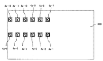
- FIG. 18 is a diagram showing an exemplary arrangement of markers 4a-1 to 4a-12 photographed by the photographing apparatus 11 of FIG.
- Each marker 4a-1 to 4a-12 has a square-shaped pattern and an actual size (not including the margin around the pattern) of 0.6 m ⁇ 0.6 m.
- the faces of the markers 4a-1 to 4a-12 are arranged perpendicular to the optical axis of the photographing apparatus 11, that is, parallel to the Xw-Zw plane.
- FIG. 19 is a diagram showing an example of an image 40B in which the markers 4a-1 to 4a-12 of FIG. 18 are photographed by the photographing apparatus 11.
- FIG. 20 is a diagram showing an exemplary arrangement of markers 4b-1 to 4b-12 photographed by the photographing apparatus 11 of FIG.
- Each marker 4b-1 to 4b-12 has a square-shaped pattern and an actual size (not including the margin around the pattern) of 0.6 m ⁇ 0.6 m. Further, the markers 4b-1 to 4b-12 are arranged so that their surfaces are parallel to the optical axis of the photographing apparatus 11, that is, parallel to the Yw-Zw plane.
- FIG. 21 is a diagram showing an example of an image 40C in which the markers 4b-1 to 4b-12 of FIG. 20 are photographed by the photographing apparatus 11. Comparing FIG. 21 with FIG. 19, markers 4b-6 in FIG. 21 are almost the same as markers 4a-1 to 4a-12 in FIG. 19 in image 40C, although the orientations of the surfaces are different by 90 degrees. It can be seen that it looks like size and shape.
- FIG. 22 is a diagram illustrating changes in the position of the photographing device 11 in the marker coordinate system due to erroneous detection of the angle of the surface of the marker 4 with respect to the optical axis of the photographing device 11 of FIG.
- the markers 4a-1 to 4a-12 in FIG. 19 and the markers 4b-6 in FIG. 21 are apparently indistinguishable from each other. Therefore, in the marker coordinate system of FIG. 22, the photographing apparatus 11 may be erroneously determined to have the position and orientation of "11b" where it should have the position and orientation of "11a", and vice versa. In some cases. As will be described later with reference to FIGS.
- the absolute position calculator 34 does not use the marker 4, which appears to have a plane perpendicular to the optical axis of the photographing device 11, in calculating the absolute position and absolute posture of the vehicle 1. Treat as a thing.
- the marker 4 that appears to have a plane perpendicular to the optical axis of the photographing device 11 is a marker 4 that actually has a plane perpendicular to the optical axis of the photographing device 11 (marker 4-1 in FIG. 18). -4a-12) and a marker 4 (marker 4b-6 in FIG. 20) that is apparently indistinguishable from those having a plane perpendicular to the optical axis of the photographing apparatus 11.
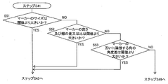
- FIG. 23 is a flowchart showing the subroutine in step S41 of FIG. Step S41 may include, for example, the following steps.
- step S51 the absolute position calculator 34 determines whether or not the apparent size of the marker 4 in the image captured by the photographing device 11 is larger than the threshold value. If YES, the process proceeds to step S42 of FIG. In the case of, the process proceeds to step S52.
- the apparent size of the marker 4 in the image is, for example, the apparent height and width of the marker 4 in the image, and is represented by, for example, the number of pixels.
- the threshold value in step S51 is, for example, 30 pixels.
- the marker 4, which occupies a small area in the image may be erroneously recognized. On the other hand, the marker 4, which occupies a large area in the image, is considered to be difficult to be erroneously recognized.
- step S52 the absolute position calculator 34 determines whether or not the difference or ratio of the apparent height and width of the marker 4 in the image captured by the photographing device 11 is larger than the threshold value, and if YES, FIG. 17 Step S42, and if NO, the process proceeds to step S53.
- the apparent height and width of the marker 4 in the image is represented by, for example, the number of pixels.
- the threshold value is, for example, 3 pixels.
- a marker 4 having an apparent height and width of approximately the same length in an image may appear to have a plane perpendicular to the optical axis of the imaging device 11.
- the marker 4 having substantially different lengths of apparent height and width in the image has a surface inclined with respect to the optical axis of the photographing apparatus 11.
- step S53 the absolute position calculator 34 determines whether or not the apparent angle difference between the adjacent corners of the markers 4 in the image captured by the photographing device 11 is larger than the threshold value, and if YES, FIG. 17 shows. The process proceeds to step S42, and if NO, the process proceeds to step S48 in FIG.
- the threshold value in step S53 is, for example, 30 degrees. Markers 4 having substantially equal angles of adjacent angles in an image may appear to have a plane perpendicular to the optical axis of the photographing apparatus 11. On the other hand, it is considered that the markers 4 having substantially different angles adjacent to each other in the image have a surface inclined with respect to the optical axis of the photographing apparatus 11.
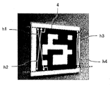
- FIG. 24 is a diagram illustrating the apparent height of the marker 4 in the image according to steps S51 and S52 of FIG. 23.
- FIG. 25 is a diagram illustrating the apparent width of the marker 4 in the image according to steps S51 and S52 of FIG. 23.
- the pattern of the marker 4 has a quadrangular shape.
- the apparent height of the marker 4 in the image is represented by the length of the shortest perpendicular line among the perpendicular lines h1 to h4 from the four vertices to the opposite side, referring to FIG. 24.
- the apparent width of the marker 4 in the image is represented by the length of the shortest perpendicular line among the perpendicular lines w1 to w4 from the four vertices to the opposite side, referring to FIG. 25.
- the apparent height and width of the marker 4 in the image indicates the apparent height and width of the pattern in the image, and does not include a margin around the pattern.
- FIG. 26 is a diagram for explaining the apparent angle difference between the angles of the markers 4 adjacent to each other in the image according to step S53 of FIG. 23.
- the apparent angle difference between the adjacent corners of the markers 4 in the image indicates the apparent angle difference between the adjacent corners of the pattern in the image, and does not include the margin around the pattern.
- the apparent angle of the upper left corner of the marker 4 is 80 degrees
- the apparent angle of the upper right corner of the marker 4 is 100 degrees. Therefore, the apparent angle difference between the upper left corner and the upper right corner of the marker 4 in the image is 20 degrees.
- FIG. 27 is a diagram showing an example of an image 40D including a marker 4a having a plane perpendicular to the optical axis of the photographing apparatus 11 of FIG.
- FIG. 28 is an example of the image 40E including the marker 4b having a surface parallel to the optical axis of the photographing apparatus 11 of FIG. 1, and the difference in height and width of the marker 4b in the image 40E is one pixel. It is a figure which shows the case. Comparing FIGS. 27 and 28, when the difference in height and width of the marker 4b in the image is smaller than the threshold value of 3 pixels, the marker 4b having a plane perpendicular to the optical axis of the photographing apparatus 11 (FIG. 28). ) Is difficult to distinguish from the marker 4a (FIG. 27) having parallel surfaces.
- FIG. 29 is a diagram showing an example of an image 40F including a marker 4a having a plane perpendicular to the optical axis of the photographing apparatus 11 of FIG.
- FIG. 30 is an example of the image 40G including the marker 4b having a surface parallel to the optical axis of the photographing apparatus 11 of FIG. 1, and the difference in height and width of the marker 4b in the image 40G is 4 pixels. It is a figure which shows the case. Comparing FIGS. 29 and 30, when the difference in height and width of the marker 4b in the image is larger than the threshold value of 3 pixels, the marker 4b having a plane perpendicular to the optical axis of the photographing device 11 (FIG. 30). ) Is distinguishable from the marker 4a (FIG. 29) having parallel planes.
- FIG. 31 is a diagram showing an example of an image 40H including a marker 4a having a plane perpendicular to the optical axis of the photographing apparatus 11 of FIG.
- FIG. 32 is an example of the image 40I including the marker 4b having a plane parallel to the optical axis of the photographing apparatus 11 of FIG. 1, and the angle difference between the angles of the markers 4b adjacent to each other in the image 40I is 35 degrees. It is a figure which shows a certain case. Comparing FIGS. 31 and 32, when the angle difference between the angles of the markers 4b adjacent to each other in the image is larger than the threshold value of 30 degrees, the marker 4b having a plane perpendicular to the optical axis of the photographing apparatus 11 (FIG. 31). 32) is distinguishable from the marker 4a (FIG. 31) having parallel planes.
- step S41 of FIG. 17 it is not suitable for calculating the absolute position and absolute posture of the marker 4, that is, the vehicle 1, which is apparently difficult to distinguish even though it has surfaces at different angles with respect to the optical axis of the photographing device 11. Marker 4 can be detected and removed.
- step S42 of FIG. 17 the absolute position calculator 34 counts the number of images that are continuously captured by the photographing device 11 and in which the markers 4 having the same identifier are extracted. Further, in step S42, in the absolute position calculator 34, does the absolute position calculator 34 have the same identifier in the predetermined number of markers 4 extracted from the predetermined number of images continuously photographed by the photographing device 11. Whether or not it is determined, and if YES, the process proceeds to step S43, and if NO, the process proceeds to step S48.
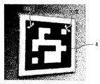
- FIG. 33 is a diagram showing an example of the image 40J photographed by the photographing apparatus 11 of FIG.
- some object 5 is used as a marker, i.e., a visually identifiable area having a marker identifier (eg, ID: 668).
- a marker identifier eg, ID: 668.
- the pattern of the marker 4 is simple, it is easy to erroneously recognize another object 5 as a marker.
- FIG. 34 is a table including the marker 4 detected by the image recognizer 33 of FIG. 3 and the object erroneously detected as the marker 4.
- Each row of the table in FIG. 34 shows a candidate for marker 4 (marker 4 or erroneously detected object) extracted from each image captured by the photographing apparatus 11. Candidates for one or more markers 4 may be detected from one image, and candidates for markers 4 may not be detected from an image.
- the identifier (ID) first column
- the time when the image including the candidate of the marker 4 was taken second column
- the position third to fifth column
- the position third to fifth column
- the angle (6th column is the angle (6th column).
- the image recognizer 33 When the image recognizer 33 is detecting the marker 4, there is a possibility that the object 5 in the vicinity of the marker 4 is temporarily erroneously recognized as a marker. However, even if the object 5 is erroneously detected as the marker 4 in a certain image, it is highly unlikely that the object 5 is erroneously detected as the marker 4 over a plurality of consecutive images. Therefore, even if an object 5 having a certain identifier (for example, ID: 668) is detected in a certain image, if it is not detected in a plurality of consecutive images, it can be determined that the object 5 is not the marker 4. On the other hand, when the marker 4 having the same identifier (for example, ID: 010) is detected in a plurality of images continuously captured by the photographing device 11, it can be determined that the marker 4 is detected.
- ID: 010 when the marker 4 having the same identifier (for example, ID: 010) is detected in a plurality of images continuously captured by the photographing device 11,
- the threshold value (predetermined number) of step S42 in FIG. 17 is set to, for example, "3", but may be set to any other value.
- Step S43 In step S43 of FIG. 17, the absolute position calculator 34 is determined in advance with markers 4 having the same identifier extracted from a predetermined number of images continuously photographed by the photographing apparatus 11 as origins. The position and orientation of the photographing device 11 (that is, the vehicle 1) are calculated in the specified number of marker coordinate systems. Further, in step S43, the absolute position calculator 34 determines whether or not the coordinates of the photographing device 11 (that is, the vehicle 1) in the marker coordinate system have the same code continuously over a predetermined number (threshold value) of images. If YES, the process proceeds to step S44, and if NO, the process proceeds to step S48.
- FIG. 35 is a diagram showing an example of an image 40K taken by the photographing device 11 of FIG. 1 and including a marker 4 suitable for calculating the absolute position and absolute posture of the vehicle 1.
- FIG. 36 is a diagram showing an example of an image 40L taken by the photographing device 11 of FIG. 1 and including a marker 4 which is not suitable for calculating the absolute position and the absolute posture of the vehicle 1.
- an image for example, when the opposite sides of a rectangular marker 4 have different lengths, it is necessary to clearly determine where the photographing device 11 is photographing the marker 4, that is, the position of the photographing device 11 in the marker coordinate system. Can be done. For example, as shown in FIG.
- FIG. 37 shows the reversal of the position of the photographing device 11 in the marker coordinate system when the optical axis of the photographing device 11 of FIG. 1 substantially passes through the center of the surface of the marker 4 and is substantially orthogonal to the surface of the marker 4. It is a figure explaining.
- the Xm coordinate of the photographing device 11c located on the right side with respect to the normal of the marker 4 is positive, and the Xm coordinate of the photographing device 11d located on the left side with respect to the normal of the marker 4 is negative. be.
- FIG. 38 is a table showing changes in the position of the photographing apparatus 11 in the marker coordinate system calculated by the position calculator 34 of FIG.
- Each row of the table in FIG. 38 corresponds to each image captured by the photographing device 11, and the identifier of one marker 4 included in each image and the photographing device 11 in the marker coordinate system with the marker 4 as the origin. Indicates the position and posture of.
- the code of the coordinates of the photographing device 11 in the marker coordinate system is likely to fluctuate. ..
- the image including the marker 4 is not suitable for the calculation of the absolute position and the absolute posture of the vehicle 1.
- the coordinates of the photographing device 11 in the marker coordinate system have the same reference numerals over a predetermined number of images, the image including the marker 4 is suitable for calculating the absolute position and absolute posture of the vehicle 1. It can be judged that there is.
- the corresponding image is not suitable for calculating the absolute position and absolute posture of the vehicle 1.
- the Xm, Ym, and Zm coordinates have the same sign, so that the corresponding image is suitable for calculating the absolute position and absolute posture of the vehicle 1.
- the threshold value (predetermined number) in step S43 in FIG. 17 is set to, for example, "3", but may be set to any other value.
- step S44 of FIG. 17 the absolute position calculator 34 calculates the apparent size of the marker 4 in the image captured by the imaging device 11. Further, in step S44, the absolute position calculator 34 determines whether or not the apparent size of the marker 4 in the image is larger than a predetermined threshold value, and if YES, proceeds to step S45, and if NO, step. Proceed to S48.
- FIG. 39 is a diagram showing an example of an image of a marker 4 taken by the photographing device 11 of FIG. 1 and having a width suitable for calculating the absolute position and absolute posture of the vehicle 1.
- FIG. 40 is a diagram showing an example of an image of a marker 4 which is photographed by the photographing apparatus 11 of FIG. 1 and does not have a width suitable for calculating the absolute position and the absolute posture of the vehicle 1.
- 39 and 40 show the apparent size (number of pixels) of the marker 4 in the image captured by the photographing apparatus 11.
- the apparent size of the marker 4 in the image is represented by the number of pixels from each vertex to the opposite side thereof.
- the marker 4 In order to correctly recognize the pattern of the marker 4, the marker 4 needs to have a sufficiently large apparent size (number of pixels) in the image captured by the photographing device 11.
- the marker 4 shown in FIG. 5 has a pattern consisting of 7 ⁇ 7 white or black square cells in the vertical and horizontal directions.
- the number of pixels of the marker 4 in FIG. 39 is sufficient to recognize each cell of the pattern.
- the number of pixels of the marker 4 in FIG. 40 is clearly insufficient to recognize each cell of the pattern.
- FIG. 41 is a graph showing an error in the absolute position of the vehicle 1 when the threshold value in step S44 of FIG. 17 is changed. According to FIG. 41, it can be seen that the error becomes smaller when the threshold value is set to 14 or more. Therefore, when the apparent size of the marker 4 in the image captured by the photographing device 11 is smaller than a predetermined threshold value, it is determined that the image including the marker 4 is not suitable for calculating the absolute position and absolute posture of the vehicle 1. be able to. On the other hand, when the apparent size of the marker 4 in the image is larger than a predetermined threshold value, it can be determined that the image including the marker 4 is suitable for calculating the absolute position and the absolute posture of the vehicle 1.
- the threshold value of step S44 in FIG. 17 may be set to a value different from the threshold value of step S51 of FIG. 23.
- the threshold value of step S51 in FIG. 23 is such that the marker 4 having an apparent size suitable for calculating the absolute position and absolute posture of the vehicle 1 is detected and extracted (that is, step S51 is YES). If there is), it is set to a relatively large value (30 pixels).
- the threshold value in step S44 of FIG. 17 is such that the marker 4 having an apparent size unsuitable for calculating the absolute position and absolute posture of the vehicle 1 is detected and removed (that is, when step S44 is NO). , Is set to a relatively small value (14 pixels).
- the apparent size of the marker 4 in the image is the length of each side, the total length of each side, the length of the diagonal line, or the area of the marker 4 instead of the distance (number of pixels) from each vertex to the opposite side. May be represented by.
- step S45 of FIG. 17 the absolute position calculator 34 determines the direction of the vehicle 1 with respect to the normal of the surface of the one marker 4 based on the position and orientation of the vehicle 1 in the marker coordinate system with one marker 4 as the origin. Calculate the angle to. Further, in step S45, whether the absolute position calculator 34 has an angle in the marker coordinate system in the direction of the photographing device 11 (that is, the vehicle 1) with respect to the normal of the surface of one marker 4 is larger than a predetermined threshold value ⁇ th. Whether or not it is determined, and if YES, the process proceeds to step S46, and if NO, the process proceeds to step S48.
- the absolute position calculator 34 determines whether or not the angle between the normals of the surfaces of the photographing device 11 and the marker 4 is larger than the threshold value ⁇ th, and if YES, determines whether or not the angle is larger than the threshold value ⁇ th. The process proceeds to step S46, and if NO, the process proceeds to step S48.
- FIG. 42 is a diagram illustrating an angle and a distance at which an image of the marker 4 suitable for calculating the absolute position and absolute posture of the vehicle 1 can be taken in the marker coordinate system.
- the position of the photographing apparatus 11 in the marker coordinate system can be clearly determined when, for example, the opposite sides of the rectangular markers 4 have different lengths from each other in the image. Therefore, the photographing device 11 photographs the marker 4 not from the normal direction (front) of the marker 4 but from a direction sufficiently inclined from the normal direction of the marker 4.
- FIG. 43 is a diagram for explaining the angle conditions when taking an image of the marker 4 suitable for calculating the absolute position and absolute posture of the vehicle 1.
- FIG. 44 is a diagram showing an example of an image 40M including a marker 4 photographed by the photographing apparatus 11 of FIG. 43.
- ⁇ indicates an angle in the direction of the photographing device 11 with respect to the normal of the surface of the marker 4.
- the positive or negative angle ⁇ can be determined from the orientation of the trapezoid in FIG.
- ⁇ is an angle in the direction of the marker 4 with respect to the optical axis of the photographing device 11.
- the angle ⁇ indicates the position of the marker 4 in the image 40M captured by the imaging device 11.
- the accuracy becomes higher in the order of ⁇ > d> ⁇ .
- the threshold value ⁇ th in step S45 in FIG. 17 is set to, for example, “45 degrees”, but may be set to any other value. Further, the threshold value ⁇ th may vary depending on the distance from the photographing device 11 to the marker 4.
- the apparent size a of the marker 4 in the image captured by the photographing device 11 becomes smaller, and the condition of step S44 is satisfied. Becomes difficult.
- the angle of the marker 4 with respect to the normal of the surface in the direction of the photographing device 11 must satisfy both the conditions of steps S44 and S45.
- step S46 of FIG. 17 the absolute position calculator 34 calculates the distance from the vehicle 1 to the marker 4 based on the image taken by the photographing device 11. Further, in step S46, the absolute position calculator 34 determines whether or not the distance from the photographing device 11 (that is, the vehicle 1) to the marker 4 is smaller than a predetermined threshold value, and if YES, proceeds to step S47. If NO, the process proceeds to step S48.
- the photographing device 11 photographs the marker 4 at a position shorter than the distance Dth with respect to the marker 4. If the distance from the photographing device 11 to the marker 4 is large, the accuracy of the position and posture of the vehicle 1 calculated by the positioning device 12 decreases.
- the threshold value Dth in step S46 in FIG. 17 is set to, for example, “6 m”, but may be set to any other value. Further, the threshold value Dth may vary depending on the apparent size of the marker 4 in the image.
- step S47 of FIG. 17 the absolute position calculator 34 determines that the marker 4 is reliable. In this case, the absolute position calculator 34 sends the absolute position and the absolute posture calculated based on the position and the posture of the marker 4 to the corrector 36. On the other hand, in step S48, the absolute position calculator 34 determines that the marker 4 is unreliable. In this case, the absolute position calculator 34 does not send the absolute position and the absolute posture calculated based on the position and the posture of the marker 4.
- the absolute position calculator 34 can trust whether or not the marker 4 is photographed from an appropriate angle and an appropriate distance, that is, the recognized marker 4 can be trusted. Judge whether or not.
- the corrector 36 operates as follows.
- the corrector 36 corrects the position and posture of the vehicle 1.
- the absolute position and absolute position calculated based on the position and position of the marker 4 are not used.
- the corrector 36 corrects the position and posture of the vehicle 1. Therefore, the absolute position and the absolute posture calculated based on the position and the posture of the marker 4 can be used.
- the corrector 36 determines the position of the marker 4 in order to correct the position and orientation of the vehicle 1. And do not use absolute positions and attitudes calculated based on attitudes.
- the corrector 36 is based on the position and orientation of the marker 4 in order to correct the position and orientation of the vehicle 1. Absolute position and absolute attitude calculated in the above can be used.
- step S43 When the coordinates of the vehicle 1 in each marker coordinate system do not have the same code over a number of images equal to a predetermined threshold value (step S43 is NO), the corrector 36 corrects the position and orientation of the vehicle 1. The absolute position and absolute position calculated based on the position and position of the marker 4 are not used. On the other hand, when the coordinates of the vehicle 1 in each marker coordinate system have the same code over the number of images equal to or larger than the threshold value (YES in step S43), the corrector 36 uses the marker 4 to correct the position and posture of the vehicle 1. Absolute positions and attitudes calculated based on the position and orientation of are available.
- the corrector 36 is based on the position and orientation of the marker 4 in order to correct the position and orientation of the vehicle 1. Do not use the absolute position and attitude calculated in.
- the corrector 36 is calculated based on the position and posture of the marker 4 in order to correct the position and posture of the vehicle 1. Absolute position and absolute posture can be used.
- step S45 When the angle of one marker 4 in the direction of the vehicle 1 with respect to the normal of the surface is equal to or less than a predetermined threshold value (step S45 is NO), the corrector 36 corrects the position and orientation of the vehicle 1. , Absolute position and absolute position calculated based on the position and position of marker 4 are not used. On the other hand, when the angle of one marker 4 with respect to the normal of the surface of the vehicle 1 in the direction of the vehicle 1 is larger than the threshold value (YES in step S45), the corrector 36 uses the marker 4 to correct the position and posture of the vehicle 1. Absolute positions and attitudes calculated based on the position and orientation of are available.
- the corrector 36 When the distance from the vehicle 1 to the marker 4 is equal to or greater than a predetermined threshold (NO in step S46), the corrector 36 is based on the position and orientation of the marker 4 in order to correct the position and orientation of the vehicle 1. Do not use the absolute position and attitude calculated in. On the other hand, when the distance from the vehicle 1 to the marker 4 is smaller than the threshold value (YES in step S46), the corrector 36 is calculated based on the position and posture of the marker 4 in order to correct the position and posture of the vehicle 1. Absolute position and absolute posture can be used.
- the corrector 36 calculates the absolute position and the absolute position calculated based on the position and the posture of the marker 4 in order to correct the position and the posture of the vehicle 1. Use absolute posture.
- the threshold value of step S52 in FIG. 23 is also referred to as a “first threshold value”
- the threshold value of step S53 is also referred to as a “second threshold value”
- the threshold value of step S51 is also referred to as a “third threshold value”.
- the threshold value of step S45 is also referred to as a "fourth threshold value”
- the threshold value of step S42 is also referred to as a "fifth threshold value”
- the threshold value of step S43 is also referred to as a "sixth threshold value”.
- the threshold value of S46 is also referred to as a "seventh threshold value”.
- FIG. 45 is a diagram showing a locus 103 of the vehicle 1 calculated by executing the correction process according to the comparative example of the first embodiment.
- FIG. 46 is a diagram showing a locus 104 of the vehicle 1 calculated by executing the marker evaluation process of FIG.
- the front surface of the marker 4 Zm axis in FIG. 5
- the protrusions provided on one side of each marker 4, but in reality, there is no such protrusion.
- the calculated position of the vehicle 1 at the position surrounded by the broken line is due to the failure to correctly recognize the marker 4 having a surface at a different angle with respect to the optical axis of the photographing device 11. There is an error.
- the positioning device 12 since the positioning device 12 does not use the marker 4 which appears to have a plane perpendicular to the optical axis of the photographing device 11 in the calculation of the absolute position and the absolute posture of the vehicle 1, the vehicle.
- the position and posture of 1 can be measured with high accuracy.
- FIG. 47 is a diagram showing a first example of an image displayed on the display device 14 or 25 of FIG.
- FIG. 48 is a diagram showing a second example of an image displayed on the display device 14 or 25 of FIG.
- FIG. 49 is a diagram showing a third example of an image displayed on the display device 14 or 25 of FIG.
- the display devices 14 and 25 display images showing the position and posture of the vehicle 1.
- the image showing the position and posture of the vehicle 1 may be an image in which the position and posture of the vehicle 1 are superimposed on the map, or may be an image taken by the photographing device 11.
- the images 111 to 113 displayed on the display device 14 or 25 have a window 120 including an image taken by the photographing device 11 superimposed on the map.
- FIGS. 47 and 48 show the current relative position and relative posture of the vehicle 1 calculated by the relative position calculator 32 by the position and orientation of the triangle. Further, FIGS. 47 and 48 show the loci 105 and 106 of the vehicle 1 based on the relative position and the relative posture, respectively. Here, the locus 106 is a continuation of the locus 105. In the examples of FIGS. 47 and 48, the vehicle 1 is actually traveling straight up along the passage 101 in front of the marker 4 having the identifier "003", but due to a calculation error, the vehicle 1 Is displayed as if it had rushed into the shelf 102.
- FIG. 49 shows the current position and posture of the vehicle 1 corrected based on the absolute position and absolute posture calculated based on the marker 4 having the identifier “003” by the position and orientation of the triangle. Further, FIG. 49 shows the locus 107 of the vehicle 1 including the section 107a based on the corrected position and posture. The locus 107 is also a continuation of the locus 105.
- the marker 4 having the identifier "003" is photographed as shown in the window 120 of FIG. 47.
- the absolute position calculator 34 calculates the absolute position and absolute posture of the vehicle 1 based on the marker 4 having the identifier "003".
- the corrector 36 corrects the relative position and the relative posture based on the absolute position and the absolute posture.
- the display devices 14 and 25 associate the marker 4 used for calculating the absolute position and the absolute posture with the corrected position and the corrected posture, and the marker 4 and the corrected position and the corrected posture. May be superimposed on the map and displayed.
- the colors of the vehicle 1 and the marker 4 are changed from black to white in order to associate the marker 4 used for calculating the absolute position and the absolute posture with the corrected position and the corrected posture.
- the patterns of the vehicle 1 and the marker 4 may be changed, the sizes of the vehicle 1 and the marker 4 may be increased, and the vehicle 1 and the marker 4 may be increased in size. 4 may be surrounded by a frame.
- the thickness of the section 107a based on the corrected position and posture of the locus 107 of the vehicle 1 is changed.
- the color of the section 107a may be changed from, for example, black to gray to indicate that the position and posture of the vehicle 1 have been corrected, and the section 107a is changed from a solid line to a dotted line. May be changed to.
- the user can confirm which section of the trajectory of the vehicle 1 has been corrected based on the marker 4.
- the current position and posture of the vehicle 1 can be accurately displayed by correcting the relative position and the relative posture based on the absolute position and the absolute posture.
- the recognized marker 4 or the marker 4 used for calculating the absolute position and the absolute posture may be highlighted by, for example, surrounding with a frame 121. Further, the identifier (ID: 003) of the marker 4 may be displayed in the vicinity of the recognized marker 4 or the marker 4 used for calculating the absolute position and the absolute posture.
- the display devices 14 and 25 are first images (FIGS.) in which the relative position and relative posture of the vehicle 1 are superimposed on the map without superimposing the window 120 including the image captured by the photographing device 11 on the map. 48) and a second image (see FIG. 49) in which the corrected position and the corrected posture are superimposed on the map may be selectively displayed.
- the display devices 14 and 25 may selectively display one of the image in which the position and posture of the vehicle 1 are superimposed on the map and the image taken by the photographing device 11.
- the display devices 14 and 25 may display an image showing one of the positions and postures of the vehicle 1 instead of both.
- the relative position and the relative posture calculated based on the feature point 41 using Visual-SLAM or the like are corrected based on the absolute position and the absolute posture calculated based on the marker 4. This makes it possible to measure the position and posture of the vehicle 1 with high accuracy. Further, according to the first embodiment, it is determined whether or not the recognized marker 4 can be trusted, and the position and posture of the vehicle 1 are corrected based on the absolute position and the absolute posture only when the marker 4 can be trusted. By doing so, the position and posture of the vehicle 1 can be measured with higher accuracy.
- the position of the vehicle 1 can be measured inexpensively even indoors such as a warehouse or a factory where radio waves from GPS satellites cannot be received. Since it is not necessary to install a large number of wireless transmitters for transmitting wireless signals, the initial introduction cost can be reduced.
- business improvement can be performed based on the movement route of the vehicle 1 obtained from the positioning result.
- the first embodiment it can be used to determine the necessity of maintenance, the necessity of renewal of the lease contract, etc. based on the moving distance of the vehicle 1.
- the arrangement of aisles or shelves in a warehouse or factory can be optimized based on the heat map of the movement of the vehicle 1.
- the first embodiment it is possible to visualize the place where each vehicle 1 passes each other while moving based on the difference in the trajectory of each vehicle 1, and review the route and the passage width to improve the safety. Can be done.
- [Modified example of the first embodiment] 18 to 24 show a case where it is difficult to distinguish between the marker 4 having a surface perpendicular to the optical axis of the photographing device 11 and the marker 4 having a surface parallel to the optical axis of the photographing device 11. It may be difficult to distinguish markers having faces with other angles (such as 45 degrees) with respect to.
- the absolute position calculator 34 treats the marker 4, which appears to have a plane perpendicular to the optical axis of the photographing device 11, as not being used in the calculation of the absolute position and the absolute posture of the vehicle 1. ..
- Steps S41 to S46 in FIG. 17 may be executed in any other order.
- the result does not change depending on the processing order, but the processing speed differs.
- step S43 before step S45 the case where the photographing device 11 is located in front of the marker 4 can be efficiently removed.
- steps S42 to S46 may be executed.
- Steps S24 to S25 in FIG. 11 may be executed by the corrector 36 instead of the absolute position calculator 34.
- the absolute position calculator 34 always sends the absolute position and the absolute posture calculated based on the position and the posture of the marker 4 to the corrector 36.
- the corrector 36 corrects the position and posture of the vehicle 1 based on the absolute position and the absolute posture only when the marker 4 is reliable.
- the corrector 36 does not overwrite the relative position and the relative posture by the absolute position and the absolute posture and manages the absolute position and the absolute posture separately from the relative position and the relative posture has been described. Instead, the corrector 36 overwrites the relative position and relative posture with the absolute position and absolute posture, and then calculates the relative position and relative posture with the absolute position and absolute posture as the new reference position and reference posture. May be good.
- the photographing device 11 may be configured to generate an image of the subject and detect the distance from the photographing device 11 to each point of the subject.
- the photographing device 11 may include, for example, a depth sensor such as an RGB-D camera, or a ToF (Time of Flight) sensor.
- the photographing apparatus 11 may be a stereo camera including two cameras arranged apart from each other by a predetermined distance in order to detect the distance to the subject.
- the relative position calculator 32 may calculate the relative position and the relative posture of the vehicle 1 by using a known ICP (iterative closest point) algorithm or the like.
- the marker 4 When the marker 4 is arranged in the middle of the straight section of the passage 101, it is expected that the absolute position and the absolute posture can be calculated with high accuracy. On the other hand, when the marker 4 is arranged near the intersection or the entrance / exit of the passage 101, the vehicle 1 does not always go straight in the vicinity of the marker 4, and the calculated absolute position and absolute posture error may increase. be. Therefore, some of the plurality of markers 4 may be auxiliary markers that are not used to calculate the absolute position and absolute orientation (ie, to correct the position and orientation). Auxiliary markers are placed, for example, in the vicinity of vehicle 1's starting point, destination, or some other structure that can be a checkpoint (warehouse 100 doorway, aisle 101 intersection, specific shelf 102, etc.).
- the auxiliary marker does not have to be arranged along the passage 101 as long as it can be photographed from the vehicle 1.
- the positioning device 12 can recognize that the vehicle 1 has reached a specific checkpoint by detecting the auxiliary marker.
- the table of marker information stored in the storage device 35 further includes an item indicating whether or not each marker 4 is an auxiliary marker.
- the marker information table does not have to have information on the position and posture of the auxiliary marker.
- the table of marker information may include an item indicating the reliability of the absolute position and the absolute posture calculated based on the marker 4 instead of the item indicating whether or not each marker 4 is an auxiliary marker. ..
- the vehicle 1 and the server device 2 may use a removable storage medium such as an SD card instead of the communication devices 13 and 22.
- the position and orientation of the vehicle calculated in the vehicle may be written in the storage medium, and the position and orientation of the vehicle may be read out from the storage medium in the server device 2.
- the vehicle 1 may be a manned vehicle such as a truck or a towing vehicle instead of a forklift. Further, the vehicle 1 may be an unmanned cargo carrier such as an automatic guided vehicle (AGV) or a pallet carrier robot. In this case, the vehicle 1 moves by controlling the drive mechanism 15 under the control of the server device 2. Further, the vehicle 1 may be a human-powered vehicle that does not have a drive mechanism, such as a push cart.
- AGV automatic guided vehicle
- the vehicle 1 may be a human-powered vehicle that does not have a drive mechanism, such as a push cart.
- the positioning device 12 may be provided in the server device 2 instead of the vehicle 1.
- the image taken by the photographing device 11 is sent from the vehicle 1 to the server device 2 by the communication device 13 (or a detachable storage medium).
- the positioning device 12 of the server device 2 calculates the position and posture of the vehicle 1 based on the image acquired from the vehicle 1 in the same manner as the positioning device 12 of FIG.
- the positioning device 12 includes a relative position calculator 32, a storage device 35, an absolute position calculator 34, and a corrector 36.
- the relative position calculator 32 indicates the relative position and relative posture of the vehicle 1 with respect to a predetermined reference position and the reference posture based on a plurality of images taken by the photographing device mounted on the vehicle 1, and the relative position and the relative position of the vehicle 1. Calculate the relative posture.
- the storage device 35 stores information on identifiers, positions, and postures of a plurality of markers 4 that are arranged at predetermined positions and are visually identifiable, and information on a map including a passage for the vehicle 1. ..
- the absolute position calculator 34 extracts one of a plurality of markers 4 from the image taken by the photographing device, and based on the position and posture of the extracted one marker 4, the position of the vehicle 1 on the map and the position of the vehicle 1 on the map.
- the absolute position and absolute posture of the vehicle 1 indicating the posture are calculated.
- the corrector 36 corrects the relative position and the relative posture based on the absolute position and the absolute posture, and calculates the corrected position and the corrected posture of the vehicle 1.
- the corrector 36 uses the absolute position and the absolute posture calculated based on the position and the posture of the marker 4. Instead, when the difference or ratio of the apparent height and width of the marker 4 in the image is greater than the first threshold, it is corrected using the absolute position and absolute orientation calculated based on the position and orientation of the marker 4. Calculate the position and corrected posture.
- the corrector 36 is calculated based on the position and orientation of the marker 4 when the apparent angle difference between the adjacent corners of the markers 4 in the image is less than or equal to the second threshold.
- Absolute position and orientation calculated based on the position and orientation of marker 4 when the apparent angle difference between adjacent corners of markers 4 in the image is greater than the second threshold without using absolute position and orientation. May be used to calculate the corrected position and the corrected posture.
- the positioning device 12 includes a relative position calculator 32, a storage device 35, an absolute position calculator 34, and a corrector 36.
- the relative position calculator 32 indicates the relative position and relative posture of the vehicle 1 with respect to a predetermined reference position and the reference posture based on a plurality of images taken by the photographing device mounted on the vehicle 1, and the relative position and the relative position of the vehicle 1. Calculate the relative posture.
- the storage device 35 stores information on identifiers, positions, and postures of a plurality of markers 4 that are arranged at predetermined positions and are visually identifiable, and information on a map including a passage for the vehicle 1. ..
- the absolute position calculator 34 extracts one of a plurality of markers 4 from the image taken by the photographing device, and based on the position and posture of the extracted one marker 4, the position of the vehicle 1 on the map and the position of the vehicle 1 on the map.
- the absolute position and absolute posture of the vehicle 1 indicating the posture are calculated.
- the corrector 36 corrects the relative position and the relative posture based on the absolute position and the absolute posture, and calculates the corrected position and the corrected posture of the vehicle 1.
- the corrector 36 does not use the absolute position and absolute orientation calculated based on the position and orientation of the marker 4 when the apparent angle difference between the adjacent corners of the markers 4 in the image is less than or equal to the second threshold. , When the apparent angle difference between the adjacent corners of the markers 4 in the image is greater than the second threshold, the corrected position using the absolute position and the absolute position calculated based on the position and orientation of the marker 4. And calculate the corrected posture.
- the absolute position calculator 34 may calculate the apparent size of the marker 4 in the image captured by the photographing device.
- the corrector 36 does not use the absolute position and the absolute posture calculated based on the position and the posture of the marker 4, and the corrector 36 does not use the absolute position and the absolute posture of the marker 4 in the image.
- the corrected position and corrected posture are calculated using the absolute position and absolute posture calculated based on the position and posture of the marker 4.
- the corrector 36 corrects the position and orientation of the vehicle 1 based on the position and orientation of the marker 4 without using the marker 4 which appears to have a plane perpendicular to the optical axis of the photographing device 11. do.
- the absolute position calculator 34 is based on the position and orientation of the vehicle 1 in the marker coordinate system with one marker 4 as the origin, and the vehicle 1 with respect to the normal of the surface of the one marker 4.
- the angle in the direction of may be calculated.
- the corrector 36 corrects the relative position and the relative posture based on the absolute position and the absolute posture, and calculates the corrected position and the corrected posture of the moving body.
- the corrector 36 does not use the absolute position and attitude calculated based on the position and orientation of the marker 4 when the angle is less than or equal to the fourth threshold, and the marker 4 when the angle is greater than the fourth threshold.
- the corrected position and corrected posture are calculated using the absolute position and absolute posture calculated based on the position and posture of.
- the corrector 36 corrects the position and orientation of the vehicle 1 based on the position and orientation of the marker 4 only when the angle of the marker 4 with respect to the normal of the surface of the vehicle 1 in the direction of the vehicle 1 is larger than the fourth threshold value. do.
- the absolute position calculator 34 counts the number of images that are continuously captured by the photographing device 11 and in which the markers 4 having the same identifier are extracted respectively. May be good.
- the corrector 36 should use the absolute position and orientation calculated based on the position and orientation of the marker 4 when the marker 4 does not have the same identifier across a number of images equal to the fifth threshold. Instead, when the marker 4 has the same identifier over a number of images greater than or equal to the fifth threshold, the corrected position and correction are used using the absolute position and absolute orientation calculated based on the position and orientation of the marker 4. Calculate the posture that was done.
- the corrector 36 corrects the position and orientation of the vehicle 1 based on the position and orientation of the marker 4 only when the marker 4 has the same identifier over the number of images equal to or greater than the fifth threshold value.
- the absolute position calculator 34 is a marker coordinate system having a marker 4 having the same identifier extracted from a plurality of images continuously captured by the imaging device 11 as an origin.
- the position and the posture of the vehicle 1 may be calculated.
- the corrector 36 is an absolute position calculated based on the position and orientation of the marker 4 when the coordinates of the vehicle 1 in each marker coordinate system do not have the same code over a number of images equal to the sixth threshold.
- the posture is used to calculate the corrected position and the corrected posture.
- the corrector 36 uses the position and orientation of the vehicle 1 based on the position and orientation of the marker 4 only when the coordinates of the vehicle 1 in each marker coordinate system have the same reference numerals over the number of images equal to or larger than the sixth threshold value. To correct.
- the absolute position calculator 34 may calculate the distance from the vehicle 1 to the marker 4 based on the image taken by the photographing device 11. In this case, when the distance from the vehicle 1 to the marker 4 is equal to or greater than the seventh threshold value, the corrector 36 does not use the absolute position and the absolute posture calculated based on the position and the posture of the marker 4, and the vehicle 1 does not use the absolute position and the absolute posture. When the distance from the marker 4 to the marker 4 is smaller than the seventh threshold value, the corrected position and the corrected posture are calculated using the absolute position and the absolute posture calculated based on the position and the posture of the marker 4.
- the corrector 36 corrects the position and posture of the vehicle 1 based on the position and posture of the marker 4 only when the marker 4 has a distance smaller than the seventh threshold value from the vehicle 1.
- the vehicle 1 including the photographing device 11 and the positioning device 12 may be provided.
- the positioning system includes at least one vehicle 1 and a server device 2.
- the server device 2 is a processing device that acquires information indicating at least one of the positions and postures of each vehicle 1 from each vehicle 1 via a communication device 22 that is communicably connected to each vehicle 1 and the communication device 22. 21 and a storage device 24 for storing information indicating at least one of the positions and postures of each vehicle 1.
- the server device 2 can acquire and record information indicating the position and posture of each vehicle 1 from a plurality of vehicles 1 and generate an accurate map based on the movement route of each vehicle 1. ..
- the server device 2 may further include a display device 25 that displays an image showing at least one of the positions and postures of each vehicle 1.
- the display device 25 uses the marker 4 used for calculating the absolute position and the absolute posture to correct the corrected position and the corrected posture.
- the marker 4 and at least one of the corrected position and the corrected posture are superimposed and displayed on the map in association with at least one of them.
- the user can easily recognize that the position or posture of the vehicle 1 has been corrected based on the marker 4.
- the server device 2 may further include a display device 25 that displays an image showing at least one of the positions and postures of each vehicle 1.
- the display device 25 displays an image taken by the photographing device, and when the corrector 36 corrects the relative position and the relative posture based on the absolute position and the absolute posture, the marker 4 used for calculating the absolute position and the absolute posture. Is highlighted in the image.
- the relative position and the relative posture calculated based on the feature point 41 using Visual-SLAM or the like are corrected based on the absolute position and the absolute posture calculated based on the marker 4. This makes it possible to measure the position and posture of the vehicle 1 with high accuracy. Further, according to the first embodiment, it is determined whether or not the recognized marker 4 can be trusted, and the position and posture of the vehicle are corrected based on the absolute position and the absolute posture only when the marker 4 can be trusted. As a result, the position and posture of the vehicle 1 can be measured with higher accuracy.
- FIG. 50 is a block diagram showing a configuration of the positioning device 12A according to the second embodiment.
- the positioning device 12A further includes, in addition to each component of the positioning device 12 of FIG. 3, a display device 14 that displays an image showing at least one of the position and the posture of the vehicle 1.
- the display device 14 uses the marker 4 used for calculating the absolute position and the absolute posture to correct the corrected position and the corrected posture.
- the marker 4 and at least one of the corrected position and the corrected posture may be superimposed and displayed on the map in association with at least one of them.
- the display device 14 has a first image in which at least one of the relative position and the relative posture of the vehicle 1 is superimposed on the map, and a second image in which at least one of the corrected position and the corrected posture is superimposed on the map. One may be displayed selectively.
- the display device 14 displays an image taken by the photographing device, and when the corrector 36 corrects the relative position and the relative posture based on the absolute position and the absolute posture, the marker 4 used for calculating the absolute position and the absolute posture. May be highlighted in the image.
- Each component of the positioning device 12A other than the display device 14 is configured and operates in the same manner as in the first embodiment.
- the positioning device 12A includes a relative position calculator 32, a storage device 35, an absolute position calculator 34, a corrector 36, and a display device 14.
- the relative position calculator 32 indicates the relative position and relative posture of the vehicle 1 with respect to a predetermined reference position and the reference posture based on a plurality of images taken by the photographing device mounted on the vehicle 1, and the relative position and the relative position of the vehicle 1. Calculate the relative posture.
- the storage device 35 stores information on identifiers, positions, and postures of a plurality of markers 4 that are arranged at predetermined positions and are visually identifiable, and information on a map including a passage for the vehicle 1. ..
- the absolute position calculator 34 extracts one of a plurality of markers 4 from the image taken by the photographing device, and based on the position and posture of the extracted one marker 4, the position of the vehicle 1 on the map and the position of the vehicle 1 on the map.
- the absolute position and absolute posture of the vehicle 1 indicating the posture are calculated.
- the corrector 36 corrects the relative position and the relative posture based on the absolute position and the absolute posture, and calculates the corrected position and the corrected posture of the vehicle 1.
- the display device 14 displays an image showing at least one of the position and the posture of the vehicle 1.
- the display device 14 uses the marker 4 used for calculating the absolute position and the absolute posture to correct the corrected position and the corrected posture.
- the marker 4 and at least one of the corrected position and the corrected posture are superimposed and displayed on the map in association with at least one of them.
- the user can easily recognize that the position or posture of the vehicle 1 has been corrected based on the marker 4.
- the display device 14 maps the first image in which at least one of the relative position and the relative posture of the vehicle 1 is superimposed on the map, and at least one of the corrected position and the corrected posture.
- One of the second image superimposed on the image may be selectively displayed.
- the user can easily confirm the effect of correcting the position or posture of the vehicle 1.
- the positioning device 12A includes a relative position calculator 32, a storage device 35, an absolute position calculator 34, a corrector 36, and a display device 14.
- the relative position calculator 32 indicates the relative position and relative posture of the vehicle 1 with respect to a predetermined reference position and the reference posture based on a plurality of images taken by the photographing device mounted on the vehicle 1, and the relative position and the relative position of the vehicle 1. Calculate the relative posture.
- the storage device 35 stores information on identifiers, positions, and postures of a plurality of markers 4 that are arranged at predetermined positions and are visually identifiable, and information on a map including a passage for the vehicle 1. ..
- the absolute position calculator 34 extracts one of a plurality of markers 4 from the image taken by the photographing device, and based on the position and posture of the extracted one marker 4, the position of the vehicle 1 on the map and the position of the vehicle 1 on the map.
- the absolute position and absolute posture of the vehicle 1 indicating the posture are calculated.
- the corrector 36 corrects the relative position and the relative posture based on the absolute position and the absolute posture, and calculates the corrected position and the corrected posture of the vehicle 1.
- the display device 14 displays an image showing at least one of the position and the posture of the vehicle 1.
- the display device 14 displays an image taken by the photographing device, and when the corrector 36 corrects the relative position and the relative posture based on the absolute position and the absolute posture, the marker 4 used for calculating the absolute position and the absolute posture. Is highlighted in the image.
- FIG. 51 is a block diagram showing a configuration of the positioning device 12B according to the third embodiment.
- the vehicle 1 according to the first embodiment may be provided with the positioning device 12B instead of the positioning device 12 shown in FIG.
- the positioning device 12B includes an image recognizer 37 and a data synthesizer 38 in addition to each component of the positioning device 12 of FIG.
- the image recognizer 37 recognizes a predetermined object from the image taken by the photographing device 11.
- the image recognizer 37 may recognize a person (for example, the driver of the vehicle 1 or the person around the vehicle 1).
- the image recognizer 37 may recognize the specific baggage 3 learned in advance.
- the image processor 31, the image recognizer 33, and the image recognizer 37 may acquire an image from the same photographing device 11. Instead, the image recognizer 37 takes a picture different from the picture taking device 11 that takes an image (that is, an image for measuring the position and orientation of the vehicle 1) supplied to the image processor 31 and the image recognizer 33.
- An image including a person and / or luggage 3 may be taken using the device.
- the photographing device 11 may be provided to photograph the passage 101 in front of the vehicle 1, for example, and the other photographing device may be provided to photograph the driver's seat or the loading platform of the vehicle 1, for example. good.
- the photographing device 11 and the other photographing device are synchronized with each other in advance.
- the data synthesizer 38 takes the data of the corrected position and the corrected posture of the vehicle 1 from the corrector 36 at the time (or the position and the posture) when the image corresponding to the position and the posture is taken by the photographing device 11. Is obtained together with the time stamp of the calculated time).
- the data synthesizer 38 synthesizes the image recognition data of the object recognized by the image recognizer 37 into the position and posture data of the vehicle 1. Further, the data synthesizer 38 acquires the sensor data generated by the sensor group 16B including one or a plurality of sensors mounted on the vehicle 1, and synthesizes the sensor data with the position and posture data of the vehicle 1. ..
- the data synthesizer 38 may acquire sensor data including at least one of the acceleration and the angular velocity of the vehicle 1.
- the data synthesizer 38 may acquire sensor data including the weight of the luggage 3 carried by the vehicle 1.
- Each sensor of the sensor group 16B adds a time stamp of the time when the sensor data is acquired to the sensor data.
- the data synthesizer 38 synthesizes these data in synchronization with each other based on the time stamp of the position and attitude data of the vehicle 1, the time stamp of the image recognition data, and the time stamp of the sensor data.
- the data synthesizer 38 may associate the image recognition data or the sensor data with the position and attitude data of the vehicle 1 having the time stamp closest to the image recognition data or the sensor data. Further, when the time stamps of these data do not match each other, the data synthesizer 38 interpolates the position and orientation data of the vehicle 1 by using linear interpolation or internal division, and obtains the image recognition data or the sensor data. , It may be associated with the interpolated position and orientation data of the vehicle 1 having the corresponding time stamp.
- various data related to the work of the vehicle 1 can be recorded in association with the position and trajectory of the vehicle 1. For example, by recording the image-recognized person, the person related to the work of the vehicle 1 can be tracked. By recording the image-recognized luggage 3, the luggage 3 carried by the vehicle 1 can be tracked. By recording the acceleration and the angular velocity of the vehicle 1, it is possible to detect the unevenness of the road surface of the warehouse. By recording the weight of the luggage 3, the work load of the vehicle 1 can be monitored.
- the data synthesizer 38 may acquire sensor data including at least one of the acceleration and the angular velocity of the vehicle 1.
- the data synthesizer 38 may acquire sensor data including the weight of the luggage 3 carried by the vehicle 1.
- the positioning device 12B may further include an image recognizer 37 that recognizes a predetermined object from the image taken by the photographing device 11.
- the data synthesizer 38 synthesizes the information of the object recognized by the image recognizer 37 into the data of the corrected position and the corrected posture.
- the image recognizer 37 may recognize a person.
- the image recognizer 37 may recognize the specific baggage 3 learned in advance.
- various data related to the work of the vehicle 1 can be recorded in association with the position and the trajectory of the vehicle 1.
- the vehicle 1 may include a photographing device 11 for photographing an image for measuring the position and posture of the vehicle 1 and another photographing device for photographing another object. ..
- the data synthesizer 38 recognizes the position and posture of the vehicle 1 generated based on the image taken by the photographing device 11 and the image recognition generated based on the image taken by another photographing device.
- Data can be associated with each other.
- the business analysis is performed based on the position and trajectory of the vehicle 1 on the map. Very useful in some cases. For example, when a suspicious behavior of a person is visually detected, by referring to the position of the person on a map, the image was taken in the vicinity of the position and / or in relation to the person in the past. Images or videos can be searched and read.
- the positioning device may be provided in a four-wheeled vehicle such as a forklift or a truck, or may be provided in a vehicle having one to three wheels or five or more wheels. Further, in each embodiment, the positioning device may be provided on a wheelless moving body such as an airplane, a helicopter, a drone, or a hovercraft, regardless of the number of wheels and / or the presence or absence of wheels.
- the positioning device according to the present embodiment can estimate the position of the moving body based on the image taken by the photographing device, instead of estimating the position of the moving body from the rotation speed of the wheels.
- the marker is not limited to a square flat surface, as long as it has a visually identifiable pattern and is formed so that the orientation of the marker itself can be detected from the captured image of the marker. It may be formed to have a polygonal or curved contour, or it may be formed to have a curved surface.
- the position of a moving body can be measured in a warehouse, a factory, or the like. This allows you to track the trajectory (traffic line) of a moving object, route the moving object, optimize the placement of luggage in a warehouse or factory, monitor the utilization rate, and improve work efficiency. , Etc. are possible.
Landscapes
- Engineering & Computer Science (AREA)
- Physics & Mathematics (AREA)
- General Physics & Mathematics (AREA)
- Radar, Positioning & Navigation (AREA)
- Remote Sensing (AREA)
- Theoretical Computer Science (AREA)
- Computer Vision & Pattern Recognition (AREA)
- Multimedia (AREA)
- Automation & Control Theory (AREA)
- Aviation & Aerospace Engineering (AREA)
- Electromagnetism (AREA)
- Length Measuring Devices By Optical Means (AREA)
Abstract
相対位置計算器(32)は、車両(1)に搭載された撮影装置によって撮影された画像に基づいて、車両(1)の相対位置及び相対姿勢を計算する。絶対位置計算器(34)は、撮影装置によって撮影された画像から複数のマーカー(4)のうちの1つを抽出し、抽出された1つのマーカー(4)の位置及び姿勢に基づいて、車両(1)の絶対位置及び絶対姿勢を計算する。補正器(36)は、絶対位置及び絶対姿勢に基づいて相対位置及び相対姿勢を補正し、車両(1)の補正された位置及び補正された姿勢を計算する。補正器(36)は、画像におけるマーカー(4)の見かけの高さ及び幅の差又は比が閾値以下であるとき、マーカー(4)の位置及び姿勢に基づいて計算される絶対位置及び絶対姿勢を使用せず、そうでないとき、マーカー(4)の位置及び姿勢に基づいて計算される絶対位置及び絶対姿勢を使用して、補正された位置及び補正された姿勢を計算する。
Description
本開示は、車両などの移動体の位置を測定する測位装置と、そのような測位装置を備えた移動体と、そのような移動体を含む測位システムとに関する。
荷物運搬用の車両を用いて予め決められた領域内又は予め決められた地点間で荷物を移動させるとき、車両の位置を測定して追跡することが求められる場合がある。例えば、特許文献1は、GPS、無線LAN測位、赤外線測位などの測位技術を用いて車両の位置を測位する荷物所在管理装置を開示している。
屋外で移動する車両を測位する場合、一般的には、GPSを用いた測位方法が使用される。一方、倉庫又は工場などの屋内では、GPS衛星からの電波を受信できないので、GPSを用いた測位方法は使用できない。屋内の測位方法として、例えば、UWB(ultra wide band)、Wi-Fi、又はBLE(Bluetooth(登録商標) Low Energy)などの無線信号を用いたものがある。しかしながら、無線信号を用いた測位方法は、無線信号を送信するための多数の無線送信機を車両の移動範囲に設置する必要があるので、初期導入コストが高い。また、屋内の測位方法として、PDR(Pedestrian Dead Reckoning:歩行者自律航法)と呼ばれるものがある。しかしながら、PDRは位置を高精度に測定することが困難である。
無線信号を送信するための多数の無線送信機を必要とすることなく、車両などの移動体の位置を高精度に測定して追跡するために、例えば、非特許文献1に開示されるように、Visual-SLAM(Visual Simultaneous Localization and Mapping)と呼ばれる技術がある。Visual-SLAMによれば、撮影装置を備えた移動体がその周囲を撮影しながら移動し、撮影された複数の画像における特徴点の移動量に基づいて移動体の移動量が計算される。これにより、移動体の現在の位置を推定したり、移動体の軌跡に基づいて地図を生成したりすることができる。
R. Mur-Artal, et al., "ORB-SLAM2: an Open-Source SLAM System for Monocular, Stereo and RGB-D Cameras", IEEE Transactions on Robotics, Volume: 33, Issue: 5, Oct. 2017
工場及び倉庫等など、日々背景が変化するシーンにおいては、事前に作成した地図を用いて現在の位置を特定することは困難である。この場合、Visual-SLAMによって得られる移動体の位置は、ある基準位置(例えば、移動体が移動を開始した位置)に対する相対位置として計算されるので、時間の経過に従って誤差が累積的に増大する。従って、撮影装置を用いて、従来よりも小さな誤差で移動体の位置を測定することができる測位装置が求められる。
本開示の目的は、撮影装置を用いて移動体の位置を測定する測位装置であって、従来よりも小さな誤差で移動体の位置を測定することができる測位装置を提供することにある。
本開示の一態様によれば、
移動体に搭載された撮影装置によって撮影された複数の画像に基づいて、所定の基準位置及び基準姿勢に対する前記移動体の相対位置及び相対姿勢を示す前記移動体の第1の位置及び第1の姿勢を計算する第1の計算器と、
予め決められた位置に配置されて視覚的に識別可能な複数のマーカーの識別子、位置、及び姿勢の情報と、前記移動体のための通路を含むマップの情報とを格納する記憶装置と、
前記撮影装置によって撮影された画像から前記複数のマーカーのうちの1つを抽出し、抽出された前記1つのマーカーの位置及び姿勢に基づいて、前記マップにおける前記移動体の位置及び姿勢を示す前記移動体の第2の位置及び第2の姿勢を計算する第2の計算器と、
前記第2の位置及び前記第2の姿勢に基づいて前記第1の位置及び前記第1の姿勢を補正し、前記移動体の補正された位置及び補正された姿勢を計算する補正器とを備え、
前記補正器は、前記画像における前記マーカーの見かけの高さ及び幅の差又は比が第1の閾値以下であるとき、前記マーカーの位置及び姿勢に基づいて計算される前記第2の位置及び前記第2の姿勢を使用せず、前記画像における前記マーカーの見かけの高さ及び幅の差又は比が前記第1の閾値より大きいとき、前記マーカーの位置及び姿勢に基づいて計算される前記第2の位置及び前記第2の姿勢を使用して、前記補正された位置及び前記補正された姿勢を計算する。
これらの概括的かつ特定の態様は、システム、方法、コンピュータプログラム並びにシステム、方法及びコンピュータプログラムの任意の組み合わせにより実現してもよい。
本開示の一態様によれば、第2の位置及び第2の姿勢に基づいて第1の位置及び第1の姿勢を補正することにより、移動体の位置及び姿勢を高精度に測定することができる。また、本開示の一態様によれば、認識されたマーカーを信頼できるか否かを判断し、マーカーを信頼できるときのみ、第2の位置及び第2の姿勢に基づいて移動体の位置及び姿勢を補正することにより、移動体の位置及び姿勢をより高精度に測定することができる。
以下、本開示に係る実施形態について図面を参照して説明する。なお、以下の各実施形態において、同様の構成要素については同一の符号を付している。
[第1の実施形態]
まず、第1の実施形態に係る測位装置及びそれを備えた移動体について説明する。
まず、第1の実施形態に係る測位装置及びそれを備えた移動体について説明する。
[第1の実施形態の構成]
[全体構成]
図1は、第1の実施形態に係る車両1の構成を示す概略図である。車両1は、例えばフォークリフトであってもよい。また、車両1は、荷物3を搭載する荷台1aを備える。車両1は、荷物3を荷台1aに積み卸しするための昇降機構1bをさらに備えてもよい。また、車両1は、前進、後進、操舵、及び停止などのユーザ操作を受けるコンソール1cを備える。また、車両1の車体には、車両1に対して予め決められた向き(前方、後方、側方、上方、及び/又は下方)を撮影するように、撮影装置11が設置されている。
[全体構成]
図1は、第1の実施形態に係る車両1の構成を示す概略図である。車両1は、例えばフォークリフトであってもよい。また、車両1は、荷物3を搭載する荷台1aを備える。車両1は、荷物3を荷台1aに積み卸しするための昇降機構1bをさらに備えてもよい。また、車両1は、前進、後進、操舵、及び停止などのユーザ操作を受けるコンソール1cを備える。また、車両1の車体には、車両1に対して予め決められた向き(前方、後方、側方、上方、及び/又は下方)を撮影するように、撮影装置11が設置されている。
図2は、図1の車両1を含む測位システムの構成を示すブロック図である。図2の測位システムは、少なくとも1つの車両1と、サーバ装置2とを含む。各車両1は、撮影装置11によって撮影された画像に基づいて、その位置を測定する測位装置12を備える。サーバ装置2は、各車両1からそれらの位置を取得し、各車両1の位置を記録する。
[車両1の構成]
車両1は、撮影装置11、測位装置12、通信装置13、表示装置14、及び駆動機構15をさらに備える。
車両1は、撮影装置11、測位装置12、通信装置13、表示装置14、及び駆動機構15をさらに備える。
撮影装置11は、車両1の移動中に、所定時間ごとに、車両1に対して予め決められた向きにおける被写体の画像を生成する。撮影装置11は、例えば、少なくとも1つのカメラを含む。撮影装置11は、所定時間ごとに静止画像を撮影してもよく、動画像の一連のフレームから所定時間ごとにフレームを抽出してもよい。撮影装置11は、撮影した画像を測位装置12に送る。撮影装置11は、各画像に、当該画像を撮影した時刻のタイムスタンプを付与する。
測位装置12は、撮影装置11によって撮影された画像に基づいて、車両1の位置及び姿勢を計算する。測位装置12は、撮影装置11によって撮影された複数の画像から特徴点を抽出し、抽出された特徴点を画像間で対応付けし、画像間の特徴点の変化量に基づいて、所定の基準位置及び基準姿勢に対する車両1の相対位置及び相対姿勢を計算する。また、測位装置12は、撮影装置11によって撮影された画像から、予め決められた位置に配置されて視覚的に識別可能な複数のマーカーのうちの1つを抽出し、抽出された1つのマーカーに基づいて、予め与えられたマップにおける車両1の絶対位置及び絶対姿勢を計算する。測位装置12はさらに、絶対位置及び絶対姿勢に基づいて相対位置及び相対姿勢を補正する。
本明細書において、車両1の「姿勢」は、例えば、所定の座標系(後述する「世界座標系」又は「マーカー座標系」)の座標軸に対する車両1の進行方向の角度を示す。
通信装置13は、Wi-Fi又はBluetoothなどのモジュール及びその制御プログラムを備え、サーバ装置2と無線で通信する。通信装置13は、測位装置12によって計算された車両1の位置及び姿勢をサーバ装置2に送信する。
表示装置14は、車両1の位置及び姿勢を示す画像を表示する。表示装置14は、車両1の位置をマップの上に重畳して表示してもよい。また、表示装置14は、撮影装置11によって撮影された画像を表示してもよい。また、表示装置14は、車両1の動作に関する情報(例えば警報など)を表示してもよい。
駆動機構15は、車両1のエンジン又はモータ、操舵装置、制動装置、及びそれらの制御装置などを含む。駆動機構15は、例えば、コンソール1cを介してユーザによって制御される。
[サーバ装置2の構成]
図2のサーバ装置2は、処理装置21、通信装置22、入力装置23、記憶装置24、及び表示装置25を備える。処理装置21は、例えば、プロセッサ及びメモリなどを含む汎用のコンピュータである。通信装置22は、車両1の通信装置13と通信可能に接続される。入力装置23は、キーボード及びポインティングデバイスなどを含む。記憶装置24は、車両1から受信した車両1の位置及び姿勢を記録する。表示装置25は、車両1から受信した車両1の位置及び姿勢を表示する。処理装置21は、通信装置22を介して各車両1からそれらの位置及び姿勢を取得し、各車両1の位置及び姿勢を記憶装置24に記録し、また、各車両1の位置及び姿勢を表示装置25に表示する。
図2のサーバ装置2は、処理装置21、通信装置22、入力装置23、記憶装置24、及び表示装置25を備える。処理装置21は、例えば、プロセッサ及びメモリなどを含む汎用のコンピュータである。通信装置22は、車両1の通信装置13と通信可能に接続される。入力装置23は、キーボード及びポインティングデバイスなどを含む。記憶装置24は、車両1から受信した車両1の位置及び姿勢を記録する。表示装置25は、車両1から受信した車両1の位置及び姿勢を表示する。処理装置21は、通信装置22を介して各車両1からそれらの位置及び姿勢を取得し、各車両1の位置及び姿勢を記憶装置24に記録し、また、各車両1の位置及び姿勢を表示装置25に表示する。
表示装置25は、車両1の測位装置12によって計算された車両1の位置及び姿勢を表示する。処理装置21は、車両1の移動範囲(倉庫又は工場など)のマップを予め取得し、測位装置12によって計算された車両1の位置及び姿勢をこのマップ上に重畳して表示装置25に表示してもよい。それに代わって、処理装置21は、車両1の移動経路に基づいて処理装置21自体によりマップを生成し、このマップを表示装置25に表示してもよい。また、表示装置25は、車両1の撮影装置11によって撮影された画像を表示してもよい。
本明細書では、表示装置14を「第1の表示装置」ともいい、表示装置25を「第2の表示装置」ともいう。
[測位装置12の構成]
図3は、図2の測位装置12の構成を示すブロック図である。測位装置12は、画像処理器31、相対位置計算器32、画像認識器33、絶対位置計算器34、記憶装置35、及び補正器36を備える。
図3は、図2の測位装置12の構成を示すブロック図である。測位装置12は、画像処理器31、相対位置計算器32、画像認識器33、絶対位置計算器34、記憶装置35、及び補正器36を備える。
記憶装置35は、予め決められた位置に配置されて視覚的に識別可能な複数のマーカー4の識別子、位置、及び姿勢の情報と、車両1のための通路を含むマップ(例えば、図4を参照して説明する倉庫100のマップ)の情報とを格納する。マーカー4の位置は、所定の基準位置に対する相対位置として表されてもよく、及び/又は、マップに関連付けて表されてもよい。
図4は、図1の車両1が移動する通路101を含む倉庫100のマップである。倉庫100は、複数の通路101及び複数の棚102などの構造物を含む。倉庫100における予め決められた複数の位置に、複数のマーカー4が予め配置される。図1の車両1は、通路101を移動して、ある棚102から他の棚102に荷物3を搬送する。車両1及び各マーカー4の位置は、倉庫100の全体に対して決められた世界座標系(Xw,Yw,Zw)によって表される。
図5は、図4のマーカー4の例を示す図であって、(a)はマーカー4の正面図を示し、(b)はマーカー4の上面図を示す。図5の例では、マーカー4は正方形の平板として形成される。マーカー4は、その1つの面において、マーカー4自体の識別子を符号化した視覚的に識別可能なパターンを有する。図5の例では、マーカー4は、縦横に7×7個の白又は黒の正方形のセルからなるパターンを有する。マーカー4のパターンはさらに、例えば拡張現実の分野で使用されるマーカー(「ARマーカー」ともいう)のように、マーカー4を撮影した画像からマーカー4自体の姿勢を検出可能であるように形成される。各マーカー4は、その任意の点(例えば、中心、又は1つの頂点)を原点とするマーカー座標系(Xm,Ym,Zm)を有する。図5の下段及び他の図面では、Xm-Ym面に沿った面の中央における矢印によってマーカー4の正面(Zm軸の正の向き)を示す。
図6は、図3の記憶装置35に格納されたマーカー情報の例を示すテーブルである。図6の例では、図4に示す2つのマーカー4の情報を示す。各マーカー4は、識別子001、002を有する。この識別子は、マーカー4のパターンに符号化されている。また、各マーカー4は、世界座標系(Xw,Yw,Zw)において所定の座標を有する。また、各マーカー4は、その正面(Zm軸の正の向き)がXw-Yw面内においてXw軸を基準として角度θ(すなわち方位角)を有するような姿勢で配置される。各マーカー4の姿勢は、方位角及び仰角によって表されてもよい。また、各マーカー4は、正方形形状のパターンを有し、また、実際のサイズ30cm×30cmを有する。マーカー4のサイズは、そのパターンの領域のサイズを示し、パターンの周囲のマージンなど(図5には図示せず)を含まない。
記憶装置35は、すべてのマーカー4について、例えば、図6に示すような項目を含むマーカー情報を格納する。また、記憶装置35は、すべての通路101について、その向き、寸法、及び配置を含むマップ情報を格納する。
図7は、図1の撮影装置11によって撮影された画像40の例を示す図である。画像40は複数の特徴点41を含む。特徴点41は、輝度値あるいは色が周囲の画素と区別でき、その位置を正確に決定することができる点である。特徴点41は、例えば、車両1が移動する通路101又は棚102などの構造物の頂点又はエッジ、床、壁、又は天井の模様から検出される。また、車両1がマーカー4の近傍を通過するとき、画像40はマーカー4を含む。画像40における特徴点41及びマーカー4の位置は、例えば、画像40の任意の点(例えば、左上のコーナー)を原点とする画像座標系(Xi,Yi)によって表される。
再び図3を参照すると、画像処理器31は、所定時間だけ離れた複数の時刻において撮影装置11によってそれぞれ撮影された複数の画像から、対応する特徴点の座標を抽出する。相対位置計算器32は、時間的に隣接した2つの画像における特徴点の移動量に基づいて、車両1の移動量を計算する。これにより、相対位置計算器32は、複数の画像の特徴点の座標に基づいて、所定の基準位置及び基準姿勢(例えば、車両1が移動を開始したときの位置及び姿勢)に対する車両1の相対位置及び相対姿勢を計算する。相対位置計算器32は、例えば、Visual-SLAM又はVisual-Odometryなど、公知の画像処理及び測位の技術を用いて、車両1の相対位置及び相対姿勢を計算してもよい。基準位置及び基準姿勢は、記憶装置35に格納されたマップの情報に関連付けられる。また、相対位置計算器32は、相対位置及び相対姿勢に、それらの計算に関連付けられた画像(時間的に隣接した2つの画像のうちの後者)のタイムスタンプを付与する。
相対位置計算器32は、計算した車両1の位置を、例えば、直交座標(XYZ座標)により表してもよい。相対位置計算器32は、計算した車両1の位置及び時刻に基づいて、車両1の速度及び/又は加速度を計算してもよい。相対位置計算器32は、計算した車両1の姿勢を、ロール(左右の傾き)、ピッチ(前後の傾き)、及びヨー(床面に垂直な軸(すなわち、図4のZw軸)の周りの回転)により表してもよい。これにより、地面に平行な水平面内における車両1の向きだけでなく、車両1の車体の傾斜を表したり、車両1の高さ方向の移動を表したりすることができる。
本明細書では、画像処理器31及び相対位置計算器32を合わせて、「第1の計算器」ともいう。また、本明細書では、相対位置及び相対姿勢を「第1の位置」及び「第1の姿勢」ともいう。
画像認識器33は、撮影装置11によって撮影された画像から、予め決められた位置に配置されて視覚的に識別可能な複数のマーカー4のうちの1つを抽出する。絶対位置計算器34は、抽出された1つのマーカー4の位置及び姿勢に基づいて、記憶装置35に格納されたマーカー4の情報及びマップの情報を参照することにより、マップ(すなわち世界座標系)における車両1の位置及び姿勢を示す車両1の絶対位置及び絶対姿勢を計算する。また、絶対位置計算器34は、絶対位置及び絶対姿勢に、それらの計算に関連付けられた画像のタイムスタンプを付与する。
本明細書では、画像認識器33及び絶対位置計算器34を合わせて、「第2の計算器」ともいう。また、本明細書では、絶対位置及び絶対姿勢を「第2の位置」及び「第2の姿勢」ともいう。
補正器36は、絶対位置及び絶対姿勢に基づいて相対位置及び相対姿勢を補正し、車両1の補正された位置及び補正された姿勢を計算する。補正器36は、相対位置及び相対姿勢のタイムスタンプと、絶対位置及び絶対姿勢のタイムスタンプとに基づいて、絶対位置及び絶対姿勢を相対位置及び相対姿勢と同期させる。補正器36は、例えば、予め決められた閾値より小さい時間差を有し、最も近接したタイムスタンプを有する相対位置及び相対姿勢と絶対位置及び絶対姿勢とを、同じ画像から計算されたものとみなしてもよい。
測位装置12の各構成要素31~36のうちの少なくとも一部が一体化されてもよい。例えば、画像処理器31及び画像認識器33を一体化してもよい。また、測位装置12の各構成要素31~36は、専用回路として実装されてもよく、汎用のプロセッサによって実行されるプログラムとして実装されてもよい。
[第1の実施形態の動作]
補正器36は、前述のように、Visual-SLAMなどを用いて特徴点41に基づいて計算された相対位置及び相対姿勢を、マーカー4に基づいて計算された絶対位置及び絶対姿勢に基づいて補正する。この補正処理は、車両1の絶対位置及び絶対姿勢が正しいことを前提とし、従って、マーカー4を撮影した画像からマーカー4の姿勢が正しく認識されていることを前提としている。しかしながら、マーカー4ではないオブジェクトがマーカー4として誤検出されることがある。また、マーカー4の姿勢を正しく認識するためには、マーカー4を適切な角度及び適切な距離から撮影する必要がある。マーカー4を撮影した画像から認識されたマーカー4自体の位置及び姿勢に誤差があると、車両1の絶対位置及び絶対姿勢にも誤差が生じ、測位装置12によって計算される車両1の位置及び/又は姿勢の精度が低下するおそれがある。
補正器36は、前述のように、Visual-SLAMなどを用いて特徴点41に基づいて計算された相対位置及び相対姿勢を、マーカー4に基づいて計算された絶対位置及び絶対姿勢に基づいて補正する。この補正処理は、車両1の絶対位置及び絶対姿勢が正しいことを前提とし、従って、マーカー4を撮影した画像からマーカー4の姿勢が正しく認識されていることを前提としている。しかしながら、マーカー4ではないオブジェクトがマーカー4として誤検出されることがある。また、マーカー4の姿勢を正しく認識するためには、マーカー4を適切な角度及び適切な距離から撮影する必要がある。マーカー4を撮影した画像から認識されたマーカー4自体の位置及び姿勢に誤差があると、車両1の絶対位置及び絶対姿勢にも誤差が生じ、測位装置12によって計算される車両1の位置及び/又は姿勢の精度が低下するおそれがある。
このため、第1の実施形態に係る測位装置12では、絶対位置計算器34は、マーカー4を適切な角度及び適切な距離から撮影しているか否か、すなわち、認識されたマーカー4を信頼できるか否かを判断し、マーカー4を信頼できるときのみ、マーカー4の位置及び姿勢に基づいて計算される車両1の絶対位置及び絶対姿勢を補正器36に送る。その結果、補正器36は、マーカー4を信頼できるときのみ、絶対位置及び絶対姿勢に基づいて車両1の位置及び姿勢を補正する。これにより、正しく認識されたマーカー4の位置及び姿勢に基づいて、車両1の位置及び姿勢を正しく補正し、従って、車両1の位置及び姿勢を高精度に測定することができる。
以下、測位装置12の動作について詳細に説明する。
[測位処理の全体]
図8は、図2の測位装置12によって実行される測位処理を示すフローチャートである。
図8は、図2の測位装置12によって実行される測位処理を示すフローチャートである。
ステップS1において、測位装置12は、撮影装置11によって撮影された画像を取得する。ステップS2において、画像処理器31及び相対位置計算器32は、相対位置計算処理を実行し、車両1の相対位置及び相対姿勢を計算する。ステップS3において、画像認識器33及び絶対位置計算器34は、絶対位置計算処理を実行し、車両1の絶対位置及び絶対姿勢を計算する。ステップS2及びS3は、図8に示すように並列に実行されてもよく、逐次に実行されてもよい。ステップS4において、補正器36は、補正処理を実行し、絶対位置及び絶対姿勢に基づいて相対位置及び相対姿勢を補正し、車両1の補正された位置及び補正された姿勢を計算する。ステップS5において、補正器36は、車両1の補正された位置及び補正された姿勢を、通信装置13及び表示装置14に出力する。
[相対位置計算処理]
図9は、図8のステップS2(相対位置計算処理)のサブルーチンを示すフローチャートである。
図9は、図8のステップS2(相対位置計算処理)のサブルーチンを示すフローチャートである。
ステップS11において、画像処理器31は、所定時間だけ離れた第1及び第2の時刻にそれぞれ撮影された(例えば、時間的に隣接したフレームの)第1及び第2の画像を取得する。
ステップS12において、画像処理器31は、第1の画像から特徴点を検出する。画像から特徴点を検出するために、例えば、FAST(Features from Accelerated Segment Test)のような画像処理技術を使用してもよい。
ステップS13において、画像処理器31は、第2の画像から、第1の画像の特徴点に対応する特徴点を検出する。画像間で対応する特徴点を検出するために、例えば、KLT(Kanade-Lucas-Tomasi)トラッカーのような公知の画像処理技術を使用してもよい。
図10は、図3の画像処理器31によって抽出される特徴点を示す図である。図10(a)は時刻nにおける画像40(n)から抽出される特徴点F1,F2を示す。図10(b)は時刻n’における画像40(n’)から抽出される特徴点F1’,F2’を示す。図10(a)の画像40(n)の画像座標系において、特徴点F1は座標(xi1,yi1)を有し、特徴点F2は座標(xi2,yi2)を有する。図10(b)の画像40(n’)の画像座標系において、特徴点F1’は座標(xi1’,yi1’)を有し、特徴点F2’は座標(xi2’,yi2’)を有する。図10(b)の特徴点F1’,F2’は、図10(a)の特徴点F1,F2にそれぞれ対応する。
図9のステップS14において、画像処理器31は、第1及び第2の画像における対応する特徴点の座標の組を取得する。画像処理器31は、例えば、特徴点F1,F1’の座標の組(xi1,yi1,xi1’,yi1’)を取得し、特徴点F2,F2’の座標の組(xi2,yi2,xi2’,yi2’)を取得する。
ステップS15において、相対位置計算器32は、ステップS14において取得された特徴点の座標に基づいて、例えば5点アルゴリズムを用いて、3×3個の要素からなる基礎行列Eを計算する。
ステップS16において、相対位置計算器32は、基礎行列Eに対して特異値分解を行うことにより、第1及び第2の画像を撮影した時刻の間における車両1の移動を表す回転行列R及び並進ベクトルtを計算する。回転行列Rは、第1及び第2の画像を撮影した時刻の間における車両1の姿勢の変化を示す。並進ベクトルtは、第1及び第2の画像を撮影した時刻の間における車両1の位置の変化を示す。
回転行列R及び並進ベクトルtの計算は、例えば、以下のように定式化される。
基礎行列Eは、特異値分解を行うことにより、E=UΣVTとして表される。ここで、Σは、3×3個の要素からなる対角行列Σであり、U,Vは、3×3個の要素からなる直交行列である。
回転行列Rは、3×3個の要素からなる次式の行列Wを用いて、R=UW-1VTにより計算される。

また、並進ベクトルtを計算するために、3×3個の要素からなる行列T=VWΣVTが計算される。行列Tは、E=TRを満たし、次式で表される。

並進ベクトルtは、行列Tの成分により、t=(tx,ty,tz)Tとして表される。
ステップS17において、相対位置計算器32は、車両1の相対位置及び相対姿勢を計算する。直前の時刻n-1において車両1が相対位置t(n-1)及び相対姿勢R(n-1)を有するとき、現在の時刻nにおいて、車両1の相対位置t(n)は、ステップS16において計算された並進ベクトルtを用いて、t(n)=t(n-1)+tR(n-1)により表される。また、現在の時刻nにおいて、車両1の相対姿勢R(n)は、ステップS16において計算された回転行列Rを用いて、R(n)=RR(n-1)で表される。このように、相対位置計算器32は、複数の並進ベクトルを累積的に加算し、複数の回転行列を累積的に乗算することにより、所定の基準位置及び基準姿勢に対する車両1の相対位置及び相対姿勢を計算する。相対位置計算器32は、計算した車両1の相対位置及び相対姿勢を補正器に送る。
[絶対位置計算処理]
図11は、図8のステップS3(絶対位置計算処理)のサブルーチンを示すフローチャートである。
図11は、図8のステップS3(絶対位置計算処理)のサブルーチンを示すフローチャートである。
ステップS21において、画像認識器33は、画像からマーカー4を検出する。ここで、画像認識器33は、画像座標系において四角形のマーカー4の4つの頂点(コーナー)の座標を検出し、また、マーカー4のパターンを復号してマーカー4の識別子を取得する。なお、画像認識器33は、マーカー4の4つの頂点に代えて、予め決められたいくつかの点の座標を検出してもよい。
図12は、マーカー座標系におけるマーカー4の頂点の座標を示す図である。マーカー座標系(Xm,Ym,Zm)において、マーカー4の4つの頂点は、座標(xm0,ym0,zm0)、(xm1,ym1,zm1)、(xm2,ym2,zm2)、及び(xm3,ym3,zm3)をそれぞれ有する。マーカー4の寸法は既知であるので、マーカー座標系におけるマーカー4の4つの頂点の座標もまた既知である。例えば、図12のマーカー4の左上の頂点がマーカー座標系(Xm,Ym,Zm)の原点であり、かつ、マーカー4が実際のサイズ30cm×30cmを有する場合、マーカー4の頂点は、例えば、座標(xm0,ym0,zm0)=(0,0,0)、(xm1,ym1,zm1)=(0.3,0,0)、(xm2,ym2,zm2)=(0,0.3,0)、及び(xm3,ym3,zm3)=(0.3,0.3,0)を有する。
図13は、図1の撮影装置11によって撮影された画像40Aにおけるマーカー4の頂点の座標を示す図である。画像座標系(Xi,Yi)において、マーカー4の4つの頂点は、座標(xi0,yi0)、(xi1,yi1)、(xi2,yi2)、及び(xi3,yi3)をそれぞれ有する。
図11のステップS22において、絶対位置計算器34は、ステップS21において検出されたマーカー4の座標に基づいて、撮影装置11を原点とする3次元座標系(カメラ座標系)におけるマーカー4の位置及び姿勢(すなわち、撮影装置11から見たマーカー4の位置及び姿勢)を計算する。例えば、絶対位置計算器34は、2次元の画像座標系におけるマーカー4の4つの頂点の座標と、3次元のマーカー座標系におけるマーカー4の4つの頂点の座標とに基づいて、PnP(perspective n point)問題を解くことにより、撮影装置11から見たマーカー4の位置及び姿勢を計算する。
ステップS23において、絶対位置計算器34は、マーカー座標系における撮影装置11の位置及び姿勢(すなわち、マーカー4から見た撮影装置11の位置及び姿勢)を計算する。ここで、撮影装置11から見たマーカー4の位置を並進ベクトルtにより示し、撮影装置11から見たマーカー4の姿勢を回転行列Rにより示す。この場合、マーカー4から見た撮影装置11の姿勢は、R-1により表され、マーカー4から見た撮影装置11の位置は、-R-1tにより表される。
ステップS24において、絶対位置計算器34は、マーカー評価処理(図17~図46を参照して後述する)を実行し、マーカー4を適切な角度及び適切な距離から撮影しているか否か、すなわち、認識されたマーカー4を信頼できるか否かを判断する。認識されたマーカー4を信頼できると判断したとき、ステップS25からステップS26に進み、そうでないとき、図8のステップS4に進む。
ステップS26において、絶対位置計算器34は、ステップS21において検出されたマーカー4の識別子に基づいて、記憶装置35から、世界座標系におけるマーカー4の位置及び姿勢(すなわち、マーカー4の絶対位置及び絶対姿勢)を読み出す。
ステップS27において、絶対位置計算器34は、ステップS23において計算されたマーカー座標系における撮影装置11の位置及び姿勢と、ステップS26において読み出された世界座標系におけるマーカー4の位置及び姿勢とに基づいて、世界座標系における車両1の位置及び姿勢(すなわち、車両1の絶対位置及び絶対姿勢)を計算する。マーカー座標系における撮影装置11の位置及び姿勢に対して、世界座標系におけるマーカー4の位置及び姿勢をオフセット値として加算することにより、世界座標系における車両1の位置及び姿勢が得られる。絶対位置計算器34は、計算した車両1の絶対位置及び絶対姿勢を補正器36に送る。
[補正処理]
図14は、図8のステップS4(補正処理)のサブルーチンを示すフローチャートである。
図14は、図8のステップS4(補正処理)のサブルーチンを示すフローチャートである。
図14の補正処理を行うとき、補正器36は、初期状態では、以前に計算された最新の絶対位置及び絶対姿勢を内部に保持している。
ステップS31において、補正器36は、車両1の相対位置及び絶対位置に基づいて、車両1の補正移動量を計算する。
図15は、図14のステップS31において計算される補正移動量を説明する図である。図15は、測位装置12によって計算される車両1の位置を示す。時刻n-2~n+2において、車両1は相対位置P(n-2)~P(n+2)を有する。車両1が相対位置P(n)に到来したとき、測位装置12はマーカー4を検出する。このとき、マップ上では相対位置P(n)がマーカー4から遠隔していても、実際には、車両1はマーカー4の近傍に位置していると考えられる。従って、測位装置12は、相対位置P(n)とマーカー4の位置との差を補正移動量τとして計算する。測位装置12は、相対位置P(n)に補正移動量τを加算して、補正された位置P’(n)を得る。その後も同様に、測位装置12は、相対位置P(n+1),P(n+2),…に補正移動量τを加算して、補正された位置P’(n+1),P’(n+2),…を得る。
図14のステップS32において、補正器36は、車両1の補正移動量を車両1の相対位置に加算する。
ステップS33において、補正器36は、車両1の相対姿勢及び絶対姿勢に基づいて、車両1の補正回転量を計算する。
図16は、図14のステップS33において計算される補正回転量を説明する図である。図16は、測位装置12によって計算された車両1の位置P,P’及び姿勢A,A’を示す。時刻n-2~n+2において、車両1は相対位置P(n-2)~P(n+2)及び相対姿勢A(n-2)~A(n+2)を有する。図16において、太矢印は車両1の姿勢を示す。車両1が相対位置P(n)に到来したとき、測位装置12はマーカー4を検出し、車両1の絶対姿勢を計算する。測位装置12は、相対位置P(n)を回転の中心として、相対姿勢A(n)と絶対姿勢との差を補正回転量ρとして計算する。測位装置12は、相対姿勢A(n)に補正回転量ρを加算して、補正された姿勢A’(n)を得る。その後も同様に、測位装置12は、相対姿勢A(n+1),A(n+2),…に補正回転量ρを加算して、補正された姿勢A’(n+1),A’(n+2),…を得る。
ステップS33において、補正器36は、予め決められた時間長にわたって計算された(又は、予め決められた個数の連続した画像に対応する)複数の相対姿勢の平均値と、絶対姿勢との差を、車両1の補正回転量として計算してもよい。車両1の相対姿勢の瞬時値だけでは、車両1の実際の進行方向(例えば、車両1が通路101に沿って移動しているのか否か)を判断することができない。また、車両1の相対姿勢は誤差を含む可能性がある。従って、複数の相対姿勢の平均値を用いることにより、車両1の実際の進行方向を正確に判断することができる。
図14のステップS34において、補正器36は、車両1の補正回転量を車両1の相対姿勢に加算する。
[マーカー評価処理]
図17は、図11のステップS24(マーカー評価処理)のサブルーチンを示すフローチャートである。
図17は、図11のステップS24(マーカー評価処理)のサブルーチンを示すフローチャートである。
[ステップS41]
図17のステップS41において、絶対位置計算器34は、撮影装置11によって撮影された画像において、マーカー4の面が撮影装置11の光軸に対して垂直に見えるか否かを判断し、YESのときはステップS48に進み、NOのときはステップS42に進む。
図17のステップS41において、絶対位置計算器34は、撮影装置11によって撮影された画像において、マーカー4の面が撮影装置11の光軸に対して垂直に見えるか否かを判断し、YESのときはステップS48に進み、NOのときはステップS42に進む。
撮影装置11によって撮影された画像におけるマーカー4の位置によっては、撮影装置11の光軸に対して異なる角度の面を有するマーカー4が区別しにくくなることがある。例えば、撮影装置11によって撮影された画像における端部では、撮影装置11の光軸に対して垂直な面を有するマーカー4と、平行な面を有するマーカー4とが区別しにくくなる。
図18は、図1の撮影装置11によって撮影されるマーカー4a-1~4a-12の例示的な配置を示す図である。各マーカー4a-1~4a-12は、正方形形状のパターン及び実際のサイズ(パターンの周囲のマージンを含まず)0.6m×0.6mを有する。また、各マーカー4a-1~4a-12は、それらの面が撮影装置11の光軸に対して垂直に、すなわち、Xw-Zw平面に対して平行に配置される。図19は、図18のマーカー4a-1~4a-12を撮影装置11によって撮影した画像40Bの例を示す図である。
図20は、図1の撮影装置11によって撮影されるマーカー4b-1~4b-12の例示的な配置を示す図である。各マーカー4b-1~4b-12は、正方形形状のパターン及び実際のサイズ(パターンの周囲のマージンを含まず)0.6m×0.6mを有する。また、各マーカー4b-1~4b-12は、それらの面が撮影装置11の光軸に対して平行に、すなわち、Yw-Zw平面に対して平行になるように配置される。図21は、図20のマーカー4b-1~4b-12を撮影装置11によって撮影した画像40Cの例を示す図である。図21を図19と比較すると、図21のマーカー4b-6は、面の向きが90度異なるにもかかわらず、画像40Cにおいて、図19のマーカー4a-1~4a-12のそれぞれとほとんど同じサイズ及び形状に見えることがわかる。
図22は、図1の撮影装置11の光軸に対するマーカー4の面の角度を誤検出したことに起因する、マーカー座標系における撮影装置11の位置の変動を説明する図である。前述のように、図19のマーカー4a-1~4a-12及び図21のマーカー4b-6は、見かけ上、互いに区別することができない。従って、撮影装置11は、図22のマーカー座標系において、「11a」の位置及び姿勢を有するべきところ、「11b」の位置及び姿勢を有すると誤って判断されることがあり、また、その逆の場合もある。図35~図38を参照して後述するように、撮影装置11の光軸がマーカー4の面の実質的に中心を通りかつマーカー4の面に実質的に直交する場合、当該マーカー4を原点とするマーカー座標系における撮影装置11の位置を決定することは困難であり、当該マーカー4は車両1の絶対位置及び絶対姿勢の計算に不適である。従って、図17のステップS41では、絶対位置計算器34は、撮影装置11の光軸に対して垂直な面を有するように見えるマーカー4を、車両1の絶対位置及び絶対姿勢の計算において使用しないものとして扱う。ここで、撮影装置11の光軸に対して垂直な面を有するように見えるマーカー4は、撮影装置11の光軸に対して実際に垂直な面を有するマーカー4(図18のマーカー4-1~4a-12)と、撮影装置11の光軸に対して垂直な面を有するものから見かけ上区別できないマーカー4(図20のマーカー4b-6)とを含む。
図23は、図17のステップS41のサブルーチンを示すフローチャートである。ステップS41は、例えば、以下のステップを含んでもよい。
ステップS51において、絶対位置計算器34は、撮影装置11によって撮影された画像におけるマーカー4の見かけのサイズが閾値より大きいか否かを判断し、YESのときは図17のステップS42に進み、NOのときはステップS52に進む。画像におけるマーカー4の見かけのサイズは、例えば、画像におけるマーカー4の見かけの高さ及び幅であり、例えば画素数で表される。ステップS51の閾値は、例えば30画素である。画像において小さな面積を占めるマーカー4は、誤認識するおそれがある。一方、画像において大きな面積を占めるマーカー4は、誤認識しにくいと考えられる。
ステップS52において、絶対位置計算器34は、撮影装置11によって撮影された画像におけるマーカー4の見かけの高さ及び幅の差又は比が閾値より大きいか否かを判断し、YESのときは図17のステップS42に進み、NOのときはステップS53に進む。画像におけるマーカー4の見かけの高さ及び幅は、例えば画素数で表される。ステップS52において、画像におけるマーカー4の見かけの高さ及び幅の差を閾値と比較する場合、閾値は例えば3画素である。画像においてほぼ同じ長さの見かけの高さ及び幅を有するマーカー4は、撮影装置11の光軸に対して垂直な面を有するように見える可能性がある。一方、画像において実質的に異なる長さの見かけの高さ及び幅を有するマーカー4は、撮影装置11の光軸に対して傾斜した面を有すると考えられる。
ステップS53において、絶対位置計算器34は、撮影装置11によって撮影された画像におけるマーカー4の互いに隣接する角の見かけの角度差が閾値より大きいか否かを判断し、YESのときは図17のステップS42に進み、NOのときは図17のステップS48に進む。ステップS53の閾値は、例えば30度である。画像において互いに隣接する角の角度がほぼ等しいマーカー4は、撮影装置11の光軸に対して垂直な面を有するように見える可能性がある。一方、画像において互いに隣接する角の角度が実質的に異なるマーカー4は、撮影装置11の光軸に対して傾斜した面を有すると考えられる。
図24は、図23のステップS51,S52に係る、画像におけるマーカー4の見かけの高さを説明する図である。図25は、図23のステップS51,S52に係る、画像におけるマーカー4の見かけの幅を説明する図である。画像において、マーカー4のパターンは四角形形状を有する。画像におけるマーカー4の見かけの高さは、図24を参照すると、4つの頂点から対辺への垂線h1~h4のうち、最短の垂線の長さによって表される。同様に、画像におけるマーカー4の見かけの幅は、図25を参照すると、4つの頂点から対辺への垂線w1~w4のうち、最短の垂線の長さによって表される。画像におけるマーカー4の見かけの高さ及び幅は、画像におけるパターンの見かけの高さ及び幅を示し、パターンの周囲のマージンなどを含まない。
図26は、図23のステップS53に係る、画像におけるマーカー4の互いに隣接する角の見かけの角度差を説明する図である。画像におけるマーカー4の互いに隣接する角の見かけの角度差は、画像におけるパターンの互いに隣接する角の見かけの角度差を示し、パターンの周囲のマージンなどを含まない。図26の例では、マーカー4の左上の角の見かけの角度は80度であり、マーカー4の右上の角の見かけの角度は100度である。従って、画像におけるマーカー4の左上の角及び右上の角の見かけの角度差は20度である。
図27は、図1の撮影装置11の光軸に対して垂直な面を有するマーカー4aを含む画像40Dの例を示す図である。図28は、図1の撮影装置11の光軸に対して平行な面を有するマーカー4bを含む画像40Eの例であって、画像40Eにおけるマーカー4bの高さ及び幅の差が1画素である場合を示す図である。図27及び図28を比較すると、画像におけるマーカー4bの高さ及び幅の差が閾値である3画素よりも小さい場合、撮影装置11の光軸に対して垂直な面を有するマーカー4b(図28)が、平行な面を有するマーカー4a(図27)と区別しにくいことがわかる。
図29は、図1の撮影装置11の光軸に対して垂直な面を有するマーカー4aを含む画像40Fの例を示す図である。図30は、図1の撮影装置11の光軸に対して平行な面を有するマーカー4bを含む画像40Gの例であって、画像40Gにおけるマーカー4bの高さ及び幅の差が4画素である場合を示す図である。図29及び図30を比較すると、画像におけるマーカー4bの高さ及び幅の差が閾値である3画素よりも大きい場合、撮影装置11の光軸に対して垂直な面を有するマーカー4b(図30)が、平行な面を有するマーカー4a(図29)と区別可能である。
図31は、図1の撮影装置11の光軸に対して垂直な面を有するマーカー4aを含む画像40Hの例を示す図である。図32は、図1の撮影装置11の光軸に対して平行な面を有するマーカー4bを含む画像40Iの例であって、画像40Iにおけるマーカー4bの互いに隣接する角の角度差が35度である場合を示す図である。図31及び図32を比較すると、画像におけるマーカー4bの互いに隣接する角の角度差が閾値である30度よりも大きい場合、撮影装置11の光軸に対して垂直な面を有するマーカー4b(図32)が、平行な面を有するマーカー4a(図31)と区別可能である。
図17のステップS41によれば、撮影装置11の光軸に対して異なる角度の面を有するにもかかわらず見かけ上区別しにくいマーカー4、すなわち、車両1の絶対位置及び絶対姿勢の計算に不適であるマーカー4を検出して除去することができる。
[ステップS42]
図17のステップS42において、絶対位置計算器34は、撮影装置11によって連続的に撮影された画像であって、同一の識別子を有するマーカー4がそれぞれ抽出された画像の個数をカウントする。さらに、ステップS42において、絶対位置計算器34は、撮影装置11によって連続的に撮影された予め決められた個数の画像からそれぞれ抽出された予め決められた個数のマーカー4が同一の識別子を有するか否かを判断し、YESのときはステップS43に進み、NOのときはステップS48に進む。
図17のステップS42において、絶対位置計算器34は、撮影装置11によって連続的に撮影された画像であって、同一の識別子を有するマーカー4がそれぞれ抽出された画像の個数をカウントする。さらに、ステップS42において、絶対位置計算器34は、撮影装置11によって連続的に撮影された予め決められた個数の画像からそれぞれ抽出された予め決められた個数のマーカー4が同一の識別子を有するか否かを判断し、YESのときはステップS43に進み、NOのときはステップS48に進む。
図33は、図1の撮影装置11によって撮影された画像40Jの例を示す図である。倉庫又は工場のような複雑な背景を含む環境下でマーカー4を撮影する場合、何らかのオブジェクト5を、マーカーとして、すなわち、マーカーの識別子(例えば、ID:668)を有する視覚的に識別可能な領域として誤認識する可能性がある。特に、マーカー4のパターンがシンプルである場合、他のオブジェクト5をマーカーとして誤認識しやすくなる。
図34は、図3の画像認識器33によって検出されたマーカー4と、マーカー4であると誤検出されたオブジェクトとを含むテーブルである。図34のテーブルの各行は、撮影装置11によって撮影された各画像から抽出された、マーカー4の候補(マーカー4又は誤検出されたオブジェクト)を示す。1つの画像から1つ又は複数のマーカー4の候補が検出されることがあり、また、ある画像からマーカー4の候補が検出されないこともある。図34のテーブルは、各マーカー4の候補について、識別子(ID)(1列目)、当該マーカー4の候補を含む画像を撮影した時刻(2列目)、位置(3~5列目)、及び角度(6列目)を示す。画像認識器33があるマーカー4を検出しているとき、このマーカー4に近接したオブジェクト5を一時的にマーカーとして誤認識する可能性がある。しかしながら、ある画像においてオブジェクト5がマーカー4として誤検出しても、連続した複数の画像にわたって同様にオブジェクト5をマーカー4として誤検出する可能性は非常に低いと考えられる。従って、ある画像において、ある識別子(例えば、ID:668)を有するオブジェクト5を検出しても、それが連続した複数の画像で検出されなければ、オブジェクト5はマーカー4ではないと判断できる。一方、撮影装置11によって連続的に撮影された複数の画像から同一の識別子(例えば、ID:010)のマーカー4が検出された場合、マーカー4を検出していると判断することができる。
図17のステップS42の閾値(予め決められた個数)は、例えば「3」に設定されるが、他の任意の値に設定されてもよい。
[ステップS43]
図17のステップS43において、絶対位置計算器34は、撮影装置11によって連続的に撮影された予め決められた個数の画像からそれぞれ抽出された同一の識別子を有するマーカー4をそれぞれ原点とする予め決められた個数のマーカー座標系において、撮影装置11(すなわち車両1)の位置及び姿勢を計算する。さらに、ステップS43において、絶対位置計算器34は、予め決められた個数(閾値)の画像にわたって、マーカー座標系における撮影装置11(すなわち車両1)の座標が連続して同符号を有するか否かを判断し、YESのときはステップS44に進み、NOのときはステップS48に進む。
図17のステップS43において、絶対位置計算器34は、撮影装置11によって連続的に撮影された予め決められた個数の画像からそれぞれ抽出された同一の識別子を有するマーカー4をそれぞれ原点とする予め決められた個数のマーカー座標系において、撮影装置11(すなわち車両1)の位置及び姿勢を計算する。さらに、ステップS43において、絶対位置計算器34は、予め決められた個数(閾値)の画像にわたって、マーカー座標系における撮影装置11(すなわち車両1)の座標が連続して同符号を有するか否かを判断し、YESのときはステップS44に進み、NOのときはステップS48に進む。
図35は、図1の撮影装置11によって撮影され、車両1の絶対位置及び絶対姿勢の計算に適したマーカー4を含む画像40Kの例を示す図である。図36は、図1の撮影装置11によって撮影され、車両1の絶対位置及び絶対姿勢の計算に適さないマーカー4を含む画像40Lの例を示す図である。画像において、例えば矩形のマーカー4の対辺が互いに異なる長さを有するとき、撮影装置11がマーカー4をどこから撮影しているのか、すなわち、マーカー座標系における撮影装置11の位置を明確に決定することができる。例えば、図35に示すように、マーカー4の右辺が左辺よりも長いとき、マーカー4の右側からマーカー4を撮影していると判断することができる。一方、画像において、例えば矩形のマーカー4の対辺が互いに同じ長さを有するとき、マーカー座標系における撮影装置11の位置を決定することは困難である。例えば、図36に示すように、マーカー4の右辺及び左辺の長さが同じであるとき、マーカー4の右側からマーカー4を撮影しているのか、マーカー4の左側からマーカー4を撮影しているのか、判断することができない。
図37は、図1の撮影装置11の光軸がマーカー4の面の実質的に中心を通りかつマーカー4の面に実質的に直交する場合における、マーカー座標系における撮影装置11の位置の反転を説明する図である。図38の例では、マーカー4の法線に対して右側に位置した撮影装置11cのXm座標は正であり、マーカー4の法線に対して左側に位置した撮影装置11dのXm座標は負である。
図38は、図3の位置計算器34によって計算されたマーカー座標系における撮影装置11の位置の変化を示すテーブルである。図38のテーブルの各行は、撮影装置11によって撮影された各画像に対応し、各1つの画像に含まれる1つのマーカー4の識別子と、このマーカー4を原点とするマーカー座標系における撮影装置11の位置及び姿勢とを示す。正方形のマーカー4の対辺が互いに同じ長さを有し、マーカー座標系における撮影装置11の位置を決定することが困難である場合、マーカー座標系における撮影装置11の座標の符号が変動しやすくなる。従って、マーカー座標系における撮影装置11の座標の符号が頻繁に変化するとき、マーカー4を含む画像は、車両1の絶対位置及び絶対姿勢の計算に適さないと判断することができる。一方、予め決められた個数の画像にわたって、マーカー座標系における撮影装置11の座標が連続して同符号を有するとき、マーカー4を含む画像は、車両1の絶対位置及び絶対姿勢の計算に適していると判断することができる。
図38の例では、2~4行目において、Xm座標の符号が交互に反転しているので、対応する画像は、車両1の絶対位置及び絶対姿勢の計算に適さない。一方、4~6行目では、Xm、Ym、及びZm座標が同符号を有するので、対応する画像は、車両1の絶対位置及び絶対姿勢の計算に適している。
図17のステップS43の閾値(予め決められた個数)は、例えば「3」に設定されるが、他の任意の値に設定されてもよい。
[ステップS44]
図17のステップS44において、絶対位置計算器34は、撮影装置11によって撮影された画像におけるマーカー4の見かけのサイズを計算する。さらに、ステップS44において、絶対位置計算器34は、画像におけるマーカー4の見かけのサイズが予め決められた閾値より大きいか否かを判断し、YESのときはステップS45に進み、NOのときはステップS48に進む。
図17のステップS44において、絶対位置計算器34は、撮影装置11によって撮影された画像におけるマーカー4の見かけのサイズを計算する。さらに、ステップS44において、絶対位置計算器34は、画像におけるマーカー4の見かけのサイズが予め決められた閾値より大きいか否かを判断し、YESのときはステップS45に進み、NOのときはステップS48に進む。
図39は、図1の撮影装置11によって撮影され、車両1の絶対位置及び絶対姿勢の計算に適した幅を有するマーカー4の像の例を示す図である。図40は、図1の撮影装置11によって撮影され、車両1の絶対位置及び絶対姿勢の計算に適した幅をもたないマーカー4の像の例を示す図である。図39及び図40は、撮影装置11によって撮影された画像におけるマーカー4の見かけのサイズ(画素数)を示す。図39及び図40の例では、画像におけるマーカー4の見かけのサイズは、各頂点からその対辺までの画素数によって表される。マーカー4のパターンを正しく認識するためには、撮影装置11によって撮影された画像において、マーカー4が十分に大きい見かけのサイズ(画素数)を有する必要がある。例えば、図5に示すマーカー4は、縦横に7×7個の白又は黒の正方形のセルからなるパターンを有する。この場合、図39のマーカー4の画素数は、そのパターンの各セルを認識するために十分である。一方、図40のマーカー4の画素数は、明らかに、そのパターンの各セルを認識するためには不十分である。
図41は、図17のステップS44における閾値を変化させたときの車両1の絶対位置の誤差を示すグラフである。図41によれば、閾値を14以上に設定したとき、誤差が小さくなることがわかる。従って、撮影装置11によって撮影された画像におけるマーカー4の見かけのサイズが予め決められた閾値より小さいとき、マーカー4を含む画像は、車両1の絶対位置及び絶対姿勢の計算に適さないと判断することができる。一方、画像におけるマーカー4の見かけのサイズが予め決められた閾値より大きいとき、マーカー4を含む画像は、車両1の絶対位置及び絶対姿勢の計算に適していると判断することができる。
図17のステップS44の閾値は、図23のステップS51の閾値とは異なる値に設定されてもよい。説明した例では、図23のステップS51の閾値は、車両1の絶対位置及び絶対姿勢の計算に適した見かけのサイズを有するマーカー4を検出して抽出するように(すなわち、ステップS51がYESである場合)、比較的に大きな値(30画素)に設定される。一方、図17のステップS44の閾値は、車両1の絶対位置及び絶対姿勢の計算に不適な見かけのサイズを有するマーカー4を検出して除去するように(すなわち、ステップS44がNOである場合)、比較的に小さな値(14画素)に設定される。
画像におけるマーカー4の見かけのサイズは、各頂点からその対辺までの距離(画素数)に代えて、各辺の長さ、各辺の長さの合計、対角線の長さ、又はマーカー4の面積によって表されてもよい。
[ステップS45]
図17のステップS45において、絶対位置計算器34は、1つのマーカー4を原点とするマーカー座標系における車両1の位置及び姿勢に基づいて、1つのマーカー4の面の法線に対する車両1の方向への角度を計算する。さらに、ステップS45において、絶対位置計算器34は、マーカー座標系において1つのマーカー4の面の法線に対する撮影装置11(すなわち車両1)の方向への角度が予め決められた閾値αthより大きいか否かを判断し、YESのときはステップS46に進み、NOのときはステップS48に進む。なお、撮影装置11と車両1の方向が異なる場合、絶対位置計算器34は、撮影装置11とマーカー4の面の法線の角度が閾値αthより大きいか否かを判断し、YESのときはステップS46に進み、NOのときはステップS48に進む。
図17のステップS45において、絶対位置計算器34は、1つのマーカー4を原点とするマーカー座標系における車両1の位置及び姿勢に基づいて、1つのマーカー4の面の法線に対する車両1の方向への角度を計算する。さらに、ステップS45において、絶対位置計算器34は、マーカー座標系において1つのマーカー4の面の法線に対する撮影装置11(すなわち車両1)の方向への角度が予め決められた閾値αthより大きいか否かを判断し、YESのときはステップS46に進み、NOのときはステップS48に進む。なお、撮影装置11と車両1の方向が異なる場合、絶対位置計算器34は、撮影装置11とマーカー4の面の法線の角度が閾値αthより大きいか否かを判断し、YESのときはステップS46に進み、NOのときはステップS48に進む。
図42は、マーカー座標系において、車両1の絶対位置及び絶対姿勢の計算に適したマーカー4の像を撮影可能な角度及び距離を説明する図である。ステップS43に関連して前述したように、画像において、例えば矩形のマーカー4の対辺が互いに異なる長さを有するとき、マーカー座標系における撮影装置11の位置を明確に決定することができる。従って、撮影装置11は、マーカー4の法線方向(正面)からではなく、マーカー4の法線方向から十分に傾斜した方向から、マーカー4を撮影する。
図43は、車両1の絶対位置及び絶対姿勢の計算に適したマーカー4の像を撮影するときの角度の条件を説明する図である。図44は、図43の撮影装置11によって撮影されたマーカー4を含む画像40Mの例を示す図である。図43において、αは、マーカー4の面の法線に対する撮影装置11の方向への角度を示す。角度αは、α=arccos(a/b)を満たす。ここで、a及びbは、図44に示すように、撮影装置11によって撮影された画像40Mにおけるマーカー4の見かけのサイズを示す。a:b=1:1に近づくと、精度が低下する。角度αの正負は、図44の台形の向きから判定可能である。ただし、撮影装置11がマーカー4を正面から撮影するとき、また、撮影装置11からマーカー4までの距離dが増大したとき、角度αの正負の判定は不安定になる。βは、撮影装置11の光軸に対するマーカー4の方向の角度である。言い換えると、角度βは、撮影装置11によって撮影された画像40Mにおけるマーカー4の位置を示す。撮影装置11からマーカー4までの距離dは、d=1/bを満たす。求めた結果としては、β>d>αの順に高精度になる。
図17のステップS45の閾値αthは、例えば「45度」に設定されるが、他の任意の値に設定されてもよい。また、この閾値αthは、撮影装置11からマーカー4までの距離に応じて変動してもよい。
マーカー4の面の法線に対する撮影装置11の方向への角度が90度に近づくとき、撮影装置11によって撮影された画像におけるマーカー4の見かけのサイズaが小さくなり、ステップS44の条件を満たすことが困難になる。マーカー4の面の法線に対する撮影装置11の方向への角度は、ステップS44及びS45の両方の条件を満たす必要がある。
[ステップS46]
図17のステップS46において、絶対位置計算器34は、撮影装置11によって撮影された画像に基づいて車両1からマーカー4までの距離を計算する。さらに、ステップS46において、絶対位置計算器34は、撮影装置11(すなわち車両1)からマーカー4までの距離が予め決められた閾値より小さいか否かを判断し、YESのときはステップS47に進み、NOのときはステップS48に進む。
図17のステップS46において、絶対位置計算器34は、撮影装置11によって撮影された画像に基づいて車両1からマーカー4までの距離を計算する。さらに、ステップS46において、絶対位置計算器34は、撮影装置11(すなわち車両1)からマーカー4までの距離が予め決められた閾値より小さいか否かを判断し、YESのときはステップS47に進み、NOのときはステップS48に進む。
再び図42を参照すると、撮影装置11は、マーカー4に対して距離Dthより短い位置において、マーカー4を撮影する。撮影装置11からマーカー4までの距離が大きいと、測位装置12によって計算される車両1の位置及び姿勢の精度が低下する。
図17のステップS46の閾値Dthは、マーカー4が例えばA2サイズ(420×594mm)を有する場合、例えば「6m」に設定されるが、他の任意の値に設定されてもよい。また、この閾値Dthは、画像におけるマーカー4の見かけのサイズに応じて変動してもよい。
[ステップS47~S48]
図17のステップS47において、絶対位置計算器34は、マーカー4を信頼できると判断する。この場合、絶対位置計算器34は、マーカー4の位置及び姿勢に基づいて計算される絶対位置及び絶対姿勢を補正器36に送る。一方、ステップS48において、絶対位置計算器34は、マーカー4を信頼できないと判断する。この場合、絶対位置計算器34は、マーカー4の位置及び姿勢に基づいて計算される絶対位置及び絶対姿勢を送らない。
図17のステップS47において、絶対位置計算器34は、マーカー4を信頼できると判断する。この場合、絶対位置計算器34は、マーカー4の位置及び姿勢に基づいて計算される絶対位置及び絶対姿勢を補正器36に送る。一方、ステップS48において、絶対位置計算器34は、マーカー4を信頼できないと判断する。この場合、絶対位置計算器34は、マーカー4の位置及び姿勢に基づいて計算される絶対位置及び絶対姿勢を送らない。
このように図17のマーカー評価処理を実行することにより、絶対位置計算器34は、マーカー4を適切な角度及び適切な距離から撮影しているか否か、すなわち、認識されたマーカー4を信頼できるか否かを判断する。その結果、図8のステップS4の補正処理において、補正器36は以下のように動作する。
撮影装置11によって撮影された画像において、マーカー4の面が撮影装置11の光軸に対して垂直に見えるとき(ステップS41がYES)、補正器36は、車両1の位置及び姿勢を補正するために、マーカー4の位置及び姿勢に基づいて計算される絶対位置及び絶対姿勢を使用しない。撮影装置11によって撮影された画像において、マーカー4の面が撮影装置11の光軸に対して垂直に見えないとき(ステップS41がNO)、補正器36は、車両1の位置及び姿勢を補正するために、マーカー4の位置及び姿勢に基づいて計算される絶対位置及び絶対姿勢を使用可能である。
マーカー4が予め決められた閾値に等しい個数の画像にわたって同一の識別子をもたないとき(ステップS42がNO)、補正器36は、車両1の位置及び姿勢を補正するために、マーカー4の位置及び姿勢に基づいて計算される絶対位置及び絶対姿勢を使用しない。一方、マーカー4が閾値以上の個数の画像にわたって同一の識別子を有するとき(ステップS42がYES)、補正器36は、車両1の位置及び姿勢を補正するために、マーカー4の位置及び姿勢に基づいて計算される絶対位置及び絶対姿勢を使用可能である。
予め決められた閾値に等しい個数の画像にわたって各マーカー座標系における車両1の座標が同じ符号をもたないとき(ステップS43がNO)、補正器36は、車両1の位置及び姿勢を補正するために、マーカー4の位置及び姿勢に基づいて計算される絶対位置及び絶対姿勢を使用しない。一方、閾値以上の個数の画像にわたって各マーカー座標系における車両1の座標が同じ符号を有するとき(ステップS43がYES)、補正器36は、車両1の位置及び姿勢を補正するために、マーカー4の位置及び姿勢に基づいて計算される絶対位置及び絶対姿勢を使用可能である。
画像におけるマーカー4の見かけのサイズが予め決められた閾値以下であるとき(ステップS44がNO)、補正器36は、車両1の位置及び姿勢を補正するために、マーカー4の位置及び姿勢に基づいて計算される絶対位置及び絶対姿勢を使用しない。一方、画像におけるマーカー4の見かけのサイズが閾値より大きいとき(ステップS44がYES)、補正器36は、車両1の位置及び姿勢を補正するために、マーカー4の位置及び姿勢に基づいて計算される絶対位置及び絶対姿勢を使用可能である。
1つのマーカー4の面の法線に対する車両1の方向への角度が予め決められた閾値以下であるとき(ステップS45がNO)、補正器36は、車両1の位置及び姿勢を補正するために、マーカー4の位置及び姿勢に基づいて計算される絶対位置及び絶対姿勢を使用しない。一方、1つのマーカー4の面の法線に対する車両1の方向への角度が閾値より大きいとき(ステップS45がYES)、補正器36は、車両1の位置及び姿勢を補正するために、マーカー4の位置及び姿勢に基づいて計算される絶対位置及び絶対姿勢を使用可能である。
車両1からマーカー4までの距離が予め決められた閾値以上であるとき(ステップS46がNO)、補正器36は、車両1の位置及び姿勢を補正するために、マーカー4の位置及び姿勢に基づいて計算される絶対位置及び絶対姿勢を使用しない。一方、車両1からマーカー4までの距離が閾値より小さいとき(ステップS46がYES)、補正器36は、車両1の位置及び姿勢を補正するために、マーカー4の位置及び姿勢に基づいて計算される絶対位置及び絶対姿勢を使用可能である。
図17の例では、ステップS41~S46のすべての条件をみたすとき、補正器36は、車両1の位置及び姿勢を補正するために、マーカー4の位置及び姿勢に基づいて計算される絶対位置及び絶対姿勢を使用する。
本明細書では、図23のステップS52の閾値を「第1の閾値」ともいい、ステップS53の閾値を「第2の閾値」ともいい、ステップS51の閾値を「第3の閾値」ともいう。また、本明細書では、ステップS45の閾値を「第4の閾値」ともいい、ステップS42の閾値を「第5の閾値」ともいい、ステップS43の閾値を「第6の閾値」ともいい、ステップS46の閾値を「第7の閾値」ともいう。
図45は、第1の実施形態の比較例に係る補正処理を実行することによって計算された車両1の軌跡103を示す図である。図46は、図17のマーカー評価処理を実行することによって計算された車両1の軌跡104を示す図である。図45~図46では、説明のため、各マーカー4の一辺に設けた突起によりマーカー4の正面(図5のZm軸)を示すが、実際には、このような突起はない。図45によれば、撮影装置11の光軸に対して異なる角度の面を有するマーカー4を正しく認識できなかったことに起因して、破線で囲んだ位置において、計算された車両1の位置の誤差が生じている。一方、図46によれば、測位装置12は、撮影装置11の光軸に対して垂直な面を有するように見えるマーカー4を、車両1の絶対位置及び絶対姿勢の計算において使用しないので、車両1の位置及び姿勢を高精度に測定することができる。
[車両の位置及び姿勢の表示]
図47は、図2の表示装置14又は25に表示される画像の第1の例を示す図である。図48は、図2の表示装置14又は25に表示される画像の第2の例を示す図である。図49は、図2の表示装置14又は25に表示される画像の第3の例を示す図である。前述したように、表示装置14,25は、車両1の位置及び姿勢を示す画像を表示する。車両1の位置及び姿勢を示す画像は、車両1の位置及び姿勢をマップの上に重畳した画像であってもよく、撮影装置11によって撮影された画像であってもよい。図47~図49の例では、表示装置14又は25に表示される画像111~113は、撮影装置11によって撮影された画像を含むウィンドウ120をマップの上に重畳している。
図47は、図2の表示装置14又は25に表示される画像の第1の例を示す図である。図48は、図2の表示装置14又は25に表示される画像の第2の例を示す図である。図49は、図2の表示装置14又は25に表示される画像の第3の例を示す図である。前述したように、表示装置14,25は、車両1の位置及び姿勢を示す画像を表示する。車両1の位置及び姿勢を示す画像は、車両1の位置及び姿勢をマップの上に重畳した画像であってもよく、撮影装置11によって撮影された画像であってもよい。図47~図49の例では、表示装置14又は25に表示される画像111~113は、撮影装置11によって撮影された画像を含むウィンドウ120をマップの上に重畳している。
図47及び図48は、相対位置計算器32によって計算された車両1の現在の相対位置及び相対姿勢を、三角形の位置及び向きにより示す。また、図47及び図48は、相対位置及び相対姿勢に基づく車両1の軌跡105,106をそれぞれ示す。ここで、軌跡106は軌跡105の続きである。図47及び図48の例では、車両1は、実際には、識別子「003」を有するマーカー4の前の通路101に沿ってまっすぐ上に向かって進んでいるが、計算の誤差により、車両1が棚102に突入しているかのように表示されている。
図49は、識別子「003」を有するマーカー4に基づいて計算された絶対位置及び絶対姿勢に基づいて補正された車両1の現在の位置及び姿勢を、三角形の位置及び向きにより示す。また、図49は、補正された位置及び姿勢に基づく区間107aを含む車両1の軌跡107を示す。軌跡107もまた軌跡105の続きである。
識別子「003」を有するマーカー4は、図47のウィンドウ120に示すように撮影される。絶対位置計算器34は、識別子「003」を有するマーカー4に基づいて、車両1の絶対位置及び絶対姿勢を計算する。補正器36は、絶対位置及び絶対姿勢に基づいて相対位置及び相対姿勢を補正する。このとき、表示装置14,25は、絶対位置及び絶対姿勢の計算に使用したマーカー4を補正された位置及び補正された姿勢に関連付けて、マーカー4と、補正された位置及び補正された姿勢とをマップに重畳して表示してもよい。図49の例では、絶対位置及び絶対姿勢の計算に使用したマーカー4を補正された位置及び補正された姿勢に関連付けるために、車両1及びマーカー4の色を黒色から白色に変更している。ここで、車両1及びマーカー4の色を変更することに代えて、車両1及びマーカー4の模様を変更してもよく、車両1及びマーカー4のサイズを増大させてもよく、車両1及びマーカー4をフレームで包囲してもよい。
また、図49の例では、車両1の位置及び姿勢を補正したことを示すために、車両1の軌跡107のうち、補正された位置及び姿勢に基づく区間107aの太さを変更している。車両1の位置及び姿勢を補正したことを示すために、区間107aの太さを変更することに代えて、区間107aの色を例えば黒色から灰色に変更してもよく、区間107aを実線から点線に変更してもよい。これにより、ユーザは、車両1の軌跡のうちのどの区間が、マーカー4に基づいて補正されたのかを確認することができる。
図49に示すように、相対位置及び相対姿勢を絶対位置及び絶対姿勢に基づいて補正することにより、車両1の現在の位置及び姿勢を正確に表示することができる。
また、図47のウィンドウ120に示すように、認識されたマーカー4又は絶対位置及び絶対姿勢の計算に使用したマーカー4は、例えばフレーム121で包囲することにより強調表示されてもよい。また、認識されたマーカー4又は絶対位置及び絶対姿勢の計算に使用したマーカー4の近傍に、マーカー4の識別子(ID:003)を表示してもよい。
また、表示装置14,25は、撮影装置11によって撮影された画像を含むウィンドウ120をマップの上に重畳することなく、車両1の相対位置及び相対姿勢をマップに重畳した第1の画像(図48を参照)と、補正された位置及び補正された姿勢をマップに重畳した第2の画像(図49を参照)との一方を選択的に表示してもよい。
また、表示装置14,25は、車両1の位置及び姿勢をマップの上に重畳した画像と、撮影装置11によって撮影された画像との一方を選択的に表示してもよい。
また、表示装置14,25は、車両1の位置及び姿勢の両方ではなく一方を示す画像を表示してもよい。
[第1の実施形態のまとめ]
第1の実施形態によれば、Visual-SLAMなどを用いて特徴点41に基づいて計算された相対位置及び相対姿勢を、マーカー4に基づいて計算された絶対位置及び絶対姿勢に基づいて補正することにより、車両1の位置及び姿勢を高精度に測定することができる。また、第1の実施形態によれば、認識されたマーカー4を信頼できるか否かを判断し、マーカー4を信頼できるときのみ、絶対位置及び絶対姿勢に基づいて車両1の位置及び姿勢を補正することにより、車両1の位置及び姿勢をより高精度に測定することができる。
第1の実施形態によれば、Visual-SLAMなどを用いて特徴点41に基づいて計算された相対位置及び相対姿勢を、マーカー4に基づいて計算された絶対位置及び絶対姿勢に基づいて補正することにより、車両1の位置及び姿勢を高精度に測定することができる。また、第1の実施形態によれば、認識されたマーカー4を信頼できるか否かを判断し、マーカー4を信頼できるときのみ、絶対位置及び絶対姿勢に基づいて車両1の位置及び姿勢を補正することにより、車両1の位置及び姿勢をより高精度に測定することができる。
第1の実施形態によれば、撮影装置11を用いることにより、倉庫又は工場など、GPS衛星からの電波を受信できない屋内であっても、車両1の位置を安価に測定することができる。無線信号を送信するための多数の無線送信機を設置する必要がないので、初期導入コストを低減できる。
第1の実施形態によれば、測位結果から得られる車両1の移動経路に基づいて、業務改善を行うことができる。
第1の実施形態によれば、車両1の移動距離に基づいて、保守の要否、リース契約の更改の要否、などを判断するために活用することができる。
第1の実施形態によれば、車両1の移動のヒートマップに基づいて、倉庫又は工場における通路又は棚などの配置を最適化することができる。
第1の実施形態によれば、各車両1の軌跡の違いに基づいて、各車両1が移動中に互いにすれ違う場所を可視化することができ、経路及び通路幅を見直して安全性を向上させることができる。
[第1の実施形態の変形例]
図18~図24では、撮影装置11の光軸に対して垂直な面を有するマーカー4と、平行な面を有するマーカー4とが区別しにくくなる場合について説明したが、撮影装置11の光軸に対して他の角度(45度など)を有する面を有するマーカーが区別しにくくなることもある。絶対位置計算器34は、この場合も同様に、撮影装置11の光軸に対して垂直な面を有するように見えるマーカー4を、車両1の絶対位置及び絶対姿勢の計算において使用しないものとして扱う。
図18~図24では、撮影装置11の光軸に対して垂直な面を有するマーカー4と、平行な面を有するマーカー4とが区別しにくくなる場合について説明したが、撮影装置11の光軸に対して他の角度(45度など)を有する面を有するマーカーが区別しにくくなることもある。絶対位置計算器34は、この場合も同様に、撮影装置11の光軸に対して垂直な面を有するように見えるマーカー4を、車両1の絶対位置及び絶対姿勢の計算において使用しないものとして扱う。
図17のステップS41~S46は、他の任意の順序で実行されてもよい。処理の順序によって結果は変わらないが、処理速度に違いが生じる。例えば、ステップS45よりも前にステップS43を実行することにより、撮影装置11がマーカー4の正面に位置する場合を効率的に除去することができる。また、ステップS42~S46のうちの一部のみが実行されてもよい。
図11のステップS24~S25は、絶対位置計算器34に代えて、補正器36によって実行されてもよい。この場合、絶対位置計算器34は、マーカー4の位置及び姿勢に基づいて計算される絶対位置及び絶対姿勢を常に補正器36に送る。補正器36は、マーカー4を信頼できるときのみ、絶対位置及び絶対姿勢に基づいて車両1の位置及び姿勢を補正する。
上述した例では、補正器36が、相対位置及び相対姿勢を絶対位置及び絶対姿勢によって上書きせず、絶対位置及び絶対姿勢を相対位置及び相対姿勢と別個に管理する場合について説明した。それに代わって、補正器36が相対位置及び相対姿勢を絶対位置及び絶対姿勢によって上書きし、その後、この絶対位置及び絶対姿勢を新たな基準位置及び基準姿勢として、相対位置及び相対姿勢を計算してもよい。
撮影装置11は、被写体の画像を生成するとともに、撮影装置11から被写体の各点までの距離を検出するように構成されてもよい。撮影装置11は、被写体までの距離を検出するため、例えば、RGB-Dカメラなどのデプスセンサ、又はToF(Time of Flight)センサを含んでもよい。それに代わって、撮影装置11は、被写体までの距離を検出するため、所定距離だけ互いに離れた配置された2つのカメラを含むステレオカメラであってもよい。
撮影装置11が距離を検出する場合、相対位置計算器32は、公知のICP(iterative closest point)アルゴリズムなどを用いて、車両1の相対位置及び相対姿勢を計算してもよい。
図9の相対位置計算処理では、FAST及びKLTトラッカーを用いる例を説明したが、他の方法を用いてもよい。例えば、画像処理で一般的であるSIFT(Scale Invariant Feature Transform)又はORB(Oriented FAST and Rotated BRIEF)を用いた特徴点検出処理及び特徴点マッチング処理などを用いてもよい。
マーカー4が通路101の直線区間の中間に配置されている場合、絶対位置及び絶対姿勢を高精度に計算できると期待される。一方、マーカー4が通路101の交差点又は出入口の付近に配置されている場合、車両1はマーカー4の近傍を直進するとは限らず、計算された絶対位置及び絶対姿勢の誤差が大きくなる可能性がある。従って、複数のマーカー4のうちの一部は、絶対位置及び絶対姿勢を計算するために(すなわち、位置及び姿勢を補正するために)使用されない補助マーカーであってもよい。補助マーカーは、例えば、車両1の出発地、目的地、又は他のチェックポイントとなりうる何らかの構造物(倉庫100の出入口、通路101の交差点、特定の棚102、など)の近傍に配置される。補助マーカーは、車両1から撮影可能であるならば、通路101に沿って配置されなくてもよい。測位装置12は、補助マーカーを検出することにより、車両1が特定のチェックポイントに到達したことを認識することができる。この場合、記憶装置35に格納されたマーカー情報のテーブルは、各マーカー4が補助マーカーであるか否かを示す項目をさらに含む。また、この場合、マーカー情報のテーブルは、補助マーカーについては、その位置及び姿勢の情報をもたなくてもよい。また、マーカー情報のテーブルは、各マーカー4が補助マーカーであるか否かを示す項目に代えて、当該マーカー4に基づいて計算される絶対位置及び絶対姿勢の信頼度を示す項目を含んでもよい。
車両1及びサーバ装置2は、通信装置13、22に代えて、SDカードなど、着脱可能な記憶媒体を用いてもよい。車両において計算した当該車両の位置及び姿勢を記憶媒体に書き込み、サーバ装置2において、この記憶媒体から車両の位置及び姿勢を読み出してもよい。
車両1は、フォークリフトに代えて、例えばトラック又は牽引車など、有人の乗物であってもよい。また、車両1は、例えば無人搬送車(AGV)又はパレット搬送ロボットなど、無人の荷物運搬装置であってもよい。この場合、車両1は、サーバ装置2の制御下で駆動機構15を制御して移動する。また、車両1は、手押し台車など、駆動機構を持たない人力の車両であってもよい。
測位装置12は、車両1に代えて、サーバ装置2に設けられてもよい。この場合、撮影装置11によって撮影された画像は、通信装置13(又は着脱可能な記憶媒体)によって車両1からサーバ装置2に送られる。サーバ装置2の測位装置12は、車両1から取得された画像に基づいて、図2の測位装置12と同様に、車両1の位置及び姿勢を計算する。
[第1の実施形態の効果等]
第1の実施形態によれば、測位装置12は、相対位置計算器32、記憶装置35、絶対位置計算器34、及び補正器36を備える。相対位置計算器32は、車両1に搭載された撮影装置によって撮影された複数の画像に基づいて、所定の基準位置及び基準姿勢に対する車両1の相対位置及び相対姿勢を示す車両1の相対位置及び相対姿勢を計算する。記憶装置35は、予め決められた位置に配置されて視覚的に識別可能な複数のマーカー4の識別子、位置、及び姿勢の情報と、車両1のための通路を含むマップの情報とを格納する。絶対位置計算器34は、撮影装置によって撮影された画像から複数のマーカー4のうちの1つを抽出し、抽出された1つのマーカー4の位置及び姿勢に基づいて、マップにおける車両1の位置及び姿勢を示す車両1の絶対位置及び絶対姿勢を計算する。補正器36は、絶対位置及び絶対姿勢に基づいて相対位置及び相対姿勢を補正し、車両1の補正された位置及び補正された姿勢を計算する。補正器36は、画像におけるマーカー4の見かけの高さ及び幅の差又は比が第1の閾値以下であるとき、マーカー4の位置及び姿勢に基づいて計算される絶対位置及び絶対姿勢を使用せず、画像におけるマーカー4の見かけの高さ及び幅の差又は比が第1の閾値より大きいとき、マーカー4の位置及び姿勢に基づいて計算される絶対位置及び絶対姿勢を使用して、補正された位置及び補正された姿勢を計算する。
第1の実施形態によれば、測位装置12は、相対位置計算器32、記憶装置35、絶対位置計算器34、及び補正器36を備える。相対位置計算器32は、車両1に搭載された撮影装置によって撮影された複数の画像に基づいて、所定の基準位置及び基準姿勢に対する車両1の相対位置及び相対姿勢を示す車両1の相対位置及び相対姿勢を計算する。記憶装置35は、予め決められた位置に配置されて視覚的に識別可能な複数のマーカー4の識別子、位置、及び姿勢の情報と、車両1のための通路を含むマップの情報とを格納する。絶対位置計算器34は、撮影装置によって撮影された画像から複数のマーカー4のうちの1つを抽出し、抽出された1つのマーカー4の位置及び姿勢に基づいて、マップにおける車両1の位置及び姿勢を示す車両1の絶対位置及び絶対姿勢を計算する。補正器36は、絶対位置及び絶対姿勢に基づいて相対位置及び相対姿勢を補正し、車両1の補正された位置及び補正された姿勢を計算する。補正器36は、画像におけるマーカー4の見かけの高さ及び幅の差又は比が第1の閾値以下であるとき、マーカー4の位置及び姿勢に基づいて計算される絶対位置及び絶対姿勢を使用せず、画像におけるマーカー4の見かけの高さ及び幅の差又は比が第1の閾値より大きいとき、マーカー4の位置及び姿勢に基づいて計算される絶対位置及び絶対姿勢を使用して、補正された位置及び補正された姿勢を計算する。
第1の実施形態によれば、補正器36は、画像におけるマーカー4の互いに隣接する角の見かけの角度差が第2の閾値以下であるとき、マーカー4の位置及び姿勢に基づいて計算される絶対位置及び絶対姿勢を使用せず、画像におけるマーカー4の互いに隣接する角の見かけの角度差が第2の閾値より大きいとき、マーカー4の位置及び姿勢に基づいて計算される絶対位置及び絶対姿勢を使用して、補正された位置及び補正された姿勢を計算してもよい。
第1の実施形態によれば、測位装置12は、相対位置計算器32、記憶装置35、絶対位置計算器34、及び補正器36を備える。相対位置計算器32は、車両1に搭載された撮影装置によって撮影された複数の画像に基づいて、所定の基準位置及び基準姿勢に対する車両1の相対位置及び相対姿勢を示す車両1の相対位置及び相対姿勢を計算する。記憶装置35は、予め決められた位置に配置されて視覚的に識別可能な複数のマーカー4の識別子、位置、及び姿勢の情報と、車両1のための通路を含むマップの情報とを格納する。絶対位置計算器34は、撮影装置によって撮影された画像から複数のマーカー4のうちの1つを抽出し、抽出された1つのマーカー4の位置及び姿勢に基づいて、マップにおける車両1の位置及び姿勢を示す車両1の絶対位置及び絶対姿勢を計算する。補正器36は、絶対位置及び絶対姿勢に基づいて相対位置及び相対姿勢を補正し、車両1の補正された位置及び補正された姿勢を計算する。補正器36は、画像におけるマーカー4の互いに隣接する角の見かけの角度差が第2の閾値以下であるとき、マーカー4の位置及び姿勢に基づいて計算される絶対位置及び絶対姿勢を使用せず、画像におけるマーカー4の互いに隣接する角の見かけの角度差が第2の閾値より大きいとき、マーカー4の位置及び姿勢に基づいて計算される絶対位置及び絶対姿勢を使用して、補正された位置及び補正された姿勢を計算する。
第1の実施形態によれば、絶対位置計算器34は、撮影装置によって撮影された画像におけるマーカー4の見かけのサイズを計算してもよい。補正器36は、画像におけるマーカー4の見かけのサイズが第3の閾値以下であるとき、マーカー4の位置及び姿勢に基づいて計算される絶対位置及び絶対姿勢を使用せず、画像におけるマーカー4の見かけのサイズが第3の閾値より大きいとき、マーカー4の位置及び姿勢に基づいて計算される絶対位置及び絶対姿勢を使用して、補正された位置及び補正された姿勢を計算する。
これにより、補正器36は、撮影装置11の光軸に対して垂直な面を有するように見えるマーカー4を使用することなく、マーカー4の位置及び姿勢に基づいて車両1の位置及び姿勢を補正する。
第1の実施形態によれば、絶対位置計算器34は、1つのマーカー4を原点とするマーカー座標系における車両1の位置及び姿勢に基づいて、1つのマーカー4の面の法線に対する車両1の方向への角度を計算してもよい。補正器36は、絶対位置及び絶対姿勢に基づいて相対位置及び相対姿勢を補正し、移動体の補正された位置及び補正された姿勢を計算する。補正器36は、角度が第4の閾値以下であるとき、マーカー4の位置及び姿勢に基づいて計算される絶対位置及び絶対姿勢を使用せず、角度が第4の閾値より大きいとき、マーカー4の位置及び姿勢に基づいて計算される絶対位置及び絶対姿勢を使用して、補正された位置及び補正された姿勢を計算する。
これにより、補正器36は、マーカー4の面の法線に対する車両1の方向への角度が第4の閾値より大きいときのみ、マーカー4の位置及び姿勢に基づいて車両1の位置及び姿勢を補正する。
第1の実施形態によれば、絶対位置計算器34は、撮影装置11によって連続的に撮影された画像であって、同一の識別子を有するマーカー4がそれぞれ抽出された画像の個数をカウントしてもよい。この場合、補正器36は、マーカー4が第5の閾値に等しい個数の画像にわたって同一の識別子をもたないとき、マーカー4の位置及び姿勢に基づいて計算される絶対位置及び絶対姿勢を使用せず、マーカー4が第5の閾値以上の個数の画像にわたって同一の識別子を有するとき、マーカー4の位置及び姿勢に基づいて計算される絶対位置及び絶対姿勢を使用して、補正された位置及び補正された姿勢を計算する。
これにより、補正器36は、マーカー4が第5の閾値以上の個数の画像にわたって同一の識別子を有するときのみ、マーカー4の位置及び姿勢に基づいて車両1の位置及び姿勢を補正する。
第1の実施形態によれば、絶対位置計算器34は、撮影装置11によって連続的に撮影された複数の画像からそれぞれ抽出された同一の識別子を有するマーカー4をそれぞれ原点とする各マーカー座標系において、車両1の位置及び姿勢を計算してもよい。この場合、補正器36は、第6の閾値に等しい個数の画像にわたって各マーカー座標系における車両1の座標が同じ符号をもたないとき、マーカー4の位置及び姿勢に基づいて計算される絶対位置及び絶対姿勢を使用せず、第6の閾値以上の個数の画像にわたって各マーカー座標系における車両1の座標が同じ符号を有するとき、マーカー4の位置及び姿勢に基づいて計算される絶対位置及び絶対姿勢を使用して、補正された位置及び補正された姿勢を計算する。
これにより、補正器36は、第6の閾値以上の個数の画像にわたって各マーカー座標系における車両1の座標が同じ符号を有するときのみ、マーカー4の位置及び姿勢に基づいて車両1の位置及び姿勢を補正する。
第1の実施形態によれば、絶対位置計算器34は、撮影装置11によって撮影された画像に基づいて車両1からマーカー4までの距離を計算してもよい。この場合、補正器36は、車両1からマーカー4までの距離が第7の閾値以上であるとき、マーカー4の位置及び姿勢に基づいて計算される絶対位置及び絶対姿勢を使用せず、車両1からマーカー4までの距離が第7の閾値より小さいとき、マーカー4の位置及び姿勢に基づいて計算される絶対位置及び絶対姿勢を使用して、補正された位置及び補正された姿勢を計算する。
これにより、補正器36は、マーカー4が車両1から第7の閾値より小さい距離を有するときのみ、マーカー4の位置及び姿勢に基づいて車両1の位置及び姿勢を補正する。
第1の実施形態によれば、撮影装置11と、測位装置12とを備えた車両1が提供されてもよい。
第1の実施形態によれば、測位システムは、少なくとも1つの車両1と、サーバ装置2とを備える。サーバ装置2は、各車両1と通信可能に接続された通信装置22と、通信装置22を介して、各車両1から、各車両1の位置及び姿勢の少なくとも一方を示す情報を取得する処理装置21と、各車両1の位置及び姿勢の少なくとも一方を示す情報を格納する記憶装置24とを備える。
これにより、サーバ装置2は、例えば、複数の車両1から各車両1の位置及び姿勢を示す情報を取得して記録し、各車両1の移動経路に基づいて正確なマップを生成することができる。
第1の実施形態によれば、サーバ装置2は、各車両1の位置及び姿勢の少なくとも一方を示す画像を表示する表示装置25をさらに備えてもよい。表示装置25は、補正器36が絶対位置及び絶対姿勢に基づいて相対位置及び相対姿勢を補正したとき、絶対位置及び絶対姿勢の計算に使用したマーカー4を補正された位置及び補正された姿勢の少なくとも一方に関連付けて、マーカー4と、補正された位置及び補正された姿勢の少なくとも一方とをマップに重畳して表示する。
これにより、ユーザは、マーカー4に基づいて車両1の位置又は姿勢が補正されたことを容易に認識することができる。
サーバ装置2は、各車両1の位置及び姿勢の少なくとも一方を示す画像を表示する表示装置25をさらに備えてもよい。表示装置25は、撮影装置によって撮影された画像を表示し、補正器36が絶対位置及び絶対姿勢に基づいて相対位置及び相対姿勢を補正したとき、絶対位置及び絶対姿勢の計算に使用したマーカー4を画像において強調表示する。
これにより、ユーザは、車両1の位置又は姿勢を補正するために使用されたマーカー4を容易に認識することができる。
第1の実施形態によれば、Visual-SLAMなどを用いて特徴点41に基づいて計算された相対位置及び相対姿勢を、マーカー4に基づいて計算された絶対位置及び絶対姿勢に基づいて補正することにより、車両1の位置及び姿勢を高精度に測定することができる。また、第1の実施形態によれば、認識されたマーカー4を信頼できるか否かを判断し、マーカー4を信頼できるときのみ、絶対位置及び絶対姿勢に基づいて車両の位置及び姿勢を補正することにより、車両1の位置及び姿勢をより高精度に測定することができる。
[第2の実施形態]
[第2の実施形態の構成]
図50は、第2の実施形態に係る測位装置12Aの構成を示すブロック図である。測位装置12Aは、図3の測位装置12の各構成要素に加えて、車両1の位置及び姿勢の少なくとも一方を示す画像を表示する表示装置14をさらに備える。
[第2の実施形態の構成]
図50は、第2の実施形態に係る測位装置12Aの構成を示すブロック図である。測位装置12Aは、図3の測位装置12の各構成要素に加えて、車両1の位置及び姿勢の少なくとも一方を示す画像を表示する表示装置14をさらに備える。
表示装置14は、補正器36が絶対位置及び絶対姿勢に基づいて相対位置及び相対姿勢を補正したとき、絶対位置及び絶対姿勢の計算に使用したマーカー4を補正された位置及び補正された姿勢の少なくとも一方に関連付けて、マーカー4と、補正された位置及び補正された姿勢の少なくとも一方とをマップに重畳して表示してもよい。
表示装置14は、車両1の相対位置及び相対姿勢の少なくとも一方をマップに重畳した第1の画像と、補正された位置及び補正された姿勢の少なくとも一方をマップに重畳した第2の画像との一方を選択的に表示してもよい。
表示装置14は、撮影装置によって撮影された画像を表示し、補正器36が絶対位置及び絶対姿勢に基づいて相対位置及び相対姿勢を補正したとき、絶対位置及び絶対姿勢の計算に使用したマーカー4を画像において強調表示してもよい。
測位装置12Aの表示装置14以外の各構成要素は、第1の実施形態と同様に構成されて動作する。
[第2の実施形態の効果等]
第2の実施形態によれば、測位装置12Aは、相対位置計算器32、記憶装置35、絶対位置計算器34、補正器36、及び表示装置14を備える。相対位置計算器32は、車両1に搭載された撮影装置によって撮影された複数の画像に基づいて、所定の基準位置及び基準姿勢に対する車両1の相対位置及び相対姿勢を示す車両1の相対位置及び相対姿勢を計算する。記憶装置35は、予め決められた位置に配置されて視覚的に識別可能な複数のマーカー4の識別子、位置、及び姿勢の情報と、車両1のための通路を含むマップの情報とを格納する。絶対位置計算器34は、撮影装置によって撮影された画像から複数のマーカー4のうちの1つを抽出し、抽出された1つのマーカー4の位置及び姿勢に基づいて、マップにおける車両1の位置及び姿勢を示す車両1の絶対位置及び絶対姿勢を計算する。補正器36は、絶対位置及び絶対姿勢に基づいて相対位置及び相対姿勢を補正し、車両1の補正された位置及び補正された姿勢を計算する。表示装置14は、車両1の位置及び姿勢の少なくとも一方を示す画像を表示する。表示装置14は、補正器36が絶対位置及び絶対姿勢に基づいて相対位置及び相対姿勢を補正したとき、絶対位置及び絶対姿勢の計算に使用したマーカー4を補正された位置及び補正された姿勢の少なくとも一方に関連付けて、マーカー4と、補正された位置及び補正された姿勢の少なくとも一方とをマップに重畳して表示する。
第2の実施形態によれば、測位装置12Aは、相対位置計算器32、記憶装置35、絶対位置計算器34、補正器36、及び表示装置14を備える。相対位置計算器32は、車両1に搭載された撮影装置によって撮影された複数の画像に基づいて、所定の基準位置及び基準姿勢に対する車両1の相対位置及び相対姿勢を示す車両1の相対位置及び相対姿勢を計算する。記憶装置35は、予め決められた位置に配置されて視覚的に識別可能な複数のマーカー4の識別子、位置、及び姿勢の情報と、車両1のための通路を含むマップの情報とを格納する。絶対位置計算器34は、撮影装置によって撮影された画像から複数のマーカー4のうちの1つを抽出し、抽出された1つのマーカー4の位置及び姿勢に基づいて、マップにおける車両1の位置及び姿勢を示す車両1の絶対位置及び絶対姿勢を計算する。補正器36は、絶対位置及び絶対姿勢に基づいて相対位置及び相対姿勢を補正し、車両1の補正された位置及び補正された姿勢を計算する。表示装置14は、車両1の位置及び姿勢の少なくとも一方を示す画像を表示する。表示装置14は、補正器36が絶対位置及び絶対姿勢に基づいて相対位置及び相対姿勢を補正したとき、絶対位置及び絶対姿勢の計算に使用したマーカー4を補正された位置及び補正された姿勢の少なくとも一方に関連付けて、マーカー4と、補正された位置及び補正された姿勢の少なくとも一方とをマップに重畳して表示する。
これにより、ユーザは、マーカー4に基づいて車両1の位置又は姿勢が補正されたことを容易に認識することができる。
第2の実施形態によれば、表示装置14は、車両1の相対位置及び相対姿勢の少なくとも一方をマップに重畳した第1の画像と、補正された位置及び補正された姿勢の少なくとも一方をマップに重畳した第2の画像との一方を選択的に表示してもよい。
これにより、ユーザは、車両1の位置又は姿勢を補正した効果を容易に確認することができる。
第2の実施形態によれば、測位装置12Aは、相対位置計算器32、記憶装置35、絶対位置計算器34、補正器36、及び表示装置14を備える。相対位置計算器32は、車両1に搭載された撮影装置によって撮影された複数の画像に基づいて、所定の基準位置及び基準姿勢に対する車両1の相対位置及び相対姿勢を示す車両1の相対位置及び相対姿勢を計算する。記憶装置35は、予め決められた位置に配置されて視覚的に識別可能な複数のマーカー4の識別子、位置、及び姿勢の情報と、車両1のための通路を含むマップの情報とを格納する。絶対位置計算器34は、撮影装置によって撮影された画像から複数のマーカー4のうちの1つを抽出し、抽出された1つのマーカー4の位置及び姿勢に基づいて、マップにおける車両1の位置及び姿勢を示す車両1の絶対位置及び絶対姿勢を計算する。補正器36は、絶対位置及び絶対姿勢に基づいて相対位置及び相対姿勢を補正し、車両1の補正された位置及び補正された姿勢を計算する。表示装置14は、車両1の位置及び姿勢の少なくとも一方を示す画像を表示する。表示装置14は、撮影装置によって撮影された画像を表示し、補正器36が絶対位置及び絶対姿勢に基づいて相対位置及び相対姿勢を補正したとき、絶対位置及び絶対姿勢の計算に使用したマーカー4を画像において強調表示する。
これにより、ユーザは、車両1の位置又は姿勢を補正するために使用されたマーカー4を容易に認識することができる。
[第3の実施形態]
図51を参照して、第3の実施形態に係る測位装置及びそれを備えた移動体について説明する。
図51を参照して、第3の実施形態に係る測位装置及びそれを備えた移動体について説明する。
[第3の実施形態の構成]
図51は、第3の実施形態に係る測位装置12Bの構成を示すブロック図である。第1の実施形態に係る車両1は、図3の測位装置12に代えて、測位装置12Bを備えてもよい。測位装置12Bは、図3の測位装置12の各構成要素に加えて、画像認識器37及びデータ合成器38を備える。
図51は、第3の実施形態に係る測位装置12Bの構成を示すブロック図である。第1の実施形態に係る車両1は、図3の測位装置12に代えて、測位装置12Bを備えてもよい。測位装置12Bは、図3の測位装置12の各構成要素に加えて、画像認識器37及びデータ合成器38を備える。
画像認識器37は、撮影装置11によって撮影された画像から予め決められた対象物を認識する。画像認識器37は人物(例えば、車両1の運転手、車両1の周りの人物)を認識してもよい。画像認識器37は、予め学習された特定の荷物3を認識してもよい。画像処理器31、画像認識器33、及び画像認識器37は、同一の撮影装置11から画像を取得してもよい。それに代わって、画像認識器37は、画像処理器31及び画像認識器33に供給される画像(すなわち、車両1の位置及び姿勢を測定するための画像)を撮影する撮影装置11とは異なる撮影装置を用いて、人物及び/又は荷物3を含む画像を撮影してもよい。この場合、撮影装置11は、例えば、車両1の前方の通路101を撮影するように設けられ、他の撮影装置は、例えば、車両1の運転席手又は荷台を撮影するように設けられてもよい。撮影装置11と他の撮影装置とは、予め互いに同期される。
データ合成器38は、補正器36から、車両1の補正された位置及び補正された姿勢のデータを、当該位置及び姿勢に対応する画像を撮影装置11により撮影した時刻(又は、当該位置及び姿勢を計算した時刻)のタイムスタンプとともに取得する。データ合成器38は、画像認識器37によって認識された対象物の画像認識データを、車両1の位置及び姿勢のデータに合成する。また、データ合成器38は、車両1に搭載された1つ又は複数のセンサを含むセンサ群16Bによって生成されたセンサデータを取得し、センサデータを、車両1の位置及び姿勢のデータに合成する。データ合成器38は、車両1の加速度及び角速度の少なくとも一方を含むセンサデータを取得してもよい。また、データ合成器38は、車両1によって搬送される荷物3の重さを含むセンサデータを取得してもよい。センサ群16Bの各センサは、センサデータに、当該センサデータを取得した時刻のタイムスタンプを付与する。データ合成器38は、車両1の位置及び姿勢のデータのタイムスタンプと、画像認識データのタイムスタンプと、センサデータのタイムスタンプとに基づいて、これらのデータを互いに同期させて合成する。
データ合成器38は、これらのデータのタイムスタンプが互いに不一致しているとき、画像認識データ又はセンサデータを、それに最も近接したタイムスタンプを有する車両1の位置及び姿勢のデータに関連付けてもよい。また、データ合成器38は、これらのデータのタイムスタンプが互いに不一致しているとき、線形補間又は内分などを用いて車両1の位置及び姿勢のデータを補間し、画像認識データ又はセンサデータを、それに対応するタイムスタンプを有する補間された車両1の位置及び姿勢のデータに関連付けてもよい。
データ合成器38を備えたことにより、車両1の作業に関連するさまざまなデータを、車両1の位置及び軌跡に関連付けて記録することができる。例えば、画像認識された人物を記録することにより、車両1の作業に関連する人物を追跡することができる。画像認識された荷物3を記録することにより、車両1によって搬送される荷物3を追跡することができる。車両1の加速度及び角速度を記録することにより、倉庫の路面の凹凸などを検出することができる。荷物3の重さを記録することにより、車両1の仕事量をモニタリングすることができる。
[第3の実施形態の効果等]
第3の実施形態によれば、車両1に搭載された1つ又は複数のセンサによって生成されたセンサデータを取得し、センサデータを、補正された位置及び補正された姿勢のデータに合成するデータ合成器38をさらに備えてもよい。
第3の実施形態によれば、車両1に搭載された1つ又は複数のセンサによって生成されたセンサデータを取得し、センサデータを、補正された位置及び補正された姿勢のデータに合成するデータ合成器38をさらに備えてもよい。
第3の実施形態によれば、データ合成器38は、車両1の加速度及び角速度の少なくとも一方を含むセンサデータを取得してもよい。
第3の実施形態によれば、データ合成器38は、車両1によって搬送される荷物3の重さを含むセンサデータを取得してもよい。
第3の実施形態によれば、測位装置12Bは、撮影装置11によって撮影された画像から予め決められた対象物を認識する画像認識器37をさらに備えてもよい。この場合、データ合成器38は、画像認識器37によって認識された対象物の情報を、補正された位置及び補正された姿勢のデータに合成する。
第3の実施形態によれば、画像認識器37は人物を認識してもよい。
第3の実施形態によれば、画像認識器37は、予め学習された特定の荷物3を認識してもよい。
第3の実施形態によれば、車両1の作業に関連するさまざまなデータを、車両1の位置及び軌跡に関連付けて記録することができる。
第3の実施形態によれば、車両1は、車両1の位置及び姿勢を測定するための画像を撮影する撮影装置11と、他の対象物を撮影する他の撮影装置とを備えてもよい。この場合、データ合成器38は、撮影装置11によって撮影された画像に基づいて生成された車両1の位置及び姿勢のデータと、他の撮影装置によって撮影された画像に基づいて生成された画像認識データとを、互いに関連付けることができる。車両1の位置及び姿勢のデータと、車両1の移動中に撮影された他の対象物の画像認識データとが関連付けられていると、マップにおける車両1の位置及び軌跡に基づいて業務分析を行う際に非常に有用である。例えば、ある人物の不審な行動を目視等で検出したとき、その人物の位置をマップにおいて参照することで、その位置の近傍において、及び/又は、その人物に関連して、過去に撮影された画像又は映像を検索して読み出すことができる。
[他の実施形態]
なお、各実施形態において、測位装置は、フォークリフト又はトラックなどの四輪の車両に設けられてもよく、1~3輪、5輪以上の車両に設けられてもよい。また、各実施形態において、測位装置は、車輪の個数及び/又は車輪の有無と関係なく、飛行機、ヘリコプタ、ドローン、ホバークラフトなど、車輪のない移動体に設けられてもよい。本実施形態に係る測位装置は、車輪の回転数から移動体の位置を推定するのでなく、撮影装置によって撮影された画像に基づいて移動体の位置を推定することができる。
なお、各実施形態において、測位装置は、フォークリフト又はトラックなどの四輪の車両に設けられてもよく、1~3輪、5輪以上の車両に設けられてもよい。また、各実施形態において、測位装置は、車輪の個数及び/又は車輪の有無と関係なく、飛行機、ヘリコプタ、ドローン、ホバークラフトなど、車輪のない移動体に設けられてもよい。本実施形態に係る測位装置は、車輪の回転数から移動体の位置を推定するのでなく、撮影装置によって撮影された画像に基づいて移動体の位置を推定することができる。
マーカーは、視覚的に識別可能なパターンを有し、かつ、マーカーを撮影した画像からマーカー自体の姿勢を検出可能であるように形成されているのであれば、正方形の平板に限らず、他の多角形又は曲線の輪郭を有するように形成されてもよく、また、曲面状に形成されてもよい。
本開示の各態様に係る測位装置によれば、倉庫又は工場などにおいて移動体の位置を測定することができる。これにより、移動体の軌跡(動線)を追跡すること、移動体をルーティングすること、倉庫又は工場における荷物などの配置を最適化すること、稼働率をモニタリングすること、作業効率を改善すること、などが可能である。
1 車両
1a 荷台
1b 昇降機構
1c コンソール
2 サーバ装置
3 荷物
4 マーカー
11 撮影装置
12,12A,12B 測位装置
13 通信装置
14 表示装置
15 駆動機構
16B センサ群
21 処理装置
22 通信装置
23 入力装置
24 記憶装置
25 表示装置
31 画像処理器(特徴点)
32 相対位置計算器
33 画像認識器(マーカー)
34 絶対位置計算器
35 記憶装置
36 補正器
37 画像認識器(人物荷物)
38 データ合成器
40,40A~40M 画像
41 特徴点
100 倉庫
101 通路
102 棚
103~107 軌跡
111~113 表示画像
120 ウィンドウ
121 認識されたマーカーを示すフレーム
Claims (23)
- 移動体に搭載された撮影装置によって撮影された複数の画像に基づいて、所定の基準位置及び基準姿勢に対する前記移動体の相対位置及び相対姿勢を示す前記移動体の第1の位置及び第1の姿勢を計算する第1の計算器と、
予め決められた位置に配置されて視覚的に識別可能な複数のマーカーの識別子、位置、及び姿勢の情報と、前記移動体のための通路を含むマップの情報とを格納する記憶装置と、
前記撮影装置によって撮影された画像から前記複数のマーカーのうちの1つを抽出し、抽出された前記1つのマーカーの位置及び姿勢に基づいて、前記マップにおける前記移動体の位置及び姿勢を示す前記移動体の第2の位置及び第2の姿勢を計算する第2の計算器と、
前記第2の位置及び前記第2の姿勢に基づいて前記第1の位置及び前記第1の姿勢を補正し、前記移動体の補正された位置及び補正された姿勢を計算する補正器とを備え、
前記補正器は、前記画像における前記マーカーの見かけの高さ及び幅の差又は比が第1の閾値以下であるとき、前記マーカーの位置及び姿勢に基づいて計算される前記第2の位置及び前記第2の姿勢を使用せず、前記画像における前記マーカーの見かけの高さ及び幅の差又は比が前記第1の閾値より大きいとき、前記マーカーの位置及び姿勢に基づいて計算される前記第2の位置及び前記第2の姿勢を使用して、前記補正された位置及び前記補正された姿勢を計算する、
測位装置。 - 前記補正器は、前記画像における前記マーカーの互いに隣接する角の見かけの角度差が第2の閾値以下であるとき、前記マーカーの位置及び姿勢に基づいて計算される前記第2の位置及び前記第2の姿勢を使用せず、前記画像における前記マーカーの互いに隣接する角の見かけの角度差が前記第2の閾値より大きいとき、前記マーカーの位置及び姿勢に基づいて計算される前記第2の位置及び前記第2の姿勢を使用して、前記補正された位置及び前記補正された姿勢を計算する、
請求項1記載の測位装置。 - 移動体に搭載された撮影装置によって撮影された複数の画像に基づいて、所定の基準位置及び基準姿勢に対する前記移動体の相対位置及び相対姿勢を示す前記移動体の第1の位置及び第1の姿勢を計算する第1の計算器と、
予め決められた位置に配置されて視覚的に識別可能な複数のマーカーの識別子、位置、及び姿勢の情報と、前記移動体のための通路を含むマップの情報とを格納する記憶装置と、
前記撮影装置によって撮影された画像から前記複数のマーカーのうちの1つを抽出し、抽出された前記1つのマーカーの位置及び姿勢に基づいて、前記マップにおける前記移動体の位置及び姿勢を示す前記移動体の第2の位置及び第2の姿勢を計算する第2の計算器と、
前記第2の位置及び前記第2の姿勢に基づいて前記第1の位置及び前記第1の姿勢を補正し、前記移動体の補正された位置及び補正された姿勢を計算する補正器とを備え、
前記補正器は、前記画像における前記マーカーの互いに隣接する角の見かけの角度差が第2の閾値以下であるとき、前記マーカーの位置及び姿勢に基づいて計算される前記第2の位置及び前記第2の姿勢を使用せず、前記画像における前記マーカーの互いに隣接する角の見かけの角度差が前記第2の閾値より大きいとき、前記マーカーの位置及び姿勢に基づいて計算される前記第2の位置及び前記第2の姿勢を使用して、前記補正された位置及び前記補正された姿勢を計算する、
測位装置。 - 前記第2の計算器は、前記撮影装置によって撮影された画像における前記マーカーの見かけのサイズを計算し、
前記補正器は、前記画像における前記マーカーの見かけのサイズが第3の閾値以下であるとき、前記マーカーの位置及び姿勢に基づいて計算される前記第2の位置及び前記第2の姿勢を使用せず、前記画像における前記マーカーの見かけのサイズが前記第3の閾値より大きいとき、前記マーカーの位置及び姿勢に基づいて計算される前記第2の位置及び前記第2の姿勢を使用して、前記補正された位置及び前記補正された姿勢を計算する、
請求項1~3のうちの1つに記載の測位装置。 - 前記第2の計算器は、前記1つのマーカーを原点とするマーカー座標系における前記移動体の位置及び姿勢に基づいて、前記1つのマーカーの面の法線に対する前記移動体の方向への角度を計算し、
前記補正器は、前記角度が第4の閾値以下であるとき、前記マーカーの位置及び姿勢に基づいて計算される前記第2の位置及び前記第2の姿勢を使用せず、前記角度が前記第4の閾値より大きいとき、前記マーカーの位置及び姿勢に基づいて計算される前記第2の位置及び前記第2の姿勢を使用して、前記補正された位置及び前記補正された姿勢を計算する、
請求項1~4のうちの1つに記載の測位装置。 - 前記第2の計算器は、前記撮影装置によって連続的に撮影された画像であって、同一の識別子を有するマーカーがそれぞれ抽出された画像の個数をカウントし、
前記補正器は、前記マーカーが第5の閾値に等しい個数の画像にわたって同一の識別子をもたないとき、前記マーカーの位置及び姿勢に基づいて計算される前記第2の位置及び前記第2の姿勢を使用せず、前記マーカーが前記第5の閾値以上の個数の画像にわたって同一の識別子を有するとき、前記マーカーの位置及び姿勢に基づいて計算される前記第2の位置及び前記第2の姿勢を使用して、前記補正された位置及び前記補正された姿勢を計算する、
請求項1~5のうちの1つに記載の測位装置。 - 前記第2の計算器は、前記撮影装置によって連続的に撮影された複数の画像からそれぞれ抽出された同一の識別子を有するマーカーをそれぞれ原点とする各マーカー座標系において、前記移動体の位置及び姿勢を計算し、
前記補正器は、第6の閾値に等しい個数の画像にわたって前記各マーカー座標系における前記移動体の座標が同じ符号をもたないとき、前記マーカーの位置及び姿勢に基づいて計算される前記第2の位置及び前記第2の姿勢を使用せず、前記第6の閾値以上の個数の画像にわたって前記各マーカー座標系における前記移動体の座標が同じ符号を有するとき、前記マーカーの位置及び姿勢に基づいて計算される前記第2の位置及び前記第2の姿勢を使用して、前記補正された位置及び前記補正された姿勢を計算する、
請求項1~6のうちの1つに記載の測位装置。 - 前記第2の計算器は、前記撮影装置によって撮影された画像に基づいて前記移動体から前記マーカーまでの距離を計算し、
前記補正器は、前記移動体から前記マーカーまでの距離が第7の閾値以上であるとき、前記マーカーの位置及び姿勢に基づいて計算される前記第2の位置及び前記第2の姿勢を使用せず、前記移動体から前記マーカーまでの距離が前記第7の閾値より小さいとき、前記マーカーの位置及び姿勢に基づいて計算される前記第2の位置及び前記第2の姿勢を使用して、前記補正された位置及び前記補正された姿勢を計算する、
請求項1~7のうちの1つに記載の測位装置。 - 前記移動体に搭載された1つ又は複数のセンサによって生成されたセンサデータを取得し、前記センサデータを、前記補正された位置及び前記補正された姿勢のデータに合成するデータ合成器をさらに備えた、
請求項1~8のうちの1つに記載の測位装置。 - 前記データ合成器は、前記移動体の加速度及び角速度の少なくとも一方を含むセンサデータを取得する、
請求項9記載の測位装置。 - 前記データ合成器は、前記移動体によって搬送される荷物の重さを含むセンサデータを取得する、
請求項9又は10記載の測位装置。 - 前記測位装置は、前記撮影装置によって撮影された画像から予め決められた対象物を認識する画像認識器をさらに備え、
前記データ合成器は、前記画像認識器によって認識された対象物の情報を、前記補正された位置及び前記補正された姿勢のデータに合成する、
請求項9~11のうちの1つに記載の測位装置。 - 前記画像認識器は人物を認識する、
請求項12記載の測位装置。 - 前記画像認識器は、予め学習された特定の荷物を認識する、
請求項12記載の測位装置。 - 前記測位装置は、前記移動体の位置及び姿勢の少なくとも一方を示す画像を表示する第1の表示装置をさらに備え、
前記第1の表示装置は、前記補正器が前記第2の位置及び前記第2の姿勢に基づいて前記第1の位置及び前記第1の姿勢を補正したとき、前記第2の位置及び前記第2の姿勢の計算に使用したマーカーを前記補正された位置及び前記補正された姿勢の少なくとも一方に関連付けて、前記マーカーと、前記補正された位置及び前記補正された姿勢の少なくとも一方とを前記マップに重畳して表示する、
請求項1~14のうちの1つに記載の測位装置。 - 前記第1の表示装置は、前記移動体の第1の位置及び第1の姿勢の少なくとも一方を前記マップに重畳した第1の画像と、前記補正された位置及び前記補正された姿勢の少なくとも一方を前記マップに重畳した第2の画像との一方を選択的に表示する、
請求項15に記載の測位装置。 - 前記測位装置は、前記移動体の位置及び姿勢の少なくとも一方を示す画像を表示する第1の表示装置をさらに備え、
前記第1の表示装置は、前記撮影装置によって撮影された画像を表示し、前記補正器が前記第2の位置及び前記第2の姿勢に基づいて前記第1の位置及び前記第1の姿勢を補正したとき、前記第2の位置及び前記第2の姿勢の計算に使用したマーカーを前記画像において強調表示する、
請求項1~14のうちの1つに記載の測位装置。 - 移動体に搭載された撮影装置によって撮影された複数の画像に基づいて、所定の基準位置及び基準姿勢に対する前記移動体の相対位置及び相対姿勢を示す前記移動体の第1の位置及び第1の姿勢を計算する第1の計算器と、
予め決められた位置に配置されて視覚的に識別可能な複数のマーカーの識別子、位置、及び姿勢の情報と、前記移動体のための通路を含むマップの情報とを格納する記憶装置と、
前記撮影装置によって撮影された画像から前記複数のマーカーのうちの1つを抽出し、抽出された前記1つのマーカーの位置及び姿勢に基づいて、前記マップにおける前記移動体の位置及び姿勢を示す前記移動体の第2の位置及び第2の姿勢を計算する第2の計算器と、
前記第2の位置及び前記第2の姿勢に基づいて前記第1の位置及び前記第1の姿勢を補正し、前記移動体の補正された位置及び補正された姿勢を計算する補正器と、
前記移動体の位置及び姿勢の少なくとも一方を示す画像を表示する第1の表示装置とを備え、
前記第1の表示装置は、前記補正器が前記第2の位置及び前記第2の姿勢に基づいて前記第1の位置及び前記第1の姿勢を補正したとき、前記第2の位置及び前記第2の姿勢の計算に使用したマーカーを前記補正された位置及び前記補正された姿勢の少なくとも一方に関連付けて、前記マーカーと、前記補正された位置及び前記補正された姿勢の少なくとも一方とを前記マップに重畳して表示する、
測位装置。 - 移動体に搭載された撮影装置によって撮影された複数の画像に基づいて、所定の基準位置及び基準姿勢に対する前記移動体の相対位置及び相対姿勢を示す前記移動体の第1の位置及び第1の姿勢を計算する第1の計算器と、
予め決められた位置に配置されて視覚的に識別可能な複数のマーカーの識別子、位置、及び姿勢の情報と、前記移動体のための通路を含むマップの情報とを格納する記憶装置と、
前記撮影装置によって撮影された画像から前記複数のマーカーのうちの1つを抽出し、抽出された前記1つのマーカーの位置及び姿勢に基づいて、前記マップにおける前記移動体の位置及び姿勢を示す前記移動体の第2の位置及び第2の姿勢を計算する第2の計算器と、
前記第2の位置及び前記第2の姿勢に基づいて前記第1の位置及び前記第1の姿勢を補正し、前記移動体の補正された位置及び補正された姿勢を計算する補正器と、
前記移動体の位置及び姿勢の少なくとも一方を示す画像を表示する第1の表示装置とを備え、
前記第1の表示装置は、前記撮影装置によって撮影された画像を表示し、前記補正器が前記第2の位置及び前記第2の姿勢に基づいて前記第1の位置及び前記第1の姿勢を補正したとき、前記第2の位置及び前記第2の姿勢の計算に使用したマーカーを前記画像において強調表示する、
測位装置。 - 撮影装置と、
請求項1~19のうちの1つに記載の測位装置とを備えた、
移動体。 - 請求項20記載の少なくとも1つの移動体と、サーバ装置とを備えた測位システムであって、
前記サーバ装置は、
前記各移動体と通信可能に接続された通信装置と、
前記通信装置を介して、前記各移動体から、前記各移動体の位置及び姿勢の少なくとも一方を示す情報を取得する処理装置と、
前記各移動体の位置及び姿勢の少なくとも一方を示す情報を格納する記憶装置とを備えた、
測位システム。 - 前記サーバ装置は、前記各移動体の位置及び姿勢の少なくとも一方を示す画像を表示する第2の表示装置をさらに備え、
前記第2の表示装置は、前記補正器が前記第2の位置及び前記第2の姿勢に基づいて前記第1の位置及び前記第1の姿勢を補正したとき、前記第2の位置及び前記第2の姿勢の計算に使用したマーカーを前記補正された位置及び前記補正された姿勢の少なくとも一方に関連付けて、前記マーカーと、前記補正された位置及び前記補正された姿勢の少なくとも一方とを前記マップに重畳して表示する、
請求項21記載の測位システム。 - 前記サーバ装置は、前記各移動体の位置及び姿勢の少なくとも一方を示す画像を表示する第2の表示装置をさらに備え、
前記第2の表示装置は、前記撮影装置によって撮影された画像を表示し、前記補正器が前記第2の位置及び前記第2の姿勢に基づいて前記第1の位置及び前記第1の姿勢を補正したとき、前記第2の位置及び前記第2の姿勢の計算に使用したマーカーを前記画像において強調表示する、
請求項21記載の測位システム。
Priority Applications (3)
| Application Number | Priority Date | Filing Date | Title |
|---|---|---|---|
| JP2021575610A JPWO2021157136A1 (ja) | 2020-02-07 | 2020-10-13 | |
| EP20917998.5A EP4102326A4 (en) | 2020-02-07 | 2020-10-13 | POSITIONING SYSTEM |
| US17/879,127 US20220366596A1 (en) | 2020-02-07 | 2022-08-02 | Positioning system for measuring position of moving body using image capturing apparatus |
Applications Claiming Priority (2)
| Application Number | Priority Date | Filing Date | Title |
|---|---|---|---|
| JP2020019932 | 2020-02-07 | ||
| JP2020-019932 | 2020-02-07 |
Related Child Applications (1)
| Application Number | Title | Priority Date | Filing Date |
|---|---|---|---|
| US17/879,127 Continuation US20220366596A1 (en) | 2020-02-07 | 2022-08-02 | Positioning system for measuring position of moving body using image capturing apparatus |
Publications (1)
| Publication Number | Publication Date |
|---|---|
| WO2021157136A1 true WO2021157136A1 (ja) | 2021-08-12 |
Family
ID=77199862
Family Applications (1)
| Application Number | Title | Priority Date | Filing Date |
|---|---|---|---|
| PCT/JP2020/038644 WO2021157136A1 (ja) | 2020-02-07 | 2020-10-13 | 測位システム |
Country Status (4)
| Country | Link |
|---|---|
| US (1) | US20220366596A1 (ja) |
| EP (1) | EP4102326A4 (ja) |
| JP (1) | JPWO2021157136A1 (ja) |
| WO (1) | WO2021157136A1 (ja) |
Cited By (1)
| Publication number | Priority date | Publication date | Assignee | Title |
|---|---|---|---|---|
| EP4368945A1 (de) * | 2022-11-11 | 2024-05-15 | Leuze electronic GmbH + Co. KG | Sensoranordnung |
Families Citing this family (2)
| Publication number | Priority date | Publication date | Assignee | Title |
|---|---|---|---|---|
| CN110770152B (zh) * | 2017-03-20 | 2021-07-13 | 艾顿特泰克两合公司 | 一种具有用于将容器自动地输出到提取货架的agv的生产系统 |
| EP3904995A4 (en) * | 2018-12-28 | 2022-02-23 | Panasonic Intellectual Property Management Co., Ltd. | LOCATION DEVICE |
Citations (4)
| Publication number | Priority date | Publication date | Assignee | Title |
|---|---|---|---|---|
| WO2005010817A1 (ja) * | 2003-07-24 | 2005-02-03 | Olympus Corporation | 画像処理装置 |
| JP2008185454A (ja) * | 2007-01-30 | 2008-08-14 | Xanavi Informatics Corp | 車載電子装置、車両制御システム |
| JP2011219229A (ja) | 2010-04-12 | 2011-11-04 | Hitachi Ltd | 荷物所在管理装置 |
| WO2019130932A1 (ja) * | 2017-12-26 | 2019-07-04 | パナソニックIpマネジメント株式会社 | 車両監視装置、車両、及び車両監視システム |
Family Cites Families (2)
| Publication number | Priority date | Publication date | Assignee | Title |
|---|---|---|---|---|
| EP3904992B1 (en) * | 2018-12-28 | 2024-01-10 | Panasonic Intellectual Property Management Co., Ltd. | Positioning apparatus and moving body |
| JP7482453B2 (ja) * | 2018-12-28 | 2024-05-14 | パナソニックIpマネジメント株式会社 | 測位装置及び移動体 |
-
2020
- 2020-10-13 WO PCT/JP2020/038644 patent/WO2021157136A1/ja unknown
- 2020-10-13 JP JP2021575610A patent/JPWO2021157136A1/ja active Pending
- 2020-10-13 EP EP20917998.5A patent/EP4102326A4/en active Pending
-
2022
- 2022-08-02 US US17/879,127 patent/US20220366596A1/en active Pending
Patent Citations (4)
| Publication number | Priority date | Publication date | Assignee | Title |
|---|---|---|---|---|
| WO2005010817A1 (ja) * | 2003-07-24 | 2005-02-03 | Olympus Corporation | 画像処理装置 |
| JP2008185454A (ja) * | 2007-01-30 | 2008-08-14 | Xanavi Informatics Corp | 車載電子装置、車両制御システム |
| JP2011219229A (ja) | 2010-04-12 | 2011-11-04 | Hitachi Ltd | 荷物所在管理装置 |
| WO2019130932A1 (ja) * | 2017-12-26 | 2019-07-04 | パナソニックIpマネジメント株式会社 | 車両監視装置、車両、及び車両監視システム |
Non-Patent Citations (2)
| Title |
|---|
| R. MUR-ARTAL ET AL.: "ORB-SLAM2: an Open-Source SLAM System for Monocular, Stereo and RGB-D Cameras", IEEE TRANSACTIONS ON ROBOTICS, vol. 33, October 2017 (2017-10-01), XP055597959, DOI: 10.1109/TRO.2017.2705103 |
| See also references of EP4102326A4 |
Cited By (1)
| Publication number | Priority date | Publication date | Assignee | Title |
|---|---|---|---|---|
| EP4368945A1 (de) * | 2022-11-11 | 2024-05-15 | Leuze electronic GmbH + Co. KG | Sensoranordnung |
Also Published As
| Publication number | Publication date |
|---|---|
| US20220366596A1 (en) | 2022-11-17 |
| EP4102326A1 (en) | 2022-12-14 |
| JPWO2021157136A1 (ja) | 2021-08-12 |
| EP4102326A4 (en) | 2023-08-02 |
Similar Documents
| Publication | Publication Date | Title |
|---|---|---|
| WO2021157136A1 (ja) | 測位システム | |
| US10268201B2 (en) | Vehicle automated parking system and method | |
| JP7336752B2 (ja) | 測位装置及び移動体 | |
| US8259998B2 (en) | Image processing device for vehicle | |
| JP7336753B2 (ja) | 測位装置及び移動体 | |
| KR101880185B1 (ko) | 이동체 포즈 추정을 위한 전자 장치 및 그의 이동체 포즈 추정 방법 | |
| KR102006291B1 (ko) | 전자 장치의 이동체 포즈 추정 방법 | |
| CN112740274A (zh) | 在机器人设备上使用光流传感器进行vslam比例估计的系统和方法 | |
| Fiala et al. | Visual odometry using 3-dimensional video input | |
| US11783507B2 (en) | Camera calibration apparatus and operating method | |
| US20220366599A1 (en) | Positioning system and moving body for measuring position of moving body using image capturing apparatus | |
| EP3998451B1 (en) | Navigation method, mobile carrier, and navigation system | |
| JP7482453B2 (ja) | 測位装置及び移動体 | |
| JP7486095B2 (ja) | 車両監視方法、車両監視装置、車両、及び車両監視システム | |
| WO2019130931A1 (ja) | 測位装置及び車両 | |
| Tsukiyama | Global navigation system with RFID tags | |
| CN113632029B (zh) | 信息处理装置、程序及信息处理方法 | |
| CN113673462A (zh) | 一种基于车道线的物流agv定位方法 | |
| JP7479200B2 (ja) | 位置姿勢推定装置及びプログラム | |
| Duric et al. | Estimating relative vehicle motions in traffic scenes | |
| US11348278B2 (en) | Object detection | |
| KR100575108B1 (ko) | 비전 센서를 이용하여 다수 비행체를 도킹시키는 방법 |
Legal Events
| Date | Code | Title | Description |
|---|---|---|---|
| 121 | Ep: the epo has been informed by wipo that ep was designated in this application |
Ref document number: 20917998 Country of ref document: EP Kind code of ref document: A1 |
|
| ENP | Entry into the national phase |
Ref document number: 2021575610 Country of ref document: JP Kind code of ref document: A |
|
| NENP | Non-entry into the national phase |
Ref country code: DE |
|
| ENP | Entry into the national phase |
Ref document number: 2020917998 Country of ref document: EP Effective date: 20220907 |