WO2021156972A1 - 保守管理システム、メッセージ制御装置、メッセージ制御方法、およびプログラム - Google Patents
保守管理システム、メッセージ制御装置、メッセージ制御方法、およびプログラム Download PDFInfo
- Publication number
- WO2021156972A1 WO2021156972A1 PCT/JP2020/004359 JP2020004359W WO2021156972A1 WO 2021156972 A1 WO2021156972 A1 WO 2021156972A1 JP 2020004359 W JP2020004359 W JP 2020004359W WO 2021156972 A1 WO2021156972 A1 WO 2021156972A1
- Authority
- WO
- WIPO (PCT)
- Prior art keywords
- message
- label
- operation component
- action
- control device
- Prior art date
- Legal status (The legal status is an assumption and is not a legal conclusion. Google has not performed a legal analysis and makes no representation as to the accuracy of the status listed.)
- Ceased
Links
Images




Classifications
-
- G—PHYSICS
- G06—COMPUTING OR CALCULATING; COUNTING
- G06Q—INFORMATION AND COMMUNICATION TECHNOLOGY [ICT] SPECIALLY ADAPTED FOR ADMINISTRATIVE, COMMERCIAL, FINANCIAL, MANAGERIAL OR SUPERVISORY PURPOSES; SYSTEMS OR METHODS SPECIALLY ADAPTED FOR ADMINISTRATIVE, COMMERCIAL, FINANCIAL, MANAGERIAL OR SUPERVISORY PURPOSES, NOT OTHERWISE PROVIDED FOR
- G06Q10/00—Administration; Management
- G06Q10/20—Administration of product repair or maintenance
-
- G—PHYSICS
- G06—COMPUTING OR CALCULATING; COUNTING
- G06F—ELECTRIC DIGITAL DATA PROCESSING
- G06F11/00—Error detection; Error correction; Monitoring
- G06F11/07—Responding to the occurrence of a fault, e.g. fault tolerance
-
- G—PHYSICS
- G06—COMPUTING OR CALCULATING; COUNTING
- G06Q—INFORMATION AND COMMUNICATION TECHNOLOGY [ICT] SPECIALLY ADAPTED FOR ADMINISTRATIVE, COMMERCIAL, FINANCIAL, MANAGERIAL OR SUPERVISORY PURPOSES; SYSTEMS OR METHODS SPECIALLY ADAPTED FOR ADMINISTRATIVE, COMMERCIAL, FINANCIAL, MANAGERIAL OR SUPERVISORY PURPOSES, NOT OTHERWISE PROVIDED FOR
- G06Q10/00—Administration; Management
Definitions
- the present invention relates to a maintenance management system, a message control device, a message control method, and a program.
- Service maintenance work is being carried out to monitor the quality of service and the presence or absence of failures, and to analyze and recover as necessary.
- Service maintenance work is realized mainly by judgment based on the knowledge and know-how of workers, and it takes time and effort.
- the number of services provided by linking a plurality of services has increased.
- Service maintenance work also requires maintenance and operation in which multiple services are linked.
- Non-Patent Document 1 describes an autonomous control loop that autonomously determines the operation simply by incorporating a new operation component into the system by automating the maintenance operation function as a technology for automating the service maintenance work.
- a method has been proposed. In the autonomous control loop method, messages are sent and received between operating components divided by function. Each operating component operates autonomously based on the received message.
- the message is broadcast to all operating parts.
- the operational component decides whether to take an action or do nothing based on the message and the firing rules it holds.
- the ignition rule conditions specific to operation parts and actions to be executed are set.
- the operation component executes a predetermined action when the conditions of the firing rule are satisfied for the received message, and sends the message after the action is executed.
- the message is given content based on the execution result specific to the operation component.
- the message is broadcast to all operational components, and each operational component receives the message and operates autonomously based on the firing rule.
- the present invention has been made in view of the above, and an object of the present invention is to reduce the influence of addition and repair of operating parts in the automatic control loop method.
- the maintenance management system of one aspect of the present invention includes a plurality of operation component devices that send and receive messages and operate autonomously, and a message control device that controls messages sent and received between the operation component devices to maintain and manage services.
- the operation component device when the operation component device receives a message addressed to itself, it executes a predetermined action, and when the execution of the action is successful, the message is given a label assigned to itself to the sender. Is transmitted, the message control device receives the message transmitted by the operation component device, determines the operation component device as the destination from the label given to the source of the message, and sends the message to the destination. It is transmitted to the operation component device.
- the influence of addition and repair of operating parts can be reduced in the automatic control loop method.
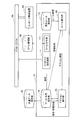
- FIG. 1 is a diagram showing an example of the overall configuration of the maintenance management system of the present embodiment.
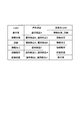
- FIG. 2 is a diagram showing an example of a table held by the label management unit.
- FIG. 3 is a diagram showing a configuration example of operating parts included in the maintenance management system.
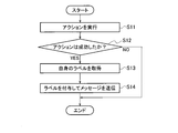
- FIG. 4 is a flowchart showing a processing flow when the operating component receives the message.
- FIG. 5 is a flowchart showing a processing flow of the message control device.
- FIG. 6 is a diagram for explaining the flow of messages between function types.
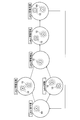
- FIG. 7 is a diagram for explaining a flow of messages between operating components.
- FIG. 8 is a diagram showing an example of the hardware configuration of the operation component and the message control device.
- the maintenance management system of this embodiment will be described with reference to FIG.
- operating components 10-1 to 10-6 which are not connected to each other, actively check the status of services and alarms, and autonomously determine and execute necessary processing.
- the autonomous control loop method is adopted.
- Operational parts 10-1 to 10-6 are devices or processes that operate autonomously. Each of the operation parts 10-1 to 10-6 is made into parts in units of maintenance functions, and each of them has a specific maintenance function. For example, operational components 10-1 to 10-6 are classified into six functional types: information collection, information processing, information analysis, testing, recovery measures, and maintenance personnel. The outline of each type of operational parts is shown below.
- [Information collection] Collect information from the service environment to be maintained.
- [Information processing] Irreversible time series / character string processing and visualization such as noise removal, correlation calculation, feature / keyword extraction, and statistical processing are performed.
- Information analysis Information analysis such as classification, prediction, and state estimation for abnormality judgment and clustering, and generation of analysis results are performed.
- [Test] Generate and send test traffic.
- [Recovery action] Perform an operation to recover the service.
- [Maintenance person] Provide a user interface for the maintenance person to control the operation parts.
- the maintenance management system may not include all the operation parts of the above six function types, or may include operation parts other than the above six function types. Further, the maintenance management system may include a plurality of operation parts having the same function type. For example, when maintaining a service provided by linking a plurality of services, each of the plurality of services is provided with an operation component of the above-mentioned function type.
- the operation parts 10 may be simply referred to.
- Operation component 10 executes an action when it receives a message addressed to itself.
- the action indicates the operation content of the operation component 10, and corresponds to each function when the operation component 10 is made into a component in units of maintenance functions.
- the common data storage unit 20 holds information that is commonly used by each of the operation components 10.
- the operation component 10 stores information in the common data storage unit 20 or acquires information from the common data storage unit 20.
- the operation component 10 When the operation component 10 succeeds in executing the action, the operation component 10 sends a message to the message bus 30. If the operation component 10 fails to execute the action, the operation component 10 completes the operation without sending a message.
- the operation component 10 attaches a label assigned to the operation component 10 itself to the message.
- a label is assigned to each operation component 10 for each function type. For example, the operation component 10-1 is given an "information gathering" label.
- each of the operation parts 10-1 to 10-6 has an "information gathering" label, an "information processing” label, an "information analysis” label, a "test” label, a "recovery action” label, and a "maintenance person". Labeled.
- One label may be attached to a plurality of operating parts 10.
- the message control device 40 receives the message from the message bus 30, determines the destination of the message based on the label given to the message, and multicasts to one or more operation components 10. That is, in the present embodiment, the message is not broadcast to all the operating components 10.
- the label management unit 50 manages a label assignment rule in which labels for each function type are assigned to each operation component 10 and a message transmission rule in which a destination is determined from the source label.
- FIG. 2 shows an example of a table managed by the label management unit 50.
- the assignment of labels to operation parts A to J for each function type is managed.
- the "maintenance person" label is the operation part A
- the "information gathering” label is the operation part B and the operation part C
- the "test” label is the operation part D and the operation part E
- the "information processing” label is the operation part.
- the "information analysis” label is assigned to the operation component G and the operation component H
- the "recovery action” label is assigned to the operation component I and the operation component J.
- the operating parts A to J are, for example, identifiers for identifying the operating parts 10.
- the relationship between the label of the sender and the label of the sender given to the message is managed. Specifically, messages with the sender "maintenance" label are sent to the "information gathering" label and "test” label, and messages with the destination "information gathering” label are sent to the "information processing” label. For messages with the "test” label as the destination, the "information processing" label is the destination, for messages with the "information processing” label as the destination, the "information analysis” label is the destination, and the destination is "information analysis”. It is decided that the label message is sent to the "recovery action” label, and the message to which the destination is the "recovery action” label is sent to the "maintenance person” label.
- the message transmitted by the operation component A is given the "maintenance person” label to the sender.
- a message with the "maintenance person” label attached to the sender is given the "information gathering” label and the "test” label to the destination.
- the "information gathering” label is assigned to the operation component B and the operation component C
- the "test” label is assigned to the operation component D and the operation component E. That is, the message transmitted by the operation component A is transmitted to the operation component B and the operation component C, and the operation component D and the operation component E.
- the operation parts 10-1 to 10-6 in FIG. 1 have the same configuration as the operation parts 10 shown in FIG.
- the operation component 10 includes a message transmission / reception unit 11, a data / state storage unit 12, an ignition rule storage unit 13, a rule execution unit 14, and an action execution unit 15.
- the message transmission / reception unit 11 receives a message addressed to itself with a label assigned to the operation component 10 itself attached to the destination via the message bus 30. Further, when the action by the action execution unit 15 succeeds, the message transmission / reception unit 11 creates a message based on the execution result of the action and transmits it to the message bus 30. If the action by the action execution unit 15 fails, the message transmission / reception unit 11 does not send a message.
- the label assignment unit 111 acquires the label assigned to the operation component 10 itself from the label management unit 50, and sends the label assigned to the operation component 10 itself to the message transmission source. Give.
- the data / state storage unit 12 holds data and a state such as a received message and an execution result of the action execution unit 15.
- the data / state storage unit 12 may hold the data acquired from the common data storage unit 20, or temporarily holds the data stored in the common data storage unit 20 and stores the data in the common data storage unit 20. May be stored.
- the data and state held by the data / state storage unit 12 may be used when the action execution unit 15 executes an action.
- the ignition rule storage unit 13 holds an ignition rule in which information for specifying an action to be executed is individually defined for each operation component 10.
- the firing rule may specify an action to take depending on the label of the source of the received message.
- an operational component 10 labeled "Information Processing” has a firing rule that specifies an action to be taken when the source receives a message labeled "Information Collection” and a message labeled "Test” by the source. Holds a firing rule that specifies the action to take when a is received.
- the rule execution unit 14 fires all the received messages and instructs the action execution unit 15 to execute the action. Specifically, when the message transmission / reception unit 11 receives a message addressed to itself, the rule execution unit 14 acquires the ignition rule stored in the ignition rule storage unit 13 and notifies the action execution unit 15 of the action to be executed. do.
- the action execution unit 15 receives an instruction from the rule execution unit 14, refers to the data held by the data / state storage unit 12 and the data held by the common data storage unit 20, and notifies the action from the rule execution unit 14. To execute. If the action by the action execution unit 15 is successful, the message transmission / reception unit 11 transmits a message with its own label to the sender. The action by the action execution unit 15 may fail due to factors such as lack of data. If the action execution unit 15 fails to execute the action, no message is sent.
- step S11 the operation component 10 executes a designated action.
- step S12 the operation component 10 determines whether or not the execution of the action is successful. If the execution of the action fails, the operation component 10 completes the operation.
- step S13 the operation component 10 acquires the label assigned to itself from the label management unit 50.
- step S14 the operation component 10 transmits a message with the acquired label attached to the sender.
- step S21 the message control device 40 receives the message transmitted by the operation component 10.
- step S22 the message control device 40 acquires the destination label for the sender label attached to the message from the label management unit 50.
- step S23 the message control device 40 transmits a message to the operation component 10 to which the label of the transmission destination is assigned.
- the operation component 10 receives the message and starts the process of FIG.
- the processes of FIGS. 4 and 5 are repeated, and the operation component 10 divided according to the function operates autonomously.
- the label management unit 50 assigns labels for each function type to each of the operation parts A to J, and maintains the relationship between the source label and the destination label. ..
- a message with the "maintenance person" label attached to the sender can be referred to as operation parts B and C to which the "information gathering" label and the "test” label are assigned to the destination and the "information gathering” label is assigned.
- the "test” label is sent to the assigned operational components D and E.
- a message to which the "information processing" label is attached to the transmission source is transmitted to the operation parts G and H to which the "information analysis” label is attached to the destination and the "information analysis” label is assigned.
- a message with the "information analysis” label attached to the sender is sent to the operation parts I and J to which the "recovery action” label is given to the destination and the "recovery action” label is assigned.
- a message to which the "recovery action" label is attached to the sender is sent to the operation component A to which the "maintenance person” label is attached to the destination and the "maintenance person” label is assigned.
- FIG. 6 shows that the operation parts A, C, D, F, H, and J succeeded in executing the action, and the operation parts B, E, G, and I failed to execute the action.
- Each operating component A, C, D, F, H, J that succeeds in executing the action sends a message.
- step S101 the operation component A transmits a message with the "maintenance person" label attached to the sender.
- the maintenance manager notifies the maintenance management system of the failure using the user interface provided by the operation component A, and the operation component A executes an action and sends a message.
- This message includes, for example, information such as information collection target, information collection content, test target, and test content according to the failure that has occurred.
- the message control device 40 receives the message transmitted by the operation component A from the message bus 30, and the transmission source acquires the "information collection” label and the "test” label as the destination for the "maintenance person” label.
- step S102 the message control device 40 assigns an "information collection” label and a "test” label to the destination of the message, and transmits the message to the operation components B and C and the operation components D and E.
- the operation parts B and C and the operation parts D and E that received the message execute the action.
- the operation component C and the operation component D succeed in executing the action
- the operation component B and the operation component E fail to execute the action.
- Operation component B and operation component E complete the operation without transmitting a message.
- the operation component B fails to execute the action because the maintenance manager does not collect the information of the target to be collected, and the operation component E does not execute the test desired by the maintenance manager, so the action is executed. Failed.
- the operation component C collected information from the information collection target, and the operation component D was tested on the test target.
- step S103 the operation component C transmits a message with the "information collection" label attached to the sender. For example, the operation component C transmits a message indicating that the information collection from the information collection target is completed.
- step S104 the operation component D transmits a message with the "test" label attached to the sender. For example, the operation component D transmits a message indicating that the test for the test target has been completed.
- the message control device 40 receives the message transmitted by the operation component C from the message bus 30, and the transmission source acquires the "information processing" label as the destination for the "information collection” label. Further, the message control device 40 receives the message transmitted by the operation component D from the message bus 30, and the transmission source acquires the "information processing" label as the transmission destination for the "test" label.
- step S105 the message control device 40 assigns an "information processing" label to each destination of the message transmitted by the operation component C and the message transmitted by the operation component D, and transmits these messages to the operation component F. do.
- the operation component F that received the message executes the action.
- step S106 the operation component F transmits a message with the "information processing" label attached to the sender.
- the operation component F processes the collected information, processes the test result, and transmits a message indicating that the processing of the information is completed.
- the operation component F may send a message after processing the collected information and after processing the test result, or after both the processing of the collected information and the processing of the test result are completed. May be sent.
- the message control device 40 receives the message transmitted by the operation component F from the message bus 30, and the transmission source acquires the "information analysis" label as the destination for the "information processing" label.
- step S107 the message control device 40 assigns an "information analysis" label to the destination of the message transmitted in step S106, and transmits the message to the operation components G and H.
- the operational parts G and H that received the message execute the action. It is assumed that the operation component H succeeds in executing the action, and the operation component G fails to execute the action.
- step S108 the operation component H transmits a message with the "information analysis" label attached to the sender. For example, the operation component H transmits a message including the information analysis result.
- the message control device 40 receives the message transmitted by the operation component H from the message bus 30, and the source acquires the "recovery action" label as the destination for the "information analysis” label.
- step S109 the message control device 40 assigns a "recovery action" label to the destination of the message transmitted in step S108, and transmits the message to the operation components I and J.
- Operation parts I and J that received the message execute the action. It is assumed that the operation component J succeeds in executing the action, and the operation component I fails to execute the action.
- step S110 the operation component J transmits a message with the "recovery action" label attached to the sender. For example, the operation component J selects a recovery action based on the analysis result, sends a message indicating the selected recovery action and obtains the approval of the maintenance manager, or sends a message including the result of executing the recovery action. Send it.
- the message control device 40 receives the message transmitted by the operation component J from the message bus 30, and the source acquires the "maintenance person" label as the destination for the "recovery action” label.
- step S111 the message control device 40 assigns a "maintenance person" label to the destination of the message transmitted in step S110, and transmits the message to the operation component A.
- the message control device 40 controls the destination of the message based on the label of the source of the message, and the operation parts A to J that have received the message execute an action to send the message for maintenance management. Maintenance operations by the system are performed.
- the operation component 10 transmits a message with a label assigned to the sender, and the message control device 40 is assigned to the sender of the message.
- the destination label for the label is acquired, a message is sent to the operation component 10 to which the destination label is assigned, and the operation component 10 that receives the message executes the action, and when the action is successful, a message is sent.
- Send Since the operation component 10 operates based on the label attached to the message, not the information unique to the operation component, even if a new operation component 10 is added or the operation component 10 is repaired, the existing operation is performed. The influence on the component 10 can be reduced.
- the operation component 10 and the message control device 40 described above include, for example, a central processing unit (CPU) 901, a memory 902, a storage 903, a communication device 904, and an input device 905 as shown in FIG. ,
- a general-purpose computer system including an output device 906 can be used.
- the operation component 10 and the message control device 40 are realized by the CPU 901 executing a predetermined program loaded on the memory 902.
- This program can be recorded on a computer-readable recording medium such as a magnetic disk, an optical disk, or a semiconductor memory, or can be distributed via a network.
Landscapes
- Engineering & Computer Science (AREA)
- Business, Economics & Management (AREA)
- Human Resources & Organizations (AREA)
- Theoretical Computer Science (AREA)
- General Physics & Mathematics (AREA)
- Quality & Reliability (AREA)
- Physics & Mathematics (AREA)
- Marketing (AREA)
- Operations Research (AREA)
- Strategic Management (AREA)
- Tourism & Hospitality (AREA)
- General Business, Economics & Management (AREA)
- Entrepreneurship & Innovation (AREA)
- Economics (AREA)
- General Engineering & Computer Science (AREA)
- Management, Administration, Business Operations System, And Electronic Commerce (AREA)
- Debugging And Monitoring (AREA)
Abstract
メッセージを送受信して自律的に動作する複数の運用部品10と運用部品10間で送受信されるメッセージを制御するメッセージ制御装置40を備えてサービスを保守管理する保守管理システムである。運用部品10は、自分宛てのメッセージを受信すると所定のアクションを実行し、アクションの実行が成功した場合、送信元に自身に割り当てられたラベルを付与したメッセージを送信する。メッセージ制御装置40は、運用部品10の送信したメッセージを受信し、メッセージの送信元に付与されたラベルから送信先の運用部品10を決定し、メッセージを送信先の運用部品10へ送信する。
Description
本発明は、保守管理システム、メッセージ制御装置、メッセージ制御方法、およびプログラムに関する。
ネットワーク環境の普及により、ネットワークを介して提供されるサービスの利用が拡大している。サービスの品質および障害発生の有無を監視し、必要に応じて解析および復旧を行うサービス保守作業が行われている。サービス保守作業は、作業者の知見とノウハウに基づく判断が中心となって実現されており手間や時間がかかる。特に近年は、B2B2Xの普及に伴い、複数サービスを連携させて提供するサービスが増加している。サービス保守作業も複数サービスを連携した保守および運用が必要となっている。
非特許文献1には、サービス保守作業を自動化する技術として、保全オペレーションの機能を部品化し、自律化することで、新たな運用部品をシステムに組み込むだけで自律的に動作を決定する自律制御ループ方式が提案されている。自律制御ループ方式では、機能別に分けられた運用部品間でメッセージを送受信する。各運用部品は、受信したメッセージに基づいて自律的に動作する。
丹治直幸、外2名、「保守機能の部品化と自律化による自律制御ループ方式の提案」、電子情報通信学会技術研究報告、一般社団法人電子情報通信学会、2018年7月, Vol. 118, No. 118, pp. 13-18
従来の自動制御ループ方式では、メッセージは全ての運用部品へブロードキャストされる。運用部品は、メッセージと自身の保持する発火ルールに基づき、アクションを実行するか、何もしないかを決定する。発火ルールには、運用部品固有の条件と実行するアクションが設定されている。運用部品は、受け取ったメッセージに対して発火ルールの条件を満たす場合に所定のアクションを実行し、アクション実行後にメッセージを送信する。メッセージには、運用部品固有の実行結果に基づく内容が付与される。メッセージは、全ての運用部品へブロードキャストされて、各運用部品はメッセージを受信して発火ルールに基づいて自律的に動作する。
新たな運用部品を追加したり、運用部品を改修したりするときに、発火ルールに設定されている運用部品固有の条件または実行するアクション内容に変更が生じると、関連する他の運用部品を改修する必要があった。短期間で新たな運用部品の追加および運用部品の改修ができれば、新サービスへの対応およびサービスの仕様変更にタイムリーに追従できる。
本発明は、上記に鑑みてなされたものであり、自動制御ループ方式において運用部品の追加および改修の影響を軽減することを目的とする。
本発明の一態様の保守管理システムは、メッセージを送受信して自律的に動作する複数の運用部品装置と前記運用部品装置間で送受信されるメッセージを制御するメッセージ制御装置を備えてサービスを保守管理する保守管理システムであって、前記運用部品装置は、 自分宛てのメッセージを受信すると所定のアクションを実行し、前記アクションの実行が成功した場合、送信元に自身に割り当てられたラベルを付与したメッセージを送信し、前記メッセージ制御装置は、前記運用部品装置の送信したメッセージを受信し、前記メッセージの送信元に付与されたラベルから送信先の前記運用部品装置を決定し、前記メッセージを送信先の前記運用部品装置へ送信する。
本発明によれば、自動制御ループ方式において運用部品の追加および改修の影響を軽減することができる。
図1を参照し、本実施形態の保守管理システムについて説明する。本実施形態の保守管理システムは、互いに接続関係を持たない運用部品10-1~10-6が、能動的にサービスおよびアラームの状況を確認し、必要な処理を自律的に判断して実行する自律制御ループ方式を採用している。
運用部品10-1~10-6は、自律的に動作する装置またはプロセスである。運用部品10-1~10-6のそれぞれは、保守機能の単位で部品化されたものであり、各自が特定の保守機能を有する。例えば、運用部品10-1~10-6は、情報収集、情報加工、情報解析、試験、回復処置、および保守者の6つの機能種別に分類される。各種別の運用部品の概要を以下に示す。
[情報収集]保守対象のサービス環境から情報収集を行う。
[情報加工]ノイズ除去、相関関係算出、特徴・キーワード抽出、および統計処理など不可逆的な時系列・文字列処理と可視化を行う。
[情報解析]異常判定やクラスタリングのための分類、予測、および状態推定などの情報解析と解析結果の生成を行う。
[試験]試験トラフィックの生成と送信を行う。
[回復処置]サービスを回復するためのオペレーションを行う。
[保守者]保守者が運用部品を制御するためのユーザインタフェースを提供する。
[情報加工]ノイズ除去、相関関係算出、特徴・キーワード抽出、および統計処理など不可逆的な時系列・文字列処理と可視化を行う。
[情報解析]異常判定やクラスタリングのための分類、予測、および状態推定などの情報解析と解析結果の生成を行う。
[試験]試験トラフィックの生成と送信を行う。
[回復処置]サービスを回復するためのオペレーションを行う。
[保守者]保守者が運用部品を制御するためのユーザインタフェースを提供する。
なお、保守管理システムは、上記の6つの機能種別の運用部品を全て備えなくてもよいし、上記の機能種別以外の運用部品を備えてもよい。また、保守管理システムは、同じ機能種別の運用部品を複数備えてもよい。例えば、複数のサービスを連携させて提供されるサービスを保守する場合、複数のサービスのそれぞれについて、上記の機能種別の運用部品を備える。以下、運用部品10-1~10-6の機能種別を区別する必要がない場合は、単に運用部品10と称することもある。
運用部品10は、自分宛てのメッセージを受信するとアクションを実行する。アクションとは、運用部品10の動作内容を示すものであり、運用部品10を保守機能の単位で部品化したときの各機能に相当する。共通データ保存部20は、運用部品10のそれぞれで共通的に活用する情報を保持する。運用部品10は、アクションを実行する際、共通データ保存部20に情報を保存したり、共通データ保存部20から情報を取得したりする。
運用部品10は、アクションの実行に成功した場合、メッセージバス30に対してメッセージを送信する。運用部品10は、アクションの実行に失敗した場合、メッセージを送信せずに動作を完了する。運用部品10は、メッセージを送信する際、運用部品10自身に割り当てられたラベルをメッセージに付与する。各運用部品10には、機能種別ごとにラベルが割り当てられている。例えば、運用部品10-1には、「情報収集」ラベルが付与される。例えば、運用部品10-1~10-6のそれぞれには、「情報収集」ラベル、「情報加工」ラベル、「情報解析」ラベル、「試験」ラベル、「回復処置」ラベル、および「保守者」ラベルが付与される。1つのラベルを複数の運用部品10に付与してもよい。
メッセージ制御装置40は、メッセージバス30からメッセージを受信し、メッセージに付与されたラベルに基づいてメッセージの送信先を決定し、1つ以上の運用部品10に対してマルチキャストする。つまり、本実施形態では、メッセージは全ての運用部品10に対してブロードキャストされない。
ラベル管理部50は、機能種別ごとのラベルを各運用部品10への割り当てたラベル付与ルールと、送信元のラベルから送信先を決めるメッセージ送信ルールを管理する。
図2に、ラベル管理部50の管理するテーブルの一例を示す。図2のテーブルでは、機能種別ごとのラベルの運用部品A~Jへの割り当てが管理されている。具体的には、「保守者」ラベルは運用部品A、「情報収集」ラベルは運用部品Bと運用部品C、「試験」ラベルは運用部品Dと運用部品E、「情報加工」ラベルは運用部品F、「情報解析」ラベルは運用部品Gと運用部品H、「回復処置」ラベルは運用部品Iと運用部品Jに割り当てられている。運用部品A~Jは、例えば、運用部品10を識別するための識別子である。
また、図2のテーブルでは、メッセージに付与された送信元のラベルに対する送信先のラベルの関係が管理されている。具体的には、送信元が「保守者」ラベルのメッセージは「情報収集」ラベルと「試験」ラベルを送信先とし、送信先が「情報収集」ラベルのメッセージは「情報加工」ラベルを送信先とし、送信先が「試験」ラベルのメッセージは「情報加工」ラベルを送信先とし、送信先が「情報加工」ラベルのメッセージは「情報解析」ラベルを送信先とし、送信先が「情報解析」ラベルのメッセージは「回復処置」ラベルを送信先とし、送信先が「回復処置」ラベルのメッセージは「保守者」ラベルを送信先とすることが決められている。
図2のテーブルの例では、運用部品Aが送信するメッセージには、送信元に「保守者」ラベルが付与される。送信元に「保守者」ラベルが付与されたメッセージは、送信先に「情報収集」ラベルと「試験」ラベルが付与される。「情報収集」ラベルは運用部品Bと運用部品Cに割り当てられ、「試験」ラベルは運用部品Dと運用部品Eに割り当てられている。つまり、運用部品Aが送信したメッセージは、運用部品Bと運用部品C、ならびに運用部品Dと運用部品Eに送信される。
図3を参照し、保守管理システムが備える運用部品の構成について説明する。図1の運用部品10-1~10-6は、図3に示す運用部品10と同じ構成である。
運用部品10は、メッセージ送受信部11、データ・状態保存部12、発火ルール保存部13、ルール実行部14、およびアクション実行部15を備える。
メッセージ送受信部11は、メッセージバス30を介して、運用部品10自身に割り当てられたラベルが送信先に付与された自分宛てのメッセージを受信する。また、メッセージ送受信部11は、アクション実行部15によるアクションが成功した場合に、アクションの実行結果に基づいたメッセージを作成し、メッセージバス30に送信する。アクション実行部15によるアクションが失敗した場合は、メッセージ送受信部11は、メッセージを送信しない。
メッセージ送受信部11がメッセージを送信する際、ラベル付与部111は、ラベル管理部50から運用部品10自身に割り当てられたラベルを取得し、メッセージの送信元に運用部品10自身に割り当てられたラベルを付与する。
データ・状態保存部12は、受信したメッセージ、アクション実行部15の実行結果などのデータおよび状態を保持する。データ・状態保存部12は、共通データ保存部20から取得したデータを保持してもよいし、共通データ保存部20に格納するデータを一時的に保持して、共通データ保存部20にデータを格納してもよい。データ・状態保存部12の保持するデータおよび状態は、アクション実行部15がアクションを実行する際に利用してもよい。
発火ルール保存部13は、実行するアクションを指定する情報を運用部品10ごとに個別に定義した発火ルールを保持する。発火ルールは、受信したメッセージの送信元のラベルに応じて実行するアクションを指定してもよい。例えば、「情報加工」ラベルを付与された運用部品10は、送信元が「情報収集」ラベルのメッセージを受信したときに実行するアクションを指定する発火ルールと、送信元が「試験」ラベルのメッセージを受信したときに実行するアクションを指定する発火ルールを保持する。
ルール実行部14は、受信したメッセージのすべてに発火し、アクション実行部15にアクションの実行を指示する。具体的には、メッセージ送受信部11が自分宛てのメッセージを受信すると、ルール実行部14は、発火ルール保存部13に保存されている発火ルールを取得し、アクション実行部15に実行するアクションを通知する。
アクション実行部15は、ルール実行部14からの指示を受けて、データ・状態保存部12が保持するデータおよび共通データ保存部20が保持するデータを参照し、ルール実行部14から通知されたアクションを実行する。アクション実行部15によるアクションが成功すると、メッセージ送受信部11により送信元に自身のラベルが付与されたメッセージが送信される。アクション実行部15によるアクションはデータ不足などの要因で失敗することがある。アクション実行部15がアクションの実行に失敗した場合は、メッセージは送信されない。
次に、運用部品10とメッセージ制御装置40の動作について説明する。
まず、図4のフローチャートを参照し、運用部品10がメッセージを受信したときの動作について説明する。運用部品10は、自分宛てのメッセージを受信すると、図4の処理を開始する。
ステップS11にて、運用部品10は、指定のアクションを実行する。
ステップS12にて、運用部品10は、アクションの実行が成功したか否か判定する。アクションの実行が失敗した場合、運用部品10は動作を完了する。
アクションの実行が成功した場合、ステップS13にて、運用部品10は、ラベル管理部50から自身に割り当てられたラベルを取得する。
ステップS14にて、運用部品10は、取得したラベルを送信元に付与したメッセージを送信する。
続いて、図5のフローチャートを参照し、メッセージ制御装置40の動作について説明する。
ステップS21にて、メッセージ制御装置40は、運用部品10の送信したメッセージを受信する。
ステップS22にて、メッセージ制御装置40は、メッセージに付与されている送信元のラベルに対する送信先のラベルをラベル管理部50から取得する。
ステップS23にて、メッセージ制御装置40は、送信先のラベルを割り当てられた運用部品10へメッセージを送信する。
その後、運用部品10はメッセージを受信して図4の処理を開始する。図4,5の処理が繰り返されて、機能別に分けられた運用部品10が自律的に動作する。
次に、本実施形態の保守管理システムにおけるメッセージの流れについて説明する。
ラベル管理部50は、図2のテーブルに示したように、機能種別ごとのラベルを各運用部品A~Jに割り当て、送信元のラベルに対する送信先のラベルの関係を保持しているものとする。
ラベル管理部50が図2のテーブルを保持する場合、機能種別ごとに分けられた運用部品10間のメッセージの流れは、図6に示すようになる。図6では、矢印を用いて図2のテーブルで管理されるメッセージの送信ルールを示している。
例えば、送信元に「保守者」ラベルが付与されたメッセージは、送信先に「情報収集」ラベルおよび「試験」ラベルが付与されて、「情報収集」ラベルが割り当てられた運用部品B,Cと「試験」ラベルが割り当てられた運用部品D,Eに送信される。
送信元に「情報収集」ラベルが付与されたメッセージおよび送信元に「試験」ラベルが付与されたメッセージは、送信先に「情報加工」ラベルが付与されて、「情報加工」ラベルが割り当てられた運用部品Fに送信される。
送信元に「情報加工」ラベルが付与されたメッセージは、送信先に「情報解析」ラベルが付与されて、「情報解析」ラベルが割り当てられた運用部品G,Hに送信される。
送信元に「情報解析」ラベルが付与されたメッセージは、送信先に「回復処置」ラベルが付与されて、「回復処置」ラベルが割り当てられた運用部品I,Jに送信される。
送信元に「回復処置」ラベルが付与されたメッセージは、送信先に「保守者」ラベルが付与されて、「保守者」ラベルが割り当てられた運用部品Aに送信される。
なお、図6では、運用部品A,C,D,F,H,Jはアクションの実行に成功し、運用部品B,E,G,Iはアクションの実行に失敗したことを示している。アクションの実行に成功した各運用部品A,C,D,F,H,Jがメッセージを送信する。
図7を参照し、各運用部品A~Jが送受信するメッセージの流れについて説明する。
まず、ステップS101にて、運用部品Aは送信元に「保守者」ラベルを付与したメッセージを送信する。例えば、障害発生時、保守管理者が、運用部品Aの提供するユーザインタフェースを利用して、障害発生を保守管理システムに通知すると、運用部品Aは、アクションを実行し、メッセージを送信する。このメッセージは、例えば、発生した障害に応じた、情報収集対象、情報収集内容、試験対象、および試験内容などの情報を含む。
メッセージ制御装置40は、運用部品Aの送信したメッセージをメッセージバス30から受信し、送信元が「保守者」ラベルに対する送信先として「情報収集」ラベルおよび「試験」ラベルを取得する。
ステップS102にて、メッセージ制御装置40は、メッセージの送信先に「情報収集」ラベルおよび「試験」ラベルを付与し、運用部品B,Cおよび運用部品D,Eにメッセージを送信する。
メッセージを受信した運用部品B,Cおよび運用部品D,Eは、アクションを実行する。このうち、運用部品Cと運用部品Dはアクションの実行に成功し、運用部品Bと運用部品Eはアクションの実行に失敗したとする。運用部品Bと運用部品Eはメッセージを送信せずに動作を完了する。例えば、運用部品Bは保守管理者が情報収集したい対象の情報収集を行うものではないのでアクションの実行に失敗し、運用部品Eは保守管理者が望む試験を実行するものではないのでアクションの実行に失敗した。運用部品Cは、情報収集対象から情報収集し、運用部品Dは、試験対象に試験をした。
運用部品Cはアクションの実行に成功すると、ステップS103にて、送信元に「情報収集」ラベルを付与したメッセージを送信する。例えば、運用部品Cは、情報収集対象からの情報収集が完了したことを示すメッセージを送信する。
運用部品Dはアクションの実行に成功すると、ステップS104にて、送信元に「試験」ラベルを付与したメッセージを送信する。例えば、運用部品Dは、試験対象に対する試験が完了したことを示すメッセージを送信する。
メッセージ制御装置40は、運用部品Cの送信したメッセージをメッセージバス30から受信し、送信元が「情報収集」ラベルに対する送信先として「情報加工」ラベルを取得する。また、メッセージ制御装置40は、運用部品Dの送信したメッセージをメッセージバス30から受信し、送信元が「試験」ラベルに対する送信先として「情報加工」ラベルを取得する。
ステップS105にて、メッセージ制御装置40は、運用部品Cの送信したメッセージと運用部品Dの送信したメッセージのそれぞれの送信先に「情報加工」ラベルを付与し、運用部品Fにこれらのメッセージを送信する。
メッセージを受信した運用部品Fはアクションを実行する。
運用部品Fはアクションの実行に成功すると、ステップS106にて、送信元に「情報加工」ラベルを付与したメッセージを送信する。例えば、運用部品Fは、収集された情報を加工するとともに、試験結果を加工し、情報の加工が完了したことを示すメッセージを送信する。運用部品Fは、収集された情報を加工した後と試験結果を加工した後のそれぞれでメッセージを送信してもよいし、収集された情報の加工と試験結果の加工の両方が完了した後にメッセージを送信してもよい。
メッセージ制御装置40は、運用部品Fの送信したメッセージをメッセージバス30から受信し、送信元が「情報加工」ラベルに対する送信先として「情報解析」ラベルを取得する。
ステップS107にて、メッセージ制御装置40は、ステップS106で送信されたメッセージの送信先に「情報解析」ラベルを付与し、運用部品G,Hにメッセージを送信する。
メッセージを受信した運用部品G,Hはアクションを実行する。運用部品Hはアクションの実行に成功し、運用部品Gはアクションの実行に失敗したとする。
運用部品Hはアクションの実行に成功すると、ステップS108にて、送信元に「情報解析」ラベルを付与したメッセージを送信する。例えば、運用部品Hは、情報解析結果を含むメッセージを送信する。
メッセージ制御装置40は、運用部品Hの送信したメッセージをメッセージバス30から受信し、送信元が「情報解析」ラベルに対する送信先として「回復処置」ラベルを取得する。
ステップS109にて、メッセージ制御装置40は、ステップS108で送信されたメッセージの送信先に「回復処置」ラベルを付与し、運用部品I,Jへ送信する。
メッセージを受信した運用部品I,Jはアクションを実行する。運用部品Jはアクションの実行に成功し、運用部品Iはアクションの実行に失敗したとする。
運用部品Jはアクションの実行に成功すると、ステップS110にて、送信元に「回復処置」ラベルを付与したメッセージを送信する。例えば、運用部品Jは、解析結果に基づいて回復処置を選択し、選択した回復処置を示して保守管理者の承認を得るためのメッセージを送信したり、回復処置を実行した結果を含むメッセージを送信したりする。
メッセージ制御装置40は、運用部品Jの送信したメッセージをメッセージバス30から受信し、送信元が「回復処置」ラベルに対する送信先として「保守者」ラベルを取得する。
ステップS111にて、メッセージ制御装置40は、ステップS110で送信されたメッセージの送信先に「保守者」ラベルを付与し、運用部品Aへ送信する。
このように、メッセージ制御装置40がメッセージの送信元のラベルに基づいてメッセージの送信先を制御し、メッセージを受信した運用部品A~Jがアクションを実行してメッセージを送信することで、保守管理システムによる保守オペレーションが実行される。
以上説明したように、本実施形態の保守管理システムでは、運用部品10が、送信元に自身に割り当てられたラベルを付与したメッセージを送信し、メッセージ制御装置40が、メッセージの送信元に付与されたラベルに対する送信先のラベルを取得し、送信先のラベルが割り当てられた運用部品10へメッセージ送信して、メッセージを受信した運用部品10が、アクションを実行し、アクションが成功した場合にメッセージを送信する。運用部品10は、運用部品固有の情報ではなく、メッセージに付与されたラベルに基づいて動作するので、新たな運用部品10が追加されたり、運用部品10が改修されたりした場合でも、既存の運用部品10への影響を軽減できる。
上記説明した運用部品10およびメッセージ制御装置40には、例えば、図8に示すような、中央演算処理装置(CPU)901と、メモリ902と、ストレージ903と、通信装置904と、入力装置905と、出力装置906とを備える汎用的なコンピュータシステムを用いることができる。このコンピュータシステムにおいて、CPU901がメモリ902上にロードされた所定のプログラムを実行することにより、運用部品10およびメッセージ制御装置40が実現される。このプログラムは磁気ディスク、光ディスク、半導体メモリ等のコンピュータ読み取り可能な記録媒体に記録することも、ネットワークを介して配信することもできる。
10-1~10-6,10…運用部品
11…メッセージ送受信部
111…ラベル付与部
12…データ・状態保存部
13…発火ルール保存部
14…ルール実行部
15…アクション実行部
20…共通データ保存部
30…メッセージバス
40…メッセージ制御装置
50…ラベル管理部
11…メッセージ送受信部
111…ラベル付与部
12…データ・状態保存部
13…発火ルール保存部
14…ルール実行部
15…アクション実行部
20…共通データ保存部
30…メッセージバス
40…メッセージ制御装置
50…ラベル管理部
Claims (6)
- メッセージを送受信して自律的に動作する複数の運用部品装置と前記運用部品装置間で送受信されるメッセージを制御するメッセージ制御装置を備えてサービスを保守管理する保守管理システムであって、
前記運用部品装置は、
自分宛てのメッセージを受信すると所定のアクションを実行し、
前記アクションの実行が成功した場合、送信元に自身に割り当てられたラベルを付与したメッセージを送信し、
前記メッセージ制御装置は、
前記運用部品装置の送信したメッセージを受信し、
前記メッセージの送信元に付与されたラベルから送信先の前記運用部品装置を決定し、
前記メッセージを送信先の前記運用部品装置へ送信する
保守管理システム。 - 請求項1に記載の保守管理システムであって、
機能種別ごとのラベルを前記運用部品装置に割り当て、送信元のラベルに対する送信先のラベルの関係を管理するラベル管理装置を備え、
前記メッセージ制御装置は、
前記ラベル管理装置から前記メッセージの送信元に付与されたラベルに対する送信先のラベルを取得し、
前記送信先のラベルが割り当てられた全ての前記運用部品装置へ前記メッセージを送信する
保守管理システム。 - 自律的に動作する複数の運用部品装置間で送受信されるメッセージを制御するメッセージ制御装置であって、
メッセージを受信し、
メッセージの送信元に付与されたラベルから送信先の前記運用部品装置を決定し、
メッセージを送信先の前記運用部品装置へ送信する
メッセージ制御装置。 - 請求項3に記載のメッセージ制御装置であって、
送信元のラベルに対する送信先のラベルの関係を管理するラベル管理装置から前記メッセージの送信元に付与されたラベルに対する送信先のラベルを取得し、
前記送信先のラベルが割り当てられた全ての前記運用部品装置へ前記メッセージを送信する
メッセージ制御装置。 - 自律的に動作する複数の運用部品装置間で送受信されるメッセージを制御するメッセージ制御装置が実行するメッセージ制御方法であって、
メッセージを受信し、
メッセージの送信元に付与されたラベルから送信先の前記運用部品装置を決定し、
メッセージを送信先の前記運用部品装置へ送信する
メッセージ制御方法。 - 請求項3または4に記載のメッセージ制御装置としてコンピュータを動作させるプログラム。
Priority Applications (4)
| Application Number | Priority Date | Filing Date | Title |
|---|---|---|---|
| US17/797,187 US20230053486A1 (en) | 2020-02-05 | 2020-02-05 | Maintenance management system, message control apparatus, message control method, and program |
| JP2021575157A JP7335532B2 (ja) | 2020-02-05 | 2020-02-05 | 保守管理システム、メッセージ制御装置、メッセージ制御方法、およびプログラム |
| PCT/JP2020/004359 WO2021156972A1 (ja) | 2020-02-05 | 2020-02-05 | 保守管理システム、メッセージ制御装置、メッセージ制御方法、およびプログラム |
| JP2023132793A JP7522374B2 (ja) | 2020-02-05 | 2023-08-17 | システム、メッセージ制御装置、メッセージ制御方法、およびプログラム |
Applications Claiming Priority (1)
| Application Number | Priority Date | Filing Date | Title |
|---|---|---|---|
| PCT/JP2020/004359 WO2021156972A1 (ja) | 2020-02-05 | 2020-02-05 | 保守管理システム、メッセージ制御装置、メッセージ制御方法、およびプログラム |
Publications (1)
| Publication Number | Publication Date |
|---|---|
| WO2021156972A1 true WO2021156972A1 (ja) | 2021-08-12 |
Family
ID=77200003
Family Applications (1)
| Application Number | Title | Priority Date | Filing Date |
|---|---|---|---|
| PCT/JP2020/004359 Ceased WO2021156972A1 (ja) | 2020-02-05 | 2020-02-05 | 保守管理システム、メッセージ制御装置、メッセージ制御方法、およびプログラム |
Country Status (3)
| Country | Link |
|---|---|
| US (1) | US20230053486A1 (ja) |
| JP (2) | JP7335532B2 (ja) |
| WO (1) | WO2021156972A1 (ja) |
Citations (5)
| Publication number | Priority date | Publication date | Assignee | Title |
|---|---|---|---|---|
| JP2011239246A (ja) * | 2010-05-12 | 2011-11-24 | Nec Corp | 通信装置、通信システム及びそれらに用いる制御プレーンパス監査方法 |
| JP2012043121A (ja) * | 2010-08-18 | 2012-03-01 | Nippon Telegr & Teleph Corp <Ntt> | 運用管理システム、運用管理方法及び運用管理装置 |
| JP2013106137A (ja) * | 2011-11-11 | 2013-05-30 | Nec Corp | 通信システム、制御プレーンパスの監査方法、通信装置およびネットワーク管理装置 |
| US20170091007A1 (en) * | 2015-09-25 | 2017-03-30 | Annapurna Dasari | Management of a fault condition in a computing system |
| WO2019244733A1 (ja) * | 2018-06-21 | 2019-12-26 | 日本電信電話株式会社 | オペレーション装置、および、オペレーション方法 |
Family Cites Families (15)
| Publication number | Priority date | Publication date | Assignee | Title |
|---|---|---|---|---|
| US20110208567A9 (en) * | 1999-08-23 | 2011-08-25 | Roddy Nicholas E | System and method for managing a fleet of remote assets |
| US20020059075A1 (en) * | 2000-05-01 | 2002-05-16 | Schick Louis A. | Method and system for managing a land-based vehicle |
| WO2005038613A2 (en) * | 2003-10-17 | 2005-04-28 | Hydralift Amclyde, Inc. | Equipment component monitoring and replacement management system |
| US8667123B2 (en) * | 2008-09-29 | 2014-03-04 | Woodhead Industries, Inc. | Microcontroller network diagnostic system |
| WO2012073521A1 (ja) | 2010-12-02 | 2012-06-07 | 日本電気株式会社 | イベント配信システムおよびイベント配信方法 |
| CN104272034B (zh) * | 2012-02-28 | 2017-05-24 | 艾默生电气公司 | Hvac系统远程监视和诊断 |
| US20140101058A1 (en) * | 2012-10-08 | 2014-04-10 | Marc Castel | System and method for providing consumer side maintenance |
| JP6261079B2 (ja) | 2014-04-15 | 2018-01-17 | 国立大学法人東京工業大学 | ワークフロー管理装置、ワークフロー管理方法およびワークフロー管理プログラム |
| WO2015179917A1 (en) * | 2014-05-27 | 2015-12-03 | Resmed Limited | Remote diagnostics of respiratory therapy devices |
| JP6368624B2 (ja) | 2014-11-06 | 2018-08-01 | 日本電信電話株式会社 | 非同期メッセージングサーバ連携方式の評価装置及び評価方法 |
| US10402254B2 (en) * | 2015-11-11 | 2019-09-03 | Seagate Technology Llc | Storage drive monitoring |
| JP7080009B2 (ja) | 2017-01-30 | 2022-06-03 | 株式会社オージス総研 | サーバ装置、制御システム、コンピュータプログラム及び通信方法 |
| JP2019186771A (ja) | 2018-04-11 | 2019-10-24 | 富士通株式会社 | 情報処理装置、分散処理プログラムおよび分散処理システム |
| CA3052379A1 (en) * | 2018-08-14 | 2020-02-14 | Daniel Gaudreault | System and method for remote diagnostics and monitoring of heavy equipment |
| US12072695B2 (en) * | 2019-06-21 | 2024-08-27 | Fisher-Rosemount Systems, Inc. | Enhanced work order generation and tracking system |
-
2020
- 2020-02-05 WO PCT/JP2020/004359 patent/WO2021156972A1/ja not_active Ceased
- 2020-02-05 JP JP2021575157A patent/JP7335532B2/ja active Active
- 2020-02-05 US US17/797,187 patent/US20230053486A1/en not_active Abandoned
-
2023
- 2023-08-17 JP JP2023132793A patent/JP7522374B2/ja active Active
Patent Citations (5)
| Publication number | Priority date | Publication date | Assignee | Title |
|---|---|---|---|---|
| JP2011239246A (ja) * | 2010-05-12 | 2011-11-24 | Nec Corp | 通信装置、通信システム及びそれらに用いる制御プレーンパス監査方法 |
| JP2012043121A (ja) * | 2010-08-18 | 2012-03-01 | Nippon Telegr & Teleph Corp <Ntt> | 運用管理システム、運用管理方法及び運用管理装置 |
| JP2013106137A (ja) * | 2011-11-11 | 2013-05-30 | Nec Corp | 通信システム、制御プレーンパスの監査方法、通信装置およびネットワーク管理装置 |
| US20170091007A1 (en) * | 2015-09-25 | 2017-03-30 | Annapurna Dasari | Management of a fault condition in a computing system |
| WO2019244733A1 (ja) * | 2018-06-21 | 2019-12-26 | 日本電信電話株式会社 | オペレーション装置、および、オペレーション方法 |
Also Published As
| Publication number | Publication date |
|---|---|
| US20230053486A1 (en) | 2023-02-23 |
| JP2023159262A (ja) | 2023-10-31 |
| JPWO2021156972A1 (ja) | 2021-08-12 |
| JP7335532B2 (ja) | 2023-08-30 |
| JP7522374B2 (ja) | 2024-07-25 |
Similar Documents
| Publication | Publication Date | Title |
|---|---|---|
| US10771323B2 (en) | Alarm information processing method, related device, and system | |
| CN110928774A (zh) | 一种基于节点式的自动化测试系统 | |
| CN119011374B (zh) | 一种基于设备同步的主备切换方法及系统 | |
| US20120047249A1 (en) | Method of determining equivalent subsets of agents to gather information for a fabric | |
| CN117851122A (zh) | 一种云环境下电力信息系统容灾备份恢复系统 | |
| US11349730B2 (en) | Operation device and operation method | |
| CN111181775B (zh) | 基于自动发现主机资产的一体化运维管理告警方法 | |
| CN117632753A (zh) | 一种自动化智能运维平台 | |
| JP7522374B2 (ja) | システム、メッセージ制御装置、メッセージ制御方法、およびプログラム | |
| CN110609761B (zh) | 确定故障源的方法、装置、存储介质和电子设备 | |
| CN116016123A (zh) | 故障处理方法、装置、设备及介质 | |
| US20120210176A1 (en) | Method for controlling information processing apparatus and information processing apparatus | |
| CN112988828B (zh) | 消息推送方法及电子设备 | |
| CN120276753A (zh) | 服务器集群的维护方法、装置、电子设备及存储介质 | |
| CN112422349A (zh) | 面向nfv的网管系统、方法、设备及介质 | |
| CN116400987B (zh) | 持续集成方法、装置、电子设备及存储介质 | |
| US12332736B2 (en) | Network management apparatus, network management method and network management system | |
| JP7389370B2 (ja) | 運用装置、保守管理システム、運用方法およびプログラム | |
| JP7678046B2 (ja) | ラベル管理システム | |
| CN106970817B (zh) | 故障确定方法及装置 | |
| JP7510335B2 (ja) | 自動化システム、サーバ、自動化方法及びコンピュータプログラム | |
| CN109120368B (zh) | 一种单盘时区设置与自动同步纠正方法 | |
| JP7553841B2 (ja) | 保守システム、情報処理装置、保守方法、およびプログラム | |
| US20230222846A1 (en) | Task managing system for testing-configuring vehicles based on a task order and method thereof | |
| Takahashi et al. | A Workflow-less Autonomous System Architecture for Assurance Operations using Choreography Architecture |
Legal Events
| Date | Code | Title | Description |
|---|---|---|---|
| 121 | Ep: the epo has been informed by wipo that ep was designated in this application |
Ref document number: 20917942 Country of ref document: EP Kind code of ref document: A1 |
|
| ENP | Entry into the national phase |
Ref document number: 2021575157 Country of ref document: JP Kind code of ref document: A |
|
| NENP | Non-entry into the national phase |
Ref country code: DE |
|
| 122 | Ep: pct application non-entry in european phase |
Ref document number: 20917942 Country of ref document: EP Kind code of ref document: A1 |