WO2021153389A1 - 真空防音断熱体およびその製造方法 - Google Patents
真空防音断熱体およびその製造方法 Download PDFInfo
- Publication number
- WO2021153389A1 WO2021153389A1 PCT/JP2021/001928 JP2021001928W WO2021153389A1 WO 2021153389 A1 WO2021153389 A1 WO 2021153389A1 JP 2021001928 W JP2021001928 W JP 2021001928W WO 2021153389 A1 WO2021153389 A1 WO 2021153389A1
- Authority
- WO
- WIPO (PCT)
- Prior art keywords
- heat
- vacuum
- insulation
- manufacturing
- pressure
- Prior art date
Links
Images


Classifications
-
- B—PERFORMING OPERATIONS; TRANSPORTING
- B33—ADDITIVE MANUFACTURING TECHNOLOGY
- B33Y—ADDITIVE MANUFACTURING, i.e. MANUFACTURING OF THREE-DIMENSIONAL [3-D] OBJECTS BY ADDITIVE DEPOSITION, ADDITIVE AGGLOMERATION OR ADDITIVE LAYERING, e.g. BY 3-D PRINTING, STEREOLITHOGRAPHY OR SELECTIVE LASER SINTERING
- B33Y10/00—Processes of additive manufacturing
-
- F—MECHANICAL ENGINEERING; LIGHTING; HEATING; WEAPONS; BLASTING
- F16—ENGINEERING ELEMENTS AND UNITS; GENERAL MEASURES FOR PRODUCING AND MAINTAINING EFFECTIVE FUNCTIONING OF MACHINES OR INSTALLATIONS; THERMAL INSULATION IN GENERAL
- F16L—PIPES; JOINTS OR FITTINGS FOR PIPES; SUPPORTS FOR PIPES, CABLES OR PROTECTIVE TUBING; MEANS FOR THERMAL INSULATION IN GENERAL
- F16L59/00—Thermal insulation in general
- F16L59/06—Arrangements using an air layer or vacuum
- F16L59/065—Arrangements using an air layer or vacuum using vacuum
-
- G—PHYSICS
- G10—MUSICAL INSTRUMENTS; ACOUSTICS
- G10K—SOUND-PRODUCING DEVICES; METHODS OR DEVICES FOR PROTECTING AGAINST, OR FOR DAMPING, NOISE OR OTHER ACOUSTIC WAVES IN GENERAL; ACOUSTICS NOT OTHERWISE PROVIDED FOR
- G10K11/00—Methods or devices for transmitting, conducting or directing sound in general; Methods or devices for protecting against, or for damping, noise or other acoustic waves in general
- G10K11/16—Methods or devices for protecting against, or for damping, noise or other acoustic waves in general
Definitions
- the present invention relates to a vacuum soundproof heat insulating body and a method for manufacturing the same.
- Patent Document 1 Patent Document 1
- Patent Document 2 Patent Document 3
- Patent Document 3 In the vacuum heat insulating material and the double glazing, there is a problem that heat and sound are propagated through the core material and the spacer which are the support portions for holding the vacuum layer without losing the atmospheric pressure.
- JP-A-2004-11705 Japanese Patent Application Laid-Open No. 2008-8311 JP-A-2020-128318
- the present invention has been made in view of the above-mentioned conventional problems, and by reducing the heat and sound propagation of the support portion that supports the vacuum layer, which is the heat insulating layer, and / or by imparting functionality to the support portion, soundproofing performance and thermal management. It is an object of the present invention to provide a vacuum soundproof heat insulating material which is a vacuum heat insulating material whose performance is improved and the range of use is increased, and a method for manufacturing a vacuum soundproof heat insulating body.
- a support part that uses magnetic force with less heat and sound propagation a support part with a structure that reduces heat and sound propagation, or a function to open and close the heat and sound propagation path. If any one or more of the support parts are provided, a vacuum soundproof insulation body, which is a vacuum insulation material that is rich in soundproofing, heat management, and usage range, can be obtained.
- the present invention was completed by finding that there is a method of manufacturing by three-dimensional modeling.
- the inclusions that propagate heat and sound to the vacuum layer can be reduced, and the heat and sound propagation path can be opened and closed.
- a vacuum soundproof insulation can be obtained.
- FIG. 1 Schematic diagram of the vacuum soundproof insulation body of the example
- FIG. 1 Schematic diagram of the vacuum soundproof insulation body of the example
- FIG. 1 Schematic diagram of the vacuum soundproof insulation body of the example
- FIG. 1 Schematic diagram of the vacuum soundproof insulation body of the example
- FIG. 1 Schematic diagram of the vacuum soundproof insulation body of the example
- FIG. 1 Schematic diagram of the vacuum soundproof insulation body of the example
- FIG. 1 Schematic diagram of the vacuum soundproof insulation body of the example
- FIG. 1 Schematic diagram of the vacuum soundproof insulation body of the example
- FIG. 1 Schematic diagram of the vacuum soundproof insulation body of the example
- FIG. 1 Schematic perspective view of the vacuum soundproof insulation body of the example
- FIG. 1 Schematic perspective view of the vacuum soundproof insulation body of the example
- (b) is a schematic sectional view of an example of (a)
- (c) is a schematic sectional view of an example of (a)
- (d) is (a).
- (b) Schematic cross-sectional view of the vacuum soundproof insulation body of the embodiment Schematic cross-sectional view of the vacuum soundproof insulation of the embodiment
- Schematic cross-sectional view of the vacuum soundproof insulation of the embodiment Schematic cross-sectional view of the vacuum soundproof insulation of the embodiment Schematic cross-sectional view of the vacuum soundproof insulation of the embodiment
- a schematic diagram in which the heat path of the vacuum soundproof insulation body of the embodiment is closed and insulated, and a schematic diagram in which the heat path is opened and heat is passed through.
- the vacuum soundproof insulation has the functions of the conventional heat insulating material, the function of the soundproofing material, the function of opening and closing the heat and sound propagation path, the function of actively reducing the sound and impact, and the function of opening and closing the heat path and heat storage. If you use the body together, you can store and use heat.
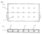
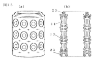
- the vacuum soundproof insulation body of the embodiment of FIG. 1 has an XX line cross section of (a) (b), has a layer for suppressing heat radiation and a getter in the main body, and supports the vacuum layer 13 with a magnetic force.
- a panel or a panel having a required number of support portions 11 facing each other, the peripheral edge of which is supported and sealed by a member 12 which supports and seals the peripheral edge of the facing outer packaging material, and the facing outer packaging material 14 has low radiation and gas barrier properties. Glass or the like may be used, and the arrangement and size of the support portion 11 are appropriate for supporting the vacuum layer 13, and if necessary, a size and arrangement with good light transmission and visibility, such as neodymium magnets and magnets with strong magnetic force, etc.
- the support portion 11 is made smaller by using an electromagnet, or the support portion 11 is subjected to a surface treatment that easily reflects, such as plating.
- the magnets may be arranged so that the axes of the repulsive force are slightly tilted in the directions of canceling each other so that the forces do not skid in the same direction all at once.
- the path of heat and sound propagation of the vacuum soundproof insulation body of the embodiment is (a) when the vacuum layer 13 is soundproofed, and the heat and sound are generated.
- the time of propagation is (b), and the opposite outer packaging material 14 in which the support portion 11 and the heat and sound path portion 27 are arranged opens and closes the heat and sound propagation path by manipulating the magnetic force of the support portion 11.
- the sealing 26 made of bellows, etc.
- the magnetic force of the support portion 11 is a magnetic field generator that does not use a coil such as a permanent magnet, a bond magnet, an electromagnet, or a magnetic semiconductor.
- the electromagnet may be a self-holding energy-saving type, and a magnetic field generator that does not use a coil such as a permanent magnet, a bond magnet, an electromagnet, or a magnetic semiconductor is a tertiary method such as collecting filaments or magnetic powder materials. It may be originally molded, and if necessary, it uses a material that is magnetized and electrically insulated, a material that conducts electricity, and a material that can be used as a semiconductor.
- Three-dimensional modeling is performed integrally with the outer packaging material 14 facing the sound path portion 27 and the sealing 26 made of bellows, etc. It may be electrically connected to an electromagnet embedded as a support portion 11, or a material having good heat conductivity may be used for the facing outer packaging material 14 to efficiently transfer heat, and the magnetic force of the support portion 11 can be obtained. It can be lost or operated, the direction and flow of the magnetic field lines may be changed by changing the position of the joint iron or magnet, the position of the joint iron or magnet may be changed manually, and power supply including wireless power supply is performed.
- the degree of vacuum may be improved by a cylinder or diaphragm that moves with the opening and closing of the heat path of the vacuum soundproof insulation, and a safety valve may be provided to prevent the degree of vacuum from becoming too high and causing destruction.
- a valve may be provided, or a pressure gauge may be provided.
- the vacuum soundproof insulation may insulate the heat including the cold heat stored in the cold insulation agent and / or the heat storage body, and when the heat is required, the heat path of the vacuum soundproof insulation is opened and closed and taken out.
- a vacuum soundproof insulation is placed next to the heat insulator and / or the heat storage body to store heat in the heat storage agent and / or the heat storage body, and when it is cold, the heat insulation agent is used.
- heat can be used for heating, hot water supply, plant cultivation, promotion of fermentation, thawing of frozen soil, thermoacoustic cooling, etc.
- cold heat can be used for cooling, storage of food, etc.
- the temperature difference can be used to operate the pump and Sterling engine, and the opening and closing of the heat and sound transmission path can be controlled by a program or learning function, or can be controlled according to the situation detected by a camera or sensor, and heat can be stored and used efficiently.
- the cold insulation agent and / or the heat storage body may be water, and heating and cooling and hot water supply can be performed, and the stored hot water can be used even when the water is cut off. FIG.
- the vacuum soundproof insulation body has a layer for suppressing heat radiation and a getter on the facing outer packaging material 14, and has a required number of magnetic support portions 11 facing each other to support the vacuum layer 13 with magnetic force.
- the support of the vacuum layer 13 is lost and the vacuum layer 13 is lost by changing the direction of the magnetic field lines, operating to eliminate the repulsive force of the support portion 11 with an electromagnet, or shifting the magnet to make the vacuum pulling force larger than the magnetic force.
- Heat and sound propagate when the opposing parts come into contact with each other, and by manipulating the action of the magnetic force of the support portion 11, thermal insulation and heat conduction can be switched arbitrarily, and the path for sound propagation as a soundproofing material.
- FIG. 4 is an example, in which examples of the YY line cross section of the perspective view (a) of the vacuum soundproof insulation body are (b), (c), and (d), respectively, using a material having gas barrier performance in space. By three-dimensionally modeling in the space of the required pressure including the space, the hollow part becomes a layer of the required pressure.
- the wall-like part 18 is laminated by three-dimensional modeling so that it is in contact with the peripheral edge, and the direction of the vacuum soundproof insulation during modeling is changed at the necessary stage to change the direction of gravity.
- the vacuum layer is formed airtightly by forming a vacuum layer up to the vicinity 21 of the required position while laminating on the lower portion 19, and the support portion 11 is necessary in the first example (b) of the YY line cross section.
- the required number of vacuum layers 13 are supported by the magnetic force of the support portion 11 so as to be embedded in the locations during modeling with the robot arm, and the vacuum layer 13 is provided with a layer that suppresses heat radiation, a getter, and a joint iron 22.
- the second example (c) of the YY line cross section is not necessarily if it can withstand pressure by being supported by the lattice structure 16, the structure used to make the bridge, or the partial connection between the exteriors in the vacuum layer.
- the vacuum layer 13 does not have to be supported by the magnetic force of the support portion 11, and may be shaped to withstand the pressure obtained by obtaining the strength by the ribs, structural analysis by a computer, or simulated, and is the third example of the YY line cross section ( In d), the periphery of the vacuum layer 13 is first three-dimensionally shaped and then wrapped in a three-dimensionally shaped lattice structure 16 in a space that has turned to high pressure.
- the strength of the high-pressure lattice structure 16 keeps the hollow layer, and the advantage of the vacuum soundproof insulation manufactured by three-dimensional molding is that the conventional core material is covered with a plastic laminate film outer cover to reduce the pressure. It improves the reliability of sealing of the heat insulating material to be sealed and the heat insulating property of the sealed part, and the production of the vacuum soundproof heat insulating body includes the robot arm and spraying in addition to the usual method of manufacturing the vacuum heat insulating material. Multiple printing methods, multiple printing material outlets, immersion materials, vessels, spaces where pressure, temperature and humidity can be changed, and objects that are three-dimensionally modeled for each three-dimensional modeling device or during three-dimensional modeling.
- a filament with gas barrier performance in a vacuum soundproof insulation machine that has at least one of the functions that can change the direction, reduce the influence of gravity and centrifugal force, and magnetize. Any of powdered or granulated aerogel or carbon, magnetic material, metal material, heat storage material, light-transmitting material, etc. Manufactured by using one or more to immerse the three-dimensional molding and / or core material in a dipping material that has gas barrier performance and can suppress heat radiation.
- FIG. 5 shows an example in a state in which the vacuum soundproof insulation body and the cold insulation agent and / or the heat storage body 28 are adjacent to each other, and the heat including the cold heat stored in the cold insulation agent and / or the heat storage body 28 is passed through the vacuum soundproof heat insulation body.
- the cold insulation agent and / or the heat storage body 28 functions as a device that can take out the heat including the cold heat stored in the cold insulation agent and / or the heat storage body 28 from the openable and closable heat and sound path of the vacuum soundproof insulation body, and the cold insulation agent and / or the heat storage body 28
- a heat storage material suitable for the usage situation such as stone, mortar, latent heat storage material, or individual phase change material may be used.
- the cold insulating agent and / or the heat storage body 28 may be water in a water tank, and the outer packaging material 14 facing the vacuum layer 13 may be a transparent material such as glass.
- FIG. 6 is a diagram for explaining that the vacuum soundproofing and insulating body reduces noise and the like, and FIG.
- FIG. 6 is a diagram schematically showing noise on one side of the outer packaging material 14 facing the vacuum layer 13 and sandwiching the vacuum layer 13. It arrives and is transmitted as the sealing 26 made of bellows, etc., the magnetic force of the mounting part 25, the support part 11, etc.
- the support portion 11 is a combination of a permanent magnet, an electromagnet, a piezoelectric element, or the like, and the vacuum layers are sandwiched between them, the vacuum soundproofing and insulating body can generate sound from the structure.
- the vacuum soundproof insulation can convert electricity into sound, it can work like a microphone and a speaker, and it is a schematic representation of the sound generated to cancel the reversed phase obtained in the electronic circuit.
- the vacuum soundproofing insulation may be made soundproof by issuing 33 to reduce the canceling noise level, and if the function of canceling the noise and soundproofing is prioritized, the degree of vacuum of the vacuum layer 13 may be low and there is no pressure difference. It may be a layer, such as the spring constant of the sealing 26 made of a bellows, mechanical elements such as sound propagation due to the hardness of the material, and not only external noise but also indoors such as piano practice. Learn various factors such as the sound from the inside to the outside, the time zone when the sound is coming out, the sound quality, the situation, etc. so that the sound of the vacuum does not leak to the neighborhood and cause annoyance, and make a comprehensive autonomous judgment by calculation.
- the soundproofing performance of the vacuum soundproofing and insulating body may be improved by predicting or digitally controlling.
- the vacuum soundproof insulation body is a seal made of a bellows or the like that seals the vacuum layer when an impact such as a gust of wind, a scattered object due to the gust of wind, or a baseball ball hits the vacuum layer and reaches one side of the opposing outer packaging materials.
- the support part is a magnet
- the magnetic force of the magnet works like a spring.
- the sound insulation wall is soundproofed and insulated with a lightweight vacuum soundproof insulation body as a member of the sound insulation wall.
- the heat of the water drives the heat pump to create water vapor and send it to the hollow area.
- the intake valve is opened, and the negative pressure takes in water again from the water pond, river, rainwater tank, etc., warms the water with the sun and surrounding heat, and operates the heat pump, but the water is a heat storage body.
- FIG. 7 shows an example, in which the vacuum soundproof insulation body is integrally formed with a vacuum layer hollow by three-dimensional modeling in a vacuum or depressurized space (a), and the support portion 11 is vacuum soundproofed during the three-dimensional modeling.
- a robot arm provided in a machine for manufacturing a heat insulating body, embedded in an outer packaging material during three-dimensional modeling, placed in a normal pressure space (b) such as atmospheric pressure, which is a space to be used, and is placed in a vacuum layer 13 It is manufactured based on 3D data calculated so that the shape of the vacuum soundproof heat insulating body and the working distance of the magnetic force of the opposing support portions 11 are optimized when the vacuum soundproofing heat insulating body is pulled by the air and pushed by the atmospheric pressure.
- b normal pressure space
- FIG. 8 shows an example, in which the space for three-dimensional modeling of the vacuum soundproof insulation is first depressurized to a vacuum state, and after the peripheral edge of the vacuum layer is printed so that the vacuum layer 13 is formed, the space for printing is depressurized.
- the vacuum layer 13 expands more than when the pressure area 29 group is printed, but the vacuum layer 13 shrinks more than when the vacuum layer 13 is printed.
- the pressure regions 29 groups swell, they push against each other and warp on the vacuum layer side, and the warping force works to prevent the vacuum soundproof insulation from losing pressure or acts as an auxiliary, and also acts on the vacuum layer 13.
- the 29 groups of pressure areas support each other so that the stones in the arch part of the stone arch bridge support each other and withstand the pressure, and the vacuum soundproof insulation is structurally used as a building material such as a wall.
- a vacuum region 23 and a pressure region 29 are provided in the vicinity of the joints, and the vacuum region 23 and the pressurization region are provided.
- the vacuum in the vacuum area 23 breaks and leaks, the surroundings pulled by the vacuum swell, and the pressure in the pressure area 29 is released. Shrinks, sandwiches the bulging joint where the vacuum of the adjacent vacuum soundproof insulation is broken, the vacuum soundproof insulation fits tightly, and penetrates through the vacuum area 23 and the pressure area 29 during construction. It may be fixed to a pillar or the like.
- a vacuum region provided inside a joint such as a protrusion of a block play block, which is a fitting joint between vacuum soundproof insulation bodies manufactured in a form of being fitted and stacked like a block play, is shot through.
- the vacuum in the vacuum area breaks and leaks, the surroundings that were pulled by the vacuum swell, the vacuum soundproof insulation bodies fit tightly together, and the vacuum at the joint is released.
- It may be equipped with a valve that can be evacuated and evacuated again to shrink the perimeter of the joint and evacuate. It can be made into a complicated shape by three-dimensional modeling, and it can be made into the shape of a tub with a vacuum layer, the cabin of a vehicle, the shape of a double-structured container that enhances heat retention, or the shape that can fill the space, and can be joined.
- a vacuum soundproof insulation body having a function of opening and closing a heat path collects heat including cold heat and stores it in a cold insulator and / or a heat storage body to insulate it, and heat of the vacuum soundproof insulation body when necessary. Heat is taken out from the path and used, but the surface area is increased to make it easier to collect heat and dissipate heat when taking out heat.
- Artificial diamond may be mixed to increase heat conduction, and by providing a layer that suppresses heat radiation, heat radiation may be suppressed during heat insulation, and heat may be radiated from the heat-conducting warm outer packaging material when heat is taken out.
- the structure may be such that light is repeatedly reflected and absorbed to generate heat, and if the manufacturing method is three-dimensional modeling, the surface area is larger than that of the machined heat collecting and radiating part, and the heat can be collected and radiated more.
- FIG. 10 shows an example.
- the second hollow layer is provided on both sides of the first hollow layer, which is the vacuum layer 13, and the third hollow layer is outside the second hollow layer when viewed from the first hollow layer.
- the second hollow layer and the third hollow layer are integrally formed in a certain shape and are arranged by a robot arm provided in the three-dimensional modeling device, or are connected by a pump 24 which is three-dimensionally formed.
- FIG. 11 shows an embodiment, in which the vacuum soundproof insulation body shaped like an envelope with a gusset has facing outer packagings so that the facing outer packaging materials 14 are pulled by the vacuum layer 13 and come into contact with each other so that heat and sound do not pass through.
- a portion 15 connected and pulled in the vacuum layer 13 provided on the member 12 for supporting and sealing the peripheral edge of the material holds the facing outer packaging material 14 so as to bulge slightly outward, and the portion 15 connected and pulled is, for example, a wire.
- a tube made of rope or carbon or a nylon zile may be used for strength, or a vacuum may be passed through the inside of the connecting and pulling portion 15, and the vacuum may be connected when pressure is applied to the passed fluid. If the pulling part 15 is made of a swelling material, connect it and wind the required number of non-stretchable fibers around the pulling part 15 as many times as necessary.
- the part 15 to be pulled works like an artificial muscle and moves to shrink, but the same mechanism may be used to prevent the opposing outer packaging materials 14 from being pulled by the vacuum layer 13 and coming into contact with each other.
- the base of the part 15 may be pulled by a magnetic force, or the base of the part 15 to be connected and pulled may be mechanically pulled by an actuator such as hydraulic or piezo.
- an actuator such as hydraulic or piezo.
- the point of action of the part 15 to be pulled may be pulled by a manual lever having fulcrums distributed on both sides of the line on which the force applied to the vacuum layer 13 is applied, and the pressure of the fluid is eliminated inside the part 15 to be connected and pulled.
- the manual lever is moved. When it is moved, that is, when it has a loosening function corresponding to each pulling function, the opposing outer packaging materials 14 pulled by the vacuum layer 13 are connected to each other and touch the pulling portion 15 as if sandwiching, and heat and sound pass through.
- the facing outer packaging material 14 may be a solar cell panel, glass, or transparent plastic, or may be used as a solar heat collector by passing water through the inside of the connecting and pulling portion 15, and may be used as a solar heat collector.
- the vacuum soundproof insulation bodies may be connected to each other, and the connection may engage the groove portion of the subsequent vacuum soundproof insulation body with the protruding portion and conduct the connection at the time of connection, and the vacuum region near the connected portion may be connected. If 23 was pierced with a screw or the like, the vacuum leaked and was drawn into the vacuum. If the periphery is bulged and the connecting portion is fitted and the fluid is passed through the pulling portion 15, the entire circumference of the seam of the flow path may be inflated and joined without omission.
- the vacuum soundproof insulation may be made of a material derived from a natural material such as bamboo, or may be made porous by carbonizing bamboo or the like to improve strength and heat insulation, and gelatin, agar, cellulose, corn, or starch may be used. It may be made to have biodecomposition performance by using protein, hemp, Japanese paper, etc., and it is three-dimensionally shaped with a vacuum soundproof insulation machine using raw materials such as ⁇ ⁇ , tofu and agar, and frozen with a temperature control function to remove moisture. You can obtain the core material of a vacuum soundproof insulation with a perforated hole and coat the surroundings with a printing material such as gelatin, cellulose, or cone so that it has a gas barrier property.
- FIG. 12 shows an example, and the vacuum soundproof insulation body manufactured by three-dimensional modeling has a hollow area for moving the joint iron 22 by pressure in addition to the vacuum layer 13 for thermal control and / or soundproofing.
- the tips of the valves 30 are overlapped so that their hands are aligned, and the joint iron 22 and the support portion 11 with magnetic force are printed by arrangement by a robot arm or by three-dimensional modeling, and are vacuum.
- the vacuum layer 13 was first airtightly printed in the space, and was printed to the vicinity of the valve 30 in a space where the pressure turned to an appropriate pressure to print the hollow area for moving the joint iron 22 by pressure, and then turned to high pressure.
- the pressure area 29 which is a part that bulges in order to bring the gaps between the tips of the valves 30 at the base of the valve 30 into close contact with each other in the space, the flow paths between the tips of the valves 30 are barely touched. It is printed with a gap, and when it receives a force in the space where the pressure is changed to the proper pressure again, the part 34 and the flow path whose volume changes are integrally and airtightly formed, and the pressure at the base of the valve 30 printed in the high pressure space is applied.
- the path of heat and sound propagation of the vacuum soundproof insulation body of the embodiment is (a) when the vacuum layer 13 is soundproofed and heat-insulated, and heat and sound propagate.
- the time is (b), and when the opposite outer packaging material 14 is moved sideways, the magnetic force is released and the vacuum is drawn to the vacuum, and the heat and sound propagation paths come into contact.
- the member 12 that can open and close the path of sound propagation and supports and seals the peripheral edge of the facing outer packaging material flexibly bends at the base to the lateral shift movement, but does not lose to the pulling force of the vacuum layer 13, for example, support. Even if the portion 11 has no magnetic force and cannot support the vacuum layer 13, it is deformed so as to tilt the parallel quadrilateral, and the member 12 that supports and seals the peripheral edge of the facing outer packaging material hits the opposite outer packaging material 14 and stops.
- the vacuum layer 13 cannot be displaced sideways, the gap between the vacuum layers 13 sandwiched between the facing outer packaging materials 14 cannot be narrowed, and the vacuum layer 13 can be held even if the support portion 11 has no magnetic force (a), in the opposite direction. When it is laterally displaced, it shifts to the point where the heat and sound propagation paths come into contact (b), and the vacuum soundproof insulation acts as an switch for the heat and sound propagation path using the force drawn by the vacuum, and is the opposite outer packaging material.
- the surface whose diagonal length changes due to deformation such as tilting the parallel quadrilateral of the member 12 that supports and seals the peripheral edge of the cloth is the same as the surface where the cloth has little expansion and contraction in the direction of the warp and weft, but is easy to move diagonally.
- each of (a), (b), and (c) is a top view of a rotary discharge port for propelling a vehicle for a water area, and shows the direction of a partition and the discharged water.
- the direction and momentum are schematically represented.
- the vehicle advances in the direction of 3 o'clock
- (b) advances in the direction of 9 o'clock
- (c) ejects in the direction of 7:30.
- the vehicle While rotating clockwise, the vehicle rotates faster by changing the ejection port with a strong force according to the rotation, and the vehicle is underwater as if the blades of the fan were lying down on the surface of the water. It is shaped to dive into the water and can move from the surface of the water to the water by diving into the water as it rotates, and can ascend by turning the spout with a strong force counterclockwise.
- FIG. 15 is an example, which is a vacuum soundproof insulation body manufactured in the shape of a cylinder by three-dimensional modeling. The inside and outside of the cylinder can be insulated, and the vacuum soundproof insulation bodies can be continuously connected and stretched.
- connection can be made by fitting the protruding part into the grooved part of the vacuum soundproof insulation that follows, and then piercing the vacuum area 23 near the fitting connection part with a screw or the like, so that the vacuum leaks and is pulled into the vacuum.
- the peripheral part that had been bulging and fitted is fitted with airtightness and structural strength, and is provided with a support portion 11 that faces the vacuum layer 13 and supports the vacuum layer 13, and the support portion 11 is provided with magnetic force and magnetic field lines. If it is equipped with a function that can open and close the path of heat and sound propagation by manipulating the path, heat and sound can be exchanged between the inside and outside of the cylinder.
- the vacuum soundproof insulation can be manufactured by three-dimensionally shaping it into a complicated shape, it can be manufactured into a cylinder or a sphere with a space inside, and a structure that can withstand the pressure difference between the vacuum layer and the atmospheric pressure.
- Airgel may be made from seaweed-derived raw materials and has gas barrier properties. By making a certain coating into weather-resistant and durable engineering plastic or recycled plastic, it is possible to compensate for the fact that naturally derived airgel is easily decomposed, and at the time of disposal, it can be roughly cut with a cutting machine and then washed away with water pressure to separate and collect the seaweed-derived airgel. Since the washed-out airgel derived from seaweed is biodegradable, it is unlikely to cause microplastic problems even if it leaks out, from collecting seaweed on a mega float to manufacturing airgel and vacuum soundproof insulation using airgel as a material. May be done. FIG.
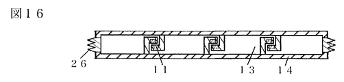
- FIG. 16 shows an embodiment, in which the support portion 11 is connected to the outer packaging material 14 facing each other by a support column, and the facing support portions 11 are attracted to each other to widen the space between the facing outer packaging materials 14 and hold the vacuum layer 13.
- the peripheral edge is supported by a sealing 26 made of a bellows or the like and airtightly sealed, and the path of heat and sound propagation can be opened and closed by manipulating the magnetic force of the supporting portion 11.
- a vacuum soundproof insulation body is used to take in heat including cold heat and store it in a cold insulator and / or a heat storage body, and the stored heat including cold heat is used as it is, or a heat pump is operated with heat including cold heat or a Stirling refrigerator.
- Stirling refrigerators such as Gifford McMahon refrigerators and pulse tube refrigerators, or cool electric wires, computers, superconducting materials, etc. by thermoacoustic cooling or magnetic refrigeration, and operate heat pumps or Stirling refrigerators. It is moved or thermo-acoustic cooled to exchange heat with the surroundings, and stores heat including cold heat to the amount that the chiller and / or heat storage body can store or exchange heat, for example, new heat storage and radiation when the temperature rises. When new cold heat can be expected to be stored in the cooling If sufficient heat energy is stored in the heat storage body and / or the chilling agent, it can be converted to another energy such as compressed air, electric power, or position energy by a Stirling engine or the like.
- a vacuum soundproof insulation and chiller and / or a vacuum soundproof insulation and / or a cooling agent that autonomously judge making water or boiling water based on weather forecasts, past climates, and learning, and learning about the surrounding climate and user usage. It is desirable that the system that combines the heat storage body and the Stirling engine be equipped with a backup power supply so that the accumulation of learning is not lost due to a power failure in an emergency or disaster, and to improve the degree of environmental contribution based on learning. It would be nice to have a control panel with visualization of energy saving and a function to inform the user of the electricity cost saved by voice and CO2 saved, and the heat including cold heat from the temperature difference of the universe using the vacuum soundproof insulation.
- the Stirling engine may be inferior to other powers in terms of power used for movement, but it is powered by a system that combines a vacuum soundproof insulation and an ice pack and / or a heat storage body and a Stirling engine. It is easy to use the power of the Stirling engine for movement in places where there is little gravity or where buoyancy works when moving the body.
- heat is collected by a solar heat collector, a device capable of condensing and converting light into heat, or a method of wrapping with aerogel, or cold heat is also included by a heat pump, a heat collector, heat exchange, radiant cooling, a sterling refrigerator, or the like. It collects heat and stores it in a cold insulator and / or a heat storage body to insulate it with a vacuum soundproof insulation body, and when heat is needed, the vacuum soundproof insulation body opens and closes the heat path and takes it out for use, but when the roof is covered with snow The collected heat may be returned to the solar heat collector to melt the snow.
- the heat insulation of the solar heat collector can be passed and the snow can be melted, and the snow cover on the roof is removed again.
- You can collect heat you can use the temperature difference between the cold heat of snow and the surroundings and the heat collected by the solar heat collector, you can safely remove the snow from the roof at any time without labor, and you can operate it remotely while looking at the camera etc. can.
- a vacuum soundproof insulation body is used, and the ice pack and / or the heat including the cold heat stored in the heat storage body is used for direct cooling, the thermoacoustic cooling, or the heat including the cold heat stored in the cold insulation agent and / or the heat storage body.
- the sterling refrigerator, heat pump, and magnetic refrigeration system are operated with the power that can be used to condense the moisture in the gas, and water can be obtained at the time of water outage, on the sea, on islands, in the desert, or where water needs to be obtained.
- the heat including the cold heat stored in the ice pack and / or the heat storage body may be used directly or by operating the heat pump to evaporate the seawater to obtain water and salt, and the generated steam may be used.
- thermoacoustic cooling generate power with thermoelectric materials
- steam engine and sterling engine Power is used to generate power, pump water, heat pumps, compress air, create pressure including vacuum used in the manufacture of vacuum soundproof insulation, and move objects in the opposite direction of gravity and centrifugal force.
- the machine that can be used for manufacturing and used for manufacturing vacuum soundproof insulation in 3D modeling may be a large machine such as an overhead crane, and the part where the printing material for 3D modeling comes out can be changed in height and moved vertically and horizontally. For example, if a vacuum soundproof insulation body having a hollow layer is manufactured by three-dimensional modeling in space, the hollow layer becomes a vacuum layer even if the machine does not have a vacuum chamber.
- a vacuum soundproof insulation body is used to expand and contract the gas with the heat stored in the heat storage body in a warm current or hot area or time and the cold heat stored in the cold insulation agent in a cold time or area and / or deep water to operate the pump.
- Moving objects such as mega floats, ships, drones and vehicles for water areas that move the obtained water flow and sterling engine with the power that can be moved are in favorable conditions in the inclination of the ground axis and changes in the climate so that heat including cold heat can be easily stored. You can go to the destination while visiting the place with information, observation and calculation, the temperature of other mega floats, ships, floating objects, drones and vehicles for water areas and the environment, the presence or absence of obstacles in the course, the surrounding terrain, etc.
- Information such as the flow of water and the situation of ships navigating in the vicinity may be shared and cooperated, and a moving body that moves on or under water that is anchored to a place where there is a flow uses the flow to screw or pump.
- the heat including the cold heat collected by moving the heat pump by moving the water wheel and the water wheel is taken in by the vacuum soundproof insulation and stored in the cold insulation agent and / or the heat storage body, and the moving body moving on or under the water is moved.
- water may be used as a cold insulating agent and / or a heat storage body, and by replacing the cold storage agent and / or water as a heat storage body in a water area having an appropriate temperature, heat including the necessary cold heat can be quickly obtained.
- the mega float opens the weir and takes in water, it sprays a small amount of vegetable oil or algae oil from the water with compressed air into the water taken in.
- the microplastic may be adsorbed on the oil and floated by the specific gravity of the oil and drawn into the area where the dust of the mega float in the dam is collected together with the water.
- Microplastics may be adsorbed on the oil by aeration by spraying the vegetable oil or algae oil, and the compressed air may be collected by filtering with a film. It is good to store it in a heat storage body and use the heat including the stored cold heat to obtain it with the power of moving a pump or Stirling engine.
- metals dissolved in water such as lithium and uranium are adsorbed and recovered by mixing fibers made from the recovered microplastics with an adsorbent. You may build a windmill on a megafloat or a nearby floating object, operate a heat pump with wind power to store and use heat, create compressed air with wind power, and use the internal space of the megafloat as an air tank for compressed air.
- cotton candy, rock wool, or glass fiber is made from plastic, glass, or stone material melted at high temperature from the discharge port of three-dimensional modeling printing material of a vacuum soundproof insulation body manufacturing machine equipped with a robot arm.
- a string-like or porous material formed in the same way, or a material containing a large amount of gas under normal pressure or pressure is discharged from the discharge port into a foamed shape so that the material creates bubbles in a vacuumed or depressurized manufacturing space.
- a vacuum or depressurized manufacturing space apply plastic, glass, or stone material melted at high temperature to the formed material by spraying it from the discharge port under normal pressure or pressurization, or by dropping it from the discharge port.
- the surface of melted vinyl, plastic, glass, or stone is formed by coating it so that it has a gas barrier property, or by forming it in a stringy, porous, or foaming shape, such as a candy whose surface is coated with chocolate.
- a vacuum soundproof insulation can be obtained by immersing it so that it is covered with the material for soaking in the glass, or by melting only the surface of what is formed in a stringy, porous or foaming shape so that it has a gas barrier property. Separability and recyclability may be improved by changing to different states such as string-like and candy-like and manufacturing integrally, and transparent glass, plastic, etc. can be used as a printing material for three-dimensional modeling by using a substance that changes color depending on temperature.
- transparent materials can also be sintered and melted with a laser or electron beam, and if necessary, substances that change color depending on the temperature may be evaporated so that the color does not return at low temperatures.
- the degree to which the melted filament or material is affected by gravity or centrifugal force is at least to the extent that it does not interfere with the function of the vacuum soundproof insulation, and at least the residue in printing does not interfere with the function of the vacuum sound insulation. It is good to make three-dimensional modeling while changing the direction for the purpose of leaving only If equipped, it is good to give the vacuum soundproof insulation manufacturing machine one or more functions such as using magnetic force, floating using air pressure to change the direction, and changing the direction of the work table.
- the vacuum soundproof insulation is manufactured in consideration of the direction of stacking, but in order to reduce the influence of gravity and centrifugal force on the melted filaments and materials, control the temperature of the manufacturing space or print three-dimensional modeling.
- it is equipped with a moving axis that can move by the required speed and amount, or by applying the mechanism of a linear motor car or elevator to move the entire manufacturing machine, a vacuum during three-dimensional modeling.
- the manufacturing machine can detect, calculate, control and reduce the effects of gravity and centrifugal force on the material with a camera or sensor, and the manufacturing space of the vacuum soundproof insulation can be surrounded by the vacuum soundproof insulation to provide sound insulation.
- Heat including cold heat can be dissipated from the heat and sound path of the body, and if necessary, a cold insulator and / or a heat storage body can be used as a heat exchanger, or a heat pump or the like can be used as a heat source for heat including cold heat to control the temperature of the manufacturing space.
- humidity adjustment including drying can be performed, layer-to-layer fusion can be controlled by preheating, and distortion that occurs when the vacuum soundproof insulation is three-dimensionally formed by controlling the temperature of the manufacturing space can be reduced, and the three-dimensionally formed vacuum. Residual strain can be reduced by putting the soundproof insulation in a box-shaped vacuum soundproof insulation and cooling it slowly, and the vacuum sound insulation can be three-dimensionally shaped in a vacuum space including space or a vacuum space and a function to give vibration.
- the three-dimensional modeling of the vacuum soundproof and heat insulating body does not necessarily have to be the FDM method, and may be any method such as an optical modeling method, an inkjet method, a powder method, or any method that can be reasonably formed.
- the optical modeling method In the case of three-dimensional modeling of a vacuum soundproof insulation with a hollow structure, pull up the vacuum soundproof insulation during printing from the surface filled with UV resin once before forming it in a sealed manner, and remove the resin inside.
- the temperature may be controlled so that the resin can be easily removed, and the vacuum soundproof insulation during printing may be moved or vibrated so that the resin can be easily removed.
- the uncured UV resin may be washed off by equipping the robot arm with a function that applies the mechanism of the dishwasher or a high-pressure washing machine.
- the vacuum soundproof insulation body manufactured by three-dimensional modeling can be made into a complicated shape and the dimensions etc. can be easily adjusted. Vacuum sound insulation can be made according to the building, as well as vacuum sound insulation in the shape of shoes and soles that are comfortable in size, shape and hardness for the feet according to individual differences in weight, foot length and width depending on the person.
- the body can be modeled three-dimensionally by giving the necessary numerical values to the manufacturing machine, the hollow layer also acts as a cushion from the structure, and if it also has the function of opening and closing the heat path, heat can be dissipated when the temperature inside the shoes rises, and bicycles and If you print on the shape of the seat of a chair etc., the hollow layer will be a vacuum soundproof insulation that keeps the bottom at a comfortable temperature and the hollow layer also acts as a cushion.
- the position, volume, and internal pressure can be calculated by calculation to print something suitable for the individual, and if it also has a function to open and close the heat path, heat can be dissipated when the temperature of the seat surface rises.
- the magnetic force of the support part that supports the vacuum layer loses to the weight when seated, and the heat of the heat storage body is passed through. If the butt becomes warm and the power supply is wireless, the waterproofness and cleanability will be good, and it may be manufactured as a cover for a heated toilet seat that does not have a heat source or power supply part and does not conduct heat except when sitting, and forgets to lower the toilet seat cover. Even in this case, power can be saved, and switching between heat insulation and heat transfer by weight may be performed by a method other than magnetic force.
- the elastic body is so hard that it cannot support the vacuum layer, or if the vacuum layer is heated by the weight of the vacuum soundproof insulation as shown in FIG. 8, the same effect can be obtained.
- It may be a method that can open and close the heat path arbitrarily like a heat insulator, and it can be used as a seat or bedding for vehicles and tools other than the toilet seat. It is portable and can be used as a cushion that warms when you sit or hold it, or as a device that warms your feet like a footbath only when you put your feet on it, or you can use it like a hot water tank. It can be used as a cold pillow, a cushion to cool off, an ice bag, a seat for vehicles and tools, and bedding.
- the vacuum soundproof insulation can be worn on a rucksack, vest, or something to wear on the head, and may be combined with a cold insulator and / or a heat storage body and a heat source of heat including cold heat to obtain an appropriate temperature.
- a three-dimensionally shaped vehicle occupant room-shaped vacuum soundproof insulation keeps the occupant room at a comfortable temperature with less energy, for example, in the case of a three-wheeled vehicle, it is integrally rooted from the occupant room to the front.
- both arms There are two arms with the first joint of the bellows that moves up and down, both arms have the second joint of the bellows that moves up and down in the middle, and the joint that becomes the steering of the bellows that moves left and right is at the tip of both arms.
- Both arms are connected to a rope of the required strength that forms a ring that goes around the passenger compartment around the central axis after the first joint, and when the first joint of one arm goes up, the rope goes to the other.
- the first joint of the arm can be lowered, the vehicle body can be tilted in the turning direction, and the second and third joints are equipped with suspension devices.
- An elastic body that moves in the direction is arranged so as to cross both sides of the bellows of the second joint, and an elastic body that moves in the telescopic direction containing fluid is also arranged on both upper sides of the bellows of the first joint so as to cross the first joint.
- the elastic body of the left first joint and the elastic body of the second joint are connected by a flow path that intersects the left and right, and if it is tilted to the right, the left first joint bends downward and the elastic body of the left first joint is stretched and communicated by the flow path.
- the elastic body of the second joint is contracted and tilted to the left, the right first joint will bend downward, the elastic body of the first joint will be stretched, the elastic body of the second joint on the left side will be contracted, and the left and right steering joints will run.
- the second joint is a speed increaser and motor linked to movement, the weight of rotation is used as a damper, elastic body or fluid elasticity is used, the suspension device functions, the motor can generate power ,
- the steering device has a part where the steering turns to the left and right so that it crosses the joint of the steering, and there is a part where the volume changes by being pushed by the rack on the left and right of the rack.
- the right and left can be steered through the left and the flow path, and the flow path may be formed integrally with the arm.
- the doors such as the boarding gate, outside air intake, and luggage compartment that are in contact with each other are all integrally formed, and the wheels are lightweight because they are integrated and lightweight, and the passenger compartment is soundproofed and insulated, and the front and rear wheels, braking devices, and dampers.
- the soundproof insulation may be equipped with a heat storage material for the efficiency of the motor, the power may be electric assist and human power, and if the vehicle is used in a place with low gravity, the power may be a heat storage material and a sterling engine, and surplus kinetic energy. It may be equipped with a system that regenerates with a fly wheel that uses the weight of the storage battery, and the exchange of electricity between the rotating storage battery and the vehicle body may be done by a slip ring or a wireless electrically efficient one, and the vehicle body is the sun.
- vacuum soundproof insulation is required in all situations where energy saving is required, when energy is extracted from heat by applying the function of the vacuum sound insulation insulation, and in situations where sound insulation is required. It is good if the body can play an active role, manufacturing is automated and it may be made in large quantities at low cost. If soundproof insulation is actually used and information about its use is shared or fed back, it will be learned, simulated, improved and reflected in manufacturing to reduce stress concentration, improve earthquake resistance, and not only sound insulation.
- the material, structure, and function are approaching optimization, such as the shape that enhances sound absorption, and the fact that the vacuum soundproof insulation does not cause magnetic flux leakage or magnetic interference to the outside when magnetic is used for the support part. It is recommended to take in and refer to the heat flow inside the material and the structure information seen in the natural world such as plants and cells, and perform deep learning by artificial intelligence to further optimize.
- It can be used for heat management, utilization and soundproofing in various industries such as buildings, energy fields and vehicles.
- Support part 12 that supports and seals the peripheral edge of the facing outer packaging material 13 Vacuum layer 14 Opposing outer packaging material 15 Connecting and pulling part 16 Lattice structure 17 Floor-like part 18 Wall-like part 19 Change direction 21 Near the required position 22 Joint iron 23 Vacuum area 24 Pump 25 Mounting part 26 Sealing made of bellows 27 Heat and sound path part 28 Coolant and / or heat storage body 29 Pressurized area 30 Valve 31 Schematic representation of noise 32 Schematic representation of sound passing through a vacuum soundproof insulation 33 Schematic representation of sound generated to cancel 34 Volume change
Abstract
本発明は、真空防音断熱材において、真空層を保持する支持部の熱や音の伝播を減らす真空防音断熱体を提供すること、防音性能と熱管理性能が向上する機能を持たせた真空防音断熱体を提供すること、真空防音断熱体の製造方法を提供することを主目的とする。本発明は、真空防音断熱体において本体に、熱と音の伝播の少ない磁力を利用した支持部か、構造的に従来より熱と音の伝播を減らす支持部及び周縁部か、熱と音の伝播の経路の開閉機能を持たせた支持部のいずれか一つ以上を備え、従来よりも防音性や熱管理性能や利用範囲のいずれか一つ以上が増える真空防音断熱体を得られることと、真空防音断熱体を性能よく合理的に作るため圧力を考慮した空間で及び/又は三次元造形して製造することで目的を達成する。
Description
本発明は、真空防音断熱体およびその製造方法に関する。
住環境の保全等の観点で省エネルギー化や防音のニーズが高まり、真空断熱材や複層ガラスの高い断熱性能や防音性能が注目され、真空断熱材や複層ガラスは様々な熱や音の伝わりを減らす工夫がされ、建物などで利用されており、例えば特許文献1や特許文献2や特許文献3が知られる。
真空断熱材や複層ガラスにおいては、大気圧に負けずに真空層を保持する支持部である芯材やスペーサーを介して熱や音が伝播する課題があった。
真空断熱材や複層ガラスにおいては、大気圧に負けずに真空層を保持する支持部である芯材やスペーサーを介して熱や音が伝播する課題があった。
本発明は上述した従来の課題に鑑みてなされ、断熱層である真空層を支える支持部の熱や音の伝播を減らすこと及び/又は支持部に機能性を持たせることで防音性能と熱管理性能が向上し利用範囲の増える真空断熱材である真空防音断熱体の提供および真空防音断熱体の製造方法の提供を目的とする。
課題の解決手段を検討し、熱と音の伝播の少ない磁力を利用した支持部か、熱と音の伝播の減る構造の支持部か、熱と音の伝播の経路の開閉機能を持たせた支持部のいずれか一つ以上を備えると、従来より防音や熱管理や利用範囲に富む真空断熱材である真空防音断熱体を得ること、性能よく作るには圧力を考慮した空間で及び/又は三次元造形して製造する方法があること、を見出し本発明が完成した。
本発明によれば、真空層に熱や音を伝播する介在物を減らし熱と音の伝播経路を開閉でき防音性能や熱管理性能や省エネ性能良好で複雑な形状にも形成でき利用範囲の広い真空防音断熱体を得られる。
真空防音断熱体には従来の断熱材の機能と防音材の機能と熱と音の伝播の経路の開閉機能と音と衝撃を能動的に減らす機能があり、熱の経路の開閉の機能と蓄熱体を併用すれば熱の保管と利用ができる。
図1の実施例の真空防音断熱体は、(a)のX−X線断面が(b)であり、本体に熱放射を抑える層とゲッターを有し、真空層13を磁力で支えるのに必要な数の支持部11を対向に備え、対向する外包材の周縁を支持し封止する部材12により周縁を支持し封止され、対向する外包材14は低放射でガスバリア性を有するパネルやガラスなどで良く、支持部11の配置や大きさは真空層13を支持するのに適切で、必要があれば光の透過や視界性の良い大きさと配置で、ネオジム磁石や磁力が強い磁石や電磁石を用いて支持部11を小さくしたり支持部11にメッキなどの反射しやすい表面処理を施すが近傍にレンズやフレネルレンズを支持部11が小さく見えるよう配するか反射板の構造による反射や人工ダイヤモンドやガラスやプラスチックのカットと物性による反射と屈折などを利用し視覚的に目立ちにくくしても良く、真空防音断熱体はシリカエアロゲルなど光を通すものを使用して製造することや材料に透明性のあるフィラメントなどを使用して三次元造形して製造することで、視線や光などを透過することもでき、支持部11に磁力を発生させるものを用いるときは、磁力が十分に強力か適切で減磁が起きにくいものを減磁が起きにくい配置で使うと良く、ペースメーカーやシャント手術バルブの誤作動や電子機器など周囲への磁力の影響や、周囲の磁性体との磁力の影響の授受も考慮した大きさと配置と磁力であると望ましく、斥力はお互いを遠ざけようと振る舞うため中心から横にずれる方向にも力がかかり、複数の支持部11をそれぞれ打ち消し合う方向にわずかにずらすか斥力の軸をそれぞれ打ち消し合う方向にわずかに倒して力が一斉に同じ方向に横滑りしないように考慮した配置にしても良い。
図2の(a)と(b)は、実施例の真空防音断熱体の熱と音の伝播の経路が、真空層13で防音断熱されている時が(a)であり、熱と音が伝播する時が(b)であり、支持部11と熱と音の経路部27が配設された対向する外包材14は支持部11の磁力の操作によって熱と音の伝播の経路を開閉し、蛇腹などでできた封止26は必要な柔軟性と強度と気密性があり、支持部11の磁力は永久磁石や、ボンド磁石や、電磁石や、磁性半導体などコイルを用いない磁界発生器で得るが、電磁石は自己保持型の省エネタイプのものでも良く、永久磁石や、ボンド磁石や、電磁石や、磁性半導体などコイルを用いない磁界発生器はフィラメントや磁性粉末材料をまとめる等の方法で三次元造形されたものでも良く、必要に応じて着磁され、電気的に絶縁される材料、導通する材料、半導体として利用できる材料を使用し、例えば電気を供給する経路とワイヤレス給電部を、熱と音の経路部27と対向する外包材14と蛇腹などでできた封止26と一体に三次元造形し、真空防音断熱体の製造機に備えたロボットアームで三次元造形中の材料の中に支持部11として埋設した電磁石と電気的に接続しても良く、対向する外包材14に熱伝導の良い材料を用い熱の受け渡しを効率よく行っても良く、支持部11の磁力は得たり無くしたり操作でき、継鉄か磁石の位置を変えることで磁力線の向きや流れを変えて操作しても良く、継鉄か磁石の位置は手動で変えても良く、ワイヤレス給電も含む給電をして小型のモーターやピエゾアクチュエータを動かして継鉄か磁石の位置を変えても良く、真空防音断熱体に真空度維持の為にゲッターの他にポンプを動かす小型のモーターやピエゾアクチュエータを備えても良く、真空防音断熱体の熱の経路の開閉に伴い動くシリンダーやダイヤフラムで真空度を向上させても良く、真空度が高まりすぎて破壊が起きないよう安全弁を備えても良く、真空引き用の弁を備えても良く、圧力計を備えても良い。
実施例として、真空防音断熱体は保冷剤及び/又は蓄熱体に蓄えた冷熱も含む熱を、断熱しても良く、熱が必要な時に真空防音断熱体の熱の経路を開閉して取り出して利用するが、例えば寒暖の激しい宇宙や砂漠での利用では保冷剤及び/又は蓄熱体の隣に真空防音断熱体を配置して暑いとき保冷剤及び/又は蓄熱体に蓄熱し、寒いとき保冷剤及び/又は蓄熱体に冷熱を蓄え、熱は暖房や給湯や植物の栽培や発酵の促進や凍土の解凍や熱音響冷却などに使え、冷熱は冷房や食品の保存などに使え、熱と冷熱の温度差はポンプやスターリングエンジンを動かすのに使え、熱や音の伝達経路の開閉をプログラムや学習機能で制御したり、カメラやセンサーなどで検出した状況に応じ制御でき、熱を効率よく蓄え使用でき、保冷剤及び/又は蓄熱体は水でも良く冷暖房や給湯などが行え、断水時にも蓄えた湯水が使える。
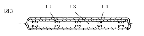
図3は実施例であり、真空防音断熱体は、対向する外包材14に熱放射を抑える層とゲッターを有し、磁力を有する支持部11を必要数対向に備え磁力で真空層13を支えており、磁力線の向きを変えるか、電磁石で支持部11の斥力を無くす操作をするか、磁石をずらし磁力より真空の引く力を大きくすることで、真空層13の支持が失われ真空層13をはさみ対向する部分が接触し熱と音が伝播し、支持部11の磁力の働きを操作をすることで、熱絶縁と熱伝導の切替が任意にでき、防音材としても音の伝播する経路を任意に開閉でき、周りをガスバリア性のある膜で気密に封止されるが、熱と音の経路の開閉の機能を優先するならば真空層13の真空度は低くても良く圧力差の無い中空層であっても良い。
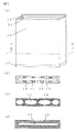
図4は実施例であり、真空防音断熱体の斜視図(a)のY−Y線断面の例がそれぞれ(b)(c)(d)であり、ガスバリア性能を備えた材料を用いて宇宙空間も含む必要な圧の空間で三次元造形することで中空の部分は必要な圧力の層になり、例えば初めに斜視図(a)に示す向きで見て底になる床の様な部分17を三次元造形し周縁に接するよう囲むかたちで壁の様な部分18を三次元造形で積層し、必要な段階で造形中の真空防音断熱体の向きを変えることで重力の働く向きを変え、向きを変えた後下になる部分19に積層しながら必要な位置の近傍21まで三次元造形し真空層を気密に形成し、Y−Y線断面の一例目(b)では支持部11は必要箇所に必要数をロボットアームで造形中に埋め込まれるように揺動なく対向に配置され、支持部11の磁力によって真空層13は支持され、熱放射を抑える層とゲッターと継鉄22を備えても良く、Y−Y線断面の2例目(c)はラティス構造16や橋を作るのに用いられる構造や真空層中での外装間の部分接続によって支持することで圧力に耐えるならば必ずしも真空層13は支持部11の磁力で支持されなくとも良く、リブによる強度の獲得やコンピューターによる構造解析や模擬で導いた圧力に耐える形にしても良く、Y−Y線断面の3例目(d)では、まず真空層13周縁を三次元造形したのち高圧に転じた空間で三次元造形したラティス構造16で包み、ラティス構造16の内部は高圧によって空気入りタイヤのように形を保ち、内部が高圧のラティス構造16の部分の強度で中空層を保つし、三次元造形で製造される真空防音断熱体の利点は、従来の芯材をプラスチックラミネートフィルム製の外被材で覆って減圧し封止する断熱材の封止の信頼性や、封止部分の断熱性を改善するし、真空防音断熱体の製造は通常の真空断熱材の製造方法の他に、ロボットアームと、吹き付けも含む複数の印刷方法と、複数の印刷材料吐出口と、浸け材料と、器と、圧力や温度や湿度を変えられる空間と、三次元造形装置ごとか三次元造形中に三次元造形される物の向きを変えることができる機能と、重力や遠心力の影響を減らせる機能と、着磁できる機能の少なくともいずれか一つ以上を備える真空防音断熱体の製造機でガスバリア性能を備えたフィラメントや、粉や粒にしたエアロゲルやカーボンや、磁性材料や、金属材料や、蓄熱材料や光を通す材料などのいずれか一つ以上を用いて三次元造形及び/又は芯材をガスバリア性能を備え熱放射を抑えられる浸け材料に浸す方法で製造される。
図5は実施例であり、真空防音断熱体と保冷剤及び/又は蓄熱体28が隣接し、保冷剤及び/又は蓄熱体28に蓄えた冷熱も含む熱を真空防音断熱体が通している状態であり、保冷剤及び/又は蓄熱体28が蓄える冷熱も含む熱を真空防音断熱体の開閉自在な熱と音の経路から必要な時に取り出せる装置として機能し、保冷剤及び/又は蓄熱体28は石やモルタルや潜熱蓄熱材や個体相変化材料など使用状況に適した蓄熱材料で良く、保冷剤及び/又は蓄熱体28は真空防音断熱体に内蔵されるか外包材を兼ねるか真空防音断熱体に囲まれる等の形で一体に製造されても良く、保冷剤及び/又は蓄熱体28は水槽に入った水でも良く真空層13を挟み対向する外包材14がガラスなど透明な素材ならば光を通す。
図6は実施例であり、真空防音断熱体が騒音などを減らすことを説明する図であり、騒音を模式的に表したもの31が真空層13を挟み対向する外包材14のうちの片側に届き、蛇腹などでできた封止26や取り付け部25や支持部11の磁力などを伝わり反対側の対向する外包材14から真空防音断熱体を通過した音を模式的に表したもの32として出てきて、例えば支持部11が永久磁石や電磁石や圧電素子などから必要なものを選択又は組み合わせたものであり、真空層を対向に挟む配置であればその構造から真空防音断熱体は音を電気に変換でき、また真空防音断熱体は電気を音に変換でき、マイクとスピーカーのように働かせることができ、電子回路で得た逆相にした打ち消すために生成した音を模式的に表したもの33を出して打ち消し騒音レベルを下げる方法で真空防音断熱体に防音をさせても良く、騒音を打ち消し防音する機能を優先するならば真空層13の真空度は低くても良く圧力差の無い中空層であっても良く、蛇腹などでできた封止26のバネ定数や、素材の硬さによる音の伝播などの機械的な要素や、外からの騒音だけでなく例えばピアノの練習などの室内の音が近所に漏れて迷惑とならないようになど内から外への音や、音の出ている時間帯や音質や状況など様々な要素を学習して算法で総合的に自律的に判断や予測させたりデジタル制御して真空防音断熱体の防音性能を向上させても良い。
実施例として、真空防音断熱体は突風や突風による飛散物や野球ボールがぶつかる等の衝撃が真空層を挟み対向する外包材のうちの片側に届き真空層を封止する蛇腹などでできた封止や取り付け部や支持部に伝わるとき支持部が磁石であれば磁石の磁力がバネのように働き例えば支持部が電磁石であればその構造から衝撃を電気に変換できサッカーでボールを受け取る時のトラップの動作のように衝撃エネルギーを電気に変換しながら検知し受け止めることで窓や建物などの破損を減らすことができ衝撃エネルギーを電気に変換する量を衝撃の強さや減衰の量などから計算しより能動的に衝撃エネルギーを吸収でき、風や豪雨や水域施設では波や濁流などの衝撃エネルギーから変換して電気を得て利用しても良い。
実施例として、遮音壁の部材としては軽量な真空防音断熱体で防音と断熱がされた遮音壁は壁の高さ近くまで水の入る域と中空域が内部にあり、太陽や周囲の熱を蓄えた水の熱でヒートポンプを動かし水蒸気を作り中空域に送り、中空域が高圧になったら弁から中空域の圧力と水の自重で湯になった水を排出し閉弁し中空域の水蒸気が冷え圧力が負圧に転じたら取り込み弁を開弁し、負圧で遊水池や河川や雨水タンクなどから再び水を取り込み太陽や周囲の熱で水を温めヒートポンプを動かすが、水は蓄熱体であるとともに防音のための質量でもあり、排出された湯は近隣の施設や家庭に送られセントラルヒーティングや床暖房等として使われて良く、排出圧の一部を発電に使っても良く、蓄電しても良く、得た電気で遮音壁の真空防音断熱体に能動的に防音をさせても良く、電気を電子看板や照明に用いても良い。
図7は実施例であり、真空防音断熱体は真空もしくは減圧された空間(a)で三次元造形により真空層を中空に一体に作られ、支持部11は三次元造形の最中に真空防音断熱体の製造のための機械に備えたロボットアームによって配置され三次元造形中の外包材に埋設され、使用する空間である大気圧等の常圧の空間(b)に置かれ、真空層13に引かれ、大気圧に押された時に、真空防音断熱体の形状と、対向する支持部11の磁力の働く距離が最適になるように計算された3Dデータに基づき製造される。
図8は実施例であり、真空防音断熱体の三次元造形を行う空間は始めに真空状態に減圧されていて真空層13ができるよう真空層周縁が印刷された後に、印刷を行う空間は減圧から加圧に転じ真空層13が印刷された時よりも加圧によって縮まった真空層13に引っ張られ縮まった真空層周縁に沿い必要数の加圧域29群ができるよう仕切りを作るように印刷することで、印刷終了後に移動した常圧の空間では、加圧域29群が印刷された時よりは真空層13が膨むが、真空層13が印刷された時よりは真空層13が縮まり、加圧域29群はそれぞれが膨らむことでお互いに押し合い真空層側に反りが生じ、反る力が真空防音断熱体が圧力に負けないように働くか補助的に働くとともに、真空層13に引っ張られ常圧にも押されながら加圧域29群が石のアーチ橋のアーチ部の石がお互いで支え合うように支え合い圧力に耐えるし、真空防音断熱体を壁などの建材として構造的な強度を持たせて使用したい場合に、隣り合う真空防音断熱体同士のはめ合い接合部を強固に接合するため接合部近傍に真空域23と加圧域29を設け真空域23と加圧域29を射抜くように隣り合う真空防音断熱体同士をネジなどで止めることで、真空域23は真空が破れ漏れて真空に引っ張られていた周囲が膨らみ、加圧域29は加圧が抜けることで縮み、隣りの真空防音断熱体の真空が破れて膨らんだ接合部を挟持し、真空防音断熱体同士は強固に嵌合するし、施工時は真空域23と加圧域29を射抜くように貫通し柱などに固定しても良い。
実施例として、ブロック遊びのようにはめ込み積み重ねる形に製造された真空防音断熱体同士のはめ合い接合部であるブロック遊びのブロックの突起のような接合部の内部に設けた真空域を射抜くように真空防音断熱体同士をビス等で繋ぎ止めることで真空域は真空が破れ漏れて真空に引っ張られていた周囲が膨らみ真空防音断熱体同士は強固に嵌合するし、接合部の真空を解放して嵌合でき再び真空引きし接合部の周囲を縮めて嵌合を外せる弁を備えても良く、真空防音断熱体は、いずれも減圧した中空のブロックやパネルや壁や天井や床の形にできるし、三次元造形すれば複雑な形にでき真空層をもった浴槽や乗り物のキャビンの形や保温性を高める二重構造容器の形や空間充填できる形にでき、接合できる。
図9は実施例であり、熱の経路の開閉の機能のある真空防音断熱体は冷熱も含む熱を集め保冷剤及び/又は蓄熱体に蓄え断熱し、必要な時に真空防音断熱体の熱の経路から熱を取り出し利用するが、表面積を増やして熱を集めやすく熱を取り出す時には放熱しやすくし、真空防音断熱体の材料に、セラミックや石質や炭素など熱放射を得られるものを混ぜたり、人工ダイヤモンドを混ぜ熱伝導を高めても良く、熱放射を抑える層も備えることで断熱時には熱放射を抑え、熱を取り出す時には熱伝導して温まった外包材から熱放射させても良く、細密な構造で光に反射と吸収を繰り返させ熱にしても良く、製造方法が三次元造形であれば機械加工の集放熱部よりも表面積が増え集放熱がより多くできる形にできる。
図10は実施例であり、真空防音断熱体は、真空層13である第1中空層の両側に第2中空層があり第1中空層からみて第2中空層の外側に第3中空層がある形に一体に三次元造形され、第2中空層と第3中空層は、三次元造形装置に備えたロボットアームで配設されたか、三次元造形された、ポンプ24でつながっていて、必要な圧に調整されていて、ポンプ24で内部流体が移動され第2中空層が縮むと第3中空層は膨らみ第1中空層側に反りが生じ、第1中空層はより広く開いて断熱と遮音がされている状態だが、第2中空層が膨らむと第3中空層は縮み第1中空層と反対側に反りが生じ、対向する第1中空層と第2中空層の隔たりが第1中空層にせり出してきて、対向する隔たり同士が触れ熱と音が通る。
図11は実施例であり、マチ付き封筒のような形状の真空防音断熱体は、対向する外包材14同士が真空層13に引かれて接触し熱や音が通らないように、対向する外包材の周縁を支持し封止する部材12に設けた真空層13内で接続して引く部分15で対向する外包材14がやや外に膨らむように保持し、接続して引く部分15は例えばワイヤーロープや炭素で構成されているチューブやナイロンザイルで強度を持たせても良く、接続して引く部分15の内部に流体を通しても良く、内部に通した流体に圧力をかけた場合に接続して引く部分15が膨らむ材質であるなら接続して引く部分15に必要な本数の伸びない繊維などを必要な回数巻きつけ引く部分15の端と繊維の端を接合して流体に圧力をかけると接続して引く部分15は人工筋肉のように働き縮む動きをするが同様の仕組みを利用して対向する外包材14同士が真空層13に引かれて接触しないようにしても良く、接続して引く部分15の付け根を磁力で引いても良く、接続して引く部分15の付け根を機械的に例えば油圧やピエゾ等のアクチュエータで引いても良く、時計を例にすると真空層13から12時が遠く6時が近くなるよう見て11時の位置にいる時に引かれている作用点が時計の中心を支点に12時を通り午後1時を通過して緩み始めるようにできるのと同様に、接続して引く部分15の作用点を真空層13に引かれる力のかかる線上の両側に振り分けられる支点を持つ手動レバーで引いても良く、接続して引く部分15の内部に流体の圧力をなくした時か、マグネットベース等のように磁力線の向きを変えた時か、電磁石の磁力をなくす操作をした時か、機械的に弛緩した時か、接続して引く部分15が緩む位置に手動レバーを動かした時に、つまりそれぞれの引く働きに対応する緩める働きをした時に、真空層13に引かれた対向する外包材14同士が接続して引く部分15をサンドイッチするように触れて熱や音が通るが、対向する外包材14は太陽電池パネルやガラスや透明なプラスチックでも良く、接続して引く部分15の内部に水を通し断熱し太陽熱集熱器として使っても良く、通熱し太陽電池を水冷しても良く、真空防音断熱体同士は接続でき、接続は突起部分を次に続く真空防音断熱体の溝部分に係合し、接続時に導通もしても良く、接続された部分近傍の真空域23をネジ等で貫き止めれば真空が漏れ真空に引かれていた周辺が膨らみ接続部分は嵌合し、引く部分15に流体を通すなら流路の継ぎ目全周を膨らませ漏れなく継合させても良い。
実施例として真空防音断熱体は竹などの天然素材由来の材料でできていても良く、竹などを炭化させ多孔にし強度と断熱性を向上させても良く、ゼラチンや寒天やセルロースやコーンやデンプンやタンパク質や麻や和紙などを用いて生分解性能を持たせても良く、材料に蒟蒻や豆腐や寒天の原料を用い真空防音断熱体製造機で三次元造形し温度調節機能で冷凍し水分を抜き多孔の真空防音断熱体の芯材部を得て周囲を一体にゼラチンやセルロースやコーンなどの印刷材料でガスバリア性のあるようにコーティングしても良く、食器などの形にもでき、食べることもでき、自然に還る、真空防音断熱体となる。
図12は実施例であり、三次元造形して製造する真空防音断熱体は熱管理及び/又は防音のための真空層13とは別に、圧力で継鉄22を移動させるための中空域があり、圧をかけると裏返って開閉方向が切り替わる弁30と、力を受けると変形し容積のかわる部分34が域内にあり、弁30は適度に柔軟な三次元造形の印刷材料で印刷され自動車のワイパーのような断面で、弁30の先端同士は手を合わせるように重なった形をしており、継鉄22や磁力を持つ支持部11はロボットアームによる配置か三次元造形で印刷され、真空の空間で真空層13が先に気密に印刷され、圧力で継鉄22を移動させるための中空域を印刷するのに適正な圧力に転じた空間で弁30の近傍まで印刷され、高圧に転じた空間で弁30の付け根にある弁30の先端同士の流路の隙間を密着させるために膨らむ部分である加圧域29を印刷されたのち弁30の先端同士の流路はかろうじて触れない程度の隙間を持って印刷され、再び適正な圧力に転じた空間で力を受けると容積のかわる部分34や流路を一体に気密に形成され、高圧の空間で印刷された弁30の付け根の加圧域29が常圧の空間で膨らむことで先端の隙間が密着し弁として機能するようになり、容積のかわる部分34が手で押すなど外部からの力を受けると圧力で継鉄22が動き、反対側の容積のかわる部分34が外部からの力を受けると圧力で継鉄22が元の位置に動き、磁力線の向きを変えて熱と音の経路を開閉できるが、製造方法は必ずしも三次元造形でなくて良い。
図13の(a)と(b)は実施例の真空防音断熱体の熱と音の伝播の経路が、真空層13で防音断熱されている時が(a)であり、熱と音が伝播する時が(b)であり、対向する外包材14を横にずらすと磁力が外れ真空に引かれて熱と音の伝播の経路が接触し、元の位置に戻せば防音断熱し、熱と音の伝播の経路を開閉でき、対向する外包材の周縁を支持し封止する部材12は横にずらす動きには付け根が柔軟に折れ応ずるが真空層13の引く力には負けず、例えば支持部11に磁力がなく真空層13を支持できなくても、平行四辺形を倒すように変形し、対向する外包材の周縁を支持し封止する部材12が対向する外包材14と当たり止まる所まで来て横にずれることができなくなれば対向する外包材14に挟まれた真空層13の隙間が狭くなれず支持部11に磁力がなくても真空層13が保持でき(a)、反対方向に横ずれさせた時には熱と音の伝播の経路が接触する所までずれ(b)、真空防音断熱体は真空が引く力を利用した熱と音の伝播の経路の開閉器となり、対向する外包材の周縁を支持し封止する部材12の平行四辺形を倒すような変形で対角線の長さが変わる面は布が縦糸や横糸の方向には伸縮が少ないのに対角線には動きやすいのと同じように強度のある格子となる部分に厚みを持たせながら格子の間を薄くし柔軟に気密に作ることで耐圧でありながら横ずれに対応できるし、柔軟性と強度の点で適切な一つの材料で作ることもでき、分別性とリサイクル性も良くなり、三次元造形して作ることもできる。
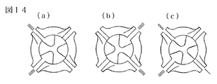
図14は実施例であり、(a)(b)(c)それぞれは水域用のビークルの推進のための、回転式の吐出口を上から見た図で、仕切りの向きと吐出する水の向きと勢いを模式的に表しており、(a)の位置の時にビークルは3時の方向に進み、(b)は9時の方向に進み、(c)は、7時半の方向に吐出する勢いの2/3の勢いを10時半の方向に吐出し7時半の方向に吐出する勢いの1/3の勢いを4時半の方向に吐出し、ビークルは1時の方向に進みながら時計回りに回転するが、回転に合わせて強い勢いで吐出する口を時計回りに変えていくことでビークルはより回転が早くなっていき、ビークルは扇風機の羽根を水面に伏せたように水中に潜る形になっていて回転とともに水中に潜ることで水面から水中へと移動でき、強い勢いで吐出する口を反時計周りにすれば浮上できるが、ビークルの概略構成は例えば、回転式の吐出口と重なり合い180度反転した同じ形状の回転式の吸い込み口があり、その積層方向両外側に向かって順に膜、真空防音断熱体、保冷剤及び/又は蓄熱体があり冷熱も含む熱を利用して気体を膨張収縮させ幕を動かし水を吸い込み吐出し水域用のビークルは移動し、遠隔操作でき、カメラや通信手段を有し水域の地形や水の流れや温度や周囲の状況などを発信するが、水中に潜ってプラスチックゴミを発見し、ゴミを集めて処理場に運ぶ回収船にゴミの量や種類のわかる画像や位置情報等を送信できる。
図15は実施例であり、三次元造形で筒の形に製造された真空防音断熱体であり、筒の内側と外側を断熱でき、真空防音断熱体同士を連続して接続して伸ばすことができ、接続は出っ張った部分を次に続く真空防音断熱体の溝になった部分にはめ込んだ後、はめ込み接続部分近傍の真空域23をネジなどで貫き止めることで真空が漏れて真空に引っ張られていた周辺が膨らみはめ込み接続部分は気密性と構造的な強度を持って嵌合し、真空層13を挟んで対向し真空層13を支持する支持部11を備え、支持部11に磁力や磁力線の通り道を操作して熱と音の伝播の経路を開閉できる機能を備えれば、筒の内部と外部との熱や音のやりとりができ、例えば筒の外周に保冷剤及び/又は蓄熱体を備え冷熱も含む熱を蓄え、蓄えた熱で流体の運動が生じる対流を起こす操作をして利用したり、上昇気流や下降気流を起こして風車を回して発電したり、地下空間の換気を行ったり、連続して接続された真空防音断熱体の内部の流体を移動させて乗り物も含む物体を移動したり、真空防音断熱体の内部に磁気冷凍や熱音響冷却等で得た冷熱や冷却材を閉じ込めて、冷却された通り道として電線や超電導物質などを置いて利用できる。
実施例として、真空防音断熱体は、複雑な形に三次元造形して製造できることから筒や中に空間のある球のような形に製造でき、真空層と大気圧の圧力差に耐える構造をしていることから内部や外部に圧がかかる環境で使用でき、水圧のかかる場所での断熱と圧力の隔壁として使用でき、例えば中に空間のある球のような形の真空防音断熱体に耐圧の開口扉と超臨界流体のボンベとエアロゲルの材料と温度と圧力の管理機能と引き揚げ用のロープや水中に沈められる装備を備え、水中に沈めて水深と内圧を破壊が起きない範囲の均衡に留めながら超臨界流体をエアロゲルの材料の微細な空孔になる部分にある物質と置換させ、減圧しながら引き上げることでエアロゲルを得るエアロゲル製造方法に使え、得たエアロゲルを真空防音断熱体にするには、真空もしくは減圧された空間で真空防音断熱体を製造する機械でエアロゲルを芯材にし、ガスバリア性のある被覆で包み製造するが、エアロゲルは海藻由来原料からできたものでも良く、ガスバリア性のある被覆を耐候性や耐久性のあるエンジニアリングプラスチックやリサイクルプラスチックなどにすることで自然由来の分解しやすい点を補え、廃棄時には裁断機で大まかに裁断後水圧で海藻由来エアロゲルを洗い流し分別し回収でき、洗い流された海藻由来エアロゲルは生分解性があるので万一流出してもマイクロプラスチック問題を引き起こしにくく、メガフロート上で海藻の採集からエアロゲル製造とエアロゲルを材料に使った真空防音断熱体の製造までを行っても良い。
図16は実施例であり、支持部11は支柱で対向する外包材14につながり、対向する支持部11同士が引きあうことで対向する外包材14同士の間を広げ真空層13を保持し、蛇腹などでできた封止26で周縁を支持し気密に封止され、支持部11の磁力を操作すれば熱と音の伝播の経路を開閉できる。
実施例として、真空防音断熱体を使い冷熱も含む熱を取り込んで保冷剤及び/又は蓄熱体に蓄え、蓄えた冷熱も含む熱をそのまま使うか、冷熱も含む熱でヒートポンプを動かすかスターリング冷凍機やギフォード・マクマホン冷凍機やパルス管冷凍機などのスターリング冷凍機の類を動かすか熱音響冷却や磁気冷凍して電線やコンピューターや超電導物質等を冷やすし、ヒートポンプを動かすかスターリング冷凍機の類を動かすか熱音響冷却して周辺と熱交換し、保冷剤及び/又は蓄熱体が蓄えることができる量か熱交換できる量まで冷熱も含む熱を蓄えるし、例えば気温上昇での新たな蓄熱や放射冷却での新たな冷熱の蓄えが期待できるとき蓄熱体及び/又は保冷剤に熱エネルギーが十分に蓄えられていればスターリングエンジンなどで圧縮空気や電力や位置エネルギーなどの別のエネルギーに変えたり、水を作ったり湯を沸かしたりなどを、天気予報や過去の気候や学習で自律的に判断し行うし、周辺の気候やユーザーの使用状況などを学習した真空防音断熱体と保冷剤及び/又は蓄熱体とスターリングエンジンなどとの組み合わせのシステムは、緊急時や災害時などに停電などで、学習の蓄積が失われないようにバックアップ電源を備えると望ましく、学習に基づき環境貢献度を向上させるため省エネの見える化がされたコントロールパネルや音声などで節約された電気代や削減できたCO2などをユーザーに知らせる機能を備えると良いし、真空防音断熱体を使い宇宙の寒暖差から冷熱も含む熱を取り込んで保冷剤及び/又は蓄熱体に蓄え、蓄えた冷熱も含む熱から取り出した動力でスターリングエンジンなどを動かし動力を得たり気体を膨張収縮させポンプを動かし流体から動力を得て、得た動力でフライホイールを回しエネルギーを蓄え、フライホイールを回す環境として流体摩擦の少ない場所、重力のない又は小さい天体や宇宙ステーションなどを考えることもでき、宇宙ステーションの全体又は一部を回すことでフライホイールとして利用でき、宇宙ステーションの回転の遠心力を重力のような力として使い、例えば人間や動物の骨密度を上げ健康を維持したり植物の育成に利用したり真空防音断熱体の製造に利用できるし、蓄えた冷熱も含む熱でスターリングエンジンを動かして得た動力でビークルやロボットやローバーやドローンや船やメガフロートや浮体物や水域用のドローンやビークルや潜水艇などの移動体を動かせ、スターリングエンジンは移動に使う動力としては他の動力に劣る時があるが、真空防音断熱体と保冷剤及び/又は蓄熱体とスターリングエンジンを組み合わせたシステムで動力を得て移動体を動かすにあたり重力の少ない場所や浮力の働く場所ではスターリングエンジンの動力を移動に利用しやすい。
実施例として、太陽熱集熱器や集光し光を熱にできる装置やエアロゲルで包む方法で熱を集め又はヒートポンプや集熱装置や熱交換や放射冷却やスターリング冷凍機の類などで冷熱も含む熱を集め保冷剤及び/又は蓄熱体に蓄え真空防音断熱体で断熱し、熱が必要な時に真空防音断熱体で熱の経路を開閉し取り出して利用するが、雪で屋根が覆われた場合には集めた熱を太陽熱集熱器に戻し融雪しても良く太陽熱集熱器と真空防音断熱体を組み合わせることで太陽熱集熱器の断熱を通熱し融雪でき、屋根の雪の覆いが外れ再び集熱でき、雪や周辺の冷熱と太陽熱集熱器で集めた熱との温度差の利用もできるし、屋根の雪下ろしが任意のタイミングで労力なく安全にでき、カメラなどで見ながら遠隔操作もできる。
実施例として、真空防音断熱体を使い、保冷剤及び/又は蓄熱体に蓄えた冷熱も含む熱で直接冷やすか、熱音響冷却するか、保冷剤及び/又は蓄熱体に蓄えた冷熱も含む熱を使い得た動力でスターリング冷凍機やヒートポンプや磁気冷凍装置を動かして、気体中の水分を凝結させ、断水時や、海上や島や砂漠や水を得る必要がある場所で水が得られ、保冷剤及び/又は蓄熱体に蓄えた冷熱も含む熱を直接かヒートポンプを動かすかして使い、海水を蒸発させ、水と塩を得て、発生した蒸気を利用しても良い。
実施例として、ヒートポンプや太陽熱ヒートポンプやスターリング冷凍機等を風車や水車や潮位差による力で動かし周辺環境と熱交換して集めた冷熱も含む熱を保冷剤及び/又は蓄熱体に蓄え真空防音断熱体で断熱し、熱が必要な時に真空防音断熱体で熱の経路を開閉し取り出して使い気体を膨張収縮させポンプを動かしたり熱音響冷却したり熱電材料で発電したり蒸気機関やスターリングエンジンを動かし動力を得て発電や揚水やヒートポンプを動かしたり空気を圧縮したり真空防音断熱体の製造に利用する真空も含めた圧力を作ったり、重力や遠心力の働く方向と反対に物を移動し位置エネルギーを蓄えたり、重力や遠心力の働く方向と反対の方向に移動した物を重力や遠心力で落下や放出させる時にエネルギーを取り出すと共に、無重力状態を作り出し真空防音断熱体の三次元造形による製造に利用でき、真空防音断熱体の三次元造形での製造に使う機械は例えば天井クレーンのように大型のものでも良く三次元造形の印刷材料の出る部分は高さを変えられ縦横に移動でき、例えば宇宙空間で中空層を持つ真空防音断熱体を三次元造形で製造すれば機械に真空チャンバーを備えなくても中空層は真空層となる。
実施例として、真空防音断熱体を使い暖流や暑い地域や時間に蓄熱体に蓄えた熱と寒い時間や地域及び/又は水深の深いところで保冷剤に蓄えた冷熱で気体を膨張収縮させポンプを動かし得た水流やスターリングエンジンを動かし得た動力で動かすメガフロートや船や水域用のドローンやビークルなどの移動体は冷熱も含む熱を蓄えやすいよう地軸の傾きや気候の変化のなかで好条件な場所を情報や観測や計算で出し立ち寄りながら目的地へ行け、他のメガフロートや船や浮体物や水域用のドローンやビークルと環境の温度や、進路の障害物の有無や、周囲の地形や、水の流れや、近隣を航行する船などの状況など、の情報を共有し連携しても良く、流れのある場所に繋ぎ止めた水上や水中を移動する移動体が流れを使いスクリューやポンプや水車を動かし動力を得て、得た動力でヒートポンプを動かし集めた冷熱も含む熱を真空防音断熱体で取り込み保冷剤及び/又は蓄熱体に蓄えるし、水上や水中を移動する移動体を動かす際に保冷剤及び/又は蓄熱体として水を使っても良く、適切な温度の水域で保冷剤及び/又は蓄熱体としての水を入れ替えることで素早く必要な冷熱も含む熱を得ることができ、蓄えた冷熱も含む熱を使い動作させるポンプでメガフロートや船等を動かす時に吸い込んだ水や、保冷剤及び/又は蓄熱体として水を使うときの入れ替える水や、バラスト水から、フィルターでマイクロプラスチックを濾し取り、メガフロートや船や浮体物は水域用のドローンやビークルと連携してプラスチックゴミを集め、集めたプラスチックのメガフロート上での溶解は、真空防音断熱体を使い冷熱も含む熱を取り込んで保冷剤及び/又は蓄熱体に蓄え、蓄えた冷熱も含む熱を使い得た電気かヒートポンプの熱で行い、原料としてリサイクルしたり、三次元造形の材料にし、メガフロート自体の増築や真空防音断熱体やプラスチックを濾すフィルターやその他の物の製造をしたりでき、メガフロートや船や浮体物に、真空防音断熱体製造機や、水面に浮かぶゴミを表面の水と共にメガフロート内のゴミを集める域に引き込むための水面より高さの下がる堰や、堰で取り込んだ水を上澄みと沈殿物に分ける槽や、カメラの画像認識や静電気を使って小さなプラスチックを選り分ける機能などを備えると良く、メガフロートが堰を開き水を取り込む際に取り込む水に水中から圧縮空気と共に少量の植物油か藻の油を噴射させながら曝気させることで油にマイクロプラスチックを吸着させ油の比重で浮き上がらせ水と共に堰内のメガフロートのゴミを集める域に引き込んでも良く、メガフロートの推進時に取り込んでいる水に圧縮空気と共に少量の植物油か藻の油を噴射し曝気させることで油にマイクロプラスチックを吸着させ膜で濾し回収しても良く、圧縮空気は真空防音断熱体を使い冷熱も含む熱を取り込んで保冷剤及び/又は蓄熱体に蓄え、蓄えた冷熱も含む熱を使いポンプやスターリングエンジンを動かした動力で得ると良く、噴射と曝気に使う以外にもメガフロート上で使う圧縮空気で動くビークルやロボットの動力源にしても良く、メガフロートや船や浮体物でのマイクロプラスチック回収と共に、回収したマイクロプラスチックから作った繊維などに吸着剤を混ぜたものでリチウムやウランなどの水に溶存している金属を吸着回収しても良く、メガフロートや近隣の浮体物に風車を建て、風力でヒートポンプを動かし熱を蓄熱し利用しても良く、風力で圧縮空気を作り、メガフロートの内部空間を空気タンクにし圧縮空気を貯蔵しても良い。
実施例として、ロボットアームを備える真空防音断熱体の製造機の三次元造形の印刷材料の吐出口から、高温にし溶かしたプラスチックやガラスや石質の材料を綿飴やロックウールやガラス繊維を作る要領で糸引き状や多孔状に出し形成したものや、常圧か加圧下で気体を多く含んだ材料を吐出口から真空もしくは減圧された製造空間に材料が気泡を作るように泡立ち状に出し形成したものに、真空もしくは減圧された製造空間で、高温にし溶かしたプラスチックやガラスや石質の材料を常圧か加圧して吐出口から噴射するか、吐出口から滴下するなどし塗布し、ガスバリア性のあるようにコーティングするか、表面がチョコレートでコーティングされたお菓子のように、糸引き状や多孔状や泡立ち状に出し形成したものの表面を、溶かしたビニールやプラスチックやガラスや石質のドブ浸け用の材料が覆うように浸すか、糸引き状や多孔状や泡立ち状に出し形成したものの表面だけをガスバリア性のあるように溶かして真空防音断熱体を得られ、同一の素材を糸引き状や飴状など異なる状態に変え一体に製造することで分別性とリサイクル性を上げても良いし、温度により色の変わる物質を三次元造形の印刷材料として透明度のあるガラスやプラスチック等に印刷することで透明度のある材料もレーザーや電子ビームで焼結、溶融でき必要があれば低温で色が戻らないように温度により色の変わる物質は蒸散させても良い。
実施例として、溶けたフィラメントや材料が重力や遠心力の影響を受ける度合いは少なくとも真空防音断熱体の機能を阻害しない程度で印刷での残留物が少なくとも真空防音断熱体の機能を阻害しない程度にしか残らないことを目的とし向きを変えながら三次元造形すると良く、真空防音断熱体の向きを変えるにはロボットアームで保持したり、バキュームで吸着したり、真空防音断熱体が磁石や磁性体を備えれば磁力を利用したり、空気圧を利用して浮かせて向きを変えたり、ワークテーブルの向きを変えたりのいずれか一つ以上の機能を真空防音断熱体製造機械に持たせると良く、形状と積層する方向を考慮し真空防音断熱体を製造するが、溶けたフィラメントや材料が受ける重力や遠心力の影響を少なくするには、製造空間の温度の管理をしたり、三次元造形の印刷位置を決めるためのものとは別に必要な速度と量だけ移動することのできる移動軸を備えたり、リニアモーターカーやエレベーターの仕組みを応用し製造機械ごと移動させたりし、三次元造形中の真空防音断熱体を重力や遠心力の働く方向に必要量移動させる方法や、宇宙空間や人工的に作られた無重力環境や重力の影響を受けない程度に落下している環境での製造方法が考えられ、製造機械は材料が受ける重力や遠心力の影響をカメラやセンサーで検知し計算し制御し減らせるし、真空防音断熱体の製造空間を真空防音断熱体で囲い防音断熱でき、真空防音断熱体の熱と音の経路から冷熱を含む熱を放熱でき、必要があれば保冷剤及び/又は蓄熱体を熱交換器としたり、ヒートポンプ等を冷熱も含む熱の熱源として製造空間の温度管理をし、乾燥も含めた湿度調整をし、予熱により層と層の溶け込みを管理でき、製造空間の温度管理で真空防音断熱体が三次元造形される時に生じる歪みも減らせ、三次元造形された真空防音断熱体を箱型の真空防音断熱体に入れゆっくりと冷ますことで残留ひずみを減らせ、真空防音断熱体を宇宙空間も含む真空空間や減圧空間で三次元造形することや振動を与える機能を備えることで印刷材料や配置する磁石などに気泡が入りにくく、充填性や密着性が向上し空孔率が下がり異素材や配置埋設させるものとの親和性や結合を向上させ磁気特性が上がり材料や構成物の酸化が防止でき、離型剤のような剥離しやすい特性を持つ印刷材料及び/又は自己崩壊しながら研磨できる研磨剤のような特性を持つ印刷材料を使うことでポンプなどの可動部分を持つものの摺動部の分離や必要な隙間の確保ができ、軸受を印刷するなら軸受の球やレースの内部に真空か陽圧か必要圧に調整した域を設けること及び/又は自己崩壊しながら研磨できる印刷材料を使うことで、常圧で使用するのに適切な隙間が確保でき軸受として機能し、印刷できるものの幅が広がり印刷の質を向上しやすくなるが、真空防音断熱体の三次元造形は必ずしもFDM法でなくとも良く光造形法やインクジェット法や粉末法やどのような方法であっても合理的に形成できる方法であれば良く、例えば光造形法で中空構造の真空防音断熱体を三次元造形する場合には密閉して形成する前の段階で、印刷中の真空防音断熱体を一度UVレジンの満ちている面から引き上げて中にあるレジンを抜く必要があれば、レジンが抜けやすいように温度管理をしても良く、印刷中の真空防音断熱体をレジンが抜けやすいように動かしたり振動を与えても良く、気密に封止して形成した印刷後は、食器洗浄器の仕組みを応用した機能や、ロボットアームに高圧洗浄機を備え、未硬化のUVレジンを洗い落としても良い。
実施例として、三次元造形して製造する真空防音断熱体は複雑な形にでき寸法等の調整が容易で、製造機に必要な数値を与え算法させ、図面などの設計データから、建材としての真空防音断熱体を建物に合わせ作れることは元より、人による体重や足の長さや幅の個人差に合わせ足に快適な寸法や形や硬さにした靴や靴底の形の真空防音断熱体を製造機に必要な数値を与え算法させ三次元造形でき、構造から中空層がクッションの役目も担い、熱の経路の開閉の機能も備えれば靴内の温度上昇時に放熱でき、自転車や椅子等の座部の形に印刷すれば尻を快適な温度に保ち構造から中空層がクッションの役目も担う真空防音断熱体となり個人差のある骨の形や幅や体重も考慮した中空層の位置や容積や内部圧を算法で出して個人に適したものを印刷でき熱の経路の開閉の機能も備えれば座面の温度上昇時に放熱できる。
実施例として、真空防音断熱体と蓄熱体と、ヒーター等の熱源と、給電部を一体に作った便座は、着座すると真空層を支える支持部の磁力が体重に負け、蓄熱体の熱を通し尻が温かくなり、給電をワイヤレスですれば防水性と清掃性が良好となり、熱源や給電部は具備しないで着座時以外通熱しない暖房便座のカバーとして製造しても良く、便座カバーを下ろし忘れた場合でも節電になり、体重による断熱と通熱の切り替えは磁力以外の方法でしても良く、例えば図11の真空防音断熱体の接続して引く部分15が真空層を保持でき着座時には体重に負け真空層を支えきれなくなる程度の硬さの弾性体であるか、図8のような真空防音断熱体でも体重で真空層が通熱すれば、同じ効果が得られ、図13の真空防音断熱体のように任意に熱の経路の開閉ができる方式でも良く、便座以外にも乗り物や道具の座部や寝具として使え、熱源とワイヤレス給電で蓄熱体に蓄熱するかお湯を蓄熱体にすると携帯性があり、座ったり持たれたりすると暖かくなるクッションや、足を乗せた時だけ足湯のように足を温める器具にしても良く、湯たんぽのように使っても良く、冷熱を蓄えれば、保冷枕や涼が取れるクッションや氷嚢や乗り物や道具の座部や寝具として使え、冷熱はペルティエ素子や氷水や保冷剤で得ると良く、足を乗せると足を冷やしてくれる器具にしても良く、真空防音断熱体をリュックサックやベストや頭にかぶる物など身につける形にでき、保冷剤及び/又は蓄熱体と冷熱も含む熱の熱源と組み合わせ適温を得ても良い。
実施例として、三次元造形されるビークルの乗員室の形の真空防音断熱体は、少ないエネルギーで乗員室を快適な温度に保ち、例えば三輪のビークルなら、乗員室から前に向けて一体に付け根に上下動する蛇腹の第一関節のある二本の腕が生え、両腕は中程で上下動する蛇腹の第二関節を備え、両腕の先に左右に動く蛇腹の舵になる関節があり、舵の関節の先に前輪と制動装置を備え、乗員室から後ろに向けて一体に付け根に上下動する蛇腹の第三関節のある足が生え後輪と動力と制動装置を備えて車体となり、両腕はともに第一関節以降で乗員室を進行方向を中心軸に一周する一つの輪になった必要な強度のロープに繋がり、一方の腕の第一関節が上がるとロープが他方の腕の第一関節を下げ、車体は旋回方向に傾斜でき、第二関節と第三関節は懸架装置を備え、例えば第二関節が動く時に角度が狭くなり圧縮される上側に流体を内包した伸縮方向に動く弾性体を第二関節の蛇腹の両側に渡るように配し、第一関節の蛇腹の両上側にも流体を内包した伸縮方向に動く弾性体を渡るように配し、第一関節の弾性体と第二関節の弾性体は左右が交差した流路で通じ、右に傾斜すれば左第一関節が下方に曲がり左第一関節の弾性体は引き伸ばされ流路で通じた右の第二関節の弾性体を縮め、左に傾斜すれば右第一関節が下方に曲がり第一関節の弾性体は伸ばされ左側の第二関節の弾性体を縮め、左右の舵の関節は走行と舵取りに適したホイールアライメントを保ち、第二関節は動きに連動する増速機とモーターが回転の重さをダンパーにし、弾性体又は流体の弾力を使い、懸架装置は機能し、モーターが発電でき、操舵装置は舵の関節に渡るように舵が左右に切れる容積の変わる部分があり、ラックの左右にもラックに押されて容積の変わる部分があり舵の関節の容積の変わる部分と右は右と左は左と流路で通じ操舵でき、流路は腕と一体に形成されて良く、懸架装置の伸縮方向に動く弾性体と操舵装置の容積の変わる部分と車体の傾斜の仕組みは仕切った蛇腹を流路でつなぎ容積の変化を利用しても良く、乗員室の形の真空防音断熱体は前輪につながる両腕と後輪につながる両足や荷室や座部や背もたれや蛇腹で蝶接された搭乗口や外気取り入れ口や荷室等の扉を全て一体に形成し、一体で軽量なのと傾斜するので車輪も軽量で、乗員室は防音断熱され、前後の車輪や制動装置やダンパーや左右の腕を連動させるロープやハンドルやハンドル軸やピニオンや窓ガラスや電気系統や計器類等必要品を備え、四輪と二輪の中間の位置付けのエネルギー高効率ビークルとして機能し、ビークルは電動で良く、乗員室の形の真空防音断熱体に電動機の効率のための蓄熱材を備えても良く、動力は電動アシストと人力でも良く、ビークルを重力の少ない場所で使うならば動力は蓄熱材とスターリングエンジンでも良く、余剰運動エネルギーを蓄電池の重量を利用したフライホイールで回生するシステムを備えても良く、回転する蓄電池と車体との電気のやり取りはスリップリングかワイヤレスの電気的に効率の良い方でして良く、車体に太陽電池を備えても良い。
実施例として、真空防音断熱体の用途を拡充させることで、あらゆる省エネルギー化の必要な場面や真空防音断熱体の機能を応用して熱からエネルギーを取り出す場面や防音が必要な場面で真空防音断熱体が活躍できると良く、製造は自動化され安価に大量に作れても良く真空防音断熱体製造機の学習機能や真空防音断熱体と保冷剤及び/又は蓄熱体を組み合わせたシステムの学習機能は真空防音断熱体が実際に使用され、使用に関する情報が共有やフィードバックされれば学習し模擬し改善し製造に反映し、応力集中を減らすであるとか、耐震性を高めるであるとか、遮音のみならず吸音性も高める形状とするであるとか、真空防音断熱体が支持部に磁気を使う場合に外部へ磁束漏洩や磁力障害を与えないであるとか、材料と構造と機能は最適化に近づいていき、材料内部での熱の流れや、植物や細胞など自然界にみる構造の情報も取り込み参考にし、人工知能による深層学習も行いさらに最適化に近づくと良い。
図1の実施例の真空防音断熱体は、(a)のX−X線断面が(b)であり、本体に熱放射を抑える層とゲッターを有し、真空層13を磁力で支えるのに必要な数の支持部11を対向に備え、対向する外包材の周縁を支持し封止する部材12により周縁を支持し封止され、対向する外包材14は低放射でガスバリア性を有するパネルやガラスなどで良く、支持部11の配置や大きさは真空層13を支持するのに適切で、必要があれば光の透過や視界性の良い大きさと配置で、ネオジム磁石や磁力が強い磁石や電磁石を用いて支持部11を小さくしたり支持部11にメッキなどの反射しやすい表面処理を施すが近傍にレンズやフレネルレンズを支持部11が小さく見えるよう配するか反射板の構造による反射や人工ダイヤモンドやガラスやプラスチックのカットと物性による反射と屈折などを利用し視覚的に目立ちにくくしても良く、真空防音断熱体はシリカエアロゲルなど光を通すものを使用して製造することや材料に透明性のあるフィラメントなどを使用して三次元造形して製造することで、視線や光などを透過することもでき、支持部11に磁力を発生させるものを用いるときは、磁力が十分に強力か適切で減磁が起きにくいものを減磁が起きにくい配置で使うと良く、ペースメーカーやシャント手術バルブの誤作動や電子機器など周囲への磁力の影響や、周囲の磁性体との磁力の影響の授受も考慮した大きさと配置と磁力であると望ましく、斥力はお互いを遠ざけようと振る舞うため中心から横にずれる方向にも力がかかり、複数の支持部11をそれぞれ打ち消し合う方向にわずかにずらすか斥力の軸をそれぞれ打ち消し合う方向にわずかに倒して力が一斉に同じ方向に横滑りしないように考慮した配置にしても良い。
図2の(a)と(b)は、実施例の真空防音断熱体の熱と音の伝播の経路が、真空層13で防音断熱されている時が(a)であり、熱と音が伝播する時が(b)であり、支持部11と熱と音の経路部27が配設された対向する外包材14は支持部11の磁力の操作によって熱と音の伝播の経路を開閉し、蛇腹などでできた封止26は必要な柔軟性と強度と気密性があり、支持部11の磁力は永久磁石や、ボンド磁石や、電磁石や、磁性半導体などコイルを用いない磁界発生器で得るが、電磁石は自己保持型の省エネタイプのものでも良く、永久磁石や、ボンド磁石や、電磁石や、磁性半導体などコイルを用いない磁界発生器はフィラメントや磁性粉末材料をまとめる等の方法で三次元造形されたものでも良く、必要に応じて着磁され、電気的に絶縁される材料、導通する材料、半導体として利用できる材料を使用し、例えば電気を供給する経路とワイヤレス給電部を、熱と音の経路部27と対向する外包材14と蛇腹などでできた封止26と一体に三次元造形し、真空防音断熱体の製造機に備えたロボットアームで三次元造形中の材料の中に支持部11として埋設した電磁石と電気的に接続しても良く、対向する外包材14に熱伝導の良い材料を用い熱の受け渡しを効率よく行っても良く、支持部11の磁力は得たり無くしたり操作でき、継鉄か磁石の位置を変えることで磁力線の向きや流れを変えて操作しても良く、継鉄か磁石の位置は手動で変えても良く、ワイヤレス給電も含む給電をして小型のモーターやピエゾアクチュエータを動かして継鉄か磁石の位置を変えても良く、真空防音断熱体に真空度維持の為にゲッターの他にポンプを動かす小型のモーターやピエゾアクチュエータを備えても良く、真空防音断熱体の熱の経路の開閉に伴い動くシリンダーやダイヤフラムで真空度を向上させても良く、真空度が高まりすぎて破壊が起きないよう安全弁を備えても良く、真空引き用の弁を備えても良く、圧力計を備えても良い。
実施例として、真空防音断熱体は保冷剤及び/又は蓄熱体に蓄えた冷熱も含む熱を、断熱しても良く、熱が必要な時に真空防音断熱体の熱の経路を開閉して取り出して利用するが、例えば寒暖の激しい宇宙や砂漠での利用では保冷剤及び/又は蓄熱体の隣に真空防音断熱体を配置して暑いとき保冷剤及び/又は蓄熱体に蓄熱し、寒いとき保冷剤及び/又は蓄熱体に冷熱を蓄え、熱は暖房や給湯や植物の栽培や発酵の促進や凍土の解凍や熱音響冷却などに使え、冷熱は冷房や食品の保存などに使え、熱と冷熱の温度差はポンプやスターリングエンジンを動かすのに使え、熱や音の伝達経路の開閉をプログラムや学習機能で制御したり、カメラやセンサーなどで検出した状況に応じ制御でき、熱を効率よく蓄え使用でき、保冷剤及び/又は蓄熱体は水でも良く冷暖房や給湯などが行え、断水時にも蓄えた湯水が使える。
図3は実施例であり、真空防音断熱体は、対向する外包材14に熱放射を抑える層とゲッターを有し、磁力を有する支持部11を必要数対向に備え磁力で真空層13を支えており、磁力線の向きを変えるか、電磁石で支持部11の斥力を無くす操作をするか、磁石をずらし磁力より真空の引く力を大きくすることで、真空層13の支持が失われ真空層13をはさみ対向する部分が接触し熱と音が伝播し、支持部11の磁力の働きを操作をすることで、熱絶縁と熱伝導の切替が任意にでき、防音材としても音の伝播する経路を任意に開閉でき、周りをガスバリア性のある膜で気密に封止されるが、熱と音の経路の開閉の機能を優先するならば真空層13の真空度は低くても良く圧力差の無い中空層であっても良い。
図4は実施例であり、真空防音断熱体の斜視図(a)のY−Y線断面の例がそれぞれ(b)(c)(d)であり、ガスバリア性能を備えた材料を用いて宇宙空間も含む必要な圧の空間で三次元造形することで中空の部分は必要な圧力の層になり、例えば初めに斜視図(a)に示す向きで見て底になる床の様な部分17を三次元造形し周縁に接するよう囲むかたちで壁の様な部分18を三次元造形で積層し、必要な段階で造形中の真空防音断熱体の向きを変えることで重力の働く向きを変え、向きを変えた後下になる部分19に積層しながら必要な位置の近傍21まで三次元造形し真空層を気密に形成し、Y−Y線断面の一例目(b)では支持部11は必要箇所に必要数をロボットアームで造形中に埋め込まれるように揺動なく対向に配置され、支持部11の磁力によって真空層13は支持され、熱放射を抑える層とゲッターと継鉄22を備えても良く、Y−Y線断面の2例目(c)はラティス構造16や橋を作るのに用いられる構造や真空層中での外装間の部分接続によって支持することで圧力に耐えるならば必ずしも真空層13は支持部11の磁力で支持されなくとも良く、リブによる強度の獲得やコンピューターによる構造解析や模擬で導いた圧力に耐える形にしても良く、Y−Y線断面の3例目(d)では、まず真空層13周縁を三次元造形したのち高圧に転じた空間で三次元造形したラティス構造16で包み、ラティス構造16の内部は高圧によって空気入りタイヤのように形を保ち、内部が高圧のラティス構造16の部分の強度で中空層を保つし、三次元造形で製造される真空防音断熱体の利点は、従来の芯材をプラスチックラミネートフィルム製の外被材で覆って減圧し封止する断熱材の封止の信頼性や、封止部分の断熱性を改善するし、真空防音断熱体の製造は通常の真空断熱材の製造方法の他に、ロボットアームと、吹き付けも含む複数の印刷方法と、複数の印刷材料吐出口と、浸け材料と、器と、圧力や温度や湿度を変えられる空間と、三次元造形装置ごとか三次元造形中に三次元造形される物の向きを変えることができる機能と、重力や遠心力の影響を減らせる機能と、着磁できる機能の少なくともいずれか一つ以上を備える真空防音断熱体の製造機でガスバリア性能を備えたフィラメントや、粉や粒にしたエアロゲルやカーボンや、磁性材料や、金属材料や、蓄熱材料や光を通す材料などのいずれか一つ以上を用いて三次元造形及び/又は芯材をガスバリア性能を備え熱放射を抑えられる浸け材料に浸す方法で製造される。
図5は実施例であり、真空防音断熱体と保冷剤及び/又は蓄熱体28が隣接し、保冷剤及び/又は蓄熱体28に蓄えた冷熱も含む熱を真空防音断熱体が通している状態であり、保冷剤及び/又は蓄熱体28が蓄える冷熱も含む熱を真空防音断熱体の開閉自在な熱と音の経路から必要な時に取り出せる装置として機能し、保冷剤及び/又は蓄熱体28は石やモルタルや潜熱蓄熱材や個体相変化材料など使用状況に適した蓄熱材料で良く、保冷剤及び/又は蓄熱体28は真空防音断熱体に内蔵されるか外包材を兼ねるか真空防音断熱体に囲まれる等の形で一体に製造されても良く、保冷剤及び/又は蓄熱体28は水槽に入った水でも良く真空層13を挟み対向する外包材14がガラスなど透明な素材ならば光を通す。
図6は実施例であり、真空防音断熱体が騒音などを減らすことを説明する図であり、騒音を模式的に表したもの31が真空層13を挟み対向する外包材14のうちの片側に届き、蛇腹などでできた封止26や取り付け部25や支持部11の磁力などを伝わり反対側の対向する外包材14から真空防音断熱体を通過した音を模式的に表したもの32として出てきて、例えば支持部11が永久磁石や電磁石や圧電素子などから必要なものを選択又は組み合わせたものであり、真空層を対向に挟む配置であればその構造から真空防音断熱体は音を電気に変換でき、また真空防音断熱体は電気を音に変換でき、マイクとスピーカーのように働かせることができ、電子回路で得た逆相にした打ち消すために生成した音を模式的に表したもの33を出して打ち消し騒音レベルを下げる方法で真空防音断熱体に防音をさせても良く、騒音を打ち消し防音する機能を優先するならば真空層13の真空度は低くても良く圧力差の無い中空層であっても良く、蛇腹などでできた封止26のバネ定数や、素材の硬さによる音の伝播などの機械的な要素や、外からの騒音だけでなく例えばピアノの練習などの室内の音が近所に漏れて迷惑とならないようになど内から外への音や、音の出ている時間帯や音質や状況など様々な要素を学習して算法で総合的に自律的に判断や予測させたりデジタル制御して真空防音断熱体の防音性能を向上させても良い。
実施例として、真空防音断熱体は突風や突風による飛散物や野球ボールがぶつかる等の衝撃が真空層を挟み対向する外包材のうちの片側に届き真空層を封止する蛇腹などでできた封止や取り付け部や支持部に伝わるとき支持部が磁石であれば磁石の磁力がバネのように働き例えば支持部が電磁石であればその構造から衝撃を電気に変換できサッカーでボールを受け取る時のトラップの動作のように衝撃エネルギーを電気に変換しながら検知し受け止めることで窓や建物などの破損を減らすことができ衝撃エネルギーを電気に変換する量を衝撃の強さや減衰の量などから計算しより能動的に衝撃エネルギーを吸収でき、風や豪雨や水域施設では波や濁流などの衝撃エネルギーから変換して電気を得て利用しても良い。
実施例として、遮音壁の部材としては軽量な真空防音断熱体で防音と断熱がされた遮音壁は壁の高さ近くまで水の入る域と中空域が内部にあり、太陽や周囲の熱を蓄えた水の熱でヒートポンプを動かし水蒸気を作り中空域に送り、中空域が高圧になったら弁から中空域の圧力と水の自重で湯になった水を排出し閉弁し中空域の水蒸気が冷え圧力が負圧に転じたら取り込み弁を開弁し、負圧で遊水池や河川や雨水タンクなどから再び水を取り込み太陽や周囲の熱で水を温めヒートポンプを動かすが、水は蓄熱体であるとともに防音のための質量でもあり、排出された湯は近隣の施設や家庭に送られセントラルヒーティングや床暖房等として使われて良く、排出圧の一部を発電に使っても良く、蓄電しても良く、得た電気で遮音壁の真空防音断熱体に能動的に防音をさせても良く、電気を電子看板や照明に用いても良い。
図7は実施例であり、真空防音断熱体は真空もしくは減圧された空間(a)で三次元造形により真空層を中空に一体に作られ、支持部11は三次元造形の最中に真空防音断熱体の製造のための機械に備えたロボットアームによって配置され三次元造形中の外包材に埋設され、使用する空間である大気圧等の常圧の空間(b)に置かれ、真空層13に引かれ、大気圧に押された時に、真空防音断熱体の形状と、対向する支持部11の磁力の働く距離が最適になるように計算された3Dデータに基づき製造される。
図8は実施例であり、真空防音断熱体の三次元造形を行う空間は始めに真空状態に減圧されていて真空層13ができるよう真空層周縁が印刷された後に、印刷を行う空間は減圧から加圧に転じ真空層13が印刷された時よりも加圧によって縮まった真空層13に引っ張られ縮まった真空層周縁に沿い必要数の加圧域29群ができるよう仕切りを作るように印刷することで、印刷終了後に移動した常圧の空間では、加圧域29群が印刷された時よりは真空層13が膨むが、真空層13が印刷された時よりは真空層13が縮まり、加圧域29群はそれぞれが膨らむことでお互いに押し合い真空層側に反りが生じ、反る力が真空防音断熱体が圧力に負けないように働くか補助的に働くとともに、真空層13に引っ張られ常圧にも押されながら加圧域29群が石のアーチ橋のアーチ部の石がお互いで支え合うように支え合い圧力に耐えるし、真空防音断熱体を壁などの建材として構造的な強度を持たせて使用したい場合に、隣り合う真空防音断熱体同士のはめ合い接合部を強固に接合するため接合部近傍に真空域23と加圧域29を設け真空域23と加圧域29を射抜くように隣り合う真空防音断熱体同士をネジなどで止めることで、真空域23は真空が破れ漏れて真空に引っ張られていた周囲が膨らみ、加圧域29は加圧が抜けることで縮み、隣りの真空防音断熱体の真空が破れて膨らんだ接合部を挟持し、真空防音断熱体同士は強固に嵌合するし、施工時は真空域23と加圧域29を射抜くように貫通し柱などに固定しても良い。
実施例として、ブロック遊びのようにはめ込み積み重ねる形に製造された真空防音断熱体同士のはめ合い接合部であるブロック遊びのブロックの突起のような接合部の内部に設けた真空域を射抜くように真空防音断熱体同士をビス等で繋ぎ止めることで真空域は真空が破れ漏れて真空に引っ張られていた周囲が膨らみ真空防音断熱体同士は強固に嵌合するし、接合部の真空を解放して嵌合でき再び真空引きし接合部の周囲を縮めて嵌合を外せる弁を備えても良く、真空防音断熱体は、いずれも減圧した中空のブロックやパネルや壁や天井や床の形にできるし、三次元造形すれば複雑な形にでき真空層をもった浴槽や乗り物のキャビンの形や保温性を高める二重構造容器の形や空間充填できる形にでき、接合できる。
図9は実施例であり、熱の経路の開閉の機能のある真空防音断熱体は冷熱も含む熱を集め保冷剤及び/又は蓄熱体に蓄え断熱し、必要な時に真空防音断熱体の熱の経路から熱を取り出し利用するが、表面積を増やして熱を集めやすく熱を取り出す時には放熱しやすくし、真空防音断熱体の材料に、セラミックや石質や炭素など熱放射を得られるものを混ぜたり、人工ダイヤモンドを混ぜ熱伝導を高めても良く、熱放射を抑える層も備えることで断熱時には熱放射を抑え、熱を取り出す時には熱伝導して温まった外包材から熱放射させても良く、細密な構造で光に反射と吸収を繰り返させ熱にしても良く、製造方法が三次元造形であれば機械加工の集放熱部よりも表面積が増え集放熱がより多くできる形にできる。
図10は実施例であり、真空防音断熱体は、真空層13である第1中空層の両側に第2中空層があり第1中空層からみて第2中空層の外側に第3中空層がある形に一体に三次元造形され、第2中空層と第3中空層は、三次元造形装置に備えたロボットアームで配設されたか、三次元造形された、ポンプ24でつながっていて、必要な圧に調整されていて、ポンプ24で内部流体が移動され第2中空層が縮むと第3中空層は膨らみ第1中空層側に反りが生じ、第1中空層はより広く開いて断熱と遮音がされている状態だが、第2中空層が膨らむと第3中空層は縮み第1中空層と反対側に反りが生じ、対向する第1中空層と第2中空層の隔たりが第1中空層にせり出してきて、対向する隔たり同士が触れ熱と音が通る。
図11は実施例であり、マチ付き封筒のような形状の真空防音断熱体は、対向する外包材14同士が真空層13に引かれて接触し熱や音が通らないように、対向する外包材の周縁を支持し封止する部材12に設けた真空層13内で接続して引く部分15で対向する外包材14がやや外に膨らむように保持し、接続して引く部分15は例えばワイヤーロープや炭素で構成されているチューブやナイロンザイルで強度を持たせても良く、接続して引く部分15の内部に流体を通しても良く、内部に通した流体に圧力をかけた場合に接続して引く部分15が膨らむ材質であるなら接続して引く部分15に必要な本数の伸びない繊維などを必要な回数巻きつけ引く部分15の端と繊維の端を接合して流体に圧力をかけると接続して引く部分15は人工筋肉のように働き縮む動きをするが同様の仕組みを利用して対向する外包材14同士が真空層13に引かれて接触しないようにしても良く、接続して引く部分15の付け根を磁力で引いても良く、接続して引く部分15の付け根を機械的に例えば油圧やピエゾ等のアクチュエータで引いても良く、時計を例にすると真空層13から12時が遠く6時が近くなるよう見て11時の位置にいる時に引かれている作用点が時計の中心を支点に12時を通り午後1時を通過して緩み始めるようにできるのと同様に、接続して引く部分15の作用点を真空層13に引かれる力のかかる線上の両側に振り分けられる支点を持つ手動レバーで引いても良く、接続して引く部分15の内部に流体の圧力をなくした時か、マグネットベース等のように磁力線の向きを変えた時か、電磁石の磁力をなくす操作をした時か、機械的に弛緩した時か、接続して引く部分15が緩む位置に手動レバーを動かした時に、つまりそれぞれの引く働きに対応する緩める働きをした時に、真空層13に引かれた対向する外包材14同士が接続して引く部分15をサンドイッチするように触れて熱や音が通るが、対向する外包材14は太陽電池パネルやガラスや透明なプラスチックでも良く、接続して引く部分15の内部に水を通し断熱し太陽熱集熱器として使っても良く、通熱し太陽電池を水冷しても良く、真空防音断熱体同士は接続でき、接続は突起部分を次に続く真空防音断熱体の溝部分に係合し、接続時に導通もしても良く、接続された部分近傍の真空域23をネジ等で貫き止めれば真空が漏れ真空に引かれていた周辺が膨らみ接続部分は嵌合し、引く部分15に流体を通すなら流路の継ぎ目全周を膨らませ漏れなく継合させても良い。
実施例として真空防音断熱体は竹などの天然素材由来の材料でできていても良く、竹などを炭化させ多孔にし強度と断熱性を向上させても良く、ゼラチンや寒天やセルロースやコーンやデンプンやタンパク質や麻や和紙などを用いて生分解性能を持たせても良く、材料に蒟蒻や豆腐や寒天の原料を用い真空防音断熱体製造機で三次元造形し温度調節機能で冷凍し水分を抜き多孔の真空防音断熱体の芯材部を得て周囲を一体にゼラチンやセルロースやコーンなどの印刷材料でガスバリア性のあるようにコーティングしても良く、食器などの形にもでき、食べることもでき、自然に還る、真空防音断熱体となる。
図12は実施例であり、三次元造形して製造する真空防音断熱体は熱管理及び/又は防音のための真空層13とは別に、圧力で継鉄22を移動させるための中空域があり、圧をかけると裏返って開閉方向が切り替わる弁30と、力を受けると変形し容積のかわる部分34が域内にあり、弁30は適度に柔軟な三次元造形の印刷材料で印刷され自動車のワイパーのような断面で、弁30の先端同士は手を合わせるように重なった形をしており、継鉄22や磁力を持つ支持部11はロボットアームによる配置か三次元造形で印刷され、真空の空間で真空層13が先に気密に印刷され、圧力で継鉄22を移動させるための中空域を印刷するのに適正な圧力に転じた空間で弁30の近傍まで印刷され、高圧に転じた空間で弁30の付け根にある弁30の先端同士の流路の隙間を密着させるために膨らむ部分である加圧域29を印刷されたのち弁30の先端同士の流路はかろうじて触れない程度の隙間を持って印刷され、再び適正な圧力に転じた空間で力を受けると容積のかわる部分34や流路を一体に気密に形成され、高圧の空間で印刷された弁30の付け根の加圧域29が常圧の空間で膨らむことで先端の隙間が密着し弁として機能するようになり、容積のかわる部分34が手で押すなど外部からの力を受けると圧力で継鉄22が動き、反対側の容積のかわる部分34が外部からの力を受けると圧力で継鉄22が元の位置に動き、磁力線の向きを変えて熱と音の経路を開閉できるが、製造方法は必ずしも三次元造形でなくて良い。
図13の(a)と(b)は実施例の真空防音断熱体の熱と音の伝播の経路が、真空層13で防音断熱されている時が(a)であり、熱と音が伝播する時が(b)であり、対向する外包材14を横にずらすと磁力が外れ真空に引かれて熱と音の伝播の経路が接触し、元の位置に戻せば防音断熱し、熱と音の伝播の経路を開閉でき、対向する外包材の周縁を支持し封止する部材12は横にずらす動きには付け根が柔軟に折れ応ずるが真空層13の引く力には負けず、例えば支持部11に磁力がなく真空層13を支持できなくても、平行四辺形を倒すように変形し、対向する外包材の周縁を支持し封止する部材12が対向する外包材14と当たり止まる所まで来て横にずれることができなくなれば対向する外包材14に挟まれた真空層13の隙間が狭くなれず支持部11に磁力がなくても真空層13が保持でき(a)、反対方向に横ずれさせた時には熱と音の伝播の経路が接触する所までずれ(b)、真空防音断熱体は真空が引く力を利用した熱と音の伝播の経路の開閉器となり、対向する外包材の周縁を支持し封止する部材12の平行四辺形を倒すような変形で対角線の長さが変わる面は布が縦糸や横糸の方向には伸縮が少ないのに対角線には動きやすいのと同じように強度のある格子となる部分に厚みを持たせながら格子の間を薄くし柔軟に気密に作ることで耐圧でありながら横ずれに対応できるし、柔軟性と強度の点で適切な一つの材料で作ることもでき、分別性とリサイクル性も良くなり、三次元造形して作ることもできる。
図14は実施例であり、(a)(b)(c)それぞれは水域用のビークルの推進のための、回転式の吐出口を上から見た図で、仕切りの向きと吐出する水の向きと勢いを模式的に表しており、(a)の位置の時にビークルは3時の方向に進み、(b)は9時の方向に進み、(c)は、7時半の方向に吐出する勢いの2/3の勢いを10時半の方向に吐出し7時半の方向に吐出する勢いの1/3の勢いを4時半の方向に吐出し、ビークルは1時の方向に進みながら時計回りに回転するが、回転に合わせて強い勢いで吐出する口を時計回りに変えていくことでビークルはより回転が早くなっていき、ビークルは扇風機の羽根を水面に伏せたように水中に潜る形になっていて回転とともに水中に潜ることで水面から水中へと移動でき、強い勢いで吐出する口を反時計周りにすれば浮上できるが、ビークルの概略構成は例えば、回転式の吐出口と重なり合い180度反転した同じ形状の回転式の吸い込み口があり、その積層方向両外側に向かって順に膜、真空防音断熱体、保冷剤及び/又は蓄熱体があり冷熱も含む熱を利用して気体を膨張収縮させ幕を動かし水を吸い込み吐出し水域用のビークルは移動し、遠隔操作でき、カメラや通信手段を有し水域の地形や水の流れや温度や周囲の状況などを発信するが、水中に潜ってプラスチックゴミを発見し、ゴミを集めて処理場に運ぶ回収船にゴミの量や種類のわかる画像や位置情報等を送信できる。
図15は実施例であり、三次元造形で筒の形に製造された真空防音断熱体であり、筒の内側と外側を断熱でき、真空防音断熱体同士を連続して接続して伸ばすことができ、接続は出っ張った部分を次に続く真空防音断熱体の溝になった部分にはめ込んだ後、はめ込み接続部分近傍の真空域23をネジなどで貫き止めることで真空が漏れて真空に引っ張られていた周辺が膨らみはめ込み接続部分は気密性と構造的な強度を持って嵌合し、真空層13を挟んで対向し真空層13を支持する支持部11を備え、支持部11に磁力や磁力線の通り道を操作して熱と音の伝播の経路を開閉できる機能を備えれば、筒の内部と外部との熱や音のやりとりができ、例えば筒の外周に保冷剤及び/又は蓄熱体を備え冷熱も含む熱を蓄え、蓄えた熱で流体の運動が生じる対流を起こす操作をして利用したり、上昇気流や下降気流を起こして風車を回して発電したり、地下空間の換気を行ったり、連続して接続された真空防音断熱体の内部の流体を移動させて乗り物も含む物体を移動したり、真空防音断熱体の内部に磁気冷凍や熱音響冷却等で得た冷熱や冷却材を閉じ込めて、冷却された通り道として電線や超電導物質などを置いて利用できる。
実施例として、真空防音断熱体は、複雑な形に三次元造形して製造できることから筒や中に空間のある球のような形に製造でき、真空層と大気圧の圧力差に耐える構造をしていることから内部や外部に圧がかかる環境で使用でき、水圧のかかる場所での断熱と圧力の隔壁として使用でき、例えば中に空間のある球のような形の真空防音断熱体に耐圧の開口扉と超臨界流体のボンベとエアロゲルの材料と温度と圧力の管理機能と引き揚げ用のロープや水中に沈められる装備を備え、水中に沈めて水深と内圧を破壊が起きない範囲の均衡に留めながら超臨界流体をエアロゲルの材料の微細な空孔になる部分にある物質と置換させ、減圧しながら引き上げることでエアロゲルを得るエアロゲル製造方法に使え、得たエアロゲルを真空防音断熱体にするには、真空もしくは減圧された空間で真空防音断熱体を製造する機械でエアロゲルを芯材にし、ガスバリア性のある被覆で包み製造するが、エアロゲルは海藻由来原料からできたものでも良く、ガスバリア性のある被覆を耐候性や耐久性のあるエンジニアリングプラスチックやリサイクルプラスチックなどにすることで自然由来の分解しやすい点を補え、廃棄時には裁断機で大まかに裁断後水圧で海藻由来エアロゲルを洗い流し分別し回収でき、洗い流された海藻由来エアロゲルは生分解性があるので万一流出してもマイクロプラスチック問題を引き起こしにくく、メガフロート上で海藻の採集からエアロゲル製造とエアロゲルを材料に使った真空防音断熱体の製造までを行っても良い。
図16は実施例であり、支持部11は支柱で対向する外包材14につながり、対向する支持部11同士が引きあうことで対向する外包材14同士の間を広げ真空層13を保持し、蛇腹などでできた封止26で周縁を支持し気密に封止され、支持部11の磁力を操作すれば熱と音の伝播の経路を開閉できる。
実施例として、真空防音断熱体を使い冷熱も含む熱を取り込んで保冷剤及び/又は蓄熱体に蓄え、蓄えた冷熱も含む熱をそのまま使うか、冷熱も含む熱でヒートポンプを動かすかスターリング冷凍機やギフォード・マクマホン冷凍機やパルス管冷凍機などのスターリング冷凍機の類を動かすか熱音響冷却や磁気冷凍して電線やコンピューターや超電導物質等を冷やすし、ヒートポンプを動かすかスターリング冷凍機の類を動かすか熱音響冷却して周辺と熱交換し、保冷剤及び/又は蓄熱体が蓄えることができる量か熱交換できる量まで冷熱も含む熱を蓄えるし、例えば気温上昇での新たな蓄熱や放射冷却での新たな冷熱の蓄えが期待できるとき蓄熱体及び/又は保冷剤に熱エネルギーが十分に蓄えられていればスターリングエンジンなどで圧縮空気や電力や位置エネルギーなどの別のエネルギーに変えたり、水を作ったり湯を沸かしたりなどを、天気予報や過去の気候や学習で自律的に判断し行うし、周辺の気候やユーザーの使用状況などを学習した真空防音断熱体と保冷剤及び/又は蓄熱体とスターリングエンジンなどとの組み合わせのシステムは、緊急時や災害時などに停電などで、学習の蓄積が失われないようにバックアップ電源を備えると望ましく、学習に基づき環境貢献度を向上させるため省エネの見える化がされたコントロールパネルや音声などで節約された電気代や削減できたCO2などをユーザーに知らせる機能を備えると良いし、真空防音断熱体を使い宇宙の寒暖差から冷熱も含む熱を取り込んで保冷剤及び/又は蓄熱体に蓄え、蓄えた冷熱も含む熱から取り出した動力でスターリングエンジンなどを動かし動力を得たり気体を膨張収縮させポンプを動かし流体から動力を得て、得た動力でフライホイールを回しエネルギーを蓄え、フライホイールを回す環境として流体摩擦の少ない場所、重力のない又は小さい天体や宇宙ステーションなどを考えることもでき、宇宙ステーションの全体又は一部を回すことでフライホイールとして利用でき、宇宙ステーションの回転の遠心力を重力のような力として使い、例えば人間や動物の骨密度を上げ健康を維持したり植物の育成に利用したり真空防音断熱体の製造に利用できるし、蓄えた冷熱も含む熱でスターリングエンジンを動かして得た動力でビークルやロボットやローバーやドローンや船やメガフロートや浮体物や水域用のドローンやビークルや潜水艇などの移動体を動かせ、スターリングエンジンは移動に使う動力としては他の動力に劣る時があるが、真空防音断熱体と保冷剤及び/又は蓄熱体とスターリングエンジンを組み合わせたシステムで動力を得て移動体を動かすにあたり重力の少ない場所や浮力の働く場所ではスターリングエンジンの動力を移動に利用しやすい。
実施例として、太陽熱集熱器や集光し光を熱にできる装置やエアロゲルで包む方法で熱を集め又はヒートポンプや集熱装置や熱交換や放射冷却やスターリング冷凍機の類などで冷熱も含む熱を集め保冷剤及び/又は蓄熱体に蓄え真空防音断熱体で断熱し、熱が必要な時に真空防音断熱体で熱の経路を開閉し取り出して利用するが、雪で屋根が覆われた場合には集めた熱を太陽熱集熱器に戻し融雪しても良く太陽熱集熱器と真空防音断熱体を組み合わせることで太陽熱集熱器の断熱を通熱し融雪でき、屋根の雪の覆いが外れ再び集熱でき、雪や周辺の冷熱と太陽熱集熱器で集めた熱との温度差の利用もできるし、屋根の雪下ろしが任意のタイミングで労力なく安全にでき、カメラなどで見ながら遠隔操作もできる。
実施例として、真空防音断熱体を使い、保冷剤及び/又は蓄熱体に蓄えた冷熱も含む熱で直接冷やすか、熱音響冷却するか、保冷剤及び/又は蓄熱体に蓄えた冷熱も含む熱を使い得た動力でスターリング冷凍機やヒートポンプや磁気冷凍装置を動かして、気体中の水分を凝結させ、断水時や、海上や島や砂漠や水を得る必要がある場所で水が得られ、保冷剤及び/又は蓄熱体に蓄えた冷熱も含む熱を直接かヒートポンプを動かすかして使い、海水を蒸発させ、水と塩を得て、発生した蒸気を利用しても良い。
実施例として、ヒートポンプや太陽熱ヒートポンプやスターリング冷凍機等を風車や水車や潮位差による力で動かし周辺環境と熱交換して集めた冷熱も含む熱を保冷剤及び/又は蓄熱体に蓄え真空防音断熱体で断熱し、熱が必要な時に真空防音断熱体で熱の経路を開閉し取り出して使い気体を膨張収縮させポンプを動かしたり熱音響冷却したり熱電材料で発電したり蒸気機関やスターリングエンジンを動かし動力を得て発電や揚水やヒートポンプを動かしたり空気を圧縮したり真空防音断熱体の製造に利用する真空も含めた圧力を作ったり、重力や遠心力の働く方向と反対に物を移動し位置エネルギーを蓄えたり、重力や遠心力の働く方向と反対の方向に移動した物を重力や遠心力で落下や放出させる時にエネルギーを取り出すと共に、無重力状態を作り出し真空防音断熱体の三次元造形による製造に利用でき、真空防音断熱体の三次元造形での製造に使う機械は例えば天井クレーンのように大型のものでも良く三次元造形の印刷材料の出る部分は高さを変えられ縦横に移動でき、例えば宇宙空間で中空層を持つ真空防音断熱体を三次元造形で製造すれば機械に真空チャンバーを備えなくても中空層は真空層となる。
実施例として、真空防音断熱体を使い暖流や暑い地域や時間に蓄熱体に蓄えた熱と寒い時間や地域及び/又は水深の深いところで保冷剤に蓄えた冷熱で気体を膨張収縮させポンプを動かし得た水流やスターリングエンジンを動かし得た動力で動かすメガフロートや船や水域用のドローンやビークルなどの移動体は冷熱も含む熱を蓄えやすいよう地軸の傾きや気候の変化のなかで好条件な場所を情報や観測や計算で出し立ち寄りながら目的地へ行け、他のメガフロートや船や浮体物や水域用のドローンやビークルと環境の温度や、進路の障害物の有無や、周囲の地形や、水の流れや、近隣を航行する船などの状況など、の情報を共有し連携しても良く、流れのある場所に繋ぎ止めた水上や水中を移動する移動体が流れを使いスクリューやポンプや水車を動かし動力を得て、得た動力でヒートポンプを動かし集めた冷熱も含む熱を真空防音断熱体で取り込み保冷剤及び/又は蓄熱体に蓄えるし、水上や水中を移動する移動体を動かす際に保冷剤及び/又は蓄熱体として水を使っても良く、適切な温度の水域で保冷剤及び/又は蓄熱体としての水を入れ替えることで素早く必要な冷熱も含む熱を得ることができ、蓄えた冷熱も含む熱を使い動作させるポンプでメガフロートや船等を動かす時に吸い込んだ水や、保冷剤及び/又は蓄熱体として水を使うときの入れ替える水や、バラスト水から、フィルターでマイクロプラスチックを濾し取り、メガフロートや船や浮体物は水域用のドローンやビークルと連携してプラスチックゴミを集め、集めたプラスチックのメガフロート上での溶解は、真空防音断熱体を使い冷熱も含む熱を取り込んで保冷剤及び/又は蓄熱体に蓄え、蓄えた冷熱も含む熱を使い得た電気かヒートポンプの熱で行い、原料としてリサイクルしたり、三次元造形の材料にし、メガフロート自体の増築や真空防音断熱体やプラスチックを濾すフィルターやその他の物の製造をしたりでき、メガフロートや船や浮体物に、真空防音断熱体製造機や、水面に浮かぶゴミを表面の水と共にメガフロート内のゴミを集める域に引き込むための水面より高さの下がる堰や、堰で取り込んだ水を上澄みと沈殿物に分ける槽や、カメラの画像認識や静電気を使って小さなプラスチックを選り分ける機能などを備えると良く、メガフロートが堰を開き水を取り込む際に取り込む水に水中から圧縮空気と共に少量の植物油か藻の油を噴射させながら曝気させることで油にマイクロプラスチックを吸着させ油の比重で浮き上がらせ水と共に堰内のメガフロートのゴミを集める域に引き込んでも良く、メガフロートの推進時に取り込んでいる水に圧縮空気と共に少量の植物油か藻の油を噴射し曝気させることで油にマイクロプラスチックを吸着させ膜で濾し回収しても良く、圧縮空気は真空防音断熱体を使い冷熱も含む熱を取り込んで保冷剤及び/又は蓄熱体に蓄え、蓄えた冷熱も含む熱を使いポンプやスターリングエンジンを動かした動力で得ると良く、噴射と曝気に使う以外にもメガフロート上で使う圧縮空気で動くビークルやロボットの動力源にしても良く、メガフロートや船や浮体物でのマイクロプラスチック回収と共に、回収したマイクロプラスチックから作った繊維などに吸着剤を混ぜたものでリチウムやウランなどの水に溶存している金属を吸着回収しても良く、メガフロートや近隣の浮体物に風車を建て、風力でヒートポンプを動かし熱を蓄熱し利用しても良く、風力で圧縮空気を作り、メガフロートの内部空間を空気タンクにし圧縮空気を貯蔵しても良い。
実施例として、ロボットアームを備える真空防音断熱体の製造機の三次元造形の印刷材料の吐出口から、高温にし溶かしたプラスチックやガラスや石質の材料を綿飴やロックウールやガラス繊維を作る要領で糸引き状や多孔状に出し形成したものや、常圧か加圧下で気体を多く含んだ材料を吐出口から真空もしくは減圧された製造空間に材料が気泡を作るように泡立ち状に出し形成したものに、真空もしくは減圧された製造空間で、高温にし溶かしたプラスチックやガラスや石質の材料を常圧か加圧して吐出口から噴射するか、吐出口から滴下するなどし塗布し、ガスバリア性のあるようにコーティングするか、表面がチョコレートでコーティングされたお菓子のように、糸引き状や多孔状や泡立ち状に出し形成したものの表面を、溶かしたビニールやプラスチックやガラスや石質のドブ浸け用の材料が覆うように浸すか、糸引き状や多孔状や泡立ち状に出し形成したものの表面だけをガスバリア性のあるように溶かして真空防音断熱体を得られ、同一の素材を糸引き状や飴状など異なる状態に変え一体に製造することで分別性とリサイクル性を上げても良いし、温度により色の変わる物質を三次元造形の印刷材料として透明度のあるガラスやプラスチック等に印刷することで透明度のある材料もレーザーや電子ビームで焼結、溶融でき必要があれば低温で色が戻らないように温度により色の変わる物質は蒸散させても良い。
実施例として、溶けたフィラメントや材料が重力や遠心力の影響を受ける度合いは少なくとも真空防音断熱体の機能を阻害しない程度で印刷での残留物が少なくとも真空防音断熱体の機能を阻害しない程度にしか残らないことを目的とし向きを変えながら三次元造形すると良く、真空防音断熱体の向きを変えるにはロボットアームで保持したり、バキュームで吸着したり、真空防音断熱体が磁石や磁性体を備えれば磁力を利用したり、空気圧を利用して浮かせて向きを変えたり、ワークテーブルの向きを変えたりのいずれか一つ以上の機能を真空防音断熱体製造機械に持たせると良く、形状と積層する方向を考慮し真空防音断熱体を製造するが、溶けたフィラメントや材料が受ける重力や遠心力の影響を少なくするには、製造空間の温度の管理をしたり、三次元造形の印刷位置を決めるためのものとは別に必要な速度と量だけ移動することのできる移動軸を備えたり、リニアモーターカーやエレベーターの仕組みを応用し製造機械ごと移動させたりし、三次元造形中の真空防音断熱体を重力や遠心力の働く方向に必要量移動させる方法や、宇宙空間や人工的に作られた無重力環境や重力の影響を受けない程度に落下している環境での製造方法が考えられ、製造機械は材料が受ける重力や遠心力の影響をカメラやセンサーで検知し計算し制御し減らせるし、真空防音断熱体の製造空間を真空防音断熱体で囲い防音断熱でき、真空防音断熱体の熱と音の経路から冷熱を含む熱を放熱でき、必要があれば保冷剤及び/又は蓄熱体を熱交換器としたり、ヒートポンプ等を冷熱も含む熱の熱源として製造空間の温度管理をし、乾燥も含めた湿度調整をし、予熱により層と層の溶け込みを管理でき、製造空間の温度管理で真空防音断熱体が三次元造形される時に生じる歪みも減らせ、三次元造形された真空防音断熱体を箱型の真空防音断熱体に入れゆっくりと冷ますことで残留ひずみを減らせ、真空防音断熱体を宇宙空間も含む真空空間や減圧空間で三次元造形することや振動を与える機能を備えることで印刷材料や配置する磁石などに気泡が入りにくく、充填性や密着性が向上し空孔率が下がり異素材や配置埋設させるものとの親和性や結合を向上させ磁気特性が上がり材料や構成物の酸化が防止でき、離型剤のような剥離しやすい特性を持つ印刷材料及び/又は自己崩壊しながら研磨できる研磨剤のような特性を持つ印刷材料を使うことでポンプなどの可動部分を持つものの摺動部の分離や必要な隙間の確保ができ、軸受を印刷するなら軸受の球やレースの内部に真空か陽圧か必要圧に調整した域を設けること及び/又は自己崩壊しながら研磨できる印刷材料を使うことで、常圧で使用するのに適切な隙間が確保でき軸受として機能し、印刷できるものの幅が広がり印刷の質を向上しやすくなるが、真空防音断熱体の三次元造形は必ずしもFDM法でなくとも良く光造形法やインクジェット法や粉末法やどのような方法であっても合理的に形成できる方法であれば良く、例えば光造形法で中空構造の真空防音断熱体を三次元造形する場合には密閉して形成する前の段階で、印刷中の真空防音断熱体を一度UVレジンの満ちている面から引き上げて中にあるレジンを抜く必要があれば、レジンが抜けやすいように温度管理をしても良く、印刷中の真空防音断熱体をレジンが抜けやすいように動かしたり振動を与えても良く、気密に封止して形成した印刷後は、食器洗浄器の仕組みを応用した機能や、ロボットアームに高圧洗浄機を備え、未硬化のUVレジンを洗い落としても良い。
実施例として、三次元造形して製造する真空防音断熱体は複雑な形にでき寸法等の調整が容易で、製造機に必要な数値を与え算法させ、図面などの設計データから、建材としての真空防音断熱体を建物に合わせ作れることは元より、人による体重や足の長さや幅の個人差に合わせ足に快適な寸法や形や硬さにした靴や靴底の形の真空防音断熱体を製造機に必要な数値を与え算法させ三次元造形でき、構造から中空層がクッションの役目も担い、熱の経路の開閉の機能も備えれば靴内の温度上昇時に放熱でき、自転車や椅子等の座部の形に印刷すれば尻を快適な温度に保ち構造から中空層がクッションの役目も担う真空防音断熱体となり個人差のある骨の形や幅や体重も考慮した中空層の位置や容積や内部圧を算法で出して個人に適したものを印刷でき熱の経路の開閉の機能も備えれば座面の温度上昇時に放熱できる。
実施例として、真空防音断熱体と蓄熱体と、ヒーター等の熱源と、給電部を一体に作った便座は、着座すると真空層を支える支持部の磁力が体重に負け、蓄熱体の熱を通し尻が温かくなり、給電をワイヤレスですれば防水性と清掃性が良好となり、熱源や給電部は具備しないで着座時以外通熱しない暖房便座のカバーとして製造しても良く、便座カバーを下ろし忘れた場合でも節電になり、体重による断熱と通熱の切り替えは磁力以外の方法でしても良く、例えば図11の真空防音断熱体の接続して引く部分15が真空層を保持でき着座時には体重に負け真空層を支えきれなくなる程度の硬さの弾性体であるか、図8のような真空防音断熱体でも体重で真空層が通熱すれば、同じ効果が得られ、図13の真空防音断熱体のように任意に熱の経路の開閉ができる方式でも良く、便座以外にも乗り物や道具の座部や寝具として使え、熱源とワイヤレス給電で蓄熱体に蓄熱するかお湯を蓄熱体にすると携帯性があり、座ったり持たれたりすると暖かくなるクッションや、足を乗せた時だけ足湯のように足を温める器具にしても良く、湯たんぽのように使っても良く、冷熱を蓄えれば、保冷枕や涼が取れるクッションや氷嚢や乗り物や道具の座部や寝具として使え、冷熱はペルティエ素子や氷水や保冷剤で得ると良く、足を乗せると足を冷やしてくれる器具にしても良く、真空防音断熱体をリュックサックやベストや頭にかぶる物など身につける形にでき、保冷剤及び/又は蓄熱体と冷熱も含む熱の熱源と組み合わせ適温を得ても良い。
実施例として、三次元造形されるビークルの乗員室の形の真空防音断熱体は、少ないエネルギーで乗員室を快適な温度に保ち、例えば三輪のビークルなら、乗員室から前に向けて一体に付け根に上下動する蛇腹の第一関節のある二本の腕が生え、両腕は中程で上下動する蛇腹の第二関節を備え、両腕の先に左右に動く蛇腹の舵になる関節があり、舵の関節の先に前輪と制動装置を備え、乗員室から後ろに向けて一体に付け根に上下動する蛇腹の第三関節のある足が生え後輪と動力と制動装置を備えて車体となり、両腕はともに第一関節以降で乗員室を進行方向を中心軸に一周する一つの輪になった必要な強度のロープに繋がり、一方の腕の第一関節が上がるとロープが他方の腕の第一関節を下げ、車体は旋回方向に傾斜でき、第二関節と第三関節は懸架装置を備え、例えば第二関節が動く時に角度が狭くなり圧縮される上側に流体を内包した伸縮方向に動く弾性体を第二関節の蛇腹の両側に渡るように配し、第一関節の蛇腹の両上側にも流体を内包した伸縮方向に動く弾性体を渡るように配し、第一関節の弾性体と第二関節の弾性体は左右が交差した流路で通じ、右に傾斜すれば左第一関節が下方に曲がり左第一関節の弾性体は引き伸ばされ流路で通じた右の第二関節の弾性体を縮め、左に傾斜すれば右第一関節が下方に曲がり第一関節の弾性体は伸ばされ左側の第二関節の弾性体を縮め、左右の舵の関節は走行と舵取りに適したホイールアライメントを保ち、第二関節は動きに連動する増速機とモーターが回転の重さをダンパーにし、弾性体又は流体の弾力を使い、懸架装置は機能し、モーターが発電でき、操舵装置は舵の関節に渡るように舵が左右に切れる容積の変わる部分があり、ラックの左右にもラックに押されて容積の変わる部分があり舵の関節の容積の変わる部分と右は右と左は左と流路で通じ操舵でき、流路は腕と一体に形成されて良く、懸架装置の伸縮方向に動く弾性体と操舵装置の容積の変わる部分と車体の傾斜の仕組みは仕切った蛇腹を流路でつなぎ容積の変化を利用しても良く、乗員室の形の真空防音断熱体は前輪につながる両腕と後輪につながる両足や荷室や座部や背もたれや蛇腹で蝶接された搭乗口や外気取り入れ口や荷室等の扉を全て一体に形成し、一体で軽量なのと傾斜するので車輪も軽量で、乗員室は防音断熱され、前後の車輪や制動装置やダンパーや左右の腕を連動させるロープやハンドルやハンドル軸やピニオンや窓ガラスや電気系統や計器類等必要品を備え、四輪と二輪の中間の位置付けのエネルギー高効率ビークルとして機能し、ビークルは電動で良く、乗員室の形の真空防音断熱体に電動機の効率のための蓄熱材を備えても良く、動力は電動アシストと人力でも良く、ビークルを重力の少ない場所で使うならば動力は蓄熱材とスターリングエンジンでも良く、余剰運動エネルギーを蓄電池の重量を利用したフライホイールで回生するシステムを備えても良く、回転する蓄電池と車体との電気のやり取りはスリップリングかワイヤレスの電気的に効率の良い方でして良く、車体に太陽電池を備えても良い。
実施例として、真空防音断熱体の用途を拡充させることで、あらゆる省エネルギー化の必要な場面や真空防音断熱体の機能を応用して熱からエネルギーを取り出す場面や防音が必要な場面で真空防音断熱体が活躍できると良く、製造は自動化され安価に大量に作れても良く真空防音断熱体製造機の学習機能や真空防音断熱体と保冷剤及び/又は蓄熱体を組み合わせたシステムの学習機能は真空防音断熱体が実際に使用され、使用に関する情報が共有やフィードバックされれば学習し模擬し改善し製造に反映し、応力集中を減らすであるとか、耐震性を高めるであるとか、遮音のみならず吸音性も高める形状とするであるとか、真空防音断熱体が支持部に磁気を使う場合に外部へ磁束漏洩や磁力障害を与えないであるとか、材料と構造と機能は最適化に近づいていき、材料内部での熱の流れや、植物や細胞など自然界にみる構造の情報も取り込み参考にし、人工知能による深層学習も行いさらに最適化に近づくと良い。
建物やエネルギー分野や乗り物など様々な産業で熱の管理と活用と防音の目的で利用できる。
11 支持部
12 対向する外包材の周縁を支持し封止する部材
13 真空層
14 対向する外包材
15 接続して引く部分
16 ラティス構造
17 床の様な部分
18 壁の様な部分
19 向きを変えた後下になる部分
21 必要な位置の近傍
22 継鉄
23 真空域
24 ポンプ
25 取り付け部
26 蛇腹などでできた封止
27 熱と音の経路部
28 保冷剤及び/又は蓄熱体
29 加圧域
30 弁
31 騒音を模式的に表したもの
32 真空防音断熱体を通過した音を模式的に表したもの
33 打ち消すために生成した音を模式的に表したもの
34 容積のかわる部分
12 対向する外包材の周縁を支持し封止する部材
13 真空層
14 対向する外包材
15 接続して引く部分
16 ラティス構造
17 床の様な部分
18 壁の様な部分
19 向きを変えた後下になる部分
21 必要な位置の近傍
22 継鉄
23 真空域
24 ポンプ
25 取り付け部
26 蛇腹などでできた封止
27 熱と音の経路部
28 保冷剤及び/又は蓄熱体
29 加圧域
30 弁
31 騒音を模式的に表したもの
32 真空防音断熱体を通過した音を模式的に表したもの
33 打ち消すために生成した音を模式的に表したもの
34 容積のかわる部分
Claims (41)
- 本体に断熱と通熱を任意に切り替える手段を有する断熱材及び/又はその製造方法。
- 真空層を支持する、永久磁石や、ボンド磁石や、電磁石や、磁性半導体などコイルを用いない磁界発生器、のいずれか一つ以上を含む支持部の磁力を操作するか、真空層を支持する磁石か継鉄に変化を与え磁力線の向きを変えるか、本体の内部空間の流体の移動で内圧を変化させ本体を変形させ真空層の熱絶縁を復元可能に破るか、真空に負け熱絶縁が破れ通熱しない程度に外包材を反らせ保持するブレイスの長さを真空層の熱絶縁を復元可能に破る長さに変化させるか、概直方体の本体は対向する二面が柔軟で他の硬い面は辺で蝶着し傾動し傾動の一方は傾動の途中で当接し真空層を支持し断熱し他方は真空層の熱絶縁を復元可能に破るまで傾動するか、のいずれか一つ以上の前記手段の請求項1。
- 冷熱を蓄える保冷剤及び/又は熱を蓄える蓄熱体を備える請求項1又は2。
- 表面積を増やし集放熱及び/又は音の吸収を高めた請求項1又は2又は3。
- 騒音を拾い騒音の逆相の音を出し騒音を低減する手段を有する請求項1又は2又。
- 音も含む衝撃を支持部の磁力で電気に変換し吸収及び/又は発電する請求項1又は2。
- 真空の力で音と熱の経路の開閉を保持する真空防音断熱材及び/又はその製造方法。
- 断熱した流体に太陽光で熱を集める集熱器を備える請求項1又は請求項2。
- 高圧を充填された域を強度部材とする請求項1又は2又は3。
- 磁力の一方向への横滑りを打ち消した請求項2。
- 減圧された域と加圧され域を備える防音断熱材及び/又はその製造方法。
- コア材をガスバリア性のあるコーティング材料に浸して作る防音断熱材及び/又はその製造方法。
- 座部、靴、靴底、のいずれか一つ以上の形の請求項1又は2又は3又は6。
- 体重で及び/又は任意に熱絶縁と熱導通を替える便座の形の請求項1又は2又は3。
- 食べられる材料でできた食器の形の真空断熱材。
- 個体情報を反映し三次元造形する座部か靴か靴底のいずれか一つ以上の形の断熱材。
- 個体情報を反映し三次元造形する自転車の座部及び/又はその製造方法。
- エアロゲルを芯にして表面をガスバリア性のあるコーティング材料で覆う防音断熱材及び/又はその製造方法。
- 三次元造形した、中空か、橋の長いスパンを支える構造を参考にした橋の形ふたつを脚を合わせ鏡像に天地逆に合体した構造か、ラティス構造、のいずれか一つ以上の構造の防音断熱材。
- 前記構造の請求項1から17のいずれか一つ以上。
- 三次元造形した筒の形の請求項18又は請求項1から12のいずれか一つ以上。
- 真空及び/又は必要な圧力に調整された空間で三次元造形して作る請求項1から21のいずれか一つ以上。
- 請求項3を使い温度差で空気を膨張収縮させ、推進及び/又は潜水する移動手段を有する水域用、又は、重力の少ないところを移動する手段を有する、ビークル及び/又はその製造方法。
- ポンプかスターリングエンジンか圧縮空気のいずれか一つ以上で動く請求項23。
- 三次元造形した乗員室の形の防音断熱材を備えるビークル及び/又はその製造方法。
- 請求項3とヒートポンプと取水口と開閉弁付き貯水空間と中空域とを備える遮音壁。
- 風車と圧縮空気タンクを備え、風車による圧縮空気製造手段を有すメガフロート。
- 深部の水圧と内部の高圧を均衡して容器の耐圧を下げるエアロゲルの製造方法。
- 請求項1又は2と保冷材及び/又は蓄熱体がヒートポンプか熱音響効果かスターリングサイクルのいずれか一つ以上を用い凝集及び/又は蒸留する水製造機及び/又はその製造方法。
- 請求項1又は請求項2又は請求項3を備える三次元造形装置。
- スターリングサイクル又はヒートポンプを利用した温度調整機能つき請求項30。
- 工程に合わせ製造場所を必要な圧力に調整する手段を有する防音断熱材の製造装置。
- 三次元造形物を重力方向へ移動し重力の影響を減ずる手段を有する三次元造形装置。
- 設計上耐えられる以上の圧がかかると裏返って開閉方向が切り替わる逆止弁。
- 一体に形成され製造時の圧と常圧との圧力差で中空域に起きた寸法変化で流路の隙間が必要な圧力で密着する請求項34及び/又はその製造方法。
- 圧力を調整し気密に封止した中空域を圧漏れさせ中空域近傍の寸法を変化させ利用する、取付け、連結、嵌合、隙間か締りの挿設、気密の為の付勢、位置決めの為の付勢、摩擦させる為の付勢、軸受の隙間、歯車の隙間、摺動部の隙間、隙間の封止、栓、枠の溝のいずれか一つ以上の部分。
- 請求項36を有する請求項1から35のいずれか一つ以上。
- 請求項36の製造方法。
- 圧漏れさせ中空域近傍の寸法の変化を起こし取付け及び/又は連結のための嵌合に利用する圧力を調整し気密に封止した中空域を備える真空防音断熱材及び/又はその製造方法。
- 蓄電池の重量を使ったフライホイールで運動エネルギーを回生するシステム。
- 三次元造形材料として使えるサイズまで細かくしたエアロゲル入り三次元造形材料。
Priority Applications (1)
| Application Number | Priority Date | Filing Date | Title |
|---|---|---|---|
| JP2021574676A JPWO2021153389A1 (ja) | 2020-01-31 | 2021-01-13 |
Applications Claiming Priority (2)
| Application Number | Priority Date | Filing Date | Title |
|---|---|---|---|
| JP2020025685 | 2020-01-31 | ||
| JP2020-025685 | 2020-01-31 |
Publications (1)
| Publication Number | Publication Date |
|---|---|
| WO2021153389A1 true WO2021153389A1 (ja) | 2021-08-05 |
Family
ID=77078525
Family Applications (1)
| Application Number | Title | Priority Date | Filing Date |
|---|---|---|---|
| PCT/JP2021/001928 WO2021153389A1 (ja) | 2020-01-31 | 2021-01-13 | 真空防音断熱体およびその製造方法 |
Country Status (2)
| Country | Link |
|---|---|
| JP (1) | JPWO2021153389A1 (ja) |
| WO (1) | WO2021153389A1 (ja) |
Cited By (1)
| Publication number | Priority date | Publication date | Assignee | Title |
|---|---|---|---|---|
| CN113914491A (zh) * | 2021-09-24 | 2022-01-11 | 徐子杨 | 一种用于地下人防工程的真空绝热板 |
Citations (13)
| Publication number | Priority date | Publication date | Assignee | Title |
|---|---|---|---|---|
| JPH1189843A (ja) * | 1997-09-22 | 1999-04-06 | Fuji Photo Optical Co Ltd | 経内視鏡的に挿入される超音波検査装置 |
| JPH11104484A (ja) * | 1997-10-01 | 1999-04-20 | Japan Organo Co Ltd | エアロゲルの製造方法及びその装置 |
| JP2004251303A (ja) * | 2003-02-18 | 2004-09-09 | Matsushita Electric Ind Co Ltd | 真空断熱材、並びに真空断熱材を用いた冷凍機器及び冷温機器 |
| JP2008178279A (ja) * | 2007-01-17 | 2008-07-31 | Tsutomu Tanaka | 蓄電可能なフライホイ−ル |
| JP2010180528A (ja) * | 2009-02-03 | 2010-08-19 | M Hikari Energy Kaihatsu Kenkyusho:Kk | 深海資源採掘・回収統合洋上工場 |
| JP2010249304A (ja) * | 2009-04-15 | 2010-11-04 | Metal Panel:Kk | 薄型真空防音/断熱材 |
| US20120132659A1 (en) * | 2009-08-07 | 2012-05-31 | Minkyu Hwang | Vacuum insulation member, regisrator having vacuum insulation member, and method for fabricating vacuum insulation member |
| JP2013023229A (ja) * | 2011-07-15 | 2013-02-04 | Fuji Electric Co Ltd | 真空封止装置 |
| JP2016065284A (ja) * | 2014-09-25 | 2016-04-28 | セイコーエプソン株式会社 | 3次元形成装置および3次元形成方法 |
| US20160305598A1 (en) * | 2014-02-26 | 2016-10-20 | Sonoco Development, Inc. | Method of Manufacturing Vacuum Insulation Panels |
| JP2017201472A (ja) * | 2016-05-06 | 2017-11-09 | 富士ゼロックス株式会社 | 造形用画像管理システム、造形用画像管理装置、造形用画像管理プログラム |
| US20180112054A1 (en) * | 2015-03-31 | 2018-04-26 | Aerogel Technologies, Llc | Aerogel materials and methods for their production |
| JP2018124023A (ja) * | 2017-02-02 | 2018-08-09 | トヨタ自動車株式会社 | 真空断熱炉 |
-
2021
- 2021-01-13 WO PCT/JP2021/001928 patent/WO2021153389A1/ja active Application Filing
- 2021-01-13 JP JP2021574676A patent/JPWO2021153389A1/ja active Pending
Patent Citations (13)
| Publication number | Priority date | Publication date | Assignee | Title |
|---|---|---|---|---|
| JPH1189843A (ja) * | 1997-09-22 | 1999-04-06 | Fuji Photo Optical Co Ltd | 経内視鏡的に挿入される超音波検査装置 |
| JPH11104484A (ja) * | 1997-10-01 | 1999-04-20 | Japan Organo Co Ltd | エアロゲルの製造方法及びその装置 |
| JP2004251303A (ja) * | 2003-02-18 | 2004-09-09 | Matsushita Electric Ind Co Ltd | 真空断熱材、並びに真空断熱材を用いた冷凍機器及び冷温機器 |
| JP2008178279A (ja) * | 2007-01-17 | 2008-07-31 | Tsutomu Tanaka | 蓄電可能なフライホイ−ル |
| JP2010180528A (ja) * | 2009-02-03 | 2010-08-19 | M Hikari Energy Kaihatsu Kenkyusho:Kk | 深海資源採掘・回収統合洋上工場 |
| JP2010249304A (ja) * | 2009-04-15 | 2010-11-04 | Metal Panel:Kk | 薄型真空防音/断熱材 |
| US20120132659A1 (en) * | 2009-08-07 | 2012-05-31 | Minkyu Hwang | Vacuum insulation member, regisrator having vacuum insulation member, and method for fabricating vacuum insulation member |
| JP2013023229A (ja) * | 2011-07-15 | 2013-02-04 | Fuji Electric Co Ltd | 真空封止装置 |
| US20160305598A1 (en) * | 2014-02-26 | 2016-10-20 | Sonoco Development, Inc. | Method of Manufacturing Vacuum Insulation Panels |
| JP2016065284A (ja) * | 2014-09-25 | 2016-04-28 | セイコーエプソン株式会社 | 3次元形成装置および3次元形成方法 |
| US20180112054A1 (en) * | 2015-03-31 | 2018-04-26 | Aerogel Technologies, Llc | Aerogel materials and methods for their production |
| JP2017201472A (ja) * | 2016-05-06 | 2017-11-09 | 富士ゼロックス株式会社 | 造形用画像管理システム、造形用画像管理装置、造形用画像管理プログラム |
| JP2018124023A (ja) * | 2017-02-02 | 2018-08-09 | トヨタ自動車株式会社 | 真空断熱炉 |
Cited By (2)
| Publication number | Priority date | Publication date | Assignee | Title |
|---|---|---|---|---|
| CN113914491A (zh) * | 2021-09-24 | 2022-01-11 | 徐子杨 | 一种用于地下人防工程的真空绝热板 |
| CN113914491B (zh) * | 2021-09-24 | 2023-12-15 | 徐子杨 | 一种用于地下人防工程的真空绝热板 |
Also Published As
| Publication number | Publication date |
|---|---|
| JPWO2021153389A1 (ja) | 2021-08-05 |
Similar Documents
| Publication | Publication Date | Title |
|---|---|---|
| WO2021153389A1 (ja) | 真空防音断熱体およびその製造方法 | |
| CN100469538C (zh) | 仿壁虎微小型机器人 | |
| US5555877A (en) | Cover for pond used to collect solar radiation | |
| CN103587601B (zh) | 极地长续航风力驱动式球形机器人 | |
| KR20140101805A (ko) | 열전기 에너지 발전을 위한 시스템, 방법 및/또는 장치 | |
| CN102216667A (zh) | 低温液体储罐 | |
| WO2016163074A1 (ja) | 真空断熱体 | |
| CN104723814B (zh) | 一种足桨耦合驱动的两栖多足机器人 | |
| JP6892559B2 (ja) | 波力発電装置 | |
| CN104736801A (zh) | 用于能量转换的发动机 | |
| CN110185196B (zh) | 一种基于装配式建筑的保温防裂型外墙板 | |
| KR20170039888A (ko) | 에어셀시트를 내장한 부구 및 그의 제조방법 | |
| KR200482985Y1 (ko) | 발라스트 탱크의 결빙방지기구 | |
| JP4673367B2 (ja) | 浮力発電装置 | |
| CN107396638B (zh) | 斯特林发动机和使用斯特林发动机的方法 | |
| CN105398560B (zh) | 克服重力提升器 | |
| CN209667342U (zh) | 一种水下仿生机器人咬合机构 | |
| KR101446627B1 (ko) | 에너지 자립형 구조물 | |
| JP3161809U (ja) | 冷蔵庫 | |
| CN218557094U (zh) | 一种模块化教育机器人的驱动结构 | |
| CN117885853A (zh) | 一种自主浮标用海洋温差能供能装置 | |
| CN218153059U (zh) | 一种带有柔性光伏材料的供热管道保温结构 | |
| WO2024051028A1 (zh) | 波浪能惯性液压差发电装置 | |
| CA2681645A1 (en) | New energies | |
| Kempton et al. | Technical Risk Reduction for the Mars Ice Home Habitat Concept |
Legal Events
| Date | Code | Title | Description |
|---|---|---|---|
| 121 | Ep: the epo has been informed by wipo that ep was designated in this application |
Ref document number: 21747352 Country of ref document: EP Kind code of ref document: A1 |
|
| ENP | Entry into the national phase |
Ref document number: 2021574676 Country of ref document: JP Kind code of ref document: A |
|
| NENP | Non-entry into the national phase |
Ref country code: DE |
|
| 122 | Ep: pct application non-entry in european phase |
Ref document number: 21747352 Country of ref document: EP Kind code of ref document: A1 |