WO2021153050A1 - Control device - Google Patents
Control device Download PDFInfo
- Publication number
- WO2021153050A1 WO2021153050A1 PCT/JP2020/046664 JP2020046664W WO2021153050A1 WO 2021153050 A1 WO2021153050 A1 WO 2021153050A1 JP 2020046664 W JP2020046664 W JP 2020046664W WO 2021153050 A1 WO2021153050 A1 WO 2021153050A1
- Authority
- WO
- WIPO (PCT)
- Prior art keywords
- torque
- motor temperature
- temperature
- motor
- torque limit
- Prior art date
Links
Images


Classifications
-
- B—PERFORMING OPERATIONS; TRANSPORTING
- B60—VEHICLES IN GENERAL
- B60L—PROPULSION OF ELECTRICALLY-PROPELLED VEHICLES; SUPPLYING ELECTRIC POWER FOR AUXILIARY EQUIPMENT OF ELECTRICALLY-PROPELLED VEHICLES; ELECTRODYNAMIC BRAKE SYSTEMS FOR VEHICLES IN GENERAL; MAGNETIC SUSPENSION OR LEVITATION FOR VEHICLES; MONITORING OPERATING VARIABLES OF ELECTRICALLY-PROPELLED VEHICLES; ELECTRIC SAFETY DEVICES FOR ELECTRICALLY-PROPELLED VEHICLES
- B60L15/00—Methods, circuits, or devices for controlling the traction-motor speed of electrically-propelled vehicles
- B60L15/20—Methods, circuits, or devices for controlling the traction-motor speed of electrically-propelled vehicles for control of the vehicle or its driving motor to achieve a desired performance, e.g. speed, torque, programmed variation of speed
-
- B—PERFORMING OPERATIONS; TRANSPORTING
- B60—VEHICLES IN GENERAL
- B60L—PROPULSION OF ELECTRICALLY-PROPELLED VEHICLES; SUPPLYING ELECTRIC POWER FOR AUXILIARY EQUIPMENT OF ELECTRICALLY-PROPELLED VEHICLES; ELECTRODYNAMIC BRAKE SYSTEMS FOR VEHICLES IN GENERAL; MAGNETIC SUSPENSION OR LEVITATION FOR VEHICLES; MONITORING OPERATING VARIABLES OF ELECTRICALLY-PROPELLED VEHICLES; ELECTRIC SAFETY DEVICES FOR ELECTRICALLY-PROPELLED VEHICLES
- B60L15/00—Methods, circuits, or devices for controlling the traction-motor speed of electrically-propelled vehicles
- B60L15/02—Methods, circuits, or devices for controlling the traction-motor speed of electrically-propelled vehicles characterised by the form of the current used in the control circuit
- B60L15/06—Methods, circuits, or devices for controlling the traction-motor speed of electrically-propelled vehicles characterised by the form of the current used in the control circuit using substantially sinusoidal ac
-
- H—ELECTRICITY
- H02—GENERATION; CONVERSION OR DISTRIBUTION OF ELECTRIC POWER
- H02P—CONTROL OR REGULATION OF ELECTRIC MOTORS, ELECTRIC GENERATORS OR DYNAMO-ELECTRIC CONVERTERS; CONTROLLING TRANSFORMERS, REACTORS OR CHOKE COILS
- H02P27/00—Arrangements or methods for the control of AC motors characterised by the kind of supply voltage
- H02P27/04—Arrangements or methods for the control of AC motors characterised by the kind of supply voltage using variable-frequency supply voltage, e.g. inverter or converter supply voltage
- H02P27/06—Arrangements or methods for the control of AC motors characterised by the kind of supply voltage using variable-frequency supply voltage, e.g. inverter or converter supply voltage using dc to ac converters or inverters
- H02P27/08—Arrangements or methods for the control of AC motors characterised by the kind of supply voltage using variable-frequency supply voltage, e.g. inverter or converter supply voltage using dc to ac converters or inverters with pulse width modulation
-
- H—ELECTRICITY
- H02—GENERATION; CONVERSION OR DISTRIBUTION OF ELECTRIC POWER
- H02P—CONTROL OR REGULATION OF ELECTRIC MOTORS, ELECTRIC GENERATORS OR DYNAMO-ELECTRIC CONVERTERS; CONTROLLING TRANSFORMERS, REACTORS OR CHOKE COILS
- H02P29/00—Arrangements for regulating or controlling electric motors, appropriate for both AC and DC motors
- H02P29/60—Controlling or determining the temperature of the motor or of the drive
- H02P29/62—Controlling or determining the temperature of the motor or of the drive for raising the temperature of the motor
-
- B—PERFORMING OPERATIONS; TRANSPORTING
- B60—VEHICLES IN GENERAL
- B60L—PROPULSION OF ELECTRICALLY-PROPELLED VEHICLES; SUPPLYING ELECTRIC POWER FOR AUXILIARY EQUIPMENT OF ELECTRICALLY-PROPELLED VEHICLES; ELECTRODYNAMIC BRAKE SYSTEMS FOR VEHICLES IN GENERAL; MAGNETIC SUSPENSION OR LEVITATION FOR VEHICLES; MONITORING OPERATING VARIABLES OF ELECTRICALLY-PROPELLED VEHICLES; ELECTRIC SAFETY DEVICES FOR ELECTRICALLY-PROPELLED VEHICLES
- B60L2240/00—Control parameters of input or output; Target parameters
- B60L2240/40—Drive Train control parameters
- B60L2240/42—Drive Train control parameters related to electric machines
- B60L2240/423—Torque
-
- B—PERFORMING OPERATIONS; TRANSPORTING
- B60—VEHICLES IN GENERAL
- B60L—PROPULSION OF ELECTRICALLY-PROPELLED VEHICLES; SUPPLYING ELECTRIC POWER FOR AUXILIARY EQUIPMENT OF ELECTRICALLY-PROPELLED VEHICLES; ELECTRODYNAMIC BRAKE SYSTEMS FOR VEHICLES IN GENERAL; MAGNETIC SUSPENSION OR LEVITATION FOR VEHICLES; MONITORING OPERATING VARIABLES OF ELECTRICALLY-PROPELLED VEHICLES; ELECTRIC SAFETY DEVICES FOR ELECTRICALLY-PROPELLED VEHICLES
- B60L2240/00—Control parameters of input or output; Target parameters
- B60L2240/40—Drive Train control parameters
- B60L2240/42—Drive Train control parameters related to electric machines
- B60L2240/425—Temperature
-
- B—PERFORMING OPERATIONS; TRANSPORTING
- B60—VEHICLES IN GENERAL
- B60L—PROPULSION OF ELECTRICALLY-PROPELLED VEHICLES; SUPPLYING ELECTRIC POWER FOR AUXILIARY EQUIPMENT OF ELECTRICALLY-PROPELLED VEHICLES; ELECTRODYNAMIC BRAKE SYSTEMS FOR VEHICLES IN GENERAL; MAGNETIC SUSPENSION OR LEVITATION FOR VEHICLES; MONITORING OPERATING VARIABLES OF ELECTRICALLY-PROPELLED VEHICLES; ELECTRIC SAFETY DEVICES FOR ELECTRICALLY-PROPELLED VEHICLES
- B60L2240/00—Control parameters of input or output; Target parameters
- B60L2240/40—Drive Train control parameters
- B60L2240/52—Drive Train control parameters related to converters
- B60L2240/526—Operating parameters
-
- H—ELECTRICITY
- H02—GENERATION; CONVERSION OR DISTRIBUTION OF ELECTRIC POWER
- H02P—CONTROL OR REGULATION OF ELECTRIC MOTORS, ELECTRIC GENERATORS OR DYNAMO-ELECTRIC CONVERTERS; CONTROLLING TRANSFORMERS, REACTORS OR CHOKE COILS
- H02P2207/00—Indexing scheme relating to controlling arrangements characterised by the type of motor
- H02P2207/05—Synchronous machines, e.g. with permanent magnets or DC excitation
-
- H—ELECTRICITY
- H02—GENERATION; CONVERSION OR DISTRIBUTION OF ELECTRIC POWER
- H02P—CONTROL OR REGULATION OF ELECTRIC MOTORS, ELECTRIC GENERATORS OR DYNAMO-ELECTRIC CONVERTERS; CONTROLLING TRANSFORMERS, REACTORS OR CHOKE COILS
- H02P25/00—Arrangements or methods for the control of AC motors characterised by the kind of AC motor or by structural details
- H02P25/02—Arrangements or methods for the control of AC motors characterised by the kind of AC motor or by structural details characterised by the kind of motor
- H02P25/022—Synchronous motors
- H02P25/03—Synchronous motors with brushless excitation
-
- Y—GENERAL TAGGING OF NEW TECHNOLOGICAL DEVELOPMENTS; GENERAL TAGGING OF CROSS-SECTIONAL TECHNOLOGIES SPANNING OVER SEVERAL SECTIONS OF THE IPC; TECHNICAL SUBJECTS COVERED BY FORMER USPC CROSS-REFERENCE ART COLLECTIONS [XRACs] AND DIGESTS
- Y02—TECHNOLOGIES OR APPLICATIONS FOR MITIGATION OR ADAPTATION AGAINST CLIMATE CHANGE
- Y02T—CLIMATE CHANGE MITIGATION TECHNOLOGIES RELATED TO TRANSPORTATION
- Y02T10/00—Road transport of goods or passengers
- Y02T10/60—Other road transportation technologies with climate change mitigation effect
- Y02T10/64—Electric machine technologies in electromobility
-
- Y—GENERAL TAGGING OF NEW TECHNOLOGICAL DEVELOPMENTS; GENERAL TAGGING OF CROSS-SECTIONAL TECHNOLOGIES SPANNING OVER SEVERAL SECTIONS OF THE IPC; TECHNICAL SUBJECTS COVERED BY FORMER USPC CROSS-REFERENCE ART COLLECTIONS [XRACs] AND DIGESTS
- Y02—TECHNOLOGIES OR APPLICATIONS FOR MITIGATION OR ADAPTATION AGAINST CLIMATE CHANGE
- Y02T—CLIMATE CHANGE MITIGATION TECHNOLOGIES RELATED TO TRANSPORTATION
- Y02T10/00—Road transport of goods or passengers
- Y02T10/60—Other road transportation technologies with climate change mitigation effect
- Y02T10/72—Electric energy management in electromobility
Definitions
- the present invention relates to a control device.
- electric vehicles such as electric vehicles and hybrid vehicles may break down due to the temperature of the motor rising and becoming overheated if the overloaded state of the motor continues due to long-time high-speed running or climbing a slope. .. Therefore, a technique for limiting the output torque according to the temperature state of the motor is required.
- Patent Document 1 discloses a technique capable of more effectively suppressing heat generation of a motor during regenerative control by lowering the temperature at which motor output limitation in regenerative control is started to be lower than the temperature in power running control.
- Patent Document 2 discloses a technique capable of changing the temperature limit of the motor according to a predetermined standard of the rate of change of the motor temperature, and simultaneously protecting the temperature of the motor and exhibiting its performance.
- Patent Document 2 there is a method of changing the inclination of the torque limit map according to the temperature change, but the point where the motor temperature and the limit torque are balanced changes depending on the amount of temperature rise before the start of the torque limit, and the output is continuous.
- the problem is that the performance of the motor cannot be fully exhibited due to the low torque that can be produced.
- the control device includes a PWM generator that outputs a PWM drive signal to the inverter, and a torque limiter that outputs a torque command after limiting to the PWM generator based on a torque command from a higher-level control unit and a motor temperature.
- the torque limit unit is output from the torque limit coefficient calculation unit that calculates the torque limit coefficient based on the motor temperature, the torque command from the upper control unit, and the torque limit coefficient calculation unit.
- a post-limit torque calculation unit that outputs the post-restriction torque command to the PWM generation unit based on the torque limit coefficient, and the torque limit coefficient calculation unit has a motor temperature higher than a predetermined temperature.
- the output torque of the motor is limited based on the motor temperature, and when the time change rate of the motor temperature is larger than the predetermined value, the time change rate of the motor temperature is equal to or less than the predetermined value. In comparison, the torque is limited so that the torque changes gently.
- the output of the motor does not decrease more than necessary.
- FIG. 1 is a diagram showing a configuration of a control device 60 showing a first embodiment of the present invention.
- the voltage of the DC power supply 10 is output to the inverter 40 via the contactor 20, the DC voltage is converted into an AC voltage, and the converted AC voltage is converted into an AC motor 30 (IPMSM. Hereinafter, the motor 30). ), And also controls the motor 30.
- a secondary battery such as a nickel hydrogen battery or a lithium ion battery is used as the DC power supply 10. At that time, the voltage is expected to be several hundred V, and the output shaft of the motor 30 is assumed to be connected to the axle.
- inverter 40 elements such as IGBTs that perform high-speed switching are arranged for three phases on the positive electrode side and the negative electrode side of the DC power supply 10.
- a pulse width modulation method or the like is adopted in which the pulse width of the voltage generated from the inverter 40 is changed by switching of the six switching elements 41 in total and a predetermined voltage is applied to the motor 30.
- the control device 60 includes a torque limiting unit and a PWM generating unit 63.
- the torque limiting unit includes a torque limiting coefficient calculating unit 61 and a post-limiting torque calculating unit 62.
- the torque limit coefficient calculation unit 61 limits the torque limit coefficient Lmt and then torques based on the motor temperature value Tm acquired from the motor temperature sensor 50 (hereinafter, sensor 50) that detects the temperature of the motor 30 (hereinafter, motor temperature). Calculated by the calculation unit 62.
- the specific calculation method of the torque limit coefficient Lmt will be described later in FIG.
- the post-limit torque calculation unit 62 multiplies the torque command Trq from the upper controller (upper control unit) by the torque limit coefficient Lmt acquired from the torque limit coefficient calculation unit 61, and outputs the post-limit torque command Trq * to the PWM generation unit 63. Output to.
- the PWM generation unit 63 generates a PWM drive signal so that a torque close to the actual value is output based on the restricted torque command Trq * acquired from the restricted torque calculation unit 62.
- the generated PWM drive signal is output to the inverter 40.
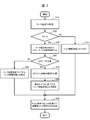
- FIG. 2 is an example of a flowchart of the control device 60 according to the first embodiment of the present invention.
- FIGS. 3 to 5 are used.
- step S10 at the start of the torque limiting process, the torque limiting coefficient calculation unit 61 acquires the motor temperature value Tm from the sensor 50 that detects the motor temperature.
- step S20 it is determined whether or not the motor temperature value Tm acquired from step S10 exceeds 0 ° C. If the motor temperature value Tm exceeds 0 ° C., the process proceeds to step S40, and if it is 0 ° C. or less, the process proceeds to step S30.
- step S30 it is determined that the torque limit is unnecessary, the torque limit coefficient is calculated as 100%, and the process proceeds to step S90.
- step S40 the motor temperature change rate ⁇ Tm is calculated from the deviation between the previous motor temperature value Tmz and the motor temperature value Tm.
- step S50 it is determined whether or not the motor temperature change rate ⁇ Tm calculated in step S40 exceeds a predetermined value. If the motor temperature change rate ⁇ Tm exceeds the predetermined value, the process proceeds to step S70, and if it is equal to or less than the predetermined value, the process proceeds to step S60.
- step S60 the torque limit coefficient Lmt is calculated from the initial value torque command coefficient map, and the process proceeds to step S90.
- step S70 the slope of the torque limit coefficient map is newly generated from the motor temperature change rate ⁇ Tm.
- FIG. 3 is a torque limit coefficient map. Note that FIG. 3A is a conventional torque limit coefficient map, and FIG. 3B is a torque limit coefficient map of the present invention.
- step S50 When the motor temperature change rate ⁇ Tm exceeds a predetermined value in step S50, the torque is limited as shown in FIG. 3B in the section of the motor temperature T1 to T2 of a certain constant value based on the motor temperature change rate ⁇ Tm. Change the slope of the coefficient map. Specifically, the torque limit coefficient map is set in the horizontal direction so that the torque limit value at T1 and T2 becomes closer as ⁇ Tm becomes larger, with the torque limit coefficient at T3, which is the intermediate temperature between the motor temperatures T1 and T2, as the fulcrum. Tilt to.
- step S80 the torque limit coefficient Lmt corresponding to the motor temperature value Tm is calculated from the torque limit coefficient map after the inclination is changed calculated in step S70.
- step S90 the torque limit coefficient Lmt calculated in step S30, step S60, or step S80 is multiplied by the torque command Trq acquired from the host controller to calculate the torque command Trq * after the limit, and the flowchart ends.
- the torque limiting unit calculates a limited torque command based on the motor temperature and limits the output torque of the motor.
- FIG. 4 is a diagram showing the contents of torque limitation during motor heating in the conventional method
- FIG. 5 is a diagram showing the transition of the inclination of the torque limiting coefficient map according to the present invention.
- Torque is limited from the first temperature limit T1 (time t1 on the horizontal axis) in FIG. 4, but due to the delay in conversion from current to heat generation and the delay in detecting the motor temperature value Tm, the control device 60 with respect to the motor temperature value Tm There is a delay in the reaction. Therefore, at the time t2, a phenomenon occurs in which the torque after limitation temporarily drops to Trq * 2 as shown in FIG. After that, while hunting the limit torque, at the time point t3 in FIG. 4, a point is formed that balances with the motor temperature value Tm at a predetermined post-limit torque value (continuous rated value), and the graph converges.
- the continuous rated value changes depending on the operating conditions such as the motor rotation speed, the atmospheric temperature, and the state of the cooling device.
- the upper graph of FIG. 5 is a graph of the motor temperature value Tm similar to that of FIG.
- the graphs at the bottom of FIG. 5 are a graph showing the time change rate of the motor temperature (hereinafter referred to as the temperature change rate ⁇ TCm) and a graph showing the slope of the torque limit coefficient map, respectively, with the time t as the horizontal axis.
- variable rate of the inclination of the torque limit coefficient map according to the embodiment of the present invention is determined based on the motor temperature change rate ⁇ TCm.
- the first temperature change rate is ⁇ TCm1.
- the temperature change rate ⁇ TCm becomes high by the time t1 when the torque limitation is started, as shown in the graph in the middle of FIG.
- the slope of the torque limit coefficient map is made small (horizontally). This corresponds to the change in the inclination of the torque limit coefficient map in FIG. 3 in the horizontal direction.
- the slope of the torque limit coefficient map can be changed within the range from the first slope S1 to the second slope S2, and the variable angle is limited.
- the slope of the torque limiting coefficient map changes within the variable range R of FIG. 3 (b).
- the slope of the torque limit coefficient map is the lower limit S1.
- the temperature change rate ⁇ TCm becomes 0 when the motor temperature value Tm reaches the highest point. From here, since the motor temperature value Tm starts to decrease, the temperature change rate ⁇ TCm rises again, and when the first temperature change rate ⁇ TCm1 is exceeded, the inclination of the torque limit coefficient map is reduced again.
- a temporary delay filter is added to multiply the deviation between the first temperature change rate ⁇ TCm1 and the motor temperature value Tm by a predetermined gain and suppress an excessive slope change. It was done.
- the torque of the torque limiting unit changes more slowly than when the time change rate of the motor temperature is equal to or less than the predetermined value. Limit the torque so that it does. Further, the torque limit amount is made variable by changing the inclination of the torque limit coefficient map, which is a relational expression between the motor temperature and the torque limit rate. Further, when the rate of change of the motor temperature is large, the inclination of the relational expression between the motor temperature and the torque limit rate can be reduced, and the current flowing through the motor so that the torque changes gently with the change of the motor temperature. To limit.
- the control device 60 limits the control device 60 to the PWM generation unit 63 that outputs a PWM drive signal to the inverter 40, and the PWM generation unit 63 based on the torque command from the upper control unit and the motor temperature.
- the torque limiting unit includes a torque limiting unit that outputs a rear torque command, and the torque limiting unit includes a torque limiting coefficient calculating unit 61 that calculates a torque limiting coefficient based on the motor temperature, and the torque command from the upper control unit.
- the post-restriction torque calculation unit 62 that outputs the post-restriction torque command to the PWM generation unit 63 based on the torque limit coefficient output from the torque limit coefficient calculation unit 61, and the torque limit coefficient
- the calculation unit 61 limits the output torque of the motor 30 based on the motor temperature when the motor temperature is higher than the predetermined temperature, and when the time change rate of the motor temperature is larger than the predetermined value, the calculation unit 61 limits the output torque.
- the torque is limited so that the torque changes more slowly than when the rate of change of the motor temperature with time is equal to or less than the predetermined value. Since this is done, the output of the motor does not drop more than necessary, and the motor can be protected.
- the torque limit coefficient calculation unit 61 of the control device 60 changes the torque limit amount by changing the inclination of the relational expression between the motor temperature and the torque limit rate. Since this is done, hunting can be suppressed according to the rate of change in the motor temperature.
- the torque limit coefficient calculation unit 61 of the control device 60 reduces the inclination of the relational expression between the motor temperature and the torque limit rate as the rate of change in the motor temperature increases. As a result, hunting can be suppressed without excessive torque limitation even in a transient state in which the motor temperature begins to rise sharply.
- the torque limiting unit of the control device 60 limits the current flowing through the motor 30 so that the torque changes gently with respect to the change in the motor temperature. Since this is done, the output of the vehicle does not change and the performance does not deteriorate.
- FIG. 6 is a diagram showing a configuration of a control device 60A showing a second embodiment of the present invention.
- the control device 60A adds a motor temperature compensation unit 64 to the control device 60 described with reference to FIG.
- the motor temperature value Tm is input by the torque limit coefficient calculation unit 61, but as shown in FIG. 6, the motor temperature estimated value TmA in which the detection delay and the detection error of the motor temperature value Tm are corrected is obtained. Generated and input by the motor temperature correction unit 64.
- the motor temperature detected by the control device 60 is a temperature corrected so as to approach the actual motor temperature with respect to the temperature detected by the sensor 50. Since this is done, hunting at the time of torque limitation can be further reduced.
- FIG. 7 is a torque limiting coefficient map of the control device 60B showing the third embodiment of the present invention.
- the torque limit coefficient map of FIG. 7 is the torque limit coefficient map of FIG. 3 which is the first embodiment, and the intersection T3 between T1 and T2 is changed depending on the operating conditions, the cooling conditions, and the like. That is, the fulcrum when changing the inclination of the relational expression between the motor temperature and the torque limit rate is variable.
- FIG. 7 An example of FIG. 7 is given.
- the point at which the limiting torque saturates is closer to T2 than T3 as shown in FIG.
- the time for torque limiting within the region A in FIG. 7 increases, so that the torque temporarily exceeds the expected torque. May be output. Therefore, by setting the intersection T3 to a point closer to T2 than T1 like T3B, torque hunting can be reduced while suppressing an unexpected temperature rise.
- the torque limit coefficient calculation unit 61 of the control device 60 makes the fulcrum when changing the inclination of the relational expression between the motor temperature and the torque limit rate variable. Since this is done, torque hunting can be reduced while suppressing an unexpected temperature rise due to environmental conditions.
- the present invention has described the case where the above embodiment is applied to a system in which a three-phase AC motor is mounted as a load, but the present invention is not limited to this, and can be applied to a system provided with a rotating machine. Is.
- the present invention has described the torque limiting function related to the motor temperature of the motor control device, it can also be applied to the output limitation at the temperature for other heat generating parts.
- the inverter of the motor drive device has a temperature detection circuit and the inverter is protected by limiting the output to the input of the detected temperature, the conversion from current to heat is delayed. Therefore, the configuration of the present invention is provided. There is a possibility that torque hunting can be suppressed by adopting.
Abstract
A control device 60 comprising a PWM generation unit 63 that outputs a PWM drive signal to an inverter 40, and a torque limiting unit that outputs a limited torque command to the PWM generation unit 63 on the basis of a motor temperature and a torque command from a higher-level control unit, the control device 60 being such that: the torque limiting unit has a torque limit coefficient calculation unit 61 that calculates a torque limit control coefficient on the basis of the motor temperature, and a limited torque calculation unit 62 that outputs the limited torque command to the PWM generation unit 63 on the basis of the torque command and the torque limiting coefficient; and the torque limit coefficient calculation unit 61 limits the output torque on the basis of the motor temperature when the motor temperature is higher than a prescribed temperature, and, when the rate of change over time of the motor temperature is greater than a prescribed value, limits the torque so that the torque varies more gradually than when the rate of change over time is less than or equal to the prescribed value.
Description
本発明は、制御装置に関する。
The present invention relates to a control device.
従来、電気自動車やハイブリッド自動車等の電動車両は、長時間の高速走行や坂道の登坂などによりモータの過負荷状態が継続すると、モータの温度が上昇し過熱状態になることで故障する恐れがある。そのため、モータの温度状態によって出力トルクを制限する技術が求められる。
Conventionally, electric vehicles such as electric vehicles and hybrid vehicles may break down due to the temperature of the motor rising and becoming overheated if the overloaded state of the motor continues due to long-time high-speed running or climbing a slope. .. Therefore, a technique for limiting the output torque according to the temperature state of the motor is required.
本願発明の背景技術として、下記の特許文献が知られている。特許文献1には、回生制御でのモータ出力の制限が開始される温度を、力行制御の温度よりも低くすることにより、回生制御時のモータの発熱をより効果的に抑制できる技術が開示されている。また、特許文献2には、モータ温度の変化率の所定基準により、モータの温度制限を変化させ、モータの温度保護と性能発揮を同時にできる技術が開示されている。
The following patent documents are known as background techniques of the present invention. Patent Document 1 discloses a technique capable of more effectively suppressing heat generation of a motor during regenerative control by lowering the temperature at which motor output limitation in regenerative control is started to be lower than the temperature in power running control. ing. Further, Patent Document 2 discloses a technique capable of changing the temperature limit of the motor according to a predetermined standard of the rate of change of the motor temperature, and simultaneously protecting the temperature of the motor and exhibiting its performance.
特許文献1の技術では、温度検出の過程で発生する遅れによるハンチングを抑制するために、トルク制限を開始するモータ温度を低くすると、モータの出力制限に入りやすくなり、加速時における高出力時間が短くなることが課題であった。
In the technique of Patent Document 1, if the motor temperature at which torque limitation is started is lowered in order to suppress hunting due to a delay that occurs in the process of temperature detection, it becomes easy to enter the output limitation of the motor, and the high output time during acceleration becomes high. The challenge was to shorten it.
また、特許文献2の技術では、温度変化によってトルク制限マップの傾きを変える方式があるが、モータ温度と制限トルクがつりあうポイントがトルク制限開始前の温度上昇量よって変化してしまい、連続で出力できるトルクが低くなることで、モータの性能を十分に発揮できないことが課題であった。
Further, in the technique of Patent Document 2, there is a method of changing the inclination of the torque limit map according to the temperature change, but the point where the motor temperature and the limit torque are balanced changes depending on the amount of temperature rise before the start of the torque limit, and the output is continuous. The problem is that the performance of the motor cannot be fully exhibited due to the low torque that can be produced.
本発明による制御装置は、インバータにPWM駆動信号を出力するPWM生成部と、上位制御部からのトルク指令とモータ温度とに基づいて、前記PWM生成部に制限後トルク指令を出力するトルク制限部と、を備え、前記トルク制限部は、前記モータ温度に基づいてトルク制限係数を算出するトルク制限係数算出部と、前記上位制御部からの前記トルク指令と、前記トルク制限係数算出部から出力される前記トルク制限係数に基づいて、前記PWM生成部に前記制限後トルク指令を出力する制限後トルク算出部と、を有し、前記トルク制限係数算出部は、前記モータ温度が所定の温度よりも高い場合には、前記モータ温度に基づいてモータの出力トルクを制限し、前記モータ温度の時間変化率が所定値より大きい場合には、前記モータ温度の時間変化率が前記所定値以下の場合に比べて、トルクが緩やかに変化するように前記トルクを制限する。
The control device according to the present invention includes a PWM generator that outputs a PWM drive signal to the inverter, and a torque limiter that outputs a torque command after limiting to the PWM generator based on a torque command from a higher-level control unit and a motor temperature. And, the torque limit unit is output from the torque limit coefficient calculation unit that calculates the torque limit coefficient based on the motor temperature, the torque command from the upper control unit, and the torque limit coefficient calculation unit. A post-limit torque calculation unit that outputs the post-restriction torque command to the PWM generation unit based on the torque limit coefficient, and the torque limit coefficient calculation unit has a motor temperature higher than a predetermined temperature. When it is high, the output torque of the motor is limited based on the motor temperature, and when the time change rate of the motor temperature is larger than the predetermined value, the time change rate of the motor temperature is equal to or less than the predetermined value. In comparison, the torque is limited so that the torque changes gently.
本発明によれば、モータの出力が必要以上に低下しない。
According to the present invention, the output of the motor does not decrease more than necessary.
以下、図面を用いて本発明の実施形態を説明する。
Hereinafter, embodiments of the present invention will be described with reference to the drawings.
(制御装置の構成、および第1の実施形態)
本発明の第1の実施形態に係る制御装置について図1~6を用いて説明する。図1は本発明の第1の実施形態を示す制御装置60の構成を表す図である。 (Structure of control device and first embodiment)
The control device according to the first embodiment of the present invention will be described with reference to FIGS. 1 to 6. FIG. 1 is a diagram showing a configuration of acontrol device 60 showing a first embodiment of the present invention.
本発明の第1の実施形態に係る制御装置について図1~6を用いて説明する。図1は本発明の第1の実施形態を示す制御装置60の構成を表す図である。 (Structure of control device and first embodiment)
The control device according to the first embodiment of the present invention will be described with reference to FIGS. 1 to 6. FIG. 1 is a diagram showing a configuration of a
制御装置60のシステム方式は、直流電源10の電圧を、コンタクタ20を介したインバータ40に出力して直流電圧を交流電圧に変換し、変換した交流電圧を交流モータ30(IPMSM。以降、モータ30)に電力供給するとともに、モータ30の制御を行うものである。例えば、ハイブリッド自動車の駆動系などへ適用された場合には、直流電源10はニッケル水素電池やリチウムイオン電池などの2次電池が使用される。その際、電圧は数百Vとなることが想定され、モータ30の出力軸は車軸へ接続されることが想定される。
In the system system of the control device 60, the voltage of the DC power supply 10 is output to the inverter 40 via the contactor 20, the DC voltage is converted into an AC voltage, and the converted AC voltage is converted into an AC motor 30 (IPMSM. Hereinafter, the motor 30). ), And also controls the motor 30. For example, when applied to a drive system of a hybrid vehicle, a secondary battery such as a nickel hydrogen battery or a lithium ion battery is used as the DC power supply 10. At that time, the voltage is expected to be several hundred V, and the output shaft of the motor 30 is assumed to be connected to the axle.
また、インバータ40は、IGBTなどの高速でスイッチングを行う素子が、直流電源10の正極側と負極側にそれぞれ3相分ずつ配置されている。この合計6つのスイッチング素子41のスイッチングにより、インバータ40から発生する電圧のパルス幅を変化させ、所定の電圧をモータ30へ印加する、パルス幅変調方式などが採用される。
Further, in the inverter 40, elements such as IGBTs that perform high-speed switching are arranged for three phases on the positive electrode side and the negative electrode side of the DC power supply 10. A pulse width modulation method or the like is adopted in which the pulse width of the voltage generated from the inverter 40 is changed by switching of the six switching elements 41 in total and a predetermined voltage is applied to the motor 30.
制御装置60は、トルク制限部と、PWM生成部63と、を備える。トルク制限部は、トルク制限係数算出部61と、制限後トルク算出部62と、を有する。
The control device 60 includes a torque limiting unit and a PWM generating unit 63. The torque limiting unit includes a torque limiting coefficient calculating unit 61 and a post-limiting torque calculating unit 62.
トルク制限係数算出部61は、モータ30の温度(以降、モータ温度)を検出するモータ温度センサ50(以降、センサ50)から取得したモータ温度値Tmに基づいて、トルク制限係数Lmtを制限後トルク算出部62に算出する。トルク制限係数Lmtの具体的な算出方法については、図2で後述する。
The torque limit coefficient calculation unit 61 limits the torque limit coefficient Lmt and then torques based on the motor temperature value Tm acquired from the motor temperature sensor 50 (hereinafter, sensor 50) that detects the temperature of the motor 30 (hereinafter, motor temperature). Calculated by the calculation unit 62. The specific calculation method of the torque limit coefficient Lmt will be described later in FIG.
制限後トルク算出部62は、上位コントローラ(上位制御部)からのトルク指令Trqに、トルク制限係数算出部61から取得したトルク制限係数Lmtをかけて、制限後トルク指令Trq*をPWM生成部63に出力する。
The post-limit torque calculation unit 62 multiplies the torque command Trq from the upper controller (upper control unit) by the torque limit coefficient Lmt acquired from the torque limit coefficient calculation unit 61, and outputs the post-limit torque command Trq * to the PWM generation unit 63. Output to.
PWM生成部63では制限後トルク算出部62から取得した制限後トルク指令Trq*に基づいて、実際値に近いトルクが出力されるようにPWM駆動信号を生成する。生成されたPWM駆動信号はインバータ40へ出力される。
The PWM generation unit 63 generates a PWM drive signal so that a torque close to the actual value is output based on the restricted torque command Trq * acquired from the restricted torque calculation unit 62. The generated PWM drive signal is output to the inverter 40.
図2は本発明の第1の実施形態に係る制御装置60のフローチャート例である。なお、各ステップの詳細な説明に際して、図3~図5を用いる。
FIG. 2 is an example of a flowchart of the control device 60 according to the first embodiment of the present invention. In addition, in the detailed explanation of each step, FIGS. 3 to 5 are used.
ステップS10では、トルク制限処理開始時に、トルク制限係数算出部61がモータ温度を検出するセンサ50からモータ温度値Tmを取得する。
In step S10, at the start of the torque limiting process, the torque limiting coefficient calculation unit 61 acquires the motor temperature value Tm from the sensor 50 that detects the motor temperature.
ステップS20では、ステップS10から取得したモータ温度値Tmが0℃を超えるかどうかを判定する。モータ温度値Tmが0℃を超える場合にはステップS40へ進み、0℃以下の場合にはステップS30へ進む。
In step S20, it is determined whether or not the motor temperature value Tm acquired from step S10 exceeds 0 ° C. If the motor temperature value Tm exceeds 0 ° C., the process proceeds to step S40, and if it is 0 ° C. or less, the process proceeds to step S30.
ステップS30では、トルク制限は不要と判定し、トルク制限係数を100%と算出してステップS90に進む。
In step S30, it is determined that the torque limit is unnecessary, the torque limit coefficient is calculated as 100%, and the process proceeds to step S90.
ステップS40では、モータ温度前回値Tmzとモータ温度値Tmの偏差とから、モータ温度変化率ΔTmを算出する。
In step S40, the motor temperature change rate ΔTm is calculated from the deviation between the previous motor temperature value Tmz and the motor temperature value Tm.
ステップS50では、ステップS40で算出したモータ温度変化率ΔTmが、所定値を超えているかどうかを判定する。モータ温度変化率ΔTmが所定値を超えている場合は、ステップS70に進み、所定値以下の場合はステップS60に進む。
In step S50, it is determined whether or not the motor temperature change rate ΔTm calculated in step S40 exceeds a predetermined value. If the motor temperature change rate ΔTm exceeds the predetermined value, the process proceeds to step S70, and if it is equal to or less than the predetermined value, the process proceeds to step S60.
ステップS60では、初期値のトルク指令係数マップからトルク制限係数Lmtを算出し、ステップS90に進む。
In step S60, the torque limit coefficient Lmt is calculated from the initial value torque command coefficient map, and the process proceeds to step S90.
ステップS70では、モータ温度変化率ΔTmからトルク制限係数マップの傾きを新規に生成する。
In step S70, the slope of the torque limit coefficient map is newly generated from the motor temperature change rate ΔTm.
ステップS70に係る図3の説明をする。図3はトルク制限係数マップである。なお、図3(a)は従来のトルク制限係数マップで、図3(b)が本発明のトルク制限係数マップである。
FIG. 3 according to step S70 will be described. FIG. 3 is a torque limit coefficient map. Note that FIG. 3A is a conventional torque limit coefficient map, and FIG. 3B is a torque limit coefficient map of the present invention.
ステップS50でモータ温度変化率ΔTmが所定値を超えている場合は、モータ温度変化率ΔTmに基づいて、ある一定値のモータ温度T1からT2の区間で、図3(b)のようにトルク制限係数マップの傾きを変化させる。具体的には、モータ温度T1とT2の中間温度であるT3においてのトルク制限係数を支点に、ΔTmが大きいほどT1とT2時のトルク制限値が近くなるように、トルク制限係数マップを水平方向に傾ける。
When the motor temperature change rate ΔTm exceeds a predetermined value in step S50, the torque is limited as shown in FIG. 3B in the section of the motor temperature T1 to T2 of a certain constant value based on the motor temperature change rate ΔTm. Change the slope of the coefficient map. Specifically, the torque limit coefficient map is set in the horizontal direction so that the torque limit value at T1 and T2 becomes closer as ΔTm becomes larger, with the torque limit coefficient at T3, which is the intermediate temperature between the motor temperatures T1 and T2, as the fulcrum. Tilt to.
ステップS80では、ステップS70で算出した傾き変更後のトルク制限係数マップからモータ温度値Tmに該当するトルク制限係数Lmtを算出する。
In step S80, the torque limit coefficient Lmt corresponding to the motor temperature value Tm is calculated from the torque limit coefficient map after the inclination is changed calculated in step S70.
ステップS90では、ステップS30またはステップS60またはステップS80で算出したトルク制限係数Lmtを、上位コントローラから取得したトルク指令Trqに掛けて、制限後トルク指令Trq*を算出し、フローチャートを終了する。
In step S90, the torque limit coefficient Lmt calculated in step S30, step S60, or step S80 is multiplied by the torque command Trq acquired from the host controller to calculate the torque command Trq * after the limit, and the flowchart ends.
以上フローチャートのように、トルク制限部は、モータ温度値Tmが所定の温度よりも高い場合には、モータ温度に基づいて制限されたトルク指令を算出し、モータの出力トルクを制限する。
As shown in the above flowchart, when the motor temperature value Tm is higher than the predetermined temperature, the torque limiting unit calculates a limited torque command based on the motor temperature and limits the output torque of the motor.
つづいて、ステップS90に関連する図4と図5の説明をする。図4は従来方式でのモータ加熱時のトルク制限の内容の図で、図5は本発明に係るトルク制限係数マップの傾きの推移を表す図である。
Next, FIGS. 4 and 5 related to step S90 will be described. FIG. 4 is a diagram showing the contents of torque limitation during motor heating in the conventional method, and FIG. 5 is a diagram showing the transition of the inclination of the torque limiting coefficient map according to the present invention.
まず、図4の従来方式の説明をする。上位コントローラからTrq*1相当のトルク指令が出力されている場合、モータ温度Tmは徐々に上昇していく。図4におけるトルク制限係数が100%の状態から開始され、図4のモータ温度T1に達するとトルク制限が開始される。
First, the conventional method shown in FIG. 4 will be described. When a torque command equivalent to Trq * 1 is output from the host controller, the motor temperature Tm gradually rises. The torque limit coefficient in FIG. 4 is started from the state of 100%, and the torque limit is started when the motor temperature T1 in FIG. 4 is reached.
図4の第一の制限温度T1(横軸の時間t1)からトルク制限をかけるが、電流から発熱への変換遅れやモータ温度値Tmの検出の遅れにより、モータ温度値Tmに対する制御装置60の反応に遅れが生じる。よって、時間t2の時には、制限後トルクが図4のようにTrq*2まで一時的に低下する現象が発生する。その後、制限トルクはハンチングしながら、図4のt3の時点において、所定の制限後トルク値でモータ温度値Tmとつり合う点ができ(連続定格値)、グラフが収束する。連続定格値は、モータ回転数などの運転条件や雰囲気温度、冷却装置の状態などにより変化する。
Torque is limited from the first temperature limit T1 (time t1 on the horizontal axis) in FIG. 4, but due to the delay in conversion from current to heat generation and the delay in detecting the motor temperature value Tm, the control device 60 with respect to the motor temperature value Tm There is a delay in the reaction. Therefore, at the time t2, a phenomenon occurs in which the torque after limitation temporarily drops to Trq * 2 as shown in FIG. After that, while hunting the limit torque, at the time point t3 in FIG. 4, a point is formed that balances with the motor temperature value Tm at a predetermined post-limit torque value (continuous rated value), and the graph converges. The continuous rated value changes depending on the operating conditions such as the motor rotation speed, the atmospheric temperature, and the state of the cooling device.
次に、図5を用いて本発明の制御装置60の機能の説明をする。図5の上のグラフは、図4と同様のモータ温度値Tmのグラフである。図5の下のグラフはそれぞれ時間tを横軸にした、モータ温度の時間変化率(以降、温度変化率ΔTCm)を表すグラフとトルク制限係数マップの傾きを表すグラフである。
Next, the function of the control device 60 of the present invention will be described with reference to FIG. The upper graph of FIG. 5 is a graph of the motor temperature value Tm similar to that of FIG. The graphs at the bottom of FIG. 5 are a graph showing the time change rate of the motor temperature (hereinafter referred to as the temperature change rate ΔTCm) and a graph showing the slope of the torque limit coefficient map, respectively, with the time t as the horizontal axis.
本発明の実施形態に係るトルク制限係数マップの傾きの可変の割合は、モータ温度変化率ΔTCmに基づいて決まる。ここで、第一の温度変化率をΔTCm1とする。
The variable rate of the inclination of the torque limit coefficient map according to the embodiment of the present invention is determined based on the motor temperature change rate ΔTCm. Here, the first temperature change rate is ΔTCm1.
通常、一定以上のトルク指令を連続で印加した場合には、図5の真ん中のグラフに示すように、トルク制限を開始する時間t1までに温度変化率ΔTCmが高い状態となる。この時、温度変化率ΔTCmは第1の温度変化率ΔTCm1より大幅に大きいため、トルク制限係数マップの傾きを小さく(水平方向に)する。これが図3のトルク制限係数マップの傾きの水平方向の変化にあたる。
Normally, when a torque command above a certain level is continuously applied, the temperature change rate ΔTCm becomes high by the time t1 when the torque limitation is started, as shown in the graph in the middle of FIG. At this time, since the temperature change rate ΔTCm is significantly larger than the first temperature change rate ΔTCm1, the slope of the torque limit coefficient map is made small (horizontally). This corresponds to the change in the inclination of the torque limit coefficient map in FIG. 3 in the horizontal direction.
トルク制限係数マップの傾きは、図5の下のグラフに示すように、第一の傾きS1から第二の傾きS2の範囲内で変更可能とし、可変角度を制限する。これにより、図3(b)の可変範囲R内でトルク制限係数マップの傾きが可変する。
As shown in the graph at the bottom of FIG. 5, the slope of the torque limit coefficient map can be changed within the range from the first slope S1 to the second slope S2, and the variable angle is limited. As a result, the slope of the torque limiting coefficient map changes within the variable range R of FIG. 3 (b).
時間t1では、温度変化率ΔTCmが大きいため、トルク制限係数マップの傾きは下限のS1となる。制限開始時間t1を過ぎると、トルク制限が開始されてモータ温度上昇も緩やかになるため、温度変化率ΔTCmが低下する。
At time t1, since the temperature change rate ΔTCm is large, the slope of the torque limit coefficient map is the lower limit S1. When the limit start time t1 is exceeded, the torque limit is started and the motor temperature rises slowly, so that the temperature change rate ΔTCm decreases.
時間t2では、モータ温度値Tmが最高点となるところで温度変化率ΔTCmは0となる。ここから、モータ温度値Tmは下降に転じるため温度変化率ΔTCmは再び上昇し、第一の温度変化率ΔTCm1を超えたところでトルク制限係数マップの傾きを再び減らす方向に動作させる。
At time t2, the temperature change rate ΔTCm becomes 0 when the motor temperature value Tm reaches the highest point. From here, since the motor temperature value Tm starts to decrease, the temperature change rate ΔTCm rises again, and when the first temperature change rate ΔTCm1 is exceeded, the inclination of the torque limit coefficient map is reduced again.
この後、第一の温度変化率ΔTCm1を温度変化率ΔTCmが上下するたびに、トルク制限係数マップの傾きを増減させ、時間t3に到達するとモータ温度値Tmとトルク制限値がつり合い、制限トルクがサチレーションする。この過程で、温度変化率ΔTCmがΔTCm1以内で収まるようになるとトルク制限係数マップの傾きがS2に定着、つまり初期状態のトルク制限係数マップの制限傾きになる。
After that, each time the temperature change rate ΔTCm fluctuates from the first temperature change rate ΔTCm1, the slope of the torque limit coefficient map is increased or decreased, and when the time t3 is reached, the motor temperature value Tm and the torque limit value are balanced and the limit torque is increased. Saturate. In this process, when the temperature change rate ΔTCm falls within ΔTCm1, the slope of the torque limit coefficient map is fixed in S2, that is, the slope of the torque limit coefficient map in the initial state becomes the limit slope.
なお、図5におけるトルク制限係数マップの傾きは、第一の温度変化率ΔTCm1とモータ温度値Tmの偏差に所定のゲインを乗算し、かつ過度な傾き変化を抑制するために一時遅れフィルタを追加したものである。
For the slope of the torque limit coefficient map in FIG. 5, a temporary delay filter is added to multiply the deviation between the first temperature change rate ΔTCm1 and the motor temperature value Tm by a predetermined gain and suppress an excessive slope change. It was done.
よって、図3の説明の通り、トルク制限部は、モータ温度の時間変化率が所定値より大きい場合には、モータ温度の時間変化率が所定値以下の場合に比べて、トルクが緩やかに変化するようにトルクを制限する。また、モータ温度とトルク制限率の関係式であるトルク制限係数マップの傾きを変化させることでトルク制限量を可変とする。さらに、モータ温度の変化率が大きい場合は、モータ温度とトルク制限率の関係式の傾きを小さくすることができ、モータ温度の変化に対してトルクが緩やかに変化するように、モータに流れる電流を制限する。
Therefore, as described in FIG. 3, when the time change rate of the motor temperature is larger than the predetermined value, the torque of the torque limiting unit changes more slowly than when the time change rate of the motor temperature is equal to or less than the predetermined value. Limit the torque so that it does. Further, the torque limit amount is made variable by changing the inclination of the torque limit coefficient map, which is a relational expression between the motor temperature and the torque limit rate. Further, when the rate of change of the motor temperature is large, the inclination of the relational expression between the motor temperature and the torque limit rate can be reduced, and the current flowing through the motor so that the torque changes gently with the change of the motor temperature. To limit.
以上説明した本発明の第1の実施形態によれば、以下の作用効果を奏する。
According to the first embodiment of the present invention described above, the following effects are exhibited.
(1)制御装置60は、制御装置60は、インバータ40にPWM駆動信号を出力するPWM生成部63と、上位制御部からのトルク指令とモータ温度とに基づいて、前記PWM生成部63に制限後トルク指令を出力するトルク制限部と、を備え、前記トルク制限部は、前記モータ温度に基づいてトルク制限係数を算出するトルク制限係数算出部61と、前記上位制御部からの前記トルク指令と、前記トルク制限係数算出部61から出力される前記トルク制限係数に基づいて、前記PWM生成部63に前記制限後トルク指令を出力する制限後トルク算出部62と、を有し、前記トルク制限係数算出部61は、前記モータ温度が所定の温度よりも高い場合には、前記モータ温度に基づいてモータ30の出力トルクを制限し、前記モータ温度の時間変化率が所定値より大きい場合には、前記モータ温度の時間変化率が前記所定値以下の場合に比べて、トルクが緩やかに変化するように前記トルクを制限する。このようにしたので、モータの出力が必要以上に低下せず、モータの保護も可能となる。
(1) The control device 60 limits the control device 60 to the PWM generation unit 63 that outputs a PWM drive signal to the inverter 40, and the PWM generation unit 63 based on the torque command from the upper control unit and the motor temperature. The torque limiting unit includes a torque limiting unit that outputs a rear torque command, and the torque limiting unit includes a torque limiting coefficient calculating unit 61 that calculates a torque limiting coefficient based on the motor temperature, and the torque command from the upper control unit. The post-restriction torque calculation unit 62 that outputs the post-restriction torque command to the PWM generation unit 63 based on the torque limit coefficient output from the torque limit coefficient calculation unit 61, and the torque limit coefficient The calculation unit 61 limits the output torque of the motor 30 based on the motor temperature when the motor temperature is higher than the predetermined temperature, and when the time change rate of the motor temperature is larger than the predetermined value, the calculation unit 61 limits the output torque. The torque is limited so that the torque changes more slowly than when the rate of change of the motor temperature with time is equal to or less than the predetermined value. Since this is done, the output of the motor does not drop more than necessary, and the motor can be protected.
(2)制御装置60のトルク制限係数算出部61は、モータ温度とトルク制限率の関係式の傾きを変化させることでトルク制限量を可変とする。このようにしたので、モータ温度の変化率に応じて、ハンチングを抑制できる。
(2) The torque limit coefficient calculation unit 61 of the control device 60 changes the torque limit amount by changing the inclination of the relational expression between the motor temperature and the torque limit rate. Since this is done, hunting can be suppressed according to the rate of change in the motor temperature.
(3)制御装置60のトルク制限係数算出部61は、モータ温度の変化率が大きいほど、モータ温度とトルク制限率の関係式の傾きを小さくする。このようにしたので、モータ温度が急激に上昇し始めた過渡状態であっても、過度なトルク制限とならずにハンチングが抑制できる。
(3) The torque limit coefficient calculation unit 61 of the control device 60 reduces the inclination of the relational expression between the motor temperature and the torque limit rate as the rate of change in the motor temperature increases. As a result, hunting can be suppressed without excessive torque limitation even in a transient state in which the motor temperature begins to rise sharply.
(4)制御装置60のトルク制限部は、モータ温度の変化に対してトルクが緩やかに変化するように、モータ30に流れる電流を制限する。このようにしたので、車両の出力が変化せず、性能が低下しない。
(4) The torque limiting unit of the control device 60 limits the current flowing through the motor 30 so that the torque changes gently with respect to the change in the motor temperature. Since this is done, the output of the vehicle does not change and the performance does not deteriorate.
(第2の実施形態)
本発明の第2の実施形態について図6を用いて説明する。図6は本発明の第2の実施形態を示す制御装置60Aの構成を表す図である。 (Second Embodiment)
A second embodiment of the present invention will be described with reference to FIG. FIG. 6 is a diagram showing a configuration of a control device 60A showing a second embodiment of the present invention.
本発明の第2の実施形態について図6を用いて説明する。図6は本発明の第2の実施形態を示す制御装置60Aの構成を表す図である。 (Second Embodiment)
A second embodiment of the present invention will be described with reference to FIG. FIG. 6 is a diagram showing a configuration of a control device 60A showing a second embodiment of the present invention.
制御装置60Aは、図1で説明した制御装置60にモータ温度補正部64を加えている。第1の実施形態では、トルク制限係数算出部61でモータ温度値Tmを入力することとしていたが、図6のようにモータ温度値Tmの検出遅れや検出誤差を補正したモータ温度推定値TmAをモータ温度補正部64で生成し入力する。
The control device 60A adds a motor temperature compensation unit 64 to the control device 60 described with reference to FIG. In the first embodiment, the motor temperature value Tm is input by the torque limit coefficient calculation unit 61, but as shown in FIG. 6, the motor temperature estimated value TmA in which the detection delay and the detection error of the motor temperature value Tm are corrected is obtained. Generated and input by the motor temperature correction unit 64.
第1の実施形態で示した、図4のようなトルク制限係数マップを用いたトルク制限を実施する場合に、モータ温度補正値を入力するとしても少なからず遅れ成分が含まれ、トルクハンチングが発生する可能性がある。そのため、図6のように、トルク制限係数算出部61の前の段階で、センサ50により検出した温度に対して実際のモータ温度に近づくようにモータ温度補正をする構成を適用することで、よりトルクハンチングの低減が可能となる。
When torque limiting using the torque limiting coefficient map as shown in FIG. 4 shown in the first embodiment, even if the motor temperature correction value is input, a considerable delay component is included and torque hunting occurs. there's a possibility that. Therefore, as shown in FIG. 6, by applying a configuration in which the motor temperature is corrected so as to approach the actual motor temperature with respect to the temperature detected by the sensor 50 in the stage before the torque limit coefficient calculation unit 61, it is possible to obtain more. Torque hunting can be reduced.
以上説明した本発明の第2の実施形態によれば、以下の作用効果を奏する。
According to the second embodiment of the present invention described above, the following effects are exhibited.
(5)制御装置60が検出するモータ温度は、センサ50により検出した温度に対して実際のモータ温度に近づくように補正された温度である。このようにしたので、トルク制限の際のハンチングをさらに低減できる。
(5) The motor temperature detected by the control device 60 is a temperature corrected so as to approach the actual motor temperature with respect to the temperature detected by the sensor 50. Since this is done, hunting at the time of torque limitation can be further reduced.
(第3の実施形態)
本発明の第3の実施形態について図7を用いて説明する。図7は本発明の第3の実施形態を示す制御装置60Bのトルク制限係数マップである。 (Third Embodiment)
A third embodiment of the present invention will be described with reference to FIG. FIG. 7 is a torque limiting coefficient map of the control device 60B showing the third embodiment of the present invention.
本発明の第3の実施形態について図7を用いて説明する。図7は本発明の第3の実施形態を示す制御装置60Bのトルク制限係数マップである。 (Third Embodiment)
A third embodiment of the present invention will be described with reference to FIG. FIG. 7 is a torque limiting coefficient map of the control device 60B showing the third embodiment of the present invention.
図7のトルク制限係数マップは、第1の実施形態である図3のトルク制限係数マップに、運転条件や冷却条件等によりT1とT2の間の交点T3を変化させている。つまり、モータ温度とトルク制限率の関係式の傾きの変化させる際の支点を可変としている。
The torque limit coefficient map of FIG. 7 is the torque limit coefficient map of FIG. 3 which is the first embodiment, and the intersection T3 between T1 and T2 is changed depending on the operating conditions, the cooling conditions, and the like. That is, the fulcrum when changing the inclination of the relational expression between the motor temperature and the torque limit rate is variable.
図7の例を挙げる。たとえば、制御装置の雰囲気温度が高い場合に、制限トルクがサチレーションするポイントが図3で示すようなT3よりもT2に近いポイントであることが想定されるケースがある。その場合に、モータ温度値TmがT3より高い状態でトルク制限係数マップの傾きを水平方向にすると、図7の領域A内でトルク制限をする時間が増えるため、一時的に想定以上のトルクの出力となる可能性がある。そこで、交点T3をT3BのようにT1よりもT2に近いポイントとすることで、想定以上の温度上昇も抑制しながらトルクハンチングを低減することができる。
An example of FIG. 7 is given. For example, when the atmospheric temperature of the control device is high, it may be assumed that the point at which the limiting torque saturates is closer to T2 than T3 as shown in FIG. In that case, if the inclination of the torque limiting coefficient map is made horizontal when the motor temperature value Tm is higher than T3, the time for torque limiting within the region A in FIG. 7 increases, so that the torque temporarily exceeds the expected torque. May be output. Therefore, by setting the intersection T3 to a point closer to T2 than T1 like T3B, torque hunting can be reduced while suppressing an unexpected temperature rise.
以上説明した本発明の第3の実施形態によれば、以下の作用効果を奏する。
According to the third embodiment of the present invention described above, the following effects are exhibited.
(6)制御装置60のトルク制限係数算出部61は、モータ温度とトルク制限率の関係式の傾きの変化させる際の支点を可変とする。このようにしたので、環境条件による想定以上の温度上昇を抑制しながら、トルクハンチングを低減することができる。
(6) The torque limit coefficient calculation unit 61 of the control device 60 makes the fulcrum when changing the inclination of the relational expression between the motor temperature and the torque limit rate variable. Since this is done, torque hunting can be reduced while suppressing an unexpected temperature rise due to environmental conditions.
以上、本発明は、負荷として3相交流モータが搭載されるシステムに上記実施形態を適用した場合について述べたが、これに限定されるものではなく、回転機を備えたシステムにも適用が可能である。
The present invention has described the case where the above embodiment is applied to a system in which a three-phase AC motor is mounted as a load, but the present invention is not limited to this, and can be applied to a system provided with a rotating machine. Is.
また、本発明はモータ制御装置のモータ温度に関するトルク制限機能について述べたが、ほかの発熱部位に対する温度での出力制限に対しても適応可能である。例えば、モータ駆動装置のインバータに温度検出回路があり、かつ検出温度を入力に出力を制限することでインバータを保護する場合には、電流から熱への変換に遅れが生じるため、本発明の構成を採用することでトルクハンチングを抑制できる可能性がある。
Further, although the present invention has described the torque limiting function related to the motor temperature of the motor control device, it can also be applied to the output limitation at the temperature for other heat generating parts. For example, when the inverter of the motor drive device has a temperature detection circuit and the inverter is protected by limiting the output to the input of the detected temperature, the conversion from current to heat is delayed. Therefore, the configuration of the present invention is provided. There is a possibility that torque hunting can be suppressed by adopting.
また、各実施形態や各種変形例はあくまで一例であり、発明の特徴が損なわれない限り、本発明はこれらの内容に限定されるものではない。同時に、上記では種々の実施形態や変形例を説明したが、本発明はこれらの内容に限定されるものではない。本発明の技術的思想の範囲内で考えられるその他の態様も本発明の範囲内に含まれる。
Further, each embodiment and various modifications are merely examples, and the present invention is not limited to these contents as long as the features of the invention are not impaired. At the same time, various embodiments and modifications have been described above, but the present invention is not limited to these contents. Other aspects conceivable within the scope of the technical idea of the present invention are also included within the scope of the present invention.
10 直流電源
20 コンタクタ
30 交流モータ
40 インバータ
41 スイッチング素子
50 モータ温度センサ
60 制御装置
61 トルク制限係数算出部
62 制限後トルク算出部
63 PWM生成部
64 モータ温度補正部 10DC power supply 20 Contactor 30 AC motor 40 Inverter 41 Switching element 50 Motor temperature sensor 60 Control device 61 Torque limit coefficient calculation unit 62 Torque limit coefficient calculation unit 62 Post-limit torque calculation unit 63 PWM generation unit 64 Motor temperature compensation unit
20 コンタクタ
30 交流モータ
40 インバータ
41 スイッチング素子
50 モータ温度センサ
60 制御装置
61 トルク制限係数算出部
62 制限後トルク算出部
63 PWM生成部
64 モータ温度補正部 10
Claims (6)
- インバータにPWM駆動信号を出力するPWM生成部と、
上位制御部からのトルク指令とモータ温度とに基づいて、前記PWM生成部に制限後トルク指令を出力するトルク制限部と、を備え、
前記トルク制限部は、
前記モータ温度に基づいてトルク制限係数を算出するトルク制限係数算出部と、
前記上位制御部からの前記トルク指令と、前記トルク制限係数算出部から出力される前記トルク制限係数に基づいて、前記PWM生成部に前記制限後トルク指令を出力する制限後トルク算出部と、を有し、
前記トルク制限係数算出部は、前記モータ温度が所定の温度よりも高い場合には、前記モータ温度に基づいてモータの出力トルクを制限し、前記モータ温度の時間変化率が所定値より大きい場合には、前記モータ温度の時間変化率が前記所定値以下の場合に比べて、トルクが緩やかに変化するように前記トルクを制限する制御装置。 A PWM generator that outputs a PWM drive signal to the inverter,
A torque limiting unit that outputs a torque command after limiting to the PWM generating unit based on a torque command from the upper control unit and a motor temperature is provided.
The torque limiting unit is
A torque limit coefficient calculation unit that calculates a torque limit coefficient based on the motor temperature, and a torque limit coefficient calculation unit.
The torque command from the upper control unit and the post-limit torque calculation unit that outputs the post-limit torque command to the PWM generation unit based on the torque limit coefficient output from the torque limit coefficient calculation unit. Have and
The torque limit coefficient calculation unit limits the output torque of the motor based on the motor temperature when the motor temperature is higher than the predetermined temperature, and when the time change rate of the motor temperature is larger than the predetermined value. Is a control device that limits the torque so that the torque changes more slowly than when the time change rate of the motor temperature is equal to or less than the predetermined value. - 請求項1に記載の制御装置であって、前記トルク制限係数算出部は、前記モータ温度とトルク制限率の関係式の傾きを変化させることで前記制限後トルク指令のトルク制限量を可変とする制御装置。 The control device according to claim 1, wherein the torque limit coefficient calculation unit makes the torque limit amount of the torque limit command after the limit variable by changing the inclination of the relational expression between the motor temperature and the torque limit rate. Control device.
- 請求項2に記載の制御装置であって、前記トルク制限係数算出部は、前記モータ温度の変化率が大きいほど、前記モータ温度とトルク制限率の関係式の傾きを小さくする制御装置。 The control device according to claim 2, wherein the torque limit coefficient calculation unit reduces the inclination of the relational expression between the motor temperature and the torque limit rate as the rate of change of the motor temperature increases.
- 請求項1に記載の制御装置であって、前記モータ温度は、センサにより検出した温度に対して実際の前記モータ温度に近づくように補正された温度である制御装置。 The control device according to claim 1, wherein the motor temperature is a temperature corrected so as to approach the actual motor temperature with respect to the temperature detected by the sensor.
- 請求項2に記載の制御装置であって、前記トルク制限係数算出部は、前記モータ温度とトルク制限率の関係式の傾きを変化させる際の支点を可変とする制御装置。 The control device according to claim 2, wherein the torque limit coefficient calculation unit makes a fulcrum variable when changing the inclination of the relational expression between the motor temperature and the torque limit rate.
- 請求項1に記載の制御装置であって、前記トルク制限部は、前記モータ温度の変化に対して前記トルクが緩やかに変化するように、前記モータに流れる電流を制限する制御装置。 The control device according to claim 1, wherein the torque limiting unit limits the current flowing through the motor so that the torque changes gently with respect to a change in the motor temperature.
Priority Applications (3)
| Application Number | Priority Date | Filing Date | Title |
|---|---|---|---|
| DE112020005881.6T DE112020005881T5 (en) | 2020-01-28 | 2020-12-15 | CONTROL DEVICE |
| US17/795,720 US20230068986A1 (en) | 2020-01-28 | 2020-12-15 | Control device |
| JP2021574517A JP7303910B2 (en) | 2020-01-28 | 2020-12-15 | Control device |
Applications Claiming Priority (2)
| Application Number | Priority Date | Filing Date | Title |
|---|---|---|---|
| JP2020-011301 | 2020-01-28 | ||
| JP2020011301 | 2020-01-28 |
Publications (1)
| Publication Number | Publication Date |
|---|---|
| WO2021153050A1 true WO2021153050A1 (en) | 2021-08-05 |
Family
ID=77078556
Family Applications (1)
| Application Number | Title | Priority Date | Filing Date |
|---|---|---|---|
| PCT/JP2020/046664 WO2021153050A1 (en) | 2020-01-28 | 2020-12-15 | Control device |
Country Status (4)
| Country | Link |
|---|---|
| US (1) | US20230068986A1 (en) |
| JP (1) | JP7303910B2 (en) |
| DE (1) | DE112020005881T5 (en) |
| WO (1) | WO2021153050A1 (en) |
Families Citing this family (2)
| Publication number | Priority date | Publication date | Assignee | Title |
|---|---|---|---|---|
| CN114633628B (en) * | 2022-03-21 | 2023-12-15 | 潍柴动力股份有限公司 | Over-temperature protection method and device, electronic equipment and storage medium |
| CN117411389A (en) * | 2023-12-14 | 2024-01-16 | 珠海格力电器股份有限公司 | Overheat protection method for direct current motor and direct current motor |
Citations (4)
| Publication number | Priority date | Publication date | Assignee | Title |
|---|---|---|---|---|
| JP2003304604A (en) * | 2002-04-09 | 2003-10-24 | Nissan Motor Co Ltd | Method and apparatus for controlling motor |
| WO2017163609A1 (en) * | 2016-03-25 | 2017-09-28 | 株式会社デンソー | Control device of motor |
| JP2018102102A (en) * | 2016-12-22 | 2018-06-28 | トヨタ自動車株式会社 | Motor system |
| WO2018142952A1 (en) * | 2017-02-02 | 2018-08-09 | 日立オートモティブシステムズ株式会社 | Motor control device |
Family Cites Families (1)
| Publication number | Priority date | Publication date | Assignee | Title |
|---|---|---|---|---|
| JP2000032602A (en) | 1998-07-10 | 2000-01-28 | Toyota Motor Corp | Apparatus and method for controlling motor temperature |
-
2020
- 2020-12-15 DE DE112020005881.6T patent/DE112020005881T5/en active Pending
- 2020-12-15 JP JP2021574517A patent/JP7303910B2/en active Active
- 2020-12-15 US US17/795,720 patent/US20230068986A1/en active Pending
- 2020-12-15 WO PCT/JP2020/046664 patent/WO2021153050A1/en active Application Filing
Patent Citations (4)
| Publication number | Priority date | Publication date | Assignee | Title |
|---|---|---|---|---|
| JP2003304604A (en) * | 2002-04-09 | 2003-10-24 | Nissan Motor Co Ltd | Method and apparatus for controlling motor |
| WO2017163609A1 (en) * | 2016-03-25 | 2017-09-28 | 株式会社デンソー | Control device of motor |
| JP2018102102A (en) * | 2016-12-22 | 2018-06-28 | トヨタ自動車株式会社 | Motor system |
| WO2018142952A1 (en) * | 2017-02-02 | 2018-08-09 | 日立オートモティブシステムズ株式会社 | Motor control device |
Also Published As
| Publication number | Publication date |
|---|---|
| DE112020005881T5 (en) | 2022-09-15 |
| JP7303910B2 (en) | 2023-07-05 |
| US20230068986A1 (en) | 2023-03-02 |
| JPWO2021153050A1 (en) | 2021-08-05 |
Similar Documents
| Publication | Publication Date | Title |
|---|---|---|
| US8022650B2 (en) | Control apparatus of electric motor | |
| EP1881596B1 (en) | Motor drive system control device and electric vehicle using the same | |
| WO2021153050A1 (en) | Control device | |
| US8593843B2 (en) | Electric power conversion device capable of suppressing electric oscillations | |
| CN111277182B (en) | Depth flux weakening system of permanent magnet synchronous motor for vehicle and control method thereof | |
| JP3598975B2 (en) | Control device for fuel cell vehicle | |
| WO2005093943A1 (en) | Controller of permanent magnet synchronous motor | |
| US9935567B2 (en) | Rotating electric machine control device | |
| US11104374B2 (en) | Motor control device, electrically driven actuator product, and electrically driven power steering device | |
| US11831265B2 (en) | Motor control device | |
| JP2006141095A (en) | Device for controlling drive of permanent magnet type synchronous motor | |
| JP4140241B2 (en) | Motor drive control device, drive control method, and recording medium storing program for realizing the method | |
| JP7183740B2 (en) | Inverter device | |
| US11502631B2 (en) | Vector flux weakening control system for permanent magnet synchronous motor of electric drive system | |
| CN109586646B (en) | Angle error self-adaption method for permanent magnet synchronous motor | |
| EP2165409B1 (en) | System and method for limiting input voltage to a power delivery system having regeneration capability | |
| JP3622410B2 (en) | Control method of electric motor by inverter | |
| JP4123335B2 (en) | Speed sensorless control device for induction motor | |
| JP2005086919A (en) | Load-driving device and computer-readable recording medium recording program for making computer execute its control | |
| JP7238424B2 (en) | electric motor drive | |
| JP6658576B2 (en) | Inverter control device | |
| JP2023072564A (en) | Motor control method and motor control device | |
| JP5418206B2 (en) | Motor control device | |
| JP2020114076A (en) | Motor control device | |
| JPH08242576A (en) | Power converter |
Legal Events
| Date | Code | Title | Description |
|---|---|---|---|
| 121 | Ep: the epo has been informed by wipo that ep was designated in this application |
Ref document number: 20916350 Country of ref document: EP Kind code of ref document: A1 |
|
| ENP | Entry into the national phase |
Ref document number: 2021574517 Country of ref document: JP Kind code of ref document: A |
|
| 122 | Ep: pct application non-entry in european phase |
Ref document number: 20916350 Country of ref document: EP Kind code of ref document: A1 |