WO2021152866A1 - 二重羽根風力発電機 - Google Patents
二重羽根風力発電機 Download PDFInfo
- Publication number
- WO2021152866A1 WO2021152866A1 PCT/JP2020/004446 JP2020004446W WO2021152866A1 WO 2021152866 A1 WO2021152866 A1 WO 2021152866A1 JP 2020004446 W JP2020004446 W JP 2020004446W WO 2021152866 A1 WO2021152866 A1 WO 2021152866A1
- Authority
- WO
- WIPO (PCT)
- Prior art keywords
- wind power
- turbine
- leeward
- power generator
- turntable
- Prior art date
- Legal status (The legal status is an assumption and is not a legal conclusion. Google has not performed a legal analysis and makes no representation as to the accuracy of the status listed.)
- Ceased
Links
Images


Classifications
-
- F—MECHANICAL ENGINEERING; LIGHTING; HEATING; WEAPONS; BLASTING
- F03—MACHINES OR ENGINES FOR LIQUIDS; WIND, SPRING, OR WEIGHT MOTORS; PRODUCING MECHANICAL POWER OR A REACTIVE PROPULSIVE THRUST, NOT OTHERWISE PROVIDED FOR
- F03D—WIND MOTORS
- F03D80/00—Details, components or accessories not provided for in groups F03D1/00 - F03D17/00
-
- Y—GENERAL TAGGING OF NEW TECHNOLOGICAL DEVELOPMENTS; GENERAL TAGGING OF CROSS-SECTIONAL TECHNOLOGIES SPANNING OVER SEVERAL SECTIONS OF THE IPC; TECHNICAL SUBJECTS COVERED BY FORMER USPC CROSS-REFERENCE ART COLLECTIONS [XRACs] AND DIGESTS
- Y02—TECHNOLOGIES OR APPLICATIONS FOR MITIGATION OR ADAPTATION AGAINST CLIMATE CHANGE
- Y02E—REDUCTION OF GREENHOUSE GAS [GHG] EMISSIONS, RELATED TO ENERGY GENERATION, TRANSMISSION OR DISTRIBUTION
- Y02E10/00—Energy generation through renewable energy sources
- Y02E10/70—Wind energy
- Y02E10/72—Wind turbines with rotation axis in wind direction
Definitions
- the present invention relates to a wind power generator.
- wind power generation is one of the promising means, and many are being constructed and planned in places with good wind conditions around the world. There are more than a dozen manufacturers in Europe, the United States, China, India, etc., and each company is competing. On land, large wind turbines with three blades on the horizontal axis, 1 MW to 3 MW class, are the mainstay, and at sea, super large wind turbines of 3 MW to 7 MW class are being developed.
- the two ends of the rotor with permanent magnets and the two ends of the stator with winding coil are supported by fixed bearings, and the gap between the permanent magnets and the coil is at regular intervals. Need to rotate.
- the turntable to which the windward front turbine is attached and the shaft are directly connected the shaft is directly connected to the rotor with permanent magnets, and the windward bearing and the leeward bearing of the fixed housing are supported at two points before and after both ends and rotate as one. do.
- the turntable to which the leeward rear turbine is attached and the conduction pipe are directly connected the conduction pipe is directly connected to the stator with a coil, and the conduction pipe is the bearing provided on the leeward shaft, and the leeward outer ring bearing and inner ring bearing of the fixed housing. It is sandwiched between them, supported at two points before and after both ends, and rotates as one. As a result, even if the size of the generator is increased, stable rotation is possible while maintaining a constant interval between the permanent magnet and the coil.
- FIG. 1 is an explanatory view showing a cross-sectional view of the generator.
- FIG. 2 is an explanatory view showing a vertical cross-sectional view of the generator.
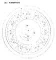
- FIG. 3 is an explanatory view showing a state in which the blades are attached to the turntable.
- FIG. 4 is a diagram showing a state in which a weight is attached to the tip of the outer periphery of the blade.
- FIG. 5 is a diagram showing a state in which four wind power generators are installed in the turret. (Example 5)
- a windward front turbine and a leeward rear turbine are installed with a generator with an output of 250 kW or more in between, and the upper and lower columns that support the central part of the generator are placed above and below the floor and ceiling of the turret via thrust self-aligning roller bearings.
- Four integrated wind power generators which are fixed in two places and have a directional steering wheel at the leeward rear of the wind turbine, are installed in the turret to increase the total output to 1 MW or more.
- FIG. 1 is a cross-sectional view of an embodiment of a generator, in which a shaft diameter is 20 cm, a length is 2.95 m, a permanent magnet rotor diameter is 1 m, a length is 2.35 m, a coil stator diameter is 1.3 m, and a length is 2. 55m, housing diameter 1.6m, length 2.95m, this size enables output of 250kW or more.
- FIG. 2 is a vertical cross-sectional view of an embodiment of a generator.
- the number of poles of the outer coil is 12 poles
- the number of poles of the inner permanent magnet NS is 8 poles
- the blade diameter is 10 m
- the wind speed is 10 m / s
- the rotation speed is about. 3 rotations / second, frequency 288Hz AC power generation, converted to DC with a converter, converted to AC 50Hz 60Hz with an inverter via a storage battery, and connected to the system.
- FIG. 3 shows an embodiment in which the blades are attached to the turntable, and the diameter of the upwind turntable is 1.2 m, the diameter of the downwind turntable is 1.4 m, the blade size is 5.5 m, the width is 0.5 m, and the thickness is 5 cm.
- the mounting angle is a fixed pitch of 45 degrees on the windward side blade and 35 degrees on the leeward side blade, and the front and rear are balanced and the rotation speed is designed to be the same.
- the windward front turbine and the leeward rear turbine do not overlap with each other toward the wind, and the wind force can be efficiently taken in.
- the mounting area of the turntable and blades can be increased, making a more durable wind turbine.
- FIG. 4 is a diagram in which a weight is attached to the outer peripheral tip of the blade. As a result, centrifugal force is applied to the rotation of the blades, and a smoother rotational force is conducted to the generator.
- FIG. 5 shows an example in which four wind power generators are installed in a turret.
- Five layers of partition floors are provided at intervals of 12 m from the top with a side of 12 m and an equilateral triangle height of 57.5 m, and four wind power generators are installed between them. do.
- the upper and lower columns that support the central part of the generator are fixed at places on the floor and ceiling of the turret via thrust self-aligning roller bearings to create a structure that can withstand strong winds.
- a rudder will be installed at the rear of the leeward side so that the wind turbine always faces the front of the wind.
- One of the three pillars of the turret is equipped with a permanent ladder, and in the event of a breakdown, workers can use the ladder to quickly repair without a mobile crane.
- chain blocks are used for repairs.
- strong wind areas the wind direction is determined by the rudder without a wind tunnel, and in weak wind areas, a wind tunnel with a trumpet-shaped opening on the leeward side is worn to determine the direction of the windmill and increase the wind speed inside the wind tunnel to increase power generation efficiency. ..
Landscapes
- Engineering & Computer Science (AREA)
- Life Sciences & Earth Sciences (AREA)
- Sustainable Development (AREA)
- Sustainable Energy (AREA)
- Chemical & Material Sciences (AREA)
- Combustion & Propulsion (AREA)
- Mechanical Engineering (AREA)
- General Engineering & Computer Science (AREA)
- Wind Motors (AREA)
Priority Applications (2)
| Application Number | Priority Date | Filing Date | Title |
|---|---|---|---|
| PCT/JP2020/004446 WO2021152866A1 (ja) | 2020-01-30 | 2020-01-30 | 二重羽根風力発電機 |
| JP2021574436A JPWO2021152866A1 (https=) | 2020-01-30 | 2020-01-30 |
Applications Claiming Priority (1)
| Application Number | Priority Date | Filing Date | Title |
|---|---|---|---|
| PCT/JP2020/004446 WO2021152866A1 (ja) | 2020-01-30 | 2020-01-30 | 二重羽根風力発電機 |
Publications (1)
| Publication Number | Publication Date |
|---|---|
| WO2021152866A1 true WO2021152866A1 (ja) | 2021-08-05 |
Family
ID=77079821
Family Applications (1)
| Application Number | Title | Priority Date | Filing Date |
|---|---|---|---|
| PCT/JP2020/004446 Ceased WO2021152866A1 (ja) | 2020-01-30 | 2020-01-30 | 二重羽根風力発電機 |
Country Status (2)
| Country | Link |
|---|---|
| JP (1) | JPWO2021152866A1 (https=) |
| WO (1) | WO2021152866A1 (https=) |
Citations (3)
| Publication number | Priority date | Publication date | Assignee | Title |
|---|---|---|---|---|
| KR200379582Y1 (ko) * | 2004-11-03 | 2005-03-24 | 이정우 | 동축반전 풍력발전기 |
| JP2012107535A (ja) * | 2010-11-15 | 2012-06-07 | Sadao Nakamura | 二軸反転式発電装置及びその制御方法 |
| JP2017061917A (ja) * | 2015-09-24 | 2017-03-30 | 株式会社G・T・R | 風洞付きwタービン発電機 |
-
2020
- 2020-01-30 JP JP2021574436A patent/JPWO2021152866A1/ja active Pending
- 2020-01-30 WO PCT/JP2020/004446 patent/WO2021152866A1/ja not_active Ceased
Patent Citations (3)
| Publication number | Priority date | Publication date | Assignee | Title |
|---|---|---|---|---|
| KR200379582Y1 (ko) * | 2004-11-03 | 2005-03-24 | 이정우 | 동축반전 풍력발전기 |
| JP2012107535A (ja) * | 2010-11-15 | 2012-06-07 | Sadao Nakamura | 二軸反転式発電装置及びその制御方法 |
| JP2017061917A (ja) * | 2015-09-24 | 2017-03-30 | 株式会社G・T・R | 風洞付きwタービン発電機 |
Also Published As
| Publication number | Publication date |
|---|---|
| JPWO2021152866A1 (https=) | 2021-08-05 |
Similar Documents
| Publication | Publication Date | Title |
|---|---|---|
| Möllerström et al. | A historical review of vertical axis wind turbines rated 100 kW and above | |
| US8464990B2 (en) | Pole mounted rotation platform and wind power generator | |
| US20090220342A1 (en) | Shaftless vertical axis wind turbine | |
| US6857846B2 (en) | Stackable vertical axis windmill | |
| EP2893186B1 (en) | Vertical axis wind turbine | |
| US8629570B1 (en) | Wind turbine blades with reinforcing, supporting and stabilizing components and enlarged swept area | |
| US9234498B2 (en) | High efficiency wind turbine | |
| US20090250938A1 (en) | Wind turbine incorporated in an electric transmission tower | |
| CN101368544A (zh) | 组合式共轴垂直轴风力发电机 | |
| US20130200618A1 (en) | High efficiency wind turbine | |
| CN106930899B (zh) | 一种风机内的偏航电机的供电系统及供电方法 | |
| CN114508457A (zh) | 一种双发电模式发电机组和海上风电系统 | |
| WO2021152866A1 (ja) | 二重羽根風力発電機 | |
| KR101548628B1 (ko) | 풍력발전기용 수직축형 풍차장치 | |
| Stavrakakis et al. | 2.10-Electrical parts of wind turbines | |
| JP2012002069A (ja) | ベルシェープ式クロスフロー・ダリウス方式複合型小型風力発電装置 | |
| CN211852049U (zh) | 一种旋球风力发电独立运行系统及具有该系统的发电装置 | |
| CN102322400A (zh) | 一种带有尾舵的多转子风力发电系统 | |
| CN209228531U (zh) | 叶片及垂直轴风力发电机组 | |
| CN115585091B (zh) | 一种水平轴上下风向双风轮直驱风力发电机组 | |
| CN204553094U (zh) | 涡旋风风力发电机 | |
| CN207004726U (zh) | 一种双涡轮风力发电机 | |
| CN205349613U (zh) | 组合立体风力发电机 | |
| Samantaray et al. | A study of wind energy potential in India | |
| CN219549022U (zh) | 风力涡轮机以及风力发电设备 |
Legal Events
| Date | Code | Title | Description |
|---|---|---|---|
| 121 | Ep: the epo has been informed by wipo that ep was designated in this application |
Ref document number: 20916547 Country of ref document: EP Kind code of ref document: A1 |
|
| NENP | Non-entry into the national phase |
Ref country code: DE |
|
| ENP | Entry into the national phase |
Ref document number: 2021574436 Country of ref document: JP Kind code of ref document: A |
|
| 122 | Ep: pct application non-entry in european phase |
Ref document number: 20916547 Country of ref document: EP Kind code of ref document: A1 |