WO2021148571A1 - Snowboard binding having a highback with a plurality of closed positions determined by a blocking means with a plurality of catches - Google Patents
Snowboard binding having a highback with a plurality of closed positions determined by a blocking means with a plurality of catches Download PDFInfo
- Publication number
- WO2021148571A1 WO2021148571A1 PCT/EP2021/051393 EP2021051393W WO2021148571A1 WO 2021148571 A1 WO2021148571 A1 WO 2021148571A1 EP 2021051393 W EP2021051393 W EP 2021051393W WO 2021148571 A1 WO2021148571 A1 WO 2021148571A1
- Authority
- WO
- WIPO (PCT)
- Prior art keywords
- base
- lever
- support shell
- lug
- snowboard binding
- Prior art date
Links
Images


Classifications
-
- A—HUMAN NECESSITIES
- A63—SPORTS; GAMES; AMUSEMENTS
- A63C—SKATES; SKIS; ROLLER SKATES; DESIGN OR LAYOUT OF COURTS, RINKS OR THE LIKE
- A63C10/00—Snowboard bindings
- A63C10/24—Calf or heel supports, e.g. adjustable high back or heel loops
-
- A—HUMAN NECESSITIES
- A63—SPORTS; GAMES; AMUSEMENTS
- A63C—SKATES; SKIS; ROLLER SKATES; DESIGN OR LAYOUT OF COURTS, RINKS OR THE LIKE
- A63C10/00—Snowboard bindings
- A63C10/02—Snowboard bindings characterised by details of the shoe holders
- A63C10/04—Shoe holders for passing over the shoe
- A63C10/045—Shoe holders for passing over the shoe with means to ease introduction of the shoe, e.g. by collapsing upstanding shoe holder parts
-
- A—HUMAN NECESSITIES
- A63—SPORTS; GAMES; AMUSEMENTS
- A63C—SKATES; SKIS; ROLLER SKATES; DESIGN OR LAYOUT OF COURTS, RINKS OR THE LIKE
- A63C2203/00—Special features of skates, skis, roller-skates, snowboards and courts
- A63C2203/10—Special features of skates, skis, roller-skates, snowboards and courts enabling folding, collapsing
Definitions
- the invention relates to a snowboard binding comprising more particularly a base, a support shell movable relative to the base and a pedal for controlling the support shell when putting on the boot, in rotation with respect to the base.
- base between an open position and a closed position.
- Means are provided to block the rotation of the support shell relative to the base in the closed position, against the elastic return of a lever.
- the medium includes two notches to engage with the lever.
- the means provided for blocking the support shell relative to the base comprises a spout retracted into a housing provided in each of the two lateral arms of the pedal, to engage with the resilient return lever mounted around an axis of rotation relative to the base.
- the two jaws form two detent notches with two ends of the lever, opposite with respect to the axis of rotation and received in the housings of the lateral arms of the pedal.
- Another example of this type of snowboard binding is provided by the document EP 0824942 wherein the two notches result from a recess formed in two lateral arms of the pedal, to engage with the resilient return lever, mounted around an axis of rotation relative to the base.
- the two notches result from a latch fixed on each side of the pedal to engage with the elastic return lever, fixed to the base.
- the resilient return lever is manually flipped to release the support shell from the closed position and allow removal.
- One of the aims of the invention is thus to modify the type of snowboard binding described above, to ensure that the support shell is locked in the closed position, in all circumstances.
- the notched means comprises a wheel provided with a notch forming the fork receiving the lug.
- the wheel can be rotatable relative to the support shell and the lug fixed in the base.
- the wheel can be movable relative to the base and the lug, fixed in the support shell or in the pedal.
- the lever comprises a first movable arm in rotation with respect to the support shell and a second arm, articulated to the first arm and snapped with the notched means, which is fixed in the support shell.
- the first arm of the lever provided with a notch forming the fork, opposite the second arm and the lug being fixed in the base.
- the first arm of the lever is an articulated hoop with two shell sides of the support shell.
- a bottom-of-shell of the support shell or the base comprises a hinge bearing, mounted around the axis of rotation of the support shell relative to the base. , serving as a guide stop in any position of the support shell, between the open position and the closed positions, when putting on and taking off.
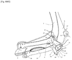
- Fig. 1 shows in side view an example of the first embodiment, in which the lug is carried by the pedal.
- Fig. 2 shows a side view of an example of the first embodiment, in which the lug is carried by the support shell.
- Fig. 3 shows a side view of another example of the first embodiment, in which the lug is carried on the support shell.
- Fig. 4 shows a side view of the first embodiment, in which the lug is carried by the base.
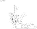
- Fig. 5 shows in side view an example of the second embodiment in which the lug is carried by the base, illustrating a first closed position.
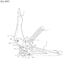
- Fig. 6 shows in side view an example of the second embodiment in which the lug is carried by the base, illustrating a second closed position.
- Fig. 7 shows in side view an example of a variant of the first embodiment in which the lug is carried by the support shell.
- a snowboard binding illustrated by one of Figures 1 to 7, comprises a base 1, a support shell 3, a pedal 5 and a strap 7.
- the support shell 3 is movable around the axis of rotation A1 carried by the base 1.
- the pedal 5 and the strap 7 are provided to control the support shell 3 respectively when putting on and taking off, between an open position and a closed position.
- the support shell 3 comprises a bottom-of-shell 9 and two side-shell 11.
- the pedal 5 is articulated to the two side-shell 11 about an axis of rotation A2.
- the strap 7 is articulated to the support shell 3 around an axis of rotation A3.
- Means 15, 16 are provided to block the rotation of the support shell 3 relative to the base 1 in the closed position, against an elastic return lever 13, 13a, 13b. This means 15, 16 comprises two or more detent notches 17.
- the resilient return lever includes an operating arm 12 to be released manually in order to unlock the support shell from the closed position and allow the release.
- the snowboard binding comprises a lug 21 received in a fork 20 of the means 15, 16 with notches 17 or of the lever 13, 13a, 13b for driving the notched means or the lever in rotation, by clicking. the lever of one of the notches 17 and by engaging with the other notch 17 during the boot.
- Figures 1 to 4 illustrate a first embodiment, in which the means 15 with notches 17 comprises a cam or a wheel provided with a notch 23 forming the fork 20 receiving the lug 21.
- the wheel 15 is carried by the base 1 around an axis of rotation A5 to be controlled by the lug 21, carried, Figure 1, by two side arms 19 themselves carrying the pedal 5 or carried, Figure 2 or 3, by the shell sides 11, in this case along the axis A3 of articulation of the strap 7.
- the resilient return lever 13 is movable relative to the base 1 around an axis of rotation A4 and provided with a notch 25 to engage with the notches 17 of the wheel 15.
- the elastic return of the lever 13, obtained by a means known in itself and not shown in the figures, such as a spring, allows it to be in abutment against the wheel 15 while the latter is rotated by the lug 21.
- the drive of the wheel 15 by the lug 21 allows, while the support shell 3 is rotated around the axis A1 by the pedal 5 during the boot, the lever 13 to unclip a notch 17 to snap into place with the next notch, so that the wheel 15 orders the succession of the various closed positions as a function of the succession of notches.
- the wheel 15 is movable in rotation relative to the sidewalls 11 and the lug 21 is fixed to the base 1.
- the resiliently return lever 13 is also movable in rotation by with respect to the sidewalls 11. Note that, in this exemplary embodiment, the lateral arms 19 of the pedal 5 are only articulated to the support shell 3, while they are also articulated to the base 1 in the example of figure 3.
- Figures 5 and 6 illustrate a second embodiment, in which the lever 13 comprises a first arm 13a movable relative to the support shell 3 about an axis of rotation A4 and a second arm 13b, articulated to the first arm 13a around an axis of rotation A6 and snapped with the means 16 with notches 17, which is fixed to the support shell 3.
- the first arm 13a is provided with a notch 23 forming the fork, opposite to the second arm 13b while the lug 21 is fixed in the base 1.
- the drive of the first arm 13a by the lug 21 allows the second arm 13b, while the support shell 3 is rotated around the axis A1 by the pedal 5 during the boot, to unclip by a notch 17 to engage with the next notch, so that the means 16 orders the succession of the different closing positions according to the succession of notches.
- any notch of the means 16 forms, with the articulation of the first arm to the support shell and the articulation of the second arm to the first arm, a locking triangle T, in any closed position of the shell. support.
- Figure 5 illustrates a closed position determined by a first notch, while in Figure 6, the closed position is determined by a last notch.
- Figures 1 to 6 illustrate the invention more particularly in the case where the hull bottom 9 or the base 1 comprises a hinge bearing 27 mounted around the axis of rotation A1, serving as a guide stop in any position of the support shell 3 between the open position and the various closed positions, when putting on and taking off.
- the guide stop is used to guide and pre-position a user's boot 2, in any position between the open position and the various closed positions.
- the first arm 13a of the lever 13 is a hoop on which the second arm 13b is articulated.
- the hoop being articulated to the two sidewalls 11, it advantageously cooperates with a single means 16 with notches 17 fixed to the support hull to distribute in a balanced manner the drive of the two sidewalls 11 controlled by the lug 21.
- the risk is avoided that the notches snapped onto one and the other sidewall 11 are not homologous and lead to a slight torsion of the support shell 3.
- the invention in general, applies to any snowboard binding which, according to the introductory disclosure, comprises a support shell movable relative to the base.
- FIG. 7 illustrates a variant of the first embodiment, which differs from the example given by FIG. 2 in that the axis A1 of rotation of the bearing shell 3 relative to the base 1 passes by two pivot connections 28 arranged on each of the two shell-sidewalls 11. Unlike the previous illustrative examples, the two pivot connections 28 do not form a hinge bearing but only two point connections such as rivets.
Landscapes
- Mechanical Control Devices (AREA)
- Footwear And Its Accessory, Manufacturing Method And Apparatuses (AREA)
Abstract
Snowboard binding comprising a base (1), a highback (3) that is rotatable with respect to the base (1), a pedal (5) for making the highback (3), when being fastened around a boot, move between an open position and a closed position, and a means (15) for preventing the highback (3) from rotating with respect to the base (1) in the closed position, counter to the elastic return of a lever (13), the means (15) comprising two catches (17) for engaging with the lever. According to the invention, the snowboard binding comprises a peg (21) received in a fork of the means (15) with catches (17) or of the lever (13) in order to drive the means with catches or the lever in rotation, by disengaging the lever from one of the catches and engaging it with the other catch during boot fastening.
Description
L’invention se rapporte à une fixation de planche des neiges comprenant plus particulièrement une embase, une coque d’appui mobile par rapport à l’embase et une pédale pour commander la coque d’appui en chaussage, en rotation par rapport à l’embase entre une position d’ouverture et une position de fermeture. Un moyen est prévu pour bloquer la rotation de la coque d’appui par rapport à l’embase dans la position de fermeture, contre le rappel élastique d’un levier. Le moyen comprend deux crans d’encliquetage avec le levier. The invention relates to a snowboard binding comprising more particularly a base, a support shell movable relative to the base and a pedal for controlling the support shell when putting on the boot, in rotation with respect to the base. base between an open position and a closed position. Means are provided to block the rotation of the support shell relative to the base in the closed position, against the elastic return of a lever. The medium includes two notches to engage with the lever.
Une fixation de planche des neiges de ce type est connue du document US 2016175689 A Selon ce document, le moyen prévu pour bloquer la coque d’appui par rapport à l’embase comprend un bec rentré dans un logement prévu dans chacun des deux bras latéraux de la pédale, pour s’encliqueter avec le levier à rappel élastique monté autour d’un axe de rotation par rapport à l’embase. Les deux becs forment deux crans d’encliquetage avec deux extrémités du levier, opposées par rapport à l’axe de rotation et reçues dans les logements des bras latéraux de la pédale. Un autre exemple de ce type de fixation de planche des neiges est fourni par le document EP 0824942 dans lequel les deux crans résultent d’un décrochement formé dans deux bras latéraux de la pédale, pour s’encliqueter avec le levier à rappel élastique, monté autour d’un axe de rotation par rapport à l’embase. Dans un autre exemple, fourni par le document WO WO 2008/094974 les deux crans résultent d’un loquet fixé de chaque côté de la pédale pour s’encliqueter avec le levier à rappel élastique, fixé à l’embase. A snowboard binding of this type is known from the document US 2016175689 TO According to this document, the means provided for blocking the support shell relative to the base comprises a spout retracted into a housing provided in each of the two lateral arms of the pedal, to engage with the resilient return lever mounted around an axis of rotation relative to the base. The two jaws form two detent notches with two ends of the lever, opposite with respect to the axis of rotation and received in the housings of the lateral arms of the pedal. Another example of this type of snowboard binding is provided by the document EP 0824942 wherein the two notches result from a recess formed in two lateral arms of the pedal, to engage with the resilient return lever, mounted around an axis of rotation relative to the base. In another example, provided by the document WO WO 2008/094974 the two notches result from a latch fixed on each side of the pedal to engage with the elastic return lever, fixed to the base.
Dans l’un ou l’autre de ces documents, le levier à rappel élastique est basculé manuellement pour débloquer la coque d’appui de la position de fermeture et permettre le déchaussage. In either of these documents, the resilient return lever is manually flipped to release the support shell from the closed position and allow removal.
L’état de la technique que reflètent ces documents montre qu’il est limité à une seule position de fermeture de la fixation de planche des neiges. L’inconvénient qui en résulte se manifeste plus particulièrement lorsque de la neige est accumulée entre la pédale et l’embase. Dans cette circonstance, très courante dans la pratique, il peut s’avérer impossible de faire pivoter la coque d’appui jusque dans la position de fermeture et par conséquent d’encliqueter le levier à rappel élastique avec le moyen de blocage. The state of the art reflected in these documents shows that it is limited to a single closed position of the snowboard binding. The resulting disadvantage manifests itself more particularly when snow is accumulated between the pedal and the base. In this circumstance, which is very common in practice, it may prove impossible to rotate the support shell into the closed position and therefore to engage the spring return lever with the locking means.
L’un des buts de l’invention est ainsi de modifier le type de fixation de planche des neiges décrit ci-dessus, pour garantir le blocage de la coque d’appui dans la position de fermeture, en toutes circonstances.One of the aims of the invention is thus to modify the type of snowboard binding described above, to ensure that the support shell is locked in the closed position, in all circumstances.
À cet effet, l’invention a pour objet une fixation de planche des neiges conforme à l’exposé introductif, caractérisée en ce qu’elle comprend un ergot reçu dans une fourche du moyen à crans ou du levier pour entraîner en rotation le moyen de blocage ou le levier, en décliquetant le levier de l’un des crans et en l’encliquetant avec l’autre cran au cours du chaussage.To this end, the invention relates to a snowboard binding in accordance with the introductory description, characterized in that it comprises a lug received in a fork of the notch means or of the lever for rotating the means of locking or the lever, by unclipping the lever from one of the notches and by engaging it with the other notch during putting on.
Ainsi, la fixation de planche des neiges selon l’invention permet au levier, par l’entraînement de la fourche au moyen de l’ergot, de s’encliqueter suivant différentes positions de fermeture au cours du chaussage, déterminées par les différents crans du moyen de blocage. Thus, the snowboard binding according to the invention allows the lever, by driving the fork by means of the lug, to engage in different closing positions during booting, determined by the different notches of the blocking means.
L’ergot peut être fixe dans l’embase, la coque d’appui ou la pédale. The lug can be fixed in the base, the support shell or the pedal.
Selon en premier mode de réalisation, le moyen à crans comprend une roue pourvue d’une encoche formant la fourche recevant l’ergot. La roue peut être mobile en rotation par rapport à la coque d’appui et l’ergot, fixe dans l’embase. Alternativement, la roue peut être mobile par rapport à l’embase et l’ergot, fixe dans la coque d’appui ou dans la pédale. According to the first embodiment, the notched means comprises a wheel provided with a notch forming the fork receiving the lug. The wheel can be rotatable relative to the support shell and the lug fixed in the base. Alternatively, the wheel can be movable relative to the base and the lug, fixed in the support shell or in the pedal.
Selon un deuxième mode de réalisation, le levier comprend un premier bras mobile en rotation par rapport à la coque d’appui et un deuxième bras, articulé au premier bras et encliqueté avec le moyen à crans, lequel est fixe dans la coque d’appui, le premier bras du levier pourvu d’une encoche formant la fourche, opposé au deuxième bras et l’ergot étant fixe dans l’embase. According to a second embodiment, the lever comprises a first movable arm in rotation with respect to the support shell and a second arm, articulated to the first arm and snapped with the notched means, which is fixed in the support shell. , the first arm of the lever provided with a notch forming the fork, opposite the second arm and the lug being fixed in the base.
Selon une variante de réalisation du premier mode, l’ergot est porté par un flanc-de-coque de la coque d’appui. According to an alternative embodiment of the first embodiment, the lug is carried by a sidewall of the supporting shell.
Selon une variante de réalisation du deuxième mode, le premier bras du levier est un arceau articulé à deux flancs-de-coque de la coque d’appui. According to an alternative embodiment of the second embodiment, the first arm of the lever is an articulated hoop with two shell sides of the support shell.
Ces variantes sont plus particulièrement avantageuses lorsqu’un fond-de-coque de la coque d’appui ou l’embase comprend un palier de charnière, monté autour de l’axe de rotation de la coque d’appui par rapport à l’embase, servant de butée de guidage dans toute position de la coque d’appui, comprise entre la position d’ouverture et les positions de fermeture, en chaussage et déchaussage. These variants are more particularly advantageous when a bottom-of-shell of the support shell or the base comprises a hinge bearing, mounted around the axis of rotation of the support shell relative to the base. , serving as a guide stop in any position of the support shell, between the open position and the closed positions, when putting on and taking off.
D’autres avantages de l’invention sont décrits dans l’exposé ci-dessous illustré par les dessins suivants : Other advantages of the invention are described in the discussion below illustrated by the following drawings:
Fig. 1 montre en vue de côté un exemple du premier mode de réalisation, dans lequel l’ergot est porté par la pédale. Fig. 1 shows in side view an example of the first embodiment, in which the lug is carried by the pedal.
Fig. 2 montre en vue de côté un exemple du premier mode de réalisation, dans lequel l’ergot est porté par la coque d’appui. Fig. 2 shows a side view of an example of the first embodiment, in which the lug is carried by the support shell.
Fig. 3 montre en vue de côté un autre exemple du premier mode de réalisation, dans lequel l’ergot est porté la coque d’appui. Fig. 3 shows a side view of another example of the first embodiment, in which the lug is carried on the support shell.
Fig. 4 montre en vue de côté du premier mode de réalisation, dans lequel l’ergot est porté par l’embase. Fig. 4 shows a side view of the first embodiment, in which the lug is carried by the base.
Fig. 5 montre en vue de côté un exemple du deuxième mode de réalisation dans lequel l’ergot est porté par l’embase, illustrant une première position de fermeture.Fig. 5 shows in side view an example of the second embodiment in which the lug is carried by the base, illustrating a first closed position.
Fig. 6 montre en vue de côté un exemple du deuxième mode de réalisation dans lequel l’ergot est porté par l’embase, illustrant une deuxième position de fermeture.Fig. 6 shows in side view an example of the second embodiment in which the lug is carried by the base, illustrating a second closed position.
Fig. 7 montre en vue de côté un exemple d’une variante du premier mode de réalisation dans lequel l’ergot est porté par la coque d’appui. Fig. 7 shows in side view an example of a variant of the first embodiment in which the lug is carried by the support shell.
Il convient de noter que dans l’exposé qui suit, un même élément porte la même référence sur l’une ou l’autre des figures.It should be noted that in the following discussion, the same element bears the same reference in one or the other of the figures.
Une fixation de planche des neiges, illustrée par l’une des figures 1 à 7, comprend une embase 1, une coque d’appui 3, une pédale 5 et une sangle 7. La coque d’appui 3 est mobile autour de l’axe de rotation A1 porté par l’embase 1. La pédale 5 et la sangle 7 sont prévues pour commander la coque d’appui 3 respectivement en chaussage et en déchaussage, entre une position d’ouverture et une position de fermeture. La coque d’appui 3 comprend un fond-de-coque 9 et deux flancs-de-coque 11. La pédale 5 est articulée aux deux flancs-de-coque 11 autour d’un axe de rotation A2. La sangle 7 est articulée à la coque d’appui 3 autour d’un axe de rotation A3. Un moyen 15, 16 est prévu pour bloquer la rotation de la coque d’appui 3 par rapport à l’embase 1 dans la position de fermeture, contre un levier à rappel élastique 13, 13a, 13b. Ce moyen 15, 16 comprend deux ou plusieurs crans 17 d’encliquetage. A snowboard binding, illustrated by one of Figures 1 to 7, comprises a base 1, a support shell 3, a pedal 5 and a strap 7. The support shell 3 is movable around the axis of rotation A1 carried by the base 1. The pedal 5 and the strap 7 are provided to control the support shell 3 respectively when putting on and taking off, between an open position and a closed position. The support shell 3 comprises a bottom-of-shell 9 and two side-shell 11. The pedal 5 is articulated to the two side-shell 11 about an axis of rotation A2. The strap 7 is articulated to the support shell 3 around an axis of rotation A3. Means 15, 16 are provided to block the rotation of the support shell 3 relative to the base 1 in the closed position, against an elastic return lever 13, 13a, 13b. This means 15, 16 comprises two or more detent notches 17.
Le levier à rappel élastique comprend un bras de manœuvre 12 pour être décliqueté manuellement afin de débloquer la coque d’appui de la position de fermeture et permettre le déchaussage. The resilient return lever includes an operating arm 12 to be released manually in order to unlock the support shell from the closed position and allow the release.
Selon l’invention, la fixation de planche des neiges comprend un ergot 21 reçu dans une fourche 20 du moyen 15, 16 à crans 17 ou du levier 13, 13a, 13b pour entraîner le moyen à crans ou le levier en rotation, en décliquetant le levier de l’un des crans 17 et en encliquetant avec l’autre cran 17 au cours du chaussage. According to the invention, the snowboard binding comprises a lug 21 received in a fork 20 of the means 15, 16 with notches 17 or of the lever 13, 13a, 13b for driving the notched means or the lever in rotation, by clicking. the lever of one of the notches 17 and by engaging with the other notch 17 during the boot.
Les figures 1 à 4 illustrent un premier mode de réalisation, dans lequel le moyen 15 à crans 17 comprend une came ou une roue pourvue d’une encoche 23 formant la fourche 20 recevant l’ergot 21. Figures 1 to 4 illustrate a first embodiment, in which the means 15 with notches 17 comprises a cam or a wheel provided with a notch 23 forming the fork 20 receiving the lug 21.
Dans l’exemple de la figure 1, 2 ou 3, la roue 15 est portée par l’embase 1 autour d’un axe de rotation A5 pour être commandée par l’ergot 21, porté, figure 1, par deux bras latéraux 19 portant eux-mêmes la pédale 5 ou porté, figure 2 ou 3, par les flancs-de-coque 11, en l’occurrence suivant l’axe A3 d’articulation de la sangle 7. In the example of Figure 1, 2 or 3, the wheel 15 is carried by the base 1 around an axis of rotation A5 to be controlled by the lug 21, carried, Figure 1, by two side arms 19 themselves carrying the pedal 5 or carried, Figure 2 or 3, by the shell sides 11, in this case along the axis A3 of articulation of the strap 7.
Le levier à rappel élastique 13 est mobile par rapport à l’embase 1 autour d’un axe de rotation A4 et pourvu d’un cran 25 pour s’encliqueter avec les crans 17 de la roue 15. Le rappel élastique du levier 13, obtenu par un moyen connu en lui-même et non représenté sur les figures, à l’exemple d’un ressort, lui permet d’être en butée contre la roue 15 pendant que cette dernière est entraînée en rotation par l’ergot 21. The resilient return lever 13 is movable relative to the base 1 around an axis of rotation A4 and provided with a notch 25 to engage with the notches 17 of the wheel 15. The elastic return of the lever 13, obtained by a means known in itself and not shown in the figures, such as a spring, allows it to be in abutment against the wheel 15 while the latter is rotated by the lug 21.
L'entraînement de la roue 15 par l'ergot 21 permet, tandis que la coque d'appui 3 est entraînée en rotation autour de l'axe A1 par la pédale 5 pendant le chaussage, au levier 13 de se décliqueter d'un cran 17 pour s'encliqueter avec le cran suivant, si bien que la roue 15 ordonne la succession des différentes positions de fermeture en fonction de la succession des crans. The drive of the wheel 15 by the lug 21 allows, while the support shell 3 is rotated around the axis A1 by the pedal 5 during the boot, the lever 13 to unclip a notch 17 to snap into place with the next notch, so that the wheel 15 orders the succession of the various closed positions as a function of the succession of notches.
Dans l’exemple de la figure 4, la roue 15 est mobile en rotation par rapport aux flancs-de-coque 11 et l’ergot 21 est fixé à l’embase 1. Le levier 13 à rappel élastique est également mobile en rotation par rapport aux flancs-de-coque 11. A noter que, dans cet exemple de réalisation, les bras latéraux 19 de la pédale 5 sont seulement articulés à la coque d’appui 3, alors qu’ils sont également articulés à l’embase 1 dans l’exemple de la figure 3. In the example of FIG. 4, the wheel 15 is movable in rotation relative to the sidewalls 11 and the lug 21 is fixed to the base 1. The resiliently return lever 13 is also movable in rotation by with respect to the sidewalls 11. Note that, in this exemplary embodiment, the lateral arms 19 of the pedal 5 are only articulated to the support shell 3, while they are also articulated to the base 1 in the example of figure 3.
Les figures 5 et 6 illustrent un deuxième mode de réalisation, dans lequel le levier 13 comprend un premier bras 13a mobile par rapport à la coque d’appui 3 autour d’un axe de rotation A4 et un deuxième bras 13b, articulé au premier bras 13a autour d’un axe de rotation A6 et encliqueté avec le moyen 16 à crans 17, lequel est fixé à la coque d’appui 3. Le premier bras 13a est pourvu d’une encoche 23 formant la fourche, opposée au deuxième bras 13b tandis que l’ergot 21 est fixe dans l’embase 1. L'entraînement du premier bras 13a par l'ergot 21 permet au deuxième bras 13b, pendant que la coque d'appui 3 est entraînée en rotation autour de l'axe A1 par la pédale 5 au cours du chaussage, de se décliqueter d'un cran 17 pour s'encliqueter avec le cran suivant, si bien que le moyen 16 ordonne la succession des différentes positions de fermeture en fonction de la succession des crans. Figures 5 and 6 illustrate a second embodiment, in which the lever 13 comprises a first arm 13a movable relative to the support shell 3 about an axis of rotation A4 and a second arm 13b, articulated to the first arm 13a around an axis of rotation A6 and snapped with the means 16 with notches 17, which is fixed to the support shell 3. The first arm 13a is provided with a notch 23 forming the fork, opposite to the second arm 13b while the lug 21 is fixed in the base 1. The drive of the first arm 13a by the lug 21 allows the second arm 13b, while the support shell 3 is rotated around the axis A1 by the pedal 5 during the boot, to unclip by a notch 17 to engage with the next notch, so that the means 16 orders the succession of the different closing positions according to the succession of notches.
Il convient de noter que tout cran du moyen 16 forme, avec l’articulation du premier bras à la coque d’appui et l’articulation du deuxième bras au premier bras, un triangle T de blocage, dans toute position de fermeture de la coque d’appui. La figure 5 illustre une position de fermeture déterminée par un premier cran, tandis que dans la figure 6, la position de fermeture est déterminée par un dernier cran. It should be noted that any notch of the means 16 forms, with the articulation of the first arm to the support shell and the articulation of the second arm to the first arm, a locking triangle T, in any closed position of the shell. support. Figure 5 illustrates a closed position determined by a first notch, while in Figure 6, the closed position is determined by a last notch.
Les figures 1 à 6 illustrent l’invention plus particulièrement dans le cas où le fond de coque 9 ou l’embase 1 comprend un palier de charnière 27 monté autour de l’axe de rotation A1, servant de butée de guidage dans toute position de la coque d’appui 3 comprises entre la position d’ouverture et les différentes positions de fermeture, en chaussage et en déchaussage. La butée de guidage permet de guider et de pré-positionner la botte 2 d’un utilisateur, dans toute position comprise entre la position d’ouverture et les différentes positions de fermeture. Ainsi, au moment du serrage, dans la phase finale de la fermeture, un glissement horizontal de la botte par rapport à l'embase est inexistant. Figures 1 to 6 illustrate the invention more particularly in the case where the hull bottom 9 or the base 1 comprises a hinge bearing 27 mounted around the axis of rotation A1, serving as a guide stop in any position of the support shell 3 between the open position and the various closed positions, when putting on and taking off. The guide stop is used to guide and pre-position a user's boot 2, in any position between the open position and the various closed positions. Thus, at the time of tightening, in the final phase of closing, a horizontal sliding of the boot relative to the base is nonexistent.
Les deux bras 19 qui portent la pédale 5 sont mobiles autour du deuxième axe de rotation A2 par deux liaisons, qui mettent en œuvre par exemple des rivets 14. La pédale 5 commande la coque d’appui 3 dans la position de fermeture d’une façon automatique, sans intervention manuelle. Les bras 19 transmettent une poussée de la botte 2 de l’utilisateur à la coque d'appui 3, en produisant un couple moteur de la position initiale d’ouverture à l’une des positions finales de fermeture, déterminée par le dernier cran 17 du moyen de blocage 15 encliqueté avec le levier à rappel élastique 13, 13a, 13b. The two arms 19 which carry the pedal 5 are movable around the second axis of rotation A2 by two connections, which for example use rivets 14. The pedal 5 controls the support shell 3 in the closed position of a automatically, without manual intervention. The arms 19 transmit a thrust from the user's boot 2 to the support shell 3, producing a driving torque from the initial open position to one of the final closed positions, determined by the last notch 17 of the locking means 15 engaged with the resilient return lever 13, 13a, 13b.
Dans les exemples d’illustration fournis par les figures 1 et 2, deux biellettes 29 sont articulées aux bras 19 et articulées à l’embase 1 pour augmenter en précision le guidage de la pédale 5. Ce système de guidage permet aux bras 19 d’effectuer un mouvement d’avance vers la partie avant de l’embase 1, puis un mouvement de recul vers la partie arrière, au cours de la rotation de la coque d’appui 3 autour de l’axe de rotation A1. Autrement dit, la biellette 21 permet d’absorber une composante horizontale du mouvement des bras 19. Les biellettes 29 sont articulées à la partie avant de l’embase 1 pour produire dans la position d’ouverture, figure 1, le desserrage d’une sangle avant 31. In the illustrative examples provided by Figures 1 and 2, two rods 29 are articulated to the arms 19 and articulated to the base 1 to increase in precision the guidance of the pedal 5. This guidance system allows the arms 19 to carry out a forward movement towards the front part of the base 1, then a backward movement towards the rear part, during the rotation of the support shell 3 around the axis of rotation A1. In other words, the rod 21 makes it possible to absorb a horizontal component of the movement of the arms 19. The rods 29 are articulated to the front part of the base 1 to produce, in the open position, FIG. 1, the loosening of a front strap 31.
Dans les exemples d’illustration fournis par les figures 5 et 6, le premier bras 13a du levier 13 est un arceau sur lequel est articulé le deuxième bras 13b. L’arceau étant articulé aux deux flancs-de-coque 11, il coopère avantageusement avec un unique moyen 16 à crans 17 fixé à la coque d’appui pour répartir de façon équilibrée l’entraînement des deux flancs-de-coque 11 commandé par l’ergot 21. Ainsi, le risque est écarté que les crans encliquetés sur l’un et sur l’autre flanc-de-coque 11 ne soient pas homologues et conduisent à une légère torsion de la coque d’appui 3. In the illustrative examples provided by Figures 5 and 6, the first arm 13a of the lever 13 is a hoop on which the second arm 13b is articulated. The hoop being articulated to the two sidewalls 11, it advantageously cooperates with a single means 16 with notches 17 fixed to the support hull to distribute in a balanced manner the drive of the two sidewalls 11 controlled by the lug 21. Thus, the risk is avoided that the notches snapped onto one and the other sidewall 11 are not homologous and lead to a slight torsion of the support shell 3.
Il est fait ici référence à la demande PCT/EP2019/069605 déposée par le demandeur et qui est incorporée pour ce qui se rapporte à l’agencement particulier entre la coque d’appui et l’embase au moyen d’un palier de charnière servant de butée de guidage. Reference is made here to application PCT / EP2019 / 069605 filed by the applicant and which is incorporated with regard to the particular arrangement between the support shell and the base by means of a hinge bearing serving guide stop.
Il convient toutefois de noter que l’invention, dans sa généralité, s’applique à toute fixation de planche des neiges qui, conformément à l’exposé introductif, comprend une coque d’appui mobile par rapport à l’embase. It should be noted, however, that the invention, in general, applies to any snowboard binding which, according to the introductory disclosure, comprises a support shell movable relative to the base.
Ainsi, la figure 7 illustre une variante du premier mode de réalisation, qui se distingue de l’exemple donné par la figure 2 en ce que l’axe A1 de rotation de la coque d’appui 3 par rapport à l’embase 1 passe par deux liaisons en pivot 28 disposées sur chacun des deux flancs-de-coque 11. Contrairement aux exemples d’illustration précédents, les deux liaisons en pivot 28 ne forment pas un palier de charnière mais seulement deux liaisons ponctuelles comme des rivets. Thus, FIG. 7 illustrates a variant of the first embodiment, which differs from the example given by FIG. 2 in that the axis A1 of rotation of the bearing shell 3 relative to the base 1 passes by two pivot connections 28 arranged on each of the two shell-sidewalls 11. Unlike the previous illustrative examples, the two pivot connections 28 do not form a hinge bearing but only two point connections such as rivets.
Claims (7)
- Fixation de planche des neiges, comprenant une embase (1), une coque d’appui (3) mobile en rotation par rapport à l’embase (1), une pédale (5) pour commander la coque d’appui (3) en chaussage, entre une position d’ouverture et une position de fermeture et un moyen (15, 16) pour bloquer la rotation de la coque d’appui (3) par rapport à l’embase (1) dans la position de fermeture, contre le rappel élastique d’un levier (13, 13a, 13b), le moyen (15) comprenant deux crans d’encliquetage (17) avec le levier, caractérisée en ce qu’elle comprend un ergot (21) reçu dans une fourche (20) du moyen (15, 16) à crans (17) ou du levier (13b) pour entraîner le moyen à crans ou le levier en rotation, en décliquetant le levier de l’un des crans et en l’encliquetant avec l’autre cran au cours du chaussage. Snowboard binding, comprising a base (1), a support shell (3) movable in rotation with respect to the base (1), a pedal (5) to control the support shell (3) in boot, between an open position and a closed position and a means (15, 16) for blocking the rotation of the support shell (3) relative to the base (1) in the closed position, against the elastic return of a lever (13, 13a, 13b), the means (15) comprising two detent notches (17) with the lever, characterized in that it comprises a lug (21) received in a fork ( 20) of the detent means (15, 16) (17) or of the lever (13b) for driving the detent means or the lever in rotation, by unclipping the lever from one of the notches and by engaging it with the another notch during the boot.
- Fixation de planche des neiges selon la revendication 1, caractérisée en ce que l’ergot (21) est fixe dans l’embase (1), la coque d’appui (3) ou la pédale (5). Snowboard binding according to Claim 1, characterized in that the lug (21) is fixed in the base (1), the support shell (3) or the pedal (5).
- Fixation de planche des neiges selon la revendication 2, caractérisée en ce que le moyen (15) à crans (17) est une roue pourvue d’une encoche (23) formant la fourche (20) recevant l’ergot (21). Snowboard binding according to claim 2, characterized in that the notched means (15) (17) is a wheel provided with a notch (23) forming the fork (20) receiving the lug (21).
- Fixation de planche des neiges selon la revendication 3, caractérisée en ce que la roue est mobile en rotation par rapport à la coque d’appui (3) et l’ergot (21) est fixe dans l’embase (1) ou la roue est mobile par rapport à l’embase (1) et l’ergot (21) est fixe dans la coque d’appui (3) ou dans la pédale (5). Snowboard binding according to claim 3, characterized in that the wheel is rotatable relative to the support shell (3) and the lug (21) is fixed in the base (1) or the wheel is movable relative to the base (1) and the lug (21) is fixed in the support shell (3) or in the pedal (5).
- Fixation de planche des neiges selon la revendication 2, caractérisée en ce que l’ergot (21) est porté par un flanc-de-coque (11) de la coque d’appui (3). Snowboard binding according to Claim 2, characterized in that the lug (21) is carried by a side-shell (11) of the support shell (3).
- Fixation de planche des neiges selon la revendication 2, caractérisée en ce que le levier comprend un premier bras (13a) mobile en rotation par rapport à la coque d’appui (3) et un deuxième bras (13b) articulé au premier bras (13a) et encliqueté avec le moyen (16) à crans (17), fixe dans la coque d’appui (3), le premier bras (13a) étant pourvu d’une encoche (23) formant la fourche, opposée au deuxième bras (13b) tandis que l’ergot (21) est fixe dans l’embase (1). Snowboard binding according to claim 2, characterized in that the lever comprises a first arm (13a) movable in rotation relative to the support shell (3) and a second arm (13b) articulated to the first arm (13a) ) and snapped with the means (16) with notches (17), fixed in the support shell (3), the first arm (13a) being provided with a notch (23) forming the fork, opposite to the second arm ( 13b) while the lug (21) is fixed in the base (1).
- Fixation de planche des neiges selon la revendication 6, caractérisée en ce que le premier bras (13a) du levier (13) est un arceau articulé à deux flancs-de-coque (11) de la coque d’appui (3). Snowboard binding according to Claim 6, characterized in that the first arm (13a) of the lever (13) is an articulated hoop with two shell sides (11) of the support shell (3).
Priority Applications (2)
| Application Number | Priority Date | Filing Date | Title |
|---|---|---|---|
| US17/786,106 US11738253B2 (en) | 2020-01-22 | 2021-01-21 | Snowboard binding having a highback with a plurality of closed positions determined by a blocking means with a plurality of catches |
| CN202180007444.6A CN114867535A (en) | 2020-01-22 | 2021-01-21 | Ski binding with a support housing having a plurality of closed positions defined by a multi-notched stop |
Applications Claiming Priority (2)
| Application Number | Priority Date | Filing Date | Title |
|---|---|---|---|
| FR2000618A FR3106282A1 (en) | 2020-01-22 | 2020-01-22 | Snowboard attachment to the support shell in several closing positions determined by a locking means with several notches |
| FR2000618 | 2020-01-22 |
Publications (1)
| Publication Number | Publication Date |
|---|---|
| WO2021148571A1 true WO2021148571A1 (en) | 2021-07-29 |
Family
ID=70918541
Family Applications (1)
| Application Number | Title | Priority Date | Filing Date |
|---|---|---|---|
| PCT/EP2021/051393 WO2021148571A1 (en) | 2020-01-22 | 2021-01-21 | Snowboard binding having a highback with a plurality of closed positions determined by a blocking means with a plurality of catches |
Country Status (4)
| Country | Link |
|---|---|
| US (1) | US11738253B2 (en) |
| CN (1) | CN114867535A (en) |
| FR (1) | FR3106282A1 (en) |
| WO (1) | WO2021148571A1 (en) |
Citations (4)
| Publication number | Priority date | Publication date | Assignee | Title |
|---|---|---|---|---|
| EP0824942A1 (en) | 1996-08-21 | 1998-02-25 | Pida S.r.l. | Binding for a snowboard |
| WO2008094974A1 (en) | 2007-01-30 | 2008-08-07 | Brian Laser | Snowboard binding |
| EP2949368A1 (en) * | 2014-05-29 | 2015-12-02 | Pierre Mendelsohn | Step-in / step-out snowboard binding system |
| US20160175689A1 (en) | 2014-12-22 | 2016-06-23 | Helos, Llc | Heel locking binding system |
Family Cites Families (9)
| Publication number | Priority date | Publication date | Assignee | Title |
|---|---|---|---|---|
| US5957479A (en) * | 1995-03-02 | 1999-09-28 | Items International, Inc. | Snowboard binding assembly |
| DE19744613A1 (en) * | 1997-10-09 | 1999-04-15 | Ms Trade Handels Gmbh | Arbitrarily lockable and detachable connection device |
| US6382641B2 (en) * | 1998-05-19 | 2002-05-07 | K-2 Corporation | Snowboard binding system with automatic forward lean support |
| US6196559B1 (en) * | 1998-11-02 | 2001-03-06 | Scott Cress | Snowboot binding |
| US6722688B2 (en) * | 2001-11-21 | 2004-04-20 | The Burton Corporation | Snowboard binding system |
| DE60203240T2 (en) * | 2001-11-21 | 2006-02-09 | The Burton Corp. | Binding board for a snowboard |
| AT412616B (en) * | 2002-02-01 | 2005-05-25 | Atomic Austria Gmbh | BINDING DEVICE FOR SPORTS EQUIPMENT, ESPECIALLY FOR A SNOWBOARD |
| US10561926B2 (en) * | 2018-03-21 | 2020-02-18 | Paul Flannery | Step-in snowboard binding |
| EP3741436A1 (en) * | 2019-05-24 | 2020-11-25 | Skis Rossignol | Binding device for fixing a boot onto a snowboard |
-
2020
- 2020-01-22 FR FR2000618A patent/FR3106282A1/en active Pending
-
2021
- 2021-01-21 CN CN202180007444.6A patent/CN114867535A/en active Pending
- 2021-01-21 WO PCT/EP2021/051393 patent/WO2021148571A1/en unknown
- 2021-01-21 US US17/786,106 patent/US11738253B2/en active Active
Patent Citations (4)
| Publication number | Priority date | Publication date | Assignee | Title |
|---|---|---|---|---|
| EP0824942A1 (en) | 1996-08-21 | 1998-02-25 | Pida S.r.l. | Binding for a snowboard |
| WO2008094974A1 (en) | 2007-01-30 | 2008-08-07 | Brian Laser | Snowboard binding |
| EP2949368A1 (en) * | 2014-05-29 | 2015-12-02 | Pierre Mendelsohn | Step-in / step-out snowboard binding system |
| US20160175689A1 (en) | 2014-12-22 | 2016-06-23 | Helos, Llc | Heel locking binding system |
Also Published As
| Publication number | Publication date |
|---|---|
| US11738253B2 (en) | 2023-08-29 |
| CN114867535A (en) | 2022-08-05 |
| FR3106282A1 (en) | 2021-07-23 |
| US20230022644A1 (en) | 2023-01-26 |
Similar Documents
| Publication | Publication Date | Title |
|---|---|---|
| EP1302361B2 (en) | Vehicle seat with foreward tilting backrest | |
| EP2944361B1 (en) | Mountaineering ski binding | |
| FR2766139A1 (en) | Hinge assembly for vehicle seat | |
| FR2770469A1 (en) | ARTICULATION MECHANISM FOR VEHICLE SEAT, AND VEHICLE SEAT EQUIPPED WITH SUCH A MECHANISM | |
| EP2736796B1 (en) | Vehicle, for example of the scooter type, with a collapsing system | |
| EP3135350B1 (en) | Braking device for snowboard binding | |
| FR2766137A1 (en) | VEHICLE SEAT HAVING A JOINT MECHANISM | |
| EP2486817B1 (en) | Sports footwear with hinged cuff for a walking position | |
| FR2636578A1 (en) | ORIENTATION ADJUSTMENT DEVICE FOR MOTOR VEHICLE PROJECTOR | |
| FR2922828A1 (en) | ADJUSTABLE JOINT LINING FOR A MOTOR VEHICLE SEAT. | |
| EP1613495B1 (en) | Retractable parcel shelf system for a convertible vehicle with a folding roof | |
| WO2021148571A1 (en) | Snowboard binding having a highback with a plurality of closed positions determined by a blocking means with a plurality of catches | |
| EP0050999A1 (en) | Steering column adjustable in height | |
| FR2707512A1 (en) | Ski brake. | |
| CH690899A5 (en) | Device for fixing a boot to a snowboard. | |
| FR2527060A1 (en) | SEAT ASSEMBLY ADJUSTABLE TO TWO INDEPENDENT CONTROL MECHANISMS | |
| EP2051785B1 (en) | Device for securing a footwear to a sliding board | |
| EP3785772B1 (en) | Retaining device for gliding board | |
| EP3353038B1 (en) | Folding handle for a child's pushchair | |
| EP3511057A1 (en) | Safety binding for a boot on a ski and a ski equipped with a such safety binding | |
| WO2020020798A1 (en) | Snowboard binding comprising a control pedal supported by arms rotatable on the bearing shell | |
| EP1721641B1 (en) | Binding construction with adjustable return energy | |
| EP0404628B1 (en) | Seat with an adjustable and tiltable backrest | |
| FR2911817A1 (en) | Seat i.e. driver seat, controlling device for e.g. car, has longitudinal axles defining two sides of trapezoid, and rods inclined with respect to trapezoid with large bottom provided near to floor pan | |
| EP0611671A1 (en) | Automatically and manually operated height corrector device in a motor car equiped with hydropneumatic suspension |
Legal Events
| Date | Code | Title | Description |
|---|---|---|---|
| 121 | Ep: the epo has been informed by wipo that ep was designated in this application |
Ref document number: 21701956 Country of ref document: EP Kind code of ref document: A1 |
|
| NENP | Non-entry into the national phase |
Ref country code: DE |
|
| ENP | Entry into the national phase |
Ref document number: 2021701956 Country of ref document: EP Effective date: 20220822 |