WO2021131918A1 - Secondary battery and manufacturing method thereof - Google Patents
Secondary battery and manufacturing method thereof Download PDFInfo
- Publication number
- WO2021131918A1 WO2021131918A1 PCT/JP2020/046808 JP2020046808W WO2021131918A1 WO 2021131918 A1 WO2021131918 A1 WO 2021131918A1 JP 2020046808 W JP2020046808 W JP 2020046808W WO 2021131918 A1 WO2021131918 A1 WO 2021131918A1
- Authority
- WO
- WIPO (PCT)
- Prior art keywords
- adhesive material
- region
- negative electrode
- secondary battery
- positive electrode
- Prior art date
Links
Images


Classifications
-
- H—ELECTRICITY
- H01—ELECTRIC ELEMENTS
- H01M—PROCESSES OR MEANS, e.g. BATTERIES, FOR THE DIRECT CONVERSION OF CHEMICAL ENERGY INTO ELECTRICAL ENERGY
- H01M10/00—Secondary cells; Manufacture thereof
- H01M10/05—Accumulators with non-aqueous electrolyte
- H01M10/058—Construction or manufacture
- H01M10/0585—Construction or manufacture of accumulators having only flat construction elements, i.e. flat positive electrodes, flat negative electrodes and flat separators
-
- H—ELECTRICITY
- H01—ELECTRIC ELEMENTS
- H01M—PROCESSES OR MEANS, e.g. BATTERIES, FOR THE DIRECT CONVERSION OF CHEMICAL ENERGY INTO ELECTRICAL ENERGY
- H01M10/00—Secondary cells; Manufacture thereof
- H01M10/05—Accumulators with non-aqueous electrolyte
- H01M10/058—Construction or manufacture
- H01M10/0587—Construction or manufacture of accumulators having only wound construction elements, i.e. wound positive electrodes, wound negative electrodes and wound separators
-
- H—ELECTRICITY
- H01—ELECTRIC ELEMENTS
- H01M—PROCESSES OR MEANS, e.g. BATTERIES, FOR THE DIRECT CONVERSION OF CHEMICAL ENERGY INTO ELECTRICAL ENERGY
- H01M10/00—Secondary cells; Manufacture thereof
- H01M10/05—Accumulators with non-aqueous electrolyte
- H01M10/052—Li-accumulators
- H01M10/0525—Rocking-chair batteries, i.e. batteries with lithium insertion or intercalation in both electrodes; Lithium-ion batteries
-
- H—ELECTRICITY
- H01—ELECTRIC ELEMENTS
- H01M—PROCESSES OR MEANS, e.g. BATTERIES, FOR THE DIRECT CONVERSION OF CHEMICAL ENERGY INTO ELECTRICAL ENERGY
- H01M10/00—Secondary cells; Manufacture thereof
- H01M10/42—Methods or arrangements for servicing or maintenance of secondary cells or secondary half-cells
- H01M10/4235—Safety or regulating additives or arrangements in electrodes, separators or electrolyte
-
- H—ELECTRICITY
- H01—ELECTRIC ELEMENTS
- H01M—PROCESSES OR MEANS, e.g. BATTERIES, FOR THE DIRECT CONVERSION OF CHEMICAL ENERGY INTO ELECTRICAL ENERGY
- H01M50/00—Constructional details or processes of manufacture of the non-active parts of electrochemical cells other than fuel cells, e.g. hybrid cells
- H01M50/10—Primary casings, jackets or wrappings of a single cell or a single battery
- H01M50/116—Primary casings, jackets or wrappings of a single cell or a single battery characterised by the material
- H01M50/121—Organic material
-
- H—ELECTRICITY
- H01—ELECTRIC ELEMENTS
- H01M—PROCESSES OR MEANS, e.g. BATTERIES, FOR THE DIRECT CONVERSION OF CHEMICAL ENERGY INTO ELECTRICAL ENERGY
- H01M50/00—Constructional details or processes of manufacture of the non-active parts of electrochemical cells other than fuel cells, e.g. hybrid cells
- H01M50/40—Separators; Membranes; Diaphragms; Spacing elements inside cells
- H01M50/409—Separators, membranes or diaphragms characterised by the material
- H01M50/411—Organic material
-
- H—ELECTRICITY
- H01—ELECTRIC ELEMENTS
- H01M—PROCESSES OR MEANS, e.g. BATTERIES, FOR THE DIRECT CONVERSION OF CHEMICAL ENERGY INTO ELECTRICAL ENERGY
- H01M50/00—Constructional details or processes of manufacture of the non-active parts of electrochemical cells other than fuel cells, e.g. hybrid cells
- H01M50/40—Separators; Membranes; Diaphragms; Spacing elements inside cells
- H01M50/409—Separators, membranes or diaphragms characterised by the material
- H01M50/449—Separators, membranes or diaphragms characterised by the material having a layered structure
-
- H—ELECTRICITY
- H01—ELECTRIC ELEMENTS
- H01M—PROCESSES OR MEANS, e.g. BATTERIES, FOR THE DIRECT CONVERSION OF CHEMICAL ENERGY INTO ELECTRICAL ENERGY
- H01M50/00—Constructional details or processes of manufacture of the non-active parts of electrochemical cells other than fuel cells, e.g. hybrid cells
- H01M50/40—Separators; Membranes; Diaphragms; Spacing elements inside cells
- H01M50/46—Separators, membranes or diaphragms characterised by their combination with electrodes
-
- H—ELECTRICITY
- H01—ELECTRIC ELEMENTS
- H01M—PROCESSES OR MEANS, e.g. BATTERIES, FOR THE DIRECT CONVERSION OF CHEMICAL ENERGY INTO ELECTRICAL ENERGY
- H01M50/00—Constructional details or processes of manufacture of the non-active parts of electrochemical cells other than fuel cells, e.g. hybrid cells
- H01M50/50—Current conducting connections for cells or batteries
- H01M50/531—Electrode connections inside a battery casing
-
- H—ELECTRICITY
- H01—ELECTRIC ELEMENTS
- H01M—PROCESSES OR MEANS, e.g. BATTERIES, FOR THE DIRECT CONVERSION OF CHEMICAL ENERGY INTO ELECTRICAL ENERGY
- H01M10/00—Secondary cells; Manufacture thereof
- H01M10/05—Accumulators with non-aqueous electrolyte
- H01M10/052—Li-accumulators
-
- Y—GENERAL TAGGING OF NEW TECHNOLOGICAL DEVELOPMENTS; GENERAL TAGGING OF CROSS-SECTIONAL TECHNOLOGIES SPANNING OVER SEVERAL SECTIONS OF THE IPC; TECHNICAL SUBJECTS COVERED BY FORMER USPC CROSS-REFERENCE ART COLLECTIONS [XRACs] AND DIGESTS
- Y02—TECHNOLOGIES OR APPLICATIONS FOR MITIGATION OR ADAPTATION AGAINST CLIMATE CHANGE
- Y02E—REDUCTION OF GREENHOUSE GAS [GHG] EMISSIONS, RELATED TO ENERGY GENERATION, TRANSMISSION OR DISTRIBUTION
- Y02E60/00—Enabling technologies; Technologies with a potential or indirect contribution to GHG emissions mitigation
- Y02E60/10—Energy storage using batteries
-
- Y—GENERAL TAGGING OF NEW TECHNOLOGICAL DEVELOPMENTS; GENERAL TAGGING OF CROSS-SECTIONAL TECHNOLOGIES SPANNING OVER SEVERAL SECTIONS OF THE IPC; TECHNICAL SUBJECTS COVERED BY FORMER USPC CROSS-REFERENCE ART COLLECTIONS [XRACs] AND DIGESTS
- Y02—TECHNOLOGIES OR APPLICATIONS FOR MITIGATION OR ADAPTATION AGAINST CLIMATE CHANGE
- Y02P—CLIMATE CHANGE MITIGATION TECHNOLOGIES IN THE PRODUCTION OR PROCESSING OF GOODS
- Y02P70/00—Climate change mitigation technologies in the production process for final industrial or consumer products
- Y02P70/50—Manufacturing or production processes characterised by the final manufactured product
Definitions
- the present invention relates to a secondary battery and a method for manufacturing the secondary battery.
- Secondary batteries such as lithium-ion secondary batteries are small and lightweight, have high energy density, and can be repeatedly charged and discharged, and are used in a wide range of applications.
- a secondary battery generally includes a positive electrode, a negative electrode, and a battery member such as a separator that separates the positive electrode and the negative electrode to prevent a short circuit between the positive electrode and the negative electrode.
- the structure of the secondary battery includes a laminated type in which positive electrodes, separators and negative electrodes are alternately laminated, and a wound type in which long positive electrodes, separators and negative electrodes are stacked and wound concentrically.
- laminated secondary batteries have been attracting attention from the viewpoint of being excellent in energy density, safety, quality and durability.
- a battery member having an adhesive material on the surface is manufactured, and the battery member and another battery member are bonded together.
- the battery member having an adhesive material on its surface is provided with an adhesive composition (secondary battery slurry) in which an adhesive polymer (binding material) or the like is dispersed and / or dissolved in a solvent. It can be produced by applying it to a surface and then drying it (see, for example, Patent Document 1).
- a metal such as lithium may be deposited on the electrode surface during charging.
- electrode tabs such as a positive electrode tab connected to the positive electrode and a negative electrode tab connected to the negative electrode
- a current is applied around the electrode surface where the electrode tab is connected. Is concentrated, so metals such as lithium are likely to precipitate.
- the capacity is reduced and the electrodes are short-circuited, so that it is required to suppress such metal precipitation on the electrode surface.
- the above-mentioned conventional secondary battery has room for improvement in that it suppresses metal precipitation on the electrode surface during charging.
- an object of the present invention is to provide a secondary battery in which metal precipitation on the electrode surface during charging is suppressed.
- the present inventor has conducted diligent studies to achieve the above object. Then, the present inventor describes the connection side of either the positive electrode tab or the negative electrode tab among the surfaces Z which are at least one of the bonding surface X between the positive electrode and the separator and the bonding surface Y between the negative electrode and the separator.
- the resistance A per unit area of the rectangular region P having a pair of opposite sides with the line segments at a predetermined distance from the connection side is made larger than the resistance B per unit area of the region Q other than the region P.
- the present invention aims to solve the above problems advantageously, and the secondary battery of the present invention is a laminated body in which a positive electrode, a separator, and a negative electrode are laminated in this order.
- a positive electrode tab and a positive electrode connected to the positive electrode wherein at least one of the bonding surface X between the positive electrode and the separator and the bonding surface Y between the negative electrode and the separator is the surface Z.
- the length of any connection side of the negative electrode tab connected to the negative electrode is L
- the line segment of the surface Z in which the distance between the connection side and the connection side is 0.3L.
- the resistance A per unit area of the rectangular region P having a pair of opposite sides is larger than the resistance B per unit area of the region Q other than the region P.
- the resistance A per unit area of the electrode tab peripheral region P is the resistance per unit area of the region Q other than the region P (hereinafter, may be referred to as “other region Q”).
- other region Q By making it larger than B, it is possible to suppress metal precipitation on the electrode surface during charging of the secondary battery.
- the resistance A per unit area of the predetermined electrode tab peripheral region P and the resistance B per unit area of the other region Q can be measured by the method described in the examples of the present specification. it can.
- the coverage E of the adhesive material in the region P of the surface Z is larger than the coverage F of the adhesive material in the region Q. If the coverage E of the adhesive material in the electrode tab peripheral region P is larger than the coverage F of the adhesive material in the other regions Q, metal precipitation on the electrode surface during charging of the secondary battery can be further suppressed. ..
- the secondary battery of the present invention preferably has a coverage E of 1.3% or more and 30% or less.
- the coverage E of the adhesive material in the region P around the electrode tab on the surface Z is within the above-mentioned predetermined range, metal precipitation on the electrode surface during charging of the secondary battery can be further suppressed.
- the coverage E of the adhesive material in the region P around the electrode tab on the surface Z is within the above-mentioned predetermined range, the output characteristics are sufficiently excellent for the secondary battery while sufficiently securing the adhesive force between the electrode and the separator. Can be demonstrated.
- the secondary battery of the present invention preferably has a coverage F of 0.5% or more and less than 0.4 ⁇ E%.
- the coverage F of the adhesive material in the other region Q of the surface Z is within the above-mentioned predetermined range, the secondary battery exhibits sufficiently excellent output characteristics while sufficiently securing the adhesive force between the electrode and the separator. be able to.
- an adhesive material is present on the surface Z, the adhesive material contains a particulate polymer, and the particulate polymer forms a core portion and an outer surface of the core portion. It is preferable to have a core shell structure including a shell portion that partially covers the shell portion. If a particulate polymer having a core-shell structure including a core portion and a shell portion that partially covers the outer surface of the core portion is used as the adhesive material, sufficient adhesive strength between the electrode and the separator can be ensured, and at the same time, sufficient adhesive strength can be secured. It is possible to make the secondary battery exhibit sufficiently excellent output characteristics.
- the present invention aims to advantageously solve the above problems, and in the method for manufacturing a secondary battery of the present invention, a positive electrode, a separator, and a negative electrode are laminated in this order.
- connection side of the surface Z The coverage E of the adhesive material in the rectangular region P having a pair of opposite sides with the line segment having a distance of 0.3 L from the connection side is the coverage of the adhesive material in the region Q other than the region P. It is characterized by being larger than F.
- the coverage E is 1.3% or more and 30% or less.
- the coverage E of the adhesive material in the region P around the electrode tab on the surface Z is within the above-mentioned predetermined range, metal precipitation on the electrode surface during charging of the manufactured secondary battery can be further suppressed. Further, if the coverage E of the adhesive material in the region P around the electrode tab on the surface Z is within the above-mentioned predetermined range, the secondary battery to be manufactured is sufficiently excellent while sufficiently ensuring the adhesive force between the electrode and the separator. The output characteristics can be exhibited.
- the coverage F is 0.5% or more and less than 0.4 ⁇ E%.
- the coverage F of the adhesive material in the other region Q of the surface Z is within the above-mentioned predetermined range, the output characteristics are sufficiently excellent for the manufactured secondary battery while sufficiently securing the adhesive force between the electrode and the separator. Can be demonstrated.
- the adhesive material contains a particulate polymer, and the particulate polymer partially covers the core portion and the outer surface of the core portion. It is characterized by having a core-shell structure comprising. If a particulate polymer having a core-shell structure including a core portion and a shell portion that partially covers the outer surface of the core portion is used as the adhesive material, sufficient adhesive strength between the electrode and the separator can be ensured, and at the same time, sufficient adhesive strength can be secured. It is possible to make the manufactured secondary battery exhibit sufficiently excellent output characteristics.
- FIG. 1 (a) is a front view showing the structure of an example of the laminated body in the secondary battery of the present invention, and (b) explains the positional relationship between the negative electrode and the positive electrode of the laminated body shown in FIG. 1 (a). It is a plan view. It is a front view which shows the structure of an example of the laminated body obtained by superimposing the laminated body in the secondary battery of this invention. It is a front view which shows the structure of another example of the laminated body in the secondary battery of this invention. It is explanatory drawing explaining the electrode tab peripheral area P in surface Z. It is explanatory drawing which shows an example of the coating method of the adhesive material on the surface Z. It is explanatory drawing which shows another example of the coating method of the adhesive material on the surface Z.
- the secondary battery of the present invention includes at least a predetermined laminate, and if necessary, an electrolytic solution and other members. Further, the secondary battery of the present invention can be manufactured by using, for example, the method for manufacturing the secondary battery of the present invention.
- the laminated body in the secondary battery of the present invention has a laminated body in which a positive electrode, a separator, and a negative electrode are laminated in this order.
- the laminate in the secondary battery of the present invention has, for example, a structure as shown in FIG. 1 or a structure as shown in FIG.
- the laminated body can be laminated to form a laminated body 200, which can be used for a laminated secondary battery or the like.
- the laminates 100 and 100A have a negative electrode 20, a first separator 10 bonded to one surface of the negative electrode, and a surface of the first separator 10 opposite to the negative electrode 20 side.
- the size of the positive electrode 40 in the plan view is smaller than the size of the negative electrode 20, the first separator 10 and the second separator 30 in the plan view.
- the negative electrode 20 of the laminated bodies 100 and 100A has a first end edge 24 and a second end edge 25 facing in a direction orthogonal to the stacking direction in a plan view, and is viewed in the stacking direction.
- the positive electrode 40 is located between the first end edge 24 and the second end edge 25.
- the first end edge 24 and the second end edge 25 are usually edge edges corresponding to the cutting positions when the long negative electrode raw fabric is cut to obtain the negative electrode 20.
- the laminate 100 whose front view is shown in FIG. 1A is the negative electrode 20, the first separator 10 bonded to the surface of one of the negative electrodes 20 (upper in FIG. 1), and the negative electrode of the first separator 10.
- a positive electrode 40 bonded to the surface opposite to the 20 side (upper side in FIG. 1) and a second separator 30 bonded to the other surface of the negative electrode 20 are provided.
- the first separator 10, the negative electrode 20, the second separator 30, and the positive electrode 40 have a rectangular shape in a plan view.
- the negative electrode 20 has a structure in which the negative electrode mixture layers 22 and 23 containing the negative electrode active material are formed on both sides of the negative electrode current collector 21, and the positive electrode 40 has both sides of the positive electrode current collector 41.
- FIG. 1B shows the positional relationship between the negative electrode 20 and the positive electrode 40 in the plan view.
- the positive electrode 40 is located between the first end edge 24 and the second end edge 25 facing the negative electrode 20 in the direction orthogonal to the stacking direction (left-right direction in FIG. 1B), and the first end edge 24. And is orthogonal to the second edge 25 and is located between the third edge 26 and the fourth edge 27 extending in the left-right direction in FIG. 1 (b).
- the second separator 30 is replaced with the other surface of the negative electrode 20 on the surface opposite to the first separator 10 side of the positive electrode 40 (upper side in FIG. 3). It has the same structure as the laminated body 100 shown in FIG. 1 except that it is bonded.
- the laminate in the secondary battery of the present invention is not limited to the examples shown in FIGS. 1 and 3.
- the sizes of the first separator 10 and the second separator 30 in a plan view may be larger than the size of the negative electrode 20. If a laminate in which the first separator 10 and the second separator 30 are larger than the negative electrode 20 is used, the safety of the secondary battery can be further enhanced.
- the surface Z is at least one of the bonding surface X of the negative electrode and the separator and the bonding surface Y of the positive electrode and the separator. Further, a positive electrode tab is connected to the positive electrode, and a positive electrode tab is connected to the negative electrode. Further, let L be the length of the connection side of either the positive electrode tab connected to the positive electrode or the negative electrode tab connected to the negative electrode.
- the electrode tab peripheral region P is a rectangular shape having a pair of opposite sides of the surface Z, the connection side of either the positive electrode tab or the negative electrode tab, and a line segment having a distance of 0.3 L from the connection side. The area.
- the electrode tab peripheral region P on the surface Z will be described more specifically.
- the surface Z is at least one of the bonding surface X between the negative electrode 20 and the first separator 10 and the bonding surface Y between the positive electrode 40 and the first separator 10.
- the positive electrode tab 44 is connected to the positive electrode 40, and the length of the connecting side of the positive electrode tab 44 is L 1 .
- the negative electrode tab 28 is connected to the negative electrode 20, and the length of the connecting side of the negative electrode tab 28 is L 2 .
- the electrode tab peripheral region P refers to the peripheral or inner region of the rectangle described above in the surface Z. Therefore, if a part of the above-mentioned rectangle is outside the periphery of the surface Z, the area around the electrode tab is only the region that is at the periphery or inside of the rectangle and is at the periphery or inside of the surface Z. Shall point to.
- the ratio of the area of the positive electrode tab peripheral region P1 alone to the total area of the surface Z is preferably 2.5% or more, more preferably 2.7% or more, and 3% or more. More preferably, it is preferably 10% or less.
- the ratio of the area of the positive electrode tab peripheral region P1 alone to the total area of the surface Z is equal to or greater than the above lower limit, metal precipitation on the electrode surface during charging of the secondary battery can be further suppressed.
- the ratio of the area of the positive electrode tab peripheral region P1 alone to the total area of the surface Z is equal to or less than the above upper limit, the output characteristics of the secondary battery can be improved.
- the ratio of the area of the negative electrode tab peripheral region P2 alone to the total area of the surface Z may be set within the same range as the range of the ratio of the area of the positive electrode tab peripheral region P1 alone to the total area of the surface Z described above. it can. Further, the ratio of the total area of the positive electrode tab peripheral region P1 and the negative electrode tab peripheral region P2 to the total area of the surface Z is preferably 5% or more, more preferably 5.4% or more, and 6%. It is more preferably more than that, and more preferably 20% or less.
- the ratio of the total area of the positive electrode tab peripheral region P1 and the negative electrode tab peripheral region P2 to the total area of the surface Z is equal to or higher than the above lower limit, metal precipitation on the electrode surface during charging of the secondary battery can be further suppressed. it can.
- the ratio of the total area of the positive electrode tab peripheral region P1 and the negative electrode tab peripheral region P2 to the total area of the surface Z is not more than the above upper limit, the output characteristics of the secondary battery can be improved.
- the length of the connecting side of the positive electrode tab 44 and / or the negative electrode tab 28 and the area of the surface Z so that the area of the positive electrode tab peripheral region P1 and / or the negative electrode tab peripheral region P2 satisfies the above-mentioned predetermined condition. Can be adjusted as appropriate.
- the electrode tab which is either the positive electrode tab 44 or the negative electrode tab 28, is not particularly limited, but is usually connected to the peripheral edge of the electrode as shown in FIG.
- connection side of the electrode tab connected to the electrode refers to the boundary line between the electrode and the electrode tab observed when the electrode is viewed in a plan view. That is, the connection side of the electrode tab refers to a line segment connecting both end points of the portion of the peripheral edge of the electrode to which the electrode tab is connected when the electrode tab is connected to the peripheral edge of the electrode. When is connected to the inside of the peripheral edge of the electrode, it shall refer to the line segment connecting both end points of the portion of the peripheral edge of the electrode that intersects with the electrode tab.
- the material constituting the electrode tab is not particularly limited as long as the secondary battery operates normally.
- the positive electrode tab is made of aluminum constituting the positive electrode current collector
- the negative electrode tab is made of negative electrode.
- a material that constitutes a current collector of each electrode, such as copper that constitutes the body, can be used.
- the method of forming the electrode tab on the electrode is not particularly limited.
- the electrode tab is formed by projecting the material constituting the current collector of the electrodes from the peripheral edge of the electrode. can do. More specifically, when forming the electrode mixture layer on the current collector at the time of manufacturing the electrode, a region where the electrode mixture layer is not formed is provided at the end of the current collector, and the region is later desired.
- An electrode tab can be formed by cutting into a shape or the like.
- the arrangement of the positive electrode tab 44 and the negative electrode tab 28 when the surface Z is viewed in a plan view is such that the positive electrode tab 44 and the negative electrode tab 28 are on the same edge side on the surface Z having a rectangular shape. It may be arranged on, but is not limited to, and may be arranged on the side of a different edge on the surface Z.
- the positive electrode tab 44 may be arranged on the side of one of the two opposite edges of the rectangular surface Z, and the negative electrode tab 28 may be arranged on the side of the other edge.
- the bonding surface X between the negative electrode 20 and the first separator 10 and the positive electrode 40 and the first separator 10 are Since the bonding surfaces Y of the above are the same, when the connection side of the positive electrode tab on the peripheral edge of the bonding surface X and the connection side of the negative electrode tab on the peripheral edge of the bonding surface Y are viewed in a plan view. Although it is located on the peripheral edge of one surface Z, the laminate in the secondary battery of the present invention is not limited to this.
- the resistance A per unit area of the electrode tab peripheral region P described above is the resistance per unit area of the region Q (other region Q) other than the electrode tab peripheral region P on the surface Z. It is characterized by being larger than B. In this way, by making the resistance A per unit area of the electrode tab peripheral region P larger than the resistance B of the region Q other than the electrode tab peripheral region P on the surface Z, the electrode surface can be reached when the secondary battery is charged. Metal precipitation can be suppressed.
- the resistance A1 per unit area of the positive electrode tab peripheral region P1 is higher than the resistance B1 per unit area of the other regions Q1 other than the positive electrode tab peripheral region P1 on the surface Z. At least one of the following is large, or (ii) the resistance A2 per unit area of the negative electrode tab peripheral region P2 is larger than the resistance B2 per unit area of the other region Q2 other than the negative electrode tab peripheral region P2 on the surface Z. It suffices if one of them is satisfied. From the viewpoint of further suppressing metal precipitation on the electrode surface during charging of the secondary battery, the secondary battery of the present invention preferably satisfies both (i) and (ii) described above.
- the resistance A per unit area of the electrode tab peripheral region P is made larger than the resistance B per unit area of the other region Q, metal precipitation on the electrode surface during charging of the secondary battery is suppressed.
- the reason for obtaining it is not clear, but it is presumed to be as follows. First, in a secondary battery, a current flows through the surface Z during charging, but a metal such as lithium is likely to precipitate in a portion of the surface Z where the current density is high.
- the electrode tab peripheral region P is Since it is close to the electrode tab that handles the input and output of electric power, it is thought that the current density is high and metal is likely to precipitate.
- the resistance A per unit area of the electrode tab peripheral region P is made larger than the resistance B per unit area of the other region Q, so that the secondary battery at the time of charging is charged.
- the current density of the entire battery can be made uniform. It is considered that this makes it possible to reduce the precipitation of metals such as lithium in the region P around the electrode tab. Therefore, it is presumed that metal precipitation on the electrode surface can be suppressed when the secondary battery is charged.
- the ratio (A / B) of the resistance A per unit area of the electrode tab peripheral region P to the resistance B per unit area of the other region Q needs to be more than 1, and more than 1.005. It is preferably more than 1.01, more preferably less than 2, and more preferably less than 1.5.
- the ratio (A / B) of the resistance A per unit area of the electrode tab peripheral region P to the resistance B per unit area of the other region Q is more than 1, the electrode surface is charged when the secondary battery is charged. Metal precipitation can be sufficiently suppressed.
- the ratio (A / B) of the resistance A per unit area of the electrode tab peripheral region P to the resistance B per unit area of the other region Q is less than 2, the output characteristics of the secondary battery are improved. be able to.
- the resistance A per unit area of the electrode tab peripheral region P and the resistance B per unit area of the other regions Q depend on the coverage of the adhesive material in each region, the type of polymer used as the adhesive material, and the like. Can be adjusted.
- an adhesive material is usually present on the surface Z (bonded surfaces X and Y).
- the adhesive material is a material that adheres the electrode (positive electrode or negative electrode) and the separator on the bonding surfaces X and Y. The details of the adhesive material will be described later.
- the adhesive material can be supplied to the bonding surfaces X and Y in any state such as a solid state, a molten state, a state of being dissolved in a solvent, or a state of being dispersed in a solvent. Above all, the adhesive material is preferably supplied in a state of being dissolved in a solvent or dispersed in a solvent, and more preferably supplied in a state of being dispersed in a solvent.
- the solvent of the adhesive composition is not particularly limited, and for example, water, an organic solvent and a mixture thereof can be used.
- the organic solvent is not particularly limited, and cyclic aliphatic hydrocarbons such as cyclopentane and cyclohexane; aromatic hydrocarbons such as toluene and xylene; ketones such as ethylmethylketone and cyclohexanone; ethyl acetate.
- the solvent is preferably a solvent containing at least one of water and alcohol. It should be noted that at least a part of the above-mentioned solvent may be removed by drying or the like in the manufacturing process of the laminate.
- the coating of the adhesive material using the coating machines (51 to 54 in FIGS. 10 and 11) described later is known coating methods such as an inkjet method, a spray method, a dispenser method, a gravure coating method, and a screen printing method. It can be done using the method. Above all, from the viewpoint that the amount and range of the adhesive material to be applied can be easily adjusted, it is preferable to apply the adhesive material by using an inkjet method.
- the adhesive material is applied only to a part of the bonded surfaces X and Y.
- the adhesive materials are arranged (painted) on the bonding surfaces X and Y so as to form a predetermined pattern such as a stripe shape, a dot shape, or a grid shape.
- the adhesive materials are arranged (coated) so as to form a dot-like pattern on the bonding surfaces X and Y.
- the diameter of the dots of the adhesive material arranged in the dot-shaped pattern is preferably 10 ⁇ m or more, more preferably 20 ⁇ m or more, preferably 100 ⁇ m or less, and preferably 80 ⁇ m or less. More preferred.
- the diameter of the dots of the adhesive material is equal to or larger than the above lower limit, the adhesive force between the electrode and the separator can be enhanced.
- the diameter of the dots of the adhesive material is not more than the above upper limit, it is possible to suppress the deterioration of the output characteristics of the secondary battery.
- the adhesive material is applied to the surface Z so that there are two areas, "the area S where the adhesive material is applied densely” and “the area T where the adhesive material is applied sparsely". To do.
- the coverage of the adhesive material in the "region S where the adhesive material is densely coated” is larger than the coverage of the adhesive material in the "region T where the adhesive material is sparsely coated".
- the "covering ratio of the adhesive material” in a certain surface or region is the ratio of the area of the portion covered with the adhesive material to the total area of the surface or region [(covering the adhesive material). Area / surface of the area or the area of the entire area) x 100 (%)].
- the "adhesive material" in the “adhesive material coverage” means that the composition for the adhesive layer is dried or the like. Refers to the state in which the solvent has been removed.
- the shape of the "region S for densely coating the adhesive material” is not particularly limited, and can be appropriately set within a range in which the desired effect of the present invention can be obtained. That is, the "region S for densely coating the adhesive material” can have an arbitrary shape as long as the resistance A of the above-mentioned electrode tab peripheral region P is larger than the resistance B of the secondary battery. Further, a plurality of regions located apart from each other in the surface Z may be collectively referred to as one "region S for densely coating the adhesive material".
- the "region T where the adhesive material is sparsely coated” is the entire region of the surface Z other than the "region S where the adhesive material is densely coated”.
- the coating ratio E of the adhesive material in the above-mentioned electrode tab peripheral region P is higher than the coating ratio F of the adhesive material in the other region Q. It is preferable to set the shape of the "region S for densely coating the adhesive material" so that the size of the adhesive material is also large.
- the region S to which the adhesive material is densely applied preferably includes at least a part of the above-mentioned electrode tab peripheral region P (positive electrode tab peripheral region P1 and / or negative electrode tab peripheral region), and the electrode tab peripheral region P ( It is more preferable that the entire positive electrode tab peripheral region P1 and / or the negative electrode tab peripheral region P2) is included.
- the region S to which the adhesive material is densely applied is the positive electrode tab. It can be a region between the edge on the side where the 44 and the negative electrode tab 28 are arranged and a straight line parallel to the edge. Then, in FIG. 5, the region S for densely coating the adhesive material includes all of the above-mentioned positive electrode tab peripheral region P1 and negative electrode tab peripheral region P2.
- the positive electrode tab 44 is arranged on the side of one edge and the negative electrode tab 28 is arranged on the side of the other edge of the two opposite edges of the rectangular surface Z.
- the region S for densely coating the adhesive material can be a region having a band shape connecting the connecting side of the positive electrode tab 44 and the connecting side of the negative electrode tab 28.
- the region S for densely coating the adhesive material includes all of the above-mentioned positive electrode tab peripheral region P1 and negative electrode tab peripheral region P2.
- the adhesive material is applied to the surface Z in the state where the positive electrode tab and the negative electrode tab are arranged, that is, in the state where each electrode tab is connected to each electrode.
- the production of the laminate in the secondary battery of the present invention is not limited to this, and the adhesive material is applied to the surface Z in a state where each electrode tab is not connected to each electrode. May be acceptable. Then, even when the adhesive material is applied to the surface Z in a state where each electrode tab is not connected to each electrode, the periphery of the electrode tab described above is based on the predetermined arrangement of the positive electrode tab and the negative electrode tab.
- the region P is set so that the coverage E of the adhesive material in the region P around the electrode tab is preferably larger than the coverage F of the adhesive material in the other regions Q within the range where the desired effect of the present invention can be obtained.
- an adhesive material can be applied to the surface Z.
- the ratio of the area of the "region S to which the adhesive material is densely coated” to the total area of the surface Z is preferably 5% or more, more preferably 10% or more, and 60% or less. It is preferably 40% or less, more preferably 30% or less.
- the ratio of the area of the "region S for densely coating the adhesive material" to the total area of the surface Z is within the above-mentioned predetermined range, metal precipitation on the electrode surface during charging of the secondary battery is further suppressed. Can be done. Further, if the ratio of the area of the "region S for densely coating the adhesive material" to the total area of the surface Z is equal to or less than the above upper limit, the output characteristics of the secondary battery can be sufficiently high.
- the ratio of the area of the "region T to which the adhesive material is sparsely applied” to the total area of the surface Z is preferably 40% or more, more preferably 60% or more, and 70% or more. It is more preferably 95% or less, and more preferably 90% or less.
- the ratio of the area of the "region T to which the adhesive material is sparsely applied" to the total area of the surface Z is within the above-mentioned predetermined range, metal precipitation on the electrode surface during charging of the secondary battery is further suppressed. Can be done. Further, if the ratio of the area of the "region T to which the adhesive material is sparsely applied" to the total area of the surface Z is equal to or more than the above lower limit, the output characteristics of the secondary battery can be sufficiently high.
- the coverage J of the adhesive material in the "region S where the adhesive material is densely coated” is not particularly limited as long as it is larger than the coverage K of the adhesive material in the "region T where the adhesive material is sparsely coated". However, it is preferably 1.1% or more, more preferably 3% or more, preferably 30% or less, more preferably 10% or less, and further preferably 8% or less. preferable.
- the coverage J of the adhesive material in the "region S where the adhesive material is densely coated” is equal to or higher than the above lower limit, metal precipitation on the electrode surface during charging of the secondary battery can be further suppressed. Further, if the coverage J of the adhesive material in the "region S where the adhesive material is densely coated” is equal to or less than the above upper limit, the output characteristics of the secondary battery can be sufficiently high.
- the coverage K of the adhesive material in the "region T where the adhesive material is sparsely coated” is not particularly limited as long as it is smaller than the coverage J of the adhesive material in the "region S where the adhesive material is densely coated". However, it is preferably 0.3% or more, more preferably 0.5% or more, and preferably less than 0.4 ⁇ J%.
- the coverage K of the adhesive material in the "region T where the adhesive material is sparsely applied” is equal to or higher than the above lower limit, the adhesive force between the electrode and the separator can be sufficiently secured. Further, if the coverage K of the adhesive material in the "region T where the adhesive material is sparsely coated” is less than the above upper limit, metal precipitation on the electrode surface during charging of the secondary battery can be sufficiently suppressed. ..
- the coverage of the adhesive material in each of the "region S where the adhesive material is densely coated” and the "region T where the adhesive material is sparsely coated” is arranged (coated) in each region. It can be adjusted by changing the pattern of the arrangement of the adhesive material.
- the radius of the dots of the adhesive material and the distance between the centers are changed.
- the coverage of the adhesive material in the area can be adjusted. For example, as shown in FIG. 7, in a region where the adhesive material is arranged (coated) in a dot-like pattern in which dots are formed at regular intervals in two orthogonal directions, the coverage of the adhesive material is It can be obtained by the following equation (1) using the distances (pitch) x and y between the centers of the dots and the radius r of the dots.
- Adhesive material coverage ⁇ r 2 / (x ⁇ y) ⁇ ⁇ 100 (%) ⁇ ⁇ ⁇ (1)
- the adhesive materials are arranged (painted) so as to form a striped pattern, the line width of the coated portion of the adhesive material and the interval between the coated portions (uncoated portion).
- the coverage of the adhesive material in the region can be adjusted.
- the adhesive material is coated in a striped pattern in which the line width of the coated portion of the adhesive material is l and the distance between the coated portions (the line width of the uncoated portion) is s.
- the coverage of the adhesive material can be calculated by the following formula (2).
- Adhesive material coverage ⁇ l / (l + s) ⁇ x 100 (%) ...
- the basis weight of the adhesive material in the region S where the adhesive material is densely coated is preferably 0.02 g / m 2 or more, preferably 0.8 g / m 2 or less, and 0.35 g / m / m 2. More preferably, it is m 2 or less.
- the basis weight of the adhesive material in the region S where the adhesive material is densely applied is equal to or more than the above lower limit, sufficient adhesive force between the electrode and the separator can be secured. Further, if the basis weight of the adhesive material in the region S where the adhesive material is densely applied is not more than the above upper limit, the output characteristics of the secondary battery can be sufficiently high.
- the basis weight of the adhesive material in the region T where the adhesive material is sparsely applied is preferably 0.02 g / m 2 or more, more preferably 0.03 g / m 2 or more, and 0.35 g. It is preferably / m 2 or less.
- the basis weight of the adhesive material in the region T where the adhesive material is sparsely applied is at least the above lower limit, sufficient adhesive force between the electrode and the separator can be secured.
- the basis weight of the adhesive material in the region T where the adhesive material is sparsely applied is not more than the above upper limit, the output characteristics of the secondary battery can be sufficiently high.
- the "adhesive material" in the “appearance amount of the adhesive material” means that the composition for the adhesive layer is dried or the like. Refers to the state in which the solvent has been removed.
- the adhesive materials are arranged in the same pattern throughout (coating). Adhesive materials arranged (coated) in a plurality of different patterns may be mixed.
- the pattern in which the adhesive material is applied may gradually change along a certain direction.
- the radius and center-to-center distance of the dots of the adhesive material may gradually change along a certain direction, or the adhesive material may be applied in a striped pattern.
- the line width of the coated portion of the adhesive material and the interval between the coated portions may be gradually changed along a certain direction.
- the region P around the electrode tab described above may or may not coincide with the “region S in which the adhesive material is densely coated”. Therefore, in the region P around the electrode tab, only the portion corresponding to the "region S in which the adhesive material is densely coated” may exist, or in the "region S in which the adhesive material is densely coated". It is assumed that the corresponding portion and the portion corresponding to the "region S in which the adhesive material is sparsely applied” may be mixed. Further, the other regions Q may or may not coincide with the "region T where the adhesive material is sparsely applied”.
- the coverage E of the adhesive material in the electrode tab peripheral region P is preferably larger than the coverage F of the adhesive material in the other regions Q.
- the coverage E of the adhesive material in the electrode tab peripheral region P is preferably 1.1% or more, more preferably 1.4% or more, and further preferably 3% or more. , 30% or less, more preferably 10% or less, still more preferably 8% or less.
- the coverage E of the adhesive material in the region P around the electrode tab is equal to or higher than the above lower limit, metal precipitation on the electrode surface during charging of the secondary battery can be further suppressed.
- the coverage E of the adhesive material in the region P around the electrode tab is not more than the above upper limit, the output characteristics of the secondary battery can be sufficiently high.
- the coverage F of the adhesive material in the other region Q is preferably smaller than the coverage E of the adhesive material in the region P around the electrode tab. Specifically, the coverage F of the adhesive material in the other region Q is preferably 0.5% or more, more preferably 0.7% or more, and less than 0.4 ⁇ E%. Is preferable. When the coverage F of the adhesive material in the other region Q is at least the above lower limit, sufficient adhesive force between the electrode and the separator can be secured. On the other hand, if the coverage F of the adhesive material in the other region Q is less than the above upper limit, the output characteristics of the secondary battery can be sufficiently high.
- the ratio (E / F) of the adhesive material coverage E in the electrode tab peripheral region P to the adhesive material coverage F in the other regions Q is preferably 1.5 or more, and is preferably 1.8 or more. It is more preferably 2.5 or more, more preferably 9.0 or less, and even more preferably 5.0 or less. If the ratio (E / F) of the adhesive material coverage E in the electrode tab peripheral region P to the adhesive material coverage F in the other regions Q is equal to or higher than the above lower limit, the electrode surface is reached when the secondary battery is charged. Metal precipitation can be further suppressed.
- the adhesive strength between the electrode and the separator and Both output characteristics of the secondary battery can be compatible at a high level.
- the coverage E1 in the positive electrode tab peripheral region P1 is larger than the coverage F1 in the other region Q1 other than the positive electrode tab peripheral region P1 on the surface Z, or (ii). ) It is preferable that the coverage E2 in the negative electrode tab peripheral region P2 is larger than the coverage F2 in the other region Q2 other than the negative electrode tab peripheral region P2 on the surface Z, and it is preferable that the secondary battery satisfies at least one of them. From the viewpoint of further suppressing metal precipitation on the electrode surface during charging, it is more preferable that both (i) and (ii) described above are satisfied.
- the basis weight of the adhesive material in the electrode tab peripheral region P is preferably 0.02 g / m 2 or more, preferably 0.8 g / m 2 or less, and 0.35 g / m 2 or less. Is more preferable.
- the basis weight of the adhesive material in the central region P is at least the above lower limit, sufficient adhesive force between the electrode and the separator can be secured. Further, when the basis weight of the adhesive material in the central region P is not more than the above upper limit, the output characteristics of the secondary battery can be sufficiently high.
- the basis weight of the adhesive material in the other region Q is preferably 0.02 g / m 2 or more, more preferably 0.03 g / m 2 or more, and 0.35 g / m 2 or less. Is preferable.
- the basis weight of the adhesive material in the other region Q is not more than the above lower limit, sufficient adhesive force between the electrode and the separator can be secured. Further, when the basis weight of the adhesive material in the other region Q is not more than the above upper limit, the output characteristics of the secondary battery can be sufficiently high.
- any adhesive material used in the field of the secondary battery can be used without particular limitation as long as it does not inhibit the battery reaction.
- the adhesive material it is preferable to use an adhesive material made of a polymer.
- the polymer constituting the adhesive material may be of only one type or of two or more types.
- the polymer that can be used as an adhesive material is not particularly limited, and is a fluoropolymer such as polyvinylidene fluoride, vinylidene fluoride-hexafluoropropylene copolymer (PVdF-HFP); styrene-butadiene copolymer.
- Conjugate diene polymer such as (SBR), acrylonitrile-butadiene copolymer (NBR); hydride of conjugate diene polymer; polymer containing (meth) acrylic acid alkyl ester monomer unit (acrylic polymer) ); Polyvinyl alcohol-based polymers such as polyvinyl alcohol (PVA); and the like.
- (meth) acrylic acid means acrylic acid and / or methacrylic acid.
- the shape of the adhesive material made of the polymer is not particularly limited, and may be particle-like, non-particle-like, or a combination of particle-like and non-particle-like. May be good.
- the adhesive material made of the polymer is a particulate polymer
- the adhesive material of the particulate polymer may be particles having a single phase structure formed from a single polymer, or each other. It may be a particle having a heterogeneous structure formed by physically or chemically bonding two or more different polymers.
- the heterophase structure a core-shell structure in which spherical particles are formed from polymers in which the central portion (core portion) and the outer shell portion (shell portion) are different; two or more polymers.
- the "core-shell structure” includes a structure in which the shell portion completely covers the outer surface of the core portion, and for example, as shown in FIG. 9, the shell portion partially covers the outer surface of the core portion.
- the covering structure shall also be included.
- the shell is formed as long as the holes communicating the inside and outside of the shell portion are formed.
- the portion is a shell portion that partially covers the outer surface of the core portion.
- the shell portion is outside the core portion. It corresponds to a particulate polymer that partially covers the surface.
- swelling degree is not more than the above upper limit value, the permeability of the electrolytic solution to the center of the positive electrode or the negative electrode can be improved.
- the degree of swelling of the adhesive material with respect to the electrolytic solution can be measured by the method described in the examples of the present specification.
- particulate polymer As the particulate polymer, either a particulate polymer having a core-shell structure or a particulate polymer having no core-shell structure may be used, but at least a particulate polymer having a core-shell structure is preferably used. , It is more preferable to use a particulate polymer having a core-shell structure and a particulate polymer having no core-shell structure in combination.
- the mass ratio of the particulate polymer having a core-shell structure to the particulate polymer having a core-shell structure in the adhesive material can be appropriately adjusted within the range in which the desired effect of the present invention can be obtained.
- Particle-like polymer with core-shell structure The particulate polymer having a core-shell structure is a component that functions as a binder in an adhesive material that adheres battery members such as separators and electrodes.
- a particulate polymer having a core-shell structure as a binder, the battery members can be firmly adhered to each other via an adhesive material, and the secondary battery can exhibit excellent output characteristics. ..
- the particulate polymer has a core-shell structure including a core portion and a shell portion that covers the outer surface of the core portion.
- the shell portion may cover the entire outer surface of the core portion, or may partially cover the outer surface of the core portion. Even if the outer surface of the core portion appears to be completely covered by the shell portion from the outside, if a hole that communicates with the inside and outside of the shell portion is formed, the shell portion is the core portion. It is a shell part that partially covers the outer surface of the.
- FIG. 9 shows a cross-sectional structure of an example of a particulate polymer.
- the particulate polymer 300 has a core-shell structure including a core portion 310 and a shell portion 320.
- the core portion 310 is a portion inside the shell portion 320 in the particulate polymer 300.
- the shell portion 320 is a portion that covers the outer surface 310S of the core portion 310, and is usually the outermost portion of the particulate polymer 300. Then, in the example of FIG. 9, the shell portion 320 does not cover the entire outer surface 310S of the core portion 310, but partially covers the outer surface 310S of the core portion 310.
- the particulate polymer may have any component other than the above-mentioned core portion and shell portion as long as the desired effect is not significantly impaired.
- the particulate polymer may have a portion formed of a polymer different from the core portion inside the core portion.
- the seed particles used when producing the particulate polymer by the seed polymerization method may remain inside the core portion.
- the particulate polymer includes only the core portion and the shell portion.
- the glass transition temperature of the polymer in the core portion of the particulate polymer is preferably ⁇ 30 ° C. or higher, more preferably ⁇ 20 ° C. or higher, preferably 200 ° C. or lower, and preferably 100 ° C. or lower. It is more preferable that the temperature is 50 ° C. or lower.
- the glass transition temperature of the polymer in the core portion is ⁇ 30 ° C. or higher, the battery members can be more firmly adhered to each other via the adhesive material.
- the glass transition temperature of the polymer in the core portion is 200 ° C. or lower, the polymerization stability of the particulate polymer can be ensured.
- the glass transition temperature of the polymer in the core portion can be adjusted, for example, by changing the type and ratio of the monomers used in the preparation of the polymer in the core portion.
- Examples of the monomer used for preparing the polymer of the core portion include vinyl chloride-based monomers such as vinyl chloride and vinylidene chloride; vinyl acetate-based monomers such as vinyl acetate; styrene and ⁇ -methylstyrene.
- Aromatic vinyl monomers such as styrene sulfonic acid, butoxystyrene, vinylnaphthalene; vinylamine-based monomers such as vinylamine; vinylamide-based monomers such as N-vinylformamide and N-vinylacetamide; methylacrylate, ethylacrylate , Butyl acrylate, 2-ethylhexyl acrylate, methyl methacrylate, ethyl methacrylate, butyl methacrylate, cyclohexyl methacrylate and other (meth) acrylic acid ester monomers; acrylamide, methacrylic amide and other (meth) acrylamide monomers; (Meta) acrylonitrile monomer such as nitrile; Fluorine-containing (meth) acrylic acid ester monomer such as 2- (perfluorohexyl) ethyl methacrylate, 2- (perfluorobutyl) ethyl acrylate; Maleimide
- (meth) acrylic means acrylic and / or methacryl
- (meth) acrylonitrile means acrylonitrile and / or methacrylonitrile.
- the monomer used for preparing the polymer of the core portion at least a single amount of (meth) acrylic acid ester is used from the viewpoint of further firmly adhering the battery members to each other via the adhesive material. It is preferable to use the body, and the combined use of the (meth) acrylic acid ester monomer and the aromatic vinyl monomer, or the combined use of the (meth) acrylic acid ester monomer and the (meth) acrylonitrile monomer is preferable. More preferably, the combined use of the (meth) acrylic acid ester monomer and the aromatic vinyl monomer is particularly preferable.
- the polymer in the core portion preferably contains at least a (meth) acrylic acid ester monomer unit, and a (meth) acrylic acid ester monomer unit and an aromatic vinyl monomer unit or (meth) acrylonitrile. It is more preferable to contain a monomer unit, and further preferably to contain a (meth) acrylic acid ester monomer unit and an aromatic vinyl monomer unit.
- "containing a monomer unit” means "a monomer-derived repeating unit is contained in the polymer obtained by using the monomer”.
- the "(meth) acrylic acid ester monomer” refers to a monofunctional (meth) acrylic acid ester monomer having only one polymerization-reactive group.
- the ratio of the (meth) acrylic acid ester monomer unit in the polymer of the core portion is the total repeating unit contained in the polymer of the core portion from the viewpoint of further firmly adhering the battery members to each other via the adhesive material.
- (total monomer unit) as 100% by mass, it is preferably 5% by mass or more, more preferably 10% by mass or more, particularly preferably 20% by mass or more, and 80% by mass or less. It is preferably 70% by mass or less, and more preferably 70% by mass or less.
- the proportion of the aromatic vinyl monomer unit in the polymer in the core portion is the adhesive material.
- the total repeating unit (all monomer units) contained in the polymer of the core portion is preferably 100% by mass, preferably 15% by mass or more. It is more preferably mass% or more, particularly preferably 25 mass% or more, preferably 95 mass% or less, more preferably 80 mass% or less, and preferably 65 mass% or less. Especially preferable. Further, when the polymer in the core portion contains a (meth) acrylic acid ester monomer unit and a (meth) acrylonitrile monomer unit, the ratio of the (meth) acrylonitrile monomer unit in the polymer in the core portion is determined.
- the total repeating unit (all monomer units) contained in the polymer of the core portion is preferably 100% by mass and 5% by mass or more. It is more preferably 10% by mass or more, particularly preferably 15% by mass or more, preferably 30% by mass or less, and more preferably 25% by mass or less.
- the polymer in the core portion may contain an acid group-containing monomer unit.
- the acid group-containing monomer include a monomer having an acid group, for example, a monomer having a carboxylic acid group, a monomer having a sulfonic acid group, and a monomer having a phosphoric acid group. Be done.
- Examples of the monomer having a carboxylic acid group include monocarboxylic acid and dicarboxylic acid.
- Examples of the monocarboxylic acid include acrylic acid, methacrylic acid, crotonic acid and the like.
- Examples of the dicarboxylic acid include maleic acid, fumaric acid, itaconic acid and the like.
- Examples of the monomer having a sulfonic acid group include vinyl sulfonic acid, methyl vinyl sulfonic acid, (meth) allyl sulfonic acid, ethyl (meth) acrylic acid-2-sulfonate, and 2-acrylamide-2-methyl. Examples thereof include propanesulfonic acid and 3-allyloxy-2-hydroxypropanesulfonic acid.
- examples of the monomer having a phosphate group include -2- (meth) acryloyloxyethyl phosphate, methyl-2- (meth) acryloyloxyethyl phosphate, and ethyl phosphate- (meth) acryloyloxyethyl. And so on.
- (meth) allyl means allyl and / or metharyl
- (meth) acryloyl means acryloyl and / or methacrylic.
- the acid group-containing monomer a monomer having a carboxylic acid group is preferable, monocarboxylic acid is preferable, and (meth) acrylic acid is more preferable.
- the acid group-containing monomer one type may be used alone, or two or more types may be used in combination at an arbitrary ratio.
- the ratio of the acid group content unit in the polymer of the core portion is 0.1% by mass or more, assuming that all the repeating units (all monomer units) contained in the polymer of the core portion are 100% by mass. It is preferably 1% by mass or more, more preferably 15% by mass or less, and even more preferably 10% by mass or less.
- the polymer in the core portion preferably contains a crosslinkable monomer unit in addition to the above-mentioned monomer unit.
- the crosslinkable monomer is a monomer capable of forming a crosslinked structure during or after polymerization by heating or irradiation with energy rays.
- crosslinkable monomer examples include a polyfunctional monomer having two or more polymerization-reactive groups in the monomer.
- polyfunctional monomers include divinyl monomers such as divinylbenzene, 1,3-butadiene, isoprene, and allyl methacrylate; ethylene dimethacrylate, diethylene glycol dimethacrylate, ethylene glycol dimethacrylate, and diethylene glycol diacrylate.
- Di (meth) acrylic acid ester monomer such as 1,3-butylene glycol diacrylate; Tri (meth) acrylic acid ester monomer such as trimethylpropantrimethacrylate and trimethylpropantriacrylate; allylglycidyl ether and glycidyl Ethylene unsaturated monomers containing an epoxy group such as methacrylate; ⁇ -methacryloxypropyltrimethoxysilane and the like can be mentioned.
- the di (meth) acrylic acid ester monomer is more preferable.
- one type may be used alone, or two or more types may be used in combination at an arbitrary ratio.
- the ratio of the crosslinkable monomer unit in the polymer of the core portion is 0.1% by mass or more, assuming that all the repeating units (all monomer units) contained in the polymer of the core portion are 100% by mass. It is preferably 0.2% by mass or more, more preferably 0.4% by mass or more, particularly preferably 10% by mass or less, and more preferably 5% by mass or less. 3, 3% by mass or less is particularly preferable.
- the glass transition temperature of the polymer in the shell portion of the particulate polymer is preferably 70 ° C. or higher, more preferably 80 ° C. or higher, particularly preferably 90 ° C. or higher, and 140 ° C. or lower.
- the temperature is preferably 130 ° C. or lower, more preferably 120 ° C. or lower, and particularly preferably 120 ° C. or lower.
- the glass transition temperature of the polymer in the shell portion is 70 ° C. or higher, the output characteristics of the secondary battery can be improved.
- the glass transition temperature of the polymer in the shell portion is 140 ° C. or lower, the battery members can be more firmly bonded to each other via the adhesive material.
- the glass transition temperature of the polymer can be measured by the method described in the examples of the present specification. Further, the glass transition temperature of the polymer in the shell portion can be adjusted, for example, by changing the type and ratio of the monomers used for preparing the polymer in the shell portion.
- the glass transition temperature of the polymer in the shell portion is the glass transition temperature of the polymer in the core portion described above from the viewpoint of maintaining the shape of the particulate polymer after adhesion between the battery members and suppressing an increase in resistance. It is preferably 10 ° C. or higher, more preferably 30 ° C. or higher, and particularly preferably 50 ° C. or higher.
- Examples of the monomer used for preparing the polymer in the shell portion include the same monomers as those exemplified as the monomers that can be used for producing the polymer in the core portion. Further, as such a monomer, one type may be used alone, or two or more types may be used in combination at an arbitrary ratio.
- an aromatic vinyl monomer is used as the monomer used for preparing the polymer of the shell portion from the viewpoint of further firmly adhering the battery members to each other via the adhesive material.
- the polymer in the shell portion preferably contains an aromatic vinyl monomer unit.
- the ratio of the aromatic vinyl monomer unit in the polymer of the shell portion is all contained in the polymer of the shell portion from the viewpoint of further firmly adhering the battery members to each other in the electrolytic solution via the adhesive material.
- the repeating unit (total monomer unit) as 100% by mass, it is preferably 85% by mass or more, preferably 90% by mass or more, particularly preferably 95% by mass or more, and 99% by mass or less. Is preferable.
- the polymer in the shell portion may contain an acid group-containing monomer unit in addition to the aromatic vinyl monomer unit.
- the acid group-containing monomer a monomer having an acid group, for example, a monomer having a carboxylic acid group, a monomer having a sulfonic acid group, and a monomer having a phosphoric acid group.
- the acid group-containing monomer a monomer similar to the acid group-containing monomer that can be used for forming the core portion can be mentioned.
- the acid group-containing monomer a monomer having a carboxylic acid group is preferable, among them, monocarboxylic acid is more preferable, and (meth) acrylic acid is further preferable.
- the acid group-containing monomer one type may be used alone, or two or more types may be used in combination at an arbitrary ratio.
- the ratio of the acid group-containing monomer unit in the polymer of the shell portion is 0.1% by mass or more, assuming that all the repeating units (all monomer units) contained in the polymer of the shell portion are 100% by mass. It is preferably 15% by mass or less, more preferably 10% by mass or less, and particularly preferably 5% by mass or less.
- the mass ratio (core portion / shell portion) of the polymer in the core portion to the polymer in the shell portion in the particulate polymer having a core-shell structure is preferably 5/5 or more, and preferably 6/4 or more. Is more preferable, 9/1 or less is preferable, and 8/2 or less is more preferable.
- the mass ratio (core part / shell part) of the polymer of the core part and the polymer of the shell part is within the above-mentioned predetermined range, the battery members are more firmly bonded to each other in the electrolytic solution via the adhesive material. Can be done.
- the volume average particle size of the particulate polymer having a core-shell structure is preferably 100 nm or more, more preferably 300 nm or more, preferably 1000 nm or less, and more preferably 900 nm or less. , 800 nm or less, more preferably 700 nm or less.
- the volume average particle diameter of the particulate polymer having the core-shell structure is within the above-mentioned predetermined range, the battery members can be more firmly adhered to each other via the adhesive material.
- the volume average particle size of the particulate polymer can be measured by the method described in the examples of the present specification.
- the particulate polymer having the core-shell structure described above uses, for example, a monomer of the polymer in the core portion and a monomer of the polymer in the shell portion, and the ratio of these monomers over time. It can be prepared by changing the temperature and polymerizing in stages. Specifically, the particulate polymer can be prepared by a continuous multi-step emulsion polymerization method and a multi-step suspension polymerization method in which the polymer of the previous stage is sequentially coated with the polymer of the later stage. it can.
- an emulsifier for example, an anionic surfactant such as sodium dodecylbenzene sulfonate or sodium dodecyl sulfate, a nonionic surfactant such as polyoxyethylene nonylphenyl ether or sorbitan monolaurate, or a nonionic surfactant, or Cationic surfactants such as octadecylamine acetate can be used.
- an anionic surfactant such as sodium dodecylbenzene sulfonate or sodium dodecyl sulfate
- a nonionic surfactant such as polyoxyethylene nonylphenyl ether or sorbitan monolaurate
- a nonionic surfactant such as octadecylamine acetate
- polymerization initiator for example, peroxides such as t-butylperoxy-2-ethylhexanoate, potassium persulfate, and cumempoxide, and 2,2'-azobis (2-methyl-N- (2)).
- peroxides such as t-butylperoxy-2-ethylhexanoate, potassium persulfate, and cumempoxide
- 2,2'-azobis 2,2'-azobis (2-methyl-N- (2)
- -Azo compounds such as hydroxyethyl) -propionamide
- 2,2'-azobis (2-amidinopropane) hydrochloride can be used.
- the monomer and the emulsifier forming the core portion are mixed and emulsion-polymerized in a batch to obtain a particulate polymer constituting the core portion. Further, by polymerizing the monomer forming the shell portion in the presence of the particulate polymer constituting the core portion, the particulate polymer having the core-shell structure described above can be obtained.
- the monomer forming the polymer in the shell portion is divided into a plurality of times or continuously. It is preferable to supply the polymer to the polymerization system. By dividing the monomer forming the polymer of the shell portion into the polymerization system or supplying it continuously, the polymer constituting the shell portion is formed in the form of particles, and these particles are bonded to the core portion. This makes it possible to form a shell portion that partially covers the core portion.
- the adhesive material may contain a particulate polymer having no core-shell structure in addition to the above-mentioned particulate polymer having a core-shell structure.
- the glass transition temperature of the particulate polymer having no core-shell structure is preferably ⁇ 40 ° C. or higher, more preferably ⁇ 35 ° C. or higher, further preferably ⁇ 30 ° C. or higher. It is preferably 0 ° C. or lower, more preferably ⁇ 10 ° C. or lower, and even more preferably ⁇ 20 ° C. or lower.
- the glass transition temperature of the particulate polymer having no core-shell structure is ⁇ 40 ° C. or higher, the battery members can be more firmly bonded to each other via the adhesive material.
- the glass transition temperature of the particulate polymer having no core-shell structure is 0 ° C. or lower, the polymerization stability of the particulate polymer can be ensured.
- the monomer used for preparing the particulate polymer having no core-shell structure it has been exemplified as a monomer that can be used for producing the polymer of the core portion of the particulate polymer having the core-shell structure described above.
- examples include the same monomer as the monomer.
- a (meth) acrylic acid ester monomer, an aromatic vinyl monomer, an acid group-containing monomer, and a cross-linking are used. It is preferable to use a sex monomer or the like.
- one kind of such a monomer may be used alone, or two or more kinds may be used in combination at an arbitrary ratio.
- the ratio of the (meth) acrylic acid ester monomer unit in the particulate polymer having no core-shell structure is the total repeating unit contained in the polymer from the viewpoint of further firmly adhering the battery members to each other via the adhesive material.
- (total monomer unit) is 100% by mass, it is preferably 40% by mass or more, more preferably 50% by mass or more, further preferably 60% by mass or more, and 85% by mass or less. It is preferably 80% by mass or less, and further preferably 75% by mass or less.
- the ratio of the aromatic vinyl monomer unit in the particulate polymer having no core-shell structure is the total repeating unit (whole unit) contained in the polymer from the viewpoint of further firmly adhering the battery members to each other via the adhesive material.
- the polymer unit) is 100% by mass, preferably 10% by mass or more, more preferably 15% by mass or more, further preferably 20% by mass or more, and preferably 40% by mass or less. It is more preferably 35% by mass or less, and even more preferably 30% by mass or less.
- the ratio of the acid group-containing monomer unit in the particulate polymer having no core-shell structure is 0.5% by mass or more, assuming that all the repeating units (total monomer unit) contained in the polymer are 100% by mass. It is preferably 1% by mass or more, more preferably 2% by mass or more, preferably 10% by mass or less, more preferably 7% by mass or less, and 5% by mass. It is more preferably% or less.
- the ratio of the crosslinkable monomer unit in the particulate polymer having no core-shell structure is the total repeating unit (total single mass) contained in the polymer from the viewpoint of further firmly adhering the battery members to each other via the adhesive material.
- the volume average particle size of the particulate polymer having no core-shell structure is preferably 50 nm or more, more preferably 100 nm or more, further preferably 200 nm or more, and preferably 600 nm or less. It is preferably 500 nm or less, more preferably 400 nm or less.
- the battery members can be more firmly adhered to each other via the adhesive material.
- the particulate polymer having no core-shell structure is not particularly limited, and is prepared by, for example, polymerizing a monomer composition containing the above-mentioned monomer in an aqueous solvent such as water. be able to.
- the ratio of each monomer in the monomer composition is usually the same as the ratio of each monomer unit in the particulate polymer having no core-shell structure.
- the polymerization method and the polymerization reaction are not particularly limited, and known polymerization methods and polymerization reactions can be used.
- the adhesive material existing in the electrode tab peripheral region P and the adhesive material existing in the other region Q may be the same or different. Therefore, the same adhesive material may be applied to the above-mentioned "area S where the adhesive material is densely applied” and "area T where the adhesive material is sparsely applied", or different adhesive materials are applied. May be acceptable.
- the surface Z has a "region S for densely coating the adhesive material” and a "region T for sparsely coating the adhesive material".
- the laminate in the secondary battery of the present invention is not limited to this, and instead of the above-mentioned "area S where the adhesive material is applied densely", “coating” is performed. It is also possible to coat the adhesive material so that the "working area S1" exists and the “coating area S2" exists instead of the above-mentioned "area T where the adhesive material is sparsely coated”. That is, the adhesive material can be coated so that the "coating region S1" and the "coating region S2" exist on the surface Z.
- the coverage and / or basis weight of the adhesive material in each of the "coating area S1" and the “coating area S2" is the coating of the adhesive material in the above-mentioned "area S in which the adhesive material is densely coated”. It can be set within the same range as the preferable range of the rate and / or the basis weight. Further, the adhesive material may be coated so that the coating ratio and / or the basis weight of the adhesive material is the same in the "coating area S1" and the "coating area S2".
- the adhesive material to be applied to the "coating area S1" and the adhesive material to be applied to the "coating area S2" are different.
- the adhesive material to be applied to the "coating area S1" and the adhesive material to be applied to the "coating area S2" per unit area of the electrode tab peripheral area P.
- the resistance A of the above can be made larger than the resistance B per unit area of the other region Q.
- the particulate polymer M1 and the particulate polymer M2 having different swelling degrees between the adhesive material to be coated on the "coating region S1" and the adhesive material to be coated on the “coating region S2" are used. Can be done.
- the degree of swelling with respect to the liquid in which LiPF 6 is dissolved is preferably 800% or more, more preferably 1000% or more, and preferably 1300% or less.
- the degree of swelling with respect to the liquid in which LiPF 6 is dissolved is preferably 110% or more, preferably less than 800%, more preferably 500% or less, still more preferably 300% or less.
- the particulate polymers M1 and M2 for example, the particulate polymers having the core-shell structure described in the section "Details of Adhesive Material" can be used.
- the polymer in the core portion includes a (meth) acrylic acid ester monomer unit and a (meth) acrylonitrile monomer unit.
- the polymer in the core portion contains a (meth) acrylic acid ester monomer unit and an aromatic vinyl monomer unit.
- a particulate polymer having a different structure may be used between the adhesive material to be applied to the "coating area S1" and the adhesive material to be applied to the "coating area S2". More specifically, as the particulate polymer M3 contained in the adhesive material to be coated on the "coating region S1", a particulate polymer having a core-shell structure is used, and the adhesive is coated on the "coating region S2". As the particulate polymer M4 contained in the material, a particulate polymer having no core-shell structure may be used.
- the particulate polymer M3 for example, the particulate polymer having the core-shell structure described in the section “Details of Adhesive Material” can be used.
- the particulate polymer M4 is, for example, a particulate polymer composed of only a polymer having the same composition as the polymer in the core portion of the particulate polymer having the core-shell structure described in the section “Details of Adhesive Material”. Can be used.
- the method for producing a laminated body in the secondary battery of the present invention includes a step (A) of preparing a laminated body and a step (B) of cutting the bonded body, and is optionally prepared in the step (A).
- the step (C) of bonding the positive electrode to the cut body obtained by cutting the bonded body in the step (B) is further included.
- the method for manufacturing a laminate in the secondary battery of the present invention includes electrode tabs (positive electrode tab and negative electrode tab) on the electrodes (positive electrode and negative electrode). May further include the step of connecting the above.
- Examples of the bonded body prepared in the step (A) include the following (I) and (II).
- a long negative electrode raw fabric or negative electrode hereinafter, “negative electrode raw fabric or negative electrode” may be referred to as a “negative electrode material”
- a raw fabric and a long second separator raw fabric bonded to the other surface of the negative electrode material are provided, and a positive electrode is optionally bonded to the surface of the first separator raw fabric opposite to the negative electrode material side.
- Laminated body (hereinafter, may be referred to as "bonded body (I)")
- II A laminated body formed by laminating a negative electrode material made of a long negative electrode raw fabric, a long first separator raw fabric, a positive electrode, and a long second separator raw fabric in this order (hereinafter, , "Sometimes referred to as laminated body (II)")
- the bonded body (I) when the bonded body (I) is prepared in the step (A), usually one of the negative electrode and the negative electrode as shown in FIG. 1 for example.
- a laminate having a first separator bonded to the surface of the first separator, a positive electrode bonded to the surface of the first separator opposite to the negative electrode side, and a second separator bonded to the other surface of the negative electrode can be obtained. ..
- the step (C) is performed after the step (B). Manufacture a laminate.
- the laminated body (II) when the laminated body (II) is prepared in the step (A), usually one of the negative electrode and the negative electrode as shown in FIG. 3, for example.
- the first separator bonded to the surface of the first separator, the positive electrode bonded to the surface of the first separator opposite to the negative electrode side, and the second separator bonded to the surface of the positive electrode opposite to the first separator side.
- a laminate comprising the above is obtained.
- the step (A) includes a step (a1) of applying an adhesive material to the bonding surface Y of the negative electrode material and the separator raw fabric bonded to the negative electrode material, and further comprises a step (a1) of the separator raw fabric and the positive electrode.
- the step (a2) of applying the adhesive material to the bonded surface X may be included.
- the "separator raw fabric bonded to the negative electrode material" is the first separator raw fabric and the second separator raw fabric, and the bonded body ( In the case of II), it is the first separator raw fabric.
- the member to which the adhesive material is applied may be only one of the members or both of the members to be bonded to each other.
- the bonded body (I) can be prepared, for example, as shown in FIG.
- the long first separator raw fabric unwound from the first separator raw fabric roll is placed on one surface of the negative electrode material made of the long negative electrode raw fabric 20A unwound from the negative electrode raw fabric roll.
- 10A is bonded via the adhesive material supplied from the coating machine 51, and a long second separator raw material unwound from the second separator raw material roll is applied to the other surface of the negative electrode material made of the negative electrode raw material 20A.
- the anti 30A is bonded via the adhesive material supplied from the coating machine 52.
- the bonding can be performed using, for example, crimping rollers 61 and 62.
- the positive electrode 40 is bonded to the surface of the first separator raw fabric 10A opposite to the negative electrode raw fabric 20A side at a predetermined arrangement pitch via the adhesive material supplied from the coating machine 53, and the positive electrode is provided.
- the combined body (I) is obtained.
- an adhesive material is supplied from the coating machine 54 to the surface of the second separator raw fabric 30A opposite to the negative electrode raw fabric 20A side, and the bonded body is cut between the positive electrodes 40 adjacent to each other in the longitudinal direction.
- FIG. 11 is an explanatory view showing an example of the coating machine (nozzle head) in FIG.
- the adhesive material droplet 50 is applied onto the base material 60 via the nozzles 55 of the coating machines 51 to 54.
- the method for preparing the bonded body in the step (A) is not limited to the above-mentioned example.
- the obtained cut body is coated with a coating machine.
- Adhesive material may be supplied from 54.
- the electrode (negative electrode or positive electrode) is not particularly limited, and for example, an electrode obtained by cutting a long electrode raw fabric (negative electrode raw fabric or positive electrode raw fabric) can be used. Then, as the electrode raw fabric (negative electrode raw fabric or positive electrode raw fabric), an electrode group formed by forming an electrode mixture layer (negative electrode mixture layer or positive electrode mixture layer) on one side or both sides of a long current collector. An electrode raw fabric made of a material or an electrode raw fabric formed by further forming a porous film layer on an electrode mixture layer of an electrode base material can be used.
- the current collector, the electrode mixture layer, and the porous film layer are not particularly limited, and any collection that can be used in the field of secondary batteries, such as those described in Japanese Patent Application Laid-Open No. 2013-145763.
- An electric body, an electrode mixture layer and a porous membrane layer can be used.
- the porous membrane layer refers to a layer containing non-conductive particles as described in, for example, Japanese Patent Application Laid-Open No. 2013-145763.
- the raw material of the separator is not particularly limited, and is, for example, a raw material of the separator made of a long separator base material or a porous film layer formed on one side or both sides of the long separator base material. Separator raw fabric can be used.
- the separator base material and the porous film layer are not particularly limited, and can be used in the field of secondary batteries, for example, those described in JP2012-204303 and JP2013-145763. Any separator substrate and porous membrane layer can be used.
- the coverage E of the adhesive material in the above-mentioned electrode tab peripheral region P on the surface Z which is at least one of the bonding surfaces X and Y is the coverage of the adhesive material in the other regions Q. It is preferable to apply the adhesive material to the surface Z so that it is larger than F. As a result, metal precipitation on the electrode surface during charging of the secondary battery can be further suppressed.
- Electrode tabs positive electrode tab, negative electrode tab
- electrode tab peripheral region P the above-mentioned adhesive material coating method
- the coverage E of the adhesive material in the electrode tab peripheral region P, the coverage F of the adhesive material in the other regions Q, and the range of the value of the ratio (E / F) of the coverage E to the coverage F are also included. It can be set within the above-mentioned suitable range in the same section.
- an adhesive material is applied to the bonding surface between the original separator and the positive electrode.
- a bonded body having a positive electrode in the step (A) for example, FIG. 10
- a bonded body (positive electrode) in which an adhesive material is previously applied to a position where the positive electrode is bonded after cutting.
- an adhesive material is applied to the bonded surface between the original separator and the positive electrode in the step (a2). That is, for example, in FIG. 10, an adhesive material is applied from the coating machine 53 to the bonded surface of the first separator original fabric 10A and the positive electrode 40.
- one surface of the bonded body in FIG. 10, the surface of the second separator raw fabric 30A opposite to the negative electrode raw fabric 20A side
- the laminated bodies may be able to adhere well to each other.
- Step (B) In the step (B), the bonded body is cut using the cutting machine 70.
- the cutting machine 70 any cutting machine that can be used in the field of manufacturing secondary batteries, such as a cutting machine that sandwiches and cuts the bonded body with cutting blades from both sides in the thickness direction of the bonded body, is used. be able to.
- the bonded body can be satisfactorily cut while suppressing the curling of the separator from the negative electrode.
- Step (C) In the step (C) which can be arbitrarily carried out, when the bonded body having no positive electrode is cut in the step (B), the positive electrode is applied to the cut body obtained by cutting the bonded body in the step (B). Laminate to obtain a laminate.
- an organic electrolytic solution in which a supporting electrolyte is dissolved in an organic solvent is usually used.
- a lithium salt can be used as the supporting electrolyte.
- the lithium salt include LiPF 6 , LiAsF 6 , LiBF 4 , LiSbF 6 , LiAlCl 4 , LiClO 4 , CF 3 SO 3 Li, C 4 F 9 SO 3 Li, CF 3 COOLi, (CF 3 CO) 2 NLi. , (CF 3 SO 2 ) 2 NLi, (C 2 F 5 SO 2 ) NLi and the like.
- LiPF 6 , LiClO 4 , CF 3 SO 3 Li are preferable, and LiPF 6 is particularly preferable because they are easily dissolved in a solvent and show a high degree of dissociation.
- One type of electrolyte may be used alone, or two or more types may be used in combination at an arbitrary ratio. Normally, the more the supporting electrolyte with a higher degree of dissociation is used, the higher the lithium ion conductivity tends to be. Therefore, the lithium ion conductivity can be adjusted depending on the type of the supporting electrolyte.
- the organic solvent used in the electrolytic solution is not particularly limited as long as it can dissolve the supporting electrolyte, and for example, dimethyl carbonate (DMC), ethylene carbonate (EC), diethyl carbonate (DEC), propylene carbonate (PC), and the like.
- DMC dimethyl carbonate
- EC ethylene carbonate
- DEC diethyl carbonate
- PC propylene carbonate
- Carbonates such as butylene carbonate (BC), ethylmethyl carbonate (EMC)) and vinylene carbonate (VC); esters such as ⁇ -butyrolactone and methyl formate; ethers such as 1,2-dimethoxyethane and tetrahydrofuran; sulfolane, Sulfur-containing compounds such as dimethyl sulfoxide; and the like are preferably used. Further, a mixed solution of these solvents may be used.
- the dielectric constant is high and the stable potential region is wide.
- the lower the viscosity of the solvent used the higher the lithium ion conductivity tends to be. Therefore, the lithium ion conductivity can be adjusted depending on the type of solvent.
- the concentration of the electrolyte in the electrolytic solution can be adjusted as appropriate.
- known additives can be added to the electrolytic solution.
- a laminated body obtained by stacking laminated bodies is put into a device container (battery container) by winding or folding according to the shape of the battery, if necessary, and the device container is used. It can be manufactured by injecting an electrolytic solution into the battery and sealing the container.
- the laminated body itself may be used, or a plurality of laminated bodies may be superposed and manufactured. Further, the laminated body may be produced by superimposing the laminated body and an additional battery member (electrode and / or separator, etc.).
- the secondary battery of the present invention in order to prevent internal pressure rise, overcharge / discharge, etc., if necessary, overcurrent prevention elements such as fuses and PTC elements, expanded metal, lead plates, etc. May be provided.
- the shape of the secondary battery may be, for example, a coin type, a button type, a sheet type, a cylindrical type, a square type, a flat type, or the like.
- the method for manufacturing a secondary battery of the present invention is a method for manufacturing a secondary battery having a laminate in which a positive electrode, a separator, and a negative electrode are laminated in this order. Then, in the method for manufacturing a secondary battery of the present invention, an adhesive material is applied to a surface Z which is at least one of a bonding surface X of a positive electrode and a separator and a bonding surface Y of a negative electrode and a separator under predetermined conditions. It is characterized by including a step of performing (coating step). Then, according to the method for manufacturing a secondary battery of the present invention, it is possible to manufacture a secondary battery in which metal precipitation on the electrode surface during charging is suppressed. Further, according to the manufacturing method of the present invention, the above-mentioned secondary battery of the present invention can be efficiently manufactured.
- the method for manufacturing the secondary battery of the present invention may include other steps other than the above-mentioned coating step.
- At least one of the bonding surface X between the positive electrode and the separator and the bonding surface Y between the negative electrode and the separator is defined as the surface Z, and either the positive electrode tab connected to the positive electrode or the negative electrode tab connected to the negative electrode.
- the length of the connecting side is L
- a rectangular region P (a pair of opposite sides of the surface Z where the connecting side and a line segment having a distance of 0.3L from the connecting side is a pair of opposite sides)
- the adhesive material is applied to the surface Z so that the coverage E of the adhesive material in the electrode tab peripheral region P) is larger than the coverage F of the adhesive material in the regions Q other than the region P (other regions Q) on the surface Z. Paint.
- the coating ratio E of the adhesive material in the above-mentioned electrode tab peripheral region P is larger than the coating ratio F of the adhesive material in the other region Q
- the method of coating the adhesive material described above in the section "Secondary battery” can be used.
- the coverage E of the adhesive material in the electrode tab peripheral region P, the coverage F of the adhesive material in the other region Q, and the range of the value of the ratio (E / F) of the coverage E to the coverage F are also included. It can be set within the above-mentioned suitable range in the section of "secondary battery”.
- the positive electrode, the separator, the negative electrode and the adhesive material used in the coating process those described above in the section of "secondary battery” can be used respectively.
- Laminating process After applying the adhesive material to the surface Z under the predetermined conditions described above, the positive electrode, the separator, and the negative electrode are laminated in this order to obtain a laminated body.
- Electrode tab connection process the electrode tabs (positive electrode tab and negative electrode tab) are connected to the electrodes (positive electrode and negative electrode).
- the coating step, the lamination step, and the electrode tab connection step shall be carried out as a part of the steps in the method for manufacturing the laminate. It is also possible to obtain a laminated body.
- the assembling step is a step of assembling a secondary battery using the laminated body and the electrolytic solution.
- an additional battery member (electrode and / /) is added to the laminated body obtained by superimposing the laminated body as needed.
- it is a step of assembling by further laminating), then putting the obtained laminate into a battery container, injecting an electrolytic solution into the battery container, and sealing the battery.
- the glass transition temperature, the volume average particle size, the swelling degree, the shape of the adhesive material, the amount of the coating area, the dry adhesive force between the electrode and the separator, and the lithium on the negative electrode surface were measured and evaluated by the following methods.
- ⁇ Glass transition temperature> The aqueous dispersion of the particulate polymer prepared in Production Examples 1 to 6 was dried at a temperature of 130 ° C. for 1 hour to prepare a sample. Weigh 10 mg of the measurement sample into an aluminum pan, and use a differential thermal analysis measuring device (“EXSTAR DSC6220” manufactured by SII Nanotechnology Co., Ltd.) in the measurement temperature range of -100 ° C to 500 ° C, and the heating rate is 10 ° C / In minutes, measurements were performed under the conditions specified in JIS Z8703 to obtain a differential scanning calorimetry (DSC) curve. An empty aluminum pan was used as a reference.
- EXSTAR DSC6220 manufactured by SII Nanotechnology Co., Ltd.
- volume average particle size The volume average particle diameter of the particulate polymer prepared in each production example was measured by a laser diffraction method. Specifically, using an aqueous dispersion solution containing the prepared particulate polymer (solid content concentration 0.1% by mass) as a sample, a laser diffraction type particle size distribution measuring device (manufactured by Beckman Coulter, Inc., product name "LS-" In the particle size distribution (volume basis) obtained by 13 320 ”), the particle size was determined as the particle size at which the cumulative volume calculated from the small diameter side was 50%, and the volume average particle size was D50 (nm).
- the basis weight of the adhesive material was determined from the mass difference per unit area between before the adhesive composition was supplied and after the adhesive composition was supplied and dried.
- the cellophane tape was fixed on a horizontal test table. Then, the stress when one end of the separator was pulled vertically upward at a tensile speed of 50 mm / min and peeled off was measured. This measurement was performed a total of 6 times, the average value of stress was obtained as the peel strength, and the adhesiveness between the negative electrode and the separator was evaluated according to the following criteria. The higher the peel strength, the higher the adhesiveness between the electrode (negative electrode) and the separator.
- Lithium precipitation rate is less than 10%
- a monomer composition was obtained.
- This monomer composition for forming a core portion was continuously added to the reactor over 3 hours, and a polymerization reaction was carried out at a temperature of 80 ° C. By continuing the polymerization until the polymerization conversion rate reached 95%, an aqueous dispersion containing the particulate polymer constituting the core portion was obtained.
- a monomer composition for forming a shell portion containing 29.7 parts of styrene as an aromatic monovinyl monomer and 0.3 parts of methacrylic acid as an acidic group-containing monomer was added to this aqueous dispersion for 60 minutes. It was continuously supplied over a period of time, and the polymerization was continued. An aqueous dispersion containing the particulate polymer 1 was prepared by cooling when the polymerization conversion rate reached 98% and terminating the reaction. The volume average particle size, swelling degree, and glass transition temperature of the obtained particulate polymer 1 were measured. The results are shown in Table 1. Further, by observing the cross-sectional structure of the particulate polymer using a transmission electron microscope (TEM), the particulate polymer has a core-shell structure in which the shell portion partially covers the outer surface of the core portion. It was confirmed.
- TEM transmission electron microscope
- particulate polymer 3 In the production of the particulate polymer of Production Example 1, 40.3 parts of styrene as an aromatic monovinyl monomer, 27.3 parts of 2-ethylhexyl acrylate as a monofunctional (meth) acrylic acid ester monomer, and an acidic group. As an aromatic monovinyl monomer, instead of the core part forming monomer composition containing 2.1 parts of methacrylic acid as a contained monomer and 0.3 parts of ethylene glycol dimethacrylate as a crosslinkable monomer.
- Example 1 ⁇ Preparation of adhesive composition>
- the aqueous dispersion of the particulate polymer 1 obtained in Production Example 1 and the aqueous dispersion of the particulate polymer 4 obtained in Production Example 4 have a solid content mass ratio of 100:10.
- ion-exchanged water was added to dilute the solid content to 10.5%.
- Propylene glycol was further added to the obtained mixture to adjust the solid content concentration to 10% to obtain an adhesive composition 1.
- a 5% aqueous sodium hydroxide solution was added to the mixture containing the binder for the negative electrode mixture layer to adjust the pH to 8, and then unreacted monomers were removed by hot vacuum distillation. Then, the temperature was cooled to 30 ° C. or lower to obtain an aqueous dispersion containing a desired binder for the negative electrode mixture layer.
- 100 parts of artificial graphite (volume average particle size: 15.6 ⁇ m) as a negative electrode active material and a 2% aqueous solution of carboxymethyl cellulose sodium salt (manufactured by Nippon Paper Industries, Inc., product name “MAC350HC”) as a viscosity modifier are solidified.
- the mixture was further mixed at a temperature of 25 ° C. for 60 minutes. Further, after adjusting the solid content concentration to 62% with ion-exchanged water, the mixture was further mixed at a temperature of 25 ° C. for 15 minutes. To the obtained mixed liquid, 1.5 parts of an aqueous dispersion containing the above-mentioned binder for the negative electrode mixture layer and ion-exchanged water are added so that the final solid content concentration becomes 52%. It was adjusted and mixed for an additional 10 minutes. This was defoamed under reduced pressure to obtain a slurry composition for a negative electrode of a secondary battery having good fluidity.
- the obtained slurry composition for the negative electrode of the secondary battery is applied on both sides of a copper foil having a thickness of 20 ⁇ m, which is a current collector, with a comma coater so that the film thickness after drying is about 150 ⁇ m, and dried. It was. This drying was carried out by transporting the copper foil at a rate of 0.5 m / min in an oven at a temperature of 60 ° C. over 2 minutes. Then, it was heat-treated at a temperature of 120 degreeC for 2 minutes, and the negative electrode raw fabric before pressing was obtained. The negative electrode raw fabric before pressing was rolled by a roll press to obtain a negative electrode raw fabric after pressing with a thickness of the negative electrode mixture layer of 80 ⁇ m.
- ⁇ Preparation of positive electrode material 100 parts of LiCoO 2 having a volume average particle size of 12 ⁇ m as a positive electrode active material, 2 parts of acetylene black (manufactured by Denka Co., Ltd., product name “HS-100”) as a conductive material, and polyvinylidene fluoride as a binder. Two parts of vinylidene (manufactured by Kureha, product name “# 7208”) equivalent to solid content and N-methylpyrrolidone as a solvent were mixed to adjust the total solid content concentration to 70%. These were mixed by a planetary mixer to obtain a slurry composition for a positive electrode of a secondary battery.
- the obtained slurry composition for the positive electrode of the secondary battery is applied on both sides of a 20 ⁇ m-thick aluminum foil, which is a current collector, with a comma coater so that the film thickness after drying is about 150 ⁇ m, and dried. It was. This drying was carried out by transporting the aluminum foil at a speed of 0.5 m / min in an oven at a temperature of 60 ° C. over 2 minutes. Then, it was heat-treated at a temperature of 120 degreeC for 2 minutes, and the positive electrode raw material was obtained. Then, the obtained positive electrode raw fabric was rolled using a roll press machine to obtain a positive electrode raw fabric after pressing provided with a positive electrode mixture layer.
- a laminate was prepared as shown in FIG.
- reference numeral 91 indicates a transport roller
- reference numeral 92 indicates a heat roller.
- an inkjet coating machine 52 is placed on one surface of the negative electrode raw fabric 20A.
- the adhesive composition was supplied from the inkjet head, and the second separator raw fabric 30A and the negative electrode raw fabric 20A unwound from the separator raw fabric roll were bonded together by crimping rollers 61 and 62. Further, the adhesive composition is supplied from the inkjet head of the inkjet coating machine 51 (manufactured by Konica, KM1024 (shear mode type)) onto the other surface of the negative electrode raw fabric 20A, and is fed out from the separator raw fabric roll. The first separator raw fabric 10A and the laminate of the negative electrode raw fabric 20A and the second separator raw fabric 30A were bonded together by crimping rollers 61 and 62.
- the adhesive composition is supplied from the inkjet head of the inkjet coating machine 53 (manufactured by Konica, KM1024 (shear mode type)) to the surface of the first separator original fabric 10A opposite to the negative electrode original fabric 20A side.
- the laminated body of the first separator raw fabric 10A, the negative electrode raw fabric 20A, and the second separator raw fabric 30A, and the positive electrode 40 are attached by crimping rollers 61 and 62. I matched it.
- the composition is cut by the cutting machine 70 to form a second separator.
- a laminate obtained by laminating the negative electrode, the first separator, and the positive electrode in this order was obtained.
- a portion where the electrode mixture layer (positive electrode mixture layer or negative electrode mixture layer) is not formed is provided, and a desired portion is provided in advance.
- the tabs were punched out so as to form tabs of a size, and the positive electrode tab and the negative electrode tab were laminated so as to be arranged on the same edge side of the bonding surfaces X and Y (surface Z) of the electrode and the separator.
- the bonding using the crimping rollers 61 and 62 was performed at a temperature of 70 ° C. and a pressure of 1 MPa. Further, the supplied adhesive composition was dried by using a heat roller 92 as a part of the transport roller 91 (drying temperature: 70 ° C., drying time: 1 second).
- the adhesive composition was supplied from the coating machines 51 to 54 as shown in Table 2. Specifically, on each of the bonding surfaces X and Y (plane Z) of the electrode and the separator, (1) the connection side of the positive electrode tab 44 (the length is L 1 ) and the connection side of the positive electrode tab 44. distance connecting side of a rectangular region P1 region of (positive electrode tab peripheral region P1) completely encompasses rectangular N1, and (2) the negative electrode tab 28 to the segment and a pair of opposite sides is 0.3 L 1 from A rectangular region P2 (a region around the negative electrode tab P2) having a pair of opposite sides of (the length is L 2 ) and a line segment having a distance of 0.3 L 2 from the connecting side of the negative electrode tab 28 is completely defined.
- Both of the rectangular regions N2 to be included are designated as "regions S for densely coating the adhesive material” in Table 2, and regions other than the above “region S for densely coating the adhesive material” are “sparsely bonded materials”.
- the "area T to be coated” the "coverage of the adhesive material” in the "region S to which the adhesive material is densely coated” is 3.0%, and the “graining amount of the adhesive material” is 0.180 g / m 2 .
- the positive electrode tab peripheral region P1 has an area of 3.2% of the area of the bonded surfaces X and Y (surface Z)
- the negative electrode tab peripheral region P2 has the bonded surface X.
- Y (plane Z) had an area of 3.2%.
- (1) the rectangular region N1 completely including the positive electrode tab peripheral region P1 has an area of 5% of the area of the bonded surfaces X and Y (plane Z), and (2) the negative electrode tab peripheral region P2.
- the rectangular region N2 completely including the above has an area of 5% of the area of the bonded surfaces X and Y (plane Z). Therefore, the above-mentioned "region S for densely coating the adhesive material" (that is, the total area of (1) rectangular region N1 and (2) rectangular region N2) is the bonded surfaces X and Y (surface Z). It had an area of 10% of the area of. Further, as the adhesive composition to be coated, the above-mentioned adhesive composition 1 is used in both the "region S for densely coating the adhesive material" and the "region T for sparsely coating the adhesive material". Using.
- the adhesive composition was applied by arranging them in a dot-like pattern.
- the dried adhesive composition adheresive material that is a dried product
- a plurality of adhesive materials arranged in a minute dot-like pattern were present on the bonding surface. ..
- the dot size of the adhesive material arranged in a dot-like pattern was 40 ⁇ m in diameter.
- the positive electrode tab peripheral region P1 is composed of only the portion corresponding to the “region S for densely coating the adhesive material”. Therefore, the coverage E of the adhesive material in the region P2 around the negative electrode tab was 3.0%, and the basis weight of the adhesive material was 0.180 g / m 2 .
- the portion corresponding to the "region S where the adhesive material is densely coated” and the "region T where the adhesive material is sparsely coated” are divided. There was a mixture of corresponding parts.
- the coverage F of the adhesive material in the other region Q2 was 0.95%, and the basis weight of the adhesive material was 0.054 g / m 2 .
- the cell was discharged to a cell voltage of 3.00 V by a constant current method at a temperature of 25 ° C. and 0.2 C.
- CC-CV charging upper limit cell voltage 4.30V
- CC discharge was performed to 3.00V by a constant current method of 0.2C.
- SOC State Of Charge
- the electrolytic solution was injected to prepare three secondary batteries consisting of only the negative electrode tab peripheral region P2.
- the average value of the DC resistance values when the produced battery was discharged under the conditions of a discharge rate of 3C and a discharge time of 10 seconds was taken as the value of the resistance A2 in the region P2 around the negative electrode tab.
- the "DC resistance” referred to here refers to the resistance value calculated by the following formula when the voltage before discharge (0 seconds) is V0 and the voltage after 10 seconds is V1.
- Example 2 In the production of the laminate of Example 1, the adhesive composition and the negative electrode source are the same as in Example 1 except that the adhesive composition is supplied from the coating machines 51 to 54 as follows. Anti, positive electrode raw fabric, separator raw fabric, laminate, and secondary battery were prepared and prepared. Specifically, the region between the edge on the bonding surface X and Y (plane Z) of the electrode and the separator on the side where both the positive and negative tabs are arranged and the straight line parallel to the edge. Is referred to as "region S for densely coating the adhesive material” in Table 2, and regions other than "region S for densely coating the adhesive material" on the bonded surfaces X and Y (surface Z) are "sparsely adhered".
- the "area T for coating the material” As the “area T for coating the material", the "coverage rate of the adhesive material” in the “area S for densely coating the adhesive material” is 3.0%, and the “graining amount of the adhesive material” is 0.180 g / m 2.
- the composition for the adhesive layer is such that the “coating ratio of the adhesive material” in the "region T where the adhesive material is sparsely applied” is 0.79% and the “graining amount of the adhesive material” is 0.044 g / m 2. I painted (supplied) things. Here, the coating was performed so that the above-mentioned "region S for densely coating the adhesive material” had an area of 20% of the area of the bonded surfaces X and Y (surface Z).
- the positive electrode tab peripheral region P1 is composed of only the portion corresponding to the “region S in which the adhesive material is densely coated”. Therefore, the coverage E of the adhesive material in the region P2 around the negative electrode tab was 3.0%, and the basis weight of the adhesive material was 0.180 g / m 2 .
- the region Q2 (other region Q2) other than the negative electrode tab peripheral region P2 the portion corresponding to the "region S where the adhesive material is densely coated” and the "region T where the adhesive material is sparsely coated” are divided. There was a mixture of corresponding parts.
- the coverage F of the adhesive material in the other region Q2 was 1.17%, and the basis weight of the adhesive material was 0.068 g / m 2 . Then, various measurements and evaluations were carried out in the same manner as in Example 1. The results are shown in Table 2.
- Example 3 In the production of the laminate of Example 1, the distance between the centers of the adhesive composition supplied in dots in the "region S where the adhesive material is densely applied” and the "region T where the adhesive material is sparsely applied”. By adjusting (pitch), the coverage of the adhesive material in each of the "region S where the adhesive material is applied densely” and the "area T where the adhesive material is sparsely applied” is not changed, and the adhesive material is formed into dots. Only the dot size of the supplied adhesive composition was changed from 40 ⁇ m in diameter to 80 ⁇ m in diameter.
- the basis weight of the adhesive material in the "region S where the adhesive material is densely coated” is 0.124 g / m 2
- the basis weight of the adhesive material in the "region T where the adhesive material is sparsely applied” is 0. It was 031 g / m 2 .
- Example 4 In the production of the laminate of Example 1, the distance between the centers of the adhesive composition supplied in dots in the "region S where the adhesive material is densely applied” and the "region T where the adhesive material is sparsely applied”. By adjusting (pitch), the coverage of the adhesive material in each of the "region S where the adhesive material is applied densely” and the "area T where the adhesive material is sparsely applied” is not changed, and the adhesive material is formed into dots. Only the dot size of the supplied adhesive composition was changed from 40 ⁇ m in diameter to 20 ⁇ m in diameter.
- the basis weight of the adhesive material in the "region S where the adhesive material is densely coated” is 0.158 g / m 2
- the basis weight of the adhesive material in the "region T where the adhesive material is sparsely applied” is 0. It was 040 g / m 2 .
- Example 5 In the production of the laminate of Example 1, by adjusting the center-to-center distance (pitch) of the adhesive composition supplied in dots to the "region T where the adhesive material is sparsely applied", “sparsely adhered”. change the coverage of the adhesive material in the region T "for applying the material to 0.35% from 0.79%, changing the basis weight of the adhesive material from 0.044 g / m 2 to 0.022 g / m 2 Except for this, an adhesive composition, a negative electrode raw fabric, a positive electrode raw fabric, a separator raw fabric, a laminate, and a secondary battery were prepared and prepared in the same manner as in Example 1. Then, various measurements and evaluations were carried out in the same manner as in Example 1. The results are shown in Table 2.
- Example 6 In the production of the laminate of Example 1, by adjusting the center-to-center distance (pitch) of the adhesive composition supplied in dots to the "region T where the adhesive material is sparsely applied", “sparsely adhered". The coverage of the adhesive material in the "area T where the material is applied” was changed from 0.79% to 0.20%, and the amount of the adhesive material was changed from 0.044 g / m 2 to 0.011 g / m 2 . Except for this, an adhesive composition, a negative electrode raw fabric, a positive electrode raw fabric, a separator raw fabric, a laminate, and a secondary battery were prepared and prepared in the same manner as in Example 1. Then, various measurements and evaluations were carried out in the same manner as in Example 1. The results are shown in Table 2.
- Example 7 In the production of the laminate of Example 1, by adjusting the center-to-center distance (pitch) of the adhesive composition supplied in dots to the "region T where the adhesive material is sparsely applied", “sparsely adhered". The coverage of the adhesive material in the "area T where the material is applied” was changed from 0.79% to 1.40%, and the amount of the adhesive material was changed from 0.044 g / m 2 to 0.079 g / m 2 . Except for this, an adhesive composition, a negative electrode raw fabric, a positive electrode raw fabric, a separator raw fabric, a laminate, and a secondary battery were prepared and prepared in the same manner as in Example 1. Then, various measurements and evaluations were carried out in the same manner as in Example 1. The results are shown in Table 2.
- Example 8 In the production of the laminate of Example 1, by adjusting the center-to-center distance (pitch) of the adhesive composition supplied in a dot shape to the "region S for densely coating the adhesive material", "dense adhesion" is performed. The coverage of the adhesive material in the "area S to be coated with the material” was changed from 3.00% to 5.60%, and the amount of the adhesive material was changed from 0.180 g / m 2 to 0.316 g / m 2 . Except for this, an adhesive composition, a negative electrode raw fabric, a positive electrode raw fabric, a separator raw fabric, a laminate, and a secondary battery were prepared and prepared in the same manner as in Example 1. Then, various measurements and evaluations were carried out in the same manner as in Example 1. The results are shown in Table 2.
- Example 9 In the production of the laminate of Example 1, by adjusting the center-to-center distance (pitch) of the adhesive composition supplied in a dot shape to the "region S for densely coating the adhesive material", "dense adhesion" The coverage of the adhesive material in the "area S to be coated with the material” was changed from 3.00% to 12.57%, and the amount of the adhesive material was changed from 0.180 g / m 2 to 0.712 g / m 2 . Except for this, an adhesive composition, a negative electrode raw fabric, a positive electrode raw fabric, a separator raw fabric, a laminate, and a secondary battery were prepared and prepared in the same manner as in Example 1. Then, various measurements and evaluations were carried out in the same manner as in Example 1. The results are shown in Table 2.
- Example 10 In the production of the laminate of Example 1, by adjusting the center-to-center distance (pitch) of the adhesive composition supplied in a dot shape to the "region S for densely coating the adhesive material", "dense adhesion" is performed. The coverage of the adhesive material in the "area S to be coated with the material” was changed from 3.00% to 1.40%, and the amount of the adhesive material was changed from 0.180 g / m 2 to 0.079 g / m 2 . Except for this, an adhesive composition, a negative electrode raw fabric, a positive electrode raw fabric, a separator raw fabric, a laminate, and a secondary battery were prepared and prepared in the same manner as in Example 1. Then, various measurements and evaluations were carried out in the same manner as in Example 1. The results are shown in Table 2.
- Example 11 In the production of the laminate of Example 1, the supply shape of the adhesive composition in the "region S where the adhesive material is densely applied” and the “region T where the adhesive material is sparsely applied” is changed from a dot shape to a stripe shape.
- the coating ratio of the adhesive material in the "region S for densely coating the adhesive material” was changed from 3.00% to 9.09%, and the amount of the adhesive material was changed from 0.180 g / m 2 to 0. Change to 400 g / m 2, change the coverage of the adhesive material in "Region T where the adhesive material is sparsely applied” from 0.79% to 3.61%, and change the texture of the adhesive material to 0.044 g / m 2.
- Example 12 In the production of the laminate of Example 1, the adhesive composition to be applied to the "region S where the adhesive material is densely applied" and the "region T where the adhesive material is sparsely applied” is prepared in Production Example 1.
- Laminates, and secondary batteries were made and prepared. Then, various measurements and evaluations were carried out in the same manner as in Example 1. The results are shown in Table 2.
- Adhesive Composition 4 To 100 parts of ion-exchanged water, 5 parts of sodium dodecylbenzenesulfonate was added and stirred with a disper, and 10 parts of a powder of vinylidene fluoride-hexafluoropropylene copolymer (PVdF-HFP; "LBG” manufactured by Alchema) was added. Was gradually added and stirred for 2 hours to obtain an aqueous dispersion having a solid content concentration of PVdF-HFP of 10.5%. Propylene glycol was further added to the obtained aqueous dispersion to adjust the solid content concentration to 10% to obtain an adhesive composition 4.
- PVdF-HFP vinylidene fluoride-hexafluoropropylene copolymer
- Example 13 In the production of the laminate of Example 1, the area of the "region S to which the adhesive material is densely applied” is changed from 10% to 50% of the areas of the bonded surfaces X and Y, and the "adhesive material is sparsely applied”.
- Separator material, laminate, and secondary battery were prepared and prepared.
- the positive electrode tab peripheral region P1 is composed of only the portion corresponding to the “region S in which the adhesive material is densely coated”.
- the coverage E of the adhesive material in the region P2 around the negative electrode tab was 3.0%, and the basis weight of the adhesive material was 0.180 g / m 2 .
- the portion corresponding to the "region S where the adhesive material is densely coated” and the "region T where the adhesive material is sparsely coated” are divided. There was a mixture of corresponding parts.
- the coverage F of the adhesive material in the other region Q2 was 1.86%, and the basis weight of the adhesive material was 0.110 g / m 2 .
- various measurements and evaluations were carried out in the same manner as in Example 1. The results are shown in Table 2.
- Example 14 In the production of the laminate of Example 1, the "coating area S1" is used instead of the "area S for densely coating the adhesive material", and the coverage of the adhesive material is 3 in the “coating area S1".
- the adhesive composition 2 prepared as described below is coated so that the coating amount is 0.00% and the grain size is 0.180 g / cm 2, and the bonding surfaces X and Y are "densely coated with the adhesive material".
- the area other than the "area S to be coated” is changed to the "coating area S2" instead of the "area T to sparsely coat the adhesive material", and the coverage of the adhesive material is 3.00% in the "coating area S2".
- the adhesive composition, the negative electrode raw material, the positive electrode raw material, and the separator are the same as in Example 1 except that the adhesive composition 1 is coated so that the grain size is 0.180 g / cm 2.
- Raw fabrics, laminates, and secondary batteries were made and prepared. Then, various measurements and evaluations were carried out in the same manner as in Example 1. The results are shown in Table 3.
- ⁇ Preparation of Composition 2 for Adhesive Layer> In the preparation of the composition for the adhesive layer of Example 1, the particulate polymer having the core-shell structure obtained in Production Example 2 was replaced with the aqueous dispersion of the particulate polymer 1 having the core-shell structure obtained in Production Example 2.
- the adhesive composition 2 was obtained in the same manner as in Example 1 except that the aqueous dispersion of the polymer 2 was used.
- Example 15 In the production of the laminate of Example 1, the "coating area S1" is used instead of the "area S for densely coating the adhesive material", and the coverage of the adhesive material is 3 in the “coating area S1".
- the adhesive composition 3 prepared as described below is coated so that the coating amount is 0.00% and the grain size is 0.180 g / cm 2, and the bonding surfaces X and Y are "densely coated with the adhesive material".
- the area other than the "area S to be coated” is replaced with the "area T to be sparsely coated with the adhesive material” to be the "coating area S2", and the coverage of the adhesive material is 3.00% in the "coating area S2".
- the adhesive composition, the negative electrode raw material, the positive electrode raw material, and the separator are the same as in Example 1 except that the adhesive composition 1 is coated so that the grain size is 0.180 g / cm 2.
- Raw fabrics, laminates, and secondary batteries were made and prepared. Then, various measurements and evaluations were carried out in the same manner as in Example 1. The results are shown in Table 3.
- ⁇ Preparation of Composition 3 for Adhesive Layer> In the preparation of the composition for the adhesive layer of Example 1, the particles having no core-shell structure obtained in Production Example 3 were replaced with the aqueous dispersion of the particulate polymer 1 having the core-shell structure obtained in Production Example 1.
- the adhesive composition 3 was obtained in the same manner as in Example 1 except that the aqueous dispersion of the polymer 3 was used.
- Example 16 In the production of the laminate of Example 1, the adhesive composition to be applied to the "region S where the adhesive material is densely applied" and the "region T where the adhesive material is sparsely applied” is prepared in Production Example 1.
- Laminates, and secondary batteries were made and prepared. Then, various measurements and evaluations were carried out in the same manner as in Example 1. The results are shown in Table 4.
- composition 5 for Adhesive Layer In the preparation of the composition for the adhesive layer of Example 1, the particulate polymer having the core-shell structure obtained in Production Example 1 was replaced with the aqueous dispersion of the particulate polymer 1 having the core-shell structure obtained in Production Example 5. An adhesive composition 5 was obtained in the same manner as in Example 1 except that the aqueous dispersion of the polymer 5 was used.
- Example 17 In the production of the laminate of Example 1, the adhesive composition to be applied to the "region S where the adhesive material is densely applied" and the "region T where the adhesive material is sparsely applied” is prepared in Production Example 1.
- Laminates, and secondary batteries were made and prepared. Then, various measurements and evaluations were carried out in the same manner as in Example 1. The results are shown in Table 4.
- composition 6 for Adhesive Layer In the preparation of the composition for the adhesive layer of Example 1, instead of the aqueous dispersion of the particulate polymer 1 having the core-shell structure obtained in Production Example 1, the particulate structure having the core-shell structure obtained in Production Example 6 was used. An adhesive composition 6 was obtained in the same manner as in Example 1 except that the aqueous dispersion of the polymer 6 was used.
- MMA indicates methyl methacrylate
- BA indicates butyl acrylate
- 2EHA indicates 2-ethylhexyl acrylate
- AN indicates acrylonitrile
- St indicates styrene
- MAA indicates methacrylic acid
- AA indicates acrylic acid
- AGE indicates allyl glycidyl ether
- AMA indicates allyl methacrylate
- EDM represents ethylene glycol dimethacrylate.
- PVdF-HFP represents a vinylidene fluoride-hexafluoropropylene copolymer.
- the positive electrode, the separator, and the negative electrode have a laminated body in which the positive electrode, the separator, and the negative electrode are laminated in this order, and the bonding surface X between the positive electrode and the separator and the bonding surface between the negative electrode and the separator.
- the surfaces Z that are at least one of Y the resistance A2 per unit area of the rectangular region P2 having the connection side of the negative electrode tab and the line segment at a predetermined distance from the connection side as a pair of opposite sides is It can be seen that in the secondary batteries of Examples 1 to 17, which are larger than the resistance B2 per unit area of the region Q2 other than the region P2, lithium precipitation on the negative electrode surface during charging is suppressed.
- Comparative Examples 1 to 3 in which the resistance A2 per unit area of the region P2 is not larger than the resistance B2 per unit area of the region Q2 other than the region P2, lithium on the negative electrode surface during charging of the secondary battery It can be seen that it is inferior in suppressing precipitation.
Landscapes
- Chemical & Material Sciences (AREA)
- Chemical Kinetics & Catalysis (AREA)
- Electrochemistry (AREA)
- General Chemical & Material Sciences (AREA)
- Engineering & Computer Science (AREA)
- Manufacturing & Machinery (AREA)
- Materials Engineering (AREA)
- Secondary Cells (AREA)
Abstract
This secondary battery has a stack formed by laminating a positive electrode, a separator, and a negative electrode in said order. When a bonding surface X between the positive electrode and the separator and/or a bonding surface Y between the negative electrode and the separator is defined as a surface Z, and the length of a connection side of a positive electrode tab connected to the positive electrode or that of a negative electrode tab connected to the negative electrode is defined as L, within the surface Z, a rectangular region P, which has one pair of opposite sides defined by the connection side and a line segment located at a distance of 0.3 L from the connection side, has a greater resistance A per unit area than the resistance B per unit area in the region Q other than the region P.
Description
本発明は、二次電池およびその製造方法に関するものである。
The present invention relates to a secondary battery and a method for manufacturing the secondary battery.
リチウムイオン二次電池などの二次電池は、小型で軽量、且つエネルギー密度が高く、更に繰り返し充放電が可能という特性があり、幅広い用途に使用されている。そして、二次電池は、一般に、正極、負極、および、正極と負極とを隔離して正極と負極との間の短絡を防ぐセパレータなどの電池部材を備えている。
Secondary batteries such as lithium-ion secondary batteries are small and lightweight, have high energy density, and can be repeatedly charged and discharged, and are used in a wide range of applications. A secondary battery generally includes a positive electrode, a negative electrode, and a battery member such as a separator that separates the positive electrode and the negative electrode to prevent a short circuit between the positive electrode and the negative electrode.
ここで、二次電池の構造としては、正極、セパレータおよび負極を交互に積層してなる積層型、並びに、長尺の正極、セパレータおよび負極を重ねて同心円状に巻いてなる捲回型などが知られている。中でも、近年では、エネルギー密度、安全性、品質および耐久性に優れている観点から、積層型二次電池が注目されている。
Here, the structure of the secondary battery includes a laminated type in which positive electrodes, separators and negative electrodes are alternately laminated, and a wound type in which long positive electrodes, separators and negative electrodes are stacked and wound concentrically. Are known. In particular, in recent years, laminated secondary batteries have been attracting attention from the viewpoint of being excellent in energy density, safety, quality and durability.
そして、二次電池を製造する際には、例えば、表面に接着材料を備える電池部材を製造し、当該電池部材と他の電池部材とを貼り合わせることなどが行われる。そして、表面に接着材料を備える電池部材は、接着性を有する重合体(結着材)等が溶媒中に分散および/または溶解してなる接着用組成物(二次電池用スラリー)を電池部材表面に塗布し、その後乾燥することで、作製することができる(例えば、特許文献1参照)。
Then, when manufacturing a secondary battery, for example, a battery member having an adhesive material on the surface is manufactured, and the battery member and another battery member are bonded together. The battery member having an adhesive material on its surface is provided with an adhesive composition (secondary battery slurry) in which an adhesive polymer (binding material) or the like is dispersed and / or dissolved in a solvent. It can be produced by applying it to a surface and then drying it (see, for example, Patent Document 1).
ここで、二次電池においては、充電時に、電極表面にリチウム等の金属が析出することがある。特に車載用等の大型の電池においては、二次電池が正極に接続する正極タブおよび負極に接続する負極タブなどの電極タブを有する場合、電極表面のうち電極タブが接続する箇所の周辺に電流が集中するため、リチウム等の金属が析出し易い。そして、二次電池の電極表面に金属が析出している場合、容量の低下や電極同士の短絡が生じるためこのような電極表面への金属析出を抑制することが求められている。
Here, in a secondary battery, a metal such as lithium may be deposited on the electrode surface during charging. In particular, in a large battery for automobiles, when the secondary battery has electrode tabs such as a positive electrode tab connected to the positive electrode and a negative electrode tab connected to the negative electrode, a current is applied around the electrode surface where the electrode tab is connected. Is concentrated, so metals such as lithium are likely to precipitate. When metal is deposited on the electrode surface of the secondary battery, the capacity is reduced and the electrodes are short-circuited, so that it is required to suppress such metal precipitation on the electrode surface.
しかしながら、上記従来の二次電池は、充電時における電極表面への金属析出を抑制する点に改善の余地があった。
However, the above-mentioned conventional secondary battery has room for improvement in that it suppresses metal precipitation on the electrode surface during charging.
そこで、本発明は、充電時における電極表面への金属析出が抑制された二次電池を提供することを目的とする。
Therefore, an object of the present invention is to provide a secondary battery in which metal precipitation on the electrode surface during charging is suppressed.
本発明者は、上記目的を達成するために鋭意検討を行った。そして、本発明者は、正極とセパレータとの貼り合わせ面Xおよび負極とセパレータとの貼り合わせ面Yの少なくともいずれかである面Zのうち、正極タブまたは負極タブのいずれかの接続辺と、当該接続辺から所定の距離にある線分とを一対の対辺とする長方形の領域Pの単位面積当たりの抵抗Aを、当該領域P以外の領域Qの単位面積当たりの抵抗Bよりも大きくすることにより、二次電池の充電時における電極表面への金属析出を抑制できることを見出し、本発明を完成させた。
The present inventor has conducted diligent studies to achieve the above object. Then, the present inventor describes the connection side of either the positive electrode tab or the negative electrode tab among the surfaces Z which are at least one of the bonding surface X between the positive electrode and the separator and the bonding surface Y between the negative electrode and the separator. The resistance A per unit area of the rectangular region P having a pair of opposite sides with the line segments at a predetermined distance from the connection side is made larger than the resistance B per unit area of the region Q other than the region P. As a result, it was found that metal precipitation on the electrode surface during charging of the secondary battery can be suppressed, and the present invention has been completed.
即ち、この発明は、上記課題を有利に解決することを目的とするものであり、本発明の二次電池は、正極と、セパレータと、負極とが、この順で、積層されてなる積層体を有する二次電池であって、前記正極と前記セパレータとの貼り合わせ面Xおよび前記負極と前記セパレータとの貼り合わせ面Yの少なくともいずれかを面Zとし、前記正極に接続された正極タブおよび前記負極に接続された負極タブのいずれかの接続辺の長さをLとしたときに、前記面Zのうち、前記接続辺と、前記接続辺からの距離が0.3Lである線分とを一対の対辺とする長方形の領域Pの単位面積当たりの抵抗Aが、前記領域P以外の領域Qの単位面積当たりの抵抗Bよりも大きいことを特徴とする。このように、上記面Zのうち、正極タブまたは負極タブのいずれかの接続辺と、当該接続辺から上記所定の距離にある線分とを一対の対辺とする長方形の領域P(以下、「電極タブ周辺領域P」と称することがある。)の単位面積当たりの抵抗Aを、領域P以外の領域Q(以下、「その他の領域Q」と称することがある。)の単位面積当たりの抵抗Bよりも大きくすることにより、二次電池の充電時における電極表面への金属析出を抑制することができる。
なお、本発明において、上記所定の電極タブ周辺領域Pの単位面積当たりの抵抗Aおよびその他の領域Qの単位面積当たりの抵抗Bは、本明細書の実施例に記載の方法により測定することができる。 That is, the present invention aims to solve the above problems advantageously, and the secondary battery of the present invention is a laminated body in which a positive electrode, a separator, and a negative electrode are laminated in this order. A positive electrode tab and a positive electrode connected to the positive electrode, wherein at least one of the bonding surface X between the positive electrode and the separator and the bonding surface Y between the negative electrode and the separator is the surface Z. When the length of any connection side of the negative electrode tab connected to the negative electrode is L, the line segment of the surface Z in which the distance between the connection side and the connection side is 0.3L. The resistance A per unit area of the rectangular region P having a pair of opposite sides is larger than the resistance B per unit area of the region Q other than the region P. As described above, in the surface Z, a rectangular region P having a pair of opposite sides of the connecting side of either the positive electrode tab or the negative electrode tab and the line segment at the predetermined distance from the connecting side (hereinafter, "" The resistance A per unit area of the electrode tab peripheral region P) is the resistance per unit area of the region Q other than the region P (hereinafter, may be referred to as “other region Q”). By making it larger than B, it is possible to suppress metal precipitation on the electrode surface during charging of the secondary battery.
In the present invention, the resistance A per unit area of the predetermined electrode tab peripheral region P and the resistance B per unit area of the other region Q can be measured by the method described in the examples of the present specification. it can.
ここで、本発明の二次電池は、前記面Zの前記領域Pにおける前記接着材料の被覆率Eが、前記領域Qにおける前記接着材料の被覆率Fよりも大きいことが好ましい。電極タブ周辺領域Pにおける接着材料の被覆率Eが、その他の領域Qにおける接着材料の被覆率Fよりも大きければ、二次電池の充電時における電極表面への金属析出を更に抑制することができる。
Here, in the secondary battery of the present invention, it is preferable that the coverage E of the adhesive material in the region P of the surface Z is larger than the coverage F of the adhesive material in the region Q. If the coverage E of the adhesive material in the electrode tab peripheral region P is larger than the coverage F of the adhesive material in the other regions Q, metal precipitation on the electrode surface during charging of the secondary battery can be further suppressed. ..
また、本発明の二次電池は、前記被覆率Eが1.3%以上30%以下であることが好ましい。面Zの電極タブ周辺領域Pにおける接着材料の被覆率Eが上記所定範囲内であれば、二次電池の充電時における電極表面への金属析出を更に抑制することができる。また、面Zの電極タブ周辺領域Pにおける接着材料の被覆率Eが上記所定範囲内であれば、電極とセパレータとの接着力を十分に確保しつつ、二次電池に十分に優れた出力特性を発揮させることができる。
Further, the secondary battery of the present invention preferably has a coverage E of 1.3% or more and 30% or less. When the coverage E of the adhesive material in the region P around the electrode tab on the surface Z is within the above-mentioned predetermined range, metal precipitation on the electrode surface during charging of the secondary battery can be further suppressed. Further, when the coverage E of the adhesive material in the region P around the electrode tab on the surface Z is within the above-mentioned predetermined range, the output characteristics are sufficiently excellent for the secondary battery while sufficiently securing the adhesive force between the electrode and the separator. Can be demonstrated.
そして、本発明の二次電池は、前記被覆率Fが0.5%以上0.4×E%未満であることが好ましい。面Zのその他の領域Qにおける接着材料の被覆率Fが上記所定範囲内であれば、電極とセパレータとの接着力を十分に確保しつつ、二次電池に十分に優れた出力特性を発揮させることができる。
The secondary battery of the present invention preferably has a coverage F of 0.5% or more and less than 0.4 × E%. When the coverage F of the adhesive material in the other region Q of the surface Z is within the above-mentioned predetermined range, the secondary battery exhibits sufficiently excellent output characteristics while sufficiently securing the adhesive force between the electrode and the separator. be able to.
また、本発明の二次電池は、前記面Zに接着材料が存在し、前記接着材料が、粒子状重合体を含み、前記粒子状重合体が、コア部と、前記コア部の外表面を部分的に覆うシェル部とを備えるコアシェル構造を有することが好ましい。接着材料として、コア部と、コア部の外表面を部分的に覆うシェル部とを備えるコアシェル構造を有する粒子状重合体を用いれば、電極とセパレータとの接着力を十分に確保し得ると共に、二次電池に十分に優れた出力特性を発揮させることができる。
Further, in the secondary battery of the present invention, an adhesive material is present on the surface Z, the adhesive material contains a particulate polymer, and the particulate polymer forms a core portion and an outer surface of the core portion. It is preferable to have a core shell structure including a shell portion that partially covers the shell portion. If a particulate polymer having a core-shell structure including a core portion and a shell portion that partially covers the outer surface of the core portion is used as the adhesive material, sufficient adhesive strength between the electrode and the separator can be ensured, and at the same time, sufficient adhesive strength can be secured. It is possible to make the secondary battery exhibit sufficiently excellent output characteristics.
さらに、この発明は、上記課題を有利に解決することを目的とするものであり、本発明の二次電池の製造方法は、正極と、セパレータと、負極とが、この順で、積層されてなる積層体を有する二次電池の製造方法であって、前記正極と前記セパレータとの貼り合わせ面Xおよび前記負極と前記セパレータとの貼り合わせ面Yの少なくともいずれかである面Zに接着材料を塗工する工程を含み、前記正極に接続された正極タブおよび前記負極に接続された負極タブのいずれかの接続辺の長さをLとしたときに、前記面Zのうち、前記接続辺と、前記接続辺からの距離が0.3Lである線分とを一対の対辺とする長方形の領域Pにおける前記接着材料の被覆率Eが、前記領域P以外の領域Qにおける前記接着材料の被覆率Fよりも大きいことを特徴とする。このように、上述した本発明の二次電池の製造方法によれば、充電時における電極表面への金属析出が抑制された二次電池を得ることができる。
Further, the present invention aims to advantageously solve the above problems, and in the method for manufacturing a secondary battery of the present invention, a positive electrode, a separator, and a negative electrode are laminated in this order. A method for manufacturing a secondary battery having a laminated body, wherein an adhesive material is applied to a surface Z which is at least one of a bonding surface X between the positive electrode and the separator and a bonding surface Y between the negative electrode and the separator. When the length of the connection side of either the positive electrode tab connected to the positive electrode or the negative electrode tab connected to the negative electrode is L, which includes the step of coating, the connection side of the surface Z The coverage E of the adhesive material in the rectangular region P having a pair of opposite sides with the line segment having a distance of 0.3 L from the connection side is the coverage of the adhesive material in the region Q other than the region P. It is characterized by being larger than F. As described above, according to the method for manufacturing a secondary battery of the present invention described above, it is possible to obtain a secondary battery in which metal precipitation on the electrode surface during charging is suppressed.
ここで、本発明の二次電池の製造方法は、前記被覆率Eが1.3%以上30%以下であることが好ましい。面Zの電極タブ周辺領域Pにおける接着材料の被覆率Eが上記所定範囲内であれば、製造される二次電池の充電時における電極表面への金属析出を更に抑制することができる。また、面Zの電極タブ周辺領域Pにおける接着材料の被覆率Eが上記所定範囲内であれば、電極とセパレータとの接着力を十分に確保しつつ、製造される二次電池に十分に優れた出力特性を発揮させることができる。
Here, in the method for manufacturing a secondary battery of the present invention, it is preferable that the coverage E is 1.3% or more and 30% or less. When the coverage E of the adhesive material in the region P around the electrode tab on the surface Z is within the above-mentioned predetermined range, metal precipitation on the electrode surface during charging of the manufactured secondary battery can be further suppressed. Further, if the coverage E of the adhesive material in the region P around the electrode tab on the surface Z is within the above-mentioned predetermined range, the secondary battery to be manufactured is sufficiently excellent while sufficiently ensuring the adhesive force between the electrode and the separator. The output characteristics can be exhibited.
また、本発明の二次電池の製造方法は、前記被覆率Fが0.5%以上0.4×E%未満であることが好ましい。面Zのその他の領域Qにおける接着材料の被覆率Fが上記所定範囲内であれば、電極とセパレータとの接着力を十分に確保しつつ、製造される二次電池に十分に優れた出力特性を発揮させることができる。
Further, in the method for manufacturing a secondary battery of the present invention, it is preferable that the coverage F is 0.5% or more and less than 0.4 × E%. When the coverage F of the adhesive material in the other region Q of the surface Z is within the above-mentioned predetermined range, the output characteristics are sufficiently excellent for the manufactured secondary battery while sufficiently securing the adhesive force between the electrode and the separator. Can be demonstrated.
また、本発明の二次電池の製造方法は、前記接着材料が、粒子状重合体を含み、前記粒子状重合体が、コア部と、前記コア部の外表面を部分的に覆うシェル部とを備えるコアシェル構造を有することを特徴とする。接着材料として、コア部と、コア部の外表面を部分的に覆うシェル部とを備えるコアシェル構造を有する粒子状重合体を用いれば、電極とセパレータとの接着力を十分に確保し得ると共に、製造される二次電池に十分に優れた出力特性を発揮させることができる。
Further, in the method for manufacturing a secondary battery of the present invention, the adhesive material contains a particulate polymer, and the particulate polymer partially covers the core portion and the outer surface of the core portion. It is characterized by having a core-shell structure comprising. If a particulate polymer having a core-shell structure including a core portion and a shell portion that partially covers the outer surface of the core portion is used as the adhesive material, sufficient adhesive strength between the electrode and the separator can be ensured, and at the same time, sufficient adhesive strength can be secured. It is possible to make the manufactured secondary battery exhibit sufficiently excellent output characteristics.
本発明によれば、充電時における電極表面への金属析出が抑制された二次電池を提供することができる。
According to the present invention, it is possible to provide a secondary battery in which metal precipitation on the electrode surface during charging is suppressed.
以下、図面を参照しつつ、本発明の二次電池および二次電池の製造方法について説明する。なお、各図面においては、理解を容易にするため、一部の部材の寸法を拡大または縮小して示している。
Hereinafter, the secondary battery of the present invention and the method for manufacturing the secondary battery will be described with reference to the drawings. In each drawing, the dimensions of some members are enlarged or reduced for easy understanding.
(二次電池)
本発明の二次電池は、所定の積層体を少なくとも備え、必要に応じて、電解液、およびその他の部材を備える。また、本発明の二次電池は、例えば、本発明の二次電池の製造方法を用いて製造することができる。 (Secondary battery)
The secondary battery of the present invention includes at least a predetermined laminate, and if necessary, an electrolytic solution and other members. Further, the secondary battery of the present invention can be manufactured by using, for example, the method for manufacturing the secondary battery of the present invention.
<積層体>
本発明の二次電池における積層体は、正極と、セパレータと、負極とが、この順で、積層されてなる積層体を有する。
ここで、本発明の二次電池における積層体は、例えば、図1に示すような構造、或いは、図3に示すような構造を有している。そして、積層体は、例えば図2に示すように重ね合わせて重ね合わせ体200とし、積層型二次電池等に用いることができる。
図1または図3に示すように、積層体100,100Aは、負極20と、負極の一方の表面に貼り合わされた第一セパレータ10と、第一セパレータ10の負極20側とは反対側の表面に貼り合わされた正極40と、負極20の他方の表面または正極40の第一セパレータ側10とは反対側の表面に貼り合わされた第二セパレータ30とを備えている。
また、積層体100,100Aは、図1(b)に示すように、平面視における正極40のサイズが、平面視における負極20、第一セパレータ10および第二セパレータ30のサイズよりも小さい。具体的には、積層体100,100Aの負極20は、平面視において、積層方向に直交する方向に対向する第一端縁24および第二端縁25を有しており、積層方向に見た際に、正極40は、第一端縁24と第二端縁25との間に位置している。なお、第一端縁24および第二端縁25は、通常、長尺の負極原反を切断して負極20とした際の切断位置に対応する端縁である。 <Laminated body>
The laminated body in the secondary battery of the present invention has a laminated body in which a positive electrode, a separator, and a negative electrode are laminated in this order.
Here, the laminate in the secondary battery of the present invention has, for example, a structure as shown in FIG. 1 or a structure as shown in FIG. Then, as shown in FIG. 2, for example, the laminated body can be laminated to form alaminated body 200, which can be used for a laminated secondary battery or the like.
As shown in FIG. 1 or 3, the laminates 100 and 100A have a negative electrode 20, a first separator 10 bonded to one surface of the negative electrode, and a surface of the first separator 10 opposite to the negative electrode 20 side. A positive electrode 40 bonded to the negative electrode 20 and a second separator 30 bonded to the other surface of the negative electrode 20 or the surface of the positive electrode 40 opposite to the first separator side 10.
Further, in the laminated bodies 100 and 100A, as shown in FIG. 1B, the size of the positive electrode 40 in the plan view is smaller than the size of the negative electrode 20, the first separator 10 and the second separator 30 in the plan view. Specifically, the negative electrode 20 of the laminated bodies 100 and 100A has a first end edge 24 and a second end edge 25 facing in a direction orthogonal to the stacking direction in a plan view, and is viewed in the stacking direction. At that time, the positive electrode 40 is located between the first end edge 24 and the second end edge 25. The first end edge 24 and the second end edge 25 are usually edge edges corresponding to the cutting positions when the long negative electrode raw fabric is cut to obtain the negative electrode 20.
本発明の二次電池における積層体は、正極と、セパレータと、負極とが、この順で、積層されてなる積層体を有する。
ここで、本発明の二次電池における積層体は、例えば、図1に示すような構造、或いは、図3に示すような構造を有している。そして、積層体は、例えば図2に示すように重ね合わせて重ね合わせ体200とし、積層型二次電池等に用いることができる。
図1または図3に示すように、積層体100,100Aは、負極20と、負極の一方の表面に貼り合わされた第一セパレータ10と、第一セパレータ10の負極20側とは反対側の表面に貼り合わされた正極40と、負極20の他方の表面または正極40の第一セパレータ側10とは反対側の表面に貼り合わされた第二セパレータ30とを備えている。
また、積層体100,100Aは、図1(b)に示すように、平面視における正極40のサイズが、平面視における負極20、第一セパレータ10および第二セパレータ30のサイズよりも小さい。具体的には、積層体100,100Aの負極20は、平面視において、積層方向に直交する方向に対向する第一端縁24および第二端縁25を有しており、積層方向に見た際に、正極40は、第一端縁24と第二端縁25との間に位置している。なお、第一端縁24および第二端縁25は、通常、長尺の負極原反を切断して負極20とした際の切断位置に対応する端縁である。 <Laminated body>
The laminated body in the secondary battery of the present invention has a laminated body in which a positive electrode, a separator, and a negative electrode are laminated in this order.
Here, the laminate in the secondary battery of the present invention has, for example, a structure as shown in FIG. 1 or a structure as shown in FIG. Then, as shown in FIG. 2, for example, the laminated body can be laminated to form a
As shown in FIG. 1 or 3, the
Further, in the
ここで、図1(a)に正面図を示す積層体100は、負極20と、負極20の一方(図1では上方)の表面に貼り合わされた第一セパレータ10と、第一セパレータ10の負極20側とは反対側(図1では上側)の表面に貼り合わされた正極40と、負極20の他方の表面に貼り合わされた第二セパレータ30とを備えている。なお、この例では、第一セパレータ10、負極20、第二セパレータ30および正極40は、平面視矩形状をしている。そして、負極20は、負極用集電体21の両面に負極活物質を含む負極合材層22,23が形成された構造を有しており、正極40は、正極用集電体41の両面に正極活物質を含む正極合材層42,43が形成された構造を有している。また、平面視における正極40のサイズは、負極20、第一セパレータ10および第二セパレータ30のサイズよりも小さく、図1(b)に平面視における負極20と正極40との位置関係を示すように、正極40は、負極20の、積層方向に直交する方向(図1(b)では左右方向)に対向する第一端縁24および第二端縁25の間、並びに、第一端縁24および第二端縁25に直交して図1(b)では左右方向に延在する第三端縁26および第四端縁27の間に位置している。
Here, the laminate 100 whose front view is shown in FIG. 1A is the negative electrode 20, the first separator 10 bonded to the surface of one of the negative electrodes 20 (upper in FIG. 1), and the negative electrode of the first separator 10. A positive electrode 40 bonded to the surface opposite to the 20 side (upper side in FIG. 1) and a second separator 30 bonded to the other surface of the negative electrode 20 are provided. In this example, the first separator 10, the negative electrode 20, the second separator 30, and the positive electrode 40 have a rectangular shape in a plan view. The negative electrode 20 has a structure in which the negative electrode mixture layers 22 and 23 containing the negative electrode active material are formed on both sides of the negative electrode current collector 21, and the positive electrode 40 has both sides of the positive electrode current collector 41. It has a structure in which positive electrode mixture layers 42 and 43 containing a positive electrode active material are formed. Further, the size of the positive electrode 40 in the plan view is smaller than the sizes of the negative electrode 20, the first separator 10 and the second separator 30, and FIG. 1B shows the positional relationship between the negative electrode 20 and the positive electrode 40 in the plan view. In addition, the positive electrode 40 is located between the first end edge 24 and the second end edge 25 facing the negative electrode 20 in the direction orthogonal to the stacking direction (left-right direction in FIG. 1B), and the first end edge 24. And is orthogonal to the second edge 25 and is located between the third edge 26 and the fourth edge 27 extending in the left-right direction in FIG. 1 (b).
また、図3に正面図を示す積層体100Aは、第二セパレータ30が、負極20の他方の表面に替えて正極40の第一セパレータ10側とは反対側(図3では上側)の表面に貼り合わされている以外は図1に示す積層体100と同様の構成を有している。
Further, in the laminated body 100A whose front view is shown in FIG. 3, the second separator 30 is replaced with the other surface of the negative electrode 20 on the surface opposite to the first separator 10 side of the positive electrode 40 (upper side in FIG. 3). It has the same structure as the laminated body 100 shown in FIG. 1 except that it is bonded.
なお、本発明の二次電池における積層体は、図1および図3に示す例に限定されるものではない。例えば、積層体は、平面視における第一セパレータ10および第二セパレータ30のサイズが、負極20のサイズよりも大きくてもよい。第一セパレータ10および第二セパレータ30が負極20よりも大きい積層体を使用すれば、二次電池の安全性を更に高めることができる。
The laminate in the secondary battery of the present invention is not limited to the examples shown in FIGS. 1 and 3. For example, in the laminated body, the sizes of the first separator 10 and the second separator 30 in a plan view may be larger than the size of the negative electrode 20. If a laminate in which the first separator 10 and the second separator 30 are larger than the negative electrode 20 is used, the safety of the secondary battery can be further enhanced.
<<面Z、電極タブ(正極タブ、負極タブ)、電極タブ周辺領域P>>
面Zは、負極とセパレータとの貼り合わせ面Xおよび正極とセパレータとの貼り合わせ面Yの少なくともいずれかである。また、正極には正極タブが接続され、負極には正極タブが接続されている。さらに、正極に接続された正極タブおよび負極に接続された負極タブのいずれかの接続辺の長さをLとする。
そして、電極タブ周辺領域Pは、面Zのうち、正極タブおよび負極タブのいずれかの接続辺と、当該接続辺からの距離が0.3Lである線分とを一対の対辺とする長方形の領域である。 << Surface Z, electrode tab (positive electrode tab, negative electrode tab), electrode tab peripheral area P >>
The surface Z is at least one of the bonding surface X of the negative electrode and the separator and the bonding surface Y of the positive electrode and the separator. Further, a positive electrode tab is connected to the positive electrode, and a positive electrode tab is connected to the negative electrode. Further, let L be the length of the connection side of either the positive electrode tab connected to the positive electrode or the negative electrode tab connected to the negative electrode.
The electrode tab peripheral region P is a rectangular shape having a pair of opposite sides of the surface Z, the connection side of either the positive electrode tab or the negative electrode tab, and a line segment having a distance of 0.3 L from the connection side. The area.
ここで、図4を用いて、面Zにおける電極タブ周辺領域Pについてより具体的に説明する。
図4において、面Zは、負極20と第一セパレータ10との貼り合わせ面Xおよび正極40と第一セパレータ10との貼り合わせ面Yの少なくともいずれかである。
また、正極40には正極タブ44が接続されていて、正極タブ44の接続辺の長さはL1である。さらに、負極20には負極タブ28が接続されていて、負極タブ28の接続辺の長さはL2である。 Here, with reference to FIG. 4, the electrode tab peripheral region P on the surface Z will be described more specifically.
In FIG. 4, the surface Z is at least one of the bonding surface X between thenegative electrode 20 and the first separator 10 and the bonding surface Y between the positive electrode 40 and the first separator 10.
Further, thepositive electrode tab 44 is connected to the positive electrode 40, and the length of the connecting side of the positive electrode tab 44 is L 1 . Further, the negative electrode tab 28 is connected to the negative electrode 20, and the length of the connecting side of the negative electrode tab 28 is L 2 .
図4において、面Zは、負極20と第一セパレータ10との貼り合わせ面Xおよび正極40と第一セパレータ10との貼り合わせ面Yの少なくともいずれかである。
また、正極40には正極タブ44が接続されていて、正極タブ44の接続辺の長さはL1である。さらに、負極20には負極タブ28が接続されていて、負極タブ28の接続辺の長さはL2である。 Here, with reference to FIG. 4, the electrode tab peripheral region P on the surface Z will be described more specifically.
In FIG. 4, the surface Z is at least one of the bonding surface X between the
Further, the
そして、上述した電極タブ周辺領域Pは、(1)正極タブ44の接続辺と、正極タブ44の接続辺からの距離が0.3L1である線分とを一対の対辺とする長方形の領域P1(正極タブ周辺領域P1)、または、(2)負極タブ28の接続辺と、負極タブ28の接続辺からの距離が0.3L2である線分とを一対の対辺とする長方形の領域P2(負極タブ周辺領域P2)、のいずれかである。
Then, the electrode tabs peripheral region P described above, (1) and the connecting side of the positive electrode tab 44, a rectangular region in which the distance from the connecting side of the positive electrode tab 44 and a line segment and a pair of opposite sides is 0.3 L 1 P1 (region around the positive electrode tab P1) or (2) A rectangular region having a pair of opposite sides of the connecting side of the negative electrode tab 28 and the line segment having a distance of 0.3L 2 from the connecting side of the negative electrode tab 28. It is one of P2 (the area around the negative electrode tab P2).
なお、電極タブ周辺領域Pは、面Zのうち、上述した長方形の周縁または内側の領域を指す。したがって、仮に、上述した長方形の一部が面Zの周縁よりも外側に存在する場合、電極タブ周辺領域は、当該長方形の周縁または内部にあり、且つ、面Zの周縁または内側にある領域のみを指すものとする。
The electrode tab peripheral region P refers to the peripheral or inner region of the rectangle described above in the surface Z. Therefore, if a part of the above-mentioned rectangle is outside the periphery of the surface Z, the area around the electrode tab is only the region that is at the periphery or inside of the rectangle and is at the periphery or inside of the surface Z. Shall point to.
ここで、面Z全体の面積に占める正極タブ周辺領域P1単独の面積の割合は、2.5%以上であることが好ましく、2.7%以上であることがより好ましく、3%以上であることが更に好ましく、10%以下であることが好ましい。面Z全体の面積に占める正極タブ周辺領域P1単独の面積の割合が上記下限以上であれば、二次電池の充電時における電極表面への金属析出を更に抑制することができる。一方、面Z全体の面積に占める正極タブ周辺領域P1単独の面積の割合が上記上限以下であれば、二次電池の出力特性を向上させることができる。
また、面Z全体の面積に占める負極タブ周辺領域P2単独の面積の割合は、上述した面Z全体の面積に占める正極タブ周辺領域P1単独の面積の割合の範囲と同じ範囲で設定することができる。
さらに、面Z全体の面積に占める正極タブ周辺領域P1および負極タブ周辺領域P2の合計面積の割合は、5%以上であることが好ましく、5.4%以上であることがより好ましく、6%以上であることが更に好ましく、20%以下であることが好ましい。面Z全体の面積に占める正極タブ周辺領域P1および負極タブ周辺領域P2の合計面積の割合が上記下限以上であれば、二次電池の充電時における電極表面への金属析出を更に抑制することができる。一方、面Z全体の面積に占める正極タブ周辺領域P1および負極タブ周辺領域P2の合計面積の割合が上記上限以下であれば、二次電池の出力特性を向上させることができる。
そして、正極タブ周辺領域P1および/または負極タブ周辺領域P2の面積が上述した所定の条件を満たすように、正極タブ44および/または負極タブ28の接続辺の長さ、並びに、面Zの面積を適宜調整することができる。 Here, the ratio of the area of the positive electrode tab peripheral region P1 alone to the total area of the surface Z is preferably 2.5% or more, more preferably 2.7% or more, and 3% or more. More preferably, it is preferably 10% or less. When the ratio of the area of the positive electrode tab peripheral region P1 alone to the total area of the surface Z is equal to or greater than the above lower limit, metal precipitation on the electrode surface during charging of the secondary battery can be further suppressed. On the other hand, if the ratio of the area of the positive electrode tab peripheral region P1 alone to the total area of the surface Z is equal to or less than the above upper limit, the output characteristics of the secondary battery can be improved.
Further, the ratio of the area of the negative electrode tab peripheral region P2 alone to the total area of the surface Z may be set within the same range as the range of the ratio of the area of the positive electrode tab peripheral region P1 alone to the total area of the surface Z described above. it can.
Further, the ratio of the total area of the positive electrode tab peripheral region P1 and the negative electrode tab peripheral region P2 to the total area of the surface Z is preferably 5% or more, more preferably 5.4% or more, and 6%. It is more preferably more than that, and more preferably 20% or less. When the ratio of the total area of the positive electrode tab peripheral region P1 and the negative electrode tab peripheral region P2 to the total area of the surface Z is equal to or higher than the above lower limit, metal precipitation on the electrode surface during charging of the secondary battery can be further suppressed. it can. On the other hand, if the ratio of the total area of the positive electrode tab peripheral region P1 and the negative electrode tab peripheral region P2 to the total area of the surface Z is not more than the above upper limit, the output characteristics of the secondary battery can be improved.
Then, the length of the connecting side of thepositive electrode tab 44 and / or the negative electrode tab 28 and the area of the surface Z so that the area of the positive electrode tab peripheral region P1 and / or the negative electrode tab peripheral region P2 satisfies the above-mentioned predetermined condition. Can be adjusted as appropriate.
また、面Z全体の面積に占める負極タブ周辺領域P2単独の面積の割合は、上述した面Z全体の面積に占める正極タブ周辺領域P1単独の面積の割合の範囲と同じ範囲で設定することができる。
さらに、面Z全体の面積に占める正極タブ周辺領域P1および負極タブ周辺領域P2の合計面積の割合は、5%以上であることが好ましく、5.4%以上であることがより好ましく、6%以上であることが更に好ましく、20%以下であることが好ましい。面Z全体の面積に占める正極タブ周辺領域P1および負極タブ周辺領域P2の合計面積の割合が上記下限以上であれば、二次電池の充電時における電極表面への金属析出を更に抑制することができる。一方、面Z全体の面積に占める正極タブ周辺領域P1および負極タブ周辺領域P2の合計面積の割合が上記上限以下であれば、二次電池の出力特性を向上させることができる。
そして、正極タブ周辺領域P1および/または負極タブ周辺領域P2の面積が上述した所定の条件を満たすように、正極タブ44および/または負極タブ28の接続辺の長さ、並びに、面Zの面積を適宜調整することができる。 Here, the ratio of the area of the positive electrode tab peripheral region P1 alone to the total area of the surface Z is preferably 2.5% or more, more preferably 2.7% or more, and 3% or more. More preferably, it is preferably 10% or less. When the ratio of the area of the positive electrode tab peripheral region P1 alone to the total area of the surface Z is equal to or greater than the above lower limit, metal precipitation on the electrode surface during charging of the secondary battery can be further suppressed. On the other hand, if the ratio of the area of the positive electrode tab peripheral region P1 alone to the total area of the surface Z is equal to or less than the above upper limit, the output characteristics of the secondary battery can be improved.
Further, the ratio of the area of the negative electrode tab peripheral region P2 alone to the total area of the surface Z may be set within the same range as the range of the ratio of the area of the positive electrode tab peripheral region P1 alone to the total area of the surface Z described above. it can.
Further, the ratio of the total area of the positive electrode tab peripheral region P1 and the negative electrode tab peripheral region P2 to the total area of the surface Z is preferably 5% or more, more preferably 5.4% or more, and 6%. It is more preferably more than that, and more preferably 20% or less. When the ratio of the total area of the positive electrode tab peripheral region P1 and the negative electrode tab peripheral region P2 to the total area of the surface Z is equal to or higher than the above lower limit, metal precipitation on the electrode surface during charging of the secondary battery can be further suppressed. it can. On the other hand, if the ratio of the total area of the positive electrode tab peripheral region P1 and the negative electrode tab peripheral region P2 to the total area of the surface Z is not more than the above upper limit, the output characteristics of the secondary battery can be improved.
Then, the length of the connecting side of the
ここで、正極タブ44または負極タブ28のいずれかである電極タブは、特に限定されることはないが、通常は、図4に示すように、電極の周縁に接続しているものとする。
Here, the electrode tab, which is either the positive electrode tab 44 or the negative electrode tab 28, is not particularly limited, but is usually connected to the peripheral edge of the electrode as shown in FIG.
そして、本明細書中において、電極に接続された電極タブの「接続辺」とは、電極を平面視したときに観察される電極と電極タブとの境界線を指すものとする。即ち、電極タブの接続辺とは、電極タブが電極の周縁に接続している場合は、当該電極の周縁のうち電極タブが接続している部分の両端点を結ぶ線分を指し、電極タブが電極の周縁よりも内側に接続している場合は、当該電極の周縁のうち電極タブと交わっている部分の両端点を結ぶ線分を指すものとする。
In the present specification, the "connection side" of the electrode tab connected to the electrode refers to the boundary line between the electrode and the electrode tab observed when the electrode is viewed in a plan view. That is, the connection side of the electrode tab refers to a line segment connecting both end points of the portion of the peripheral edge of the electrode to which the electrode tab is connected when the electrode tab is connected to the peripheral edge of the electrode. When is connected to the inside of the peripheral edge of the electrode, it shall refer to the line segment connecting both end points of the portion of the peripheral edge of the electrode that intersects with the electrode tab.
なお、電極タブを構成する材料としては、二次電池が正常に動作する限り、特に限定されず、例えば、正極タブについては正極の集電体を構成するアルミニウム、負極タブについては負極の集電体を構成する銅等の各電極の集電体を構成する材料を用いることができる。
The material constituting the electrode tab is not particularly limited as long as the secondary battery operates normally. For example, the positive electrode tab is made of aluminum constituting the positive electrode current collector, and the negative electrode tab is made of negative electrode. A material that constitutes a current collector of each electrode, such as copper that constitutes the body, can be used.
また、電極に電極タブを形成する方法としては、特に限定されることはなく、例えば、電極のうちの集電体を構成する材料を、当該電極の周縁から突出させることにより、電極タブを形成することができる。より具体的には、電極の製造時に集電体上へ電極合材層を形成する際、集電体の端部に電極合材層を形成しない領域を設けておき、後に当該領域を所望の形状に切断等することで、電極タブを形成することができる。
The method of forming the electrode tab on the electrode is not particularly limited. For example, the electrode tab is formed by projecting the material constituting the current collector of the electrodes from the peripheral edge of the electrode. can do. More specifically, when forming the electrode mixture layer on the current collector at the time of manufacturing the electrode, a region where the electrode mixture layer is not formed is provided at the end of the current collector, and the region is later desired. An electrode tab can be formed by cutting into a shape or the like.
ここで、面Zを平面視した場合における正極タブ44および負極タブ28の配置は、図4に示す通り、正極タブ44および負極タブ28が、矩形状である面Zにおける同一の端縁の側に配置されていてもよいが、これに限定されず、当該面Zにおける異なる端縁の側に配置されていてもよい。例えば、矩形状である面Zの向かい合う2つの端縁のうち、一方の端縁の側に正極タブ44が配置され、他方の端縁の側に負極タブ28が配置されていてもよい。
なお、図4では、正極40、負極20、および第一セパレータ10が、いずれも同じサイズであることにより、負極20と第一セパレータ10との貼り合わせ面Xおよび正極40と第一セパレータ10との貼り合わせ面Yが一致しているため、貼り合わせ面Xの周縁上にある正極タブの接続辺と、貼り合わせ面Yの周縁上にある負極タブの接続辺とが、平面視したときに1つの面Zの周縁上に位置しているが、本発明の二次電池における積層体はこれに限定されないものとする。 Here, as shown in FIG. 4, the arrangement of thepositive electrode tab 44 and the negative electrode tab 28 when the surface Z is viewed in a plan view is such that the positive electrode tab 44 and the negative electrode tab 28 are on the same edge side on the surface Z having a rectangular shape. It may be arranged on, but is not limited to, and may be arranged on the side of a different edge on the surface Z. For example, the positive electrode tab 44 may be arranged on the side of one of the two opposite edges of the rectangular surface Z, and the negative electrode tab 28 may be arranged on the side of the other edge.
In FIG. 4, since thepositive electrode 40, the negative electrode 20, and the first separator 10 are all the same size, the bonding surface X between the negative electrode 20 and the first separator 10 and the positive electrode 40 and the first separator 10 are Since the bonding surfaces Y of the above are the same, when the connection side of the positive electrode tab on the peripheral edge of the bonding surface X and the connection side of the negative electrode tab on the peripheral edge of the bonding surface Y are viewed in a plan view. Although it is located on the peripheral edge of one surface Z, the laminate in the secondary battery of the present invention is not limited to this.
なお、図4では、正極40、負極20、および第一セパレータ10が、いずれも同じサイズであることにより、負極20と第一セパレータ10との貼り合わせ面Xおよび正極40と第一セパレータ10との貼り合わせ面Yが一致しているため、貼り合わせ面Xの周縁上にある正極タブの接続辺と、貼り合わせ面Yの周縁上にある負極タブの接続辺とが、平面視したときに1つの面Zの周縁上に位置しているが、本発明の二次電池における積層体はこれに限定されないものとする。 Here, as shown in FIG. 4, the arrangement of the
In FIG. 4, since the
そして、本発明の二次電池は、上述した電極タブ周辺領域Pの単位面積当たりの抵抗Aが、面Zにおける電極タブ周辺領域P以外の領域Q(その他の領域Q)の単位面積当たりの抵抗Bよりも大きいことを特徴とする。このように、電極タブ周辺領域Pの単位面積当たりの抵抗Aを面Zにおける電極タブ周辺領域P以外の領域Qの抵抗Bよりも大きくすることで、二次電池の充電時における電極表面への金属析出を抑制することができる。
In the secondary battery of the present invention, the resistance A per unit area of the electrode tab peripheral region P described above is the resistance per unit area of the region Q (other region Q) other than the electrode tab peripheral region P on the surface Z. It is characterized by being larger than B. In this way, by making the resistance A per unit area of the electrode tab peripheral region P larger than the resistance B of the region Q other than the electrode tab peripheral region P on the surface Z, the electrode surface can be reached when the secondary battery is charged. Metal precipitation can be suppressed.
なお、本発明の二次電池は、(i)正極タブ周辺領域P1の単位面積当たりの抵抗A1が、面Zにおける正極タブ周辺領域P1以外のその他の領域Q1の単位面積当たりの抵抗B1よりも大きい、または、(ii)負極タブ周辺領域P2の単位面積当たりの抵抗A2が、面Zにおける負極タブ周辺領域P2以外のその他の領域Q2の単位面積当たりの抵抗B2よりも大きい、の少なくともいずれか一方を満たしていればよい。そして、二次電池の充電時における電極表面への金属析出を更に抑制する観点から、本発明の二次電池は、上述した(i)および(ii)の両方を満たしていることが好ましい。
In the secondary battery of the present invention, (i) the resistance A1 per unit area of the positive electrode tab peripheral region P1 is higher than the resistance B1 per unit area of the other regions Q1 other than the positive electrode tab peripheral region P1 on the surface Z. At least one of the following is large, or (ii) the resistance A2 per unit area of the negative electrode tab peripheral region P2 is larger than the resistance B2 per unit area of the other region Q2 other than the negative electrode tab peripheral region P2 on the surface Z. It suffices if one of them is satisfied. From the viewpoint of further suppressing metal precipitation on the electrode surface during charging of the secondary battery, the secondary battery of the present invention preferably satisfies both (i) and (ii) described above.
ここで、電極タブ周辺領域Pの単位面積当たりの抵抗Aをその他の領域Qの単位面積当たりの抵抗Bよりも大きくすることで、二次電池の充電時における電極表面への金属析出を抑制し得る理由は、明らかではないが、下記の通りと推察される。
まず、二次電池では、充電の際に面Zに電流が流れるが、面Zのうち電流密度が高い箇所においてリチウム等の金属が析出しやすい。ここで、電極タブ周辺領域Pの抵抗Aの値が二次電池の抵抗Bの値と同等以下である従来の二次電池、中でも車載用等の大型電池においては、電極タブ周辺領域Pは、電力の出入力を担う電極タブに近いため、電流密度が高くなり、金属が析出し易くなると考えられる。
これに対して、本発明の二次電池では、電極タブ周辺領域Pの単位面積当たりの抵抗Aをその他の領域Qの単位面積当たりの抵抗Bよりも大きくすることで、充電の際の二次電池全体の電流密度を均一化することができる。これにより、電極タブ周辺領域Pにおけるリチウム等の金属の析出を少なくすることができると考えられる。したがって、二次電池の充電時において、電極表面への金属析出を抑制することができると推察される。 Here, by making the resistance A per unit area of the electrode tab peripheral region P larger than the resistance B per unit area of the other region Q, metal precipitation on the electrode surface during charging of the secondary battery is suppressed. The reason for obtaining it is not clear, but it is presumed to be as follows.
First, in a secondary battery, a current flows through the surface Z during charging, but a metal such as lithium is likely to precipitate in a portion of the surface Z where the current density is high. Here, in a conventional secondary battery in which the value of the resistance A of the electrode tab peripheral region P is equal to or less than the value of the resistance B of the secondary battery, particularly in a large battery for automobiles or the like, the electrode tab peripheral region P is Since it is close to the electrode tab that handles the input and output of electric power, it is thought that the current density is high and metal is likely to precipitate.
On the other hand, in the secondary battery of the present invention, the resistance A per unit area of the electrode tab peripheral region P is made larger than the resistance B per unit area of the other region Q, so that the secondary battery at the time of charging is charged. The current density of the entire battery can be made uniform. It is considered that this makes it possible to reduce the precipitation of metals such as lithium in the region P around the electrode tab. Therefore, it is presumed that metal precipitation on the electrode surface can be suppressed when the secondary battery is charged.
そして、電極タブ周辺領域Pの単位面積当たりの抵抗Aとその他の領域Qの単位面積当たりの抵抗Bとの比(A/B)は、1超であることが必要であり、1.005超であることが好ましく、1.01超であることがより好ましく、2未満であることが好ましく、1.5未満であることがより好ましい。電極タブ周辺領域Pの単位面積当たりの抵抗Aとその他の領域Qの単位面積当たりの抵抗Bとの比(A/B)が1超であると、二次電池の充電時における電極表面への金属析出を十分に抑制することができる。一方、電極タブ周辺領域Pの単位面積当たりの抵抗Aとその他の領域Qの単位面積当たりの抵抗Bとの比(A/B)が2未満であれば、二次電池の出力特性を向上させることができる。
なお、電極タブ周辺領域Pの単位面積当たりの抵抗A、および、その他の領域Qの単位面積当たりの抵抗Bは、各領域における接着材料の被覆率、接着材料として使用する重合体の種類等によって調整することができる。 The ratio (A / B) of the resistance A per unit area of the electrode tab peripheral region P to the resistance B per unit area of the other region Q needs to be more than 1, and more than 1.005. It is preferably more than 1.01, more preferably less than 2, and more preferably less than 1.5. When the ratio (A / B) of the resistance A per unit area of the electrode tab peripheral region P to the resistance B per unit area of the other region Q is more than 1, the electrode surface is charged when the secondary battery is charged. Metal precipitation can be sufficiently suppressed. On the other hand, if the ratio (A / B) of the resistance A per unit area of the electrode tab peripheral region P to the resistance B per unit area of the other region Q is less than 2, the output characteristics of the secondary battery are improved. be able to.
The resistance A per unit area of the electrode tab peripheral region P and the resistance B per unit area of the other regions Q depend on the coverage of the adhesive material in each region, the type of polymer used as the adhesive material, and the like. Can be adjusted.
[接着材料]
ここで、面Z(貼り合わせ面X,Y)には、通常、接着材料が存在する。接着材料は、貼り合わせ面X,Yにおいて、電極(正極または負極)とセパレータとを接着させる材料である。なお、接着材料の詳細については、後述する。 [Adhesive material]
Here, an adhesive material is usually present on the surface Z (bonded surfaces X and Y). The adhesive material is a material that adheres the electrode (positive electrode or negative electrode) and the separator on the bonding surfaces X and Y. The details of the adhesive material will be described later.
-接着材料の塗工方法-
接着材料は、固体状態、溶融状態、溶媒に溶解させた状態または溶媒に分散させた状態などの任意の状態で貼り合わせ面X,Yへと供給することができる。中でも、接着材料は、溶媒に溶解させた状態または溶媒に分散させた状態で供給することが好ましく、溶媒に分散させた状態で供給することがより好ましい。 -Adhesive material coating method-
The adhesive material can be supplied to the bonding surfaces X and Y in any state such as a solid state, a molten state, a state of being dissolved in a solvent, or a state of being dispersed in a solvent. Above all, the adhesive material is preferably supplied in a state of being dissolved in a solvent or dispersed in a solvent, and more preferably supplied in a state of being dispersed in a solvent.
そして、接着材料を溶媒に溶解させた状態または溶媒に分散させた状態で貼り合わせ面X,Yに供給する場合、即ち、接着材料と溶媒とを含む接着用組成物を貼り合わせ面に供給する場合、接着用組成物の溶媒としては、特に限定されることなく、例えば、水、有機溶媒およびそれらの混合物を用いることができる。なお、有機溶媒としては、特に限定されることなく、シクロペンタン、シクロヘキサン等の環状脂肪族炭化水素類;トルエン、キシレン等の芳香族炭化水素類;エチルメチルケトン、シクロヘキサノン等のケトン類;酢酸エチル、酢酸ブチル、γ-ブチロラクトン、ε-カプロラクトン等のエステル類;アセトニトリル、プロピオニトリル等のニトリル類;テトラヒドロフラン、エチレングリコールジエチルエーテル等のエーテル類;メタノール、エタノール、イソプロパノール、エチレングリコール、プロピレングリコール、エチレングリコールモノメチルエーテル等のアルコール類などが挙げられる。
上述した中でも、積層体を効率的に製造する観点からは、溶媒としては、水およびアルコールの少なくともいずれかを含む溶媒が好ましい。
なお、上述した溶媒の少なくとも一部は、積層体の製造工程において、乾燥等によって除去されてもよいものとする。 Then, when the adhesive material is supplied to the bonding surfaces X and Y in a state of being dissolved in a solvent or dispersed in a solvent, that is, an adhesive composition containing the adhesive material and the solvent is supplied to the bonding surface. In this case, the solvent of the adhesive composition is not particularly limited, and for example, water, an organic solvent and a mixture thereof can be used. The organic solvent is not particularly limited, and cyclic aliphatic hydrocarbons such as cyclopentane and cyclohexane; aromatic hydrocarbons such as toluene and xylene; ketones such as ethylmethylketone and cyclohexanone; ethyl acetate. , Esters such as butyl acetate, γ-butyrolactone, ε-caprolactone; nitriles such as acetonitrile and propionitrile; ethers such as tetrahydrofuran and ethylene glycol diethyl ether; methanol, ethanol, isopropanol, ethylene glycol, propylene glycol, ethylene Examples thereof include alcohols such as glycol monomethyl ether.
Among the above, from the viewpoint of efficiently producing the laminate, the solvent is preferably a solvent containing at least one of water and alcohol.
It should be noted that at least a part of the above-mentioned solvent may be removed by drying or the like in the manufacturing process of the laminate.
なお、後述する塗工機(図10および図11の51~54)を用いた接着材料の塗工は、インクジェット法、スプレー法、ディスペンサー法、グラビアコーティング法、スクリーン印刷法等の既知の塗工方法を用いて行うことができる。中でも、接着材料を塗工する量および範囲を容易に調節し得る観点からは、接着材料はインクジェット法を用いて塗工することが好ましい。
The coating of the adhesive material using the coating machines (51 to 54 in FIGS. 10 and 11) described later is known coating methods such as an inkjet method, a spray method, a dispenser method, a gravure coating method, and a screen printing method. It can be done using the method. Above all, from the viewpoint that the amount and range of the adhesive material to be applied can be easily adjusted, it is preferable to apply the adhesive material by using an inkjet method.
そして、接着材料は、貼り合わせ面X,Yの一部のみに塗工される。具体的には、接着材料は、貼り合わせ面X,Yにおいて、例えば、ストライプ状、ドット状、格子状などの所定のパターンになるように配列させて配置(塗工)される。そして、二次電池の出力特性を高める観点から、接着材料は、貼り合わせ面X,Yにおいて、ドット状のパターンになるように配列させて配置(塗工)されることが好ましい。
Then, the adhesive material is applied only to a part of the bonded surfaces X and Y. Specifically, the adhesive materials are arranged (painted) on the bonding surfaces X and Y so as to form a predetermined pattern such as a stripe shape, a dot shape, or a grid shape. Then, from the viewpoint of enhancing the output characteristics of the secondary battery, it is preferable that the adhesive materials are arranged (coated) so as to form a dot-like pattern on the bonding surfaces X and Y.
ここで、ドット状のパターンに配列された接着材料のドットの直径は、10μm以上であることが好ましく、20μm以上であることがより好ましく、100μm以下であることが好ましく、80μm以下であることがより好ましい。接着材料のドットの直径が上記下限以上であれば、電極とセパレータとの接着力を高めることができる。一方、接着材料のドットの直径が上記上限以下であれば、二次電池の出力特性が低下することを抑制することができる。
Here, the diameter of the dots of the adhesive material arranged in the dot-shaped pattern is preferably 10 μm or more, more preferably 20 μm or more, preferably 100 μm or less, and preferably 80 μm or less. More preferred. When the diameter of the dots of the adhesive material is equal to or larger than the above lower limit, the adhesive force between the electrode and the separator can be enhanced. On the other hand, if the diameter of the dots of the adhesive material is not more than the above upper limit, it is possible to suppress the deterioration of the output characteristics of the secondary battery.
以下、「密に接着材料を塗工する領域S」と「疎に接着材料を塗工する領域T」との2つの領域が存在するように、面Zに接着材料を塗工する場合について説明する。
ここで、「密に接着材料を塗工する領域S」における接着材料の被覆率は、「疎に接着材料を塗工する領域T」における接着材料の被覆率よりも大きいものとする。
なお、本明細書中において、ある面乃至領域における「接着材料の被覆率」とは、当該面乃至領域の全体の面積に占める接着材料に被覆された部分の面積の割合〔(接着材料に被覆された部分の面積/面乃至領域全体の面積)×100(%)〕を指す。
また、本明細書中において、接着材料と溶媒とを含む接着用組成物を貼り合わせ面に供給した場合、「接着材料の被覆率」における「接着材料」は、接着層用組成物が乾燥等されて溶媒が除去された状態のものを指す。 Hereinafter, a case where the adhesive material is applied to the surface Z will be described so that there are two areas, "the area S where the adhesive material is applied densely" and "the area T where the adhesive material is applied sparsely". To do.
Here, it is assumed that the coverage of the adhesive material in the "region S where the adhesive material is densely coated" is larger than the coverage of the adhesive material in the "region T where the adhesive material is sparsely coated".
In the present specification, the "covering ratio of the adhesive material" in a certain surface or region is the ratio of the area of the portion covered with the adhesive material to the total area of the surface or region [(covering the adhesive material). Area / surface of the area or the area of the entire area) x 100 (%)].
Further, in the present specification, when the adhesive composition containing the adhesive material and the solvent is supplied to the bonding surface, the "adhesive material" in the "adhesive material coverage" means that the composition for the adhesive layer is dried or the like. Refers to the state in which the solvent has been removed.
「密に接着材料を塗工する領域S」の形状は、特に限定されることはなく、本発明の所望の効果が得られる範囲内で適宜設定することができる。即ち、「密に接着材料を塗工する領域S」は、上述した電極タブ周辺領域Pの抵抗Aが二次電池の抵抗Bよりも大きくなる限り、任意の形状を有することができる。また、面Z内において相互に離れて位置する複数の領域をまとめて1つの「密に接着材料を塗工する領域S」としてもよい。
なお、「疎に接着材料を塗工する領域T」は、面Zのうち「密に接着材料を塗工する領域S」以外の全領域である。 The shape of the "region S for densely coating the adhesive material" is not particularly limited, and can be appropriately set within a range in which the desired effect of the present invention can be obtained. That is, the "region S for densely coating the adhesive material" can have an arbitrary shape as long as the resistance A of the above-mentioned electrode tab peripheral region P is larger than the resistance B of the secondary battery. Further, a plurality of regions located apart from each other in the surface Z may be collectively referred to as one "region S for densely coating the adhesive material".
The "region T where the adhesive material is sparsely coated" is the entire region of the surface Z other than the "region S where the adhesive material is densely coated".
そして、二次電池の充電時における電極表面への金属析出を更に抑制する観点から、上述した電極タブ周辺領域Pにおける接着材料の被覆率Eが、その他の領域Qにおける接着材料の被覆率Fよりも大きくなるように、「密に接着材料を塗工する領域S」の形状を設定することが好ましい。
Then, from the viewpoint of further suppressing metal precipitation on the electrode surface during charging of the secondary battery, the coating ratio E of the adhesive material in the above-mentioned electrode tab peripheral region P is higher than the coating ratio F of the adhesive material in the other region Q. It is preferable to set the shape of the "region S for densely coating the adhesive material" so that the size of the adhesive material is also large.
密に接着材料を塗工する領域Sは、上述した電極タブ周辺領域P(正極タブ周辺領域P1および/または負極タブ周辺)の少なくとも一部を含んでいることが好ましく、電極タブ周辺領域P(正極タブ周辺領域P1および/または負極タブ周辺領域P2)の全部を含んでいることがより好ましい。
The region S to which the adhesive material is densely applied preferably includes at least a part of the above-mentioned electrode tab peripheral region P (positive electrode tab peripheral region P1 and / or negative electrode tab peripheral region), and the electrode tab peripheral region P ( It is more preferable that the entire positive electrode tab peripheral region P1 and / or the negative electrode tab peripheral region P2) is included.
例えば、図5のように、正極タブ44および負極タブ28が矩形状である面Zの同一の端縁の側に配置されている場合、密に接着材料を塗工する領域Sは、正極タブ44および負極タブ28が配置されている側の端縁と、当該端縁に平行な直線との間の領域とすることができる。そして、図5では、密に接着材料を塗工する領域Sは、上述した正極タブ周辺領域P1および負極タブ周辺領域P2の全部を含んでいる。
For example, as shown in FIG. 5, when the positive electrode tab 44 and the negative electrode tab 28 are arranged on the same edge side of the rectangular surface Z, the region S to which the adhesive material is densely applied is the positive electrode tab. It can be a region between the edge on the side where the 44 and the negative electrode tab 28 are arranged and a straight line parallel to the edge. Then, in FIG. 5, the region S for densely coating the adhesive material includes all of the above-mentioned positive electrode tab peripheral region P1 and negative electrode tab peripheral region P2.
また、例えば、図6のように、矩形状である面Zの向かい合う2つの端縁のうち、一方の端縁の側に正極タブ44が配置され、他方の端縁の側に負極タブ28が配置されている場合、密に接着材料を塗工する領域Sは、正極タブ44の接続辺と負極タブ28の接続辺とを繋ぐ帯状の形状を有する領域とすることができる。そして、図6では、密に接着材料を塗工する領域Sは、上述した正極タブ周辺領域P1および負極タブ周辺領域P2の全部を含んでいる。
Further, for example, as shown in FIG. 6, the positive electrode tab 44 is arranged on the side of one edge and the negative electrode tab 28 is arranged on the side of the other edge of the two opposite edges of the rectangular surface Z. When arranged, the region S for densely coating the adhesive material can be a region having a band shape connecting the connecting side of the positive electrode tab 44 and the connecting side of the negative electrode tab 28. Then, in FIG. 6, the region S for densely coating the adhesive material includes all of the above-mentioned positive electrode tab peripheral region P1 and negative electrode tab peripheral region P2.
なお、図5および図6に関する上記説明では、正極タブおよび負極タブが配置されている状態、即ち、各電極タブが各電極に接続された状態で、面Zに接着材料を塗工する場合について詳述しているが、本発明の二次電池における積層体の製造はこれに限定されることはなく、各電極タブが各電極に接続されていない状態で接着材料を面Zに塗工してもよいものとする。そして、各電極タブが各電極に接続されていない状態で面Zに接着材料を塗工する場合であっても、予め定められた正極タブおよび負極タブの配置に基づいて、上述した電極タブ周辺領域Pを設定し、本発明の所望の効果が得られる範囲内で、好ましくは電極タブ周辺領域Pにおける接着材料の被覆率Eがその他の領域Qにおける接着材料の被覆率Fよりも大きくなるように、面Zに接着材料を塗工することができる。
In the above description with respect to FIGS. 5 and 6, the case where the adhesive material is applied to the surface Z in the state where the positive electrode tab and the negative electrode tab are arranged, that is, in the state where each electrode tab is connected to each electrode. As described in detail, the production of the laminate in the secondary battery of the present invention is not limited to this, and the adhesive material is applied to the surface Z in a state where each electrode tab is not connected to each electrode. May be acceptable. Then, even when the adhesive material is applied to the surface Z in a state where each electrode tab is not connected to each electrode, the periphery of the electrode tab described above is based on the predetermined arrangement of the positive electrode tab and the negative electrode tab. The region P is set so that the coverage E of the adhesive material in the region P around the electrode tab is preferably larger than the coverage F of the adhesive material in the other regions Q within the range where the desired effect of the present invention can be obtained. In addition, an adhesive material can be applied to the surface Z.
そして、面Z全体の面積に占める「密に接着材料を塗工する領域S」の面積の割合は、5%以上であることが好ましく、10%以上であることがより好ましく、60%以下であることが好ましく、40%以下であることがより好ましく、30%以下であることが更に好ましい。面Z全体の面積に占める「密に接着材料を塗工する領域S」の面積の割合が上記所定範囲内であれば、二次電池の充電時における電極表面への金属析出を更に抑制することができる。また、面Z全体の面積に占める「密に接着材料を塗工する領域S」の面積の割合が上記上限以下であれば、二次電池の出力特性を十分に高く確保することができる。
The ratio of the area of the "region S to which the adhesive material is densely coated" to the total area of the surface Z is preferably 5% or more, more preferably 10% or more, and 60% or less. It is preferably 40% or less, more preferably 30% or less. When the ratio of the area of the "region S for densely coating the adhesive material" to the total area of the surface Z is within the above-mentioned predetermined range, metal precipitation on the electrode surface during charging of the secondary battery is further suppressed. Can be done. Further, if the ratio of the area of the "region S for densely coating the adhesive material" to the total area of the surface Z is equal to or less than the above upper limit, the output characteristics of the secondary battery can be sufficiently high.
また、面Z全体の面積に占める「疎に接着材料を塗工する領域T」の面積の割合は、40%以上であることが好ましく、60%以上であることがより好ましく、70%以上であることが更に好ましく、95%以下であることが好ましく、90%以下であることがより好ましい。面Z全体の面積に占める「疎に接着材料を塗工する領域T」の面積の割合が上記所定範囲内であれば、二次電池の充電時における電極表面への金属析出を更に抑制することができる。また、面Z全体の面積に占める「疎に接着材料を塗工する領域T」の面積の割合が上記下限以上であれば、二次電池の出力特性を十分に高く確保することができる。
Further, the ratio of the area of the "region T to which the adhesive material is sparsely applied" to the total area of the surface Z is preferably 40% or more, more preferably 60% or more, and 70% or more. It is more preferably 95% or less, and more preferably 90% or less. When the ratio of the area of the "region T to which the adhesive material is sparsely applied" to the total area of the surface Z is within the above-mentioned predetermined range, metal precipitation on the electrode surface during charging of the secondary battery is further suppressed. Can be done. Further, if the ratio of the area of the "region T to which the adhesive material is sparsely applied" to the total area of the surface Z is equal to or more than the above lower limit, the output characteristics of the secondary battery can be sufficiently high.
そして、「密に接着材料を塗工する領域S」における接着材料の被覆率Jは、「疎に接着材料を塗工する領域T」における接着材料の被覆率Kよりも大きければ特に制限はないが、1.1%以上であることが好ましく、3%以上であることがより好ましく、30%以下であることが好ましく、10%以下であることがより好ましく、8%以下であることが更に好ましい。「密に接着材料を塗工する領域S」における接着材料の被覆率Jが上記下限以上であれば、二次電池の充電時における電極表面への金属析出を更に抑制することができる。また、「密に接着材料を塗工する領域S」における接着材料の被覆率Jが上記上限以下であれば、二次電池の出力特性を十分に高く確保することができる。
The coverage J of the adhesive material in the "region S where the adhesive material is densely coated" is not particularly limited as long as it is larger than the coverage K of the adhesive material in the "region T where the adhesive material is sparsely coated". However, it is preferably 1.1% or more, more preferably 3% or more, preferably 30% or less, more preferably 10% or less, and further preferably 8% or less. preferable. When the coverage J of the adhesive material in the "region S where the adhesive material is densely coated" is equal to or higher than the above lower limit, metal precipitation on the electrode surface during charging of the secondary battery can be further suppressed. Further, if the coverage J of the adhesive material in the "region S where the adhesive material is densely coated" is equal to or less than the above upper limit, the output characteristics of the secondary battery can be sufficiently high.
また、「疎に接着材料を塗工する領域T」における接着材料の被覆率Kは、「密に接着材料を塗工する領域S」における接着材料の被覆率Jよりも小さければ特に制限はないが、0.3%以上であることが好ましく、0.5%以上であることがより好ましく、0.4×J%未満であることが好ましい。「疎に接着材料を塗工する領域T」における接着材料の被覆率Kが上記下限以上であれば、電極とセパレータとの接着力を十分に確保することができる。また、「疎に接着材料を塗工する領域T」における接着材料の被覆率Kが上記上限未満であれば、二次電池の充電時における電極表面への金属析出を十分に抑制することができる。
Further, the coverage K of the adhesive material in the "region T where the adhesive material is sparsely coated" is not particularly limited as long as it is smaller than the coverage J of the adhesive material in the "region S where the adhesive material is densely coated". However, it is preferably 0.3% or more, more preferably 0.5% or more, and preferably less than 0.4 × J%. When the coverage K of the adhesive material in the "region T where the adhesive material is sparsely applied" is equal to or higher than the above lower limit, the adhesive force between the electrode and the separator can be sufficiently secured. Further, if the coverage K of the adhesive material in the "region T where the adhesive material is sparsely coated" is less than the above upper limit, metal precipitation on the electrode surface during charging of the secondary battery can be sufficiently suppressed. ..
なお、「密に接着材料を塗工する領域S」および「疎に接着材料を塗工する領域T」の各領域における接着材料の被覆率は、当該各領域に配置(塗工)されている接着材料の配列のパターンを変更することにより調整することができる。
The coverage of the adhesive material in each of the "region S where the adhesive material is densely coated" and the "region T where the adhesive material is sparsely coated" is arranged (coated) in each region. It can be adjusted by changing the pattern of the arrangement of the adhesive material.
具体的には、ある領域において、接着材料がドット状のパターンになるように配列させて配置(塗工)されている場合、接着材料のドットの半径および中心間距離を変更することにより、当該領域における接着材料の被覆率を調整することができる。
例えば、図7に示すように、直交する2方向にそれぞれ一定の間隔でドットが形成されてなるドット状のパターンで接着材料が配置(塗工)された領域において、接着材料の被覆率は、ドットの中心間距離(ピッチ)xおよびy、並びに、ドットの半径rを用いて下記の式(1)により求めることができる。
接着材料の被覆率={πr2/(x・y)}×100(%) ・・・(1) Specifically, in a certain region, when the adhesive materials are arranged (painted) so as to form a dot-like pattern, the radius of the dots of the adhesive material and the distance between the centers are changed. The coverage of the adhesive material in the area can be adjusted.
For example, as shown in FIG. 7, in a region where the adhesive material is arranged (coated) in a dot-like pattern in which dots are formed at regular intervals in two orthogonal directions, the coverage of the adhesive material is It can be obtained by the following equation (1) using the distances (pitch) x and y between the centers of the dots and the radius r of the dots.
Adhesive material coverage = {πr 2 / (x · y)} × 100 (%) ・ ・ ・ (1)
また、ある領域において、接着材料がストライプ状のパターンになるように配列させて配置(塗工)されている場合、接着材料の塗工部の線幅および塗工部の間隔(未塗工部の線幅)を変更することにより、当該領域における接着材料の被覆率を調整することができる。
例えば、図8に示すように、接着材料の塗工部の線幅をlとし、当該塗工部の間隔(未塗工部の線幅)をsとするストライプ状のパターンで接着材料が塗工された領域において、接着材料の被覆率は、下記の式(2)により求めることができる。
接着材料の被覆率={l/(l+s)}×100(%) ・・・(2) Further, in a certain area, when the adhesive materials are arranged (painted) so as to form a striped pattern, the line width of the coated portion of the adhesive material and the interval between the coated portions (uncoated portion). By changing the line width of the adhesive material, the coverage of the adhesive material in the region can be adjusted.
For example, as shown in FIG. 8, the adhesive material is coated in a striped pattern in which the line width of the coated portion of the adhesive material is l and the distance between the coated portions (the line width of the uncoated portion) is s. In the constructed region, the coverage of the adhesive material can be calculated by the following formula (2).
Adhesive material coverage = {l / (l + s)} x 100 (%) ... (2)
また、密に接着材料を塗工する領域Sにおける接着材料の目付量は、0.02g/m2以上であることが好ましく、0.8g/m2以下であることが好ましく、0.35g/m2以下であることがより好ましい。密に接着材料を塗工する領域Sにおける接着材料の目付量が上記下限以上であれば、電極とセパレータとの接着力を十分確保することができる。また、密に接着材料を塗工する領域Sにおける接着材料の目付量が上記上限以下であれば、二次電池の出力特性を十分に高く確保することができる。
Further, the basis weight of the adhesive material in the region S where the adhesive material is densely coated is preferably 0.02 g / m 2 or more, preferably 0.8 g / m 2 or less, and 0.35 g / m / m 2. More preferably, it is m 2 or less. When the basis weight of the adhesive material in the region S where the adhesive material is densely applied is equal to or more than the above lower limit, sufficient adhesive force between the electrode and the separator can be secured. Further, if the basis weight of the adhesive material in the region S where the adhesive material is densely applied is not more than the above upper limit, the output characteristics of the secondary battery can be sufficiently high.
さらに、疎に接着材料を塗工する領域Tにおける接着材料の目付量は、0.02g/m2以上であることが好ましく、0.03g/m2以上であることがより好ましく、0.35g/m2以下であることが好ましい。疎に接着材料を塗工する領域Tにおける接着材料の目付量が上記下限以上であれば、電極とセパレータとの接着力を十分に確保することができる。また、疎に接着材料を塗工する領域Tにおける接着材料の目付量が上記上限以下であれば、二次電池の出力特性を十分に高く確保することができる。
なお、本明細書中において、接着材料と溶媒とを含む接着用組成物を貼り合わせ面に供給した場合、「接着材料の目付量」における「接着材料」は、接着層用組成物が乾燥等されて溶媒が除去された状態のものを指す。 Further, the basis weight of the adhesive material in the region T where the adhesive material is sparsely applied is preferably 0.02 g / m 2 or more, more preferably 0.03 g / m 2 or more, and 0.35 g. It is preferably / m 2 or less. When the basis weight of the adhesive material in the region T where the adhesive material is sparsely applied is at least the above lower limit, sufficient adhesive force between the electrode and the separator can be secured. Further, if the basis weight of the adhesive material in the region T where the adhesive material is sparsely applied is not more than the above upper limit, the output characteristics of the secondary battery can be sufficiently high.
In the present specification, when the adhesive composition containing the adhesive material and the solvent is supplied to the bonding surface, the "adhesive material" in the "appearance amount of the adhesive material" means that the composition for the adhesive layer is dried or the like. Refers to the state in which the solvent has been removed.
なお、上述した「密に接着材料を塗工する領域S」および「疎に接着材料を塗工する領域T」の各領域では、全体に亘って接着材料が同一のパターンで配置(塗工)されていてもよいし、異なる複数のパターンで配置(塗工)された接着材料が混在していてもよいものとする。
In each of the above-mentioned "region S for densely coating the adhesive material" and "region T for sparsely coating the adhesive material", the adhesive materials are arranged in the same pattern throughout (coating). Adhesive materials arranged (coated) in a plurality of different patterns may be mixed.
また、当該各領域では、ある一定の方向に沿って、接着材料が塗工されているパターンが漸次変化してもよいものとする。例えば、ドット状のパターンで接着材料が塗工されている場合、接着材料のドットの半径および中心間距離がある一定の方向に沿って漸次変化してもよいし、ストライプ状のパターンで接着材料が塗工されている場合、接着材料の塗工部の線幅および塗工部の間隔(未塗工部の線幅)がある一定の方向に沿って漸次変化してもよいものとする。
Further, in each of the regions, the pattern in which the adhesive material is applied may gradually change along a certain direction. For example, when the adhesive material is coated in a dot-like pattern, the radius and center-to-center distance of the dots of the adhesive material may gradually change along a certain direction, or the adhesive material may be applied in a striped pattern. When is coated, the line width of the coated portion of the adhesive material and the interval between the coated portions (the line width of the uncoated portion) may be gradually changed along a certain direction.
なお、上述した電極タブ周辺領域Pは、「密に接着材料を塗工する領域S」と一致してもよいし、一致しなくてもよいものとする。したがって、電極タブ周辺領域P内には、「密に接着材料を塗工する領域S」に相当する部分のみが存在していてもよいし、「密に接着材料を塗工する領域S」に相当する部分および「疎に接着材料を塗工する領域S」に相当する部分が混在していてもよいものとする。
また、その他の領域Qは、「疎に接着材料を塗工する領域T」と一致してもよいし、一致しなくてもよいものとする。したがって、その他の領域Qには、「疎に接着材料を塗工する領域T」に相当する部分のみが存在していてもよいし、「密に接着材料を塗工する領域S」に相当する部分と、「疎に接着材料を塗工する領域T」に相当する部分とが混在していてもよいものとする。 The region P around the electrode tab described above may or may not coincide with the “region S in which the adhesive material is densely coated”. Therefore, in the region P around the electrode tab, only the portion corresponding to the "region S in which the adhesive material is densely coated" may exist, or in the "region S in which the adhesive material is densely coated". It is assumed that the corresponding portion and the portion corresponding to the "region S in which the adhesive material is sparsely applied" may be mixed.
Further, the other regions Q may or may not coincide with the "region T where the adhesive material is sparsely applied". Therefore, in the other region Q, only the portion corresponding to the "region T in which the adhesive material is sparsely coated" may exist, or the region S corresponding to the "region S in which the adhesive material is densely coated". It is assumed that the portion and the portion corresponding to the "region T in which the adhesive material is sparsely applied" may be mixed.
ここで、電極タブ周辺領域Pおよびその他の領域Qのいずれかである領域U内に、「密に接着材料を塗工する領域S」に相当する部分および「疎に接着材料を塗工する領域T」に相当する部分が混在している場合、当該領域Uにおける接着材料の被覆率は、下記の式(3)により求めることができる。
領域Uにおける接着材料の被覆率=(領域Sにおける接着材料の被覆率)×(領域U全体の面積に占める領域Sの面積の比率)+(領域Tにおける接着材料の被覆率)×(領域U全体の面積に占める領域Tの面積の比率) ・・・(3) Here, in the region U which is either the electrode tab peripheral region P or the other region Q, a portion corresponding to the "region S for densely coating the adhesive material" and a "region for sparsely coating the adhesive material". When the portion corresponding to "T" is mixed, the coverage of the adhesive material in the region U can be obtained by the following formula (3).
Coverage of adhesive material in region U = (coverage of adhesive material in region S) x (ratio of area of region S to total area of region U) + (coverage of adhesive material in region T) x (coverage of adhesive material in region U) Ratio of the area of the area T to the total area) ・ ・ ・ (3)
そして、電極タブ周辺領域Pにおける接着材料の被覆率Eは、その他の領域Qにおける接着材料の被覆率Fよりも大きいことが好ましい。
具体的に、電極タブ周辺領域Pにおける接着材料の被覆率Eは、1.1%以上であることが好ましく、1.4%以上であることがより好ましく、3%以上であることが更に好ましく、30%以下であることが好ましく、10%以下であることがより好ましく、8%以下であることが更に好ましい。電極タブ周辺領域Pにおける接着材料の被覆率Eが上記下限以上であれば、二次電池の充電時における電極表面への金属析出を更に抑制することができる。一方、電極タブ周辺領域Pにおける接着材料の被覆率Eが上記上限以下であれば、二次電池の出力特性を十分に高く確保することができる。 The coverage E of the adhesive material in the electrode tab peripheral region P is preferably larger than the coverage F of the adhesive material in the other regions Q.
Specifically, the coverage E of the adhesive material in the electrode tab peripheral region P is preferably 1.1% or more, more preferably 1.4% or more, and further preferably 3% or more. , 30% or less, more preferably 10% or less, still more preferably 8% or less. When the coverage E of the adhesive material in the region P around the electrode tab is equal to or higher than the above lower limit, metal precipitation on the electrode surface during charging of the secondary battery can be further suppressed. On the other hand, if the coverage E of the adhesive material in the region P around the electrode tab is not more than the above upper limit, the output characteristics of the secondary battery can be sufficiently high.
また、その他の領域Qにおける接着材料の被覆率Fは、電極タブ周辺領域Pにおける接着材料の被覆率Eよりも小さいことが好ましい。
具体的に、その他の領域Qにおける接着材料の被覆率Fは、0.5%以上であることが好ましく、0.7%以上であることがより好ましく、0.4×E%未満であることが好ましい。その他の領域Qにおける接着材料の被覆率Fが上記下限以上であれば、電極とセパレータとの接着力を十分に確保することができる。一方、その他の領域Qにおける接着材料の被覆率Fが上記上限未満であれば、二次電池の出力特性を十分に高く確保することができる。 Further, the coverage F of the adhesive material in the other region Q is preferably smaller than the coverage E of the adhesive material in the region P around the electrode tab.
Specifically, the coverage F of the adhesive material in the other region Q is preferably 0.5% or more, more preferably 0.7% or more, and less than 0.4 × E%. Is preferable. When the coverage F of the adhesive material in the other region Q is at least the above lower limit, sufficient adhesive force between the electrode and the separator can be secured. On the other hand, if the coverage F of the adhesive material in the other region Q is less than the above upper limit, the output characteristics of the secondary battery can be sufficiently high.
さらに、電極タブ周辺領域Pにおける接着材料の被覆率Eとその他の領域Qにおける接着材料の被覆率Fとの比(E/F)は、1.5以上であることが好ましく、1.8以上であることがより好ましく、2.5以上であることが更に好ましく、9.0以下であることが好ましく、5.0以下であることがより好ましい。電極タブ周辺領域Pにおける接着材料の被覆率Eとその他の領域Qにおける接着材料の被覆率Fとの比(E/F)が上記下限以上であれば、二次電池の充電時における電極表面への金属析出を更に抑制することができる。一方、電極タブ周辺領域Pにおける接着材料の被覆率Eとその他の領域Qにおける接着材料の被覆率Fとの比(E/F)が上記上限以下であれば、電極とセパレータとの接着力および二次電池の出力特性の双方を高いレベルで両立することができる。
Further, the ratio (E / F) of the adhesive material coverage E in the electrode tab peripheral region P to the adhesive material coverage F in the other regions Q is preferably 1.5 or more, and is preferably 1.8 or more. It is more preferably 2.5 or more, more preferably 9.0 or less, and even more preferably 5.0 or less. If the ratio (E / F) of the adhesive material coverage E in the electrode tab peripheral region P to the adhesive material coverage F in the other regions Q is equal to or higher than the above lower limit, the electrode surface is reached when the secondary battery is charged. Metal precipitation can be further suppressed. On the other hand, if the ratio (E / F) of the adhesive material coverage E in the electrode tab peripheral region P to the adhesive material coverage F in the other region Q is not more than the above upper limit, the adhesive strength between the electrode and the separator and Both output characteristics of the secondary battery can be compatible at a high level.
なお、本発明の二次電池は、(i)正極タブ周辺領域P1における被覆率E1が、面Zにおける正極タブ周辺領域P1以外のその他の領域Q1における被覆率F1よりも大きい、または、(ii)負極タブ周辺領域P2における被覆率E2が、面Zにおける負極タブ周辺領域P2以外のその他の領域Q2における被覆率F2よりも大きい、の少なくともいずれか一方を満たしていることが好ましく、二次電池の充電時における電極表面への金属析出を更に抑制する観点から、上述した(i)および(ii)の両方を満たしていることがより好ましい。
In the secondary battery of the present invention, (i) the coverage E1 in the positive electrode tab peripheral region P1 is larger than the coverage F1 in the other region Q1 other than the positive electrode tab peripheral region P1 on the surface Z, or (ii). ) It is preferable that the coverage E2 in the negative electrode tab peripheral region P2 is larger than the coverage F2 in the other region Q2 other than the negative electrode tab peripheral region P2 on the surface Z, and it is preferable that the secondary battery satisfies at least one of them. From the viewpoint of further suppressing metal precipitation on the electrode surface during charging, it is more preferable that both (i) and (ii) described above are satisfied.
また、電極タブ周辺領域Pにおける接着材料の目付量は、0.02g/m2以上であることが好ましく、0.8g/m2以下であることが好ましく、0.35g/m2以下であることがより好ましい。中央領域Pにおける接着材料の目付量が上記下限以上であれば、電極とセパレータとの接着力を十分確保することができる。また、中央領域Pにおける接着材料の目付量が上記上限以下であれば、二次電池の出力特性を十分に高く確保することができる。
The basis weight of the adhesive material in the electrode tab peripheral region P is preferably 0.02 g / m 2 or more, preferably 0.8 g / m 2 or less, and 0.35 g / m 2 or less. Is more preferable. When the basis weight of the adhesive material in the central region P is at least the above lower limit, sufficient adhesive force between the electrode and the separator can be secured. Further, when the basis weight of the adhesive material in the central region P is not more than the above upper limit, the output characteristics of the secondary battery can be sufficiently high.
さらに、その他の領域Qにおける接着材料の目付量は、0.02g/m2以上であることが好ましく、0.03g/m2以上であることがより好ましく、0.35g/m2以下であることが好ましい。その他の領域Qにおける接着材料の目付量が上記下限以上であれば、電極とセパレータとの接着力を十分に確保することができる。また、その他の領域Qにおける接着材料の目付量が上記上限以下であれば、二次電池の出力特性を十分に高く確保することができる。
Further, the basis weight of the adhesive material in the other region Q is preferably 0.02 g / m 2 or more, more preferably 0.03 g / m 2 or more, and 0.35 g / m 2 or less. Is preferable. When the basis weight of the adhesive material in the other region Q is not more than the above lower limit, sufficient adhesive force between the electrode and the separator can be secured. Further, when the basis weight of the adhesive material in the other region Q is not more than the above upper limit, the output characteristics of the secondary battery can be sufficiently high.
-接着材料の詳細-
ここで、接着材料としては、電池反応を阻害しないものであれば、特に限定されることなく、二次電池の分野において使用されている任意の接着材料を用いることができる。中でも、接着材料としては、重合体からなる接着材料を用いることが好ましい。なお、接着材料を構成する重合体は、1種類のみであってもよいし、2種類以上であってもよい。 -Details of adhesive material-
Here, as the adhesive material, any adhesive material used in the field of the secondary battery can be used without particular limitation as long as it does not inhibit the battery reaction. Above all, as the adhesive material, it is preferable to use an adhesive material made of a polymer. The polymer constituting the adhesive material may be of only one type or of two or more types.
接着材料として使用し得る重合体としては、特に限定されることなく、ポリフッ化ビニリデン、ビニリデンフルオライド-ヘキサフルオロプロピレン共重合体(PVdF-HFP)等のフッ素系重合体;スチレン-ブタジエン共重合体(SBR)、アクリロニトリル-ブタジエン共重合体(NBR)等の共役ジエン系重合体;共役ジエン系重合体の水素化物;(メタ)アクリル酸アルキルエステル単量体単位を含む重合体(アクリル系重合体);ポリビニルアルコール(PVA)等のポリビニルアルコール系重合体;などが挙げられる。
なお、本発明において、「(メタ)アクリル酸」とは、アクリル酸および/またはメタクリル酸を意味する。 The polymer that can be used as an adhesive material is not particularly limited, and is a fluoropolymer such as polyvinylidene fluoride, vinylidene fluoride-hexafluoropropylene copolymer (PVdF-HFP); styrene-butadiene copolymer. Conjugate diene polymer such as (SBR), acrylonitrile-butadiene copolymer (NBR); hydride of conjugate diene polymer; polymer containing (meth) acrylic acid alkyl ester monomer unit (acrylic polymer) ); Polyvinyl alcohol-based polymers such as polyvinyl alcohol (PVA); and the like.
In the present invention, "(meth) acrylic acid" means acrylic acid and / or methacrylic acid.
そして、重合体よりなる接着材料の形状は、特に限定されることなく、粒子状であってもよいし、非粒子状であってもよいし、粒子状と非粒子状との組み合わせであってもよい。
なお、重合体よりなる接着材料が粒子状重合体である場合、当該粒子状重合体の接着材料は、単一の重合体から形成された単一相構造の粒子であってもよいし、互いに異なる2つ以上の重合体が物理的または化学的に結合して形成された異相構造の粒子であってもよい。
ここで、異相構造の具体例としては、球状の粒子であって中心部(コア部)と外殻部(シェル部)とが異なる重合体から形成されているコアシェル構造;2つ以上の重合体が並置された構造であるサイドバイサイド構造;などが挙げられる。
なお、本発明において、「コアシェル構造」には、コア部の外表面をシェル部が完全に覆う構造の他、例えば、図9に示すように、コア部の外表面をシェル部が部分的に覆う構造も含まれるものとする。
そして、本発明では、外観上、コア部の外表面がシェル部によって完全に覆われているように見える場合であっても、シェル部の内外を連通する孔が形成されていれば、そのシェル部はコア部の外表面を部分的に覆うシェル部とする。従って、例えば、シェル部の外表面(即ち、粒子状重合体の周面)からコア部の外表面まで連通する細孔を有するシェル部を備える粒子状重合体は、シェル部がコア部の外表面を部分的に覆う粒子状重合体に該当する。 The shape of the adhesive material made of the polymer is not particularly limited, and may be particle-like, non-particle-like, or a combination of particle-like and non-particle-like. May be good.
When the adhesive material made of the polymer is a particulate polymer, the adhesive material of the particulate polymer may be particles having a single phase structure formed from a single polymer, or each other. It may be a particle having a heterogeneous structure formed by physically or chemically bonding two or more different polymers.
Here, as a specific example of the heterophase structure, a core-shell structure in which spherical particles are formed from polymers in which the central portion (core portion) and the outer shell portion (shell portion) are different; two or more polymers. Side-by-side structure, which is a structure in which the particles are juxtaposed;
In the present invention, the "core-shell structure" includes a structure in which the shell portion completely covers the outer surface of the core portion, and for example, as shown in FIG. 9, the shell portion partially covers the outer surface of the core portion. The covering structure shall also be included.
In the present invention, even if the outer surface of the core portion appears to be completely covered by the shell portion in appearance, the shell is formed as long as the holes communicating the inside and outside of the shell portion are formed. The portion is a shell portion that partially covers the outer surface of the core portion. Therefore, for example, in a particulate polymer having a shell portion having pores communicating from the outer surface of the shell portion (that is, the peripheral surface of the particulate polymer) to the outer surface of the core portion, the shell portion is outside the core portion. It corresponds to a particulate polymer that partially covers the surface.
接着材料の電解液(体積比:エチレンカーボネート/ジエチルカーボネート=3/7の混合溶媒に対して1mol/Lの濃度でLiPF6を溶解した液)に対する膨潤度(以下、単に「膨潤度」と略記する場合がある)は、110%以上であることが好ましく、1500%以下であることが好ましく、1300%以下であることがより好ましく、1000%以下であることが特に好ましい。接着材料の膨潤度が上記上限値以下であれば、正極または負極の中心部までの電解液の浸透性を向上させることができる。
なお、接着材料の上記電解液に対する膨潤度は、本明細書の実施例に記載の方法により測定することができる。 The degree of swelling of the adhesive material with respect to the electrolytic solution (volume ratio: ethylene carbonate / diethyl carbonate = 3/7 mixed solvent in which LiPF 6 is dissolved at a concentration of 1 mol / L) (hereinafter, simply abbreviated as "swelling degree"). Is preferably 110% or more, preferably 1500% or less, more preferably 1300% or less, and particularly preferably 1000% or less. When the degree of swelling of the adhesive material is not more than the above upper limit value, the permeability of the electrolytic solution to the center of the positive electrode or the negative electrode can be improved.
The degree of swelling of the adhesive material with respect to the electrolytic solution can be measured by the method described in the examples of the present specification.
--粒子状重合体--
そして、接着材料としては、粒子状重合体を用いることが好ましい。なお、粒子状重合体としては、コアシェル構造を有する粒子状重合体およびコアシェル構造を有しない粒子状重合体のいずれを用いてもよいが、少なくともコアシェル構造を有する粒子状重合体を用いることが好ましく、コアシェル構造を有する粒子状重合体とコアシェル構造を有しない粒子状重合体とを併用することがより好ましい。
なお、コアシェル構造を有する粒子状重合体とコアシェル構造を有しない粒子状重合体とを併用する場合、接着材料中におけるコアシェル構造を有する粒子状重合体とコアシェル構造の粒子状重合体との質量比は、本発明の所望の効果が得られる範囲内で適宜調整することができる。 --Particular polymer ---
Then, it is preferable to use a particulate polymer as the adhesive material. As the particulate polymer, either a particulate polymer having a core-shell structure or a particulate polymer having no core-shell structure may be used, but at least a particulate polymer having a core-shell structure is preferably used. , It is more preferable to use a particulate polymer having a core-shell structure and a particulate polymer having no core-shell structure in combination.
When a particulate polymer having a core-shell structure and a particulate polymer having no core-shell structure are used in combination, the mass ratio of the particulate polymer having a core-shell structure to the particulate polymer having a core-shell structure in the adhesive material. Can be appropriately adjusted within the range in which the desired effect of the present invention can be obtained.
=コアシェル構造を有する粒子状重合体=
コアシェル構造を有する粒子状重合体は、セパレータや電極などの電池部材同士を接着させる接着材料中の結着材として機能する成分である。結着材として、コアシェル構造を有する粒子状重合体を用いることで、接着材料を介して電池部材同士を強固に接着することができると共に、二次電池に優れた出力特性を発揮させることができる。 = Particle-like polymer with core-shell structure =
The particulate polymer having a core-shell structure is a component that functions as a binder in an adhesive material that adheres battery members such as separators and electrodes. By using a particulate polymer having a core-shell structure as a binder, the battery members can be firmly adhered to each other via an adhesive material, and the secondary battery can exhibit excellent output characteristics. ..
ここで、粒子状重合体は、コア部と、コア部の外表面を覆うシェル部とを備えるコアシェル構造を有している。ここで、シェル部は、コア部の外表面の全体を覆っていてもよいし、コア部の外表面を部分的に覆っていてもよい。なお、外観上、コア部の外表面がシェル部によって完全に覆われているように見える場合であっても、シェル部の内外を連通する孔が形成されていれば、そのシェル部はコア部の外表面を部分的に覆うシェル部である。
Here, the particulate polymer has a core-shell structure including a core portion and a shell portion that covers the outer surface of the core portion. Here, the shell portion may cover the entire outer surface of the core portion, or may partially cover the outer surface of the core portion. Even if the outer surface of the core portion appears to be completely covered by the shell portion from the outside, if a hole that communicates with the inside and outside of the shell portion is formed, the shell portion is the core portion. It is a shell part that partially covers the outer surface of the.
粒子状重合体の一例の断面構造を図9に示す。図9において、粒子状重合体300は、コア部310およびシェル部320を備えるコアシェル構造を有する。ここで、コア部310は、この粒子状重合体300においてシェル部320よりも内側にある部分である。また、シェル部320は、コア部310の外表面310Sを覆う部分であり、通常は粒子状重合体300において最も外側にある部分である。そして、図9の例では、シェル部320は、コア部310の外表面310Sの全体を覆っているのではなく、コア部310の外表面310Sを部分的に覆っている。
FIG. 9 shows a cross-sectional structure of an example of a particulate polymer. In FIG. 9, the particulate polymer 300 has a core-shell structure including a core portion 310 and a shell portion 320. Here, the core portion 310 is a portion inside the shell portion 320 in the particulate polymer 300. The shell portion 320 is a portion that covers the outer surface 310S of the core portion 310, and is usually the outermost portion of the particulate polymer 300. Then, in the example of FIG. 9, the shell portion 320 does not cover the entire outer surface 310S of the core portion 310, but partially covers the outer surface 310S of the core portion 310.
なお、粒子状重合体は、所期の効果を著しく損なわない限り、上述したコア部およびシェル部以外に任意の構成要素を備えていてもよい。具体的には、例えば、粒子状重合体は、コア部の内部に、コア部とは別の重合体で形成された部分を有していてもよい。具体例を挙げると、粒子状重合体をシード重合法で製造する場合に用いたシード粒子が、コア部の内部に残留していてもよい。ただし、所期の効果を顕著に発揮する観点からは、粒子状重合体はコア部およびシェル部のみを備えることが好ましい。
The particulate polymer may have any component other than the above-mentioned core portion and shell portion as long as the desired effect is not significantly impaired. Specifically, for example, the particulate polymer may have a portion formed of a polymer different from the core portion inside the core portion. To give a specific example, the seed particles used when producing the particulate polymer by the seed polymerization method may remain inside the core portion. However, from the viewpoint of remarkably exerting the desired effect, it is preferable that the particulate polymer includes only the core portion and the shell portion.
粒子状重合体のコア部の重合体のガラス転移温度は、-30℃以上であることが好ましく、-20℃以上であることがより好ましく、200℃以下であることが好ましく、100℃以下であることがより好ましく、50℃以下であることが特に好ましい。コア部の重合体のガラス転移温度が-30℃以上であれば、接着材料を介して電池部材同士を更に強固に接着させることができる。一方、コア部の重合体のガラス転移温度が200℃以下であれば、粒子状重合体の重合安定性を確保することができる。
なお、コア部の重合体のガラス転移温度は、例えば、コア部の重合体の調製に用いる単量体の種類や割合を変更することにより、調整することができる。 The glass transition temperature of the polymer in the core portion of the particulate polymer is preferably −30 ° C. or higher, more preferably −20 ° C. or higher, preferably 200 ° C. or lower, and preferably 100 ° C. or lower. It is more preferable that the temperature is 50 ° C. or lower. When the glass transition temperature of the polymer in the core portion is −30 ° C. or higher, the battery members can be more firmly adhered to each other via the adhesive material. On the other hand, when the glass transition temperature of the polymer in the core portion is 200 ° C. or lower, the polymerization stability of the particulate polymer can be ensured.
The glass transition temperature of the polymer in the core portion can be adjusted, for example, by changing the type and ratio of the monomers used in the preparation of the polymer in the core portion.
コア部の重合体を調製するために用いる単量体としては、例えば、塩化ビニル、塩化ビニリデン等の塩化ビニル系単量体;酢酸ビニル等の酢酸ビニル系単量体;スチレン、α-メチルスチレン、スチレンスルホン酸、ブトキシスチレン、ビニルナフタレン等の芳香族ビニル単量体;ビニルアミン等のビニルアミン系単量体;N-ビニルホルムアミド、N-ビニルアセトアミド等のビニルアミド系単量体;メチルアクリレート、エチルアクリレート、ブチルアクリレート、2-エチルヘキシルアクリレート、メチルメタクリレート、エチルメタクリレート、ブチルメタクリレート、シクロヘキシルメタクリレート等の(メタ)アクリル酸エステル単量体;アクリルアミド、メタクリルアミド等の(メタ)アクリルアミド単量体;アクリロニトリル、メタクリロニトリル等の(メタ)アクリロニトリル単量体;2-(パーフルオロヘキシル)エチルメタクリレート、2-(パーフルオロブチル)エチルアクリレート等のフッ素含有(メタ)アクリル酸エステル単量体;マレイミド;フェニルマレイミド等のマレイミド誘導体などが挙げられる。また、これらは、1種類を単独で用いてもよく、2種類以上を任意の比率で組み合わせて用いてもよい。
なお、本発明において、(メタ)アクリルとは、アクリルおよび/またはメタクリルを意味し、(メタ)アクリロニトリルとは、アクリロニトリルおよび/またはメタクリロニトリルを意味する。 Examples of the monomer used for preparing the polymer of the core portion include vinyl chloride-based monomers such as vinyl chloride and vinylidene chloride; vinyl acetate-based monomers such as vinyl acetate; styrene and α-methylstyrene. , Aromatic vinyl monomers such as styrene sulfonic acid, butoxystyrene, vinylnaphthalene; vinylamine-based monomers such as vinylamine; vinylamide-based monomers such as N-vinylformamide and N-vinylacetamide; methylacrylate, ethylacrylate , Butyl acrylate, 2-ethylhexyl acrylate, methyl methacrylate, ethyl methacrylate, butyl methacrylate, cyclohexyl methacrylate and other (meth) acrylic acid ester monomers; acrylamide, methacrylic amide and other (meth) acrylamide monomers; (Meta) acrylonitrile monomer such as nitrile; Fluorine-containing (meth) acrylic acid ester monomer such as 2- (perfluorohexyl) ethyl methacrylate, 2- (perfluorobutyl) ethyl acrylate; Maleimide; Maleimide derivatives and the like can be mentioned. In addition, one type may be used alone, or two or more types may be used in combination at an arbitrary ratio.
In the present invention, (meth) acrylic means acrylic and / or methacryl, and (meth) acrylonitrile means acrylonitrile and / or methacrylonitrile.
これらの単量体の中でも、コア部の重合体の調製に用いられる単量体としては、接着材料を介して電池部材同士を更に強固に接着させる観点から、少なくとも(メタ)アクリル酸エステル単量体を用いることが好ましく、(メタ)アクリル酸エステル単量体と芳香族ビニル単量体との併用、または、(メタ)アクリル酸エステル単量体と(メタ)アクリロニトリル単量体との併用がより好ましく、(メタ)アクリル酸エステル単量体と芳香族ビニル単量体との併用が特に好ましい。即ち、コア部の重合体は、少なくとも(メタ)アクリル酸エステル単量体単位を含むことが好ましく、(メタ)アクリル酸エステル単量体単位と、芳香族ビニル単量体単位または(メタ)アクリロニトリル単量体単位とを含むことがより好ましく、(メタ)アクリル酸エステル単量体単位と芳香族ビニル単量体単位とを含むことが更に好ましい。
なお、本発明において、「単量体単位を含む」とは、「その単量体を用いて得た重合体中に単量体由来の繰り返し単位が含まれている」ことを意味する。
また、本発明において、「(メタ)アクリル酸エステル単量体」とは、重合反応性基を1個のみ有する単官能(メタ)アクリル酸エステル単量体を指すものとする。 Among these monomers, as the monomer used for preparing the polymer of the core portion, at least a single amount of (meth) acrylic acid ester is used from the viewpoint of further firmly adhering the battery members to each other via the adhesive material. It is preferable to use the body, and the combined use of the (meth) acrylic acid ester monomer and the aromatic vinyl monomer, or the combined use of the (meth) acrylic acid ester monomer and the (meth) acrylonitrile monomer is preferable. More preferably, the combined use of the (meth) acrylic acid ester monomer and the aromatic vinyl monomer is particularly preferable. That is, the polymer in the core portion preferably contains at least a (meth) acrylic acid ester monomer unit, and a (meth) acrylic acid ester monomer unit and an aromatic vinyl monomer unit or (meth) acrylonitrile. It is more preferable to contain a monomer unit, and further preferably to contain a (meth) acrylic acid ester monomer unit and an aromatic vinyl monomer unit.
In the present invention, "containing a monomer unit" means "a monomer-derived repeating unit is contained in the polymer obtained by using the monomer".
Further, in the present invention, the "(meth) acrylic acid ester monomer" refers to a monofunctional (meth) acrylic acid ester monomer having only one polymerization-reactive group.
そして、コア部の重合体における(メタ)アクリル酸エステル単量体単位の割合は、接着材料を介して電池部材同士を更に強固に接着させる観点から、コア部の重合体に含まれる全繰り返し単位(全単量体単位)を100質量%として、5質量%以上であることが好ましく、10質量%以上であることがより好ましく、20質量%以上であることが特に好ましく、80質量%以下であることが好ましく、70質量%以下であることがより好ましい。
また、コア部の重合体が(メタ)アクリル酸エステル単量体単位と芳香族ビニル単量体単位とを含む場合、コア部の重合体における芳香族ビニル単量体単位の割合は、接着材料を介して電池部材同士を更に強固に接着させる観点から、コア部の重合体に含まれる全繰り返し単位(全単量体単位)を100質量%として、15質量%以上であることが好ましく、20質量%以上であることがより好ましく、25質量%以上であることが特に好ましく、95質量%以下であることが好ましく、80質量%以下であることがより好ましく、65質量%以下であることが特に好ましい。
さらに、コア部の重合体が(メタ)アクリル酸エステル単量体単位と(メタ)アクリロニトリル単量体単位とを含む場合、コア部の重合体における(メタ)アクリロニトリル単量体単位の割合は、接着材料を介して電池部材同士を更に強固に接着させる観点から、コア部の重合体に含まれる全繰り返し単位(全単量体単位)を100質量%として、5質量%以上であることが好ましく、10質量%以上であることがより好ましく、15質量%以上であることが特に好ましく、30質量%以下であることが好ましく、25質量%以下であることがより好ましい。 The ratio of the (meth) acrylic acid ester monomer unit in the polymer of the core portion is the total repeating unit contained in the polymer of the core portion from the viewpoint of further firmly adhering the battery members to each other via the adhesive material. With (total monomer unit) as 100% by mass, it is preferably 5% by mass or more, more preferably 10% by mass or more, particularly preferably 20% by mass or more, and 80% by mass or less. It is preferably 70% by mass or less, and more preferably 70% by mass or less.
When the polymer in the core portion contains a (meth) acrylic acid ester monomer unit and an aromatic vinyl monomer unit, the proportion of the aromatic vinyl monomer unit in the polymer in the core portion is the adhesive material. From the viewpoint of further firmly adhering the battery members to each other via the above, the total repeating unit (all monomer units) contained in the polymer of the core portion is preferably 100% by mass, preferably 15% by mass or more. It is more preferably mass% or more, particularly preferably 25 mass% or more, preferably 95 mass% or less, more preferably 80 mass% or less, and preferably 65 mass% or less. Especially preferable.
Further, when the polymer in the core portion contains a (meth) acrylic acid ester monomer unit and a (meth) acrylonitrile monomer unit, the ratio of the (meth) acrylonitrile monomer unit in the polymer in the core portion is determined. From the viewpoint of further firmly adhering the battery members to each other via the adhesive material, the total repeating unit (all monomer units) contained in the polymer of the core portion is preferably 100% by mass and 5% by mass or more. It is more preferably 10% by mass or more, particularly preferably 15% by mass or more, preferably 30% by mass or less, and more preferably 25% by mass or less.
また、コア部の重合体は、酸基含有単量体単位を含み得る。ここで、酸基含有単量体としては、酸基を有する単量体、例えば、カルボン酸基を有する単量体、スルホン酸基を有する単量体、リン酸基を有する単量体が挙げられる。
Further, the polymer in the core portion may contain an acid group-containing monomer unit. Here, examples of the acid group-containing monomer include a monomer having an acid group, for example, a monomer having a carboxylic acid group, a monomer having a sulfonic acid group, and a monomer having a phosphoric acid group. Be done.
そして、カルボン酸基を有する単量体としては、例えば、モノカルボン酸、ジカルボン酸などが挙げられる。モノカルボン酸としては、例えば、アクリル酸、メタクリル酸、クロトン酸などが挙げられる。ジカルボン酸としては、例えば、マレイン酸、フマル酸、イタコン酸などが挙げられる。
また、スルホン酸基を有する単量体としては、例えば、ビニルスルホン酸、メチルビニルスルホン酸、(メタ)アリルスルホン酸、(メタ)アクリル酸-2-スルホン酸エチル、2-アクリルアミド-2-メチルプロパンスルホン酸、3-アリロキシ-2-ヒドロキシプロパンスルホン酸などが挙げられる。
さらに、リン酸基を有する単量体としては、例えば、リン酸-2-(メタ)アクリロイルオキシエチル、リン酸メチル-2-(メタ)アクリロイルオキシエチル、リン酸エチル-(メタ)アクリロイルオキシエチルなどが挙げられる。
なお、本発明において、(メタ)アリルとは、アリルおよび/またはメタリルを意味し、(メタ)アクリロイルとは、アクリロイルおよび/またはメタクリロイルを意味する。
これらの中でも、酸基含有単量体としては、カルボン酸基を有する単量体が好ましく、中でもモノカルボン酸が好ましく、(メタ)アクリル酸がより好ましい。
また、酸基含有単量体は、1種類を単独で用いてもよく、2種類以上を任意の比率で組み合わせて用いてもよい。 Examples of the monomer having a carboxylic acid group include monocarboxylic acid and dicarboxylic acid. Examples of the monocarboxylic acid include acrylic acid, methacrylic acid, crotonic acid and the like. Examples of the dicarboxylic acid include maleic acid, fumaric acid, itaconic acid and the like.
Examples of the monomer having a sulfonic acid group include vinyl sulfonic acid, methyl vinyl sulfonic acid, (meth) allyl sulfonic acid, ethyl (meth) acrylic acid-2-sulfonate, and 2-acrylamide-2-methyl. Examples thereof include propanesulfonic acid and 3-allyloxy-2-hydroxypropanesulfonic acid.
Further, examples of the monomer having a phosphate group include -2- (meth) acryloyloxyethyl phosphate, methyl-2- (meth) acryloyloxyethyl phosphate, and ethyl phosphate- (meth) acryloyloxyethyl. And so on.
In the present invention, (meth) allyl means allyl and / or metharyl, and (meth) acryloyl means acryloyl and / or methacrylic.
Among these, as the acid group-containing monomer, a monomer having a carboxylic acid group is preferable, monocarboxylic acid is preferable, and (meth) acrylic acid is more preferable.
Further, as the acid group-containing monomer, one type may be used alone, or two or more types may be used in combination at an arbitrary ratio.
また、コア部の重合体における酸基含有量体単位の割合は、コア部の重合体に含まれる全繰り返し単位(全単量体単位)を100質量%として、0.1質量%以上であることが好ましく、1質量%以上であることがより好ましく、15質量%以下であることが好ましく、10質量%以下であることがより好ましい。酸基含有量体単位の割合を上記範囲に収めることにより、粒子状重合体の調製時に、コア部の重合体の分散性を高め、コア部の重合体の外表面に対し、コア部の外表面を部分的に覆うシェル部を形成し易くすることができる。
Further, the ratio of the acid group content unit in the polymer of the core portion is 0.1% by mass or more, assuming that all the repeating units (all monomer units) contained in the polymer of the core portion are 100% by mass. It is preferably 1% by mass or more, more preferably 15% by mass or less, and even more preferably 10% by mass or less. By keeping the ratio of the acid group content unit in the above range, the dispersibility of the polymer in the core portion is enhanced during the preparation of the particulate polymer, and the outside of the core portion is relative to the outer surface of the polymer in the core portion. It is possible to easily form a shell portion that partially covers the surface.
また、コア部の重合体は、上記単量体単位に加え、架橋性単量体単位を含んでいることが好ましい。架橋性単量体とは、加熱またはエネルギー線の照射により、重合中または重合後に架橋構造を形成しうる単量体である。
Further, the polymer in the core portion preferably contains a crosslinkable monomer unit in addition to the above-mentioned monomer unit. The crosslinkable monomer is a monomer capable of forming a crosslinked structure during or after polymerization by heating or irradiation with energy rays.
架橋性単量体としては、例えば、当該単量体に2個以上の重合反応性基を有する多官能単量体が挙げられる。このような多官能単量体としては、例えば、ジビニルベンゼン、1,3-ブタジエン、イソプレン、アリルメタクリレート等のジビニル単量体;エチレンジメタクリレート、ジエチレングリコールジメタクリレート、エチレングリコールジメタクリレート、ジエチレングリコールジアクリレート、1,3-ブチレングリコールジアクリレート等のジ(メタ)アクリル酸エステル単量体;トリメチロールプロパントリメタクリレート、トリメチロールプロパントリアクリレート等のトリ(メタ)アクリル酸エステル単量体;アリルグリシジルエーテル、グリシジルメタクリレート等のエポキシ基を含有するエチレン性不飽和単量体;γ-メタクリロキシプロピルトリメトキシシランなどが挙げられる。これらの中でも、ジ(メタ)アクリル酸エステル単量体がより好ましい。また、これらは、1種類を単独で用いてもよく、2種類以上を任意の比率で組み合わせて用いてもよい。
Examples of the crosslinkable monomer include a polyfunctional monomer having two or more polymerization-reactive groups in the monomer. Examples of such polyfunctional monomers include divinyl monomers such as divinylbenzene, 1,3-butadiene, isoprene, and allyl methacrylate; ethylene dimethacrylate, diethylene glycol dimethacrylate, ethylene glycol dimethacrylate, and diethylene glycol diacrylate. Di (meth) acrylic acid ester monomer such as 1,3-butylene glycol diacrylate; Tri (meth) acrylic acid ester monomer such as trimethylpropantrimethacrylate and trimethylpropantriacrylate; allylglycidyl ether and glycidyl Ethylene unsaturated monomers containing an epoxy group such as methacrylate; γ-methacryloxypropyltrimethoxysilane and the like can be mentioned. Among these, the di (meth) acrylic acid ester monomer is more preferable. In addition, one type may be used alone, or two or more types may be used in combination at an arbitrary ratio.
また、コア部の重合体における架橋性単量体単位の割合は、コア部の重合体に含まれる全繰り返し単位(全単量体単位)を100質量%として、0.1質量%以上であることが好ましく、0.2質量%以上であることがより好ましく、0.4質量%以上であることが特に好ましく、10質量%以下であることが好ましく、5質量%以下であることがより好ましく、3質量%以下であることが特に好ましい。架橋性単量体単位の割合を上記範囲に収めることにより、接着材料を介して電池部材同士を更に強固に接着させることができる。
Further, the ratio of the crosslinkable monomer unit in the polymer of the core portion is 0.1% by mass or more, assuming that all the repeating units (all monomer units) contained in the polymer of the core portion are 100% by mass. It is preferably 0.2% by mass or more, more preferably 0.4% by mass or more, particularly preferably 10% by mass or less, and more preferably 5% by mass or less. 3, 3% by mass or less is particularly preferable. By keeping the ratio of the crosslinkable monomer unit within the above range, the battery members can be more firmly adhered to each other via the adhesive material.
粒子状重合体のシェル部の重合体のガラス転移温度は、70℃以上であることが好ましく、80℃以上であることがより好ましく、90℃以上であることが特に好ましく、140℃以下であることが好ましく、130℃以下であることがより好ましく、120℃以下であることが特に好ましい。シェル部の重合体のガラス転移温度が70℃以上であれば、二次電池の出力特性を向上させることができる。一方、シェル部の重合体のガラス転移温度が140℃以下であれば、接着材料を介して電池部材同士を一層強固に接着させることができる。
なお、重合体のガラス転移温度は、本明細書の実施例に記載の方法により測定することができる。
また、シェル部の重合体のガラス転移温度は、例えば、シェル部の重合体の調製に用いる単量体の種類や割合を変更することにより、調整することができる。 The glass transition temperature of the polymer in the shell portion of the particulate polymer is preferably 70 ° C. or higher, more preferably 80 ° C. or higher, particularly preferably 90 ° C. or higher, and 140 ° C. or lower. The temperature is preferably 130 ° C. or lower, more preferably 120 ° C. or lower, and particularly preferably 120 ° C. or lower. When the glass transition temperature of the polymer in the shell portion is 70 ° C. or higher, the output characteristics of the secondary battery can be improved. On the other hand, when the glass transition temperature of the polymer in the shell portion is 140 ° C. or lower, the battery members can be more firmly bonded to each other via the adhesive material.
The glass transition temperature of the polymer can be measured by the method described in the examples of the present specification.
Further, the glass transition temperature of the polymer in the shell portion can be adjusted, for example, by changing the type and ratio of the monomers used for preparing the polymer in the shell portion.
そして、シェル部の重合体のガラス転移温度は、電池部材同士の接着後における粒子状重合体の形状を保持し、抵抗の増大を抑制する観点から、上述したコア部の重合体のガラス転移温度よりも、10℃以上高いことが好ましく、30℃以上高いことがより好ましく、50℃以上高いことが特に好ましい。
The glass transition temperature of the polymer in the shell portion is the glass transition temperature of the polymer in the core portion described above from the viewpoint of maintaining the shape of the particulate polymer after adhesion between the battery members and suppressing an increase in resistance. It is preferably 10 ° C. or higher, more preferably 30 ° C. or higher, and particularly preferably 50 ° C. or higher.
シェル部の重合体を調製するために用いる単量体としては、例えば、コア部の重合体を製造するために用いうる単量体として例示した単量体と同様の単量体が挙げられる。また、このような単量体は、1種類を単独で用いてもよく、2種類以上を任意の比率で組み合わせて用いてもよい。
Examples of the monomer used for preparing the polymer in the shell portion include the same monomers as those exemplified as the monomers that can be used for producing the polymer in the core portion. Further, as such a monomer, one type may be used alone, or two or more types may be used in combination at an arbitrary ratio.
これらの単量体の中でも、シェル部の重合体の調製に用いられる単量体としては、接着材料を介して電池部材同士を更に強固に接着させる観点から、芳香族ビニル単量体を用いることが好ましい。即ち、シェル部の重合体は、芳香族ビニル単量体単位を含むことが好ましい。
Among these monomers, as the monomer used for preparing the polymer of the shell portion, an aromatic vinyl monomer is used from the viewpoint of further firmly adhering the battery members to each other via the adhesive material. Is preferable. That is, the polymer in the shell portion preferably contains an aromatic vinyl monomer unit.
そして、シェル部の重合体における芳香族ビニル単量体単位の割合は、接着材料を介して電池部材同士を電解液中でより一層強固に接着させる観点から、シェル部の重合体に含まれる全繰り返し単位(全単量体単位)を100質量%として、85質量%以上であることが好ましく、90質量%以上であることが好ましく、95質量%以上であることが特に好ましく、99質量%以下であることが好ましい。
The ratio of the aromatic vinyl monomer unit in the polymer of the shell portion is all contained in the polymer of the shell portion from the viewpoint of further firmly adhering the battery members to each other in the electrolytic solution via the adhesive material. With the repeating unit (total monomer unit) as 100% by mass, it is preferably 85% by mass or more, preferably 90% by mass or more, particularly preferably 95% by mass or more, and 99% by mass or less. Is preferable.
シェル部の重合体は、芳香族ビニル単量体単位以外に、酸基含有単量体単位を含み得る。ここで、酸基含有単量体としては、酸基を有する単量体、例えば、カルボン酸基を有する単量体、スルホン酸基を有する単量体、および、リン酸基を有する単量体が挙げられる。具体的には、酸基含有単量体としては、コア部の形成に使用し得る酸基含有単量体と同様の単量体が挙げられる。
これらの中でも、酸基含有単量体としては、カルボン酸基を有する単量体が好ましく、中でもモノカルボン酸がより好ましく、(メタ)アクリル酸がさらに好ましい。
また、酸基含有単量体は、1種類を単独で用いてもよく、2種類以上を任意の比率で組み合わせて用いてもよい。 The polymer in the shell portion may contain an acid group-containing monomer unit in addition to the aromatic vinyl monomer unit. Here, as the acid group-containing monomer, a monomer having an acid group, for example, a monomer having a carboxylic acid group, a monomer having a sulfonic acid group, and a monomer having a phosphoric acid group. Can be mentioned. Specifically, as the acid group-containing monomer, a monomer similar to the acid group-containing monomer that can be used for forming the core portion can be mentioned.
Among these, as the acid group-containing monomer, a monomer having a carboxylic acid group is preferable, among them, monocarboxylic acid is more preferable, and (meth) acrylic acid is further preferable.
Further, as the acid group-containing monomer, one type may be used alone, or two or more types may be used in combination at an arbitrary ratio.
そして、シェル部の重合体における酸基含有単量体単位の割合は、シェル部の重合体に含まれる全繰り返し単位(全単量体単位)を100質量%として、0.1質量%以上であることが好ましく、15質量%以下であることが好ましく、10質量%以下であることがより好ましく、5質量%以下であることが特に好ましい。酸基含有単量体単位の割合を上記範囲に収めることにより、粒子状重合体の分散性を向上させ、接着材料を介して電池部材同士を更に一層強固に接着させることができる。
The ratio of the acid group-containing monomer unit in the polymer of the shell portion is 0.1% by mass or more, assuming that all the repeating units (all monomer units) contained in the polymer of the shell portion are 100% by mass. It is preferably 15% by mass or less, more preferably 10% by mass or less, and particularly preferably 5% by mass or less. By keeping the ratio of the acid group-containing monomer unit within the above range, the dispersibility of the particulate polymer can be improved, and the battery members can be further firmly adhered to each other via the adhesive material.
コアシェル構造を有する粒子状重合体におけるコア部の重合体とシェル部の重合体との質量比(コア部/シェル部)は、5/5以上であることが好ましく、6/4以上であることがより好ましく、9/1以下であることが好ましく、8/2以下であることがより好ましい。コア部の重合体とシェル部の重合体との質量比(コア部/シェル部)が上記所定範囲内であれば、接着材料を介して電池部材同士を電解液中で更に強固に接着させることができる。
The mass ratio (core portion / shell portion) of the polymer in the core portion to the polymer in the shell portion in the particulate polymer having a core-shell structure is preferably 5/5 or more, and preferably 6/4 or more. Is more preferable, 9/1 or less is preferable, and 8/2 or less is more preferable. When the mass ratio (core part / shell part) of the polymer of the core part and the polymer of the shell part is within the above-mentioned predetermined range, the battery members are more firmly bonded to each other in the electrolytic solution via the adhesive material. Can be done.
また、コアシェル構造を有する粒子状重合体の体積平均粒子径は、100nm以上であることが好ましく、300nm以上であることがより好ましく、1000nm以下であることが好ましく、900nm以下であることがより好ましく、800nm以下であることが更に好ましく、700nm以下であることが一層好ましい。コアシェル構造を有する粒子状重合体の体積平均粒子径が上記所定範囲内であれば、接着材料を介して電池部材同士を更に強固に接着させることができる。
なお、粒子状重合体の体積平均粒子径は、本明細書の実施例に記載の方法により測定することができる。 The volume average particle size of the particulate polymer having a core-shell structure is preferably 100 nm or more, more preferably 300 nm or more, preferably 1000 nm or less, and more preferably 900 nm or less. , 800 nm or less, more preferably 700 nm or less. When the volume average particle diameter of the particulate polymer having the core-shell structure is within the above-mentioned predetermined range, the battery members can be more firmly adhered to each other via the adhesive material.
The volume average particle size of the particulate polymer can be measured by the method described in the examples of the present specification.
そして、上述したコアシェル構造を有する粒子状重合体は、例えば、コア部の重合体の単量体と、シェル部の重合体の単量体とを用い、経時的にそれらの単量体の比率を変えて段階的に重合することにより、調製することができる。具体的には、粒子状重合体は、先の段階の重合体を後の段階の重合体が順次に被覆するような連続した多段階乳化重合法および多段階懸濁重合法によって調製することができる。
The particulate polymer having the core-shell structure described above uses, for example, a monomer of the polymer in the core portion and a monomer of the polymer in the shell portion, and the ratio of these monomers over time. It can be prepared by changing the temperature and polymerizing in stages. Specifically, the particulate polymer can be prepared by a continuous multi-step emulsion polymerization method and a multi-step suspension polymerization method in which the polymer of the previous stage is sequentially coated with the polymer of the later stage. it can.
そこで、以下に、多段階乳化重合法により上記コアシェル構造を有する粒子状重合体を得る場合の一例を示す。
Therefore, an example of obtaining a particulate polymer having the above core-shell structure by a multi-step emulsion polymerization method is shown below.
重合に際しては、常法に従って、乳化剤として、例えば、ドデシルベンゼンスルホン酸ナトリウム、ドデシル硫酸ナトリウム等のアニオン性界面活性剤、ポリオキシエチレンノニルフェニルエーテル、ソルビタンモノラウレート等のノニオン性界面活性剤、またはオクタデシルアミン酢酸塩等のカチオン性界面活性剤を用いることができる。また、重合開始剤として、例えば、t-ブチルパーオキシ-2-エチルヘキサノエート、過硫酸カリウム、キュメンパーオキサイド等の過酸化物、2,2’-アゾビス(2-メチル-N-(2-ハイドロキシエチル)-プロピオンアミド)、2,2’-アゾビス(2-アミジノプロパン)塩酸塩等のアゾ化合物を用いることができる。
In the polymerization, according to a conventional method, as an emulsifier, for example, an anionic surfactant such as sodium dodecylbenzene sulfonate or sodium dodecyl sulfate, a nonionic surfactant such as polyoxyethylene nonylphenyl ether or sorbitan monolaurate, or a nonionic surfactant, or Cationic surfactants such as octadecylamine acetate can be used. Further, as the polymerization initiator, for example, peroxides such as t-butylperoxy-2-ethylhexanoate, potassium persulfate, and cumempoxide, and 2,2'-azobis (2-methyl-N- (2)). -Azo compounds such as hydroxyethyl) -propionamide) and 2,2'-azobis (2-amidinopropane) hydrochloride can be used.
そして、重合手順としては、まず、コア部を形成する単量体および乳化剤を混合し、一括で乳化重合することによってコア部を構成する粒子状の重合体を得る。さらに、このコア部を構成する粒子状の重合体の存在下にシェル部を形成する単量体の重合を行うことによって、上述したコアシェル構造を有する粒子状重合体を得ることができる。
Then, as a polymerization procedure, first, the monomer and the emulsifier forming the core portion are mixed and emulsion-polymerized in a batch to obtain a particulate polymer constituting the core portion. Further, by polymerizing the monomer forming the shell portion in the presence of the particulate polymer constituting the core portion, the particulate polymer having the core-shell structure described above can be obtained.
この際、コア部の外表面をシェル部によって部分的に覆う粒子状重合体を調製する場合は、シェル部の重合体を形成する単量体は、複数回に分割して、もしくは、連続して重合系に供給することが好ましい。シェル部の重合体を形成する単量体を重合系に分割して、もしくは、連続で供給することにより、シェル部を構成する重合体が粒子状に形成され、この粒子がコア部と結合することで、コア部を部分的に覆うシェル部を形成することができる。
At this time, when preparing a particulate polymer in which the outer surface of the core portion is partially covered by the shell portion, the monomer forming the polymer in the shell portion is divided into a plurality of times or continuously. It is preferable to supply the polymer to the polymerization system. By dividing the monomer forming the polymer of the shell portion into the polymerization system or supplying it continuously, the polymer constituting the shell portion is formed in the form of particles, and these particles are bonded to the core portion. This makes it possible to form a shell portion that partially covers the core portion.
=コアシェル構造を有しない粒子状重合体=
接着材料は、上述したコアシェル構造を有する粒子状重合体に加えて、コアシェル構造を有しない粒子状重合体を含んでいてもよい。 = Particle-like polymer without core-shell structure =
The adhesive material may contain a particulate polymer having no core-shell structure in addition to the above-mentioned particulate polymer having a core-shell structure.
接着材料は、上述したコアシェル構造を有する粒子状重合体に加えて、コアシェル構造を有しない粒子状重合体を含んでいてもよい。 = Particle-like polymer without core-shell structure =
The adhesive material may contain a particulate polymer having no core-shell structure in addition to the above-mentioned particulate polymer having a core-shell structure.
ここで、コアシェル構造を有しない粒子状重合体のガラス転移温度は、-40℃以上であることが好ましく、-35℃以上であることがより好ましく、-30℃以上であることが更に好ましく、0℃以下であることが好ましく、-10℃以下であることがより好ましく、-20℃以下であることが更に好ましい。コアシェル構造を有しない粒子状重合体のガラス転移温度が-40℃以上であれば、接着材料を介して電池部材同士を更に強固に接着させることができる。一方、コアシェル構造を有しない粒子状重合体のガラス転移温度が0℃以下であれば、粒子状重合体の重合安定性を確保することができる。
Here, the glass transition temperature of the particulate polymer having no core-shell structure is preferably −40 ° C. or higher, more preferably −35 ° C. or higher, further preferably −30 ° C. or higher. It is preferably 0 ° C. or lower, more preferably −10 ° C. or lower, and even more preferably −20 ° C. or lower. When the glass transition temperature of the particulate polymer having no core-shell structure is −40 ° C. or higher, the battery members can be more firmly bonded to each other via the adhesive material. On the other hand, when the glass transition temperature of the particulate polymer having no core-shell structure is 0 ° C. or lower, the polymerization stability of the particulate polymer can be ensured.
コアシェル構造を有しない粒子状重合体を調製するために用いる単量体としては、上述したコアシェル構造を有する粒子状重合体のコア部の重合体を製造するために用い得る単量体として例示した単量体と同じ単量体が挙げられる。例えば、コアシェル構造を有しない粒子状重合体を調製するために用いる単量体としては、(メタ)アクリル酸エステル単量体、芳香族ビニル単量体、酸基含有単量体、および、架橋性単量体などを用いることが好ましい。なお、このような単量体は、1種類を単独で用いてもよく、2種類以上を任意の比率で組み合わせて用いてもよい。
As the monomer used for preparing the particulate polymer having no core-shell structure, it has been exemplified as a monomer that can be used for producing the polymer of the core portion of the particulate polymer having the core-shell structure described above. Examples include the same monomer as the monomer. For example, as the monomer used for preparing the particulate polymer having no core-shell structure, a (meth) acrylic acid ester monomer, an aromatic vinyl monomer, an acid group-containing monomer, and a cross-linking are used. It is preferable to use a sex monomer or the like. In addition, one kind of such a monomer may be used alone, or two or more kinds may be used in combination at an arbitrary ratio.
コアシェル構造を有しない粒子状重合体における(メタ)アクリル酸エステル単量体単位の割合は、接着材料を介して電池部材同士を更に強固に接着させる観点から、当該重合体に含まれる全繰り返し単位(全体単量体単位)を100質量%として、40質量%以上であることが好ましく、50質量%以上であることがより好ましく、60質量%以上であることが更に好ましく、85質量%以下であることが好ましく、80質量%以下であることがより好ましく、75質量%以下であることが更に好ましい。
The ratio of the (meth) acrylic acid ester monomer unit in the particulate polymer having no core-shell structure is the total repeating unit contained in the polymer from the viewpoint of further firmly adhering the battery members to each other via the adhesive material. When (total monomer unit) is 100% by mass, it is preferably 40% by mass or more, more preferably 50% by mass or more, further preferably 60% by mass or more, and 85% by mass or less. It is preferably 80% by mass or less, and further preferably 75% by mass or less.
コアシェル構造を有しない粒子状重合体における芳香族ビニル単量体単位の割合は、接着材料を介して電池部材同士を更に強固に接着させる観点から、当該重合体に含まれる全繰り返し単位(全体単量体単位)を100質量%として、10質量%以上であることが好ましく、15質量%以上であることがより好ましく、20質量%以上であることが更に好ましく、40質量%以下であることが好ましく、35質量%以下であることがより好ましく、30質量%以下であることが更に好ましい。
The ratio of the aromatic vinyl monomer unit in the particulate polymer having no core-shell structure is the total repeating unit (whole unit) contained in the polymer from the viewpoint of further firmly adhering the battery members to each other via the adhesive material. The polymer unit) is 100% by mass, preferably 10% by mass or more, more preferably 15% by mass or more, further preferably 20% by mass or more, and preferably 40% by mass or less. It is more preferably 35% by mass or less, and even more preferably 30% by mass or less.
コアシェル構造を有しない粒子状重合体における酸基含有単量体単位の割合は、当該重合体に含まれる全繰り返し単位(全体単量体単位)を100質量%として、0.5質量%以上であることが好ましく、1質量%以上であることがより好ましく、2質量%以上であることが更に好ましく、10質量%以下であることが好ましく、7質量%以下であることがより好ましく、5質量%以下であることが更に好ましい。コアシェル構造を有しない粒子状重合体における酸基含有量体単位の割合を上記範囲に収めることにより、当該粒子状重合体の分散性を高めることができる。
The ratio of the acid group-containing monomer unit in the particulate polymer having no core-shell structure is 0.5% by mass or more, assuming that all the repeating units (total monomer unit) contained in the polymer are 100% by mass. It is preferably 1% by mass or more, more preferably 2% by mass or more, preferably 10% by mass or less, more preferably 7% by mass or less, and 5% by mass. It is more preferably% or less. By keeping the ratio of the acid group content unit in the particulate polymer having no core-shell structure within the above range, the dispersibility of the particulate polymer can be enhanced.
コアシェル構造を有しない粒子状重合体における架橋性単量体単位の割合は、接着材料を介して電池部材同士を更に強固に接着させる観点から、当該重合体に含まれる全繰り返し単位(全体単量体単位)を100質量%として、0.2質量%以上であることが好ましく、0.5質量%以上であることがより好ましく、1質量%以上であることが更に好ましく、5質量%以下であることが好ましく、4質量%以下であることがより好ましく、3質量%以下であることが更に好ましい。
The ratio of the crosslinkable monomer unit in the particulate polymer having no core-shell structure is the total repeating unit (total single mass) contained in the polymer from the viewpoint of further firmly adhering the battery members to each other via the adhesive material. (Body unit) as 100% by mass, it is preferably 0.2% by mass or more, more preferably 0.5% by mass or more, further preferably 1% by mass or more, and 5% by mass or less. It is preferably 4% by mass or less, and further preferably 3% by mass or less.
そして、コアシェル構造を有しない粒子状重合体の体積平均粒子径は、50nm以上であることが好ましく、100nm以上であることがより好ましく、200nm以上であることが更に好ましく、600nm以下であることが好ましく、500nm以下であることがより好ましく、400nm以下であることが更に好ましい。コアシェル構造を有しない粒子状重合体の体積平均粒子径が上記所定範囲内であれば、接着材料を介して電池部材同士を更に強固に接着させることができる。
The volume average particle size of the particulate polymer having no core-shell structure is preferably 50 nm or more, more preferably 100 nm or more, further preferably 200 nm or more, and preferably 600 nm or less. It is preferably 500 nm or less, more preferably 400 nm or less. When the volume average particle diameter of the particulate polymer having no core-shell structure is within the above-mentioned predetermined range, the battery members can be more firmly adhered to each other via the adhesive material.
なお、コアシェル構造を有しない粒子状重合体は、特に限定されることなく、例えば、上述した単量体を含む単量体組成物を、例えば水などの水系溶媒中で重合することにより調製することができる。ここで、単量体組成物中の各単量体の割合は、通常、コアシェル構造を有しない粒子状重合体中の各単量体単位の割合と同様とする。そして、重合方法および重合反応としては、特に限定されず、公知の重合方法および重合反応を用いることができる。
The particulate polymer having no core-shell structure is not particularly limited, and is prepared by, for example, polymerizing a monomer composition containing the above-mentioned monomer in an aqueous solvent such as water. be able to. Here, the ratio of each monomer in the monomer composition is usually the same as the ratio of each monomer unit in the particulate polymer having no core-shell structure. The polymerization method and the polymerization reaction are not particularly limited, and known polymerization methods and polymerization reactions can be used.
-その他-
上述した電極タブ周辺領域Pに存在する接着材料と、その他の領域Qに存在する接着材料とは同じであってもよいし、異なっていてもよいものとする。
したがって、上述した「密に接着材料を塗工する領域S」および「疎に接着材料を塗工する領域T」には、同じ接着材料を塗工してもよいし、異なる接着材料を塗工してもよいものとする。 -Other-
The adhesive material existing in the electrode tab peripheral region P and the adhesive material existing in the other region Q may be the same or different.
Therefore, the same adhesive material may be applied to the above-mentioned "area S where the adhesive material is densely applied" and "area T where the adhesive material is sparsely applied", or different adhesive materials are applied. May be acceptable.
なお、上述した「接着材料の塗工方法」の項では、面Zにおいて、「密に接着材料を塗工する領域S」および「疎に接着材料を塗工する領域T」が存在するように接着材料を塗工する場合について説明したが、本発明の二次電池における積層体はこれに限定されることはなく、上記「密に接着材料を塗工する領域S」に代えて、「塗工領域S1」が存在し、上記「疎に接着材料を塗工する領域T」に代えて、「塗工領域S2」が存在するように、接着材料を塗工することもできる。即ち、面Zにおいて、「塗工領域S1」および「塗工領域S2」が存在するように、接着材料を塗工することもできる。
In the section of the above-mentioned "adhesive material coating method", the surface Z has a "region S for densely coating the adhesive material" and a "region T for sparsely coating the adhesive material". Although the case where the adhesive material is applied has been described, the laminate in the secondary battery of the present invention is not limited to this, and instead of the above-mentioned "area S where the adhesive material is applied densely", "coating" is performed. It is also possible to coat the adhesive material so that the "working area S1" exists and the "coating area S2" exists instead of the above-mentioned "area T where the adhesive material is sparsely coated". That is, the adhesive material can be coated so that the "coating region S1" and the "coating region S2" exist on the surface Z.
ここで、「塗工領域S1」および「塗工領域S2」の各々における接着材料の被覆率および/または目付量は、上述した「密に接着材料を塗工する領域S」における接着材料の被覆率および/または目付量の好ましい範囲と同じ範囲内で設定することができる。また、「塗工領域S1」と「塗工領域S2」とで、接着材料の被覆率および/または目付量が同じになるように接着材料を塗工してもよい。
Here, the coverage and / or basis weight of the adhesive material in each of the "coating area S1" and the "coating area S2" is the coating of the adhesive material in the above-mentioned "area S in which the adhesive material is densely coated". It can be set within the same range as the preferable range of the rate and / or the basis weight. Further, the adhesive material may be coated so that the coating ratio and / or the basis weight of the adhesive material is the same in the "coating area S1" and the "coating area S2".
そして、「塗工領域S1」に塗工する接着材料と、「塗工領域S2」に塗工する接着材料とは異なるものとする。「塗工領域S1」に塗工する接着材料、および「塗工領域S2」に塗工する接着材料として、異なる接着材料を適宜選択して使用することで、電極タブ周辺領域Pの単位面積当たりの抵抗Aを、その他の領域Qの単位面積当たりの抵抗Bよりも大きくすることができる。
Then, the adhesive material to be applied to the "coating area S1" and the adhesive material to be applied to the "coating area S2" are different. By appropriately selecting and using different adhesive materials as the adhesive material to be applied to the "coating area S1" and the adhesive material to be applied to the "coating area S2", per unit area of the electrode tab peripheral area P. The resistance A of the above can be made larger than the resistance B per unit area of the other region Q.
例えば、「塗工領域S1」に塗工する接着材料と、「塗工領域S2」に塗工する接着材料とで、膨潤度が異なる粒子状重合体M1と粒子状重合体M2とを用いることができる。
For example, the particulate polymer M1 and the particulate polymer M2 having different swelling degrees between the adhesive material to be coated on the "coating region S1" and the adhesive material to be coated on the "coating region S2" are used. Can be done.
ここで、「塗工領域S1」に塗工する接着材料に含まれる粒子状重合体M1の電解液(体積比:エチレンカーボネート/ジエチルカーボネート=3/7の混合溶媒に対して1mol/Lの濃度でLiPF6を溶解した液)に対する膨潤度は、800%以上であることが好ましく、1000%以上であることがより好ましく、1300%以下であることが好ましい。
また、「塗工領域S2」に塗工する接着材料に含まれる粒子状重合体M2の電解液(体積比:エチレンカーボネート/ジエチルカーボネート=3/7の混合溶媒に対して1mol/Lの濃度でLiPF6を溶解した液)に対する膨潤度は、110%以上であることが好ましく、800%未満であることが好ましく、500%以下であることがより好ましく、300%以下であることが更に好ましい。
粒子状重合体M1およびM2の膨潤度を上記所定範囲内とすることにより、電極タブ周辺領域Pの単位面積当たりの抵抗Aを、その他の領域Qの単位面積当たりの抵抗Bよりも大きくすることができる。 Here, the concentration of 1 mol / L with respect to the electrolytic solution (volume ratio: ethylene carbonate / diethyl carbonate = 3/7) of the particulate polymer M1 contained in the adhesive material to be coated on the “coating region S1”. The degree of swelling with respect to the liquid in which LiPF 6 is dissolved is preferably 800% or more, more preferably 1000% or more, and preferably 1300% or less.
Further, the electrolytic solution of the particulate polymer M2 contained in the adhesive material to be coated on the "coating area S2" (volume ratio: ethylene carbonate / diethyl carbonate = 3/7) at a concentration of 1 mol / L with respect to the mixed solvent. The degree of swelling with respect to the liquid in which LiPF 6 is dissolved) is preferably 110% or more, preferably less than 800%, more preferably 500% or less, still more preferably 300% or less.
By setting the degree of swelling of the particulate polymers M1 and M2 within the above-mentioned predetermined range, the resistance A per unit area of the electrode tab peripheral region P is made larger than the resistance B per unit area of the other regions Q. Can be done.
なお、粒子状重合体M1およびM2としては、例えば、「接着材料の詳細」の項で上述したコアシェル構造を有する粒子状重合体を用いることができる。そして、上述したコアシェル構造を有する粒子状重合体の中でも、粒子状重合体M1としては、コア部の重合体が(メタ)アクリル酸エステル単量体単位と、(メタ)アクリロニトリル単量体単位とを含むものが好ましく、粒子状重合体M2としては、コア部の重合体が(メタ)アクリル酸エステル単量体単位と、芳香族ビニル単量体単位とを含むものが好ましい。
As the particulate polymers M1 and M2, for example, the particulate polymers having the core-shell structure described in the section "Details of Adhesive Material" can be used. Among the above-mentioned particulate polymers having a core-shell structure, as the particulate polymer M1, the polymer in the core portion includes a (meth) acrylic acid ester monomer unit and a (meth) acrylonitrile monomer unit. As the particulate polymer M2, it is preferable that the polymer in the core portion contains a (meth) acrylic acid ester monomer unit and an aromatic vinyl monomer unit.
また、例えば、「塗工領域S1」に塗工する接着材料と、「塗工領域S2」に塗工する接着材料とで、構造が異なる粒子状重合体を用いてもよい。より具体的には、「塗工領域S1」に塗工する接着材料に含まれる粒子状重合体M3として、コアシェル構造を有する粒子状重合体を用い、「塗工領域S2」に塗工する接着材料に含まれる粒子状重合体M4として、コアシェル構造を有しない粒子状重合体を用いてもよい。ここで、粒子状重合体M3としては、例えば、「接着材料の詳細」の項で上述したコアシェル構造を有する粒子状重合体を用いることができる。また、粒子状重合体M4としては、例えば、「接着材料の詳細」の項で上述したコアシェル構造を有する粒子状重合体におけるコア部の重合体と同じ組成の重合体のみからなる粒子状重合体を用いることができる。
Further, for example, a particulate polymer having a different structure may be used between the adhesive material to be applied to the "coating area S1" and the adhesive material to be applied to the "coating area S2". More specifically, as the particulate polymer M3 contained in the adhesive material to be coated on the "coating region S1", a particulate polymer having a core-shell structure is used, and the adhesive is coated on the "coating region S2". As the particulate polymer M4 contained in the material, a particulate polymer having no core-shell structure may be used. Here, as the particulate polymer M3, for example, the particulate polymer having the core-shell structure described in the section “Details of Adhesive Material” can be used. The particulate polymer M4 is, for example, a particulate polymer composed of only a polymer having the same composition as the polymer in the core portion of the particulate polymer having the core-shell structure described in the section “Details of Adhesive Material”. Can be used.
<<積層体の製造方法>>
本発明の二次電池における積層体の製造方法は、貼り合わせ体を調製する工程(A)と、貼り合わせ体を切断する工程(B)とを含み、任意に、工程(A)で調製した貼り合わせ体が正極を備えていない場合には、工程(B)において貼り合わせ体を切断して得られた切断体に正極を貼り合わせる工程(C)を更に含む。なお、本発明の二次電池における積層体の製造方法は、上述した工程(A)、(B)、および(C)以外に、電極(正極および負極)に電極タブ(正極タブおよび負極タブ)を接続する工程を更に含んでいてもよい。 << Manufacturing method of laminated body >>
The method for producing a laminated body in the secondary battery of the present invention includes a step (A) of preparing a laminated body and a step (B) of cutting the bonded body, and is optionally prepared in the step (A). When the bonded body does not have a positive electrode, the step (C) of bonding the positive electrode to the cut body obtained by cutting the bonded body in the step (B) is further included. In addition to the steps (A), (B), and (C) described above, the method for manufacturing a laminate in the secondary battery of the present invention includes electrode tabs (positive electrode tab and negative electrode tab) on the electrodes (positive electrode and negative electrode). May further include the step of connecting the above.
[工程(A)]
ここで、工程(A)で調製する貼り合わせ体としては、下記の(I)および(II)が挙げられる。
(I)長尺の負極原反または負極(以下、「負極原反または負極」を「負極材料」と称することがある)と、負極材料の一方の表面に貼り合わされた長尺の第一セパレータ原反と、負極材料の他方の表面に貼り合わされた長尺の第二セパレータ原反とを備え、任意に、第一セパレータ原反の負極材料側とは反対側の表面に正極が貼り合わされた貼り合わせ体(以下、「貼り合わせ体(I)と称することがある」)
(II)長尺の負極原反からなる負極材料と、長尺の第一セパレータ原反と、正極と、長尺の第二セパレータ原反とをこの順で貼り合わせてなる貼り合わせ体(以下、「貼り合わせ体(II)と称することがある」) [Step (A)]
Here, examples of the bonded body prepared in the step (A) include the following (I) and (II).
(I) A long negative electrode raw fabric or negative electrode (hereinafter, "negative electrode raw fabric or negative electrode" may be referred to as a "negative electrode material") and a long first separator bonded to one surface of the negative electrode material. A raw fabric and a long second separator raw fabric bonded to the other surface of the negative electrode material are provided, and a positive electrode is optionally bonded to the surface of the first separator raw fabric opposite to the negative electrode material side. Laminated body (hereinafter, may be referred to as "bonded body (I)")
(II) A laminated body formed by laminating a negative electrode material made of a long negative electrode raw fabric, a long first separator raw fabric, a positive electrode, and a long second separator raw fabric in this order (hereinafter, , "Sometimes referred to as laminated body (II)")
そして、本発明の二次電池における積層体の製造方法では、工程(A)において貼り合わせ体(I)を調製した場合には、通常、例えば図1に示すような、負極と、負極の一方の表面に貼り合わされた第一セパレータと、第一セパレータの負極側とは反対側の表面に貼り合わされた正極と、負極の他方の表面に貼り合わされた第二セパレータとを備える積層体が得られる。
なお、上記貼り合わせ体(I)が正極を有していない場合には、通常、本発明の二次電池における積層体の製造方法では、工程(B)の後に工程(C)を実施して積層体を製造する。
また、本発明の二次電池における積層体の製造方法では、工程(A)において貼り合わせ体(II)を調製した場合には、通常、例えば図3に示すような、負極と、負極の一方の表面に貼り合わされた第一セパレータと、第一セパレータの負極側とは反対側の表面に貼り合わされた正極と、正極の第一セパレータ側とは反対側の表面に貼り合わされた第二セパレータとを備える積層体が得られる。 Then, in the method for producing a laminated body in the secondary battery of the present invention, when the bonded body (I) is prepared in the step (A), usually one of the negative electrode and the negative electrode as shown in FIG. 1 for example. A laminate having a first separator bonded to the surface of the first separator, a positive electrode bonded to the surface of the first separator opposite to the negative electrode side, and a second separator bonded to the other surface of the negative electrode can be obtained. ..
When the laminated body (I) does not have a positive electrode, usually, in the method for manufacturing a laminated body in the secondary battery of the present invention, the step (C) is performed after the step (B). Manufacture a laminate.
Further, in the method for producing a laminated body in the secondary battery of the present invention, when the laminated body (II) is prepared in the step (A), usually one of the negative electrode and the negative electrode as shown in FIG. 3, for example. The first separator bonded to the surface of the first separator, the positive electrode bonded to the surface of the first separator opposite to the negative electrode side, and the second separator bonded to the surface of the positive electrode opposite to the first separator side. A laminate comprising the above is obtained.
ここで、工程(A)における貼り合わせ体の調製は、通常、互いに貼り合わされる部材の貼り合わせ面に接着材料を塗工し、貼り合わせ体を構成する部材同士を接着材料を介して貼り合わせることにより行う。即ち、工程(A)は、負極材料と、負極材料に貼り合わされるセパレータ原反との貼り合わせ面Yに接着材料を塗工する工程(a1)を含み、更に、セパレータ原反と正極との貼り合わせ面Xに接着材料を塗工する工程(a2)を含み得る。
Here, in the preparation of the bonded body in the step (A), usually, an adhesive material is applied to the bonded surfaces of the members to be bonded to each other, and the members constituting the bonded body are bonded to each other via the adhesive material. Do it by. That is, the step (A) includes a step (a1) of applying an adhesive material to the bonding surface Y of the negative electrode material and the separator raw fabric bonded to the negative electrode material, and further comprises a step (a1) of the separator raw fabric and the positive electrode. The step (a2) of applying the adhesive material to the bonded surface X may be included.
なお、「負極材料に貼り合わされるセパレータ原反」は、調製される貼り合わせ体が貼り合わせ体(I)の場合には第一セパレータ原反および第二セパレータ原反であり、貼り合わせ体(II)の場合には第一セパレータ原反である。また、接着材料を塗工する部材は、何れか一方の部材のみであってもよいし、互いに貼り合わされる部材の両方であってもよい。
When the bonded body to be prepared is the bonded body (I), the "separator raw fabric bonded to the negative electrode material" is the first separator raw fabric and the second separator raw fabric, and the bonded body ( In the case of II), it is the first separator raw fabric. Further, the member to which the adhesive material is applied may be only one of the members or both of the members to be bonded to each other.
具体的には、工程(A)では、例えば、図10に示すようにして、貼り合わせ体(I)を調製し得る。
Specifically, in the step (A), the bonded body (I) can be prepared, for example, as shown in FIG.
ここで、図10では、負極原反ロールから繰り出された長尺の負極原反20Aからなる負極材料の一方の表面に、第一セパレータ原反ロールから繰り出された長尺の第一セパレータ原反10Aを塗工機51から供給された接着材料を介して貼り合わせると共に、負極原反20Aからなる負極材料の他方の表面に、第二セパレータ原反ロールから繰り出された長尺の第二セパレータ原反30Aを塗工機52から供給された接着材料を介して貼り合わせる。なお、貼り合わせは、例えば圧着ローラ61,62を用いて行うことができる。そして、第一セパレータ原反10Aの負極原反20A側とは反対側の表面に塗工機53から供給された接着材料を介して正極40を所定の配設ピッチで貼り合わせ、正極を備える貼り合わせ体(I)を得ている。
なお、図10では、第二セパレータ原反30Aの負極原反20A側とは反対側の表面に塗工機54から接着材料を供給し、長手方向に隣接する正極40間で貼り合わせ体を切断して得られる積層体を重ね合わせて重ね合わせ体を作製する際に積層体同士を良好に接着し得るようにしている。 Here, in FIG. 10, the long first separator raw fabric unwound from the first separator raw fabric roll is placed on one surface of the negative electrode material made of the long negative electroderaw fabric 20A unwound from the negative electrode raw fabric roll. 10A is bonded via the adhesive material supplied from the coating machine 51, and a long second separator raw material unwound from the second separator raw material roll is applied to the other surface of the negative electrode material made of the negative electrode raw material 20A. The anti 30A is bonded via the adhesive material supplied from the coating machine 52. The bonding can be performed using, for example, crimping rollers 61 and 62. Then, the positive electrode 40 is bonded to the surface of the first separator raw fabric 10A opposite to the negative electrode raw fabric 20A side at a predetermined arrangement pitch via the adhesive material supplied from the coating machine 53, and the positive electrode is provided. The combined body (I) is obtained.
In FIG. 10, an adhesive material is supplied from thecoating machine 54 to the surface of the second separator raw fabric 30A opposite to the negative electrode raw fabric 20A side, and the bonded body is cut between the positive electrodes 40 adjacent to each other in the longitudinal direction. When the laminated bodies obtained in the above-mentioned manner are overlapped to form a laminated body, the laminated bodies can be adhered to each other well.
なお、図10では、第二セパレータ原反30Aの負極原反20A側とは反対側の表面に塗工機54から接着材料を供給し、長手方向に隣接する正極40間で貼り合わせ体を切断して得られる積層体を重ね合わせて重ね合わせ体を作製する際に積層体同士を良好に接着し得るようにしている。 Here, in FIG. 10, the long first separator raw fabric unwound from the first separator raw fabric roll is placed on one surface of the negative electrode material made of the long negative electrode
In FIG. 10, an adhesive material is supplied from the
図11は、図10における塗工機(ノズルヘッド)の一例を示す説明図である。
図11において、接着材料の液滴50は、塗工機51~54のノズル55を介して、基材60上に塗工される。 FIG. 11 is an explanatory view showing an example of the coating machine (nozzle head) in FIG.
In FIG. 11, theadhesive material droplet 50 is applied onto the base material 60 via the nozzles 55 of the coating machines 51 to 54.
図11において、接着材料の液滴50は、塗工機51~54のノズル55を介して、基材60上に塗工される。 FIG. 11 is an explanatory view showing an example of the coating machine (nozzle head) in FIG.
In FIG. 11, the
なお、工程(A)における貼り合わせ体の調製方法は、上述した例に限定されるものではなく、例えば、図10では、貼り合わせ体の切断後、得られた切断体に対して塗工機54から接着材料を供給してもよい。
The method for preparing the bonded body in the step (A) is not limited to the above-mentioned example. For example, in FIG. 10, after cutting the bonded body, the obtained cut body is coated with a coating machine. Adhesive material may be supplied from 54.
-負極材料および正極-
ここで、電極(負極または正極)としては、特に限定されることなく、例えば、長尺の電極原反(負極原反または正極原反)を切断して得られる電極を用いることができる。そして、電極原反(負極原反または正極原反)としては、長尺の集電体の片面または両面に電極合材層(負極合材層または正極合材層)を形成してなる電極基材からなる電極原反、或いは、電極基材の電極合材層上に多孔膜層を更に形成してなる電極原反を用いることができる。
なお、集電体、電極合材層および多孔膜層としては、特に限定されることなく、例えば特開2013-145763号公報に記載のもの等、二次電池の分野において使用され得る任意の集電体、電極合材層および多孔膜層を使用し得る。ここで、多孔膜層とは、例えば特開2013-145763号公報に記載されているような非導電性粒子を含む層を指す。 -Negative electrode material and positive electrode-
Here, the electrode (negative electrode or positive electrode) is not particularly limited, and for example, an electrode obtained by cutting a long electrode raw fabric (negative electrode raw fabric or positive electrode raw fabric) can be used. Then, as the electrode raw fabric (negative electrode raw fabric or positive electrode raw fabric), an electrode group formed by forming an electrode mixture layer (negative electrode mixture layer or positive electrode mixture layer) on one side or both sides of a long current collector. An electrode raw fabric made of a material or an electrode raw fabric formed by further forming a porous film layer on an electrode mixture layer of an electrode base material can be used.
The current collector, the electrode mixture layer, and the porous film layer are not particularly limited, and any collection that can be used in the field of secondary batteries, such as those described in Japanese Patent Application Laid-Open No. 2013-145763. An electric body, an electrode mixture layer and a porous membrane layer can be used. Here, the porous membrane layer refers to a layer containing non-conductive particles as described in, for example, Japanese Patent Application Laid-Open No. 2013-145763.
-セパレータ原反-
また、セパレータ原反としては、特に限定されることなく、例えば、長尺のセパレータ基材からなるセパレータ原反、または、長尺のセパレータ基材の片面または両面に多孔膜層を形成してなるセパレータ原反を用いることができる。
なお、セパレータ基材および多孔膜層としては、特に限定されることなく、例えば特開2012-204303号公報や特開2013-145763号公報に記載のもの等、二次電池の分野において使用され得る任意のセパレータ基材および多孔膜層を使用し得る。 -Separator raw fabric-
The raw material of the separator is not particularly limited, and is, for example, a raw material of the separator made of a long separator base material or a porous film layer formed on one side or both sides of the long separator base material. Separator raw fabric can be used.
The separator base material and the porous film layer are not particularly limited, and can be used in the field of secondary batteries, for example, those described in JP2012-204303 and JP2013-145763. Any separator substrate and porous membrane layer can be used.
そして、負極材料に貼り合わされるセパレータ原反との貼り合わせ面Yに接着材料を塗工する工程(a1)、または、正極に貼り合わされるセパレータ原反との貼り合わせ面Xに接着材料を塗工する工程(a2)では、貼り合わせ面X,Yの少なくともいずれかである面Zにおいて、上述した電極タブ周辺領域Pにおける接着材料の被覆率Eが、その他の領域Qにおける接着材料の被覆率Fよりも大きくなるように、接着材料を面Zに塗工することが好ましい。これにより、二次電池の充電時における電極表面への金属析出を更に抑制することができる。
なお、電極タブ周辺領域Pにおける接着材料の被覆率Eがその他の領域Qおける接着材料の被覆率Fよりも大きくなるように接着材料を面Zに塗工する方法としては、例えば、「面Z、電極タブ(正極タブ、負極タブ)、電極タブ周辺領域P」の項で上述した接着材料の塗工方法を用いることができる。そして、電極タブ周辺領域Pにおける接着材料の被覆率E、その他の領域Qにおける接着材料の被覆率F、および被覆率Eと被覆率Fとの比(E/F)の値の範囲なども、同項で上述した好適な範囲内で設定することができる。 Then, the step (a1) of applying the adhesive material to the bonding surface Y with the separator raw material bonded to the negative electrode material, or the adhesive material is applied to the bonding surface X with the separator raw material bonded to the positive electrode material. In the step (a2) of the work, the coverage E of the adhesive material in the above-mentioned electrode tab peripheral region P on the surface Z which is at least one of the bonding surfaces X and Y is the coverage of the adhesive material in the other regions Q. It is preferable to apply the adhesive material to the surface Z so that it is larger than F. As a result, metal precipitation on the electrode surface during charging of the secondary battery can be further suppressed.
As a method of applying the adhesive material to the surface Z so that the coating ratio E of the adhesive material in the electrode tab peripheral region P is larger than the coating ratio F of the adhesive material in the other region Q, for example, "surface Z". , Electrode tabs (positive electrode tab, negative electrode tab), electrode tab peripheral region P ”, the above-mentioned adhesive material coating method can be used. Then, the coverage E of the adhesive material in the electrode tab peripheral region P, the coverage F of the adhesive material in the other regions Q, and the range of the value of the ratio (E / F) of the coverage E to the coverage F are also included. It can be set within the above-mentioned suitable range in the same section.
なお、工程(a2)では、セパレータ原反と正極との貼り合わせ面に接着材料を塗工する。
具体的には、工程(A)において正極を備える貼り合わせ体を調製する場合(例えば、図10)、並びに、切断後に正極を貼り合わせる位置に接着材料を予め塗工した貼り合わせ体(正極を有さない貼り合わせ体)を工程(A)において調製する場合には、工程(a2)においてセパレータ原反と正極との貼り合わせ面に接着材料を塗工する。
即ち、例えば図10においては、第一セパレータ原反10Aと正極40との貼り合わせ面に対して塗工機53から接着材料を塗工する。 In the step (a2), an adhesive material is applied to the bonding surface between the original separator and the positive electrode.
Specifically, in the case of preparing a bonded body having a positive electrode in the step (A) (for example, FIG. 10), and a bonded body (positive electrode) in which an adhesive material is previously applied to a position where the positive electrode is bonded after cutting. In the case of preparing the non-existent bonded body) in the step (A), an adhesive material is applied to the bonded surface between the original separator and the positive electrode in the step (a2).
That is, for example, in FIG. 10, an adhesive material is applied from thecoating machine 53 to the bonded surface of the first separator original fabric 10A and the positive electrode 40.
具体的には、工程(A)において正極を備える貼り合わせ体を調製する場合(例えば、図10)、並びに、切断後に正極を貼り合わせる位置に接着材料を予め塗工した貼り合わせ体(正極を有さない貼り合わせ体)を工程(A)において調製する場合には、工程(a2)においてセパレータ原反と正極との貼り合わせ面に接着材料を塗工する。
即ち、例えば図10においては、第一セパレータ原反10Aと正極40との貼り合わせ面に対して塗工機53から接着材料を塗工する。 In the step (a2), an adhesive material is applied to the bonding surface between the original separator and the positive electrode.
Specifically, in the case of preparing a bonded body having a positive electrode in the step (A) (for example, FIG. 10), and a bonded body (positive electrode) in which an adhesive material is previously applied to a position where the positive electrode is bonded after cutting. In the case of preparing the non-existent bonded body) in the step (A), an adhesive material is applied to the bonded surface between the original separator and the positive electrode in the step (a2).
That is, for example, in FIG. 10, an adhesive material is applied from the
なお、工程(A)では、例えば図10に示すように、貼り合わせ体の一方の表面(図10では、第二セパレータ原反30Aの負極原反20A側とは反対側の表面。)に接着材料を供給し、積層体を重ね合わせて重ね合わせ体を作製する際に積層体同士を良好に接着し得るようにしてもよい。
In the step (A), for example, as shown in FIG. 10, one surface of the bonded body (in FIG. 10, the surface of the second separator raw fabric 30A opposite to the negative electrode raw fabric 20A side) is adhered. When the material is supplied and the laminated bodies are superposed to prepare the laminated body, the laminated bodies may be able to adhere well to each other.
[工程(B)]
工程(B)では、切断機70を使用して貼り合わせ体を切断する。なお、工程(B)において正極を有する貼り合わせ体を切断した場合には、得られた切断体が積層体になる。
ここで、切断機70としては、貼り合わせ体の厚さ方向両側から切断刃で貼り合わせ体を挟み込んで切断する切断機など、二次電池の製造の分野において使用し得る任意の切断機を用いることができる。 [Step (B)]
In the step (B), the bonded body is cut using the cuttingmachine 70. When the laminated body having a positive electrode is cut in the step (B), the obtained cut body becomes a laminated body.
Here, as the cuttingmachine 70, any cutting machine that can be used in the field of manufacturing secondary batteries, such as a cutting machine that sandwiches and cuts the bonded body with cutting blades from both sides in the thickness direction of the bonded body, is used. be able to.
工程(B)では、切断機70を使用して貼り合わせ体を切断する。なお、工程(B)において正極を有する貼り合わせ体を切断した場合には、得られた切断体が積層体になる。
ここで、切断機70としては、貼り合わせ体の厚さ方向両側から切断刃で貼り合わせ体を挟み込んで切断する切断機など、二次電池の製造の分野において使用し得る任意の切断機を用いることができる。 [Step (B)]
In the step (B), the bonded body is cut using the cutting
Here, as the cutting
そして、工程(A)の後に実施する工程(B)では、上述したように、負極からのセパレータの捲れを抑制しつつ、貼り合わせ体を良好に切断することができる。
Then, in the step (B) carried out after the step (A), as described above, the bonded body can be satisfactorily cut while suppressing the curling of the separator from the negative electrode.
[工程(C)]
任意に実施し得る工程(C)では、工程(B)において正極を有さない貼り合わせ体を切断した場合に、工程(B)において貼り合わせ体を切断して得られた切断体に正極を貼り合わせ、積層体を得る。 [Step (C)]
In the step (C) which can be arbitrarily carried out, when the bonded body having no positive electrode is cut in the step (B), the positive electrode is applied to the cut body obtained by cutting the bonded body in the step (B). Laminate to obtain a laminate.
<電解液>
電解液としては、通常、有機溶媒に支持電解質を溶解した有機電解液が用いられる。例えば、二次電池がリチウムイオン二次電池である場合、支持電解質としては、リチウム塩を用いることができる。リチウム塩としては、例えば、LiPF6、LiAsF6、LiBF4、LiSbF6、LiAlCl4、LiClO4、CF3SO3Li、C4F9SO3Li、CF3COOLi、(CF3CO)2NLi、(CF3SO2)2NLi、(C2F5SO2)NLiなどが挙げられる。
これらの中でも、溶媒に溶けやすく高い解離度を示すので、LiPF6、LiClO4、CF3SO3Liが好ましく、LiPF6が特に好ましい。なお、電解質は1種類を単独で用いてもよく、2種類以上を任意の比率で組み合わせて用いてもよい。通常は、解離度の高い支持電解質を用いるほどリチウムイオン伝導度が高くなる傾向があるので、支持電解質の種類によりリチウムイオン伝導度を調節することができる。 <Electrolytic solution>
As the electrolytic solution, an organic electrolytic solution in which a supporting electrolyte is dissolved in an organic solvent is usually used. For example, when the secondary battery is a lithium ion secondary battery, a lithium salt can be used as the supporting electrolyte. Examples of the lithium salt include LiPF 6 , LiAsF 6 , LiBF 4 , LiSbF 6 , LiAlCl 4 , LiClO 4 , CF 3 SO 3 Li, C 4 F 9 SO 3 Li, CF 3 COOLi, (CF 3 CO) 2 NLi. , (CF 3 SO 2 ) 2 NLi, (C 2 F 5 SO 2 ) NLi and the like.
Among these, LiPF 6 , LiClO 4 , CF 3 SO 3 Li are preferable, and LiPF 6 is particularly preferable because they are easily dissolved in a solvent and show a high degree of dissociation. One type of electrolyte may be used alone, or two or more types may be used in combination at an arbitrary ratio. Normally, the more the supporting electrolyte with a higher degree of dissociation is used, the higher the lithium ion conductivity tends to be. Therefore, the lithium ion conductivity can be adjusted depending on the type of the supporting electrolyte.
電解液に使用する有機溶媒としては、支持電解質を溶解できるものであれば特に限定されないが、例えば、ジメチルカーボネート(DMC)、エチレンカーボネート(EC)、ジエチルカーボネート(DEC)、プロピレンカーボネート(PC)、ブチレンカーボネート(BC)、エチルメチルカーボネート(EMC))、ビニレンカーボネート(VC)等のカーボネート類;γ-ブチロラクトン、ギ酸メチル等のエステル類;1,2-ジメトキシエタン、テトラヒドロフラン等のエーテル類;スルホラン、ジメチルスルホキシド等の含硫黄化合物類;などが好適に用いられる。また、これらの溶媒の混合液を用いてもよい。中でも、誘電率が高く、安定な電位領域が広いので、カーボネート類を用いることが好ましい。
通常、用いる溶媒の粘度が低いほどリチウムイオン伝導度が高くなる傾向があるので、溶媒の種類によりリチウムイオン伝導度を調節することができる。
なお、電解液中の電解質の濃度は適宜調整することができる。また、電解液には、既知の添加剤を添加することができる。 The organic solvent used in the electrolytic solution is not particularly limited as long as it can dissolve the supporting electrolyte, and for example, dimethyl carbonate (DMC), ethylene carbonate (EC), diethyl carbonate (DEC), propylene carbonate (PC), and the like. Carbonates such as butylene carbonate (BC), ethylmethyl carbonate (EMC)) and vinylene carbonate (VC); esters such as γ-butyrolactone and methyl formate; ethers such as 1,2-dimethoxyethane and tetrahydrofuran; sulfolane, Sulfur-containing compounds such as dimethyl sulfoxide; and the like are preferably used. Further, a mixed solution of these solvents may be used. Above all, it is preferable to use carbonates because the dielectric constant is high and the stable potential region is wide.
Generally, the lower the viscosity of the solvent used, the higher the lithium ion conductivity tends to be. Therefore, the lithium ion conductivity can be adjusted depending on the type of solvent.
The concentration of the electrolyte in the electrolytic solution can be adjusted as appropriate. In addition, known additives can be added to the electrolytic solution.
本発明の二次電池は、例えば、積層体を重ね合わせて得られる重ね合わせ体を、必要に応じて、電池形状に応じて巻く、折るなどしてデバイス容器(電池容器)に入れ、デバイス容器に電解液を注入して封口することにより製造することができる。なお、重ね合わせ体としては、積層体そのものを用いてもよいし、積層体を複数重ね合わせて製造してもよい。また、重ね合わせ体は、積層体と、追加の電池部材(電極および/またはセパレータなど)とを重ね合わせて作製してもよい。また、本発明の二次電池には、内部の圧力上昇、過充放電等の発生を防止するために、必要に応じて、ヒューズ、PTC素子等の過電流防止素子、エキスパンドメタル、リード板などを設けてもよい。二次電池の形状は、例えば、コイン型、ボタン型、シート型、円筒型、角形、扁平型など、何れであってもよい。
In the secondary battery of the present invention, for example, a laminated body obtained by stacking laminated bodies is put into a device container (battery container) by winding or folding according to the shape of the battery, if necessary, and the device container is used. It can be manufactured by injecting an electrolytic solution into the battery and sealing the container. As the superposed body, the laminated body itself may be used, or a plurality of laminated bodies may be superposed and manufactured. Further, the laminated body may be produced by superimposing the laminated body and an additional battery member (electrode and / or separator, etc.). Further, in the secondary battery of the present invention, in order to prevent internal pressure rise, overcharge / discharge, etc., if necessary, overcurrent prevention elements such as fuses and PTC elements, expanded metal, lead plates, etc. May be provided. The shape of the secondary battery may be, for example, a coin type, a button type, a sheet type, a cylindrical type, a square type, a flat type, or the like.
(二次電池の製造方法)
本発明の二次電池の製造方法は、正極と、セパレータと、負極とが、この順で、積層されてなる積層体を有する二次電池の製造方法である。そして、本発明の二次電池の製造方法は、正極とセパレータとの貼り合わせ面Xおよび負極とセパレータとの貼り合わせ面Yの少なくともいずれかである面Zに接着材料を所定の条件で塗工する工程(塗工工程)を含むことを特徴とする。
そして、本発明の二次電池の製造方法によれば、充電時における電極表面への金属析出が抑制された二次電池を製造することができる。
また、本発明の製造方法によれば、上述した本発明の二次電池を効率良く製造することができる。
なお、本発明の二次電池の製造方法は、上述した塗工工程以外のその他の工程を含んでいてもよい。 (Manufacturing method of secondary battery)
The method for manufacturing a secondary battery of the present invention is a method for manufacturing a secondary battery having a laminate in which a positive electrode, a separator, and a negative electrode are laminated in this order. Then, in the method for manufacturing a secondary battery of the present invention, an adhesive material is applied to a surface Z which is at least one of a bonding surface X of a positive electrode and a separator and a bonding surface Y of a negative electrode and a separator under predetermined conditions. It is characterized by including a step of performing (coating step).
Then, according to the method for manufacturing a secondary battery of the present invention, it is possible to manufacture a secondary battery in which metal precipitation on the electrode surface during charging is suppressed.
Further, according to the manufacturing method of the present invention, the above-mentioned secondary battery of the present invention can be efficiently manufactured.
The method for manufacturing the secondary battery of the present invention may include other steps other than the above-mentioned coating step.
<塗工工程>
塗工工程では、正極とセパレータとの貼り合わせ面Xおよび負極とセパレータとの貼り合わせ面Yの少なくともいずれかを面Zとし、正極に接続された正極タブおよび負極に接続された負極タブのいずれかの接続辺の長さをLとしたときに、面Zのうち、上記接続辺と、上記接続辺からの距離が0.3Lである線分とを一対の対辺とする長方形の領域P(電極タブ周辺領域P)における接着材料の被覆率Eが、面Zにおける領域P以外の領域Q(その他の領域Q)における接着材料の被覆率Fよりも大きくなるように、面Zに接着材料を塗工する。
なお、上述した電極タブ周辺領域Pにおける接着材料の被覆率Eがその他の領域Qにおける接着材料の被覆率Fよりも大きくなるように面Zに接着材料を塗工する方法としては、例えば、「二次電池」の項で上述した接着材料の塗工方法を用いることができる。
そして、電極タブ周辺領域Pにおける接着材料の被覆率E、その他の領域Qにおける接着材料の被覆率F、および被覆率Eと被覆率Fとの比(E/F)の値の範囲なども、「二次電池」の項で上述した好適な範囲内で設定することができる。
また、塗工工程に使用する正極、セパレータ、負極および接着材料としては、「二次電池」の項で上述したものをそれぞれ用いることができる。 <Coating process>
In the coating process, at least one of the bonding surface X between the positive electrode and the separator and the bonding surface Y between the negative electrode and the separator is defined as the surface Z, and either the positive electrode tab connected to the positive electrode or the negative electrode tab connected to the negative electrode. When the length of the connecting side is L, a rectangular region P (a pair of opposite sides of the surface Z where the connecting side and a line segment having a distance of 0.3L from the connecting side is a pair of opposite sides) The adhesive material is applied to the surface Z so that the coverage E of the adhesive material in the electrode tab peripheral region P) is larger than the coverage F of the adhesive material in the regions Q other than the region P (other regions Q) on the surface Z. Paint.
As a method of applying the adhesive material to the surface Z so that the coating ratio E of the adhesive material in the above-mentioned electrode tab peripheral region P is larger than the coating ratio F of the adhesive material in the other region Q, for example, ". The method of coating the adhesive material described above in the section "Secondary battery" can be used.
Then, the coverage E of the adhesive material in the electrode tab peripheral region P, the coverage F of the adhesive material in the other region Q, and the range of the value of the ratio (E / F) of the coverage E to the coverage F are also included. It can be set within the above-mentioned suitable range in the section of "secondary battery".
Further, as the positive electrode, the separator, the negative electrode and the adhesive material used in the coating process, those described above in the section of "secondary battery" can be used respectively.
<その他の工程>
その他の工程としては、例えば、積層工程、電極タブ接続工程および、組み立て工程、などが挙げられる。 <Other processes>
Other steps include, for example, a laminating step, an electrode tab connecting step, an assembling step, and the like.
その他の工程としては、例えば、積層工程、電極タブ接続工程および、組み立て工程、などが挙げられる。 <Other processes>
Other steps include, for example, a laminating step, an electrode tab connecting step, an assembling step, and the like.
<<積層工程>>
積層工程では、上述した所定の条件で面Zに接着材料を塗工した後に、正極と、セパレータと、負極とを、この順で積層させて、積層体を得る。 << Laminating process >>
In the laminating step, after applying the adhesive material to the surface Z under the predetermined conditions described above, the positive electrode, the separator, and the negative electrode are laminated in this order to obtain a laminated body.
<<電極タブ接続工程>>
電極タブ接続工程では、電極(正極および負極)に電極タブ(正極タブおよび負極タブ)を接続する。
なお、「二次電池」の項で上述した積層体の製造方法を用いて、上記塗工工程、積層工程、および電極タブ接続工程を当該積層体の製造方法における一部の工程として実施することで、積層体を得ることもできる。 << Electrode tab connection process >>
In the electrode tab connection step, the electrode tabs (positive electrode tab and negative electrode tab) are connected to the electrodes (positive electrode and negative electrode).
In addition, using the method for manufacturing a laminate described above in the section of "secondary battery", the coating step, the lamination step, and the electrode tab connection step shall be carried out as a part of the steps in the method for manufacturing the laminate. It is also possible to obtain a laminated body.
<<組み立て工程>>
組み立て工程は、積層体と電解液とを用いて二次電池を組み立てる工程であり、例えば、積層体を重ね合わせて得た重ね合わせ体に対し、必要に応じて追加の電池部材(電極および/またはセパレータなど)を更に積層した後、得られた積層体を電池容器に入れ、電池容器に電解液を注入して封口することにより組み立てる工程である。 << Assembly process >>
The assembling step is a step of assembling a secondary battery using the laminated body and the electrolytic solution. For example, an additional battery member (electrode and / /) is added to the laminated body obtained by superimposing the laminated body as needed. Alternatively, it is a step of assembling by further laminating), then putting the obtained laminate into a battery container, injecting an electrolytic solution into the battery container, and sealing the battery.
以下、本発明について実施例に基づき具体的に説明するが、本発明はこれら実施例に限定されるものではない。なお、以下の説明において、量を表す「%」および「部」は、特に断らない限り、質量基準である。
また、複数種類の単量体を共重合して製造される重合体において、ある単量体を重合して形成される単量体単位の前記重合体における割合は、別に断らない限り、通常は、その重合体の重合に用いる全単量体に占める当該ある単量体の比率(仕込み比)と一致する。
そして、製造例、実施例および比較例において、ガラス転移温度、体積平均粒子径、膨潤度、接着材料の形状、塗工領域の目付量、電極とセパレータとのドライ接着力、負極表面へのリチウム析出率、および出力特性は、下記の方法で測定および評価した。 Hereinafter, the present invention will be specifically described based on examples, but the present invention is not limited to these examples. In the following description, "%" and "part" representing quantities are based on mass unless otherwise specified.
Further, in a polymer produced by copolymerizing a plurality of types of monomers, the ratio of the monomer unit formed by polymerizing a certain monomer to the polymer is usually specified unless otherwise specified. , The ratio (preparation ratio) of the certain monomer to all the monomers used for the polymerization of the polymer.
Then, in the production example, the example and the comparative example, the glass transition temperature, the volume average particle size, the swelling degree, the shape of the adhesive material, the amount of the coating area, the dry adhesive force between the electrode and the separator, and the lithium on the negative electrode surface. The precipitation rate and output characteristics were measured and evaluated by the following methods.
<ガラス転移温度>
製造例1~6により作製した粒子状重合体の水分散液を温度130℃下で1時間乾燥することにより試料とした。測定試料10mgをアルミパンに計量し、示差熱分析測定装置(エスアイアイ・ナノテクノロジー社製「EXSTAR DSC6220」)にて、測定温度範囲-100℃~500℃の間で、昇温速度10℃/分で、JIS Z8703に規定された条件下で測定を実施し、示差走査熱量分析(DSC)曲線を得た。なお、リファレンスとして空のアルミパンを用いた。この昇温過程で、微分信号(DDSC)が0.05mW/分/mg以上となるDSC曲線の吸熱ピークが出る直前のベースラインと、吸熱ピーク後に最初に現れる変曲点でのDSC曲線の接線との交点を、ガラス転移温度(℃)として求めた。 <Glass transition temperature>
The aqueous dispersion of the particulate polymer prepared in Production Examples 1 to 6 was dried at a temperature of 130 ° C. for 1 hour to prepare a sample. Weigh 10 mg of the measurement sample into an aluminum pan, and use a differential thermal analysis measuring device (“EXSTAR DSC6220” manufactured by SII Nanotechnology Co., Ltd.) in the measurement temperature range of -100 ° C to 500 ° C, and the heating rate is 10 ° C / In minutes, measurements were performed under the conditions specified in JIS Z8703 to obtain a differential scanning calorimetry (DSC) curve. An empty aluminum pan was used as a reference. In this heating process, the baseline immediately before the heat absorption peak of the DSC curve whose differential signal (DDSC) becomes 0.05 mW / min / mg or more and the tangent line of the DSC curve at the inflection point that first appears after the heat absorption peak. The intersection with was determined as the glass transition temperature (° C.).
<体積平均粒子径>
各製造例で調製した粒子状重合体の体積平均粒子径は、レーザー回折法にて測定した。具体的には、調製した粒子状重合体を含む水分散溶液(固形分濃度0.1質量%)を試料とし、レーザー回折式粒子径分布測定装置(ベックマン・コールター社製、製品名「LS-13 320」)により得られた粒度分布(体積基準)において、小径側から計算した累積体積が50%となる粒子径として求め、体積平均粒子径D50(nm)とした。 <Volume average particle size>
The volume average particle diameter of the particulate polymer prepared in each production example was measured by a laser diffraction method. Specifically, using an aqueous dispersion solution containing the prepared particulate polymer (solid content concentration 0.1% by mass) as a sample, a laser diffraction type particle size distribution measuring device (manufactured by Beckman Coulter, Inc., product name "LS-" In the particle size distribution (volume basis) obtained by 13 320 ”), the particle size was determined as the particle size at which the cumulative volume calculated from the small diameter side was 50%, and the volume average particle size was D50 (nm).
<膨潤度>
各製造例で調製した粒子状重合体の水分散液を乾燥し、得られた乾燥物0.2g程度を温度200℃、圧力5MPaのプレス条件で2分間プレスし、フィルムを得た。得られたフィルムを1cm角に裁断して試験片とし、この試験片の質量W2(g)を測定した。次いで、試験片を、電解液(体積比:エチレンカーボネート/ジエチルカーボネート=3/7の混合溶媒に対して1mol/Lの濃度でLiPF6を溶解した液)に温度60℃で72時間浸漬した。その後、試験片を当該電解液から取り出し、表面の混合溶媒を拭き取り、試験片の質量W3(g)を測定した。そして、下記式に従って、膨潤度(%)を算出した。
膨潤度(%)=W3/W2×100 <Swelling degree>
The aqueous dispersion of the particulate polymer prepared in each production example was dried, and about 0.2 g of the obtained dried product was pressed under press conditions of a temperature of 200 ° C. and a pressure of 5 MPa for 2 minutes to obtain a film. The obtained film was cut into 1 cm squares to obtain test pieces, and the mass W2 (g) of the test pieces was measured. Next, the test piece was immersed in an electrolytic solution (a solution in which LiPF 6 was dissolved in a mixed solvent of volume ratio: ethylene carbonate / diethyl carbonate = 3/7 at a concentration of 1 mol / L) at a temperature of 60 ° C. for 72 hours. Then, the test piece was taken out from the electrolytic solution, the mixed solvent on the surface was wiped off, and the mass W3 (g) of the test piece was measured. Then, the degree of swelling (%) was calculated according to the following formula.
Swelling degree (%) = W3 / W2 × 100
<接着材料の形状>
レーザー顕微鏡(キーエンス社製、VR-3100)を用いて、貼り合わせ面に塗工された接着材料の形状を観察した。 <Shape of adhesive material>
Using a laser microscope (VR-3100, manufactured by KEYENCE CORPORATION), the shape of the adhesive material coated on the bonded surface was observed.
レーザー顕微鏡(キーエンス社製、VR-3100)を用いて、貼り合わせ面に塗工された接着材料の形状を観察した。 <Shape of adhesive material>
Using a laser microscope (VR-3100, manufactured by KEYENCE CORPORATION), the shape of the adhesive material coated on the bonded surface was observed.
<接着材料の目付量>
各領域について、接着用組成物を供給する前と、接着用組成物を供給して乾燥した後との単位面積当たりの質量差から、接着材料の目付量を求めた。 <Metsuke amount of adhesive material>
For each region, the basis weight of the adhesive material was determined from the mass difference per unit area between before the adhesive composition was supplied and after the adhesive composition was supplied and dried.
<電極とセパレータとの接着力>
各実施例および比較例と同様の条件の下、片面に接着材料が塗工された負極とセパレータを温度70℃、圧力1MPaのプレス条件で10秒間プレスし、貼り合わせた後の積層体(すなわち、1枚の負極と、1枚のセパレータとが、接着材料を介して貼り合わされてなる積層体)を採取し、試験片とした。
この試験片を、負極の集電体側の面を下にして、負極の集電体側の表面にセロハンテープを貼り付けた。この際、セロハンテープとしてはJIS Z1522に規定されるものを用いた。また、セロハンテープは水平な試験台に固定しておいた。そして、セパレータの一端を鉛直上方に引張り速度50mm/分で引っ張って剥がしたときの応力を測定した。
この測定を合計6回行い、応力の平均値をピール強度として求めて、負極とセパレータとの接着性を下記の基準で評価した。ピール強度が大きいほど、電極(負極)とセパレータとの接着性が高いことを示す。
A:ピール強度が1.5N/m以上
B:ピール強度が1.0N/m以上1.5N/m未満
C:ピール強度が0.5N/m以上1.0N/m未満
D:ピール強度が0.5N/m未満 <Adhesive strength between electrode and separator>
Under the same conditions as in each of the Examples and Comparative Examples, the negative electrode and the separator coated with the adhesive material on one side were pressed for 10 seconds under the pressing conditions of a temperature of 70 ° C. and a pressure of 1 MPa, and the laminated body (that is, that is, they were bonded together). A laminate (a laminate in which one negative electrode and one separator are bonded together via an adhesive material) was collected and used as a test piece.
This test piece was attached with cellophane tape on the surface of the negative electrode on the current collector side with the surface on the current collector side of the negative electrode facing down. At this time, the cellophane tape specified in JIS Z1522 was used. The cellophane tape was fixed on a horizontal test table. Then, the stress when one end of the separator was pulled vertically upward at a tensile speed of 50 mm / min and peeled off was measured.
This measurement was performed a total of 6 times, the average value of stress was obtained as the peel strength, and the adhesiveness between the negative electrode and the separator was evaluated according to the following criteria. The higher the peel strength, the higher the adhesiveness between the electrode (negative electrode) and the separator.
A: Peel strength is 1.5 N / m or more B: Peel strength is 1.0 N / m or more and less than 1.5 N / m C: Peel strength is 0.5 N / m or more and less than 1.0 N / m D: Peel strength is Less than 0.5 N / m
<負極表面へのリチウム析出率>
製造したリチウムイオン二次電池を、温度-10℃の環境下、1Cの定電流で充電深度(SOC)100%まで満充電した。また、満充電した二次電池を解体して負極を取り出し、負極が有する負極合材層の表面状態を観察した。そして、負極合材層の表面に析出したリチウムの面積を測定し、負極表面へのリチウム析出率=(析出したリチウムの面積/負極合材層の表面の面積)×100(%)を算出した。そして、以下の基準で評価した。負極表面へのリチウム析出率が低いほど、充電時における負極表面へのリチウム析出が抑制されていることを示す。
A:リチウム析出率が10%未満
B:リチウム析出率が10%以上15%未満
C:リチウム析出率が15%以上20%未満
D:リチウム析出率が20%以上 <Lithium deposition rate on the negative electrode surface>
The manufactured lithium ion secondary battery was fully charged to a charging depth (SOC) of 100% with a constant current of 1 C in an environment of a temperature of −10 ° C. Further, the fully charged secondary battery was disassembled, the negative electrode was taken out, and the surface state of the negative electrode mixture layer of the negative electrode was observed. Then, the area of lithium precipitated on the surface of the negative electrode mixture layer was measured, and the lithium precipitation rate on the negative electrode surface = (area of precipitated lithium / area of the surface of the negative electrode mixture layer) × 100 (%) was calculated. .. Then, it was evaluated according to the following criteria. The lower the lithium precipitation rate on the negative electrode surface, the more the lithium precipitation on the negative electrode surface during charging is suppressed.
A: Lithium precipitation rate is less than 10% B: Lithium precipitation rate is 10% or more and less than 15% C: Lithium precipitation rate is 15% or more and less than 20% D: Lithium precipitation rate is 20% or more
<出力特性>
作製したリチウムイオン二次電池を、温度25℃の雰囲気下で、4.3Vまで定電流定電圧(CCCV)充電し、セルを準備した。準備したセルを、温度-10℃の雰囲気下で、0.2Cおよび1Cの定電流法によって3.0Vまで放電し、電気容量を求めた。そして、電気容量の比(=(1Cでの電気容量/0.2Cでの電気容量)×100(%))で表される放電容量維持率を求めた。これらの測定を、リチウムイオン二次電池5セルについて行い、求められた放電容量維持率の平均値を、出力特性として、以下の基準で評価した。この値が大きいほど、出力特性に優れることを示す。
A:放電容量維持率の平均値が80%以上
B:放電容量維持率の平均値が70%以上80%未満
C:放電容量維持率の平均値が60%以上70%未満
D:放電容量維持率の平均値が60%未満 <Output characteristics>
The prepared lithium ion secondary battery was charged with a constant current constant voltage (CCCV) up to 4.3 V in an atmosphere at a temperature of 25 ° C. to prepare a cell. The prepared cell was discharged to 3.0 V by the constant current method of 0.2 C and 1 C in an atmosphere of a temperature of −10 ° C., and the electric capacity was determined. Then, the discharge capacity retention rate represented by the ratio of the electric capacity (= (electric capacity at 1C / electric capacity at 0.2C) × 100 (%)) was obtained. These measurements were carried out for 5 cells of the lithium ion secondary battery, and the average value of the obtained discharge capacity retention rate was evaluated as the output characteristic according to the following criteria. The larger this value is, the better the output characteristics are.
A: Average value of discharge capacity retention rate is 80% or more B: Average value of discharge capacity retention rate is 70% or more and less than 80% C: Average value of discharge capacity retention rate is 60% or more and less than 70% D: Discharge capacity maintenance Average rate is less than 60%
(製造例1)
<粒子状重合体1の製造>
撹拌機を備えた反応器に、イオン交換水100部、過硫酸アンモニウム0.3部を、それぞれ供給し、気相部を窒素ガスで置換し、温度80℃に昇温した。一方、別の容器で、イオン交換水40部、乳化剤としてドデシルベンゼンスルホン酸ナトリウム0.2部、芳香族モノビニル単量体としてのスチレン40.3部、単官能(メタ)アクリル酸エステル単量体としての2-エチルヘキシルアクリレート27.3部、酸性基含有単量体としてメタクリル酸2.1部、架橋性単量体としてのエチレングリコールジメタクリレート0.3部を混合して、コア部形成用単量体組成物を得た。このコア部形成用単量体組成物を3時間かけて前記反応器に連続的に添加して温度80℃で重合反応を行った。重合転化率が95%になるまで重合を継続させることにより、コア部を構成する粒子状の重合体を含む水分散液を得た。次いで、この水分散液に、芳香族モノビニル単量体としてのスチレン29.7部、および酸性基含有単量体としてメタクリル酸0.3部を含むシェル部形成用単量体組成物を60分間かけて連続で供給し、重合を継続した。重合転化率が98%になった時点で冷却して反応を停止することにより、粒子状重合体1を含む水分散液を調製した。
得られた粒子状重合体1の体積平均粒子径、膨潤度、およびガラス転移温度を測定した。結果を表1に示す。
また、透過型電子顕微鏡(TEM)を用いて粒子状重合体の断面構造を観測することにより、粒子状重合体が、シェル部がコア部の外表面を部分的に覆っているコアシェル構造を有することを確認した。 (Manufacturing Example 1)
<Production ofparticulate polymer 1>
100 parts of ion-exchanged water and 0.3 part of ammonium persulfate were supplied to a reactor equipped with a stirrer, the gas phase part was replaced with nitrogen gas, and the temperature was raised to 80 ° C. On the other hand, in another container, 40 parts of ion-exchanged water, 0.2 part of sodium dodecylbenzenesulfonate as an emulsifier, 40.3 parts of styrene as an aromatic monovinyl monomer, and a monofunctional (meth) acrylic acid ester monomer. 2-Ethylhexyl acrylate as 27.3 parts, 2.1 parts of methacrylic acid as an acidic group-containing monomer, and 0.3 parts of ethylene glycol dimethacrylate as a crosslinkable monomer are mixed to form a core part. A monomer composition was obtained. This monomer composition for forming a core portion was continuously added to the reactor over 3 hours, and a polymerization reaction was carried out at a temperature of 80 ° C. By continuing the polymerization until the polymerization conversion rate reached 95%, an aqueous dispersion containing the particulate polymer constituting the core portion was obtained. Next, a monomer composition for forming a shell portion containing 29.7 parts of styrene as an aromatic monovinyl monomer and 0.3 parts of methacrylic acid as an acidic group-containing monomer was added to this aqueous dispersion for 60 minutes. It was continuously supplied over a period of time, and the polymerization was continued. An aqueous dispersion containing theparticulate polymer 1 was prepared by cooling when the polymerization conversion rate reached 98% and terminating the reaction.
The volume average particle size, swelling degree, and glass transition temperature of the obtainedparticulate polymer 1 were measured. The results are shown in Table 1.
Further, by observing the cross-sectional structure of the particulate polymer using a transmission electron microscope (TEM), the particulate polymer has a core-shell structure in which the shell portion partially covers the outer surface of the core portion. It was confirmed.
<粒子状重合体1の製造>
撹拌機を備えた反応器に、イオン交換水100部、過硫酸アンモニウム0.3部を、それぞれ供給し、気相部を窒素ガスで置換し、温度80℃に昇温した。一方、別の容器で、イオン交換水40部、乳化剤としてドデシルベンゼンスルホン酸ナトリウム0.2部、芳香族モノビニル単量体としてのスチレン40.3部、単官能(メタ)アクリル酸エステル単量体としての2-エチルヘキシルアクリレート27.3部、酸性基含有単量体としてメタクリル酸2.1部、架橋性単量体としてのエチレングリコールジメタクリレート0.3部を混合して、コア部形成用単量体組成物を得た。このコア部形成用単量体組成物を3時間かけて前記反応器に連続的に添加して温度80℃で重合反応を行った。重合転化率が95%になるまで重合を継続させることにより、コア部を構成する粒子状の重合体を含む水分散液を得た。次いで、この水分散液に、芳香族モノビニル単量体としてのスチレン29.7部、および酸性基含有単量体としてメタクリル酸0.3部を含むシェル部形成用単量体組成物を60分間かけて連続で供給し、重合を継続した。重合転化率が98%になった時点で冷却して反応を停止することにより、粒子状重合体1を含む水分散液を調製した。
得られた粒子状重合体1の体積平均粒子径、膨潤度、およびガラス転移温度を測定した。結果を表1に示す。
また、透過型電子顕微鏡(TEM)を用いて粒子状重合体の断面構造を観測することにより、粒子状重合体が、シェル部がコア部の外表面を部分的に覆っているコアシェル構造を有することを確認した。 (Manufacturing Example 1)
<Production of
100 parts of ion-exchanged water and 0.3 part of ammonium persulfate were supplied to a reactor equipped with a stirrer, the gas phase part was replaced with nitrogen gas, and the temperature was raised to 80 ° C. On the other hand, in another container, 40 parts of ion-exchanged water, 0.2 part of sodium dodecylbenzenesulfonate as an emulsifier, 40.3 parts of styrene as an aromatic monovinyl monomer, and a monofunctional (meth) acrylic acid ester monomer. 2-Ethylhexyl acrylate as 27.3 parts, 2.1 parts of methacrylic acid as an acidic group-containing monomer, and 0.3 parts of ethylene glycol dimethacrylate as a crosslinkable monomer are mixed to form a core part. A monomer composition was obtained. This monomer composition for forming a core portion was continuously added to the reactor over 3 hours, and a polymerization reaction was carried out at a temperature of 80 ° C. By continuing the polymerization until the polymerization conversion rate reached 95%, an aqueous dispersion containing the particulate polymer constituting the core portion was obtained. Next, a monomer composition for forming a shell portion containing 29.7 parts of styrene as an aromatic monovinyl monomer and 0.3 parts of methacrylic acid as an acidic group-containing monomer was added to this aqueous dispersion for 60 minutes. It was continuously supplied over a period of time, and the polymerization was continued. An aqueous dispersion containing the
The volume average particle size, swelling degree, and glass transition temperature of the obtained
Further, by observing the cross-sectional structure of the particulate polymer using a transmission electron microscope (TEM), the particulate polymer has a core-shell structure in which the shell portion partially covers the outer surface of the core portion. It was confirmed.
(製造例2)
<粒子状重合体2の製造>
製造例1の粒子状重合体の製造において、芳香族モノビニル単量体としてのスチレン40.3部、単官能(メタ)アクリル酸エステル単量体としての2-エチルヘキシルアクリレート27.3部、酸性基含有単量体としてメタクリル酸2.1部、および、架橋性単量体としてのエチレングリコールジメタクリレート0.3部を含むコア部形成用単量体組成物に代えて、単官能(メタ)アクリル酸エステル単量体としてのメチルメタクリレート17.0部およびブチルアクリレート36.1部、(メタ)アクリロニトリル単量体としてのアクリロニトリル14.0部、酸性基含有単量体としてメタクリル酸2.8部、および、架橋性単量体としてのエチレングリコールジメタクリレート0.1部を含むコア部形成用単量体組成物を用いたこと以外は、製造例1と同様にして、コアシェル構造を有する粒子状重合体2の水分散液を調製した。そして、製造例1と同様にして各種測定を行った。結果を表1に示す。 (Manufacturing Example 2)
<Production ofparticulate polymer 2>
In the production of the particulate polymer of Production Example 1, 40.3 parts of styrene as an aromatic monovinyl monomer, 27.3 parts of 2-ethylhexyl acrylate as a monofunctional (meth) acrylic acid ester monomer, and an acidic group. Monofunctional (meth) acrylic instead of the core part-forming monomer composition containing 2.1 parts of methacrylic acid as a contained monomer and 0.3 parts of ethylene glycol dimethacrylate as a crosslinkable monomer. 17.0 parts of methyl methacrylate and 36.1 parts of butyl acrylate as an acid ester monomer, 14.0 parts of acrylonitrile as a (meth) acrylonitrile monomer, 2.8 parts of methacrylate as an acidic group-containing monomer, In the same manner as in Production Example 1, a particulate weight having a core-shell structure was used, except that a monomer composition for forming a core portion containing 0.1 part of ethylene glycol dimethacrylate as a crosslinkable monomer was used. An aqueous dispersion ofcoalescence 2 was prepared. Then, various measurements were carried out in the same manner as in Production Example 1. The results are shown in Table 1.
<粒子状重合体2の製造>
製造例1の粒子状重合体の製造において、芳香族モノビニル単量体としてのスチレン40.3部、単官能(メタ)アクリル酸エステル単量体としての2-エチルヘキシルアクリレート27.3部、酸性基含有単量体としてメタクリル酸2.1部、および、架橋性単量体としてのエチレングリコールジメタクリレート0.3部を含むコア部形成用単量体組成物に代えて、単官能(メタ)アクリル酸エステル単量体としてのメチルメタクリレート17.0部およびブチルアクリレート36.1部、(メタ)アクリロニトリル単量体としてのアクリロニトリル14.0部、酸性基含有単量体としてメタクリル酸2.8部、および、架橋性単量体としてのエチレングリコールジメタクリレート0.1部を含むコア部形成用単量体組成物を用いたこと以外は、製造例1と同様にして、コアシェル構造を有する粒子状重合体2の水分散液を調製した。そして、製造例1と同様にして各種測定を行った。結果を表1に示す。 (Manufacturing Example 2)
<Production of
In the production of the particulate polymer of Production Example 1, 40.3 parts of styrene as an aromatic monovinyl monomer, 27.3 parts of 2-ethylhexyl acrylate as a monofunctional (meth) acrylic acid ester monomer, and an acidic group. Monofunctional (meth) acrylic instead of the core part-forming monomer composition containing 2.1 parts of methacrylic acid as a contained monomer and 0.3 parts of ethylene glycol dimethacrylate as a crosslinkable monomer. 17.0 parts of methyl methacrylate and 36.1 parts of butyl acrylate as an acid ester monomer, 14.0 parts of acrylonitrile as a (meth) acrylonitrile monomer, 2.8 parts of methacrylate as an acidic group-containing monomer, In the same manner as in Production Example 1, a particulate weight having a core-shell structure was used, except that a monomer composition for forming a core portion containing 0.1 part of ethylene glycol dimethacrylate as a crosslinkable monomer was used. An aqueous dispersion of
<粒子状重合体3の製造>
製造例1の粒子状重合体の製造において、芳香族モノビニル単量体としてのスチレン40.3部、単官能(メタ)アクリル酸エステル単量体としての2-エチルヘキシルアクリレート27.3部、酸性基含有単量体としてメタクリル酸2.1部、架橋性単量体としてのエチレングリコールジメタクリレート0.3部を含むコア部形成用単量体組成物に代えて、芳香族モノビニル単量体としてのスチレン57.6部、単官能(メタ)アクリル酸エステル単量体としての2-エチルヘキシルアクリレート39.0部、酸性基含有単量体としてメタクリル酸3.0部、架橋性単量体としてのエチレングリコールジメタクリレート0.4部を含む単量体組成物を用いると共に、シェル部形成用単量体組成物を供給しなかったこと以外は、製造例1と同様にして、コアシェル構造を有しない粒子状重合体3の水分散液を調製した。そして、製造例1と同様にして各種測定を行った。結果を表1に示す。 <Production of particulate polymer 3>
In the production of the particulate polymer of Production Example 1, 40.3 parts of styrene as an aromatic monovinyl monomer, 27.3 parts of 2-ethylhexyl acrylate as a monofunctional (meth) acrylic acid ester monomer, and an acidic group. As an aromatic monovinyl monomer, instead of the core part forming monomer composition containing 2.1 parts of methacrylic acid as a contained monomer and 0.3 parts of ethylene glycol dimethacrylate as a crosslinkable monomer. 57.6 parts of styrene, 39.0 parts of 2-ethylhexyl acrylate as a monofunctional (meth) acrylic acid ester monomer, 3.0 parts of methacrylic acid as an acidic group-containing monomer, ethylene as a crosslinkable monomer Particles having no core-shell structure in the same manner as in Production Example 1 except that the monomer composition containing 0.4 part of glycol dimethacrylate was used and the monomer composition for forming the shell part was not supplied. An aqueous dispersion of the state polymer 3 was prepared. Then, various measurements were carried out in the same manner as in Production Example 1. The results are shown in Table 1.
(製造例4)
<粒子状重合体4の製造>
撹拌機を備えた反応器に、イオン交換水90部、および過流酸アンモニウム0.5部を、それぞれ供給し、気相部を窒素ガスで置換し、温度80℃に昇温した。一方、別の容器でイオン交換水15部、乳化剤としてのネオぺレックスG15(花王ケミカル社製)1.0部、そして単官能(メタ)アクリル酸エステル単量体としての2-エチルヘキシルアクリレート70.0部、芳香族モノビニル単量体としてのスチレン25.0部、架橋性単量体としてのアリルグリシジルエーテル1.7部およびアリルメタクリレート0.3部、並びに、酸性基含有単量体としてのアクリル酸3.0部を混合して単量体組成物を得た。
この単量体組成物を4時間かけて前記反応器に連続的に添加して重合を行った。連続添加中は、温度80℃で反応を行った。連続添加終了後、さらに温度80℃で3時間撹拌して反応を終了した。
得られた水分散体を温度25℃に冷却後、これに水酸化ナトリウム水溶液を添加してpHを8.0に調整し、その後スチームを導入して未反応の単量体を除去し、コアシェル構造を有しない粒子状重合体4の水分散液を得た。そして、製造例1と同様にして各種測定を行った。結果を表1に示す。 (Manufacturing Example 4)
<Production of particulate polymer 4>
90 parts of ion-exchanged water and 0.5 part of ammonium perfluate were supplied to a reactor equipped with a stirrer, the gas phase part was replaced with nitrogen gas, and the temperature was raised to 80 ° C. On the other hand, in another container, 15 parts of ion-exchanged water, 1.0 part of Neoperex G15 (manufactured by Kao Chemical Co., Ltd.) as an emulsifier, and 2-ethylhexyl acrylate 70 as a monofunctional (meth) acrylic acid ester monomer. 0 parts, 25.0 parts of styrene as an aromatic monovinyl monomer, 1.7 parts of allyl glycidyl ether and 0.3 parts of allyl methacrylate as a crosslinkable monomer, and acrylic as an acidic group-containing monomer. 3.0 parts of acid was mixed to obtain a monomer composition.
This monomer composition was continuously added to the reactor over 4 hours for polymerization. During the continuous addition, the reaction was carried out at a temperature of 80 ° C. After the continuous addition was completed, the reaction was completed by further stirring at a temperature of 80 ° C. for 3 hours.
After cooling the obtained aqueous dispersion to a temperature of 25 ° C., an aqueous sodium hydroxide solution was added to adjust the pH to 8.0, and then steam was introduced to remove unreacted monomers, and the core shell was removed. An aqueous dispersion of the particulate polymer 4 having no structure was obtained. Then, various measurements were carried out in the same manner as in Production Example 1. The results are shown in Table 1.
<粒子状重合体4の製造>
撹拌機を備えた反応器に、イオン交換水90部、および過流酸アンモニウム0.5部を、それぞれ供給し、気相部を窒素ガスで置換し、温度80℃に昇温した。一方、別の容器でイオン交換水15部、乳化剤としてのネオぺレックスG15(花王ケミカル社製)1.0部、そして単官能(メタ)アクリル酸エステル単量体としての2-エチルヘキシルアクリレート70.0部、芳香族モノビニル単量体としてのスチレン25.0部、架橋性単量体としてのアリルグリシジルエーテル1.7部およびアリルメタクリレート0.3部、並びに、酸性基含有単量体としてのアクリル酸3.0部を混合して単量体組成物を得た。
この単量体組成物を4時間かけて前記反応器に連続的に添加して重合を行った。連続添加中は、温度80℃で反応を行った。連続添加終了後、さらに温度80℃で3時間撹拌して反応を終了した。
得られた水分散体を温度25℃に冷却後、これに水酸化ナトリウム水溶液を添加してpHを8.0に調整し、その後スチームを導入して未反応の単量体を除去し、コアシェル構造を有しない粒子状重合体4の水分散液を得た。そして、製造例1と同様にして各種測定を行った。結果を表1に示す。 (Manufacturing Example 4)
<Production of particulate polymer 4>
90 parts of ion-exchanged water and 0.5 part of ammonium perfluate were supplied to a reactor equipped with a stirrer, the gas phase part was replaced with nitrogen gas, and the temperature was raised to 80 ° C. On the other hand, in another container, 15 parts of ion-exchanged water, 1.0 part of Neoperex G15 (manufactured by Kao Chemical Co., Ltd.) as an emulsifier, and 2-
This monomer composition was continuously added to the reactor over 4 hours for polymerization. During the continuous addition, the reaction was carried out at a temperature of 80 ° C. After the continuous addition was completed, the reaction was completed by further stirring at a temperature of 80 ° C. for 3 hours.
After cooling the obtained aqueous dispersion to a temperature of 25 ° C., an aqueous sodium hydroxide solution was added to adjust the pH to 8.0, and then steam was introduced to remove unreacted monomers, and the core shell was removed. An aqueous dispersion of the particulate polymer 4 having no structure was obtained. Then, various measurements were carried out in the same manner as in Production Example 1. The results are shown in Table 1.
(製造例5)
製造例1の粒子状重合体の製造において、芳香族モノビニル単量体としてのスチレン40.3部、単官能(メタ)アクリル酸エステル単量体としての2-エチルヘキシルアクリレート27.3部、酸性基含有単量体としてメタクリル酸2.1部、および、架橋性単量体としてのエチレングリコールジメタクリレート0.3部を含むコア部形成用単量体組成物に代えて、芳香族モノビニル単量体としてのスチレン20.2部、単官能(メタ)アクリル酸エステル単量体としての2-エチルヘキシルアクリレート47.6部、酸性基含有単量体としてメタクリル酸2.1部、架橋性単量体としてのエチレングリコールジメタクリレート0.1部を含むコア部形成用単量体組成物を用いたこと以外は、製造例1と同様にして、コアシェル構造を有する粒子状重合体5の水分散液を調製した。そして、製造例1と同様にして各種測定を行った。結果を表1に示す。 (Manufacturing Example 5)
In the production of the particulate polymer of Production Example 1, 40.3 parts of styrene as an aromatic monovinyl monomer, 27.3 parts of 2-ethylhexyl acrylate as a monofunctional (meth) acrylic acid ester monomer, and an acidic group. Aromatic monovinyl monomer instead of the core part forming monomer composition containing 2.1 parts of methacrylic acid as a contained monomer and 0.3 part of ethylene glycol dimethacrylate as a crosslinkable monomer. 20.2 parts of styrene as a monofunctional (meth) acrylic acid ester monomer, 47.6 parts of 2-ethylhexyl acrylate as a monofunctional (meth) acrylic acid ester monomer, 2.1 parts of methacrylic acid as an acidic group-containing monomer, as a crosslinkable monomer. An aqueous dispersion of the particulate polymer 5 having a core-shell structure was prepared in the same manner as in Production Example 1 except that a monomer composition for forming a core portion containing 0.1 part of ethylene glycol dimethacrylate was used. did. Then, various measurements were carried out in the same manner as in Production Example 1. The results are shown in Table 1.
(製造例6)
製造例5の粒子状重合体の製造において、撹拌機を備えた反応器に、イオン交換水100部、過硫酸アンモニウム0.3部に加えて乳化剤としてドデシルベンゼンスルホン酸ナトリウム0.03部を供給したこと以外は、製造例5と同様にして、コアシェル構造を有する粒子状重合体6の水分散液を調製した。そして、製造例1と同様にして各種測定を行った。結果を表1に示す。 (Manufacturing Example 6)
In the production of the particulate polymer of Production Example 5, 100 parts of ion-exchanged water, 0.3 part of ammonium persulfate, and 0.03 part of sodium dodecylbenzenesulfonate were supplied as an emulsifier to a reactor equipped with a stirrer. Except for this, an aqueous dispersion of the particulate polymer 6 having a core-shell structure was prepared in the same manner as in Production Example 5. Then, various measurements were carried out in the same manner as in Production Example 1. The results are shown in Table 1.
(実施例1)
<接着用組成物の調製>
製造例1で得られた粒子状重合体1の水分散液と、製造例4で得られた粒子状重合体4の水分散液とを、固形分量の質量比が100:10になるように混合し、さらに、イオン交換水を加えて、固形分濃度が10.5%になるように希釈した。得られた混合物に対して、プロピレングリコールを更に加えて、固形分濃度が10%になるように調整し、接着用組成物1を得た。 (Example 1)
<Preparation of adhesive composition>
The aqueous dispersion of theparticulate polymer 1 obtained in Production Example 1 and the aqueous dispersion of the particulate polymer 4 obtained in Production Example 4 have a solid content mass ratio of 100:10. After mixing, ion-exchanged water was added to dilute the solid content to 10.5%. Propylene glycol was further added to the obtained mixture to adjust the solid content concentration to 10% to obtain an adhesive composition 1.
<接着用組成物の調製>
製造例1で得られた粒子状重合体1の水分散液と、製造例4で得られた粒子状重合体4の水分散液とを、固形分量の質量比が100:10になるように混合し、さらに、イオン交換水を加えて、固形分濃度が10.5%になるように希釈した。得られた混合物に対して、プロピレングリコールを更に加えて、固形分濃度が10%になるように調整し、接着用組成物1を得た。 (Example 1)
<Preparation of adhesive composition>
The aqueous dispersion of the
<負極原反の作製>
撹拌機付き5MPa耐圧容器に、1,3-ブタジエン33部、イタコン酸3.5部、スチレン63.5部、乳化剤としてドデシルベンゼンスルホン酸ナトリウム0.4部、イオン交換水150部および重合開始剤としての過硫酸カリウム0.5部を入れ、十分に撹拌した後、温度50℃に加温して重合を開始した。重合転化率が96%になった時点で冷却して反応を停止し、負極合材層用結着材(SBR)を含む混合物を得た。上記負極合材層用結着材を含む混合物に、5%水酸化ナトリウム水溶液を添加して、pH8に調整後、加熱減圧蒸留によって未反応単量体の除去を行った。その後、温度30℃以下まで冷却し、所望の負極合材層用結着材を含む水分散液を得た。
次に、負極活物質としての人造黒鉛(体積平均粒子径:15.6μm)100部、粘度調整剤としてのカルボキシメチルセルロースナトリウム塩(日本製紙社製、製品名「MAC350HC」)の2%水溶液を固形分相当で1部、およびイオン交換水を混合して固形分濃度68%に調整した後、温度25℃で60分間さらに混合した。更に、イオン交換水で固形分濃度を62%に調整した後、温度25℃で15分間更に混合した。得られた混合液に、上記の負極合材層用結着材を含む水分散液を固形分相当で1.5部、およびイオン交換水を入れ、最終固形分濃度が52%となるように調整し、さらに10分間混合した。これを減圧下で脱泡処理して流動性の良い二次電池負極用スラリー組成物を得た。
得られた二次電池負極用スラリー組成物を、コンマコーターで、集電体である厚さ20μmの銅箔の両面上に、乾燥後の膜厚が150μm程度になるように塗布し、乾燥させた。この乾燥は、銅箔を0.5m/分の速度で温度60℃のオーブン内を2分間かけて搬送することにより行った。その後、温度120℃にて2分間加熱処理して、プレス前の負極原反を得た。このプレス前の負極原反をロールプレスで圧延して、負極合材層の厚みが80μmのプレス後の負極原反を得た。 <Preparation of negative electrode raw fabric>
In a 5 MPa pressure resistant container with a stirrer, 33 parts of 1,3-butadiene, 3.5 parts of itaconic acid, 63.5 parts of styrene, 0.4 parts of sodium dodecylbenzenesulfonate as an emulsifier, 150 parts of ion-exchanged water and a polymerization initiator. 0.5 part of potassium persulfate was added thereto, and the mixture was sufficiently stirred and then heated to a temperature of 50 ° C. to initiate polymerization. When the polymerization conversion rate reached 96%, the reaction was stopped by cooling to obtain a mixture containing a binder for a negative electrode mixture layer (SBR). A 5% aqueous sodium hydroxide solution was added to the mixture containing the binder for the negative electrode mixture layer to adjust the pH to 8, and then unreacted monomers were removed by hot vacuum distillation. Then, the temperature was cooled to 30 ° C. or lower to obtain an aqueous dispersion containing a desired binder for the negative electrode mixture layer.
Next, 100 parts of artificial graphite (volume average particle size: 15.6 μm) as a negative electrode active material and a 2% aqueous solution of carboxymethyl cellulose sodium salt (manufactured by Nippon Paper Industries, Inc., product name “MAC350HC”) as a viscosity modifier are solidified. After mixing 1 part and ion-exchanged water in a minute equivalent to adjust the solid content concentration to 68%, the mixture was further mixed at a temperature of 25 ° C. for 60 minutes. Further, after adjusting the solid content concentration to 62% with ion-exchanged water, the mixture was further mixed at a temperature of 25 ° C. for 15 minutes. To the obtained mixed liquid, 1.5 parts of an aqueous dispersion containing the above-mentioned binder for the negative electrode mixture layer and ion-exchanged water are added so that the final solid content concentration becomes 52%. It was adjusted and mixed for an additional 10 minutes. This was defoamed under reduced pressure to obtain a slurry composition for a negative electrode of a secondary battery having good fluidity.
The obtained slurry composition for the negative electrode of the secondary battery is applied on both sides of a copper foil having a thickness of 20 μm, which is a current collector, with a comma coater so that the film thickness after drying is about 150 μm, and dried. It was. This drying was carried out by transporting the copper foil at a rate of 0.5 m / min in an oven at a temperature of 60 ° C. over 2 minutes. Then, it was heat-treated at a temperature of 120 degreeC for 2 minutes, and the negative electrode raw fabric before pressing was obtained. The negative electrode raw fabric before pressing was rolled by a roll press to obtain a negative electrode raw fabric after pressing with a thickness of the negative electrode mixture layer of 80 μm.
<正極原反の作製>
正極活物質としての体積平均粒子径12μmのLiCoO2を100部と、導電材としてのアセチレンブラック(デンカ株式会社製、製品名「HS-100」)を2部と、結着材としてのポリフッ化ビニリデン(クレハ社製、製品名「#7208」)を固形分相当で2部と、溶媒としてのN-メチルピロリドンとを混合して全固形分濃度を70%とした。これらをプラネタリーミキサーにより混合し、二次電池正極用スラリー組成物を得た。
得られた二次電池正極用スラリー組成物を、コンマコーターで、集電体である厚さ20μmのアルミ箔の両面上に、乾燥後の膜厚が150μm程度になるように塗布し、乾燥させた。この乾燥は、アルミ箔を0.5m/分の速度で温度60℃のオーブン内を2分間かけて搬送することにより行った。その後、温度120℃にて2分間加熱処理して、正極原反を得た。
そして、得られた正極原反を、ロールプレス機を用いて圧延することにより、正極合材層を備えるプレス後の正極原反を得た。 <Preparation of positive electrode material>
100 parts of LiCoO 2 having a volume average particle size of 12 μm as a positive electrode active material, 2 parts of acetylene black (manufactured by Denka Co., Ltd., product name “HS-100”) as a conductive material, and polyvinylidene fluoride as a binder. Two parts of vinylidene (manufactured by Kureha, product name "# 7208") equivalent to solid content and N-methylpyrrolidone as a solvent were mixed to adjust the total solid content concentration to 70%. These were mixed by a planetary mixer to obtain a slurry composition for a positive electrode of a secondary battery.
The obtained slurry composition for the positive electrode of the secondary battery is applied on both sides of a 20 μm-thick aluminum foil, which is a current collector, with a comma coater so that the film thickness after drying is about 150 μm, and dried. It was. This drying was carried out by transporting the aluminum foil at a speed of 0.5 m / min in an oven at a temperature of 60 ° C. over 2 minutes. Then, it was heat-treated at a temperature of 120 degreeC for 2 minutes, and the positive electrode raw material was obtained.
Then, the obtained positive electrode raw fabric was rolled using a roll press machine to obtain a positive electrode raw fabric after pressing provided with a positive electrode mixture layer.
<セパレータ原反の準備>
ポリプロピレン(PP)製のセパレータ原反(製品名「セルガード2500」)を準備した。 <Preparation of separator material>
A polypropylene (PP) separator raw fabric (product name "Cellguard 2500") was prepared.
ポリプロピレン(PP)製のセパレータ原反(製品名「セルガード2500」)を準備した。 <Preparation of separator material>
A polypropylene (PP) separator raw fabric (product name "Cellguard 2500") was prepared.
<積層体の製造>
作製した接着用組成物、負極原反、正極原反およびセパレータ原反を用いて、図12に示すようにして積層体を作製した。なお、図12中、符号91は搬送ローラを示し、符号92はヒートローラを示す。
具体的には、負極原反ロールから繰り出した負極原反20Aを10m/分の速度で搬送しつつ、負極原反20Aの一方の表面上に、インクジェット方式の塗工機52(コニカ製、KM1024(シアモードタイプ))のインクジェットヘッドから接着用組成物を供給し、セパレータ原反ロールから繰り出された第二セパレータ原反30Aと負極原反20Aとを圧着ローラ61,62で貼り合わせた。また、負極原反20Aの他方の表面上に、インクジェット方式の塗工機51(コニカ製、KM1024(シアモードタイプ))のインクジェットヘッドから接着用組成物を供給し、セパレータ原反ロールから繰り出された第1セパレータ原反10Aと、負極原反20Aおよび第二セパレータ原反30Aの積層体とを圧着ローラ61,62で貼り合わせた。更に、第一セパレータ原反10Aの負極原反20A側とは反対側の表面に、インクジェット方式の塗工機53(コニカ製、KM1024(シアモードタイプ))のインクジェットヘッドから接着用組成物を供給し、予め切断しておいた正極40を載置した後、第一セパレータ原反10A、負極原反20Aおよび第二セパレータ原反30Aの積層体と、正極40とを圧着ローラ61,62で貼り合わせた。そして、インクジェット方式の塗工機54(コニカ製、KM1024(シアモードタイプ))のインクジェットヘッドから正極40上へと接着用組成物を供給した後、切断機70で切断して、第二セパレータ、負極、第一セパレータ、正極がこの順で積層されてなる積層体を得た。ここで、正極40および負極原反20Aの各々の集電体の端部には、電極合材層(正極合材層または負極合材層)が形成されていない部分が設けられ、あらかじめ所望のサイズのタブが形成されるよう打ち抜かれており、電極とセパレータとの貼り合わせ面X,Y(面Z)の同一の端縁側に正極タブおよび負極タブが配置されるように積層を行った。
なお、圧着ローラ61,62を用いた貼り合わせは、温度70℃、圧力1MPaで行った。
さらに、供給した接着用組成物は、搬送ローラ91の一部にヒートローラ92を用いることで乾燥した(乾燥温度:70℃、乾燥時間:1秒)。 <Manufacturing of laminate>
Using the prepared adhesive composition, negative electrode raw fabric, positive electrode raw fabric and separator raw fabric, a laminate was prepared as shown in FIG. In FIG. 12,reference numeral 91 indicates a transport roller, and reference numeral 92 indicates a heat roller.
Specifically, while transporting the negative electroderaw fabric 20A unwound from the negative electrode raw fabric roll at a speed of 10 m / min, an inkjet coating machine 52 (manufactured by Konica, KM1024) is placed on one surface of the negative electrode raw fabric 20A. (Shear mode type)) The adhesive composition was supplied from the inkjet head, and the second separator raw fabric 30A and the negative electrode raw fabric 20A unwound from the separator raw fabric roll were bonded together by crimping rollers 61 and 62. Further, the adhesive composition is supplied from the inkjet head of the inkjet coating machine 51 (manufactured by Konica, KM1024 (shear mode type)) onto the other surface of the negative electrode raw fabric 20A, and is fed out from the separator raw fabric roll. The first separator raw fabric 10A and the laminate of the negative electrode raw fabric 20A and the second separator raw fabric 30A were bonded together by crimping rollers 61 and 62. Further, the adhesive composition is supplied from the inkjet head of the inkjet coating machine 53 (manufactured by Konica, KM1024 (shear mode type)) to the surface of the first separator original fabric 10A opposite to the negative electrode original fabric 20A side. After placing the positive electrode 40 that has been cut in advance, the laminated body of the first separator raw fabric 10A, the negative electrode raw fabric 20A, and the second separator raw fabric 30A, and the positive electrode 40 are attached by crimping rollers 61 and 62. I matched it. Then, after supplying the adhesive composition from the inkjet head of the inkjet coating machine 54 (manufactured by Konica, KM1024 (shear mode type)) onto the positive electrode 40, the composition is cut by the cutting machine 70 to form a second separator. A laminate obtained by laminating the negative electrode, the first separator, and the positive electrode in this order was obtained. Here, at the end of each of the current collectors of the positive electrode 40 and the negative electrode raw fabric 20A, a portion where the electrode mixture layer (positive electrode mixture layer or negative electrode mixture layer) is not formed is provided, and a desired portion is provided in advance. The tabs were punched out so as to form tabs of a size, and the positive electrode tab and the negative electrode tab were laminated so as to be arranged on the same edge side of the bonding surfaces X and Y (surface Z) of the electrode and the separator.
The bonding using the crimping rollers 61 and 62 was performed at a temperature of 70 ° C. and a pressure of 1 MPa.
Further, the supplied adhesive composition was dried by using aheat roller 92 as a part of the transport roller 91 (drying temperature: 70 ° C., drying time: 1 second).
作製した接着用組成物、負極原反、正極原反およびセパレータ原反を用いて、図12に示すようにして積層体を作製した。なお、図12中、符号91は搬送ローラを示し、符号92はヒートローラを示す。
具体的には、負極原反ロールから繰り出した負極原反20Aを10m/分の速度で搬送しつつ、負極原反20Aの一方の表面上に、インクジェット方式の塗工機52(コニカ製、KM1024(シアモードタイプ))のインクジェットヘッドから接着用組成物を供給し、セパレータ原反ロールから繰り出された第二セパレータ原反30Aと負極原反20Aとを圧着ローラ61,62で貼り合わせた。また、負極原反20Aの他方の表面上に、インクジェット方式の塗工機51(コニカ製、KM1024(シアモードタイプ))のインクジェットヘッドから接着用組成物を供給し、セパレータ原反ロールから繰り出された第1セパレータ原反10Aと、負極原反20Aおよび第二セパレータ原反30Aの積層体とを圧着ローラ61,62で貼り合わせた。更に、第一セパレータ原反10Aの負極原反20A側とは反対側の表面に、インクジェット方式の塗工機53(コニカ製、KM1024(シアモードタイプ))のインクジェットヘッドから接着用組成物を供給し、予め切断しておいた正極40を載置した後、第一セパレータ原反10A、負極原反20Aおよび第二セパレータ原反30Aの積層体と、正極40とを圧着ローラ61,62で貼り合わせた。そして、インクジェット方式の塗工機54(コニカ製、KM1024(シアモードタイプ))のインクジェットヘッドから正極40上へと接着用組成物を供給した後、切断機70で切断して、第二セパレータ、負極、第一セパレータ、正極がこの順で積層されてなる積層体を得た。ここで、正極40および負極原反20Aの各々の集電体の端部には、電極合材層(正極合材層または負極合材層)が形成されていない部分が設けられ、あらかじめ所望のサイズのタブが形成されるよう打ち抜かれており、電極とセパレータとの貼り合わせ面X,Y(面Z)の同一の端縁側に正極タブおよび負極タブが配置されるように積層を行った。
なお、圧着ローラ61,62を用いた貼り合わせは、温度70℃、圧力1MPaで行った。
さらに、供給した接着用組成物は、搬送ローラ91の一部にヒートローラ92を用いることで乾燥した(乾燥温度:70℃、乾燥時間:1秒)。 <Manufacturing of laminate>
Using the prepared adhesive composition, negative electrode raw fabric, positive electrode raw fabric and separator raw fabric, a laminate was prepared as shown in FIG. In FIG. 12,
Specifically, while transporting the negative electrode
The bonding using the crimping
Further, the supplied adhesive composition was dried by using a
ここで、塗工機51~54からの接着用組成物の供給は、表2に示すように行った。具体的には、電極とセパレータとの貼り合わせ面X,Y(面Z)のそれぞれにおいて、(1)正極タブ44の接続辺(長さをL1とする)と、正極タブ44の接続辺からの距離が0.3L1である線分とを一対の対辺とする長方形の領域P1(正極タブ周辺領域P1)を完全に包含する長方形の領域N1、および(2)負極タブ28の接続辺(長さをL2とする)と、負極タブ28の接続辺からの距離が0.3L2である線分とを一対の対辺とする長方形の領域P2(負極タブ周辺領域P2)を完全に包含する長方形の領域N2、の両方を、表2における「密に接着材料を塗工する領域S」とし、上記「密に接着材料を塗工する領域S」以外の領域を「疎に接着材料を塗工する領域T」として、「密に接着材料を塗工する領域S」における「接着材料の被覆率」が3.0%、「接着材料の目付量」が0.180g/m2となり、「疎に接着材料を塗工する領域T」における「接着材料の被覆率」が0.79%、「接着材料の目付量」が0.044g/m2となるように接着層用組成物を塗工(供給)した。なお、「接着材料の被覆率」および「接着材料の目付量」における「接着材料」は、いずれも、接着用組成物が乾燥されて溶媒が除去された状態のものを指す。ここで、(1)正極タブ周辺領域P1は、貼り合わせ面X,Y(面Z)の面積の3.2%の面積を有し、(2)負極タブ周辺領域P2は、貼り合わせ面X,Y(面Z)の面積の3.2%の面積を有していた。また、(1)正極タブ周辺領域P1を完全に包含する長方形の領域N1は、貼り合わせ面X,Y(面Z)の面積の5%の面積を有し、(2)負極タブ周辺領域P2を完全に包含する長方形の領域N2は、貼り合わせ面X,Y(面Z)の面積の5%の面積を有していた。よって、上記「密に接着材料を塗工する領域S」(即ち、(1)長方形の領域N1および(2)長方形の領域N2の面積の合計)は、貼り合わせ面X,Y(面Z)の面積の10%の面積を有していた。また、塗工する接着用組成物としては、「密に接着材料を塗工する領域S」および「疎に接着材料を塗工する領域T」のいずれにおいても、上述した接着用組成物1を用いた。また、「密に接着材料を塗工する領域S」および「疎に接着材料を塗工する領域T」のいずれにおいても、接着用組成物はドット状のパターンに配列させて塗工された。なお、乾燥後の接着用組成物(乾燥物である接着材料)をレーザー顕微鏡で観測したところ、貼り合わせ面には、微小なドット状のパターンで配列された複数の接着材料が存在していた。「密に接着材料を塗工する領域S」および「疎に接着材料を塗工する領域T」のいずれにおいても、ドット状のパターンで配列された接着材料のドットサイズは直径40μmであった。
Here, the adhesive composition was supplied from the coating machines 51 to 54 as shown in Table 2. Specifically, on each of the bonding surfaces X and Y (plane Z) of the electrode and the separator, (1) the connection side of the positive electrode tab 44 (the length is L 1 ) and the connection side of the positive electrode tab 44. distance connecting side of a rectangular region P1 region of (positive electrode tab peripheral region P1) completely encompasses rectangular N1, and (2) the negative electrode tab 28 to the segment and a pair of opposite sides is 0.3 L 1 from A rectangular region P2 (a region around the negative electrode tab P2) having a pair of opposite sides of (the length is L 2 ) and a line segment having a distance of 0.3 L 2 from the connecting side of the negative electrode tab 28 is completely defined. Both of the rectangular regions N2 to be included are designated as "regions S for densely coating the adhesive material" in Table 2, and regions other than the above "region S for densely coating the adhesive material" are "sparsely bonded materials". As the "area T to be coated", the "coverage of the adhesive material" in the "region S to which the adhesive material is densely coated" is 3.0%, and the "graining amount of the adhesive material" is 0.180 g / m 2 . , The composition for the adhesive layer so that the "coating ratio of the adhesive material" in the "region T where the adhesive material is sparsely applied" is 0.79% and the "graining amount of the adhesive material" is 0.044 g / m 2. Was painted (supplied). The "adhesive material" in the "adhesive material coverage" and the "adhesive material basis weight" both refer to a state in which the adhesive composition has been dried to remove the solvent. Here, (1) the positive electrode tab peripheral region P1 has an area of 3.2% of the area of the bonded surfaces X and Y (surface Z), and (2) the negative electrode tab peripheral region P2 has the bonded surface X. , Y (plane Z) had an area of 3.2%. Further, (1) the rectangular region N1 completely including the positive electrode tab peripheral region P1 has an area of 5% of the area of the bonded surfaces X and Y (plane Z), and (2) the negative electrode tab peripheral region P2. The rectangular region N2 completely including the above has an area of 5% of the area of the bonded surfaces X and Y (plane Z). Therefore, the above-mentioned "region S for densely coating the adhesive material" (that is, the total area of (1) rectangular region N1 and (2) rectangular region N2) is the bonded surfaces X and Y (surface Z). It had an area of 10% of the area of. Further, as the adhesive composition to be coated, the above-mentioned adhesive composition 1 is used in both the "region S for densely coating the adhesive material" and the "region T for sparsely coating the adhesive material". Using. Further, in both the "region S for densely coating the adhesive material" and the "region T for sparsely coating the adhesive material", the adhesive composition was applied by arranging them in a dot-like pattern. When the dried adhesive composition (adhesive material that is a dried product) was observed with a laser microscope, a plurality of adhesive materials arranged in a minute dot-like pattern were present on the bonding surface. .. In both the "region S for densely coating the adhesive material" and the "region T for sparsely coating the adhesive material", the dot size of the adhesive material arranged in a dot-like pattern was 40 μm in diameter.
上述の通り、正極タブ周辺領域P1は、「密に接着材料を塗工する領域S」に相当する部分のみによって構成されていた。したがって、負極タブ周辺領域P2における接着材料の被覆率Eは、3.0%、接着材料の目付量は0.180g/m2であった。一方、負極タブ周辺領域P2以外の領域Q2(その他の領域Q2)においては、「密に接着材料を塗工する領域S」に相当する部分と「疎に接着材料を塗工する領域T」に相当する部分とが混在していた。そして、その他の領域Q2における接着材料の被覆率Fは0.95%、接着材料の目付量は0.054g/m2であった。
なお、ある領域Uに「密に接着材料を塗工する領域S」に相当する部分と「疎に接着材料を塗工する領域T」に相当する部分とが混在する場合、当該領域Uにおける接着材料の被覆率および目付量は、下記の式により求めることができる。
(領域Uにおける接着材料の被覆率)=(密に接着材料を塗工する領域Sにおける接着材料の被覆率)×(領域U全体に占める密に接着材料を塗工する領域Sの比率)+(疎に接着材料を塗工する領域Tにおける接着材料の被覆率)×(領域U全体に占める疎に接着材料を塗工する領域Tの比率)
(領域Uにおける接着材料の目付量)=(密に接着材料を塗工する領域Sにおける接着材料の目付量)×(領域U全体に占める密に接着材料を塗工する領域Sの比率)+(疎に接着材料を塗工する領域Tにおける接着材料の目付量)×(領域U全体に占める疎に接着材料を塗工する領域Tの比率)
そして、積層体のドライ接着力を評価した。結果を表2に示す。 As described above, the positive electrode tab peripheral region P1 is composed of only the portion corresponding to the “region S for densely coating the adhesive material”. Therefore, the coverage E of the adhesive material in the region P2 around the negative electrode tab was 3.0%, and the basis weight of the adhesive material was 0.180 g / m 2 . On the other hand, in the region Q2 (other region Q2) other than the negative electrode tab peripheral region P2, the portion corresponding to the "region S where the adhesive material is densely coated" and the "region T where the adhesive material is sparsely coated" are divided. There was a mixture of corresponding parts. The coverage F of the adhesive material in the other region Q2 was 0.95%, and the basis weight of the adhesive material was 0.054 g / m 2 .
When a certain area U has a portion corresponding to "a region S to which the adhesive material is densely coated" and a portion corresponding to "a region T to which the adhesive material is sparsely coated", adhesion in the region U is performed. The coverage and basis weight of the material can be calculated by the following formulas.
(Coverage of adhesive material in region U) = (Coverage of adhesive material in region S where adhesive material is densely coated) x (Ratio of region S where adhesive material is densely coated in the entire region U) + (Coating rate of adhesive material in region T where adhesive material is sparsely applied) × (Ratio of region T where adhesive material is sparsely applied to the entire region U)
(Metsuke amount of adhesive material in region U) = (Metsuke amount of adhesive material in region S where adhesive material is applied densely) × (Ratio of area S where adhesive material is applied densely to the entire region U) + (Metsuke amount of adhesive material in region T where adhesive material is sparsely applied) × (Ratio of region T where adhesive material is sparsely applied to the entire region U)
Then, the dry adhesive strength of the laminated body was evaluated. The results are shown in Table 2.
<二次電池の製造および抵抗の測定>
作製した積層体を、外装としてのアルミ包材外装で包み、電解液(溶媒:エチレンカーボネート/ジエチルカーボネート/ビニレンカーボネート=68.5/30/1.5(体積比)、電解質:濃度1MのLiPF6)を注液した。その後、アルミ包材外装の開口を温度150℃のヒートシールで閉口して、リチウムイオン二次電池を製造した。電解液注液後、温度25℃で5時間静置した。次に、温度25℃、0.2Cの定電流法にて、セル電圧3.65Vまで充電し、その後、温度60℃で12時間エージング処理を行った。そして、温度25℃、0.2Cの定電流法にて、セル電圧3.00Vまで放電した。その後、0.2Cの定電流法にて、CC-CV充電(上限セル電圧4.30V)を行い、0.2Cの定電流法にて3.00VまでCC放電を行なった。
その後、SOC(State Of Charge:充電深度):50%まで充電し、不活性ガス雰囲気下で解体した。解体した積層体の上述した負極タブ周辺領域P2から有効面積が1cm2になるように電極群を無作為に3個打ち抜き、それぞれタブリードを接合した後に外装材としてのアルミ包材外装で包み、上述した電解液を注液し、負極タブ周辺領域P2のみからなる二次電池を3個作製した。作製した電池を放電レート:3C、放電時間:10秒間の条件で放電した際の直流抵抗の値の平均値を負極タブ周辺領域P2の抵抗A2の値とした。なお、ここで言う「直流抵抗」は、放電前(0秒)の電圧をV0、10秒後の電圧をV1とした際に、下記の式により算出される抵抗値を指すものとする。
直流抵抗=1cm2×(V1-V0)/3Cの電流値
また、上述同様、解体した積層体の負極タブ周辺領域P2以外のその他の領域Q2から有効面積が1cm×1cmとなるように電極群を無作為に10個打ち抜き、同様の方法にてその他の領域Q2のみからなる二次電池を作製した。作製した電池を上述と同じ条件で放電した際の直流抵抗値の平均値を、その他の領域Qの単位面積当たりの抵抗B2とし、抵抗値の比(A2/B2)を表2に示した。 <Manufacturing of secondary batteries and measurement of resistance>
The prepared laminate is wrapped with an aluminum packaging material exterior as an exterior, and an electrolytic solution (solvent: ethylene carbonate / diethyl carbonate / vinylene carbonate = 68.5 / 30 / 1.5 (volume ratio), electrolyte: concentration 1M LiPF. 6 ) was injected. Then, the opening of the exterior of the aluminum packaging material was closed with a heat seal having a temperature of 150 ° C. to manufacture a lithium ion secondary battery. After the electrolytic solution was injected, the mixture was allowed to stand at a temperature of 25 ° C. for 5 hours. Next, the cell was charged to a cell voltage of 3.65 V by a constant current method at a temperature of 25 ° C. and 0.2 C, and then aged at a temperature of 60 ° C. for 12 hours. Then, the cell was discharged to a cell voltage of 3.00 V by a constant current method at a temperature of 25 ° C. and 0.2 C. Then, CC-CV charging (upper limit cell voltage 4.30V) was performed by a constant current method of 0.2C, and CC discharge was performed to 3.00V by a constant current method of 0.2C.
Then, the SOC (State Of Charge) was charged to 50% and disassembled in an inert gas atmosphere. Three electrode groups were randomly punched out from the above-mentioned negative electrode tab peripheral region P2 of the disassembled laminate so that the effective area was 1 cm 2 , and each tab lead was joined and then wrapped with an aluminum packaging material exterior as an exterior material. The electrolytic solution was injected to prepare three secondary batteries consisting of only the negative electrode tab peripheral region P2. The average value of the DC resistance values when the produced battery was discharged under the conditions of a discharge rate of 3C and a discharge time of 10 seconds was taken as the value of the resistance A2 in the region P2 around the negative electrode tab. The "DC resistance" referred to here refers to the resistance value calculated by the following formula when the voltage before discharge (0 seconds) is V0 and the voltage after 10 seconds is V1.
DC resistance = 1 cm 2 x (V1-V0) / 3C current value Further, as described above, the electrode group so that the effective area is 1 cm x 1 cm from the other area Q2 other than the negative electrode tab peripheral area P2 of the disassembled laminate. Was randomly punched out, and a secondary battery consisting of only the other region Q2 was produced by the same method. The average value of the DC resistance values when the produced battery was discharged under the same conditions as described above was defined as the resistance B2 per unit area of the other region Q, and the ratio of the resistance values (A2 / B2) is shown in Table 2.
また、上記で作製した積層体を5つ重ね合わせ、温度70℃、圧力1MPaで10秒間プレスして得られた重ね合わせ体を作製し、外装としてのアルミ包材外装で包み、電解液(溶媒:エチレンカーボネート/ジエチルカーボネート/ビニレンカーボネート=68.5/30/1.5(体積比)、電解質:濃度1MのLiPF6)を注液した。その後、アルミ包材外装の開口を温度150℃のヒートシールで閉口して、容量800mAhの積層型リチウムイオン二次電池を作製した。得られた二次電池の負極表面へのリチウム析出率、および出力特性を評価した。結果を表2に示す。
Further, five laminates prepared above are superposed, and a laminated body obtained by pressing at a temperature of 70 ° C. and a pressure of 1 MPa for 10 seconds is prepared, wrapped with an aluminum packaging material exterior as an exterior, and an electrolytic solution (solvent). : Ethylene carbonate / diethyl carbonate / vinylene carbonate = 68.5 / 30 / 1.5 (volume ratio), electrolyte: LiPF 6 ) having a concentration of 1 M was injected. Then, the opening of the exterior of the aluminum packaging material was closed with a heat seal having a temperature of 150 ° C. to produce a laminated lithium ion secondary battery having a capacity of 800 mAh. The lithium deposition rate on the negative electrode surface of the obtained secondary battery and the output characteristics were evaluated. The results are shown in Table 2.
(実施例2)
実施例1の積層体の製造において、塗工機51~54からの接着用組成物の供給を下記のように行ったこと以外は、実施例1と同様にして、接着用組成物、負極原反、正極原反、セパレータ原反、積層体、および二次電池を作製および準備した。
具体的には、電極とセパレータとの貼り合わせ面X,Y(面Z)における正極タブおよび負極タブの両方が配置された側の端縁と、当該端縁と平行な直線との間の領域を表2における「密に接着材料を塗工する領域S」とし、上記貼り合わせ面X,Y(面Z)の「密に接着材料を塗工する領域S」以外の領域を「疎に接着材料を塗工する領域T」として、「密に接着材料を塗工する領域S」における「接着材料の被覆率」が3.0%、「接着材料の目付量」が0.180g/m2となり、「疎に接着材料を塗工する領域T」における「接着材料の被覆率」が0.79%、「接着材料の目付量」が0.044g/m2となるように接着層用組成物を塗工(供給)した。ここで、上記「密に接着材料を塗工する領域S」が、貼り合わせ面X,Y(面Z)の面積の20%の面積を有するように塗工を行った。 (Example 2)
In the production of the laminate of Example 1, the adhesive composition and the negative electrode source are the same as in Example 1 except that the adhesive composition is supplied from thecoating machines 51 to 54 as follows. Anti, positive electrode raw fabric, separator raw fabric, laminate, and secondary battery were prepared and prepared.
Specifically, the region between the edge on the bonding surface X and Y (plane Z) of the electrode and the separator on the side where both the positive and negative tabs are arranged and the straight line parallel to the edge. Is referred to as "region S for densely coating the adhesive material" in Table 2, and regions other than "region S for densely coating the adhesive material" on the bonded surfaces X and Y (surface Z) are "sparsely adhered". As the "area T for coating the material", the "coverage rate of the adhesive material" in the "area S for densely coating the adhesive material" is 3.0%, and the "graining amount of the adhesive material" is 0.180 g / m 2. The composition for the adhesive layer is such that the "coating ratio of the adhesive material" in the "region T where the adhesive material is sparsely applied" is 0.79% and the "graining amount of the adhesive material" is 0.044 g / m 2. I painted (supplied) things. Here, the coating was performed so that the above-mentioned "region S for densely coating the adhesive material" had an area of 20% of the area of the bonded surfaces X and Y (surface Z).
実施例1の積層体の製造において、塗工機51~54からの接着用組成物の供給を下記のように行ったこと以外は、実施例1と同様にして、接着用組成物、負極原反、正極原反、セパレータ原反、積層体、および二次電池を作製および準備した。
具体的には、電極とセパレータとの貼り合わせ面X,Y(面Z)における正極タブおよび負極タブの両方が配置された側の端縁と、当該端縁と平行な直線との間の領域を表2における「密に接着材料を塗工する領域S」とし、上記貼り合わせ面X,Y(面Z)の「密に接着材料を塗工する領域S」以外の領域を「疎に接着材料を塗工する領域T」として、「密に接着材料を塗工する領域S」における「接着材料の被覆率」が3.0%、「接着材料の目付量」が0.180g/m2となり、「疎に接着材料を塗工する領域T」における「接着材料の被覆率」が0.79%、「接着材料の目付量」が0.044g/m2となるように接着層用組成物を塗工(供給)した。ここで、上記「密に接着材料を塗工する領域S」が、貼り合わせ面X,Y(面Z)の面積の20%の面積を有するように塗工を行った。 (Example 2)
In the production of the laminate of Example 1, the adhesive composition and the negative electrode source are the same as in Example 1 except that the adhesive composition is supplied from the
Specifically, the region between the edge on the bonding surface X and Y (plane Z) of the electrode and the separator on the side where both the positive and negative tabs are arranged and the straight line parallel to the edge. Is referred to as "region S for densely coating the adhesive material" in Table 2, and regions other than "region S for densely coating the adhesive material" on the bonded surfaces X and Y (surface Z) are "sparsely adhered". As the "area T for coating the material", the "coverage rate of the adhesive material" in the "area S for densely coating the adhesive material" is 3.0%, and the "graining amount of the adhesive material" is 0.180 g / m 2. The composition for the adhesive layer is such that the "coating ratio of the adhesive material" in the "region T where the adhesive material is sparsely applied" is 0.79% and the "graining amount of the adhesive material" is 0.044 g / m 2. I painted (supplied) things. Here, the coating was performed so that the above-mentioned "region S for densely coating the adhesive material" had an area of 20% of the area of the bonded surfaces X and Y (surface Z).
上述のように塗工を行ったことにより、正極タブ周辺領域P1は、「密に接着材料を塗工する領域S」に相当する部分のみによって構成されていた。したがって、負極タブ周辺領域P2における接着材料の被覆率Eは、3.0%、接着材料の目付量は0.180g/m2であった。一方、負極タブ周辺領域P2以外の領域Q2(その他の領域Q2)においては、「密に接着材料を塗工する領域S」に相当する部分と「疎に接着材料を塗工する領域T」に相当する部分とが混在していた。そして、その他の領域Q2における接着材料の被覆率Fは1.17%、接着材料の目付量は0.068g/m2であった。
そして、実施例1と同様にして各種測定および評価を行った。結果を表2に示す。 By performing the coating as described above, the positive electrode tab peripheral region P1 is composed of only the portion corresponding to the “region S in which the adhesive material is densely coated”. Therefore, the coverage E of the adhesive material in the region P2 around the negative electrode tab was 3.0%, and the basis weight of the adhesive material was 0.180 g / m 2 . On the other hand, in the region Q2 (other region Q2) other than the negative electrode tab peripheral region P2, the portion corresponding to the "region S where the adhesive material is densely coated" and the "region T where the adhesive material is sparsely coated" are divided. There was a mixture of corresponding parts. The coverage F of the adhesive material in the other region Q2 was 1.17%, and the basis weight of the adhesive material was 0.068 g / m 2 .
Then, various measurements and evaluations were carried out in the same manner as in Example 1. The results are shown in Table 2.
(実施例3)
実施例1の積層体の製造において、「密に接着材料を塗工する領域S」および「疎に接着材料を塗工する領域T」にドット状に供給された接着用組成物の中心間距離(ピッチ)を調整することで、「密に接着材料を塗工する領域S」および「疎に接着材料を塗工する領域T」それぞれにおける接着材料の被覆率を変更することなく、ドット状に供給された接着用組成物のドットサイズのみを直径40μmから直径80μmに変更した。これにより、「密に接着材料を塗工する領域S」の接着材料の目付量は0.124g/m2、「疎に接着材料を塗工する領域T」における接着材料の目付量は0.031g/m2となった。その後、実施例1と同様にして、接着用組成物、負極原反、正極原反、セパレータ原反、積層体、および二次電池を作製および準備した。
そして、実施例1と同様にして各種測定および評価を行った。結果を表2に示す。 (Example 3)
In the production of the laminate of Example 1, the distance between the centers of the adhesive composition supplied in dots in the "region S where the adhesive material is densely applied" and the "region T where the adhesive material is sparsely applied". By adjusting (pitch), the coverage of the adhesive material in each of the "region S where the adhesive material is applied densely" and the "area T where the adhesive material is sparsely applied" is not changed, and the adhesive material is formed into dots. Only the dot size of the supplied adhesive composition was changed from 40 μm in diameter to 80 μm in diameter. As a result, the basis weight of the adhesive material in the "region S where the adhesive material is densely coated" is 0.124 g / m 2 , and the basis weight of the adhesive material in the "region T where the adhesive material is sparsely applied" is 0. It was 031 g / m 2 . Then, in the same manner as in Example 1, an adhesive composition, a negative electrode raw fabric, a positive electrode raw fabric, a separator raw fabric, a laminate, and a secondary battery were prepared and prepared.
Then, various measurements and evaluations were carried out in the same manner as in Example 1. The results are shown in Table 2.
(実施例4)
実施例1の積層体の製造において、「密に接着材料を塗工する領域S」および「疎に接着材料を塗工する領域T」にドット状に供給された接着用組成物の中心間距離(ピッチ)を調整することで、「密に接着材料を塗工する領域S」および「疎に接着材料を塗工する領域T」それぞれにおける接着材料の被覆率を変更することなく、ドット状に供給された接着用組成物のドットサイズのみを直径40μmから直径20μmに変更した。これにより、「密に接着材料を塗工する領域S」の接着材料の目付量は0.158g/m2、「疎に接着材料を塗工する領域T」における接着材料の目付量は0.040g/m2となった。その後、実施例1と同様にして、接着用組成物、負極原反、正極原反、セパレータ原反、積層体、および二次電池を作製および準備した。
そして、実施例1と同様にして各種測定および評価を行った。結果を表2に示す。 (Example 4)
In the production of the laminate of Example 1, the distance between the centers of the adhesive composition supplied in dots in the "region S where the adhesive material is densely applied" and the "region T where the adhesive material is sparsely applied". By adjusting (pitch), the coverage of the adhesive material in each of the "region S where the adhesive material is applied densely" and the "area T where the adhesive material is sparsely applied" is not changed, and the adhesive material is formed into dots. Only the dot size of the supplied adhesive composition was changed from 40 μm in diameter to 20 μm in diameter. As a result, the basis weight of the adhesive material in the "region S where the adhesive material is densely coated" is 0.158 g / m 2 , and the basis weight of the adhesive material in the "region T where the adhesive material is sparsely applied" is 0. It was 040 g / m 2 . Then, in the same manner as in Example 1, an adhesive composition, a negative electrode raw fabric, a positive electrode raw fabric, a separator raw fabric, a laminate, and a secondary battery were prepared and prepared.
Then, various measurements and evaluations were carried out in the same manner as in Example 1. The results are shown in Table 2.
(実施例5)
実施例1の積層体の製造において、「疎に接着材料を塗工する領域T」にドット状に供給された接着用組成物の中心間距離(ピッチ)を調整することで、「疎に接着材料を塗工する領域T」における接着材料の被覆率を0.79%から0.35%に変更し、接着材料の目付量を0.044g/m2から0.022g/m2に変更したこと以外は、実施例1と同様にして、接着用組成物、負極原反、正極原反、セパレータ原反、積層体、および二次電池を作製および準備した。
そして、実施例1と同様にして各種測定および評価を行った。結果を表2に示す。 (Example 5)
In the production of the laminate of Example 1, by adjusting the center-to-center distance (pitch) of the adhesive composition supplied in dots to the "region T where the adhesive material is sparsely applied", "sparsely adhered". change the coverage of the adhesive material in the region T "for applying the material to 0.35% from 0.79%, changing the basis weight of the adhesive material from 0.044 g / m 2 to 0.022 g / m 2 Except for this, an adhesive composition, a negative electrode raw fabric, a positive electrode raw fabric, a separator raw fabric, a laminate, and a secondary battery were prepared and prepared in the same manner as in Example 1.
Then, various measurements and evaluations were carried out in the same manner as in Example 1. The results are shown in Table 2.
(実施例6)
実施例1の積層体の製造において、「疎に接着材料を塗工する領域T」にドット状に供給された接着用組成物の中心間距離(ピッチ)を調整することで、「疎に接着材料を塗工する領域T」における接着材料の被覆率を0.79%から0.20%に変更し、接着材料の目付量を0.044g/m2から0.011g/m2に変更したこと以外は、実施例1と同様にして、接着用組成物、負極原反、正極原反、セパレータ原反、積層体、および二次電池を作製および準備した。
そして、実施例1と同様にして各種測定および評価を行った。結果を表2に示す。 (Example 6)
In the production of the laminate of Example 1, by adjusting the center-to-center distance (pitch) of the adhesive composition supplied in dots to the "region T where the adhesive material is sparsely applied", "sparsely adhered". The coverage of the adhesive material in the "area T where the material is applied" was changed from 0.79% to 0.20%, and the amount of the adhesive material was changed from 0.044 g / m 2 to 0.011 g / m 2 . Except for this, an adhesive composition, a negative electrode raw fabric, a positive electrode raw fabric, a separator raw fabric, a laminate, and a secondary battery were prepared and prepared in the same manner as in Example 1.
Then, various measurements and evaluations were carried out in the same manner as in Example 1. The results are shown in Table 2.
(実施例7)
実施例1の積層体の製造において、「疎に接着材料を塗工する領域T」にドット状に供給された接着用組成物の中心間距離(ピッチ)を調整することで、「疎に接着材料を塗工する領域T」における接着材料の被覆率を0.79%から1.40%に変更し、接着材料の目付量を0.044g/m2から0.079g/m2に変更したこと以外は、実施例1と同様にして、接着用組成物、負極原反、正極原反、セパレータ原反、積層体、および二次電池を作製および準備した。
そして、実施例1と同様にして各種測定および評価を行った。結果を表2に示す。 (Example 7)
In the production of the laminate of Example 1, by adjusting the center-to-center distance (pitch) of the adhesive composition supplied in dots to the "region T where the adhesive material is sparsely applied", "sparsely adhered". The coverage of the adhesive material in the "area T where the material is applied" was changed from 0.79% to 1.40%, and the amount of the adhesive material was changed from 0.044 g / m 2 to 0.079 g / m 2 . Except for this, an adhesive composition, a negative electrode raw fabric, a positive electrode raw fabric, a separator raw fabric, a laminate, and a secondary battery were prepared and prepared in the same manner as in Example 1.
Then, various measurements and evaluations were carried out in the same manner as in Example 1. The results are shown in Table 2.
(実施例8)
実施例1の積層体の製造において、「密に接着材料を塗工する領域S」にドット状に供給された接着用組成物の中心間距離(ピッチ)を調整することで、「密に接着材料を塗工する領域S」における接着材料の被覆率を3.00%から5.60%に変更し、接着材料の目付量を0.180g/m2から0.316g/m2に変更したこと以外は、実施例1と同様にして、接着用組成物、負極原反、正極原反、セパレータ原反、積層体、および二次電池を作製および準備した。
そして、実施例1と同様にして各種測定および評価を行った。結果を表2に示す。 (Example 8)
In the production of the laminate of Example 1, by adjusting the center-to-center distance (pitch) of the adhesive composition supplied in a dot shape to the "region S for densely coating the adhesive material", "dense adhesion" is performed. The coverage of the adhesive material in the "area S to be coated with the material" was changed from 3.00% to 5.60%, and the amount of the adhesive material was changed from 0.180 g / m 2 to 0.316 g / m 2 . Except for this, an adhesive composition, a negative electrode raw fabric, a positive electrode raw fabric, a separator raw fabric, a laminate, and a secondary battery were prepared and prepared in the same manner as in Example 1.
Then, various measurements and evaluations were carried out in the same manner as in Example 1. The results are shown in Table 2.
(実施例9)
実施例1の積層体の製造において、「密に接着材料を塗工する領域S」にドット状に供給された接着用組成物の中心間距離(ピッチ)を調整することで、「密に接着材料を塗工する領域S」における接着材料の被覆率を3.00%から12.57%に変更し、接着材料の目付量を0.180g/m2から0.712g/m2に変更したこと以外は、実施例1と同様にして、接着用組成物、負極原反、正極原反、セパレータ原反、積層体、および二次電池を作製および準備した。
そして、実施例1と同様にして各種測定および評価を行った。結果を表2に示す。 (Example 9)
In the production of the laminate of Example 1, by adjusting the center-to-center distance (pitch) of the adhesive composition supplied in a dot shape to the "region S for densely coating the adhesive material", "dense adhesion" The coverage of the adhesive material in the "area S to be coated with the material" was changed from 3.00% to 12.57%, and the amount of the adhesive material was changed from 0.180 g / m 2 to 0.712 g / m 2 . Except for this, an adhesive composition, a negative electrode raw fabric, a positive electrode raw fabric, a separator raw fabric, a laminate, and a secondary battery were prepared and prepared in the same manner as in Example 1.
Then, various measurements and evaluations were carried out in the same manner as in Example 1. The results are shown in Table 2.
(実施例10)
実施例1の積層体の製造において、「密に接着材料を塗工する領域S」にドット状に供給された接着用組成物の中心間距離(ピッチ)を調整することで、「密に接着材料を塗工する領域S」における接着材料の被覆率を3.00%から1.40%に変更し、接着材料の目付量を0.180g/m2から0.079g/m2に変更したこと以外は、実施例1と同様にして、接着用組成物、負極原反、正極原反、セパレータ原反、積層体、および二次電池を作製および準備した。
そして、実施例1と同様にして各種測定および評価を行った。結果を表2に示す。 (Example 10)
In the production of the laminate of Example 1, by adjusting the center-to-center distance (pitch) of the adhesive composition supplied in a dot shape to the "region S for densely coating the adhesive material", "dense adhesion" is performed. The coverage of the adhesive material in the "area S to be coated with the material" was changed from 3.00% to 1.40%, and the amount of the adhesive material was changed from 0.180 g / m 2 to 0.079 g / m 2 . Except for this, an adhesive composition, a negative electrode raw fabric, a positive electrode raw fabric, a separator raw fabric, a laminate, and a secondary battery were prepared and prepared in the same manner as in Example 1.
Then, various measurements and evaluations were carried out in the same manner as in Example 1. The results are shown in Table 2.
(実施例11)
実施例1の積層体の製造において、「密に接着材料を塗工する領域S」および「疎に接着材料を塗工する領域T」における接着用組成物の供給形状をドット状からストライプ状に変更し、「密に接着材料を塗工する領域S」における接着材料の被覆率を3.00%から9.09%に変更し、接着材料の目付量を0.180g/m2から0.400g/m2に変更し、「疎に接着材料を塗工する領域T」における接着材料の被覆率を0.79%から3.61%に変更し、接着材料の目付量を0.044g/m2から0.100g/m2に変更したこと以外は、実施例1と同様にして、接着用組成物、負極原反、正極原反、セパレータ原反、積層体、および二次電池を作製および準備した。
そして、実施例1と同様にして各種測定および評価を行った。結果を表2に示す。 (Example 11)
In the production of the laminate of Example 1, the supply shape of the adhesive composition in the "region S where the adhesive material is densely applied" and the "region T where the adhesive material is sparsely applied" is changed from a dot shape to a stripe shape. The coating ratio of the adhesive material in the "region S for densely coating the adhesive material" was changed from 3.00% to 9.09%, and the amount of the adhesive material was changed from 0.180 g / m 2 to 0. Change to 400 g /m 2, change the coverage of the adhesive material in "Region T where the adhesive material is sparsely applied" from 0.79% to 3.61%, and change the texture of the adhesive material to 0.044 g / m 2. except changing from m 2 to 0.100 g / m 2, the same procedure as in example 1, making the bonding composition, the negative GokuHara anti, SeikyokuHara anti separator raw fabric, laminates, and the secondary battery And prepared.
Then, various measurements and evaluations were carried out in the same manner as in Example 1. The results are shown in Table 2.
実施例1の積層体の製造において、「密に接着材料を塗工する領域S」および「疎に接着材料を塗工する領域T」における接着用組成物の供給形状をドット状からストライプ状に変更し、「密に接着材料を塗工する領域S」における接着材料の被覆率を3.00%から9.09%に変更し、接着材料の目付量を0.180g/m2から0.400g/m2に変更し、「疎に接着材料を塗工する領域T」における接着材料の被覆率を0.79%から3.61%に変更し、接着材料の目付量を0.044g/m2から0.100g/m2に変更したこと以外は、実施例1と同様にして、接着用組成物、負極原反、正極原反、セパレータ原反、積層体、および二次電池を作製および準備した。
そして、実施例1と同様にして各種測定および評価を行った。結果を表2に示す。 (Example 11)
In the production of the laminate of Example 1, the supply shape of the adhesive composition in the "region S where the adhesive material is densely applied" and the "region T where the adhesive material is sparsely applied" is changed from a dot shape to a stripe shape. The coating ratio of the adhesive material in the "region S for densely coating the adhesive material" was changed from 3.00% to 9.09%, and the amount of the adhesive material was changed from 0.180 g / m 2 to 0. Change to 400 g /
Then, various measurements and evaluations were carried out in the same manner as in Example 1. The results are shown in Table 2.
(実施例12)
実施例1の積層体の製造において、「密に接着材料を塗工する領域S」および「疎に接着材料を塗工する領域T」に塗工する接着用組成物を、製造例1で調製した接着用組成物1から、下記の通りに調製した接着用組成物4に変更したこと以外は、実施例1と同様にして、接着用組成物、負極原反、正極原反、セパレータ原反、積層体、および二次電池を作製および準備した。
そして、実施例1と同様にして各種測定および評価を行った。結果を表2に示す。
<接着用組成物4の調製>
イオン交換水100部に、ドデシルベンゼンスルホン酸ナトリウム5部を加えてディスパーにて撹拌し、ビニリデンフルオライド-ヘキサフルオロプロピレン共重合体(PVdF-HFP;アルケマ社製「LBG」)の粉体10部を徐々に添加し、2時間撹拌することで、PVdF-HFPの固形分濃度10.5%の水分散液を得た。得られた水分散液に対して、プロピレングリコールを更に加えて、固形分濃度が10%となるように調整して、接着用組成物4を得た。 (Example 12)
In the production of the laminate of Example 1, the adhesive composition to be applied to the "region S where the adhesive material is densely applied" and the "region T where the adhesive material is sparsely applied" is prepared in Production Example 1. Adhesive composition, negative electrode raw material, positive electrode raw material, separator raw material in the same manner as in Example 1 except that theadhesive composition 1 was changed to the adhesive composition 4 prepared as follows. , Laminates, and secondary batteries were made and prepared.
Then, various measurements and evaluations were carried out in the same manner as in Example 1. The results are shown in Table 2.
<Preparation of Adhesive Composition 4>
To 100 parts of ion-exchanged water, 5 parts of sodium dodecylbenzenesulfonate was added and stirred with a disper, and 10 parts of a powder of vinylidene fluoride-hexafluoropropylene copolymer (PVdF-HFP; "LBG" manufactured by Alchema) was added. Was gradually added and stirred for 2 hours to obtain an aqueous dispersion having a solid content concentration of PVdF-HFP of 10.5%. Propylene glycol was further added to the obtained aqueous dispersion to adjust the solid content concentration to 10% to obtain an adhesive composition 4.
実施例1の積層体の製造において、「密に接着材料を塗工する領域S」および「疎に接着材料を塗工する領域T」に塗工する接着用組成物を、製造例1で調製した接着用組成物1から、下記の通りに調製した接着用組成物4に変更したこと以外は、実施例1と同様にして、接着用組成物、負極原反、正極原反、セパレータ原反、積層体、および二次電池を作製および準備した。
そして、実施例1と同様にして各種測定および評価を行った。結果を表2に示す。
<接着用組成物4の調製>
イオン交換水100部に、ドデシルベンゼンスルホン酸ナトリウム5部を加えてディスパーにて撹拌し、ビニリデンフルオライド-ヘキサフルオロプロピレン共重合体(PVdF-HFP;アルケマ社製「LBG」)の粉体10部を徐々に添加し、2時間撹拌することで、PVdF-HFPの固形分濃度10.5%の水分散液を得た。得られた水分散液に対して、プロピレングリコールを更に加えて、固形分濃度が10%となるように調整して、接着用組成物4を得た。 (Example 12)
In the production of the laminate of Example 1, the adhesive composition to be applied to the "region S where the adhesive material is densely applied" and the "region T where the adhesive material is sparsely applied" is prepared in Production Example 1. Adhesive composition, negative electrode raw material, positive electrode raw material, separator raw material in the same manner as in Example 1 except that the
Then, various measurements and evaluations were carried out in the same manner as in Example 1. The results are shown in Table 2.
<Preparation of Adhesive Composition 4>
To 100 parts of ion-exchanged water, 5 parts of sodium dodecylbenzenesulfonate was added and stirred with a disper, and 10 parts of a powder of vinylidene fluoride-hexafluoropropylene copolymer (PVdF-HFP; "LBG" manufactured by Alchema) was added. Was gradually added and stirred for 2 hours to obtain an aqueous dispersion having a solid content concentration of PVdF-HFP of 10.5%. Propylene glycol was further added to the obtained aqueous dispersion to adjust the solid content concentration to 10% to obtain an adhesive composition 4.
(実施例13)
実施例1の積層体の製造において、「密に接着材料を塗工する領域S」の面積を貼り合わせ面X,Yの面積の10%から50%に変更し、「疎に接着材料を塗工する領域T」の面積を貼り合わせ面X,Yの面積の90%から50%に変更したこと以外は、実施例1と同様にして、接着用組成物、負極原反、正極原反、セパレータ原反、積層体、および二次電池を作製および準備した。
上述のように塗工を行ったことにより、正極タブ周辺領域P1は、「密に接着材料を塗工する領域S」に相当する部分のみによって構成されていた。したがって、負極タブ周辺領域P2における接着材料の被覆率Eは、3.0%、接着材料の目付量は0.180g/m2であった。一方、負極タブ周辺領域P2以外の領域Q2(その他の領域Q2)においては、「密に接着材料を塗工する領域S」に相当する部分と「疎に接着材料を塗工する領域T」に相当する部分とが混在していた。そして、その他の領域Q2における接着材料の被覆率Fは1.86%、接着材料の目付量は0.110g/m2であった。
そして、実施例1と同様にして各種測定および評価を行った。結果を表2に示す。 (Example 13)
In the production of the laminate of Example 1, the area of the "region S to which the adhesive material is densely applied" is changed from 10% to 50% of the areas of the bonded surfaces X and Y, and the "adhesive material is sparsely applied". Adhesive composition, negative electrode raw material, positive electrode raw material, in the same manner as in Example 1, except that the area of the "area T to be constructed" was changed from 90% to 50% of the areas of the bonded surfaces X and Y. Separator material, laminate, and secondary battery were prepared and prepared.
By performing the coating as described above, the positive electrode tab peripheral region P1 is composed of only the portion corresponding to the “region S in which the adhesive material is densely coated”. Therefore, the coverage E of the adhesive material in the region P2 around the negative electrode tab was 3.0%, and the basis weight of the adhesive material was 0.180 g / m 2 . On the other hand, in the region Q2 (other region Q2) other than the negative electrode tab peripheral region P2, the portion corresponding to the "region S where the adhesive material is densely coated" and the "region T where the adhesive material is sparsely coated" are divided. There was a mixture of corresponding parts. The coverage F of the adhesive material in the other region Q2 was 1.86%, and the basis weight of the adhesive material was 0.110 g / m 2 .
Then, various measurements and evaluations were carried out in the same manner as in Example 1. The results are shown in Table 2.
(実施例14)
実施例1の積層体の製造において、「密に接着材料を塗工する領域S」に代えて、「塗工領域S1」とし、当該「塗工領域S1」に、接着材料の被覆率が3.00%、目付量が0.180g/cm2となるように、下記の通りに調製した接着用組成物2を塗工すると共に、貼り合わせ面X,Yの「密に接着材料を塗工する領域S」以外の領域を「疎に接着材料を塗工する領域T」に代えて「塗工領域S2」とし、当該「塗工領域S2」に、接着材料の被覆率が3.00%、目付量が0.180g/cm2となるように、接着用組成物1を塗工したこと以外は、実施例1と同様にして、接着用組成物、負極原反、正極原反、セパレータ原反、積層体、および二次電池を作製および準備した。
そして、実施例1と同様にして各種測定および評価を行った。結果を表3に示す。
<接着層用組成物2の調製>
実施例1の接着層用組成物の調製において、製造例1で得られたコアシェル構造を有する粒子状重合体1の水分散液に代えて、製造例2で得られたコアシェル構造を有する粒子状重合体2の水分散液を用いたこと以外は、実施例1と同様にして、接着用組成物2を得た。 (Example 14)
In the production of the laminate of Example 1, the "coating area S1" is used instead of the "area S for densely coating the adhesive material", and the coverage of the adhesive material is 3 in the "coating area S1". Theadhesive composition 2 prepared as described below is coated so that the coating amount is 0.00% and the grain size is 0.180 g / cm 2, and the bonding surfaces X and Y are "densely coated with the adhesive material". The area other than the "area S to be coated" is changed to the "coating area S2" instead of the "area T to sparsely coat the adhesive material", and the coverage of the adhesive material is 3.00% in the "coating area S2". The adhesive composition, the negative electrode raw material, the positive electrode raw material, and the separator are the same as in Example 1 except that the adhesive composition 1 is coated so that the grain size is 0.180 g / cm 2. Raw fabrics, laminates, and secondary batteries were made and prepared.
Then, various measurements and evaluations were carried out in the same manner as in Example 1. The results are shown in Table 3.
<Preparation ofComposition 2 for Adhesive Layer>
In the preparation of the composition for the adhesive layer of Example 1, the particulate polymer having the core-shell structure obtained in Production Example 2 was replaced with the aqueous dispersion of theparticulate polymer 1 having the core-shell structure obtained in Production Example 2. The adhesive composition 2 was obtained in the same manner as in Example 1 except that the aqueous dispersion of the polymer 2 was used.
実施例1の積層体の製造において、「密に接着材料を塗工する領域S」に代えて、「塗工領域S1」とし、当該「塗工領域S1」に、接着材料の被覆率が3.00%、目付量が0.180g/cm2となるように、下記の通りに調製した接着用組成物2を塗工すると共に、貼り合わせ面X,Yの「密に接着材料を塗工する領域S」以外の領域を「疎に接着材料を塗工する領域T」に代えて「塗工領域S2」とし、当該「塗工領域S2」に、接着材料の被覆率が3.00%、目付量が0.180g/cm2となるように、接着用組成物1を塗工したこと以外は、実施例1と同様にして、接着用組成物、負極原反、正極原反、セパレータ原反、積層体、および二次電池を作製および準備した。
そして、実施例1と同様にして各種測定および評価を行った。結果を表3に示す。
<接着層用組成物2の調製>
実施例1の接着層用組成物の調製において、製造例1で得られたコアシェル構造を有する粒子状重合体1の水分散液に代えて、製造例2で得られたコアシェル構造を有する粒子状重合体2の水分散液を用いたこと以外は、実施例1と同様にして、接着用組成物2を得た。 (Example 14)
In the production of the laminate of Example 1, the "coating area S1" is used instead of the "area S for densely coating the adhesive material", and the coverage of the adhesive material is 3 in the "coating area S1". The
Then, various measurements and evaluations were carried out in the same manner as in Example 1. The results are shown in Table 3.
<Preparation of
In the preparation of the composition for the adhesive layer of Example 1, the particulate polymer having the core-shell structure obtained in Production Example 2 was replaced with the aqueous dispersion of the
(実施例15)
実施例1の積層体の製造において、「密に接着材料を塗工する領域S」に代えて、「塗工領域S1」とし、当該「塗工領域S1」に、接着材料の被覆率が3.00%、目付量が0.180g/cm2となるように、下記の通りに調製した接着用組成物3を塗工すると共に、貼り合わせ面X,Yの「密に接着材料を塗工する領域S」以外の領域を「疎に接着材料を塗工する領域T」に代えて「塗工領域S2」とし、当該「塗工領域S2」に、接着材料の被覆率が3.00%、目付量が0.180g/cm2となるように、接着用組成物1を塗工したこと以外は、実施例1と同様にして、接着用組成物、負極原反、正極原反、セパレータ原反、積層体、および二次電池を作製および準備した。
そして、実施例1と同様にして各種測定および評価を行った。結果を表3に示す。
<接着層用組成物3の調製>
実施例1の接着層用組成物の調製において、製造例1で得られたコアシェル構造を有する粒子状重合体1の水分散液に代えて、製造例3で得られたコアシェル構造を有しない粒子状重合体3の水分散液を用いたこと以外は、実施例1と同様にして、接着用組成物3を得た。 (Example 15)
In the production of the laminate of Example 1, the "coating area S1" is used instead of the "area S for densely coating the adhesive material", and the coverage of the adhesive material is 3 in the "coating area S1". The adhesive composition 3 prepared as described below is coated so that the coating amount is 0.00% and the grain size is 0.180 g / cm 2, and the bonding surfaces X and Y are "densely coated with the adhesive material". The area other than the "area S to be coated" is replaced with the "area T to be sparsely coated with the adhesive material" to be the "coating area S2", and the coverage of the adhesive material is 3.00% in the "coating area S2". The adhesive composition, the negative electrode raw material, the positive electrode raw material, and the separator are the same as in Example 1 except that theadhesive composition 1 is coated so that the grain size is 0.180 g / cm 2. Raw fabrics, laminates, and secondary batteries were made and prepared.
Then, various measurements and evaluations were carried out in the same manner as in Example 1. The results are shown in Table 3.
<Preparation of Composition 3 for Adhesive Layer>
In the preparation of the composition for the adhesive layer of Example 1, the particles having no core-shell structure obtained in Production Example 3 were replaced with the aqueous dispersion of theparticulate polymer 1 having the core-shell structure obtained in Production Example 1. The adhesive composition 3 was obtained in the same manner as in Example 1 except that the aqueous dispersion of the polymer 3 was used.
実施例1の積層体の製造において、「密に接着材料を塗工する領域S」に代えて、「塗工領域S1」とし、当該「塗工領域S1」に、接着材料の被覆率が3.00%、目付量が0.180g/cm2となるように、下記の通りに調製した接着用組成物3を塗工すると共に、貼り合わせ面X,Yの「密に接着材料を塗工する領域S」以外の領域を「疎に接着材料を塗工する領域T」に代えて「塗工領域S2」とし、当該「塗工領域S2」に、接着材料の被覆率が3.00%、目付量が0.180g/cm2となるように、接着用組成物1を塗工したこと以外は、実施例1と同様にして、接着用組成物、負極原反、正極原反、セパレータ原反、積層体、および二次電池を作製および準備した。
そして、実施例1と同様にして各種測定および評価を行った。結果を表3に示す。
<接着層用組成物3の調製>
実施例1の接着層用組成物の調製において、製造例1で得られたコアシェル構造を有する粒子状重合体1の水分散液に代えて、製造例3で得られたコアシェル構造を有しない粒子状重合体3の水分散液を用いたこと以外は、実施例1と同様にして、接着用組成物3を得た。 (Example 15)
In the production of the laminate of Example 1, the "coating area S1" is used instead of the "area S for densely coating the adhesive material", and the coverage of the adhesive material is 3 in the "coating area S1". The adhesive composition 3 prepared as described below is coated so that the coating amount is 0.00% and the grain size is 0.180 g / cm 2, and the bonding surfaces X and Y are "densely coated with the adhesive material". The area other than the "area S to be coated" is replaced with the "area T to be sparsely coated with the adhesive material" to be the "coating area S2", and the coverage of the adhesive material is 3.00% in the "coating area S2". The adhesive composition, the negative electrode raw material, the positive electrode raw material, and the separator are the same as in Example 1 except that the
Then, various measurements and evaluations were carried out in the same manner as in Example 1. The results are shown in Table 3.
<Preparation of Composition 3 for Adhesive Layer>
In the preparation of the composition for the adhesive layer of Example 1, the particles having no core-shell structure obtained in Production Example 3 were replaced with the aqueous dispersion of the
(実施例16)
実施例1の積層体の製造において、「密に接着材料を塗工する領域S」および「疎に接着材料を塗工する領域T」に塗工する接着用組成物を、製造例1で調製した接着用組成物1から、下記の通りに調製した接着用組成物5に変更したこと以外は、実施例1と同様にして、接着用組成物、負極原反、正極原反、セパレータ原反、積層体、および二次電池を作製および準備した。
そして、実施例1と同様にして各種測定および評価を行った。結果を表4に示す。
<接着層用組成物5の調製>
実施例1の接着層用組成物の調製において、製造例1で得られたコアシェル構造を有する粒子状重合体1の水分散液に代えて、製造例5で得られたコアシェル構造を有する粒子状重合体5の水分散液を用いたこと以外は、実施例1と同様にして、接着用組成物5を得た。 (Example 16)
In the production of the laminate of Example 1, the adhesive composition to be applied to the "region S where the adhesive material is densely applied" and the "region T where the adhesive material is sparsely applied" is prepared in Production Example 1. Adhesive composition, negative electrode raw material, positive electrode raw material, separator raw material in the same manner as in Example 1 except that theadhesive composition 1 was changed to the adhesive composition 5 prepared as follows. , Laminates, and secondary batteries were made and prepared.
Then, various measurements and evaluations were carried out in the same manner as in Example 1. The results are shown in Table 4.
<Preparation of Composition 5 for Adhesive Layer>
In the preparation of the composition for the adhesive layer of Example 1, the particulate polymer having the core-shell structure obtained in Production Example 1 was replaced with the aqueous dispersion of theparticulate polymer 1 having the core-shell structure obtained in Production Example 5. An adhesive composition 5 was obtained in the same manner as in Example 1 except that the aqueous dispersion of the polymer 5 was used.
実施例1の積層体の製造において、「密に接着材料を塗工する領域S」および「疎に接着材料を塗工する領域T」に塗工する接着用組成物を、製造例1で調製した接着用組成物1から、下記の通りに調製した接着用組成物5に変更したこと以外は、実施例1と同様にして、接着用組成物、負極原反、正極原反、セパレータ原反、積層体、および二次電池を作製および準備した。
そして、実施例1と同様にして各種測定および評価を行った。結果を表4に示す。
<接着層用組成物5の調製>
実施例1の接着層用組成物の調製において、製造例1で得られたコアシェル構造を有する粒子状重合体1の水分散液に代えて、製造例5で得られたコアシェル構造を有する粒子状重合体5の水分散液を用いたこと以外は、実施例1と同様にして、接着用組成物5を得た。 (Example 16)
In the production of the laminate of Example 1, the adhesive composition to be applied to the "region S where the adhesive material is densely applied" and the "region T where the adhesive material is sparsely applied" is prepared in Production Example 1. Adhesive composition, negative electrode raw material, positive electrode raw material, separator raw material in the same manner as in Example 1 except that the
Then, various measurements and evaluations were carried out in the same manner as in Example 1. The results are shown in Table 4.
<Preparation of Composition 5 for Adhesive Layer>
In the preparation of the composition for the adhesive layer of Example 1, the particulate polymer having the core-shell structure obtained in Production Example 1 was replaced with the aqueous dispersion of the
(実施例17)
実施例1の積層体の製造において、「密に接着材料を塗工する領域S」および「疎に接着材料を塗工する領域T」に塗工する接着用組成物を、製造例1で調製した接着用組成物1から、下記の通りに調製した接着用組成物6に変更したこと以外は、実施例1と同様にして、接着用組成物、負極原反、正極原反、セパレータ原反、積層体、および二次電池を作製および準備した。
そして、実施例1と同様にして各種測定および評価を行った。結果を表4に示す。
<接着層用組成物6の調製>
実施例1の接着層用組成物の調製において、製造例1で得られたコアシェル構造を有する粒子状重合体1の水分散液に代えて、製造例6で得られたコアシェル構造を有する粒子状重合体6の水分散液を用いたこと以外は、実施例1と同様にして、接着用組成物6を得た。 (Example 17)
In the production of the laminate of Example 1, the adhesive composition to be applied to the "region S where the adhesive material is densely applied" and the "region T where the adhesive material is sparsely applied" is prepared in Production Example 1. Adhesive composition, negative electrode raw material, positive electrode raw material, separator raw material in the same manner as in Example 1 except that theadhesive composition 1 was changed to the adhesive composition 6 prepared as follows. , Laminates, and secondary batteries were made and prepared.
Then, various measurements and evaluations were carried out in the same manner as in Example 1. The results are shown in Table 4.
<Preparation of Composition 6 for Adhesive Layer>
In the preparation of the composition for the adhesive layer of Example 1, instead of the aqueous dispersion of theparticulate polymer 1 having the core-shell structure obtained in Production Example 1, the particulate structure having the core-shell structure obtained in Production Example 6 was used. An adhesive composition 6 was obtained in the same manner as in Example 1 except that the aqueous dispersion of the polymer 6 was used.
実施例1の積層体の製造において、「密に接着材料を塗工する領域S」および「疎に接着材料を塗工する領域T」に塗工する接着用組成物を、製造例1で調製した接着用組成物1から、下記の通りに調製した接着用組成物6に変更したこと以外は、実施例1と同様にして、接着用組成物、負極原反、正極原反、セパレータ原反、積層体、および二次電池を作製および準備した。
そして、実施例1と同様にして各種測定および評価を行った。結果を表4に示す。
<接着層用組成物6の調製>
実施例1の接着層用組成物の調製において、製造例1で得られたコアシェル構造を有する粒子状重合体1の水分散液に代えて、製造例6で得られたコアシェル構造を有する粒子状重合体6の水分散液を用いたこと以外は、実施例1と同様にして、接着用組成物6を得た。 (Example 17)
In the production of the laminate of Example 1, the adhesive composition to be applied to the "region S where the adhesive material is densely applied" and the "region T where the adhesive material is sparsely applied" is prepared in Production Example 1. Adhesive composition, negative electrode raw material, positive electrode raw material, separator raw material in the same manner as in Example 1 except that the
Then, various measurements and evaluations were carried out in the same manner as in Example 1. The results are shown in Table 4.
<Preparation of Composition 6 for Adhesive Layer>
In the preparation of the composition for the adhesive layer of Example 1, instead of the aqueous dispersion of the
(比較例1)
塗工機51~54としてインクジェット方式の塗工機に替えてグラビアコーターを使用し、貼り合わせ面全体に接着用組成物1を塗工することで、貼り合わせ面全体の接着材料の被覆率を90%とし、接着材料の目付量を0.220g/m2としたこと以外は、実施例1と同様にして、接着材料、接着用組成物、負極原反、正極原反、セパレータ原反、積層体、および二次電池を作製および準備した。
そして、実施例1と同様にして各種評価を行った。結果を表2に示す。 (Comparative Example 1)
By using a gravure coater instead of the inkjet coating machine as thecoating machines 51 to 54 and applying the adhesive composition 1 to the entire bonded surface, the coverage of the adhesive material on the entire bonded surface can be increased. Adhesive material, adhesive composition, negative electrode raw fabric, positive electrode raw fabric, separator raw fabric, in the same manner as in Example 1, except that the coating amount of the adhesive material was set to 90% and 0.220 g / m 2. The laminate and the secondary battery were prepared and prepared.
Then, various evaluations were performed in the same manner as in Example 1. The results are shown in Table 2.
塗工機51~54としてインクジェット方式の塗工機に替えてグラビアコーターを使用し、貼り合わせ面全体に接着用組成物1を塗工することで、貼り合わせ面全体の接着材料の被覆率を90%とし、接着材料の目付量を0.220g/m2としたこと以外は、実施例1と同様にして、接着材料、接着用組成物、負極原反、正極原反、セパレータ原反、積層体、および二次電池を作製および準備した。
そして、実施例1と同様にして各種評価を行った。結果を表2に示す。 (Comparative Example 1)
By using a gravure coater instead of the inkjet coating machine as the
Then, various evaluations were performed in the same manner as in Example 1. The results are shown in Table 2.
(比較例2)
実施例2の積層体の製造において、「密に接着材料を塗工する領域S」の面積を貼り合わせ面X,Yの面積の10%から100%に変更し、「疎に接着材料を塗工する領域T」の面積を貼り合わせ面X,Yの面積の90%から0%に変更したこと以外は、実施例2と同様にして、接着用組成物、負極原反、正極原反、セパレータ原反、積層体、および二次電池を作製および準備した。
そして、実施例1と同様にして各種測定および評価を行った。結果を表2に示す。 (Comparative Example 2)
In the production of the laminate of Example 2, the area of the "region S to which the adhesive material is densely applied" is changed from 10% to 100% of the areas of the bonded surfaces X and Y, and "the adhesive material is sparsely applied". Adhesive composition, negative electrode raw material, positive electrode raw material, in the same manner as in Example 2, except that the area of the "area T to be constructed" was changed from 90% to 0% of the areas of the bonded surfaces X and Y. Separator material, laminate, and secondary battery were prepared and prepared.
Then, various measurements and evaluations were carried out in the same manner as in Example 1. The results are shown in Table 2.
(比較例3)
実施例2の積層体の製造において、「密に接着材料を塗工する領域S」の面積を貼り合わせ面X,Yの面積の10%から0%に変更し、「疎に接着材料を塗工する領域T」の面積を貼り合わせ面X,Yの面積の90%から100%に変更したこと以外は、実施例2と同様にして、接着用組成物、負極原反、正極原反、セパレータ原反、積層体、および二次電池を作製および準備した。
そして、実施例1と同様にして各種測定および評価を行った。結果を表2に示す。 (Comparative Example 3)
In the production of the laminate of Example 2, the area of the "region S to which the adhesive material is densely applied" is changed from 10% to 0% of the areas of the bonded surfaces X and Y, and the "adhesive material is sparsely applied". Adhesive composition, negative electrode raw material, positive electrode raw material, in the same manner as in Example 2, except that the area of the "area T to be constructed" was changed from 90% to 100% of the areas of the bonded surfaces X and Y. Separator material, laminate, and secondary battery were prepared and prepared.
Then, various measurements and evaluations were carried out in the same manner as in Example 1. The results are shown in Table 2.
なお、表1~3中、
「MMA」は、メチルメタクリレートを示し、
「BA」は、ブチルアクリレートを示し、
「2EHA」は、2-エチルヘキシルアクリレートを示し、
「AN」は、アクリロニトリルを示し、
「St」は、スチレンを示し、
「MAA」は、メタクリル酸を示し、
「AA」は、アクリル酸を示し、
「AGE」は、アリルグリシジルエーテルを示し、
「AMA」は、アリルメタクリレートを示し、
「EDMA」は、エチレングリコールジメタクリレートを示す。
また、表2中、
「PVdF-HFP」は、ビニリデンフルオライド-ヘキサフルオロプロピレン共重合体を示す。 In addition, in Tables 1 to 3,
"MMA" indicates methyl methacrylate,
"BA" indicates butyl acrylate,
"2EHA" indicates 2-ethylhexyl acrylate,
"AN" indicates acrylonitrile,
"St" indicates styrene,
"MAA" indicates methacrylic acid,
"AA" indicates acrylic acid,
"AGE" indicates allyl glycidyl ether,
"AMA" indicates allyl methacrylate,
"EDM" represents ethylene glycol dimethacrylate.
Also, in Table 2,
"PVdF-HFP" represents a vinylidene fluoride-hexafluoropropylene copolymer.
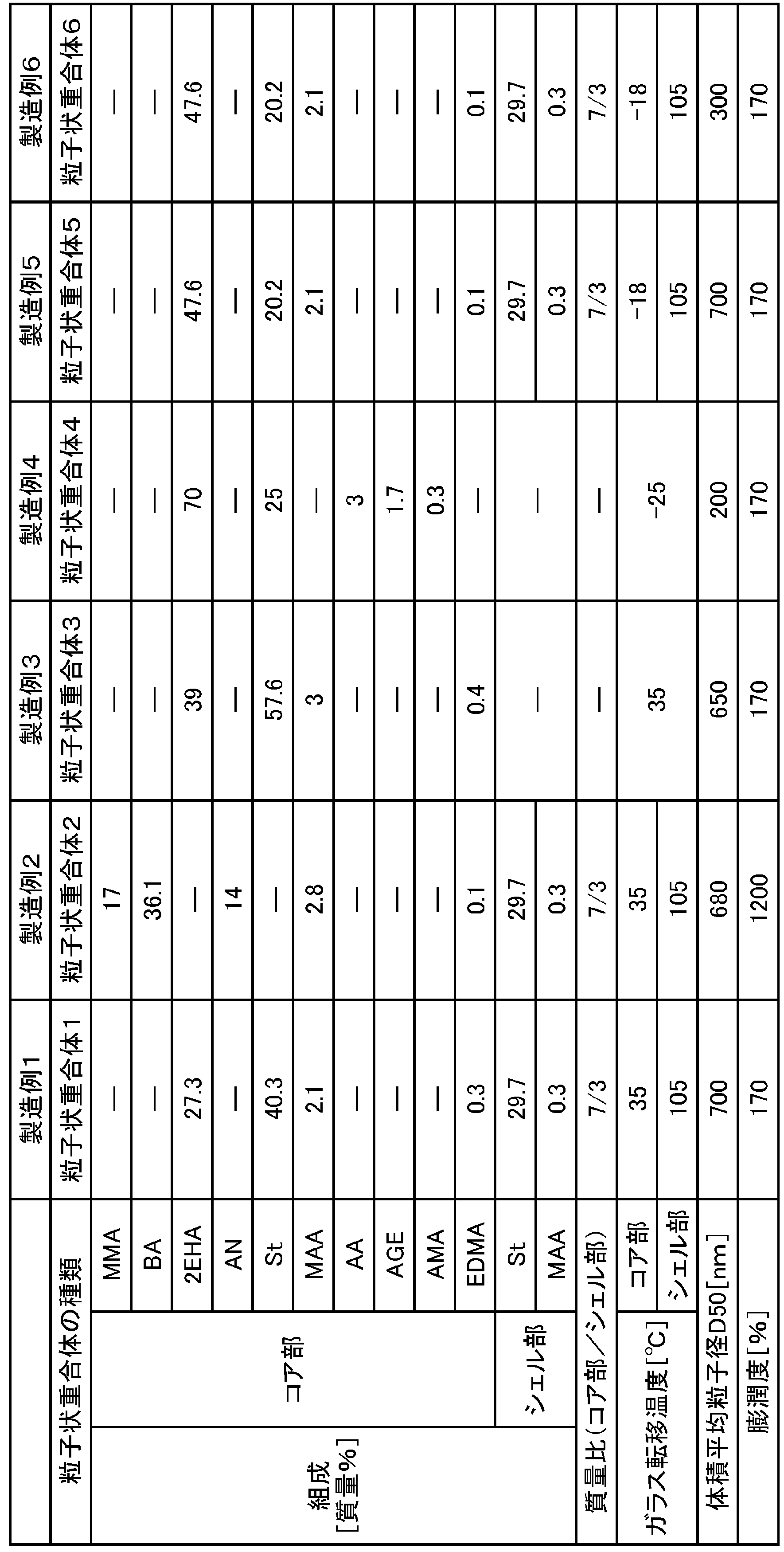
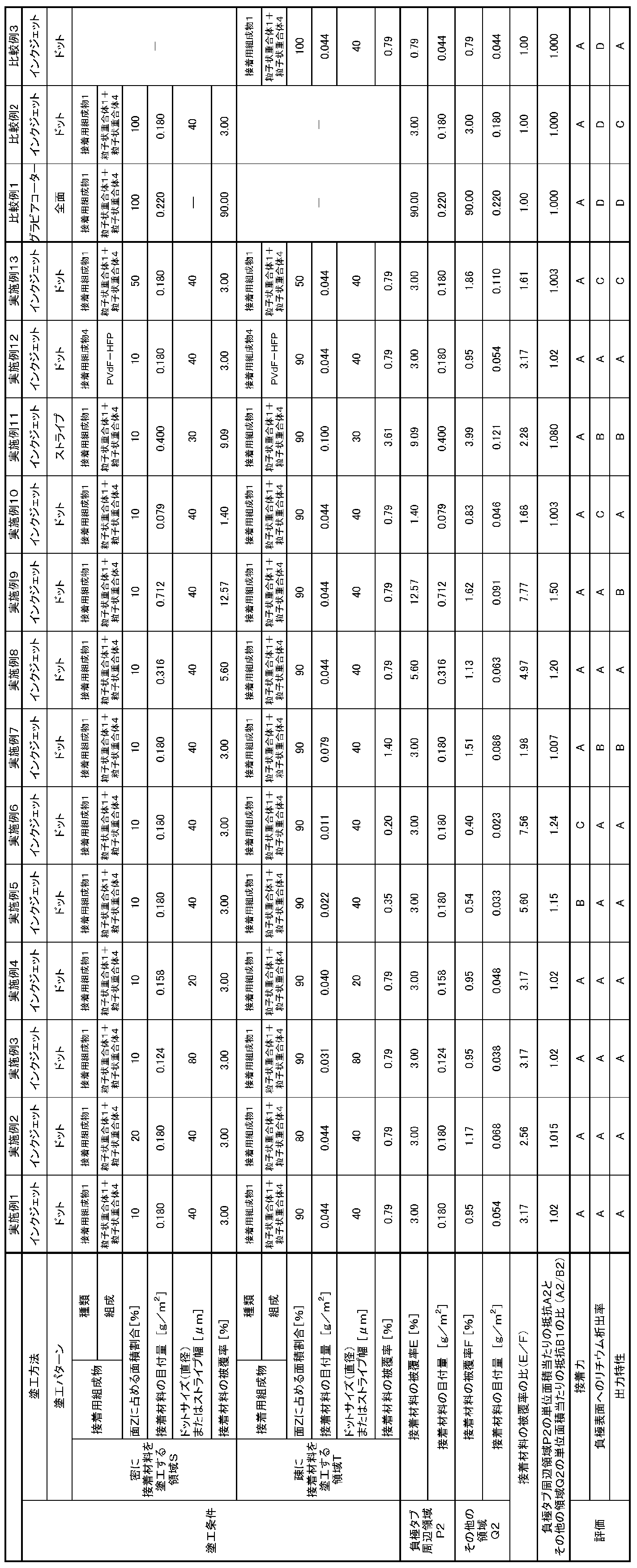


表2、3、4より、正極と、セパレータと、負極とが、この順で、積層されてなる積層体を有し、正極とセパレータとの貼り合わせ面Xおよび負極とセパレータとの貼り合わせ面Yの少なくともいずれかである面Zのうち、負極タブの接続辺と、当該接続辺から所定の距離にある線分とを一対の対辺とする長方形の領域P2の単位面積当たりの抵抗A2が、領域P2以外の領域Q2の単位面積当たりの抵抗B2よりも大きい実施例1~17の二次電池では、充電時における負極表面へのリチウム析出が抑制されていることが分かる。
一方、上記領域P2の単位面積当たりの抵抗A2が、領域P2以外の領域Q2の単位面積当たりの抵抗B2よりも大きくない比較例1~3では、二次電池の充電時における負極表面へのリチウム析出を抑制する点に劣ることが分かる。 From Tables 2, 3 and 4, the positive electrode, the separator, and the negative electrode have a laminated body in which the positive electrode, the separator, and the negative electrode are laminated in this order, and the bonding surface X between the positive electrode and the separator and the bonding surface between the negative electrode and the separator. Of the surfaces Z that are at least one of Y, the resistance A2 per unit area of the rectangular region P2 having the connection side of the negative electrode tab and the line segment at a predetermined distance from the connection side as a pair of opposite sides is It can be seen that in the secondary batteries of Examples 1 to 17, which are larger than the resistance B2 per unit area of the region Q2 other than the region P2, lithium precipitation on the negative electrode surface during charging is suppressed.
On the other hand, in Comparative Examples 1 to 3, in which the resistance A2 per unit area of the region P2 is not larger than the resistance B2 per unit area of the region Q2 other than the region P2, lithium on the negative electrode surface during charging of the secondary battery It can be seen that it is inferior in suppressing precipitation.
本発明によれば、充電時における電極表面への金属析出が抑制された二次電池を提供することができる。
According to the present invention, it is possible to provide a secondary battery in which metal precipitation on the electrode surface during charging is suppressed.
10 第一セパレータ
10A 第一セパレータ原反
20 負極
20A 負極原反
21 負極用集電体
22,23 負極合材層
24 第一端縁
25 第二端縁
26 第三端縁
27 第四端縁
28 負極タブ
30 第二セパレータ
30A 第二セパレータ原反
40 正極
41 正極用集電体
42,43 正極合材層
44 正極タブ
50 液滴
51~54 塗工機(ノズルヘッド)
55 ノズル
60 基材
61,62 圧着ローラ
70 切断機
91 搬送ローラ
92 ヒートローラ
Z 面
P1 正極タブ周辺領域
P2 負極タブ周辺領域
L1,L2 接続辺の長さ
S 密に接着材料を塗工する領域
T 疎に接着材料を塗工する領域
r ドットの半径
x,y ドットの中心間距離
l 塗工部の線幅
s 塗工部の間隔(未塗工部の線幅)
100,100A 積層体
200 重ね合わせ体
300 粒子状重合体
310 コア部
310S コア部の外表面
320 シェル部 101st separator 10A 1st separator original fabric 20 Negative electrode 20A Negative electrode original fabric 21 Negative electrode current collector 22,23 Negative electrode mixture layer 24 1st end edge 25 2nd end edge 26 3rd end edge 27 4th end edge 28 Negative electrode tab 30 Second separator 30A Second separator Original fabric 40 Positive electrode 41 Positive electrode current collector 42, 43 Positive electrode mixture layer 44 Positive electrode tab 50 Droplets 51 to 54 Coating machine (nozzle head)
55Nozzle 60 Base material 61, 62 Crimping roller 70 Cutting machine 91 Conveying roller 92 Heat roller Z surface P1 Positive electrode tab peripheral area P2 Negative electrode tab peripheral area L 1 , L 2 Connection side length S Densely coat the adhesive material Area T Area where the adhesive material is applied sparsely r Radius of dots x, y Distance between the centers of dots l Line width of the coated part s Spacing of the coated part (Line width of the unpainted part)
100, 100A Laminatedbody 200 Laminated body 300 Particle-like polymer 310 Core part 310S Outer surface of core part 320 Shell part
10A 第一セパレータ原反
20 負極
20A 負極原反
21 負極用集電体
22,23 負極合材層
24 第一端縁
25 第二端縁
26 第三端縁
27 第四端縁
28 負極タブ
30 第二セパレータ
30A 第二セパレータ原反
40 正極
41 正極用集電体
42,43 正極合材層
44 正極タブ
50 液滴
51~54 塗工機(ノズルヘッド)
55 ノズル
60 基材
61,62 圧着ローラ
70 切断機
91 搬送ローラ
92 ヒートローラ
Z 面
P1 正極タブ周辺領域
P2 負極タブ周辺領域
L1,L2 接続辺の長さ
S 密に接着材料を塗工する領域
T 疎に接着材料を塗工する領域
r ドットの半径
x,y ドットの中心間距離
l 塗工部の線幅
s 塗工部の間隔(未塗工部の線幅)
100,100A 積層体
200 重ね合わせ体
300 粒子状重合体
310 コア部
310S コア部の外表面
320 シェル部 10
55
100, 100A Laminated
Claims (9)
- 正極と、セパレータと、負極とが、この順で、積層されてなる積層体を有する二次電池であって、
前記正極と前記セパレータとの貼り合わせ面Xおよび前記負極と前記セパレータとの貼り合わせ面Yの少なくともいずれかを面Zとし、
前記正極に接続された正極タブおよび前記負極に接続された負極タブのいずれかの接続辺の長さをLとしたときに、
前記面Zのうち、前記接続辺と、前記接続辺からの距離が0.3Lである線分とを一対の対辺とする長方形の領域Pの単位面積当たりの抵抗Aが、前記領域P以外の領域Qの単位面積当たりの抵抗Bよりも大きい、二次電池。 A secondary battery having a laminated body in which a positive electrode, a separator, and a negative electrode are laminated in this order.
At least one of the bonding surface X between the positive electrode and the separator and the bonding surface Y between the negative electrode and the separator is defined as the surface Z.
When the length of the connection side of either the positive electrode tab connected to the positive electrode or the negative electrode tab connected to the negative electrode is L,
Of the surface Z, the resistance A per unit area of the rectangular region P having the connecting side and the line segment having a distance of 0.3L from the connecting side as a pair of opposite sides is other than the region P. A secondary battery that is larger than the resistance B per unit area of region Q. - 前記面Zに接着材料が存在し、
前記面Zの前記領域Pにおける前記接着材料の被覆率Eが、前記面Zの前記領域Qにおける前記接着材料の被覆率Fよりも大きい、請求項1に記載の二次電池。 Adhesive material is present on the surface Z
The secondary battery according to claim 1, wherein the coverage E of the adhesive material in the region P of the surface Z is larger than the coverage F of the adhesive material in the region Q of the surface Z. - 前記被覆率Eが1.3%以上30%以下である、請求項2に記載の二次電池。 The secondary battery according to claim 2, wherein the coverage E is 1.3% or more and 30% or less.
- 前記被覆率Fが0.5%以上0.4×E%未満である、請求項2または3に記載の二次電池。 The secondary battery according to claim 2 or 3, wherein the coverage F is 0.5% or more and less than 0.4 × E%.
- 前記面Zに接着材料が存在し、
前記接着材料が、粒子状重合体を含み、
前記粒子状重合体が、コア部と、前記コア部の外表面を部分的に覆うシェル部とを備えるコアシェル構造を有する、請求項1~4のいずれかに記載の二次電池。 Adhesive material is present on the surface Z
The adhesive material comprises a particulate polymer
The secondary battery according to any one of claims 1 to 4, wherein the particulate polymer has a core-shell structure including a core portion and a shell portion that partially covers the outer surface of the core portion. - 正極と、セパレータと、負極とが、この順で、積層されてなる積層体を有する二次電池の製造方法であって、
前記正極と前記セパレータとの貼り合わせ面Xおよび前記負極と前記セパレータとの貼り合わせ面Yの少なくともいずれかである面Zに接着材料を塗工する工程を含み、
前記正極に接続された正極タブおよび前記負極に接続された負極タブのいずれかの接続辺の長さをLとしたときに、
前記面Zのうち、前記接続辺と、前記接続辺からの距離が0.3Lである線分とを一対の対辺とする長方形の領域Pにおける前記接着材料の被覆率Eが、前記領域P以外の領域Qにおける前記接着材料の被覆率Fよりも大きい、二次電池の製造方法。 A method for manufacturing a secondary battery having a laminated body in which a positive electrode, a separator, and a negative electrode are laminated in this order.
A step of applying an adhesive material to at least one of the bonding surface X of the positive electrode and the separator and the bonding surface Y of the negative electrode and the separator is included.
When the length of the connection side of either the positive electrode tab connected to the positive electrode or the negative electrode tab connected to the negative electrode is L,
Of the surface Z, the coverage E of the adhesive material in the rectangular region P having the connecting side and the line segment having a distance of 0.3L from the connecting side as a pair of opposite sides is other than the region P. A method for manufacturing a secondary battery, which is larger than the coverage F of the adhesive material in the region Q. - 前記被覆率Eが1.3%以上30%以下である、請求項6に記載の二次電池の製造方法。 The method for manufacturing a secondary battery according to claim 6, wherein the coverage E is 1.3% or more and 30% or less.
- 前記被覆率Fが0.5%以上0.4×E%未満である、請求項6または7に記載の二次電池の製造方法。 The method for manufacturing a secondary battery according to claim 6 or 7, wherein the coverage F is 0.5% or more and less than 0.4 × E%.
- 前記接着材料が、粒子状重合体を含み、
前記粒子状重合体が、コア部と、前記コア部の外表面を部分的に覆うシェル部とを備えるコアシェル構造を有する、請求項6~8のいずれかに記載の二次電池の製造方法。 The adhesive material comprises a particulate polymer
The method for producing a secondary battery according to any one of claims 6 to 8, wherein the particulate polymer has a core-shell structure including a core portion and a shell portion that partially covers the outer surface of the core portion.
Priority Applications (5)
| Application Number | Priority Date | Filing Date | Title |
|---|---|---|---|
| US17/757,099 US20230006263A1 (en) | 2019-12-27 | 2020-12-15 | Secondary battery and method of producing same |
| JP2021567313A JPWO2021131918A1 (en) | 2019-12-27 | 2020-12-15 | |
| CN202080087103.XA CN114830397A (en) | 2019-12-27 | 2020-12-15 | Secondary battery and method for manufacturing same |
| KR1020227020200A KR20220121799A (en) | 2019-12-27 | 2020-12-15 | Secondary battery and its manufacturing method |
| EP20906089.6A EP4084171A1 (en) | 2019-12-27 | 2020-12-15 | Secondary battery and manufacturing method thereof |
Applications Claiming Priority (2)
| Application Number | Priority Date | Filing Date | Title |
|---|---|---|---|
| JP2019-239665 | 2019-12-27 | ||
| JP2019239665 | 2019-12-27 |
Publications (1)
| Publication Number | Publication Date |
|---|---|
| WO2021131918A1 true WO2021131918A1 (en) | 2021-07-01 |
Family
ID=76574500
Family Applications (1)
| Application Number | Title | Priority Date | Filing Date |
|---|---|---|---|
| PCT/JP2020/046808 WO2021131918A1 (en) | 2019-12-27 | 2020-12-15 | Secondary battery and manufacturing method thereof |
Country Status (6)
| Country | Link |
|---|---|
| US (1) | US20230006263A1 (en) |
| EP (1) | EP4084171A1 (en) |
| JP (1) | JPWO2021131918A1 (en) |
| KR (1) | KR20220121799A (en) |
| CN (1) | CN114830397A (en) |
| WO (1) | WO2021131918A1 (en) |
Cited By (1)
| Publication number | Priority date | Publication date | Assignee | Title |
|---|---|---|---|---|
| JP2022023488A (en) * | 2020-07-27 | 2022-02-08 | プライムプラネットエナジー&ソリューションズ株式会社 | Secondary battery and manufacturing method thereof |
Citations (6)
| Publication number | Priority date | Publication date | Assignee | Title |
|---|---|---|---|---|
| JP2012204303A (en) | 2011-03-28 | 2012-10-22 | Nippon Zeon Co Ltd | Electrode for secondary battery, binder for secondary battery electrode, manufacturing method and secondary battery |
| JP2013507732A (en) * | 2009-10-07 | 2013-03-04 | エスケー イノベーション カンパニー リミテッド | Battery electrode assembly and method of manufacturing the same |
| JP2013145763A (en) | 2013-04-30 | 2013-07-25 | Nippon Zeon Co Ltd | Slurry composition for secondary battery porous film, secondary battery electrode, secondary battery separator, and secondary battery |
| WO2015198530A1 (en) * | 2014-06-26 | 2015-12-30 | 日本ゼオン株式会社 | Laminate for nonaqueous secondary cell, method for producing same, and nonaqueous secondary cell |
| US20180145376A1 (en) * | 2016-11-24 | 2018-05-24 | Lg Chem, Ltd. | Electrode assembly comprising separator having insulation-enhancing part formed on edge portion of electrode |
| WO2018134961A1 (en) * | 2017-01-20 | 2018-07-26 | 日産自動車株式会社 | Method for manufacturing mono cell |
Family Cites Families (1)
| Publication number | Priority date | Publication date | Assignee | Title |
|---|---|---|---|---|
| JP6893402B2 (en) | 2015-07-24 | 2021-06-23 | 旭化成株式会社 | Separator for power storage device |
-
2020
- 2020-12-15 WO PCT/JP2020/046808 patent/WO2021131918A1/en unknown
- 2020-12-15 JP JP2021567313A patent/JPWO2021131918A1/ja active Pending
- 2020-12-15 CN CN202080087103.XA patent/CN114830397A/en active Pending
- 2020-12-15 US US17/757,099 patent/US20230006263A1/en active Pending
- 2020-12-15 EP EP20906089.6A patent/EP4084171A1/en active Pending
- 2020-12-15 KR KR1020227020200A patent/KR20220121799A/en active Search and Examination
Patent Citations (6)
| Publication number | Priority date | Publication date | Assignee | Title |
|---|---|---|---|---|
| JP2013507732A (en) * | 2009-10-07 | 2013-03-04 | エスケー イノベーション カンパニー リミテッド | Battery electrode assembly and method of manufacturing the same |
| JP2012204303A (en) | 2011-03-28 | 2012-10-22 | Nippon Zeon Co Ltd | Electrode for secondary battery, binder for secondary battery electrode, manufacturing method and secondary battery |
| JP2013145763A (en) | 2013-04-30 | 2013-07-25 | Nippon Zeon Co Ltd | Slurry composition for secondary battery porous film, secondary battery electrode, secondary battery separator, and secondary battery |
| WO2015198530A1 (en) * | 2014-06-26 | 2015-12-30 | 日本ゼオン株式会社 | Laminate for nonaqueous secondary cell, method for producing same, and nonaqueous secondary cell |
| US20180145376A1 (en) * | 2016-11-24 | 2018-05-24 | Lg Chem, Ltd. | Electrode assembly comprising separator having insulation-enhancing part formed on edge portion of electrode |
| WO2018134961A1 (en) * | 2017-01-20 | 2018-07-26 | 日産自動車株式会社 | Method for manufacturing mono cell |
Cited By (3)
| Publication number | Priority date | Publication date | Assignee | Title |
|---|---|---|---|---|
| JP2022023488A (en) * | 2020-07-27 | 2022-02-08 | プライムプラネットエナジー&ソリューションズ株式会社 | Secondary battery and manufacturing method thereof |
| JP7186747B2 (en) | 2020-07-27 | 2022-12-09 | プライムプラネットエナジー&ソリューションズ株式会社 | Secondary battery and manufacturing method thereof |
| US11923560B2 (en) | 2020-07-27 | 2024-03-05 | Prime Planet Energy & Solutions, Inc. | Secondary battery having greater adhesion between electrode plate and separator closer to electrode terminal and method of manufacturing the same |
Also Published As
| Publication number | Publication date |
|---|---|
| JPWO2021131918A1 (en) | 2021-07-01 |
| KR20220121799A (en) | 2022-09-01 |
| CN114830397A (en) | 2022-07-29 |
| US20230006263A1 (en) | 2023-01-05 |
| EP4084171A1 (en) | 2022-11-02 |
Similar Documents
| Publication | Publication Date | Title |
|---|---|---|
| JP7363777B2 (en) | Slurry for non-aqueous secondary batteries, separators for non-aqueous secondary batteries, electrodes for non-aqueous secondary batteries, laminates for non-aqueous secondary batteries, and non-aqueous secondary batteries | |
| JP7380581B2 (en) | Secondary battery and its manufacturing method | |
| JP7414003B2 (en) | Laminated body for secondary battery, secondary battery, and manufacturing method thereof | |
| US20210036375A1 (en) | Method of producing laminate for secondary battery | |
| JP6834127B2 (en) | A method for forming a functional layer for a non-aqueous secondary battery and a method for manufacturing a non-aqueous secondary battery | |
| JP7268675B2 (en) | Method for manufacturing laminate for non-aqueous secondary battery and method for manufacturing non-aqueous secondary battery | |
| WO2021131918A1 (en) | Secondary battery and manufacturing method thereof | |
| WO2021131914A1 (en) | Secondary battery and manufacturing method therefor | |
| WO2022209997A1 (en) | Composition for nonaqueous secondary battery adhesive layers, adhesive layer for nonaqueous secondary batteries and method for producing said adhesive layer for nonaqueous secondary batteries, multilayer body for nonaqueous secondary batteries and method for producing said multilayer body for nonaqueous secondary batteries, and nonaqueous secondary battery | |
| WO2021131715A1 (en) | Laminate for secondary batteries, secondary battery, and method for producing laminate for secondary batteries | |
| WO2022230621A1 (en) | Multilayer body for nonaqueous secondary batteries, bonding composition, and nonaqueous secondary battery | |
| WO2023008165A1 (en) | Multilayer body for nonaqueous secondary batteries, method for producing multilayer body for nonaqueous secondary batteries, and nonaqueous secondary battery | |
| WO2023032718A1 (en) | Composition for nonaqueous secondary battery adhesive layer, nonaqueous secondary battery adhesive layer and method for producing same, laminate for nonaqueous secondary battery and method for producing same, and nonaqueous secondary battery | |
| WO2023162605A1 (en) | Nonaqueous secondary battery adhesive layer composition, nonaqueous secondary battery adhesive layer, battery member for nonaqueous secondary battery, method for producing same, laminate for nonaqueous secondary battery, method for producing same, and nonaqueous secondary battery | |
| WO2022230908A1 (en) | Composition for nonaqueous secondary battery adhesive layer, nonaqueous secondary battery adhesive layer and method for producing same, laminate for nonaqueous secondary battery and method for producing same, and nonaqueous secondary battery |
Legal Events
| Date | Code | Title | Description |
|---|---|---|---|
| 121 | Ep: the epo has been informed by wipo that ep was designated in this application |
Ref document number: 20906089 Country of ref document: EP Kind code of ref document: A1 |
|
| ENP | Entry into the national phase |
Ref document number: 2021567313 Country of ref document: JP Kind code of ref document: A |
|
| NENP | Non-entry into the national phase |
Ref country code: DE |
|
| ENP | Entry into the national phase |
Ref document number: 2020906089 Country of ref document: EP Effective date: 20220727 |