WO2021125317A1 - 画像処理装置及び画像処理方法 - Google Patents
画像処理装置及び画像処理方法 Download PDFInfo
- Publication number
- WO2021125317A1 WO2021125317A1 PCT/JP2020/047393 JP2020047393W WO2021125317A1 WO 2021125317 A1 WO2021125317 A1 WO 2021125317A1 JP 2020047393 W JP2020047393 W JP 2020047393W WO 2021125317 A1 WO2021125317 A1 WO 2021125317A1
- Authority
- WO
- WIPO (PCT)
- Prior art keywords
- prediction
- adopted
- unit
- fixed
- image
- Prior art date
- Legal status (The legal status is an assumption and is not a legal conclusion. Google has not performed a legal analysis and makes no representation as to the accuracy of the status listed.)
- Ceased
Links
Images






























Classifications
-
- H—ELECTRICITY
- H04—ELECTRIC COMMUNICATION TECHNIQUE
- H04N—PICTORIAL COMMUNICATION, e.g. TELEVISION
- H04N19/00—Methods or arrangements for coding, decoding, compressing or decompressing digital video signals
- H04N19/70—Methods or arrangements for coding, decoding, compressing or decompressing digital video signals characterised by syntax aspects related to video coding, e.g. related to compression standards
-
- H—ELECTRICITY
- H04—ELECTRIC COMMUNICATION TECHNIQUE
- H04N—PICTORIAL COMMUNICATION, e.g. TELEVISION
- H04N19/00—Methods or arrangements for coding, decoding, compressing or decompressing digital video signals
- H04N19/50—Methods or arrangements for coding, decoding, compressing or decompressing digital video signals using predictive coding
- H04N19/593—Methods or arrangements for coding, decoding, compressing or decompressing digital video signals using predictive coding involving spatial prediction techniques
-
- H—ELECTRICITY
- H04—ELECTRIC COMMUNICATION TECHNIQUE
- H04N—PICTORIAL COMMUNICATION, e.g. TELEVISION
- H04N19/00—Methods or arrangements for coding, decoding, compressing or decompressing digital video signals
- H04N19/10—Methods or arrangements for coding, decoding, compressing or decompressing digital video signals using adaptive coding
- H04N19/102—Methods or arrangements for coding, decoding, compressing or decompressing digital video signals using adaptive coding characterised by the element, parameter or selection affected or controlled by the adaptive coding
- H04N19/103—Selection of coding mode or of prediction mode
- H04N19/11—Selection of coding mode or of prediction mode among a plurality of spatial predictive coding modes
-
- H—ELECTRICITY
- H04—ELECTRIC COMMUNICATION TECHNIQUE
- H04N—PICTORIAL COMMUNICATION, e.g. TELEVISION
- H04N19/00—Methods or arrangements for coding, decoding, compressing or decompressing digital video signals
- H04N19/10—Methods or arrangements for coding, decoding, compressing or decompressing digital video signals using adaptive coding
- H04N19/134—Methods or arrangements for coding, decoding, compressing or decompressing digital video signals using adaptive coding characterised by the element, parameter or criterion affecting or controlling the adaptive coding
- H04N19/136—Incoming video signal characteristics or properties
- H04N19/14—Coding unit complexity, e.g. amount of activity or edge presence estimation
-
- H—ELECTRICITY
- H04—ELECTRIC COMMUNICATION TECHNIQUE
- H04N—PICTORIAL COMMUNICATION, e.g. TELEVISION
- H04N19/00—Methods or arrangements for coding, decoding, compressing or decompressing digital video signals
- H04N19/10—Methods or arrangements for coding, decoding, compressing or decompressing digital video signals using adaptive coding
- H04N19/169—Methods or arrangements for coding, decoding, compressing or decompressing digital video signals using adaptive coding characterised by the coding unit, i.e. the structural portion or semantic portion of the video signal being the object or the subject of the adaptive coding
- H04N19/17—Methods or arrangements for coding, decoding, compressing or decompressing digital video signals using adaptive coding characterised by the coding unit, i.e. the structural portion or semantic portion of the video signal being the object or the subject of the adaptive coding the unit being an image region, e.g. an object
- H04N19/176—Methods or arrangements for coding, decoding, compressing or decompressing digital video signals using adaptive coding characterised by the coding unit, i.e. the structural portion or semantic portion of the video signal being the object or the subject of the adaptive coding the unit being an image region, e.g. an object the region being a block, e.g. a macroblock
Definitions
- the present technology relates to an image processing device and an image processing method, and more particularly to, for example, an image processing device and an image processing method that enable processing to be simplified.
- JVET Joint Video Experts Team
- ISO / IEC ISO/ IEC
- MIP matrix intra prediction
- the parameters of the matrix (weight matrix) obtained by parameter learning are specified, and operations are performed using the matrix (parameters).
- MIP calculation (calculation performed by MIP) is performed using the offset factor fO.
- the offset factor fO is changed according to the MipSizeId representing the matrix size of the matrix and the modeId representing the mode number of the MIP in order to improve the bit precision.
- the offset factor fO is changed according to the MipSizeId and the modeId. Therefore, the offset factor fO must be set for each combination of the MipSizeId and the modeId, which complicates the process. ..
- This technology was made in view of such a situation, and makes it possible to simplify the process.
- the first image processing apparatus of the present technology changes the pixel value set to a fixed value when performing matrix intra-prediction, which is intra-prediction using matrix calculation, for the current prediction block to be encoded.
- the current prediction is performed using the intra prediction unit that performs the matrix intra prediction using the coefficient related to the sum of the quantities and generates a prediction image of the current prediction block, and the prediction image generated by the intra prediction unit.
- It is an image processing apparatus including a coding unit that encodes a block.
- the first image processing method of the present technology is to change the pixel value set to a fixed value when performing matrix intra-prediction, which is intra-prediction using matrix calculation, for the current prediction block to be encoded.
- the current prediction is performed using the intra-prediction step of performing the matrix intra-prediction using the coefficient related to the sum of the quantities and generating the prediction image of the current prediction block, and the prediction image generated in the intra-prediction step.
- It is an image processing method including a coding step of coding a block.
- a fixed value is set when performing matrix intra-prediction, which is intra-prediction using matrix calculation, for the current prediction block to be encoded.
- the matrix intra-prediction is performed using the coefficient related to the sum of the changes in the pixel values, and the predicted image of the current prediction block is generated. Then, the current prediction block is encoded using the prediction image.
- the second image processing apparatus of the present technology sets the amount of change in the pixel value to a fixed value when performing matrix intra-prediction, which is intra-matrix prediction using matrix calculation, for the current prediction block to be decoded.
- the matrix intra-prediction is performed using the coefficient related to the sum of the above, and the intra-prediction unit that generates the prediction image of the current prediction block and the prediction image generated by the intra-prediction unit are used to generate the current prediction block.
- the second image processing method of the present technology is the amount of change in the pixel value set to a fixed value when performing matrix intra-prediction, which is an intra-prediction using matrix calculation for the current prediction block to be decoded.
- the matrix intra-prediction is performed using the coefficient related to the sum of the above, and the intra-prediction step of generating the prediction image of the current prediction block and the prediction image generated in the intra-prediction step are used to generate the current prediction block.
- This is an image processing method including a decoding step of decoding the image.
- a fixed value is set when performing matrix intra-prediction, which is intra-prediction using matrix calculation, for the current prediction block to be decoded.
- the matrix intra-prediction is performed using the coefficient related to the sum of the changes in the pixel values, and the predicted image of the current prediction block is generated. Then, the current prediction block is decoded using the prediction image.
- the image processing device may be an independent device or an internal block constituting one device.
- the image processing device can be realized by causing a computer to execute a program.
- the program can be provided by recording on a recording medium or by transmitting via a transmission medium.
- Quad-Tree Block Structure QTBT (Quad Tree Plus Binary Tree) Block Structure
- MTT Multi-type Tree Block Structure
- REF1 Recommendation ITU-T H.264 (04/2017) “Advanced video coding for generic audiovisual services”, April 2017
- REF2 Recommendation ITU-T H.265 (02/2018) “High efficiency video coding”, February 2018
- REF3 Benjamin Bross, Jianle Chen, Shan Liu, Versatile Video Coding (Draft 7), JVET-P2001-v14 (version 14 --date 2019-11-14)
- REF4 Jianle Chen, Yan Ye, Seung Hwan Kim, Algorithm description for Versatile Video Coding and Test Model 7 (VTM 7), JVET-P2002-v1 (version 1 --date 2019-11-10)
- REF5 JVET-N0217-v3: CE3: Affine linear weighted intra prediction (CE3-4.1, CE3-4.2) (version 7 --date 2019-01-17)
- REF6 JVET-M0043-v2: CE3: Affine linear weighted intra prediction (test 1.2.1, test 1.
- JVET-P0136-v2 version 3 --date 2019-10-04
- REF11 Thibaud Biatek, Adarsh K. Ramasubramonian, Geert Van der Auwera, Marta Karczewicz
- Non-CE3 simplified MIP with power-of-two offset.
- JVET-P0625-v2 version 2-date 2019-10-02
- the term "adjacent" includes not only the case where one pixel (one line) is adjacent to the current pixel of interest, but also the case where a plurality of pixels (multiple lines) are adjacent. Therefore, the adjacent pixel includes a pixel at a position of one pixel directly adjacent to the current pixel and a pixel at a position of a plurality of pixels continuously adjacent to the current pixel. Further, the adjacent block includes a block in the range of one block directly adjacent to the current block of interest, and a block in the range of a plurality of blocks continuously adjacent to the current block. Further, the adjacent block can also include a block located in the vicinity of the current block, if necessary.
- the prediction block means a block (PU (Prediction Unit)) that is a processing unit when performing intra-prediction or inter-prediction, and includes sub-blocks in the prediction block.
- PU Prediction Unit
- TU Transform Unit
- CU Coding Unit
- the orthogonal transformation block is a block that is a processing unit when performing orthogonal transformation
- the coding block is a block that is a processing unit when performing coding.
- the intra prediction mode is referred to when deriving the intra prediction mode such as the mode number when performing intra prediction, the index of the mode number, the block size of the prediction block, and the size of the subblock which is the processing unit in the prediction block. It means comprehensively the variables (parameters) to be used.
- the matrix intra prediction mode is the mode number of MIP, the index of the mode number, the type of matrix used when performing MIP calculation, the type of matrix size of the matrix used when performing MIP calculation, etc. It means comprehensively the variables (parameters) referred to when deriving the matrix intra-prediction mode.
- a parameter is a general term for data required for encoding or decoding, and is typically a bitstream syntax, parameter set, or the like. Further, the parameters include variables and the like used in the derivation process. For MIP, various data used when performing MIP calculation correspond to the parameters. For example, the offset factor fO, the shift amount sW, and the weight matrix (component) mWeight [i] [j] described in REF3 correspond to the parameters.
- Changing means changing the determined content, for example, changing the content described in the publicly known document based on the date before the filing date of the present application. Therefore, for example, a difference from the content (value, arithmetic expression, variable, etc.) described in Reference REF3 corresponds to a change.
- identification data that identifies a plurality of patterns can be set as a bitstream syntax obtained by encoding an image.
- the bitstream can contain identification data that identifies various patterns.
- the decoder that decodes the bitstream can perform processing more efficiently by parsing and referencing the identification data.
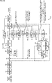
- FIG. 1 is a diagram illustrating the first MIP method.
- the first MIP method is a method for generating a predicted image of MIP proposed in Reference REF3 (JVET-P2001-v14).
- predMip [x] [y] ((( ⁇ mWeight [i] [y * predSize + x] * p [i]) + oW) >> sW) + pTemp [0] ⁇ ⁇ ⁇ (258)
- equation (258) the variable oW is calculated according to the following equation described as equation (257) in reference REF3.
- a ⁇ B and A >> B represent that A is shifted left and right by the B bit, respectively.
- PredMip [x] [y] represents the pixel (pixel value) where the horizontal position of the predicted image is x and the vertical position is y.
- the pixels of the predicted image are also called predicted pixels.
- the weight matrix mWeight [i] [j] set according to the MipSizeId and the modeId, the shift amount sW, and the offset factor fO are used. Then, MIP is performed and the pixels predMip [x] [y] of the predicted image are generated.
- p [i] represents the amount of change in the pixel (pixel value) pTemp [i] in the current prediction block.
- p [i] is the amount of change in the pixel pTemp [i] based on the pixel pTemp [0] on the upper left of the current prediction block.
- the offset factor fO is a coefficient related to the sum ⁇ p [i] of the amount of change p [i] of the pixel value.
- the shift amount sW is set according to MipSizeId and modeId according to Table 23 described in Reference REF3.
- the offset factor fO is set according to MipSizeId and modeId according to Table 24 described in Reference REF3.
- variable sW is derived using mipSizeId and modeId as specified in Table 8-5.” Is described, but “Table 8-5" is an error of "Table 23”. Further, in reference REF3, "The variable fO is derived using mipSizeId and modeId as specified in Table 8-6.” Is described, but “Table 8-6” is an error of "Table 24".
- reference REF11 JVET-P0625-v2
- fO offset factor
- the offset factor fO can be multiplied by a shift operation.
- the processing of MIP can be simplified.
- the offset factor fO is reset according to the MipSizeId and modeId as in the case of using the current Table 24. It is necessary and the processing becomes complicated.
- the first MIP method when the first MIP method is implemented by hardware, a selector for switching the offset factor fO is required, which increases the circuit scale.
- a selector for switching the offset factor fO when implementing the first MIP method by software, it is necessary to prepare a table in which the offset factor fO expressed by the power of 2 is defined and refer to that table, which reduces the processing speed. To do.
- MIP is performed using the offset factor fO set to a fixed value. That is, for example, the operations of equations (258) and (257) are changed according to the offset factor fO set to a fixed value, and the predicted image of MIP is generated according to the changed operations.
- the offset factor fO set to a fixed value as appropriate is also referred to as a fixed offset coefficient.
- the fixed offset coefficient is an offset factor fO set to a fixed value, it is a coefficient related to the sum ⁇ p [i] of the amount of change p [i] of the pixel value, like the offset factor fO.
- FIG. 2 is a diagram illustrating the second MIP method.
- the offset factor fO of the equation (257) for generating the predicted image of MIP proposed in Reference REF3 is set to the fixed offset coefficient which is a fixed value.
- the fixed value to be the fixed offset coefficient for example, a value in which the range of the weight matrix mWeight [i] [j] is set to a predetermined range can be adopted.
- the weight matrix mWeight [i] [j] changes from the value described in reference REF3.
- a value can be adopted so that the range of the weight matrix mWeight [i] [j] after the change falls within a predetermined range.
- a value represented by a power of 2 or a value represented by the sum of powers of 2 can be adopted.
- the calculation accuracy is improved when the value represented by the sum of the powers of 2 is adopted rather than the value represented by the power of 2, that is, the MIP.
- the prediction error of the prediction image can be reduced.
- the shift amount sW of Eqs. (258) and Eq. (257) for generating the predicted image of MIP proposed in Reference REF3 is further set to a fixed shift amount which is a fixed value. Can be done.
- the fixed shift amount for example, one of three (types) shift amounts sW of 5, 6 and 7 specified in Table 23 of Reference REF3 can be adopted.
- the weight matrix mWeight depends on the fixed offset coefficient and the three shift amounts sW defined in Table 23 of Reference REF3, or according to the fixed offset coefficient and the fixed shift amount. [i] [j] are changed from the values described in reference REF3.
- the predicted pixel predMip [x] [y] obtained when the offset factor fO and the shift amount sW are adopted that is, the predicted pixel predMip [x] [y] obtained according to the reference REF3 (of the predicted image of MIP). It is also called the standard predicted pixel predMip [x] [y].
- the predicted pixels obtained when the fixed offset coefficient and the fixed shift amount are adopted (hereinafter, also referred to as fixed predicted pixels), that is, the offset factors fO of the equations (258) and (257).
- the predicted pixel predMip [x] [y] obtained according to the equation in which the shift amount sW is replaced with the fixed offset coefficient and the fixed shift amount, respectively becomes a value close to the standard predicted pixel predMip [x] [y].
- the weight matrix mWeight [i] [j] described in Reference REF3 is changed according to the fixed offset coefficient and the fixed shift amount.
- the changed weight matrix mWeight [i] [j] can be contained in a range that can be represented by 7 bits of 0 to 127.
- a predicted image of MIP is generated according to an operation including the changed weight matrix mWeight [i] [j].
- the offset factor fO of Eqs. (258) and Eq. (257) and the shift amount sW are fixed regardless of the combination of MipSizeId and modeId, which simplifies MIP processing. can do.
- the selector for switching the offset factor fO and the shift amount sW becomes unnecessary, and the increase in the circuit scale can be suppressed.
- the second MIP method is implemented by software, it is not necessary to refer to Table 24 or Table 23, and the decrease in processing speed is suppressed as compared with the case of referring to Table 24 or Table 23. be able to.
- the fixed offset coefficient a value represented by a power of 2 other than 32 or a value represented by the sum of powers of 2 other than 48 and 96 can be adopted. Further, as the fixed shift amount, values other than 5, 6, and 7 can be adopted.
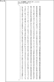
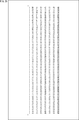
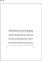
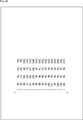
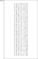
- FIG. 3 is a diagram for explaining the MIP when 48 is adopted as the fixed offset coefficient and 5 is adopted as the fixed shift amount.
- the sum sum ⁇ p [i] of the amount of change in the pixel value p [i] is calculated.
- the multiplication 48 * ( ⁇ p [i]) of the sum ⁇ p [i] of the amount of change p [i] of the pixel value and the fixed offset coefficient 48 is the shift operation (sum ⁇ 5) and (sum ⁇ 5) of the sum sum. It is performed by sum ⁇ 4) and the addition of the results of its shift operations (sum ⁇ 5) and (sum ⁇ 4).
- the variable oW in Eq. (257) is calculated.
- M represents MipSizeId
- m represents modeId
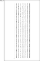
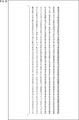
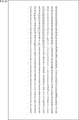
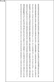
- the weight matrix mWeight [i] [j] when the fixed offset coefficient and the fixed shift amount are adopted is also referred to as a fixed weight matrix mWeight [i] [j].
- the i + 1th value from the left and the j + 1th value from the top represent the fixed weight matrix mWeight [i] [j]. The same applies to the following figures.
- the calculation is performed using the fixed offset coefficient and the fixed shift amount, and within the range where the technical effect is appropriately achieved. If there is, it can be changed as appropriate.
- the predicted image can be appropriately changed within a range in which technical effects such as ensuring a predetermined prediction accuracy or higher can be obtained.
- the approximation level means the degree to which the fixed prediction pixel predMip [x] [y] is approximated to the true value of the fixed prediction pixel predMip [x] [y] or the standard prediction pixel predMip [x] [y]. ..
- the fixed predicted pixel predMip [x] [y] means the predicted pixel (pixel value) obtained by MIP using the fixed offset coefficient and the fixed shift amount.
- the standard prediction pixel predMip [x] [y] means a prediction pixel obtained by MIP using the offset factor fO and the shift amount sW described in Reference REF3.
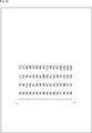
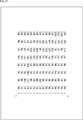
- FIG. 34 is a diagram for explaining the MIP when 96 is adopted as the fixed offset coefficient and 6 is adopted as the fixed shift amount.
- the sum sum ⁇ p [i] of the amount of change in the pixel value p [i] is calculated.
- the multiplication 96 * ( ⁇ p [i]) of the sum ⁇ p [i] of the amount of change p [i] of the pixel value and 96 which is the fixed offset coefficient is the sum shift operation (sum ⁇ 6) and ( It is performed by sum ⁇ 5) and the addition of the results of its shift operations (sum ⁇ 6) and (sum ⁇ 5).
- the variable oW in Eq. (257) is calculated.
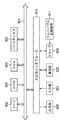
- FIG. 65 is a block diagram showing a configuration example of an embodiment of an image processing system to which the present technology is applied.
- the image processing system 10 has an image processing device as an encoder 11 and an image processing device as a decoder 51.
- the encoder 11 encodes the original image to be coded supplied to the encoder 11 and outputs a coded bit stream obtained by the coding.
- the coded bit stream is supplied to the decoder 51 via a recording medium or a transmission medium (not shown).
- the decoder 51 decodes the coded bit stream supplied to the decoder 51 and outputs the decoded image obtained by the decoding.
- FIG. 66 is a block diagram showing a configuration example of the encoder 11 of FIG. 65.
- the encoder 11 has an A / D conversion unit 21, a sorting buffer 22, a calculation unit 23, an orthogonal conversion unit 24, a quantization unit 25, a lossless coding unit 26, and a storage buffer 27. Further, the encoder 11 includes an inverse quantization unit 28, an inverse orthogonal transform unit 29, a calculation unit 30, a frame memory 32, a selection unit 33, an intra prediction unit 34, a motion prediction compensation unit 35, a prediction image selection unit 36, and a rate. It has a control unit 37. Further, the encoder 11 has a deblock filter 31a, an adaptive offset filter 41, and an ALF (adaptive loop filter) 42.
- ALF adaptive loop filter
- the encoder 11 can be configured without providing the A / D conversion unit 21.
- the sorting buffer 22 sorts the frames of the original image in the order of coding (decoding) from the display order according to the GOP (Group Of Picture), and the calculation unit 23, the intra prediction unit 34, and the motion prediction compensation unit 35. Supply to.
- GOP Group Of Picture
- the calculation unit 23 subtracts the predicted image supplied from the intra prediction unit 34 or the motion prediction compensation unit 35 via the prediction image selection unit 36 from the original image from the sorting buffer 22, and the residual obtained by the subtraction. (Predicted residual) is supplied to the orthogonal conversion unit 24.
- the orthogonal transform unit 24 performs orthogonal transform such as discrete cosine transform and Karhunen-Loève transform on the residual supplied from the arithmetic unit 23, and supplies the orthogonal transform coefficient obtained by the orthogonal transform to the quantization unit 25. To do.
- the quantization unit 25 quantizes the orthogonal transformation coefficient supplied from the orthogonal transform unit 24.
- the quantization unit 25 sets the quantization parameter based on the target value (code amount target value) of the code amount supplied from the rate control unit 37, and performs the quantization of the orthogonal transformation coefficient.
- the quantization unit 25 supplies the coded data, which is the quantized orthogonal conversion coefficient, to the lossless coding unit 26.
- the lossless coding unit 26 encodes the quantized orthogonal transformation coefficient as the coded data from the quantization unit 25 by a predetermined lossless coding method.
- the lossless coding unit 26 acquires the coding information necessary for decoding by the decoding device 170 from each block among the coding information related to the predictive coding in the encoder 11.
- the coding information for example, the prediction mode of intra-prediction or inter-prediction, motion information such as motion vector, code amount target value, quantization parameter, picture type (I, P, B), deblock filter 31a. And the filter parameters of the adaptive offset filter 41 and the like.
- the prediction mode can be acquired from the intra prediction unit 34 and the motion prediction compensation unit 35.
- the motion information can be acquired from the motion prediction compensation unit 35.
- the filter parameters of the deblock filter 31a and the adaptive offset filter 41 can be obtained from the deblock filter 31a and the adaptive offset filter 41, respectively.
- the lossless coding unit 26 uses variable length coding such as CAVLC (Context-Adaptive Variable Length Coding) or CABAC (Context-Adaptive Binary Arithmetic Coding), arithmetic coding, or other lossless coding method for the coding information.
- variable length coding such as CAVLC (Context-Adaptive Variable Length Coding) or CABAC (Context-Adaptive Binary Arithmetic Coding), arithmetic coding, or other lossless coding method for the coding information.
- a coded bit stream containing the coded and coded coded information and the coded data from the quantization unit 25 is generated and supplied to the storage buffer 27.
- the above-mentioned calculation unit 23 or lossless coding unit 26 constitutes a coding unit that encodes an image, and the processing (process) performed by the coding unit is the coding process.
- the storage buffer 27 temporarily stores the coded bit stream supplied from the lossless coding unit 26.
- the coded bit stream stored in the storage buffer 27 is read out and transmitted at a predetermined timing.
- the coded data which is the orthogonal transformation coefficient quantized in the quantization unit 25, is supplied to the lossless coding unit 26 as well as to the inverse quantization unit 28.
- the inverse quantization unit 28 dequantizes the quantized orthogonal transformation coefficient by a method corresponding to the quantization by the quantization unit 25, and the orthogonal transformation coefficient obtained by the inverse quantization is transmitted to the inverse orthogonal transform unit 29. Supply.
- the inverse orthogonal transform unit 29 converts the orthogonal transform coefficient supplied from the inverse orthogonal transform unit 28 into an orthogonal transform by a method corresponding to the orthogonal transform process by the orthogonal transform unit 24, and obtains the residual obtained as a result of the inverse orthogonal transform. , Supply to the arithmetic unit 30.
- the calculation unit 30 adds the predicted image supplied from the intra prediction unit 34 or the motion prediction compensation unit 35 via the prediction image selection unit 36 to the residual supplied from the inverse orthogonal transform unit 29, whereby the original image is added. Obtain (a part of) the decoded image obtained by decoding the image and output it.
- the decoded image output by the calculation unit 30 is supplied to the deblock filter 31a or the frame memory 32.
- the frame memory 32 temporarily stores the decoded image supplied from the calculation unit 30, the deblocking filter 31a supplied from the ALF 42, the adaptive offset filter 41, and the decoded image (filter image) to which the ALF 42 is applied. ..
- the decoded image stored in the frame memory 32 is supplied to the selection unit 33 as a reference image used for generating the predicted image at a necessary timing.
- the selection unit 33 selects the supply destination of the reference image supplied from the frame memory 32.
- the selection unit 33 supplies the reference image supplied from the frame memory 32 to the intra prediction unit 34.
- the motion prediction compensation unit 35 performs inter-prediction, the selection unit 33 supplies the reference image supplied from the frame memory 32 to the motion prediction compensation unit 35.
- the intra prediction unit 34 performs intra prediction (in-screen prediction) using the original image supplied from the sorting buffer 22 and the reference image supplied from the frame memory 32 via the selection unit 33.
- the intra prediction unit 34 selects the optimum intra prediction prediction mode based on a predetermined cost function, and transmits the prediction image generated from the reference image in the optimum intra prediction prediction mode to the prediction image selection unit 36. Supply. Further, the intra prediction unit 34 appropriately supplies the prediction mode of the intra prediction selected based on the cost function to the lossless coding unit 26 and the like.
- the motion prediction compensation unit 35 performs motion prediction using the original image supplied from the sorting buffer 22 and the reference image supplied from the frame memory 32 via the selection unit 33. Further, the motion prediction compensation unit 35 performs motion compensation according to the motion vector detected by the motion prediction, and generates a prediction image.
- the motion prediction compensation unit 35 performs inter-prediction in a plurality of inter-prediction prediction modes prepared in advance, and generates a prediction image from the reference image.
- the motion prediction compensation unit 35 selects the optimum inter-prediction prediction mode from a plurality of inter-prediction prediction modes based on a predetermined cost function. Further, the motion prediction compensation unit 35 supplies the prediction image generated in the prediction mode of the optimum inter-prediction to the prediction image selection unit 36.
- the motion prediction compensation unit 35 includes an optimum inter-prediction prediction mode selected based on the cost function, a motion vector required for decoding the coded data encoded in the inter-prediction prediction mode, and the like.
- the motion information and the like of the above are supplied to the reversible coding unit 26.
- the prediction image selection unit 36 selects the supply source of the prediction image to be supplied to the calculation unit 23 and the calculation unit 30 from the intra prediction unit 34 and the motion prediction compensation unit 35, and is supplied from the selected supply source.
- the predicted image is supplied to the calculation unit 23 and the calculation unit 30.
- the rate control unit 37 controls the rate of the quantization operation of the quantization unit 25 based on the code amount of the coded bit stream stored in the storage buffer 27 so that overflow or underflow does not occur. That is, the rate control unit 37 sets a target code amount of the coded bit stream and supplies it to the quantization unit 25 so that overflow and underflow of the storage buffer 27 do not occur.
- the deblock filter 31a applies the deblock filter to the decoded image from the calculation unit 30 as necessary, and the deblock filter is applied to the decoded image (filter image), or the deblock filter is not applied.
- the decoded image is supplied to the adaptive offset filter 41.
- the adaptive offset filter 41 applies the adaptive offset filter to the decoded image from the deblock filter 31a as necessary, and the decoded image (filter image) to which the adaptive offset filter is applied, or the adaptive offset filter is applied. No decoded image is supplied to ALF42.
- the ALF 42 applies the ALF to the decoded image from the adaptive offset filter 41 as necessary, and supplies the decoded image to which the ALF is applied or the decoded image to which the ALF is not applied to the frame memory 32.
- FIG. 67 is a flowchart illustrating an example of coding processing of the encoder 11 of FIG. 66.
- each step of the coding process shown in FIG. 67 is an order for convenience of explanation, and each step of the actual coding process is performed in a necessary order in parallel as appropriate. The same applies to the processing described later.
- step S11 the A / D conversion unit 21 A / D-converts the original image and supplies it to the sorting buffer 22, and the process proceeds to step S12.
- step S12 the sorting buffer 22 stores the original images from the A / D conversion unit 21, sorts them in the coding order, and outputs them, and the process proceeds to step S13.
- step S13 the intra prediction unit 34 makes an intra prediction (intra prediction step), and the process proceeds to step S14.
- step S14 the motion prediction compensation unit 35 performs inter-prediction for motion prediction and motion compensation, and the process proceeds to step S15.
- step S15 the prediction image selection unit 36 determines the optimum prediction mode based on each cost function obtained by the intra prediction unit 34 and the motion prediction compensation unit 35. Then, the prediction image selection unit 36 selects and outputs a prediction image of the optimum prediction mode from the prediction image generated by the intra prediction unit 34 and the prediction image generated by the motion prediction compensation unit 35, and outputs the prediction image. The process proceeds from step S15 to step S16.
- step S16 the calculation unit 23 calculates the residual between the target image to be encoded, which is the original image output by the sorting buffer 22, and the prediction image output by the prediction image selection unit 36, and the orthogonal transformation unit 24 calculates the residual.
- the process proceeds to step S17.
- step S17 the orthogonal transform unit 24 orthogonally transforms the residual from the arithmetic unit 23, supplies the orthogonal transform coefficient obtained as a result to the quantization unit 25, and the process proceeds to step S18.
- step S18 the quantization unit 25 quantizes the orthogonal conversion coefficient from the orthogonal conversion unit 24, and supplies the quantization coefficient obtained by the quantization to the reversible coding unit 26 and the inverse quantization unit 28.
- the process proceeds to step S19.
- step S19 the inverse quantization unit 28 inversely quantizes the quantization coefficient from the quantization unit 25, supplies the orthogonal conversion coefficient obtained as a result to the inverse orthogonal conversion unit 29, and the process proceeds to step S20. move on.
- step S20 the inverse orthogonal transform unit 29 reverse-orthogonally transforms the orthogonal transform coefficient from the inverse quantization unit 28, supplies the residual obtained as a result to the arithmetic unit 30, and the process proceeds to step S21. ..
- step S21 the calculation unit 30 adds the residual from the inverse orthogonal transform unit 29 and the prediction image output by the prediction image selection unit 36, and the calculation unit 23 is the target of the residual calculation. Generate a decoded image corresponding to the image.
- the calculation unit 30 supplies the decoded image to the deblock filter 31a, and the process proceeds from step S21 to step S22.
- step S22 the deblock filter 31a applies the deblock filter to the decoded image from the calculation unit 30, supplies the filter image obtained as a result to the adaptive offset filter 41, and the process proceeds to step S23. ..
- step S23 the adaptive offset filter 41 applies the adaptive offset filter to the filter image from the deblock filter 31a, supplies the filter image obtained as a result to the ALF 42, and the process proceeds to step S24.
- step S24 ALF 42 applies ALF to the filter image from the adaptive offset filter 41, supplies the filter image obtained as a result to the frame memory 32, and the process proceeds to step S25.
- step S25 the frame memory 32 stores the filter image supplied from the ALF 42, and the process proceeds to step S26.
- the filter image stored in the frame memory 32 is used as a reference image from which the predicted image is generated in steps S13 and S14.
- the lossless coding unit 26 encodes the coded data which is the quantization coefficient from the quantization unit 25, and generates a coded bit stream including the coded data. Further, the lossless coding unit 26 includes the quantization parameters used for the quantization in the quantization unit 25, the prediction mode obtained by the intra prediction in the intra prediction unit 34, and the inter prediction in the motion prediction compensation unit 35. If necessary, the coding information such as the prediction mode and motion information obtained in 1 and the filter parameters of the lossless filter 31a and the adaptive offset filter 41 is encoded and included in the encoded bit stream.
- the lossless coding unit 26 supplies the coded bit stream to the storage buffer 27, and the process proceeds from step S26 to step S27.
- step S27 the storage buffer 27 stores the coded bit stream from the lossless coding unit 26, and the process proceeds to step S28.
- the coded bit stream stored in the storage buffer 27 is appropriately read and transmitted.
- step S28 the rate control unit 37 determines the quantum of the quantization unit 25 so that overflow or underflow does not occur based on the code amount (generated code amount) of the coded bit stream stored in the storage buffer 27.
- the rate of the conversion operation is controlled, and the coding process ends.
- FIG. 68 is a block diagram showing a detailed configuration example of the decoder 51 of FIG. 65.
- the decoder 51 includes a storage buffer 61, a reversible decoding unit 62, an inverse quantization unit 63, an inverse orthogonal conversion unit 64, a calculation unit 65, a sorting buffer 67, and a D / A conversion unit 68. Further, the decoder 51 includes a frame memory 69, a selection unit 70, an intra prediction unit 71, a motion prediction compensation unit 72, and a selection unit 73. The decoder 51 also includes a deblock filter 31b, an adaptive offset filter 81, and an ALF 82.
- the storage buffer 61 temporarily stores the coded bit stream transmitted from the encoder 11 and supplies the coded bit stream to the reversible decoding unit 62 at a predetermined timing.
- the lossless decoding unit 62 receives the coded bit stream from the storage buffer 61 and decodes it by a method corresponding to the coding method of the lossless coding unit 26 of FIG.
- the lossless decoding unit 62 supplies the quantization coefficient as the coding data included in the decoding result of the coded bit stream to the inverse quantization unit 63.
- the reversible decoding unit 62 has a function of performing parsing.
- the reversible decoding unit 62 parses the necessary coding information included in the decoding result of the coded bit stream, and supplies the coding information to the intra prediction unit 71, the motion prediction compensation unit 72, the deblock filter 31b, and the adaptive offset filter. 81 Supply to other necessary blocks.
- the inverse quantization unit 63 dequantizes the quantization coefficient as the coded data from the reversible decoding unit 62 by a method corresponding to the quantization method of the quantization unit 25 of FIG. 66, and is obtained by the inverse quantization.
- the orthogonal conversion coefficient is supplied to the inverse orthogonal conversion unit 64.
- the inverse orthogonal transform unit 64 reverse-orthogonally transforms the orthogonal transform coefficient supplied from the inverse quantization unit 63 by a method corresponding to the orthogonal transform method of the orthogonal transform unit 24 of FIG. 66, and obtains a residual obtained as a result. It is supplied to the arithmetic unit 65.
- the prediction image is supplied from the intra prediction unit 71 or the motion prediction compensation unit 72 via the selection unit 73.
- the calculation unit 65 adds the residual from the inverse orthogonal transform unit 64 and the predicted image from the selection unit 73 to generate a decoded image and supplies it to the deblock filter 31b.
- the above-mentioned reversible decoding unit 62 or calculation unit 65 constitutes a decoding unit for decoding an image, and the process (process) performed by the decoding unit is the decoding process.
- the sorting buffer 67 temporarily stores the decoded images supplied from the ALF 82, sorts the frames (pictures) of the decoded images in the order of encoding (decoding) order, and supplies them to the D / A conversion unit 68. ..
- the decoder 51 can be configured without providing the D / A conversion unit 68.
- the frame memory 69 temporarily stores the decoded image supplied from the ALF 82. Further, the frame memory 69 uses the decoded image as a reference image to be used for generating the predicted image at a predetermined timing or based on an external request of the intra prediction unit 71, the motion prediction compensation unit 72, or the like, and the selection unit 70. Supply to.
- the selection unit 70 selects the supply destination of the reference image supplied from the frame memory 69.
- the selection unit 70 supplies the reference image supplied from the frame memory 69 to the intra prediction unit 71. Further, when decoding the image encoded by the inter-prediction, the selection unit 70 supplies the reference image supplied from the frame memory 69 to the motion prediction compensation unit 72.
- the intra prediction unit 71 uses a reference image supplied from the frame memory 69 via the selection unit 70 according to the prediction mode included in the coding information supplied from the reversible decoding unit 62, and the intra prediction unit 34 of FIG. Make the same intra-prediction as. Then, the intra prediction unit 71 supplies the prediction image obtained by the intra prediction to the selection unit 73.
- the motion prediction compensation unit 72 is supplied from the frame memory 69 via the selection unit 70 in the same manner as the motion prediction compensation unit 35 of FIG. 66 according to the prediction mode included in the coding information supplied from the reversible decoding unit 62. Inter-prediction is performed using the reference image. The inter-prediction is performed by using motion information or the like included in the coding information supplied from the reversible decoding unit 62 as necessary.
- the motion prediction compensation unit 72 supplies the prediction image obtained by the inter-prediction to the selection unit 73.
- the selection unit 73 selects the prediction image supplied from the intra prediction unit 71 or the prediction image supplied from the motion prediction compensation unit 72, and supplies the prediction image to the calculation unit 65.
- the deblock filter 31b applies the deblock filter to the decoded image from the calculation unit 65 according to the filter parameters included in the coding information supplied from the reversible decoding unit 62.
- the deblock filter 31b supplies a decoded image (filter image) to which the deblock filter is applied or a decoded image to which the deblock filter is not applied to the adaptive offset filter 81.
- the adaptive offset filter 81 applies the adaptive offset filter to the decoded image from the deblock filter 31b as necessary according to the filter parameters included in the coding information supplied from the reversible decoding unit 62.
- the adaptive offset filter 81 supplies the decoded image (filter image) to which the adaptive offset filter is applied or the decoded image to which the adaptive offset filter is not applied to the ALF 82.
- the ALF 82 applies ALF to the decoded image from the adaptive offset filter 81 as necessary, and applies the decoded image to which ALF is applied or the decoded image to which ALF is not applied to the sorting buffer 67 and the frame memory 69. Supply to.
- FIG. 69 is a flowchart illustrating an example of decoding processing of the decoder 51 of FIG. 68.
- step S51 the storage buffer 61 temporarily stores the coded bit stream transmitted from the encoder 11 and supplies it to the reversible decoding unit 62 as appropriate, and the process proceeds to step S52.
- step S52 the reversible decoding unit 62 receives and decodes the coded bit stream supplied from the storage buffer 61, and dequantizes the quantization coefficient as the coded data included in the decoding result of the coded bit stream. It is supplied to the unit 63.
- the reversible decoding unit 62 parses the coding information included in the decoding result of the coded bit stream. Then, the reversible decoding unit 62 supplies the necessary coding information to the intra prediction unit 71, the motion prediction compensation unit 72, the deblock filter 31b, the adaptive offset filter 81, and other necessary blocks.
- step S52 the process proceeds from step S52 to step S53, and the intra prediction unit 71 or the motion prediction compensation unit 72 is supplied from the frame memory 69 via the selection unit 70 and the reversible decoding unit 62.
- Intra-prediction or inter-prediction to generate a prediction image is performed according to the coded information (intra-prediction step or inter-prediction step).
- the intra prediction unit 71 or the motion prediction compensation unit 72 supplies the prediction image obtained by the intra prediction or the inter prediction to the selection unit 73, and the process proceeds from step S53 to step S54.
- step S54 the selection unit 73 selects the prediction image supplied from the intra prediction unit 71 or the motion prediction compensation unit 72, supplies the prediction image to the calculation unit 65, and the process proceeds to step S55.
- step S55 the inverse quantization unit 63 inversely quantizes the quantization coefficient from the reversible decoding unit 62, supplies the orthogonal conversion coefficient obtained as a result to the inverse orthogonal transformation unit 64, and the process proceeds to step S56. move on.
- step S56 the inverse orthogonal transform unit 64 reverse-orthogonally transforms the orthogonal transform coefficient from the inverse quantization unit 63, supplies the residual obtained as a result to the arithmetic unit 65, and the process proceeds to step S57. ..
- step S57 the calculation unit 65 generates a decoded image by adding the residual from the inverse orthogonal transform unit 64 and the predicted image from the selection unit 73. Then, the calculation unit 65 supplies the decoded image to the deblock filter 31b, and the process proceeds from step S57 to step S58.
- step S58 the deblock filter 31b applies the deblock filter to the decoded image from the arithmetic unit 65 according to the filter parameters included in the coding information supplied from the reversible decoding unit 62.
- the deblock filter 31b supplies the filter image obtained as a result of applying the deblock filter to the adaptive offset filter 81, and the process proceeds from step S58 to step S59.
- step S59 the adaptive offset filter 81 applies the adaptive offset filter to the filter image from the deblock filter 31b according to the filter parameters included in the coding information supplied from the reversible decoding unit 62.
- the adaptive offset filter 81 supplies the filter image obtained as a result of applying the adaptive offset filter to the ALF 82, and the process proceeds from step S59 to step S60.
- the ALF 82 applies the ALF to the filter image from the adaptive offset filter 81, supplies the filter image obtained as a result to the sorting buffer 67 and the frame memory 69, and the process proceeds to step S61.
- step S61 the frame memory 69 temporarily stores the filter image supplied from ALF82, and the process proceeds to step S62.
- the filter image (decoded image) stored in the frame memory 69 is used as a reference image from which the predicted image is generated in the intra-prediction or inter-prediction in step S53.
- step S62 the sorting buffer 67 sorts the filter images supplied from ALF82 in the display order and supplies them to the D / A conversion unit 68, and the process proceeds to step S63.
- step S63 the D / A conversion unit 68 D / A-converts the filter image from the sorting buffer 67, and the decoding process ends.
- the filter image (decoded image) after D / A conversion is output and displayed on a display (not shown).
- the intra prediction performed by the intra prediction unit 34 of FIG. 66 and the intra prediction unit 71 of FIG. 68 includes MIP.
- the generation of the prediction image of MIP can be performed by the second MIP method.
- This technology can be applied to any image coding / decoding method. That is, as long as it does not contradict the above-mentioned technology, the specifications of various processes related to image coding / decoding such as conversion (inverse transformation), quantization (inverse quantization), coding (decoding), and prediction are arbitrary. It is not limited to the example. In addition, some of these processes may be omitted as long as they do not contradict the present technology described above.
- a "block” (not a block indicating a processing unit) used in the description as a partial area of an image (picture) or a processing unit indicates an arbitrary partial area in the picture unless otherwise specified. Its size, shape, characteristics, etc. are not limited.
- “block” includes TB (Transform Block), TU (Transform Unit), PB (Prediction Block), PU (Prediction Unit), SCU (Smallest Coding Unit), CU ( Includes any partial area (processing unit) such as Coding Unit), LCU (Largest Coding Unit), CTB (Coding Tree Block), CTU (Coding Tree Unit), conversion block, subblock, macroblock, tile, or slice. It shall be.
- the data unit in which the various information described above is set and the data unit targeted by the various processes are arbitrary and are not limited to the above-mentioned example.
- these information and processes are TU (Transform Unit), TB (Transform Block), PU (Prediction Unit), PB (Prediction Block), CU (Coding Unit), LCU (Largest Coding Unit), and subblock, respectively.
- Blocks, tiles, slices, pictures, sequences, or components, or data in those data units may be targeted.
- this data unit can be set for each information or process, and it is not necessary that the data unit of all the information or process is unified.
- the storage location of these information is arbitrary, and may be stored in the header, parameter set, or the like of the above-mentioned data unit. Further, it may be stored in a plurality of places.
- control information related to the present technology described above may be transmitted from the coding side to the decoding side.
- control information for example, enabled_flag
- control information indicating an object to which the present technology is applied (or an object to which the present technology is not applied) may be transmitted.
- control information that specifies the block size (upper limit, lower limit, or both) to which the present technology is applied (or permission or prohibition of application), a frame, a component, a layer, or the like may be transmitted.
- the block size may be specified directly, but also the block size may be specified indirectly.
- the block size may be specified using identification data that identifies the size.
- the block size may be specified by the ratio or difference with the size of the reference block (for example, LCU, SCU, etc.).
- the designation of the block size also includes the designation of the range of the block size (for example, the designation of the range of the allowable block size).
- identification data is information for identifying a plurality of states, and includes “flag” and other names. Further, the “identification data” includes not only information used for identifying two states of true (1) or false (0), but also information capable of identifying three or more states. Therefore, the value that can be taken by this "identification data” may be, for example, 2 values of 1/0 or 3 or more values. That is, the number of bits constituting this "identification data” is arbitrary, and may be 1 bit or a plurality of bits. Further, the identification data is assumed to include not only the identification data in the bit stream but also the difference information of the identification data with respect to a certain reference information in the bit stream. "Data" includes not only the information but also the difference information with respect to the reference information.
- various information (metadata, etc.) regarding the coded data may be transmitted or recorded in any form as long as it is associated with the coded data.
- the term "associate" means, for example, to make the other data available (linkable) when processing one data. That is, the data associated with each other may be combined as one data or may be individual data.
- the information associated with the coded data (image) may be transmitted on a transmission path different from the coded data (image).
- the information associated with the coded data (image) may be recorded on a recording medium (or another recording area of the same recording medium) different from the coded data (image). Good.
- this "association" may be a part of the data, not the entire data.
- the image and the information corresponding to the image may be associated with each other in an arbitrary unit such as a plurality of frames, one frame, or a part within the frame.
- This technology provides a device or any configuration that constitutes a system, for example, a processor as a system LSI (Large Scale Integration), a module that uses a plurality of processors, a unit that uses a plurality of modules, and other functions in the unit. It can also be implemented as an added set or the like (that is, a part of the configuration of the device).
- LSI Large Scale Integration
- FIG. 70 is a block diagram showing a configuration example of an embodiment of a computer in which a program for executing all or a part of the above-mentioned series of processes is installed.
- the program can be recorded in advance on the hard disk 905 or ROM 903 as a recording medium built in the computer.
- the program can be stored (recorded) in the removable recording medium 911 driven by the drive 909.
- a removable recording medium 911 can be provided as so-called package software.
- examples of the removable recording medium 911 include a flexible disc, a CD-ROM (Compact Disc Read Only Memory), an MO (Magneto Optical) disc, a DVD (Digital Versatile Disc), a magnetic disc, and a semiconductor memory.
- the program can be installed on the computer from the removable recording medium 911 as described above, or can be downloaded to the computer via a communication network or a broadcasting network and installed on the built-in hard disk 905. That is, for example, the program transfers wirelessly from a download site to a computer via an artificial satellite for digital satellite broadcasting, or transfers to a computer by wire via a network such as LAN (Local Area Network) or the Internet. be able to.
- LAN Local Area Network
- the computer has a built-in CPU (Central Processing Unit) 902, and the input / output interface 910 is connected to the CPU 902 via the bus 901.
- CPU Central Processing Unit
- the CPU 902 executes a program stored in the ROM (Read Only Memory) 903 accordingly. .. Alternatively, the CPU 902 loads the program stored in the hard disk 905 into the RAM (Random Access Memory) 904 and executes it.
- ROM Read Only Memory
- the CPU 902 performs processing according to the above-mentioned flowchart or processing performed according to the above-mentioned block diagram configuration. Then, the CPU 902 outputs the processing result from the output unit 906, transmits it from the communication unit 908, and further records it on the hard disk 905, if necessary, via the input / output interface 910.
- the input unit 907 is composed of a keyboard, a mouse, a microphone, and the like. Further, the output unit 906 is composed of an LCD (Liquid Crystal Display), a speaker, or the like.
- LCD Liquid Crystal Display
- the processing performed by the computer according to the program does not necessarily have to be performed in chronological order in the order described as the flowchart. That is, the processing performed by the computer according to the program also includes processing executed in parallel or individually (for example, parallel processing or processing by an object).
- the program may be processed by one computer (processor) or may be distributed processed by a plurality of computers. Further, the program may be transferred to a distant computer and executed.
- the system means a set of a plurality of components (devices, modules (parts), etc.), and it does not matter whether all the components are in the same housing. Therefore, a plurality of devices housed in separate housings and connected via a network, and a device in which a plurality of modules are housed in one housing are both systems. ..
- this technology can have a cloud computing configuration in which one function is shared by a plurality of devices via a network and jointly processed.
- each step described in the above flowchart can be executed by one device or shared by a plurality of devices.
- one step includes a plurality of processes
- the plurality of processes included in the one step can be executed by one device or shared by a plurality of devices.
Landscapes
- Engineering & Computer Science (AREA)
- Multimedia (AREA)
- Signal Processing (AREA)
- Compression Or Coding Systems Of Tv Signals (AREA)
Priority Applications (5)
| Application Number | Priority Date | Filing Date | Title |
|---|---|---|---|
| JP2021565675A JPWO2021125317A1 (https=) | 2019-12-20 | 2020-12-18 | |
| US17/784,667 US12457360B2 (en) | 2019-12-20 | 2020-12-18 | Image processing device and image processing method |
| CN202080086277.4A CN114930842A (zh) | 2019-12-20 | 2020-12-18 | 图像处理装置和图像处理方法 |
| KR1020227019921A KR20220113708A (ko) | 2019-12-20 | 2020-12-18 | 화상 처리 장치 및 화상 처리 방법 |
| EP20900799.6A EP4054193A4 (en) | 2019-12-20 | 2020-12-18 | IMAGE PROCESSING DEVICE AND IMAGE PROCESSING METHOD |
Applications Claiming Priority (2)
| Application Number | Priority Date | Filing Date | Title |
|---|---|---|---|
| US201962951177P | 2019-12-20 | 2019-12-20 | |
| US62/951,177 | 2019-12-20 |
Publications (1)
| Publication Number | Publication Date |
|---|---|
| WO2021125317A1 true WO2021125317A1 (ja) | 2021-06-24 |
Family
ID=76478317
Family Applications (1)
| Application Number | Title | Priority Date | Filing Date |
|---|---|---|---|
| PCT/JP2020/047393 Ceased WO2021125317A1 (ja) | 2019-12-20 | 2020-12-18 | 画像処理装置及び画像処理方法 |
Country Status (7)
| Country | Link |
|---|---|
| US (1) | US12457360B2 (https=) |
| EP (1) | EP4054193A4 (https=) |
| JP (1) | JPWO2021125317A1 (https=) |
| KR (1) | KR20220113708A (https=) |
| CN (1) | CN114930842A (https=) |
| TW (1) | TW202130178A (https=) |
| WO (1) | WO2021125317A1 (https=) |
Cited By (1)
| Publication number | Priority date | Publication date | Assignee | Title |
|---|---|---|---|---|
| EP3989578A4 (en) * | 2019-06-19 | 2022-08-17 | Sony Group Corporation | IMAGE PROCESSING DEVICE AND IMAGE PROCESSING METHOD |
Family Cites Families (6)
| Publication number | Priority date | Publication date | Assignee | Title |
|---|---|---|---|---|
| KR20120012385A (ko) * | 2010-07-31 | 2012-02-09 | 오수미 | 인트라 예측 부호화 장치 |
| JP2015080002A (ja) * | 2012-01-19 | 2015-04-23 | 三菱電機株式会社 | 動画像符号化装置、動画像復号装置、動画像符号化方法及び動画像復号方法 |
| JP6711353B2 (ja) | 2015-06-05 | 2020-06-17 | ソニー株式会社 | 画像処理装置および画像処理方法 |
| TW202437459A (zh) | 2018-12-07 | 2024-09-16 | 美商蘭姆研究公司 | 用於具有多工加熱器陣列之靜電卡盤的長壽命延伸溫度範圍嵌入式二極體設計 |
| CN112616057B (zh) | 2019-10-04 | 2024-08-23 | Oppo广东移动通信有限公司 | 图像预测方法、编码器、解码器以及存储介质 |
| EP4074045B1 (en) * | 2019-12-10 | 2026-04-15 | Guangdong Oppo Mobile Telecommunications Corp., Ltd. | Methods for encoding and decoding pictures and associated apparatus and systems |
-
2020
- 2020-12-18 EP EP20900799.6A patent/EP4054193A4/en active Pending
- 2020-12-18 JP JP2021565675A patent/JPWO2021125317A1/ja active Pending
- 2020-12-18 KR KR1020227019921A patent/KR20220113708A/ko not_active Withdrawn
- 2020-12-18 CN CN202080086277.4A patent/CN114930842A/zh active Pending
- 2020-12-18 TW TW109144936A patent/TW202130178A/zh unknown
- 2020-12-18 US US17/784,667 patent/US12457360B2/en active Active
- 2020-12-18 WO PCT/JP2020/047393 patent/WO2021125317A1/ja not_active Ceased
Non-Patent Citations (14)
| Title |
|---|
| "Advanced video coding for generic audiovisual services", RECOMMENDATION ITU-T H.264 (04/2017, April 2017 (2017-04-01) |
| "High efficiency video coding", RECOMMENDATION ITU-T H.265 (02/2018, February 2018 (2018-02-01) |
| BENJAMIN BROSSJIANLE CHENSHAN LIU, VERSATILE VIDEO CODING (DRAFT 7), JVET-P2001-VL4, 14 November 2019 (2019-11-14) |
| BIATEK, THIBAUD ET AL.: "Non-CE3: simplified MIP with power-of-two offset", JVET-P0625-V2, JOINT VIDEO EXPERTS TEAM (JVET), 2 October 2019 (2019-10-02), XP030218185 * |
| HUO, JUNYAN ET AL.: "Non-CE3: MIP Simplification", JVET-P0136-V2, , JOINT VIDEO EXPERTS TEAM (JVET), 4 October 2019 (2019-10-04), XP030216337 * |
| HUO, JUNYAN ET AL.: "On fixed sW and fO in MIP", JVET-Q0450-V2, JOINT VIDEO EXPERTS TEAM (JVET), 8 January 2020 (2020-01-08), XP030223548 * |
| JIANLE CHENYAN YESEUNG HWAN KIM, ALGORITHM DESCRIPTION FOR VERSATILE VIDEO CODING AND TEST MODEL 7 (VTM 7), JVET-P2002-VL, 10 November 2019 (2019-11-10) |
| JUNYAN HUOHAIXIN WANGYU SUNYANZHUO MASHUAI WANFUZHENG YANGYUANFANG YUYANG LIU: "Non-CE3: MIP simplification", JVET-P0136-V2 (VERSION 3 - DATE, 4 October 2019 (2019-10-04) |
| JVET-M0043-V2: CE3: AFFINE LINEAR WEIGHTED INTRA PREDICTION, 9 January 2019 (2019-01-09) |
| JVET-N0217-V3: CE3: AFFINE LINEAR WEIGHTED INTRA PREDICTION (CE3-4.1, CE3-4.2, 17 January 2019 (2019-01-17) |
| KENJI KONDOMASARU IKEDATERUHIKO SUZUKIJUNYAN HUOYANZHUO MAFUZHENG YANSHUAI WANYUANFANG YU, CE3-2: ON ROUNDING SHIFT OF MIP, JVET-P0056-V3, 3 October 2019 (2019-10-03) |
| PFAFF, JONATHAN ET AL.: "MIP with constant shifts and offsets", JVET-Q0446-V2, JOINT VIDEO EXPERTS TEAM (JVET), 12 January 2020 (2020-01-12), XP030223539 * |
| See also references of EP4054193A4 |
| THIBAUD BIATEKADARSH K: "Ramasubramonian, Geert Van der Auwera, Marta Karczewicz, Non-CE3: simplified MIP with power-of-two offset", JVET-P0625-V2, 2 October 2019 (2019-10-02) |
Cited By (1)
| Publication number | Priority date | Publication date | Assignee | Title |
|---|---|---|---|---|
| EP3989578A4 (en) * | 2019-06-19 | 2022-08-17 | Sony Group Corporation | IMAGE PROCESSING DEVICE AND IMAGE PROCESSING METHOD |
Also Published As
| Publication number | Publication date |
|---|---|
| CN114930842A (zh) | 2022-08-19 |
| US20230009580A1 (en) | 2023-01-12 |
| EP4054193A1 (en) | 2022-09-07 |
| EP4054193A4 (en) | 2023-01-25 |
| US12457360B2 (en) | 2025-10-28 |
| TW202130178A (zh) | 2021-08-01 |
| JPWO2021125317A1 (https=) | 2021-06-24 |
| KR20220113708A (ko) | 2022-08-16 |
Similar Documents
| Publication | Publication Date | Title |
|---|---|---|
| JP7771300B2 (ja) | イントラ予測のためのエンコーダ、デコーダおよび対応する方法 | |
| KR101677406B1 (ko) | 차세대 비디오용 비디오 코덱 아키텍처 | |
| AU2011277214B2 (en) | Method and apparatus for encoding and decoding image through intra prediction | |
| JP7666711B2 (ja) | 画像処理装置及び画像処理方法 | |
| KR20220030999A (ko) | 스케일링에 기초하는 개선된 변환을 갖는 인코더, 디코더, 방법 및 컴퓨터 프로그램 | |
| CN103748875A (zh) | 用于应用基于分区的滤波器的视频译码的方法和装置和存储媒体 | |
| JP7683775B2 (ja) | 画像処理装置及び画像処理方法 | |
| JP2022517081A (ja) | イントラ・サブパーティション・コーディング・ツールによって引き起こされるサブパーティション境界のためのデブロッキングフィルタ | |
| JPWO2020175145A1 (ja) | 画像処理装置及び画像処理方法 | |
| WO2021125317A1 (ja) | 画像処理装置及び画像処理方法 | |
| JP7708270B2 (ja) | 画像処理装置および画像処理方法 | |
| JP7852141B2 (ja) | 画像復号方法、符号化方法及び装置 | |
| WO2021054437A1 (ja) | 画像処理装置および画像処理方法 | |
| WO2020184715A1 (ja) | 画像処理装置および画像処理方法 | |
| JP7552618B2 (ja) | 画像処理装置および画像処理方法 | |
| JP2016149793A (ja) | 符号化方法、復号方法、符号化装置、及び復号装置 |
Legal Events
| Date | Code | Title | Description |
|---|---|---|---|
| 121 | Ep: the epo has been informed by wipo that ep was designated in this application |
Ref document number: 20900799 Country of ref document: EP Kind code of ref document: A1 |
|
| ENP | Entry into the national phase |
Ref document number: 2021565675 Country of ref document: JP Kind code of ref document: A |
|
| ENP | Entry into the national phase |
Ref document number: 2020900799 Country of ref document: EP Effective date: 20220530 |
|
| NENP | Non-entry into the national phase |
Ref country code: DE |
|
| WWG | Wipo information: grant in national office |
Ref document number: 17784667 Country of ref document: US |