WO2021124823A1 - Toy container - Google Patents
Toy container Download PDFInfo
- Publication number
- WO2021124823A1 WO2021124823A1 PCT/JP2020/043926 JP2020043926W WO2021124823A1 WO 2021124823 A1 WO2021124823 A1 WO 2021124823A1 JP 2020043926 W JP2020043926 W JP 2020043926W WO 2021124823 A1 WO2021124823 A1 WO 2021124823A1
- Authority
- WO
- WIPO (PCT)
- Prior art keywords
- pair
- accommodating
- toy
- accommodating portions
- portions
- Prior art date
Links
- 230000003014 reinforcing effect Effects 0.000 claims description 37
- 239000004033 plastic Substances 0.000 abstract description 7
- 229920003023 plastic Polymers 0.000 abstract description 7
- 238000003860 storage Methods 0.000 description 10
- 238000004519 manufacturing process Methods 0.000 description 8
- 238000000465 moulding Methods 0.000 description 6
- 239000002775 capsule Substances 0.000 description 5
- 230000015572 biosynthetic process Effects 0.000 description 4
- 230000013011 mating Effects 0.000 description 4
- 239000012778 molding material Substances 0.000 description 4
- 230000000694 effects Effects 0.000 description 3
- 239000004743 Polypropylene Substances 0.000 description 2
- 230000004308 accommodation Effects 0.000 description 2
- 239000000853 adhesive Substances 0.000 description 2
- 230000001070 adhesive effect Effects 0.000 description 2
- 238000007599 discharging Methods 0.000 description 2
- 239000000835 fiber Substances 0.000 description 2
- 238000003780 insertion Methods 0.000 description 2
- 230000037431 insertion Effects 0.000 description 2
- 239000007788 liquid Substances 0.000 description 2
- 239000000463 material Substances 0.000 description 2
- 239000000203 mixture Substances 0.000 description 2
- 235000013311 vegetables Nutrition 0.000 description 2
- XLYOFNOQVPJJNP-UHFFFAOYSA-N water Substances O XLYOFNOQVPJJNP-UHFFFAOYSA-N 0.000 description 2
- 238000005452 bending Methods 0.000 description 1
- 238000004040 coloring Methods 0.000 description 1
- 239000000428 dust Substances 0.000 description 1
- 230000007613 environmental effect Effects 0.000 description 1
- 238000000034 method Methods 0.000 description 1
- 238000012986 modification Methods 0.000 description 1
- 230000004048 modification Effects 0.000 description 1
- 230000002093 peripheral effect Effects 0.000 description 1
- -1 polypropylene Polymers 0.000 description 1
- 229920001155 polypropylene Polymers 0.000 description 1
- 238000004080 punching Methods 0.000 description 1
- 239000002994 raw material Substances 0.000 description 1
- 229920003002 synthetic resin Polymers 0.000 description 1
- 239000000057 synthetic resin Substances 0.000 description 1
Images


Classifications
-
- B—PERFORMING OPERATIONS; TRANSPORTING
- B65—CONVEYING; PACKING; STORING; HANDLING THIN OR FILAMENTARY MATERIAL
- B65D—CONTAINERS FOR STORAGE OR TRANSPORT OF ARTICLES OR MATERIALS, e.g. BAGS, BARRELS, BOTTLES, BOXES, CANS, CARTONS, CRATES, DRUMS, JARS, TANKS, HOPPERS, FORWARDING CONTAINERS; ACCESSORIES, CLOSURES, OR FITTINGS THEREFOR; PACKAGING ELEMENTS; PACKAGES
- B65D1/00—Containers having bodies formed in one piece, e.g. by casting metallic material, by moulding plastics, by blowing vitreous material, by throwing ceramic material, by moulding pulped fibrous material, by deep-drawing operations performed on sheet material
- B65D1/22—Boxes or like containers with side walls of substantial depth for enclosing contents
- B65D1/26—Thin-walled containers, e.g. formed by deep-drawing operations
-
- B—PERFORMING OPERATIONS; TRANSPORTING
- B65—CONVEYING; PACKING; STORING; HANDLING THIN OR FILAMENTARY MATERIAL
- B65D—CONTAINERS FOR STORAGE OR TRANSPORT OF ARTICLES OR MATERIALS, e.g. BAGS, BARRELS, BOTTLES, BOXES, CANS, CARTONS, CRATES, DRUMS, JARS, TANKS, HOPPERS, FORWARDING CONTAINERS; ACCESSORIES, CLOSURES, OR FITTINGS THEREFOR; PACKAGING ELEMENTS; PACKAGES
- B65D5/00—Rigid or semi-rigid containers of polygonal cross-section, e.g. boxes, cartons or trays, formed by folding or erecting one or more blanks made of paper
- B65D5/0085—Rigid or semi-rigid containers of polygonal cross-section, e.g. boxes, cartons or trays, formed by folding or erecting one or more blanks made of paper the container body comprising two mating compartments hinged together
-
- B—PERFORMING OPERATIONS; TRANSPORTING
- B65—CONVEYING; PACKING; STORING; HANDLING THIN OR FILAMENTARY MATERIAL
- B65D—CONTAINERS FOR STORAGE OR TRANSPORT OF ARTICLES OR MATERIALS, e.g. BAGS, BARRELS, BOTTLES, BOXES, CANS, CARTONS, CRATES, DRUMS, JARS, TANKS, HOPPERS, FORWARDING CONTAINERS; ACCESSORIES, CLOSURES, OR FITTINGS THEREFOR; PACKAGING ELEMENTS; PACKAGES
- B65D1/00—Containers having bodies formed in one piece, e.g. by casting metallic material, by moulding plastics, by blowing vitreous material, by throwing ceramic material, by moulding pulped fibrous material, by deep-drawing operations performed on sheet material
- B65D1/22—Boxes or like containers with side walls of substantial depth for enclosing contents
- B65D1/26—Thin-walled containers, e.g. formed by deep-drawing operations
- B65D1/30—Groups of containers joined together end-to-end or side-by-side
-
- B—PERFORMING OPERATIONS; TRANSPORTING
- B65—CONVEYING; PACKING; STORING; HANDLING THIN OR FILAMENTARY MATERIAL
- B65D—CONTAINERS FOR STORAGE OR TRANSPORT OF ARTICLES OR MATERIALS, e.g. BAGS, BARRELS, BOTTLES, BOXES, CANS, CARTONS, CRATES, DRUMS, JARS, TANKS, HOPPERS, FORWARDING CONTAINERS; ACCESSORIES, CLOSURES, OR FITTINGS THEREFOR; PACKAGING ELEMENTS; PACKAGES
- B65D43/00—Lids or covers for rigid or semi-rigid containers
- B65D43/14—Non-removable lids or covers
- B65D43/16—Non-removable lids or covers hinged for upward or downward movement
- B65D43/162—Non-removable lids or covers hinged for upward or downward movement the container, the lid and the hinge being made of one piece
-
- B—PERFORMING OPERATIONS; TRANSPORTING
- B65—CONVEYING; PACKING; STORING; HANDLING THIN OR FILAMENTARY MATERIAL
- B65D—CONTAINERS FOR STORAGE OR TRANSPORT OF ARTICLES OR MATERIALS, e.g. BAGS, BARRELS, BOTTLES, BOXES, CANS, CARTONS, CRATES, DRUMS, JARS, TANKS, HOPPERS, FORWARDING CONTAINERS; ACCESSORIES, CLOSURES, OR FITTINGS THEREFOR; PACKAGING ELEMENTS; PACKAGES
- B65D43/00—Lids or covers for rigid or semi-rigid containers
- B65D43/14—Non-removable lids or covers
- B65D43/22—Devices for holding in closed position, e.g. clips
-
- B—PERFORMING OPERATIONS; TRANSPORTING
- B65—CONVEYING; PACKING; STORING; HANDLING THIN OR FILAMENTARY MATERIAL
- B65D—CONTAINERS FOR STORAGE OR TRANSPORT OF ARTICLES OR MATERIALS, e.g. BAGS, BARRELS, BOTTLES, BOXES, CANS, CARTONS, CRATES, DRUMS, JARS, TANKS, HOPPERS, FORWARDING CONTAINERS; ACCESSORIES, CLOSURES, OR FITTINGS THEREFOR; PACKAGING ELEMENTS; PACKAGES
- B65D5/00—Rigid or semi-rigid containers of polygonal cross-section, e.g. boxes, cartons or trays, formed by folding or erecting one or more blanks made of paper
- B65D5/42—Details of containers or of foldable or erectable container blanks
- B65D5/4295—Ventilating arrangements, e.g. openings, space elements
-
- B—PERFORMING OPERATIONS; TRANSPORTING
- B65—CONVEYING; PACKING; STORING; HANDLING THIN OR FILAMENTARY MATERIAL
- B65D—CONTAINERS FOR STORAGE OR TRANSPORT OF ARTICLES OR MATERIALS, e.g. BAGS, BARRELS, BOTTLES, BOXES, CANS, CARTONS, CRATES, DRUMS, JARS, TANKS, HOPPERS, FORWARDING CONTAINERS; ACCESSORIES, CLOSURES, OR FITTINGS THEREFOR; PACKAGING ELEMENTS; PACKAGES
- B65D5/00—Rigid or semi-rigid containers of polygonal cross-section, e.g. boxes, cartons or trays, formed by folding or erecting one or more blanks made of paper
- B65D5/42—Details of containers or of foldable or erectable container blanks
- B65D5/64—Lids
- B65D5/66—Hinged lids
-
- B—PERFORMING OPERATIONS; TRANSPORTING
- B65—CONVEYING; PACKING; STORING; HANDLING THIN OR FILAMENTARY MATERIAL
- B65D—CONTAINERS FOR STORAGE OR TRANSPORT OF ARTICLES OR MATERIALS, e.g. BAGS, BARRELS, BOTTLES, BOXES, CANS, CARTONS, CRATES, DRUMS, JARS, TANKS, HOPPERS, FORWARDING CONTAINERS; ACCESSORIES, CLOSURES, OR FITTINGS THEREFOR; PACKAGING ELEMENTS; PACKAGES
- B65D85/00—Containers, packaging elements or packages, specially adapted for particular articles or materials
- B65D85/70—Containers, packaging elements or packages, specially adapted for particular articles or materials for materials not otherwise provided for
-
- B—PERFORMING OPERATIONS; TRANSPORTING
- B65—CONVEYING; PACKING; STORING; HANDLING THIN OR FILAMENTARY MATERIAL
- B65D—CONTAINERS FOR STORAGE OR TRANSPORT OF ARTICLES OR MATERIALS, e.g. BAGS, BARRELS, BOTTLES, BOXES, CANS, CARTONS, CRATES, DRUMS, JARS, TANKS, HOPPERS, FORWARDING CONTAINERS; ACCESSORIES, CLOSURES, OR FITTINGS THEREFOR; PACKAGING ELEMENTS; PACKAGES
- B65D2213/00—Safety means
- B65D2213/02—Means for preventing buil-up of electrostatic charges
-
- B—PERFORMING OPERATIONS; TRANSPORTING
- B65—CONVEYING; PACKING; STORING; HANDLING THIN OR FILAMENTARY MATERIAL
- B65D—CONTAINERS FOR STORAGE OR TRANSPORT OF ARTICLES OR MATERIALS, e.g. BAGS, BARRELS, BOTTLES, BOXES, CANS, CARTONS, CRATES, DRUMS, JARS, TANKS, HOPPERS, FORWARDING CONTAINERS; ACCESSORIES, CLOSURES, OR FITTINGS THEREFOR; PACKAGING ELEMENTS; PACKAGES
- B65D2401/00—Tamper-indicating means
- B65D2401/15—Tearable part of the closure
-
- B—PERFORMING OPERATIONS; TRANSPORTING
- B65—CONVEYING; PACKING; STORING; HANDLING THIN OR FILAMENTARY MATERIAL
- B65D—CONTAINERS FOR STORAGE OR TRANSPORT OF ARTICLES OR MATERIALS, e.g. BAGS, BARRELS, BOTTLES, BOXES, CANS, CARTONS, CRATES, DRUMS, JARS, TANKS, HOPPERS, FORWARDING CONTAINERS; ACCESSORIES, CLOSURES, OR FITTINGS THEREFOR; PACKAGING ELEMENTS; PACKAGES
- B65D2543/00—Lids or covers essentially for box-like containers
- B65D2543/00009—Details of lids or covers for rigid or semi-rigid containers
- B65D2543/00018—Overall construction of the lid
- B65D2543/00064—Shape of the outer periphery
- B65D2543/00074—Shape of the outer periphery curved
- B65D2543/00092—Shape of the outer periphery curved circular
-
- B—PERFORMING OPERATIONS; TRANSPORTING
- B65—CONVEYING; PACKING; STORING; HANDLING THIN OR FILAMENTARY MATERIAL
- B65D—CONTAINERS FOR STORAGE OR TRANSPORT OF ARTICLES OR MATERIALS, e.g. BAGS, BARRELS, BOTTLES, BOXES, CANS, CARTONS, CRATES, DRUMS, JARS, TANKS, HOPPERS, FORWARDING CONTAINERS; ACCESSORIES, CLOSURES, OR FITTINGS THEREFOR; PACKAGING ELEMENTS; PACKAGES
- B65D2543/00—Lids or covers essentially for box-like containers
- B65D2543/00009—Details of lids or covers for rigid or semi-rigid containers
- B65D2543/00018—Overall construction of the lid
- B65D2543/00259—Materials used
- B65D2543/00268—Paper
-
- B—PERFORMING OPERATIONS; TRANSPORTING
- B65—CONVEYING; PACKING; STORING; HANDLING THIN OR FILAMENTARY MATERIAL
- B65D—CONTAINERS FOR STORAGE OR TRANSPORT OF ARTICLES OR MATERIALS, e.g. BAGS, BARRELS, BOTTLES, BOXES, CANS, CARTONS, CRATES, DRUMS, JARS, TANKS, HOPPERS, FORWARDING CONTAINERS; ACCESSORIES, CLOSURES, OR FITTINGS THEREFOR; PACKAGING ELEMENTS; PACKAGES
- B65D2543/00—Lids or covers essentially for box-like containers
- B65D2543/00009—Details of lids or covers for rigid or semi-rigid containers
- B65D2543/00342—Central part of the lid
- B65D2543/00351—Dome-like
-
- B—PERFORMING OPERATIONS; TRANSPORTING
- B65—CONVEYING; PACKING; STORING; HANDLING THIN OR FILAMENTARY MATERIAL
- B65D—CONTAINERS FOR STORAGE OR TRANSPORT OF ARTICLES OR MATERIALS, e.g. BAGS, BARRELS, BOTTLES, BOXES, CANS, CARTONS, CRATES, DRUMS, JARS, TANKS, HOPPERS, FORWARDING CONTAINERS; ACCESSORIES, CLOSURES, OR FITTINGS THEREFOR; PACKAGING ELEMENTS; PACKAGES
- B65D2543/00—Lids or covers essentially for box-like containers
- B65D2543/00009—Details of lids or covers for rigid or semi-rigid containers
- B65D2543/00444—Contact between the container and the lid
- B65D2543/00481—Contact between the container and the lid on the inside or the outside of the container
- B65D2543/0049—Contact between the container and the lid on the inside or the outside of the container on the inside, or a part turned to the inside of the mouth of the container
- B65D2543/00527—NO contact
-
- B—PERFORMING OPERATIONS; TRANSPORTING
- B65—CONVEYING; PACKING; STORING; HANDLING THIN OR FILAMENTARY MATERIAL
- B65D—CONTAINERS FOR STORAGE OR TRANSPORT OF ARTICLES OR MATERIALS, e.g. BAGS, BARRELS, BOTTLES, BOXES, CANS, CARTONS, CRATES, DRUMS, JARS, TANKS, HOPPERS, FORWARDING CONTAINERS; ACCESSORIES, CLOSURES, OR FITTINGS THEREFOR; PACKAGING ELEMENTS; PACKAGES
- B65D2543/00—Lids or covers essentially for box-like containers
- B65D2543/00009—Details of lids or covers for rigid or semi-rigid containers
- B65D2543/00444—Contact between the container and the lid
- B65D2543/00481—Contact between the container and the lid on the inside or the outside of the container
- B65D2543/00537—Contact between the container and the lid on the inside or the outside of the container on the outside, or a part turned to the outside of the mouth of the container
- B65D2543/00546—NO contact
-
- B—PERFORMING OPERATIONS; TRANSPORTING
- B65—CONVEYING; PACKING; STORING; HANDLING THIN OR FILAMENTARY MATERIAL
- B65D—CONTAINERS FOR STORAGE OR TRANSPORT OF ARTICLES OR MATERIALS, e.g. BAGS, BARRELS, BOTTLES, BOXES, CANS, CARTONS, CRATES, DRUMS, JARS, TANKS, HOPPERS, FORWARDING CONTAINERS; ACCESSORIES, CLOSURES, OR FITTINGS THEREFOR; PACKAGING ELEMENTS; PACKAGES
- B65D2543/00—Lids or covers essentially for box-like containers
- B65D2543/00009—Details of lids or covers for rigid or semi-rigid containers
- B65D2543/00444—Contact between the container and the lid
- B65D2543/00592—Snapping means
- B65D2543/00601—Snapping means on the container
- B65D2543/00611—Profiles
- B65D2543/00648—Flange or lip
-
- B—PERFORMING OPERATIONS; TRANSPORTING
- B65—CONVEYING; PACKING; STORING; HANDLING THIN OR FILAMENTARY MATERIAL
- B65D—CONTAINERS FOR STORAGE OR TRANSPORT OF ARTICLES OR MATERIALS, e.g. BAGS, BARRELS, BOTTLES, BOXES, CANS, CARTONS, CRATES, DRUMS, JARS, TANKS, HOPPERS, FORWARDING CONTAINERS; ACCESSORIES, CLOSURES, OR FITTINGS THEREFOR; PACKAGING ELEMENTS; PACKAGES
- B65D2543/00—Lids or covers essentially for box-like containers
- B65D2543/00009—Details of lids or covers for rigid or semi-rigid containers
- B65D2543/00444—Contact between the container and the lid
- B65D2543/00592—Snapping means
- B65D2543/00601—Snapping means on the container
- B65D2543/00611—Profiles
- B65D2543/00666—Hole
-
- B—PERFORMING OPERATIONS; TRANSPORTING
- B65—CONVEYING; PACKING; STORING; HANDLING THIN OR FILAMENTARY MATERIAL
- B65D—CONTAINERS FOR STORAGE OR TRANSPORT OF ARTICLES OR MATERIALS, e.g. BAGS, BARRELS, BOTTLES, BOXES, CANS, CARTONS, CRATES, DRUMS, JARS, TANKS, HOPPERS, FORWARDING CONTAINERS; ACCESSORIES, CLOSURES, OR FITTINGS THEREFOR; PACKAGING ELEMENTS; PACKAGES
- B65D2543/00—Lids or covers essentially for box-like containers
- B65D2543/00009—Details of lids or covers for rigid or semi-rigid containers
- B65D2543/00444—Contact between the container and the lid
- B65D2543/00592—Snapping means
- B65D2543/00712—Snapping means on the lid
- B65D2543/00722—Profiles
- B65D2543/00759—Flange or lip
-
- B—PERFORMING OPERATIONS; TRANSPORTING
- B65—CONVEYING; PACKING; STORING; HANDLING THIN OR FILAMENTARY MATERIAL
- B65D—CONTAINERS FOR STORAGE OR TRANSPORT OF ARTICLES OR MATERIALS, e.g. BAGS, BARRELS, BOTTLES, BOXES, CANS, CARTONS, CRATES, DRUMS, JARS, TANKS, HOPPERS, FORWARDING CONTAINERS; ACCESSORIES, CLOSURES, OR FITTINGS THEREFOR; PACKAGING ELEMENTS; PACKAGES
- B65D2543/00—Lids or covers essentially for box-like containers
- B65D2543/00009—Details of lids or covers for rigid or semi-rigid containers
- B65D2543/00824—Means for facilitating removing of the closure
- B65D2543/00944—Located only on the container, e.g. recesses
Definitions
- the present invention relates to a toy container for accommodating toys.
- capsule-shaped toy containers used for capsule toys and the like are known (see, for example, Patent Document 1).
- Some toy containers of this type are made of paper (see, for example, Patent Document 2), but are generally made of plastic (synthetic resin) such as PP (polypropylene).
- an object of the present invention is to provide a container for toys that is friendly to the global environment.
- the first means is a toy container for accommodating toys. It is characterized by being made of paper containing a predetermined amount of pulp.
- the second means is, in the first means, It has a pair of substantially hemispherical housings and At least one of the pair of accommodating portions is characterized by having a reinforcing portion formed in a concave or convex shape with respect to the other portion of the accommodating portion.
- the third means is, in the second means,
- the reinforcing portion is characterized in that the outer surface of the accommodating portion includes a flat surface or a column surface.
- the fourth means is, in the second or third means, It is characterized by having a connecting portion for connecting the opening edges of the pair of accommodating portions in a living hinge shape.
- the fifth means is, in the fourth means, One of the pair of accommodating portions has a locking projection at a position of the opening edge portion opposite to the position where the connecting portion is connected.
- the other of the pair of accommodating portions is characterized by having a locking hole in which the locking projection is locked at a position of the opening edge portion opposite to the position where the connecting portion is connected.
- the sixth means is, in the fifth means,
- the locking projection is characterized in that the tip portion is formed to have a width wider than the width of the locking hole.
- the seventh means in the fifth or sixth means,
- the locking projection is configured to be bent and inserted into the locking hole in a state where the opening edges of the pair of accommodating portions are aligned with each other.
- the eighth means in the seventh means, The locking projection is characterized in that the pair of accommodating portions are connected in a living hinge shape while being inserted into the locking hole.
- the ninth means is, in any one of the first to eighth means, It has a pair of substantially hemispherical housings and One of the pair of accommodating portions has a bendable first protrusion on the opening edge.
- the other of the pair of accommodating portions is characterized in that the opening edge portion has a first locking portion capable of locking the first protrusion portion.
- the tenth means in the ninth means, It has a connecting portion that connects the opening edges of the pair of accommodating portions in a living hinge shape.
- a plurality of the first protrusions and the first locking portions are arranged at positions other than the positions of the connecting portions and the opposing positions of the connecting portions in the opening edges of the pair of accommodating portions. It is characterized by being.
- At least one of the pair of accommodating portions is characterized by having a finger hook portion on which a finger can be locked around the opening edge portion.
- the twelfth means in the eleventh means It has a connecting portion that connects the opening edges of the pair of accommodating portions in a living hinge shape.
- the finger hook portion is characterized in that it is arranged around at least one opening edge portion of the pair of accommodating portions at a position facing the connecting portion.
- the toy container is made of paper containing a predetermined amount of pulp, the toy container can be made more environmentally friendly than the conventional one made of plastic that does not decompose naturally. ..
- At least one of the pair of substantially hemispherical accommodating portions has a reinforcing portion formed in a concave or convex shape with respect to the other portion of the accommodating portion. The strength of the accommodating portion against deformation can be improved.
- the outer surface of the accommodating portion of the reinforcing portion includes a flat surface or a column surface. Therefore, a label can be attached or directly printed on the surface of the reinforcing portion, and the surface can be used as an information display surface.
- the ninth means by bending the first projection portion in a state where the opening edges of the pair of accommodating portions are aligned and locking the first projection portion with the first locking portion, a gap is created in the mating surface of the opening edge portions.
- a pair of accommodating portions can be fixed by suppressing the formation. Therefore, a pair of paper accommodating portions can be suitably fixed.
- each of the first protrusion and the first locking portion is the position of the connecting portion connecting the pair of accommodating portions and the position of the connecting portion among the opening edges of each of the pair of accommodating portions.
- a plurality of positions are arranged except for the opposite positions.
- the eleventh means since at least one of the pair of accommodating portions has a finger hook portion around the opening edge portion to which the finger can be locked, the finger hook portion is hung on the finger hook portion in the toy container in the toy accommodating state.
- the toy container can be easily opened by pulling the housing part apart.
- the finger hook portion is arranged around the opposite position of the connecting portion in the opening edge portion of the accommodating portion, it is easy to apply a force in the opening direction of the pair of accommodating portions with the connecting portion as a fulcrum. , The toy container can be opened more easily.
- FIG. 2 is a cross-sectional view of a toy container taken along the line CC of FIG. 2A. It is a side view of the toy container seen from the direction of arrow D of FIG. 2A. It is a perspective view of the toy container in the toy accommodating state in 1st Embodiment. It is sectional drawing of the container for toys in line EE of FIG. 4A. It is a partial cross-sectional view of the opening edge part in the toy accommodating state in 1st Embodiment.
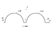
- FIG. 6 is a cross-sectional view of a toy container taken along the line FF of FIG. 6A. It is a side view of the toy container seen from the direction of the arrow G of FIG. 6A. It is a perspective view of the toy container in the toy accommodating state in the 2nd Embodiment.
- FIG. 8 is a cross-sectional view of a toy container taken along the line HH of FIG. 8A. It is a side view of the toy container seen from the direction of the arrow J of FIG. 8A. It is a side view of the toy container seen from the direction of the arrow K of FIG. 8A.
- FIG. 1 is a perspective view of the toy container 1 according to the first embodiment
- FIGS. 2A and 2B are a plan view and a side view of the toy container 1.
- 3A is a cross-sectional view of the toy container 1 taken along the line CC of FIG. 2A
- FIG. 3B is a side view of the toy container 1 as viewed from the direction of arrow D in FIG. 2A.
- FIGS. 1 to 3 show a toy container 1 in a molded state (as it is after molding).
- the toy container 1 As shown in FIGS. 1 to 3, the toy container 1 according to the first embodiment is formed in a capsule shape, and a product (toy; not shown) can be taken out and stored inside the capsule.
- a plurality of the toy containers 1 are stored inside, for example, a product discharging device (not shown) in a state where the products are stored.
- the product ejection device When a coin is inserted from the coin insertion slot and the handle is rotated, the product ejection device ejects one of the plurality of toy containers 1 housed inside to the outlet.
- the toy container 1 is made of paper, and the whole is integrally molded with paper by the manufacturing process described later.
- the material paper may contain a predetermined amount (for example, 50 wt% or more) of pulp (vegetable fiber).
- the content of the adhesive is a certain amount or less, mainly from the viewpoint of recyclability.
- the toy container 1 includes a pair of accommodating portions 2 (first accommodating portion 2A and second accommodating portion 2B) and a connecting portion 3 for connecting the pair of accommodating portions 2.
- Each of the pair of accommodating portions 2 is formed in a substantially hemispherical shape of the same size, and has a substantially hemispherical accommodating space inside.
- the connecting portion 3 connects the opening edges of the pair of accommodating portions 2 in a living hinge shape. More specifically, in the molded toy container 1, the pair of accommodating portions 2 extend in a brim shape from the opening edges of the pair of accommodating portions 2 in a state where the openings of the pair of accommodating portions 2 are arranged side by side in the same direction.
- the connecting portion 3 connects the pair of accommodating portions 2.
- each of the pair of accommodating portions 2 has a reinforcing portion 21 projecting to the outside thereof.
- the reinforcing portion 21 of the present embodiment is formed in a pillar surface shape having a radius similar to that of the accommodating portion 2 and having a predetermined width, and is formed from one end of the opening edge portion connected to the connecting portion 3 through the apex to the other of the opening edge portion. It extends to the edge. Both ends of the reinforcing portion 21 in the width direction project outward in a stepped manner with respect to the other spherical portions of the accommodating portion 2. Therefore, the strength of the accommodating portion 2 against deformation is improved.
- the reinforcing portion 21 has a pillar surface shape, a label can be attached or directly printed on the outer surface of the reinforcing portion 21, and the surface can be used as an information display surface showing information on, for example, the housed toy. ..
- a paper label paper tape or the like.
- the specific shape of the reinforcing portion 21 is not particularly limited as long as it is formed in a concave or convex shape with respect to the other portion of the accommodating portion 2. For example, a plurality of may extend radially from the top of the accommodating portion 2.
- the surface includes a developable surface (a surface that can be developed into a flat surface without expanding and contracting), and the pillar surface or the flat surface is formed. It is more preferable to include it.
- the reinforcing portion 21 may be provided in at least one of the pair of accommodating portions 2. Examples of other reinforcing portions 21 include those having one end in contact with the edge of the accommodating portion 2, those provided with a plurality of small ones having a surface such as a rectangular shape, those having a honeycomb structure, and those having irregularities. Examples thereof include those formed by changing the thickness of paper.
- each of the pair of accommodating portions 2 has a plurality of through holes 22.
- two through holes 22 are formed in the spherical portions on both sides of each accommodating portion 2 with the reinforcing portion 21 interposed therebetween.
- the size, position, and quantity of the plurality of through holes 22 are not particularly limited. These plurality of through holes 22 secure an airway even when the toy container 1 is aspirated.
- the first accommodating portion 2A has a locking projection 23.
- the locking projection 23 is provided at a position on the opening edge portion of the first accommodating portion 2A, which is opposite to the position where the connecting portion 3 is connected.
- the locking projection 23 extends radially outward from the opening edge of the first accommodating portion 2A, which has a substantially circular shape in a plan view.
- the tip of the locking projection 23 is formed to have a width wider than the width of the locking hole 24 described later. Specifically, the locking projection 23 extends toward the tip with a predetermined width and has a predetermined width. On the tip side thereof, hook portions 23a are provided on both sides in the width direction, which gradually widen toward the tip after being stepped wide.
- the second accommodating portion 2B has a locking hole 24 in which the locking projection 23 of the first accommodating portion 2A is locked.
- the locking hole 24 is provided at a position opposite to the position where the connecting portion 3 is connected in the opening edge portion of the second accommodating portion 2B, and is provided on the reinforcing portion 21 in the present embodiment. There is.
- the locking hole 24 is formed to have a width wider than the width of the tip end side and the base end side of the locking projection 23 and narrower than the maximum width of the hook portion 23a.
- each of the pair of accommodating portions 2 has a flange portion 25 projecting outward from the substantially circular opening edge portion over substantially the entire circumference of the opening edge portion.
- the flange portion 25 of the second accommodating portion 2B is provided with a vertical wall 25a erected from the outer peripheral edge thereof in the opening direction of the opening edge portion.
- the vertical wall 25a is provided over substantially the entire range on both sides of the flange portion 25 with the reinforcing portion 21 sandwiched in a plan view.
- Toy storage state> 4A is a perspective view of the toy container 1 in the toy housing state
- FIG. 4B is a cross-sectional view of the toy container 1 along the line EE of FIG. 4A
- FIG. 4C is a cross-sectional view of the opening edge portion in the toy housing state. It is a partial sectional view.
- the toy container 1 is brought into the toy accommodating state by closing the openings of the pair of accommodating portions 2 with each other from the molded state. Specifically, as shown in FIGS. 4A and 4B, from the molded state, the connecting portions 3 are bent and the opening edges (flange portions 25) of the pair of accommodating portions 2 are aligned with each other. The openings of the pair of accommodating portions 2 are closed. In this way, the toy container 1 is in a substantially spherical toy storage state. At this time, the goods (toys) are stored in the storage space inside the pair of storage units 2.
- the locking projection 23 of the first accommodating portion 2A is bent toward the second accommodating portion 2B so as to sandwich the flange portion 25 of the second accommodating portion 2B, and is inserted into the locking hole 24 of the second accommodating portion 2B. ..
- the locking projection 23 is inserted until the hook portion 23a is inserted into the locking hole 24 and enters the accommodation space.
- the hook portion 23a of the locking projection 23 is locked in the locking hole 24, and the toy accommodating state in which the pair of accommodating portions 2 close the opening is maintained.
- the locking projection 23 connects the pair of accommodating portions 2 in a living hinge shape when inserted into the locking hole 24. Further, in this toy accommodating state, as shown in FIG.
- a gap S between the opening edges (flange portion 25) of the pair of accommodating portions 2 is provided in the collar portion 25 of the second accommodating portion 2B. It is covered by a standing wall 25a. As a result, it is possible to prevent the inside (product) from being visually recognized from the gap S and dust from being mixed in.
- the locking projection 23 may be manually torn (cut into pieces) to open the toy container 1. .. Since the locking projection 23 (connecting portion 3) is made of paper, it can be easily torn.
- the locking projection 23 (or the connecting portion 3) may be provided with a notch on its side so that it can be easily torn.
- the toy container 1 is made of paper containing a predetermined amount of pulp, the toy container 1 is made into a global environment as compared with the conventional case where the toy container 1 is made of plastic that does not decompose naturally. It can be gentle. In addition, printing and coloring can be easily performed as compared with the conventional one made of plastic.
- At least one of the pair of substantially hemispherical accommodating portions 2 has the reinforcing portion 21 formed in a concave or convex shape with respect to the other portion of the accommodating portion 2.
- the reinforcing portion 21 can improve the strength of the accommodating portion 2 against deformation.
- the outer surface of the accommodating portion 2 of the reinforcing portion 21 includes a flat surface or a pillar surface. Therefore, a label can be attached or directly printed on the surface of the reinforcing portion 21, and the surface can be used as an information display surface.
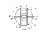
- FIG. 5 is a perspective view of the toy container 4 according to the second embodiment
- FIGS. 6A and 6B are a plan view and a side view of the toy container 4.
- 7A is a cross-sectional view of the toy container 4 taken along the line FF of FIG. 6A
- FIG. 7B is a side view of the toy container 4 as viewed from the direction of arrow G of FIG. 6A.
- FIGS. 5 to 7 show a toy container 4 in a molded state (as it is after molding).
- the toy container 4 according to the second embodiment is formed in a capsule shape like the toy container 1 according to the first embodiment, and a product (toy; (Not shown) can be taken out and stored.
- a plurality of the toy containers 4 are stored inside, for example, a product discharging device (not shown) in a state where the products are stored.
- the product discharge device discharges one of the plurality of toy containers 4 housed inside to the outlet.
- the toy container 4 is made of paper, and the whole is integrally molded with paper by the manufacturing process described later.
- the material paper may contain a predetermined amount (for example, 50 wt% or more) of pulp (vegetable fiber).
- the content of the adhesive is a certain amount or less, mainly from the viewpoint of recyclability.
- the toy container 4 includes a pair of accommodating portions 5 (first accommodating portion 5A and second accommodating portion 5B) and a connecting portion 3 for connecting the pair of accommodating portions 5.
- Each of the pair of accommodating portions 5 is formed in a substantially hemispherical shape having the same size as the accommodating portion 2 of the first embodiment, and has a substantially hemispherical accommodating space inside.
- the connecting portion 3 connects the opening edges of the pair of accommodating portions 5 in a living hinge shape. More specifically, in the molded toy container 4, the pair of accommodating portions 5 extend in a brim shape from the opening edges of the pair of accommodating portions 5 in a state where the openings are arranged in the same direction.
- the connecting portion 3 connects the pair of accommodating portions 5.
- each of the pair of accommodating portions 5 has a reinforcing portion 21 projecting to the outside thereof.
- the reinforcing portion 21 of the present embodiment is configured in the same manner as that of the first embodiment. That is, the reinforcing portion 21 is formed in a pillar surface shape having a predetermined width having a radius similar to that of the accommodating portion 5, and extends from one end of the opening edge portion connected to the connecting portion 3 to the other end of the opening edge portion via the top portion. It extends all the way. Both ends of the reinforcing portion 21 in the width direction project outward in a stepped manner with respect to the other spherical portions of the accommodating portion 5. Therefore, the strength of the accommodating portion 5 against deformation is improved.
- the reinforcing portion 21 has a pillar surface shape, a label can be attached or directly printed on the outer surface of the reinforcing portion 21, and the surface can be used as an information display surface showing information on, for example, the housed toy. ..
- a paper label paper tape or the like.
- the specific shape of the reinforcing portion 21 is not particularly limited as long as it is formed in a concave or convex shape with respect to the other portion of the accommodating portion 5. For example, a plurality of may extend radially from the top of the accommodating portion 5.
- the surface includes a developable surface (a surface that can be developed into a flat surface without expanding and contracting), and the pillar surface or the flat surface is formed. It is more preferable to include it.
- the reinforcing portion 21 may be provided in at least one of the pair of accommodating portions 5. Examples of other reinforcing portions 21 include those having one end in contact with the edge of the accommodating portion 5, those provided with a plurality of small ones having a surface such as a rectangular shape, those having a honeycomb structure, and those having irregularities. Examples thereof include those formed by changing the thickness of paper.
- each of the pair of accommodating portions 5 has a plurality of through holes 22.
- two through holes 22 are formed in spherical portions on both sides of each accommodating portion 5 with the reinforcing portion 21 sandwiched between them.
- the size, position, and quantity of the plurality of through holes 22 are not particularly limited. These plurality of through holes 22 secure an airway even when the toy container 4 is aspirated.
- each of the pair of accommodating portions 5 has a flange portion 25 projecting outward from the substantially circular opening edge portion over substantially the entire circumference of the opening edge portion. The flange portion 25 may be provided with the vertical wall 25a of the first embodiment.
- the first accommodating portion 5A has a locking projection 23.
- the locking projection 23 is configured in the same manner as that of the first embodiment. That is, the locking projection 23 is provided at a position (opposite position of the connecting portion 3) of the opening edge portion of the first accommodating portion 5A, which is opposite to the position where the connecting portion 3 is connected.
- the locking projection 23 extends radially outward from the opening edge of the first accommodating portion 5A, which has a substantially circular shape in a plan view.
- the tip of the locking projection 23 is formed to have a width wider than the width of the locking hole 24 described later. Specifically, the locking projection 23 extends toward the tip with a predetermined width and has a predetermined width. On the tip side thereof, hook portions 23a are provided on both sides in the width direction, which gradually widen toward the tip after being stepped wide.
- the first accommodating portion 5A has a locking recess 26 capable of locking the locking portion 27 of the second accommodating portion 5B, which will be described later.
- the locking recess 26 is an example of the first locking portion according to the present invention.
- the locking recess 26 includes the opening edge portion of the first accommodating portion 5A, including the position of the connecting portion 3 and the facing position of the connecting portion 3 (the position of the locking projection 23). They are arranged at two locations on the sides facing each other so as to be divided into four equal parts.
- Each locking recess 26 is formed in a shape in which the flange portion 25 of the opening edge portion is cut out with a predetermined width.
- each locking recess 26 is not uniform, and is formed so as to narrow toward the outer side in the radial direction of the opening edge portion (the tip end side of the flange portion 25).
- the position and quantity of the locking recesses 26 are not particularly limited, but a plurality of locking recesses 26 may be provided at positions other than the position of the connecting portion 3 and the facing position of the connecting portion 3 in the opening edge portion of the first accommodating portion 5A. preferable.
- the second accommodating portion 5B has a locking hole 24 capable of locking the locking projection 23 of the first accommodating portion 5A.
- the locking hole 24 is configured in the same manner as that of the first embodiment. That is, the locking hole 24 is provided at a position (opposite position of the connecting portion 3) opposite to the position where the connecting portion 3 is connected in the opening edge portion of the second accommodating portion 5B. In the form, it is provided on the reinforcing portion 21.
- the locking hole 24 is formed to have a width wider than the width of the tip end side and the base end side of the locking projection 23 and narrower than the maximum width of the hook portion 23a.
- the second accommodating portion 5B has a lock portion 27.
- the lock portion 27 is an example of the first protrusion portion according to the present invention.
- the lock portion 27 is provided at a position corresponding to the locking recess 26 of the first accommodating portion 5A.
- the lock portion 27 is opened in a plan view including the position of the connecting portion 3 and the facing position of the connecting portion 3 (the position of the locking hole 24) in the opening edge portion of the second accommodating portion 5B.
- the edges are arranged at two locations on the sides facing each other so as to divide the edges into four equal parts.
- Each lock portion 27 extends radially outward from the flange portion 25 in the radial direction, and the collar portions 25 on both sides thereof are cut out.
- Each lock portion 27 is formed so that the width of the base end portion is narrower than that of the tip end side thereof.
- the width of the base end portion is formed to be the same as or slightly narrower than the maximum width of the locking recess 26 of the first accommodating portion 5A, and the width on the tip end side of the proximal end portion is the locking of the first accommodating portion 5A. It is formed slightly wider than the maximum width of the recess 26.
- the position and quantity of the lock portions 27 are not particularly limited, but it is preferable that a plurality of lock portions 27 are provided at positions other than the positions of the connecting portions 3 and the opposing positions of the connecting portions 3 in the opening edge portion of the second accommodating portion 5B. .. However, it goes without saying that it is arranged at a position corresponding to the locking recess 26 of the first accommodating portion 5A.
- the opening edge of the second accommodating portion 5B (first accommodating portion 5A) is divided into three equal parts in a plan view without providing the locking hole 24 (locking protrusion 23) at the opposite position of the connecting portion 3.
- Locking portions 27 (locking recesses 26) may be arranged at three locations on the opening edge portion.
- each of the pair of accommodating portions 5 has a finger hook portion 28 capable of locking a finger.
- the finger hook portion 28 is arranged around the facing position of the connecting portion 3 (that is, the position of the locking projection 23 or the locking hole 24) in the opening edge portion of each accommodating portion 5, and is reinforced in the present embodiment. It is provided on the portion 21.
- Each finger hook 28 has a size that allows a finger to be inserted, and is formed in a horizontally long hole shape (hole shape) that is slightly narrower than the reinforcing portion 21.
- the hole shape of each finger hook 28 is gently curved so that the opening edge side becomes a larger hole toward the center, and the opposite side is formed in a straight line, which is a substantially arcuate shape.
- the finger hooks 28 do not have to be provided in both of the pair of accommodating portions 5, and may be provided in at least one of the pair of accommodating portions 5.
- the position of the finger hook portion 28 is not particularly limited as long as it is around the opening edge portion, but it is preferably around the opposite position of the connecting portion 3.
- the shape of the finger hook portion 28 is not limited to a hole shape as long as the finger can be locked, and may be, for example, an uneven shape (including one having a plurality of small uneven portions). Further, the front view shape and the like are not limited to those of the present embodiment.
- FIG. 8A is a perspective view of the toy container 4 in the toy housing state
- FIG. 8B is a cross-sectional view of the toy container 4 taken along the line HH of FIG. 8A.
- 9 and 10 are side views of the toy container 4 as viewed from the directions of arrows J and K in FIG. 8A.
- the toy container 4 is brought into the toy accommodating state by closing the openings of the pair of accommodating portions 5 with each other from the molded state. Specifically, as shown in FIGS. 8 to 10, from the molded state, the connecting portions 3 are bent and the opening edges (flange portions 25) of the pair of accommodating portions 5 are aligned with each other. The openings of the pair of accommodating portions 5 are closed. In this way, the toy container 4 is in a substantially spherical toy storage state. At this time, the goods (toys) are stored in the storage space inside the pair of storage portions 5.
- the locking projection 23 of the first accommodating portion 5A is bent toward the second accommodating portion 5B so as to sandwich the flange portion 25 of the second accommodating portion 5B, and is inserted into the locking hole 24 of the second accommodating portion 5B. ..
- the locking projection 23 is inserted until the hook portion 23a is inserted into the locking hole 24 and enters the accommodation space.
- the hook portion 23a of the locking projection 23 is locked in the locking hole 24, and the toy accommodating state in which the pair of accommodating portions 5 close the opening is maintained.
- the locking projection 23 connects the pair of accommodating portions 5 in a living hinge shape when inserted into the locking hole 24.
- each lock portion 27 of the second accommodating portion 5B is bent toward the first accommodating portion 5A at the base end portion and inserted into the two locking recesses 26 of the first accommodating portion 5A from the outside in the radial direction.
- Each lock portion 27 is locked in the locking recess 26. That is, each lock portion 27 is radially locked to the tip end side portion of the inserted locking recess 26, and is prevented from falling off from the locking recess 26 in the radial direction and returning to the extended state. Further, each lock portion 27 is also locked in the direction in which the pair of accommodating portions 5 are opened (vertical direction in FIG. 10) by the inserted locking recess 26, and falls off from the locking recess 26 in that direction. Is prevented. As a result, the toy accommodating state in which the pair of accommodating portions 5 close the openings is more firmly held.
- the fingers of both hands for example, two fingers each of the index finger and the middle finger
- the pair of accommodating portions 5 may be pulled apart by both hands so as to open from the opposite positions of the connecting portions 3, and the toy container 4 may be opened. Since the locking projection 23 (or connecting portion 3) and the locking portion 27 that hold the toy accommodating state are made of paper, it is relatively possible to open the pair of accommodating portions 5 by putting a finger on the finger hook portion 28 and exerting force. It can be easily broken.
- the locking projection 23 (or the connecting portion 3) and the locking portion 27 may be individually torn (cut into pieces) to open the toy container 4.
- the locking projection 23 (or the connecting portion 3) or the locking portion 27 may be provided with a notch on the side portion thereof so as to be easily torn.
- the toy container 4 is manufactured by the same manufacturing method (manufacturing process) as the toy container 1 of the first embodiment.
- the second accommodating portion 5B has a bendable lock portion 27 at the opening edge portion, and the first accommodating portion 5A opens a locking recess 26 capable of locking the lock portion 27. Have on the edge.
- the lock portion 27 is bent and locked in the locking recess 26 in a state where the opening edges of the pair of accommodating portions 5 are aligned, thereby suppressing the formation of a gap in the mating surface of the opening edges.
- a pair of accommodating portions 5 can be fixed. Therefore, the pair of paper accommodating portions 5 can be suitably fixed.
- each of the locking portion 27 and the locking recess 26 sets the position of the connecting portion 3 and the facing position of the connecting portion 3 among the opening edges of each of the pair of accommodating portions 5.
- a plurality of (two in this embodiment) are arranged at the positions other than the above. As a result, it is possible to more reliably suppress the formation of a gap on the mating surface of the opening edge portion, and to more preferably fix the pair of accommodating portions 5.
- At least one of the pair of accommodating portions 5 has a finger hook portion 28 on which a finger can be locked around the opening edge portion.
- the finger hook portion 28 is arranged around the opposite position of the connecting portion 3 in the opening edge portion of the accommodating portion 5, the pair of accommodating portions 5 are arranged with the connecting portion 3 as a fulcrum. It is easy to apply force in the opening direction, and the toy container 4 can be opened more easily.
- the embodiment to which the present invention can be applied is not limited to the above-described embodiment, and can be appropriately changed without departing from the spirit of the present invention.
- each of the pair of accommodating portions 2 and 5 is substantially hemispherical, but if the pair of accommodating portions 2 and 5 are combined with each other to define an accommodating space.
- the shape is not particularly limited.
- each of the accommodating portions 2 and 5 may be formed in a concave shape that is not hemispherical, one accommodating portion 2 and 5 has a large accommodating space, and the other accommodating portions 2 and 5 close the opening. It may be in the shape of a lid.
- the pair of accommodating portions 2 and 5 may be separate bodies that are not connected by a hinge.
- the locking projection 23 is locked in the locking hole 24 to maintain the toy housing state in which the openings of the pair of housing portions 2 and 5 are closed.
- the method of closing the openings of the pair of accommodating portions 2 and 5 is not limited to this, and for example, the opening edges (flange portions 25) of the pair of accommodating portions 2 and 5 may be glued to each other. It may be joined with paper tape.
- the accommodating portions 2 in the first embodiment is provided with a finger hook portion 28 provided in the accommodating portion 5 of the second embodiment.
- the locking projection 23 may be configured to be inserted into the locking hole 24 from the inside of the accommodating portions 2 and 5 instead of from the outside of the accommodating portions 2 and 5.
- the locking projection 23 may have a notch formed at the tip thereof, for example, so that the locking projection 23 can be easily inserted into the locking hole 24.
- the flange portion 25 may not be provided at the opening edge portion of each of the accommodating portions 2 and 5. In this case, in the toy accommodating state, the opening edges of the pair of accommodating portions 2 and 5 are in contact with each other.
- the locking projection 23 and the locking hole 24 may have the same locking structure as the locking portion 27 and the locking recess 26 of the second embodiment.
- the locking recess 26 is provided in the first accommodating portion 5A, and the locking portion 27 is provided in the second accommodating portion 5B.
- the locking portion 27 is provided in the first accommodating portion 5A.
- a locking recess 26 may be provided in the second accommodating portion 5B.
- the locking portion 27 and the locking recess 26 may be provided in the pair of accommodating portions 2 of the first embodiment.
- the toy containers 1 and 4 are composed of a pair (2 bodies) of accommodating portions 2 and 5, but it is also possible that the toy containers 1 and 4 are composed of accommodating portions forming a set of 3 or more bodies. Good.
- the present invention is useful for realizing a container for toys that is friendly to the global environment.
Landscapes
- Engineering & Computer Science (AREA)
- Mechanical Engineering (AREA)
- Ceramic Engineering (AREA)
- Toys (AREA)
- Packaging Of Annular Or Rod-Shaped Articles, Wearing Apparel, Cassettes, Or The Like (AREA)
- Cartons (AREA)
Abstract
A toy container 1 is for accommodating a toy and is made of paper containing a predetermined amount of pulp. Accordingly, the toy container 1 can be an earth environment-friendly product as compared to conventional plastic products that are not naturally decomposable.
Description
本発明は、玩具を収容する玩具用容器に関する。
The present invention relates to a toy container for accommodating toys.
従来、カプセルトイなどに用いられるカプセル状の玩具用容器が知られている(例えば、特許文献1参照)。
この種の玩具用容器は、一部が紙製のものもあるが(例えば、特許文献2参照)、PP(ポリプロピレン)などのプラスチック(合成樹脂)製のものが一般的であった。 Conventionally, capsule-shaped toy containers used for capsule toys and the like are known (see, for example, Patent Document 1).
Some toy containers of this type are made of paper (see, for example, Patent Document 2), but are generally made of plastic (synthetic resin) such as PP (polypropylene).
しかしながら、自然分解しないプラスチックは環境負荷が高い。特許文献2に記載のカプセルでは、紙製の部分が一部のみに限定されており、他の部分はやはりプラスチック製である。
そこで、本発明は、地球環境に優しい玩具用容器を提供することを目的とする。 However, plastics that do not decompose naturally have a high environmental load. In the capsule described in Patent Document 2, the paper part is limited to only a part, and the other part is also made of plastic.
Therefore, an object of the present invention is to provide a container for toys that is friendly to the global environment.
第1の手段は、玩具を収容する玩具用容器であって、
所定量のパルプを含む紙製であることを特徴とする。 The first means is a toy container for accommodating toys.
It is characterized by being made of paper containing a predetermined amount of pulp.
所定量のパルプを含む紙製であることを特徴とする。 The first means is a toy container for accommodating toys.
It is characterized by being made of paper containing a predetermined amount of pulp.
第2の手段は、第1の手段において、
略半球状の一対の収容部を有し、
前記一対の収容部の少なくとも一方は、当該収容部の他の部分に対して凹状又は凸状に形成された補強部を有することを特徴とする。 The second means is, in the first means,
It has a pair of substantially hemispherical housings and
At least one of the pair of accommodating portions is characterized by having a reinforcing portion formed in a concave or convex shape with respect to the other portion of the accommodating portion.
第3の手段は、第2の手段において、
前記補強部は、当該収容部の外側の表面が平面又は柱面を含むことを特徴とする。 The third means is, in the second means,
The reinforcing portion is characterized in that the outer surface of the accommodating portion includes a flat surface or a column surface.
前記補強部は、当該収容部の外側の表面が平面又は柱面を含むことを特徴とする。 The third means is, in the second means,
The reinforcing portion is characterized in that the outer surface of the accommodating portion includes a flat surface or a column surface.
第4の手段は、第2又は第3の手段において、
前記一対の収容部の開口縁部をリビングヒンジ状に連結する連結部を有することを特徴とする。 The fourth means is, in the second or third means,
It is characterized by having a connecting portion for connecting the opening edges of the pair of accommodating portions in a living hinge shape.
前記一対の収容部の開口縁部をリビングヒンジ状に連結する連結部を有することを特徴とする。 The fourth means is, in the second or third means,
It is characterized by having a connecting portion for connecting the opening edges of the pair of accommodating portions in a living hinge shape.
第5の手段は、第4の手段において、
前記一対の収容部の一方は、開口縁部のうち前記連結部が連結された位置とは反対側の位置に、係止突起を有し、
前記一対の収容部の他方は、開口縁部のうち前記連結部が連結された位置とは反対側の位置に、前記係止突起が係止される係止孔を有することを特徴とする。 The fifth means is, in the fourth means,
One of the pair of accommodating portions has a locking projection at a position of the opening edge portion opposite to the position where the connecting portion is connected.
The other of the pair of accommodating portions is characterized by having a locking hole in which the locking projection is locked at a position of the opening edge portion opposite to the position where the connecting portion is connected.
第6の手段は、第5の手段において、
前記係止突起は、先端部が前記係止孔の幅よりも広い幅に形成されていることを特徴とする。 The sixth means is, in the fifth means,
The locking projection is characterized in that the tip portion is formed to have a width wider than the width of the locking hole.
前記係止突起は、先端部が前記係止孔の幅よりも広い幅に形成されていることを特徴とする。 The sixth means is, in the fifth means,
The locking projection is characterized in that the tip portion is formed to have a width wider than the width of the locking hole.
第7の手段は、第5又は第6の手段において、
前記係止突起は、前記一対の収容部の互いの開口縁部を合わせた状態で、屈曲させて前記係止孔に挿入されるように構成されていることを特徴とする。 The seventh means, in the fifth or sixth means,
The locking projection is configured to be bent and inserted into the locking hole in a state where the opening edges of the pair of accommodating portions are aligned with each other.
第8の手段は、第7の手段において、
前記係止突起は、前記係止孔に挿入された状態で、前記一対の収容部をリビングヒンジ状に連結することを特徴とする。 The eighth means, in the seventh means,
The locking projection is characterized in that the pair of accommodating portions are connected in a living hinge shape while being inserted into the locking hole.
前記係止突起は、前記係止孔に挿入された状態で、前記一対の収容部をリビングヒンジ状に連結することを特徴とする。 The eighth means, in the seventh means,
The locking projection is characterized in that the pair of accommodating portions are connected in a living hinge shape while being inserted into the locking hole.
第9の手段は、第1~第8のいずれか一の手段において、
略半球状の一対の収容部を有し、
前記一対の収容部の一方は、屈曲可能な第1突起部を開口縁部に有し、
前記一対の収容部の他方は、前記第1突起部を係止可能な第1係止部を開口縁部に有することを特徴とする。 The ninth means is, in any one of the first to eighth means,
It has a pair of substantially hemispherical housings and
One of the pair of accommodating portions has a bendable first protrusion on the opening edge.
The other of the pair of accommodating portions is characterized in that the opening edge portion has a first locking portion capable of locking the first protrusion portion.
第10の手段は、第9の手段において、
前記一対の収容部の開口縁部をリビングヒンジ状に連結する連結部を有し、
前記第1突起部及び前記第1係止部の各々は、前記一対の収容部それぞれの開口縁部のうち、前記連結部の位置と前記連結部の対向位置とを除く位置に、複数配置されていることを特徴とする。 The tenth means, in the ninth means,
It has a connecting portion that connects the opening edges of the pair of accommodating portions in a living hinge shape.
A plurality of the first protrusions and the first locking portions are arranged at positions other than the positions of the connecting portions and the opposing positions of the connecting portions in the opening edges of the pair of accommodating portions. It is characterized by being.
第11の手段は、第9又は第10の手段において、
前記一対の収容部の少なくとも一方は、指を係止可能な指掛け部を開口縁部周辺に有することを特徴とする。 The eleventh means, in the ninth or tenth means,
At least one of the pair of accommodating portions is characterized by having a finger hook portion on which a finger can be locked around the opening edge portion.
前記一対の収容部の少なくとも一方は、指を係止可能な指掛け部を開口縁部周辺に有することを特徴とする。 The eleventh means, in the ninth or tenth means,
At least one of the pair of accommodating portions is characterized by having a finger hook portion on which a finger can be locked around the opening edge portion.
第12の手段は、第11の手段において、
前記一対の収容部の開口縁部をリビングヒンジ状に連結する連結部を有し、
前記指掛け部は、前記一対の収容部の少なくとも一方の開口縁部のうち、前記連結部の対向位置の周辺に配置されていることを特徴とする。 The twelfth means in the eleventh means
It has a connecting portion that connects the opening edges of the pair of accommodating portions in a living hinge shape.
The finger hook portion is characterized in that it is arranged around at least one opening edge portion of the pair of accommodating portions at a position facing the connecting portion.
第1の手段によれば、玩具用容器が所定量のパルプを含む紙製であるので、自然分解しないプラスチック製であった従来に比べ、玩具用容器を地球環境に優しいものとすることができる。
According to the first means, since the toy container is made of paper containing a predetermined amount of pulp, the toy container can be made more environmentally friendly than the conventional one made of plastic that does not decompose naturally. ..
第2の手段によれば、略半球状の一対の収容部の少なくとも一方が、当該収容部の他の部分に対して凹状又は凸状に形成された補強部を有するので、この補強部により、変形に対する収容部の強度を向上できる。
According to the second means, at least one of the pair of substantially hemispherical accommodating portions has a reinforcing portion formed in a concave or convex shape with respect to the other portion of the accommodating portion. The strength of the accommodating portion against deformation can be improved.
第3の手段によれば、補強部は収容部の外側の表面が平面又は柱面を含んでいる。そのため、この補強部の表面にラベルを貼ったり直接印字したりして、当該表面を情報表示面として利用できる。
According to the third means, the outer surface of the accommodating portion of the reinforcing portion includes a flat surface or a column surface. Therefore, a label can be attached or directly printed on the surface of the reinforcing portion, and the surface can be used as an information display surface.
第9の手段によれば、一対の収容部の開口縁部を合わせた状態で第1突起部を屈曲させて第1係止部に係止させることで、開口縁部の合わせ面に隙間ができるのを抑制して一対の収容部を固定できる。したがって、紙製の一対の収容部を好適に固定することができる。
According to the ninth means, by bending the first projection portion in a state where the opening edges of the pair of accommodating portions are aligned and locking the first projection portion with the first locking portion, a gap is created in the mating surface of the opening edge portions. A pair of accommodating portions can be fixed by suppressing the formation. Therefore, a pair of paper accommodating portions can be suitably fixed.
第10の手段によれば、第1突起部及び第1係止部の各々が、一対の収容部それぞれの開口縁部のうち、一対の収容部を連結する連結部の位置と当該連結部の対向位置とを除く位置に複数配置されている。これにより、開口縁部の合わせ面に隙間ができるのをより確実に抑制し、一対の収容部をより好適に固定できる。
According to the tenth means, each of the first protrusion and the first locking portion is the position of the connecting portion connecting the pair of accommodating portions and the position of the connecting portion among the opening edges of each of the pair of accommodating portions. A plurality of positions are arranged except for the opposite positions. As a result, it is possible to more reliably suppress the formation of a gap in the mating surface of the opening edge portion, and to more preferably fix the pair of accommodating portions.
第11の手段によれば、一対の収容部の少なくとも一方が指を係止可能な指掛け部を開口縁部周辺に有するので、玩具収容状態の玩具用容器において当該指掛け部に指を掛けて一対の収容部を引き離すことで、玩具用容器を容易に開放できる。
According to the eleventh means, since at least one of the pair of accommodating portions has a finger hook portion around the opening edge portion to which the finger can be locked, the finger hook portion is hung on the finger hook portion in the toy container in the toy accommodating state. The toy container can be easily opened by pulling the housing part apart.
第12の手段によれば、指掛け部が収容部の開口縁部のうち連結部の対向位置の周辺に配置されているので、連結部を支点として一対の収容部が開く方向に力を加えやすく、玩具用容器をより容易に開放できる。
According to the twelfth means, since the finger hook portion is arranged around the opposite position of the connecting portion in the opening edge portion of the accommodating portion, it is easy to apply a force in the opening direction of the pair of accommodating portions with the connecting portion as a fulcrum. , The toy container can be opened more easily.
[1.第1実施形態]
以下、本発明に係る玩具用容器の第1実施形態について説明する。 [1. First Embodiment]
Hereinafter, the first embodiment of the toy container according to the present invention will be described.
以下、本発明に係る玩具用容器の第1実施形態について説明する。 [1. First Embodiment]
Hereinafter, the first embodiment of the toy container according to the present invention will be described.
<1-1.玩具用容器の構成>
図1は、第1実施形態に係る玩具用容器1の斜視図であり、図2A、図2Bは、玩具用容器1の平面図及び側面図である。図3Aは、図2AのC-C線での玩具用容器1の断面図であり、図3Bは、図2Aの矢印Dの方向から見た玩具用容器1の側面図である。なお、図1~図3では、成形状態(成形後のままの状態)の玩具用容器1を示している。 <1-1. Composition of toy container >
FIG. 1 is a perspective view of thetoy container 1 according to the first embodiment, and FIGS. 2A and 2B are a plan view and a side view of the toy container 1. 3A is a cross-sectional view of the toy container 1 taken along the line CC of FIG. 2A, and FIG. 3B is a side view of the toy container 1 as viewed from the direction of arrow D in FIG. 2A. Note that FIGS. 1 to 3 show a toy container 1 in a molded state (as it is after molding).
図1は、第1実施形態に係る玩具用容器1の斜視図であり、図2A、図2Bは、玩具用容器1の平面図及び側面図である。図3Aは、図2AのC-C線での玩具用容器1の断面図であり、図3Bは、図2Aの矢印Dの方向から見た玩具用容器1の側面図である。なお、図1~図3では、成形状態(成形後のままの状態)の玩具用容器1を示している。 <1-1. Composition of toy container >
FIG. 1 is a perspective view of the
図1~図3に示すように、第1実施形態に係る玩具用容器1は、カプセル状に形成され、その内部に商品(玩具;図示省略)を取出し可能に収容する。この玩具用容器1は、商品が収容された状態で、例えば商品排出装置(図示せず)の内部に複数収納される。商品排出装置は、コイン投入口から硬貨が投入されてハンドルが回動操作されると、内部に収納された複数の玩具用容器1のうちの一つを取出口に排出する。
As shown in FIGS. 1 to 3, the toy container 1 according to the first embodiment is formed in a capsule shape, and a product (toy; not shown) can be taken out and stored inside the capsule. A plurality of the toy containers 1 are stored inside, for example, a product discharging device (not shown) in a state where the products are stored. When a coin is inserted from the coin insertion slot and the handle is rotated, the product ejection device ejects one of the plurality of toy containers 1 housed inside to the outlet.
玩具用容器1は紙製であり、後述の製造工程により、全体が紙で一体成形されている。材料の紙は、所定量(例えば50wt%以上)のパルプ(植物繊維)を含有するものであればよい。ただし、主にリサイクル性の観点から、接着剤の含有量が一定量以下であることが好ましい。
The toy container 1 is made of paper, and the whole is integrally molded with paper by the manufacturing process described later. The material paper may contain a predetermined amount (for example, 50 wt% or more) of pulp (vegetable fiber). However, it is preferable that the content of the adhesive is a certain amount or less, mainly from the viewpoint of recyclability.
具体的に、玩具用容器1は、一対の収容部2(第1収容部2A及び第2収容部2B)と、当該一対の収容部2を連結する連結部3とを備えている。
一対の収容部2の各々は、同じ大きさの略半球状に形成され、内部に略半球状の収容空間を有している。
連結部3は、一対の収容部2の開口縁部をリビングヒンジ状に連結している。より詳しくは、成形状態の玩具用容器1では、一対の収容部2が互いの開口部を同じ方向に向けて並んだ状態で、一対の収容部2の開口縁部から鍔状に延出した連結部3が、当該一対の収容部2を連結している。 Specifically, thetoy container 1 includes a pair of accommodating portions 2 (first accommodating portion 2A and second accommodating portion 2B) and a connecting portion 3 for connecting the pair of accommodating portions 2.
Each of the pair of accommodating portions 2 is formed in a substantially hemispherical shape of the same size, and has a substantially hemispherical accommodating space inside.
The connectingportion 3 connects the opening edges of the pair of accommodating portions 2 in a living hinge shape. More specifically, in the molded toy container 1, the pair of accommodating portions 2 extend in a brim shape from the opening edges of the pair of accommodating portions 2 in a state where the openings of the pair of accommodating portions 2 are arranged side by side in the same direction. The connecting portion 3 connects the pair of accommodating portions 2.
一対の収容部2の各々は、同じ大きさの略半球状に形成され、内部に略半球状の収容空間を有している。
連結部3は、一対の収容部2の開口縁部をリビングヒンジ状に連結している。より詳しくは、成形状態の玩具用容器1では、一対の収容部2が互いの開口部を同じ方向に向けて並んだ状態で、一対の収容部2の開口縁部から鍔状に延出した連結部3が、当該一対の収容部2を連結している。 Specifically, the
Each of the pair of accommodating portions 2 is formed in a substantially hemispherical shape of the same size, and has a substantially hemispherical accommodating space inside.
The connecting
また、一対の収容部2の各々は、その外側へ突出する補強部21を有している。本実施形態の補強部21は、当該収容部2と同程度の半径を有する所定幅の柱面状に形成され、連結部3と繋がった開口縁部の一端から頂部を経て開口縁部の他端に至るように延在している。
補強部21の幅方向の両端は、収容部2の他の球状部分に対し、段付き状に外側へ突出している。そのため、変形に対する収容部2の強度が向上する。また、補強部21が柱面状であるため、その外側の表面にラベルを貼ったり直接印字したりして、当該表面を、例えば収容した玩具の情報等を示す情報表示面とすることができる。ラベルを貼る場合には、紙製のラベル(紙テープ等)を用いるのが好ましい。
なお、補強部21は、収容部2の他の部分に対して凹状又は凸状に形成されていれば、その具体形状は特に限定されない。例えば、収容部2の頂部から放射状に複数延在していたりしてもよい。ただし、補強部21の外側の表面を情報表示面とするには、当該表面が可展面(伸縮することなしに平面に展開することができる面)を含むことが好ましく、柱面又は平面を含むことがより好ましい。さらに、補強部21は、一対の収容部2のうちの少なくとも一方に設けられていればよい。
その他の補強部21の例としては、例えば、一端が収容部2の縁に接しているものや、矩形状などの表面を有する小型のものを複数設けたもの、ハニカム構造を有するもの、凹凸を紙の厚みの変化で形成したものなどが挙げられる。 Further, each of the pair of accommodating portions 2 has a reinforcingportion 21 projecting to the outside thereof. The reinforcing portion 21 of the present embodiment is formed in a pillar surface shape having a radius similar to that of the accommodating portion 2 and having a predetermined width, and is formed from one end of the opening edge portion connected to the connecting portion 3 through the apex to the other of the opening edge portion. It extends to the edge.
Both ends of the reinforcingportion 21 in the width direction project outward in a stepped manner with respect to the other spherical portions of the accommodating portion 2. Therefore, the strength of the accommodating portion 2 against deformation is improved. Further, since the reinforcing portion 21 has a pillar surface shape, a label can be attached or directly printed on the outer surface of the reinforcing portion 21, and the surface can be used as an information display surface showing information on, for example, the housed toy. .. When affixing a label, it is preferable to use a paper label (paper tape or the like).
The specific shape of the reinforcingportion 21 is not particularly limited as long as it is formed in a concave or convex shape with respect to the other portion of the accommodating portion 2. For example, a plurality of may extend radially from the top of the accommodating portion 2. However, in order to use the outer surface of the reinforcing portion 21 as an information display surface, it is preferable that the surface includes a developable surface (a surface that can be developed into a flat surface without expanding and contracting), and the pillar surface or the flat surface is formed. It is more preferable to include it. Further, the reinforcing portion 21 may be provided in at least one of the pair of accommodating portions 2.
Examples of other reinforcingportions 21 include those having one end in contact with the edge of the accommodating portion 2, those provided with a plurality of small ones having a surface such as a rectangular shape, those having a honeycomb structure, and those having irregularities. Examples thereof include those formed by changing the thickness of paper.
補強部21の幅方向の両端は、収容部2の他の球状部分に対し、段付き状に外側へ突出している。そのため、変形に対する収容部2の強度が向上する。また、補強部21が柱面状であるため、その外側の表面にラベルを貼ったり直接印字したりして、当該表面を、例えば収容した玩具の情報等を示す情報表示面とすることができる。ラベルを貼る場合には、紙製のラベル(紙テープ等)を用いるのが好ましい。
なお、補強部21は、収容部2の他の部分に対して凹状又は凸状に形成されていれば、その具体形状は特に限定されない。例えば、収容部2の頂部から放射状に複数延在していたりしてもよい。ただし、補強部21の外側の表面を情報表示面とするには、当該表面が可展面(伸縮することなしに平面に展開することができる面)を含むことが好ましく、柱面又は平面を含むことがより好ましい。さらに、補強部21は、一対の収容部2のうちの少なくとも一方に設けられていればよい。
その他の補強部21の例としては、例えば、一端が収容部2の縁に接しているものや、矩形状などの表面を有する小型のものを複数設けたもの、ハニカム構造を有するもの、凹凸を紙の厚みの変化で形成したものなどが挙げられる。 Further, each of the pair of accommodating portions 2 has a reinforcing
Both ends of the reinforcing
The specific shape of the reinforcing
Examples of other reinforcing
また、一対の収容部2の各々は、複数の貫通孔22を有している。本実施形態では、各収容部2のうち、補強部21を挟んだ両側の球状部分に、貫通孔22が2つずつ形成されている。ただし、複数の貫通孔22の大きさや位置、数量は、特に限定されない。
これら複数の貫通孔22により、玩具用容器1が誤嚥された場合にも気道が確保される。 Further, each of the pair of accommodating portions 2 has a plurality of throughholes 22. In the present embodiment, two through holes 22 are formed in the spherical portions on both sides of each accommodating portion 2 with the reinforcing portion 21 interposed therebetween. However, the size, position, and quantity of the plurality of through holes 22 are not particularly limited.
These plurality of throughholes 22 secure an airway even when the toy container 1 is aspirated.
これら複数の貫通孔22により、玩具用容器1が誤嚥された場合にも気道が確保される。 Further, each of the pair of accommodating portions 2 has a plurality of through
These plurality of through
一対の収容部2のうち、第1収容部2Aは、係止突起23を有している。係止突起23は、第1収容部2Aの開口縁部のうち、連結部3が連結された位置とは反対側の位置に設けられている。係止突起23は、平面視で略円形状の第1収容部2Aの開口縁部に対し、その半径方向外側へ鍔状に延出している。係止突起23は、先端部が後述の係止孔24の幅よりも広い幅に形成されている、具体的に、係止突起23は、先端に向かって所定の幅で延出するとともに、その先端側には、段付き状に幅広になった後に先端に向かうに連れて次第に幅が狭まるフック部23aを幅方向の両側に有している。
Of the pair of accommodating portions 2, the first accommodating portion 2A has a locking projection 23. The locking projection 23 is provided at a position on the opening edge portion of the first accommodating portion 2A, which is opposite to the position where the connecting portion 3 is connected. The locking projection 23 extends radially outward from the opening edge of the first accommodating portion 2A, which has a substantially circular shape in a plan view. The tip of the locking projection 23 is formed to have a width wider than the width of the locking hole 24 described later. Specifically, the locking projection 23 extends toward the tip with a predetermined width and has a predetermined width. On the tip side thereof, hook portions 23a are provided on both sides in the width direction, which gradually widen toward the tip after being stepped wide.
一方、第2収容部2Bは、第1収容部2Aの係止突起23が係止される係止孔24を有している。係止孔24は、第2収容部2Bの開口縁部のうち、連結部3が連結された位置とは反対側の位置に設けられており、本実施形態では補強部21上に設けられている。この係止孔24は、係止突起23の先端及び基端側の幅よりも広く、フック部23aの最大幅よりも狭い幅に形成されている。
On the other hand, the second accommodating portion 2B has a locking hole 24 in which the locking projection 23 of the first accommodating portion 2A is locked. The locking hole 24 is provided at a position opposite to the position where the connecting portion 3 is connected in the opening edge portion of the second accommodating portion 2B, and is provided on the reinforcing portion 21 in the present embodiment. There is. The locking hole 24 is formed to have a width wider than the width of the tip end side and the base end side of the locking projection 23 and narrower than the maximum width of the hook portion 23a.
また、一対の収容部2の各々は、略円形状の開口縁部から外側に張り出す鍔部25を、開口縁部の略全周に亘って有している。
さらに、一対の収容部2のうち、第2収容部2Bの鍔部25には、その外周縁から開口縁部の開口方向に立設された立壁25aが設けられている。この立壁25aは、鍔部25のうち、平面視で補強部21を挟んだ両側の略全範囲に亘って設けられている。 Further, each of the pair of accommodating portions 2 has aflange portion 25 projecting outward from the substantially circular opening edge portion over substantially the entire circumference of the opening edge portion.
Further, of the pair of accommodating portions 2, theflange portion 25 of the second accommodating portion 2B is provided with a vertical wall 25a erected from the outer peripheral edge thereof in the opening direction of the opening edge portion. The vertical wall 25a is provided over substantially the entire range on both sides of the flange portion 25 with the reinforcing portion 21 sandwiched in a plan view.
さらに、一対の収容部2のうち、第2収容部2Bの鍔部25には、その外周縁から開口縁部の開口方向に立設された立壁25aが設けられている。この立壁25aは、鍔部25のうち、平面視で補強部21を挟んだ両側の略全範囲に亘って設けられている。 Further, each of the pair of accommodating portions 2 has a
Further, of the pair of accommodating portions 2, the
<1-2.玩具収容状態>
図4Aは玩具収容状態の玩具用容器1の斜視図であり、図4Bは図4AのE-E線での玩具用容器1の断面図であり、図4Cは玩具収容状態における開口縁部の部分断面図である。
玩具用容器1は、成形状態から一対の収容部2の開口を互いに閉塞させることにより、玩具収容状態とされる。具体的には、図4A、図4Bに示すように、成形状態から、連結部3を屈曲させつつ、一対の収容部2の互いの開口縁部(鍔部25)を合わせるようにして、当該一対の収容部2の開口を閉塞させる。こうして、玩具用容器1は、略球状の玩具収容状態とされる。このときには、一対の収容部2の内部の収容空間に商品(玩具)を収容しておく。 <1-2. Toy storage state>
4A is a perspective view of thetoy container 1 in the toy housing state, FIG. 4B is a cross-sectional view of the toy container 1 along the line EE of FIG. 4A, and FIG. 4C is a cross-sectional view of the opening edge portion in the toy housing state. It is a partial sectional view.
Thetoy container 1 is brought into the toy accommodating state by closing the openings of the pair of accommodating portions 2 with each other from the molded state. Specifically, as shown in FIGS. 4A and 4B, from the molded state, the connecting portions 3 are bent and the opening edges (flange portions 25) of the pair of accommodating portions 2 are aligned with each other. The openings of the pair of accommodating portions 2 are closed. In this way, the toy container 1 is in a substantially spherical toy storage state. At this time, the goods (toys) are stored in the storage space inside the pair of storage units 2.
図4Aは玩具収容状態の玩具用容器1の斜視図であり、図4Bは図4AのE-E線での玩具用容器1の断面図であり、図4Cは玩具収容状態における開口縁部の部分断面図である。
玩具用容器1は、成形状態から一対の収容部2の開口を互いに閉塞させることにより、玩具収容状態とされる。具体的には、図4A、図4Bに示すように、成形状態から、連結部3を屈曲させつつ、一対の収容部2の互いの開口縁部(鍔部25)を合わせるようにして、当該一対の収容部2の開口を閉塞させる。こうして、玩具用容器1は、略球状の玩具収容状態とされる。このときには、一対の収容部2の内部の収容空間に商品(玩具)を収容しておく。 <1-2. Toy storage state>
4A is a perspective view of the
The
そして、第1収容部2Aの係止突起23を、第2収容部2Bの鍔部25を挟むようにして第2収容部2B側に屈曲させ、第2収容部2Bの係止孔24内に挿し込む。このとき、係止突起23は、フック部23aが係止孔24に挿通されて収容空間内に入るまで挿し込まれる。これにより、係止突起23のフック部23aが係止孔24に係止され、一対の収容部2が開口を閉塞させた玩具収容状態が保持される。係止突起23は、係止孔24に挿入された状態では、一対の収容部2をリビングヒンジ状に連結している。
また、この玩具収容状態では、図4Cに示すように、一対の収容部2の互いの開口縁部(鍔部25)間の隙間Sが、第2収容部2Bの鍔部25に設けられた立壁25aによって覆われている。これにより、隙間Sから内部(の商品)が視認されたりゴミが混入したりすることなどを防止できる。 Then, the lockingprojection 23 of the first accommodating portion 2A is bent toward the second accommodating portion 2B so as to sandwich the flange portion 25 of the second accommodating portion 2B, and is inserted into the locking hole 24 of the second accommodating portion 2B. .. At this time, the locking projection 23 is inserted until the hook portion 23a is inserted into the locking hole 24 and enters the accommodation space. As a result, the hook portion 23a of the locking projection 23 is locked in the locking hole 24, and the toy accommodating state in which the pair of accommodating portions 2 close the opening is maintained. The locking projection 23 connects the pair of accommodating portions 2 in a living hinge shape when inserted into the locking hole 24.
Further, in this toy accommodating state, as shown in FIG. 4C, a gap S between the opening edges (flange portion 25) of the pair of accommodating portions 2 is provided in thecollar portion 25 of the second accommodating portion 2B. It is covered by a standing wall 25a. As a result, it is possible to prevent the inside (product) from being visually recognized from the gap S and dust from being mixed in.
また、この玩具収容状態では、図4Cに示すように、一対の収容部2の互いの開口縁部(鍔部25)間の隙間Sが、第2収容部2Bの鍔部25に設けられた立壁25aによって覆われている。これにより、隙間Sから内部(の商品)が視認されたりゴミが混入したりすることなどを防止できる。 Then, the locking
Further, in this toy accommodating state, as shown in FIG. 4C, a gap S between the opening edges (flange portion 25) of the pair of accommodating portions 2 is provided in the
ユーザが玩具収容状態の玩具用容器1から商品(玩具)を取り出すときには、例えば係止突起23(又は連結部3)を手で破って(千切って)玩具用容器1を開放させればよい。係止突起23(連結部3)は紙製なので簡単に破ることができる。係止突起23(又は連結部3)は破りやすいようにその側部に切込みを設けておいてもよい。
When the user takes out the product (toy) from the toy container 1 in the toy housing state, for example, the locking projection 23 (or the connecting portion 3) may be manually torn (cut into pieces) to open the toy container 1. .. Since the locking projection 23 (connecting portion 3) is made of paper, it can be easily torn. The locking projection 23 (or the connecting portion 3) may be provided with a notch on its side so that it can be easily torn.
<1-3.玩具用容器の製造方法>
続いて、玩具用容器1の製造方法(製造工程)について簡単に説明する。
まず、原料のパルプを水と混ぜて液状の成形材料にする。
次に、液状の成形材料を玩具用容器1の雄型(成形型)で掬い、雌型(成形型)で挟む。このとき、成形型の表面にある穴から水分を吸い出す。この工程で玩具用容器1の凡その形状が成形される。
次に、成形材料を成形型で挟んだままの状態で、熱をかけて水分を蒸発させながら圧縮する。
そして、乾燥した成形材料を雄型に嵌めた状態で、抜き刃で周りの余分な部分をカットする。
こうして、図1に示す成形状態の玩具用容器1が完成する。 <1-3. Manufacturing method of toy container >
Subsequently, the manufacturing method (manufacturing process) of thetoy container 1 will be briefly described.
First, the raw material pulp is mixed with water to make a liquid molding material.
Next, the liquid molding material is scooped with the male mold (molding mold) of thetoy container 1 and sandwiched between the female molds (molding mold). At this time, water is sucked out from the holes on the surface of the molding die. In this step, the approximate shape of the toy container 1 is formed.
Next, with the molding material sandwiched between the molding dies, heat is applied to evaporate the moisture while compressing.
Then, with the dried molding material fitted in the male mold, the excess part around it is cut with a punching blade.
In this way, thetoy container 1 in the molded state shown in FIG. 1 is completed.
続いて、玩具用容器1の製造方法(製造工程)について簡単に説明する。
まず、原料のパルプを水と混ぜて液状の成形材料にする。
次に、液状の成形材料を玩具用容器1の雄型(成形型)で掬い、雌型(成形型)で挟む。このとき、成形型の表面にある穴から水分を吸い出す。この工程で玩具用容器1の凡その形状が成形される。
次に、成形材料を成形型で挟んだままの状態で、熱をかけて水分を蒸発させながら圧縮する。
そして、乾燥した成形材料を雄型に嵌めた状態で、抜き刃で周りの余分な部分をカットする。
こうして、図1に示す成形状態の玩具用容器1が完成する。 <1-3. Manufacturing method of toy container >
Subsequently, the manufacturing method (manufacturing process) of the
First, the raw material pulp is mixed with water to make a liquid molding material.
Next, the liquid molding material is scooped with the male mold (molding mold) of the
Next, with the molding material sandwiched between the molding dies, heat is applied to evaporate the moisture while compressing.
Then, with the dried molding material fitted in the male mold, the excess part around it is cut with a punching blade.
In this way, the
<1-4.第1実施形態の技術的効果>
以上のように、第1実施形態によれば、玩具用容器1が所定量のパルプを含む紙製であるので、自然分解しないプラスチック製であった従来に比べ、玩具用容器1を地球環境に優しいものとすることができる。また、プラスチック製であった従来に比べて、印刷や着色を容易に行える。 <1-4. Technical effect of the first embodiment>
As described above, according to the first embodiment, since thetoy container 1 is made of paper containing a predetermined amount of pulp, the toy container 1 is made into a global environment as compared with the conventional case where the toy container 1 is made of plastic that does not decompose naturally. It can be gentle. In addition, printing and coloring can be easily performed as compared with the conventional one made of plastic.
以上のように、第1実施形態によれば、玩具用容器1が所定量のパルプを含む紙製であるので、自然分解しないプラスチック製であった従来に比べ、玩具用容器1を地球環境に優しいものとすることができる。また、プラスチック製であった従来に比べて、印刷や着色を容易に行える。 <1-4. Technical effect of the first embodiment>
As described above, according to the first embodiment, since the
また、第1実施形態によれば、略半球状の一対の収容部2の少なくとも一方が、当該収容部2の他の部分に対して凹状又は凸状に形成された補強部21を有するので、この補強部21により、変形に対する収容部2の強度を向上できる。
Further, according to the first embodiment, at least one of the pair of substantially hemispherical accommodating portions 2 has the reinforcing portion 21 formed in a concave or convex shape with respect to the other portion of the accommodating portion 2. The reinforcing portion 21 can improve the strength of the accommodating portion 2 against deformation.
また、第1実施形態によれば、補強部21は収容部2の外側の表面が平面又は柱面を含んでいる。そのため、この補強部21の表面にラベルを貼ったり直接印字したりして、当該表面を情報表示面として利用できる。
Further, according to the first embodiment, the outer surface of the accommodating portion 2 of the reinforcing portion 21 includes a flat surface or a pillar surface. Therefore, a label can be attached or directly printed on the surface of the reinforcing portion 21, and the surface can be used as an information display surface.
[2.第2実施形態]
続いて、本発明に係る玩具用容器の第2実施形態について説明する。なお、上記第1実施形態と同様の構成要素には、同一の符号を付している。 [2. Second Embodiment]
Subsequently, a second embodiment of the toy container according to the present invention will be described. The same components as those in the first embodiment are designated by the same reference numerals.
続いて、本発明に係る玩具用容器の第2実施形態について説明する。なお、上記第1実施形態と同様の構成要素には、同一の符号を付している。 [2. Second Embodiment]
Subsequently, a second embodiment of the toy container according to the present invention will be described. The same components as those in the first embodiment are designated by the same reference numerals.
<2-1.玩具用容器の構成>
図5は、第2実施形態に係る玩具用容器4の斜視図であり、図6A、図6Bは、玩具用容器4の平面図及び側面図である。図7Aは、図6AのF-F線での玩具用容器4の断面図であり、図7Bは、図6Aの矢印Gの方向から見た玩具用容器4の側面図である。なお、図5~図7では、成形状態(成形後のままの状態)の玩具用容器4を示している。 <2-1. Composition of toy container >
FIG. 5 is a perspective view of thetoy container 4 according to the second embodiment, and FIGS. 6A and 6B are a plan view and a side view of the toy container 4. 7A is a cross-sectional view of the toy container 4 taken along the line FF of FIG. 6A, and FIG. 7B is a side view of the toy container 4 as viewed from the direction of arrow G of FIG. 6A. Note that FIGS. 5 to 7 show a toy container 4 in a molded state (as it is after molding).
図5は、第2実施形態に係る玩具用容器4の斜視図であり、図6A、図6Bは、玩具用容器4の平面図及び側面図である。図7Aは、図6AのF-F線での玩具用容器4の断面図であり、図7Bは、図6Aの矢印Gの方向から見た玩具用容器4の側面図である。なお、図5~図7では、成形状態(成形後のままの状態)の玩具用容器4を示している。 <2-1. Composition of toy container >
FIG. 5 is a perspective view of the
図5~図7に示すように、第2実施形態に係る玩具用容器4は、上記第1実施形態に係る玩具用容器1と同様に、カプセル状に形成され、その内部に商品(玩具;図示省略)を取出し可能に収容する。この玩具用容器4は、商品が収容された状態で、例えば商品排出装置(図示せず)の内部に複数収納される。商品排出装置は、コイン投入口から硬貨が投入されてハンドルが回動操作されると、内部に収納された複数の玩具用容器4のうちの一つを取出口に排出する。
As shown in FIGS. 5 to 7, the toy container 4 according to the second embodiment is formed in a capsule shape like the toy container 1 according to the first embodiment, and a product (toy; (Not shown) can be taken out and stored. A plurality of the toy containers 4 are stored inside, for example, a product discharging device (not shown) in a state where the products are stored. When a coin is inserted from the coin insertion slot and the handle is rotated, the product discharge device discharges one of the plurality of toy containers 4 housed inside to the outlet.
玩具用容器4は紙製であり、後述の製造工程により、全体が紙で一体成形されている。材料の紙は、所定量(例えば50wt%以上)のパルプ(植物繊維)を含有するものであればよい。ただし、主にリサイクル性の観点から、接着剤の含有量が一定量以下であることが好ましい。
The toy container 4 is made of paper, and the whole is integrally molded with paper by the manufacturing process described later. The material paper may contain a predetermined amount (for example, 50 wt% or more) of pulp (vegetable fiber). However, it is preferable that the content of the adhesive is a certain amount or less, mainly from the viewpoint of recyclability.
具体的に、玩具用容器4は、一対の収容部5(第1収容部5A及び第2収容部5B)と、当該一対の収容部5を連結する連結部3とを備えている。
一対の収容部5の各々は、上記第1実施形態の収容部2と同様に、同じ大きさの略半球状に形成され、内部に略半球状の収容空間を有している。
連結部3は、一対の収容部5の開口縁部をリビングヒンジ状に連結している。より詳しくは、成形状態の玩具用容器4では、一対の収容部5が互いの開口部を同じ方向に向けて並んだ状態で、一対の収容部5の開口縁部から鍔状に延出した連結部3が、当該一対の収容部5を連結している。 Specifically, thetoy container 4 includes a pair of accommodating portions 5 (first accommodating portion 5A and second accommodating portion 5B) and a connecting portion 3 for connecting the pair of accommodating portions 5.
Each of the pair of accommodating portions 5 is formed in a substantially hemispherical shape having the same size as the accommodating portion 2 of the first embodiment, and has a substantially hemispherical accommodating space inside.
The connectingportion 3 connects the opening edges of the pair of accommodating portions 5 in a living hinge shape. More specifically, in the molded toy container 4, the pair of accommodating portions 5 extend in a brim shape from the opening edges of the pair of accommodating portions 5 in a state where the openings are arranged in the same direction. The connecting portion 3 connects the pair of accommodating portions 5.
一対の収容部5の各々は、上記第1実施形態の収容部2と同様に、同じ大きさの略半球状に形成され、内部に略半球状の収容空間を有している。
連結部3は、一対の収容部5の開口縁部をリビングヒンジ状に連結している。より詳しくは、成形状態の玩具用容器4では、一対の収容部5が互いの開口部を同じ方向に向けて並んだ状態で、一対の収容部5の開口縁部から鍔状に延出した連結部3が、当該一対の収容部5を連結している。 Specifically, the
Each of the pair of accommodating portions 5 is formed in a substantially hemispherical shape having the same size as the accommodating portion 2 of the first embodiment, and has a substantially hemispherical accommodating space inside.
The connecting
また、一対の収容部5の各々は、その外側へ突出する補強部21を有している。本実施形態の補強部21は、上記第1実施形態のものと同様に構成されている。すなわち、補強部21は、当該収容部5と同程度の半径を有する所定幅の柱面状に形成され、連結部3と繋がった開口縁部の一端から頂部を経て開口縁部の他端に至るように延在している。
補強部21の幅方向の両端は、収容部5の他の球状部分に対し、段付き状に外側へ突出している。そのため、変形に対する収容部5の強度が向上する。また、補強部21が柱面状であるため、その外側の表面にラベルを貼ったり直接印字したりして、当該表面を、例えば収容した玩具の情報等を示す情報表示面とすることができる。ラベルを貼る場合には、紙製のラベル(紙テープ等)を用いるのが好ましい。
なお、補強部21は、収容部5の他の部分に対して凹状又は凸状に形成されていれば、その具体形状は特に限定されない。例えば、収容部5の頂部から放射状に複数延在していたりしてもよい。ただし、補強部21の外側の表面を情報表示面とするには、当該表面が可展面(伸縮することなしに平面に展開することができる面)を含むことが好ましく、柱面又は平面を含むことがより好ましい。さらに、補強部21は、一対の収容部5のうちの少なくとも一方に設けられていればよい。
その他の補強部21の例としては、例えば、一端が収容部5の縁に接しているものや、矩形状などの表面を有する小型のものを複数設けたもの、ハニカム構造を有するもの、凹凸を紙の厚みの変化で形成したものなどが挙げられる。 Further, each of the pair of accommodating portions 5 has a reinforcingportion 21 projecting to the outside thereof. The reinforcing portion 21 of the present embodiment is configured in the same manner as that of the first embodiment. That is, the reinforcing portion 21 is formed in a pillar surface shape having a predetermined width having a radius similar to that of the accommodating portion 5, and extends from one end of the opening edge portion connected to the connecting portion 3 to the other end of the opening edge portion via the top portion. It extends all the way.
Both ends of the reinforcingportion 21 in the width direction project outward in a stepped manner with respect to the other spherical portions of the accommodating portion 5. Therefore, the strength of the accommodating portion 5 against deformation is improved. Further, since the reinforcing portion 21 has a pillar surface shape, a label can be attached or directly printed on the outer surface of the reinforcing portion 21, and the surface can be used as an information display surface showing information on, for example, the housed toy. .. When affixing a label, it is preferable to use a paper label (paper tape or the like).
The specific shape of the reinforcingportion 21 is not particularly limited as long as it is formed in a concave or convex shape with respect to the other portion of the accommodating portion 5. For example, a plurality of may extend radially from the top of the accommodating portion 5. However, in order to use the outer surface of the reinforcing portion 21 as an information display surface, it is preferable that the surface includes a developable surface (a surface that can be developed into a flat surface without expanding and contracting), and the pillar surface or the flat surface is formed. It is more preferable to include it. Further, the reinforcing portion 21 may be provided in at least one of the pair of accommodating portions 5.
Examples of other reinforcingportions 21 include those having one end in contact with the edge of the accommodating portion 5, those provided with a plurality of small ones having a surface such as a rectangular shape, those having a honeycomb structure, and those having irregularities. Examples thereof include those formed by changing the thickness of paper.
補強部21の幅方向の両端は、収容部5の他の球状部分に対し、段付き状に外側へ突出している。そのため、変形に対する収容部5の強度が向上する。また、補強部21が柱面状であるため、その外側の表面にラベルを貼ったり直接印字したりして、当該表面を、例えば収容した玩具の情報等を示す情報表示面とすることができる。ラベルを貼る場合には、紙製のラベル(紙テープ等)を用いるのが好ましい。
なお、補強部21は、収容部5の他の部分に対して凹状又は凸状に形成されていれば、その具体形状は特に限定されない。例えば、収容部5の頂部から放射状に複数延在していたりしてもよい。ただし、補強部21の外側の表面を情報表示面とするには、当該表面が可展面(伸縮することなしに平面に展開することができる面)を含むことが好ましく、柱面又は平面を含むことがより好ましい。さらに、補強部21は、一対の収容部5のうちの少なくとも一方に設けられていればよい。
その他の補強部21の例としては、例えば、一端が収容部5の縁に接しているものや、矩形状などの表面を有する小型のものを複数設けたもの、ハニカム構造を有するもの、凹凸を紙の厚みの変化で形成したものなどが挙げられる。 Further, each of the pair of accommodating portions 5 has a reinforcing
Both ends of the reinforcing
The specific shape of the reinforcing
Examples of other reinforcing
また、一対の収容部5の各々は、複数の貫通孔22を有している。本実施形態では、各収容部5のうち、補強部21を挟んだ両側の球状部分に、貫通孔22が2つずつ形成されている。ただし、複数の貫通孔22の大きさや位置、数量は、特に限定されない。これら複数の貫通孔22により、玩具用容器4が誤嚥された場合にも気道が確保される。
また、一対の収容部5の各々は、略円形状の開口縁部から外側に張り出す鍔部25を、開口縁部の略全周に亘って有している。なお、鍔部25に上記第1実施形態の立壁25aを設けてもよい。 Further, each of the pair of accommodating portions 5 has a plurality of throughholes 22. In the present embodiment, two through holes 22 are formed in spherical portions on both sides of each accommodating portion 5 with the reinforcing portion 21 sandwiched between them. However, the size, position, and quantity of the plurality of through holes 22 are not particularly limited. These plurality of through holes 22 secure an airway even when the toy container 4 is aspirated.
Further, each of the pair of accommodating portions 5 has aflange portion 25 projecting outward from the substantially circular opening edge portion over substantially the entire circumference of the opening edge portion. The flange portion 25 may be provided with the vertical wall 25a of the first embodiment.
また、一対の収容部5の各々は、略円形状の開口縁部から外側に張り出す鍔部25を、開口縁部の略全周に亘って有している。なお、鍔部25に上記第1実施形態の立壁25aを設けてもよい。 Further, each of the pair of accommodating portions 5 has a plurality of through
Further, each of the pair of accommodating portions 5 has a
一対の収容部5のうち、第1収容部5Aは、係止突起23を有している。係止突起23は、上記第1実施形態のものと同様に構成されている。すなわち、係止突起23は、第1収容部5Aの開口縁部のうち、連結部3が連結された位置とは反対側の位置(連結部3の対向位置)に設けられている。係止突起23は、平面視で略円形状の第1収容部5Aの開口縁部に対し、その半径方向外側へ鍔状に延出している。係止突起23は、先端部が後述の係止孔24の幅よりも広い幅に形成されている、具体的に、係止突起23は、先端に向かって所定の幅で延出するとともに、その先端側には、段付き状に幅広になった後に先端に向かうに連れて次第に幅が狭まるフック部23aを幅方向の両側に有している。
Of the pair of accommodating portions 5, the first accommodating portion 5A has a locking projection 23. The locking projection 23 is configured in the same manner as that of the first embodiment. That is, the locking projection 23 is provided at a position (opposite position of the connecting portion 3) of the opening edge portion of the first accommodating portion 5A, which is opposite to the position where the connecting portion 3 is connected. The locking projection 23 extends radially outward from the opening edge of the first accommodating portion 5A, which has a substantially circular shape in a plan view. The tip of the locking projection 23 is formed to have a width wider than the width of the locking hole 24 described later. Specifically, the locking projection 23 extends toward the tip with a predetermined width and has a predetermined width. On the tip side thereof, hook portions 23a are provided on both sides in the width direction, which gradually widen toward the tip after being stepped wide.
また、第1収容部5Aは、後述する第2収容部5Bのロック部27を係止可能な係止凹部26を有している。係止凹部26は、本発明に係る第1係止部の一例である。係止凹部26は、第1収容部5Aの開口縁部のうち、連結部3の位置と連結部3の対向位置(係止突起23の位置)とを含めて平面視で当該開口縁部を4等分するように、互いに対向する側方の2箇所に配置されている。各係止凹部26は、開口縁部の鍔部25を所定幅で切り欠いた形状に形成されている。各係止凹部26の開口幅は一様ではなく、開口縁部の半径方向外側(鍔部25の先端側)に向かって狭窄するように形成されている。
なお、係止凹部26の位置や数量は特に限定されないが、第1収容部5Aの開口縁部のうち連結部3の位置と連結部3の対向位置とを除く位置に、複数設けられるのが好ましい。 Further, the first accommodating portion 5A has a lockingrecess 26 capable of locking the locking portion 27 of the second accommodating portion 5B, which will be described later. The locking recess 26 is an example of the first locking portion according to the present invention. The locking recess 26 includes the opening edge portion of the first accommodating portion 5A, including the position of the connecting portion 3 and the facing position of the connecting portion 3 (the position of the locking projection 23). They are arranged at two locations on the sides facing each other so as to be divided into four equal parts. Each locking recess 26 is formed in a shape in which the flange portion 25 of the opening edge portion is cut out with a predetermined width. The opening width of each locking recess 26 is not uniform, and is formed so as to narrow toward the outer side in the radial direction of the opening edge portion (the tip end side of the flange portion 25).
The position and quantity of the locking recesses 26 are not particularly limited, but a plurality of lockingrecesses 26 may be provided at positions other than the position of the connecting portion 3 and the facing position of the connecting portion 3 in the opening edge portion of the first accommodating portion 5A. preferable.
なお、係止凹部26の位置や数量は特に限定されないが、第1収容部5Aの開口縁部のうち連結部3の位置と連結部3の対向位置とを除く位置に、複数設けられるのが好ましい。 Further, the first accommodating portion 5A has a locking
The position and quantity of the locking recesses 26 are not particularly limited, but a plurality of locking
一方、第2収容部5Bは、第1収容部5Aの係止突起23を係止可能な係止孔24を有している。係止孔24は、上記第1実施形態のものと同様に構成されている。すなわち、係止孔24は、第2収容部5Bの開口縁部のうち、連結部3が連結された位置とは反対側の位置(連結部3の対向位置)に設けられており、本実施形態では補強部21上に設けられている。この係止孔24は、係止突起23の先端及び基端側の幅よりも広く、フック部23aの最大幅よりも狭い幅に形成されている。
On the other hand, the second accommodating portion 5B has a locking hole 24 capable of locking the locking projection 23 of the first accommodating portion 5A. The locking hole 24 is configured in the same manner as that of the first embodiment. That is, the locking hole 24 is provided at a position (opposite position of the connecting portion 3) opposite to the position where the connecting portion 3 is connected in the opening edge portion of the second accommodating portion 5B. In the form, it is provided on the reinforcing portion 21. The locking hole 24 is formed to have a width wider than the width of the tip end side and the base end side of the locking projection 23 and narrower than the maximum width of the hook portion 23a.
また、第2収容部5Bは、ロック部27を有している。ロック部27は、本発明に係る第1突起部の一例である。ロック部27は、第1収容部5Aの係止凹部26に対応した位置に設けられている。具体的に、ロック部27は、第2収容部5Bの開口縁部のうち、連結部3の位置と連結部3の対向位置(係止孔24の位置)とを含めて平面視で当該開口縁部を4等分するように、互いに対向する側方の2箇所に配置されている。各ロック部27は、鍔部25よりも開口縁部の半径方向外側へ鍔状に延出しており、その両側の鍔部25が切り欠かれている。各ロック部27は、基端部の幅がその先端側よりも狭く形成されている。そして、この基端部の幅が第1収容部5Aの係止凹部26の最大幅と同程度又は僅かに狭く形成され、基端部よりも先端側の幅が第1収容部5Aの係止凹部26の最大幅よりも少し広く形成されている。これにより、各係止凹部26は、基端部で屈曲可能となっており、後述するように、玩具収容状態で第1収容部5Aの係止凹部26に係止される。
なお、ロック部27の位置や数量は特に限定されないが、第2収容部5Bの開口縁部のうち連結部3の位置と連結部3の対向位置とを除く位置に、複数設けられるのが好ましい。ただし、第1収容部5Aの係止凹部26と対応した位置に配置されるのは勿論である。例えば、連結部3の対向位置に係止孔24(係止突起23)を設けずに、第2収容部5B(第1収容部5A)の開口縁部を平面視で3等分するように、ロック部27(係止凹部26)を当該開口縁部の3箇所に配置してもよい。 Further, the second accommodating portion 5B has alock portion 27. The lock portion 27 is an example of the first protrusion portion according to the present invention. The lock portion 27 is provided at a position corresponding to the locking recess 26 of the first accommodating portion 5A. Specifically, the lock portion 27 is opened in a plan view including the position of the connecting portion 3 and the facing position of the connecting portion 3 (the position of the locking hole 24) in the opening edge portion of the second accommodating portion 5B. The edges are arranged at two locations on the sides facing each other so as to divide the edges into four equal parts. Each lock portion 27 extends radially outward from the flange portion 25 in the radial direction, and the collar portions 25 on both sides thereof are cut out. Each lock portion 27 is formed so that the width of the base end portion is narrower than that of the tip end side thereof. The width of the base end portion is formed to be the same as or slightly narrower than the maximum width of the locking recess 26 of the first accommodating portion 5A, and the width on the tip end side of the proximal end portion is the locking of the first accommodating portion 5A. It is formed slightly wider than the maximum width of the recess 26. As a result, each locking recess 26 is bendable at the base end portion, and is locked to the locking recess 26 of the first housing portion 5A in the toy housing state, as will be described later.
The position and quantity of thelock portions 27 are not particularly limited, but it is preferable that a plurality of lock portions 27 are provided at positions other than the positions of the connecting portions 3 and the opposing positions of the connecting portions 3 in the opening edge portion of the second accommodating portion 5B. .. However, it goes without saying that it is arranged at a position corresponding to the locking recess 26 of the first accommodating portion 5A. For example, the opening edge of the second accommodating portion 5B (first accommodating portion 5A) is divided into three equal parts in a plan view without providing the locking hole 24 (locking protrusion 23) at the opposite position of the connecting portion 3. , Locking portions 27 (locking recesses 26) may be arranged at three locations on the opening edge portion.
なお、ロック部27の位置や数量は特に限定されないが、第2収容部5Bの開口縁部のうち連結部3の位置と連結部3の対向位置とを除く位置に、複数設けられるのが好ましい。ただし、第1収容部5Aの係止凹部26と対応した位置に配置されるのは勿論である。例えば、連結部3の対向位置に係止孔24(係止突起23)を設けずに、第2収容部5B(第1収容部5A)の開口縁部を平面視で3等分するように、ロック部27(係止凹部26)を当該開口縁部の3箇所に配置してもよい。 Further, the second accommodating portion 5B has a
The position and quantity of the
また、一対の収容部5の各々は、指を係止可能な指掛け部28を有している。指掛け部28は、各収容部5の開口縁部のうち、連結部3の対向位置(すなわち、係止突起23又は係止孔24の位置)の周辺に配置されており、本実施形態では補強部21上に設けられている。各指掛け部28は、指を挿通可能な大きさであって、補強部21よりも少し幅の狭い横長の孔状(穴状)に形成されている。各指掛け部28の孔形状は、開口縁部側が中央部ほど大きな穴になるように緩やかに湾曲し、その反対側が直線状に形成された、略部分円弧状に形成されている。
なお、指掛け部28は、一対の収容部5の両方に設けられていなくともよく、一対の収容部5の少なくとも一方に設けられていればよい。指掛け部28の位置は、開口縁部周辺であれば特に限定されないが、連結部3の対向位置の周辺であるのが好ましい。指掛け部28の形状は、指を係止可能であれば孔状に限定されず、例えば凹凸状(複数の小さな凹凸部を有するもの等を含む)であってもよい。また、その正面視形状等も本実施形態のものに限定されない。 Further, each of the pair of accommodating portions 5 has afinger hook portion 28 capable of locking a finger. The finger hook portion 28 is arranged around the facing position of the connecting portion 3 (that is, the position of the locking projection 23 or the locking hole 24) in the opening edge portion of each accommodating portion 5, and is reinforced in the present embodiment. It is provided on the portion 21. Each finger hook 28 has a size that allows a finger to be inserted, and is formed in a horizontally long hole shape (hole shape) that is slightly narrower than the reinforcing portion 21. The hole shape of each finger hook 28 is gently curved so that the opening edge side becomes a larger hole toward the center, and the opposite side is formed in a straight line, which is a substantially arcuate shape.
The finger hooks 28 do not have to be provided in both of the pair of accommodating portions 5, and may be provided in at least one of the pair of accommodating portions 5. The position of thefinger hook portion 28 is not particularly limited as long as it is around the opening edge portion, but it is preferably around the opposite position of the connecting portion 3. The shape of the finger hook portion 28 is not limited to a hole shape as long as the finger can be locked, and may be, for example, an uneven shape (including one having a plurality of small uneven portions). Further, the front view shape and the like are not limited to those of the present embodiment.
なお、指掛け部28は、一対の収容部5の両方に設けられていなくともよく、一対の収容部5の少なくとも一方に設けられていればよい。指掛け部28の位置は、開口縁部周辺であれば特に限定されないが、連結部3の対向位置の周辺であるのが好ましい。指掛け部28の形状は、指を係止可能であれば孔状に限定されず、例えば凹凸状(複数の小さな凹凸部を有するもの等を含む)であってもよい。また、その正面視形状等も本実施形態のものに限定されない。 Further, each of the pair of accommodating portions 5 has a
The finger hooks 28 do not have to be provided in both of the pair of accommodating portions 5, and may be provided in at least one of the pair of accommodating portions 5. The position of the
<2-2.玩具収容状態>
図8Aは玩具収容状態の玩具用容器4の斜視図であり、図8Bは図8AのH-H線での玩具用容器4の断面図である。また、図9及び図10は、図8Aの矢印J及び矢印Kの方向から見た玩具用容器4の側面図である。
玩具用容器4は、上記第1実施形態の玩具用容器1と同様に、成形状態から一対の収容部5の開口を互いに閉塞させることにより、玩具収容状態とされる。具体的には、図8~図10に示すように、成形状態から、連結部3を屈曲させつつ、一対の収容部5の互いの開口縁部(鍔部25)を合わせるようにして、当該一対の収容部5の開口を閉塞させる。こうして、玩具用容器4は、略球状の玩具収容状態とされる。このときには、一対の収容部5の内部の収容空間に商品(玩具)を収容しておく。 <2-2. Toy storage state>
FIG. 8A is a perspective view of thetoy container 4 in the toy housing state, and FIG. 8B is a cross-sectional view of the toy container 4 taken along the line HH of FIG. 8A. 9 and 10 are side views of the toy container 4 as viewed from the directions of arrows J and K in FIG. 8A.
Similar to thetoy container 1 of the first embodiment, the toy container 4 is brought into the toy accommodating state by closing the openings of the pair of accommodating portions 5 with each other from the molded state. Specifically, as shown in FIGS. 8 to 10, from the molded state, the connecting portions 3 are bent and the opening edges (flange portions 25) of the pair of accommodating portions 5 are aligned with each other. The openings of the pair of accommodating portions 5 are closed. In this way, the toy container 4 is in a substantially spherical toy storage state. At this time, the goods (toys) are stored in the storage space inside the pair of storage portions 5.
図8Aは玩具収容状態の玩具用容器4の斜視図であり、図8Bは図8AのH-H線での玩具用容器4の断面図である。また、図9及び図10は、図8Aの矢印J及び矢印Kの方向から見た玩具用容器4の側面図である。
玩具用容器4は、上記第1実施形態の玩具用容器1と同様に、成形状態から一対の収容部5の開口を互いに閉塞させることにより、玩具収容状態とされる。具体的には、図8~図10に示すように、成形状態から、連結部3を屈曲させつつ、一対の収容部5の互いの開口縁部(鍔部25)を合わせるようにして、当該一対の収容部5の開口を閉塞させる。こうして、玩具用容器4は、略球状の玩具収容状態とされる。このときには、一対の収容部5の内部の収容空間に商品(玩具)を収容しておく。 <2-2. Toy storage state>
FIG. 8A is a perspective view of the
Similar to the
そして、第1収容部5Aの係止突起23を、第2収容部5Bの鍔部25を挟むようにして第2収容部5B側に屈曲させ、第2収容部5Bの係止孔24内に挿し込む。このとき、係止突起23は、フック部23aが係止孔24に挿通されて収容空間内に入るまで挿し込まれる。これにより、係止突起23のフック部23aが係止孔24に係止され、一対の収容部5が開口を閉塞させた玩具収容状態が保持される。係止突起23は、係止孔24に挿入された状態では、一対の収容部5をリビングヒンジ状に連結している。
Then, the locking projection 23 of the first accommodating portion 5A is bent toward the second accommodating portion 5B so as to sandwich the flange portion 25 of the second accommodating portion 5B, and is inserted into the locking hole 24 of the second accommodating portion 5B. .. At this time, the locking projection 23 is inserted until the hook portion 23a is inserted into the locking hole 24 and enters the accommodation space. As a result, the hook portion 23a of the locking projection 23 is locked in the locking hole 24, and the toy accommodating state in which the pair of accommodating portions 5 close the opening is maintained. The locking projection 23 connects the pair of accommodating portions 5 in a living hinge shape when inserted into the locking hole 24.
さらに、第2収容部5Bの2つのロック部27を、基端部で第1収容部5A側に屈曲させ、第1収容部5Aの2つの係止凹部26内に半径方向外側から挿し込むと、各ロック部27が係止凹部26に係止される。すなわち、各ロック部27は、挿し込まれた係止凹部26の先端側部分に半径方向に係止され、係止凹部26から半径方向に脱落して伸長状態に戻ることが防がれる。また、各ロック部27は、挿し込まれた係止凹部26により、一対の収容部5が開く方向(図10の上下方向)にも係止され、係止凹部26から当該方向に脱落することが防がれる。これにより、一対の収容部5が開口を閉塞させた玩具収容状態がより強固に保持される。
Further, when the two lock portions 27 of the second accommodating portion 5B are bent toward the first accommodating portion 5A at the base end portion and inserted into the two locking recesses 26 of the first accommodating portion 5A from the outside in the radial direction. , Each lock portion 27 is locked in the locking recess 26. That is, each lock portion 27 is radially locked to the tip end side portion of the inserted locking recess 26, and is prevented from falling off from the locking recess 26 in the radial direction and returning to the extended state. Further, each lock portion 27 is also locked in the direction in which the pair of accommodating portions 5 are opened (vertical direction in FIG. 10) by the inserted locking recess 26, and falls off from the locking recess 26 in that direction. Is prevented. As a result, the toy accommodating state in which the pair of accommodating portions 5 close the openings is more firmly held.
ユーザが玩具収容状態の玩具用容器4から商品(玩具)を取り出すときには、まず、一対の収容部5の2つの指掛け部28に両手の指(例えば人差し指と中指の2本ずつ)を差し込む。そして、連結部3の対向位置から開くように一対の収容部5を両手で引き離して玩具用容器4を開放させればよい。玩具収容状態を保持する係止突起23(又は連結部3)やロック部27は紙製なので、指掛け部28に指を掛けて力を込めて一対の収容部5を開くことで、比較的に簡単に破ることができる。
あるいは、係止突起23(又は連結部3)やロック部27を個別に手で破って(千切って)玩具用容器4を開放させてもよい。係止突起23(又は連結部3)やロック部27には、破りやすくなるようにその側部に切込みを設けておいてもよい。 When the user takes out the product (toy) from thetoy container 4 in the toy storage state, first, the fingers of both hands (for example, two fingers each of the index finger and the middle finger) are inserted into the two finger hooks 28 of the pair of storage parts 5. Then, the pair of accommodating portions 5 may be pulled apart by both hands so as to open from the opposite positions of the connecting portions 3, and the toy container 4 may be opened. Since the locking projection 23 (or connecting portion 3) and the locking portion 27 that hold the toy accommodating state are made of paper, it is relatively possible to open the pair of accommodating portions 5 by putting a finger on the finger hook portion 28 and exerting force. It can be easily broken.
Alternatively, the locking projection 23 (or the connecting portion 3) and the lockingportion 27 may be individually torn (cut into pieces) to open the toy container 4. The locking projection 23 (or the connecting portion 3) or the locking portion 27 may be provided with a notch on the side portion thereof so as to be easily torn.
あるいは、係止突起23(又は連結部3)やロック部27を個別に手で破って(千切って)玩具用容器4を開放させてもよい。係止突起23(又は連結部3)やロック部27には、破りやすくなるようにその側部に切込みを設けておいてもよい。 When the user takes out the product (toy) from the
Alternatively, the locking projection 23 (or the connecting portion 3) and the locking
<2-3.玩具用容器の製造方法>
玩具用容器4は、上記第1実施形態の玩具用容器1と同様の製造方法(製造工程)により製造される。 <2-3. Manufacturing method of toy container >
Thetoy container 4 is manufactured by the same manufacturing method (manufacturing process) as the toy container 1 of the first embodiment.
玩具用容器4は、上記第1実施形態の玩具用容器1と同様の製造方法(製造工程)により製造される。 <2-3. Manufacturing method of toy container >
The
<2-4.第2実施形態の技術的効果>
以上のように、第2実施形態によれば、上記第1実施形態と同様の効果を得ることができる。
また、第2実施形態によれば、第2収容部5Bが屈曲可能なロック部27を開口縁部に有し、第1収容部5Aがロック部27を係止可能な係止凹部26を開口縁部に有する。
これにより、一対の収容部5の開口縁部を合わせた状態でロック部27を屈曲させて係止凹部26に係止させることで、開口縁部の合わせ面に隙間ができるのを抑制して一対の収容部5を固定できる。したがって、紙製の一対の収容部5を好適に固定することができる。 <2-4. Technical effect of the second embodiment>
As described above, according to the second embodiment, the same effect as that of the first embodiment can be obtained.
Further, according to the second embodiment, the second accommodating portion 5B has abendable lock portion 27 at the opening edge portion, and the first accommodating portion 5A opens a locking recess 26 capable of locking the lock portion 27. Have on the edge.
As a result, thelock portion 27 is bent and locked in the locking recess 26 in a state where the opening edges of the pair of accommodating portions 5 are aligned, thereby suppressing the formation of a gap in the mating surface of the opening edges. A pair of accommodating portions 5 can be fixed. Therefore, the pair of paper accommodating portions 5 can be suitably fixed.
以上のように、第2実施形態によれば、上記第1実施形態と同様の効果を得ることができる。
また、第2実施形態によれば、第2収容部5Bが屈曲可能なロック部27を開口縁部に有し、第1収容部5Aがロック部27を係止可能な係止凹部26を開口縁部に有する。
これにより、一対の収容部5の開口縁部を合わせた状態でロック部27を屈曲させて係止凹部26に係止させることで、開口縁部の合わせ面に隙間ができるのを抑制して一対の収容部5を固定できる。したがって、紙製の一対の収容部5を好適に固定することができる。 <2-4. Technical effect of the second embodiment>
As described above, according to the second embodiment, the same effect as that of the first embodiment can be obtained.
Further, according to the second embodiment, the second accommodating portion 5B has a
As a result, the
また、第2実施形態によれば、ロック部27及び係止凹部26の各々が、一対の収容部5それぞれの開口縁部のうち、連結部3の位置と当該連結部3の対向位置とを除く位置に複数(本実施形態では2つ)配置されている。
これにより、開口縁部の合わせ面に隙間ができるのをより確実に抑制し、一対の収容部5をより好適に固定できる。 Further, according to the second embodiment, each of the lockingportion 27 and the locking recess 26 sets the position of the connecting portion 3 and the facing position of the connecting portion 3 among the opening edges of each of the pair of accommodating portions 5. A plurality of (two in this embodiment) are arranged at the positions other than the above.
As a result, it is possible to more reliably suppress the formation of a gap on the mating surface of the opening edge portion, and to more preferably fix the pair of accommodating portions 5.
これにより、開口縁部の合わせ面に隙間ができるのをより確実に抑制し、一対の収容部5をより好適に固定できる。 Further, according to the second embodiment, each of the locking
As a result, it is possible to more reliably suppress the formation of a gap on the mating surface of the opening edge portion, and to more preferably fix the pair of accommodating portions 5.
また、第2実施形態によれば、一対の収容部5の少なくとも一方が、指を係止可能な指掛け部28を開口縁部周辺に有する。
これにより、玩具収容状態の玩具用容器4において、当該指掛け部28に指を掛けて一対の収容部5を引き離すことで、玩具用容器4を容易に開放できる。 Further, according to the second embodiment, at least one of the pair of accommodating portions 5 has afinger hook portion 28 on which a finger can be locked around the opening edge portion.
As a result, in thetoy container 4 in the toy accommodating state, the toy container 4 can be easily opened by hooking a finger on the finger hook portion 28 and pulling the pair of accommodating portions 5 apart.
これにより、玩具収容状態の玩具用容器4において、当該指掛け部28に指を掛けて一対の収容部5を引き離すことで、玩具用容器4を容易に開放できる。 Further, according to the second embodiment, at least one of the pair of accommodating portions 5 has a
As a result, in the
また、第2実施形態によれば、指掛け部28が収容部5の開口縁部のうち連結部3の対向位置の周辺に配置されているので、連結部3を支点として一対の収容部5が開く方向に力を加えやすく、玩具用容器4をより容易に開放できる。
[3.変形例]
なお、本発明を適用可能な実施形態は、上述した実施形態に限定されることなく、本発明の趣旨を逸脱しない範囲で適宜変更可能である。 Further, according to the second embodiment, since thefinger hook portion 28 is arranged around the opposite position of the connecting portion 3 in the opening edge portion of the accommodating portion 5, the pair of accommodating portions 5 are arranged with the connecting portion 3 as a fulcrum. It is easy to apply force in the opening direction, and the toy container 4 can be opened more easily.
[3. Modification example]
The embodiment to which the present invention can be applied is not limited to the above-described embodiment, and can be appropriately changed without departing from the spirit of the present invention.
[3.変形例]
なお、本発明を適用可能な実施形態は、上述した実施形態に限定されることなく、本発明の趣旨を逸脱しない範囲で適宜変更可能である。 Further, according to the second embodiment, since the
[3. Modification example]
The embodiment to which the present invention can be applied is not limited to the above-described embodiment, and can be appropriately changed without departing from the spirit of the present invention.
例えば、上記実施形態では、一対の収容部2、5の各々が略半球状であることとしたが、当該一対の収容部2、5は互いに組み合わさって収容空間を画成するものであれば、その形状は特に限定されない。例えば、各収容部2、5が半球状ではない凹状に形成されていてもよいし、一方の収容部2、5が大きな収容空間を有し、他方の収容部2、5がその開口を閉塞する蓋状であってもよい。
また、一対の収容部2、5は、ヒンジで連結されていない別体のものであってもよい。
For example, in the above embodiment, each of the pair of accommodating portions 2 and 5 is substantially hemispherical, but if the pair of accommodating portions 2 and 5 are combined with each other to define an accommodating space. , The shape is not particularly limited. For example, each of the accommodating portions 2 and 5 may be formed in a concave shape that is not hemispherical, one accommodating portion 2 and 5 has a large accommodating space, and the other accommodating portions 2 and 5 close the opening. It may be in the shape of a lid.
Further, the pair of accommodating portions 2 and 5 may be separate bodies that are not connected by a hinge.
また、上記実施形態では、係止突起23を係止孔24に係止させることで、一対の収容部2、5の開口を閉塞させた玩具収容状態を保持させることとした。しかし、一対の収容部2、5の開口を閉塞させる手法はこれに限定されず、例えば、一対の収容部2、5の互いの開口縁部(鍔部25)を糊付けしてもよいし、紙テープで接合してもよい。この場合、第1実施形態における収容部2の少なくとも一方には、第2実施形態の収容部5に設けた指掛け部28を設けておくことが好ましい。
また、係止突起23は、収容部2、5の外側からではなく、収容部2、5の内側から係止孔24に挿入されるように構成されていてもよい。
また、係止突起23は、係止孔24に挿入しやすいように、例えば先端などに切込みが形成されていてもよい。
また、各収容部2、5の開口縁部には鍔部25がなくてもよい。この場合、玩具収容状態では、一対の収容部2、5の互いの開口縁部が接する。
また、係止突起23及び係止孔24は、第2実施形態のロック部27及び係止凹部26と同じ係止構造であってもよい。 Further, in the above embodiment, the lockingprojection 23 is locked in the locking hole 24 to maintain the toy housing state in which the openings of the pair of housing portions 2 and 5 are closed. However, the method of closing the openings of the pair of accommodating portions 2 and 5 is not limited to this, and for example, the opening edges (flange portions 25) of the pair of accommodating portions 2 and 5 may be glued to each other. It may be joined with paper tape. In this case, it is preferable that at least one of the accommodating portions 2 in the first embodiment is provided with a finger hook portion 28 provided in the accommodating portion 5 of the second embodiment.
Further, the lockingprojection 23 may be configured to be inserted into the locking hole 24 from the inside of the accommodating portions 2 and 5 instead of from the outside of the accommodating portions 2 and 5.
Further, the lockingprojection 23 may have a notch formed at the tip thereof, for example, so that the locking projection 23 can be easily inserted into the locking hole 24.
Further, theflange portion 25 may not be provided at the opening edge portion of each of the accommodating portions 2 and 5. In this case, in the toy accommodating state, the opening edges of the pair of accommodating portions 2 and 5 are in contact with each other.
Further, the lockingprojection 23 and the locking hole 24 may have the same locking structure as the locking portion 27 and the locking recess 26 of the second embodiment.
また、係止突起23は、収容部2、5の外側からではなく、収容部2、5の内側から係止孔24に挿入されるように構成されていてもよい。
また、係止突起23は、係止孔24に挿入しやすいように、例えば先端などに切込みが形成されていてもよい。
また、各収容部2、5の開口縁部には鍔部25がなくてもよい。この場合、玩具収容状態では、一対の収容部2、5の互いの開口縁部が接する。
また、係止突起23及び係止孔24は、第2実施形態のロック部27及び係止凹部26と同じ係止構造であってもよい。 Further, in the above embodiment, the locking
Further, the locking
Further, the locking
Further, the
Further, the locking
また、上記第2実施形態では、第1収容部5Aに係止凹部26が設けられ、第2収容部5Bにロック部27が設けられることとしたが、第1収容部5Aにロック部27が設けられ、第2収容部5Bに係止凹部26が設けられてもよい。また、当該ロック部27及び係止凹部26は、上記第1実施形態の一対の収容部2に設けてもよい。
Further, in the second embodiment, the locking recess 26 is provided in the first accommodating portion 5A, and the locking portion 27 is provided in the second accommodating portion 5B. However, the locking portion 27 is provided in the first accommodating portion 5A. A locking recess 26 may be provided in the second accommodating portion 5B. Further, the locking portion 27 and the locking recess 26 may be provided in the pair of accommodating portions 2 of the first embodiment.
また、上記実施形態では、玩具用容器1、4が一対(2体)の収容部2、5から構成されることとしたが、3体以上で組を成す収容部から構成されることとしてもよい。
Further, in the above embodiment, the toy containers 1 and 4 are composed of a pair (2 bodies) of accommodating portions 2 and 5, but it is also possible that the toy containers 1 and 4 are composed of accommodating portions forming a set of 3 or more bodies. Good.
以上のように、本発明は、地球環境に優しい玩具用容器を実現するのに有用である。
As described above, the present invention is useful for realizing a container for toys that is friendly to the global environment.
1、4 玩具用容器
2、5 収容部
2A、5A 第1収容部
2B、5B 第2収容部
3 連結部
21 補強部
22 貫通孔
23 係止突起
23a フック部
24 係止孔
25 鍔部
25a 立壁
26 係止凹部(第1係止部)
27 ロック部(第1突起部)
28 指掛け部
S 隙間 1, 4 Toy container 2, 5 Accommodating part 2A, 5A 1st accommodating part 2B, 5B2nd accommodating part 3 Connecting part 21 Reinforcing part 22 Through hole 23 Locking protrusion 23a Hook part 24 Locking hole 25 Brim part 25a Standing wall 26 Locking recess (first locking part)
27 Lock part (1st protrusion)
28 Finger hook S gap
2、5 収容部
2A、5A 第1収容部
2B、5B 第2収容部
3 連結部
21 補強部
22 貫通孔
23 係止突起
23a フック部
24 係止孔
25 鍔部
25a 立壁
26 係止凹部(第1係止部)
27 ロック部(第1突起部)
28 指掛け部
S 隙間 1, 4 Toy container 2, 5 Accommodating part 2A, 5A 1st accommodating part 2B, 5B
27 Lock part (1st protrusion)
28 Finger hook S gap
Claims (12)
- 玩具を収容する玩具用容器であって、
所定量のパルプを含む紙製であることを特徴とする玩具用容器。 A toy container that houses toys
A container for toys, which is made of paper containing a predetermined amount of pulp. - 略半球状の一対の収容部を有し、
前記一対の収容部の少なくとも一方は、当該収容部の他の部分に対して凹状又は凸状に形成された補強部を有する、
ことを特徴とする請求項1に記載の玩具用容器。 It has a pair of substantially hemispherical housings and
At least one of the pair of accommodating portions has a reinforcing portion formed in a concave or convex shape with respect to the other portion of the accommodating portion.
The toy container according to claim 1. - 前記補強部は、当該収容部の外側の表面が平面又は柱面を含む、
ことを特徴とする請求項2に記載の玩具用容器。 In the reinforcing portion, the outer surface of the accommodating portion includes a flat surface or a column surface.
The toy container according to claim 2. - 前記一対の収容部の開口縁部をリビングヒンジ状に連結する連結部を有する、
ことを特徴とする請求項2又は3に記載の玩具用容器。 It has a connecting portion that connects the opening edges of the pair of accommodating portions in a living hinge shape.
The toy container according to claim 2 or 3. - 前記一対の収容部の一方は、開口縁部のうち前記連結部が連結された位置とは反対側の位置に、係止突起を有し、
前記一対の収容部の他方は、開口縁部のうち前記連結部が連結された位置とは反対側の位置に、前記係止突起が係止される係止孔を有する、
ことを特徴とする請求項4に記載の玩具用容器。 One of the pair of accommodating portions has a locking projection at a position of the opening edge portion opposite to the position where the connecting portion is connected.
The other of the pair of accommodating portions has a locking hole in which the locking projection is locked at a position of the opening edge portion opposite to the position where the connecting portion is connected.
The toy container according to claim 4. - 前記係止突起は、先端部が前記係止孔の幅よりも広い幅に形成されている、
ことを特徴とする請求項5に記載の玩具用容器。 The tip of the locking projection is formed to have a width wider than the width of the locking hole.
The toy container according to claim 5. - 前記係止突起は、前記一対の収容部の互いの開口縁部を合わせた状態で、屈曲させて前記係止孔に挿入されるように構成されている、
ことを特徴とする請求項5又は6に記載の玩具用容器。 The locking projection is configured to be bent and inserted into the locking hole in a state where the opening edges of the pair of accommodating portions are aligned with each other.
The toy container according to claim 5 or 6. - 前記係止突起は、前記係止孔に挿入された状態で、前記一対の収容部をリビングヒンジ状に連結する、
ことを特徴とする請求項7に記載の玩具用容器。 The locking projection connects the pair of accommodating portions in a living hinge shape while being inserted into the locking hole.
The toy container according to claim 7. - 略半球状の一対の収容部を有し、
前記一対の収容部の一方は、屈曲可能な第1突起部を開口縁部に有し、
前記一対の収容部の他方は、前記第1突起部を係止可能な第1係止部を開口縁部に有する、
ことを特徴とする請求項1~8のいずれか一項に記載の玩具用容器。 It has a pair of substantially hemispherical housings and
One of the pair of accommodating portions has a bendable first protrusion on the opening edge.
The other of the pair of accommodating portions has a first locking portion at the opening edge that can lock the first protrusion.
The toy container according to any one of claims 1 to 8, characterized in that. - 前記一対の収容部の開口縁部をリビングヒンジ状に連結する連結部を有し、
前記第1突起部及び前記第1係止部の各々は、前記一対の収容部それぞれの開口縁部のうち、前記連結部の位置と前記連結部の対向位置とを除く位置に、複数配置されている、
ことを特徴とする請求項9に記載の玩具用容器。 It has a connecting portion that connects the opening edges of the pair of accommodating portions in a living hinge shape.
A plurality of the first protrusions and the first locking portions are arranged at positions other than the positions of the connecting portions and the opposing positions of the connecting portions in the opening edges of the pair of accommodating portions. ing,
The toy container according to claim 9. - 前記一対の収容部の少なくとも一方は、指を係止可能な指掛け部を開口縁部周辺に有する、
ことを特徴とする請求項9又は10に記載の玩具用容器。 At least one of the pair of accommodating portions has a finger hook that can lock a finger around the opening edge.
The toy container according to claim 9 or 10. - 前記一対の収容部の開口縁部をリビングヒンジ状に連結する連結部を有し、
前記指掛け部は、前記一対の収容部の少なくとも一方の開口縁部のうち、前記連結部の対向位置の周辺に配置されている、
ことを特徴とする請求項11に記載の玩具用容器。 It has a connecting portion that connects the opening edges of the pair of accommodating portions in a living hinge shape.
The finger hook portion is arranged around at least one opening edge portion of the pair of accommodating portions at a position facing the connecting portion.
The toy container according to claim 11.
Priority Applications (5)
| Application Number | Priority Date | Filing Date | Title |
|---|---|---|---|
| JP2021565417A JPWO2021124823A1 (en) | 2019-12-19 | 2020-11-26 | |
| EP20902359.7A EP4079651A4 (en) | 2019-12-19 | 2020-11-26 | Toy container |
| CN202080060174.0A CN114341013A (en) | 2019-12-19 | 2020-11-26 | Toy container |
| KR1020227006852A KR20220114522A (en) | 2019-12-19 | 2020-11-26 | toy container |
| US17/639,293 US20220315271A1 (en) | 2019-12-19 | 2020-11-26 | Toy container |
Applications Claiming Priority (4)
| Application Number | Priority Date | Filing Date | Title |
|---|---|---|---|
| JP2019-229216 | 2019-12-19 | ||
| JP2019229216 | 2019-12-19 | ||
| JP2020149140 | 2020-09-04 | ||
| JP2020-149140 | 2020-09-04 |
Publications (1)
| Publication Number | Publication Date |
|---|---|
| WO2021124823A1 true WO2021124823A1 (en) | 2021-06-24 |
Family
ID=76477508
Family Applications (1)
| Application Number | Title | Priority Date | Filing Date |
|---|---|---|---|
| PCT/JP2020/043926 WO2021124823A1 (en) | 2019-12-19 | 2020-11-26 | Toy container |
Country Status (7)
| Country | Link |
|---|---|
| US (1) | US20220315271A1 (en) |
| EP (1) | EP4079651A4 (en) |
| JP (1) | JPWO2021124823A1 (en) |
| KR (1) | KR20220114522A (en) |
| CN (1) | CN114341013A (en) |
| TW (1) | TW202138251A (en) |
| WO (1) | WO2021124823A1 (en) |
Families Citing this family (3)
| Publication number | Priority date | Publication date | Assignee | Title |
|---|---|---|---|---|
| JP7062811B1 (en) * | 2021-06-16 | 2022-05-06 | 株式会社バンダイ | toy |
| USD1033549S1 (en) * | 2022-10-27 | 2024-07-02 | Meixia WANG | Toy for children |
| US20240239571A1 (en) * | 2023-01-17 | 2024-07-18 | Silipint Partners Llc | Self-venting lid for containers |
Citations (13)
| Publication number | Priority date | Publication date | Assignee | Title |
|---|---|---|---|---|
| US3128732A (en) | 1961-01-24 | 1964-04-14 | Ryan Aeronautical Co | Means and method for explosive forming materials at high temperatures |
| US4096986A (en) * | 1976-07-23 | 1978-06-27 | Mobil Oil Corporation | Food tray with integral lock |
| US4098453A (en) * | 1976-12-20 | 1978-07-04 | Federal Paper Board Co., Inc. | Packaging container with latching arrangement |
| JPS6231011U (en) * | 1985-08-12 | 1987-02-24 | ||
| JPH06134898A (en) * | 1992-10-22 | 1994-05-17 | Japan Paper Craft:Kk | Container, method and device for producing the same |
| JP2000095229A (en) * | 1998-09-25 | 2000-04-04 | Sekisui Plastics Co Ltd | Container made of paper |
| JP2008531400A (en) * | 2005-02-09 | 2008-08-14 | パクティヴ・コーポレーション | Paper container and container assembly with adhesive |
| JP3180072U (en) * | 2012-09-20 | 2012-11-29 | ペーパーウェア株式会社 | Paper container |
| JP2013227064A (en) * | 2012-03-26 | 2013-11-07 | Bandai Co Ltd | Article storage container |
| JP2014144612A (en) * | 2013-01-30 | 2014-08-14 | Toyo Aluminum Ekco Products Kk | Pulp molded product |
| JP2016216077A (en) * | 2015-05-18 | 2016-12-22 | 東罐興業株式会社 | box |
| JP2017206266A (en) * | 2016-05-16 | 2017-11-24 | 株式会社タカラトミーアーツ | Storage container |
| US20180150055A1 (en) | 2016-11-25 | 2018-05-31 | Glowforge Inc. | Multi-user computer-numerically-controlled machine |
Family Cites Families (18)
| Publication number | Priority date | Publication date | Assignee | Title |
|---|---|---|---|---|
| US2675160A (en) * | 1951-01-09 | 1954-04-13 | Sutherland Paper Co | Knockdown covered carton |
| CH291074A (en) * | 1956-02-10 | 1953-05-31 | Schmid Traugott | Packing box. |
| US3876130A (en) * | 1973-11-07 | 1975-04-08 | Mobil Oil Corp | Food tray with integral cover |
| US3938726A (en) * | 1974-06-20 | 1976-02-17 | Mobil Oil Corporation | Nesting insulated hot-or-cold food tray |
| JPS5418331U (en) * | 1977-07-07 | 1979-02-06 | ||
| US4863054A (en) * | 1988-08-22 | 1989-09-05 | Lou Capetta | Amusement game display container |
| US5037000A (en) * | 1989-08-23 | 1991-08-06 | Plymouth Rubber Company | Rubber band dispenser |
| US5269430A (en) * | 1992-01-28 | 1993-12-14 | Packaging Corporation Of America | Individual serving food container with improved housing and closure arrangement |
| JPH07464U (en) * | 1993-03-17 | 1995-01-06 | 株式会社アミーワールド | Prize balls for crane games |
| JP3128732B2 (en) | 1997-07-11 | 2001-01-29 | サンケン工業株式会社 | Concrete building blocks |
| US7837053B2 (en) * | 2000-10-12 | 2010-11-23 | Arnett Jeffrey D | Shock-resistant and environmentally sealed container |
| US20090057381A1 (en) * | 2007-08-29 | 2009-03-05 | Chandan Gokhale | Molded paper pulp pizza box |
| DK2872418T3 (en) * | 2012-07-03 | 2020-07-13 | Bioverativ Therapeutics Inc | DEVICE CONTAINER |
| US9540135B2 (en) * | 2013-03-14 | 2017-01-10 | Huhtamaki, Inc. | Clamshell container with anti-bind feature |
| JP5992374B2 (en) * | 2013-08-02 | 2016-09-14 | 株式会社バンダイ | Container for goods |
| US20150265019A1 (en) * | 2014-03-18 | 2015-09-24 | TND Holdings Inc. | Container |
| CA3052921C (en) * | 2017-02-15 | 2022-07-12 | Creative Impact Inc | Apparatus for housing and revealing a plurality of children's toys |
| JP6858598B2 (en) | 2017-03-09 | 2021-04-14 | 株式会社タカラトミーアーツ | capsule |
-
2020
- 2020-11-26 WO PCT/JP2020/043926 patent/WO2021124823A1/en unknown
- 2020-11-26 KR KR1020227006852A patent/KR20220114522A/en unknown
- 2020-11-26 CN CN202080060174.0A patent/CN114341013A/en active Pending
- 2020-11-26 JP JP2021565417A patent/JPWO2021124823A1/ja active Pending
- 2020-11-26 US US17/639,293 patent/US20220315271A1/en active Pending
- 2020-11-26 EP EP20902359.7A patent/EP4079651A4/en active Pending
- 2020-12-18 TW TW109144981A patent/TW202138251A/en unknown
Patent Citations (13)
| Publication number | Priority date | Publication date | Assignee | Title |
|---|---|---|---|---|
| US3128732A (en) | 1961-01-24 | 1964-04-14 | Ryan Aeronautical Co | Means and method for explosive forming materials at high temperatures |
| US4096986A (en) * | 1976-07-23 | 1978-06-27 | Mobil Oil Corporation | Food tray with integral lock |
| US4098453A (en) * | 1976-12-20 | 1978-07-04 | Federal Paper Board Co., Inc. | Packaging container with latching arrangement |
| JPS6231011U (en) * | 1985-08-12 | 1987-02-24 | ||
| JPH06134898A (en) * | 1992-10-22 | 1994-05-17 | Japan Paper Craft:Kk | Container, method and device for producing the same |
| JP2000095229A (en) * | 1998-09-25 | 2000-04-04 | Sekisui Plastics Co Ltd | Container made of paper |
| JP2008531400A (en) * | 2005-02-09 | 2008-08-14 | パクティヴ・コーポレーション | Paper container and container assembly with adhesive |
| JP2013227064A (en) * | 2012-03-26 | 2013-11-07 | Bandai Co Ltd | Article storage container |
| JP3180072U (en) * | 2012-09-20 | 2012-11-29 | ペーパーウェア株式会社 | Paper container |
| JP2014144612A (en) * | 2013-01-30 | 2014-08-14 | Toyo Aluminum Ekco Products Kk | Pulp molded product |
| JP2016216077A (en) * | 2015-05-18 | 2016-12-22 | 東罐興業株式会社 | box |
| JP2017206266A (en) * | 2016-05-16 | 2017-11-24 | 株式会社タカラトミーアーツ | Storage container |
| US20180150055A1 (en) | 2016-11-25 | 2018-05-31 | Glowforge Inc. | Multi-user computer-numerically-controlled machine |
Non-Patent Citations (1)
| Title |
|---|
| See also references of EP4079651A4 |
Also Published As
| Publication number | Publication date |
|---|---|
| JPWO2021124823A1 (en) | 2021-06-24 |
| US20220315271A1 (en) | 2022-10-06 |
| CN114341013A (en) | 2022-04-12 |
| TW202138251A (en) | 2021-10-16 |
| EP4079651A4 (en) | 2024-01-03 |
| KR20220114522A (en) | 2022-08-17 |
| EP4079651A1 (en) | 2022-10-26 |
Similar Documents
| Publication | Publication Date | Title |
|---|---|---|
| WO2021124823A1 (en) | Toy container | |
| CN100413765C (en) | Rigid, hinged-lid, click-open package for tobacco articles | |
| CN108883854B (en) | Display package with two modes | |
| US5797542A (en) | Longitudinally-opening tubular container having split end caps | |
| EP2379002B1 (en) | Dental floss package | |
| JP6555944B2 (en) | Packaging box with child resistant function | |
| US8646611B2 (en) | Pivotal product packaging | |
| CA2741305C (en) | Artificial nail display package | |
| CN210213054U (en) | Multi-surface visible corrugated paper packaging box | |
| KR20200001656U (en) | Packing device | |
| CN205396930U (en) | Environment -friendly comfit box | |
| CN212710470U (en) | Package assembly | |
| CN211568726U (en) | Honeycomb box | |
| JP4239194B2 (en) | Food packaging container | |
| JP2005153934A (en) | Strawberry container | |
| JP3056118U (en) | Blister package | |
| JP2002037240A (en) | Packaging box | |
| JPH082093Y2 (en) | Carrying a container | |
| JPS5843535Y2 (en) | Easy-to-divide box | |
| JP3427910B2 (en) | Paper assembly container | |
| JP2004314996A (en) | Collapsible paper box | |
| JP5398566B2 (en) | Package with discharge function and method of using the same | |
| KR200193472Y1 (en) | Packing box | |
| JP3121887U (en) | Oval packaging container | |
| JPH037344Y2 (en) |
Legal Events
| Date | Code | Title | Description |
|---|---|---|---|
| 121 | Ep: the epo has been informed by wipo that ep was designated in this application |
Ref document number: 20902359 Country of ref document: EP Kind code of ref document: A1 |
|
| ENP | Entry into the national phase |
Ref document number: 2021565417 Country of ref document: JP Kind code of ref document: A |
|
| NENP | Non-entry into the national phase |
Ref country code: DE |
|
| ENP | Entry into the national phase |
Ref document number: 2020902359 Country of ref document: EP Effective date: 20220719 |