WO2021124446A1 - Air conditioning device indoor unit - Google Patents
Air conditioning device indoor unit Download PDFInfo
- Publication number
- WO2021124446A1 WO2021124446A1 PCT/JP2019/049394 JP2019049394W WO2021124446A1 WO 2021124446 A1 WO2021124446 A1 WO 2021124446A1 JP 2019049394 W JP2019049394 W JP 2019049394W WO 2021124446 A1 WO2021124446 A1 WO 2021124446A1
- Authority
- WO
- WIPO (PCT)
- Prior art keywords
- fan case
- fan
- suction port
- housing
- air
- Prior art date
Links
- 238000004378 air conditioning Methods 0.000 title abstract 2
- 238000005192 partition Methods 0.000 claims abstract description 44
- 238000007664 blowing Methods 0.000 claims description 4
- 238000010586 diagram Methods 0.000 description 4
- 239000003507 refrigerant Substances 0.000 description 3
- 238000011144 upstream manufacturing Methods 0.000 description 3
- 230000006870 function Effects 0.000 description 2
- 239000002131 composite material Substances 0.000 description 1
- 238000000034 method Methods 0.000 description 1
- 239000004065 semiconductor Substances 0.000 description 1
Images


Classifications
-
- A—HUMAN NECESSITIES
- A23—FOODS OR FOODSTUFFS; TREATMENT THEREOF, NOT COVERED BY OTHER CLASSES
- A23G—COCOA; COCOA PRODUCTS, e.g. CHOCOLATE; SUBSTITUTES FOR COCOA OR COCOA PRODUCTS; CONFECTIONERY; CHEWING GUM; ICE-CREAM; PREPARATION THEREOF
- A23G1/00—Cocoa; Cocoa products, e.g. chocolate; Substitutes therefor
- A23G1/30—Cocoa products, e.g. chocolate; Substitutes therefor
- A23G1/32—Cocoa products, e.g. chocolate; Substitutes therefor characterised by the composition containing organic or inorganic compounds
- A23G1/36—Cocoa products, e.g. chocolate; Substitutes therefor characterised by the composition containing organic or inorganic compounds characterised by the fats used
-
- F—MECHANICAL ENGINEERING; LIGHTING; HEATING; WEAPONS; BLASTING
- F24—HEATING; RANGES; VENTILATING
- F24F—AIR-CONDITIONING; AIR-HUMIDIFICATION; VENTILATION; USE OF AIR CURRENTS FOR SCREENING
- F24F13/00—Details common to, or for air-conditioning, air-humidification, ventilation or use of air currents for screening
- F24F13/20—Casings or covers
-
- A—HUMAN NECESSITIES
- A23—FOODS OR FOODSTUFFS; TREATMENT THEREOF, NOT COVERED BY OTHER CLASSES
- A23G—COCOA; COCOA PRODUCTS, e.g. CHOCOLATE; SUBSTITUTES FOR COCOA OR COCOA PRODUCTS; CONFECTIONERY; CHEWING GUM; ICE-CREAM; PREPARATION THEREOF
- A23G1/00—Cocoa; Cocoa products, e.g. chocolate; Substitutes therefor
- A23G1/0003—Processes of manufacture not relating to composition or compounding ingredients
- A23G1/0026—Mixing; Roller milling for preparing chocolate
- A23G1/0036—Conching
-
- A—HUMAN NECESSITIES
- A23—FOODS OR FOODSTUFFS; TREATMENT THEREOF, NOT COVERED BY OTHER CLASSES
- A23G—COCOA; COCOA PRODUCTS, e.g. CHOCOLATE; SUBSTITUTES FOR COCOA OR COCOA PRODUCTS; CONFECTIONERY; CHEWING GUM; ICE-CREAM; PREPARATION THEREOF
- A23G1/00—Cocoa; Cocoa products, e.g. chocolate; Substitutes therefor
- A23G1/0003—Processes of manufacture not relating to composition or compounding ingredients
- A23G1/005—Moulding, shaping, cutting, or dispensing chocolate
- A23G1/0053—Processes of shaping not covered elsewhere
-
- A—HUMAN NECESSITIES
- A23—FOODS OR FOODSTUFFS; TREATMENT THEREOF, NOT COVERED BY OTHER CLASSES
- A23G—COCOA; COCOA PRODUCTS, e.g. CHOCOLATE; SUBSTITUTES FOR COCOA OR COCOA PRODUCTS; CONFECTIONERY; CHEWING GUM; ICE-CREAM; PREPARATION THEREOF
- A23G1/00—Cocoa; Cocoa products, e.g. chocolate; Substitutes therefor
- A23G1/30—Cocoa products, e.g. chocolate; Substitutes therefor
- A23G1/56—Cocoa products, e.g. chocolate; Substitutes therefor making liquid products, e.g. for making chocolate milk drinks and the products for their preparation, pastes for spreading, milk crumb
-
- F—MECHANICAL ENGINEERING; LIGHTING; HEATING; WEAPONS; BLASTING
- F24—HEATING; RANGES; VENTILATING
- F24F—AIR-CONDITIONING; AIR-HUMIDIFICATION; VENTILATION; USE OF AIR CURRENTS FOR SCREENING
- F24F1/00—Room units for air-conditioning, e.g. separate or self-contained units or units receiving primary air from a central station
- F24F1/0007—Indoor units, e.g. fan coil units
- F24F1/0059—Indoor units, e.g. fan coil units characterised by heat exchangers
- F24F1/0067—Indoor units, e.g. fan coil units characterised by heat exchangers by the shape of the heat exchangers or of parts thereof, e.g. of their fins
-
- A—HUMAN NECESSITIES
- A23—FOODS OR FOODSTUFFS; TREATMENT THEREOF, NOT COVERED BY OTHER CLASSES
- A23V—INDEXING SCHEME RELATING TO FOODS, FOODSTUFFS OR NON-ALCOHOLIC BEVERAGES AND LACTIC OR PROPIONIC ACID BACTERIA USED IN FOODSTUFFS OR FOOD PREPARATION
- A23V2002/00—Food compositions, function of food ingredients or processes for food or foodstuffs
-
- F—MECHANICAL ENGINEERING; LIGHTING; HEATING; WEAPONS; BLASTING
- F24—HEATING; RANGES; VENTILATING
- F24F—AIR-CONDITIONING; AIR-HUMIDIFICATION; VENTILATION; USE OF AIR CURRENTS FOR SCREENING
- F24F13/00—Details common to, or for air-conditioning, air-humidification, ventilation or use of air currents for screening
- F24F13/20—Casings or covers
- F24F2013/205—Mounting a ventilator fan therein
-
- F—MECHANICAL ENGINEERING; LIGHTING; HEATING; WEAPONS; BLASTING
- F24—HEATING; RANGES; VENTILATING
- F24F—AIR-CONDITIONING; AIR-HUMIDIFICATION; VENTILATION; USE OF AIR CURRENTS FOR SCREENING
- F24F13/00—Details common to, or for air-conditioning, air-humidification, ventilation or use of air currents for screening
- F24F13/20—Casings or covers
- F24F2013/207—Casings or covers with control knobs; Mounting controlling members or control units therein
Definitions
- the present invention relates to an indoor unit of an air conditioner, and more particularly to an arrangement structure of a control box having a control unit for controlling a fan motor or the like of the indoor unit.
- the indoor unit body of the air conditioner is provided with a suction port for sucking in air and an outlet for blowing out air.
- a control box and a heat exchanger are provided in the air passage from the suction port to the air outlet of the sucked air.
- the control box has a control unit that controls a fan motor or the like of an indoor unit.
- a fan casing for accommodating the fan is provided on the downstream side of the air passage from the control box and the heat exchanger.
- the air sucked from the suction port is heat exchanged with the heat exchanger.
- the air heat-exchanged by the heat exchanger is blown out from the outlet by a fan housed in a fan casing provided on the downstream side of the air passage from the control box and the heat exchanger (see, for example, Patent Document 1). ..
- the control box is placed together with the heat exchanger on the upstream side of the air passage from the fan. Therefore, the control box becomes a resistance of the air passage of the air sucked from the suction port by the fan.
- the indoor unit of the air conditioner has a problem that when the resistance of the air passage increases, the air blown by the blower must be increased accordingly.
- the present invention has been made in view of the above circumstances, and an object of the present invention is to provide an indoor unit of an air conditioner capable of reducing the air blown air of a blower by reducing the resistance of the air passage of the control box. To do.
- the indoor unit of the air conditioner according to the present invention has a rectangular housing having a suction port on one side surface and an air outlet on the other side surface facing the one side surface, and the housing.
- a fan case having a fan case suction port for sucking air from the suction port, a fan case outlet for blowing air sucked from the fan case suction port toward the outlet, and a fan housed in the fan case.
- the air of the suction port of the housing is sucked from the fan case suction port, and the sucked air is blown from the fan case outlet to the outlet through the opening of the partition plate.
- a partition plate and a control box having a control unit for controlling the fan are provided, and the control box is on the downstream side of the air flow from the fan case suction port and the fan case outlet. Is arranged in the opening of the partition plate in a portion other than the region connecting the housing in the longitudinal direction and the horizontal direction.
- the control box is on the downstream side of the air flow from the fan case suction port, and the fan case outlet is not connected to the opening of the partition plate in the longitudinal direction and the horizontal direction of the housing. Placed in the part. In such a place, the air flow is slower than that on the upstream side of the fan case. Therefore, the resistance of the air passage of the control box can be reduced in the housing of the indoor unit, and as a result, the air blown by the blower can be reduced.
- FIG. It is a figure for demonstrating the arrangement structure of the control box and the like of the indoor unit of the air conditioner which concerns on Embodiment 1.
- FIG. It is a figure which shows the state which the 1st fan case and the 2nd fan case of the indoor unit of the air conditioner which concerns on Embodiment 1 are seen from the right side side.
- FIG. It is a figure for demonstrating the arrangement structure when the 1st fan case, the 2nd fan case, the control box, the partition plate and the heat exchanger of the indoor unit of the air conditioner which concerns on Embodiment 1 are seen from the front side. ..
- the indoor unit according to the first embodiment is, for example, an indoor unit installed in a computer room or the like.
- An evaporator and an expansion valve as an expansion means of the indoor unit, and a compressor, a four-way valve and a condenser (not shown) are arranged outside the machine and are sequentially connected by a refrigerant pipe to form a refrigerant circuit.
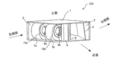
- FIG. 1 is a diagram for explaining the arrangement configuration of the control box 6 and the like of the indoor unit 100 of the air conditioner according to the first embodiment.
- the housing 1 of the indoor unit 100 includes a suction port 2, an air outlet 3, a heat exchanger 4, a partition plate 5, a control box 6, a first fan case 7a, and a first. 2
- a fan case 7b is provided.
- the housing 1 has a rectangular parallelepiped shape, and an air suction port 2 outside the housing 1 is provided on the left side surface of the housing 1 when viewed from the front side. Further, an air outlet 3 is provided on the right side surface of the housing 1.
- the air sucked from the suction port 2 is blown toward the right side by the first fan 9a housed in the first fan case 7a and the second fan 9b housed in the second fan case 7b.
- the blown air passes through the partition plate 5 and the heat exchanger 4, and is blown from the air outlet 3. That is, as shown by the arrow in FIG. 1, the air sucked from the suction port 2 provided on the left side surface of the housing 1 and heat-exchanged by the heat exchanger 4 is provided on the right side surface of the housing 1.
- the air is blown from the air outlet 3.
- the first fan case 7a and the second fan case 7b are arranged in the housing 1.
- the first fan case 7a and the second fan case 7b are arranged in the housing 1 with a predetermined interval in the lateral direction of the housing 1.
- a first fan case suction port 10a is provided on the front side of the first fan case 7a.
- the first fan case suction port 10a is for sucking the air sucked from the suction port 2 into the first fan case 7a.
- a second fan case suction port 10b is provided on the front side of the second fan case 7b.
- the second fan case suction port 10b is for sucking the air sucked from the suction port 2 into the second fan case 7b.
- the positions where the first fan case suction port 10a and the second fan case suction port 10b are provided are not limited to the front side of the first fan case 7a and the second fan case 7b.
- the positions of the first fan case suction port 10a and the second fan case suction port 10b may be provided on the back side of the first fan case suction port 10a and the second fan case suction port 10b.
- the positions of the first fan case suction port 10a and the second fan case suction port 10b may be provided on both the front side and the back side.
- the positions of the first fan case suction port 10a and the second fan case suction port 10b may be provided on at least one of the left side surface side and the right side surface side.
- FIG. 2 is a diagram showing a state in which the first fan case 7a and the second fan case 7b of the indoor unit 100 of the air conditioner according to the first embodiment are viewed from the right side.
- a first fan case outlet 11a and a second fan case outlet 11b are provided in the lower portion of the first fan case 7a and the second fan case 7b on the right side surface side, respectively. That is, the air passage of the air blown from the first fan case 7a and the second fan case 7b is on the lower side of the housing 1.
- the shapes of the first fan case outlet 11a and the second fan case outlet 11b do not matter.
- the first fan case 7a and the second fan case 7b are, for example, elliptical bell mouths.
- the first fan 9a is installed in the first fan case 7a.
- the first fan 9a is connected to a first fan motor (not shown) that rotates the first fan 9a.
- the second fan 9b is installed in the second fan case 7b.
- the second fan 9b is connected to a second fan motor (not shown) that rotates the second fan 9b.
- the first fan 9a and the second fan 9b are, for example, sirocco type fans.
- the first fan motor and the second fan motor include an inverter (not shown) that converts DC power into AC power.
- the control box 6 is arranged on the downstream side of the air flow from the first fan case suction port 10a and the second fan case suction port 10b. Further, the control box 6 partitions the portion other than the region connecting the first fan case outlet 11a to the first opening 5a of the partition plate 5 in the longitudinal direction and the horizontal direction of the housing 1 and the second fan case outlet 11b.
- the second opening 5b of the plate 5 is arranged in a portion other than the region connecting the housing 1 in the longitudinal direction and the horizontal direction. That is, it is a portion other than the air passage of the air blown from the first fan case outlet 11a and the second fan case outlet 11b, and the first fan case suction port 10a and the second fan case of the first fan case 7a. It is arranged on the downstream side of the air passage from the second fan case suction port 10b of 7b.
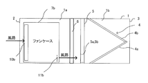
- FIG. 3 shows a case where the first fan case 7a, the second fan case 7b, the control box 6, the partition plate 5, and the heat exchanger 4 of the indoor unit 100 of the air conditioner according to the first embodiment are viewed from the front side. It is a figure for demonstrating the arrangement structure.
- FIG. 4 shows a case where the first fan case 7a, the second fan case 7b, the control box 6, the partition plate 5, and the heat exchanger 4 of the indoor unit 100 of the air conditioner according to the first embodiment are viewed from the upper surface side. It is a figure for demonstrating the arrangement structure.
- a first fan case suction port 10a is provided on the front side surface of the first fan case 7a.
- a second fan case suction port 10b is provided on the front side surface of the second fan case 7b.
- a partition plate 5 is arranged on the downstream side of the air passage of the air blown from the first fan case outlet 11a of the first fan case 7a and the second fan case outlet 11b of the second fan case 7b.
- FIG. 7 is a view of the partition plate 5 of the indoor unit 100 of the air conditioner according to the first embodiment as viewed from the side surface of the housing 1 on the air outlet 3 side.
- the partition plate 5 has a first opening 5a and a second opening 5b at the lower part.
- the first opening 5a is provided at a position corresponding to the air passage of the air blown out from the first fan case outlet 11a.
- the size of the first opening 5a is formed to be sufficiently large so that the air blown out from the first fan case outlet 11a is not damaged by the air passage pressure.
- the second opening 5b is provided at a position corresponding to the air passage of the air blown out from the second fan case outlet 11b.
- the size of the second opening 5b is formed to be sufficiently large so that the air blown out from the second fan case outlet 11b does not cause air passage pressure loss.
- the shapes of the first opening 5a and the second opening 5b do not matter.
- the partition plate 5 is attached to the inside of the housing 1 in addition to the first opening 5a and the second opening 5b so that the air in the fan case space 1a does not pass through the heat exchanger space 1b.
- the control box 6 has a rectangular parallelepiped shape and has a control unit 6a inside.
- the control unit 6a controls the first fan motor and the second fan motor of the indoor unit 100, as well as a compressor, a four-way valve, an expansion valve, a fan, and the like of an outdoor unit (not shown) arranged outside the unit.
- the control unit 6a is composed of dedicated hardware or a CPU (also referred to as a central processing unit, a processing unit, an arithmetic unit, a microprocessor, a microprocessor, or a processor) that executes a program stored in a memory. ..
- control unit 6a When the control unit 6a is dedicated hardware, the control unit 6a corresponds to, for example, a single circuit, a composite circuit, an ASIC (Application Specific Integrated Circuit), an FPGA (Field Programmable Gate Array), or a combination thereof. To do.
- Each of the functional units realized by the control unit 6a may be realized by individual hardware, or each functional unit may be realized by one hardware.
- control unit 6a When the control unit 6a is a CPU, each function executed by the control unit 6a is realized by software, firmware, or a combination of software and firmware. Software and firmware are written as programs and stored in memory. The CPU realizes each function of the control unit 6a by reading and executing the program stored in the memory.
- the memory is a non-volatile or volatile semiconductor memory such as a RAM, a ROM, a flash memory, an EPROM, or an EEPROM.
- the control box 6 is arranged in the vicinity of the partition plate 5 inside the housing 1.
- the control box 6 is arranged on the downstream side of the air flow from the first fan case suction port 10a and the second fan case suction port 10b. Further, the control box 6 is arranged in a portion other than the region connecting the first fan case outlet 11a to the first opening 5a of the partition plate 5 in the longitudinal direction and the horizontal direction of the housing 1. Further, the control box 6 is arranged in a portion other than the region connecting the second fan case outlet 11b to the second opening 5b of the partition plate 5 in the longitudinal direction and the horizontal direction of the housing 1.
- the fan case space 1a is a space inside the housing 1 in which the first fan case 7a and the second fan case 7b partitioned by the partition plate 5 are arranged.
- the mounting position of the control box 6 to the housing 1 is not limited to the position shown in FIG.
- the control box 6 is attached to the housing 1 at the suction port 2 of the housing 1, the first fan case suction port 10a of the first fan case 7a, and the second fan case suction port 10b of the second fan case 7b. It is placed in a part other than the air passage between them. Further, the mounting position of the control box 6 to the housing 1 is the air passage between the first fan case outlet 11a and the first opening 5a of the partition plate 5, and the second fan case outlet 11b and the partition plate 5.
- the control box 6 may be arranged on the front side or the back side of the fan case space 1a.
- FIG. 5 is a diagram for explaining a case where the control box 6 of the indoor unit 100 of the air conditioner according to the first embodiment is arranged on the front side.
- FIG. 6 is a diagram for explaining a case where the control box 6 of the indoor unit 100 of the air conditioner according to the first embodiment is arranged on the front side of the second fan case 7b.
- control box 6 is on the side surface side (front side of the housing 1) of the second fan case 7b, and is between the second fan case suction port 10b and the second fan case outlet 11b. Be placed.
- the position of such a control box 6 has a slower air flow than the position of the control box 6 shown in FIGS. 4 and 5. Therefore, the air passage resistance of the control box 6 can be reduced most efficiently.
- the control box 6 includes an air passage and a second air passage between the suction port 2 of the housing 1 and the first fan case suction port 10a of the first fan case 7a and the second fan case suction port 10b of the second fan case 7b.
- the heat exchanger 4 exchanges heat between the air that has passed through the first opening 5a and the second opening 5b of the partition plate 5 and the refrigerant that flows in the piping (not shown) of the heat exchanger 4.
- the heat exchanger 4 is arranged obliquely in the front-rear direction in the housing 1.
- the air that has passed through the heat exchanger 4 is blown out from the air outlet 3 provided on the right side surface of the housing 1.
- the control box 6 is the suction port 2 of the housing 1 and the first fan case suction port 10a and the second fan case 7b of the first fan case 7a. It is arranged in a portion other than the air passage between the second fan case and the suction port 10b. Further, the control box 6 includes other than the air passage between the first fan case outlet 11a and the first opening 5a of the partition plate 5, and the second fan case outlet 11b and the second opening 5b of the partition plate 5.
- the position where the control box 6 is arranged is that the air flow is slower than the upstream side of the first fan case suction port 10a of the first fan case 7a and the second fan case suction port 10b of the second fan case 7b. Therefore, the resistance of the air passage of the control box 6 can be reduced in the housing 1 of the indoor unit 100, and as a result, the air blown by the blower can be reduced.
- Embodiment 2 The indoor unit 100 of the air conditioner according to the second embodiment is a modified form of the heat exchanger 4.
- FIG. 8 shows a case where the first fan case 7a, the second fan case 7b, the control box 6, the partition plate 5, and the heat exchanger 4 of the indoor unit 100 of the air conditioner according to the second embodiment are viewed from the front side. It is a figure for demonstrating the arrangement structure.
- the heat exchanger 4 of the indoor unit 100 includes a first heat exchanger 4a and a second heat exchanger 4b.
- the first heat exchanger 4a is arranged diagonally from the lower surface near the partition plate 5 of the housing 1 to the central portion of the housing 1.
- the second heat exchanger 4b is arranged obliquely from the end side of the first heat exchanger 4a in the central portion of the housing 1 to the upper surface near the partition plate 5 of the housing 1.
- the vertical cross section from the upper surface to the lower surface of the housing 1 of the heat exchanger 4 composed of the first heat exchanger 4a and the second heat exchanger 4b is a partition plate when viewed from the air outlet 3 side of the housing 1. It has a V-shape that is open to 5.
- the indoor unit 100 of the air conditioner according to the second embodiment can increase the heat transfer area by arranging the V-shaped heat exchanger 4.
- the first fan 9a and the second fan 9b of the first embodiment and the second embodiment are also referred to as fans, and the first fan case 7a and the second fan case 7b are also referred to as fan cases.
- the first fan case suction port 10a and the second fan case suction port 10b are also referred to as a fan case suction port
- the first fan case outlet 11a and the second fan case outlet 11b are also referred to as a fan case outlet.
- the embodiment is presented as an example and is not intended to limit the scope of the embodiment.
- the embodiment can be implemented in various other forms, and various omissions, replacements, and changes can be made without departing from the gist of the embodiment. These embodiments and variations thereof are included in the scope and gist of the embodiments.
- 1 housing 1a fan case space, 1b heat exchanger space, 2 suction port, 3 outlet, 4 heat exchanger, 4a first heat exchanger, 4b second heat exchanger, 5 partition plate, 5a first opening , 5b 2nd opening, 6 control box, 6a control unit, 7a 1st fan case, 7b 2nd fan case, 9a 1st fan, 9b 2nd fan, 10a 1st fan case suction port, 10b 2nd fan Case suction port, 11a 1st fan case outlet, 11b 2nd fan case outlet, 100 indoor unit.
Abstract
Description
実施の形態1に係る室内機は、例えば、電算室等に設置される室内機である。室内機の蒸発器、膨張手段である膨張弁と、図示しない圧縮機、四方弁及び凝縮器とが機外に配置され、冷媒配管により順次接続されて冷媒回路が構成される。
The indoor unit according to the first embodiment is, for example, an indoor unit installed in a computer room or the like. An evaporator and an expansion valve as an expansion means of the indoor unit, and a compressor, a four-way valve and a condenser (not shown) are arranged outside the machine and are sequentially connected by a refrigerant pipe to form a refrigerant circuit.
実施の形態2に係る空気調和装置の室内機100は、熱交換器4の形態を変更したものである。図8は、実施の形態2に係る空気調和装置の室内機100の第1ファンケース7a、第2ファンケース7b、制御箱6、仕切板5及び熱交換器4を正面側から見た場合の配置構成を説明するための図である。
The
Claims (5)
- 一方の側面に吸込口が設けられ、前記一方の側面に対向する他方の側面に吹出口が設けられた直方体形状の筐体と、
前記筐体の吸込口からの空気を吸い込むファンケース吸込口と、前記ファンケース吸込口から吸い込まれた空気を前記吹出口方向に吹き出すファンケース吹出口とを有するファンケースと、
前記ファンケースに収容されたファンと、
前記ファンケースに収容され、前記筐体の吸込口の空気を前記ファンケース吸込口より吸込み、吸い込んだ空気を前記ファンケース吹出口から前記仕切板の開口部を介して前記吹出口へ送風するファンと、
前記筐体に収容された熱交換器と、
前記ファンケースの前記ファンケース吹出口に対応する位置に開口部を有し、前記ファンケースと、前記熱交換器との間に配置された仕切板と、
前記ファンを制御する制御部を有する制御箱とを具備し、
前記制御箱は、前記ファンケース吸込口よりも前記空気の流れの下流側であって、かつ前記ファンケース吹出口を前記仕切板の前記開口部に前記筐体の長手方向と水平方向に繋ぐ領域以外の部分に配置される、
空気調和装置の室内機。 A rectangular parallelepiped housing having a suction port on one side surface and an air outlet on the other side surface facing the one side surface.
A fan case having a fan case suction port for sucking air from the suction port of the housing, and a fan case outlet for blowing air sucked from the fan case suction port in the direction of the air outlet.
With the fan housed in the fan case,
A fan housed in the fan case, sucking air from the suction port of the housing from the fan case suction port, and blowing the sucked air from the fan case outlet to the outlet through the opening of the partition plate. When,
The heat exchanger housed in the housing and
A partition plate having an opening at a position corresponding to the fan case outlet of the fan case and arranged between the fan case and the heat exchanger.
A control box having a control unit for controlling the fan is provided.
The control box is a region downstream of the fan case suction port and connecting the fan case outlet to the opening of the partition plate in the longitudinal direction and the horizontal direction of the housing. Placed in other parts,
Indoor unit of air conditioner. - 前記制御箱は、前記ファンケースの側面側であって、かつ前記ファンケース吸込口と前記ファンケース吹出口との間に配置される、
請求項1記載の空気調和装置の室内機。 The control box is arranged on the side surface side of the fan case and between the fan case suction port and the fan case outlet.
The indoor unit of the air conditioner according to claim 1. - 前記制御箱は、前記仕切板によって仕切られた前記ファンケースが配置されている側の前記筐体の内部のファンケース空間に配置される、
請求項1又は2に記載の空気調和装置の室内機。 The control box is arranged in the fan case space inside the housing on the side where the fan case partitioned by the partition plate is arranged.
The indoor unit of the air conditioner according to claim 1 or 2. - 前記熱交換器は、前記筐体の上面から下面に向かう垂直方向の断面が前記筐体の吹出口側からみてV字形状である、
請求項1~3のいずれか1項に記載の空気調和装置の室内機。 The heat exchanger has a V-shaped cross section in the vertical direction from the upper surface to the lower surface of the housing when viewed from the outlet side of the housing.
The indoor unit of the air conditioner according to any one of claims 1 to 3. - 前記ファンは、
第1ファンと、
第2ファンと
を有し、
前記ファンケースは、
前記第1ファンを収容する第1ファンケースと、
前記第1ファンケースと前記筐体の短手方向に所定間隔を存して配置され、前記第2ファンを収容する第2ファンケースとを具備する、
請求項1~4のいずれか1項に記載の空気調和装置の室内機。 The fan
With the first fan
Have a second fan
The fan case is
A first fan case for accommodating the first fan and
A second fan case is provided, which is arranged at a predetermined distance in the lateral direction of the first fan case and the housing and accommodates the second fan.
The indoor unit of the air conditioner according to any one of claims 1 to 4.
Priority Applications (3)
| Application Number | Priority Date | Filing Date | Title |
|---|---|---|---|
| GB2203656.0A GB2603321B (en) | 2019-12-17 | 2019-12-17 | Indoor unit for air-conditioning apparatus |
| PCT/JP2019/049394 WO2021124446A1 (en) | 2019-12-17 | 2019-12-17 | Air conditioning device indoor unit |
| JP2021565205A JP7241918B2 (en) | 2019-12-17 | 2019-12-17 | Indoor unit of air conditioner |
Applications Claiming Priority (1)
| Application Number | Priority Date | Filing Date | Title |
|---|---|---|---|
| PCT/JP2019/049394 WO2021124446A1 (en) | 2019-12-17 | 2019-12-17 | Air conditioning device indoor unit |
Publications (1)
| Publication Number | Publication Date |
|---|---|
| WO2021124446A1 true WO2021124446A1 (en) | 2021-06-24 |
Family
ID=76477273
Family Applications (1)
| Application Number | Title | Priority Date | Filing Date |
|---|---|---|---|
| PCT/JP2019/049394 WO2021124446A1 (en) | 2019-12-17 | 2019-12-17 | Air conditioning device indoor unit |
Country Status (3)
| Country | Link |
|---|---|
| JP (1) | JP7241918B2 (en) |
| GB (1) | GB2603321B (en) |
| WO (1) | WO2021124446A1 (en) |
Citations (1)
| Publication number | Priority date | Publication date | Assignee | Title |
|---|---|---|---|---|
| WO2017056152A1 (en) * | 2015-09-28 | 2017-04-06 | 三菱電機株式会社 | Indoor unit |
Family Cites Families (1)
| Publication number | Priority date | Publication date | Assignee | Title |
|---|---|---|---|---|
| JP2010151399A (en) | 2008-12-26 | 2010-07-08 | Kubota Corp | Fan device supporting structure for air conditioner |
-
2019
- 2019-12-17 JP JP2021565205A patent/JP7241918B2/en active Active
- 2019-12-17 WO PCT/JP2019/049394 patent/WO2021124446A1/en active Application Filing
- 2019-12-17 GB GB2203656.0A patent/GB2603321B/en active Active
Patent Citations (1)
| Publication number | Priority date | Publication date | Assignee | Title |
|---|---|---|---|---|
| WO2017056152A1 (en) * | 2015-09-28 | 2017-04-06 | 三菱電機株式会社 | Indoor unit |
Also Published As
| Publication number | Publication date |
|---|---|
| GB202203656D0 (en) | 2022-04-27 |
| GB2603321B (en) | 2023-09-06 |
| JPWO2021124446A1 (en) | 2021-06-24 |
| JP7241918B2 (en) | 2023-03-17 |
| GB2603321A (en) | 2022-08-03 |
Similar Documents
| Publication | Publication Date | Title |
|---|---|---|
| JP5761097B2 (en) | Air conditioner indoor unit | |
| WO2015182461A1 (en) | Air conditioning indoor equipment | |
| JP2007120900A (en) | Closing valve-supporting member, and outdoor unit of air conditioner comprising the same | |
| JP5012260B2 (en) | Duct fan | |
| US11209175B2 (en) | Outdoor unit for refrigeration apparatus | |
| JP6038328B2 (en) | Air conditioner indoor unit | |
| CN210921594U (en) | Attachment and air conditioner including the same | |
| WO2020059006A1 (en) | Refrigeration cycle device | |
| JP7030489B2 (en) | air conditioner | |
| CN104864494A (en) | Indoor unit of air conditioner | |
| JP2023071327A (en) | indoor unit | |
| WO2019171462A1 (en) | Indoor unit and air conditioner | |
| WO2021124446A1 (en) | Air conditioning device indoor unit | |
| JP6848956B2 (en) | Indoor unit of air conditioner | |
| WO2016170652A1 (en) | Indoor unit and air conditioning device | |
| JP3876864B2 (en) | Indoor unit of air conditioner | |
| JP5743685B2 (en) | Refrigeration air conditioning system | |
| JP2015175557A (en) | duct type air conditioner | |
| CN111433520B (en) | Heat exchange unit and air conditioner equipped with heat exchange unit | |
| WO2017017851A1 (en) | Indoor unit of air conditioners | |
| JP2017215091A (en) | Indoor machine of air conditioner | |
| JP2022050948A (en) | Air conditioning ventilation system | |
| WO2018163360A1 (en) | Air conditioner indoor unit | |
| JP6758280B2 (en) | Air-conditioning indoor unit for computer room | |
| JP2010216750A (en) | Air conditioner |
Legal Events
| Date | Code | Title | Description |
|---|---|---|---|
| 121 | Ep: the epo has been informed by wipo that ep was designated in this application |
Ref document number: 19956926 Country of ref document: EP Kind code of ref document: A1 |
|
| ENP | Entry into the national phase |
Ref document number: 2021565205 Country of ref document: JP Kind code of ref document: A |
|
| ENP | Entry into the national phase |
Ref document number: 202203656 Country of ref document: GB Kind code of ref document: A Free format text: PCT FILING DATE = 20191217 |
|
| NENP | Non-entry into the national phase |
Ref country code: DE |
|
| 122 | Ep: pct application non-entry in european phase |
Ref document number: 19956926 Country of ref document: EP Kind code of ref document: A1 |