WO2021112229A1 - 手術支援ロボット及びその制御方法 - Google Patents
手術支援ロボット及びその制御方法 Download PDFInfo
- Publication number
- WO2021112229A1 WO2021112229A1 PCT/JP2020/045270 JP2020045270W WO2021112229A1 WO 2021112229 A1 WO2021112229 A1 WO 2021112229A1 JP 2020045270 W JP2020045270 W JP 2020045270W WO 2021112229 A1 WO2021112229 A1 WO 2021112229A1
- Authority
- WO
- WIPO (PCT)
- Prior art keywords
- surgical instrument
- manipulator
- joint
- displacement amount
- linear motion
- Prior art date
Links
- 238000001356 surgical procedure Methods 0.000 title claims abstract description 54
- 238000000034 method Methods 0.000 title claims description 30
- 230000033001 locomotion Effects 0.000 claims abstract description 114
- 238000006073 displacement reaction Methods 0.000 claims abstract description 81
- 230000000452 restraining effect Effects 0.000 claims 2
- 230000036544 posture Effects 0.000 description 20
- 210000000707 wrist Anatomy 0.000 description 19
- 238000010586 diagram Methods 0.000 description 14
- 230000004048 modification Effects 0.000 description 9
- 238000012986 modification Methods 0.000 description 9
- 210000003857 wrist joint Anatomy 0.000 description 9
- 230000004044 response Effects 0.000 description 7
- 230000005540 biological transmission Effects 0.000 description 5
- 230000007246 mechanism Effects 0.000 description 5
- 230000006870 function Effects 0.000 description 3
- 238000003780 insertion Methods 0.000 description 3
- 230000037431 insertion Effects 0.000 description 3
- 238000003860 storage Methods 0.000 description 3
- 239000003638 chemical reducing agent Substances 0.000 description 2
- 230000008569 process Effects 0.000 description 2
- 210000001124 body fluid Anatomy 0.000 description 1
- 239000010839 body fluid Substances 0.000 description 1
- 238000004140 cleaning Methods 0.000 description 1
- 238000004891 communication Methods 0.000 description 1
- 238000005520 cutting process Methods 0.000 description 1
- 238000002324 minimally invasive surgery Methods 0.000 description 1
- 238000002360 preparation method Methods 0.000 description 1
- 238000012545 processing Methods 0.000 description 1
- 239000000523 sample Substances 0.000 description 1
- 230000001629 suppression Effects 0.000 description 1
Images


Classifications
-
- B—PERFORMING OPERATIONS; TRANSPORTING
- B25—HAND TOOLS; PORTABLE POWER-DRIVEN TOOLS; MANIPULATORS
- B25J—MANIPULATORS; CHAMBERS PROVIDED WITH MANIPULATION DEVICES
- B25J9/00—Programme-controlled manipulators
- B25J9/16—Programme controls
- B25J9/1679—Programme controls characterised by the tasks executed
- B25J9/1689—Teleoperation
-
- A—HUMAN NECESSITIES
- A61—MEDICAL OR VETERINARY SCIENCE; HYGIENE
- A61B—DIAGNOSIS; SURGERY; IDENTIFICATION
- A61B34/00—Computer-aided surgery; Manipulators or robots specially adapted for use in surgery
- A61B34/30—Surgical robots
- A61B34/37—Master-slave robots
-
- A—HUMAN NECESSITIES
- A61—MEDICAL OR VETERINARY SCIENCE; HYGIENE
- A61B—DIAGNOSIS; SURGERY; IDENTIFICATION
- A61B17/00—Surgical instruments, devices or methods, e.g. tourniquets
- A61B17/34—Trocars; Puncturing needles
-
- A—HUMAN NECESSITIES
- A61—MEDICAL OR VETERINARY SCIENCE; HYGIENE
- A61B—DIAGNOSIS; SURGERY; IDENTIFICATION
- A61B34/00—Computer-aided surgery; Manipulators or robots specially adapted for use in surgery
- A61B34/70—Manipulators specially adapted for use in surgery
- A61B34/75—Manipulators having means for prevention or compensation of hand tremors
-
- A—HUMAN NECESSITIES
- A61—MEDICAL OR VETERINARY SCIENCE; HYGIENE
- A61B—DIAGNOSIS; SURGERY; IDENTIFICATION
- A61B90/00—Instruments, implements or accessories specially adapted for surgery or diagnosis and not covered by any of the groups A61B1/00 - A61B50/00, e.g. for luxation treatment or for protecting wound edges
- A61B90/50—Supports for surgical instruments, e.g. articulated arms
-
- A—HUMAN NECESSITIES
- A61—MEDICAL OR VETERINARY SCIENCE; HYGIENE
- A61B—DIAGNOSIS; SURGERY; IDENTIFICATION
- A61B34/00—Computer-aided surgery; Manipulators or robots specially adapted for use in surgery
- A61B34/30—Surgical robots
- A61B2034/302—Surgical robots specifically adapted for manipulations within body cavities, e.g. within abdominal or thoracic cavities
-
- G—PHYSICS
- G05—CONTROLLING; REGULATING
- G05B—CONTROL OR REGULATING SYSTEMS IN GENERAL; FUNCTIONAL ELEMENTS OF SUCH SYSTEMS; MONITORING OR TESTING ARRANGEMENTS FOR SUCH SYSTEMS OR ELEMENTS
- G05B2219/00—Program-control systems
- G05B2219/30—Nc systems
- G05B2219/45—Nc applications
- G05B2219/45117—Medical, radio surgery manipulator
Definitions
- the present invention relates to a surgery support robot.
- Robot-assisted surgery systems generally include surgical instruments (slave devices) that have surgical instruments and manipulators that support them, master devices that are directly operated by the surgeon, and surgical instruments that correspond to the operations received by the master device. It is equipped with a control device that controls a surgical instrument and a manipulator so that it can move.
- Patent Document 1 discloses this type of robot-assisted surgery system.
- the robot-assisted surgery system of Patent Document 1 includes a surgeon console and a patient-side cart (an example of a surgery support robot) remotely controlled by the surgeon console.
- the patient-side cart comprises a plurality of manipulator arms and surgical instruments interchangeably coupled to instrument holders provided at the distal ends of each manipulator arm.
- the surgical instrument includes a base portion connected to the instrument holder, an elongated shaft portion connected to the base portion, and a tool portion connected to the distal end portion of the shaft portion.
- a cannula (or trocar sleeve) is placed in the minimally invasive incision of the patient's body wall, the shaft is passed through the cannula, and the tool is inserted into the patient's body cavity through the cannula.
- Patent Document 1 describes that the movement of the surgical instrument is restrained so that the shaft portion of the surgical instrument pivots around the remote center during the operation by the robot.
- the remote center is set at or near the minimally invasive incision (or the cannula placed therein) so that the size of the minimally invasive incision can be minimized.
- the cannula and the surgical instrument are supported by one instrument holder of the manipulator arm so that the minimally invasive incision and the remote center can be aligned by using the cannula, and the instrument holder is used.
- the linear slide of the surgical instrument along the remote center allows the surgical instrument to be inserted into or out of the patient's body cavity through the remote center.
- the present invention it is possible to secure a wider working space around the surgical operation portion than the conventional surgical support robot, and it is possible to quickly perform the retracting operation of the tool portion of the surgical instrument from the body cavity. And its control method.
- the inside of the trocar placed on the body wall of the patient can be mentioned.
- the interior of the trocar can be the closest evacuation position to the tool section within the patient's body cavity.
- each manipulator has a degree of freedom of redundancy so that interference does not occur between a plurality of manipulators. Therefore, when a surgical instrument is inserted or removed into a patient's body cavity, multiple joints may operate instead of a single joint. However, when the tool part of the surgical instrument moves in the direction of retracting from the body cavity, only a single linear joint can operate in the manipulator due to the suppression of the swing of the shaft part passing through the trocar and the pursuit of speed. desirable.
- the surgery support robot is A surgical instrument having a base portion provided at the proximal end, a tool portion provided at the distal end, and a shaft portion extending in the axial direction with the direction connecting the base portion and the tool portion as the axial direction.
- It has an instrument interface to which the base is mounted, an arm containing a plurality of rotary joints, and a linear motion joint connecting the instrument interface to the distal end of the arm and is placed on the patient's body wall.
- a manipulator that supports the surgical instrument without holding a trocar, Equipped with a control device The control device is Memorize the remote center, which is the center of movement of the surgical instrument,
- the intracorporeal length of the surgical instrument from the remote center to the distal end of the surgical instrument is intracorporeally.
- the length is L
- the amount of linear displacement possible parallel to the axial direction from the origin position of the linear motion joint is T0
- the amount of linear displacement parallel to the axial direction from the origin position of the linear motion joint to the current position Is the first linear displacement amount T1, and when L ⁇ T0, the movement of the manipulator is controlled so that the relationship between L and T1 is T1 ⁇ L.
- the surgery support robot A surgical instrument having a base portion provided at the proximal end, a tool portion provided at the distal end, and a shaft portion extending in the axial direction with the direction connecting the base portion and the tool portion as the axial direction.
- It has an instrument interface to which the base is mounted, an arm containing a plurality of rotary joints, and a linear motion joint connecting the instrument interface to the distal end of the arm and is placed on the patient's body wall.
- the control method is A step to memorize the remote center, which is the center of movement of the surgical instrument.
- the intracorporeal length of the surgical instrument from the remote center to the distal end of the surgical instrument is intracorporeally.
- the length is L
- the linear displacement amount parallel to the axial direction from the origin position of the linear motion joint to the current position is defined as the first linear motion displacement amount T1
- the linear motion displacement amount is parallel to the axial direction from the origin position of the linear motion joint. It is characterized by including a step of controlling the movement of the manipulator so that the relationship between L and T1 is T1 ⁇ L when the linear displacement possible amount is T0 and L ⁇ T0.
- the tool portion of the surgical instrument can be retracted from the patient's body cavity only by controlling the linear motion joint of the manipulator to return to the origin position (retraction control).
- the shaft portion of the surgical instrument can be moved only in parallel with the axial direction.
- the runout of the shaft portion is suppressed, and galling is less likely to occur between the trocar and the shaft portion.
- the shaft portion can be smoothly pulled out from the trocar, so that the load on the body wall can be reduced.
- the trocar is not held by the instrument holder that supports the surgical instrument unlike the conventional operation support robot, so that the area around the operation portion is congested by a plurality of instrument holders. Is relaxed.
- the control device has a predetermined linear displacement amount parallel to the axial direction of the distal end portion of the arm due to the operation of at least one of the plurality of rotary joints. Is the second linear displacement amount T2, and when L> T0, the movement of the manipulator may be controlled so that the relationship between L, T1, and T2 is (T1 + T2) ⁇ L.
- a predetermined linear displacement amount parallel to the axial direction of the distal end portion of the arm due to the operation of at least one of the plurality of rotary joints is determined. 2
- the step of controlling the movement of the manipulator may be included so that the relationship between L, T1, and T2 is (T1 + T2) ⁇ L.
- the tool portion of the surgical instrument can be operated only by controlling the linear motion joint of the manipulator to return to the origin position and rotating at least one rotary joint as needed (retraction control). It can be evacuated from the patient's body cavity.
- the work space around the surgical operation portion can be made wider than before, and the tool portion of the surgical instrument can be quickly retracted from the body cavity.
- FIG. 1 is a plan view showing the overall configuration of a surgical system including a surgical support robot according to an embodiment of the present invention.
- FIG. 2 is a side view of the surgery support robot.
- FIG. 3 is a diagram showing a shaft configuration of a manipulator and a surgical instrument.
- FIG. 4 is a plan view showing the overall configuration of the surgical system including the surgical support robot according to the first modification.
- FIG. 5 is a side view of the surgery support robot according to the first modification.
- FIG. 6 is a diagram showing a shaft configuration of a manipulator and a surgical instrument of the surgical support robot according to the first modification.
- FIG. 7 is a diagram showing a configuration of a drive system of a positioner, a manipulator, and a surgical instrument.
- FIG. 1 is a plan view showing the overall configuration of a surgical system including a surgical support robot according to an embodiment of the present invention.
- FIG. 2 is a side view of the surgery support robot.
- FIG. 3 is a diagram showing
- FIG. 8 is a diagram showing a configuration of a control system of a surgical system.
- FIG. 9 is a diagram showing a configuration of a command unit (processor).
- FIG. 10 is a diagram showing a state of the surgical instrument in the retracted position.
- FIG. 11 is a diagram showing a state of the surgical instrument at the insertion position.
- FIG. 12 is a diagram showing another aspect of the surgical instrument in the insertion position.
- FIG. 1 is a plan view showing the overall configuration of the surgery system 100 including the surgery support robot 1A according to the first embodiment of the present invention.
- the surgery system 100 shown in FIG. 1 includes a surgery support robot 1A which is a patient-side system and a console 2 which is a surgeon-side system.
- the console 2 is a device that receives input of operations from the surgeon 203 to the surgical system 100.
- the console 2 is for remotely operating the surgery support robot 1A, and is installed in the operating room or outside the operating room.
- the console 2 includes a plurality of operation input tools, a monitor 24, and a console control device 25.
- the plurality of operation input tools include at least one of an operation manipulator arm 21, an operation pedal 22, a touch panel display, an operation button, an operation lever, and the like.
- the console control device 25 causes the monitor 24 to display an image taken by the endoscope 29 (see FIG. 8), which is one of the surgical instruments 4.
- the surgeon 203 operates the operation input tool while visually recognizing the affected part (treatment site) displayed on the monitor 24.
- the console control device 25 acquires the input of the operation received by the operation input tool, and transmits it to the robot control device 6 described later via a wire or wireless.
- the surgery support robot 1A is arranged in the operating room beside the operating table 202 on which the patient 201 lies.
- the operating room is a sterilized field.
- FIG. 2 is a side view of the surgery support robot 1A.
- the surgery support robot 1A shown in FIGS. 1 and 2 is detachably attached to the carriage 9, the positioner 7 supported by the carriage 9, the platform 5 connected to the distal end of the positioner 7, and the platform 5. It includes a plurality of patient-side manipulators (hereinafter, simply referred to as "manipulators 3"), a surgical instrument 4 attached to the distal end of each manipulator 3, and a robot control device 6.
- the elements from the trolley 9 to the surgical instrument 4 are connected in a series.
- the end portion on the side facing the carriage 9 is referred to as a "proximal end portion”
- distal end portion on the opposite side thereof is referred to as a "distal end portion”.
- the bogie 9 includes a bogie body 91, front wheels 92, rear wheels 93, and a handle 94.
- the surgeon 203 or the surgical assistant can grasp the handle 94 and steer the trolley 9, and move the surgical support robot 1A to an arbitrary position.
- the dolly 9 during the operation is fixed in position.
- the positioner 7 is configured as a 7-axis vertical articulated robot arm.
- the positioner 7 moves the position of the platform 5 three-dimensionally with respect to the carriage 9.
- the aspect of the positioner 7 is not limited to this embodiment, and a vertical articulated robot arm, a horizontal articulated robot arm, or the like other than the seven axes can be adopted as the positioner 7.
- the positioner 7 includes a base 70 mounted on the carriage 9 and a plurality of connected positioner links 71 to 76.
- the plurality of positioner links 71 to 76 are rotatably connected to the base 70 via the first joint J71, and swayably connected to the first link 71 via the second joint J72.
- the second link 72, the third link 73 swingably connected to the second link 72 via the third joint J73, and the fourth link 74 rotatably connected to the third link 73 via the fourth joint J74.
- the fifth link 75 oscillatingly connected to the fourth link 74 via the fifth joint J75, the sixth link 76 rotatably connected to the fifth link 75 via the sixth joint J76, and A mechanical interface 77 rotatably connected to the sixth link 76 via a seventh joint J77 is included.
- the platform 5 is connected to the mechanical interface 77.
- the platform 5 functions as a hub that serves as a base for a plurality of manipulators 3.
- the combination of the carriage 9, the positioner 7, and the platform 5 constitutes a manipulator support that movably supports a plurality of manipulators 3.
- the platform 5 includes a main body 50, a positioner connecting portion 51 provided at the proximal end of the main body 50, and a plurality of manipulator connecting portions 52 provided at the distal end of the main body 50.
- the positioner connecting portion 51 is connected to the mechanical interface 77 of the positioner 7.
- the main body 50 has an arch shape having a certain longitudinal direction and the longitudinal direction is the extending direction of the strings.
- the plurality of manipulator connecting portions 52 are dispersedly arranged in the longitudinal direction of the main body 50. In the present embodiment, four manipulator connecting portions 52 are provided. A proximal end of the manipulator 3 is detachably connected to each manipulator connecting portion 52.
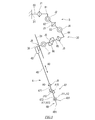
- FIG. 3 is a diagram showing a shaft configuration of the manipulator 3 and the surgical instrument 4.
- the manipulator 3 has a first interface 31 provided at the proximal end, a second interface 36 (instrument interface) provided at the distal end, and a first interface 31. It is provided with an arm 30 that connects between the second interface 36 and the second interface 36.
- the first interface 31 is connected to the manipulator connecting portion 52 of the platform 5.
- a surgical instrument 4 including an endoscope 29 is connected to a second interface 36 of one of the plurality of manipulators 3.
- a surgical instrument 4 for surgery is connected to at least one second interface 36 of the plurality of manipulators 3.
- the arm 30 includes a base 80 having a first interface 31 and a plurality of connected arm links 81 to 86.
- the plurality of arm links 81 to 86 are rotatably connected to the base 80 via the first joint J1 and swingably connected to the first link 81 via the second joint J2.
- the second link 82, the third link 83 rotatably connected to the second link 82 via the third joint J3, and the fourth link 84 swingably connected to the third link 83 via the fourth joint J4.
- the fifth link 85 rotatably connected to the fourth link 84 via the fifth joint J5, and the sixth link 86 swingably connected to the fifth link 85 via the sixth joint J6.
- a linear motion frame 35 is swingably connected to the sixth link 86 via a seventh joint J7.
- the second interface 36 is connected to the linear motion frame 35 via the eighth joint J8.
- the eighth joint J8 is a linear motion joint that connects the second interface 36 to the linear motion frame 35 so as to be linearly movable.
- the eighth joint J8 has a rail portion 61 provided on the linear motion frame 35 and a slider portion 62 that travels while being guided by the rail portion 61.
- the slider portion 62 is coupled to the second interface 36.
- the surgical instrument 4 has a base portion 45 provided at the proximal end, a tool portion 48 provided at the distal end, and a shaft portion 46 connecting the base portion 45 and the tool portion 48.
- a wrist portion 47 is interposed between the shaft portion 46 and the tool portion 48.
- the base portion 45 is detachably attached to the second interface 36 of the manipulator 3.
- the shaft portion 46 is an elongated and hard tubular member, and extends in a certain axial direction A0.
- the extension direction of the rail portion 61 and the axial direction A0 of the surgical instrument 4 are parallel. Therefore, when the slider portion 62 travels on the rail portion 61, the surgical instrument 4 moves in the axial direction A0 with respect to the linear motion frame 35.
- the wrist unit 47 has at least one wrist joint.
- the wrist portion 47 of the surgical instrument 4 illustrated in FIG. 3 includes a first wrist link 471, a second wrist link 472, a first wrist joint J9 connecting the shaft portion 46 and the first wrist link 471, and a first wrist link. It has a second wrist joint J10 that connects the 471 and the second wrist link 472, and a third wrist joint J11 that connects the second wrist link 472 and the tool portion 48.
- the first wrist joint J9 rotates the first wrist link 471 with respect to the base portion 45 about the first axis A9.
- the first axis A9 passes through the axis of the shaft portion 46 and is parallel to the axial direction A0 of the surgical instrument 4.
- the second wrist joint J10 rotates the second wrist link 472 with respect to the first wrist link 471 about the second axis A10.
- the second axis A10 is substantially orthogonal to the first axis A9.
- the third wrist joint J11 rotates the tool portion 48 about the third axis A11.
- the third axis A11 is substantially orthogonal to the first axis A9 and the second axis A10.
- the tool portion 48 according to the present embodiment is a forceps and has a pair of jaw members 481.
- the tool portion 48 has a tool joint J12 that rotates a pair of jaw members 481 about a third axis A11.
- the tool joint J12 opens and closes the jaws of the forceps by rotating the pair of jaw members 481 in opposite directions.
- FIG. 4 is a plan view showing the overall configuration of the surgery system 100 including the surgery support robot 1B according to the modification 1
- FIG. 5 is a side view of the surgery support robot 1B according to the modification 1.
- FIG. FIG. 6 is a diagram showing an axial configuration of the manipulator 3 and the surgical instrument 4 of the surgical support robot 1B according to the modified example 1.
- the same members as those in the above-described embodiment are designated by the same reference numerals in the drawings, and the description thereof will be omitted.
- the surgery support robot 1B according to the modified example 1 has a carriage 9, a positioner 7 supported by the carriage 9, and a positioner 7 as in the operation support robot 1A according to the above embodiment.
- a platform 5 connected to the distal end, a plurality of manipulators 3 detachably attached to the platform 5, a surgical instrument 4 attached to the distal end of each manipulator 3, and a robot control device 6.
- the bases of the plurality of manipulators 3 are connected to the rear surface of the platform 5, whereas in the surgery support robot 1B according to the modification 1, the bases of the plurality of manipulators 3 are platforms. The difference is that it is connected to the front of 5. As shown in FIGS.
- the rear surface of the platform 5 is the surface of the platform 5 facing the direction in which the handle 94 of the trolley 9 is located in the reference postures of the surgery support robots 1A and 1B.
- the front surface of the platform 5 is a surface facing the rear surface of the platform 5 and the opposite side.
- the operation support robot 1A and the operation support robot 1B according to the modified example 1 have different extension directions of the first link 81 of the plurality of manipulators 3 with respect to the platform 5. Therefore, as shown in FIG. 6, the first link The standard postures of 81, the second link 82, and the second joint J2 connecting them are different, but except for this point, the axial configuration of the manipulator 3 and the surgical instrument 4 of the surgical support robot 1B according to the first modification. And the axial configurations of the manipulator 3 and the surgical instrument 4 of the surgical support robot 1A are substantially the same.
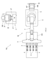
- FIG. 7 is a diagram showing a configuration of a drive system of the positioner 7, the manipulator 3, and the surgical instrument 4. Note that FIG. 7 shows the configuration of the drive system for one surgical instrument 4, and the configuration of the drive system for the other surgical instrument 4 is omitted.
- the positioner 7 has joint drive devices D71 to D77 corresponding to the joints J71 to J77.
- the operations of the joint drive devices D71 to D77 are controlled by the robot control device 6.
- the manipulator 3 has joint drive devices D1 to D8 corresponding to the joints J1 to J8.
- the joint drive device D8 of the eighth joint J8 is a slider drive unit that drives the slider unit 62.
- the operations of the joint drive devices D1 to D8 are controlled by the robot control device 6. Note that FIG. 7 shows the configuration of the drive system for one arm 30, and the configuration of the drive system for the other arm 30 is omitted.
- the surgical instrument 4 has joint drive devices D9 to D12 corresponding to each joint J9 to J12.
- the operations of the joint drive devices D9 to D12 are controlled by the robot control device 6.
- the joint drive device Dn includes a servomotor Mn, a rotation angle sensor En, a speed reducer Rn, and a power transmission mechanism (not shown).
- the rotation angle sensor En detects the rotation angle of the servomotor Mn and transmits it to the robot control device 6.
- the speed reducer Rn reduces the output of the servomotor Mn to amplify the torque.
- the power transmission mechanism transmits the output of the servomotor Mn to the corresponding link or the like.
- the power transmission mechanism may be composed of a plurality of gears, transmission wires, transmission belts, or a combination thereof.
- FIG. 8 is a diagram showing a configuration of a control system of the surgical system 100.
- the robot control device 6 includes a command unit 601 and a control unit 602.
- the command unit 601 generates an operation command signal
- the operation command includes a position command.
- the command unit 601 includes a processor 461, a memory 463 such as a ROM and a RAM, an I / O unit (input / output unit) 464, and a communication path for connecting these to each other.
- a storage device 462, a display 467, an operation input device 468, various sensors, a control unit 602, and the like are connected to the command unit 601 via an interface 465.
- the command unit 601 may include a single processor 461 that performs centralized control, or may include a plurality of processors 461 that perform distributed control.
- the command unit 601 is, for example, at least one of a computer, a personal computer, a microcontroller, a microprocessor, a PLD (programmable logic device) such as an FPGA (field-programmable gate array), a PLC (programmable logic controller), and a logic circuit. It may be composed of one or a combination of two or more.
- the memory 463 and the storage device 462 store basic programs, software programs, and the like executed by the processor 461. When the processor 461 reads and executes the program, the command unit 601 realizes the function configured in the software program.
- the memory 463 or the storage device 462 of the command unit 601 contains information on the surgical instrument 4, information on the surgical support robots 1A and 1B, information on the operating table 202, information on the console 2, information on the content of the surgery, and the like. , Various information necessary for robot-assisted surgery and its preparation is stored.
- the servo amplifier Cn is electrically connected to the servo motor Mn via an amplifier circuit, a converter, or the like (not shown).
- the servo amplifier Cn moves the servomotor Mn by obtaining the drive current of the joint Jn corresponding to the operation command and supplying the drive current to the servomotor Mn.
- the command unit 601 acquires the input of the operation related to the position and posture of the platform 5 from the operation input device 468 mounted on the operation support robots 1A and 1B.
- the command unit 601 obtains the position information and the rotation angle information of the joints J71 to J77 based on the motor rotation angles detected by the rotation angle sensors E71 to E77, and the positioner so that the platform 5 becomes the target position and posture.
- the positions and speeds of the joints J71 to J77 of No. 7 are obtained, and a position command is generated in response to the input of the acquired operation based on the positions and postures.
- the generated position command is transmitted to the control unit 602 (servo amplifiers C71 to C77).
- the control unit 602 that has acquired the position command generates a drive command value based on the motor rotation angle and the position command, and supplies the drive current corresponding to the drive command value to the servomotors M71 to M77.
- the joint drive devices D71 to D77 are activated to move the joints J71 to J77, and the platform 5 is in the position and posture in response to the operation.
- the command unit 601 acquires the input of the operation related to the position and posture of the surgical instrument 4 from the console control device 25.
- the command unit 601 obtains the position information and the rotation angle information of the joints J1 to J12 based on the motor rotation angles detected by the rotation angle sensors E1 to E12, and the tool unit 48 of the surgical instrument 4 sets the target position and posture.
- the positions and angles of rotation of the joints J1 to J12 are obtained, and a position command is generated in response to the input of the acquired operation based on the positions and angles of rotation.
- the generated position command is transmitted to the control unit 602 (servo amplifiers C1 to C12).
- the control unit 602 that has acquired the position command generates a drive command value based on the motor rotation angle and the position command, and supplies the drive current corresponding to the drive command value to the servomotors M1 to M12.
- the joint drive devices D1 to D12 are activated to move the joints J1 to J12, and the tool portion 48 of the surgical instrument 4 is in the position and posture in response to the operation.
- the trolleys 9 of the surgery support robots 1A and 1B are carried to the vicinity of the operating table 202, and the positioner 7 and each manipulator 3 are deployed to a predetermined preset position.
- a teaching tool (not shown) is connected to the second interface 36 of the manipulator 3.
- the teaching tool imitates the surgical instrument 4 and has an interface connected to the second interface 36 like the surgical instrument 4.
- the teaching tool is for teaching the remote center RC to the surgical support robots 1A and 1B.
- the operator applies an external force to the manipulator 3 to which the teaching tool is mounted (or operates the manipulator 3 via the operation input device 468) to move the teaching tool to a desired position.
- the robot control device 6 obtains the position information and the rotation angle information of the joints J1 to J12 based on the motor rotation angles detected by the rotation angle sensors E1 to E12, and further utilizes the characteristic information of the teaching tool and the like. Find the position of the teaching point specified in the teaching tool.
- the robot control device 6 obtains the position of the remote center RC by using the position of the teaching point and stores it in the memory 463.
- the remote center RC is the center of movement of the surgical instrument 4, and is usually set at or near the entrance 200in of the trocar 200 placed on the body wall 204 of the patient 201.
- the trocar 200 is a tube-shaped object that is placed on the body wall 204 of the patient 201 to form a surgical port.
- the trocar 200 has a sleeve through which the surgical instrument 4 is inserted.
- a tube-shaped object such as a cannula, a sleeve, or a tube may be used. In this way, the remote center RC is taught to the robot controller 6 prior to surgery.
- FIG. 10 is a diagram showing the state of the surgical instrument 4 in the retracted position from the body cavity 205.
- the entire tool portion 48 is located inside the trocar 200, or part or all of it is body from the trocar 200. It has escaped to the outside, and the tool portion 48 is not present in the body cavity 205 of the patient 201.
- the evacuation point EP as described above is set inside the trocar 200 placed on the body wall 204 of the patient 201.
- the evacuation point EP may be set at the inlet 200in or the outlet 200out of the trocar 200, but it is desirable that the evacuation point EP is set between the inlet 200in and the outlet 200out.
- the evacuation point EP may be set at the same position as the remote center RC.
- the robot control device 6 may set and store the evacuation point EP based on the position of the remote center RC.
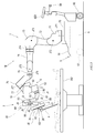
- FIG. 11 is a diagram showing the state of the surgical instrument 4 at the insertion position.
- the shaft portion 46 is passed through the trocar 200, and the tool portion 48 is located in the body cavity 205 of the patient 201.
- the distance from the remote center RC to the entrance 200in of the trocar 200 is defined as the distance ⁇ .
- ⁇ can be a constant.
- the value of ⁇ changes depending on the type of the trocar 200.
- the distance from the remote center RC to the exit 200 out of the trocar 200 is defined as the distance ⁇ .
- ⁇ can be a constant.
- the length from the remote center RC to the distal end of the surgical instrument 4 is the surgical instrument. It is referred to as "length L in the body cavity" of 4.
- the intrabody cavity length L of the surgical instrument 4 is determined based on an operation input by the surgeon 203 using the operating manipulator arm 21 of the console 2.
- the length of the wrist portion 47 included in the intrabody cavity length L is the length of the wrist portion 47 in the axial direction A0 when the surgical instrument 4 is in the reference posture. This length is substantially equal to the length passing through the central axis of the wrist portion 47.
- the length of the tool portion 48 included in the intrabody cavity length L is the length of the tool portion 48 in the axial direction A0 when the surgical instrument 4 is in the reference posture. That is, regardless of the current postures of the wrist unit 47 and the tool unit 48, the intrabody cavity length L of the surgical instrument 4 is calculated assuming that the surgical instrument 4 is virtually the reference posture.
- the intrabody cavity length L of the surgical instrument 4 can be obtained based on the position and posture of the second interface 36, the position of the remote center RC, and the external shape information of the surgical instrument 4.
- the external shape information of the surgical instrument 4 includes, for example, the size of the base portion 45, the length of the shaft portion 46, the link length of the wrist portion 47, and the length of the jaw member 481 of the tool portion 48.
- the position and orientation of the second interface 36 can be obtained based on the rotation angle detected by the rotation angle sensors E1 to E8 and the external shape information of the manipulator 3.
- the method for calculating the intrabody cavity length L of the surgical instrument 4 is not limited to the above.
- the origin position S0 and the end point position Se are defined in advance in the eighth joint J8 of the manipulator 3.
- the origin position S0 is defined at or near the proximal end of the rail portion 61.
- the end point position Se is defined at or near the distal end of the rail portion 61.
- the current traveling position of the slider unit 62 is referred to as "current position Sc”.
- the amount of displacement parallel to the axial direction A0 from the origin position S0 to the end point position Se of the eighth joint J8 is referred to as a "linear displacement possible amount T0" of the eighth joint J8.
- the amount of displacement parallel to the axial direction A0 from the origin position S0 to the current position Sc of the eighth joint J8 is referred to as the "first linear displacement amount T1" of the eighth joint J8.
- the first linear displacement amount T1 by the eighth joint J8 is the same as the intrabody cavity length L of the surgical instrument 4. It is maintained in a predetermined relationship.
- the robot control device 6 operates the eighth joint J8 so that the length L in the body cavity and the first linear displacement amount T1 are equal to each other.
- the robot control device 6 operates the joints J1 to J7 excluding the eighth joint J8 of the manipulator 3 and the joints J9 to J12 of the surgical instrument 4 so that the position and posture of the tool unit 48 correspond to the command. That is, the distal end of the surgical instrument 4 is moved to the position commanded only by the linear motion displacement of the eighth joint J8 in response to the movement command of the distal end of the surgical instrument 4 by the operating manipulator arm 21 in the axial direction A0.
- the robot control device 6 moves the surgical instrument 4 in the axial direction A0 using only the eighth joint J8 without using the plurality of rotary joints J1 to J7 of the manipulator 3.
- the robot control device 6 controls the evacuation of the patient 201 of the surgical instrument 4 from the body cavity 205 by using a given evacuation signal as a trigger.
- the evacuation signal can be generated by operating the evacuation operation tool 63 of the manipulator 3.
- the evacuation operation tool 63 is provided on each of the manipulators 3 of the surgery support robots 1A and 1B (see FIGS. 2 and 8).
- the retracting operation tool 63 may be, for example, a simple operating tool such as a button, a lever, or a pedal.
- an evacuation signal is given to the robot control device 6.
- the robot control device 6 performs evacuation control immediately after acquiring the evacuation signal. Specifically, the robot control device 6 moves (returns) the slider unit 62 from the current position Sc to the origin position S0 while maintaining the positions and rotation angles of the joints J1 to J7 of the manipulator 3. Operate joint J8. At the same time, the robot control device 6 operates the wrist joints J9 to J11 and the tool joints J12 of the surgical instrument 4 as necessary so that the surgical instrument 4 is in the reference posture.
- the shaft portion 46 of the surgical instrument 4 is pulled out from the trocar 200 in parallel with the axial direction A0, and the distal end portion of the surgical instrument 4 reaches the evacuation point EP.
- the tool portion 48 of the surgical instrument 4 is in a state of being retracted from the body cavity 205 of the patient 201.
- the surgical support robots 1A and 1B of the present embodiment include the surgical instrument 4 and the manipulator 3 that supports the surgical instrument 4 without holding the trocar 200 placed on the body wall 204 of the patient 201.
- the robot control device 6 is provided.
- the surgical instrument 4 has a base portion 45 provided at the proximal end, a tool portion 48 provided at the distal end, and an axial direction in which the direction connecting the base portion 45 and the tool portion 48 is the A0 axial direction. It has a shaft portion 46 extending to A0.
- the manipulator 3 includes an instrument interface 36 to which the base portion 45 is mounted, an arm 30 including a plurality of rotary joints (first joint J1 to seventh joint J7), and a linear motion joint connecting the instrument interface 36 and the arm 30. It has (8th joint J8).
- the intrabody cavity length L of the surgical instrument 4 represents the length from the remote center RC to the distal end of the surgical instrument 4.
- the first linear motion displacement amount T1 of the linear motion joint (8th joint J8) represents the displacement amount parallel to the axial direction A0 from the origin position S0 to the current position Sc of the linear motion joint (8th joint J8).
- the linear displacement possible amount T0 of the linear motion joint (8th joint J8) represents the displacement amount parallel to the axial direction A0 from the origin position S0 to the end point position Se of the linear motion joint (8th joint J8).
- control method of the surgery support robots 1A and 1B is as follows.
- the shaft portion 46 is passed through the trocar 200 and the tool portion 48 is in the body cavity 205 of the patient 201, the intrabody cavity length L of the surgical instrument 4 and the first linear motion of the linear motion joint (8th joint J8).
- It includes a step of controlling the movement of the manipulator 3 so that the relationship with the displacement amount T1 is T1 L.
- the robot control device 6 has a length L in the body cavity of the surgical instrument 4 when the shaft portion 46 is passed through the trocar 200 and the tool portion 48 is in the body cavity 205 of the patient 201.
- the movement of the manipulator 3 may be controlled so that the relationship between the linear motion joint (8th joint J8) and the first linear motion displacement amount T1 is T1 ⁇ L.
- the control method of the surgery support robots 1A and 1B is as follows.
- the shaft portion 46 is passed through the trocar 200 and the tool portion 48 is in the body cavity 205 of the patient 201, the intrabody cavity length L of the surgical instrument 4 and the first straight of the linear motion joint (8th joint J8).
- It may include a step of controlling the movement of the manipulator 3 so that the relationship with the dynamic displacement amount T1 is T1 ⁇ L.
- the relationship between the first linear displacement displacement T1 of the linear motion joint (8th joint J8), the distance ⁇ from the remote center RC to the entrance 200in of the trocar 200, and the distance ⁇ from the remote center RC to the exit 200out of the trocar 200 , (L ⁇ ) ⁇ T1 ⁇ (L + ⁇ ), the movement of the manipulator 3 may be controlled.
- the control method of the surgery support robots 1A and 1B is as follows.
- the shaft portion 46 is passed through the trocar 200 and the tool portion 48 is in the body cavity 205 of the patient 201, the length L in the body cavity of the surgical instrument 4 and the first linear motion of the linear motion joint (8th joint J8).
- the relationship between the displacement amount T1, the distance ⁇ from the remote center RC to the entrance 200in of the trocar 200, and the distance ⁇ from the remote center RC to the exit 200out of the trocar 200 is (L ⁇ ) ⁇ T1 ⁇ (L + ⁇ ).
- the first linear displacement amount T1 may be allowed to fluctuate in the range of (L- ⁇ ) or more and (L + ⁇ ) or less, and the first linear displacement amount T1 may be (L- ⁇ ) or more (L + ⁇ ). It may be controlled to the following predetermined values.
- the linear displacement possible amount T0 of the linear motion joint (8th joint J8) of the manipulator 3 is equal to or greater than the intrabody cavity length L of the surgical instrument 4. Therefore, only by controlling the linear motion joint (8th joint J8) of the manipulator 3 to return to the origin position S0 (retraction control), the tool portion 48 of the surgical instrument 4 is retracted from the body cavity 205 of the patient 201 into the trocar 200. be able to.
- the shaft portion 46 of the surgical instrument 4 moves only in parallel with the axial direction A0. Therefore, the runout of the shaft portion 46 is suppressed, and galling is less likely to occur between the trocar 200 and the shaft portion 46. In this way, since the shaft portion 46 can be smoothly pulled out from the trocar 200, the load applied to the body wall 204 of the patient 201 can be reduced.
- the movements of the positioners 7 and all the remaining joints J71 to J77 and J1 to J7 of the manipulator 3 except for the eighth joint J8 of the manipulator 3 are restricted, and the joint drive of the eighth joint J8 of the manipulator 3 is restricted.
- Only device D8 operates. It is possible to pull out the surgical instrument 4 from the body cavity 205 not only by moving the eighth joint J8 but also by moving the joints J1 to J8 of the manipulator 3.
- the joint to be moved is limited to the eighth joint J8, and the target position of the eighth joint J8 is the origin position S0 regardless of the current position Sc. Therefore, the arithmetic processing performed by the robot control device 6 is simple. Therefore, quick operation can be expected.
- the manipulator 3 supporting the surgical instrument 4 is independent of the trocar 200. Therefore, the manipulator 3 can move without being restrained by the trocar 200. As a result, the degree of freedom in designing the manipulator 3 can be increased. Further, when the manipulator 3 is evacuated from the patient in an emergency, it is not necessary to remove the trocar 200 from the manipulator 3, and the manipulator 3 can be quickly evacuated from the patient.
- the trocar 200 is not held in the instrument holder supporting the surgical instrument 4 unlike the conventional operation support robot, so that a plurality of instrument holders are used. Congestion around the treatment area is alleviated. Even if the surgical instrument 4 is inserted to the deepest part, the linear motion joint (8th joint J8) and the manipulator 3 do not interfere with the patient 201, and the linear motion joint (8th joint J8), the manipulator 3 and the patient 201 do not interfere with each other. It is possible to maintain a distance that does not interfere.
- the robot control device 6 uses the evacuation signal as a trigger to restrain the movements of the plurality of joints J1 to J7 of the arm 30 of the manipulator 3 while performing the linear motion joints ( The eighth joint J8) is configured to move to the origin position S0.
- the movement of the plurality of joints J1 to J7 of the arm 30 of the manipulator 3 is restrained by using the evacuation signal as a trigger, and the linear motion joint (8th The step of moving the joint J8) to the origin position S0 is included.
- the robot control device 6 can be made to perform the evacuation control by giving the evacuation signal to the robot control device 6.
- the surgical support robots 1A and 1B having the above configuration can quickly and surely perform the operation of retracting the surgical instrument 4 from the body cavity 205 of the patient 201.
- Such evacuation control is useful not only when the surgical instrument 4 is inserted into and removed from the body cavity 205 of the patient 201, but also as a control for retracting the surgical instrument 4 from the body cavity 205 in an emergency.
- the tool portion 48 of the surgical instrument 4 is a forceps, but the mode of the tool portion 48 is not limited to this.
- the tool unit 48 may be any one selected from the group including an instrument having a moving joint and an instrument having no joint.
- Instruments with working joints include forceps, scissors, graspers, needle holders, microdissectors, staple appliers, tackers, suction cleaning tools, snare wires, clip appliers and the like.
- Jointless instruments include cutting blades, cautery probes, washer, catheters, suction orifices, and the like.
- the manipulator 3 has eight joints (control axes) including the eighth joint J8 which is a linear motion joint, but the number of joints included in the manipulator 3 is not limited to the above.
- the eighth joint J8 is composed of a one-stage linear motion mechanism.
- the operation of the eighth joint J8 may be controlled so that the eighth joint J8 is composed of a multi-stage linear motion mechanism and the total displacement amount of each stage is the first linear motion displacement amount T1.
- At least one of the rotary joints J1 to J7 excluding the eighth joint J8 of the manipulator 3 allows the distal end of the surgical instrument 4 to be displaced in a linear motion parallel to the axial direction A0. It is referred to as "second linear displacement amount T2".
- the second linear motion displacement amount T2 is not strictly limited to the displacement amount of linear motion.
- Each of the rotary joints J1 to J7 rotates around the center of rotation, but when the amount of rotation is small, the portion of the surgical instrument 4 passing through the remote center RC can move substantially linearly. It is preferable that the second linear displacement amount T2 is performed by six rotary joints J1 to J7 excluding the eighth joint J8 of the manipulator 3 in order to enhance the linearity of the linear displacement.
- the second linear displacement amount T2 may be a value that fluctuates according to the length of the difference between the intrabody cavity length L of the surgical instrument 4 and the linear displacement possible amount T0.
- the second linear motion displacement amount T2 is preferably set to a value smaller than the first linear motion displacement amount T1 from the viewpoint of realizing a quick retracting operation in the retracting process.
- the robot control device 6 displaces the surgical instrument 4 from the remote center RC when the shaft portion 46 of the surgical instrument 4 is passed through the tracker 200 and the tool portion 48 is in the body cavity of the patient 201.
- the intrabody cavity length of the surgical instrument 4 to the end is defined as the intrabody cavity length L, and the linear displacement amount parallel to the axial direction A0 from the origin position to the current position of the linear motion joint J8 of the manipulator 3 is the first linear motion.
- the displacement amount T1, and the predetermined linear displacement amount parallel to the axial direction A0 of the distal end of the arm 30 by at least one of the plurality of rotary joints J1 to J7 of the manipulator 3 is the second linear displacement amount.
- the movement of the manipulator 3 may be controlled so that the relationship between L, T1, and T2 is (T1 + T2) ⁇ L. That is, in response to the movement command of the distal end of the surgical instrument 4 by the operating manipulator arm 21 in the axial direction A0, the movement amount is insufficient only by the linear motion displacement of the eighth joint J8, and the surgical instrument 4 is at the commanded position. If the distal end of the robot cannot be moved, the robot control device 6 uses at least one of the eighth joint J8 and the plurality of rotary joints J1 to J7 of the manipulator 3 to move the surgical instrument 4 in the axial direction A0. be able to.
- the robot control device 6 performs evacuation control immediately after acquiring the evacuation signal. Specifically, the robot control device 6 moves (returns) the slider portion 62 from the current position Sc to the origin position S0 in order to move the distal end portion of the surgical instrument 4 to the retreat point EP. In addition to operating the joint J8, a plurality of joints J1 to J7 of the manipulator 3 are operated. At the same time, the robot control device 6 operates the wrist joints J9 to J11 and the tool joints J12 of the surgical instrument 4 as necessary so that the surgical instrument 4 is in the reference posture. By such evacuation control, the shaft portion 46 of the surgical instrument 4 is pulled out from the trocar 200 in parallel with the axial direction A0, and the distal end portion of the surgical instrument 4 can reach the evacuation point EP.
- the manipulator 3 when the length L in the body cavity is smaller than the linear displacement possible amount T0, the manipulator 3 is controlled so that the rotary joints J1 to J7 are stationary and only the eighth joint J8 operates preferentially. Is desirable.
- the first linear displacement amount T1 is preferably the linear displacement possible amount T0, and the robot control device 6 sets the robot control device 6.
- the movement of the manipulator 3 may be controlled so that T2 ⁇ (LT0).
- the robot control device 6 moves the eighth joint J8, which is the linear motion joint, to the origin position and the body cavity.
- a plurality of rotary joints J1 to J7 so that the distal end of the arm 30 moves in the direction away from the tracker 200 in parallel with the axial direction A0 by the difference between the internal length L and the linear displacement possible amount T0. May be operated.
- Surgical support robot 2 Console 3: Patient-side manipulator 4: Surgical instrument 6: Robot control device 30: Arm 36: Second interface (instrument interface) 45: Base part 46: Shaft part 47: Wrist part 48: Tool part 200: Trocar 201: Patient 204: Body wall 205: Body cavity A0: Axial direction J1 to J7: 1st to 7th joints (rotary joints) J8: 8th joint (linear joint) S0: Origin position Sc: Current position T1: First linear displacement amount T2: Second linear displacement amount ⁇ : Distance ⁇ : Distance L: Length in the body cavity
Abstract
手術支援ロボットは、手術器具と、手術器具が装着される器具インターフェース、複数の回転関節を含むアーム、及び、器具インターフェースとアームの遠位端部とを連結する直動関節を有しトロッカーを保持せずに手術器具を支持するマニピュレータと、制御装置とを備える。制御装置は、手術器具の運動の中心である遠隔中心を記憶し、手術器具のシャフト部がトロッカーに通され且つツール部が患者の体腔内に在るときに、直動関節の原点位置から軸方向と平行な直動変位可能量T0と、遠隔中心から手術器具の遠位端部までの手術器具の体腔内長さLとの関係が、L≦T0の場合に、体腔内長さLと直動関節の原点位置から現在位置までの軸方向と平行な直動変位量T1との関係が、T1≧Lとなるように、マニピュレータの動きを制御する。
Description
本発明は、手術支援ロボットに関する。
従来、低侵襲外科手術を行うためのロボット支援手術システムが知られている。ロボット支援手術システムは、一般に、手術器具及びそれを支持するマニピュレータを有する手術支援ロボット(スレーブデバイス)と、外科医が直接に操作するマスタデバイスと、マスタデバイスが受け付けた操作に対応して手術器具が動くように手術器具及びマニピュレータを制御する制御装置とを備える。特許文献1は、この種のロボット支援手術システムを開示する。
特許文献1のロボット支援手術システムは、外科医用コンソールと、外科医用コンソールによって遠隔操作される患者側カート(手術支援ロボットの一例)とを備える。患者側カートは、複数のマニピュレータアームと、各マニピュレータアームの遠位端部に設けられた器具ホルダに交換可能に結合された手術器具とを備える。手術器具は、器具ホルダと結合されるベース部と、ベース部に接続された細長いシャフト部と、シャフト部の遠位端部に結合されたツール部とを備える。患者の体壁の低侵襲切開部にカニューレ(又はトロッカーのスリーブ)が留置され、シャフト部はカニューレに通され、ツール部はカニューレを通じて患者の体腔内へ挿入される。
特許文献1には、ロボットによる手術中に、手術器具のシャフト部が遠隔中心の周りを枢動するように手術器具の動きが拘束されることが記載されている。遠隔中心は、低侵襲切開部の大きさを最小限に止めることができるように、低侵襲切開部(又はそこに留置されたカニューレ)又はその近傍に設定される。また、特許文献1のロボット支援手術システムでは、カニューレを用いて低侵襲切開部と遠隔中心とを位置合わせできるようにカニューレと手術器具とを一つのマニピュレータアームの器具ホルダで支持し、器具ホルダに沿って手術器具が直線的にスライドすることで遠隔中心を介して手術器具を患者の体腔内に挿入したり体腔外に抜いたりすることができる。
特許文献1の手術支援ロボットにおいては、患者にはカニューレやトロッカースリーブといった管が3本乃至4本設置されている。各管に対応してそれを保持する器具ホルダが設けられている。このため施術部周辺が複数の器具ホルダで混雑して、手術中の補助者による作業の妨げになる、という問題があった。また、上記のような手術支援ロボットにおいて、手術中の緊急事態への対処の一つとして、体腔内に挿入されている手術器具のツール部を患者組織と接触しない位置へ退避させることが考え得る。このような退避動作は、迅速且つ確実に行われなければならない。
そこで、本発明では、従来の手術支援ロボットよりも施術部周辺の作業空間を広く確保することができ、手術器具のツール部の体腔からの退避動作を迅速に行うことを可能とする手術支援ロボット及びその制御方法を提供することを目的とする。
手術器具のツール部の退避位置の候補として、患者の体壁に留置されているトロッカーの内部が挙げられる。トロッカーの内部は患者の体腔内に在るツール部から最も近い退避位置となりうる。ツール部がトロッカー内部に収まることによって、患者組織とツール部との接触が防止される。
また、上記のような手術支援ロボットでは、複数のマニピュレータ間で干渉が生じないように、各マニピュレータは冗長自由度を有する。そのため、手術器具が患者の体腔内へ挿脱される際に、単一の関節ではなく、複数の関節が動作し得る。しかし、手術器具のツール部が体腔から退避する方向へ移動する際には、トロッカーを通過するシャフト部の振れの抑制及び速度の追求から、マニピュレータでは単一の直動関節のみが動作することが望ましい。
以上に鑑み、本発明の一態様に係る手術支援ロボットは、
近位端部に設けられたベース部、遠位端部に設けられたツール部、及び、前記ベース部と前記ツール部とを結ぶ方向を軸方向とし当該軸方向に延びるシャフト部を有する手術器具と、
前記ベース部が装着される器具インターフェース、複数の回転関節を含むアーム、及び、前記器具インターフェースと前記アームの遠位端部とを連結する直動関節を有し、患者の体壁に留置されるトロッカーを保持せずに前記手術器具を支持するマニピュレータと、
制御装置とを備え、
前記制御装置は、
前記手術器具の運動の中心である遠隔中心を記憶し、
前記シャフト部が前記トロッカーに通され且つ前記ツール部が前記患者の体腔内に在るときに、前記遠隔中心から前記手術器具の遠位端部までの前記手術器具の体腔内長さを体腔内長さLとし、前記直動関節の原点位置から前記軸方向と平行な直動変位可能量をT0とし、前記直動関節の原点位置から現在位置までの前記軸方向と平行な直動変位量を第1直動変位量T1とし、L≦T0の場合に、L及びT1の関係がT1≧Lとなるように、前記マニピュレータの動きを制御することを特徴としている。
また、本発明の一態様に係る手術支援ロボットの制御方法は、
前記手術支援ロボットは、
近位端部に設けられたベース部、遠位端部に設けられたツール部、及び、前記ベース部と前記ツール部とを結ぶ方向を軸方向とし当該軸方向に延びるシャフト部を有する手術器具と、
前記ベース部が装着される器具インターフェース、複数の回転関節を含むアーム、及び、前記器具インターフェースと前記アームの遠位端部とを連結する直動関節を有し、患者の体壁に留置されるトロッカーを保持せずに前記手術器具を支持するマニピュレータとを備え、
前記制御方法は、
前記手術器具の運動の中心である遠隔中心を記憶するステップと、
前記シャフト部が前記トロッカーに通され且つ前記ツール部が前記患者の体腔内に在るときに、前記遠隔中心から前記手術器具の遠位端部までの前記手術器具の体腔内長さを体腔内長さLとし、前記直動関節の原点位置から現在位置までの前記軸方向と平行な直動変位量を第1直動変位量T1とし、前記直動関節の原点位置から前記軸方向と平行な直動変位可能量をT0とし、L≦T0の場合に、L及びT1の関係がT1≧Lとなるように、前記マニピュレータの動きを制御するステップとを含むことを特徴としている。
上記手術支援ロボット及びその制御方法によれば、マニピュレータの直動関節を原点位置へ復帰させる制御(退避制御)のみで、手術器具のツール部を患者の体腔から退避させることができる。
上記の退避制御では、手術器具のシャフト部は軸方向と平行にのみ移動させることが可能である。このように、シャフト部が軸方向と平行にのみ移動することによれば、シャフト部の振れが抑制され、トロッカーとシャフト部との間にカジリが生じにくい。このように、シャフト部をトロッカーから滑らかに引き抜くことができるので、体壁にかかる負荷を低減することができる。
また、上記構成の手術支援ロボット及びその制御方法によれば、従来の手術支援ロボットのように手術器具を支持する器具ホルダにトロッカーが保持されていないので、複数の器具ホルダによる施術部周辺の混雑が緩和される。
また、上記構成の手術支援ロボットにおいて、前記制御装置は、前記複数の回転関節のうち少なくとも1つの回転関節の動作による前記アームの遠位端部の前記軸方向と平行な所定の直動変位量を第2直動変位量T2とし、L>T0の場合に、L、T1,及びT2の関係が(T1+T2)≧Lとなるように、前記マニピュレータの動きを制御するにしてもよい。
また、上記構成の手術支援ロボットの制御方法において、前記複数の回転関節のうち少なくとも1つの回転関節の動作による前記アームの遠位端部の前記軸方向と平行な所定の直動変位量を第2直動変位量T2とし、L>T0の場合に、L、T1,及びT2の関係が(T1+T2)≧Lとなるように、前記マニピュレータの動きを制御するステップを含むようにしてもよい。
上記手術支援ロボット及びその制御方法によれば、マニピュレータの直動関節を原点位置へ復帰させるとともに必要に応じて少なくとも1つの回転関節を回転させる制御(退避制御)のみで、手術器具のツール部を患者の体腔から退避させることができる。
本発明によれば、手術支援ロボットにおいて、従来よりも施術部周辺の作業空間を広くすることができ、手術器具のツール部の体腔からの退避動作を迅速に行うことができる。
図1は、本発明の第1実施形態に係る手術支援ロボット1Aを備える手術システム100の全体的な構成を示す平面図である。図1に示す手術システム100は、患者側システムである手術支援ロボット1Aと、外科医側システムであるコンソール2とを備える。
〔コンソール2〕
コンソール2は、外科医203から手術システム100に対する操作の入力を受け付ける装置である。コンソール2は、手術支援ロボット1Aを遠隔から操作するためのものであり、手術室内又は手術室外に設置される。コンソール2は、複数の操作入力具と、モニタ24と、コンソール制御装置25とを備える。複数の操作入力具は、操作用マニピュレータアーム21、操作ペダル22、タッチパネル式ディスプレイ、操作ボタン、操作レバー等のうち少なくとも1種類を含む。コンソール制御装置25は、手術器具4の一つである内視鏡29(図8、参照)で撮影された画像をモニタ24に表示させる。外科医203は、モニタ24に映った患部(施術部位)を視認しながら、操作入力具を操る。コンソール制御装置25は、操作入力具が受け付けた操作の入力を取得し、それを有線又は無線を介して後述するロボット制御装置6へ伝達する。
コンソール2は、外科医203から手術システム100に対する操作の入力を受け付ける装置である。コンソール2は、手術支援ロボット1Aを遠隔から操作するためのものであり、手術室内又は手術室外に設置される。コンソール2は、複数の操作入力具と、モニタ24と、コンソール制御装置25とを備える。複数の操作入力具は、操作用マニピュレータアーム21、操作ペダル22、タッチパネル式ディスプレイ、操作ボタン、操作レバー等のうち少なくとも1種類を含む。コンソール制御装置25は、手術器具4の一つである内視鏡29(図8、参照)で撮影された画像をモニタ24に表示させる。外科医203は、モニタ24に映った患部(施術部位)を視認しながら、操作入力具を操る。コンソール制御装置25は、操作入力具が受け付けた操作の入力を取得し、それを有線又は無線を介して後述するロボット制御装置6へ伝達する。
〔手術支援ロボット1A〕
手術支援ロボット1Aは、手術室内において患者201が横たわる手術台202の傍らに配置される。手術室内は滅菌された滅菌野である。
手術支援ロボット1Aは、手術室内において患者201が横たわる手術台202の傍らに配置される。手術室内は滅菌された滅菌野である。
図2は、手術支援ロボット1Aの側面図である。図1及び2に示す手術支援ロボット1Aは、台車9と、台車9に支持されたポジショナ7と、ポジショナ7の遠位端部に連結されたプラットホーム5と、プラットホーム5に着脱可能に取り付けられた複数の患者側マニピュレータ(以下、単に「マニピュレータ3」という)と、各マニピュレータ3の遠位端部に装着された手術器具4と、ロボット制御装置6とを備える。上記の手術支援ロボット1Aでは、台車9から手術器具4までの要素が一連に繋がっている。本明細書では、上記一連の要素において、台車9へ向かう側の端部を「近位端部」と称し、その反対側の端部を「遠位端部」と称することとする。
〔台車9〕
台車9は、台車本体91、前輪92、後輪93、及び、ハンドル94を備える。外科医203又は手術補助者は、ハンドル94を把持して台車9を操舵し、手術支援ロボット1Aを任意の位置まで移動させることができる。手術中の台車9は位置固定される。
台車9は、台車本体91、前輪92、後輪93、及び、ハンドル94を備える。外科医203又は手術補助者は、ハンドル94を把持して台車9を操舵し、手術支援ロボット1Aを任意の位置まで移動させることができる。手術中の台車9は位置固定される。
〔ポジショナ7〕
本実施の形態に係るポジショナ7は、7軸垂直多関節ロボットアームとして構成されている。ポジショナ7は、台車9に対してプラットホーム5の位置を3次元的に移動させる。但し、ポジショナ7の態様は本実施形態に限定されず、7軸以外の垂直多関節ロボットアーム、水平多関節ロボットアームなどがポジショナ7として採用されうる。
本実施の形態に係るポジショナ7は、7軸垂直多関節ロボットアームとして構成されている。ポジショナ7は、台車9に対してプラットホーム5の位置を3次元的に移動させる。但し、ポジショナ7の態様は本実施形態に限定されず、7軸以外の垂直多関節ロボットアーム、水平多関節ロボットアームなどがポジショナ7として採用されうる。
ポジショナ7は、台車9に載置されたベース70と、連接された複数のポジショナリンク71~76とを備える。複数のポジショナリンク71~76は、ベース70に第1関節J71を介して旋回可能に連結された第1リンク71、第1リンク71に第2関節J72を介して揺動可能に連結された第2リンク72、第2リンク72に第3関節J73を介して揺動可能に連結された第3リンク73、第3リンク73に第4関節J74を介して旋回可能に連結された第4リンク74、第4リンク74に第5関節J75を介して揺動可能に連結された第5リンク75、第5リンク75に第6関節J76を介して旋回可能に連結された第6リンク76、及び、第6リンク76に第7関節J77を介して旋回可能に連結されたメカニカルインターフェース77を含む。メカニカルインターフェース77にはプラットホーム5が連結される。
〔プラットホーム5〕
図1及び2に示すように、プラットホーム5は、複数のマニピュレータ3の拠点となるハブとしての機能を有する。本実施形態では、台車9、ポジショナ7及びプラットホーム5の組み合わせによって、複数のマニピュレータ3を移動可能に支持するマニピュレータ支持体が構成されている。
図1及び2に示すように、プラットホーム5は、複数のマニピュレータ3の拠点となるハブとしての機能を有する。本実施形態では、台車9、ポジショナ7及びプラットホーム5の組み合わせによって、複数のマニピュレータ3を移動可能に支持するマニピュレータ支持体が構成されている。
プラットホーム5は、本体50と、本体50の近位端部に設けられたポジショナ連結部51と、本体50の遠位端部に設けられた複数のマニピュレータ連結部52とを備える。ポジショナ連結部51は、ポジショナ7のメカニカルインターフェース77と連結される。本体50は、或る長手方向を有し、長手方向を弦の延伸方向とするアーチ形状を呈する。複数のマニピュレータ連結部52は本体50の長手方向に分散して配置されている。本実施の形態においては4つのマニピュレータ連結部52が設けられている。各マニピュレータ連結部52にはマニピュレータ3の近位端部が着脱可能に連結される。
〔患者側マニピュレータ3〕
複数のマニピュレータ3の各々は実質的に同一の構造を有する。図3は、マニピュレータ3及び手術器具4の軸構成を示す図である。図2及び図3に示すように、マニピュレータ3は、近位端部に設けられた第1インターフェース31と、遠位端部に設けられた第2インターフェース36(器具インターフェース)と、第1インターフェース31と第2インターフェース36との間を繋ぐアーム30とを備える。第1インターフェース31は、プラットホーム5のマニピュレータ連結部52と連結される。複数のマニピュレータ3のうち1本の第2インターフェース36には、内視鏡29を備える手術器具4が連結される。また、複数のマニピュレータ3のうち少なくとも一本の第2インターフェース36には外科用の手術器具4が連結される。
複数のマニピュレータ3の各々は実質的に同一の構造を有する。図3は、マニピュレータ3及び手術器具4の軸構成を示す図である。図2及び図3に示すように、マニピュレータ3は、近位端部に設けられた第1インターフェース31と、遠位端部に設けられた第2インターフェース36(器具インターフェース)と、第1インターフェース31と第2インターフェース36との間を繋ぐアーム30とを備える。第1インターフェース31は、プラットホーム5のマニピュレータ連結部52と連結される。複数のマニピュレータ3のうち1本の第2インターフェース36には、内視鏡29を備える手術器具4が連結される。また、複数のマニピュレータ3のうち少なくとも一本の第2インターフェース36には外科用の手術器具4が連結される。
アーム30は、第1インターフェース31を有するベース80と、連接された複数のアームリンク81~86とを備える。複数のアームリンク81~86は、ベース80に第1関節J1を介して旋回可能に連結された第1リンク81、第1リンク81に第2関節J2を介して揺動可能に連結された第2リンク82、第2リンク82に第3関節J3を介して旋回可能に連結された第3リンク83、第3リンク83に第4関節J4を介して揺動可能に連結された第4リンク84、第4リンク84に第5関節J5を介して旋回可能に連結された第5リンク85、第5リンク85に第6関節J6を介して揺動可能に連結された第6リンク86を含む。第6リンク86には、第7関節J7を介して直動フレーム35が揺動可能に連結されている。
直動フレーム35には、第8関節J8を介して第2インターフェース36が連結されている。第8関節J8は、直動フレーム35に対して第2インターフェース36を直動移動可能に連結する直動関節である。第8関節J8は、直動フレーム35に設けられたレール部61、レール部61に案内されて走行するスライダ部62を有する。スライダ部62は、第2インターフェース36と結合されている。
〔手術器具4〕
手術器具4は、近位端部に設けられたベース部45、遠位端部に設けられたツール部48、及び、ベース部45とツール部48とを繋ぐシャフト部46を有する。シャフト部46とツール部48との間にはリスト部47が介在する。
手術器具4は、近位端部に設けられたベース部45、遠位端部に設けられたツール部48、及び、ベース部45とツール部48とを繋ぐシャフト部46を有する。シャフト部46とツール部48との間にはリスト部47が介在する。
ベース部45は、マニピュレータ3の第2インターフェース36に着脱可能に装着される。シャフト部46は、細長く硬い筒状部材であって、或る軸方向A0に延びる。マニピュレータ3の第2インターフェース36に手術器具4が装着された状態では、レール部61の延伸方向と手術器具4の軸方向A0とが平行である。よって、スライダ部62がレール部61を走行することにより、手術器具4は直動フレーム35に対して軸方向A0に移動する。
リスト部47は、少なくとも1つの手首関節を有する。図3に例示された手術器具4のリスト部47は、第1手首リンク471、第2手首リンク472、シャフト部46と第1手首リンク471とを接続する第1手首関節J9、第1手首リンク471と第2手首リンク472とを接続する第2手首関節J10、及び、第2手首リンク472とツール部48とを接続する第3手首関節J11を有する。第1手首関節J9は、第1手首リンク471をベース部45に対し第1軸A9を中心として回転させる。第1軸A9は、シャフト部46の軸心を通り、手術器具4の軸方向A0と平行である。第2手首関節J10は、第2手首リンク472を第1手首リンク471に対し第2軸A10を中心として回転させる。第2軸A10は、第1軸A9と略直交する。第3手首関節J11は、ツール部48を第3軸A11を中心として回転させる。第3軸A11は、第1軸A9及び第2軸A10と略直交する。本実施形態に係るツール部48は鉗子であって、一対のジョー部材481を有する。ツール部48は、一対のジョー部材481を第3軸A11を中心に回転させるツール関節J12を有する。ツール関節J12によって、一対のジョー部材481が各々反対方向に回転することによって、鉗子のジョーが開閉する。
〔手術支援ロボット1Aの変形例〕
図4は、変形例1に係る手術支援ロボット1Bを備える手術システム100の全体的な構成を示す平面図であり、図5は、変形例1に係る手術支援ロボット1Bの側面図であり、図6は、変形例1に係る手術支援ロボット1Bのマニピュレータ3及び手術器具4の軸構成を示す図である。なお、本変形例の説明においては、前述の実施形態と同一又は類似の部材には図面に同一の符号を付し、説明を省略する。
図4は、変形例1に係る手術支援ロボット1Bを備える手術システム100の全体的な構成を示す平面図であり、図5は、変形例1に係る手術支援ロボット1Bの側面図であり、図6は、変形例1に係る手術支援ロボット1Bのマニピュレータ3及び手術器具4の軸構成を示す図である。なお、本変形例の説明においては、前述の実施形態と同一又は類似の部材には図面に同一の符号を付し、説明を省略する。
図4~6に示すように、変形例1に係る手術支援ロボット1Bは、上記実施形態に係る手術支援ロボット1Aと同様に、台車9と、台車9に支持されたポジショナ7と、ポジショナ7の遠位端部に連結されたプラットホーム5と、プラットホーム5に着脱可能に取り付けられた複数のマニピュレータ3と、各マニピュレータ3の遠位端部に装着された手術器具4と、ロボット制御装置6とを備える。上記実施形態に係る手術支援ロボット1Aでは、複数のマニピュレータ3の基部がプラットホーム5の後面に接続されているのに対し、変形例1に係る手術支援ロボット1Bでは、複数のマニピュレータ3の基部がプラットホーム5の前面に接続されている点で相違する。なお、プラットホーム5の後面とは、図1、2、4、5に示すように、手術支援ロボット1A,1Bの基準姿勢において、プラットホーム5のうち台車9のハンドル94がある方向を向いた面であり、プラットホーム5の前面とはプラットホーム5の後面と反対側を向いた面である。
このように、手術支援ロボット1Aと変形例1に係る手術支援ロボット1Bとでは、複数のマニピュレータ3の第1リンク81のプラットホーム5に対する延伸方向が異なるため、図6に示すように、第1リンク81、第2リンク82、及びこれらを接続する第2関節J2の基準的な姿勢が相違するが、この点を除いて変形例1に係る手術支援ロボット1Bのマニピュレータ3及び手術器具4の軸構成と手術支援ロボット1Aのマニピュレータ3及び手術器具4の軸構成とは実質的に同一である。
〔手術支援ロボット1A,1Bの駆動系統の構成〕
図7は、ポジショナ7、マニピュレータ3及び手術器具4の駆動系統の構成を示す図である。なお、図7では、1本の手術器具4についての駆動系統の構成が示されており、他の手術器具4についての駆動系統の構成は省略されている。
図7は、ポジショナ7、マニピュレータ3及び手術器具4の駆動系統の構成を示す図である。なお、図7では、1本の手術器具4についての駆動系統の構成が示されており、他の手術器具4についての駆動系統の構成は省略されている。
図1~6、及び図7に示すように、ポジショナ7は、各関節J71~J77に対応する関節駆動装置D71~D77を有する。関節駆動装置D71~D77の動作はロボット制御装置6によって制御される。
マニピュレータ3は、各関節J1~J8に対応する関節駆動装置D1~D8を有する。第8関節J8の関節駆動装置D8は、スライダ部62を駆動するスライダ駆動部である。関節駆動装置D1~D8の動作はロボット制御装置6によって制御される。なお、図7では、1本のアーム30についての駆動系統の構成が示されており、他のアーム30についての駆動系統の構成は省略されている。
手術器具4は、各関節J9~J12に対応する関節駆動装置D9~D12を有する。関節駆動装置D9~D12の動作はロボット制御装置6によって制御される。
上記の通り、ポジショナ7、マニピュレータ3、及び手術器具4には、関節駆動装置Dn(n=1~12,71~77)が設けられている。関節駆動装置Dnは、サーボモータMn、回転角センサEn、減速機Rn、及び、動力伝達機構(図示略)を含む。回転角センサEnは、サーボモータMnの回転角を検出して、ロボット制御装置6へ伝達する。減速機Rnは、サーボモータMnの出力を減速してトルクを増幅させる。動力伝達機構は、サーボモータMnの出力を対応するリンク等へ伝達する。動力伝達機構は、複数のギア、伝動ワイヤ、伝動ベルト、又は、それらの組み合わせで構成されてよい。
〔ロボット制御装置6〕
上記構成の手術支援ロボット1A,1Bは、ロボット制御装置6により動作制御される。本実施形態においてロボット制御装置6は、台車9の内部に設置されている。図8は、手術システム100の制御系統の構成を示す図である。図8に示すように、ロボット制御装置6は、指令部601と、制御部602とを備える。指令部601は動作の指令信号を生成し、制御部602は指令信号を受け取って動作の指令の通りにサーボモータMn(n=1~12,71~77)を動かす。動作の指令には、位置指令が含まれる。
上記構成の手術支援ロボット1A,1Bは、ロボット制御装置6により動作制御される。本実施形態においてロボット制御装置6は、台車9の内部に設置されている。図8は、手術システム100の制御系統の構成を示す図である。図8に示すように、ロボット制御装置6は、指令部601と、制御部602とを備える。指令部601は動作の指令信号を生成し、制御部602は指令信号を受け取って動作の指令の通りにサーボモータMn(n=1~12,71~77)を動かす。動作の指令には、位置指令が含まれる。
図9に示すように、指令部601は、プロセッサ461、ROM及びRAMなどのメモリ463、I/O部(入出力部)464、及びこれらを相互に接続する通信路を備える。指令部601には、インターフェース465を介して記憶装置462、ディスプレイ467、操作入力装置468、各種センサ、制御部602等が接続されている。
指令部601は、集中制御を行う単独のプロセッサ461を備えてもよいし、分散制御を行う複数のプロセッサ461を備えてもよい。指令部601は、例えば、コンピュータ、パーソナルコンピュータ、マイクロコントローラ、マイクロプロセッサ、FPGA(field-programmable gate array)などのPLD(programmable logic device)、PLC(programmable logic controller)、及び、論理回路のうち少なくとも1つ、或いは、2つ以上の組み合わせで構成され得る。メモリ463や記憶装置462には、プロセッサ461が実行する基本プログラムやソフトウエアプログラム等が格納されている。プロセッサ461がプログラムを読み出して実行することによって、指令部601は当該ソフトウエアプログラムに構成された機能を実現する。
また、指令部601のメモリ463又は記憶装置462には、手術器具4に関する情報、手術支援ロボット1A,1Bに関する情報、手術台202に関する情報、コンソール2に関する情報、及び、手術の内容に関する情報などの、ロボット支援手術及びその準備に必要な各種の情報が格納されている。
図7に示すように、制御部602は、各サーボモータMnと対応付けられたサーボアンプCnを含む(但し、n=1~12,71~77)。サーボアンプCnは、図示されない増幅回路や変換機等を介してサーボモータMnと電気的に接続されている。サーボアンプCnは、動作の指令に対応する関節Jnの駆動電流を求め、サーボモータMnへ駆動電流を供給することにより、サーボモータMnを動かす。
上記構成において、指令部601は、手術支援ロボット1A,1Bに搭載された操作入力装置468からプラットホーム5の位置及び姿勢に関する操作の入力を取得する。指令部601は、回転角センサE71~E77で検出されたモータ回転角に基づいて各関節J71~J77の位置情報及び回転角情報を得て、プラットホーム5が目標の位置及び姿勢となるようなポジショナ7の各関節J71~J77の位置及び速度を求め、この位置及び姿勢に基づいて取得した操作の入力に応答する位置指令を生成する。生成した位置指令は制御部602(サーボアンプC71~C77)へ伝達される。位置指令を取得した制御部602は、モータ回転角及び位置指令に基づいて駆動指令値を生成し、駆動指令値に対応した駆動電流をサーボモータM71~M77へ供給する。これにより関節駆動装置D71~D77が作動して関節J71~J77が動かされて、プラットホーム5が操作に応答した位置及び姿勢となる。
また、指令部601は、コンソール制御装置25から手術器具4の位置及び姿勢に関する操作の入力を取得する。指令部601は、回転角センサE1~E12で検出されたモータ回転角に基づいて各関節J1~J12の位置情報及び回転角情報を得て、手術器具4のツール部48が目標の位置及び姿勢となるような各関節J1~J12の位置及び回転角を求め、この位置及び回転角に基づいて取得した操作の入力に応答する位置指令を生成する。生成した位置指令は制御部602(サーボアンプC1~C12)へ伝達される。位置指令を取得した制御部602は、モータ回転角及び位置指令に基づいて駆動指令値を生成し、駆動指令値に対応した駆動電流をサーボモータM1~M12へ供給する。これにより関節駆動装置D1~D12が作動して関節J1~J12が動かされて、手術器具4のツール部48が操作に応答した位置及び姿勢となる。
〔手術支援ロボット1A,1Bの制御方法〕
手術中の手術支援ロボット1A,1Bでは、原則としてポジショナ7が静止した状態で、コンソール2に入力された操作に応答して、マニピュレータ3及び手術器具4の関節J1~J12が動作し、手術器具4のツール部48の位置及び姿勢が変化する。
手術中の手術支援ロボット1A,1Bでは、原則としてポジショナ7が静止した状態で、コンソール2に入力された操作に応答して、マニピュレータ3及び手術器具4の関節J1~J12が動作し、手術器具4のツール部48の位置及び姿勢が変化する。
手術の前に、手術支援ロボット1A,1Bの台車9が手術台202の近傍まで運ばれ、ポジショナ7及び各マニピュレータ3が所定のプリセット位置まで展開される。そして、マニピュレータ3の第2インターフェース36に教示具(図示略)が連結される。教示具は、手術器具4を模したものであり、手術器具4と同様に第2インターフェース36と連結されるインターフェースを有する。教示具は、手術支援ロボット1A,1Bに遠隔中心RCを教示するためのものである。オペレータは、教示具が装着されたマニピュレータ3に外力を与えて(或いは、操作入力装置468を介してマニピュレータ3を操作して)教示具を教示させたい位置へ移動させる。ロボット制御装置6は、回転角センサE1~E12で検出されたモータ回転角に基づいて各関節J1~J12の位置情報及び回転角情報を得て、加えて教示具の特性情報などを利用して教示具に規定された教示点の位置を求める。ロボット制御装置6は、教示点の位置を利用して遠隔中心RCの位置を求めてメモリ463に記憶する。遠隔中心RCは、手術器具4の運動の中心であって、通常、患者201の体壁204に留置されたトロッカー200の入口200in又はその近傍に設定される。トロッカー200は、患者201の体壁204に留置されて手術用ポートを形成する筒菅状のものである。トロッカー200は手術器具4が挿通されるスリーブを有する。トロッカー200に代えて、カニューレ、スリーブ、チューブなどの筒菅状のものが用いられてよい。このようにして、手術の前にロボット制御装置6に遠隔中心RCが教示される。
図10は、体腔205からの退避位置にある手術器具4の様子を示す図である。図10に示すように、手術器具4の遠位端部が退避点EPに位置するとき、ツール部48の全体がトロッカー200の内部に位置するか、又は、その一部分又は全体がトロッカー200から体外側へ抜け出しており、ツール部48が患者201の体腔205に存在しない。上記のような退避点EPは、患者201の体壁204に留置されたトロッカー200の内部に設定される。退避点EPは、トロッカー200の入口200in又は出口200outに設定されてもよいが、入口200inと出口200outとの間に設定されることが望ましい。退避点EPは、遠隔中心RCと同じ位置に設定されてもよい。ロボット制御装置6は、遠隔中心RCの位置に基づいて退避点EPを設定し記憶してもよい。
図11は、挿入位置にある手術器具4の様子を示す図である。図11に示す手術器具4は、シャフト部46がトロッカー200に通され、ツール部48は患者201の体腔205内に在る。遠隔中心RCからトロッカー200の入口200inまでの距離を距離αと規定する。なお、トロッカー200の図示しない基準線に合わせてトロッカー200を患者に配置した場合は、αを定数とすることができる。また、トロッカー200の種類に応じてαの値は変化する。また、遠隔中心RCからトロッカー200の出口200outまでの距離を距離βと規定する。なお、トロッカー200の図示しない基準線に合わせてトロッカー200を患者に配置した場合は、βを定数とすることができる。
手術器具4のツール部48が患者201の体腔205内に在る状態において、遠隔中心RCから手術器具4の遠位端(即ち、ツール部48の遠位端)までの長さを、手術器具4の「体腔内長さL」と称する。手術器具4の体腔内長さLは、外科医203がコンソール2の操作用マニピュレータアーム21を用いて入力した操作に基づいて定まる。
手術器具4をトロッカー200を通して体腔205へ挿脱する際には、シャフト部46、リスト部47及びツール部48が一直線状となる姿勢(以下、基準姿勢)とされる。体腔内長さLに含まれるリスト部47の長さは、手術器具4が基準姿勢であるときのリスト部47の軸方向A0の長さとする。この長さは、リスト部47の中心軸を通る長さとほぼ等しい。また、体腔内長さLに含まれるツール部48の長さは、手術器具4が基準姿勢であるときのツール部48の軸方向A0の長さとする。つまり、リスト部47及びツール部48の現在の姿勢に関わらず、仮想的に手術器具4が基準姿勢であるものとして手術器具4の体腔内長さLが演算される。
本実施形態では、第2インターフェース36の位置及び姿勢と、遠隔中心RCの位置と、手術器具4の外形情報とに基づいて、手術器具4の体腔内長さLを求め得る。手術器具4の外形情報には、例えば、ベース部45の大きさ、シャフト部46の長さ、リスト部47のリンク長、及び、ツール部48のジョー部材481の長さが含まれる。第2インターフェース36の位置及び姿勢は、回転角センサE1~E8で検出される回転角とマニピュレータ3の外形情報とに基づいて求め得る。但し、手術器具4の体腔内長さLの算出方法は上記に限定されない。
マニピュレータ3の第8関節J8には予め原点位置S0と終点位置Seとが規定されている。原点位置S0はレール部61の近位端又はその近傍に規定される。終点位置Seは、レール部61の遠位端又はその近傍に規定される。現在のスライダ部62の走行位置を「現在位置Sc」と称する。第8関節J8の原点位置S0から終点位置Seまでの軸方向A0と平行な変位量を、第8関節J8の「直動変位可能量T0」と称する。第8関節J8の原点位置S0から現在位置Scまでの軸方向A0と平行な変位量を、第8関節J8の「第1直動変位量T1」と称する。
手術中において、手術器具4の体腔内長さLが直動変位可能量T0以下の場合、第8関節J8による第1直動変位量T1は、手術器具4の体腔内長さLと同一又は所定の関係となるように維持される。ロボット制御装置6は、手術器具4の体腔内長さLと第8関節J8の第1直動変位量T1の関係が、T1=Lとなるように、マニピュレータ3の動きを制御する。具体的には、ロボット制御装置6は、体腔内長さLと第1直動変位量T1とが等しくなるように、第8関節J8を動作させる。同時に、ロボット制御装置6は、ツール部48の位置及び姿勢が指令と対応するように、マニピュレータ3の第8関節J8を除く関節J1~J7及び手術器具4の関節J9~J12を動作させる。即ち、操作用マニピュレータアーム21による手術器具4の遠位端の軸方向A0の移動指令に対して、第8関節J8の直動変位のみで指令された位置に手術器具4の遠位端を移動可能な場合、ロボット制御装置6は、マニピュレータ3の複数の回転関節J1~J7を使用せずに第8関節J8のみを使用して手術器具4を軸方向A0に移動させる。
ロボット制御装置6は、手術器具4の患者201の体腔205からの退避制御を、与えられた退避信号をトリガとして行う。退避信号は、マニピュレータ3の退避操作具63の操作によって生じさせることができる。退避操作具63は、手術支援ロボット1A,1Bのマニピュレータ3にそれぞれ設けられている(図2,8、参照)。退避操作具63は、例えば、ボタン、レバー、ペダルなどの単純な操作具であってよい。
手術中に退避操作具63が操作されると、退避信号がロボット制御装置6へ与えられる。ロボット制御装置6は、退避信号を取得すると直ちに退避制御を行う。具体的には、ロボット制御装置6は、マニピュレータ3の関節J1~J7の位置及び回転角を保持したまま、スライダ部62が現在位置Scから原点位置S0まで移動(復帰)するように、第8関節J8を動作させる。同時に、ロボット制御装置6は、手術器具4が基準姿勢となるように、手術器具4の手首関節J9~J11及びツール関節J12を必要に応じて動作させる。
上記の退避制御により、図10に示すように、手術器具4のシャフト部46はトロッカー200から軸方向A0と平行に引き抜かれて、手術器具4の遠位端部は退避点EPに到達する。その結果、手術器具4のツール部48は患者201の体腔205から退避した状態となる。
以上に説明したように、本実施形態の手術支援ロボット1A,1Bは、手術器具4と、患者201の体壁204に留置されるトロッカー200を保持せずに手術器具4を支持するマニピュレータ3と、ロボット制御装置6とを備える。手術器具4は、近位端部に設けられたベース部45、遠位端部に設けられたツール部48、及び、ベース部45とツール部48とを結ぶ方向をA0軸方向とし当該軸方向A0に延びるシャフト部46を有する。マニピュレータ3は、ベース部45が装着される器具インターフェース36、複数の回転関節(第1関節J1~第7関節J7)を含むアーム30、及び、器具インターフェース36とアーム30とを連結する直動関節(第8関節J8)を有する。
上記構成の手術支援ロボット1A,1Bにおいて、ロボット制御装置6は、遠隔中心RCを記憶する。更に、ロボット制御装置6は、シャフト部46がトロッカー200に通され且つツール部48が患者201の体腔205内に在るときに、手術器具4の体腔内長さLと直動関節(第8関節J8)による第1直動変位量T1との関係が、T1=Lとなるように、マニピュレータ3の動きを制御する。手術器具4の体腔内長さLは、遠隔中心RCから手術器具4の遠位端部までの長さを表す。直動関節(第8関節J8)の第1直動変位量T1は、直動関節(第8関節J8)の原点位置S0から現在位置Scまでの軸方向A0と平行な変位量を表す。直動関節(第8関節J8)の直動変位可能量T0は、直動関節(第8関節J8)の原点位置S0から終点位置Seまでの軸方向A0と平行な変位量を表す。
また、本実施形態に係る手術支援ロボット1A,1Bの制御方法は、
手術器具4の運動の中心である遠隔中心RCを記憶するステップと、
シャフト部46がトロッカー200に通され且つツール部48が患者201の体腔205内に在るときに、手術器具4の体腔内長さLと直動関節(第8関節J8)の第1直動変位量T1との関係が、T1=Lとなるように、マニピュレータ3の動きを制御するステップとを含む。
手術器具4の運動の中心である遠隔中心RCを記憶するステップと、
シャフト部46がトロッカー200に通され且つツール部48が患者201の体腔205内に在るときに、手術器具4の体腔内長さLと直動関節(第8関節J8)の第1直動変位量T1との関係が、T1=Lとなるように、マニピュレータ3の動きを制御するステップとを含む。
上記実施形態では、退避制御において手術器具4のツール部48の遠位端部は退避点EPまで移動するが、ツール部48の遠位端部は退避点EPを超えて体外側へ移動してもよい。このような観点から、上記のロボット制御装置6は、シャフト部46がトロッカー200に通され且つツール部48が患者201の体腔205内に在るときに、手術器具4の体腔内長さLと、直動関節(第8関節J8)の第1直動変位量T1との関係がT1≧Lとなるように、マニピュレータ3の動きを制御してもよい。
同様に、手術支援ロボット1A,1Bの制御方法は、
手術器具4の運動の中心である遠隔中心RCを記憶するステップと、
シャフト部46がトロッカー200に通され且つツール部48が患者201の体腔205内に在るときに、手術器具4の体腔内長さLと、直動関節(第8関節J8)の第1直動変位量T1との関係がT1≧Lとなるように、マニピュレータ3の動きを制御するステップとを含んでいてもよい。
手術器具4の運動の中心である遠隔中心RCを記憶するステップと、
シャフト部46がトロッカー200に通され且つツール部48が患者201の体腔205内に在るときに、手術器具4の体腔内長さLと、直動関節(第8関節J8)の第1直動変位量T1との関係がT1≧Lとなるように、マニピュレータ3の動きを制御するステップとを含んでいてもよい。
上記の手術支援ロボット1A,1B及びその制御方法において、ツール部48の遠位端部がトロッカー200の入口200inを大きく超えて体外側へ移動してしまうと、ツール部48に付着した体液が飛散したり、次にツール部48をトロッカー200に挿入する作業が煩雑となったりするおそれがある。このような観点から、上記のロボット制御装置6は、シャフト部46がトロッカー200に通され且つツール部48が患者201の体腔205内に在るときに、手術器具4の体腔内長さL、直動関節(第8関節J8)の第1直動変位量T1、遠隔中心RCからトロッカー200の入口200inまでの距離α、及び、遠隔中心RCからトロッカー200の出口200outまでの距離βの関係が、(L―β)≦T1≦(L+α)となるように、マニピュレータ3の動きを制御してもよい。
同様に、手術支援ロボット1A,1Bの制御方法は、
手術器具4の運動の中心である遠隔中心RCを記憶するステップと、
シャフト部46がトロッカー200に通され且つツール部48が患者201の体腔205内に在るときに、手術器具4の体腔内長さL、直動関節(第8関節J8)の第1直動変位量T1、遠隔中心RCからトロッカー200の入口200inまでの距離α、及び、遠隔中心RCからトロッカー200の出口200outまでの距離βの関係が、(L-β)≦T1≦(L+α)となるように、マニピュレータ3の動きを制御するステップとを含んでいてもよい。
手術器具4の運動の中心である遠隔中心RCを記憶するステップと、
シャフト部46がトロッカー200に通され且つツール部48が患者201の体腔205内に在るときに、手術器具4の体腔内長さL、直動関節(第8関節J8)の第1直動変位量T1、遠隔中心RCからトロッカー200の入口200inまでの距離α、及び、遠隔中心RCからトロッカー200の出口200outまでの距離βの関係が、(L-β)≦T1≦(L+α)となるように、マニピュレータ3の動きを制御するステップとを含んでいてもよい。
上記において、第1直動変位量T1は(L-β)以上(L+α)以下の範囲で変動が許容されてもよいし、第1直動変位量T1が(L―β)以上(L+α)以下の所定の値に制御されてもよい。
上記手術支援ロボット1A,1B及びその制御方法によれば、マニピュレータ3の直動関節(第8関節J8)の直動変位可能量T0が手術器具4の体腔内長さLと等しい又はそれ以上であるので、マニピュレータ3の直動関節(第8関節J8)を原点位置S0へ復帰させる制御(退避制御)のみで、手術器具4のツール部48を患者201の体腔205からトロッカー200内へ退避させることができる。
上記の退避制御では、手術器具4のシャフト部46は軸方向A0と平行にしか移動しない。よって、シャフト部46の振れが抑制され、トロッカー200とシャフト部46との間にカジリが生じにくい。このように、シャフト部46をトロッカー200から滑らかに引き抜くことができるので、患者201の体壁204にかかる負荷を低減することができる。
上記の退避制御では、マニピュレータ3の第8関節J8を除いた、ポジショナ7及びマニピュレータ3の残り全ての関節J71~J77,J1~J7の動作が拘束され、マニピュレータ3の第8関節J8の関節駆動装置D8のみが動作する。第8関節J8に限らずマニピュレータ3の関節J1~J8を動かすことによっても手術器具4を体腔205から引き抜くことは可能である。しかし、退避制御では、動かす関節が第8関節J8に制限され、更に、第8関節J8の目標位置が現在位置Scに関わらず原点位置S0となるので、ロボット制御装置6が行う演算処理は単純となり、迅速な動作が期待できる。
更に、上記構成の手術支援ロボット1A,1B及びその制御方法によれば、手術器具4を支持しているマニピュレータ3は、トロッカー200から独立している。よって、マニピュレータ3は、トロッカー200に拘束されることなく動くことができる。これにより、マニピュレータ3の設計の自由度を高めることができる。また、緊急時にマニピュレータ3を患者から退避させる場合に、トロッカー200をマニピュレータ3から取り外す必要がなく、迅速にマニピュレータ3を患者から退避させることができる。
また、上記構成の手術支援ロボット1A,1B及びその制御方法によれば、従来の手術支援ロボットのように手術器具4を支持する器具ホルダにトロッカー200が保持されていないので、複数の器具ホルダによる施術部周辺の混雑が緩和される。手術器具4が最深部まで挿入されても、直動関節(第8関節J8)及びマニピュレータ3と患者201とが干渉せず、直動関節(第8関節J8)及びマニピュレータ3と患者201とが干渉しない距離を維持することができる。
また、本実施形態に係る手術支援ロボット1A,1Bにおいて、ロボット制御装置6は、退避信号をトリガとして、マニピュレータ3のアーム30の複数の関節J1~J7の動きを拘束しつつ、直動関節(第8関節J8)を原点位置S0へ移動させるように構成されている。
同様に、本実施形態に係る手術支援ロボット1A,1Bの制御方法は、退避信号をトリガとして、マニピュレータ3のアーム30の複数の関節J1~J7の動きを拘束しつつ、直動関節(第8関節J8)を原点位置S0へ移動させるステップを含む。
上記手術支援ロボット1A,1B及びその制御方法によれば、ロボット制御装置6に退避信号を与えることによって、ロボット制御装置6に退避制御を行わせることができる。前述の通り、上記構成の手術支援ロボット1A,1Bでは、手術器具4を患者201の体腔205から退避させる動作を迅速且つ確実に行うことができる。このような退避制御は、手術器具4の患者201の体腔205への挿脱時のみならず、緊急時に手術器具4を体腔205から退避させる制御として有用である。
以上に本発明の好適な実施の形態を説明したが、本発明の思想を逸脱しない範囲で、上記実施形態の具体的な構造及び/又は機能の詳細を変更したものも本発明に含まれ得る。
例えば、上記実施形態では、手術器具4のツール部48は鉗子であるが、ツール部48の態様はこれに限定されない。ツール部48は、動作する関節を有する器具、及び、関節を有しない器具を含む群より選択されたいずれか一つであってよい。動作する関節を有する器具には、鉗子、ハサミ、グラスパー、ニードルホルダ、マイクロジセクター、ステープルアプライヤー、タッカー、吸引洗浄ツール、スネアワイヤ、及び、クリップアプライヤー等が含まれる。関節を有しない器具には、切断刃、焼灼プローブ、洗浄器、カテーテル、及び、吸引オリフィス等が含まれる。
また、例えば、上記実施形態では、マニピュレータ3は直動関節である第8関節J8を含む8つの関節(制御軸)を有するが、マニピュレータ3が備える関節の数は上記に限定されない。
また、例えば、上記実施形態では、第8関節J8は一段の直動機構から構成されている。但し、第8関節J8が多段の直動機構から構成され、各段の変位量の合計が第1直動変位量T1にとなるように第8関節J8の動作が制御されてもよい。
上記実施形態では、手術器具4の体腔内長さLが直動変位可能量T0以下の場合(L≦T0)について、ロボット制御装置6による直動関節である第8関節J8の動作制御について説明した。このように単一の関節が動作することによれば、トロッカー200を通過するシャフト部46の振れの抑制及び速度の追求することができる点で優れている。一方、手術器具4の体腔内長さLが直動変位可能量T0よりも長い場合(L>T0)のロボット制御装置6によるマニピュレータ3の動作制御について以下に説明する。
図12に示すように、マニピュレータ3の第8関節J8を除く回転関節J1~J7のうち少なくとも1つによって、手術器具4の遠位端部が軸方向A0と平行に直動変位可能な量を「第2直動変位量T2」と称する。但し、第2直動変位量T2は、厳密に直線運動の変位量に限定されない。回転関節J1~J7の各々は、回転中心の周りを回転移動するが、その回転量が僅かである場合には、遠隔中心RCを通過する手術器具4の部分は概ね直線状に移動し得る。第2直動変位量T2は、マニピュレータ3の第8関節J8を除く回転関節J1~J7のうち6つの回転関節によって行われることが直動変位の直線性を高めるうえで好ましい。
第2直動変位量T2は、手術器具4の体腔内長さLと直動変位可能量T0の差分の長さに応じて変動する値であってよい。第2直動変位量T2は、退避処理における迅速な退避動作を実現するという観点から、好ましくは第1直動変位量T1よりも小さな値とされる。
上記のように、ロボット制御装置6は、手術器具4のシャフト部46がトロッカー200に通され且つツール部48が患者201の体腔内に在るときに、遠隔中心RCから手術器具4の遠位端部までの手術器具4の体腔内長さを体腔内長さLとし、マニピュレータ3の直動関節J8の原点位置から現在位置までの軸方向A0と平行な直動変位量を第1直動変位量T1とし、マニピュレータ3の複数の回転関節J1~J7のうち少なくとも1つの回転関節によるアーム30の遠位端部の軸方向A0と平行な所定の直動変位量を第2直動変位量T2と規定したときに、L、T1、及びT2の関係が(T1+T2)≧Lとなるように、マニピュレータ3の動きを制御してもよい。即ち、操作用マニピュレータアーム21による手術器具4の遠位端の軸方向A0の移動指令に対して、第8関節J8の直動変位のみでは移動量が不足して指令された位置に手術器具4の遠位端を移動できない場合には、ロボット制御装置6は、第8関節J8とマニピュレータ3の複数の回転関節J1~J7の少なくとも1つを使用して手術器具4を軸方向A0に移動させることができる。
このようにマニピュレータ3が制御されている間に退避操作具63が操作されると、退避信号がロボット制御装置6へ与えられる。ロボット制御装置6は、退避信号を取得すると直ちに退避制御を行う。具体的には、ロボット制御装置6は、手術器具4の遠位端部を退避点EPへ移動させるために、スライダ部62が現在位置Scから原点位置S0まで移動(復帰)するように第8関節J8を動作させるとともに、マニピュレータ3の関節J1~J7のうちの複数の関節を動作させる。同時に、ロボット制御装置6は、手術器具4が基準姿勢となるように、手術器具4の手首関節J9~J11及びツール関節J12を必要に応じて動作させる。このような退避制御によって、手術器具4のシャフト部46はトロッカー200から軸方向A0と平行に引き抜かれて、手術器具4の遠位端部は退避点EPに到達させることができる。
上記の退避処理において、体腔内長さLが直動変位可能量T0よりも小さいときには、回転関節J1~J7は静止し第8関節J8のみが優先的に動作するように、マニピュレータ3が制御されることが望ましい。また、体腔内長さLが直動変位可能量T0よりも大きい場合(L>T0)は、第1直動変位量T1は好ましくは直動変位可能量T0であり、ロボット制御装置6は、T2≧(L-T0)となるように、マニピュレータ3の動きを制御してよい。
また、退避動作において直動関節J8に加えて少なくとも1つの回転関節J1~J7が許容される場合、ロボット制御装置6は、直動関節である第8関節J8を原点位置へ移動させるとともに、体腔内長さLと直動変位可能量T0との差分だけアーム30の遠位端部が軸方向A0と平行にトロッカー200から離れる向きへ移動するように回転関節J1~J7のうちの複数の関節を動作させてよい。このとき回転関節J1~J7のうちの6つを動作させることが退避動作の直線性を高めるうえ好ましい。このように、直動関節J8を回転関節J1~J7に対して優先的に動作させることにより、より迅速な手術器具4の引き抜きを行うことができる。
1A,1B :手術支援ロボット
2 :コンソール
3 :患者側マニピュレータ
4 :手術器具
6 :ロボット制御装置
30 :アーム
36 :第2インターフェース(器具インターフェース)
45 :ベース部
46 :シャフト部
47 :リスト部
48 :ツール部
200:トロッカー
201:患者
204:体壁
205:体腔
A0 :軸方向
J1~J7 :第1~7関節(回転関節)
J8 :第8関節(直動関節)
S0 :原点位置
Sc :現在位置
T1 :第1直動変位量
T2 :第2直動変位量
α :距離
β :距離
L :体腔内長さ
2 :コンソール
3 :患者側マニピュレータ
4 :手術器具
6 :ロボット制御装置
30 :アーム
36 :第2インターフェース(器具インターフェース)
45 :ベース部
46 :シャフト部
47 :リスト部
48 :ツール部
200:トロッカー
201:患者
204:体壁
205:体腔
A0 :軸方向
J1~J7 :第1~7関節(回転関節)
J8 :第8関節(直動関節)
S0 :原点位置
Sc :現在位置
T1 :第1直動変位量
T2 :第2直動変位量
α :距離
β :距離
L :体腔内長さ
Claims (16)
- 近位端部に設けられたベース部、遠位端部に設けられたツール部、及び、前記ベース部と前記ツール部とを結ぶ方向を軸方向とし当該軸方向に延びるシャフト部を有する手術器具と、
前記ベース部が装着される器具インターフェース、複数の回転関節を含むアーム、及び、前記器具インターフェースと前記アームの遠位端部とを連結する直動関節を有し、患者の体壁に留置されるトロッカーを保持せずに前記手術器具を支持するマニピュレータと、
制御装置とを備え、
前記制御装置は、
前記手術器具の運動の中心である遠隔中心を記憶し、
前記シャフト部が前記トロッカーに通され且つ前記ツール部が前記患者の体腔内に在るときに、前記遠隔中心から前記手術器具の遠位端部までの前記手術器具の体腔内長さを体腔内長さLとし、前記直動関節の原点位置から前記軸方向と平行な直動変位可能量をT0とし、前記直動関節の原点位置から現在位置までの前記軸方向と平行な直動変位量を第1直動変位量T1とし、L≦T0の場合に、L及びT1の関係がT1≧Lとなるように、前記マニピュレータの動きを制御する、
手術支援ロボット。 - 前記体腔内長さL、前記第1直動変位量T1、前記遠隔中心から前記トロッカーの入口までの距離α、及び、前記遠隔中心から前記トロッカーの出口までの距離βの関係が、(L-β)≦T1≦(L+α)となるように、前記マニピュレータの動きを制御する、
請求項1に記載の手術支援ロボット。 - 前記制御装置は、前記体腔内長さLと前記第1直動変位量T1の関係が、T1=Lとなるように、前記マニピュレータの動きを制御する、
請求項1に記載の手術支援ロボット。 - 前記制御装置は、退避信号をトリガとして、前記アームの前記複数の回転関節の動きを拘束しつつ、前記直動関節を前記原点位置へ移動させる、
請求項1~3のいずれか一項に記載の手術支援ロボット。 - 前記制御装置は、前記複数の回転関節のうち少なくとも1つの回転関節の動作による前記アームの遠位端部の前記軸方向と平行な所定の直動変位量を第2直動変位量T2とし、L>T0の場合に、L、T1、及びT2の関係が(T1+T2)≧Lとなるように、前記マニピュレータの動きを制御する、
請求項1~4のいずれか一項に記載の手術支援ロボット。 - 前記第2直動変位量T2は前記第1直動変位量T1よりも小さい、
請求項5に記載の手術支援ロボット。 - 前記制御装置は、退避信号をトリガとして、前記直動関節を前記原点位置へ移動させるとともに、前記体腔内長さLと前記第1直動変位量T1との差分だけ前記アームの遠位端部が前記軸方向と平行に前記トロッカーから離れる向きへ移動するように前記少なくとも1つの回転関節を動作させる、
請求項5又は6に記載の手術支援ロボット。 - 前記制御装置は、L>T0の場合に、(T0+T2)≧Lとなるように、前記マニピュレータの動きを制御する、
請求項5~7のいずれか一項に記載の手術支援ロボット。 - 手術支援ロボットの制御方法であって、
前記手術支援ロボットは、
近位端部に設けられたベース部、遠位端部に設けられたツール部、及び、前記ベース部と前記ツール部とを結ぶ方向を軸方向とし当該軸方向に延びるシャフト部を有する手術器具と、
前記ベース部が装着される器具インターフェース、複数の回転関節を含むアーム、及び、前記器具インターフェースと前記アームの遠位端部とを連結する直動関節を有し、患者の体壁に留置されるトロッカーを保持せずに前記手術器具を支持するマニピュレータとを備え、
前記制御方法は、
前記手術器具の運動の中心である遠隔中心を記憶するステップと、
前記シャフト部が前記トロッカーに通され且つ前記ツール部が前記患者の体腔内に在るときに、前記遠隔中心から前記手術器具の遠位端部までの前記手術器具の体腔内長さを体腔内長さLとし、前記直動関節の原点位置から前記軸方向と平行な直動変位可能量をT0とし、前記直動関節の原点位置から現在位置までの前記軸方向と平行な直動変位量を第1直動変位量T1とし、L≦T0の場合に、L及びT1の関係がT1≧Lとなるように、前記マニピュレータの動きを制御するステップとを含む、
手術支援ロボットの制御方法。 - 前記体腔内長さL、前記第1直動変位量T1、及び、前記遠隔中心から前記トロッカーの入口までの距離α、及び、前記遠隔中心から前記トロッカーの出口までの距離βの関係が、(L―β)≦T1≦(L+α)となるように、前記マニピュレータの動きを制御するステップとを含む、
請求項9に記載の手術支援ロボットの制御方法。 - 前記体腔内長さLと前記第1直動変位量T1の関係が、T1=Lとなるように、前記マニピュレータの動きを制御する、
請求項9に記載の手術支援ロボットの制御方法。 - 退避信号をトリガとして、前記アームの前記複数の回転関節の動きを拘束しつつ、前記直動関節を前記原点位置へ移動させるステップを、更に含む、
請求項9~11のいずれか一項に記載の手術支援ロボットの制御方法。 - 前記複数の回転関節のうち少なくとも1つの回転関節の動作による前記アームの遠位端部の前記軸方向と平行な所定の直動変位量を第2直動変位量T2とし、L>T0の場合に、L、T1、及びT2の関係が(T1+T2)≧Lとなるように、前記マニピュレータの動きを制御するステップを含む、
請求項9~12のいずれか一項に記載の手術支援ロボットの制御方法。 - 前記第2直動変位量T2は前記第1直動変位量T1よりも小さい、
請求項13に記載の手術支援ロボットの制御方法。 - 退避信号をトリガとして、前記直動関節を前記原点位置へ移動させるとともに、前記体腔内長さLと前記第1直動変位量T1との差分だけ前記アームの遠位端部が前記軸方向と平行に前記トロッカーから離れる向きへ移動するように前記少なくとも1つの回転関節を動作させるステップを、更に含む、
請求項13又は14に記載の手術支援ロボットの制御方法。 - L>T0の場合に、(T0+T2)≧Lとなるように、前記マニピュレータの動きを制御する、
請求項13~15のいずれか一項に記載の手術支援ロボットの制御方法。
Priority Applications (4)
| Application Number | Priority Date | Filing Date | Title |
|---|---|---|---|
| US17/782,216 US20230014033A1 (en) | 2019-12-05 | 2020-12-04 | Surgical assist robot and method of controlling the same |
| EP20895205.1A EP4070918A4 (en) | 2019-12-05 | 2020-12-04 | SURGICAL SUPPORT ROBOT AND ASSOCIATED CONTROL METHOD |
| JP2021562747A JP7260666B2 (ja) | 2019-12-05 | 2020-12-04 | 手術システム、手術支援ロボット及びその制御方法 |
| JP2023062049A JP2023089083A (ja) | 2019-12-05 | 2023-04-06 | 手術システム |
Applications Claiming Priority (2)
| Application Number | Priority Date | Filing Date | Title |
|---|---|---|---|
| JP2019-220758 | 2019-12-05 | ||
| JP2019220758 | 2019-12-05 |
Publications (1)
| Publication Number | Publication Date |
|---|---|
| WO2021112229A1 true WO2021112229A1 (ja) | 2021-06-10 |
Family
ID=76221986
Family Applications (1)
| Application Number | Title | Priority Date | Filing Date |
|---|---|---|---|
| PCT/JP2020/045270 WO2021112229A1 (ja) | 2019-12-05 | 2020-12-04 | 手術支援ロボット及びその制御方法 |
Country Status (4)
| Country | Link |
|---|---|
| US (1) | US20230014033A1 (ja) |
| EP (1) | EP4070918A4 (ja) |
| JP (2) | JP7260666B2 (ja) |
| WO (1) | WO2021112229A1 (ja) |
Families Citing this family (2)
| Publication number | Priority date | Publication date | Assignee | Title |
|---|---|---|---|---|
| US10058395B2 (en) * | 2014-08-01 | 2018-08-28 | Intuitive Surgical Operations, Inc. | Active and semi-active damping in a telesurgical system |
| CN117506965B (zh) * | 2024-01-08 | 2024-04-12 | 武汉联影智融医疗科技有限公司 | 手术机器人的摆位系统、方法、计算机设备和存储介质 |
Citations (5)
| Publication number | Priority date | Publication date | Assignee | Title |
|---|---|---|---|---|
| JP2013034862A (ja) * | 2011-08-04 | 2013-02-21 | Olympus Corp | 医療用マニピュレータ |
| JP2016512733A (ja) * | 2013-03-15 | 2016-05-09 | インテュイティブ サージカル オペレーションズ, インコーポレイテッド | マニピュレータ関節動作を異方的に強調するためにゼロ空間を使用するシステム及び方法 |
| WO2017179629A1 (ja) * | 2016-04-15 | 2017-10-19 | 川崎重工業株式会社 | 外科手術システム |
| WO2018109851A1 (ja) * | 2016-12-14 | 2018-06-21 | オリンパス株式会社 | 医療用マニピュレータシステム |
| JP2019522537A (ja) * | 2016-07-01 | 2019-08-15 | インテュイティブ サージカル オペレーションズ, インコーポレイテッド | コンピュータ支援医療システム及び方法 |
Family Cites Families (5)
| Publication number | Priority date | Publication date | Assignee | Title |
|---|---|---|---|---|
| US9138129B2 (en) * | 2007-06-13 | 2015-09-22 | Intuitive Surgical Operations, Inc. | Method and system for moving a plurality of articulated instruments in tandem back towards an entry guide |
| WO2015142786A1 (en) * | 2014-03-17 | 2015-09-24 | Intuitive Surgical Operations, Inc. | Constant force spring with active bias |
| DE102016111737A1 (de) * | 2016-06-27 | 2017-12-28 | avateramedical GmBH | Instrumententrägervorrichtung für einen Manipulator eines robotischen Operationssystems |
| US11696814B2 (en) * | 2017-02-28 | 2023-07-11 | Sony Corporation | Medical arm system, control device, and control method |
| US20200060523A1 (en) * | 2017-02-28 | 2020-02-27 | Sony Corporation | Medical support arm system and control device |
-
2020
- 2020-12-04 EP EP20895205.1A patent/EP4070918A4/en active Pending
- 2020-12-04 US US17/782,216 patent/US20230014033A1/en active Pending
- 2020-12-04 JP JP2021562747A patent/JP7260666B2/ja active Active
- 2020-12-04 WO PCT/JP2020/045270 patent/WO2021112229A1/ja unknown
-
2023
- 2023-04-06 JP JP2023062049A patent/JP2023089083A/ja active Pending
Patent Citations (5)
| Publication number | Priority date | Publication date | Assignee | Title |
|---|---|---|---|---|
| JP2013034862A (ja) * | 2011-08-04 | 2013-02-21 | Olympus Corp | 医療用マニピュレータ |
| JP2016512733A (ja) * | 2013-03-15 | 2016-05-09 | インテュイティブ サージカル オペレーションズ, インコーポレイテッド | マニピュレータ関節動作を異方的に強調するためにゼロ空間を使用するシステム及び方法 |
| WO2017179629A1 (ja) * | 2016-04-15 | 2017-10-19 | 川崎重工業株式会社 | 外科手術システム |
| JP2019522537A (ja) * | 2016-07-01 | 2019-08-15 | インテュイティブ サージカル オペレーションズ, インコーポレイテッド | コンピュータ支援医療システム及び方法 |
| WO2018109851A1 (ja) * | 2016-12-14 | 2018-06-21 | オリンパス株式会社 | 医療用マニピュレータシステム |
Non-Patent Citations (1)
| Title |
|---|
| See also references of EP4070918A4 |
Also Published As
| Publication number | Publication date |
|---|---|
| US20230014033A1 (en) | 2023-01-19 |
| JPWO2021112229A1 (ja) | 2021-06-10 |
| EP4070918A4 (en) | 2024-01-03 |
| EP4070918A1 (en) | 2022-10-12 |
| JP2023089083A (ja) | 2023-06-27 |
| JP7260666B2 (ja) | 2023-04-18 |
Similar Documents
| Publication | Publication Date | Title |
|---|---|---|
| US11576735B2 (en) | Controllable steerable instrument | |
| CN111084661A (zh) | 手术辅助装置及其控制方法、以及记录介质 | |
| JP2019522537A (ja) | コンピュータ支援医療システム及び方法 | |
| JP2023089083A (ja) | 手術システム | |
| US20230000572A1 (en) | Surgical system and method of controlling surgical manipulator arm | |
| CN108882969B (zh) | 外科手术系统 | |
| JPWO2021112229A5 (ja) | ||
| US20200107895A1 (en) | Surgical system and patient-side apparatus | |
| JP2022097546A (ja) | 外科手術システムに使用されるマニピュレータアーム、ロボットシステムおよび外科用器具の並進方法 | |
| US11717366B2 (en) | Medical manipulator | |
| JP2023026468A (ja) | 手術支援ロボット | |
| JP7344927B2 (ja) | 手術支援ロボット | |
| JP7017616B2 (ja) | 外科手術システムの患者側装置および外科手術システム | |
| US20220175479A1 (en) | Surgical operation system and method of controlling surgical operation system | |
| JP6894954B2 (ja) | 医療用マニピュレータおよびこれを備えた外科手術システム | |
| CN114469346A (zh) | 手术辅助系统、手术辅助系统的控制装置及控制方法 | |
| US11890072B2 (en) | Robotic surgical system, patient-side apparatus, and control method of robotic surgical system | |
| US20230012535A1 (en) | Surgical robot, surgical system, and control method | |
| WO2023090352A1 (ja) | 手術支援システムおよび手術支援システムの制御方法 | |
| JP2023001158A (ja) | 医師側操作装置および手術システム | |
| JP2022105545A (ja) | 手術支援ロボット |
Legal Events
| Date | Code | Title | Description |
|---|---|---|---|
| 121 | Ep: the epo has been informed by wipo that ep was designated in this application |
Ref document number: 20895205 Country of ref document: EP Kind code of ref document: A1 |
|
| ENP | Entry into the national phase |
Ref document number: 2021562747 Country of ref document: JP Kind code of ref document: A |
|
| NENP | Non-entry into the national phase |
Ref country code: DE |
|
| ENP | Entry into the national phase |
Ref document number: 2020895205 Country of ref document: EP Effective date: 20220705 |