WO2021111989A1 - マグネシウム合金時効処理材及びその製造方法、並びにそれを使用したoa機器、輸送機器及びその部品 - Google Patents
マグネシウム合金時効処理材及びその製造方法、並びにそれを使用したoa機器、輸送機器及びその部品 Download PDFInfo
- Publication number
- WO2021111989A1 WO2021111989A1 PCT/JP2020/044106 JP2020044106W WO2021111989A1 WO 2021111989 A1 WO2021111989 A1 WO 2021111989A1 JP 2020044106 W JP2020044106 W JP 2020044106W WO 2021111989 A1 WO2021111989 A1 WO 2021111989A1
- Authority
- WO
- WIPO (PCT)
- Prior art keywords
- magnesium alloy
- aging treatment
- hours
- treatment material
- thermal conductivity
- Prior art date
- Legal status (The legal status is an assumption and is not a legal conclusion. Google has not performed a legal analysis and makes no representation as to the accuracy of the status listed.)
- Ceased
Links
Images



Classifications
-
- C—CHEMISTRY; METALLURGY
- C22—METALLURGY; FERROUS OR NON-FERROUS ALLOYS; TREATMENT OF ALLOYS OR NON-FERROUS METALS
- C22C—ALLOYS
- C22C23/00—Alloys based on magnesium
- C22C23/04—Alloys based on magnesium with zinc or cadmium as the next major constituent
-
- C—CHEMISTRY; METALLURGY
- C22—METALLURGY; FERROUS OR NON-FERROUS ALLOYS; TREATMENT OF ALLOYS OR NON-FERROUS METALS
- C22F—CHANGING THE PHYSICAL STRUCTURE OF NON-FERROUS METALS AND NON-FERROUS ALLOYS
- C22F1/00—Changing the physical structure of non-ferrous metals or alloys by heat treatment or by hot or cold working
- C22F1/06—Changing the physical structure of non-ferrous metals or alloys by heat treatment or by hot or cold working of magnesium or alloys based thereon
Definitions
- the present invention relates to a magnesium alloy aging treatment material and a method for producing the same, and further, the present invention relates to an OA device, a transportation device and its parts using the magnesium alloy aging treatment material.
- Magnesium alloy is known as the lightest metal among practical metals, and examples of applications that can take advantage of its light weight include housings for notebook computers and structural materials for transportation equipment. For these applications, wrought materials such as plate materials and bar materials produced by rolling or extrusion are used. When a plate material is used as a housing for a notebook computer or the like, excellent heat dissipation is required in addition to sufficient mechanical properties for application.
- Solid solution strengthening is a method of strengthening by solid solution of elements with atomic radii different from the matrix phase into the matrix phase and introducing lattice strain. The larger the amount of solute elements, the larger the amount of solid solution strengthening. Obtainable.
- Patent Document 1 discloses a magnesium alloy in which Al (aluminum) and a rare earth metal are added to magnesium, the thermal conductivity is 80 W / (m ⁇ K) or more, and the tensile strength is 200 MPa or more. ..
- the thermal conductivity of pure Mg (magnesium) is 158 W / (m ⁇ K) at room temperature, but the yield strength is very low, less than 100 MPa (see Non-Patent Document 1). Therefore, it has been difficult to improve both strength and thermal conductivity at the same time from such an approach.
- the intermetallic compound formed on the grain boundaries by the addition of Ca is a compound such as Al 2 Ca containing the alloying element Al.
- the formation of the intermetallic compound by the addition of Ca was effective in improving the thermal conductivity because the concentration of solute elements in the matrix could be lowered.
- a common method for imparting excellent thermal conductivity and creep properties to cast alloys made of magnesium alloys is to crystallize the alloying elements as crystallization in the grains or along the grain boundaries. That is the point.
- the concentration of the alloying element in the matrix decreases, so that excellent thermal conductivity can be imparted.
- Forming a three-dimensional network see Patent Document 2 by forming crystallized products on grain boundaries has the advantage that it can be used as a strength member, but ductility may be significantly impaired. ..
- a magnesium alloy capable of achieving both workability and strength is disclosed (see Patent Document 3, Non-Patent Documents 3 and 4).
- the intermetallic compound formed by adding Ca is very coarse, good ductility cannot be obtained even if such an alloy is stretched to produce a plate material or a bar material. Therefore, it is not preferable as a plate material that needs to be processed into a final shape after the stretching process.
- the housing and panel material of OA equipment are required to have an alloy having a thermal conductivity of about 120 W / (m ⁇ K) or more for heat dissipation as well as mechanical properties.
- an alloy having a thermal conductivity of about 120 W / (m ⁇ K) or more for heat dissipation as well as mechanical properties In many applications, there is a strong demand for alloys that exhibit both strength and excellent thermal conductivity at room temperature.
- the conventional method for producing a magnesium alloy has not been able to obtain a highly versatile magnesium alloy having sufficient strength and thermal conductivity at room temperature.
- the first object of the present invention is to provide a highly versatile magnesium alloy aging treatment material capable of achieving both high thermal conductivity and strength in a temperature range including room temperature, and the magnesium alloy aging treatment material.
- a second object is to provide a manufacturing method.
- a third object is to provide OA equipment using a magnesium alloy aging treatment material, and a fourth purpose is to provide a transportation equipment using a magnesium alloy aging treatment material.
- the present inventors have newly strengthened the magnesium alloys by precipitating and strengthening the GP zone from the magnesium matrix at a high density by aging treatment.
- the present invention was conceived with the finding that improvement in thermal conductivity and mechanical strength can be realized.
- the magnesium alloy aging treatment material of the present invention contains 1% by mass or less of Ca and 3% by mass or less of Zn, and the balance is Mg and unavoidable impurities.
- the GP zone composed of Ca and Zn is dispersed on the (0001) plane of the magnesium matrix, and the GP zone has a longitudinal direction of 4.0 to 5.0 nm on the (0001) plane. As described above, the number density is in the range of 1 ⁇ 10 20 to 1 ⁇ 10 24 m -3.
- the magnesium alloy aging treatment material preferably contains Ca of 0.5% by mass or more and 1% by mass or less and Zn of 0.8% by mass or more and 3% by mass or less, and the balance is Mg and unavoidable impurities.
- the thermal conductivity of the magnesium alloy aging treatment material is preferably 120 W / (m ⁇ K) or more.
- This magnesium alloy aging treatment material may further contain zirconium or manganese, and may also contain gadolinium or cerium.
- the method for producing a magnesium alloy aging treatment material of the present invention is: The process of melting Mg, Zn and Ca to obtain a cast solid, A step of homogenizing the cast solid to obtain a homogenized material, and A step of aging the homogenized material to obtain a magnesium alloy aging material, and Including
- the composition of the magnesium alloy aging treatment material contains 1% by mass or less of Ca and 3% by mass or less of Zn, and the balance is Mg and unavoidable impurities.
- the above aging treatment is preferably carried out in the temperature range of 140 ° C. to 250 ° C. until the thermal conductivity of the magnesium alloy aging treatment material becomes 120 W / (m ⁇ K) or more.
- a step of dissolving the homogenizing treatment material to obtain the solution treatment material is inserted.
- a step of stretching the homogenized treatment material is inserted.
- the homogenization treatment is preferably carried out at 300 ° C. or higher and 500 ° C. or lower for a predetermined time.
- the OA equipment of the present invention that achieves the third object has a housing or a panel material using the magnesium alloy aging treatment material.
- the transportation equipment and its parts of the present invention that achieve the fourth object use the above-mentioned magnesium alloy aging treatment material or are used as its parts.
- the present invention is capable of achieving both high strength and thermal conductivity in a temperature range including room temperature, a highly versatile magnesium alloy aging treatment material and a method for producing the same, and OA equipment, transportation equipment and the like using the same. Parts can be provided.
- the magnesium alloy aging treatment material of the present invention is an alloy containing 1% by mass or less of Ca (calcium) and 3% by mass or less of Zn (zinc), and the balance is Mg (magnesium) and unavoidable impurities.
- Ca of 1% by mass or less is Ca of 1% by mass or less, which is more than 0% by mass.
- Ca of 3% by mass or less is Zn of 3% by mass or less, which is more than 0% by mass.
- the Guinier Preston zone (hereinafter referred to as GP zone) composed of Mg, Ca and Zn as the second phase is dispersed and precipitated on the (0001) plane of the magnesium matrix.
- the GP zone has dimensions of 4.0 to 5.0 nm or more and a number density in the range of 1 ⁇ 10 20 to 1 ⁇ 10 24 m -3.
- the number density of GP zones is defined as the number of GP zones present per 1 m 3 of the magnesium alloy.
- the number density of the GP zone can be measured by 3DAP analysis using an atom probe (3DAP) described later.
- the thermal conductivity of the magnesium alloy aging treatment material is 120 W / (m ⁇ K) or more, and Zr (zirconium) or Mn (manganese) may be contained as a component element. Further, Gd (gadolinium) or Ce (cerium) may be contained.
- the upper limit value of Ca is preferably 1% by mass or less. It is not preferable to add 1% by mass or more of Ca because it is empirically known that the sample may crack during water quenching after solution treatment, that is, quenching.
- the concentration of Zn added to Mg In order to obtain excellent thermal conductivity, the lower the concentration of Zn added to Mg, the better. Therefore, there is no lower limit of the concentration of Zn, and an upper limit may be set.
- the concentration of Zn is preferably more than 0% by mass and 3% by mass or less.
- the upper limit of the Zn concentration is preferably less than 3% by mass in order to obtain a thermal conductivity of 120 W / (m ⁇ K) from Comparative Example 1 described later.
- the magnesium alloy aging treatment material of the present invention contains Ca of 0.5% by mass or more and 1% by mass or less and Zn of 0.8% by mass or more and 3% by mass or less, and the balance is Mg and unavoidable. It is desirable that the alloy consists of impurities.
- Zr or Mn may be added as the grain refiner to be added. From the comparison of Examples 3 and 5 or Examples 6 and 7 described later, it is desirable to add Zr or Mn as a grain refiner. Further, Zr is preferably added as a grain refiner.
- Ce or Gd is an additive element for improving aging hardening property and controlling the texture during rolling.
- the addition of the alloying element lowers the thermal conductivity, so it is preferable to keep the addition amount to the minimum necessary.
- the magnesium alloy is described as a general formula Mg—Ca—X (X is Zn or Al) alloy, it is more appropriate to add Zn as the X element than Al from the comparison between Comparative Examples 1 and 2 and Example 6 described later. Is.
- FIG. 1 is a flow chart showing a method for producing a magnesium alloy aging treatment material of the present invention.
- the method for producing a magnesium alloy of the present invention includes a step 1 of melting raw materials such as Mg, Zn, and Ca and then casting to obtain a cast solid, and a homogenization treatment of the cast solid to obtain a homogenized material (also referred to as T4 treatment). ), If necessary, the homogenized treatment material is stretched to obtain a processed material, the processed material is solution-treated to obtain a solution-treated material, and the solution-treated material is obtained. 5 is included in the step 5 of obtaining a magnesium alloy aging treatment material (also referred to as T6 treatment) by aging treatment.
- T6 treatment magnesium alloy aging treatment material
- Step 1 Casting
- step 1 casting is performed after the alloy component containing Ca more than 0% by mass and 1% by mass or less and Zn more than 0% by mass and 3% by mass or less is dissolved and the balance is Mg and unavoidable impurities. Make a solid.
- Zr or the like may be further added to the magnesium alloy if necessary.
- the method used for melting may be any method as long as an alloy having a desired composition can be produced.
- the alloy component can be melted by melting an alloy having a desired composition in an argon atmosphere using a high-frequency induction melting furnace, pouring it into a mold made of iron or the like, and cooling it.
- the dimensions of the melting furnace and the cast solid used at the time of melting are not particularly limited, and it is sufficient that the cast solid having a desired composition can be produced.
- Step 2 Homogenization treatment
- a homogenization treatment a compound formed during segregation of alloy elements existing in the cast alloy and cooling of the molten metal is solid-solved in the matrix phase, and heat treatment is performed to homogenize the distribution of alloy elements.
- a homogenized solid is produced by subjecting the cast solid to a homogenization treatment at 300 ° C. or higher and 500 ° C. or lower, more preferably 350 ° C. or higher and 450 ° C. or lower for a predetermined time. Details of the conditions are shown in Table 1 described later. In the region where the alloying elements are macrosegregated to a high concentration, the region melts when the heat treatment is performed at a high temperature.
- the heat treatment at a low temperature may be performed before the heat treatment at a predetermined temperature.
- the alloy may locally melt, that is, initially melt, when the heat treatment is started at 450 ° C. Therefore, by first heat-treating in the range of 300 ° C. to 350 ° C., the initial melting of the Mg—Zn phase formed during casting is suppressed and Zn is dispersed, and then the heat treatment is performed at 400 ° C. or higher and 500 ° C. or lower for a predetermined time. May be applied to homogenize the distribution of Zn to obtain a homogenized solid.
- Step 3 is a step of being inserted between the homogenization treatment step 2 and the solution treatment step 4 as needed.
- the cast material is stretched by rolling or extrusion to form a plate material or a bar material.
- Process into a processed material This step 3 is not necessarily a necessary step for improving the thermal conductivity.
- a plate-shaped processed material is produced by processing a homogenized solid into a plate material by hot or warm rolling or the like.
- the production of the plate material by the stretching process is not limited to hot processing or warm processing, particularly rolling processing, and any other processing method may be used as long as it is a stretching processing method capable of producing a fine structure.
- Step 4 Solution treatment
- a plate-shaped tangible solid obtained by rolling or the like is solution-treated, and the solution-treated material is produced by cooling the solid. This is carried out to dissolve the fine precipitates formed during the rolling process in the magnesium matrix and to form a recrystallized structure.
- the rolling process may be performed in combination with the homogenization process of step 2 and the solution solution process may be omitted.
- the step 5 of aging the homogenized material to obtain the magnesium alloy aging material is performed.
- the processed material is heat-treated to dissolve the fine precipitates formed during the hot or warm processing in the matrix and recrystallize them to form a structure.
- the solution treatment is carried out for 15 minutes to 24 hours in the range of 350 ° C. or higher and 500 ° C. or lower. However, it is not necessary to spend more time than necessary because a longer heat treatment time leads to an increase in manufacturing cost. It can be carried out under various temperature conditions, and the details of the conditions are shown in Table 1 described later.
- Step 5 Aging process
- the solution-treated material is aged by heat treatment to disperse the precipitates deposited on the solution-treated processed material and impart strength, whereby the magnesium alloy aging-treated material of the present invention can be obtained.
- the aging treatment it is possible to significantly strengthen the magnesium alloy and achieve a large thermal conductivity by using an aging treatment which has not been conventionally used in a commercial magnesium alloy.
- the aging treatment is performed for a predetermined time in a temperature range of 140 ° C. to 250 ° C.
- the aging treatment is carried out for a time during which the thermal conductivity of the magnesium alloy increases, preferably at least 120 W / (m ⁇ K) or at the maximum.
- aging treatment is performed at 170 ° C. in an oil bath.
- the magnesium alloy aging treatment material of the present invention produced in this manner contains Ca more than 0% by mass and 1% by mass or less and Zn more than 0% by mass and 3% by mass or less, and the balance is Mg. It is an alloy composed of unavoidable impurities and nanometer-order precipitates (GP zones) composed of Mg, Ca and Zn dispersed on the (0001) plane of the magnesium matrix.
- a nanoprecipitate having an interface consistent with the magnesium matrix called a GP zone can be formed at high density.
- the magnesium alloy aging treatment material of the present invention is a nanoscale precipitate that matches a matching nanoscale precipitate with a magnesium matrix by a combination of a solution treatment and a low-temperature heat treatment called aging treatment. Can be dispersed at high density. As a result, it is possible to manufacture a magnesium alloy aging treatment material having both excellent thermal conductivity and mechanical properties at low cost without using expensive elements.
- Office automation equipment (called Office Automation, OA equipment) has a housing and a panel material using the magnesium alloy aging treatment material of the present invention.
- OA equipment is a general term for equipment required for office automation such as companies and offices, and can be applied to OA equipment according to the purpose without particular limitation. Examples of computers include laptop computers, desktop computers, mobile phones (smartphones), personal digital assistants (also called PDAs), copiers, various printers, and facsimiles (FAX).
- PDAs personal digital assistants
- FAX facsimiles
- the housing and panel material processed by stretching the magnesium alloy aging treatment material of the present invention is used, for example, as the housing and panel material of the OA equipment.
- a panel material made of the magnesium alloy aging treatment material of the present invention may be used for the transportation equipment and its parts.
- Examples of transportation equipment include automobiles, aircraft, flying objects such as drones, railway vehicles, and the like, and there are no particular restrictions, and they can be appropriately applied according to the purpose.
- the parts of the transportation equipment are parts using the magnesium alloy aging treatment material of the present invention.
- the panel material or the like processed by stretching processing such as rolling is, for example, a part such as a luggage retainer used as a panel material of an automobile or a part of a rear seat.
- Transmission electron microscope image Transmission electron microscope images as a characterization of the microstructure were obtained using a transmission electron microscope (FEI Technai 20 and Titan G 2 80-200).
- a thin foil test piece for TEM or STEM observation was prepared by punching a disc having a diameter of 3 mm and performing twin jet electropolishing at a voltage of 90 V at about ⁇ 50 ° C.
- a three-dimensional atom probe (also called 3DAP) applies a high voltage to a needle-shaped sample, detects ions that evaporate from the surface of the sample in an electric field with a mass spectrometer, and detects the individually detected ions. This is a method of measuring a three-dimensional atomic distribution by continuously detecting in the depth direction and arranging ions in the order of detection.
- the 3DAP analysis was performed in voltage pulse mode at a temperature of 30 K using a local electrode atom probe (LEAP5000XS, manufactured by CAMECA).
- Sharp needle-shaped samples used for electric field evaporation for 3DAP analysis were prepared by lift-out and annular milling techniques using a SEM focused ion beam device (FIB, FEIHellosG4UX).
- the number density of the GP zone was measured by the data analysis software of the mass spectrometer (manufactured by CAMECA) used for the 3DAP analysis.
- the volume of the sample is calculated from the measured sample data.
- IVAS manufactured by CAMECA was used.
- the position of the GP zone of the sample is detected using the isoconcentration surface of the data, the number of GP zones is counted, and the volume obtained by first obtaining the number of GP zones.
- the number density of GP zones was calculated by dividing by.
- the age hardening response was measured by a Micro Vickers hardness tester (HM-101, manufactured by Mitutoyo) under a load of 300 g.
- Tensile properties were evaluated at room temperature using a tensile tester (Instron, 5567) at an initial strain rate of 10 -3 s -1.
- a tensile test piece having a gauge length of 12.5 mm and a width of 5 mm was produced by machining from a solute-treated material and an aging-treated material.
- the Eriksen value (IE value), which evaluates workability at room temperature, is obtained by pressing a ball head punch against a thin plate whose outer circumference is fixed by an Eriksen test at a constant speed to deform the thin plate and break it into a material. It was measured by the height of the dent until the occurrence of. The Eriksen value was evaluated with a tester (Eriksen, 111 type).
- Example 1 (1) Alloy composition: Mg-1.0Zn-0.3Ca-0.3Zr (2) Homogenization treatment: After holding at 300 ° C. for 4 hours, the temperature was raised at 7.5 ° C./h, holding at 450 ° C. for 6 hours, and then water-cooled. (3) Solution treatment: 2 hours at 450 ° C. (4) Aging treatment: 6 hours at 170 ° C., 500 hours Samples were prepared according to the above experimental procedure, and as shown in Table 1, at 300 ° C. as a homogenization treatment. After holding for 4 hours, the temperature was raised at 7.5 ° C./h (h is 1 hour), further held at 450 ° C. for 6 hours, and then water-cooled.
- the thermal conductivity of each of the above samples was measured by the above method, and was aged at 125.2 W / (m ⁇ K), 127.7 W / (m ⁇ K), and 134.8 W / (m ⁇ K), respectively. There was a slight increase in thermal conductivity due to this.
- Example 2 (1) Alloy composition: Mg-0.8Zn-0.5Ca-0.4Zr (2) Homogenization treatment: After holding at 300 ° C. for 4 hours, the temperature was raised at 7.5 ° C./h, holding at 450 ° C. for 6 hours, and then water-cooled. (3) Solution treatment: 450 ° C. for 1 hour (4) Aging treatment: 170 ° C. for 10 hours, 500 hours Samples were prepared according to the above experimental procedure, and as shown in Table 1, a homogenization treatment at 300 ° C. was 4 After holding for a time, the temperature was raised at 7.5 ° C./h, and after holding at 450 ° C. for 6 hours, it was cooled with water.
- Example 2 the amount of Ca added was increased as compared with Example 1. It was found that it is necessary to add about 0.5% of Ca to increase the thermal conductivity by the aging treatment.
- Example 3 (1) Alloy composition: Mg-0.8Zn-0.8Ca-0.4Zr (2) Homogenization treatment: After holding at 300 ° C. for 4 hours, the temperature was raised at 7.5 ° C./h, holding at 450 ° C. for 6 hours, and then water-cooled. (3) Solution treatment: 450 ° C. for 1 hour (4) Aging treatment: 170 ° C. for 16 hours, 500 hours Samples were prepared according to the above experimental procedure, and as shown in Table 1, a homogenization treatment at 300 ° C. was 4 After holding for a time, the temperature was raised at 7.5 ° C./h, and after holding at 450 ° C. for 6 hours, it was cooled with water.
- Example 3 the amount of Ca added was further increased as compared with Example 2, but the thermal conductivity was lower than that of Example 2. From this, it was found that it is necessary to add about 0.5% of Ca in order to increase the thermal conductivity by the aging treatment.
- Example 4 (1) Alloy composition: Mg-0.8Zn-0.8Ca-0.3Mn (2) Homogenization treatment: After holding at 300 ° C. for 4 hours, the temperature was raised at 7.5 ° C./h, holding at 450 ° C. for 6 hours, and then water-cooled. (3) Solution treatment: 450 ° C. for 1 hour (4) Aging treatment: 170 ° C. for 16 hours, 500 hours Samples were prepared according to the above experimental procedure, and as shown in Table 1, a homogenization treatment at 300 ° C. was 4 After holding for a time, the temperature was raised at 7.5 ° C./h, and after holding at 450 ° C. for 6 hours, it was cooled with water.
- Example 4 the alloy composition in which Zr of Example 3 was replaced with Mn was used.
- Example 5 (1) Alloy composition: Mg-1.6Zn-0.5Ca-0.5Mn-0.2Ce (2) Homogenization treatment: After holding at 300 ° C. for 4 hours, the temperature was raised at 7.5 ° C./h, holding at 450 ° C. for 6 hours, and then water-cooled. (3) Solution treatment: 1 hour at 450 ° C. (4) Aging treatment: 4 hours at 170 ° C., 500 hours Samples were prepared according to the above experimental procedure, and as shown in Table 1, a homogenization treatment at 300 ° C. was 4 After holding for a time, the temperature was raised at 7.5 ° C./h, and after holding at 450 ° C. for 6 hours, it was cooled with water.
- Example 5 The alloy composition of Example 5 is obtained by adding Ce to Example 4. A thermal conductivity of over 120 W / (m ⁇ K) could be achieved, but the thermal conductivity was lower than in Example 4. From this, it was found that in order to achieve a thermal conductivity exceeding 130 W / (m ⁇ K), the composition of Example 3 or 4 is sufficient, and it is better not to add an extra element.
- Example 6 (1) Alloy composition: Mg-1.6Zn-0.5Ca-0.4Zr (2) Homogenization treatment: After holding at 300 ° C. for 4 hours, the temperature was raised at 7.5 ° C./h, holding at 450 ° C. for 6 hours, air-cooled to 300 ° C., and then water-cooled. (3) Solution treatment: 450 ° C. for 1 hour (4) Aging treatment: 170 ° C. for 6 hours, 500 hours Samples were prepared according to the above experimental procedure, and held at 300 ° C. for 4 hours as homogenization treatment as shown in Table 1. Later, the temperature was raised at 7.5 ° C./h, kept at 450 ° C.
- FIG. 2 is a bright field transmission electron microscope image of a magnesium alloy in Example 6, in which (a) is a solution-treated material, (b) is an aging-treated material that has been aged at 170 ° C. for 4 hours, and (c) is 170. An aging treatment material that has been aged at 120 ° C. for 120 hours, and (d) shows an aging treatment material that has been aged at 170 ° C. for 1000 hours.
- Each brightfield transmission electron microscope image was taken from the zone axis of [112 bar 0].
- the image shown on the lower side is a corresponding selected area electron diffraction pattern (referred to as SAED pattern), which was taken from the [101 bar 0] ⁇ and [0001] ⁇ directions. As shown in FIG.
- the solution-treated material contained rod-shaped lumpy particles along the grain boundaries and the inside of the grains, and the particles suppressed the growth of recrystallized particles during the solution treatment. It suggests that. According to Gao et al., The particles are presumed to be Zn 2 Zr 3 phase (see Non-Patent Document 2).
- the contrast of the SAED pattern is that nm-scale plate-like precipitates are densely distributed on the bottom surface of the Mg matrix.
- the corresponding SAED patterns of [011 bar 0] ⁇ and [0001] ⁇ are streak along the [0001] ⁇ direction and 1/3 ⁇ 2 bar 110 ⁇ and 2/3 ⁇ compared to the position of the solution treatment material. It shows an extra diffraction spot on the 2 bar 110 ⁇ .
- the GP zone (Guinier. Preston. Zone), which is a fine precipitate, is dispersed on the bottom surface of the Mg matrix, that is, on the (0001) ⁇ plane of the magnesium matrix. You can see that.
- a pair of large plate-shaped GP zones having a length of 10-50 nm is precipitated on the (0001) ⁇ plane in the 120-hour aging treatment material.
- the SAED pattern similar to that of the 4-hour aging treatment material has a matched GP zone even in the 1000-hour aging treatment material.
- FIG. 3 is a HAADF-STEM image of the aging treatment material of Example 6, in which (a) is an aging treatment material that has been aged for 4 hours, (b) is an aging treatment material that has been aged for 1000 hours, and (c) is (a). ) Is an enlarged view, and (d) is an enlarged view of (b).
- Each HAADF-STEM image was taken from the crystal zone axis of [112 bar 0]. As shown in FIGS.
- the GP zone is the bottom surface, that is, the magnesium matrix (0001) ⁇ . Observed as a bright linear contrast along the surface. According to the three-dimensional atom map described later, this precipitate is rich in Ca and / or Zn.
- the average size of the GP zone is about 3.2 ⁇ 0.4 nm in the 4-hour aging treatment material, and as shown in FIG. 3 (c), (0001). ) It was found that it was a bright atomic sequence of monoatomic layers arranged on the ⁇ plane. On the other hand, as shown in FIG. 3 (b), the average size of GP precipitates is 35 ⁇ 10 nm in the aging treatment material for 1000 hours, and as shown in FIG. 3 (d), it is about 1.3 nm. It was found to be composed of two bright atomic sequences with an interval of.
- the precipitate observed in the aging treatment material for 1000 hours is different from the GP zone observed in the aging treatment material having a shorter aging treatment time, and the precipitate cannot be called the GP zone. May form. Therefore, it is called a GP precipitate to distinguish it from the GP zone. From this, it was found that the average size of the GP precipitate on the (0001) ⁇ plane increases as the aging treatment time increases.
- FIG. 4 is a diagram showing a three-dimensional atom map of the magnesium alloy of Example 6, in which (a) is a solution-treated material, (b) is an aging-treated material that has been aged at 170 ° C. for 4 hours, and (c) is 1000 hours. The aging-treated material is shown.
- FIG. 4D is a diagram showing the concentration distribution of Zn, Ca, and Zr atoms of the aging treatment material of FIG. 4B
- FIG. 4E is a diagram showing the concentration distribution of Zn, Ca, and Zr atoms of FIG. 4C.
- Table 3 summarizes the solute concentration in the magnesium matrix, the plane spacing, and the number density of GP zones measured by the three-dimensional atom maps of FIGS. 4 (a) to 4 (c).
- the Zn, Ca, and Zr atoms of the solution treatment material shown in FIG. 4A have concentrations of 0.412, 0.241, and 0.001 atomic%, respectively, and are chemically uniform solid solutions with a uniform distribution. It shows that there is.
- the concentration of solute elements in the magnesium matrix tends to decrease with the passage of aging time.
- a GP zone of 9.9 ⁇ 10 23 m -3 that is, 1 ⁇ 10 24 m -3 , is precipitated in terms of number density, but the GP zone with the passage of aging time. It was found that as the grain becomes coarser, its number density decreases and the particle spacing also increases.
- FIG. 5 is a diagram showing the relationship between the aging time during isothermal aging at 170 ° C., Vickers hardness, and thermal conductivity in Example 6.
- the horizontal axis of FIG. 5 is the aging time (hours), the left vertical axis is the Vickers hardness (HV), and the right vertical axis is the thermal conductivity (W / (m ⁇ K)).
- the Vickers hardness of the solution-treated material is 52.8 ⁇ 1.6 HV, and it shows rapid aging hardening to a peak Vickers hardness of 66.1 ⁇ 1.5 HV by aging treatment for 4 hours. I understand. After 1000 hours of aging, the Vickers hardness drops to 52.3 ⁇ 1.3 HV.
- the thermal conductivity of the solution-treated material (T4) is 123.3 ⁇ 0.8 W / (m ⁇ K)
- the thermal conductivity of the aging-treated material (T6) that has been aged for 4 hours is 128.6.
- the thermal conductivity of the aging treatment material (T6) which increased to ⁇ 0.5 W / (m ⁇ K) and was further aged for 1000 hours, reached a maximum value of 132.7 ⁇ 0.6 W / (m ⁇ K). Reached.
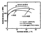
- FIG. 6 is a diagram showing a tensile stress-strain curve of the magnesium alloy of Example 6.
- the horizontal axis of the figure is strain (%), and the vertical axis is tensile stress (MPa).
- Table 4 shows the tensile yield strength, the ultimate tensile yield strength, the elongation, and the thermal conductivity obtained from the stress-strain curve. As shown in FIGS. 6 and 4, the tensile yield strength of the solution-treated material was 181 MPa, the ultimate tensile yield strength was 265 MPa, and the elongation was 28.2%.
- the Eriksen value measured at room temperature was 8.11 mm.
- the tensile yield strength of the aging-treated material subjected to the aging treatment for 4 hours was 227 MPa and the ultimate tensile yield strength was 291 MPa, which were higher than those of the solution-treated material.
- the elongation was 22.6%, which was slightly lower than that of the solution-treated material.
- the tensile yield strength of the aging treated material subjected to the aging treatment for 1000 hours was 171 MPa, the ultimate tensile yield strength was 242 MPa, and the elongation was 23.8%.
- FIG. 7 is a diagram showing the relationship between the tensile yield strength and heat conduction in the aging treatment material subjected to the aging treatment for 4 hours in Example 6 and other commercially available wrought alloys.
- the aging treatment material (T6) subjected to the aging treatment for 4 hours had an excellent balance between the tensile yield strength and the thermal conductivity as compared with other commercially available forged alloys.
- Example 6 is a case where the Zn concentration of Example 3 is increased from 0.8% by mass to 1.6% by mass.
- the thermal conductivity is about 120 W / (m ⁇ K), but this is an example showing that the thermal conductivity exceeding 130 W / (m ⁇ K) can be achieved by the aging treatment.
- the magnesium alloy of the present invention including Example 6, a supersaturated solid solution was formed by quenching the material to be the matrix after the solution treatment, and the solute elements dissolved in the supersaturation by the subsequent aging treatment were dispersed at high density.
- the mechanical strength of the aging treatment material (T6) is increased by precipitating as a fine GP zone precipitate or GP precipitate.
- the amount of solute elements such as Ca, Zn, and Zr that are solid-solved in the magnesium matrix decreases, so that the solute elements contribute to the decrease in thermal conductivity.
- the amount of is reduced.
- the thermal conductivity could be improved as well as the strength. This principle has already been used for aluminum alloys and the like, and it has been found that the present invention can also be applied to magnesium alloys.
- Example 7 (1) Alloy composition: Mg-1.6Zn-0.5Ca-0.4Mn (2) Homogenization treatment: After holding at 300 ° C. for 4 hours, the temperature was raised at 7.5 ° C./h, holding at 450 ° C. for 6 hours, air-cooled to 300 ° C., and then water-cooled. (3) Solution treatment: 1 hour at 400 ° C. (4) Aging treatment: 16 hours at 170 ° C., 500 hours Samples were prepared according to the above experimental procedure, and as shown in Table 1, a homogenization treatment at 300 ° C. was 4 After holding for a time, the temperature was raised at 7.5 ° C./h, further held at 450 ° C.
- Example 7 is an example in which Zr of Example 6 is replaced with Mn.
- Example 8 (1) Alloy composition: Mg-1.6Zn-0.5Ca-0.4Zr-0.3Gd (2) Homogenization treatment: After holding at 300 ° C. for 4 hours, the temperature was raised at 7.5 ° C./h, holding at 450 ° C. for 6 hours, air-cooled to 300 ° C., and then water-cooled. (3) Solution treatment: 400 ° C. for 1 hour (4) Aging treatment: 170 ° C. for 16 hours, 500 hours Samples were prepared according to the above experimental procedure, and as shown in Table 1, at 300 ° C. as a homogenization treatment. After holding for 4 hours, the temperature was raised at 7.5 ° C./h, further held at 450 ° C.
- Example 7 is obtained by adding Gd to the alloy composition of Example 6. Thermal conductivity exceeding 120 W / (m ⁇ K) can be achieved by aging treatment, but in order to achieve thermal conductivity exceeding 130 W / (m ⁇ K), it is better not to add extra elements. I found out.
- Example 9 (1) Alloy composition: Mg-1.6Zn-0.5Ca-0.4Zr (2) Homogenization treatment: After holding at 300 ° C. for 4 hours, the temperature was raised at 7.5 ° C./h, holding at 450 ° C. for 6 hours, air-cooled to 300 ° C., and then water-cooled. (3) Solution treatment: 1 hour at 400 ° C. (4) Aging treatment: 6 hours at 170 ° C., 500 hours Samples were prepared according to the above experimental procedure, and as shown in Table 1, a homogenization treatment at 300 ° C. was 4 After holding for a time, the temperature was raised at 7.5 ° C./h, further held at 450 ° C.
- Example 9 had the same composition as Example 6, but was homogenized without making a plate-shaped sample.
- Example 9 is an example showing that the thermal conductivity is not affected even when a rolling step or the like is not performed to prepare a plate-shaped sample.
- a plate-shaped sample was prepared and solution-treated at 400 ° C. for 2 hours.
- the thermal conductivity of each sample was measured between the solution-treated material, the aging-treated material which was aged at 170 ° C. for 10 hours, and the aging-treated material which was aged for 500 hours.
- the thermal conductivity of each of the above samples was 115.3 W / (m ⁇ K), 116.8 W / (m ⁇ K), and 129.5 W / (m ⁇ K), respectively.
- Comparative Example 1 is an example showing the upper limit of the Zn concentration, and is a case where the amount of Zn added is increased as compared with Example 6. As a result, when 3% by mass of Zn is added, the thermal conductivity can be improved by the aging treatment, but the value higher than 120 W / (m ⁇ K) cannot be obtained by the aging treatment at 170 ° C. for 10 hours.
- Comparative Example 2 (1) Alloy composition: Mg-3.0Al-0.7Zn-0.4Ca-0.3Mn (2) Solution treatment: A sample was prepared according to the above-mentioned experimental procedure at 400 ° C. for 1 hour, and solution treatment was performed at 400 ° C. for 1 hour. The thermal conductivity was measured for the solution-treated material. As a result, the value of thermal conductivity was 85.6 W / (m ⁇ K). Comparative Example 2 is a case where 90% of Zn of Comparative Example 1 is replaced with Al, and when Zn is replaced with Al, the thermal conductivity is remarkably lowered. Therefore, it is shown that Zn is preferable to Al as an alloying element. ing.
- Comparative Example 3 is an example showing the upper limit of the Zn concentration, and the amount of Zn added is increased as compared with Examples and Comparative Example 1.
Landscapes
- Chemical & Material Sciences (AREA)
- Engineering & Computer Science (AREA)
- Materials Engineering (AREA)
- Mechanical Engineering (AREA)
- Metallurgy (AREA)
- Organic Chemistry (AREA)
- Physics & Mathematics (AREA)
- Thermal Sciences (AREA)
- Crystallography & Structural Chemistry (AREA)
- Conductive Materials (AREA)
Abstract
常温を含む温度範囲における大きな熱伝導率と強度を両立させることが可能で、汎用性の高いマグネシウム合金時効処理材を提供するもので、このマグネシウム合金時効処理材は、1質量%以下のCaと3質量%以下のZnとを含有し、残部がMg及び不可避不純物からなり、Mg、Ca及びZnよりなるG.P.ゾーンなどの析出物がマグネシウム母相の(0001)面上に分散しており、前記G.P.ゾーンは、(0001)面において長手方向が4.0から5.0nm以上であり、数密度が1×10²⁰から1×1024m-3の範囲である。
Description
本発明はマグネシウム合金時効処理材とその製造方法に関し、さらに、本発明はマグネシウム合金時効処理材を使用したOA機器、輸送機器及びその部品に関するものである。
マグネシウム合金は実用金属の中で最も軽い金属として知られており、その軽量性を活かすことができる用途として、例えばノートパソコンの筐体や輸送機器の構造材料等が挙げられる。これらの用途には、圧延や押出によって作製した板材や棒材などの展伸材が用いられる。板材をノートパソコンの筐体等として利用する場合は、応用上十分な力学特性に加えて優れた放熱性が要求される。
これまで、市販の展伸マグネシウム合金では主に固溶強化により強化を図ってきた。固溶強化とは、母相とは原子半径が異なる元素を母相に固溶させて格子ひずみを導入することで強化する手法で、溶質元素の量が多ければ多いほど大きな固溶強化量を得ることができる。
しかしながら、一般に熱伝導率が伝導電子の寄与によるところが大きい金属材料では、合金元素を固溶させると熱伝導率が低下する。例えば、特許文献1には、マグネシウムにAl(アルミニウム)と希土類金属を添加し、熱伝導率が80W/(m・K)以上で、200MPa以上の引張強度をもったマグネシウム合金が開示されている。純Mg(マグネシウム)の熱伝導率は、室温で158W/(m・K)であるが、降伏強度は100MPa未満の非常に低いものである(非特許文献1参照)。従って、このようなアプローチからは強度と熱伝導率の両者を同時に向上させることは困難であった。
自動車のエンジンブロックなど、耐熱性が要求されるようなマグネシウム合金の鋳造材では、これまでにMg-Al系の合金に数原子%のCa(カルシウム)を添加して、結晶粒界に沿って熱的に安定な金属間化合物を主に結晶粒界上に形成し、これにより優れた高温強度を得ていた。Caの添加によって粒界上に形成する金属間化合物は、合金元素のAlを含むAl2Caなどの化合物である。Caの添加による金属間化合物の形成は、母相における溶質元素濃度を下げることができるため、熱伝導性の向上にも効果的であった。
マグネシウム合金からなる鋳造合金に対して優れた熱伝導性とクリープ特性を付与するための方法に共通しているのは、合金元素を晶出物として粒内もしくは粒界に沿って晶出させている点である。合金元素が晶出物を形成すると、母相における合金元素の濃度が低下するため、優れた熱伝導性を付与することが可能となる。晶出物を粒界上に形成することで3次元の網目状ネットワーク(特許文献2参照)を形成すると、強度メンバーとして利用することができるという利点もあるが、延性が著しく損なわれるおそれがある。さらに、加工性と強度を両立させることが可能なマグネシウム合金が開示されている(特許文献3、非特許文献3及び4参照)。
X. Tong, G.Q. You, Y.H. Ding,H.S. Xue, Y.C. Wang, W. Guo,Mater. Lett. 229 (2018) 261-264
X. Gao, B.C. Muddle, J.F. Nie, Philos. Mag. Lett. 89 (2009) 33 - 43
Bian et al., Magnesium Technology 2018, 361-364
B.C. Suh et al., MagnesiumTechnology 2018, 373-377
しかしながら、Ca添加により形成する金属間化合物は非常に粗大であることから、こうした合金に展伸加工を行って板材や棒材を作製しても良好な延性が得られない。そのため、展伸加工後に最終形状への加工が必要とされるような板材として好ましくはない。
先行技術では、市販の展伸材や、最近報告された鋳造材の強化手法が力学特性と熱伝導性の両者を向上させることが困難な点が課題である。従来の展伸マグネシウム合金の強化手法として固溶強化が用いられてきた。しかし、一般的に熱伝導率が伝導電子の寄与によるところが大きい金属材料では、合金元素を固溶させると熱伝導率が低下する。そのため、固溶強化によって強度と熱伝導率の両方を同時に向上させることは困難である。
Mg-Al系の鋳造合金に数原子%のCaを添加して、結晶粒界に沿って熱的に安定な金属間化合物を形成することによって優れた高温強度を得た例がある。しかしながら、Ca添加により形成する金属間化合物は非常に粗大であることから、このようにして得た合金に展伸加工を行って板材や棒材を作製しても、良好な延性や成形性が得られない。よって展伸加工後に最終形状への加工が必要とされるような板材としては好ましくない。
ところで、OA機器の筐体やパネル材は、機械的性質と共に放熱のために熱伝導率が大凡120W/(m・K)以上を有する合金が求められている。多くの用途において、強度と常温での優れた熱伝導率の両方を発現する合金が強く求められている。ところが従来のマグネシウム合金の製造方法では、強度と常温における熱伝導率とを十分に兼ね備えた汎用性の高いマグネシウム合金は得られなかった。
本発明は、常温を含む温度範囲において大きな熱伝導率と強度を両立させることが可能で、汎用性の高いマグネシウム合金時効処理材を提供することを第1の目的とし、マグネシウム合金時効処理材の製造方法を提供することを第2の目的とする。さらに、マグネシウム合金時効処理材を使用したOA機器を提供することを第3の目的とし、マグネシウム合金時効処理材を使用した輸送機器を提供することを第4の目的とする。
本発明者等は、従来のマグネシウム合金の固溶強化に代えて、新たに時効処理によりマグネシウム母相からG.P.ゾーンを高密度に析出させる析出強化によってマグネシウム合金を強化することで、大きな熱伝導性と機械的強度の向上が実現できるという知見を得て本発明に想到したものである。
上記第1の目的を達成するため、本発明のマグネシウム合金時効処理材は、1質量%以下のCaと、3質量%以下のZnと、を含有し、残部がMg及び不可避不純物からなり、Mg、Ca及びZnよりなるG.P.ゾーンがマグネシウム母相の(0001)面上に分散しており、前記G.P.ゾーンは、(0001)面において長手方向が4.0乃至5.0nm以上であり、数密度が1×10²⁰から1×1024m-3の範囲である。
上記マグネシウム合金時効処理材は、好ましくは、0.5質量%以上1質量%以下のCaと0.8質量%以上3質量%以下のZnとを含有し、残部がMg及び不可避不純物からなる。前記マグネシウム合金時効処理材の熱伝導率は、好ましくは、120W/(m・K)以上である。このマグネシウム合金時効処理材は、さらにジルコニウム又はマンガンを含んでもよく、ガドリニウム又はセリウムを含んでもよい。
上記第2の目的を達成するため、本発明のマグネシウム合金時効処理材の製造方法は、
Mg、Zn及びCaを溶解して鋳造固体を得る工程と、
前記鋳造固体を均質化処理して均質化処理材を得る工程と、
前記均質化処理材を時効処理してマグネシウム合金時効処理材を得る工程と、
を含み、
前記マグネシウム合金時効処理材の組成が、1質量%以下のCaと、3質量%以下のZnと、を含有し、残部がMg及び不可避不純物からなる。
Mg、Zn及びCaを溶解して鋳造固体を得る工程と、
前記鋳造固体を均質化処理して均質化処理材を得る工程と、
前記均質化処理材を時効処理してマグネシウム合金時効処理材を得る工程と、
を含み、
前記マグネシウム合金時効処理材の組成が、1質量%以下のCaと、3質量%以下のZnと、を含有し、残部がMg及び不可避不純物からなる。
上記時効処理を、好ましくは、140℃から250℃の温度範囲でマグネシウム合金時効処理材の熱伝導率が120W/(m・K)以上になるまで行う。
均質化処理材を得る工程とマグネシウム合金時効処理材を得る工程との間において、好ましくは、均質化処理材を溶体化処理して溶体化処理材を得る工程を挿入する。
均質化処理材を得る工程と溶体化処理材を得る工程との間において、好ましくは、均質化処理材を展伸加工する工程を挿入する。均質化処理は、好ましくは300℃以上500℃以下で所定時間行う。
均質化処理材を得る工程とマグネシウム合金時効処理材を得る工程との間において、好ましくは、均質化処理材を溶体化処理して溶体化処理材を得る工程を挿入する。
均質化処理材を得る工程と溶体化処理材を得る工程との間において、好ましくは、均質化処理材を展伸加工する工程を挿入する。均質化処理は、好ましくは300℃以上500℃以下で所定時間行う。
上記第3の目的を達成する本発明のOA機器は、前記のマグネシウム合金時効処理材を使用した筐体又はパネル材を有する。
上記第4の目的を達成する本発明の輸送機器及びその部品は、前記のマグネシウム合金時効処理材を使用しているか又はその部品として用いる。
本発明は、常温を含む温度範囲において高い強度と熱伝導率を両立させることが可能で、汎用性の高いマグネシウム合金時効処理材及びその製造方法、並びにそれを使用したOA機器、輸送機器及びその部品を提供することができる。
以下、本発明の実施形態について詳細に説明する。
本発明のマグネシウム合金時効処理材は、1質量%以下のCa(カルシウム)と3質量%以下のZn(亜鉛)とを含有し、残部がMg(マグネシウム)及び不可避不純物からなる合金である。ここで、1質量%以下のCaとは、0質量%よりも多く1質量%以下のCaである。3質量%以下のCaとは、0質量%よりも多く3質量%以下のZnである。さらに好ましくは、0.5質量%以上1質量%以下のCaと0.8質量%以上3質量%以下のZnとを含有し、残部がMg及び不可避不純物からなる合金である。
本発明のマグネシウム合金時効処理材は、第2相としてMg、Ca及びZnよりなるGuinier Preston ゾーン(以下G.P.ゾーンという)がマグネシウム母相の(0001)面上に分散して析出している。G.P.ゾーンは、寸法が4.0から5.0nm以上で、数密度が1×10²⁰から1×1024m-3の範囲である。ここで、G.P.ゾーンの数密度は、マグネシウム合金の1m3当たりに存在するG.P.ゾーンの数と定義される。G.P.ゾーンの数密度は、後述するアトムプローブ(3DAP)を用いた3DAP分析により測定することができる。マグネシウム合金時効処理材の熱伝導率は、120W/(m・K)以上であり、さらに、成分元素としてZr(ジルコニウム)又はMn(マンガン)を含んでもよい。さらに、Gd(ガドリニウム)又はCe(セリウム)を含んでもよい。以下、合金の組成等について詳細に説明する。
(添加する元素量の上限)
優れた熱伝導性を得るにはMgに添加する合金元素の濃度が低ければ低いほど良いので、合金元素濃度の下限値はなく、上限値を設定すればよい。Caの上限の値としては1質量%以下が好ましい。Caを1質量%以上添加すると、溶体化処理後の水焼き入れ、つまり急冷中に試料が割れる可能性があることが経験的に分かっているため好ましくない。
優れた熱伝導性を得るにはMgに添加する合金元素の濃度が低ければ低いほど良いので、合金元素濃度の下限値はなく、上限値を設定すればよい。Caの上限の値としては1質量%以下が好ましい。Caを1質量%以上添加すると、溶体化処理後の水焼き入れ、つまり急冷中に試料が割れる可能性があることが経験的に分かっているため好ましくない。
優れた熱伝導性を得るにはMgに添加するZnの濃度が低いほど良いので、Znの濃度下限値はなく、上限値を設定すればよい。Znの濃度としては、0質量%よりも多く3質量%以下がこの好ましい。Znの濃度の上限値としては、後述する比較例1から、120W/(m・K)の熱伝導率を得るためには、3質量%未満にすることが好ましい。
(添加する元素量の下限)
より好ましい実施形態である130W/(m・K)以上の熱伝導率をMg-Zn-Ca系合金で得るには、時効処理が必要となる。時効処理によって第2相を析出させるには、後述する実施例1と実施例2、3の比較から、0質量%よりも多く、例えば、0.5質量%以上のCaの添加が必要となる。また、実施例2に記載の通り、Zn濃度は0.8質量%以上添加することが望ましい。この観点からは、本発明のマグネシウム合金時効処理材は、0.5質量%以上1質量%以下のCaと0.8質量%以上3質量%以下のZnとを含有し、残部がMg及び不可避不純物からなる合金であることが望ましい。
より好ましい実施形態である130W/(m・K)以上の熱伝導率をMg-Zn-Ca系合金で得るには、時効処理が必要となる。時効処理によって第2相を析出させるには、後述する実施例1と実施例2、3の比較から、0質量%よりも多く、例えば、0.5質量%以上のCaの添加が必要となる。また、実施例2に記載の通り、Zn濃度は0.8質量%以上添加することが望ましい。この観点からは、本発明のマグネシウム合金時効処理材は、0.5質量%以上1質量%以下のCaと0.8質量%以上3質量%以下のZnとを含有し、残部がMg及び不可避不純物からなる合金であることが望ましい。
(その他の合金元素の添加について)
さらに結晶粒微細化による強度増加を可能にするために、添加する結晶粒微細化剤として、Zr又はMnを添加してもよい。後述する実施例3と5、又は実施例6と7の比較から、Zr又はMnを結晶粒微細化剤として添加することが望ましい。さらに、好ましくは結晶粒微細化剤としてZrを添加する。
さらに結晶粒微細化による強度増加を可能にするために、添加する結晶粒微細化剤として、Zr又はMnを添加してもよい。後述する実施例3と5、又は実施例6と7の比較から、Zr又はMnを結晶粒微細化剤として添加することが望ましい。さらに、好ましくは結晶粒微細化剤としてZrを添加する。
時効硬化性の向上や圧延時の集合組織制御のための添加元素として、CeやGdを加えることが好ましい。後述する実施例5、8に示すように、合金元素の添加により熱伝導性は低下するので、添加量は必要最小限に抑えることが好ましい。マグネシウム合金を一般式Mg-Ca-X(XはZn又はAl)合金と表記した場合、後述する比較例1、2と実施例6の比較から、X元素としてはAlよりもZnの添加が適切である。
次に、マグネシウム合金時効処理材の製造方法について説明する。
図1は、本発明のマグネシウム合金時効処理材の製造方法を示すフロー図である。本発明のマグネシウム合金の製造方法は、Mg、Zn、Ca等の原料を溶解した後鋳造して鋳造固体を得る工程1と、鋳造固体を均質化処理して均質化処理材(T4処理とも呼ぶ)を得る工程2と、必要により、均質化処理材を展伸加工して加工材を得る工程3と、加工材を溶体化処理して溶体化処理材を得る工程4と、溶体化処理材を時効処理してマグネシウム合金時効処理材(T6処理とも呼ぶ)を得る工程5と、を含んでいる。
図1は、本発明のマグネシウム合金時効処理材の製造方法を示すフロー図である。本発明のマグネシウム合金の製造方法は、Mg、Zn、Ca等の原料を溶解した後鋳造して鋳造固体を得る工程1と、鋳造固体を均質化処理して均質化処理材(T4処理とも呼ぶ)を得る工程2と、必要により、均質化処理材を展伸加工して加工材を得る工程3と、加工材を溶体化処理して溶体化処理材を得る工程4と、溶体化処理材を時効処理してマグネシウム合金時効処理材(T6処理とも呼ぶ)を得る工程5と、を含んでいる。
(工程1:鋳造)
工程1では、0質量%よりも多く1質量%以下のCaと0質量%よりも多く3質量%以下のZnとを含有し、残部がMg及び不可避不純物からなる合金成分を溶解した後で鋳造固体を作製する。工程1においては、必要に応じてマグネシウム合金にさらにZr等を添加してもよい。溶解の際に用いる手法は、如何なる方法であっても、所望の組成の合金が作製できればよい。例えば、合金成分の溶解は、高周波誘導溶解炉を用いてアルゴン雰囲気下で所望の組成の合金を溶解し、鉄などからなる鋳型に流し込み、冷却することにより鋳造できる。溶解の際に用いる溶解炉や鋳造固体の寸法は特に限定はされるものではなく、所望の組成の鋳造固体が作製できればよい。
工程1では、0質量%よりも多く1質量%以下のCaと0質量%よりも多く3質量%以下のZnとを含有し、残部がMg及び不可避不純物からなる合金成分を溶解した後で鋳造固体を作製する。工程1においては、必要に応じてマグネシウム合金にさらにZr等を添加してもよい。溶解の際に用いる手法は、如何なる方法であっても、所望の組成の合金が作製できればよい。例えば、合金成分の溶解は、高周波誘導溶解炉を用いてアルゴン雰囲気下で所望の組成の合金を溶解し、鉄などからなる鋳型に流し込み、冷却することにより鋳造できる。溶解の際に用いる溶解炉や鋳造固体の寸法は特に限定はされるものではなく、所望の組成の鋳造固体が作製できればよい。
(工程2:均質化処理)
工程2では、均質化処理として、鋳造合金中に存在する合金元素の偏析や溶湯の冷却中に形成する化合物を母相に固溶させ、合金元素分布を均質化するために熱処理を行う。鋳造固体を300℃以上500℃以下、さらに好ましくは350℃以上450℃以下の範囲で所定時間の均質化処理を行うことで均質化固体を作製する。条件の詳細は後述する表1に記載した。合金元素が高濃度にマクロ偏析した領域では、高温での熱処理を行うと融解するため、所定の温度での熱処理の前に、低温での熱処理を行ってもよい。例えば、Znが高濃度にマクロ偏析している領域では、450℃で熱処理を開始すると合金が局所的に融解する、つまり、初期溶融するおそれがある。そのため、最初に300℃から350℃の範囲で熱処理することで、鋳造時に形成されたMg-Zn相の初期溶融を抑制してZnを分散した後、400℃以上500℃以下において所定時間の熱処理を施すことで、Znの分布を均質化して均質化固体を得てもよい。
工程2では、均質化処理として、鋳造合金中に存在する合金元素の偏析や溶湯の冷却中に形成する化合物を母相に固溶させ、合金元素分布を均質化するために熱処理を行う。鋳造固体を300℃以上500℃以下、さらに好ましくは350℃以上450℃以下の範囲で所定時間の均質化処理を行うことで均質化固体を作製する。条件の詳細は後述する表1に記載した。合金元素が高濃度にマクロ偏析した領域では、高温での熱処理を行うと融解するため、所定の温度での熱処理の前に、低温での熱処理を行ってもよい。例えば、Znが高濃度にマクロ偏析している領域では、450℃で熱処理を開始すると合金が局所的に融解する、つまり、初期溶融するおそれがある。そのため、最初に300℃から350℃の範囲で熱処理することで、鋳造時に形成されたMg-Zn相の初期溶融を抑制してZnを分散した後、400℃以上500℃以下において所定時間の熱処理を施すことで、Znの分布を均質化して均質化固体を得てもよい。
(工程3:展伸加工)
工程3では、必要に応じて均質化処理工程2と溶体化処理工程4との間に挿入される工程であり、例えば圧延、押出によって鋳造材を展伸加工し、板材や棒材のような加工材に加工する。この工程3は熱伝導性を向上させるために必ずしも必要な工程ではない。例えば、均質化固体を熱間又は温間における圧延等により板材に加工することで、板状の加工材を作製する。展伸加工による板材の作製は、熱間加工または温間加工、特に圧延加工に限定されず、微細組織が作製できる展伸加工法であれば他の加工方法でもよい。
工程3では、必要に応じて均質化処理工程2と溶体化処理工程4との間に挿入される工程であり、例えば圧延、押出によって鋳造材を展伸加工し、板材や棒材のような加工材に加工する。この工程3は熱伝導性を向上させるために必ずしも必要な工程ではない。例えば、均質化固体を熱間又は温間における圧延等により板材に加工することで、板状の加工材を作製する。展伸加工による板材の作製は、熱間加工または温間加工、特に圧延加工に限定されず、微細組織が作製できる展伸加工法であれば他の加工方法でもよい。
(工程4:溶体化処理)
工程4では、圧延等で得た板状の有形固体を溶体化処理し、これを冷却することで溶体化処理材を作製する。圧延加工中に形成した微細析出物をマグネシウム母相に固溶させ、かつ再結晶した組織を形成させるために実施する。圧延加工を行わない場合は、工程2の均質化処理と併せて行い、溶体化処理は省略してもよい。この場合には、均質化処理材を得る工程2の次に均質化処理材を時効処理してマグネシウム合金時効処理材を得る工程5を行う。溶体化処理では、加工材を熱処理することで、熱間または温間加工中に形成された微細析出物をマトリックス中に固溶させ、かつ再結晶させて組織を形成する。350℃以上500℃以下の範囲で15分から24時間の溶体化処理を行う。ただし、熱処理時間の長時間化は製造コストの増加につながるので必要以上の時間を行う必要はない。種々の温度条件にて行うことができ、条件の詳細は後述する表1に記載した。熱間または温間加工後に溶体化処理を施すことで、結晶粒の配向をランダムに配向させることができ、優れた成形性を付与することができる。
工程4では、圧延等で得た板状の有形固体を溶体化処理し、これを冷却することで溶体化処理材を作製する。圧延加工中に形成した微細析出物をマグネシウム母相に固溶させ、かつ再結晶した組織を形成させるために実施する。圧延加工を行わない場合は、工程2の均質化処理と併せて行い、溶体化処理は省略してもよい。この場合には、均質化処理材を得る工程2の次に均質化処理材を時効処理してマグネシウム合金時効処理材を得る工程5を行う。溶体化処理では、加工材を熱処理することで、熱間または温間加工中に形成された微細析出物をマトリックス中に固溶させ、かつ再結晶させて組織を形成する。350℃以上500℃以下の範囲で15分から24時間の溶体化処理を行う。ただし、熱処理時間の長時間化は製造コストの増加につながるので必要以上の時間を行う必要はない。種々の温度条件にて行うことができ、条件の詳細は後述する表1に記載した。熱間または温間加工後に溶体化処理を施すことで、結晶粒の配向をランダムに配向させることができ、優れた成形性を付与することができる。
(工程5:時効処理)
工程5では、溶体化処理材を熱処理により時効処理することで、溶体化処理された加工材に析出させた析出物を分散させて強度を付与し、これにより本発明のマグネシウム合金時効処理材を作製する。本発明では、商用マグネシウム合金では従来使われなかった時効処理を用いることで、マグネシウム合金の大幅な強化と大きな熱伝導率を達成することができる。時効処理では、140℃から250℃の温度範囲で所定時間の時効処理を行う。時効処理を行う時間はマグネシウム合金の熱伝導率が増大する時間、好ましくはマグネシウム合金の熱伝導率が120W/(m・K)以上又は最大となる時間行う。例えば、油浴中にて170℃で時効処理を行う。
工程5では、溶体化処理材を熱処理により時効処理することで、溶体化処理された加工材に析出させた析出物を分散させて強度を付与し、これにより本発明のマグネシウム合金時効処理材を作製する。本発明では、商用マグネシウム合金では従来使われなかった時効処理を用いることで、マグネシウム合金の大幅な強化と大きな熱伝導率を達成することができる。時効処理では、140℃から250℃の温度範囲で所定時間の時効処理を行う。時効処理を行う時間はマグネシウム合金の熱伝導率が増大する時間、好ましくはマグネシウム合金の熱伝導率が120W/(m・K)以上又は最大となる時間行う。例えば、油浴中にて170℃で時効処理を行う。
このようにして製造される本発明のマグネシウム合金時効処理材は、0質量%よりも多く1質量%以下のCaと0質量%よりも多く3質量%以下のZnとを含有し、残部がMg及び不可避不純物からなり、Mg、Ca及びZnからなるナノメートルオーダーの析出物(G.P.ゾーン)がマグネシウム母相の(0001)面上に分散している合金である。
本発明によれば、MgにCa及びZnを添加し、時効処理を行うことによりG.P.ゾーンと呼ばれるマグネシウム母相と整合する界面を有するナノ析出物を高密度に形成することができる。これにより延性を著しく損なうことなく、熱伝導性、機械的強度を向上させることができる時効処理材を提供することができる。
本発明のマグネシウム合金時効処理材は、溶体化処理と、時効処理という低温の熱処理との組み合わせによって、整合するナノスケール析出物をマグネシウム母相に整合するナノスケール析出物であるG.P.ゾーンとして高密度に分散させることができる。これにより、高価な元素を使用せずに、優れた熱伝導性と力学特性を両立させたマグネシウム合金時効処理材を低コストで製造することができる。
(OA機器)
オフィスオートメーション機器(Office Automation、OA機器と呼ぶ)は、本発明のマグネシウム合金時効処理材を使用した筐体やパネル材を有している。OA機器は、会社や事務所等のオフィスオートメーションに必要な機器の総称であり、特に制限なく目的に応じたOA機器に適用することができる。例えば、コンピュータとしてノートパソコンやデスクトップパソコン、携帯電話(スマートフォン)、携帯情報端末(Personal Digital Assistant、PDAとも呼ぶ)、コピー機、各種プリンター、ファクシミリ(FAX)等が挙げられる。
オフィスオートメーション機器(Office Automation、OA機器と呼ぶ)は、本発明のマグネシウム合金時効処理材を使用した筐体やパネル材を有している。OA機器は、会社や事務所等のオフィスオートメーションに必要な機器の総称であり、特に制限なく目的に応じたOA機器に適用することができる。例えば、コンピュータとしてノートパソコンやデスクトップパソコン、携帯電話(スマートフォン)、携帯情報端末(Personal Digital Assistant、PDAとも呼ぶ)、コピー機、各種プリンター、ファクシミリ(FAX)等が挙げられる。
OA機器において、本発明のマグネシウム合金時効処理材の展伸加工により加工した筐体やパネル材は、例えば、OA機器の筐体やパネル材として使用される。
(輸送機器及びその部品)
輸送機器及びその部品に対して本発明のマグネシウム合金時効処理材によるパネル材を使用してもよい。輸送機器としては、自動車、航空機、ドローンのような飛翔体、鉄道用車両等が挙げられ、特に制限はなく目的に応じて適宜適用することができる。
輸送機器及びその部品に対して本発明のマグネシウム合金時効処理材によるパネル材を使用してもよい。輸送機器としては、自動車、航空機、ドローンのような飛翔体、鉄道用車両等が挙げられ、特に制限はなく目的に応じて適宜適用することができる。
輸送機器の部品としては、本発明のマグネシウム合金時効処理材を用いた部品である。さらに、圧延等の展伸加工により加工したパネル材等は、例えば、自動車のパネル材や後部座席の部品として用いるラゲージリテイナー等の部品である。
本発明の実施例をさらに詳細に説明する。
実施例及び比較例の各試料の測定は以下の方法で実施した。
(熱伝導率の測定)
縦×横が10×10mmで、厚さが1mmの試料を作製し、レーザーフラッシュ法を用いて測定を行った。熱伝導率λ(W/(m・K)は、式(a×Cp×ρ)から計算した。ここで、熱拡散率a(m2/s)は、298Kで熱伝導測定装置(Linseis LFA 1000レーザーフラッシュアナライザー)により測定した。室温の密度ρ(g/cm3)は、アルキメデス法(Mettler社製、 Toledo AG285)により測定した。比熱容量Cp(J/g・K)は、ノイマン・コップの法則によって推定した。
実施例及び比較例の各試料の測定は以下の方法で実施した。
(熱伝導率の測定)
縦×横が10×10mmで、厚さが1mmの試料を作製し、レーザーフラッシュ法を用いて測定を行った。熱伝導率λ(W/(m・K)は、式(a×Cp×ρ)から計算した。ここで、熱拡散率a(m2/s)は、298Kで熱伝導測定装置(Linseis LFA 1000レーザーフラッシュアナライザー)により測定した。室温の密度ρ(g/cm3)は、アルキメデス法(Mettler社製、 Toledo AG285)により測定した。比熱容量Cp(J/g・K)は、ノイマン・コップの法則によって推定した。
(透過型電子顕微鏡像)
微細構造の特性評価としての透過型電子顕微鏡像は、透過型電子顕微鏡(FEI Tecnai 20及びTitanG280-200)を使用して取得した。TEM又はSTEMの観察用の薄いフォイル試験片は、直径3mmのディスクを打ち抜き、90Vの電圧で約-50℃でツインジェット電解研磨することにより作製した。
微細構造の特性評価としての透過型電子顕微鏡像は、透過型電子顕微鏡(FEI Tecnai 20及びTitanG280-200)を使用して取得した。TEM又はSTEMの観察用の薄いフォイル試験片は、直径3mmのディスクを打ち抜き、90Vの電圧で約-50℃でツインジェット電解研磨することにより作製した。
(3DAP分析)
3次元アトムプローブ(3 dimensional atom Probe, 3DAPとも呼ぶ)は、針状試料に高電圧を印加し、試料の表面から電界蒸発するイオンを質量分析装置で検出して、個々に検出されたイオンを深さ方向へ連続的に検出し、検出された順番にイオンを並べることにより、3次元の原子分布を測定する方法である。3DAP分析は、ローカル電極アトムプローブ(CAMECA社製、LEAP5000XS)を使用し、30Kの温度で、電圧パルスモードで行った。3DAP分析用の電界蒸発に用いる鋭い針状の試料は、SEM・集束イオンビーム装置(FIB、FEIHeliosG4UX)を用いたリフトアウト及びアニュラーミリング技術によって作製した。G.P.ゾーンの数密度は、3DAP分析に用いた質量分析装置(CAMECA社製)のデータ解析ソフトにより測定した。最初に、測定した試料のデータから試料の体積を算出する。データ解析ソフトとしては、CAMECA社製IVASを用いた。次に、データの等濃度面を用いて試料のG.P.ゾーンの位置を検出して、G.P.ゾーンの数を計数し、このG.P.ゾーンの数を最初に取得した体積で除してG.P.ゾーンの数密度を計算した。
3次元アトムプローブ(3 dimensional atom Probe, 3DAPとも呼ぶ)は、針状試料に高電圧を印加し、試料の表面から電界蒸発するイオンを質量分析装置で検出して、個々に検出されたイオンを深さ方向へ連続的に検出し、検出された順番にイオンを並べることにより、3次元の原子分布を測定する方法である。3DAP分析は、ローカル電極アトムプローブ(CAMECA社製、LEAP5000XS)を使用し、30Kの温度で、電圧パルスモードで行った。3DAP分析用の電界蒸発に用いる鋭い針状の試料は、SEM・集束イオンビーム装置(FIB、FEIHeliosG4UX)を用いたリフトアウト及びアニュラーミリング技術によって作製した。G.P.ゾーンの数密度は、3DAP分析に用いた質量分析装置(CAMECA社製)のデータ解析ソフトにより測定した。最初に、測定した試料のデータから試料の体積を算出する。データ解析ソフトとしては、CAMECA社製IVASを用いた。次に、データの等濃度面を用いて試料のG.P.ゾーンの位置を検出して、G.P.ゾーンの数を計数し、このG.P.ゾーンの数を最初に取得した体積で除してG.P.ゾーンの数密度を計算した。
(時効硬化応答)
時効硬化応答は、300gの荷重下でマイクロビッカース硬さ試験機(ミツトヨ社製、HM-101)によって測定した。
時効硬化応答は、300gの荷重下でマイクロビッカース硬さ試験機(ミツトヨ社製、HM-101)によって測定した。
(引張特性)
引張特性は、10-3s-1の初期ひずみ速度で引張試験機(インストロン、5567)を用いて室温で評価した。ゲージ長が12.5mm、幅が5mmの引張試験片を、溶質処理材及び時効処理材から機械加工することで作製した。
引張特性は、10-3s-1の初期ひずみ速度で引張試験機(インストロン、5567)を用いて室温で評価した。ゲージ長が12.5mm、幅が5mmの引張試験片を、溶質処理材及び時効処理材から機械加工することで作製した。
(エリクセン値)
常温での加工性を評価するエリクセン値(I.E.値)は、エリクセン試験により外周部を固定した薄板に球頭パンチを一定のスピードで押し当てることで薄板を変形させて、材料に破断が生じるまでのくぼみの高さにより測定した。エリクセン値を試験器(エリクセン社製、111型)により評価した。
常温での加工性を評価するエリクセン値(I.E.値)は、エリクセン試験により外周部を固定した薄板に球頭パンチを一定のスピードで押し当てることで薄板を変形させて、材料に破断が生じるまでのくぼみの高さにより測定した。エリクセン値を試験器(エリクセン社製、111型)により評価した。
(実施例1)
(1)合金組成 :Mg-1.0Zn-0.3Ca-0.3Zr
(2)均質化処理 :300℃で4時間保持後、7.5℃/hで昇温し、450℃で6時間保持後、水冷した。
(3)溶体化処理:450℃で2時間
(4)時効処理:170℃で6時間、500時間
上述の実験手順に従って試料を作製し、表1に記載の通り、均質化処理として300℃で4時間保持後に7.5℃/h(hは1時間である)で昇温し、さらに450℃で6時間保持した後、水冷した。
(1)合金組成 :Mg-1.0Zn-0.3Ca-0.3Zr
(2)均質化処理 :300℃で4時間保持後、7.5℃/hで昇温し、450℃で6時間保持後、水冷した。
(3)溶体化処理:450℃で2時間
(4)時効処理:170℃で6時間、500時間
上述の実験手順に従って試料を作製し、表1に記載の通り、均質化処理として300℃で4時間保持後に7.5℃/h(hは1時間である)で昇温し、さらに450℃で6時間保持した後、水冷した。

その後、板状試料を作製し、450℃で2時間の条件で溶体化処理を行った。溶体化処理材と、溶体化処理材に対して170℃で6時間の時効処理した時効処理材と、500時間の時効処理を行って得た時効処理材の、各試料の熱伝導率の測定を行った。表2に詳細な時効条件及び熱伝導率を纏めて示す。

上記各試料の熱伝導率は上記の方法で測定したが、それぞれ125.2W/(m・K)、127.7W/(m・K)、134.8W/(m・K)で、時効処理による若干の熱伝導率の上昇がみられた。
(実施例2)
(1)合金組成:Mg-0.8Zn-0.5Ca-0.4Zr
(2)均質化処理:300℃で4時間保持後、7.5℃/hで昇温し、450℃で6時間保持後、水冷した。
(3)溶体化処理:450℃で1時間
(4)時効処理:170℃で10時間、500時間
上述の実験手順に従って試料を作製し、表1に記載の通り均質化処理として300℃で4時間保持後に7.5℃/hで昇温し、さらに450℃で6時間保持した後、水冷した。その後、板状試料を作製し、450℃で1時間の条件で溶体化処理を行った。
溶体化処理材と、溶体化処理材に対して170℃で10時間の時効処理した時効処理材と、500時間の時効処理を行った時効処理材の、各試料の熱伝導率を測定した。その結果、上記各試料の熱伝導率は、それぞれ123.8W/(m・K)、130.9W/(m・K)、135.1W/(m・K)で、時効処理によって熱伝導率の上昇がみられた。実施例2では、実施例1よりもCaの添加量を増加した。時効処理で熱伝導率を上げるには0.5%程度のCa添加が必要であることが判明した。
(実施例3)
(1)合金組成:Mg-0.8Zn-0.8Ca-0.4Zr
(2)均質化処理:300℃で4時間保持後、7.5℃/hで昇温し、450℃で6時間保持後、水冷した。
(3)溶体化処理:450℃で1時間
(4)時効処理:170℃で16時間、500時間
上述の実験手順に従って試料を作製し、表1に記載の通り均質化処理として300℃で4時間保持後に7.5℃/hで昇温し、さらに450℃で6時間保持した後、水冷した。その後、板状試料を作製し、450℃で1時間の条件で溶体化処理を行った。
溶体化処理材と、溶体化処理材に対して170℃で16時間の時効処理した時効処理材と、500時間の時効処理した時効処理材の、各試料の熱伝導率を測定した。その結果、上記各試料の熱伝導率は、それぞれ126.8W/(m・K)、130.7W/(m・K)、130.2W/(m・K)で、時効処理により熱伝導率が上昇した。実施例3では、実施例2よりもさらにCaの添加量を増加したが、熱伝導率は実施例2よりも低下した。これにより、時効処理で熱伝導率を上げるには0.5%程度のCa添加が必要であることが分かった。
(実施例4)
(1)合金組成:Mg-0.8Zn-0.8Ca-0.3Mn
(2)均質化処理:300℃で4時間保持後、7.5℃/hで昇温し、450℃で6時間保持後、水冷した。
(3)溶体化処理:450℃で1時間
(4)時効処理:170℃で16時間、500時間
上述の実験手順に従って試料を作製し、表1に記載の通り均質化処理として300℃で4時間保持後に7.5℃/hで昇温し、さらに450℃で6時間保持した後、水冷した。その後、板状試料を作製し、450℃で1時間の条件で溶体化処理を行った。
溶体化処理材と、溶体化処理材に対して170℃で16時間の時効処理した時効処理材と、500時間の時効処理した時効処理材の、各試料の熱伝導率を測定した。その結果、上記各試料の熱伝導率は、それぞれ121.0W/(m・K)、129.5W/(m・K)、129.5W/(m・K)で、時効処理によって熱伝導率の上昇がみられた。実施例4は、実施例3のZrをMnに置換した合金組成とした。Mnに代えても120W/(m・K)を超える熱伝導率を達成できたが、熱伝導率は実施例3よりも低下した。これにより、130W/(m・K)を超える熱伝導率を達成するには、MnよりもZrを微細化剤として添加することが好ましいことが分かった。
(実施例5)
(1)合金組成:Mg-1.6Zn-0.5Ca-0.5Mn-0.2Ce
(2)均質化処理:300℃で4時間保持後、7.5℃/hで昇温し、450℃で6時間保持後、水冷した。
(3)溶体化処理:450℃で1時間
(4)時効処理:170℃で4時間、500時間
上述の実験手順に従って試料を作製し、表1に記載の通り均質化処理として300℃で4時間保持後に7.5℃/hで昇温し、さらに450℃で6時間保持した後、水冷した。その後、板状試料を作製し、450℃で1時間の条件で溶体化処理を行った。
溶体化処理材と、溶体化処理材に対して170℃で4時間の時効処理した時効処理材と、500時間の時効処理した時効処理材との各試料の熱伝導率を測定した。その結果、上記各試料の熱伝導率は、それぞれ113.2W/(m・K)、115.9W/(m・K)、121.1 W/(m・K)であった。実施例5の合金組成は実施例4にCeを添加したものである。120W/(m・K)を超える熱伝導率を達成できるが、熱伝導率は実施例4よりも低下した。これにより、130W/(m・K)を超える熱伝導率を達成するには、実施例3又は4の組成で良く、余分な元素を加えない方が良いことが分かった。
(実施例6)
(1)合金組成:Mg-1.6Zn-0.5Ca-0.4Zr
(2)均質化処理:300℃で4時間保持後、7.5℃/hで昇温し、450℃で6時間保持、300℃まで空冷後に水冷した。
(3)溶体化処理:450℃で1時間
(4)時効処理:170℃で6時間、500時間
上述の実験手順に従って試料を作製し、表1の通り均質化処理として300℃で4時間保持後に7.5℃/hで昇温し、さらに450℃で6時間保持し、300℃まで空冷後に水冷した。その後、板状試料を作製し、450℃で2時間の条件で溶体化処理を行った。
溶体化処理材と、溶体化処理材に対して170℃で6時間の時効処理した時効処理材と、500時間の時効処理した時効処理材との、各試料の熱伝導率を測定した。その結果、上記各試料の熱伝導率は、それぞれ122.6W/(m・K)、128.3W/(m・K)、135.8W/(m・K)で、時効処理によって熱伝導率の上昇がみられた。
図2は、実施例6におけるマグネシウム合金の明視野透過電子顕微鏡像で、(a)は溶体化処理材、(b)は170℃で4時間の時効処理した時効処理材、(c)は170℃で120時間の時効処理した時効処理材、(d)は170℃で1000時間の時効処理を施した時効処理材を示している。各明視野透過電子顕微鏡像は、[112バー0]のゾーン軸から撮影したものである。また、下側に示す像は、対応する選択領域電子線回折パターン(Selected Area Electron Diffraction:SAEDパターンと呼ぶ)であり、[101バー0]α及び[0001]α方向から撮影したものである。図2(a)に示すように、溶体化処理材は、粒界と粒内部に沿って棒状の塊状の粒子を含んでおり、該粒子が溶体化処理中の再結晶粒の成長を抑制したことを示唆している。Gao等によると、該粒子はZn2Zr3相と推定される(非特許文献2参照)。
図2(b)に示すように、4時間の時効処理材の場合、SAEDパターンのコントラストは、Mgマトリクスの底面にnmスケールの板状析出物が密に分布している。対応する[011バー0]α及び[0001]αのSAEDパターンは、[0001]α方向に沿ったストリークと、溶液処理材の位置と比較した1/3{2バー110}及び2/3{2バー110}の余分な回折スポットを示している。これにより、SAEDパターンの解析により、微細な沈殿物であるG.P.ゾーン(Guinier. Preston. Zone)がMgマトリクスの底面、つまり、マグネシウム母相の(0001)α面上に分散していることが分かる。
図2(c)に示すように、120時間の時効処理材には、(0001)α面上に長さが10-50nmの大きなプレート状のG.P.ゾーンのペアが析出している。
図2(d)に示すように、4時間の時効処理材の場合と類似のSAEDパターンは、1000時間の時効処理材においても、整合されたG.P.ゾーンが存在している。
実施例6の時効処理材を、透過型電子顕微鏡を用いたHAADF-STEM(High-angleAnnular Dark Field Scanning Transmission Electron Microscopy、高角散乱環状暗視野走査透過電子顕微鏡像)像により観察した。図3は、実施例6の時効処理材のHAADF-STEM像で、(a)は4時間時効処理した時効処理材、(b)は1000時間時効処理した時効処理材、(c)は(a)の拡大図、(d)は(b)の拡大図を示す。各HAADF-STEM像は、[112バー0]の晶帯軸から撮影したものである。図3の(a)及び(b)に示すように、実施例6の時効処理材の低倍率のHAADF-STEM像において、G.P.ゾーンは、底面、つまりマグネシウム母相の(0001)α面に沿った明るい線状のコントラストとして観察される。この析出物は、後述する3次元アトムマップによればCa及び/又はZnが豊富に含まれている。
図3(a)に示すように、4時間の時効処理材において、G.P.ゾーンの平均サイズは約3.2±0.4nmであり、図3(c)に示すように、(0001)α面に配置された単原子層の明るい原子列であることが分かった。一方、図3(b)に示すように、1000時間の時効処理材において、G.P.析出物の平均サイズは35±10nmであり、図3(d)に示すように、約1.3nmの間隔を持つ2つの明るい原子列で構成されることが分かった。ここで、1000時間の時効処理材において観察される析出物は、より時効処理時間が短い時効処理材において観察されるG.P.ゾーンとは異なり、G.P.ゾーンとは呼べない析出物が形成することがある。このため、G.P.ゾーンと区別するためにG.P.析出物と呼ぶ。これにより、G.P.析出物の(0001)α面上の平均サイズは、時効処理の時間が長くなるにつれて増大することが分かった。
図3に示すように、4時間及び1000時間の時効処理材において、G.P.析出物の表面又は縁にはミスフィット転位は観察されず、両方の時効処理材のG.P.ゾーンは完全にマグネシウム母相に整合していることが分かった。ただし、1000時間の時効処理材においては、G.P.ゾーンとマグネシウム母相との間のミスフィット変位は、4時間の時効処理材の4.1%から1.8%に減少することが分かった。
図4は実施例6のマグネシウム合金の3次元アトムマップを示す図で、(a)は溶体化処理材、(b)は170℃で4時間時効処理した時効処理材、(c)は1000時間時効処理した時効処理材を示す。図4の(d)は(b)の時効処理材のZn、Ca、及びZr原子の濃度分布、(e)は(c)のZn、CaおよびZr原子の濃度分布を示す図である。図4(a)乃至(c)の3次元アトムマップは、選択した40×40×200nm3の体積から採取し、[0001]Mgに平行な方向で分析した。表3は、図4(a)乃至(c)の3次元アトムマップで測定したマグネシウム母相内の溶質濃度、平面間隔及びG.P.ゾーンの数密度を纏めたものである。

図4(a)に示す溶体化処理材のZn、Ca、Zr原子は、それぞれ0.412、0.241、0.001原子%の濃度であり、均一な分布で化学的に均一な固溶体であることを示している。
図4(b)に示す4時間時効処理した時効処理材の場合、CaとZnが濃縮された多数の微細なプレート状沈殿物、つまりG.P.ゾーンがマグネシウム母相に形成されることが観察され、表4に示すように、G.P.ゾーンの数密度と有効な平面間隔は、それぞれ約9.9×10²³m-3及び8.9nmという値が計算された。マグネシウム母相のZn及びCa原子の溶質濃度は、溶体化処理材と比較して0.195及び0.111原子%に減少した。
図4(c)及び図4(e)において、1000時間時効処理した時効処理材は、(0001)α上に大きなプレートのような一対のG.P.析出物が近接して存在している。表4に示すように、G.P.析出物の数密度は約1.5×10²³m-3と推定され、有効な平面間隔は95.1nmと計算される。この値は、4時間の時効処理材よりもはるかに大きい値である。マグネシウム母相中のZn及びCa原子の溶質濃度は、それぞれ0.071及び0.003原子%にさらに減少した。Zr濃度は、Zn-Zr粒子の形成により、マグネシウム母相では殆ど検出されなかった。
上記結果から時効時間の経過とともに、マグネシウム母相における溶質元素の濃度は低下する傾向にある。4時間の時効処理によって、数密度にして9.9×10²³m-3、つまり1×1024m-3のG.P.ゾーンが析出するが、時効時間の経過とともにG.P.ゾーンは粗大化するのでその数密度は低下し、粒子間隔も大きくなることが分かった。
図5は、実施例6における170℃での等温時効中の時効時間とビッカース硬度及び熱伝導率の関係を示す図である。図5の横軸は時効時間(時)、左縦軸はビッカース硬度(HV)、右縦軸は熱伝導率(W/(m・K))である。図5に示すように、溶体化処理材のビッカース硬度は52.8±1.6HVであり、4時間の時効処理により66.1±1.5HVのピークビッカース硬度まで急速な時効硬化を示すことが分かる。1000時間の時効処理の後、ビッカース硬度は52.3±1.3HVに低下する。
一方、溶液処理材(T4)の熱伝導率は123.3±0.8W/(m・K)であり、4時間の時効処理をした時効処理材(T6)の熱伝導率は128.6±0.5W/(m・K)に増加し、さらに1000時間の時効処理をした時効処理材(T6)の熱伝導率は132.7±0.6W/(m・K)の最大値に到達した。
図6は、実施例6のマグネシウム合金の引張応力-ひずみ曲線を示す図である。図の横軸は歪み(%)、縦軸は引張応力(MPa)であり、応力-ひずみ曲線から得た引張降伏強度、極限引張降伏強度、伸び及び熱伝導率を表4に示す。図6及び表4に示すように、溶体化処理材の引張降伏強度は181MPa、極限引張降伏強度は265MPa、伸びは28.2%であった。また、常温で測定したエリクセン値が、8.11mmであった。
4時間の時効処理をした時効処理材の引張降伏強度は227MPa、極限引張降伏強度は291MPaであり溶体化処理材よりも強度が増大することが分かった。伸びは22.6%となり溶体化処理材よりも僅かに低下した。1000時間の時効処理をした時効処理材の引張降伏強度は171MPaであり、極限引張降伏強度は242MPaであり、伸びは23.8%であった。
4時間の時効処理をした時効処理材の引張降伏強度は227MPa、極限引張降伏強度は291MPaであり溶体化処理材よりも強度が増大することが分かった。伸びは22.6%となり溶体化処理材よりも僅かに低下した。1000時間の時効処理をした時効処理材の引張降伏強度は171MPaであり、極限引張降伏強度は242MPaであり、伸びは23.8%であった。
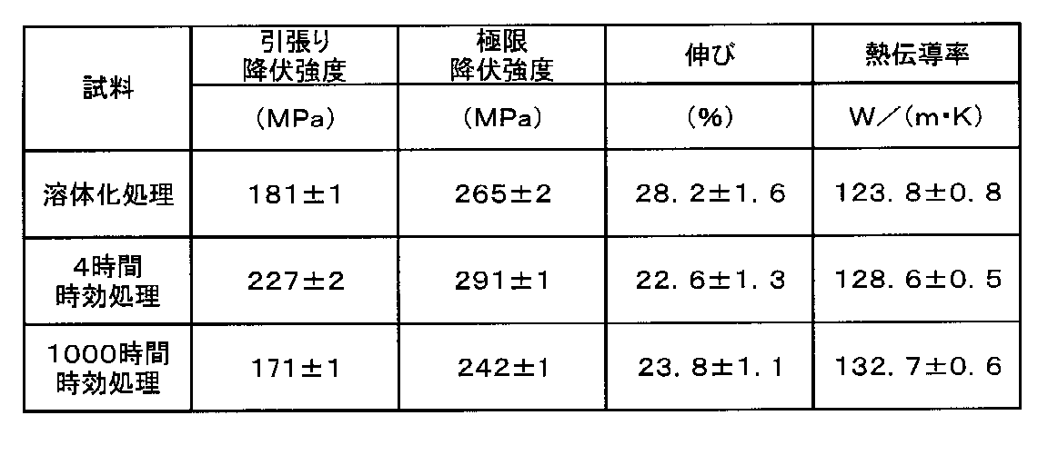
図7は、実施例6の4時間の時効処理をした時効処理材と他の市販の展伸合金における引張降伏強度と熱伝導との関係を示す図である。図7に示すように、4時間の時効処理をした時効処理材(T6)は他の市販の鍛造合金と比較して、引張降伏強度と熱伝導率のバランスが優れていることが分かった。
実施例6は、実施例3のZn濃度を0.8質量%から1.6質量%に増加した場合である。溶体化処理後は120W/(m・K)程度の熱伝導率だが、時効処理をすることで130W/(m・K)を超える熱伝導率を達成することができることを示す例である。
実施例6は、実施例3のZn濃度を0.8質量%から1.6質量%に増加した場合である。溶体化処理後は120W/(m・K)程度の熱伝導率だが、時効処理をすることで130W/(m・K)を超える熱伝導率を達成することができることを示す例である。
実施例6を含む本発明のマグネシウム合金は、母相となる材料を溶体化処理後に急冷することで過飽和固溶体を形成させ、その後の時効処理によって過飽和に固溶した溶質元素を高密度に分散した微細なG.P.ゾーン析出物又はG.P.析出物として析出することで時効処理材(T6)の機械的な強度が増加する。さらに、G.P.析出物の形成に伴い、マグネシウム母相に固溶しているCa、Zn、Zr等の溶質元素の量は低下するため、熱伝導性の低下の一因となる溶質元素の量は低下する。これにより、時効処理による時効硬化を用いると、強度と共に熱伝導率も向上させることができた。この原理はすでにアルミニウム合金等に用いられており、本発明はマグネシウム合金にも適用できることを見出した。
(実施例7)
(1)合金組成:Mg-1.6Zn-0.5Ca-0.4Mn
(2)均質化処理:300℃で4時間保持後、7.5℃/hで昇温し、450℃で6時間保持、300℃まで空冷後に水冷した。
(3)溶体化処理:400℃で1時間
(4)時効処理:170℃で16時間、500時間
上述の実験手順に従って試料を作製し、表1に記載の通り均質化処理として300℃で4時間保持後に7.5℃/hで昇温し、さらに450℃で6時間保持し、300℃まで空冷後に水冷した。その後、板状試料を作製し、450℃で2時間の条件で溶体化処理を行った。溶体化処理材と、溶体化処理材に対して170℃で16時間の時効処理した時効処理材と、500時間の時効処理した時効処理材との、各試料の熱伝導率を測定した。その結果、上記各試料の熱伝導率は、それぞれ112.6W/(m・K)、117.2W/(m・K)、124.7W/(m・K)で、時効処理によって熱伝導率の上昇がみられた。実施例7の合金組成は実施例6のZrをMnに代えた例である。ZrをMnに代えることで熱伝導率の値は低下するが、時効処理を行うと120W/(m・K)を超える熱伝導率を達成できた。しかしながら、微細化剤としては、好ましくはMnではなくZrを加えるのが良いことが分かった。
(実施例8)
(1)合金組成:Mg-1.6Zn-0.5Ca-0.4Zr-0.3Gd
(2)均質化処理:300℃で4時間保持後、7.5℃/hで昇温し、450℃で6時間保持、300℃まで空冷後に水冷した。
(3)溶体化処理:400℃で1時間
(4)時効処理:170℃で16時間、500時間
上述の実験手順に従って試料を作製し、表1に記載の通り、均質化処理として300℃で4時間保持後に7.5℃/hで昇温し、さらに450℃で6時間保持し、300℃まで空冷後に水冷した。その後、板状試料を作製し、450℃で2時間の条件で溶体化処理を行った。
溶体化処理材と、溶体化処理材に対して170℃で16時間の時効処理した時効処理材と、500時間の時効処理した時効処理材との、各試料の熱伝導率を測定した。その結果、上記各試料の熱伝導率は、それぞれ112.6W/(m・K)、117.2W/(m・K)、124.7W/(m・K)であった。
実施例7の合金組成は実施例6の合金組成にGdを添加したものである。時効処理をすれば120W/(m・K)を超える熱伝導率を達成できるが、130W/(m・K)を超える熱伝導率を達成するには、余分な元素を加えない方が良いことが分かった。
(実施例9)
(1)合金組成:Mg-1.6Zn-0.5Ca-0.4Zr
(2)均質化処理:300℃で4時間保持後、7.5℃/hで昇温し、450℃で6時間保持、300℃まで空冷後に水冷した。
(3)溶体化処理:400℃で1時間
(4)時効処理:170℃で6時間、500時間
上述の実験手順に従って試料を作製し、表1に記載の通り均質化処理として300℃で4時間保持後に7.5℃/hで昇温し、さらに450℃で6時間保持し、300℃まで空冷後に水冷した。その後均質化処理材を450℃で2時間の条件で溶体化処理を行った。
溶体化処理材と、溶体化処理材に対して170℃で6時間の時効処理した時効処理材と、500時間の時効処理した時効処理材との、各試料の熱伝導率を測定した。その結果、上記各試料の熱伝導率は、それぞれ110.7W/(m・K)、126.5W/(m・K)、135.7W/(m・K)であった。
実施例9は実施例6と組成は同じであるが、板状試料にはしないで均質化処理を行った。実施例9は、板状試料を作製するために圧延工程等をしない場合においても熱伝導率に影響を与えないことを示す例である。
(比較例1)
(1)合金組成:Mg-3.0Zn-0.5Ca-0.4Zr
(2)均質化処理:300℃で4時間保持後、7.5℃/hで昇温し、450℃で6時間保持した。
(3)溶体化処理:400℃で2時間
(4)時効処理:170℃で10時間、500時間
上述の実験手順に従って試料を作製し、表1に記載の通り均質化処理として300℃で4時間保持後、7.5℃/hで昇温し、450℃で6時間保持し、水冷した。その後、板状試料を作製し、400℃で2時間の条件で溶体化処理を行った。
溶体化処理材と、溶体化処理材に対して170℃で10時間の時効処理した時効処理材と、500時間の時効処理した時効処理材との、各試料の熱伝導率を測定した。その結果、上記各試料の熱伝導率は、それぞれ115.3W/(m・K)、116.8W/(m・K)、129.5W/(m・K)であった。
比較例1はZn濃度の上限を示す例であり、実施例6よりもZn添加量を増加した場合である。これにより3質量%のZnを添加すると、時効処理によって熱伝導率を向上させることはできるものの、170℃で10時間の時効処理では、120W/(m・K)より高い値は得られない。
(比較例2)
(1)合金組成:Mg-3.0Al-0.7Zn-0.4Ca-0.3Mn
(2)溶体化処理:400℃で1時間
上述の実験手順に従って試料を作製し、400℃で1時間溶体化処理を行った。熱伝導率の測定は溶体化処理材に対して行った。その結果、熱伝導率の値は、85.6W/(m・K)であった。比較例2は比較例1のZnの9割をAlで置換した場合であり、ZnをAlに置換すると、熱伝導率は著しく低下するので、合金元素としてAlよりZnの方が好ましいことを示している。
(1)合金組成:Mg-3.0Al-0.7Zn-0.4Ca-0.3Mn
(2)溶体化処理:400℃で1時間
上述の実験手順に従って試料を作製し、400℃で1時間溶体化処理を行った。熱伝導率の測定は溶体化処理材に対して行った。その結果、熱伝導率の値は、85.6W/(m・K)であった。比較例2は比較例1のZnの9割をAlで置換した場合であり、ZnをAlに置換すると、熱伝導率は著しく低下するので、合金元素としてAlよりZnの方が好ましいことを示している。
(比較例3)
(1)合金組成:Mg-4.0Zn-0.5Ca-0.4Zr
(2)均質化処理:300℃で4時間保持後、7.5℃/hで昇温し、350℃で20時間保持した。
(3)溶体化処理:400℃で1時間
(4)時効処理:170℃で10時間、500時間
上述の実験手順に従って試料を作製し、表1に記載の通り均質化処理として300℃で4時間保持後、7.5℃/hで昇温し、350℃で20時間保持し水冷した。その後、板状試料を作製し、450℃で2時間の条件で溶体化処理を行った。
溶体化処理材と、溶体化処理材に対して170℃で10時間の時効処理した時効処理材と、500時間の時効処理した時効処理材との、各試料の熱伝導率を測定した。その結果、上記各試料の熱伝導率は、それぞれ114.6W/(m・K)、119.5W/(m・K)、124.1W/(m・K)であった。比較例3はZn濃度の上限を示す例であり、実施例及び比較例1よりもZnの添加量を増加したものである。これにより4質量%のZnを添加すると、時効処理によって熱伝導率を向上させることはできるものの、170℃で10時間の時効処理では、120W/(m・K)より高い値は得られなかった。
本発明は、上記実施の形態に限定されるものではなく、特許請求の範囲に記載した発明の範囲内で種々の変形が可能であり、それらも本発明の範囲内に含まれることはいうまでもない。
Claims (12)
- 1質量%以下のCaと3質量%以下のZnとを含有し、残部がMg及び不可避不純物からなり、
Mg、Ca及びZnよりなるG.P.ゾーンがマグネシウム母相の(0001)面上に分散しており、
前記G.P.ゾーンは、(0001)面において長手方向が4.0から5.0nm以上であり、数密度が1×10²⁰から1×1024m-3の範囲である、マグネシウム合金時効処理材。 - 0.5質量%以上1質量%以下のCaと、0.8質量%以上3質量%以下のZnと、を含有し、残部がMg及び不可避不純物からなる、請求項1に記載のマグネシウム合金時効処理材。
- 前記マグネシウム合金時効処理材の熱伝導率は、120W/(m・K)以上である、請求項1に記載のマグネシウム合金時効処理材。
- さらに、ジルコニウム又はマンガンを含む、請求項1乃至3の何れかに記載のマグネシウム合金時効処理材。
- さらに、ガドリニウム又はセリウムを含む、請求項1乃至4の何れかに記載のマグネシウム合金時効処理材。
- Mg、Zn及びCaを溶解して鋳造固体を得る工程と、
前記鋳造固体を均質化処理して均質化処理材を得る工程と、
前記均質化処理材を時効処理してマグネシウム合金時効処理材を得る工程と、
を含み、
前記マグネシウム合金時効処理材の組成が、1質量%以下のCaと、3質量%以下のZnと、を含有し、残部がMg及び不可避不純物からなる、マグネシウム合金時効処理材の製造方法。 - 前記時効処理を、140℃から250℃の温度範囲で前記マグネシウム合金時効処理材の熱伝導率が120W/(m・K)以上になるまで行う、請求項6に記載のマグネシウム合金時効処理材の製造方法。
- 前記均質化処理材を得る工程と前記マグネシウム合金時効処理材を得る工程との間において、前記均質化処理材を溶体化処理して溶体化処理材を得る工程を挿入する、請求項6又は7に記載のマグネシウム合金時効処理材の製造方法。
- 前記均質化処理材を得る工程と前記溶体化処理材を得る工程との間において、前記均質化処理材を展伸加工する工程を挿入する、請求項8に記載のマグネシウム合金時効処理材の製造方法。
- 前記均質化処理を、300℃以上500℃以下で所定時間行う、請求項6に記載のマグネシウム合金時効処理材の製造方法。
- 請求項1に記載のマグネシウム合金時効処理材を使用した筐体又はパネル材を有するOA機器。
- 請求項1に記載のマグネシウム合金時効処理材を使用した輸送機器及びその部品。
Priority Applications (1)
| Application Number | Priority Date | Filing Date | Title |
|---|---|---|---|
| JP2021562614A JP7760123B2 (ja) | 2019-12-03 | 2020-11-26 | マグネシウム合金時効処理材及びその製造方法、並びにそれを使用したoa機器、輸送機器及びその部品 |
Applications Claiming Priority (2)
| Application Number | Priority Date | Filing Date | Title |
|---|---|---|---|
| JP2019-219147 | 2019-12-03 | ||
| JP2019219147 | 2019-12-03 |
Publications (1)
| Publication Number | Publication Date |
|---|---|
| WO2021111989A1 true WO2021111989A1 (ja) | 2021-06-10 |
Family
ID=76221619
Family Applications (1)
| Application Number | Title | Priority Date | Filing Date |
|---|---|---|---|
| PCT/JP2020/044106 Ceased WO2021111989A1 (ja) | 2019-12-03 | 2020-11-26 | マグネシウム合金時効処理材及びその製造方法、並びにそれを使用したoa機器、輸送機器及びその部品 |
Country Status (2)
| Country | Link |
|---|---|
| JP (1) | JP7760123B2 (ja) |
| WO (1) | WO2021111989A1 (ja) |
Cited By (1)
| Publication number | Priority date | Publication date | Assignee | Title |
|---|---|---|---|---|
| CN121700215A (zh) * | 2026-02-11 | 2026-03-20 | 兰州理工大学 | 一种高性能镁合金及其制备方法 |
Citations (4)
| Publication number | Priority date | Publication date | Assignee | Title |
|---|---|---|---|---|
| WO2008016150A1 (fr) * | 2006-08-03 | 2008-02-07 | National Institute For Materials Science | Alliage de magnésium et son procédé de fabrication |
| JP2015526592A (ja) * | 2012-06-26 | 2015-09-10 | バイオトロニック アクチェンゲゼルシャフト | マグネシウム合金、その製造方法およびその使用 |
| WO2019163161A1 (ja) * | 2018-02-21 | 2019-08-29 | 国立研究開発法人物質・材料研究機構 | マグネシウム合金及びマグネシウム合金の製造方法 |
| WO2019172047A1 (ja) * | 2018-03-03 | 2019-09-12 | 国立研究開発法人物質・材料研究機構 | マグネシウム合金時効処理材とその製造方法 |
-
2020
- 2020-11-26 WO PCT/JP2020/044106 patent/WO2021111989A1/ja not_active Ceased
- 2020-11-26 JP JP2021562614A patent/JP7760123B2/ja active Active
Patent Citations (4)
| Publication number | Priority date | Publication date | Assignee | Title |
|---|---|---|---|---|
| WO2008016150A1 (fr) * | 2006-08-03 | 2008-02-07 | National Institute For Materials Science | Alliage de magnésium et son procédé de fabrication |
| JP2015526592A (ja) * | 2012-06-26 | 2015-09-10 | バイオトロニック アクチェンゲゼルシャフト | マグネシウム合金、その製造方法およびその使用 |
| WO2019163161A1 (ja) * | 2018-02-21 | 2019-08-29 | 国立研究開発法人物質・材料研究機構 | マグネシウム合金及びマグネシウム合金の製造方法 |
| WO2019172047A1 (ja) * | 2018-03-03 | 2019-09-12 | 国立研究開発法人物質・材料研究機構 | マグネシウム合金時効処理材とその製造方法 |
Cited By (1)
| Publication number | Priority date | Publication date | Assignee | Title |
|---|---|---|---|---|
| CN121700215A (zh) * | 2026-02-11 | 2026-03-20 | 兰州理工大学 | 一种高性能镁合金及其制备方法 |
Also Published As
| Publication number | Publication date |
|---|---|
| JPWO2021111989A1 (ja) | 2021-06-10 |
| JP7760123B2 (ja) | 2025-10-27 |
Similar Documents
| Publication | Publication Date | Title |
|---|---|---|
| Kimura et al. | Microstructures and mechanical properties of aluminum-transition metal binary alloys (Al-Fe, Al-Mn, and Al-Cr) processed by laser powder bed fusion | |
| Shen et al. | Effect of heat treatment on microstructure and mechanical properties of Mg-6Gd-3Y-0.5 Zr alloy fabricated by wire arc additive manufacturing | |
| Geng et al. | Microstructural evolution and strengthening mechanism of high-strength AlSi8. 1 Mg1. 4 alloy produced by selective laser melting | |
| CN103710580B (zh) | 高强度铝合金挤压材料及其制造方法 | |
| CN110945154B (zh) | 镁基合金延展材料及其制造方法 | |
| WO2013115490A1 (ko) | 고연성 및 고인성의 마그네슘 합금 및 이의 제조방법 | |
| JP7785366B2 (ja) | マグネシウム合金時効処理材とその製造方法 | |
| TW201833342A (zh) | 用於高強度鋁合金之等通道彎角擠製(ecae)材料 | |
| WO2013180122A1 (ja) | マグネシウム合金、マグネシウム合金部材並びにその製造方法、マグネシウム合金の使用方法 | |
| CN111989415A (zh) | 用于具有优异的碰撞性能和高屈服强度的挤压件的6xxx铝合金及其制备方法 | |
| Paulisch et al. | The influence of natural aging and repeated solution annealing on microstructure and mechanical properties of hot extruded alloys Al 7020 and Al 7175 | |
| JP7116394B2 (ja) | マグネシウム合金及びマグネシウム合金の製造方法 | |
| Tu et al. | Microstructure and mechanical properties of Mg-12Gd-3Y-0.4 Zr magnesium alloy with layered heterogeneous microstructure fabricated by wire arc additive manufacturing | |
| Xu et al. | Additive manufacturing high-strength and ultra-high-rare-earth magnesium alloys: Excellent long-time aging hardening and strengthening behavior | |
| Qin et al. | Microstructure and mechanical properties evolution of a novel selective laser melted Al-Cu-Ni-Zr-Ti alloy during heat treatment | |
| JP7076731B2 (ja) | マグネシウム合金及びマグネシウム合金の製造方法 | |
| JP7760123B2 (ja) | マグネシウム合金時効処理材及びその製造方法、並びにそれを使用したoa機器、輸送機器及びその部品 | |
| Kord et al. | Microstructure and mechanical behavior of as cast and hot extruded AlZnMgCu alloy with rare earth erbium additions | |
| KR101680046B1 (ko) | 소성 가공 전 시효 처리에 의한 고강도 마그네슘 합금 가공재 제조방법 및 이에 의해 제조된 고강도 마그네슘 합금 가공재 | |
| Zhang et al. | The microstructure evolution and mechanical properties improvement of the AZ61 alloy by adding Sc | |
| Shi et al. | Achieving the coexistence of multiple strengthening mechanisms in a dual-phase Mg-Li via rapid solidification | |
| JP5419061B2 (ja) | マグネシウム合金 | |
| Mengiste et al. | Achieving significant grain refinement in industrially oriented Al-Mg-Si-Fe alloys using a scalable special cooling medium | |
| JP6843353B2 (ja) | Mg合金とその製造方法 | |
| JP4996854B2 (ja) | 高温高速成形用アルミニウム合金材及びその製造方法、並びにアルミニウム合金成形品の製造方法 |
Legal Events
| Date | Code | Title | Description |
|---|---|---|---|
| 121 | Ep: the epo has been informed by wipo that ep was designated in this application |
Ref document number: 20896758 Country of ref document: EP Kind code of ref document: A1 |
|
| ENP | Entry into the national phase |
Ref document number: 2021562614 Country of ref document: JP Kind code of ref document: A |
|
| NENP | Non-entry into the national phase |
Ref country code: DE |
|
| 122 | Ep: pct application non-entry in european phase |
Ref document number: 20896758 Country of ref document: EP Kind code of ref document: A1 |