WO2021111792A1 - 表示装置及び表示システム - Google Patents
表示装置及び表示システム Download PDFInfo
- Publication number
- WO2021111792A1 WO2021111792A1 PCT/JP2020/041188 JP2020041188W WO2021111792A1 WO 2021111792 A1 WO2021111792 A1 WO 2021111792A1 JP 2020041188 W JP2020041188 W JP 2020041188W WO 2021111792 A1 WO2021111792 A1 WO 2021111792A1
- Authority
- WO
- WIPO (PCT)
- Prior art keywords
- range
- light
- display
- display device
- pupil
- Prior art date
- Legal status (The legal status is an assumption and is not a legal conclusion. Google has not performed a legal analysis and makes no representation as to the accuracy of the status listed.)
- Ceased
Links
Images










Classifications
-
- G—PHYSICS
- G02—OPTICS
- G02C—SPECTACLES; SUNGLASSES OR GOGGLES INSOFAR AS THEY HAVE THE SAME FEATURES AS SPECTACLES; CONTACT LENSES
- G02C7/00—Optical parts
- G02C7/02—Lenses; Lens systems ; Methods of designing lenses
- G02C7/08—Auxiliary lenses; Arrangements for varying focal length
- G02C7/081—Ophthalmic lenses with variable focal length
- G02C7/083—Electrooptic lenses
-
- A—HUMAN NECESSITIES
- A61—MEDICAL OR VETERINARY SCIENCE; HYGIENE
- A61F—FILTERS IMPLANTABLE INTO BLOOD VESSELS; PROSTHESES; DEVICES PROVIDING PATENCY TO, OR PREVENTING COLLAPSING OF, TUBULAR STRUCTURES OF THE BODY, e.g. STENTS; ORTHOPAEDIC, NURSING OR CONTRACEPTIVE DEVICES; FOMENTATION; TREATMENT OR PROTECTION OF EYES OR EARS; BANDAGES, DRESSINGS OR ABSORBENT PADS; FIRST-AID KITS
- A61F2/00—Filters implantable into blood vessels; Prostheses, i.e. artificial substitutes or replacements for parts of the body; Appliances for connecting them with the body; Devices providing patency to, or preventing collapsing of, tubular structures of the body, e.g. stents
- A61F2/02—Prostheses implantable into the body
- A61F2/14—Eye parts, e.g. lenses or corneal implants; Artificial eyes
- A61F2/16—Intraocular lenses
- A61F2/1613—Intraocular lenses having special lens configurations, e.g. multipart lenses; having particular optical properties, e.g. pseudo-accommodative lenses, lenses having aberration corrections, diffractive lenses, lenses for variably absorbing electromagnetic radiation, lenses having variable focus
-
- G—PHYSICS
- G02—OPTICS
- G02B—OPTICAL ELEMENTS, SYSTEMS OR APPARATUS
- G02B27/00—Optical systems or apparatus not provided for by any of the groups G02B1/00 - G02B26/00, G02B30/00
- G02B27/01—Head-up displays
- G02B27/017—Head mounted
- G02B27/0172—Head mounted characterised by optical features
-
- G—PHYSICS
- G02—OPTICS
- G02C—SPECTACLES; SUNGLASSES OR GOGGLES INSOFAR AS THEY HAVE THE SAME FEATURES AS SPECTACLES; CONTACT LENSES
- G02C7/00—Optical parts
- G02C7/02—Lenses; Lens systems ; Methods of designing lenses
- G02C7/04—Contact lenses for the eyes
-
- G—PHYSICS
- G02—OPTICS
- G02F—OPTICAL DEVICES OR ARRANGEMENTS FOR THE CONTROL OF LIGHT BY MODIFICATION OF THE OPTICAL PROPERTIES OF THE MEDIA OF THE ELEMENTS INVOLVED THEREIN; NON-LINEAR OPTICS; FREQUENCY-CHANGING OF LIGHT; OPTICAL LOGIC ELEMENTS; OPTICAL ANALOGUE/DIGITAL CONVERTERS
- G02F1/00—Devices or arrangements for the control of the intensity, colour, phase, polarisation or direction of light arriving from an independent light source, e.g. switching, gating or modulating; Non-linear optics
- G02F1/01—Devices or arrangements for the control of the intensity, colour, phase, polarisation or direction of light arriving from an independent light source, e.g. switching, gating or modulating; Non-linear optics for the control of the intensity, phase, polarisation or colour
- G02F1/13—Devices or arrangements for the control of the intensity, colour, phase, polarisation or direction of light arriving from an independent light source, e.g. switching, gating or modulating; Non-linear optics for the control of the intensity, phase, polarisation or colour based on liquid crystals, e.g. single liquid crystal display cells
- G02F1/133—Constructional arrangements; Operation of liquid crystal cells; Circuit arrangements
- G02F1/136—Liquid crystal cells structurally associated with a semi-conducting layer or substrate, e.g. cells forming part of an integrated circuit
- G02F1/1362—Active matrix addressed cells
- G02F1/136286—Wiring, e.g. gate line, drain line
-
- A—HUMAN NECESSITIES
- A61—MEDICAL OR VETERINARY SCIENCE; HYGIENE
- A61F—FILTERS IMPLANTABLE INTO BLOOD VESSELS; PROSTHESES; DEVICES PROVIDING PATENCY TO, OR PREVENTING COLLAPSING OF, TUBULAR STRUCTURES OF THE BODY, e.g. STENTS; ORTHOPAEDIC, NURSING OR CONTRACEPTIVE DEVICES; FOMENTATION; TREATMENT OR PROTECTION OF EYES OR EARS; BANDAGES, DRESSINGS OR ABSORBENT PADS; FIRST-AID KITS
- A61F2/00—Filters implantable into blood vessels; Prostheses, i.e. artificial substitutes or replacements for parts of the body; Appliances for connecting them with the body; Devices providing patency to, or preventing collapsing of, tubular structures of the body, e.g. stents
- A61F2/02—Prostheses implantable into the body
- A61F2/14—Eye parts, e.g. lenses or corneal implants; Artificial eyes
- A61F2/16—Intraocular lenses
-
- G—PHYSICS
- G02—OPTICS
- G02B—OPTICAL ELEMENTS, SYSTEMS OR APPARATUS
- G02B27/00—Optical systems or apparatus not provided for by any of the groups G02B1/00 - G02B26/00, G02B30/00
- G02B27/01—Head-up displays
- G02B27/0101—Head-up displays characterised by optical features
- G02B2027/0123—Head-up displays characterised by optical features comprising devices increasing the field of view
-
- G—PHYSICS
- G02—OPTICS
- G02B—OPTICAL ELEMENTS, SYSTEMS OR APPARATUS
- G02B27/00—Optical systems or apparatus not provided for by any of the groups G02B1/00 - G02B26/00, G02B30/00
- G02B27/01—Head-up displays
- G02B27/0101—Head-up displays characterised by optical features
- G02B2027/0132—Head-up displays characterised by optical features comprising binocular systems
- G02B2027/0134—Head-up displays characterised by optical features comprising binocular systems of stereoscopic type
-
- G—PHYSICS
- G02—OPTICS
- G02C—SPECTACLES; SUNGLASSES OR GOGGLES INSOFAR AS THEY HAVE THE SAME FEATURES AS SPECTACLES; CONTACT LENSES
- G02C2202/00—Generic optical aspects applicable to one or more of the subgroups of G02C7/00
- G02C2202/20—Diffractive and Fresnel lenses or lens portions
-
- G—PHYSICS
- G02—OPTICS
- G02C—SPECTACLES; SUNGLASSES OR GOGGLES INSOFAR AS THEY HAVE THE SAME FEATURES AS SPECTACLES; CONTACT LENSES
- G02C7/00—Optical parts
- G02C7/14—Mirrors; Prisms
Definitions
- the technology according to the present disclosure (hereinafter, also referred to as “the present technology”) relates to a display device and a display system.
- Patent Documents 1 and 2 disclose a technique for improving the visual acuity of a peripheral visual field by correcting the aberration of light rays reaching the peripheral visual field (peripheral portion of the visual field range).
- Patent Documents 1 and 2 it is not possible to display and visually recognize information in a range wider than the visual field range.
- the main purpose of this technology is to provide a display device and the display system capable of displaying and visually recognizing information in a range wider than the visual field range.
- the present technology can irradiate at least a range outside the ambient light irradiation range within a range wider than the ambient light irradiation range, including an ambient light irradiation range in which the ambient light is irradiated through the pupil in the retina.
- a display device provided with a light irradiation system.
- the ambient light irradiation range may be determined by a portion of the face around the retina that prevents the ambient light from reaching the retina and / or an object worn on the face or head. Even if the light irradiation system can irradiate any of the pupil-side range, the ambient light irradiation range, and the pupil-side range with respect to the ambient light irradiation range in the retina. Good.
- the light irradiation system is selectively selected from the ambient light irradiation range, the pupil-side range of the ambient light irradiation range in the retina, and the ambient light irradiation range and the range spanning the pupil-side range. It may be possible to irradiate the retina with light.
- the light irradiation system may emit light so that the light intersects in the vicinity of the pupil.
- the light irradiation system may irradiate a range of the retina of one eye opposite to the other eye side.
- the light irradiation system may include at least a display element integrated with the eyeball during use.
- the display element may exhibit a viewing angle characteristic that makes the visibility of the peripheral portion lower than the visibility of the central portion in a viewing range corresponding to a range wider than the ambient light irradiation range.
- the display element may be a contact lens type display element.
- the display element may be an intraocular lens type display element.
- the display element may include a plurality of pixels arranged in two dimensions or three dimensions.
- the display element may have a transmitting portion that transmits at least a part of light in a specific wavelength band and a light-shielding portion that blocks the light.
- the transmissive portion may be a gap between the pixels.
- the light-shielding portion may be a gap between the pixels.
- the transmissive portion may be wiring arranged between the pixels.
- the light-shielding portion may be wiring arranged between the pixels.
- the transmissive portion may be a wiring between a pixel group composed of at least two pixels.
- the light-shielding portion may be wiring between a pixel group composed of at least two pixels.
- the plurality of pixels may be arranged in a staggered pattern.
- the display element is a self-luminous display element.
- the display element includes a liquid crystal display unit and a light source.
- a sensor for detecting information outside the normal visual field range which is information outside the normal visual field range corresponding to the ambient light irradiation range, is further provided.
- the light irradiation system may include at least an optical element integrated with the eyeball during use and a light projection unit that projects light toward the optical element.
- the optical element may exhibit a viewing angle characteristic that makes the visibility of the peripheral portion lower than the visibility of the central portion in a viewing range corresponding to a range wider than the ambient light irradiation range.
- the optical element may be a contact lens type optical element.
- the optical element may be an intraocular lens type optical element.
- the present technology includes the display device, a control device for controlling the display device, and the like. A display system is also provided.
- FIG. 1A is a diagram for explaining a conventional vertical visual field range.
- FIG. 1B is a diagram for explaining a conventional lateral viewing range. It is a cross-sectional view of an eyeball.
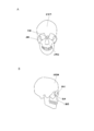
- FIG. 3A is a schematic front view of the skull.
- FIG. 3B is a schematic right side view of the skull. It is a figure for demonstrating the vertical ambient light irradiation range in the retina. It is a figure for demonstrating the lateral ambient light irradiation range in the retina. It is a viewing angle distribution map which shows the normal visual field range of both eyes.
- FIG. 1A is a diagram for explaining a conventional vertical visual field range.
- FIG. 1B is a diagram for explaining a conventional lateral viewing range. It is a cross-sectional view of an eyeball.
- FIG. 3A is a schematic front view of the skull.
- FIG. 3B is a schematic right side view of the skull. It is a figure for demonstrating the vertical ambient light irradiation range
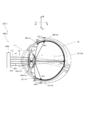
- FIG. 5 is a vertical cross-sectional view showing a state in which light is irradiated to the retina from a display element mounted on an eyeball in the display device according to the first embodiment of the present technology.
- FIG. 5 is a cross-sectional view showing a state in which light is irradiated to the retina from a display element mounted on an eyeball in the display device according to the first embodiment of the present technology.
- It is sectional drawing which shows the structural example 1 of the display element of the display device which concerns on 1st Embodiment of this technique.
- It is sectional drawing which shows the structural example 2 of the display element of the display device which concerns on 1st Embodiment of this technique.
- FIG. 2 It is a figure which shows the pixel arrangement example 2 of a display element. It is a figure which shows the pixel arrangement example 3 of a display element. It is a figure which shows the pixel arrangement example 4 of a display element. It is a figure which shows the pixel arrangement example 5 of a display element. It is a figure which shows the pixel arrangement example 6 of a display element. It is a figure which shows the pixel arrangement example 7 of a display element. It is a block diagram which shows an example of the function of the display system including the display device which concerns on 1st Embodiment of this technique.
- FIG. 1 shows the pixel arrangement example 2 of a display element.
- FIG. 4 It is a figure which shows the pixel arrangement example 4 of a display element. It is a figure which shows the pixel arrangement example 5 of a display element. It is a figure which shows the pixel arrangement example 6 of a display element. It is a figure which shows the pixel arrangement example 7 of a display element.
- FIG. 19A is a diagram showing an extended visual field range wider than the normal visual field range in the vertical direction in which information can be displayed by the display device according to the first embodiment of the present technology.
- FIG. 19B is a diagram showing an extended visual field range wider than the normal visual field range in the lateral direction in which information can be displayed by the display device according to the first embodiment of the present technology. It is a figure which shows the extended visual field range of the right eye which can display information by the display device of this technology by an arrow. It is a figure which shows the extended visual field range of the right eye which can display information by the display device of this technology by area. It is a figure which shows the extended maximum virtual visual field range of the right eye and the extended visual field range of the right eye which can display information by the display device of this technology.
- FIG. 5 is a vertical cross-sectional view showing a state in which light projected from a light projection unit is applied to the retina via an optical element mounted on an eyeball in a display device according to a second embodiment of the present technology.
- FIG. 5 is a cross-sectional view showing a state in which light projected from a light projection unit irradiates the retina via an optical element mounted on an eyeball in a display device according to a second embodiment of the present technology. It is a block diagram which shows an example of the function of the display system including the display device which concerns on 2nd Embodiment of this technique.
- FIG. 5 is a cross-sectional view showing a state in which light is irradiated to the retina from a display element embedded in an eyeball in the display device according to the first embodiment of the third embodiment of the present technology.
- FIG. 5 is a cross-sectional view showing a state in which light is irradiated to the retina from a display element embedded in an eyeball in the display device according to the second embodiment of the third embodiment of the present technology.
- FIG. 5 is a cross-sectional view showing a state in which light is irradiated to the retina from a display element embedded in an eyeball in the display device according to the third embodiment of the third embodiment of the present technology.
- FIG. 5 is a cross-sectional view showing a state in which light is irradiated to the retina from a display element embedded in an eyeball in the display device according to the fourth embodiment of the third embodiment of the present technology.
- FIG. 5 is a cross-sectional view showing a state in which light is irradiated to the retina from a display element embedded in an eyeball in the display device according to the first embodiment of the fourth embodiment of the present technology.
- FIG. 5 is a cross-sectional view showing a state in which light is irradiated to the retina from a display element embedded in an eyeball in the display device according to the second embodiment of the fourth embodiment of the present technology.
- FIG. 5 is a cross-sectional view showing a state in which light is irradiated to the retina from a display element embedded in an eyeball in the display device according to the third embodiment of the fourth embodiment of the present technology.
- FIG. 5 is a cross-sectional view showing a state in which light is irradiated to the retina from a display element embedded in an eyeball in the display device according to the fourth embodiment of the fourth embodiment of the present technology.
- FIG. 5 is a cross-sectional view showing a state in which light is irradiated to the retina from a display element embedded in an eyeball in the display device according to the fifth embodiment of the fourth embodiment of the present technology.
- FIG. 5 is a cross-sectional view showing a state in which light is irradiated to the retina from a display element embedded in an eyeball in the display device according to the sixth embodiment of the fourth embodiment of the present technology. It is a figure which shows an example of the extended visual field range when the retina is irradiated with light from the display device of this technology.
- the visual field range of a human being is usually limited by the angle of light rays of ambient light that can enter the retinas of both eyes.
- the ambient light refers to light such as natural light such as sunlight and artificial light such as illumination light.
- Most humans rely on visual information within this certain visual field to perform various activities.
- the visual field range is further limited, which may hinder activities.
- the normal visual field range is secured, if the information outside the visual field range can be visually recognized, the presence or absence of an obstacle or the like can be recognized in a wider range, so that there is an advantage that safety can be improved. Therefore, after diligent studies, the inventor has developed a display device of the present technology as a display device capable of displaying and visually recognizing information in a range wider than the visual field range.
- the direction from the back side to the front side of the face is the front direction
- the direction from the front side to the back side of the face is the rear direction
- the direction from the upper side to the lower side of the face is the downward direction
- the bottom of the face is the upward direction
- the direction from the left side to the right side of the face is the right direction
- the direction from the right side to the left side of the face is the left direction.
- the visual field range of each eye in the normal vertical direction (for example, the vertical direction, the same applies hereinafter) is, for example, as shown in FIG.
- the normal lateral (for example, horizontal direction, the same applies hereinafter) visual field range of the right eye forms an angle of, for example, 100 ° to the right with respect to the line-of-sight direction facing directly in front, as shown in FIG. 1B, for example.
- the normal lateral visual field range of the left eye is, for example, as shown in FIG. 1B, the left visual field limit (at that angle) forming an angle of, for example, 100 ° to the left with respect to the line-of-sight direction facing directly in front.
- the light beam incident on the eyeball EB reaches the retina 1 via the cornea 5, the pupil 4, the crystalline lens 6 and the vitreous body 7. .. Human vision is generated when the light emitted to the retina 1 is converted into an electrical signal by the photoreceptor cells of the retina 1 and transmitted to the visual cortex of the brain via the optic nerve 8.
- the retina 1 extends over substantially the entire area from the fundus to the ciliary body adjacent to the periphery of the crystalline lens (position adjacent to the ciliary body shown in the cross section of the eyeball) in the eyeball EB (substantially).
- the range of ambient light that is irradiated to the retina 1 through the pupil 4 is limited by, for example, the face or the head, and only light rays from a certain range reach the retina 1 as an image through the pupil 4.
- a certain range in which the light rays of the ambient light reach the retina 1 through the pupil 4 is a normal visual field range (hereinafter, also referred to as a “normal visual field range”).
- the range in which the ambient light is irradiated through the pupil 4 in the retina 1 is also referred to as an “ambient light irradiation range”.
- the ambient light irradiation range is the range of the retina 1 corresponding to the normal visual field range.
- the visual field is limited by the irregularities formed by the frontal bone on the upper side, the maxilla and cheekbone on the lower side, and the nasal bone on the horizontal medial side as shown in FIGS. 3A and 3B.
- the widest field of view is obtained because the only outside of such a field of view is not restricted by the skeleton.
- the structure of the eyeball is generally rotationally symmetric (see Fig. 2) except for the distribution of photoreceptor cells on the retina (different between the nasal side and the ear side). From this, it is considered that if there is no restriction due to the shape of the face or the head, vision can be obtained in the same range up, down, left and right, or in the range where the photoreceptor cells exist other than the range corresponding to the normal visual field range in the retina 1.
- the retina can be irradiated with light in a range that the ambient light does not reach (a region outside the ambient light irradiation range), vision can be obtained from photoreceptor cells in that range, and information is displayed and visually recognized in a range wider than the normal visual field range. It is thought that it can be made to do.
- the display device of this technology was developed to deal with the above first and second problems.
- FIG. 4 is a diagram for explaining an ambient light irradiation range of 10 V in the vertical direction (inside the vertical cross section) of the retina 1.
- the ambient light irradiation range within one longitudinal section of the retina of the left eye for example, the longitudinal section passing through the center of the pupil
- the ambient light irradiation range within the other longitudinal section of the retina of the left eye will be described.
- the vertical ambient light irradiation range 10V in the retina 1 of the left eye is a range having a substantially C-shaped vertical cross section having a cut on the pupil 4 side.
- the vertical ambient light irradiation range of the right eye is also a range having a substantially C-shaped vertical cross section with a cut on the pupil side.
- the position of the retina 1 reached by the ambient light AL that has passed through the pupil 4 is the lower end 10 Va of the vertical ambient light irradiation range 10 V in the retina 1 of the left eye.
- An environment in which the light enters the left eye from the lower visual field limit (the direction forming an angle of ⁇ 2 (for example, 60 ° to 65 °) downward with respect to the direction perpendicular to the radial direction of the pupil 4 (for example, the horizontal direction)) and passes through the pupil 4.
- the position of the retina 1 reached by the light AL is the upper end 10Vb of the vertical ambient light irradiation range 10V in the retina 1 of the left eye.
- FIG. 5 is a diagram for explaining a lateral ambient light irradiation range 10H in the retina.
- the ambient light irradiation range in one cross section of the retina of the left eye (for example, the cross section passing through the center of the pupil) will be described as an example, but the ambient light irradiation range in the other cross section of the retina of the left eye will be described.
- the lateral ambient light irradiation range 10H in the retina 1 of the left eye is a range having a substantially C-shaped cross section having a cut on the pupil 4 side.
- the ambient light irradiation range in the lateral retina of the right eye is also a range having a substantially C-shaped cross section with a cut on the pupil side.
- the left eye is incident on the left eye from a direction forming ⁇ 4 (for example, an angle of 90 ° to 95 °) to the left with respect to the direction perpendicular to the radial direction of the pupil 4.
- the position of the retina 1 reached by the ambient light AL that has passed through the pupil 4 is the right end 10Ha of the lateral ambient light irradiation range 10H in the retina 1 of the left eye.
- the left visual field limit (direction perpendicular to the radial direction of the pupil 4).
- the position of the retina 1 that is incident on the left eye from a direction forming an angle of ⁇ 3 (for example, 50 ° to 60 °) to the right and reaches the ambient light AL that has passed through the pupil 4 is the lateral direction of the retina 1 of the left eye. It is the left end 10Hb of the ambient light irradiation range 10H.
- it entered the eyeball of the right eye from the right visual field limit of the right eye (a direction forming an angle of, for example, 90 ° to 95 ° to the right with respect to the direction perpendicular to the radial direction of the pupil) and passed through the pupil.
- the position of the retina that the ambient light reaches is the left end of the lateral ambient light irradiation range in the retina of the right eye.
- the ambient light that enters the right eye from the right visual field limit of the right eye (the direction that forms an angle of, for example, 50 ° to 60 ° to the left with respect to the direction perpendicular to the radial direction of the pupil) and passes through the pupil arrives.
- the position of the retina is the right end of the lateral ambient light irradiation range in the retina of the right eye.
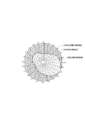
- FIG. 6 shows a normal visual field range corresponding to the ambient light irradiation range of each eye.
- the normal visual field range of the right eye is shown by a solid line
- the normal visual field range of the left eye is shown by a broken line.
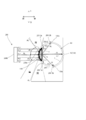
- FIG. 7 is a vertical cross-sectional view showing a state in which light is irradiated to the retina from a display element mounted on the eyeball in the display device according to the first embodiment of the present technology.
- FIG. 8 is a cross-sectional view showing a state in which light is irradiated to the retina from a display element mounted on the eyeball in the display device according to the first embodiment of the present technology. As shown in FIGS.
- the display device 50 irradiates the retina 1 with light (for example, display light) through the pupil 4 of the eyeball EB, and an image (virtual image) of the light. Is displayed.
- the display device 50 includes a light irradiation system 100 capable of irradiating the retina 1 with light (for example, image light) through the pupil 4.
- the light irradiation system 100 includes a display element 100a integrated with the eyeball at least during use. 7 and 8 show, as an example, a state in which the display element 100a is attached to the left eye.
- the display element 100a is, for example, a contact lens type display element.
- the display element 100a is attached to the eyeball EB so as to cover the cornea 5 and is used.
- the display element 100a has a transmitting portion that transmits at least a part of light having a specific wavelength (for example, visible light) and a shading portion that blocks the light.
- the ambient light AL passes through the display element 100a in a state where the display element 100a is attached to the user's eyeball EB, so that the user can visually recognize the actual scenery through the display element 100a.
- the display element 100a is, for example, a self-luminous display element, but may be configured to include a liquid crystal display unit and a light source that irradiates the liquid crystal display unit with light. More specifically, the display element 100a is, for example, a display element having an on-chip structure. 9 and 10 show configuration examples 1 and 2 (100a-1, 100a-2) of the display element 100a having an on-chip structure, respectively.
- the display elements 100a-1 are arranged on the second base material 120 side of the first and second base materials 110 and 120 and the first base material 110 arranged so as to face each other. It includes a pixel array 130 including a plurality of pixels 130a arranged two-dimensionally on a surface, and an optical element 140-1 arranged between each of the plurality of pixels 130a and a second base material 120.
- the first and second base materials 110 and 120 are made of a member (for example, a transparent or translucent lens material) that transmits at least a part of ambient light, and hold a pixel array 130 and a plurality of optical elements 140-1. And it has a function to protect.
- Each pixel 130a of the pixel array 130 includes light emitting elements such as an organic light emitting diode (OLED), an LED (light emitting diode), and a VCSEL (surface emitting laser).
- the pixel array may be referred to as a light emitting element array.
- the pixel array 130 outputs (lights) the pixels 130a based on the video information and outputs a display light DL that displays the video according to the video information.
- the optical element 140-1 of the display element 100a-1 is, for example, a collimated lens in which the light emitted from the corresponding pixel 130a is substantially parallel light.
- a ball-shaped lens is used as the collimating lens, but the lens is not limited to this, and may be a lens having another shape such as a biconvex lens, a plano-convex lens, or an aspherical lens.
- the display element 100a-1 is attached so that the second base material 120 is in close contact with the cornea 5 of the eyeball EB (curved along the cornea 5) during use. More specifically, the display element 100a-1 emits light in a direction perpendicular to the radial direction of the pupil 4, for example, so that the pixel 130a at the substantially center of the pixel array 130 faces the pupil 4 (for example, at the substantially center of the pupil 4). Is placed (to eject).
- the display element 100a-1 configured as described above is mounted on the eyeball EB and at least one pixel 130a of the pixel array 130 is driven (lit), light is emitted from the pixel 130a. ..
- the light emitted from the pixel 130a is regarded as substantially parallel light by the optical element 140-1, and is irradiated to the eyeball EB via the second base material 120.
- the display element 100a-2 is the same as the display element 100a-1 except that the optical elements 140-2 arranged between the first and second base materials 110 and 120 are different. It has a structure and a function.
- the optical element 140-2 is, for example, a refractive index distribution type lens.
- the display element 100a may be, for example, an ambient light irradiation range 10 and a pupil side range 20 (a range outside the ambient light irradiation range 10 in the retina 1, hereinafter, a “pupil side range” or a “pupil side range” It is possible to irradiate the entire area of the retina 1 including the side range 20) with the display light. More specifically, the display element 100a includes at least an ambient light in a range wider than the ambient light irradiation range 10 including the ambient light irradiation range 10 in the retina 1 (for example, the ambient light irradiation range 10V and 10H in the vertical and horizontal directions).
- the plurality of pixels 130a of the pixel array 130 of the display element 100a correspond to a range wider than the ambient light irradiation range 10 in the retina 1 (when all the pixels are driven, light is applied to substantially the entire range of the range. It is arranged in two or three dimensions (so that it can be irradiated).
- the "three-dimensional array” means, for example, that even if the display element 100a is arranged in a two-dimensional manner (arranged in a plane) when not in use, it is substantially curved when in use (when attached to the eyeball). It is assumed that they are arranged in three dimensions (the same applies hereinafter).
- the display element 100a can irradiate the ambient light irradiation range 10 with light by driving at least one pixel 130a corresponding to the ambient light irradiation range 10.
- the display element 100a can irradiate the range with light by driving at least one pixel 130a corresponding to the range outside the ambient light irradiation range 10.
- the display element 100a drives the ambient light irradiation range 10 and the ambient light irradiation by driving at least one pixel 130a corresponding to the ambient light irradiation range 10 and at least one pixel 130a corresponding to the range outside the ambient light irradiation range 10.
- Light can be applied to a range outside the range 10.
- the plurality of pixels 130a of the pixel array 130 of the display elements 100a correspond to the ambient light irradiation range 10 and the pupil side range 20 in the retina 1 (all pixels). It is arranged in two or three dimensions (so that light can be irradiated to substantially the entire range spanning the ambient light irradiation range 10 and the pupil side range 20 when driven).
- the display element 100a can irradiate the ambient light irradiation range with light by driving at least one pixel 130a corresponding to the ambient light irradiation range 10.
- the display element 100a can irradiate the pupil side range 20 with light by driving at least one pixel 130a corresponding to the pupil side range 20.
- the display element 100a can irradiate the range with light by driving at least one pixel 130a corresponding to the range spanning the ambient light irradiation range 10 and the pupil side range 20.
- the ambient light irradiation range 10 is the range in which the ambient light AL is irradiated through the pupil 4 in the retina 1.
- the ambient light irradiation range 10 is attached to a part of the face (for example, nose, eyelids, eyelashes, outer corners of the eyes, etc.) around the retina 1 that prevents the ambient light AL from reaching the retina 1 and / or the face or the head. It is determined by the object to be made. Examples of the object include glasses, a helmet, a mask covering the mouth and nose, a bandage wrapped around the face and head, and the like.
- the light irradiation system 100 irradiates either the pupil side range 20 with respect to the ambient light irradiation range 10 in the retina 1 of each eye, or the range straddling the ambient light irradiation range 10 and the pupil side range 20. It is possible.
- the light irradiation system 100 can selectively irradiate any one of the ambient light irradiation range 10, the pupil side range 20, and the range spanning the ambient light irradiation range 10 and the pupil side range 20. May be good. Thereby, the information can be displayed in a desired range as needed.
- the pupil side range 20 is at least a part of the range adjacent to the pupil 4 side of the ambient light irradiation range 10 in the retina 1.
- the pupil-side range 20 of each eye can also be considered separately as a longitudinal pupil-side range (range within the longitudinal section) 20V and a lateral pupil-side range (range within the cross section) 20H in the retina 1.
- the longitudinal pupil side range 20V in the retina 1 of the left eye includes the lower pupil side range 20V-1 and the upper pupil side range 20V-2 as shown in FIG.
- the longitudinal pupil side range of the retina of the right eye also includes the lower pupil side range and the upper pupil side range.
- the lateral pupil side range 20H in the retina 1 of the left eye includes the left pupil side range 20H-1 and the right pupil side range 20H-2, as shown in FIG.
- the lateral pupillary region in the retina of the right eye also includes the right pupillary region and the left pupillary region.
- the vertical lower pupil side range 20V-1 in the retina 1 is a constant range that draws an arc in the lower half of the vertical cross section (cross section orthogonal to the left-right direction) of the retina 1.
- the anterior end 20V-1a of the lower pupil side range 20V-1 is a position adjacent to the ciliary body in the retina 1.
- the rear end 20V-1b of the lower pupil side range 20V-1 is a position adjacent to the lower end 10V of the longitudinal ambient light irradiation range 10V in the retina 1.
- the display light DL0 emitted from the pixel at the substantially center position of the display element 100a passes through the pupil 4 and is irradiated to the ambient light irradiation range 10.
- the display light DL1 emitted from the pixel at the uppermost position of the display element 100a passes through the pupil 4 and is incident on the front end 20V-1a of the lower pupil side range 20V-1.
- the display light DL2 emitted from the first pixel located between the pixel at the uppermost position and the pixel at the substantially center position of the display element 100a passes through the pupil 4 and is in the lower pupil side range. It is incident on the rear end 20V-1b of 20V-1.
- the display light emitted from an arbitrary pixel between the pixel at the uppermost position of the display element 100a and the first pixel passes through the pupil 4 and is incident on the lower pupil side range 20V-1. Will be done.
- the display light emitted from an arbitrary pixel between the pixel at the substantially center position of the display element 100a and the first pixel passes through the pupil 4 and is irradiated to the ambient light irradiation range 10.
- the vertical upper pupil side range 20V-2 in the retina 1 is a constant range that draws an arc in the upper half of the vertical cross section (cross section orthogonal to the left-right direction) of the retina 1.
- the anterior end 20V-2a of the upper pupil side range 20V-2 is a position adjacent to another ciliary body in the retina 1.
- the rear end 20V-2b of the upper pupil side range 20V-2 is a position adjacent to the upper end 10Vb of the longitudinal ambient light irradiation range 10V in the retina 1.
- the display light DL0 emitted from the pixel at the substantially center position of the display element 100a passes through the pupil 4 and is irradiated to the ambient light irradiation range 10.
- the display light DL3 emitted from the pixel at the lowest position of the display element 100a passes through the pupil 4 and is incident on the front end 20V-2a of the upper pupil side range 20V-2.
- the display light DL4 emitted from the second pixel between the lowest position of the display element 100a and the pixel at the substantially center position passes through the pupil 4 and has an upper pupil side range of 20V-2. It is incident on the rear end 20V-2b.
- FIG. 7 for example, the display light DL0 emitted from the pixel at the substantially center position of the display element 100a passes through the pupil 4 and is irradiated to the ambient light irradiation range 10.
- the display light DL3 emitted from the pixel at the lowest position of the display element 100a passes through the pupil 4 and is incident on the front end
- the display light emitted from an arbitrary pixel between the pixel at the lowest position of the display element 100a and the second pixel passes through the pupil 4 and reaches the upper pupil side range 20V-2. Being incident.
- the display light emitted from an arbitrary pixel between the pixel at the substantially center position of the display element 100a and the second pixel passes through the pupil 4 and is irradiated to the ambient light irradiation range 10.
- a plurality of display lights including the display lights DL0, DL1, DL2, DL3, and DL4 are emitted so as to intersect in the vicinity of the pupil 4.
- the display light can be applied to substantially the entire area of the retina 1 through the pupil 4. That is, each display light can be prevented from being kicked (shielded) by the peripheral portion (for example, the iris) of the pupil 4.
- the lateral left pupil side range 20H-1 in the retina 1 of the left eye is a constant arc in the left half of the cross section (cross section orthogonal to the vertical direction) of the retina 1.
- the anterior end 20H-1a of the left pupil side range 20H-1 of the left eye is a position adjacent to the ciliary body in the retina 1 of the left eye.
- the rear end 20H-1b of the left pupil side range 20H-1 of the left eye is a position adjacent to the left end 10Hb of the lateral ambient light irradiation range 10H in the retina 1 of the left eye.
- the display light DL0 emitted from the pixel at the substantially center position of the display element 100a passes through the pupil 4 and is irradiated to the ambient light irradiation range 10.
- the display light DL5 emitted from the rightmost pixel of the display element 100a passes through the pupil 4 and is incident on the front end 20H-1a of the left pupil side range 20H-1.
- the display light DL6 emitted from the third pixel located between the pixel at the rightmost position and the pixel at the substantially center position of the display element 100a passes through the pupil 4 and passes through the left pupil. It is incident on the rear end 20H-1b of the side range 20H-1.
- the display light emitted from an arbitrary pixel between the rightmost pixel of the display element 100a and the third pixel passes through the pupil 4 and the left pupil side range 20H-1. Is incident on.
- the display light emitted from an arbitrary pixel between the pixel at the substantially center position of the display element 100a and the third pixel passes through the pupil 4 and is irradiated to the ambient light irradiation range 10.
- the lateral right pupil side range 20H-2 in the retina 1 of the left eye is a constant arc in the right half of the cross section (cross section orthogonal to the vertical direction) of the retina 1.
- the anterior end 20H-2a of the right pupil side range 20H-2 of the left eye is a position adjacent to another ciliary body in the retina 1 of the left eye.
- the rear end 20H-2b of the right pupil side range 20H-2 of the left eye is a position adjacent to the right end 10Ha of the lateral ambient light irradiation range 10H in the retina 1 of the left eye.
- the display light DL0 emitted from the pixel at the substantially center position of the display element 100a passes through the pupil 4 and is irradiated to the ambient light irradiation range 10.
- the display light DL7 emitted from the leftmost pixel of the display element 100a passes through the pupil 4 and is incident on the front end 20H-2a of the right pupil side range 20H-2.
- the display light DL8 emitted from the fourth pixel located between the leftmost pixel and the substantially center position pixel of the display element 100a passes through the pupil 4 and passes through the right pupil. It is incident on the rear end 20H-2b of the side range 20H-2.
- the display light emitted from an arbitrary pixel between the leftmost pixel of the display element 100a and the fourth pixel passes through the pupil 4 and the right pupil side range 20H-2. Is incident on.
- the display light emitted from an arbitrary pixel between the pixel at the substantially center position of the display element 100a and the fourth pixel passes through the pupil 4 and is irradiated to the ambient light irradiation range 10.
- a plurality of display lights including the display lights DL0, DL5, DL6, DL7, and DL8 are emitted so as to intersect in the vicinity of the pupil 4.
- all the display light can be applied to the retina 1 through the pupil 4. That is, each display light can be prevented from being kicked (shielded) by the peripheral portion (for example, the iris) of the pupil 4.
- the display element 100a has a transmitting portion (for example, a transparent portion or a translucent portion) that transmits at least a part of light having a specific wavelength (for example, visible light) and a light-shielding portion that blocks the light.
- a transmitting portion for example, a transparent portion or a translucent portion
- a light-shielding portion that blocks the light.
- the pixels 130a serving as a plurality of transparent portions are arranged in a two-dimensional array or a three-dimensional array in a matrix without gaps.
- a plurality of pixels 130a serving as light-shielding portions are arranged two-dimensionally or three-dimensionally in a matrix, for example, through gaps 130b serving as transmission portions.
- the pixels 130a serving as a plurality of transmissive portions may be arranged two-dimensionally or three-dimensionally through a gap 130b serving as a light-shielding portion.
- a plurality of pixels 130a serving as light-shielding portions are arranged in a two-dimensional or three-dimensional manner in a matrix, for example, through a gap 130b serving as a transmissive portion, and adjacent pixels 130a block light. It is connected by a wiring 130c which is a part.
- the wiring 130c is a wiring for supplying a current to the pixel 130a.
- the configuration of the transmissive portion and the light-shielding portion of the pixel array 130-3 is not limited to the above configuration, and at least one of the pixel 130a, the gap 130b, and the wiring 130c may be the transmissive portion.
- the wiring 130c arranged between the pixels 130a may be a transmissive portion.
- the pixel 130a serving as a light-shielding portion is a transmissive portion in each cell (space portion) partitioned by a plurality of grid wirings 130d arranged in a two-dimensional grid pattern serving as a light-shielding portion. It is arranged through the gap 130b that becomes. That is, the transmissive portion is a gap between the pixels 130a.
- an L-shaped bent wiring 130e connecting the lattice wirings 130d perpendicular to each other passes through the pixel 130a.
- the folded wiring 130e is a wiring for supplying a current to the pixel 130a.
- the configuration of the transmissive portion and the light-shielding portion of the pixel array 130-4 is not limited to the above configuration, and at least one of the pixel 130a, the gap 130b, the grid wiring 130d, and the bent wiring 130e may be the transmissive portion.
- the gap 130b between the pixels 130a may be a light-shielding portion.
- a plurality of pixels 130a serving as a light-shielding portion and a plurality of gaps 130b serving as a translucent portion are arranged in a staggered pattern as a whole.
- the plurality of pixels 130a serving as the translucent portion and the plurality of gaps 130b serving as the light-shielding portion may be arranged in a staggered pattern as a whole.
- a plurality of light-shielding portions (for example, two) are included in each cell (space portion) partitioned by a plurality of lattice wirings 130f arranged in a two-dimensional grid pattern as light-shielding portions.
- Pixels 130a and a plurality of (for example, two) gaps 130b serving as transmission portions are arranged in a staggered pattern as a whole.
- a plurality of (for example, two) pixels 130a serving as a transparent portion and a plurality of (for example, two) gaps serving as a light-shielding portion may be arranged in a staggered pattern in each of the above cells. .. That is, the grid wiring 130f between the pixel groups composed of at least two (for example, two) pixels 130a may be a transmissive portion.
- a plurality of pixels 130a serving as a light-shielding portion and a plurality of gaps 130b serving as a translucent portion are arranged in a staggered pattern as a whole, and between the pixels 130a laterally adjacent to each gap 130b.
- the horizontal wiring 130g for connecting the above and the vertical wiring 130h for connecting the vertically adjacent pixels 130a are arranged.
- FIG. 18 is a block diagram showing the functions of the display system 1000.
- the display system 1000 includes a control device 170 in addition to the display device 50.
- the control device 170 includes, for example, a signal input unit 1000a, a signal processing unit 1000b, a drive unit 1000c, a display element 100a, a power acquisition unit 1000d, and a power supply 1000e.
- the signal input unit 1000a inputs a video signal from an external device (for example, a sensor).
- the signal processing unit 1000b processes the video signal input via the signal input unit 1000a and generates a drive signal (modulated signal) for driving the display element 100a.
- the drive unit 1000c applies a drive signal from the signal processing unit 1000b to the display element 100a to drive the display element 100a.
- the power acquisition unit 1000d acquires power from the power source 1000e by wire or wirelessly, and distributes the power to the signal input unit 1000a, the signal processing unit 1000b, the drive unit 1000c, and the display element 100a.
- the power source 1000e may be a storage battery (for example, a battery, a secondary battery, etc.) or a power source.
- the display device 50 includes, as the external device, a sensor 1500 (for example, an image sensor) that detects information outside the normal visual field range, which is information outside the normal visual field range corresponding to the ambient light irradiation range 10, and the sensor. It is preferable to display the information outside the normal visual field range detected by 1500 in a visual field range corresponding to a region wider than the ambient light irradiation range 10 including the ambient light irradiation range 10.
- a sensor 1500 for example, an image sensor
- the display device 50 includes an ambient light irradiation range 10 which is a range in which the ambient light AL is irradiated through the pupil 4 in the retina 1, and is a range wider than the ambient light irradiation range 10.
- a light irradiation system 100 capable of irradiating light at least in a range outside the ambient light irradiation range 10 is provided.
- an image of light is also formed in a range wider than the ambient light irradiation range 10 including the ambient light irradiation range 10 corresponding to the normal visual field range and corresponding to a range outside the ambient light irradiation range 10. It becomes possible to display.
- information can be displayed and visually recognized in a range wider than the visual field range (normal visual field range) (hereinafter, also referred to as "extended visual field range").
- the extended visual field range can also be considered by dividing it into a vertical extended visual field range and a horizontal extended visual field range.
- the vertical extended visual field range is a range of an angle ⁇ 1 larger than the vertical and upward normal visual field range (for example, a range of 45 to 50 ° upward from the horizontal direction).
- It includes a visual field range and a downward extended visual field range that is a range of an angle ⁇ 2 that is larger than the normal visual field range in the vertical and downward directions (for example, a range of 60 to 65 ° downward from the horizontal direction).
- the extended visual field range in the left direction is, for example, as shown in FIG.
- a range of an angle ⁇ 3 larger than the normal visual field range in the left direction range of 50 to 60 ° from the front to the left.
- the extended visual field range in the right direction is, for example, as shown in FIG. 19B, a range of an angle ⁇ 4 larger than the normal visual field range in the right direction (a range of 50 to 60 ° from the front to the right).
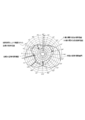
- FIG. 20 is a diagram for explaining the extended visual field range of the right eye.
- the outermost circle is the maximum visual field range of each eye (below, assuming that the visual field is not restricted at all by the face and head and / or the object worn on the face and head). Also called “virtual maximum field of view”).
- the lower right direction of FIG. 20 has the widest field of view, and the maximum field of view is widened in all directions based on this maximum viewing angle. As shown by the arrows in FIG.
- the normal visual field range and / or Information can be displayed in the range from the normal visual field range to the virtual maximum visual field range.
- the range from the normal visual field range to the virtual maximum visual field range is shown in a checkered pattern.
- the extended visual field range that particularly matches the virtual maximum visual field range is also referred to as the “maximum extended visual field range”.
- FIG. 22 shows the maximum extended visual field range when a wide display exceeding the maximum viewing angle of the user is made possible by irradiating the display light in a range wider than the virtual maximum visual field range of FIG. As shown by the arrows in FIG.
- the normal visual field range and / or Information can be displayed in the range from the normal visual field range to the extended virtual maximum visual field range.
- FIG. 23 is a diagram showing a state in which the visual field range of both eyes is extended to the virtual maximum visual field range, that is, a state in which the extended visual field range of both eyes matches the virtual maximum visual field range.
- the maximum extended visual field range (maximum virtual visual field range) of the right eye is shown by a solid line
- the maximum extended visual field range (maximum virtual visual field range) of the left eye is shown by a broken line.
- the field of view is recognized in the range that can be seen on a daily basis, it is not usually felt that the field of view is narrow.
- the visual field inside the left eye is 30 to 40 ° narrower than the visual field outside, the visual field does not feel narrow because the visual field information obtained by the right eye is interpolated in the brain.
- the visual field information of both eyes is interpolated in the brain. It is possible to recognize that the image is displayed in the right peripheral visual field (peripheral part of the visual field range) of the right eye.
- FIG. 24 is a diagram showing a state in which the left eye has a narrowed visual field, and the visual field range of the left eye shown by a small broken line is narrower than the normal visual field range shown by a large broken line.
- FIG. 25 is a diagram showing a state in which the visual field range of the right eye is expanded from the state of FIG. 24. Therefore, as shown in FIG. 25, light is emitted from the light irradiation system 100 to at least a part of the ambient light irradiation range 10 and the pupil side range 20 in the left side range (left eye side range) in the retina of the right eye.
- the visual field range of the left eye can be substantially expanded to be larger than the normal visual field range.
- the range from the light irradiation system 100 to the right side of the retina of the left eye is at least one of the ambient light irradiation range 10 and the pupil side range 20.
- the light irradiation system 100 is selectively selected from an ambient light irradiation range 10, a range 20 on the pupil side of the ambient light irradiation range 10 in the retina 1, and a range straddling the ambient light irradiation range 10 and the pupil side range 20. Can be illuminated with light.
- the display device 150 according to the second embodiment of the present technology will be described with reference to FIGS. 26 to 28.
- the light irradiation system 200 has an optical element 200a integrated into the eyeball at least during use, and light directed toward the optical element 200a. Includes an optical projection unit 200b for projecting.
- the optical element 200a is, for example, a contact lens type optical element (for example, a lens), has a function of bending an incident light ray by refraction or diffraction, and is attached to the eyeball EB so as to cover the cornea 5.
- 26 and 27 show an example in which the optical element 200a is attached to the left eye.
- the light projection unit 200b includes, for example, a light source and a collimating lens that makes the light from the light source parallel light.
- the projected light PL0 projected from the light projection unit 200b and incident on the central position of the optical element 200a passes through the optical element 200a, then passes through the cornea 5 and the pupil 4, and is used as the display light DL0 in the environment.
- the light irradiation range 10 is irradiated.
- the projected ray PL1 projected from the light projection unit 200b and incident on the uppermost position of the optical element 200a is largely refracted or diffracted downward by the optical element 200a, passes through the cornea 5 and the pupil 4, and is displayed.
- FIG. 26 for example, the projected light PL0 projected from the light projection unit 200b and incident on the central position of the optical element 200a passes through the optical element 200a, then passes through the cornea 5 and the pupil 4, and is used as the display light DL0 in the environment.
- the light irradiation range 10 is irradiated.
- the projected light ray PL2 projected from the light projection unit 200b and incident on the first position between the uppermost position and the central position of the optical element 200a is refracted or diffracted downward by the optical element 200a, and the cornea is formed. 5. It passes through the pupil 4 and is incident on the rear end 20V-1b of the lower pupil side range 20V-1 as the display light DL2.
- a projected light beam projected from the light projection unit 200b and incident on an arbitrary position between the uppermost position of the optical element 200a and the first position is refracted or diffracted downward by the optical element 200a. It passes through the cornea 5 and the pupil 4 and is incident on the lower pupil side range 20V-1 as display light.
- FIG. 26 for example, the projected light ray PL2 projected from the light projection unit 200b and incident on the first position between the uppermost position and the central position of the optical element 200a is refracted or diffracted downward by the optical element 200a, and the cornea is formed. 5. It passes through the pupil 4 and is incident on the rear end 20
- a projected light beam projected from the light projection unit 200b and incident on an arbitrary position between the first position and the center position of the optical element 200a is refracted or diffracted downward by the optical element 200a. It passes through the cornea 5 and the pupil 4 and is incident on the ambient light irradiation range 10 as display light.
- the projected ray PL4 projected from the light projection unit 200b and incident on the lowest position of the optical element 200a is largely refracted or diffracted upward by the optical element 200a, passes through the cornea 5 and the pupil 4, and passes through the cornea 5 and the pupil 4. As the display light DL4, it is incident on the front end 20V-2a of the upper pupil side range 20V-2.
- the projected light ray PL3 projected from the light projection unit 200b and incident on the second position between the lowermost position and the central position of the optical element 200a is refracted or diffracted upward by the optical element 200a.
- a projected light beam projected from the light projection unit 200b and incident on an arbitrary position between the uppermost position of the optical element 200a and the second position is refracted or diffracted upward by the optical element 200, and the cornea is formed. 5. It passes through the pupil 4 and is incident on the upper pupil side range 20V-2 as display light.
- a projected light beam projected from the light projection unit 200b and incident on an arbitrary position between the second position and the center position of the optical element 200a is refracted or diffracted upward by the optical element 200a and is reflected on the cornea. 5. It passes through the pupil 4 and is incident on the ambient light irradiation range 10 as display light.
- the projected ray PL0 projected from the light projection unit 200b and incident on the central position of the optical element 200a passes through the optical element 200a, then passes through the cornea 5 and the pupil 4, and is used as the display light DL0 in the environment.
- the light irradiation range 10 is irradiated.
- the projected ray PL5 projected from the light projection unit 200b and incident on the rightmost position of the optical element 200a is refracted or diffracted to the left by the optical element 200a, passes through the cornea 5 and the pupil 4, and passes through the cornea 5 and the pupil 4.
- the projected light ray PL6 projected from the light projection unit 200b and incident on the third position between the rightmost position and the center position of the optical element 200a is refracted or diffracted to the left by the optical element 200a.
- a projected light beam projected from the light projection unit 200b and incident on an arbitrary position between the rightmost position of the optical element 200a and the third position is refracted or diffracted to the left by the optical element 200a. Then, it passes through the cornea 5 and the pupil 4, and is incident on the left pupil side range 20H-1 as display light.
- FIG. 27 for example, the projected light ray PL6 projected from the light projection unit 200b and incident on the third position between the rightmost position and the center position of the optical element 200a is refracted or diffracted to the left by the optical element 200a.
- a projected light beam projected from the light projection unit 200b and incident on an arbitrary position between the third position and the center position of the optical element 200a is refracted or diffracted to the left by the optical element 200a. It passes through the cornea 5 and the pupil 4 and is incident on the ambient light irradiation range 10 as display light.
- the projected ray PL8 projected from the light projection unit 200b and incident on the leftmost position of the optical element 200a is largely refracted or diffracted to the right by the optical element 200a and passes through the cornea 5 and the pupil 4.
- the display light DL8 is incident on the front end 20H-2a of the right pupil side range 20H-2.
- the projected light ray PL7 projected from the light projection unit 200b and incident on the fourth position between the leftmost position and the center position of the optical element 200a is refracted or diffracted to the right by the optical element 200a.
- a projected light beam projected from the light projection unit 200b and incident on an arbitrary position between the leftmost position of the optical element 200a and the fourth position is refracted or diffracted to the right by the optical element 200a.
- a projected light beam projected from the light projection unit 200b and incident on an arbitrary position between the fourth position and the center position of the optical element 200a is refracted or diffracted to the right by the optical element 200a. It passes through the cornea 5 and the pupil 4 and is incident on the ambient light irradiation range 10 as display light.
- FIG. 28 is a block diagram showing the functions of the display system 2000 including the display device 150 according to the second embodiment.
- the display system 2000 uses the display device 50 shown in FIG. 18 except that the drive target of the drive unit 1000c is the light projection unit 200b (more specifically, the light source of the light projection unit 200b). It has the same configuration and function as the display system 1000 provided.
- the display device 150 according to the second embodiment described above also has substantially the same effect as the display device 50 according to the first embodiment.
- the display system 2000 including the display device 150 also has substantially the same effect as the display system 1000 including the display device 50.
- the display elements 300a (300a-1 to 300a-4) of the light irradiation system 300 (300-1 to 300-4) are attached to the crystalline lens 6. It is embedded.
- the display element 300a-1 of the first embodiment of the third embodiment is embedded in the inner center of the crystalline lens 6 in a substantially flat plate shape so as to face the pupil 4.
- the display light DL0 emitted from the pixel at the center of the display element 300a-1 of the first embodiment is incident on the ambient light irradiation range 10.
- the display light DL1 emitted from the rightmost pixel of the display element 300a-1 of the first embodiment is incident on the front end 20H-2a of the right pupil side range 20H-2.
- the first position between the rightmost position and the center position of the display element 300a-1 of the first embodiment is incident on the front end 20H-2a of the right pupil side range 20H-2.
- the display light DL2 emitted from the pixel at the position of is incident on the rear end 20H-2b of the right pupil side range 20H-2.
- the display light emitted from an arbitrary pixel located between the rightmost position of the display element 300a-1 of the first embodiment and the first position is in the right pupil side range 20H-2. Being incident.
- the display light emitted from an arbitrary pixel located between the first position and the center position of the display element 300a-1 of the first embodiment is incident on the ambient light irradiation range 10.
- the display light DL4 emitted from the leftmost pixel of the display element 300a-1 of the first embodiment is incident on the front end 20H-1a of the left pupil side range 20H-1.
- the display light DL3 emitted from the pixel at the second position between the leftmost position and the center position of the display element 300a-1 of the first embodiment is after the left pupil side range 20H-1. It is incident on the end 20H-1b.
- the display light emitted from an arbitrary pixel located between the leftmost position of the display element 300a-1 of the first embodiment and the second position is in the left pupil side range 20H-1. Being incident.
- the display light emitted from an arbitrary pixel located between the second position and the center position of the display element 300a-1 of the first embodiment is incident on the ambient light irradiation range 10.
- the display element 300a-2 of the third embodiment of the third embodiment is embedded in the inner center of the crystalline lens 6 in a substantially flat plate shape so as to face the pupil 4.
- the display light DL0 emitted from the pixel at the center of the display element 300a-2 of the second embodiment is incident on the ambient light irradiation range 10.
- the display light DL1 emitted from the rightmost pixel of the display element 300a-2 of the second embodiment is incident on the front end 20H-1a of the left pupil side range 20H-1.
- FIG. 30 Display device of the second embodiment of the third embodiment
- the display light DL2 emitted from the pixel at the first position between the rightmost position and the center position of the display element 300a-2 of the second embodiment is after the left pupil side range 20H-1. It is incident on the end 20H-1b.
- the display light emitted from an arbitrary pixel located between the rightmost position of the display element 300a-2 of the second embodiment and the first position is in the left pupil side range 20H-1. Being incident.
- the display light emitted from an arbitrary pixel located between the first position and the center position of the display element 300a-2 of the second embodiment is incident on the ambient light irradiation range 10.
- the display light DL4 emitted from the leftmost pixel of the display element 300a-2 of the second embodiment is incident on the front end 20H-2a of the right pupil side range 20H-2.
- the display light DL3 emitted from the pixel at the second position between the leftmost position and the center position of the display element 300a-2 of the second embodiment is after the right pupil side range 20H-2. It is incident on the end 20H-2b.
- the display light emitted from an arbitrary pixel located between the leftmost position of the display element 300a-2 of the second embodiment and the second position is in the right pupil side range 20H-2. Being incident.
- the display light emitted from an arbitrary pixel located between the second position and the center position of the display element 300a-2 of the second embodiment is incident on the ambient light irradiation range 10.
- the display element 300a-2 of the second embodiment emits a plurality of display lights so as to intersect each other inside the crystalline lens 6.
- the display element 300a-3 of the third embodiment of the third embodiment is located in the end portion of the crystalline lens 6 opposite to the pupil 4 side so as to face the pupil 4 and to face the pupil 4. It is embedded in a curved state so as to be convex on the side opposite to the pupil 4 side.
- the display light DL0 emitted from the pixel at the center of the display element 300a-3 of the third embodiment is incident on the ambient light irradiation range 10.
- the display light DL1 emitted from the rightmost pixel of the display element 300a-3 of the third embodiment is incident on the front end 20H-2a of the right pupil side range 20H-2.
- the display light DL2 emitted from the pixel at the first position between the rightmost position and the center position of the display element 300a-3 of the third embodiment is after the right pupil side range 20H-2. It is incident on the end 20H-2b.
- the display light emitted from an arbitrary pixel located between the rightmost position of the display element 300a-3 of the third embodiment and the first position is in the right pupil side range 20H-2. Being incident.
- the display light emitted from an arbitrary pixel located between the first position and the center position of the display element 300a-3 of the third embodiment is incident on the ambient light irradiation range 10.
- the display light DL4 emitted from the leftmost pixel of the display element 300a-3 of the third embodiment is incident on the front end 20H-1a of the left pupil side range 20H-1.
- the display light DL3 emitted from the pixel at the second position between the leftmost position and the center position of the display element 300a-3 of the third embodiment is after the left pupil side range 20H-1. It is incident on the end 20H-1b.
- the display light emitted from an arbitrary pixel located between the leftmost position of the display element 300a-3 of the third embodiment and the second position is in the left pupil side range 20H-1. Being incident.
- the display light emitted from an arbitrary pixel located between the second position and the center position of the display element 300a-3 of the third embodiment is incident on the ambient light irradiation range 10.
- the display element 300a-4 of the fourth embodiment of the third embodiment is embedded in the end portion of the crystalline lens 6 on the pupil 4 side in a curved state so as to be adjacent to the pupil 4. ..
- the display light DL0 emitted from the pixel at the center of the display element 300a-4 of the fourth embodiment is incident on the ambient light irradiation range 10.
- the display light DL1 emitted from the rightmost pixel of the display element 300a-4 of the fourth embodiment is incident on the front end 20H-1a of the left pupil side range 20H-1.
- the display light DL2 emitted from the pixel at the first position between the rightmost position and the center position of the display element 300a-4 of the fourth embodiment is after the left pupil side range 20H-1. It is incident on the end 20H-1b.
- the display light emitted from an arbitrary pixel located between the rightmost position of the display element 300a-4 of the fourth embodiment and the first position is in the left pupil side range 20H-1. Being incident.
- the display light emitted from an arbitrary pixel located between the first position and the center position of the display element 300a-4 of the fourth embodiment is incident on the ambient light irradiation range 10.
- the display light DL4 emitted from the leftmost pixel of the display element 300a-4 of the fourth embodiment is incident on the front end 20H-2a of the right pupil side range 20H-2.
- the display light DL3 emitted from the pixel at the second position between the leftmost position and the center position of the display element 300a-4 of the fourth embodiment is after the right pupil side range 20H-2. It is incident on the end 20H-2b.
- the display light emitted from an arbitrary pixel located between the leftmost position of the display element 300a-4 of the fourth embodiment and the second position is in the right pupil side range 20H-2. Being incident.
- the display light emitted from an arbitrary pixel located between the second position and the center position of the display element 300a-4 of the fourth embodiment is incident on the ambient light irradiation range 10.
- the display element 300a-4 of the fourth embodiment emits a plurality of display lights so as to intersect each other inside the crystalline lens 6.
- the display device 250 of the third embodiment described above also has the same effect as the display devices 50 and 150 of the first and second embodiments.
- Display devices 350 (display devices 350-1 to 350-6 of the first to sixth embodiments) according to the fourth embodiment of the present technology will be described with reference to FIGS. 33 to 38.
- the display device 350 will be described using only the cross-sectional view, but the same argument holds within the vertical cross section.
- the light irradiation system 400 (400-1 to 400-6) is the optical element 400a (400a-1 to 400a-6). It includes a light projection unit 200b that projects light onto the optical element 400a.
- the optical element 400a-1 of the display device 350-1 of the first embodiment of the fourth embodiment is embedded in the inner center of the crystalline lens 6 in a substantially flat state so as to face the pupil 4. It has been.
- the optical element 400a-1 has a refractive index distribution in which the refractive index that refracts incident light outward (in the direction from the central portion to the peripheral portion) increases from the central portion to the peripheral portion.
- the angle of diffraction of the light ray incident on the peripheral portion is larger than that of the light ray incident on the central portion of the optical element.
- the projected light ray PL0 projected from the light projection unit 200b, passing through the cornea 5 and the pupil 4 and incident on the central position of the optical element 400a-1 travels straight through the optical element 400a-1. It is incident on the ambient light irradiation range 10.
- the projected light ray PL1 projected from the light projection unit 200b, passing through the cornea 5 and the pupil 4 and incident on the rightmost position of the optical element 400a-1 is greatly increased to the right by the optical element 400a-1. It is refracted and incident on the front end 20H-2a of the right pupil side range 20H-2 as the display light DL1.
- FIG. 33 for example, the projected light ray PL0 projected from the light projection unit 200b, passing through the cornea 5 and the pupil 4 and incident on the central position of the optical element 400a-1, travels straight through the optical element 400a-1. It is incident on the ambient light irradiation range 10.
- the projected light ray PL2 projected from the light projection unit 200b passed through the cornea 5 and the pupil 4, and was incident on the first position between the rightmost position and the central position of the optical element 400a-1. It is refracted to the right by the optical element 400a-1 and incident on the rear end 20H-2b of the right pupil side range 20H-2 as the display light DL2.
- an arbitrary projected light beam projected from the light projection unit 200b passed through the cornea 5 and the pupil 4, and incident on a position between the rightmost position of the optical element 400a-1 and the first position. , It is refracted to the right by the optical element 400a-1 and incident on the right pupil side range 20H-2 as display light.
- FIG. 33 for example, the projected light ray PL2 projected from the light projection unit 200b, passed through the cornea 5 and the pupil 4, and was incident on the first position between the rightmost position and the central position of the optical element 400a-1. It is refracted to the right by the optical element 400a-1 and incident on the rear end 20H-2b of
- any projected light beam projected from the light projection unit 200b, passed through the cornea 5 and the pupil 4, and incident on the position between the first position and the center position of the optical element 400a-1 is It is refracted to the right by the optical element 400a-1 and incident on the ambient light irradiation range 10 as display light.
- the projected light ray PL4 projected from the light projection unit 200b, passing through the cornea 5 and the pupil 4 and incident on the leftmost position of the optical element 400a-1 is greatly increased to the left by the optical element 400a-1. It is refracted and incident on the front end 20H-1a of the left pupil side range 20H-1 as the display light DL4.
- the projected light ray PL3 projected from the light projection unit 200b passed through the cornea 5 and the pupil 4, and was incident on the second position between the leftmost position and the central position of the optical element 400a-1. It is refracted to the left by the optical element 400a-1 and incident on the rear end 20H-1b of the left pupil side range 20H-1 as display light DL3.
- an arbitrary projected light beam projected from the light projection unit 200b passed through the cornea 5 and the pupil 4, and incident on a position between the leftmost position of the optical element 400a-1 and the second position. , It is refracted to the left by the optical element 400a-1 and incident on the left pupil side range 20H-1 as display light.
- an arbitrary projected light beam projected from the light projection unit 200b, passed through the cornea 5 and the pupil 4, and incident on a position between the second position and the central position of the optical element 400a-1 is projected. It is refracted to the left by the optical element 400a-1 and incident on the ambient light irradiation range 10 as display light.
- the optical element 400a-2 of the second embodiment of the fourth embodiment is embedded in the inner center of the crystalline lens 6 in a substantially flat plate shape so as to face the pupil 4.
- the optical element 400a-2 has a refractive index distribution in which the refractive index increases so as to refract the incident light inward (in the direction from the peripheral portion to the central portion) from the central portion to the peripheral portion.
- the angle of diffracting the light ray incident on the peripheral portion is larger than that of the light ray incident on the central portion of the optical element.
- the projected light ray PL0 projected from the light projection unit 200b, passing through the cornea 5 and the pupil 4 and incident on the central position of the optical element 400a-2 travels straight through the optical element 400a-2. It is incident on the ambient light irradiation range 10.
- the projected light ray PL1 projected from the light projection unit 200b, passing through the cornea 5 and the pupil 4 and incident on the rightmost position of the optical element 400a-2 is greatly left by the optical element 400a-2. It is refracted and incident on the front end 20H-1a of the left pupil side range 20H-1 as the display light DL1.
- FIG. 34 for example, the projected light ray PL0 projected from the light projection unit 200b, passing through the cornea 5 and the pupil 4 and incident on the central position of the optical element 400a-2 travels straight through the optical element 400a-2. It is incident on the ambient light irradiation range 10.
- the projected light ray PL2 projected from the light projection unit 200b passed through the cornea 5 and the pupil 4, and was incident on the first position between the rightmost position and the central position of the optical element 400a-2. It is refracted to the left by the optical element 400a-1 and incident on the rear end 20H-1b of the left pupil side range 20H-1 as display light DL2.
- an arbitrary projected light beam projected from the light projection unit 200b passed through the cornea 5 and the pupil 4, and incident on a position between the rightmost position of the optical element 400a-2 and the first position. , It is refracted to the left by the optical element 400a-2 and incident on the left pupil side range 20H-1 as display light.
- FIG. 34 for example, the projected light ray PL2 projected from the light projection unit 200b, passed through the cornea 5 and the pupil 4, and was incident on the first position between the rightmost position and the central position of the optical element 400a-2. It is refracted to the left by the optical element 400a-1 and incident on the rear end 20H-1b of the
- any projected light beam projected from the light projection unit 200b, passed through the cornea 5 and the pupil 4, and incident on the position between the first position and the center position of the optical element 400a-2 is It is refracted to the left by the optical element 400a-2 and is incident on the ambient light irradiation range 10 as display light.
- the projected light ray PL4 projected from the light projection unit 200b, passing through the cornea 5 and the pupil 4 and incident on the leftmost position of the optical element 400a-2 is greatly increased to the right by the optical element 400a-2. It is refracted and incident on the front end 20H-2a of the right pupil side range 20H-2 as the display light DL4.
- an arbitrary projected light beam projected from the light projection unit 200b, passed through the cornea 5 and the pupil 4, and incident on a position between the second position and the central position of the optical element 400a-2 is It is refracted to the right by the optical element 400a-2 and is incident on the ambient light irradiation range 10 as display light.
- a plurality of projected rays projected from the light projection unit 200b are emitted from the optical element 400a-2 so as to intersect inside or near the optical element 400a-2.
- the optical element 400a-3 of the display device 350-3 of the third embodiment of the fourth embodiment is curved so as to be adjacent to the pupil 4 in the end portion of the crystalline lens 6 on the pupil 4 side. It is embedded in.
- the optical element 400a-3 is in a curved state as described above, and the refractive index decreases so as to refract the incident light outward (in the direction from the central portion to the peripheral portion) as it goes from the central portion to the peripheral portion. It has a rate distribution.
- the angle of diffraction of the light ray incident on the peripheral portion is larger than that of the light ray incident on the central portion of the optical element.
- the projected light ray PL0 projected from the light projection unit 200b, passing through the cornea 5 and the pupil 4 and incident on the central position of the optical element 400a-3 travels straight through the optical element 400a-3. It is incident on the ambient light irradiation range 10.
- the projected light ray PL1 projected from the light projection unit 200b, passing through the cornea 5 and the pupil 4 and incident on the rightmost position of the optical element 400a-3 is greatly increased to the right by the optical element 400a-3. It is refracted and incident on the front end 20H-2a of the right pupil side range 20H-2 as the display light DL1.
- FIG. 35 for example, the projected light ray PL0 projected from the light projection unit 200b, passing through the cornea 5 and the pupil 4 and incident on the central position of the optical element 400a-3 travels straight through the optical element 400a-3. It is incident on the ambient light irradiation range 10.
- the projected light ray PL2 projected from the light projection unit 200b passed through the cornea 5 and the pupil 4, and was incident on the first position between the rightmost position and the central position of the optical element 400a-3. It is refracted to the right by the optical element 400a-3 and is incident on the rear end 20H-2b of the right pupil side range 20H-2 as the display light DL2.
- an arbitrary projected light beam projected from the light projection unit 200b passed through the cornea 5 and the pupil 4, and incident on a position between the rightmost position of the optical element 400a-3 and the first position. , It is refracted to the right by the optical element 400a-3 and incident on the right pupil side range 20H-2 as display light.
- FIG. 35 for example, the projected light ray PL2 projected from the light projection unit 200b, passed through the cornea 5 and the pupil 4, and was incident on the first position between the rightmost position and the central position of the optical element 400a-3. It is refracted to the right by the optical element 400a-3 and is incident on the rear end 20H-2
- any projected light beam projected from the light projection unit 200b, passed through the cornea 5 and the pupil 4, and incident on the position between the first position and the center position of the optical element 400a-3 is It is refracted to the right by the optical element 400a-3 and is incident on the ambient light irradiation range 10 as display light.
- the projected light ray PL4 projected from the light projection unit 200b, passing through the cornea 5 and the pupil 4 and incident on the leftmost position of the optical element 400a-3 is greatly increased to the left by the optical element 400a-3. It is refracted and incident on the front end 20H-1a of the left pupil side range 20H-1 as the display light DL4.
- an arbitrary projected light beam projected from the light projection unit 200b, passed through the cornea 5 and the pupil 4, and incident on a position between the second position and the central position of the optical element 400a-3 is It is refracted to the left by the optical element 400a-3 and is incident on the ambient light irradiation range 10 as display light.
- the optical element 400a-4 of the display device 350-4 of the fourth embodiment of the fourth embodiment faces the pupil 4 in the end portion of the crystalline lens 6 opposite to the pupil 4 side. It is embedded in a curved state.
- the optical element 400a-4 has a refractive index whose refractive index decreases so as to refract the incident light outward (in the direction from the central portion to the peripheral portion) from the central portion to the peripheral portion. It has a rate distribution.
- the angle of diffraction of the light ray incident on the peripheral portion is larger than that of the light ray incident on the central portion of the optical element.
- the projected light ray PL0 projected from the light projection unit 200b, passing through the cornea 5 and the pupil 4 and incident on the central position of the optical element 400a-4 travels straight through the optical element 400a-4. It is incident on the ambient light irradiation range 10.
- the projected light ray PL1 projected from the light projection unit 200b, passing through the cornea 5 and the pupil 4 and incident on the rightmost position of the optical element 400a-4 is greatly increased to the right by the optical element 400a-4. It is refracted and incident on the front end 20H-2a of the right pupil side range 20H-2 as the display light DL1.
- FIG. 36 for example, the projected light ray PL0 projected from the light projection unit 200b, passing through the cornea 5 and the pupil 4 and incident on the central position of the optical element 400a-4 travels straight through the optical element 400a-4. It is incident on the ambient light irradiation range 10.
- the projected light ray PL2 projected from the light projection unit 200b passed through the cornea 5 and the pupil 4, and was incident on the first position between the rightmost position and the central position of the optical element 400a-4. It is refracted to the right by the optical element 400a-4 and incident on the rear end 20H-2b of the right pupil side range 20H-2 as the display light DL2.
- an arbitrary projected light beam projected from the light projection unit 200b passed through the cornea 5 and the pupil 4, and incident on a position between the rightmost position of the optical element 400a-4 and the first position. , It is refracted to the right by the optical element 400a-4 and incident on the right pupil side range 20H-2 as display light.
- FIG. 36 for example, the projected light ray PL2 projected from the light projection unit 200b, passed through the cornea 5 and the pupil 4, and was incident on the first position between the rightmost position and the central position of the optical element 400a-4. It is refracted to the right by the optical element 400a-4 and incident on the rear end 20H-2b of
- the projected light ray PL4 projected from the light projection unit 200b, passing through the cornea 5 and the pupil 4 and incident on the leftmost position of the optical element 400a-4 is enlarged to the left by the optical element 400a-3. It is refracted and incident on the front end 20H-1a of the left pupil side range 20H-1 as the display light DL4.
- an arbitrary projected ray projected from the light projection unit 200b passed through the cornea 5 and the pupil 4, and incident on a position between the leftmost position of the optical element 400a-4 and the second position. , It is refracted to the left by the optical element 400a-4 and incident on the left pupil side range 20H-1 as display light.
- an arbitrary projected light beam projected from the light projection unit 200b, passed through the cornea 5 and the pupil 4, and incident on a position between the second position and the central position of the optical element 400a-4 is It is refracted to the left by the optical element 400a-4 and incident on the ambient light irradiation range 10 as display light.
- the light irradiation system 400-5 of the display device 350-5 of the fifth embodiment of the fourth embodiment has a plurality of (for example, two) optical elements 400a-5-1 and 400a-5.
- the optical elements 400a-5-1 and 400a-5-2 of the fifth embodiment are embedded in the crystalline lens 6 so as to face each other. More specifically, the optical element 400a-5-1 is embedded in the end of the crystalline lens 6 on the pupil 4 side in a curved state so as to be adjacent to the pupil 4.
- the optical elements 400a-5-2 are embedded in the end of the crystalline lens 6 opposite to the pupil 4 side so as to face the pupil 4.
- the optical element 400a-5-1 has a high refractive index so as to refract the incident light inward (in the direction from the peripheral portion to the central portion) as it goes from the central portion to the peripheral portion in the curved state as described above. It has a refractive index distribution. Further, as another example, when an optical element that diffracts an incident light ray is used instead of the optical element 400a-5-1, the light ray that is incident on the peripheral portion is smaller than the light ray that is incident on the central portion of the optical element. Make the angle of diffraction inward large.
- the optical element 400a-5-2 has a low refractive index so as to refract the incident light outward (in the direction from the central portion to the peripheral portion) as it goes from the central portion to the peripheral portion in the curved state as described above. It has a refractive index distribution. Further, as another example, when an optical element that diffracts an incident light ray is used instead of the optical element 400a-5-2, the light ray that is incident on the peripheral portion is smaller than the light ray that is incident on the central portion of the optical element. The angle at which is diffracted outward is increased.
- the projected light ray PL0 projected from the light projection unit 200b, passing through the cornea 5 and the pupil 4 and incident on the central position of the optical element 400a-5-1 travels straight while the optical element 400a-5. 1.
- the optical elements 400a-5-2 are sequentially transmitted and incident on the ambient light irradiation range 10.
- the projected light PL1 projected from the light projection unit 200b, passing through the cornea 5 and the pupil 4 and incident on the rightmost position of the optical element 400a-5-1 is the optical element 400a-5-1. It is greatly refracted to the left and is incident on the leftmost position of the optical element 400a-5-2.
- the projected ray PL1 incident on the leftmost position is largely refracted to the left by the optical element 400a-5-2, and is incident on the front end 20H-1a of the left pupil side range 20H-1 as display light DL1.
- Ru the projected ray PL2 projected from the light projection unit 200b, passed through the cornea 5 and the pupil 4, and was incident on the first position between the rightmost position and the center position of the optical element 400a-5-1. Is refracted to the left by the optical element 400a-1, and is incident on a second position between the leftmost position and the center position of the optical element 400a-5-2.
- the projected ray PL2 incident on the second position is refracted to the left by the optical element 400a-5-2 and is incident on the rear end 20H-1b of the left pupil side range 20H-1 as the display light DL2.
- Ru for example, an arbitrary projection projected from the light projection unit 200b, passed through the cornea 5 and the pupil 4, and incident on a position between the rightmost position of the optical element 400a-5-1 and the first position.
- a light beam is incident on a position between the leftmost position of the optical element 400a-5-2 and the second position.
- the incident arbitrary projected light ray is refracted to the left by the optical element 400a-5-2 and is incident on the left pupil side range 20H-1 as display light.
- FIG. 37 for example, an arbitrary projection projected from the light projection unit 200b, passed through the cornea 5 and the pupil 4, and incident on a position between the rightmost position of the optical element 400a-5-1 and the first position.
- a light beam is incident on a position between the leftmost position of the optical element 400a-5-2
- the projected light PL4 projected from the light projection unit 200b, passing through the cornea 5 and the pupil 4 and incident on the leftmost position of the optical element 400a-5-1 is the optical element 400a-5-1. It is greatly refracted to the right and is incident on the rightmost position of the optical element 400a-5-2.
- the projected ray PL4 incident on the rightmost position is largely refracted to the right by the optical element 400a-5-2, and is incident on the front end 20H-2a of the right pupil side range 20H-2 as display light DL4. Ru.
- the projected ray PL3 projected from the light projection unit 200b passed through the cornea 5 and the pupil 4, and was incident on the third position between the leftmost position and the center position of the optical element 400a-5-1. Is refracted to the right by the optical element 400a-5-1 and incident on a fourth position between the rightmost position and the center position of the optical element 400a-5-2.
- the projected ray PL3 incident on the fourth position is refracted to the right by the optical element 400a-5-2 and is incident on the rear end 20H-2b of the right pupil side range 20H-2 as the display light DL3. Ru.
- FIG. 37 for example, an arbitrary projection projected from the light projection unit 200b, passed through the cornea 5 and the pupil 4, and incident on a position between the leftmost position of the optical element 400a-5-1 and the third position.
- a light beam is incident on a position between the rightmost position of the optical element 400a-5-2 and the fourth position.
- the incident arbitrary projected light ray is refracted to the right by the optical element 400a-5-2 and is incident on the right pupil side range 20H-2 as display light.
- FIG. 37 for example, an arbitrary projected light beam projected from the light projection unit 200b, passed through the cornea 5 and the pupil 4, and incident on a position between the third position and the center position of the optical element 400a-5-2.
- the incident arbitrary projected light beam is refracted to the right by the optical element 400a-5-2 and is incident on the ambient light irradiation range 10 as display light.
- the optical element 400a-6 of the display device 350-6 of the sixth embodiment of the fourth embodiment is curved so as to be adjacent to the pupil 4 in the end portion of the crystalline lens 6 on the pupil 4 side. It is embedded in.
- the optical element 400a-6 is in a curved state as described above, and the refractive index increases so as to refract the incident light inward (in the direction from the peripheral portion to the central portion) as it goes from the central portion to the peripheral portion. It has a rate distribution.
- the angle of diffracting the light ray incident on the peripheral portion is larger than that of the light ray incident on the central portion of the optical element.
- the projected light ray PL0 projected from the light projection unit 200b, passing through the cornea 5 and the pupil 4 and incident on the central position of the optical element 400a-6 travels straight through the optical element 400a-6. It is incident on the ambient light irradiation range 10.
- the projected light ray PL1 projected from the light projection unit 200b, passing through the cornea 5 and the pupil 4 and incident on the rightmost position of the optical element 400a-6 is large to the left at the optical element 400a-6. It is refracted and incident on the front end 20H-1a of the left pupil side range 20H-1 as the display light DL1.
- FIG. 38 for example, the projected light ray PL0 projected from the light projection unit 200b, passing through the cornea 5 and the pupil 4 and incident on the central position of the optical element 400a-6 travels straight through the optical element 400a-6. It is incident on the ambient light irradiation range 10.
- the projected ray PL2 projected from the light projection unit 200b passed through the cornea 5 and the pupil 4, and incident on the first position between the rightmost position and the center position of the optical element 400a-6. It is refracted to the left by the optical element 400a-6 and is incident on the rear end 20H-1b of the left pupil side range 20H-1 as display light DL2.
- an arbitrary projected light beam projected from the light projection unit 200b passed through the cornea 5 and the pupil 4, and incident on a position between the rightmost position of the optical element 400a-6 and the first position. , It is refracted to the left by the optical element 400a-6, and is incident on the left pupil side range 20H-1 as display light.
- FIG. 38 for example, the projected ray PL2 projected from the light projection unit 200b, passed through the cornea 5 and the pupil 4, and incident on the first position between the rightmost position of the optical element 400a-6 and the first position.
- any projected light beam projected from the light projection unit 200b, passed through the cornea 5 and the pupil 4, and incident on the position between the first position and the center position of the optical element 400a-6 is It is refracted to the left by the optical element 400a-6 and is incident on the ambient light irradiation range 10 as display light.
- the projected light ray PL4 projected from the light projection unit 200b, passing through the cornea 5 and the pupil 4 and incident on the leftmost position of the optical element 400a-6 is enlarged to the right by the optical element 400a-6. It is refracted and incident on the front end 20H-2a of the right pupil side range 20H-2 as the display light DL4.
- an arbitrary projected light beam projected from the light projection unit 200b passed through the cornea 5 and the pupil 4, and incident on a position between the leftmost position of the optical element 400a-6 and the second position. , It is refracted to the right by the optical element 400a-6, and is incident on the right pupil side range 20H-2 as display light.
- an arbitrary projected light beam projected from the light projection unit 200b, passed through the cornea 5 and the pupil 4, and incident on a position between the second position and the central position of the optical element 400a-6 is projected. It is refracted to the right by the optical element 400a-6 and is incident on the ambient light irradiation range 10 as display light.
- a plurality of projected rays projected from the light projection unit 200b are emitted from the optical element 400a-6 so as to intersect inside or near the optical element 400a-6 (for example, inside the crystalline lens 6). Will be done.
- the display device 350 of the fourth embodiment described above also has substantially the same effect as the display devices 50 and 150 of the first and second embodiments.
- the display device of the fifth embodiment of the present technology has the same configuration as any of the display devices of the first to fourth embodiments, except that the characteristics of the display element or the optical element are different.
- the display element or optical element of the display device according to the fifth embodiment (however, in the case of the optical element, the light projection unit is also included) is the ambient light irradiation range 10 and the range outside the ambient light irradiation range 10 (for example, the pupil side range). In the extended visual field range corresponding to the range including 20), the viewing angle characteristic that the visibility in the peripheral portion is lower than the visibility in the central portion is exhibited.
- the display element or optical element of the display device of the fifth embodiment is, for example, an element having high visibility in the central portion of the normal visual field range corresponding to the ambient light irradiation range 10 in the extended visual field range.
- the display element or optical element of the display device of the fifth embodiment functions as an element having high visibility in the normal visual field range corresponding to the ambient light irradiation range 10 in the extended visual field range, and the normal visual field range. In the outside range, it may function as an element whose visibility gradually decreases as it approaches the maximum extended visual field range.
- the display element or optical element of the display device of the fifth embodiment is, for example, a predetermined normal visual field range corresponding to the ambient light irradiation range 10 in the extended visual field range, and a predetermined position outside the normal visual field range and within the maximum extended visual field range. In the range, it may function as an element having high visibility, and in a range outside the predetermined range, it may function as an element whose visibility gradually decreases as it approaches the maximum extended visual field range.
- the central portion is displayed so as to be brighter or darker than the central portion with respect to the peripheral portion in the extended visual field range.
- An element that lowers the visibility of the peripheral portion is mentioned.
- the display element or optical element that exhibits the above-mentioned viewing angle characteristics for example, a single color is superimposed on the peripheral portion in the above-mentioned extended visual field range, or a pattern such as a texture is superimposed and displayed. Therefore, the element may be an element that makes the peripheral portion inconspicuous as compared with the central portion.
- the peripheral portion As a display element or an optical element that exhibits the above-mentioned viewing angle characteristics, for example, by reducing the intensity of ambient light incident on the peripheral portion in the normal visual field range, the peripheral portion is set to the central portion in the normal visual field range. It may be an element that makes it inconspicuous in comparison.
- an element having a characteristic that the aberration or haze differs depending on the incident angle of light can be mentioned.
- Such an optical element is, for example, an optical element (for example, a hologram element) having a transmission characteristic depending on a viewing angle.
- Such a display element is, for example, a display element having a liquid crystal display unit having a viewing angle characteristic and a light source.
- the display device of the fifth embodiment for example, it is possible to suppress the user from recognizing unnecessary information in the peripheral portion of the visual field and to concentrate the user's feelings on the necessary information in the central portion of the visual field.
- the present technology can also have the following configuration.
- (2) The ambient light irradiation range is determined by a part of the face around the retina that prevents the ambient light from reaching the retina and / or an object attached to the face or head (1).
- the light irradiation system can irradiate either the pupil side range with respect to the ambient light irradiation range in the retina, the ambient light irradiation range, or the range straddling the pupil side range.
- the light irradiation system is any one of the ambient light irradiation range, the pupil side range of the ambient light irradiation range in the retina, and the ambient light irradiation range and the range straddling the pupil side range.
- the display device according to any one of (1) to (4), wherein the light irradiation system emits light so that the light intersects in the vicinity of the pupil.
- the display element according to any one of (1) to (5), wherein the light irradiation system irradiates light in a range of the retina of one eye opposite to the other eye side.
- the light irradiation system includes at least a display element integrated with the eyeball during use.
- the display element exhibits a viewing angle characteristic in which the visibility of the peripheral portion is lower than the visibility of the central portion in the viewing range corresponding to a range wider than the ambient light irradiation range, (1) to (1).
- the display device according to any one of 7).
- the display device (9) The display device according to (7) or (8), wherein the display element is a contact lens type display element.
- the display device (10) The display device according to any one of claims (7) to (9), wherein the display element is an intraocular lens type display element.
- the display element includes a plurality of pixels arranged in two dimensions or three dimensions.
- the display element has a transmitting portion that transmits at least a part of light in a specific wavelength band and a shading portion that blocks the light.
- the transmissive portion is a gap between the pixels.
- the display device according to (12), wherein the light-shielding portion is a gap between the pixels.
- the transmissive portion is wiring arranged between the pixels.
- the display element according to (12), wherein the light-shielding portion is wiring arranged between the pixels.
- the transmissive portion is a wiring between a pixel group composed of at least two pixels.
- the light-shielding portion is wiring between pixel groups composed of at least two pixels.
- the display element has the plurality of pixels arranged in a staggered pattern.
- the display device according to any one of (7) to (19), wherein the display element is a self-luminous display element.
- the display element includes a liquid crystal display unit and a light source.
- a sensor for detecting information outside the normal visual field range which is information outside the normal visual field range corresponding to the ambient light irradiation range, is further provided, and the information outside the normal visual field range detected by the sensor corresponds to the wide range.
- the display device according to any one of (1) to (21), which is displayed in an extended field of view.
- the light irradiation system includes at least an optical element integrated with the eyeball during use and a light projection unit that projects light toward the optical element.
- the display device described in 1. The optical element exhibits a viewing angle characteristic in which the visibility of the peripheral portion is lower than the visibility of the central portion in a viewing range corresponding to a range wider than the ambient light irradiation range, according to (23).
- Display device. The display device according to (23) or (24), wherein the optical element is a contact lens type optical element.
- Retina Retina
- 4 Pupil
- 10 Ambient light irradiation range
- 20 Pupil side range (pupil side range)
- 50, 150, 250, 350 Display device
- 100, 200, 300, 400 Light irradiation system
- 100a, 300a display element
- 200a, 400a optical element
- 200b light projection unit.
Landscapes
- Physics & Mathematics (AREA)
- Health & Medical Sciences (AREA)
- Ophthalmology & Optometry (AREA)
- General Physics & Mathematics (AREA)
- Optics & Photonics (AREA)
- General Health & Medical Sciences (AREA)
- Nonlinear Science (AREA)
- Engineering & Computer Science (AREA)
- Cardiology (AREA)
- Vascular Medicine (AREA)
- Chemical & Material Sciences (AREA)
- Mathematical Physics (AREA)
- Microelectronics & Electronic Packaging (AREA)
- Oral & Maxillofacial Surgery (AREA)
- Transplantation (AREA)
- Biomedical Technology (AREA)
- Heart & Thoracic Surgery (AREA)
- Crystallography & Structural Chemistry (AREA)
- Life Sciences & Earth Sciences (AREA)
- Animal Behavior & Ethology (AREA)
- Public Health (AREA)
- Veterinary Medicine (AREA)
- Devices For Indicating Variable Information By Combining Individual Elements (AREA)
- Prostheses (AREA)
- Controls And Circuits For Display Device (AREA)
- Eyeglasses (AREA)
Priority Applications (4)
| Application Number | Priority Date | Filing Date | Title |
|---|---|---|---|
| JP2021562513A JP7586093B2 (ja) | 2019-12-02 | 2020-11-04 | 表示装置及び表示システム |
| US17/756,303 US12510771B2 (en) | 2019-12-02 | 2020-11-04 | Display device and display system |
| DE112020005995.2T DE112020005995T5 (de) | 2019-12-02 | 2020-11-04 | Anzeigevorrichtung und anzeigesystem |
| CN202080082549.3A CN114746798A (zh) | 2019-12-02 | 2020-11-04 | 显示装置和显示系统 |
Applications Claiming Priority (2)
| Application Number | Priority Date | Filing Date | Title |
|---|---|---|---|
| JP2019-218358 | 2019-12-02 | ||
| JP2019218358 | 2019-12-02 |
Publications (1)
| Publication Number | Publication Date |
|---|---|
| WO2021111792A1 true WO2021111792A1 (ja) | 2021-06-10 |
Family
ID=76222518
Family Applications (1)
| Application Number | Title | Priority Date | Filing Date |
|---|---|---|---|
| PCT/JP2020/041188 Ceased WO2021111792A1 (ja) | 2019-12-02 | 2020-11-04 | 表示装置及び表示システム |
Country Status (5)
| Country | Link |
|---|---|
| US (1) | US12510771B2 (https=) |
| JP (1) | JP7586093B2 (https=) |
| CN (1) | CN114746798A (https=) |
| DE (1) | DE112020005995T5 (https=) |
| WO (1) | WO2021111792A1 (https=) |
Cited By (1)
| Publication number | Priority date | Publication date | Assignee | Title |
|---|---|---|---|---|
| JPWO2024089869A1 (https=) * | 2022-10-28 | 2024-05-02 |
Citations (6)
| Publication number | Priority date | Publication date | Assignee | Title |
|---|---|---|---|---|
| JPH10301055A (ja) * | 1997-04-25 | 1998-11-13 | Sony Corp | 画像表示装置 |
| JP2015513688A (ja) * | 2012-02-06 | 2015-05-14 | バッテル メモリアル インスティテュートBattelle Memorial Institute | 画像生成システム及び画像生成方法 |
| WO2017213241A1 (ja) * | 2016-06-09 | 2017-12-14 | 株式会社Qdレーザ | 画像投影システム、画像投影装置、画像投影方法、画像投影プログラム及びサーバ装置 |
| JP2018538573A (ja) * | 2015-12-03 | 2018-12-27 | アイウェイ ビジョン リミテッドEyeWay Vision Ltd. | 画像投影システム |
| EP3435138A1 (en) * | 2017-07-28 | 2019-01-30 | Vestel Elektronik Sanayi ve Ticaret A.S. | Device for providing a panoramic view or a binocular view for a monocular eye |
| WO2019101994A1 (en) * | 2017-11-24 | 2019-05-31 | Optotune Ag | Near-eye display |
Family Cites Families (7)
| Publication number | Priority date | Publication date | Assignee | Title |
|---|---|---|---|---|
| KR20150015046A (ko) | 2006-10-10 | 2015-02-09 | 노파르티스 아게 | 광학적으로 조절되는 주변 부분을 갖는 렌즈 및 상기 렌즈의 설계 및 제조 방법 |
| US8057034B2 (en) | 2007-10-26 | 2011-11-15 | Brien Holden Vision Institute | Methods and apparatuses for enhancing peripheral vision |
| US8786675B2 (en) * | 2008-01-23 | 2014-07-22 | Michael F. Deering | Systems using eye mounted displays |
| US8982014B2 (en) | 2012-02-06 | 2015-03-17 | Battelle Memorial Institute | Image generation systems and image generation methods |
| US9993335B2 (en) * | 2014-01-08 | 2018-06-12 | Spy Eye, Llc | Variable resolution eye mounted displays |
| JP6255524B2 (ja) | 2016-06-09 | 2017-12-27 | 株式会社Qdレーザ | 画像投影システム、画像投影装置、画像投影方法、画像投影プログラム及びサーバ装置 |
| US10617567B2 (en) * | 2017-06-10 | 2020-04-14 | Manjinder Saini | Intraocular implant device |
-
2020
- 2020-11-04 WO PCT/JP2020/041188 patent/WO2021111792A1/ja not_active Ceased
- 2020-11-04 DE DE112020005995.2T patent/DE112020005995T5/de active Pending
- 2020-11-04 JP JP2021562513A patent/JP7586093B2/ja active Active
- 2020-11-04 US US17/756,303 patent/US12510771B2/en active Active
- 2020-11-04 CN CN202080082549.3A patent/CN114746798A/zh active Pending
Patent Citations (6)
| Publication number | Priority date | Publication date | Assignee | Title |
|---|---|---|---|---|
| JPH10301055A (ja) * | 1997-04-25 | 1998-11-13 | Sony Corp | 画像表示装置 |
| JP2015513688A (ja) * | 2012-02-06 | 2015-05-14 | バッテル メモリアル インスティテュートBattelle Memorial Institute | 画像生成システム及び画像生成方法 |
| JP2018538573A (ja) * | 2015-12-03 | 2018-12-27 | アイウェイ ビジョン リミテッドEyeWay Vision Ltd. | 画像投影システム |
| WO2017213241A1 (ja) * | 2016-06-09 | 2017-12-14 | 株式会社Qdレーザ | 画像投影システム、画像投影装置、画像投影方法、画像投影プログラム及びサーバ装置 |
| EP3435138A1 (en) * | 2017-07-28 | 2019-01-30 | Vestel Elektronik Sanayi ve Ticaret A.S. | Device for providing a panoramic view or a binocular view for a monocular eye |
| WO2019101994A1 (en) * | 2017-11-24 | 2019-05-31 | Optotune Ag | Near-eye display |
Cited By (2)
| Publication number | Priority date | Publication date | Assignee | Title |
|---|---|---|---|---|
| JPWO2024089869A1 (https=) * | 2022-10-28 | 2024-05-02 | ||
| WO2024089869A1 (ja) * | 2022-10-28 | 2024-05-02 | 株式会社センチュリーアークス | 投影装置および投影機能付きコンタクトレンズ |
Also Published As
| Publication number | Publication date |
|---|---|
| CN114746798A (zh) | 2022-07-12 |
| DE112020005995T5 (de) | 2022-10-13 |
| JPWO2021111792A1 (https=) | 2021-06-10 |
| US12510771B2 (en) | 2025-12-30 |
| US20220390765A1 (en) | 2022-12-08 |
| JP7586093B2 (ja) | 2024-11-19 |
Similar Documents
| Publication | Publication Date | Title |
|---|---|---|
| US12413698B2 (en) | Wearable image manipulation and control system with correction for vision defects and augmentation of vision and sensing | |
| US12055715B2 (en) | See-through near eye optical module | |
| AU2018239264B2 (en) | Eye-imaging apparatus using diffractive optical elements | |
| US20200257122A1 (en) | See-Through Near Eye Display Optical Dithering | |
| AU2023285715A1 (en) | Wearable image manipulation and control system with correction for vision defects and augmentation of vision and sensing | |
| KR20220115816A (ko) | 가상 및 증강 현실 시스템들 및 방법들 | |
| CN110770636B (zh) | 具有矫正视力缺陷、增强视力和感知能力的可穿戴图像处理和控制系统 | |
| US12174068B2 (en) | Augmented reality system and method for spectroscopic analysis | |
| EP3762764B1 (en) | See-through near eye optical module | |
| JP7786371B2 (ja) | 表示装置及び表示方法 | |
| JP2021516358A (ja) | 低遅延瞳孔トラッカーを伴うディスプレイシステム | |
| US20140091990A1 (en) | Head-mounted display system | |
| JP2022115982A (ja) | 偏光を送達し、グルコースレベルを決定するための拡張現実および仮想現実アイウェア、システム、および方法 | |
| US12572200B2 (en) | Augmented and virtual reality display systems for oculometric assessments | |
| CN116744839A (zh) | 用于头戴式显示器的目镜成像组合件 | |
| JP7586093B2 (ja) | 表示装置及び表示システム | |
| US12469331B2 (en) | Display apparatus and display system | |
| US20240393589A1 (en) | See-through near eye optical module | |
| CN116848457A (zh) | 眼睛配戴物 | |
| JP2012042838A (ja) | 眼鏡フレーム |
Legal Events
| Date | Code | Title | Description |
|---|---|---|---|
| 121 | Ep: the epo has been informed by wipo that ep was designated in this application |
Ref document number: 20895968 Country of ref document: EP Kind code of ref document: A1 |
|
| ENP | Entry into the national phase |
Ref document number: 2021562513 Country of ref document: JP Kind code of ref document: A |
|
| 122 | Ep: pct application non-entry in european phase |
Ref document number: 20895968 Country of ref document: EP Kind code of ref document: A1 |
|
| WWG | Wipo information: grant in national office |
Ref document number: 17756303 Country of ref document: US |