WO2021111684A1 - Photographing device and authentication device - Google Patents
Photographing device and authentication device Download PDFInfo
- Publication number
- WO2021111684A1 WO2021111684A1 PCT/JP2020/032464 JP2020032464W WO2021111684A1 WO 2021111684 A1 WO2021111684 A1 WO 2021111684A1 JP 2020032464 W JP2020032464 W JP 2020032464W WO 2021111684 A1 WO2021111684 A1 WO 2021111684A1
- Authority
- WO
- WIPO (PCT)
- Prior art keywords
- light
- fingers
- finger
- light source
- irradiation
- Prior art date
Links
- 238000003384 imaging method Methods 0.000 claims abstract description 69
- 238000012545 processing Methods 0.000 claims description 28
- 230000007423 decrease Effects 0.000 claims description 11
- 210000003811 finger Anatomy 0.000 description 341
- 210000004204 blood vessel Anatomy 0.000 description 31
- 238000000034 method Methods 0.000 description 31
- 230000003287 optical effect Effects 0.000 description 29
- 238000010586 diagram Methods 0.000 description 28
- 230000008859 change Effects 0.000 description 14
- 230000006870 function Effects 0.000 description 14
- 230000036544 posture Effects 0.000 description 13
- 230000008569 process Effects 0.000 description 12
- 238000009434 installation Methods 0.000 description 8
- 230000001678 irradiating effect Effects 0.000 description 8
- 238000004891 communication Methods 0.000 description 7
- 238000001514 detection method Methods 0.000 description 6
- 238000005286 illumination Methods 0.000 description 4
- 230000004397 blinking Effects 0.000 description 3
- 238000013075 data extraction Methods 0.000 description 3
- 210000004247 hand Anatomy 0.000 description 3
- 210000003813 thumb Anatomy 0.000 description 3
- 102000001554 Hemoglobins Human genes 0.000 description 2
- 108010054147 Hemoglobins Proteins 0.000 description 2
- 210000001015 abdomen Anatomy 0.000 description 2
- 238000010521 absorption reaction Methods 0.000 description 2
- NIXOWILDQLNWCW-UHFFFAOYSA-N acrylic acid group Chemical group C(C=C)(=O)O NIXOWILDQLNWCW-UHFFFAOYSA-N 0.000 description 2
- 238000002583 angiography Methods 0.000 description 2
- 238000006243 chemical reaction Methods 0.000 description 2
- 230000000694 effects Effects 0.000 description 2
- 238000005516 engineering process Methods 0.000 description 2
- 239000000284 extract Substances 0.000 description 2
- 239000011521 glass Substances 0.000 description 2
- 238000005259 measurement Methods 0.000 description 2
- 230000035945 sensitivity Effects 0.000 description 2
- 239000000758 substrate Substances 0.000 description 2
- 230000002238 attenuated effect Effects 0.000 description 1
- 239000003086 colorant Substances 0.000 description 1
- 230000000295 complement effect Effects 0.000 description 1
- 230000003247 decreasing effect Effects 0.000 description 1
- 230000007812 deficiency Effects 0.000 description 1
- 238000009792 diffusion process Methods 0.000 description 1
- 210000004932 little finger Anatomy 0.000 description 1
- 229910044991 metal oxide Inorganic materials 0.000 description 1
- 150000004706 metal oxides Chemical class 0.000 description 1
- 238000012986 modification Methods 0.000 description 1
- 230000004048 modification Effects 0.000 description 1
- 238000010606 normalization Methods 0.000 description 1
- 239000011295 pitch Substances 0.000 description 1
- 239000004065 semiconductor Substances 0.000 description 1
- 239000007787 solid Substances 0.000 description 1
- 230000007704 transition Effects 0.000 description 1
Images


Classifications
-
- G—PHYSICS
- G06—COMPUTING; CALCULATING OR COUNTING
- G06V—IMAGE OR VIDEO RECOGNITION OR UNDERSTANDING
- G06V40/00—Recognition of biometric, human-related or animal-related patterns in image or video data
- G06V40/10—Human or animal bodies, e.g. vehicle occupants or pedestrians; Body parts, e.g. hands
- G06V40/14—Vascular patterns
- G06V40/145—Sensors therefor
-
- A—HUMAN NECESSITIES
- A61—MEDICAL OR VETERINARY SCIENCE; HYGIENE
- A61B—DIAGNOSIS; SURGERY; IDENTIFICATION
- A61B5/00—Measuring for diagnostic purposes; Identification of persons
- A61B5/0059—Measuring for diagnostic purposes; Identification of persons using light, e.g. diagnosis by transillumination, diascopy, fluorescence
-
- A—HUMAN NECESSITIES
- A61—MEDICAL OR VETERINARY SCIENCE; HYGIENE
- A61B—DIAGNOSIS; SURGERY; IDENTIFICATION
- A61B5/00—Measuring for diagnostic purposes; Identification of persons
- A61B5/117—Identification of persons
- A61B5/1171—Identification of persons based on the shapes or appearances of their bodies or parts thereof
-
- G—PHYSICS
- G06—COMPUTING; CALCULATING OR COUNTING
- G06F—ELECTRIC DIGITAL DATA PROCESSING
- G06F21/00—Security arrangements for protecting computers, components thereof, programs or data against unauthorised activity
- G06F21/30—Authentication, i.e. establishing the identity or authorisation of security principals
- G06F21/31—User authentication
- G06F21/32—User authentication using biometric data, e.g. fingerprints, iris scans or voiceprints
-
- G—PHYSICS
- G06—COMPUTING; CALCULATING OR COUNTING
- G06F—ELECTRIC DIGITAL DATA PROCESSING
- G06F21/00—Security arrangements for protecting computers, components thereof, programs or data against unauthorised activity
- G06F21/30—Authentication, i.e. establishing the identity or authorisation of security principals
- G06F21/45—Structures or tools for the administration of authentication
-
- G—PHYSICS
- G06—COMPUTING; CALCULATING OR COUNTING
- G06V—IMAGE OR VIDEO RECOGNITION OR UNDERSTANDING
- G06V10/00—Arrangements for image or video recognition or understanding
- G06V10/10—Image acquisition
- G06V10/12—Details of acquisition arrangements; Constructional details thereof
- G06V10/14—Optical characteristics of the device performing the acquisition or on the illumination arrangements
- G06V10/141—Control of illumination
-
- G—PHYSICS
- G06—COMPUTING; CALCULATING OR COUNTING
- G06V—IMAGE OR VIDEO RECOGNITION OR UNDERSTANDING
- G06V10/00—Arrangements for image or video recognition or understanding
- G06V10/10—Image acquisition
- G06V10/12—Details of acquisition arrangements; Constructional details thereof
- G06V10/14—Optical characteristics of the device performing the acquisition or on the illumination arrangements
- G06V10/143—Sensing or illuminating at different wavelengths
-
- G—PHYSICS
- G06—COMPUTING; CALCULATING OR COUNTING
- G06V—IMAGE OR VIDEO RECOGNITION OR UNDERSTANDING
- G06V40/00—Recognition of biometric, human-related or animal-related patterns in image or video data
- G06V40/10—Human or animal bodies, e.g. vehicle occupants or pedestrians; Body parts, e.g. hands
- G06V40/12—Fingerprints or palmprints
- G06V40/13—Sensors therefor
- G06V40/1318—Sensors therefor using electro-optical elements or layers, e.g. electroluminescent sensing
-
- G—PHYSICS
- G06—COMPUTING; CALCULATING OR COUNTING
- G06V—IMAGE OR VIDEO RECOGNITION OR UNDERSTANDING
- G06V40/00—Recognition of biometric, human-related or animal-related patterns in image or video data
- G06V40/70—Multimodal biometrics, e.g. combining information from different biometric modalities
-
- H—ELECTRICITY
- H04—ELECTRIC COMMUNICATION TECHNIQUE
- H04N—PICTORIAL COMMUNICATION, e.g. TELEVISION
- H04N23/00—Cameras or camera modules comprising electronic image sensors; Control thereof
- H04N23/56—Cameras or camera modules comprising electronic image sensors; Control thereof provided with illuminating means
-
- H—ELECTRICITY
- H04—ELECTRIC COMMUNICATION TECHNIQUE
- H04N—PICTORIAL COMMUNICATION, e.g. TELEVISION
- H04N23/00—Cameras or camera modules comprising electronic image sensors; Control thereof
- H04N23/70—Circuitry for compensating brightness variation in the scene
- H04N23/74—Circuitry for compensating brightness variation in the scene by influencing the scene brightness using illuminating means
Definitions
- the present invention relates to a photographing device for photographing a living body and an authentication device for photographing and authenticating a living body.
- a biometric authentication technology using a biological image (blood vessel image) taken by utilizing the difference in absorption characteristics of near-infrared light between hemoglobin in a blood vessel and other biological tissues has been proposed.
- a blood vessel image can be obtained by irradiating a living body with near-infrared light having a high absorption rate of hemoglobin and imaging the transmitted or reflected light.
- different blood vessel patterns patterns exist for each individual, and high-precision authentication can be realized by clearly photographing these blood vessel patterns.
- the reflection type method is a method in which a light source and an imaging unit are arranged close to each other, irradiation light from the light source is applied to the pad of a finger, and the reflected light is imaged to acquire a blood vessel image.
- the biometric authentication device of Patent Document 1 below which is a reflection type, has a light source provided on the surface of a substrate and outputs light, and a plurality of diffraction gratings having different pitches and rotation directions are arranged to diffract the light to emit illumination light.
- the illumination area is provided with a diffraction optical element that irradiates the illumination area to be illuminated, and the illumination area is configured to be larger than the occupied area of the diffraction optical element and the light source on a plane parallel to the surface of the substrate.
- an authentication method using a blood vessel image obtained by simultaneously photographing not only one finger but also a plurality of fingers is effective.
- the reflective method it is possible to take blood vessel images of a plurality of fingers at the same time even when the living body is not in contact with the device, so that both high convenience and miniaturization of the device can be realized.
- the surface shape of the finger is three-dimensional and has many curved surfaces, in the reflective method, the amount of reflected light differs depending on the part of the finger, and sufficient brightness cannot be obtained in the area of the fingertip or the side surface of the finger (near the contour). .. Therefore, there is a problem that it is difficult to take a clear blood vessel image. In an unclear blood vessel image in which sufficient brightness is not obtained, the finger area cannot be detected accurately, and the authentication accuracy may decrease. Therefore, it is a problem to clearly capture the blood vessels of all the fingers to be captured, especially when attempting to capture blood vessel images of a plurality of fingers at the same time.
- An object of the present invention is to suppress a shortage of light intensity to a photographing target.
- the photographing apparatus which is one aspect of the invention disclosed in the present application is arranged at a position facing the plurality of presented fingers, and a plurality of imaging units for imaging the plurality of fingers and a plurality of imaging devices in the arrangement direction of the plurality of fingers.
- the imaging unit is characterized by having a plurality of light sources that irradiate the plurality of fingers with light from the outside of the facing region facing the plurality of fingers toward the inside of the facing region.
- the authentication device which is one aspect of the invention disclosed in the present application, is arranged at a position facing the plurality of presented fingers, and a plurality of imaging units for imaging the plurality of fingers and a plurality of the authentication devices in the arrangement direction of the plurality of fingers.
- An image processing unit that generates image data of the plurality of fingers, a first image data of the plurality of fingers generated by the image processing unit, and a second image of the plurality of fingers generated by the image processing unit. It is characterized by having an authentication unit that authenticates the plurality of fingers based on the data.
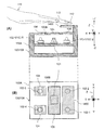
- FIG. 1 is an explanatory diagram showing a configuration example 1 of a photographing device and an authentication device according to the first embodiment.
- FIG. 2 is an explanatory diagram showing a configuration example 2 of the photographing device and the authentication device according to the first embodiment.
- FIG. 3 is a block diagram showing a block configuration example 1 of the photographing device and the authentication device according to the first embodiment.
- FIG. 4 is a block diagram showing a block configuration example 2 of the photographing device and the authentication device according to the first embodiment.
- FIG. 5 is an explanatory diagram showing an example 1 of irradiation from a light source.
- FIG. 6 is an explanatory diagram showing an irradiation example 2 from a light source.
- FIG. 7 is a flowchart showing an example of a finger image data registration processing procedure.
- FIG. 8 is a flowchart showing an example of a finger image data authentication processing procedure.
- FIG. 9 is a flowchart showing a detailed processing procedure example of the light source control (step S703) shown in FIGS. 7 and 8.
- FIG. 10 is a graph showing an example of the relationship between the amount of light emitted from the light source and the brightness of the finger region.
- FIG. 11 is an explanatory diagram showing a change in the position of the hand with respect to the photographing device and the authentication device.
- FIG. 12 is an explanatory diagram showing an example 1 of adjusting the amount of light according to the change in the posture of the hand.
- FIG. 13 is an explanatory diagram showing an example 2 of adjusting the amount of light according to the change in the posture of the hand.
- FIG. 14 is an explanatory diagram showing a configuration example 1 of the photographing device and the authentication device according to the second embodiment.
- FIG. 15 is an explanatory diagram showing an example of light amount control according to a change in the posture of a finger in the configuration example 1 of the photographing device and the authentication device according to the second embodiment.
- FIG. 16 is an explanatory diagram showing a configuration example 2 of the photographing device and the authentication device according to the second embodiment.
- FIG. 17 is an explanatory diagram showing a configuration example 3 of the photographing device and the authentication device according to the second embodiment.
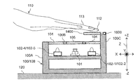
- FIG. 18 is an explanatory diagram showing a configuration example of the photographing device and the authentication device according to the third embodiment.
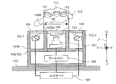
- FIG. 1 is an explanatory diagram showing a configuration example 1 of a photographing device and an authentication device according to the first embodiment.
- the photographing device 100 photographs the finger of the hand 110 held above the upper surface plate portion 100B of the housing 100A as a subject.
- the index finger 111, the middle finger 112, and the ring finger 113 are used as subjects (imaging targets).
- the fingers 111 to 113 to be the subject may include two or more of the ten fingers of both hands 110.
- the surface on the back side of the hands 110 of the fingers 111 to 113 is referred to as the front surface of the fingers 111 to 113, and the surface on the palm side of the hands 110 of the fingers 111 to 113 is referred to as the back surface of the fingers 111 to 113.
- the photographing apparatus 100 includes a housing 100A, an imaging unit 101, a light source 102, and a data memory 106.
- the device in which the controller 107 is connected to the photographing device 100 is the authentication device 108.
- the housing 100A is attached or placed on the installation surface 120 (hereinafter, collectively referred to as "installation").
- the installation surface 120 may be a surface of a table parallel to the ground such as the ground, a ceiling surface or a desk, or a surface perpendicular to the ground such as a wall.
- the axis orthogonal to the installation surface 120 is the Z axis
- the direction away from the installation surface 120 on the Z axis is the + Z direction
- the direction close to the installation surface 120 is the ⁇ Z direction.
- the installation surface 120 is parallel to the XY plane.
- the XY plane is a plane stretched by the X-axis and the Y-axis. As shown in FIG.
- the photographing device 100 and the authentication device 108 are installed so that the hand 110 is held over the top plate portion 100B.
- the X-axis is the longitudinal direction of the finger when the hand 110 is held over.
- the Y-axis is the arrangement direction of the fingers 111 to 113.
- the housing 100A includes an imaging unit 101 and a plurality of light sources 102 (light sources 102-1 and 102-2 in FIG. 1). When the light sources 102-1 and 102-2 are not distinguished, they are simply referred to as the light source 102. Further, a first optical filter 103 is provided between the image pickup unit 101 and the upper surface plate portion 100B of the housing 100A. The imaging unit 101 receives the subject light that has passed through the first optical filter 103. The subject light is light (reflected light) obtained by reflecting the irradiation light from the light source 102 on the subject.
- the image pickup unit 101 and the top plate portion 100B of the housing 100A face the presented hand 110.
- the surface facing the fingers 111 to 113 is referred to as the facing surface 100Ba.
- the region in the + Z direction from the facing surface 100Ba is the facing region 130 in which the presented fingers 111 to 113 face the imaging unit 101 and the facing surface 100Ba.
- the width of the facing surface 100Ba and the facing region 130 in the X-axis direction is, for example, a width including the length from the fingertip to the finger base of the fingers 111 to 113.
- a translucent plate 105 is provided to transmit the light reflected by the living body such as the fingers 111 to 113 of the irradiation light of the light source 102.
- the translucent plate 105 is made of a transparent member such as acrylic or glass. Further, a film that allows only light having a specific wavelength to pass through may be attached to the light transmitting plate 105. As a result, the inside of the photographing apparatus 100 can be made difficult to see from the outside.
- a second optical filter 104 is provided in the region of the upper surface plate portion 100B existing in the + Z direction from the light source 102.
- the light that has passed through the second optical filter 104 from the light source 102 is applied to the subject.
- the second optical filter 104 may be a light diffusion filter.
- the second optical filter 104 may be a polarizing filter. This makes it possible to reduce the specular reflection component on the skin surface among the light components reflected by irradiating the living body such as the fingers 111 to 113. Therefore, the imaging device 100 can capture a blood vessel image of a living body more clearly. Further, the second optical filter 104 may be a band filter that transmits only a specific wavelength of the irradiation light from the light source 102. As a result, it is possible to prevent the imaging unit 101 from receiving excess ambient light.
- the image pickup unit 101 is composed of, for example, an image pickup element such as a CMOS (Complementary Metal Oxide Semiconductor) image sensor or a CCD (Charge Coupled Device) image sensor.
- CMOS Complementary Metal Oxide Semiconductor
- CCD Charge Coupled Device
- the imaging unit 101 receives the light incident from the outside of the housing 100A through the light transmitting plate 105 of the upper surface plate portion 100B and the first optical filter 103 on the imaging surface and performs photoelectric conversion.
- the imaging unit 101 is connected to the data memory 106, and stores the photoelectrically converted image data in the data memory 106.
- the image data may be image data indicating a finger blood vessel (finger blood vessel image data) or image data indicating a fingerprint (fingerprint image data). Finger blood vessel image data and fingerprint image data are collectively referred to as finger image data.
- the data memory 106 is connected to the controller 107.
- the fingerprint is at least a pattern on the fingertip (pad of the finger), and may include a pattern on the back surface of the finger from the fingertip to the base of the finger.
- the light source 102 irradiates the subject existing in the + Z direction from the top plate portion 100B via the second optical filter 104.
- the irradiation light from the light source 102 is, for example, near-infrared light.
- the irradiation light from the light source 102 is, for example, visible light (for example, blue or green).
- the light source 102 is provided at a position sandwiching the image pickup unit 101. That is, the light sources 102 are arranged in the Y-axis direction.
- the light source 102 is arranged at a position between the fingertip and the finger base in the X-axis direction. In this way, each light source 102 irradiates the fingers 111 to 113 from the outside of the facing region 130 toward the inside of the facing region 130.
- the spread of the irradiation light from the light source 102 is called a light beam.
- the light beam is in the irradiation range of the finger 111 to 113 which is the subject.
- the light source 102 is arranged at a position where its light beam includes the fingers 111 to 113.
- the central axis of the optical beam is called the optical axis.
- the optical axis is the irradiation direction of light.
- the optical axis is not parallel to the Z axis, but is inclined from the Z axis (+ Z direction) toward the imaging unit 101 by a predetermined angle.
- the thumb side side surface of the index finger 111 and the little finger side side surface of the ring finger 113 are irradiated with a sufficient amount of light, but the middle finger 112, the middle finger side surface of the index finger 111 and the middle finger of the ring finger 113 are irradiated.
- the amount of light on the side surface is insufficient. Therefore, by inclining the irradiation direction toward the imaging unit 101 by a predetermined angle, each of the index finger 111, the middle finger 112, and the ring finger 113 is irradiated with a sufficient amount of light, and any of the index finger 111, the middle finger 112, and the ring finger 113 is irradiated. It is possible to suppress the lack of light on the side surface of the finger.
- the light source 102 is connected to the controller 107 outside the housing 100A.
- the controller 107 controls the amount of light emitted from the light source 102.
- the controller 107 detects the positions of the fingers 111 to 113, and extracts the features of the blood vessels and fingerprints in the fingers 111 to 113 from the finger image data.
- the controller 107 may authenticate a plurality of finger image data stored in the data memory 106. Specifically, for example, the controller 107 acquires two finger image data from the data memory 106, and the index finger 111, the middle finger 112, and the ring finger 113 of the two finger image data are the same from the characteristics of the blood vessels of the fingers and the characteristics of the fingerprint. It authenticates whether the person's index finger 111, middle finger 112, and ring finger 113.
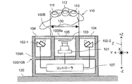
- FIG. 2 is an explanatory diagram showing a configuration example 2 of the photographing device 100 and the authentication device 108 according to the first embodiment.
- the photographing device 100 and the authentication device 108 shown in FIG. 2 are examples in which the controller 107 shown in FIG. 1 is mounted inside the housing 100A. If the controller 107 does not have an authentication function, it is the photographing device 100, and if the controller 107 has an authentication function, it is the authentication device 108.
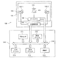
- FIG. 3 is a block diagram showing a block configuration example 1 of the photographing device 100 and the authentication device 108 according to the first embodiment.
- the photographing device 100 has a light source control unit 300.
- the light source control unit 300 controls the amount of irradiation light from the light source 102.
- the light source control unit 300 is included in the controller 107 shown in FIGS. 1 and 2.
- the computer 310 includes an authentication function.
- the computer 310 is included in the controller 107 shown in FIGS. 1 and 2.
- the computer 310 includes a processor 311, a storage device 312, an input device 313, an output device 314, and a communication interface (communication IF) 315.
- the processor 311, the storage device 312, the input device 313, the output device 314, and the communication IF 315 are connected by the bus 316.
- the processor 311 controls the computer 310.
- the storage device 312 serves as a work area for the processor 311. Further, the storage device 312 is a non-temporary or temporary recording medium for storing various programs and data. Examples of the storage device 312 include a ROM (Read Only Memory), a RAM (Random Access Memory), an HDD (Hard Disk Drive), and a flash memory.
- the input device 313 inputs data.
- the input device 313 includes, for example, a keyboard, a mouse, a touch panel, a numeric keypad, and a scanner.
- the output device 314 outputs data.
- Output devices 314 include, for example, displays, printers, and speakers.
- the communication IF 315 connects to the network and transmits / receives data.
- Examples of the program stored in the storage device 312 described above include an image processing program, a light source control program, and an authentication program.
- the image processing program is a program that causes the processor 311 to generate image data based on an output signal from the imaging unit 101.
- the light source control program is a program that causes the processor 311 to increase or decrease the amount of light emitted from the light source 102.
- the authentication program is a program that causes the processor 311 to authenticate the identity of the two finger image data stored in the storage device 312.
- the photographing device 100 including the light source control unit 300 is the photographing device 100 shown in FIG. 1
- the photographing device 100 including the light source control unit 300 is the photographing device 100 shown in FIG.
- the authentication device 108 having each function of image processing, light source control, and authentication includes a light source control unit 300 and a computer 310, and corresponds to the authentication device 108 of FIGS. 1 and 2.
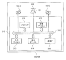
- FIG. 4 is a block diagram showing a block configuration example 2 of the photographing device 100 and the authentication device 108 according to the first embodiment.
- the photographing device 100 and the authentication device 108 shown in FIG. 4 include a computer 310.
- the data memory 106 is realized by the storage device 312.
- the light source control unit 300 is realized by causing the processor 311 to execute the program stored in the storage device 312.
- the authentication function is realized by causing the processor 311 to execute the program stored in the storage device 312. If the computer 310 does not have an authentication function, it is the photographing device 100, and if the computer 310 has an authentication function, it is the authentication device 108.
- At least one of the light sources 102 shown in FIGS. 1 to 4 may be a visible light source.
- the controller 107 may control the visible light source so as to emit light of different colors at the time of detecting the hand 110 during standby, at the time of authentication processing, at the time of successful authentication, and at the time of authentication failure. As a result, the user can visually recognize the authentication status.
- the computer 310 accepts the user ID and the password by the input device 313, and wirelessly receives the user ID and the password from the IC chip or the communication terminal possessed by the user by the communication IF 315. Therefore, the user ID and the personal identification number may be registered in the storage device 312 in association with the finger image data of the user.
- the computer 310 associates the user ID and the password and the finger image data stored in the storage device 312 with the user ID and the password by acquiring the user ID and the password and the finger image data from the input device 313 or the communication IF 315 as described above.
- the finger image data to be used may be specified and both finger image data may be authenticated (so-called one-to-one authentication).
- the computer 310 may specify finger image data that matches the finger image data input this time from the finger image data group stored in the storage device 312 (so-called 1-to-N authentication).
- the irradiation light from the light source 102 may include light having a plurality of different wavelengths.
- the image pickup unit 101 is composed of a plurality of sensors having different wavelength sensitivity characteristics such as a color camera, the image pickup unit 101 simultaneously irradiates a plurality of different wavelength lights from the light source 102, and the fingers 111 to 111 to The fingers 111 to 113 are photographed by the reflected light from 113.
- the controller 107 can efficiently separate the finger region irradiated with light from the light source 102 and the background region not illuminated by the light source 102 by utilizing the difference in the wavelength sensitivity characteristics of each sensor.
- the light source 102 may irradiate not only near-infrared light for angiography but also light having a wavelength suitable for photographing fingerprints, which is an uneven structure on the surface of the skin.
- the computer 310 can perform multi-modal authentication using the blood vessels of the fingers 111 to 113 and the fingerprint.
- each of the second optical filters 104 may be a band filter that transmits only each wavelength.
- the second optical filter 104 may be a band filter that transmits one wide wavelength band including a plurality of wavelengths.
- ⁇ Example of irradiation from the light source 102> When a single light source is arranged directly under the plurality of fingers 111 to 113, that is, in the vicinity of the imaging unit 101, the vicinity of the center of the abdomen of the fingers 111 to 113 is regarded as a horizontal plane and is exposed to strong irradiation light. As a result, the image pickup unit 101 can receive the reflected light having sufficient brightness.
- the curved surface shape of the fingers 111 to 113 makes it difficult for the irradiation light to hit the vicinity of the contour of the other fingers and the vicinity of the fingertips far from the pad of the fingers 111 to 113. In such an arrangement of a single light source, the imaging unit 101 cannot receive the reflected light having sufficient brightness, so that it becomes dark, and the controller 107 cannot generate finger image data that becomes a clear finger image.
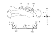
- FIG. 5 is an explanatory diagram showing an irradiation example 1 from the light source 102.
- the light source 102 is arranged in advance so as to be located further outside the outer finger along the arrangement direction Y of the fingers 111 to 113.
- the optical axis I is a direction inclined by a predetermined angle ⁇ from the Z axis in the direction in which the other light source 102 exists around the X axis.
- the light source 102-1 irradiates the back surface and thumb side side surface 111A of the index finger 111, the back surface and index finger side side surface 112A of the middle finger 112, and the back surface and middle finger side side surface 113A of the ring finger 113 (light beam). Included in 500).
- the light source 102-2 irradiates the back surface and the middle finger side side surface 113B of the ring finger 113, the back surface and the index finger side side surface 112B of the middle finger 112, and the back surface and the thumb side side surface 111B of the index finger 111.
- each light source 102 can irradiate sufficient light near the contour of the finger far from the position of the light source 102.
- a lens may be used in which the amount of irradiation light becomes stronger as the distance from the irradiation position increases.
- the light source 102 can irradiate a sufficient amount of light near the contour of the finger far from the irradiation position.
- the irradiation light from the light source 102 strongly hits not only the vicinity of the center of the abdomen of the fingers 111 to 113 but also the vicinity of the contours of the fingers 111 to 113, and the imaging unit 101 is sufficient in the entire area of the finger region. Receives reflected light of brightness. As a result, the controller 107 can generate finger image data that becomes a clear finger image.
- a plurality of light sources 102 are irradiated at the same time, there is a region where the irradiation lights overlap each other.
- the arrangement of the light source 102 is determined so that the entire area of all the fingers has uniform brightness, and the controller 107 adjusts the intensity of the irradiation light, taking into consideration that the irradiation light overlaps and strengthens each other. Will be done. Specifically, for example, in each light source 102, the distance to the nearest finger is the same or the difference between these distances is within the tolerance range, and the distance to the farthest finger is the same or the difference between these distances is the tolerance. Arranged so as to be within the range.
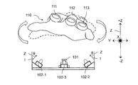
- FIG. 6 is an explanatory diagram showing an irradiation example 2 from the light source 102.
- FIG. 6 is an example in which the distance measuring sensor 600 is provided in the vicinity of the imaging unit 101 in the configuration of FIG.
- the distance measuring sensor 600 is installed at a position in the housing 100A such that the distance from the installation surface 120 in the + Z direction is the same.
- the distance measuring sensor 600 detects the distance D between the fingers 111 and 113, that is, the distance D between the fingers 111 and 113 and the imaging unit 101.
- the distance measuring sensor 600 has a distance D from the fingers 111 to 113 due to a time difference between irradiating the fingers 111 to 113 with infrared light and receiving the reflected light from the fingers 111 to 113. Is detected.
- the distance measuring sensor 600 may detect the distance D between the fingers 111 and 113 based on the capacitance between the fingers 111 and 113.
- the controller 107 controls the amount of light from the light source 102 to increase or decrease according to the distance D. For example, the controller 107 decreases the irradiation light amount of the light source 102 as the distance D becomes shorter, and increases the irradiation light amount of the light source 102 as the distance D becomes longer.
- FIG. 7 is a flowchart showing an example of a finger image data registration processing procedure.
- the executing subject is the authentication device 108 as an example, but the photographing device 100 may also be used.
- the authentication device 108 executes the detection of the fingers 111 to 113 (step S701).
- the imaging unit 101 receives the reflected light from the ambient light of the fingers 111 to 113 (or the irradiation light of a predetermined amount of light from the light source 102) and performs photoelectric conversion to generate binary image data.
- the controller 107 separates the main subject and the background of the binary image data, and determines whether or not the shape of the main subject is the fingers 111 to 113.
- the authentication device 108 may take a picture by blinking the light source 102, and may execute the detection of the fingers 111 to 113 by utilizing the change in the brightness of the taken image data. Further, when the distance measuring sensor 600 is built in, the authentication device 108 may detect the presence of the hand 110 approaching a predetermined position or within a certain range by using the distance measuring sensor 600. Further, the blinking of the light source 102 and the distance measurement by the distance measurement sensor 600 may be used together.
- step S703 is a process of controlling the amount of light of the light source 102. Details of the light source control (step S703) will be described later with reference to FIG.
- the imaging unit 101 receives the reflected light from the fingers 111 to 113 and generates finger image data by image processing (step S704).
- the generated finger image data is stored in the data memory 106 or the storage device 312.
- the authentication device 108 detects the finger region from the generated finger image data by image processing (step S705), and normalizes the finger image data by image processing (step S706). Normalization is a process of correcting the enlargement ratio and distortion due to finger position fluctuation and posture fluctuation based on the detected finger position. Then, the authentication device 108 extracts the feature data of the finger blood vessel or the fingerprint from the normalized finger image data by image processing (step S707). The authentication device 108 stores the feature data in the data memory 106 or the storage device 312 (step S708). Although the authentication device 108 stores the feature data in step S708, the finger image data may be stored in the data memory 106 or the storage device 312 without executing the feature data extraction (step S707).
- FIG. 8 is a flowchart showing an example of a finger image data authentication processing procedure.
- the executing subject is the authentication device 108 as an example, but the photographing device 100 may also be used.
- steps S808 to S811 are executed by the controller 107 or the computer 310 outside the photographing device 100.
- steps S701 to S707 are processes for the finger to be collated, the description thereof will be omitted because they are the same processes as those in FIG. 7.
- the feature data extraction is also executed for the finger image data of the comparison target to be compared with the collation target in step S707. ..
- the authentication device 108 After executing step S707, the authentication device 108 reads the registered feature data of the comparison target from the data memory 106 or the storage device 312 and collates it with the feature data of the collation target (step S808). Specifically, for example, the authentication device 108 calculates the collation score based on the identity of the position of the feature data and the identity of the feature.
- the identity of the position is, for example, the existence or nonexistence of the feature data to be compared within the same range as the position of the feature data to be collated or within the permissible range.
- the feature identity means, for example, that the shape of the blood vessel or fingerprint indicated by each feature data is the same or the difference in shape is acceptable between the feature data of the collation target having the same position and the feature data of the comparison target. To be within.
- the more feature data satisfying the position identity and feature identity of the feature data the higher the collation score.
- the authentication device 108 determines whether or not the collation score is larger than the threshold value TH (step S809).
- the authentication device 108 determines whether or not the time-out has occurred (step S810). If the time-out time has not elapsed (step S810: No), the process returns to step S703. On the other hand, when the timeout time has elapsed (step S810: Yes), the authentication process ends. Further, in step S809, when the collation score is larger than the threshold value TH (step S809: Yes), the authentication device 108 executes post-authentication processing (step S811), and the authentication process ends.
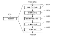
- FIG. 9 is a flowchart showing a detailed processing procedure example of the light source control (step S703) shown in FIGS. 7 and 8.
- the authentication device 108 acquires the image data used in the detection of the fingers 111 to 113 (step S901), and identifies each region of the plurality of fingers 111 to 113 (step S902).
- the authentication device 108 calculates the brightness of the specified finger region from the brightness information of the finger image data acquired in step S901.
- the authentication device 108 determines the light amount value of the light source 102 so that the finger region has an appropriate brightness based on the brightness of the finger region calculated in step S903 (step S904).
- the authentication device 108 turns on the light source 102 with the light amount value determined in step S904 (step S905), and proceeds to step S704.
- the brightness of the finger region calculated in step S903 may be, for example, the average brightness value of the finger region in the finger image data.
- the average brightness value may be calculated individually for each of the detected fingers 111 to 113, or may be the average of the brightness values of all the detected fingers 111 to 113. Further, as the finger region for calculating the average brightness value, not only the entire region of the fingers 111 to 113 can be used, but also a local region such as an intermediate position between the fingertip and the finger base can be used.
- the authentication device 108 when determining the light amount value in step S904, the authentication device 108 first sets an appropriate brightness (for example, average brightness) of the finger region in the image data as a specific target value in advance. Then, the authentication device 108 adjusts the irradiation light amount so that the brightness calculated in step S903 becomes the brightness of the target value, so that even if the distance D (height) from the fingers 111 to 113 fluctuates, the light source 102 can irradiate the fingers 111 to 113 with light of uniform intensity.
- an appropriate brightness for example, average brightness
- the authentication device 108 sets the authentication device 108. Increase the light intensity value by one step.
- the authentication device 108 reduces the light intensity value by one step.
- Another method for determining the light intensity value is to use the correlation between the light intensity value of the irradiation light from the light source 102 and the brightness of the finger region.
- the authentication device 108 (controller 107) irradiates the light source 102 with a light amount value corresponding to the target value of the finger area brightness based on the value of a function representing the relationship between the light amount value and the finger area brightness. Control.
- FIG. 10 is a graph showing an example of the relationship between the amount of irradiation light of the light source 102 and the brightness of the finger region.
- the horizontal axis of the graph 1000 is the brightness of the finger region (for example, the average brightness), and the vertical axis is the amount of light from the light source.
- the relationship between the brightness x of the finger region and the light amount value y emitted by the light source can be linearly approximated
- the relationship between the brightness x and the light amount value y can be expressed by the following equation (1).
- ⁇ and ⁇ in the above equation (1) are parameters that change depending on the environment and the difference in the finger, and are calculated every time the brightness x of the finger region is calculated.
- the authentication device 108 substitutes the brightness x'of the target finger region into the above equation (1) to obtain the light quantity value y'corresponding to the brightness x'.
- the light source 102 is lit with a light quantity value y'.
- FIG. 11 is an explanatory diagram showing a change in the position of the hand 110 with respect to the photographing device 100 and the authentication device 108.
- the authentication device 108 can control the amount of light emitted from the light source 102 according to the measured distance D, and can always irradiate the fingers 111 to 113 with light of uniform intensity. That is, the authentication device 108 controls the increase / decrease of the amount of light from the light source 102 according to the distance D. For example, the authentication device 108 decreases the amount of light from the light source 102 as the distance D becomes shorter, and increases the amount of light from the light source 102 as the distance D becomes longer.
- FIG. 12 is an explanatory diagram showing an example 1 of adjusting the amount of light according to the change in the posture of the hand 110.
- FIG. 12 shows a state in which the hand 110 is rotating around the X axis.
- the rotation around the X axis is a roll (rotation).
- the heights of the index finger 111, the middle finger 112, and the ring finger 113, which are the subjects, differ in the Z-axis direction due to the change in the posture of the finger due to the roll rotation.
- the controller 107 can generate finger image data by making the brightness of all finger regions uniform by changing the amount of each irradiation light of the light sources 102-1 and 102-2. For example, the controller 107 determines the amount of irradiation light of the light source 102-1 based on the brightness of the finger region of the index finger 111 in the generated finger image data, and determines the irradiation light amount of the light source 102-1 based on the brightness of the finger region of the ring finger 113. Determine the amount of irradiation light. In this way, the controller 107 determines the amount of irradiation light for the light sources 102-1 and 102-2 based on the brightness of the finger closest to the distance. Therefore, in the case of roll rotation as shown in FIG. 12, the controller 107 controls the light source 102-1 to irradiate the light source 102-1 with a stronger amount of light than the light source 102-2, and the imaging unit 101 photographs the entire finger with uniform brightness. ..
- the controller 107 may adjust the light intensity of the light sources 102-1 and 102-2 based on the brightness of the finger region including the middle finger 112 as well as the index finger 111 and the ring finger 113.
- the brightness of all fingers 111 to 113 is affected by the irradiation light of both the light sources 102-1 and 102-2. Therefore, in consideration of the influence of the irradiation light amount of the light sources 102-1 and 102-2 for each finger 111 to 113 on the brightness of the finger region, the controller 107 makes all the fingers 111 to 113 have uniform brightness. In addition, the optimum amount of irradiation light of the light sources 102-1 and 102-2 can be determined.
- FIG. 13 is an explanatory diagram showing an example 2 of adjusting the amount of light according to the posture change of the hand 110.
- the difference from FIG. 12 is that the light source 102-3 is provided between the light sources 102-1 and 102-2.
- the optical axis of the light source 102-3 is not I but the Z axis.
- the index finger 111 corresponds to the light source 102-1
- the ring finger 113 corresponds to the light source 102-2
- the middle finger 112 corresponds to the light source 102-3.
- the controller 107 determines the irradiation light amount of the light source 102-1 based on the brightness of the finger region of the index finger 111, and determines the irradiation light amount of the light source 102-2 based on the brightness of the finger region of the ring finger 113.
- the amount of light emitted from the light source 102-3 is determined based on the brightness of the finger region of the ring finger 112. In this way, the controller 107 determines the amount of irradiation light for the light sources 102-1 to 102-3 based on the brightness of the finger closest to the distance. Therefore, in the case of roll rotation as shown in FIG.
- the controller 107 controls the light source 102-1 to irradiate the light source 102-1 with a stronger amount of light than the light sources 102-2 and 102-3, and the light source 102-3 from the light source 102-2.
- the image pickup unit 101 takes an image of the entire finger with uniform brightness.
- the controller 107 adjusts the amount of irradiation light from the light source 102 corresponding to each finger to generate more robust and clear finger image data with respect to the position change and posture change of the fingers 111 to 113. Can be done. Further, in the device configurations of FIGS. 12 and 13, although not shown, a plurality of light sources 102-1 to 102-3 may be arranged along the X direction, respectively.
- Example 2 is an example in which the light sources 102 are further arranged in the X-axis direction in Example 1.
- the same components as those in the first embodiment are designated by the same reference numerals, and the description thereof will be omitted.
- FIG. 14 is an explanatory diagram showing a configuration example 1 of the photographing device 100 and the authentication device 108 according to the second embodiment.
- (A) shows a side sectional view of the photographing device 100 and the authentication device 108
- (B) shows a plan view of the photographing device 100 and the authentication device 108.
- the light sources 102-1 and 102-4 corresponding to the index finger 111 are arranged in the X direction.
- the light source 102-1 is provided at a position corresponding to the tip of the index finger 111
- the light source 102-4 is provided at a position corresponding to the base of the index finger 111.
- the optical axis I of the light source 102-4 is a direction inclined by a predetermined angle ⁇ from the Z axis in the direction in which the other light source 102-5 exists.
- the light sources 102-2 and 102-5 corresponding to the ring finger 113 are arranged in the X direction.
- the light source 102-2 is provided at a position corresponding to the fingertip of the ring finger 113
- the light source 102-5 is provided at a position corresponding to the base of the ring finger 113.
- the optical axis I of the light source 102-5 is a direction inclined by a predetermined angle ⁇ from the Z axis in the direction in which the other light source 102-4 exists.
- a fingertip presentation plate 1400 is provided in the housing 100A in the + Z direction from the second optical filter 104 corresponding to the light sources 102-1 and 102-4 in parallel with the X axis.
- the fingertip presentation plate 1400 is a transparent plate-shaped member such as acrylic or glass, on which fingers 111 to 113 can be placed. Thereby, the position of the fingertip of the hand 110 presented by the user can be guided to the fingertip presentation plate 1400. Therefore, even when the finger is placed on the fingertip presentation plate 1400 or held up in a non-contact manner, the imaging unit 101 can take a picture of the entire finger.
- the amount of reflected light of the irradiation light of the light source 102 tends to be insufficient near the contour of the side surface of the fingers 111 to 113 in the arrangement direction Y.
- the vicinity of the contour of the fingertip has a three-dimensional shape with many curved surfaces, and the amount of reflected light of the irradiation light of the light source 102 tends to be particularly insufficient, and the vicinity of the fingertip tends to be very dark in the finger image data. Therefore, by providing the light sources 102-4 and 102-5 corresponding to the finger base, the light sources 102-4 and 102-5 and the light sources 102-1 and 102-2 are irradiated with different irradiation light amounts. Specifically, for example, the light sources 102-1 and 102-2 irradiate with a stronger amount of light than the light sources 102-4 and 102-5. As a result, the imaging unit 101 can photograph the entire fingers 111 to 113 with appropriate brightness.
- the light sources 102-1 and 102-2 and the light sources 102-4 and 102-5 may be irradiated with a preset amount of light, respectively. Further, the set light intensity value may be individually adjustable.
- the authentication device 108 when the authentication device 108 generates and authenticates a plurality of modality image data such as blood vessels and fingerprints by using a plurality of different wavelength lights for the plurality of light sources 102, the authentication device 108 is used.
- the irradiation light amount of the light sources 102-1 and 102-2 and the irradiation light amount of the light sources 102-4 and 102-5 may be adjusted to the irradiation light amounts suitable for the modality to be photographed, respectively.
- the authentication device 108 controls the amount of near-infrared light emitted from the light sources 102-1 and 102-2, and the region on the fingertip side.
- the amount of visible light emitted from the light sources 102-4 and 102-5 may be controlled.
- FIG. 15 is an explanatory diagram showing an example of light amount control according to the posture change of the fingers 111 to 113 in the configuration example 1 of the photographing device 100 and the authentication device 108 according to the second embodiment.
- the light sources 102-1 and 102-2 and the light sources 102-4 and 102-5 are irradiated with the same amount of light in a posture in which the fingertip is lowered in the ⁇ Z axis direction from the finger base.
- the intensity of light attenuates with distance. Therefore, the amount of light emitted to the finger base side is smaller than that of the fingertip side, and the finger base side is relatively dark in the finger image data. Therefore, clear finger image data is not generated as compared with the case where the postures of the fingers 111 to 113 are parallel to the X-axis direction.
- the controller 107 individually adjusts the amount of light for the light sources 102-4 and 102-5 that illuminate the finger base side and the light sources 102-1 and 102-2 that irradiate the fingertip side, respectively.
- clear finger image data is generated as in the case where the postures of the fingers 111 to 113 are parallel to the X-axis direction.
- the controller 107 adjusts the amount of light of the light sources 102-1 and 102-2 by using the distance D measured by the distance measuring sensor 600 provided for each light source 102. For example, the controller 107 controls the amount of irradiation light from the light source 102 to increase or decrease so that the amount of light of the light source 102 having the longer distance D is larger than the amount of light of the light source 102 having the shorter distance D.
- the controller 107 adjusts the amount of light of the light sources 102-4 and 102-5 based on the brightness of the finger region on the finger base side in the generated finger image data, and the finger region on the fingertip side in the generated finger image data.
- the amount of light of the light sources 102-1 and 102-2 is adjusted based on the brightness.
- the irradiation light from the light sources 102-1 and 102-2 and the irradiation light from the light sources 102-4 and 102-5 may overlap in a part of the finger region. is there.
- the controller 107 may determine the light amount values of the light sources 102-1 and 102-2 and the light sources 102-4 and 102-5 so that the three regions of the overlapping regions have uniform brightness.
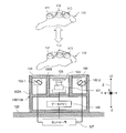
- FIG. 16 is an explanatory diagram showing a configuration example 2 of the photographing device 100 and the authentication device 108 according to the second embodiment.
- the difference from the configuration example 1 of FIG. 14 is that the light source 1600 is provided at a position facing the side surface of the fingertip presentation plate 1400 at the + Z side end portion of the front plate portion 100C of the housing 100A.
- the irradiation light from the light source 1600 is incident from the side surface of the fingertip presentation plate 1400.
- the imaging unit 101 contacts the fingertip presentation plate 1400 while irradiating light from the light source 1600. Take a fingerprint of your fingertips.
- the light incident on the fingertip presentation plate 1400 from the light source 1600 propagates while being totally reflected at the interface between the fingertip presentation plate 1400 and air.
- the refractive index between the moisture on the fingertip surface and the fingertip presentation plate 1400 is the air in the ridge portion which is the convex portion of the fingerprint of the fingertip in contact. It becomes larger than the refractive index. Therefore, the total reflection condition is not satisfied and the light from the light source 1600 is scattered.
- the image pickup unit 101 captures such a fingerprint, and the controller 107 can generate image data of the fingerprint.
- the controller 107 generates image data of blood vessels near the finger base and the image data of the skin surface (finger back surface side) by the light sources 102-4 and 102-5, and generates fingerprint image data by the light source 1600. And can be executed.
- the controller 107 can acquire a plurality of biometric information for one user in one authentication process, highly accurate authentication can be realized without impairing convenience.
- FIG. 17 is an explanatory diagram showing a configuration example 3 of the photographing device 100 and the authentication device 108 according to the second embodiment.
- the difference from the configuration example 1 of FIG. 14 is that the light source 1700 is provided on the + Z side end surface of the front plate portion 100C of the housing 100A which is flush with the fingertip presentation plate 1400.
- the optical axis J of the light source 1700 is in a direction inclined from the Z axis to the fingertip presentation plate 1400 side around the Y axis. As a result, the light source 1700 can irradiate light toward the fingertip presented on the fingertip presentation plate 1400.
- the light from the light sources 102-1 and 102-2 passes through the fingertip presentation plate 1400 and is applied to the fingertip. Even if the amount of light is greatly attenuated when light is transmitted through the fingertip presentation plate 1400 and the fingertip is not irradiated with a sufficient amount of light, the irradiation light from the light source 1700 makes it easy for the irradiation light to hit the vicinity of the contour of the fingertip. Become. Therefore, the controller 107 can generate clear blood vessel image data for the entire finger region.
- the controller 107 determines the controller 107. Instead of increasing the amount of irradiation light from the light sources 102-1 and 102-2, the amount of irradiation light from the light source 1700 may be decreased, and the fingertip may be imaged by the imaging unit 101.
- the light source 1700 is arranged at a position in the + Z direction with respect to the fingertip presentation plate 1400, but the light source 1700 may be arranged at a position in the ⁇ Z direction with respect to the fingertip presentation plate 1400.
- the irradiation light from the light source 1700 passes through the fingertip presentation plate 1400 and is irradiated to the fingertip.
- the height of the housing 100A in the Z-axis direction can be lowered as compared with the configuration shown in FIG. 17, and further miniaturization can be realized.
- the fingertip presentation plate 1400 an example in which the fingertip presentation plate 1400 is provided has been described, but it goes without saying that the same effect can be obtained even when the fingertip presentation plate 1400 is not provided.
- Example 3 is an example in which an auxiliary light source is provided on the inner surface of the housing 100A in the first and second embodiments.
- the controller 107 stably detects the contour of the finger.
- the same components as those in the first and second embodiments are designated by the same reference numerals, and the description thereof will be omitted.
- FIG. 18 is an explanatory diagram showing a configuration example of the photographing device 100 and the authentication device 108 according to the third embodiment.
- (A) is a plan view of the photographing device 100 and the authentication device 108
- (B) is a cross-sectional view of the photographing device 100 and the authentication device 108.
- the front plate portion 100C, the first side plate portion 100D, and the second side plate portion 100E project from the top plate portion 100B in the + Z direction.
- These protruding portions are referred to as a front protruding end 100Ca of the front plate portion 100C, a first side protruding end 100Da of the first side plate portion 100D, and a second side protruding end 100Ea of the second side plate portion 100E, respectively.
- the user's hand 110 is presented in the space 1800 outside the housing 100A surrounded by the front protruding end 100Ca, the first side protruding end 100Da, the second side protruding end 100Ea, and
- the auxiliary light source 1801C is provided on the inner wall surface of the front protruding end 100Ca.
- the auxiliary light source 1801D is provided on the inner wall surface of the first side surface protruding end 100Da.
- the auxiliary light source 1801E is provided on the inner wall surface of the second side surface protruding end 100Ea.
- the auxiliary light source 1801C is a light source along the Y-axis direction, and the auxiliary light sources 1801D and 1801E are light sources along the X-axis direction.
- the auxiliary light sources 1801C, 1801D and 1801E are connected to the controller 107. When the auxiliary light sources 1801C, 1801D, and 1801E are not distinguished, they are simply referred to as auxiliary light sources 1801.
- Auxiliary light sources 1801C, 1801D, 1801E surround fingers 111 to 113 presented in space 1800.
- the auxiliary light source 1801C irradiates light along the Y-axis direction toward the fingertips of the index finger 111, the middle finger 112, and the ring finger 113, and between the fingers.
- the auxiliary light source 1801D irradiates light along the X-axis direction toward the side surface of the index finger 111.
- the auxiliary light source 1801E irradiates light along the X-axis direction toward the side surface of the ring finger 113. In this way, the irradiation light from the auxiliary light source 1801 is applied to the vicinity of the contour of the finger.
- the auxiliary light source 1801 may be further arranged in the + Z direction, assuming that the user presents a finger to the authentication device 108 in a non-contact manner.
- the imaging unit 101 can receive the reflected light having sufficient brightness, and is stable and high. Accurate finger detection is possible.
- the wavelength of the irradiation light from the auxiliary light source 1801 may be the same wavelength as the irradiation light of the light source 102. This facilitates the generation of bright blood vessel image data over the entire finger region. Further, the wavelength of the irradiation light from the auxiliary light source 1801 may be a wavelength different from that of the light source 102. By setting the wavelength of the irradiation light from the auxiliary light source 1801 to a wavelength that is less likely to be included in the ambient light, the background region and the finger region can be further distinguished, and the accuracy of finger detection can be improved.
- the wavelength of the auxiliary light source 1801 May have the same visible light wavelength as the light source 102.
- the contour line of the finger can be stably detected by the color of the irradiation light.
- the controller 107 may control the auxiliary light source 1801 to irradiate with visible light having a wavelength different from that of the light source 102. As a result, it is possible to visually recognize that the authentication device 108 is in the standby state.
- the controller 107 When the controller 107 detects the finger when the user presents the finger in the space 1800 (step S702: Yes), the controller 107 switches the wavelength of the irradiation light from the auxiliary light source 1801 to the same wavelength as the light source 102. , Irradiate visible light and execute the authentication process (authentication status). Since the light source 102 and the auxiliary light source 1801 irradiate visible light having the same wavelength, the controller 107 can brightly photograph the entire finger region. Further, since the wavelength of the irradiation light from the auxiliary light source 1801 changes, the user can visually recognize that the authentication device 108 has changed from the standby state to the authentication state.
- the controller 107 changes the amount of light to be irradiated between the standby state and the authentication state, or changes the lighting pattern of the auxiliary light source 1801 from the blinking state to the constant lighting. May be changed to represent the state transition.
- the controller 107 controls the auxiliary light source 1801 so that when the authentication succeeds or the authentication fails, the lighting pattern changes such as irradiating with a wavelength light different from the standby state or the authentication state or a different amount of light, or turning off the light. As a result, the controller 107 can notify the user of the authentication result.
- the photographing device 100 and the authentication device 108 can be configured as described in (1) to (15) below.
- the above-mentioned photographing apparatus 100 is arranged at a position facing the presented plurality of fingers 111 to 113, and the imaging unit 101 that images the plurality of fingers 111 to 113 and the plurality of fingers 111 to 113.
- the light source 102 can irradiate not only the back surface of the fingers 111 to 113 but also the side surfaces of the fingers 111 to 113, and can suppress the occurrence of insufficient light amount. That is, it is possible to suppress unevenness in the amount of light in the entire plurality of fingers 111 to 113.
- a plurality of the plurality of light sources 102 are arranged in the arrangement direction Y of the plurality of fingers 111 to 113, and a plurality of the plurality of light sources 102 are arranged in the longitudinal direction X of the fingers 111 to 113. You may. As a result, the light source 102 can irradiate light between the fingertips of the fingers 111 to 113 to the root.
- the amount of the first irradiation light from the first light sources (102-1, 102-2) arranged in the longitudinal direction of the fingers 111 to 113 and the fingers 111 to 113 is different from the amount of the second irradiation light from the second light source (102-4, 102-5) arranged in the longitudinal direction of the above and on the root side of the fingers 111 to 113 with respect to the first light source.
- the amount of irradiation light can be changed according to the irradiation position of the fingers 111 to 113.
- the amount of the first irradiation light is larger than the amount of the second irradiation light. As a result, it is possible to suppress the shortage of the amount of light on the fingertip side and to make the amount of light uniform throughout the fingers 111 to 113.
- each of the plurality of light sources 102 has the same first distance to the nearest finger among the plurality of fingers 111 to 113, or the difference between the first distances is the first. They are arranged so as to be within one tolerance range and the second distance to the farthest finger among the plurality of fingers 111 to 113 is the same or the difference between the second distances is within the second tolerance range. As a result, the amount of light can be made uniform across the fingers 111 to 113.
- the plurality of light sources 102 include a light source that irradiates visible light. As a result, the pattern (fingerprint) on the back surface of the fingers 111 to 113 can be photographed.
- the plurality of light sources 102 include a light source that irradiates near infrared light. This makes it possible to photograph the blood vessels of the fingers 111 to 113.
- At least one of the plurality of light sources 102 is passed through the light of a specific wavelength in the irradiation direction (optical axis I) of the plurality of fingers 111 to 113. It has a second optical filter 104. Thereby, a light source that irradiates light including a specific wavelength can be applied to the photographing apparatus 100.
- the second optical filter 104 is a filter that allows visible light to pass through. As a result, the pattern (fingerprint) on the back surface of the fingers 111 to 113 can be photographed.
- the second optical filter 104 is a filter that allows near-infrared light to pass through. This makes it possible to photograph the blood vessels of the fingers 111 to 113.
- the second wavelength of the second irradiation light from the second light source (102-4, 102-5) arranged in the longitudinal direction of the fingers 111 to 113 and closer to the root side of the fingers 111 to 113 than the first light source? different.
- the fingers 111 to 113 can be irradiated with light having different wavelengths depending on the irradiation position of the fingers 111 to 113.
- the first irradiation light is visible light and the second irradiation light is near infrared light. This makes it possible to photograph the pattern (fingerprint) and blood vessels on the back surface of the fingers 111 to 113.
- a fingertip presentation plate 1400 on which a plurality of fingers 111 to 113 can be placed and through which light from a plurality of light sources 102 is transmitted may be provided. ..
- the user can be guided to present the fingertip to the fingertip presentation plate 1400.
- a light source 1600 that illuminates the inside of the fingertip presentation plate 1400 may be provided. As a result, it is possible to suppress the shortage of the amount of light on the fingertip side and to make the amount of light uniform throughout the fingers 111 to 113.
- the photographing apparatus 100 of the above (1) may have a light source control unit 300 for controlling the increase / decrease of the amount of irradiation light from the plurality of light sources 102.
- the photographing device 100 can autonomously control the increase / decrease of the irradiation light amount.
- the photographing device 100 may have a distance measuring sensor 600 that measures a distance D from a plurality of fingers 111 to 113.
- the light source control unit 300 can control the amount of irradiation light for each light source 102 according to the distance D.
- the light source control unit 300 makes the irradiation light amount of the light source 102 having a longer distance D from the fingers 111 to 113 larger than the irradiation light amount of the light source 102 having a shorter distance D from the fingers 111 to 113. Increase / decrease control. As a result, even when the plurality of fingers 111 to 113 are not equidistant from the imaging unit 101, it is possible to irradiate the plurality of fingers 111 to 113 with a uniform amount of light to take a picture by adjusting the amount of light.
- the above-mentioned authentication device 108 is arranged at a position facing the presented plurality of fingers 111 to 113, and has an imaging unit 101 that images the plurality of fingers 111 to 113 and a plurality of fingers 111 to 111.
- a plurality of light sources arranged in the arrangement direction of 113, and the imaging unit 101 irradiates the plurality of fingers 111 to 113 with light from the outside of the facing region 130 facing the plurality of fingers 111 to 113 toward the inside of the facing region 130.
- an image processing unit (controller 107, computer 310) that generates image data of a plurality of fingers 111 to 113 based on output signals from the imaging unit 101, and an image processing unit (controller 107, computer 310).
- the plurality of fingers 111 to 111 to Authenticate 113 Based on the first image data of the plurality of fingers 111 to 113 and the second image data of the plurality of fingers 111 to 113 generated by the image processing unit (controller 107, computer 310), the plurality of fingers 111 to 111 to Authenticate 113.
- the light source 102 can irradiate not only the back surface of the fingers 111 to 113 but also the side surfaces of the fingers 111 to 113, and the finger image obtained from the finger image data can be sharpened. , Authentication accuracy can be improved.
- the present invention is not limited to the above-described embodiment, but includes various modifications and equivalent configurations within the scope of the attached claims.
- the above-described examples have been described in detail in order to explain the present invention in an easy-to-understand manner, and the present invention is not necessarily limited to those having all the described configurations.
- a part of the configuration of one embodiment may be replaced with the configuration of another embodiment.
- the configuration of another embodiment may be added to the configuration of one embodiment.
- other configurations may be added, deleted, or replaced with respect to a part of the configurations of each embodiment.
- each of the above-described configurations, functions, processing units, processing means, etc. may be realized by hardware by designing a part or all of them by, for example, an integrated circuit, and the processor 311 performs each function. It may be realized by software by interpreting and executing the program to be realized.
- Information such as programs, tables, and files that realize each function is recorded in a memory, hard disk, storage device such as SSD (Solid State Drive), or IC (Integrated Circuit) card, SD card, DVD (Digital Any Disc). It can be stored in a medium.
- SSD Solid State Drive
- IC Integrated Circuit
- control lines and information lines indicate those that are considered necessary for explanation, and do not necessarily indicate all the control lines and information lines that are necessary for implementation. In practice, it can be considered that almost all configurations are interconnected.
Abstract
A photographing device including: an imaging unit that is disposed at a location facing a plurality of fingers to be presented, and images the plurality of fingers; and a plurality of light sources that are disposed in an alignment direction of the plurality of fingers, and apply light to the plurality of fingers from outside of an opposing region in which the imaging unit faces the plurality of fingers toward the inside of the opposing region.
Description
本出願は、令和1年(2019年)12月4日に出願された日本出願である特願2019-219636の優先権を主張し、その内容を参照することにより、本出願に取り込む。
This application claims the priority of Japanese Patent Application No. 2019-219636, which is a Japanese application filed on December 4, 2019, and incorporates it into this application by referring to its contents.
本発明は、生体を撮影する撮影装置および生体を撮影して認証する認証装置に関する。
The present invention relates to a photographing device for photographing a living body and an authentication device for photographing and authenticating a living body.
血管中のヘモグロビンとその他の生体組織の近赤外光の吸収特性の違いを利用して撮影した生体画像(血管画像)による生体認証技術が提案されている。ヘモグロビンの吸収率の高い波長である近赤外光を生体に照射し、透過または反射する光を撮像することで血管画像が得られる。指の皮膚表面下には個人ごとに異なる血管の模様(パターン)が存在しており、この血管パターンを鮮明に撮影することで高精度認証が実現可能である。
A biometric authentication technology using a biological image (blood vessel image) taken by utilizing the difference in absorption characteristics of near-infrared light between hemoglobin in a blood vessel and other biological tissues has been proposed. A blood vessel image can be obtained by irradiating a living body with near-infrared light having a high absorption rate of hemoglobin and imaging the transmitted or reflected light. Under the skin surface of the finger, different blood vessel patterns (patterns) exist for each individual, and high-precision authentication can be realized by clearly photographing these blood vessel patterns.
指の血管画像を用いた認証技術を小型な装置サイズで実現するための血管画像の撮影方法の一つとして反射型方式がある。反射型方式は、光源と撮像部を近接して配置し、光源からの照射光を指の腹に照射し、反射する光を撮像して血管画像を取得する方法である。反射型方式である下記特許文献1の生体認証装置は、基板の表面に設けられ光を出力する光源と、ピッチ及び回転方向が異なる複数の回折格子が配置され前記光を回折して照明光を照明対象の照明領域に照射する回折光学素子とを備え、前記照明領域は、前記基板の表面と平行な平面上の前記回折光学素子及び前記光源の占有面積より大きいように構成する。
There is a reflection type method as one of the methods for taking a blood vessel image in order to realize the authentication technology using the blood vessel image of the finger with a small device size. The reflection type method is a method in which a light source and an imaging unit are arranged close to each other, irradiation light from the light source is applied to the pad of a finger, and the reflected light is imaged to acquire a blood vessel image. The biometric authentication device of Patent Document 1 below, which is a reflection type, has a light source provided on the surface of a substrate and outputs light, and a plurality of diffraction gratings having different pitches and rotation directions are arranged to diffract the light to emit illumination light. The illumination area is provided with a diffraction optical element that irradiates the illumination area to be illuminated, and the illumination area is configured to be larger than the occupied area of the diffraction optical element and the light source on a plane parallel to the surface of the substrate.
また、より高い認証精度を実現するためには1本の指だけでなく、複数の指を同時に撮影した血管画像を用いた認証方法が有効である。反射型方式は、生体が装置と非接触な状態でも同時に複数の指の血管画像の撮影が可能なため、利便性の高さと装置の小型化の両立が実現できる。
Further, in order to realize higher authentication accuracy, an authentication method using a blood vessel image obtained by simultaneously photographing not only one finger but also a plurality of fingers is effective. In the reflective method, it is possible to take blood vessel images of a plurality of fingers at the same time even when the living body is not in contact with the device, so that both high convenience and miniaturization of the device can be realized.
指の表面形状は立体的で曲面が多いため、反射型方式では、指の部位ごとに反射光量の違いが生じ、指先や指の側面(輪郭付近)の領域で十分な明るさが得られない。したがって、鮮明な血管画像の撮影が難しいという課題がある。十分な明るさを得られていない不鮮明な血管画像では、指領域を正確に検知できず、認証精度が低下するおそれがある。したがって、同時に複数の指の血管画像を撮影しようとする場合には特に、撮影するすべての指の血管を鮮明に撮影することが課題となる。
Since the surface shape of the finger is three-dimensional and has many curved surfaces, in the reflective method, the amount of reflected light differs depending on the part of the finger, and sufficient brightness cannot be obtained in the area of the fingertip or the side surface of the finger (near the contour). .. Therefore, there is a problem that it is difficult to take a clear blood vessel image. In an unclear blood vessel image in which sufficient brightness is not obtained, the finger area cannot be detected accurately, and the authentication accuracy may decrease. Therefore, it is a problem to clearly capture the blood vessels of all the fingers to be captured, especially when attempting to capture blood vessel images of a plurality of fingers at the same time.
本発明は、撮影対象への光量不足を抑制することを目的とする。
An object of the present invention is to suppress a shortage of light intensity to a photographing target.
本願において開示される発明の一側面となる撮影装置は、提示される複数の指に対向する位置に配置され、前記複数の指を撮像する撮像部と、前記複数の指の配列方向に複数配置され、前記撮像部が前記複数の指と対向する対向領域の外側から前記対向領域の内側に向けて前記複数の指に光を照射する複数の光源と、を有することを特徴とする。
The photographing apparatus which is one aspect of the invention disclosed in the present application is arranged at a position facing the plurality of presented fingers, and a plurality of imaging units for imaging the plurality of fingers and a plurality of imaging devices in the arrangement direction of the plurality of fingers. The imaging unit is characterized by having a plurality of light sources that irradiate the plurality of fingers with light from the outside of the facing region facing the plurality of fingers toward the inside of the facing region.
本願において開示される発明の一側面となる認証装置は、提示される複数の指に対向する位置に配置され、前記複数の指を撮像する撮像部と、前記複数の指の配列方向に複数配置され、前記撮像部が前記複数の指と対向する対向領域の外側から前記対向領域の内側に向けて前記複数の指に光を照射する複数の光源と、前記撮像部からの出力信号に基づいて前記複数の指の画像データを生成する画像処理部と、前記画像処理部によって生成された前記複数の指の第1画像データと、前記画像処理部によって生成された前記複数の指の第2画像データと、に基づいて、前記複数の指を認証する認証部と、を有することを特徴とする。
The authentication device, which is one aspect of the invention disclosed in the present application, is arranged at a position facing the plurality of presented fingers, and a plurality of imaging units for imaging the plurality of fingers and a plurality of the authentication devices in the arrangement direction of the plurality of fingers. Based on the plurality of light sources that irradiate the plurality of fingers with light from the outside of the facing region facing the plurality of fingers toward the inside of the facing region, and the output signals from the imaging unit. An image processing unit that generates image data of the plurality of fingers, a first image data of the plurality of fingers generated by the image processing unit, and a second image of the plurality of fingers generated by the image processing unit. It is characterized by having an authentication unit that authenticates the plurality of fingers based on the data.
本発明の代表的な実施の形態によれば、撮影対象への光量不足を抑制することができる。前述した以外の課題、構成及び効果は、以下の実施例の説明により明らかにされる。
According to a typical embodiment of the present invention, it is possible to suppress a shortage of light intensity to the object to be photographed. Issues, configurations and effects other than those described above will be clarified by the description of the following examples.
<撮影装置および認証装置の構成例>
図1は、実施例1にかかる撮影装置および認証装置の構成例1を示す説明図である。撮影装置100は、被写体として筐体100Aの上面板部100B上方にかざされた手110の指を撮影する。実施例1では、例として、人差し指111、中指112および薬指113を被写体(撮像対象)とする。ただし、被写体となる指111~113は、両手110の10本の指のうち2本以上含まれればよい。なお、指111~113の手110の甲側の面を指111~113のオモテ面と称し、指111~113の手110のひら側の面を指111~113のウラ面と称す。 <Configuration example of imaging device and authentication device>
FIG. 1 is an explanatory diagram showing a configuration example 1 of a photographing device and an authentication device according to the first embodiment. The photographingdevice 100 photographs the finger of the hand 110 held above the upper surface plate portion 100B of the housing 100A as a subject. In the first embodiment, as an example, the index finger 111, the middle finger 112, and the ring finger 113 are used as subjects (imaging targets). However, the fingers 111 to 113 to be the subject may include two or more of the ten fingers of both hands 110. The surface on the back side of the hands 110 of the fingers 111 to 113 is referred to as the front surface of the fingers 111 to 113, and the surface on the palm side of the hands 110 of the fingers 111 to 113 is referred to as the back surface of the fingers 111 to 113.
図1は、実施例1にかかる撮影装置および認証装置の構成例1を示す説明図である。撮影装置100は、被写体として筐体100Aの上面板部100B上方にかざされた手110の指を撮影する。実施例1では、例として、人差し指111、中指112および薬指113を被写体(撮像対象)とする。ただし、被写体となる指111~113は、両手110の10本の指のうち2本以上含まれればよい。なお、指111~113の手110の甲側の面を指111~113のオモテ面と称し、指111~113の手110のひら側の面を指111~113のウラ面と称す。 <Configuration example of imaging device and authentication device>
FIG. 1 is an explanatory diagram showing a configuration example 1 of a photographing device and an authentication device according to the first embodiment. The photographing
図1では、撮影装置100は、筐体100Aと、撮像部101と、光源102と、データメモリ106と、を有する。撮影装置100にコントローラ107が接続された装置が認証装置108である。
In FIG. 1, the photographing apparatus 100 includes a housing 100A, an imaging unit 101, a light source 102, and a data memory 106. The device in which the controller 107 is connected to the photographing device 100 is the authentication device 108.
筐体100Aは、たとえば、設置面120に取り付けまたは載置(以下、総称して「設置」)される。設置面120は、地面、天井面または机など地面に平行な台の表面でもよく、壁など地面に垂直な面でもよい。なお、設置面120に直交する軸をZ軸とし、Z軸において設置面120から離間する方向を+Z方向とし、設置面120に近接する方向を-Z方向とする。また、設置面120は、XY平面に平行である。XY平面はX軸とY軸とにより張られる平面である。図1に示したように、手110は上面板部100Bにかざされるように、撮影装置100および認証装置108は設置される。この場合、X軸は、手110がかざされたときの指の長手方向である。Y軸は、指111~113の配列方向である。
The housing 100A is attached or placed on the installation surface 120 (hereinafter, collectively referred to as "installation"). The installation surface 120 may be a surface of a table parallel to the ground such as the ground, a ceiling surface or a desk, or a surface perpendicular to the ground such as a wall. The axis orthogonal to the installation surface 120 is the Z axis, the direction away from the installation surface 120 on the Z axis is the + Z direction, and the direction close to the installation surface 120 is the −Z direction. Further, the installation surface 120 is parallel to the XY plane. The XY plane is a plane stretched by the X-axis and the Y-axis. As shown in FIG. 1, the photographing device 100 and the authentication device 108 are installed so that the hand 110 is held over the top plate portion 100B. In this case, the X-axis is the longitudinal direction of the finger when the hand 110 is held over. The Y-axis is the arrangement direction of the fingers 111 to 113.
筐体100A内部に撮像部101と複数の光源102(図1では、光源102-1,102-2)とを含む。光源102-1,102-2を区別しない場合は、単に光源102と表記する。また、撮像部101と筐体100Aの上面板部100Bとの間には、第1光学フィルタ103が設けられる。撮像部101は、第1光学フィルタ103を通過した被写体光を受光する。被写体光は、光源102からの照射光が被写体に反射された光(反射光)である。
The housing 100A includes an imaging unit 101 and a plurality of light sources 102 (light sources 102-1 and 102-2 in FIG. 1). When the light sources 102-1 and 102-2 are not distinguished, they are simply referred to as the light source 102. Further, a first optical filter 103 is provided between the image pickup unit 101 and the upper surface plate portion 100B of the housing 100A. The imaging unit 101 receives the subject light that has passed through the first optical filter 103. The subject light is light (reflected light) obtained by reflecting the irradiation light from the light source 102 on the subject.
撮像部101および筐体100Aの上面板部100Bは、提示される手110と対向する。特に、上面板部100Bのうち、指111~113に対向する面を対向面100Baと称す。対向面100Baから+Z方向の領域は、提示される指111~113が撮像部101および対向面100Baと対向する対向領域130である。対向面100Baおよび対向領域130のX軸方向の幅は、たとえば、指111~113の指先から指根元までの長さを包含する幅となる。
The image pickup unit 101 and the top plate portion 100B of the housing 100A face the presented hand 110. In particular, of the top plate portion 100B, the surface facing the fingers 111 to 113 is referred to as the facing surface 100Ba. The region in the + Z direction from the facing surface 100Ba is the facing region 130 in which the presented fingers 111 to 113 face the imaging unit 101 and the facing surface 100Ba. The width of the facing surface 100Ba and the facing region 130 in the X-axis direction is, for example, a width including the length from the fingertip to the finger base of the fingers 111 to 113.
また、撮像部101から+Z方向に存在する上面板部100Bの領域には、光源102の照射光が指111~113のような生体で反射した光を透過させる透光板105が設けられる。透光板105は、たとえば、アクリルやガラスなどの透明な部材で構成される。また、透光板105に、特定の波長光のみを通過させるフィルムが貼着されてもよい。これにより、撮影装置100内部を外部から視認しにくい状態にすることができる。
Further, in the region of the upper surface plate portion 100B existing in the + Z direction from the imaging unit 101, a translucent plate 105 is provided to transmit the light reflected by the living body such as the fingers 111 to 113 of the irradiation light of the light source 102. The translucent plate 105 is made of a transparent member such as acrylic or glass. Further, a film that allows only light having a specific wavelength to pass through may be attached to the light transmitting plate 105. As a result, the inside of the photographing apparatus 100 can be made difficult to see from the outside.
また、光源102から+Z方向に存在する上面板部100Bの領域には、第2光学フィルタ104が設けられる。光源102から第2光学フィルタ104を通過した光が被写体に照射される。第2光学フィルタ104は、光拡散フィルタでもよい。これにより、光源102は、均一な強度の照射光を広範囲に被写体に照射することができる。
Further, a second optical filter 104 is provided in the region of the upper surface plate portion 100B existing in the + Z direction from the light source 102. The light that has passed through the second optical filter 104 from the light source 102 is applied to the subject. The second optical filter 104 may be a light diffusion filter. As a result, the light source 102 can irradiate the subject with irradiation light of uniform intensity over a wide range.
また、第2光学フィルタ104は、偏光フィルタでもよい。これにより、指111~113のような生体に照射して反射された光成分のうち、皮膚表面での鏡面反射成分を低減することができる。したがって、撮影装置100は、生体の血管像をより鮮明に撮像することができる。また、第2光学フィルタ104は、光源102からの照射光の特定の波長のみを透過する帯域フィルタでもよい。これにより、撮像部101が余分な環境光を受光するのを抑制することができる。
Further, the second optical filter 104 may be a polarizing filter. This makes it possible to reduce the specular reflection component on the skin surface among the light components reflected by irradiating the living body such as the fingers 111 to 113. Therefore, the imaging device 100 can capture a blood vessel image of a living body more clearly. Further, the second optical filter 104 may be a band filter that transmits only a specific wavelength of the irradiation light from the light source 102. As a result, it is possible to prevent the imaging unit 101 from receiving excess ambient light.
撮像部101は、たとえば、CMOS(Complementary Metal Oxide Semiconductor)イメージセンサやCCD(Charge Coupled Device)イメージセンサのような撮像素子により構成される。撮像部101の撮像面は、上面板部100Bに対向する。
The image pickup unit 101 is composed of, for example, an image pickup element such as a CMOS (Complementary Metal Oxide Semiconductor) image sensor or a CCD (Charge Coupled Device) image sensor. The imaging surface of the imaging unit 101 faces the top plate portion 100B.
撮像部101は、筐体100A外から上面板部100Bの透光板105および第1光学フィルタ103を介して入射されてくる光を撮像面で受光し、光電変換する。撮像部101は、データメモリ106に接続されており、光電変換した画像データをデータメモリ106に格納する。画像データは、指の血管を示す画像データ(指血管画像データ)でもよく、指紋を示す画像データ(指紋画像データ)でもよい。指血管画像データおよび指紋画像データを総称して、指画像データと称す。データメモリ106は、コントローラ107に接続される。なお、本明細書では、指紋は、少なくとも指先(指の腹)の紋様であり、指先から指の付け根までの指のウラ面の紋様を含んでもよい。
The imaging unit 101 receives the light incident from the outside of the housing 100A through the light transmitting plate 105 of the upper surface plate portion 100B and the first optical filter 103 on the imaging surface and performs photoelectric conversion. The imaging unit 101 is connected to the data memory 106, and stores the photoelectrically converted image data in the data memory 106. The image data may be image data indicating a finger blood vessel (finger blood vessel image data) or image data indicating a fingerprint (fingerprint image data). Finger blood vessel image data and fingerprint image data are collectively referred to as finger image data. The data memory 106 is connected to the controller 107. In the present specification, the fingerprint is at least a pattern on the fingertip (pad of the finger), and may include a pattern on the back surface of the finger from the fingertip to the base of the finger.
光源102は、第2光学フィルタ104を介して、上面板部100Bから+Z方向に存在する被写体に光を照射する。指の血管を撮影する場合には、光源102からの照射光は、たとえば、近赤外光となる。また、指紋を撮影する場合には、光源102からの照射光は、たとえば、可視光(たとえば、青または緑)となる。光源102は、撮像部101を挟む位置に設けられる。すなわち、光源102はY軸方向に配列される。光源102は、X軸方向において、指先から指根元までの間の位置に配置される。このように、各光源102は、対向領域130の外側から対向領域130の内側に向けて指111~113に光を照射する。
The light source 102 irradiates the subject existing in the + Z direction from the top plate portion 100B via the second optical filter 104. When photographing a blood vessel of a finger, the irradiation light from the light source 102 is, for example, near-infrared light. Further, when a fingerprint is photographed, the irradiation light from the light source 102 is, for example, visible light (for example, blue or green). The light source 102 is provided at a position sandwiching the image pickup unit 101. That is, the light sources 102 are arranged in the Y-axis direction. The light source 102 is arranged at a position between the fingertip and the finger base in the X-axis direction. In this way, each light source 102 irradiates the fingers 111 to 113 from the outside of the facing region 130 toward the inside of the facing region 130.
光源102からの照射光の広がりを光芒という。光芒は、被写体となる指111~113の照射範囲となる。換言すれば、光源102は、その光芒が指111~113を含むような位置に配置される。光芒の中心軸を光軸と称す。光軸は、光の照射方向となる。光軸は、Z軸に平行ではなく、Z軸(+Z方向)から所定角度分撮像部101側に傾斜した方向となる。
The spread of the irradiation light from the light source 102 is called a light beam. The light beam is in the irradiation range of the finger 111 to 113 which is the subject. In other words, the light source 102 is arranged at a position where its light beam includes the fingers 111 to 113. The central axis of the optical beam is called the optical axis. The optical axis is the irradiation direction of light. The optical axis is not parallel to the Z axis, but is inclined from the Z axis (+ Z direction) toward the imaging unit 101 by a predetermined angle.
光軸がZ軸に平行な場合、人差し指111の親指側側面および薬指113の小指側側面には十分な光量で光が照射されるが、中指112、人差し指111の中指側側面および薬指113の中指側側面は、光量不足となる。そのため、照射方向を所定角度分撮像部101側に傾斜させることで、人差し指111、中指112、および薬指113の各々に十分な光量の光を照射し、人差し指111、中指112、および薬指113のいずれかの指の側面の光量不足を抑制することができる。
When the optical axis is parallel to the Z axis, the thumb side side surface of the index finger 111 and the little finger side side surface of the ring finger 113 are irradiated with a sufficient amount of light, but the middle finger 112, the middle finger side surface of the index finger 111 and the middle finger of the ring finger 113 are irradiated. The amount of light on the side surface is insufficient. Therefore, by inclining the irradiation direction toward the imaging unit 101 by a predetermined angle, each of the index finger 111, the middle finger 112, and the ring finger 113 is irradiated with a sufficient amount of light, and any of the index finger 111, the middle finger 112, and the ring finger 113 is irradiated. It is possible to suppress the lack of light on the side surface of the finger.
光源102は、筐体100A外のコントローラ107に接続される。コントローラ107は、光源102から照射される光量を制御する。また、コントローラ107は、指111~113の位置を検出したり、指画像データから指111~113内の血管や指紋の特徴を抽出したりする。また、コントローラ107は、データメモリ106に記憶された複数の指画像データを認証してもよい。具体的には、たとえば、コントローラ107は、指画像データを2つデータメモリ106から取得し、指の血管の特徴や指紋の特徴から両指画像データの人差し指111、中指112、および薬指113が同一人物の人差し指111、中指112、および薬指113であるかを認証する。
The light source 102 is connected to the controller 107 outside the housing 100A. The controller 107 controls the amount of light emitted from the light source 102. In addition, the controller 107 detects the positions of the fingers 111 to 113, and extracts the features of the blood vessels and fingerprints in the fingers 111 to 113 from the finger image data. Further, the controller 107 may authenticate a plurality of finger image data stored in the data memory 106. Specifically, for example, the controller 107 acquires two finger image data from the data memory 106, and the index finger 111, the middle finger 112, and the ring finger 113 of the two finger image data are the same from the characteristics of the blood vessels of the fingers and the characteristics of the fingerprint. It authenticates whether the person's index finger 111, middle finger 112, and ring finger 113.
図2は、実施例1にかかる撮影装置100および認証装置108の構成例2を示す説明図である。図2に示す撮影装置100および認証装置108は、図1に示したコントローラ107を筐体100A内部に実装した例である。コントローラ107に認証機能がなければ撮影装置100であり、コントローラ107に認証機能があれば認証装置108である。
FIG. 2 is an explanatory diagram showing a configuration example 2 of the photographing device 100 and the authentication device 108 according to the first embodiment. The photographing device 100 and the authentication device 108 shown in FIG. 2 are examples in which the controller 107 shown in FIG. 1 is mounted inside the housing 100A. If the controller 107 does not have an authentication function, it is the photographing device 100, and if the controller 107 has an authentication function, it is the authentication device 108.
図3は、実施例1にかかる撮影装置100および認証装置108のブロック構成例1を示すブロック図である。撮影装置100は、光源制御部300を有する。光源制御部300は、光源102からの照射光の光量を制御する。光源制御部300は、図1および図2に示したコントローラ107に含まれる。コンピュータ310は、認証機能を含む。コンピュータ310は、図1および図2に示したコントローラ107に含まれる。
FIG. 3 is a block diagram showing a block configuration example 1 of the photographing device 100 and the authentication device 108 according to the first embodiment. The photographing device 100 has a light source control unit 300. The light source control unit 300 controls the amount of irradiation light from the light source 102. The light source control unit 300 is included in the controller 107 shown in FIGS. 1 and 2. The computer 310 includes an authentication function. The computer 310 is included in the controller 107 shown in FIGS. 1 and 2.
コンピュータ310は、プロセッサ311と、記憶デバイス312と、入力デバイス313と、出力デバイス314と、通信インターフェース(通信IF)315と、を有する。プロセッサ311、記憶デバイス312、入力デバイス313、出力デバイス314、および通信IF315は、バス316により接続される。プロセッサ311は、コンピュータ310を制御する。記憶デバイス312は、プロセッサ311の作業エリアとなる。また、記憶デバイス312は、各種プログラムやデータを記憶する非一時的なまたは一時的な記録媒体である。記憶デバイス312としては、たとえば、ROM(Read Only Memory)、RAM(Random Access Memory)、HDD(Hard Disk Drive)、フラッシュメモリがある。入力デバイス313は、データを入力する。入力デバイス313としては、たとえば、キーボード、マウス、タッチパネル、テンキー、スキャナがある。出力デバイス314は、データを出力する。出力デバイス314としては、たとえば、ディスプレイ、プリンタ、スピーカがある。通信IF315は、ネットワークと接続し、データを送受信する。
The computer 310 includes a processor 311, a storage device 312, an input device 313, an output device 314, and a communication interface (communication IF) 315. The processor 311, the storage device 312, the input device 313, the output device 314, and the communication IF 315 are connected by the bus 316. The processor 311 controls the computer 310. The storage device 312 serves as a work area for the processor 311. Further, the storage device 312 is a non-temporary or temporary recording medium for storing various programs and data. Examples of the storage device 312 include a ROM (Read Only Memory), a RAM (Random Access Memory), an HDD (Hard Disk Drive), and a flash memory. The input device 313 inputs data. The input device 313 includes, for example, a keyboard, a mouse, a touch panel, a numeric keypad, and a scanner. The output device 314 outputs data. Output devices 314 include, for example, displays, printers, and speakers. The communication IF 315 connects to the network and transmits / receives data.
上述した記憶デバイス312に記憶されたプログラムとしては、たとえば、画像処理プログラムや光源制御プログラム、認証プログラムがある。画像処理プログラムは、プロセッサ311に、撮像部101からの出力信号に基づいて画像データを生成させるプログラムである。光源制御プログラムは、プロセッサ311に、光源102からの照射光量を増減させるプログラムである。認証プログラムは、プロセッサ311に、記憶デバイス312に記憶された2つの指画像データの同一性を認証させるプログラムである。なお、画像処理、光源制御および認証の各機能についてソフトウェアでの実現例について説明したが専用回路により、画像処理、光源制御および認証の各機能が実現されてもよい。
Examples of the program stored in the storage device 312 described above include an image processing program, a light source control program, and an authentication program. The image processing program is a program that causes the processor 311 to generate image data based on an output signal from the imaging unit 101. The light source control program is a program that causes the processor 311 to increase or decrease the amount of light emitted from the light source 102. The authentication program is a program that causes the processor 311 to authenticate the identity of the two finger image data stored in the storage device 312. Although an example of realization of each function of image processing, light source control, and authentication by software has been described, each function of image processing, light source control, and authentication may be realized by a dedicated circuit.
すなわち、光源制御部300が含まれない撮影装置100は、図1に示した撮影装置100であり、光源制御部300が含まれた撮影装置100は、図2に示した撮影装置100である。また、画像処理、光源制御および認証の各機能を有する認証装置108は、光源制御部300およびコンピュータ310を含み、図1および図2の認証装置108に対応する。
That is, the photographing device 100 including the light source control unit 300 is the photographing device 100 shown in FIG. 1, and the photographing device 100 including the light source control unit 300 is the photographing device 100 shown in FIG. Further, the authentication device 108 having each function of image processing, light source control, and authentication includes a light source control unit 300 and a computer 310, and corresponds to the authentication device 108 of FIGS. 1 and 2.
図4は、実施例1にかかる撮影装置100および認証装置108のブロック構成例2を示すブロック図である。図4に示す撮影装置100および認証装置108は、コンピュータ310を内蔵する。データメモリ106は、記憶デバイス312により実現される。光源制御部300は、記憶デバイス312に記憶されたプログラムをプロセッサ311に実行させることにより実現される。また、認証機能は、記憶デバイス312に記憶されたプログラムをプロセッサ311に実行させることにより実現される。コンピュータ310に認証機能がなければ撮影装置100であり、コンピュータ310に認証機能があれば認証装置108である。
FIG. 4 is a block diagram showing a block configuration example 2 of the photographing device 100 and the authentication device 108 according to the first embodiment. The photographing device 100 and the authentication device 108 shown in FIG. 4 include a computer 310. The data memory 106 is realized by the storage device 312. The light source control unit 300 is realized by causing the processor 311 to execute the program stored in the storage device 312. Further, the authentication function is realized by causing the processor 311 to execute the program stored in the storage device 312. If the computer 310 does not have an authentication function, it is the photographing device 100, and if the computer 310 has an authentication function, it is the authentication device 108.
なお、図1~図4に示した光源102のうち少なくとも1つは、可視光源でもよい。この場合、コントローラ107は、待機中に手110を検出した時、認証処理時、認証成功時、認証失敗時にそれぞれ異なる色の光を発するように可視光源を制御してもよい。これにより、ユーザは認証状態を視認することができる。
Note that at least one of the light sources 102 shown in FIGS. 1 to 4 may be a visible light source. In this case, the controller 107 may control the visible light source so as to emit light of different colors at the time of detecting the hand 110 during standby, at the time of authentication processing, at the time of successful authentication, and at the time of authentication failure. As a result, the user can visually recognize the authentication status.
また、認証の前段階で、コンピュータ310は、入力デバイス313によりユーザIDおよび暗証番号を受け付けたり、通信IF315によりICチップやユーザが所持する通信端末からユーザIDおよび暗証番号をワイヤレス受信したりすることにより、記憶デバイス312に、ユーザIDおよび暗証番号を、当該ユーザの指画像データと関連付けて登録してもよい。
Further, in the pre-authentication stage, the computer 310 accepts the user ID and the password by the input device 313, and wirelessly receives the user ID and the password from the IC chip or the communication terminal possessed by the user by the communication IF 315. Therefore, the user ID and the personal identification number may be registered in the storage device 312 in association with the finger image data of the user.
また、コンピュータ310は、上述のように入力デバイス313または通信IF315からユーザIDおよび暗証番号と、指画像データと、を取得することにより、記憶デバイス312に記憶されているユーザIDおよび暗証番号に関連付けられる指画像データを特定し、両指画像データを認証してもよい(いわゆる1対1認証)。なお、コンピュータ310は、記憶デバイス312に記憶されている指画像データ群から、今回入力された指画像データと一致する指画像データを特定してもよい(いわゆる1対N認証)。
Further, the computer 310 associates the user ID and the password and the finger image data stored in the storage device 312 with the user ID and the password by acquiring the user ID and the password and the finger image data from the input device 313 or the communication IF 315 as described above. The finger image data to be used may be specified and both finger image data may be authenticated (so-called one-to-one authentication). The computer 310 may specify finger image data that matches the finger image data input this time from the finger image data group stored in the storage device 312 (so-called 1-to-N authentication).
また、図1~図4に示した撮影装置100および認証装置108において、光源102からの照射光は、複数の異なる波長の光を含んでもよい。たとえば、撮像部101が、たとえば、カラーカメラのような波長感度特性の異なる複数のセンサにより構成される場合、撮像部101は、光源102から複数の異なる波長光を同時に照射して、指111~113からの反射光により指111~113を撮影する。これにより、コントローラ107は、各センサの波長感度特性の違いを利用して、光源102から光が照射されている指領域と照射されていない背景領域とを効率的に分離することができる。
Further, in the photographing apparatus 100 and the authentication apparatus 108 shown in FIGS. 1 to 4, the irradiation light from the light source 102 may include light having a plurality of different wavelengths. For example, when the image pickup unit 101 is composed of a plurality of sensors having different wavelength sensitivity characteristics such as a color camera, the image pickup unit 101 simultaneously irradiates a plurality of different wavelength lights from the light source 102, and the fingers 111 to 111 to The fingers 111 to 113 are photographed by the reflected light from 113. As a result, the controller 107 can efficiently separate the finger region irradiated with light from the light source 102 and the background region not illuminated by the light source 102 by utilizing the difference in the wavelength sensitivity characteristics of each sensor.
また、光源102は、血管撮影用の近赤外光だけでなく皮膚の表面の凹凸構造である指紋の撮影に適した波長の光を照射してもよい。この場合、コンピュータ310は、指111~113の血管および指紋を利用したマルチモーダル認証を行うことができる。このように、光源102ごとに異なる波長光を用いる場合、第2光学フィルタ104の各々は、各波長のみを透過させる帯域フィルタでもよい。また、第2光学フィルタ104は、複数の波長を包含する1つの広い範囲の波長帯を透過する帯域フィルタでもよい。
Further, the light source 102 may irradiate not only near-infrared light for angiography but also light having a wavelength suitable for photographing fingerprints, which is an uneven structure on the surface of the skin. In this case, the computer 310 can perform multi-modal authentication using the blood vessels of the fingers 111 to 113 and the fingerprint. As described above, when different wavelength light is used for each light source 102, each of the second optical filters 104 may be a band filter that transmits only each wavelength. Further, the second optical filter 104 may be a band filter that transmits one wide wavelength band including a plurality of wavelengths.
<光源102からの照射例>
複数の指111~113の直下、すなわち、撮像部101近傍に単一光源を配置した場合は、指111~113の腹の中央付近はほぼ水平面とみなされて強い照射光が当たる。これにより、撮像部101は十分な明るさの反射光を受光できる。一方で、指111~113の腹から遠い他の指の輪郭付近や指先付近は、指111~113の曲面形状によって、照射光が当たりにくくなる。このような単一光源の配置では、撮像部101は十分な明るさの反射光を受光できないため暗くなり、コントローラ107は、鮮明な指画像となる指画像データを生成することができない。 <Example of irradiation from thelight source 102>
When a single light source is arranged directly under the plurality offingers 111 to 113, that is, in the vicinity of the imaging unit 101, the vicinity of the center of the abdomen of the fingers 111 to 113 is regarded as a horizontal plane and is exposed to strong irradiation light. As a result, the image pickup unit 101 can receive the reflected light having sufficient brightness. On the other hand, the curved surface shape of the fingers 111 to 113 makes it difficult for the irradiation light to hit the vicinity of the contour of the other fingers and the vicinity of the fingertips far from the pad of the fingers 111 to 113. In such an arrangement of a single light source, the imaging unit 101 cannot receive the reflected light having sufficient brightness, so that it becomes dark, and the controller 107 cannot generate finger image data that becomes a clear finger image.
複数の指111~113の直下、すなわち、撮像部101近傍に単一光源を配置した場合は、指111~113の腹の中央付近はほぼ水平面とみなされて強い照射光が当たる。これにより、撮像部101は十分な明るさの反射光を受光できる。一方で、指111~113の腹から遠い他の指の輪郭付近や指先付近は、指111~113の曲面形状によって、照射光が当たりにくくなる。このような単一光源の配置では、撮像部101は十分な明るさの反射光を受光できないため暗くなり、コントローラ107は、鮮明な指画像となる指画像データを生成することができない。 <Example of irradiation from the
When a single light source is arranged directly under the plurality of
図5は、光源102からの照射例1を示す説明図である。光源102は、指111~113の配列方向Yに沿って外側の指よりもさらに外側に位置するようにあらかじめ配置される。光軸Iは、Z軸から他方の光源102が存在する方向へX軸回りに所定角度θ分傾斜した方向である。これにより、光源102-1は、人差し指111のウラ面および親指側側面111Aと、中指112のウラ面および人差し指側側面112Aと、薬指113のウラ面および中指側側面113Aと、を照射する(光芒500に含まれる)。また、光源102-2は、薬指113のウラ面および中指側側面113Bと、中指112のウラ面および人差し指側側面112Bと、人差し指111のウラ面および親指側側面111Bと、を照射する。
FIG. 5 is an explanatory diagram showing an irradiation example 1 from the light source 102. The light source 102 is arranged in advance so as to be located further outside the outer finger along the arrangement direction Y of the fingers 111 to 113. The optical axis I is a direction inclined by a predetermined angle θ from the Z axis in the direction in which the other light source 102 exists around the X axis. As a result, the light source 102-1 irradiates the back surface and thumb side side surface 111A of the index finger 111, the back surface and index finger side side surface 112A of the middle finger 112, and the back surface and middle finger side side surface 113A of the ring finger 113 (light beam). Included in 500). Further, the light source 102-2 irradiates the back surface and the middle finger side side surface 113B of the ring finger 113, the back surface and the index finger side side surface 112B of the middle finger 112, and the back surface and the thumb side side surface 111B of the index finger 111.
このように、各光源102は、光源102の位置から遠い指の輪郭付近に十分な光を照射することができる。なお、光軸Iを撮像部101側に傾ける代わりに、照射位置からの距離が遠いほど照射光量が強くなるようなレンズを用いてもよい。これにより、光源102は、その照射位置から遠い指の輪郭付近に十分な光量の光を照射することができる。
In this way, each light source 102 can irradiate sufficient light near the contour of the finger far from the position of the light source 102. Instead of tilting the optical axis I toward the imaging unit 101, a lens may be used in which the amount of irradiation light becomes stronger as the distance from the irradiation position increases. As a result, the light source 102 can irradiate a sufficient amount of light near the contour of the finger far from the irradiation position.
このようにして、光源102からの照射光が指111~113の腹の中央付近だけでなく指111~113の輪郭付近にも強く当たるようになり、撮像部101は指領域の全域で十分な明るさの反射光を受光する。これにより、コントローラ107は、鮮明な指画像となる指画像データを生成することができる。なお、複数の光源102を同時に照射すると、それぞれの照射光が重なり合う領域が存在する。このため、照射光が重なり強め合うことを考慮した上で、すべての指の全領域が均一な明るさとなるように光源102の配置が決められ、かつ、コントローラ107は照射光の強さを調整することになる。具体的には、たとえば、各光源102において、最も近い指までの距離が同一またはこれらの距離の差が公差範囲内で、かつ、最も遠い指までの距離が同一またはこれらの距離の差が公差範囲内となるように配置される。
In this way, the irradiation light from the light source 102 strongly hits not only the vicinity of the center of the abdomen of the fingers 111 to 113 but also the vicinity of the contours of the fingers 111 to 113, and the imaging unit 101 is sufficient in the entire area of the finger region. Receives reflected light of brightness. As a result, the controller 107 can generate finger image data that becomes a clear finger image. When a plurality of light sources 102 are irradiated at the same time, there is a region where the irradiation lights overlap each other. Therefore, the arrangement of the light source 102 is determined so that the entire area of all the fingers has uniform brightness, and the controller 107 adjusts the intensity of the irradiation light, taking into consideration that the irradiation light overlaps and strengthens each other. Will be done. Specifically, for example, in each light source 102, the distance to the nearest finger is the same or the difference between these distances is within the tolerance range, and the distance to the farthest finger is the same or the difference between these distances is the tolerance. Arranged so as to be within the range.
図6は、光源102からの照射例2を示す説明図である。図6は、図5の構成において、撮像部101の近傍に測距センサ600を設けた例である。測距センサ600は、設置面120からの+Z方向の距離が同一となるような筐体100A内の位置に設置される。測距センサ600は、指111~113までの距離D、すなわち、指111~113と撮像部101との間の距離Dを検出する。具体的には、たとえば、測距センサ600は、赤外光を指111~113に照射してから指111~113からの反射光を受光するまでの時間差により、指111~113までの距離Dを検出する。また、測距センサ600は、指111~113との間の静電容量により、指111~113までの距離Dを検出してもよい。
FIG. 6 is an explanatory diagram showing an irradiation example 2 from the light source 102. FIG. 6 is an example in which the distance measuring sensor 600 is provided in the vicinity of the imaging unit 101 in the configuration of FIG. The distance measuring sensor 600 is installed at a position in the housing 100A such that the distance from the installation surface 120 in the + Z direction is the same. The distance measuring sensor 600 detects the distance D between the fingers 111 and 113, that is, the distance D between the fingers 111 and 113 and the imaging unit 101. Specifically, for example, the distance measuring sensor 600 has a distance D from the fingers 111 to 113 due to a time difference between irradiating the fingers 111 to 113 with infrared light and receiving the reflected light from the fingers 111 to 113. Is detected. Further, the distance measuring sensor 600 may detect the distance D between the fingers 111 and 113 based on the capacitance between the fingers 111 and 113.
このように、コントローラ107は、距離Dに応じて光源102からの光量を増減制御する。たとえば、コントローラ107は、距離Dが短くなるほど光源102の照射光量を減少させ、距離Dが長くなるほど光源102の照射光量を増加させる。
In this way, the controller 107 controls the amount of light from the light source 102 to increase or decrease according to the distance D. For example, the controller 107 decreases the irradiation light amount of the light source 102 as the distance D becomes shorter, and increases the irradiation light amount of the light source 102 as the distance D becomes longer.
<指画像データの登録処理手順>
図7は、指画像データの登録処理手順例を示すフローチャートである。図7では、一例として実行主体を認証装置108とするが、撮影装置100でもよい。上面板部100Bに手110がかざされると、認証装置108は、指111~113の検出を実行する(ステップS701)。具体的には、たとえば、撮像部101は、指111~113の環境光(または光源102からの所定光量の照射光)からの反射光を受光して光電変換し、2値の画像データを生成する。そして、コントローラ107は、2値の画像データの主要被写体と背景とを分離し、主要被写体の形状が指111~113であるか否かを判断する。 <Procedure for registering finger image data>
FIG. 7 is a flowchart showing an example of a finger image data registration processing procedure. In FIG. 7, the executing subject is theauthentication device 108 as an example, but the photographing device 100 may also be used. When the hand 110 is held over the top plate portion 100B, the authentication device 108 executes the detection of the fingers 111 to 113 (step S701). Specifically, for example, the imaging unit 101 receives the reflected light from the ambient light of the fingers 111 to 113 (or the irradiation light of a predetermined amount of light from the light source 102) and performs photoelectric conversion to generate binary image data. To do. Then, the controller 107 separates the main subject and the background of the binary image data, and determines whether or not the shape of the main subject is the fingers 111 to 113.
図7は、指画像データの登録処理手順例を示すフローチャートである。図7では、一例として実行主体を認証装置108とするが、撮影装置100でもよい。上面板部100Bに手110がかざされると、認証装置108は、指111~113の検出を実行する(ステップS701)。具体的には、たとえば、撮像部101は、指111~113の環境光(または光源102からの所定光量の照射光)からの反射光を受光して光電変換し、2値の画像データを生成する。そして、コントローラ107は、2値の画像データの主要被写体と背景とを分離し、主要被写体の形状が指111~113であるか否かを判断する。 <Procedure for registering finger image data>
FIG. 7 is a flowchart showing an example of a finger image data registration processing procedure. In FIG. 7, the executing subject is the
なお、ステップS701では、認証装置108は、光源102を点滅させて撮影し、撮影した画像データの輝度変化を利用して指111~113の検出を実行してもよい。また、測距センサ600が内蔵されている場合、認証装置108は、測距センサ600を用いて所定の位置または一定の範囲内に接近した手110の存在を検出してもよい。また、光源102の点滅および測距センサ600による測距を併用してもよい。
Note that in step S701, the authentication device 108 may take a picture by blinking the light source 102, and may execute the detection of the fingers 111 to 113 by utilizing the change in the brightness of the taken image data. Further, when the distance measuring sensor 600 is built in, the authentication device 108 may detect the presence of the hand 110 approaching a predetermined position or within a certain range by using the distance measuring sensor 600. Further, the blinking of the light source 102 and the distance measurement by the distance measurement sensor 600 may be used together.
指111~113が検出されない場合は(ステップS702:No)、ステップS701に戻る。指111~113が検出された場合(ステップS702:Yes)、認証装置108は、光源制御を実行する(ステップS703)。光源制御(ステップS703)は、光源102の光量を制御する処理である。光源制御(ステップS703)の詳細は、図10で後述する。光源制御(ステップS703)により調整された光量で光源102から照射された結果、撮像部101は指111~113からの反射光を受光し、画像処理により指画像データを生成する(ステップS704)。生成された指画像データは、データメモリ106または記憶デバイス312に格納される。
If fingers 111 to 113 are not detected (step S702: No), the process returns to step S701. When the fingers 111 to 113 are detected (step S702: Yes), the authentication device 108 executes the light source control (step S703). The light source control (step S703) is a process of controlling the amount of light of the light source 102. Details of the light source control (step S703) will be described later with reference to FIG. As a result of being irradiated from the light source 102 with the amount of light adjusted by the light source control (step S703), the imaging unit 101 receives the reflected light from the fingers 111 to 113 and generates finger image data by image processing (step S704). The generated finger image data is stored in the data memory 106 or the storage device 312.
認証装置108は、生成された指画像データから指領域を画像処理により検出し(ステップS705)、指画像データを画像処理により正規化する(ステップS706)。正規化とは、検出した指の位置に基づいて、指の位置変動および姿勢変動による拡大率やゆがみを補正する処理である。そして、認証装置108は、正規化された指画像データから指血管または指紋の特徴データを画像処理により抽出する(ステップS707)。認証装置108は、特徴データをデータメモリ106または記憶デバイス312に格納する(ステップS708)。なお、ステップS708では、認証装置108は特徴データを格納したが、特徴データの抽出(ステップS707)を実行せずに、指画像データをデータメモリ106または記憶デバイス312に格納してもよい。
The authentication device 108 detects the finger region from the generated finger image data by image processing (step S705), and normalizes the finger image data by image processing (step S706). Normalization is a process of correcting the enlargement ratio and distortion due to finger position fluctuation and posture fluctuation based on the detected finger position. Then, the authentication device 108 extracts the feature data of the finger blood vessel or the fingerprint from the normalized finger image data by image processing (step S707). The authentication device 108 stores the feature data in the data memory 106 or the storage device 312 (step S708). Although the authentication device 108 stores the feature data in step S708, the finger image data may be stored in the data memory 106 or the storage device 312 without executing the feature data extraction (step S707).
<指画像データの認証処理手順>
図8は、指画像データの認証処理手順例を示すフローチャートである。図8では、一例として実行主体を認証装置108とするが、撮影装置100でもよい。ただし、撮影装置100が実行主体である場合、ステップS808~S811は、撮影装置100外のコントローラ107またはコンピュータ310によって実行される。なお、ステップS701~S707は、照合対象の指に対する処理であるが、図7と共通する処理であるため説明を省略する。また、図7において、特徴データ抽出(ステップS707)を実行せずに指画像データを格納した場合、ステップS707で照合対象と比較される比較対象の指画像データについても特徴データ抽出が実行される。 <Finger image data authentication processing procedure>
FIG. 8 is a flowchart showing an example of a finger image data authentication processing procedure. In FIG. 8, the executing subject is theauthentication device 108 as an example, but the photographing device 100 may also be used. However, when the photographing device 100 is the execution subject, steps S808 to S811 are executed by the controller 107 or the computer 310 outside the photographing device 100. Although steps S701 to S707 are processes for the finger to be collated, the description thereof will be omitted because they are the same processes as those in FIG. 7. Further, in FIG. 7, when the finger image data is stored without executing the feature data extraction (step S707), the feature data extraction is also executed for the finger image data of the comparison target to be compared with the collation target in step S707. ..
図8は、指画像データの認証処理手順例を示すフローチャートである。図8では、一例として実行主体を認証装置108とするが、撮影装置100でもよい。ただし、撮影装置100が実行主体である場合、ステップS808~S811は、撮影装置100外のコントローラ107またはコンピュータ310によって実行される。なお、ステップS701~S707は、照合対象の指に対する処理であるが、図7と共通する処理であるため説明を省略する。また、図7において、特徴データ抽出(ステップS707)を実行せずに指画像データを格納した場合、ステップS707で照合対象と比較される比較対象の指画像データについても特徴データ抽出が実行される。 <Finger image data authentication processing procedure>
FIG. 8 is a flowchart showing an example of a finger image data authentication processing procedure. In FIG. 8, the executing subject is the
ステップS707の実行後、認証装置108は、既登録である比較対象の特徴データをデータメモリ106または記憶デバイス312から読み出し、照合対象の特徴データと照合する(ステップS808)。具体的には、たとえば、認証装置108は、特徴データの位置の同一性と、特徴の同一性と、により、照合スコアを算出する。
After executing step S707, the authentication device 108 reads the registered feature data of the comparison target from the data memory 106 or the storage device 312 and collates it with the feature data of the collation target (step S808). Specifically, for example, the authentication device 108 calculates the collation score based on the identity of the position of the feature data and the identity of the feature.
位置の同一性とは、たとえば、照合対象の特徴データの位置と同一または許容範囲内における比較対象の特徴データの存否である。特徴の同一性とは、たとえば、位置の同一性がある照合対象の特徴データと比較対象の特徴データとの間において、各特徴データが示す血管または指紋の形状が同一または形状の相違が許容範囲内であることである。認証装置108は、特徴データの位置の同一性および特徴の同一性を満たす特徴データが多いほど照合スコアは高くなる。
The identity of the position is, for example, the existence or nonexistence of the feature data to be compared within the same range as the position of the feature data to be collated or within the permissible range. The feature identity means, for example, that the shape of the blood vessel or fingerprint indicated by each feature data is the same or the difference in shape is acceptable between the feature data of the collation target having the same position and the feature data of the comparison target. To be within. In the authentication device 108, the more feature data satisfying the position identity and feature identity of the feature data, the higher the collation score.
そして、認証装置108は、照合スコアがしきい値THより大きいか否かを判断する(ステップS809)。照合スコアがしきい値TH以下である場合(ステップS809:No)、認証装置108はタイムアウトであるか否かを判断する(ステップS810)。タイムアウト時間を経過していない場合(ステップS810:No)、ステップS703に戻る。一方、タイムアウト時間を経過した場合(ステップS810:Yes)、認証処理は終了する。また、ステップS809において、照合スコアがしきい値THより大きい場合(ステップS809:Yes)、認証装置108は、認証成功後処理を実行し(ステップS811)、認証処理が終了する。
Then, the authentication device 108 determines whether or not the collation score is larger than the threshold value TH (step S809). When the collation score is equal to or less than the threshold value TH (step S809: No), the authentication device 108 determines whether or not the time-out has occurred (step S810). If the time-out time has not elapsed (step S810: No), the process returns to step S703. On the other hand, when the timeout time has elapsed (step S810: Yes), the authentication process ends. Further, in step S809, when the collation score is larger than the threshold value TH (step S809: Yes), the authentication device 108 executes post-authentication processing (step S811), and the authentication process ends.
<光源制御(ステップS703)>
図9は、図7および図8に示した光源制御(ステップS703)の詳細な処理手順例を示すフローチャートである。ステップS702のあと、認証装置108は、指111~113の検出で用いた画像データを取得し(ステップS901)、複数の指111~113の各領域を特定する(ステップS902)。認証装置108は、特定した指領域の明るさを、ステップS901で取得した指画像データの輝度情報から算出する。つぎに、認証装置108は、ステップS903で算出した指領域の明るさに基づいて、指領域が適切な明るさとなるように光源102の光量値を決定する(ステップS904)。そして、認証装置108は、ステップS904で決定した光量値で光源102を点灯して(ステップS905)、ステップS704に移行する。 <Light source control (step S703)>
FIG. 9 is a flowchart showing a detailed processing procedure example of the light source control (step S703) shown in FIGS. 7 and 8. After step S702, theauthentication device 108 acquires the image data used in the detection of the fingers 111 to 113 (step S901), and identifies each region of the plurality of fingers 111 to 113 (step S902). The authentication device 108 calculates the brightness of the specified finger region from the brightness information of the finger image data acquired in step S901. Next, the authentication device 108 determines the light amount value of the light source 102 so that the finger region has an appropriate brightness based on the brightness of the finger region calculated in step S903 (step S904). Then, the authentication device 108 turns on the light source 102 with the light amount value determined in step S904 (step S905), and proceeds to step S704.
図9は、図7および図8に示した光源制御(ステップS703)の詳細な処理手順例を示すフローチャートである。ステップS702のあと、認証装置108は、指111~113の検出で用いた画像データを取得し(ステップS901)、複数の指111~113の各領域を特定する(ステップS902)。認証装置108は、特定した指領域の明るさを、ステップS901で取得した指画像データの輝度情報から算出する。つぎに、認証装置108は、ステップS903で算出した指領域の明るさに基づいて、指領域が適切な明るさとなるように光源102の光量値を決定する(ステップS904)。そして、認証装置108は、ステップS904で決定した光量値で光源102を点灯して(ステップS905)、ステップS704に移行する。 <Light source control (step S703)>
FIG. 9 is a flowchart showing a detailed processing procedure example of the light source control (step S703) shown in FIGS. 7 and 8. After step S702, the
なお、ステップS903で算出される指領域の明るさは、たとえば、指画像データ中の指領域の平均輝度値としてもよい。平均輝度値は、検出した指111~113ごとに個別に算出されてもよいし、検出したすべての指111~113の輝度値の平均でもよい。さらに、平均輝度値を算出する指領域は、指111~113の全領域を用いるだけでなく、指先と指根元との間である中間位置などの局所領域を用いることもできる。
The brightness of the finger region calculated in step S903 may be, for example, the average brightness value of the finger region in the finger image data. The average brightness value may be calculated individually for each of the detected fingers 111 to 113, or may be the average of the brightness values of all the detected fingers 111 to 113. Further, as the finger region for calculating the average brightness value, not only the entire region of the fingers 111 to 113 can be used, but also a local region such as an intermediate position between the fingertip and the finger base can be used.
また、ステップS904の光量値の決定を行う際、認証装置108は、はじめに画像データにおける指領域の適切な明るさ(たとえば、平均輝度)を具体的な目標値としてあらかじめ設定しておく。そして、認証装置108は、ステップS903で算出した明るさが目標値の明るさとなるように照射光量を調整することで、指111~113までの距離D(高さ)が変動する場合でも、光源102は指111~113に均一な強度の光を照射することができる。
Further, when determining the light amount value in step S904, the authentication device 108 first sets an appropriate brightness (for example, average brightness) of the finger region in the image data as a specific target value in advance. Then, the authentication device 108 adjusts the irradiation light amount so that the brightness calculated in step S903 becomes the brightness of the target value, so that even if the distance D (height) from the fingers 111 to 113 fluctuates, the light source 102 can irradiate the fingers 111 to 113 with light of uniform intensity.
光量値の具体的な決定方法としては、光量値を1段階ずつ変化させる方法がある。光源102が照射する光量値を予め数段階に設定しておき、初期光量値で照射して生成された画像データの指領域の明るさが、目標値よりも暗い場合は、認証装置108は、光量値を1段階大きくする。一方で、指領域の明るさが目標値よりも明るい場合は、認証装置108は、光量値を1段階小さくする。
As a specific method for determining the light intensity value, there is a method of changing the light intensity value step by step. When the light intensity value emitted by the light source 102 is set in several steps in advance and the brightness of the finger region of the image data generated by irradiating with the initial light intensity value is darker than the target value, the authentication device 108 sets the authentication device 108. Increase the light intensity value by one step. On the other hand, when the brightness of the finger region is brighter than the target value, the authentication device 108 reduces the light intensity value by one step.
光量値の別の決定方法としては、光源102からの照射光の光量値と指領域の明るさとの相関を利用する方法がある。認証装置108(コントローラ107)は、光量値と指領域の明るさとの関係を表す関数の値に基づいて、目標値となる指領域の明るさに対応する光量値で光源102を照射するように制御する。
Another method for determining the light intensity value is to use the correlation between the light intensity value of the irradiation light from the light source 102 and the brightness of the finger region. The authentication device 108 (controller 107) irradiates the light source 102 with a light amount value corresponding to the target value of the finger area brightness based on the value of a function representing the relationship between the light amount value and the finger area brightness. Control.
図10は、光源102の照射光量と指領域の明るさとの関係性の一例を示すグラフである。グラフ1000の横軸は、指領域の明るさ(たとえば、平均輝度)であり、縦軸は光源からの光量値である。指領域の明るさxと光源が照射する光量値yとの関係が線形近似できると仮定すると、明るさxと光量値yとの関係は、下記式(1)で表すことができる。
FIG. 10 is a graph showing an example of the relationship between the amount of irradiation light of the light source 102 and the brightness of the finger region. The horizontal axis of the graph 1000 is the brightness of the finger region (for example, the average brightness), and the vertical axis is the amount of light from the light source. Assuming that the relationship between the brightness x of the finger region and the light amount value y emitted by the light source can be linearly approximated, the relationship between the brightness x and the light amount value y can be expressed by the following equation (1).
y=αx+β・・・(1)
Y = αx + β ... (1)
上記式(1)のαおよびβは、環境や指の違いによって変化するパラメータであり、指領域の明るさxを算出する度に毎回計算して求められる。式(1)の関数が決定した後は、認証装置108は、目標となる指領域の明るさx′を上記式(1)に代入することで明るさx′に相当する光量値y′を求め、光源102を光量値y′で点灯する。
Α and β in the above equation (1) are parameters that change depending on the environment and the difference in the finger, and are calculated every time the brightness x of the finger region is calculated. After the function of the equation (1) is determined, the authentication device 108 substitutes the brightness x'of the target finger region into the above equation (1) to obtain the light quantity value y'corresponding to the brightness x'. The light source 102 is lit with a light quantity value y'.
図10では、光量値と指領域の明るさとの関係が線形近似できる場合を例に説明したが、線形近似できない場合(関係性が非線形)であっても同様に光量制御することが可能である。
In FIG. 10, a case where the relationship between the light amount value and the brightness of the finger region can be linearly approximated has been described as an example, but even if the relationship cannot be linearly approximated (the relationship is non-linear), the light amount can be controlled in the same manner. ..
図11は、撮影装置100および認証装置108に対する手110の位置の変化を示す説明図である。光源102からを一定の光量で照射する場合、ユーザが提示する手110のZ軸方向の高さが変動すると、手110と光源102とのZ方向の距離に応じて指111~113に照射される光量が変動し、指111~113からの反射光量の過不足が発生する。その結果、指111~113ごとに指領域の明るさが異なって、安定した指画像データが生成できない恐れがある。測距センサ600が利用できる場合には、認証装置108は、測定した距離Dに応じて光源102の照射光量を制御し、指111~113に常に均一な強度の光を照射することができる。すなわち、認証装置108は、距離Dに応じて光源102からの光量を増減制御する。たとえば、認証装置108は、距離Dが短くなるほど光源102からの光量を減少させ、距離Dが長くなるほど光源102からの光量を増加させる。
FIG. 11 is an explanatory diagram showing a change in the position of the hand 110 with respect to the photographing device 100 and the authentication device 108. When irradiating from the light source 102 with a constant amount of light, when the height of the hand 110 presented by the user in the Z-axis direction fluctuates, the fingers 111 to 113 are irradiated according to the distance between the hand 110 and the light source 102 in the Z direction. The amount of light reflected fluctuates, causing excess or deficiency of the amount of reflected light from the fingers 111 to 113. As a result, the brightness of the finger region differs for each finger 111 to 113, and there is a possibility that stable finger image data cannot be generated. When the distance measuring sensor 600 is available, the authentication device 108 can control the amount of light emitted from the light source 102 according to the measured distance D, and can always irradiate the fingers 111 to 113 with light of uniform intensity. That is, the authentication device 108 controls the increase / decrease of the amount of light from the light source 102 according to the distance D. For example, the authentication device 108 decreases the amount of light from the light source 102 as the distance D becomes shorter, and increases the amount of light from the light source 102 as the distance D becomes longer.
<手110の姿勢変動に応じた光量調整例>
図12は、手110の姿勢変動に応じた光量調整例1を示す説明図である。図12では、手110がX軸回りに回転している状態を示す。X軸回りの回転はロール(回転)である。ロール回転による指の姿勢変動により、被写体である人差し指111、中指112および薬指113のZ軸方向の高さが異なる。 <Example of adjusting the amount of light according to the posture change of thehand 110>
FIG. 12 is an explanatory diagram showing an example 1 of adjusting the amount of light according to the change in the posture of thehand 110. FIG. 12 shows a state in which the hand 110 is rotating around the X axis. The rotation around the X axis is a roll (rotation). The heights of the index finger 111, the middle finger 112, and the ring finger 113, which are the subjects, differ in the Z-axis direction due to the change in the posture of the finger due to the roll rotation.
図12は、手110の姿勢変動に応じた光量調整例1を示す説明図である。図12では、手110がX軸回りに回転している状態を示す。X軸回りの回転はロール(回転)である。ロール回転による指の姿勢変動により、被写体である人差し指111、中指112および薬指113のZ軸方向の高さが異なる。 <Example of adjusting the amount of light according to the posture change of the
FIG. 12 is an explanatory diagram showing an example 1 of adjusting the amount of light according to the change in the posture of the
このような場合、コントローラ107は、光源102-1,102-2の各照射光量を変更することで、すべての指領域の明るさを均一化して指画像データを生成することができる。たとえば、コントローラ107は、生成した指画像データにおける人差し指111の指領域の明るさに基づいて光源102-1の照射光量を決定し、薬指113の指領域の明るさに基づいて光源102-2の照射光量を決定する。このように、コントローラ107は、光源102-1,102-2について、距離が最も近い指の明るさに基づいて照射光量を決定する。したがって、コントローラ107は、図12のようなロール回転の場合、光源102-1を光源102-2よりも強い光量で照射するよう制御し、撮像部101により指全体を均一な明るさで撮影する。
In such a case, the controller 107 can generate finger image data by making the brightness of all finger regions uniform by changing the amount of each irradiation light of the light sources 102-1 and 102-2. For example, the controller 107 determines the amount of irradiation light of the light source 102-1 based on the brightness of the finger region of the index finger 111 in the generated finger image data, and determines the irradiation light amount of the light source 102-1 based on the brightness of the finger region of the ring finger 113. Determine the amount of irradiation light. In this way, the controller 107 determines the amount of irradiation light for the light sources 102-1 and 102-2 based on the brightness of the finger closest to the distance. Therefore, in the case of roll rotation as shown in FIG. 12, the controller 107 controls the light source 102-1 to irradiate the light source 102-1 with a stronger amount of light than the light source 102-2, and the imaging unit 101 photographs the entire finger with uniform brightness. ..
また、コントローラ107は、人差し指111および薬指113だけでなく、中指112を含めた指領域の明るさに基づいて光源102-1,102-2の光量調整を行ってもよい。中指112に限らず、すべての指111~113の明るさは光源102-1,102-2の両方の照射光の影響を受けている。そこで、指111~113ごとの光源102-1,102-2の照射光量による指領域の明るさに与える影響を考慮し、コントローラ107は、すべての指111~113が均一な明るさになるように、最適な光源102-1,102-2の照射光量を決定することができる。
Further, the controller 107 may adjust the light intensity of the light sources 102-1 and 102-2 based on the brightness of the finger region including the middle finger 112 as well as the index finger 111 and the ring finger 113. The brightness of all fingers 111 to 113, not limited to the middle finger 112, is affected by the irradiation light of both the light sources 102-1 and 102-2. Therefore, in consideration of the influence of the irradiation light amount of the light sources 102-1 and 102-2 for each finger 111 to 113 on the brightness of the finger region, the controller 107 makes all the fingers 111 to 113 have uniform brightness. In addition, the optimum amount of irradiation light of the light sources 102-1 and 102-2 can be determined.
図13は、手110の姿勢変動に応じた光量調整例2を示す説明図である。図12との相違点は、光源102-1,102-2の間に光源102-3を設けた点である。なお、光源102-3の光軸はIではなく、Z軸となる。これにより、人差し指111は光源102-1に対応し、薬指113は光源102-2に対応し、中指112は光源102-3に対応する。
FIG. 13 is an explanatory diagram showing an example 2 of adjusting the amount of light according to the posture change of the hand 110. The difference from FIG. 12 is that the light source 102-3 is provided between the light sources 102-1 and 102-2. The optical axis of the light source 102-3 is not I but the Z axis. As a result, the index finger 111 corresponds to the light source 102-1, the ring finger 113 corresponds to the light source 102-2, and the middle finger 112 corresponds to the light source 102-3.
たとえば、コントローラ107は、人差し指111の指領域の明るさに基づいて光源102-1の照射光量を決定し、薬指113の指領域の明るさに基づいて光源102-2の照射光量を決定し、中指112の指領域の明るさに基づいて光源102-3の照射光量を決定する。このように、コントローラ107は、光源102-1~102-3について、距離が最も近い指の明るさに基づいて照射光量を決定する。したがって、コントローラ107は、図13のようなロール回転の場合、光源102-1を光源102-2、102-3よりも強い光量で照射するよう制御し、光源102-3を光源102-2よりも強い光量で照射するよう制御することにより、撮像部101により指全体を均一な明るさで撮影する。
For example, the controller 107 determines the irradiation light amount of the light source 102-1 based on the brightness of the finger region of the index finger 111, and determines the irradiation light amount of the light source 102-2 based on the brightness of the finger region of the ring finger 113. The amount of light emitted from the light source 102-3 is determined based on the brightness of the finger region of the ring finger 112. In this way, the controller 107 determines the amount of irradiation light for the light sources 102-1 to 102-3 based on the brightness of the finger closest to the distance. Therefore, in the case of roll rotation as shown in FIG. 13, the controller 107 controls the light source 102-1 to irradiate the light source 102-1 with a stronger amount of light than the light sources 102-2 and 102-3, and the light source 102-3 from the light source 102-2. By controlling the irradiation with a strong amount of light, the image pickup unit 101 takes an image of the entire finger with uniform brightness.
このように、コントローラ107は、指ごとに対応する光源102からの照射光量を調整することで、指111~113の位置変動や姿勢変動に対してよりロバストに鮮明な指画像データを生成することができる。また、図12および図13の装置構成において、図示はしていないが、光源102-1~102-3はそれぞれ、X方向に沿って、複数配置されてもよい。
In this way, the controller 107 adjusts the amount of irradiation light from the light source 102 corresponding to each finger to generate more robust and clear finger image data with respect to the position change and posture change of the fingers 111 to 113. Can be done. Further, in the device configurations of FIGS. 12 and 13, although not shown, a plurality of light sources 102-1 to 102-3 may be arranged along the X direction, respectively.
実施例2は、実施例1において、光源102をさらにX軸方向に配列する例である。実施例1と同一構成には同一符号を付し、その説明を省略する。
Example 2 is an example in which the light sources 102 are further arranged in the X-axis direction in Example 1. The same components as those in the first embodiment are designated by the same reference numerals, and the description thereof will be omitted.
図14は、実施例2にかかる撮影装置100および認証装置108の構成例1を示す説明図である。(A)は、撮影装置100および認証装置108の側断面図を示し、(B)は、撮影装置100および認証装置108の平面図を示す。
FIG. 14 is an explanatory diagram showing a configuration example 1 of the photographing device 100 and the authentication device 108 according to the second embodiment. (A) shows a side sectional view of the photographing device 100 and the authentication device 108, and (B) shows a plan view of the photographing device 100 and the authentication device 108.
人差し指111に対応する光源102-1,102-4は、X方向に配列されている。たとえば、光源102-1は、人差し指111の指先に対応する位置に設けられ、光源102-4は、人差し指111の付け根に対応する位置に設けられる。光源102-4の光軸Iは、光源102-1と同様、Z軸から他方の光源102-5が存在する方向へX軸回りに所定角度θ分傾斜した方向である。
The light sources 102-1 and 102-4 corresponding to the index finger 111 are arranged in the X direction. For example, the light source 102-1 is provided at a position corresponding to the tip of the index finger 111, and the light source 102-4 is provided at a position corresponding to the base of the index finger 111. Like the light source 102-1, the optical axis I of the light source 102-4 is a direction inclined by a predetermined angle θ from the Z axis in the direction in which the other light source 102-5 exists.
薬指113に対応する光源102-2,102-5は、X方向に配列されている。たとえば、光源102-2は、薬指113の指先に対応する位置に設けられ、光源102-5は、薬指113の付け根に対応する位置に設けられる。光源102-5の光軸Iは、光源102-2と同様、Z軸から他方の光源102-4が存在する方向へX軸回りに所定角度θ分傾斜した方向である。
The light sources 102-2 and 102-5 corresponding to the ring finger 113 are arranged in the X direction. For example, the light source 102-2 is provided at a position corresponding to the fingertip of the ring finger 113, and the light source 102-5 is provided at a position corresponding to the base of the ring finger 113. Like the light source 102-2, the optical axis I of the light source 102-5 is a direction inclined by a predetermined angle θ from the Z axis in the direction in which the other light source 102-4 exists.
なお、光源102-1,102-4に対応する第2光学フィルタ104から+Z方向には、X軸に平行に指先提示板1400が筐体100Aに設けられる。指先提示板1400は、アクリルやガラスなどの透明な板状部材であり、指111~113が載置可能である。これにより、ユーザが提示する手110の指先の位置を指先提示板1400に誘導することができる。したがって、指先提示板1400に指を置いたり、非接触でかざしたりした場合でも、撮像部101により指全体の撮影が可能となる。
A fingertip presentation plate 1400 is provided in the housing 100A in the + Z direction from the second optical filter 104 corresponding to the light sources 102-1 and 102-4 in parallel with the X axis. The fingertip presentation plate 1400 is a transparent plate-shaped member such as acrylic or glass, on which fingers 111 to 113 can be placed. Thereby, the position of the fingertip of the hand 110 presented by the user can be guided to the fingertip presentation plate 1400. Therefore, even when the finger is placed on the fingertip presentation plate 1400 or held up in a non-contact manner, the imaging unit 101 can take a picture of the entire finger.
指111~113の配列方向Yの側面の輪郭付近では、光源102の照射光の反射光量が不足しやすい。指先の輪郭付近においては、曲面の多い立体形状となっており、光源102の照射光の反射光量が特に不足しやすく、指画像データにおいて指先付近は非常に暗くなりやすい。そこで、指根元に対応する光源102-4,102-5を設けたことにより、光源102-4,102-5と、光源102-1,102-2とが、それぞれ異なる照射光量で照射する。具体的には、たとえば、光源102-1,102-2が、光源102-4,102-5よりも強い光量で照射する。これにより、撮像部101は、指111~113全体を適切な明るさで撮影することが可能になる。
The amount of reflected light of the irradiation light of the light source 102 tends to be insufficient near the contour of the side surface of the fingers 111 to 113 in the arrangement direction Y. The vicinity of the contour of the fingertip has a three-dimensional shape with many curved surfaces, and the amount of reflected light of the irradiation light of the light source 102 tends to be particularly insufficient, and the vicinity of the fingertip tends to be very dark in the finger image data. Therefore, by providing the light sources 102-4 and 102-5 corresponding to the finger base, the light sources 102-4 and 102-5 and the light sources 102-1 and 102-2 are irradiated with different irradiation light amounts. Specifically, for example, the light sources 102-1 and 102-2 irradiate with a stronger amount of light than the light sources 102-4 and 102-5. As a result, the imaging unit 101 can photograph the entire fingers 111 to 113 with appropriate brightness.
なお、光源102-1,102-2と光源102-4,102-5とは、それぞれ、あらかじめ設定した光量で照射してもよい。また、設定した光量値は、個別に調整可能としてもよい。
The light sources 102-1 and 102-2 and the light sources 102-4 and 102-5 may be irradiated with a preset amount of light, respectively. Further, the set light intensity value may be individually adjustable.
また、実施例1のように、認証装置108が、複数の光源102に異なる複数の波長光を用いて血管や指紋などの複数のモダリティ画像データを生成して認証する場合は、認証装置108は、光源102-1,102-2の照射光量と光源102-4,102-5の照射光量とをそれぞれ、撮影したいモダリティに適した照射光量に調整すればよい。
Further, as in the first embodiment, when the authentication device 108 generates and authenticates a plurality of modality image data such as blood vessels and fingerprints by using a plurality of different wavelength lights for the plurality of light sources 102, the authentication device 108 is used. The irradiation light amount of the light sources 102-1 and 102-2 and the irradiation light amount of the light sources 102-4 and 102-5 may be adjusted to the irradiation light amounts suitable for the modality to be photographed, respectively.
たとえば、指111~113の根元側の領域については血管撮影を行うために、認証装置108は、光源102-1,102-2の近赤外光の照射光量の制御を行い、指先側の領域については指紋撮影を行うために、光源102-4,102-5の可視光の照射光量の制御を行えばよい。
For example, in order to perform angiography for the region on the root side of the fingers 111 to 113, the authentication device 108 controls the amount of near-infrared light emitted from the light sources 102-1 and 102-2, and the region on the fingertip side. In order to take a fingerprint image, the amount of visible light emitted from the light sources 102-4 and 102-5 may be controlled.
図15は、実施例2にかかる撮影装置100および認証装置108の構成例1において、指111~113の姿勢変動に応じた光量制御例を示す説明図である。図15に示したように、指先を指根元よりも-Z軸方向に下げた姿勢において、光源102-1,102-2と光源102-4,102-5とを同じ光量で照射すると、照射光は距離に応じて強度が減衰する。このため、指先側に対して、指根元側に照射される光量が少なくなり、指画像データにおいて相対的に指根元側が暗くなる。したがって、指111~113の姿勢がX軸方向に平行な場合に比べて鮮明な指画像データが生成されない。
FIG. 15 is an explanatory diagram showing an example of light amount control according to the posture change of the fingers 111 to 113 in the configuration example 1 of the photographing device 100 and the authentication device 108 according to the second embodiment. As shown in FIG. 15, when the light sources 102-1 and 102-2 and the light sources 102-4 and 102-5 are irradiated with the same amount of light in a posture in which the fingertip is lowered in the −Z axis direction from the finger base, the irradiation is performed. The intensity of light attenuates with distance. Therefore, the amount of light emitted to the finger base side is smaller than that of the fingertip side, and the finger base side is relatively dark in the finger image data. Therefore, clear finger image data is not generated as compared with the case where the postures of the fingers 111 to 113 are parallel to the X-axis direction.
そこで、コントローラ107は、指根元側を照射する光源102-4,102-5と指先側を照射する光源102-1,102-2とでそれぞれ個別に光量調整する。これにより、指111~113の姿勢がX軸方向に平行な場合と同様に、鮮明な指画像データが生成される。
Therefore, the controller 107 individually adjusts the amount of light for the light sources 102-4 and 102-5 that illuminate the finger base side and the light sources 102-1 and 102-2 that irradiate the fingertip side, respectively. As a result, clear finger image data is generated as in the case where the postures of the fingers 111 to 113 are parallel to the X-axis direction.
この光量調整の方法としては、コントローラ107は、光源102毎に設けられた測距センサ600で計測した距離Dを用い、光源102-1,102-2の光量を調整する。たとえば、距離Dが長い方の光源102の光量が、距離Dが短い方の光源102の光量よりも多くなるように、コントローラ107は、光源102からの照射光量を増減制御する。
As a method of adjusting the amount of light, the controller 107 adjusts the amount of light of the light sources 102-1 and 102-2 by using the distance D measured by the distance measuring sensor 600 provided for each light source 102. For example, the controller 107 controls the amount of irradiation light from the light source 102 to increase or decrease so that the amount of light of the light source 102 having the longer distance D is larger than the amount of light of the light source 102 having the shorter distance D.
また、コントローラ107は、生成した指画像データにおける指根元側の指領域の明るさに基づいて光源102-4,102-5の光量を調整し、生成した指画像データにおける指先側の指領域の明るさに基づいて光源102-1,102-2の光量を調整する。指領域の明るさに基づいて光量制御を行う際、光源102-1,102-2からの照射光と光源102-4,102-5からの照射光とが指領域の一部で重なり合う場合がある。このように、指領域の明るさに影響する場合は、指根元領域、指先領域、および、光源102-1,102-2からの照射光と光源102-4,102-5からの照射光との重なり領域の3領域が均一な明るさとなるように、コントローラ107は、光源102-1,102-2および光源102-4,102-5の光量値を決定すればよい。
Further, the controller 107 adjusts the amount of light of the light sources 102-4 and 102-5 based on the brightness of the finger region on the finger base side in the generated finger image data, and the finger region on the fingertip side in the generated finger image data. The amount of light of the light sources 102-1 and 102-2 is adjusted based on the brightness. When controlling the amount of light based on the brightness of the finger region, the irradiation light from the light sources 102-1 and 102-2 and the irradiation light from the light sources 102-4 and 102-5 may overlap in a part of the finger region. is there. In this way, when the brightness of the finger region is affected, the irradiation light from the finger base region, the fingertip region, and the light sources 102-1 and 102-2 and the irradiation light from the light sources 102-4 and 102-5 are used. The controller 107 may determine the light amount values of the light sources 102-1 and 102-2 and the light sources 102-4 and 102-5 so that the three regions of the overlapping regions have uniform brightness.
図16は、実施例2にかかる撮影装置100および認証装置108の構成例2を示す説明図である。図14の構成例1との相違点は、筐体100Aの前面板部100Cの+Z側端部において、指先提示板1400の側面に対向する位置に光源1600を設けた点である。光源1600からの照射光は、指先提示板1400の側面から入射する。
FIG. 16 is an explanatory diagram showing a configuration example 2 of the photographing device 100 and the authentication device 108 according to the second embodiment. The difference from the configuration example 1 of FIG. 14 is that the light source 1600 is provided at a position facing the side surface of the fingertip presentation plate 1400 at the + Z side end portion of the front plate portion 100C of the housing 100A. The irradiation light from the light source 1600 is incident from the side surface of the fingertip presentation plate 1400.
ユーザが指先提示板1400に指先を接触して、または、かざして、認証装置108が認証処理を実行する場合、光源1600から光を照射した状態で、撮像部101が、指先提示板1400に接触している指先の指紋を撮影する。
When the user touches or holds the fingertip to the fingertip presentation plate 1400 and the authentication device 108 executes the authentication process, the imaging unit 101 contacts the fingertip presentation plate 1400 while irradiating light from the light source 1600. Take a fingerprint of your fingertips.
具体的には、たとえば、光源1600から指先提示板1400内に入射した光は指先提示板1400と空気との界面で全反射しながら伝搬する。このとき、ユーザがその指先を指先提示板1400に触れると、接触している指先の指紋の凸部である隆線部分では、指先表面の水分と指先提示板1400との屈折率が、空気の屈折率よりも大きくなる。このため、全反射条件が満たされなくなり光源1600からの光は散乱される。
Specifically, for example, the light incident on the fingertip presentation plate 1400 from the light source 1600 propagates while being totally reflected at the interface between the fingertip presentation plate 1400 and air. At this time, when the user touches the fingertip presentation plate 1400, the refractive index between the moisture on the fingertip surface and the fingertip presentation plate 1400 is the air in the ridge portion which is the convex portion of the fingerprint of the fingertip in contact. It becomes larger than the refractive index. Therefore, the total reflection condition is not satisfied and the light from the light source 1600 is scattered.
したがって、指先の指紋の隆線部分が暗いがその他の領域が明るくなる。撮像部101がこのような指紋を撮像して、コントローラ107は、指紋の画像データを生成することができる。このように、コントローラ107は、光源102-4,102-5によって指根元付近の血管の画像データおよび皮膚表面(指ウラ面側)の画像データの生成と、光源1600による指紋の画像データの生成とを実行することができる。このように、コントローラ107は、一度の認証処理で1ユーザについて複数の生体情報を取得できるため、利便性を損なうことなく、高精度な認証を実現することができる。
Therefore, the ridge of the fingerprint on the fingertip is dark, but the other areas are bright. The image pickup unit 101 captures such a fingerprint, and the controller 107 can generate image data of the fingerprint. In this way, the controller 107 generates image data of blood vessels near the finger base and the image data of the skin surface (finger back surface side) by the light sources 102-4 and 102-5, and generates fingerprint image data by the light source 1600. And can be executed. As described above, since the controller 107 can acquire a plurality of biometric information for one user in one authentication process, highly accurate authentication can be realized without impairing convenience.
図17は、実施例2にかかる撮影装置100および認証装置108の構成例3を示す説明図である。図14の構成例1との相違点は、指先提示板1400と面一となる筐体100Aの前面板部100Cの+Z側端面に光源1700を設けた点である。光源1700の光軸Jは、Z軸からY軸回りに指先提示板1400側に傾斜した方向となる。これにより、光源1700は、指先提示板1400に提示された指先に向けて光を照射することができる。
FIG. 17 is an explanatory diagram showing a configuration example 3 of the photographing device 100 and the authentication device 108 according to the second embodiment. The difference from the configuration example 1 of FIG. 14 is that the light source 1700 is provided on the + Z side end surface of the front plate portion 100C of the housing 100A which is flush with the fingertip presentation plate 1400. The optical axis J of the light source 1700 is in a direction inclined from the Z axis to the fingertip presentation plate 1400 side around the Y axis. As a result, the light source 1700 can irradiate light toward the fingertip presented on the fingertip presentation plate 1400.
光源102-1,102-2からの光は指先提示板1400を透過して、指先に照射される。指先提示板1400を光が透過する際に、光量が大きく減衰したりして、指先に十分な光量が照射されない場合でも、光源1700からの照射光により、指先の輪郭付近に照射光が当たりやすくなる。したがって、コントローラ107は、指領域全体の鮮明な血管の画像データを生成することができる。
The light from the light sources 102-1 and 102-2 passes through the fingertip presentation plate 1400 and is applied to the fingertip. Even if the amount of light is greatly attenuated when light is transmitted through the fingertip presentation plate 1400 and the fingertip is not irradiated with a sufficient amount of light, the irradiation light from the light source 1700 makes it easy for the irradiation light to hit the vicinity of the contour of the fingertip. Become. Therefore, the controller 107 can generate clear blood vessel image data for the entire finger region.
光源102-1,102-2からの照射光が指先提示板1400によって筐体100A内で散乱したり、鏡面反射が発生したりして、ノイズの影響が大きくなる場合には、コントローラ107は、光源102-1,102-2からの照射光の光量を増加する代わりに光源1700からの照射光の光量を減少させて、撮像部101により指先を撮像してもよい。
When the irradiation light from the light sources 102-1 and 102-2 is scattered in the housing 100A by the fingertip presentation plate 1400 or specular reflection occurs, and the influence of noise becomes large, the controller 107 determines the controller 107. Instead of increasing the amount of irradiation light from the light sources 102-1 and 102-2, the amount of irradiation light from the light source 1700 may be decreased, and the fingertip may be imaged by the imaging unit 101.
図17では、光源1700を指先提示板1400よりも+Z方向の位置に配置しているが、光源1700を指先提示板1400よりも-Z方向の位置に配置してもよい。この場合、光源1700からの照射光は、指先提示板1400を透過して、指先に照射される。これにより、図17に示した構成に比べて、筐体100AのZ軸方向の高さを低くでき、より小型化を実現することができる。なお、実施例2は、指先提示板1400を設けた例について説明したが、指先提示板1400が設けられていない場合であっても、同様の効果が得られることは言うまでもない。
In FIG. 17, the light source 1700 is arranged at a position in the + Z direction with respect to the fingertip presentation plate 1400, but the light source 1700 may be arranged at a position in the −Z direction with respect to the fingertip presentation plate 1400. In this case, the irradiation light from the light source 1700 passes through the fingertip presentation plate 1400 and is irradiated to the fingertip. As a result, the height of the housing 100A in the Z-axis direction can be lowered as compared with the configuration shown in FIG. 17, and further miniaturization can be realized. In the second embodiment, an example in which the fingertip presentation plate 1400 is provided has been described, but it goes without saying that the same effect can be obtained even when the fingertip presentation plate 1400 is not provided.
実施例3は、実施例1および実施例2において、筐体100A内面に補助光源を設けた例である。補助光源を設けることにより、コントローラ107は、指の輪郭を安定的に検出する。実施例1および実施例2と同一構成には同一符号を付し、その説明を省略する。
Example 3 is an example in which an auxiliary light source is provided on the inner surface of the housing 100A in the first and second embodiments. By providing the auxiliary light source, the controller 107 stably detects the contour of the finger. The same components as those in the first and second embodiments are designated by the same reference numerals, and the description thereof will be omitted.
図18は、実施例3にかかる撮影装置100および認証装置108の構成例を示す説明図である。(A)は、撮影装置100および認証装置108の平面図であり、(B)は、撮影装置100および認証装置108の断面図である。前面板部100C、第1側面板部100Dおよび第2側面板部100Eは、上面板部100Bから+Z方向に突出する。これら突出した部分をそれぞれ、前面板部100Cの前面突出端100Ca、第1側面板部100Dの第1側面突出端100Da、第2側面板部100Eの第2側面突出端100Eaと称す。前面突出端100Ca、第1側面突出端100Da、第2側面突出端100Eaおよび上面板部100Bで囲まれた筐体100A外の空間1800に、ユーザの手110が提示される。
FIG. 18 is an explanatory diagram showing a configuration example of the photographing device 100 and the authentication device 108 according to the third embodiment. (A) is a plan view of the photographing device 100 and the authentication device 108, and (B) is a cross-sectional view of the photographing device 100 and the authentication device 108. The front plate portion 100C, the first side plate portion 100D, and the second side plate portion 100E project from the top plate portion 100B in the + Z direction. These protruding portions are referred to as a front protruding end 100Ca of the front plate portion 100C, a first side protruding end 100Da of the first side plate portion 100D, and a second side protruding end 100Ea of the second side plate portion 100E, respectively. The user's hand 110 is presented in the space 1800 outside the housing 100A surrounded by the front protruding end 100Ca, the first side protruding end 100Da, the second side protruding end 100Ea, and the top plate portion 100B.
補助光源1801Cは、前面突出端100Caの内壁面に設けられる。補助光源1801Dは、第1側面突出端100Daの内壁面に設けられる。補助光源1801Eは、第2側面突出端100Eaの内壁面に設けられる。補助光源1801Cは、Y軸方向に沿った光源であり、補助光源1801D,1801Eは、X軸方向に沿った光源である。補助光源1801C,1801D,1801Eは、コントローラ107に接続される。補助光源1801C,1801D,1801Eを区別しない場合は、単に補助光源1801と表記する。
The auxiliary light source 1801C is provided on the inner wall surface of the front protruding end 100Ca. The auxiliary light source 1801D is provided on the inner wall surface of the first side surface protruding end 100Da. The auxiliary light source 1801E is provided on the inner wall surface of the second side surface protruding end 100Ea. The auxiliary light source 1801C is a light source along the Y-axis direction, and the auxiliary light sources 1801D and 1801E are light sources along the X-axis direction. The auxiliary light sources 1801C, 1801D and 1801E are connected to the controller 107. When the auxiliary light sources 1801C, 1801D, and 1801E are not distinguished, they are simply referred to as auxiliary light sources 1801.
補助光源1801C,1801D,1801Eは、空間1800に提示された指111~113を取り囲む。これにより、補助光源1801Cは、Y軸方向に沿った光を、人差し指111、中指112および薬指113の各指先と、各指の間に向けて照射する。補助光源1801Dは、X軸方向に沿った光を、人差し指111の側面に向けて照射する。補助光源1801Eは、X軸方向に沿った光を、薬指113の側面に向けて照射する。このように、補助光源1801からの照射光は、指の輪郭付近に照射される。なお、ユーザが認証装置108に非接触で指を提示する場合を想定して、補助光源1801はさらに+Z方向に配置されてもよい。
Auxiliary light sources 1801C, 1801D, 1801E surround fingers 111 to 113 presented in space 1800. As a result, the auxiliary light source 1801C irradiates light along the Y-axis direction toward the fingertips of the index finger 111, the middle finger 112, and the ring finger 113, and between the fingers. The auxiliary light source 1801D irradiates light along the X-axis direction toward the side surface of the index finger 111. The auxiliary light source 1801E irradiates light along the X-axis direction toward the side surface of the ring finger 113. In this way, the irradiation light from the auxiliary light source 1801 is applied to the vicinity of the contour of the finger. The auxiliary light source 1801 may be further arranged in the + Z direction, assuming that the user presents a finger to the authentication device 108 in a non-contact manner.
このように、指輪郭付近の明るさが不足する場合でも、補助光源1801からの照射光を加えることで、撮像部101は、十分な明るさの反射光を受光することができ、安定かつ高精度な指検出が可能となる。
In this way, even when the brightness near the finger contour is insufficient, by adding the irradiation light from the auxiliary light source 1801, the imaging unit 101 can receive the reflected light having sufficient brightness, and is stable and high. Accurate finger detection is possible.
補助光源1801からの照射光の波長は、光源102の照射光と同じ波長でよい。これにより、指領域全体で明るい血管の画像データの生成が容易になる。また、補助光源1801からの照射光の波長は、光源102と異なる波長でもよい。補助光源1801からの照射光の波長を環境光に含まれにくい波長にすることで、背景領域と指領域をより区別して、指検出の精度の向上を図ることができる。
The wavelength of the irradiation light from the auxiliary light source 1801 may be the same wavelength as the irradiation light of the light source 102. This facilitates the generation of bright blood vessel image data over the entire finger region. Further, the wavelength of the irradiation light from the auxiliary light source 1801 may be a wavelength different from that of the light source 102. By setting the wavelength of the irradiation light from the auxiliary light source 1801 to a wavelength that is less likely to be included in the ambient light, the background region and the finger region can be further distinguished, and the accuracy of finger detection can be improved.
また、複数の光源102に近赤外光および可視光の複数の波長光を利用し、可視光を指に照射して得た指画像データから指検出を行う場合には、補助光源1801の波長は、光源102と同じ可視光の波長でよい。これにより、照射光の色により指の輪郭線を安定に検出することができる。
Further, when finger detection is performed from finger image data obtained by irradiating a finger with visible light by using a plurality of wavelengths of near-infrared light and visible light for a plurality of light sources 102, the wavelength of the auxiliary light source 1801 May have the same visible light wavelength as the light source 102. As a result, the contour line of the finger can be stably detected by the color of the irradiation light.
また、認証処理前の待機状態では、コントローラ107は、補助光源1801が光源102と波長の異なる可視光で照射するように制御してもよい。これにより、認証装置108が待機状態であることを視認することができる。
Further, in the standby state before the authentication process, the controller 107 may control the auxiliary light source 1801 to irradiate with visible light having a wavelength different from that of the light source 102. As a result, it is possible to visually recognize that the authentication device 108 is in the standby state.
ユーザがその指を空間1800に提示した場合に、コントローラ107が指を検出する(ステップS702:Yes)と、コントローラ107は、補助光源1801からの照射光の波長を光源102と同じ波長に切り替えて、可視光を照射し、認証処理を実行する(認証状態)。光源102および補助光源1801は同じ波長の可視光を照射しているため、コントローラ107は、指領域全体を明るく撮影することができる。また、補助光源1801からの照射光の波長が変化するため、ユーザは、認証装置108が待機状態から認証状態に遷移したことを視認することができる。
When the controller 107 detects the finger when the user presents the finger in the space 1800 (step S702: Yes), the controller 107 switches the wavelength of the irradiation light from the auxiliary light source 1801 to the same wavelength as the light source 102. , Irradiate visible light and execute the authentication process (authentication status). Since the light source 102 and the auxiliary light source 1801 irradiate visible light having the same wavelength, the controller 107 can brightly photograph the entire finger region. Further, since the wavelength of the irradiation light from the auxiliary light source 1801 changes, the user can visually recognize that the authentication device 108 has changed from the standby state to the authentication state.
補助光源1801からの照射光の波長を1波長のみにする場合、コントローラ107は、待機状態と認証状態とで、照射する光量を変化させたり、補助光源1801を点滅状態から常時点灯へと点灯パターンを変化させて状態の遷移を表してもよい。コントローラ107は、補助光源1801が、認証成功時や認証失敗時に、待機状態や認証状態と異なる波長光や異なる光量で照射したり、消灯のように点灯パターンが変化するように制御する。これにより、コントローラ107は、認証結果をユーザに通知することができる。
When the wavelength of the irradiation light from the auxiliary light source 1801 is set to only one wavelength, the controller 107 changes the amount of light to be irradiated between the standby state and the authentication state, or changes the lighting pattern of the auxiliary light source 1801 from the blinking state to the constant lighting. May be changed to represent the state transition. The controller 107 controls the auxiliary light source 1801 so that when the authentication succeeds or the authentication fails, the lighting pattern changes such as irradiating with a wavelength light different from the standby state or the authentication state or a different amount of light, or turning off the light. As a result, the controller 107 can notify the user of the authentication result.
また、上述した実施例1および実施例2にかかる撮影装置100および認証装置108は、下記(1)~(15)のように構成することもできる。
Further, the photographing device 100 and the authentication device 108 according to the above-described first and second embodiments can be configured as described in (1) to (15) below.
(1)たとえば、上述した撮影装置100は、提示される複数の指111~113に対向する位置に配置され、複数の指111~113を撮像する撮像部101と、複数の指111~113の配列方向に複数配置され、撮像部101が複数の指111~113と対向する対向領域130の外側から対向領域130の内側に向けて複数の指111~113に光を照射する複数の光源102と、を有する。これにより、光源102は、指111~113のウラ面だけではく、指111~113の側面にも光を照射することができ、光量不足の発生個所を抑制することができる。すなわち、複数の指111~113全体における光量ムラを抑制することができる。
(1) For example, the above-mentioned photographing apparatus 100 is arranged at a position facing the presented plurality of fingers 111 to 113, and the imaging unit 101 that images the plurality of fingers 111 to 113 and the plurality of fingers 111 to 113. A plurality of light sources 102 arranged in the arrangement direction and in which the imaging unit 101 irradiates the plurality of fingers 111 to 113 with light from the outside of the facing region 130 facing the plurality of fingers 111 to 113 toward the inside of the facing region 130. , Have. As a result, the light source 102 can irradiate not only the back surface of the fingers 111 to 113 but also the side surfaces of the fingers 111 to 113, and can suppress the occurrence of insufficient light amount. That is, it is possible to suppress unevenness in the amount of light in the entire plurality of fingers 111 to 113.
(2)また、上記(1)の撮影装置100において、複数の光源102は、複数の指111~113の配列方向Yに複数配置され、かつ、指111~113の長手方向Xに複数配置されてもよい。これにより、光源102は、指111~113の指先から根元までの間に光を照射することができる。
(2) Further, in the photographing apparatus 100 of the above (1), a plurality of the plurality of light sources 102 are arranged in the arrangement direction Y of the plurality of fingers 111 to 113, and a plurality of the plurality of light sources 102 are arranged in the longitudinal direction X of the fingers 111 to 113. You may. As a result, the light source 102 can irradiate light between the fingertips of the fingers 111 to 113 to the root.
(3)また、上記(2)の撮影装置100において、指111~113の長手方向に配置された第1光源(102-1,102-2)からの第1照射光量と、指111~113の長手方向でかつ第1光源よりも指111~113の根元側に配置された第2光源(102-4,102-5)からの第2照射光量とは、異なる。これにより、指111~113への照射位置に応じて照射光量を変えることができる。
(3) Further, in the photographing apparatus 100 of the above (2), the amount of the first irradiation light from the first light sources (102-1, 102-2) arranged in the longitudinal direction of the fingers 111 to 113 and the fingers 111 to 113. It is different from the amount of the second irradiation light from the second light source (102-4, 102-5) arranged in the longitudinal direction of the above and on the root side of the fingers 111 to 113 with respect to the first light source. As a result, the amount of irradiation light can be changed according to the irradiation position of the fingers 111 to 113.
(4)また、上記(3)の撮影装置100において、第1照射光量は、第2照射光量よりも多い。これにより、指先側の光量不足を抑制し、指111~113全体で光量の均一化を図ることができる。
(4) Further, in the photographing apparatus 100 of the above (3), the amount of the first irradiation light is larger than the amount of the second irradiation light. As a result, it is possible to suppress the shortage of the amount of light on the fingertip side and to make the amount of light uniform throughout the fingers 111 to 113.
(5)また、上記(1)の撮影装置100において、複数の光源102の各々は、複数の指111~113のうち最も近い指までの第1距離が同一または当該第1距離の差が第1公差範囲内で、かつ、複数の指111~113のうち最も遠い指までの第2距離が同一または当該第2距離の差が第2公差範囲内となるように配置されている。これにより、指111~113全体で光量の均一化を図ることができる。
(5) Further, in the photographing apparatus 100 of the above (1), each of the plurality of light sources 102 has the same first distance to the nearest finger among the plurality of fingers 111 to 113, or the difference between the first distances is the first. They are arranged so as to be within one tolerance range and the second distance to the farthest finger among the plurality of fingers 111 to 113 is the same or the difference between the second distances is within the second tolerance range. As a result, the amount of light can be made uniform across the fingers 111 to 113.
(6)また、上記(1)の撮影装置100において、複数の光源102は、可視光を照射する光源を含む。これにより、指111~113のウラ面の紋様(指紋)を撮影することができる。
(6) Further, in the photographing apparatus 100 of the above (1), the plurality of light sources 102 include a light source that irradiates visible light. As a result, the pattern (fingerprint) on the back surface of the fingers 111 to 113 can be photographed.
(7)また、上記(1)の撮影装置100において、複数の光源102は、近赤外光を照射する光源を含む。これにより、指111~113の血管を撮影することができる。
(7) Further, in the photographing apparatus 100 of the above (1), the plurality of light sources 102 include a light source that irradiates near infrared light. This makes it possible to photograph the blood vessels of the fingers 111 to 113.
(8)また、上記(1)の撮影装置100において、複数の光源102の少なくとも1つは、複数の指111~113への照射方向(光軸I)に、特定の波長の光と通過させる第2光学フィルタ104を有する。これにより、特定の波長を含む光を照射する光源を撮影装置100に適用することができる。
(8) Further, in the photographing apparatus 100 of the above (1), at least one of the plurality of light sources 102 is passed through the light of a specific wavelength in the irradiation direction (optical axis I) of the plurality of fingers 111 to 113. It has a second optical filter 104. Thereby, a light source that irradiates light including a specific wavelength can be applied to the photographing apparatus 100.
(9)また、上記(8)の撮影装置100において、第2光学フィルタ104は、可視光を通過させるフィルタである。これにより、指111~113のウラ面の紋様(指紋)を撮影することができる。
(9) Further, in the photographing apparatus 100 of the above (8), the second optical filter 104 is a filter that allows visible light to pass through. As a result, the pattern (fingerprint) on the back surface of the fingers 111 to 113 can be photographed.
(10)また、上記(8)の撮影装置100において、第2光学フィルタ104は、近赤外光を通過させるフィルタである。これにより、指111~113の血管を撮影することができる。
(10) Further, in the photographing apparatus 100 of the above (8), the second optical filter 104 is a filter that allows near-infrared light to pass through. This makes it possible to photograph the blood vessels of the fingers 111 to 113.
(11)また、上記(2)の撮影装置100において、指111~113の長手方向Xに配置された第1光源(102-1,102-2)からの第1照射光の第1波長と、指111~113の長手方向でかつ第1光源よりも指111~113の根元側に配置された第2光源(102-4,102-5)からの第2照射光の第2波長とは、異なる。これにより、これにより、指111~113への照射位置に応じて異なる波長の光を指111~113に照射することができる。
(11) Further, in the photographing apparatus 100 of the above (2), the first wavelength of the first irradiation light from the first light source (102-1, 102-2) arranged in the longitudinal direction X of the fingers 111 to 113. What is the second wavelength of the second irradiation light from the second light source (102-4, 102-5) arranged in the longitudinal direction of the fingers 111 to 113 and closer to the root side of the fingers 111 to 113 than the first light source? ,different. As a result, the fingers 111 to 113 can be irradiated with light having different wavelengths depending on the irradiation position of the fingers 111 to 113.
(12)また、上記(11)の撮影装置100において、第1照射光は可視光であり、第2照射光は近赤外光である。これにより、指111~113のウラ面の紋様(指紋)および血管を撮影することができる。
(12) Further, in the photographing apparatus 100 of the above (11), the first irradiation light is visible light and the second irradiation light is near infrared light. This makes it possible to photograph the pattern (fingerprint) and blood vessels on the back surface of the fingers 111 to 113.
(13)また、上記(1)の撮影装置100において、複数の指111~113が載置可能であり、かつ、複数の光源102からの光が透過する指先提示板1400を有してもよい。これにより、ユーザに指先提示板1400に指先を提示するよう誘導することができる。また、指先提示板1400内部を照射する光源1600を設けてもよい。これにより、指先側の光量不足を抑制し、指111~113全体で光量の均一化を図ることができる。
(13) Further, in the photographing apparatus 100 of the above (1), a fingertip presentation plate 1400 on which a plurality of fingers 111 to 113 can be placed and through which light from a plurality of light sources 102 is transmitted may be provided. .. As a result, the user can be guided to present the fingertip to the fingertip presentation plate 1400. Further, a light source 1600 that illuminates the inside of the fingertip presentation plate 1400 may be provided. As a result, it is possible to suppress the shortage of the amount of light on the fingertip side and to make the amount of light uniform throughout the fingers 111 to 113.
(14)また、上記(1)の撮影装置100において、複数の光源102からの照射光量を増減制御する光源制御部300を有してもよい。これにより、撮影装置100が自律的に照射光量を増減制御することができる。また、撮影装置100は、複数の指111~113までの距離Dを測定する測距センサ600を有してもよい。これにより、光源制御部300は、距離Dに応じて光源102ごとに照射光量を増減制御することができる。たとえば、光源制御部300は、指111~113までの距離Dが短い方の光源102の照射光量よりも、指111~113までの距離Dが長い方の光源102の照射光量が多くなるように増減制御する。これにより、複数の指111~113が撮像部101から等距離でない場合でも、光量調整により複数の指111~113に均一な光量を照射して撮影することができる。
(14) Further, the photographing apparatus 100 of the above (1) may have a light source control unit 300 for controlling the increase / decrease of the amount of irradiation light from the plurality of light sources 102. As a result, the photographing device 100 can autonomously control the increase / decrease of the irradiation light amount. Further, the photographing device 100 may have a distance measuring sensor 600 that measures a distance D from a plurality of fingers 111 to 113. As a result, the light source control unit 300 can control the amount of irradiation light for each light source 102 according to the distance D. For example, the light source control unit 300 makes the irradiation light amount of the light source 102 having a longer distance D from the fingers 111 to 113 larger than the irradiation light amount of the light source 102 having a shorter distance D from the fingers 111 to 113. Increase / decrease control. As a result, even when the plurality of fingers 111 to 113 are not equidistant from the imaging unit 101, it is possible to irradiate the plurality of fingers 111 to 113 with a uniform amount of light to take a picture by adjusting the amount of light.
(15)また、たとえば、上述した認証装置108は、提示される複数の指111~113に対向する位置に配置され、複数の指111~113を撮像する撮像部101と、複数の指111~113の配列方向に複数配置され、撮像部101が複数の指111~113と対向する対向領域130の外側から対向領域130の内側に向けて複数の指111~113に光を照射する複数の光源102と、撮像部101からの出力信号に基づいて複数の指111~113の画像データを生成する画像処理部(コントローラ107、コンピュータ310)と、画像処理部(コントローラ107、コンピュータ310)によって生成された複数の指111~113の第1画像データと、画像処理部(コントローラ107、コンピュータ310)によって生成された複数の指111~113の第2画像データと、に基づいて、複数の指111~113を認証する。これにより、光源102は、指111~113のウラ面だけではく、指111~113の側面にも光を照射することができ、指画像データから得られる指画像の鮮明化を図ることができ、認証精度の向上を図ることができる。
(15) Further, for example, the above-mentioned authentication device 108 is arranged at a position facing the presented plurality of fingers 111 to 113, and has an imaging unit 101 that images the plurality of fingers 111 to 113 and a plurality of fingers 111 to 111. A plurality of light sources arranged in the arrangement direction of 113, and the imaging unit 101 irradiates the plurality of fingers 111 to 113 with light from the outside of the facing region 130 facing the plurality of fingers 111 to 113 toward the inside of the facing region 130. Generated by 102, an image processing unit (controller 107, computer 310) that generates image data of a plurality of fingers 111 to 113 based on output signals from the imaging unit 101, and an image processing unit (controller 107, computer 310). Based on the first image data of the plurality of fingers 111 to 113 and the second image data of the plurality of fingers 111 to 113 generated by the image processing unit (controller 107, computer 310), the plurality of fingers 111 to 111 to Authenticate 113. As a result, the light source 102 can irradiate not only the back surface of the fingers 111 to 113 but also the side surfaces of the fingers 111 to 113, and the finger image obtained from the finger image data can be sharpened. , Authentication accuracy can be improved.
なお、本発明は前述した実施例に限定されるものではなく、添付した特許請求の範囲の趣旨内における様々な変形例及び同等の構成が含まれる。例えば、前述した実施例は本発明を分かりやすく説明するために詳細に説明したものであり、必ずしも説明した全ての構成を備えるものに本発明は限定されない。また、ある実施例の構成の一部を他の実施例の構成に置き換えてもよい。また、ある実施例の構成に他の実施例の構成を加えてもよい。また、各実施例の構成の一部について、他の構成の追加、削除、または置換をしてもよい。
The present invention is not limited to the above-described embodiment, but includes various modifications and equivalent configurations within the scope of the attached claims. For example, the above-described examples have been described in detail in order to explain the present invention in an easy-to-understand manner, and the present invention is not necessarily limited to those having all the described configurations. Further, a part of the configuration of one embodiment may be replaced with the configuration of another embodiment. Further, the configuration of another embodiment may be added to the configuration of one embodiment. In addition, other configurations may be added, deleted, or replaced with respect to a part of the configurations of each embodiment.
また、前述した各構成、機能、処理部、処理手段等は、それらの一部又は全部を、例えば集積回路で設計する等により、ハードウェアで実現してもよく、プロセッサ311がそれぞれの機能を実現するプログラムを解釈し実行することにより、ソフトウェアで実現してもよい。
Further, each of the above-described configurations, functions, processing units, processing means, etc. may be realized by hardware by designing a part or all of them by, for example, an integrated circuit, and the processor 311 performs each function. It may be realized by software by interpreting and executing the program to be realized.
各機能を実現するプログラム、テーブル、ファイル等の情報は、メモリ、ハードディスク、SSD(Solid State Drive)等の記憶装置、又は、IC(Integrated Circuit)カード、SDカード、DVD(Digital Versatile Disc)の記録媒体に格納することができる。
Information such as programs, tables, and files that realize each function is recorded in a memory, hard disk, storage device such as SSD (Solid State Drive), or IC (Integrated Circuit) card, SD card, DVD (Digital Versailles Disc). It can be stored in a medium.
また、制御線や情報線は説明上必要と考えられるものを示しており、実装上必要な全ての制御線や情報線を示しているとは限らない。実際には、ほとんど全ての構成が相互に接続されていると考えてよい。
Also, the control lines and information lines indicate those that are considered necessary for explanation, and do not necessarily indicate all the control lines and information lines that are necessary for implementation. In practice, it can be considered that almost all configurations are interconnected.
Claims (15)
- 提示される複数の指に対向する位置に配置され、前記複数の指を撮像する撮像部と、
前記複数の指の配列方向に複数配置され、前記撮像部が前記複数の指と対向する対向領域の外側から前記対向領域の内側に向けて前記複数の指に光を照射する複数の光源と、
を有することを特徴とする撮影装置。 An imaging unit that is arranged at a position facing the presented plurality of fingers and images the plurality of fingers.
A plurality of light sources arranged in the arrangement direction of the plurality of fingers, and the imaging unit irradiates the plurality of fingers with light from the outside of the facing region facing the plurality of fingers toward the inside of the facing region.
An imaging device characterized by having. - 請求項1に記載の撮影装置であって、
前記複数の光源は、前記複数の指の配列方向に複数配置され、かつ、前記指の長手方向に複数配置される、
をことを特徴とする撮影装置。 The imaging device according to claim 1.
A plurality of the plurality of light sources are arranged in the arrangement direction of the plurality of fingers, and a plurality of the plurality of light sources are arranged in the longitudinal direction of the fingers.
A photography device characterized by. - 請求項2に記載の撮影装置であって、
前記指の長手方向に配置された第1光源からの第1照射光量と、前記指の長手方向でかつ前記第1光源よりも前記指の根元側に配置された第2光源からの第2照射光量とは、異なる、
をことを特徴とする撮影装置。 The imaging device according to claim 2.
The amount of first irradiation light from the first light source arranged in the longitudinal direction of the finger and the second irradiation from the second light source arranged in the longitudinal direction of the finger and closer to the base of the finger than the first light source. Different from the amount of light,
A photography device characterized by. - 請求項3に記載の撮影装置であって、
前記第1照射光量は、前記第2照射光量よりも多い、
をことを特徴とする撮影装置。 The imaging device according to claim 3.
The first irradiation light amount is larger than the second irradiation light amount.
A photography device characterized by. - 請求項1に記載の撮影装置であって、
前記複数の光源の各々は、前記複数の指のうち最も近い指までの第1距離が同一または当該第1距離の差が第1公差範囲内で、かつ、前記複数の指のうち最も遠い指までの第2距離が同一または当該第2距離の差が第2公差範囲内となるように配置されている、
をことを特徴とする撮影装置。 The imaging device according to claim 1.
Each of the plurality of light sources has the same first distance to the nearest finger among the plurality of fingers, or the difference between the first distances is within the first tolerance range, and the farthest finger among the plurality of fingers. The second distance to is the same or the difference between the second distances is within the second tolerance range.
A photography device characterized by. - 請求項1に記載の撮影装置であって、
前記複数の光源は、可視光を照射する光源を含む、
をことを特徴とする撮影装置。 The imaging device according to claim 1.
The plurality of light sources include a light source that irradiates visible light.
A photography device characterized by. - 請求項1に記載の撮影装置であって、
前記複数の光源は、近赤外光を照射する光源を含む、
をことを特徴とする撮影装置。 The imaging device according to claim 1.
The plurality of light sources include a light source that irradiates near infrared light.
A photography device characterized by. - 請求項1に記載の撮影装置であって、
前記複数の光源の少なくとも1つは、前記複数の指への照射方向に、特定の波長の光と通過させるフィルタを有する、
をことを特徴とする撮影装置。 The imaging device according to claim 1.
At least one of the plurality of light sources has a filter that allows light of a specific wavelength to pass through in the direction of irradiation of the plurality of fingers.
A photography device characterized by. - 請求項8に記載の撮影装置であって、
前記フィルタは、可視光を通過させる、
をことを特徴とする撮影装置。 The imaging device according to claim 8.
The filter allows visible light to pass through.
A photography device characterized by. - 請求項8に記載の撮影装置であって、
前記フィルタは、近赤外光を通過させる、
をことを特徴とする撮影装置。 The imaging device according to claim 8.
The filter allows near-infrared light to pass through.
A photography device characterized by. - 請求項2に記載の撮影装置であって、
前記指の長手方向に配置された第1光源からの第1照射光の第1波長と、前記指の長手方向でかつ前記第1光源よりも前記指の根元側に配置された第2光源からの第2照射光の第2波長とは、異なる、
をことを特徴とする撮影装置。 The imaging device according to claim 2.
From the first wavelength of the first irradiation light from the first light source arranged in the longitudinal direction of the finger and from the second light source arranged in the longitudinal direction of the finger and closer to the base of the finger than the first light source. It is different from the second wavelength of the second irradiation light of
A photography device characterized by. - 請求項11に記載の撮影装置であって、
前記第1照射光は可視光であり、前記第2照射光は近赤外光である、
をことを特徴とする撮影装置。 The imaging device according to claim 11.
The first irradiation light is visible light, and the second irradiation light is near infrared light.
A photography device characterized by. - 請求項1に記載の撮影装置であって、
前記複数の指が載置可能であり、かつ、前記複数の光源からの光が透過する透明板と、
を有することを特徴とする撮影装置。 The imaging device according to claim 1.
A transparent plate on which the plurality of fingers can be placed and through which light from the plurality of light sources is transmitted.
An imaging device characterized by having. - 請求項1に記載の撮影装置であって、
前記複数の光源からの照射光量を増減制御する光源制御部と、
を有することと特徴とする撮影装置。 The imaging device according to claim 1.
A light source control unit that controls the increase / decrease of the amount of irradiation light from the plurality of light sources,
An imaging device characterized by having. - 提示される複数の指に対向する位置に配置され、前記複数の指を撮像する撮像部と、
前記複数の指の配列方向に複数配置され、前記撮像部が前記複数の指と対向する対向領域の外側から前記対向領域の内側に向けて前記複数の指に光を照射する複数の光源と、
前記撮像部からの出力信号に基づいて前記複数の指の画像データを生成する画像処理部と、
前記画像処理部によって生成された前記複数の指の第1画像データと、前記画像処理部によって生成された前記複数の指の第2画像データと、に基づいて、前記複数の指を認証する認証部と、
を有することを特徴とする認証装置。 An imaging unit that is arranged at a position facing the presented plurality of fingers and images the plurality of fingers.
A plurality of light sources arranged in the arrangement direction of the plurality of fingers, and the imaging unit irradiates the plurality of fingers with light from the outside of the facing region facing the plurality of fingers toward the inside of the facing region.
An image processing unit that generates image data of the plurality of fingers based on output signals from the imaging unit, and an image processing unit.
Authentication for authenticating the plurality of fingers based on the first image data of the plurality of fingers generated by the image processing unit and the second image data of the plurality of fingers generated by the image processing unit. Department and
An authentication device characterized by having.
Priority Applications (4)
| Application Number | Priority Date | Filing Date | Title |
|---|---|---|---|
| US17/642,630 US11928889B2 (en) | 2019-12-04 | 2020-08-27 | Photographing apparatus and authentication apparatus |
| EP20896642.4A EP4071702A4 (en) | 2019-12-04 | 2020-08-27 | Photographing device and authentication device |
| KR1020227005715A KR20220037473A (en) | 2019-12-04 | 2020-08-27 | Shooting device and authentication device |
| CN202080058099.4A CN114258561A (en) | 2019-12-04 | 2020-08-27 | Imaging device and authentication device |
Applications Claiming Priority (2)
| Application Number | Priority Date | Filing Date | Title |
|---|---|---|---|
| JP2019-219636 | 2019-12-04 | ||
| JP2019219636A JP7469871B2 (en) | 2019-12-04 | 2019-12-04 | Photography and authentication devices |
Publications (1)
| Publication Number | Publication Date |
|---|---|
| WO2021111684A1 true WO2021111684A1 (en) | 2021-06-10 |
Family
ID=76220435
Family Applications (1)
| Application Number | Title | Priority Date | Filing Date |
|---|---|---|---|
| PCT/JP2020/032464 WO2021111684A1 (en) | 2019-12-04 | 2020-08-27 | Photographing device and authentication device |
Country Status (6)
| Country | Link |
|---|---|
| US (1) | US11928889B2 (en) |
| EP (1) | EP4071702A4 (en) |
| JP (1) | JP7469871B2 (en) |
| KR (1) | KR20220037473A (en) |
| CN (1) | CN114258561A (en) |
| WO (1) | WO2021111684A1 (en) |
Citations (5)
| Publication number | Priority date | Publication date | Assignee | Title |
|---|---|---|---|---|
| JP2009009354A (en) * | 2007-06-28 | 2009-01-15 | Hitachi Ltd | Finger vein authentication device and information processor |
| JP2015170320A (en) | 2014-03-10 | 2015-09-28 | 富士通株式会社 | Illumination device and biometric authentication device |
| JP2017091186A (en) * | 2015-11-10 | 2017-05-25 | 株式会社日立製作所 | Authentication apparatus using biological information and authentication method |
| US20190340344A1 (en) * | 2016-11-18 | 2019-11-07 | All It Top Co., Ltd. | Input/output integration module for simultaneously linking biological information algorithms |
| JP2019219636A (en) | 2018-06-19 | 2019-12-26 | 株式会社Cubic | Subject imaging device for 3D shape generation |
Family Cites Families (10)
| Publication number | Priority date | Publication date | Assignee | Title |
|---|---|---|---|---|
| JP4095659B2 (en) * | 2005-06-13 | 2008-06-04 | 株式会社日立製作所 | Vein authentication device |
| JP2008212311A (en) * | 2007-03-02 | 2008-09-18 | Ricoh Co Ltd | Biometrics device |
| JP4910923B2 (en) * | 2007-07-20 | 2012-04-04 | ソニー株式会社 | Imaging apparatus, imaging method, and imaging program |
| JP2009271748A (en) * | 2008-05-08 | 2009-11-19 | Hitachi Maxell Ltd | Finger vein authentication apparatus |
| JP5831018B2 (en) | 2011-07-29 | 2015-12-09 | 富士通株式会社 | Biometric authentication device and method for adjusting user's hand position in biometric authentication device |
| WO2017047091A1 (en) * | 2015-09-18 | 2017-03-23 | 日本電気株式会社 | Fingerprint reading device |
| CN107851298B (en) | 2015-12-18 | 2021-05-07 | 株式会社日立制作所 | Biometric authentication device and system |
| KR101720957B1 (en) * | 2016-10-05 | 2017-03-30 | 주식회사 올아이티탑 | 4d photographing apparatus checking finger vein and fingerprint at the same time |
| JP2017196319A (en) * | 2016-04-28 | 2017-11-02 | ソニー株式会社 | Imaging device, authentication processing device, imaging method, authentication processing method, and program |
| CN111767758A (en) * | 2019-04-01 | 2020-10-13 | 恩智浦美国有限公司 | Finger vein recognition system |
-
2019
- 2019-12-04 JP JP2019219636A patent/JP7469871B2/en active Active
-
2020
- 2020-08-27 KR KR1020227005715A patent/KR20220037473A/en unknown
- 2020-08-27 EP EP20896642.4A patent/EP4071702A4/en active Pending
- 2020-08-27 CN CN202080058099.4A patent/CN114258561A/en active Pending
- 2020-08-27 US US17/642,630 patent/US11928889B2/en active Active
- 2020-08-27 WO PCT/JP2020/032464 patent/WO2021111684A1/en unknown
Patent Citations (5)
| Publication number | Priority date | Publication date | Assignee | Title |
|---|---|---|---|---|
| JP2009009354A (en) * | 2007-06-28 | 2009-01-15 | Hitachi Ltd | Finger vein authentication device and information processor |
| JP2015170320A (en) | 2014-03-10 | 2015-09-28 | 富士通株式会社 | Illumination device and biometric authentication device |
| JP2017091186A (en) * | 2015-11-10 | 2017-05-25 | 株式会社日立製作所 | Authentication apparatus using biological information and authentication method |
| US20190340344A1 (en) * | 2016-11-18 | 2019-11-07 | All It Top Co., Ltd. | Input/output integration module for simultaneously linking biological information algorithms |
| JP2019219636A (en) | 2018-06-19 | 2019-12-26 | 株式会社Cubic | Subject imaging device for 3D shape generation |
Non-Patent Citations (1)
| Title |
|---|
| See also references of EP4071702A4 |
Also Published As
| Publication number | Publication date |
|---|---|
| JP2021089577A (en) | 2021-06-10 |
| CN114258561A (en) | 2022-03-29 |
| US11928889B2 (en) | 2024-03-12 |
| JP7469871B2 (en) | 2024-04-17 |
| KR20220037473A (en) | 2022-03-24 |
| US20220351542A1 (en) | 2022-11-03 |
| EP4071702A1 (en) | 2022-10-12 |
| EP4071702A4 (en) | 2024-01-03 |
Similar Documents
| Publication | Publication Date | Title |
|---|---|---|
| CN111448570B (en) | Optically sensing a fingerprint or other pattern on or near a display screen with an optical detector integrated into the display screen | |
| WO2020102945A1 (en) | Fingerprint identification method, apparatus and electronic device | |
| JP6005750B2 (en) | Authentication apparatus and authentication method | |
| KR101496586B1 (en) | Biometric information image-capturing device, biometric authentication apparatus and manufacturing method of biometric information image-capturing device | |
| JP5854245B2 (en) | Authentication device, authentication prism body, and authentication method | |
| EP2848196A1 (en) | Apparatus for blood vessel imaging | |
| TWI601074B (en) | Certification devices and certification prism body | |
| CN111095269A (en) | Optical ID sensing using illumination sources located at the periphery of a display screen | |
| CN114450727A (en) | Anti-spoofing of transparent false object coverage with optical sensing module | |
| JP5811386B2 (en) | Authentication device, authentication prism body, and authentication method | |
| JP2014180435A (en) | Biological information input device, biological information input program, and biological information input method | |
| JP5811385B2 (en) | Authentication device, authentication prism body, and authentication method | |
| WO2021111684A1 (en) | Photographing device and authentication device | |
| US11645864B2 (en) | Imaging device, authentication device, and biometric imaging method | |
| JP2020123068A (en) | Biometric authentication device, biometric authentication method, and computer program | |
| CN110546647B (en) | Optical fingerprint sensor under screen based on utilize off-axis pinhole to carry out lens-pinhole formation of image | |
| JP2018081469A (en) | Blood vessel image pickup apparatus and personal authentication system | |
| WO2018185992A1 (en) | Biometric authentication device and method | |
| TR2022008607T2 (en) | Photo taking device and authentication device | |
| JP2018005723A (en) | Biometric authentication device | |
| CN110998600B (en) | Method and system for optical palm print sensing | |
| KR100586958B1 (en) | Optical Finger-Print Certification System Having Wide Finger-Print Contact Area | |
| JP2016157461A (en) | Imaging device | |
| CN112154443A (en) | Optical fingerprint sensor with folded optical path |
Legal Events
| Date | Code | Title | Description |
|---|---|---|---|
| 121 | Ep: the epo has been informed by wipo that ep was designated in this application |
Ref document number: 20896642 Country of ref document: EP Kind code of ref document: A1 |
|
| ENP | Entry into the national phase |
Ref document number: 20227005715 Country of ref document: KR Kind code of ref document: A |
|
| NENP | Non-entry into the national phase |
Ref country code: DE |
|
| ENP | Entry into the national phase |
Ref document number: 2020896642 Country of ref document: EP Effective date: 20220704 |