WO2021111662A1 - Pneumatic tire - Google Patents
Pneumatic tire Download PDFInfo
- Publication number
- WO2021111662A1 WO2021111662A1 PCT/JP2020/024393 JP2020024393W WO2021111662A1 WO 2021111662 A1 WO2021111662 A1 WO 2021111662A1 JP 2020024393 W JP2020024393 W JP 2020024393W WO 2021111662 A1 WO2021111662 A1 WO 2021111662A1
- Authority
- WO
- WIPO (PCT)
- Prior art keywords
- tire
- tread
- width direction
- sipe
- block
- Prior art date
Links
Images

Classifications
-
- B—PERFORMING OPERATIONS; TRANSPORTING
- B60—VEHICLES IN GENERAL
- B60C—VEHICLE TYRES; TYRE INFLATION; TYRE CHANGING; CONNECTING VALVES TO INFLATABLE ELASTIC BODIES IN GENERAL; DEVICES OR ARRANGEMENTS RELATED TO TYRES
- B60C11/00—Tyre tread bands; Tread patterns; Anti-skid inserts
- B60C11/03—Tread patterns
- B60C11/11—Tread patterns in which the raised area of the pattern consists only of isolated elements, e.g. blocks
-
- B—PERFORMING OPERATIONS; TRANSPORTING
- B60—VEHICLES IN GENERAL
- B60C—VEHICLE TYRES; TYRE INFLATION; TYRE CHANGING; CONNECTING VALVES TO INFLATABLE ELASTIC BODIES IN GENERAL; DEVICES OR ARRANGEMENTS RELATED TO TYRES
- B60C11/00—Tyre tread bands; Tread patterns; Anti-skid inserts
- B60C11/0041—Tyre tread bands; Tread patterns; Anti-skid inserts comprising different tread rubber layers
- B60C11/005—Tyre tread bands; Tread patterns; Anti-skid inserts comprising different tread rubber layers with cap and base layers
-
- B—PERFORMING OPERATIONS; TRANSPORTING
- B60—VEHICLES IN GENERAL
- B60C—VEHICLE TYRES; TYRE INFLATION; TYRE CHANGING; CONNECTING VALVES TO INFLATABLE ELASTIC BODIES IN GENERAL; DEVICES OR ARRANGEMENTS RELATED TO TYRES
- B60C11/00—Tyre tread bands; Tread patterns; Anti-skid inserts
- B60C11/0008—Tyre tread bands; Tread patterns; Anti-skid inserts characterised by the tread rubber
-
- B—PERFORMING OPERATIONS; TRANSPORTING
- B60—VEHICLES IN GENERAL
- B60C—VEHICLE TYRES; TYRE INFLATION; TYRE CHANGING; CONNECTING VALVES TO INFLATABLE ELASTIC BODIES IN GENERAL; DEVICES OR ARRANGEMENTS RELATED TO TYRES
- B60C11/00—Tyre tread bands; Tread patterns; Anti-skid inserts
- B60C11/0041—Tyre tread bands; Tread patterns; Anti-skid inserts comprising different tread rubber layers
-
- B—PERFORMING OPERATIONS; TRANSPORTING
- B60—VEHICLES IN GENERAL
- B60C—VEHICLE TYRES; TYRE INFLATION; TYRE CHANGING; CONNECTING VALVES TO INFLATABLE ELASTIC BODIES IN GENERAL; DEVICES OR ARRANGEMENTS RELATED TO TYRES
- B60C11/00—Tyre tread bands; Tread patterns; Anti-skid inserts
- B60C11/03—Tread patterns
- B60C11/0302—Tread patterns directional pattern, i.e. with main rolling direction
-
- B—PERFORMING OPERATIONS; TRANSPORTING
- B60—VEHICLES IN GENERAL
- B60C—VEHICLE TYRES; TYRE INFLATION; TYRE CHANGING; CONNECTING VALVES TO INFLATABLE ELASTIC BODIES IN GENERAL; DEVICES OR ARRANGEMENTS RELATED TO TYRES
- B60C11/00—Tyre tread bands; Tread patterns; Anti-skid inserts
- B60C11/03—Tread patterns
- B60C11/0306—Patterns comprising block rows or discontinuous ribs
-
- B—PERFORMING OPERATIONS; TRANSPORTING
- B60—VEHICLES IN GENERAL
- B60C—VEHICLE TYRES; TYRE INFLATION; TYRE CHANGING; CONNECTING VALVES TO INFLATABLE ELASTIC BODIES IN GENERAL; DEVICES OR ARRANGEMENTS RELATED TO TYRES
- B60C11/00—Tyre tread bands; Tread patterns; Anti-skid inserts
- B60C11/03—Tread patterns
- B60C11/12—Tread patterns characterised by the use of narrow slits or incisions, e.g. sipes
- B60C11/1236—Tread patterns characterised by the use of narrow slits or incisions, e.g. sipes with special arrangements in the tread pattern
-
- B—PERFORMING OPERATIONS; TRANSPORTING
- B60—VEHICLES IN GENERAL
- B60C—VEHICLE TYRES; TYRE INFLATION; TYRE CHANGING; CONNECTING VALVES TO INFLATABLE ELASTIC BODIES IN GENERAL; DEVICES OR ARRANGEMENTS RELATED TO TYRES
- B60C11/00—Tyre tread bands; Tread patterns; Anti-skid inserts
- B60C11/03—Tread patterns
- B60C11/12—Tread patterns characterised by the use of narrow slits or incisions, e.g. sipes
- B60C11/1272—Width of the sipe
- B60C11/1281—Width of the sipe different within the same sipe, i.e. enlarged width portion at sipe bottom or along its length
-
- B—PERFORMING OPERATIONS; TRANSPORTING
- B60—VEHICLES IN GENERAL
- B60C—VEHICLE TYRES; TYRE INFLATION; TYRE CHANGING; CONNECTING VALVES TO INFLATABLE ELASTIC BODIES IN GENERAL; DEVICES OR ARRANGEMENTS RELATED TO TYRES
- B60C11/00—Tyre tread bands; Tread patterns; Anti-skid inserts
- B60C11/0008—Tyre tread bands; Tread patterns; Anti-skid inserts characterised by the tread rubber
- B60C2011/0016—Physical properties or dimensions
- B60C2011/0025—Modulus or tan delta
-
- B—PERFORMING OPERATIONS; TRANSPORTING
- B60—VEHICLES IN GENERAL
- B60C—VEHICLE TYRES; TYRE INFLATION; TYRE CHANGING; CONNECTING VALVES TO INFLATABLE ELASTIC BODIES IN GENERAL; DEVICES OR ARRANGEMENTS RELATED TO TYRES
- B60C11/00—Tyre tread bands; Tread patterns; Anti-skid inserts
- B60C11/03—Tread patterns
- B60C2011/0337—Tread patterns characterised by particular design features of the pattern
- B60C2011/0339—Grooves
- B60C2011/0341—Circumferential grooves
- B60C2011/0344—Circumferential grooves provided at the equatorial plane
-
- B—PERFORMING OPERATIONS; TRANSPORTING
- B60—VEHICLES IN GENERAL
- B60C—VEHICLE TYRES; TYRE INFLATION; TYRE CHANGING; CONNECTING VALVES TO INFLATABLE ELASTIC BODIES IN GENERAL; DEVICES OR ARRANGEMENTS RELATED TO TYRES
- B60C11/00—Tyre tread bands; Tread patterns; Anti-skid inserts
- B60C11/03—Tread patterns
- B60C11/12—Tread patterns characterised by the use of narrow slits or incisions, e.g. sipes
- B60C11/1204—Tread patterns characterised by the use of narrow slits or incisions, e.g. sipes with special shape of the sipe
- B60C2011/1209—Tread patterns characterised by the use of narrow slits or incisions, e.g. sipes with special shape of the sipe straight at the tread surface
-
- B—PERFORMING OPERATIONS; TRANSPORTING
- B60—VEHICLES IN GENERAL
- B60C—VEHICLE TYRES; TYRE INFLATION; TYRE CHANGING; CONNECTING VALVES TO INFLATABLE ELASTIC BODIES IN GENERAL; DEVICES OR ARRANGEMENTS RELATED TO TYRES
- B60C11/00—Tyre tread bands; Tread patterns; Anti-skid inserts
- B60C11/03—Tread patterns
- B60C11/12—Tread patterns characterised by the use of narrow slits or incisions, e.g. sipes
- B60C11/1236—Tread patterns characterised by the use of narrow slits or incisions, e.g. sipes with special arrangements in the tread pattern
- B60C2011/1254—Tread patterns characterised by the use of narrow slits or incisions, e.g. sipes with special arrangements in the tread pattern with closed sipe, i.e. not extending to a groove
Definitions
- the present invention relates to a pneumatic tire.
- foam rubber is used for the tread rubber to improve water removal, and a sipe is formed on the tread tread to remove a water film (for example, Patent Document 1).
- an object of the present invention is to provide a pneumatic tire that has both performance on ice and performance on snow.
- the gist structure of the present invention is as follows.
- the pneumatic tire of the present invention on the tread tread, between a plurality of circumferential main grooves extending in the tire circumferential direction and the circumferential main grooves adjacent to the tire width direction among the plurality of circumferential main grooves.
- it has a plurality of land portions partitioned by the circumferential main groove and the tread end.
- the land portion has a plurality of widthwise grooves extending in the tire width direction, and is divided into a plurality of blocks by the widthwise grooves.
- the block has one or more widthwise sipes extending in the tire width direction.
- a hard rubber having a modulus of elasticity higher than that of the tread rubber is arranged in a tire radial region including at least an opening to the tread tread on the wall surface that partitions the width direction sipe.
- a region of the tread tread that surrounds at least a portion of the opening of the widthwise sipe to the tread tread is finely processed.
- the "tread tread” is the entire tire circumferential direction of the tread surface that comes into contact with the road surface when a pneumatic tire is attached to the applicable rim, the specified internal pressure is applied, and the maximum load is applied. It refers to the aspect that extends.
- the "circumferential main groove” means that the opening width of the tread tread is 1 when the tire extends in the circumferential direction, the pneumatic tire is attached to the applicable rim, the specified internal pressure is applied, and no load is applied. .5 mm or more.
- the “tread end” refers to the outermost points on both sides of the tread tread in the tire width direction.
- the “width direction groove” means that the opening width of the tread tread is 1. It means a tire of 0 mm or more.
- the “width direction sipe” means that the opening width of the tread tread is 1. Those less than 0 mm.
- a value (M (modulus) 25) obtained by performing a tensile test in accordance with JIS K 6251 and measuring the tensile stress at the time of 25% elongation was adopted.
- the "applicable rim” is an industrial standard effective in the area where the tire is produced and used.
- JATMA Japanese Automobile Tire Association
- JATMA YEAR BOOK and in Europe, ETRTO (The European).
- ETRTO The European.
- STANDARDS MANUAL of Tire and Rim Technical Organization YEAR BOOK of TRA (The Tire and Rim Association, Inc.) in the United States, etc.
- the "rim” above includes sizes that may be included in the industry standard in the future in addition to the current size.
- size the size described as “FUTURE DEVELOPMENTS” in the ETRTO 2013 edition can be mentioned.
- the "specified internal pressure” refers to the air pressure (maximum air pressure) corresponding to the maximum load capacity of a single wheel in the applicable size and ply rating described in the above JATMA, etc., and is of a size not described in the above industrial standard.
- the "specified internal pressure” shall mean the air pressure (maximum air pressure) corresponding to the maximum load capacity specified for each vehicle equipped with tires.
- the "maximum load” means a load corresponding to the above maximum load capacity.
- the surface roughness Ra means the center line average roughness measured based on JIS B 0601. Further, the kurtosis Rku means the kurtosis of the surface roughness calculated based on ISO 25178.
- the internal structure and the like of the pneumatic tire (hereinafter, also simply referred to as a tire) can be the same as that of the conventional one.
- the tire may have a pair of bead portions, a pair of sidewall portions connected to the pair of bead portions, and a tread portion arranged between the pair of sidewall portions. ..
- the tire may have a carcass straddling the pair of bead portions in a toroidal manner, and a belt arranged on the outer side of the crown portion of the carcass in the tire radial direction.
- the dimensions and the like refer to the dimensions and the like when the tire is mounted on the applicable rim, the specified internal pressure is filled, and the load is not applied.
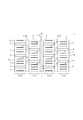
- FIG. 1 is a development view schematically showing a tread pattern of a pneumatic tire according to an embodiment of the present invention.
- the tire of this example has a plurality of tire circumferential main grooves 2 (2a, 2b, 2c) extending in the tire circumferential direction (three in the illustrated example) and a plurality of tires on the tread tread surface 1.
- a plurality of compartments are partitioned between the circumferential main grooves 2 adjacent to each other in the tire width direction, or by the circumferential main grooves 2 (2a, 2c) and the tread end TE.
- one circumferential main groove 2b is located on the tire equatorial plane CL
- the other circumferential main grooves 2a and 2c are one of the tire width directions with the tire equatorial plane CL as a boundary. It is located in one half and the other half.
- two land portions 3 are arranged in each tire width direction half portion.
- the number of the circumferential main grooves 2 is 3, but it may be 1 to 2 or 4 or more. Therefore, the number of land portions 3 can also be 2 to 3 or 5 or more.
- each land portion 3 has a plurality of width direction grooves 4 extending in the tire width direction, and is divided into a plurality of blocks 5 by the width direction grooves 4.
- all the land portions 3 are divided into blocks 5, but some of the land portions 3 may be ribbed land portions that are not completely divided by the width direction groove.
- the land portion 3 is divided in the tire circumferential direction by the width direction sipe, it is included in the rib-shaped land portion if it is not completely divided by the width direction groove. To do.
- a plurality of width direction sipes 6 extending in the tire width direction (three in each block 5 in the illustrated example) are provided in the block 5.
- the number of width direction sipes 6 may be one or more, and therefore may be one to two or four or more.
- the groove width of the circumferential main groove 2 depends on the number of the circumferential main grooves 2, so it is particularly important. It is not limited, but can be, for example, 5 to 25 mm. Similarly, the groove depth (maximum depth) of the circumferential main groove 2 is not particularly limited, but may be, for example, 6 to 18 mm.
- the circumferential main grooves 2 extend along the tire circumferential direction (without tilting), but at least one circumferential main groove 2 extends around the tire. It may be inclined and extended with respect to the direction, and in that case, it may be inclined and extended at an angle of, for example, 5 ° or less with respect to the tire circumferential direction. Further, in the illustrated example, all of the circumferential main grooves 2 extend straight in the tire circumferential direction, but at least one circumferential main groove 2 has a shape such as a zigzag shape or a curved shape. Is also good.
- the groove width of the width direction groove 4 (opening width (opening width measured perpendicular to the extending direction of the groove in a plan view)) is not particularly limited because it depends on the number of width direction grooves 4, but for example. It can be 1.0 to 1.5 mm.
- the groove depth (maximum depth) of the width direction groove 4 is not particularly limited, but may be, for example, 4 to 18 mm.
- each width direction groove 4 extends along the tire width direction (without tilting), but at least one width direction groove 4 extends at a slope with respect to the tire width direction.
- the tire extends at an inclination angle of 60 ° or less with respect to the tire width direction, and it is preferable that the tire extends at an inclination angle of 40 ° or less. Further, in the illustrated example, all of the width direction grooves 4 extend straight in the tire width direction, but at least one width direction groove 4 may have a bent portion.
- the sipe width of the width direction sipe 6 (opening width (opening width measured perpendicular to the extending direction of the groove in a plan view)) is not particularly limited because it depends on the number of width direction sipe 6, but for example. It can be 0.2 to 1.0 mm.
- the sipe depth (maximum depth) of the width direction sipe 6 is not particularly limited, but can be, for example, 4.0 to 18.0 mm.
- all of the width direction sipes 6 extend along the tire width direction (without tilting), but at least one width direction sipe 6 extends at an angle with respect to the tire width direction.
- the tire extends at an inclination angle of 60 ° or less with respect to the tire width direction, and it is preferable that the tire extends at an inclination angle of 40 ° or less.
- all of the width direction sipes 6 extend straight in the tire width direction, but at least one width direction sipes 6 may have a bent portion.
- both ends of the width direction sipe 6 are terminated in the block 5, but one or both ends may communicate with the circumferential main groove 2.
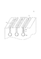
- FIG. 2 is a transparent perspective view of the block of FIG.
- a hard having a higher elastic modulus than the tread rubber.
- the rubber 7 is arranged.
- the hard rubber 7 is arranged so as to extend continuously over the wall surfaces on both sides and the bottom of the sipe that partition the width direction sipe 6.
- the elastic modulus of the tread rubber can be, for example, 2 to 4 MPa.
- the elastic modulus of the hard rubber 7 can be, for example, 3 to 6 MPa in a range larger than the elastic modulus of the tread rubber.
- the thickness of the hard rubber (the thickness measured in the normal direction of the groove wall, and the maximum thickness when the thickness changes) can be 0.2 to 1 mm.
- the thickness of the hard rubber is preferably substantially constant over the entire extending region thereof.
- the tread rubber is a foam rubber and the hard rubber is a non-foam rubber.
- the hard rubber for example, by providing an unvulcanized hard rubber film in advance at a position where the width direction sipe is provided before vulcanization, the hard rubber is used when the width direction sipe is formed by the blade. It can be provided so as to be located on the wall surface of the width direction sipe.
- FIG. 3 is a plan view of the block of FIG.
- Microfabrication 8 is applied to a region of the tread tread 1 that surrounds at least a part (all in the illustrated example) of the opening of the width direction sipe 6 to the tread tread 1.
- the microfabrication 8 is not shown for the sake of simplicity.
- the action and effect of the pneumatic tire of the present embodiment will be described.
- the block 5 is provided with one or more widthwise sipes 6, the water removal can be improved and the performance on ice can be improved.
- the hard rubber 7 having a higher elastic modulus than the tread rubber 7 Is arranged, it is possible to increase the block rigidity and improve the performance on snow.
- the hard rubber 7 is located at a position where the hard rubber 7 comes into contact with the road surface, the portion that becomes an edge when the tire rolls is particularly hard. It has been found that it is composed of rubber 7, and as a result, the grip performance on ice may be deteriorated. Therefore, in the pneumatic tire of the present embodiment, the region surrounding at least a part (all in the illustrated example) of the opening of the tread tread 1 to the tread tread 1 of the width direction sipe 6 is subjected to microfabrication 8. .. As a result, the ground contact property at the relevant location is improved, and the grip performance on ice and snow can be improved. As described above, according to the pneumatic tire of the present embodiment, both the performance on ice and the performance on snow can be achieved at the same time.
- the hard rubber is arranged over the entire wall surface that partitions the width direction sipes. This is because the block rigidity can be further increased to further improve the performance on snow.
- the region surrounding at least a part of the opening to the tread tread of the width direction sipe preferably surrounds the entire opening as shown in the illustrated example. This is because it is possible to secure a sufficient area for improving the ground contact property and further improve the grip performance on ice and snow. Further, it is preferable that the above-mentioned region includes a range from the opening of the width direction sipe to the tread tread to a position separated by 2 mm on both sides in the tire circumferential direction. This is because a region for improving the ground contact property can be sufficiently secured in the tire circumferential direction, and the grip performance on ice and snow can be further improved.
- the two regions adjacent to each other in the tire circumferential direction are separated by 1 mm or more and 10 mm or less in the tire circumferential direction (in FIG. 3). Is indicated by the distance B). More preferably, the two regions adjacent to each other in the tire circumferential direction can be separated by 1 mm or more and 5 mm or less in the tire circumferential direction.
- the distance B is 1 mm or more, the decrease in block rigidity can be suppressed, while when the distance B is 10 mm (more preferably 5 mm) or less, the edge pressure can be sufficiently secured. Because.
- the separated distance changes in the tire width direction, it means the minimum separated distance.
- the length in the tire circumferential direction of the above region is set to A (mm), and the length of the two adjacent tire circumferential directions in the tire circumferential direction is defined as A (mm).
- the separation distance is B (mm)
- the ratio A / B is 0.1 ⁇ A / B ⁇ 6 It is preferable to satisfy.
- the ratio A / B is 0.1 or more, the grip can be effectively improved by fine processing, while when the ratio A / B is 6 or less, the grip between adjacent sipes can be effectively exhibited. This is because the occurrence of abnormal wear can be suppressed.
- the length A changes in the tire width direction it means the minimum length.
- the separation distance B changes in the tire width direction it means the minimum separation distance.
- the width direction sipe is terminated in the block, and the region exists up to a position separated from the end by 2 mm or more in the tire width direction. This is because a region for improving the ground contact property can be sufficiently secured in the tire width direction, and the grip performance on ice and snow can be further improved.
- the microfabrication is preferably a process in which the surface roughness Ra of the above region is 10 to 500 ⁇ m.
- the surface roughness Ra of the above region is 10 to 500 ⁇ m.
- the surface area of the region is increased, while by setting the surface roughness Ra of the region to 500 ⁇ m or less, the actual contact area with respect to the surface area of the region is increased. This is because it can be increased to further improve the grip performance on ice and snow.
- the surface roughness Ra of the above region is more preferably 25 to 400 ⁇ m, further preferably 50 to 200 ⁇ m.
- the surface roughness Ra of the width direction sipe on one side in the tire circumferential direction is the surface roughness Ra of the region of the width direction sipes on the other side of the tire circumferential direction. Larger is preferred.
- improving water removal is advantageous for grip performance on ice and snow
- improving ground contact is advantageous for grip performance on ice and snow. This is because when one side in the circumferential direction is the stepping side of the block, the performance on ice and snow can be effectively improved.
- the surface roughness Ra of the width direction sipe on the stepping side of the block is the surface roughness Ra of the width direction sipe 6 on the kicking side of the block. It is preferably larger than Ra. Further, for the same reason, when the block has a plurality of width direction sipes, it is preferable to maximize the surface roughness Ra of the region of the width direction sipes located on one side (stepping side) in the tire circumferential direction. When the block has three or more width direction sipes, the surface roughness Ra of the above region of the width direction sipes 6 is directed from one side in the tire circumferential direction (stepping side) to the other side in the tire circumferential direction (kicking side). It is also preferable that On the other hand, it is not necessary to make the surface roughness Ra of the above region different between the width direction sipes, and it can be the same.
- the microfabrication is preferably a process in which the kurtosis Rku in the above region is 2 to 6.
- the kurtosis Rku By setting the kurtosis Rku to 2 or more, it is possible to efficiently improve the ground contact property by microfabrication, while by setting the kurtosis Rku to 6 or less, abnormal wear and grip due to excessive surface roughness can be exhibited. This is because the decrease in the amount of For the same reason, it is more preferable that the kurtosis Rku of the above region is 3 to 5.
- the microfabricated region is rectangular in a plan view, but the present invention is not limited to this case, and various shapes such as a partially rounded shape can be used.
- the width direction sipe when inclined with respect to the tire width direction, it may have a parallel quadrilateral shape in a plan view.
- the above microfabrication can be formed by any known method, for example, by projecting a blast material or the like.
- the above hard rubber is arranged and microfabrication is performed on the above region.
- the width direction sipes is any one of the plurality of width direction sipes. Any of the above width direction sipes may be used.
- the rotation direction is specified, hard rubber is arranged at least in the width direction sipe located on the most kicking side of the block, and the above region is microfabricated.
- each width direction sipe 6 has a constant sipe width (width measured parallel to the tread tread 1 in cross-sectional view) (equal to the opening width at the tread tread 1) on the tread tread 1 side. It has a sipe width constant portion 6a, and has a widening portion 6b on the sipe bottom side where the sipe width is larger than that on the tread tread 1 side. In the illustrated example, the widening portion 6b has a substantially circular cross section. As described above, the width direction sipe preferably has a widening portion on the groove bottom side in which the sipe width is larger than that on the tread tread side.
- the block piece (the portion where the block is partitioned by the width direction sipes) is likely to fall down, the edge pressure can be improved, and the grip performance on ice and snow can be further improved.
- the portion outside the widening portion 6b in the tire radial direction is a sipe width constant portion 6a in which the sipe width is constant, but this portion may be a portion in which the sipe width changes.
- the sipe width of the constant sipe width portion 6a is not particularly limited, but can be, for example, 0.2 to 1.0 mm.
- the maximum width of the widening portion 6b is not particularly limited, but can be, for example, 1.2 to 6.0 mm.
- the extending length of the constant sipe width portion 6a in the depth direction is not particularly limited, but may be, for example, 2.0 to 12 mm.
- the extending length of the widened portion 6b in the depth direction is not particularly limited, but may be, for example, 2.5 to 11.0 mm.
- the block has a plurality of width direction sipes and the width of the widening portion on one side in the tire circumferential direction is larger than the width of the widening portion on the other side in the tire circumferential direction. Since the kicking side of the block has a particularly large contribution to the edge effect, when one side in the tire circumferential direction is set as the kicking side, the block piece on the kicking side (the part where the block is partitioned by the width direction sipes) is likely to fall down. This is because the grip performance on ice and snow can be further improved particularly effectively.
- the width of the widening portion gradually decreases from one side in the tire circumferential direction to the other side in the tire circumferential direction.
- the rotation direction is specified, and it is preferable that the width of the widening portion on the kicking side of the block is larger than the width of the widening portion on the stepping side of the block.
- the width of the widening portion gradually decreases from the kicking side of the block toward the stepping side of the block.
- the pneumatic tire of the present invention is not particularly limited, but is particularly preferably used for a studless tire.
Abstract
This pneumatic tire comprises, in a tread surface, a plurality of circumferential main grooves that extend in the tire circumferential direction, and a plurality of lands that are demarcated between circumferential main grooves, of the plurality of circumferential main grooves, that are adjacent in the tire width direction or by the circumferential main grooves and a tread edge. The lands each include a plurality of width-direction grooves that extend in the tire width direction and are demarcated into a plurality of blocks by the width-direction grooves. The blocks each include at least one width-direction sipe that extends in the tire width direction; hard rubber with an elastic modulus greater than that of tread rubber is disposed in a region in the tire radial direction of a wall surface that demarcates the width-direction sipe, including at least an opening section open to the tread surface; and microfabrication is applied to a region of the tread surface that surrounds at least part of the opening section of the width-direction sipe open to the tread surface.
Description
本発明は、空気入りタイヤに関するものである。
The present invention relates to a pneumatic tire.
冬用の空気入りタイヤにおいては、氷上性能を向上させるための種々の工夫がなされている。例えば、トレッドゴムに発泡ゴムを用いて除水性を向上させることや、トレッド踏面にサイプを形成して水膜を除去することが行われている(例えば、特許文献1)。
In the winter pneumatic tires, various measures have been taken to improve the performance on ice. For example, foam rubber is used for the tread rubber to improve water removal, and a sipe is formed on the tread tread to remove a water film (for example, Patent Document 1).
一方で、冬用の空気入りタイヤにおいては、雪上性能を向上させることも求められている。しかしながら、トレッドゴムに発泡ゴム等の軟らかいゴムを用いた場合には、幅方向サイプの開口部が雪上路面に接した際に、十分なエッジ圧を得ることができずに雪上性能が低下してしまう場合があった。このように、氷上性能と雪上性能とを両立させることは困難であった。
On the other hand, it is also required to improve the performance on snow in pneumatic tires for winter. However, when a soft rubber such as foam rubber is used for the tread rubber, when the opening of the width direction sipe comes into contact with the road surface on snow, sufficient edge pressure cannot be obtained and the performance on snow deteriorates. There was a case that it ended up. In this way, it was difficult to achieve both performance on ice and performance on snow.
そこで、本発明は、氷上性能と雪上性能とを両立させた空気入りタイヤを提供することを目的とする。
Therefore, an object of the present invention is to provide a pneumatic tire that has both performance on ice and performance on snow.
本発明の要旨構成は、以下の通りである。
本発明の空気入りタイヤは、トレッド踏面に、タイヤ周方向に延びる複数本の周方向主溝と、前記複数本の周方向主溝のうちタイヤ幅方向に隣接する前記周方向主溝間に、又は、前記周方向主溝とトレッド端とにより、区画される複数の陸部と、を有し、
前記陸部は、タイヤ幅方向に延びる複数本の幅方向溝を有し、前記幅方向溝により複数のブロックに区画され、
前記ブロック内に、タイヤ幅方向に延びる1本以上の幅方向サイプを有し、
前記幅方向サイプを区画する壁面の少なくとも前記トレッド踏面への開口部を含むタイヤ径方向領域に、トレッドゴムより弾性率の大きい硬ゴムが配置され、
前記トレッド踏面の、前記幅方向サイプの前記トレッド踏面への開口部の少なくとも一部を囲む領域に、微細加工が施されている。
ここで、「トレッド踏面」とは、空気入りタイヤを適用リムに装着し、規定内圧を充填して、最大負荷荷重を負荷した際に路面と接地することとなるトレッド表面の、タイヤ周方向全域にわたる面をいう。
また、「周方向主溝」とは、タイヤ周方向に延び、空気入りタイヤを適用リムに装着し、規定内圧を充填し、無負荷とした状態での、上記トレッド踏面における開口幅が、1.5mm以上のものをいう。
また、「トレッド端」とは、上記トレッド踏面のタイヤ幅方向両側の最外側点をいう。
また、「幅方向溝」とは、タイヤ幅方向に延び、空気入りタイヤを適用リムに装着し、規定内圧を充填し、無負荷とした状態での、上記トレッド踏面における開口幅が、1.0mm以上のものをいう。
また、「幅方向サイプ」とは、タイヤ幅方向に延び、空気入りタイヤを適用リムに装着し、規定内圧を充填し、無負荷とした状態での、上記トレッド踏面における開口幅が、1.0mm未満のものをいう。
また、「弾性率」とは、JIS K 6251に準拠して引張試験を行い、25%伸長時の引張応力を測定した値(M(モジュラス)25)を採用した。
本明細書において、「適用リム」とは、タイヤが生産され、使用される地域に有効な産業規格であって、日本ではJATMA(日本自動車タイヤ協会)のJATMA YEAR BOOK、欧州ではETRTO(The European Tyre and Rim Technical Organisation)のSTANDARDS MANUAL、米国ではTRA(The Tire and Rim Association,Inc.)のYEAR BOOK等に記載されているまたは将来的に記載される、適用サイズにおける標準リム(ETRTOのSTANDARDS MANUALではMeasuring Rim、TRAのYEAR BOOKではDesign Rim)を指す(即ち、上記の「リム」には、現行サイズに加えて将来的に上記産業規格に含まれ得るサイズも含む。「将来的に記載されるサイズ」の例としては、ETRTO 2013年度版において「FUTURE DEVELOPMENTS」として記載されているサイズを挙げることができる。)が、上記産業規格に記載のないサイズの場合は、タイヤのビード幅に対応した幅のリムをいう。
また、「規定内圧」とは、上記JATMA等に記載されている、適用サイズ・プライレーティングにおける単輪の最大負荷能力に対応する空気圧(最高空気圧)を指し、上記産業規格に記載のないサイズの場合は、「規定内圧」は、タイヤを装着する車両毎に規定される最大負荷能力に対応する空気圧(最高空気圧)をいうものとする。
また、「最大負荷荷重」とは、上記最大負荷能力に対応する荷重をいうものとする。 The gist structure of the present invention is as follows.
In the pneumatic tire of the present invention, on the tread tread, between a plurality of circumferential main grooves extending in the tire circumferential direction and the circumferential main grooves adjacent to the tire width direction among the plurality of circumferential main grooves. Alternatively, it has a plurality of land portions partitioned by the circumferential main groove and the tread end.
The land portion has a plurality of widthwise grooves extending in the tire width direction, and is divided into a plurality of blocks by the widthwise grooves.
The block has one or more widthwise sipes extending in the tire width direction.
A hard rubber having a modulus of elasticity higher than that of the tread rubber is arranged in a tire radial region including at least an opening to the tread tread on the wall surface that partitions the width direction sipe.
A region of the tread tread that surrounds at least a portion of the opening of the widthwise sipe to the tread tread is finely processed.
Here, the "tread tread" is the entire tire circumferential direction of the tread surface that comes into contact with the road surface when a pneumatic tire is attached to the applicable rim, the specified internal pressure is applied, and the maximum load is applied. It refers to the aspect that extends.
Further, the "circumferential main groove" means that the opening width of the tread tread is 1 when the tire extends in the circumferential direction, the pneumatic tire is attached to the applicable rim, the specified internal pressure is applied, and no load is applied. .5 mm or more.
The "tread end" refers to the outermost points on both sides of the tread tread in the tire width direction.
Further, the "width direction groove" means that the opening width of the tread tread is 1. It means a tire of 0 mm or more.
Further, the "width direction sipe" means that the opening width of the tread tread is 1. Those less than 0 mm.
As the "elasticity", a value (M (modulus) 25) obtained by performing a tensile test in accordance with JIS K 6251 and measuring the tensile stress at the time of 25% elongation was adopted.
In the present specification, the "applicable rim" is an industrial standard effective in the area where the tire is produced and used. In Japan, JATMA (Japan Automobile Tire Association) JATMA YEAR BOOK, and in Europe, ETRTO (The European). STANDARDS MANUAL of Tire and Rim Technical Organization), YEAR BOOK of TRA (The Tire and Rim Association, Inc.) in the United States, etc. Refers to Tireing Rim, Design Rim in TRA's YEAR BOOK (ie, the "rim" above includes sizes that may be included in the industry standard in the future in addition to the current size. As an example of "size", the size described as "FUTURE DEVELOPMENTS" in the ETRTO 2013 edition can be mentioned.) However, if the size is not described in the above industrial standard, it corresponds to the bead width of the tire. A rim with a wide width.
In addition, the "specified internal pressure" refers to the air pressure (maximum air pressure) corresponding to the maximum load capacity of a single wheel in the applicable size and ply rating described in the above JATMA, etc., and is of a size not described in the above industrial standard. In this case, the "specified internal pressure" shall mean the air pressure (maximum air pressure) corresponding to the maximum load capacity specified for each vehicle equipped with tires.
Further, the "maximum load" means a load corresponding to the above maximum load capacity.
本明細書において、表面粗さRaとは、JIS B 0601に基づいて計測した中心線平均粗さをいう。また、尖度Rkuとは、ISO 25178に基づいて算出される表面粗さの尖り度をいう。
In this specification, the surface roughness Ra means the center line average roughness measured based on JIS B 0601. Further, the kurtosis Rku means the kurtosis of the surface roughness calculated based on ISO 25178.
本発明によれば、氷上性能と雪上性能とを両立させた空気入りタイヤを提供することができる。
According to the present invention, it is possible to provide a pneumatic tire that has both performance on ice and performance on snow.
以下、本発明の実施形態について、図面を参照して詳細に例示説明する。
ここで、空気入りタイヤ(以下、単にタイヤとも称する)の内部構造等については、従来のものと同様の構造とすることができる。一例としては、該タイヤは、一対のビード部と、該一対のビード部に連なる一対のサイドウォール部と、該一対のサイドウォール部間に配置されたトレッド部とを有するものとすることができる。また、該タイヤは、一対のビード部間をトロイダル状に跨るカーカスと、該カーカスのクラウン部のタイヤ径方向外側に配置されたベルトと、を有するものとすることができる。
以下、特に断りのない限り、寸法等は、タイヤを適用リムに装着し、規定内圧を充填し、無負荷状態とした際の寸法等を指す。 Hereinafter, embodiments of the present invention will be described in detail with reference to the drawings.
Here, the internal structure and the like of the pneumatic tire (hereinafter, also simply referred to as a tire) can be the same as that of the conventional one. As an example, the tire may have a pair of bead portions, a pair of sidewall portions connected to the pair of bead portions, and a tread portion arranged between the pair of sidewall portions. .. Further, the tire may have a carcass straddling the pair of bead portions in a toroidal manner, and a belt arranged on the outer side of the crown portion of the carcass in the tire radial direction.
Hereinafter, unless otherwise specified, the dimensions and the like refer to the dimensions and the like when the tire is mounted on the applicable rim, the specified internal pressure is filled, and the load is not applied.
図1は、本発明の一実施形態にかかる空気入りタイヤのトレッドパターンを模式的に示す展開図である。
FIG. 1 is a development view schematically showing a tread pattern of a pneumatic tire according to an embodiment of the present invention.
図1に示すように、本例のタイヤは、トレッド踏面1に、タイヤ周方向に延びる複数本(図示例では3本)の周方向主溝2(2a、2b、2c)と、複数本の周方向主溝2のうちタイヤ幅方向に隣接する周方向主溝2間に、又は、周方向主溝2(2a、2c)とトレッド端TEとにより、区画される複数(図示例では4つ)の陸部3(3a、3b、3c、3d)と、を有している。この例では、1つの周方向主溝2bは、タイヤ赤道面CL上に位置しており、他の周方向主溝2a、2cは、それぞれタイヤ赤道面CLを境界としたタイヤ幅方向の一方の半部、他方の半部に位置している。そして、この例では、各タイヤ幅方向半部に2つずつの陸部3が配置されている。図1に示した例では、周方向主溝2の本数は、3本であるが、1~2本又は4本以上とすることもできる。従って、陸部3の個数も、2~3つ又は5つ以上とすることができる。
As shown in FIG. 1, the tire of this example has a plurality of tire circumferential main grooves 2 (2a, 2b, 2c) extending in the tire circumferential direction (three in the illustrated example) and a plurality of tires on the tread tread surface 1. Of the circumferential main grooves 2, a plurality of compartments (four in the illustrated example) are partitioned between the circumferential main grooves 2 adjacent to each other in the tire width direction, or by the circumferential main grooves 2 (2a, 2c) and the tread end TE. ) With the land portion 3 (3a, 3b, 3c, 3d). In this example, one circumferential main groove 2b is located on the tire equatorial plane CL, and the other circumferential main grooves 2a and 2c are one of the tire width directions with the tire equatorial plane CL as a boundary. It is located in one half and the other half. Then, in this example, two land portions 3 are arranged in each tire width direction half portion. In the example shown in FIG. 1, the number of the circumferential main grooves 2 is 3, but it may be 1 to 2 or 4 or more. Therefore, the number of land portions 3 can also be 2 to 3 or 5 or more.
また、各陸部3は、タイヤ幅方向に延びる複数本の幅方向溝4を有し、幅方向溝4により複数のブロック5に区画されている。なお、本例では、全ての陸部3がブロック5に区画されているが、一部の陸部3を幅方向溝で完全に分断されていないリブ状陸部とすることもできる。なお、本明細書においては、幅方向サイプにより陸部3がタイヤ周方向に分断されている場合であっても、幅方向溝で完全に分断されていなければ、リブ状陸部に含めるものとする。
Further, each land portion 3 has a plurality of width direction grooves 4 extending in the tire width direction, and is divided into a plurality of blocks 5 by the width direction grooves 4. In this example, all the land portions 3 are divided into blocks 5, but some of the land portions 3 may be ribbed land portions that are not completely divided by the width direction groove. In this specification, even if the land portion 3 is divided in the tire circumferential direction by the width direction sipe, it is included in the rib-shaped land portion if it is not completely divided by the width direction groove. To do.
また、本実施形態では、図1に示すように、ブロック5内に、タイヤ幅方向に延びる複数本(図示例では各ブロック5に3本ずつ)の幅方向サイプ6を有している。なお、幅方向サイプ6の本数は、1本以上であれば良く、従って1~2本又は4本以上とすることもできる。
Further, in the present embodiment, as shown in FIG. 1, a plurality of width direction sipes 6 extending in the tire width direction (three in each block 5 in the illustrated example) are provided in the block 5. The number of width direction sipes 6 may be one or more, and therefore may be one to two or four or more.
ここで、周方向主溝2の溝幅(開口幅(平面視において、溝の延在方向に対して垂直に測った開口幅))は、周方向主溝2の本数にもよるため特には限定されないが、例えば5~25mmとすることができる。同様に、周方向主溝2の溝深さ(最大深さ)は、特には限定されないが、例えば6~18mmとすることができる。
Here, the groove width of the circumferential main groove 2 (opening width (opening width measured perpendicular to the extending direction of the groove in a plan view)) depends on the number of the circumferential main grooves 2, so it is particularly important. It is not limited, but can be, for example, 5 to 25 mm. Similarly, the groove depth (maximum depth) of the circumferential main groove 2 is not particularly limited, but may be, for example, 6 to 18 mm.
図示例では、トレッド踏面1の平面視において、周方向主溝2は、いずれも、タイヤ周方向に沿って(傾斜せずに)延びているが、少なくとも1つの周方向主溝2がタイヤ周方向に対して傾斜して延びていても良く、その場合、タイヤ周方向に対して、例えば5°以下の角度で傾斜して延びるものとすることができる。また、図示例では、周方向主溝2は、いずれも、タイヤ周方向に真っ直ぐ延びているが、少なくとも1本の周方向主溝2が、ジグザグ状、湾曲状などの形状を有していても良い。
In the illustrated example, in the plan view of the tread tread 1, the circumferential main grooves 2 extend along the tire circumferential direction (without tilting), but at least one circumferential main groove 2 extends around the tire. It may be inclined and extended with respect to the direction, and in that case, it may be inclined and extended at an angle of, for example, 5 ° or less with respect to the tire circumferential direction. Further, in the illustrated example, all of the circumferential main grooves 2 extend straight in the tire circumferential direction, but at least one circumferential main groove 2 has a shape such as a zigzag shape or a curved shape. Is also good.
幅方向溝4の溝幅(開口幅(平面視において、溝の延在方向に対して垂直に測った開口幅))は、幅方向溝4の本数にもよるため特には限定されないが、例えば1.0~1.5mmとすることができる。同様に、幅方向溝4の溝深さ(最大深さ)は、特には限定されないが、例えば4~18mmとすることができる。
なお、図示例では、いずれの幅方向溝4も、タイヤ幅方向に沿って(傾斜せずに)延びているが、少なくとも1本の幅方向溝4がタイヤ幅方向に対して傾斜して延びていても良く、この場合、タイヤ幅方向に対して60°以下の傾斜角度で傾斜して延びていることが好ましく、また、40°以下の傾斜角度で傾斜して延びていることが好ましい。また、図示例では、幅方向溝4は、いずれも、タイヤ幅方向に真っ直ぐ延びているが、少なくとも1本の幅方向溝4が、屈曲した部分を有していても良い。 The groove width of the width direction groove 4 (opening width (opening width measured perpendicular to the extending direction of the groove in a plan view)) is not particularly limited because it depends on the number ofwidth direction grooves 4, but for example. It can be 1.0 to 1.5 mm. Similarly, the groove depth (maximum depth) of the width direction groove 4 is not particularly limited, but may be, for example, 4 to 18 mm.
In the illustrated example, eachwidth direction groove 4 extends along the tire width direction (without tilting), but at least one width direction groove 4 extends at a slope with respect to the tire width direction. In this case, it is preferable that the tire extends at an inclination angle of 60 ° or less with respect to the tire width direction, and it is preferable that the tire extends at an inclination angle of 40 ° or less. Further, in the illustrated example, all of the width direction grooves 4 extend straight in the tire width direction, but at least one width direction groove 4 may have a bent portion.
なお、図示例では、いずれの幅方向溝4も、タイヤ幅方向に沿って(傾斜せずに)延びているが、少なくとも1本の幅方向溝4がタイヤ幅方向に対して傾斜して延びていても良く、この場合、タイヤ幅方向に対して60°以下の傾斜角度で傾斜して延びていることが好ましく、また、40°以下の傾斜角度で傾斜して延びていることが好ましい。また、図示例では、幅方向溝4は、いずれも、タイヤ幅方向に真っ直ぐ延びているが、少なくとも1本の幅方向溝4が、屈曲した部分を有していても良い。 The groove width of the width direction groove 4 (opening width (opening width measured perpendicular to the extending direction of the groove in a plan view)) is not particularly limited because it depends on the number of
In the illustrated example, each
幅方向サイプ6のサイプ幅(開口幅(平面視において、溝の延在方向に対して垂直に測った開口幅))は、幅方向サイプ6の本数にもよるため特には限定されないが、例えば0.2~1.0mmとすることができる。同様に、幅方向サイプ6のサイプ深さ(最大深さ)は、特には限定されないが、例えば4.0~18.0mmとすることができる。
なお、図示例では、いずれの幅方向サイプ6も、タイヤ幅方向に沿って(傾斜せずに)延びているが、少なくとも1本の幅方向サイプ6がタイヤ幅方向に対して傾斜して延びていても良く、この場合、タイヤ幅方向に対して60°以下の傾斜角度で傾斜して延びていることが好ましく、また、40°以下の傾斜角度で傾斜して延びていることが好ましい。また、図示例では、幅方向サイプ6は、いずれも、タイヤ幅方向に真っ直ぐ延びているが、少なくとも1本の幅方向サイプ6が、屈曲した部分を有していても良い。
図示例では、幅方向サイプ6は、両端がブロック5内で終端しているが、一方又は両方の端が、周方向主溝2に連通していても良い。 The sipe width of the width direction sipe 6 (opening width (opening width measured perpendicular to the extending direction of the groove in a plan view)) is not particularly limited because it depends on the number ofwidth direction sipe 6, but for example. It can be 0.2 to 1.0 mm. Similarly, the sipe depth (maximum depth) of the width direction sipe 6 is not particularly limited, but can be, for example, 4.0 to 18.0 mm.
In the illustrated example, all of thewidth direction sipes 6 extend along the tire width direction (without tilting), but at least one width direction sipe 6 extends at an angle with respect to the tire width direction. In this case, it is preferable that the tire extends at an inclination angle of 60 ° or less with respect to the tire width direction, and it is preferable that the tire extends at an inclination angle of 40 ° or less. Further, in the illustrated example, all of the width direction sipes 6 extend straight in the tire width direction, but at least one width direction sipes 6 may have a bent portion.
In the illustrated example, both ends of thewidth direction sipe 6 are terminated in the block 5, but one or both ends may communicate with the circumferential main groove 2.
なお、図示例では、いずれの幅方向サイプ6も、タイヤ幅方向に沿って(傾斜せずに)延びているが、少なくとも1本の幅方向サイプ6がタイヤ幅方向に対して傾斜して延びていても良く、この場合、タイヤ幅方向に対して60°以下の傾斜角度で傾斜して延びていることが好ましく、また、40°以下の傾斜角度で傾斜して延びていることが好ましい。また、図示例では、幅方向サイプ6は、いずれも、タイヤ幅方向に真っ直ぐ延びているが、少なくとも1本の幅方向サイプ6が、屈曲した部分を有していても良い。
図示例では、幅方向サイプ6は、両端がブロック5内で終端しているが、一方又は両方の端が、周方向主溝2に連通していても良い。 The sipe width of the width direction sipe 6 (opening width (opening width measured perpendicular to the extending direction of the groove in a plan view)) is not particularly limited because it depends on the number of
In the illustrated example, all of the
In the illustrated example, both ends of the
図2は、図1のブロックの透過斜視図である。図2に示すように、幅方向サイプ6を区画する壁面の少なくともトレッド踏面1への開口部を含むタイヤ径方向領域に(本例では、壁面の全域にわたって)、トレッドゴムより弾性率の大きい硬ゴム7が配置されている。具体的には、図示例では、硬ゴム7は、幅方向サイプ6を区画する両側の壁面及びサイプ底にわたって連続的に延在するように配置されている。
FIG. 2 is a transparent perspective view of the block of FIG. As shown in FIG. 2, in the tire radial region including at least the opening to the tread tread 1 of the wall surface partitioning the width direction sipe 6 (in this example, over the entire wall surface), a hard having a higher elastic modulus than the tread rubber. The rubber 7 is arranged. Specifically, in the illustrated example, the hard rubber 7 is arranged so as to extend continuously over the wall surfaces on both sides and the bottom of the sipe that partition the width direction sipe 6.
トレッドゴムの弾性率は、例えば、2~4MPaとすることができる。また、硬ゴム7の弾性率は、トレッドゴムの弾性率よりも大きい範囲で、例えば3~6MPaとすることができる。硬ゴムの厚さ(溝壁の法線方向に測った厚さであり、厚さが変化する場合は最大厚さ)は、0.2~1mmとすることができる。硬ゴムの厚さは、その延在領域全体にわたって略一定とすることが好ましい。特には限定されないが、トレッドゴムを発泡ゴムとし、硬ゴムを非発泡ゴムとすることが好ましい。
なお、硬ゴムは、一例としては、加硫前に幅方向サイプを設ける位置に、予め未加硫の硬ゴムの膜を設けることにより、ブレードにより幅方向サイプを形成する際に、硬ゴムを幅方向サイプの壁面に位置させるようにして設けることができる。 The elastic modulus of the tread rubber can be, for example, 2 to 4 MPa. The elastic modulus of thehard rubber 7 can be, for example, 3 to 6 MPa in a range larger than the elastic modulus of the tread rubber. The thickness of the hard rubber (the thickness measured in the normal direction of the groove wall, and the maximum thickness when the thickness changes) can be 0.2 to 1 mm. The thickness of the hard rubber is preferably substantially constant over the entire extending region thereof. Although not particularly limited, it is preferable that the tread rubber is a foam rubber and the hard rubber is a non-foam rubber.
As for the hard rubber, for example, by providing an unvulcanized hard rubber film in advance at a position where the width direction sipe is provided before vulcanization, the hard rubber is used when the width direction sipe is formed by the blade. It can be provided so as to be located on the wall surface of the width direction sipe.
なお、硬ゴムは、一例としては、加硫前に幅方向サイプを設ける位置に、予め未加硫の硬ゴムの膜を設けることにより、ブレードにより幅方向サイプを形成する際に、硬ゴムを幅方向サイプの壁面に位置させるようにして設けることができる。 The elastic modulus of the tread rubber can be, for example, 2 to 4 MPa. The elastic modulus of the
As for the hard rubber, for example, by providing an unvulcanized hard rubber film in advance at a position where the width direction sipe is provided before vulcanization, the hard rubber is used when the width direction sipe is formed by the blade. It can be provided so as to be located on the wall surface of the width direction sipe.
図3は、図1のブロックの平面図である。トレッド踏面1の、幅方向サイプ6のトレッド踏面1への開口部の少なくとも一部(図示例では全部)を囲む領域に、微細加工8が施されている。なお、図1においては、簡単のために、微細加工8の図示は省略している。
以下、本実施形態の空気入りタイヤの作用効果について説明する。 FIG. 3 is a plan view of the block of FIG.Microfabrication 8 is applied to a region of the tread tread 1 that surrounds at least a part (all in the illustrated example) of the opening of the width direction sipe 6 to the tread tread 1. In FIG. 1, the microfabrication 8 is not shown for the sake of simplicity.
Hereinafter, the action and effect of the pneumatic tire of the present embodiment will be described.
以下、本実施形態の空気入りタイヤの作用効果について説明する。 FIG. 3 is a plan view of the block of FIG.
Hereinafter, the action and effect of the pneumatic tire of the present embodiment will be described.
本実施形態の空気入りタイヤによれば、まず、ブロック5に1本以上の幅方向サイプ6を設けているため、除水性を向上させて、氷上性能を向上させることができる。一方で、幅方向サイプ6の壁面を区画する壁面の少なくともトレッド踏面1への開口部を含むタイヤ径方向領域に(本例では、壁面の全域にわたって)、トレッドゴムより弾性率の大きい硬ゴム7が配置されているため、ブロック剛性を高めて雪上性能を向上させることもできる。
一方、本発明者が鋭意検討したところ、上記のような硬ゴム7を配置した構成においては、路面と接地する箇所に硬ゴム7が位置するため、特にタイヤ転動時にエッジとなる箇所が硬ゴム7で構成され、その結果、氷上グリップ性能が低下する場合があることが判明した。
そこで、本実施形態の空気入りタイヤでは、トレッド踏面1の、幅方向サイプ6のトレッド踏面1への開口部の少なくとも一部(図示例では全部)を囲む領域に、微細加工8を施している。これにより、当該箇所での接地性が向上し、氷上及び雪上グリップ性能を向上させることができる。
以上のように、本実施形態の空気入りタイヤによれば、氷上性能と雪上性能とを両立させることができる。 According to the pneumatic tire of the present embodiment, first, since theblock 5 is provided with one or more widthwise sipes 6, the water removal can be improved and the performance on ice can be improved. On the other hand, in the tire radial region including at least the opening to the tread tread 1 of the wall surface partitioning the wall surface of the width direction sipe 6 (in this example, over the entire wall surface), the hard rubber 7 having a higher elastic modulus than the tread rubber 7 Is arranged, it is possible to increase the block rigidity and improve the performance on snow.
On the other hand, as a result of diligent studies by the present inventor, in the configuration in which thehard rubber 7 is arranged as described above, since the hard rubber 7 is located at a position where the hard rubber 7 comes into contact with the road surface, the portion that becomes an edge when the tire rolls is particularly hard. It has been found that it is composed of rubber 7, and as a result, the grip performance on ice may be deteriorated.
Therefore, in the pneumatic tire of the present embodiment, the region surrounding at least a part (all in the illustrated example) of the opening of thetread tread 1 to the tread tread 1 of the width direction sipe 6 is subjected to microfabrication 8. .. As a result, the ground contact property at the relevant location is improved, and the grip performance on ice and snow can be improved.
As described above, according to the pneumatic tire of the present embodiment, both the performance on ice and the performance on snow can be achieved at the same time.
一方、本発明者が鋭意検討したところ、上記のような硬ゴム7を配置した構成においては、路面と接地する箇所に硬ゴム7が位置するため、特にタイヤ転動時にエッジとなる箇所が硬ゴム7で構成され、その結果、氷上グリップ性能が低下する場合があることが判明した。
そこで、本実施形態の空気入りタイヤでは、トレッド踏面1の、幅方向サイプ6のトレッド踏面1への開口部の少なくとも一部(図示例では全部)を囲む領域に、微細加工8を施している。これにより、当該箇所での接地性が向上し、氷上及び雪上グリップ性能を向上させることができる。
以上のように、本実施形態の空気入りタイヤによれば、氷上性能と雪上性能とを両立させることができる。 According to the pneumatic tire of the present embodiment, first, since the
On the other hand, as a result of diligent studies by the present inventor, in the configuration in which the
Therefore, in the pneumatic tire of the present embodiment, the region surrounding at least a part (all in the illustrated example) of the opening of the
As described above, according to the pneumatic tire of the present embodiment, both the performance on ice and the performance on snow can be achieved at the same time.
ここで、硬ゴムは、幅方向サイプを区画する壁面の全域にわたって配置されていることが好ましい。ブロック剛性をさらに高めて雪上性能をさらに向上させることができるからである。
Here, it is preferable that the hard rubber is arranged over the entire wall surface that partitions the width direction sipes. This is because the block rigidity can be further increased to further improve the performance on snow.
幅方向サイプのトレッド踏面への開口部の少なくとも一部を囲む領域は、図示例のように、該開口部の全部を囲むことが好ましい。接地性を向上させる領域を十分に確保して、氷上及び雪上グリップ性能をより一層向上させることができるからである。
また、上記領域は、幅方向サイプのトレッド踏面への開口部からタイヤ周方向両側に2mmずつ離間した位置までの範囲を含んでいることが好ましい。接地性を向上させる領域をタイヤ周方向に十分に確保して、氷上及び雪上グリップ性能をより一層向上させることができるからである。 The region surrounding at least a part of the opening to the tread tread of the width direction sipe preferably surrounds the entire opening as shown in the illustrated example. This is because it is possible to secure a sufficient area for improving the ground contact property and further improve the grip performance on ice and snow.
Further, it is preferable that the above-mentioned region includes a range from the opening of the width direction sipe to the tread tread to a position separated by 2 mm on both sides in the tire circumferential direction. This is because a region for improving the ground contact property can be sufficiently secured in the tire circumferential direction, and the grip performance on ice and snow can be further improved.
また、図示例のように、ブロックが幅方向サイプを複数本有する場合、タイヤ周方向に隣接する2つの上記領域は、タイヤ周方向に1mm以上10mm以下離間していることが好ましい(図3においては、距離Bで示している)。さらに好ましくは、タイヤ周方向に隣接する2つの上記領域は、タイヤ周方向に1mm以上5mm以下離間することができる。距離Bが1mm以上であることにより、ブロック剛性の低下を抑制することができ、一方で、距離Bが10mm(さらに好ましくは5mm)以下であることにより、エッジ圧を十分に確保することができるからである。なお、離間している距離がタイヤ幅方向に変化する場合には、最小離間距離をいうものとする。
Further, as shown in the illustrated example, when the block has a plurality of sipes in the width direction, it is preferable that the two regions adjacent to each other in the tire circumferential direction are separated by 1 mm or more and 10 mm or less in the tire circumferential direction (in FIG. 3). Is indicated by the distance B). More preferably, the two regions adjacent to each other in the tire circumferential direction can be separated by 1 mm or more and 5 mm or less in the tire circumferential direction. When the distance B is 1 mm or more, the decrease in block rigidity can be suppressed, while when the distance B is 10 mm (more preferably 5 mm) or less, the edge pressure can be sufficiently secured. Because. When the separated distance changes in the tire width direction, it means the minimum separated distance.
また、図示例のように、ブロックが幅方向サイプを複数本有する場合、上記領域のタイヤ周方向の長さをA(mm)とし、タイヤ周方向に隣接する2つの上記領域のタイヤ周方向の離間距離をB(mm)とするとき、比A/Bは、
0.1≦A/B≦6
を満たすことが好ましい。
比A/Bが0.1以上であることにより、微細加工によるグリップ向上を効果的に発揮することができ、一方で、比A/Bが6以下であることにより、隣接するサイプ間での異常摩耗の発生を抑制することができるからである。
長さAがタイヤ幅方向に変化する場合は、最小長さをいうものとする。また、上記と同様に、離間距離Bがタイヤ幅方向に変化する場合には、最小離間距離をいうものとする。 Further, as shown in the illustrated example, when the block has a plurality of sipes in the width direction, the length in the tire circumferential direction of the above region is set to A (mm), and the length of the two adjacent tire circumferential directions in the tire circumferential direction is defined as A (mm). When the separation distance is B (mm), the ratio A / B is
0.1 ≤ A / B ≤ 6
It is preferable to satisfy.
When the ratio A / B is 0.1 or more, the grip can be effectively improved by fine processing, while when the ratio A / B is 6 or less, the grip between adjacent sipes can be effectively exhibited. This is because the occurrence of abnormal wear can be suppressed.
When the length A changes in the tire width direction, it means the minimum length. Further, similarly to the above, when the separation distance B changes in the tire width direction, it means the minimum separation distance.
また、幅方向サイプは、少なくとも一方の端(図示例では両端)がブロック内で終端し、上記領域は、上記端からタイヤ幅方向に2mm以上離間した位置まで存在していることが好ましい。接地性を向上させる領域をタイヤ幅方向に十分に確保して、氷上及び雪上グリップ性能をより一層向上させることができるからである。
Further, it is preferable that at least one end (both ends in the illustrated example) of the width direction sipe is terminated in the block, and the region exists up to a position separated from the end by 2 mm or more in the tire width direction. This is because a region for improving the ground contact property can be sufficiently secured in the tire width direction, and the grip performance on ice and snow can be further improved.
ここで、微細加工は、上記領域の表面粗さRaが、10~500μmであるような加工であることが好ましい。上記領域の表面粗さRaを10μm以上とすることにより、上記領域の表面積を増大させ、一方で、上記領域の表面粗さRaを500μm以下とすることにより、上記領域の表面積に対する実接地面積を増大させて、氷上及び雪上グリップ性能をさらに向上させることができるからである。同様の理由により、上記領域の表面粗さRaが、25~400μmであることがより好ましく、50~200μmであることがさらに好ましい。
Here, the microfabrication is preferably a process in which the surface roughness Ra of the above region is 10 to 500 μm. By setting the surface roughness Ra of the region to 10 μm or more, the surface area of the region is increased, while by setting the surface roughness Ra of the region to 500 μm or less, the actual contact area with respect to the surface area of the region is increased. This is because it can be increased to further improve the grip performance on ice and snow. For the same reason, the surface roughness Ra of the above region is more preferably 25 to 400 μm, further preferably 50 to 200 μm.
ここで、ブロックが幅方向サイプを複数本有する場合、タイヤ周方向一方側の幅方向サイプの上記領域の表面粗さRaが、タイヤ周方向他方側の幅方向サイプの上記領域の表面粗さRaより大きいことが好ましい。踏み込み側では、除水性を高めることが氷上及び雪上でのグリップ性能に有利であり、また、蹴り出し側では、接地性を高めることが氷上及び雪上でのグリップ性能に有利であるため、上記タイヤ周方向一方側をブロックの踏み込み側とした場合、氷上及び雪上性能を効果的に向上させることができるからである。
同様に、空気入りタイヤが、回転方向が指定された場合、ブロックの踏み込み側の幅方向サイプの上記領域の表面粗さRaが、ブロックの蹴り出し側の幅方向サイプ6上記領域の表面粗さRaより大きいことが好ましい。
また、同様の理由により、ブロックが幅方向サイプを複数本有する場合、最もタイヤ周方向一方側(踏み込み側)に位置する幅方向サイプの上記領域の表面粗さRaを最も大きくすることが好ましい。また、ブロックが幅方向サイプを3本以上有する場合、タイヤ周方向一方側(踏み込み側)からタイヤ周方向他方側(蹴り出し側)に向かって、幅方向サイプ6の上記領域の表面粗さRaが漸減することも好ましい。
一方で、幅方向サイプ間で上記領域の表面粗さRaを異ならせる必要はなく、同じとすることもできる。 Here, when the block has a plurality of width direction sipes, the surface roughness Ra of the width direction sipe on one side in the tire circumferential direction is the surface roughness Ra of the region of the width direction sipes on the other side of the tire circumferential direction. Larger is preferred. On the stepping side, improving water removal is advantageous for grip performance on ice and snow, and on the kicking side, improving ground contact is advantageous for grip performance on ice and snow. This is because when one side in the circumferential direction is the stepping side of the block, the performance on ice and snow can be effectively improved.
Similarly, when the direction of rotation of the pneumatic tire is specified, the surface roughness Ra of the width direction sipe on the stepping side of the block is the surface roughness Ra of thewidth direction sipe 6 on the kicking side of the block. It is preferably larger than Ra.
Further, for the same reason, when the block has a plurality of width direction sipes, it is preferable to maximize the surface roughness Ra of the region of the width direction sipes located on one side (stepping side) in the tire circumferential direction. When the block has three or more width direction sipes, the surface roughness Ra of the above region of thewidth direction sipes 6 is directed from one side in the tire circumferential direction (stepping side) to the other side in the tire circumferential direction (kicking side). It is also preferable that
On the other hand, it is not necessary to make the surface roughness Ra of the above region different between the width direction sipes, and it can be the same.
同様に、空気入りタイヤが、回転方向が指定された場合、ブロックの踏み込み側の幅方向サイプの上記領域の表面粗さRaが、ブロックの蹴り出し側の幅方向サイプ6上記領域の表面粗さRaより大きいことが好ましい。
また、同様の理由により、ブロックが幅方向サイプを複数本有する場合、最もタイヤ周方向一方側(踏み込み側)に位置する幅方向サイプの上記領域の表面粗さRaを最も大きくすることが好ましい。また、ブロックが幅方向サイプを3本以上有する場合、タイヤ周方向一方側(踏み込み側)からタイヤ周方向他方側(蹴り出し側)に向かって、幅方向サイプ6の上記領域の表面粗さRaが漸減することも好ましい。
一方で、幅方向サイプ間で上記領域の表面粗さRaを異ならせる必要はなく、同じとすることもできる。 Here, when the block has a plurality of width direction sipes, the surface roughness Ra of the width direction sipe on one side in the tire circumferential direction is the surface roughness Ra of the region of the width direction sipes on the other side of the tire circumferential direction. Larger is preferred. On the stepping side, improving water removal is advantageous for grip performance on ice and snow, and on the kicking side, improving ground contact is advantageous for grip performance on ice and snow. This is because when one side in the circumferential direction is the stepping side of the block, the performance on ice and snow can be effectively improved.
Similarly, when the direction of rotation of the pneumatic tire is specified, the surface roughness Ra of the width direction sipe on the stepping side of the block is the surface roughness Ra of the
Further, for the same reason, when the block has a plurality of width direction sipes, it is preferable to maximize the surface roughness Ra of the region of the width direction sipes located on one side (stepping side) in the tire circumferential direction. When the block has three or more width direction sipes, the surface roughness Ra of the above region of the
On the other hand, it is not necessary to make the surface roughness Ra of the above region different between the width direction sipes, and it can be the same.
ここで、微細加工は、上記領域の尖度Rkuが、2~6であるような加工であることが好ましい。尖度Rkuを2以上とすることにより、微細加工による接地性向上を効率よく発揮することができ、一方で、尖度Rkuを6以下とすることにより、過大な表面粗さによる異常摩耗やグリップの低下を抑制することができるからである。同様の理由により、上記領域の尖度Rkuが、3~5であることがより好ましい。
Here, the microfabrication is preferably a process in which the kurtosis Rku in the above region is 2 to 6. By setting the kurtosis Rku to 2 or more, it is possible to efficiently improve the ground contact property by microfabrication, while by setting the kurtosis Rku to 6 or less, abnormal wear and grip due to excessive surface roughness can be exhibited. This is because the decrease in the amount of For the same reason, it is more preferable that the kurtosis Rku of the above region is 3 to 5.
図示例では、微細加工が施された上記領域は、平面視で矩形であるが、この場合に限定されず、例えば一部丸みを帯びた形状等、様々な形状とすることができる。例えば、幅方向サイプがタイヤ幅方向に対して傾斜している場合には、平面視で平行四辺形状とすることもできる。
In the illustrated example, the microfabricated region is rectangular in a plan view, but the present invention is not limited to this case, and various shapes such as a partially rounded shape can be used. For example, when the width direction sipe is inclined with respect to the tire width direction, it may have a parallel quadrilateral shape in a plan view.
上記の微細加工は、任意の既知の手法により形成することができ、例えば、ブラスト材を投射すること等により施すことができる。
The above microfabrication can be formed by any known method, for example, by projecting a blast material or the like.
ここで、ブロックが複数本の幅方向サイプを有する場合において、上記の硬ゴムを配置し、上記領域に微細加工を施す、幅方向サイプは、複数本の幅方向サイプのうち、いずれか1本以上の幅方向サイプであれば良い。一方で、少なくともブロックのタイヤ周方向一方側の端に隣接する幅方向サイプにおいて、硬ゴムが配置され、上記領域に微細加工が施されていることが好ましい。ブロックの蹴り出し側が特にエッジ効果に対する寄与が大きいため、上記タイヤ周方向一方側を蹴り出し側とした際に、特に効果的に氷上及び雪上グリップ性能をより一層向上させることができるからである。
同様に、空気入りタイヤは、回転方向が指定され、少なくともブロックの最も蹴り出し側に位置する幅方向サイプにおいて、硬ゴムが配置され、上記領域に微細加工が施されていることが好ましい。 Here, when the block has a plurality of width direction sipes, the above hard rubber is arranged and microfabrication is performed on the above region. The width direction sipes is any one of the plurality of width direction sipes. Any of the above width direction sipes may be used. On the other hand, it is preferable that hard rubber is arranged and microfabricated in the above region at least in the width direction sipe adjacent to one end of the block in the tire circumferential direction. This is because the kicking side of the block has a particularly large contribution to the edge effect, so that the grip performance on ice and snow can be further improved particularly effectively when one side in the tire circumferential direction is set as the kicking side.
Similarly, in a pneumatic tire, it is preferable that the rotation direction is specified, hard rubber is arranged at least in the width direction sipe located on the most kicking side of the block, and the above region is microfabricated.
図3に示す例では、各幅方向サイプ6は、トレッド踏面1側に、サイプ幅(断面視において、トレッド踏面1に平行に測った幅)が(トレッド踏面1での開口幅に等しく)一定である、サイプ幅一定部分6aを有し、且つ、サイプ底側に、サイプ幅がトレッド踏面1側より大きくなる拡幅部6bを有している。図示例では、拡幅部6bは、断面で略円形である。このように、幅方向サイプは、溝底側に、サイプ幅がトレッド踏面側より大きくなる拡幅部を有することが好ましい。ブロック片(ブロックが幅方向サイプによる区画された部分)が倒れ込みやすくなり、エッジ圧を向上させて、氷上及び雪上のグリップ性能をより一層向上させることができるからである。また、摩耗進展時の排水性を向上させることができるからである。なお、本例では、拡幅部6bよりタイヤ径方向外側の部分は、サイプ幅が一定であるサイプ幅一定部分6aとしているが、当該部分は、サイプ幅が変化する部分とすることもできる。
In the example shown in FIG. 3, each width direction sipe 6 has a constant sipe width (width measured parallel to the tread tread 1 in cross-sectional view) (equal to the opening width at the tread tread 1) on the tread tread 1 side. It has a sipe width constant portion 6a, and has a widening portion 6b on the sipe bottom side where the sipe width is larger than that on the tread tread 1 side. In the illustrated example, the widening portion 6b has a substantially circular cross section. As described above, the width direction sipe preferably has a widening portion on the groove bottom side in which the sipe width is larger than that on the tread tread side. This is because the block piece (the portion where the block is partitioned by the width direction sipes) is likely to fall down, the edge pressure can be improved, and the grip performance on ice and snow can be further improved. In addition, it is possible to improve the drainage property when wear progresses. In this example, the portion outside the widening portion 6b in the tire radial direction is a sipe width constant portion 6a in which the sipe width is constant, but this portion may be a portion in which the sipe width changes.
サイプ幅一定部分6aのサイプ幅は、特には限定されないが、例えば0.2~1.0mmとすることができる。拡幅部6bの最大幅は、特には限定されないが、例えば1.2~6.0mmとすることができる。サイプ幅一定部分6aの深さ方向の延在長さは、特には限定されないが、例えば2.0~12mmとすることができる。拡幅部6bの深さ方向の延在長さは、特には限定されないが、例えば2.5~11.0mmとすることができる。
The sipe width of the constant sipe width portion 6a is not particularly limited, but can be, for example, 0.2 to 1.0 mm. The maximum width of the widening portion 6b is not particularly limited, but can be, for example, 1.2 to 6.0 mm. The extending length of the constant sipe width portion 6a in the depth direction is not particularly limited, but may be, for example, 2.0 to 12 mm. The extending length of the widened portion 6b in the depth direction is not particularly limited, but may be, for example, 2.5 to 11.0 mm.
ここで、ブロックが複数本の幅方向サイプを有し、タイヤ周方向一方側の拡幅部の幅が、タイヤ周方向他方側の拡幅部の幅より大きいことが好ましい。ブロックの蹴り出し側が特にエッジ効果に対する寄与が大きいため、上記タイヤ周方向一方側を蹴り出し側とした際に、蹴り出し側のブロック片(ブロックが幅方向サイプにより区画された部分)を倒れ込みやすくして、特に効果的に氷上及び雪上グリップ性能をより一層向上させることができるからである。ブロックが3本以上の幅方向サイプを有する場合は、タイヤ周方向一方側からタイヤ周方向他方側に向かって拡幅部の幅が漸減することが好ましい。
同様に、空気入りタイヤは、回転方向が指定され、ブロックの蹴り出し側の拡幅部の幅が、ブロックの踏み込み側の拡幅部の幅より大きいことが好ましい。ブロックが3本以上の幅方向サイプを有する場合は、ブロックの蹴り出し側からブロックの踏み込み側に向かって拡幅部の幅が漸減することが好ましい。 Here, it is preferable that the block has a plurality of width direction sipes and the width of the widening portion on one side in the tire circumferential direction is larger than the width of the widening portion on the other side in the tire circumferential direction. Since the kicking side of the block has a particularly large contribution to the edge effect, when one side in the tire circumferential direction is set as the kicking side, the block piece on the kicking side (the part where the block is partitioned by the width direction sipes) is likely to fall down. This is because the grip performance on ice and snow can be further improved particularly effectively. When the block has three or more width direction sipes, it is preferable that the width of the widening portion gradually decreases from one side in the tire circumferential direction to the other side in the tire circumferential direction.
Similarly, in the pneumatic tire, the rotation direction is specified, and it is preferable that the width of the widening portion on the kicking side of the block is larger than the width of the widening portion on the stepping side of the block. When the block has three or more widthwise sipes, it is preferable that the width of the widening portion gradually decreases from the kicking side of the block toward the stepping side of the block.
本発明の空気入りタイヤは、特には限定されないものの、スタッドレスタイヤに特に好適に用いられる。
The pneumatic tire of the present invention is not particularly limited, but is particularly preferably used for a studless tire.
1:トレッド踏面、 2、2a、2b、2c:周方向主溝、
3、3a、3b、3c、3d:陸部、 4:幅方向溝、
5:ブロック、 6:幅方向サイプ、 6a:サイプ幅一定部分、 6b:拡幅部、
7:硬ゴム、 8:微細加工、
CL:タイヤ赤道面、 TE:トレッド端 1: Tread tread, 2, 2a, 2b, 2c: Circumferential main groove,
3, 3a, 3b, 3c, 3d: Land, 4: Width groove,
5: Block, 6: Width direction sipe, 6a: Sipe width constant part, 6b: Widening part,
7: Hard rubber, 8: Microfabrication,
CL: tire equatorial plane, TE: tread end
Claims (15)
- トレッド踏面に、タイヤ周方向に延びる複数本の周方向主溝と、前記複数本の周方向主溝のうちタイヤ幅方向に隣接する前記周方向主溝間に、又は、前記周方向主溝とトレッド端とにより、区画される複数の陸部と、を有する空気入りタイヤであって、
前記陸部は、タイヤ幅方向に延びる複数本の幅方向溝を有し、前記幅方向溝により複数のブロックに区画され、
前記ブロック内に、タイヤ幅方向に延びる1本以上の幅方向サイプを有し、
前記幅方向サイプを区画する壁面の少なくとも前記トレッド踏面への開口部を含むタイヤ径方向領域に、トレッドゴムより弾性率の大きい硬ゴムが配置され、
前記トレッド踏面の、前記幅方向サイプの前記トレッド踏面への開口部の少なくとも一部を囲む領域に、微細加工が施されたことを特徴とする、空気入りタイヤ。 On the tread tread, between a plurality of circumferential main grooves extending in the tire circumferential direction and the circumferential main grooves adjacent to the tire width direction among the plurality of circumferential main grooves, or with the circumferential main groove. A pneumatic tire having a plurality of land areas partitioned by a tread end.
The land portion has a plurality of widthwise grooves extending in the tire width direction, and is divided into a plurality of blocks by the widthwise groove.
The block has one or more widthwise sipes extending in the tire width direction.
A hard rubber having a higher elasticity than the tread rubber is arranged in a tire radial region including at least an opening to the tread tread on the wall surface that partitions the width direction sipe.
A pneumatic tire characterized in that a region of the tread tread that surrounds at least a part of an opening of the width direction sipe to the tread tread is microfabricated. - 前記硬ゴムは、前記幅方向サイプを区画する前記壁面の全域にわたって配置された、請求項1に記載の空気入りタイヤ。 The pneumatic tire according to claim 1, wherein the hard rubber is arranged over the entire area of the wall surface that partitions the width direction sipe.
- 前記領域は、前記幅方向サイプの前記トレッド踏面への開口部からタイヤ周方向両側に2mmずつ離間した位置までの範囲を含む、請求項1又は2に記載の空気入りタイヤ。 The pneumatic tire according to claim 1 or 2, wherein the region includes a range from the opening of the width direction sipe to the tread tread to a position separated by 2 mm on both sides in the tire circumferential direction.
- 前記ブロックは、前記幅方向サイプを複数本有し、
タイヤ周方向に隣接する2つの前記領域は、タイヤ周方向に1mm以上10mm以下離間している、請求項1~3のいずれか一項の記載の空気入りタイヤ。 The block has a plurality of the widthwise sipes.
The pneumatic tire according to any one of claims 1 to 3, wherein the two regions adjacent to each other in the tire circumferential direction are separated by 1 mm or more and 10 mm or less in the tire circumferential direction. - 前記ブロックは、前記幅方向サイプを複数本有し、
前記領域のタイヤ周方向の長さをA(mm)とし、
タイヤ周方向に隣接する2つの前記領域のタイヤ周方向の離間距離をB(mm)とするとき、比A/Bは、
0.1≦A/B≦6
を満たす、請求項1~4のいずれか一項に記載の空気入りタイヤ。 The block has a plurality of the widthwise sipes.
Let A (mm) be the length of the region in the tire circumferential direction.
When the distance between the two regions adjacent to each other in the tire circumferential direction in the tire circumferential direction is B (mm), the ratio A / B is
0.1 ≤ A / B ≤ 6
The pneumatic tire according to any one of claims 1 to 4, which satisfies the above conditions. - 前記幅方向サイプは、少なくとも一方の端が前記ブロック内で終端し、
前記領域は、前記端からタイヤ幅方向に2mmずつ離間した位置までの範囲を含む、請求項1~5のいずれか一項に記載の空気入りタイヤ。 The widthwise sipe has at least one end terminated within the block.
The pneumatic tire according to any one of claims 1 to 5, wherein the region includes a range from the end to a position separated by 2 mm in the tire width direction. - 前記微細加工は、前記領域の表面粗さRaが、10~500μmであるような加工である、請求項1~6のいずれか一項に記載の空気入りタイヤ。 The pneumatic tire according to any one of claims 1 to 6, wherein the microfabrication is a processing such that the surface roughness Ra of the region is 10 to 500 μm.
- 前記ブロックは、前記幅方向サイプを複数本有し、
タイヤ周方向一方側の前記幅方向サイプの前記領域の表面粗さRaが、タイヤ周方向他方側の前記幅方向サイプの前記領域の表面粗さRaより大きい、請求項7に記載の空気入りタイヤ。 The block has a plurality of the widthwise sipes.
The pneumatic tire according to claim 7, wherein the surface roughness Ra of the region of the widthwise sipe on one side in the tire circumferential direction is larger than the surface roughness Ra of the region of the widthwise sipe on the other side of the tire circumferential direction. .. - 前記空気入りタイヤは、回転方向が指定され、
前記ブロックは、前記幅方向サイプを複数本有し、
前記ブロックの踏み込み側の前記幅方向サイプの前記領域の表面粗さRaが、前記ブロックの蹴り出し側の前記幅方向サイプの前記領域の表面粗さRaより大きい、請求項7又は8に記載の空気入りタイヤ。 The direction of rotation of the pneumatic tire is specified.
The block has a plurality of the widthwise sipes.
The 7 or 8 according to claim 7, wherein the surface roughness Ra of the region of the widthwise sipe on the stepping side of the block is larger than the surface roughness Ra of the region of the widthwise sipe on the kicking side of the block. Pneumatic tires. - 前記微細加工は、前記領域の尖度Rkuが、2~6であるような加工である、請求項1~9のいずれか一項に記載の空気入りタイヤ。 The pneumatic tire according to any one of claims 1 to 9, wherein the fine processing is processing such that the kurtosis Rku of the region is 2 to 6.
- 前記幅方向サイプを複数本有し、
少なくとも前記ブロックのタイヤ周方向一方側の端に隣接する前記幅方向サイプにおいて、前記硬ゴムが配置され、前記領域に微細加工が施されている、請求項1~10のいずれか一項に記載の空気入りタイヤ。 Having a plurality of the width direction sipes,
The invention according to any one of claims 1 to 10, wherein the hard rubber is arranged and the region is microfabricated at least in the width direction sipe adjacent to one end of the block in the tire circumferential direction. Pneumatic tires. - 前記空気入りタイヤは、回転方向が指定され、
前記ブロックは、前記幅方向サイプを複数本有し、
少なくとも前記ブロックの最も蹴り出し側に位置する前記幅方向サイプにおいて、前記硬ゴムが配置され、前記領域に微細加工が施されている、請求項1~11のいずれか一項に記載の空気入りタイヤ。 The direction of rotation of the pneumatic tire is specified.
The block has a plurality of the widthwise sipes.
The air-filled product according to any one of claims 1 to 11, wherein the hard rubber is arranged and the region is microfabricated at least in the width direction sipe located on the most kicking side of the block. tire. - 前記幅方向サイプは、溝底側に、サイプ幅が前記トレッド踏面側より大きくなる拡幅部を有する、請求項1~12のいずれか一項に記載の空気入りタイヤ。 The pneumatic tire according to any one of claims 1 to 12, wherein the width direction sipe has a widening portion on the groove bottom side in which the sipe width is larger than that on the tread tread side.
- 前記ブロックは、前記幅方向サイプを複数本有し、
タイヤ周方向一方側の前記拡幅部の幅が、タイヤ周方向他方側の前記拡幅部の幅より大きい、請求項13に記載の空気入りタイヤ。 The block has a plurality of the widthwise sipes.
The pneumatic tire according to claim 13, wherein the width of the widened portion on one side in the tire circumferential direction is larger than the width of the widened portion on the other side in the tire circumferential direction. - 前記空気入りタイヤは、回転方向が指定され、
前記ブロックは、前記幅方向サイプを複数本有し、
前記ブロックの蹴り出し側の前記拡幅部の幅が、前記ブロックの踏み込み側の前記拡幅部の幅より大きい、請求項13又は14に記載の空気入りタイヤ。
The direction of rotation of the pneumatic tire is specified.
The block has a plurality of the widthwise sipes.
The pneumatic tire according to claim 13 or 14, wherein the width of the widened portion on the kick-out side of the block is larger than the width of the widened portion on the stepping-on side of the block.
Priority Applications (3)
| Application Number | Priority Date | Filing Date | Title |
|---|---|---|---|
| US17/756,256 US20230001743A1 (en) | 2019-12-05 | 2020-06-22 | Pneumatic tire |
| EP20897396.6A EP4043244A4 (en) | 2019-12-05 | 2020-06-22 | Pneumatic tire |
| CN202080083279.8A CN114746285B (en) | 2019-12-05 | 2020-06-22 | Pneumatic tire |
Applications Claiming Priority (2)
| Application Number | Priority Date | Filing Date | Title |
|---|---|---|---|
| JP2019-220446 | 2019-12-05 | ||
| JP2019220446A JP7284693B2 (en) | 2019-12-05 | 2019-12-05 | pneumatic tire |
Publications (1)
| Publication Number | Publication Date |
|---|---|
| WO2021111662A1 true WO2021111662A1 (en) | 2021-06-10 |
Family
ID=76219224
Family Applications (1)
| Application Number | Title | Priority Date | Filing Date |
|---|---|---|---|
| PCT/JP2020/024393 WO2021111662A1 (en) | 2019-12-05 | 2020-06-22 | Pneumatic tire |
Country Status (5)
| Country | Link |
|---|---|
| US (1) | US20230001743A1 (en) |
| EP (1) | EP4043244A4 (en) |
| JP (1) | JP7284693B2 (en) |
| CN (1) | CN114746285B (en) |
| WO (1) | WO2021111662A1 (en) |
Families Citing this family (1)
| Publication number | Priority date | Publication date | Assignee | Title |
|---|---|---|---|---|
| JP7103306B2 (en) * | 2019-06-04 | 2022-07-20 | 横浜ゴム株式会社 | Tire molding mold |
Citations (5)
| Publication number | Priority date | Publication date | Assignee | Title |
|---|---|---|---|---|
| JPH07257111A (en) * | 1994-03-18 | 1995-10-09 | Niitsu:Kk | Pneumatic tire and vulcanizing forming mold for manufacturing it |
| JP2013091480A (en) * | 2011-10-27 | 2013-05-16 | Sumitomo Rubber Ind Ltd | Pneumatic tire |
| JP2016540689A (en) * | 2013-12-17 | 2016-12-28 | カンパニー ジェネラレ デ エスタブリシュメンツ ミシュラン | Tread band with block and narrow groove on the block |
| JP2018203183A (en) * | 2017-06-08 | 2018-12-27 | 横浜ゴム株式会社 | Pneumatic tire |
| JP2019064481A (en) * | 2017-10-02 | 2019-04-25 | 株式会社ブリヂストン | tire |
Family Cites Families (24)
| Publication number | Priority date | Publication date | Assignee | Title |
|---|---|---|---|---|
| JPH10138709A (en) * | 1996-11-13 | 1998-05-26 | Yokohama Rubber Co Ltd:The | Pneumatic tire for heavy load |
| JPH1178428A (en) * | 1997-09-09 | 1999-03-23 | Yokohama Rubber Co Ltd:The | Pneumatic tire |
| JPH11291717A (en) * | 1998-04-13 | 1999-10-26 | Bridgestone Corp | Pneumatic tire |
| JP2006082632A (en) * | 2004-09-15 | 2006-03-30 | Bridgestone Corp | Pneumatic tire |
| JP2006327298A (en) * | 2005-05-24 | 2006-12-07 | Bridgestone Corp | Pneumatic tire |
| JP5060973B2 (en) * | 2008-01-18 | 2012-10-31 | 株式会社ブリヂストン | Pneumatic tire |
| FR2928866B1 (en) * | 2008-03-20 | 2010-03-19 | Michelin Soc Tech | SCULPTURE FOR TIRE TREAD |
| EP2347918B1 (en) * | 2008-10-21 | 2015-05-27 | Bridgestone Corporation | Tire |
| JP5115487B2 (en) * | 2009-01-27 | 2013-01-09 | 横浜ゴム株式会社 | Pneumatic tire |
| JP5399849B2 (en) * | 2009-10-08 | 2014-01-29 | 株式会社ブリヂストン | Pneumatic tire |
| JP5437851B2 (en) * | 2010-02-19 | 2014-03-12 | 株式会社ブリヂストン | Pneumatic tire |
| JP5356285B2 (en) * | 2010-03-09 | 2013-12-04 | 東洋ゴム工業株式会社 | Pneumatic tire |
| FR2962372B1 (en) * | 2010-07-06 | 2014-05-02 | Michelin Soc Tech | BEARING BAND PROTECTION DEVICE |
| US20150034223A1 (en) * | 2011-12-16 | 2015-02-05 | Shuichi Kaneko | Tread for pneumatic tire |
| JP6348248B2 (en) * | 2011-12-28 | 2018-06-27 | 株式会社ブリヂストン | Tire and tire mold |
| JP6019780B2 (en) * | 2012-06-08 | 2016-11-02 | 横浜ゴム株式会社 | Pneumatic tire |
| JP2014097697A (en) * | 2012-11-13 | 2014-05-29 | Yokohama Rubber Co Ltd:The | Pneumatic tire |
| WO2015182153A1 (en) * | 2014-05-30 | 2015-12-03 | 株式会社ブリヂストン | Pneumatic radial tire for use on passenger vehicle |
| FR3044598A1 (en) * | 2015-12-04 | 2017-06-09 | Michelin & Cie | PNEUMATIC WITH A TREAD WITH CIRCUMFERENTIAL REINFORCEMENT |
| JP7092467B2 (en) * | 2017-06-16 | 2022-06-28 | 株式会社ブリヂストン | tire |
| US20200369091A1 (en) * | 2017-07-31 | 2020-11-26 | Compagnie Generale Des Etablissments Michelin | Tire tread having tread blocks with inclined trailing side and sipe |
| JP2019043517A (en) * | 2017-09-07 | 2019-03-22 | 横浜ゴム株式会社 | Pneumatic tire |
| JP7037350B2 (en) * | 2017-12-22 | 2022-03-16 | Toyo Tire株式会社 | Pneumatic tires |
| JP6915649B2 (en) * | 2019-07-03 | 2021-08-04 | 横浜ゴム株式会社 | Tire vulcanization mold and tire manufacturing method |
-
2019
- 2019-12-05 JP JP2019220446A patent/JP7284693B2/en active Active
-
2020
- 2020-06-22 WO PCT/JP2020/024393 patent/WO2021111662A1/en unknown
- 2020-06-22 CN CN202080083279.8A patent/CN114746285B/en active Active
- 2020-06-22 US US17/756,256 patent/US20230001743A1/en active Pending
- 2020-06-22 EP EP20897396.6A patent/EP4043244A4/en active Pending
Patent Citations (5)
| Publication number | Priority date | Publication date | Assignee | Title |
|---|---|---|---|---|
| JPH07257111A (en) * | 1994-03-18 | 1995-10-09 | Niitsu:Kk | Pneumatic tire and vulcanizing forming mold for manufacturing it |
| JP2013091480A (en) * | 2011-10-27 | 2013-05-16 | Sumitomo Rubber Ind Ltd | Pneumatic tire |
| JP2016540689A (en) * | 2013-12-17 | 2016-12-28 | カンパニー ジェネラレ デ エスタブリシュメンツ ミシュラン | Tread band with block and narrow groove on the block |
| JP2018203183A (en) * | 2017-06-08 | 2018-12-27 | 横浜ゴム株式会社 | Pneumatic tire |
| JP2019064481A (en) * | 2017-10-02 | 2019-04-25 | 株式会社ブリヂストン | tire |
Non-Patent Citations (2)
| Title |
|---|
| JAPAN AUTOMOBILE TYRE MANUFACTURERS ASSOCIATION (JATMA: "Japan, the STANDARDS MANUAL of the ETRTO" |
| See also references of EP4043244A4 |
Also Published As
| Publication number | Publication date |
|---|---|
| EP4043244A4 (en) | 2022-11-09 |
| EP4043244A1 (en) | 2022-08-17 |
| CN114746285A (en) | 2022-07-12 |
| US20230001743A1 (en) | 2023-01-05 |
| CN114746285B (en) | 2023-07-25 |
| JP2021088308A (en) | 2021-06-10 |
| JP7284693B2 (en) | 2023-05-31 |
Similar Documents
| Publication | Publication Date | Title |
|---|---|---|
| US8733411B2 (en) | Pneumatic tire with tread having V-shaped grooves | |
| US9085201B2 (en) | Pneumatic tire | |
| US10836215B2 (en) | Tire | |
| US20170253090A1 (en) | Pneumatic tire | |
| US10124628B2 (en) | Heavy duty pneumatic tire | |
| US9193218B2 (en) | Pneumatic tire | |
| EP3135504B1 (en) | Heavy duty tire | |
| US9604506B2 (en) | Tire | |
| US11325426B2 (en) | Tire | |
| US7506676B2 (en) | Pneumatic tire with tread having V-shaped transverse grooves | |
| JP5902491B2 (en) | Pneumatic tire | |
| JP2008308093A (en) | Pneumatic tire | |
| JP6631003B2 (en) | Pneumatic tire | |
| JP6946658B2 (en) | Pneumatic tires | |
| US11413906B2 (en) | Tire | |
| WO2021111662A1 (en) | Pneumatic tire | |
| WO2020250690A1 (en) | Pneumatic tire | |
| JP7117326B2 (en) | tire | |
| WO2015004850A1 (en) | Pneumatic tire | |
| US11731463B2 (en) | Tire | |
| WO2021111664A1 (en) | Pneumatic tire | |
| WO2021111665A1 (en) | Pneumatic tire | |
| US11446962B2 (en) | Tire | |
| JP7397648B2 (en) | pneumatic tires | |
| US20230294457A1 (en) | Tire |
Legal Events
| Date | Code | Title | Description |
|---|---|---|---|
| 121 | Ep: the epo has been informed by wipo that ep was designated in this application |
Ref document number: 20897396 Country of ref document: EP Kind code of ref document: A1 |
|
| ENP | Entry into the national phase |
Ref document number: 2020897396 Country of ref document: EP Effective date: 20220510 |
|
| NENP | Non-entry into the national phase |
Ref country code: DE |