WO2021106873A1 - Vehicle control device, vehicle control method, and vehicle control system - Google Patents
Vehicle control device, vehicle control method, and vehicle control system Download PDFInfo
- Publication number
- WO2021106873A1 WO2021106873A1 PCT/JP2020/043672 JP2020043672W WO2021106873A1 WO 2021106873 A1 WO2021106873 A1 WO 2021106873A1 JP 2020043672 W JP2020043672 W JP 2020043672W WO 2021106873 A1 WO2021106873 A1 WO 2021106873A1
- Authority
- WO
- WIPO (PCT)
- Prior art keywords
- vehicle
- control
- control command
- control device
- acquired
- Prior art date
Links
- 238000000034 method Methods 0.000 title claims description 14
- 239000000725 suspension Substances 0.000 claims abstract description 61
- 241001609370 Puschkinia scilloides Species 0.000 claims description 75
- 238000013016 damping Methods 0.000 claims description 22
- 238000006073 displacement reaction Methods 0.000 claims description 10
- 230000005484 gravity Effects 0.000 claims description 2
- 230000001133 acceleration Effects 0.000 description 18
- 230000006399 behavior Effects 0.000 description 15
- 238000012545 processing Methods 0.000 description 8
- 238000012937 correction Methods 0.000 description 7
- 238000010586 diagram Methods 0.000 description 5
- 238000004441 surface measurement Methods 0.000 description 5
- 238000001514 detection method Methods 0.000 description 4
- 230000002159 abnormal effect Effects 0.000 description 2
- 239000006096 absorbing agent Substances 0.000 description 2
- 238000004458 analytical method Methods 0.000 description 2
- 238000010276 construction Methods 0.000 description 2
- 230000002093 peripheral effect Effects 0.000 description 2
- 230000001172 regenerating effect Effects 0.000 description 2
- 230000035939 shock Effects 0.000 description 2
- 230000005856 abnormality Effects 0.000 description 1
- 238000013459 approach Methods 0.000 description 1
- 239000010426 asphalt Substances 0.000 description 1
- 238000004891 communication Methods 0.000 description 1
- 230000010485 coping Effects 0.000 description 1
- 238000003384 imaging method Methods 0.000 description 1
- 238000012986 modification Methods 0.000 description 1
- 230000004048 modification Effects 0.000 description 1
- 201000009482 yaws Diseases 0.000 description 1
Images


Classifications
-
- B—PERFORMING OPERATIONS; TRANSPORTING
- B62—LAND VEHICLES FOR TRAVELLING OTHERWISE THAN ON RAILS
- B62D—MOTOR VEHICLES; TRAILERS
- B62D6/00—Arrangements for automatically controlling steering depending on driving conditions sensed and responded to, e.g. control circuits
- B62D6/04—Arrangements for automatically controlling steering depending on driving conditions sensed and responded to, e.g. control circuits responsive only to forces disturbing the intended course of the vehicle, e.g. forces acting transversely to the direction of vehicle travel
-
- B—PERFORMING OPERATIONS; TRANSPORTING
- B60—VEHICLES IN GENERAL
- B60G—VEHICLE SUSPENSION ARRANGEMENTS
- B60G17/00—Resilient suspensions having means for adjusting the spring or vibration-damper characteristics, for regulating the distance between a supporting surface and a sprung part of vehicle or for locking suspension during use to meet varying vehicular or surface conditions, e.g. due to speed or load
- B60G17/015—Resilient suspensions having means for adjusting the spring or vibration-damper characteristics, for regulating the distance between a supporting surface and a sprung part of vehicle or for locking suspension during use to meet varying vehicular or surface conditions, e.g. due to speed or load the regulating means comprising electric or electronic elements
- B60G17/016—Resilient suspensions having means for adjusting the spring or vibration-damper characteristics, for regulating the distance between a supporting surface and a sprung part of vehicle or for locking suspension during use to meet varying vehicular or surface conditions, e.g. due to speed or load the regulating means comprising electric or electronic elements characterised by their responsiveness, when the vehicle is travelling, to specific motion, a specific condition, or driver input
- B60G17/0165—Resilient suspensions having means for adjusting the spring or vibration-damper characteristics, for regulating the distance between a supporting surface and a sprung part of vehicle or for locking suspension during use to meet varying vehicular or surface conditions, e.g. due to speed or load the regulating means comprising electric or electronic elements characterised by their responsiveness, when the vehicle is travelling, to specific motion, a specific condition, or driver input to an external condition, e.g. rough road surface, side wind
-
- B—PERFORMING OPERATIONS; TRANSPORTING
- B60—VEHICLES IN GENERAL
- B60G—VEHICLE SUSPENSION ARRANGEMENTS
- B60G17/00—Resilient suspensions having means for adjusting the spring or vibration-damper characteristics, for regulating the distance between a supporting surface and a sprung part of vehicle or for locking suspension during use to meet varying vehicular or surface conditions, e.g. due to speed or load
- B60G17/015—Resilient suspensions having means for adjusting the spring or vibration-damper characteristics, for regulating the distance between a supporting surface and a sprung part of vehicle or for locking suspension during use to meet varying vehicular or surface conditions, e.g. due to speed or load the regulating means comprising electric or electronic elements
- B60G17/0195—Resilient suspensions having means for adjusting the spring or vibration-damper characteristics, for regulating the distance between a supporting surface and a sprung part of vehicle or for locking suspension during use to meet varying vehicular or surface conditions, e.g. due to speed or load the regulating means comprising electric or electronic elements characterised by the regulation being combined with other vehicle control systems
-
- B—PERFORMING OPERATIONS; TRANSPORTING
- B60—VEHICLES IN GENERAL
- B60T—VEHICLE BRAKE CONTROL SYSTEMS OR PARTS THEREOF; BRAKE CONTROL SYSTEMS OR PARTS THEREOF, IN GENERAL; ARRANGEMENT OF BRAKING ELEMENTS ON VEHICLES IN GENERAL; PORTABLE DEVICES FOR PREVENTING UNWANTED MOVEMENT OF VEHICLES; VEHICLE MODIFICATIONS TO FACILITATE COOLING OF BRAKES
- B60T7/00—Brake-action initiating means
- B60T7/12—Brake-action initiating means for automatic initiation; for initiation not subject to will of driver or passenger
- B60T7/22—Brake-action initiating means for automatic initiation; for initiation not subject to will of driver or passenger initiated by contact of vehicle, e.g. bumper, with an external object, e.g. another vehicle, or by means of contactless obstacle detectors mounted on the vehicle
-
- B—PERFORMING OPERATIONS; TRANSPORTING
- B60—VEHICLES IN GENERAL
- B60T—VEHICLE BRAKE CONTROL SYSTEMS OR PARTS THEREOF; BRAKE CONTROL SYSTEMS OR PARTS THEREOF, IN GENERAL; ARRANGEMENT OF BRAKING ELEMENTS ON VEHICLES IN GENERAL; PORTABLE DEVICES FOR PREVENTING UNWANTED MOVEMENT OF VEHICLES; VEHICLE MODIFICATIONS TO FACILITATE COOLING OF BRAKES
- B60T8/00—Arrangements for adjusting wheel-braking force to meet varying vehicular or ground-surface conditions, e.g. limiting or varying distribution of braking force
- B60T8/17—Using electrical or electronic regulation means to control braking
- B60T8/1755—Brake regulation specially adapted to control the stability of the vehicle, e.g. taking into account yaw rate or transverse acceleration in a curve
- B60T8/17557—Brake regulation specially adapted to control the stability of the vehicle, e.g. taking into account yaw rate or transverse acceleration in a curve specially adapted for lane departure prevention
-
- B—PERFORMING OPERATIONS; TRANSPORTING
- B60—VEHICLES IN GENERAL
- B60W—CONJOINT CONTROL OF VEHICLE SUB-UNITS OF DIFFERENT TYPE OR DIFFERENT FUNCTION; CONTROL SYSTEMS SPECIALLY ADAPTED FOR HYBRID VEHICLES; ROAD VEHICLE DRIVE CONTROL SYSTEMS FOR PURPOSES NOT RELATED TO THE CONTROL OF A PARTICULAR SUB-UNIT
- B60W10/00—Conjoint control of vehicle sub-units of different type or different function
- B60W10/04—Conjoint control of vehicle sub-units of different type or different function including control of propulsion units
-
- B—PERFORMING OPERATIONS; TRANSPORTING
- B60—VEHICLES IN GENERAL
- B60W—CONJOINT CONTROL OF VEHICLE SUB-UNITS OF DIFFERENT TYPE OR DIFFERENT FUNCTION; CONTROL SYSTEMS SPECIALLY ADAPTED FOR HYBRID VEHICLES; ROAD VEHICLE DRIVE CONTROL SYSTEMS FOR PURPOSES NOT RELATED TO THE CONTROL OF A PARTICULAR SUB-UNIT
- B60W10/00—Conjoint control of vehicle sub-units of different type or different function
- B60W10/18—Conjoint control of vehicle sub-units of different type or different function including control of braking systems
-
- B—PERFORMING OPERATIONS; TRANSPORTING
- B60—VEHICLES IN GENERAL
- B60W—CONJOINT CONTROL OF VEHICLE SUB-UNITS OF DIFFERENT TYPE OR DIFFERENT FUNCTION; CONTROL SYSTEMS SPECIALLY ADAPTED FOR HYBRID VEHICLES; ROAD VEHICLE DRIVE CONTROL SYSTEMS FOR PURPOSES NOT RELATED TO THE CONTROL OF A PARTICULAR SUB-UNIT
- B60W10/00—Conjoint control of vehicle sub-units of different type or different function
- B60W10/20—Conjoint control of vehicle sub-units of different type or different function including control of steering systems
-
- B—PERFORMING OPERATIONS; TRANSPORTING
- B60—VEHICLES IN GENERAL
- B60W—CONJOINT CONTROL OF VEHICLE SUB-UNITS OF DIFFERENT TYPE OR DIFFERENT FUNCTION; CONTROL SYSTEMS SPECIALLY ADAPTED FOR HYBRID VEHICLES; ROAD VEHICLE DRIVE CONTROL SYSTEMS FOR PURPOSES NOT RELATED TO THE CONTROL OF A PARTICULAR SUB-UNIT
- B60W10/00—Conjoint control of vehicle sub-units of different type or different function
- B60W10/22—Conjoint control of vehicle sub-units of different type or different function including control of suspension systems
-
- B—PERFORMING OPERATIONS; TRANSPORTING
- B60—VEHICLES IN GENERAL
- B60W—CONJOINT CONTROL OF VEHICLE SUB-UNITS OF DIFFERENT TYPE OR DIFFERENT FUNCTION; CONTROL SYSTEMS SPECIALLY ADAPTED FOR HYBRID VEHICLES; ROAD VEHICLE DRIVE CONTROL SYSTEMS FOR PURPOSES NOT RELATED TO THE CONTROL OF A PARTICULAR SUB-UNIT
- B60W30/00—Purposes of road vehicle drive control systems not related to the control of a particular sub-unit, e.g. of systems using conjoint control of vehicle sub-units, or advanced driver assistance systems for ensuring comfort, stability and safety or drive control systems for propelling or retarding the vehicle
- B60W30/02—Control of vehicle driving stability
-
- B—PERFORMING OPERATIONS; TRANSPORTING
- B60—VEHICLES IN GENERAL
- B60W—CONJOINT CONTROL OF VEHICLE SUB-UNITS OF DIFFERENT TYPE OR DIFFERENT FUNCTION; CONTROL SYSTEMS SPECIALLY ADAPTED FOR HYBRID VEHICLES; ROAD VEHICLE DRIVE CONTROL SYSTEMS FOR PURPOSES NOT RELATED TO THE CONTROL OF A PARTICULAR SUB-UNIT
- B60W30/00—Purposes of road vehicle drive control systems not related to the control of a particular sub-unit, e.g. of systems using conjoint control of vehicle sub-units, or advanced driver assistance systems for ensuring comfort, stability and safety or drive control systems for propelling or retarding the vehicle
- B60W30/10—Path keeping
-
- B—PERFORMING OPERATIONS; TRANSPORTING
- B62—LAND VEHICLES FOR TRAVELLING OTHERWISE THAN ON RAILS
- B62D—MOTOR VEHICLES; TRAILERS
- B62D15/00—Steering not otherwise provided for
- B62D15/02—Steering position indicators ; Steering position determination; Steering aids
- B62D15/025—Active steering aids, e.g. helping the driver by actively influencing the steering system after environment evaluation
- B62D15/0265—Automatic obstacle avoidance by steering
-
- B—PERFORMING OPERATIONS; TRANSPORTING
- B62—LAND VEHICLES FOR TRAVELLING OTHERWISE THAN ON RAILS
- B62D—MOTOR VEHICLES; TRAILERS
- B62D17/00—Means on vehicles for adjusting camber, castor, or toe-in
-
- F—MECHANICAL ENGINEERING; LIGHTING; HEATING; WEAPONS; BLASTING
- F02—COMBUSTION ENGINES; HOT-GAS OR COMBUSTION-PRODUCT ENGINE PLANTS
- F02D—CONTROLLING COMBUSTION ENGINES
- F02D29/00—Controlling engines, such controlling being peculiar to the devices driven thereby, the devices being other than parts or accessories essential to engine operation, e.g. controlling of engines by signals external thereto
- F02D29/02—Controlling engines, such controlling being peculiar to the devices driven thereby, the devices being other than parts or accessories essential to engine operation, e.g. controlling of engines by signals external thereto peculiar to engines driving vehicles; peculiar to engines driving variable pitch propellers
-
- B—PERFORMING OPERATIONS; TRANSPORTING
- B60—VEHICLES IN GENERAL
- B60G—VEHICLE SUSPENSION ARRANGEMENTS
- B60G2200/00—Indexing codes relating to suspension types
- B60G2200/40—Indexing codes relating to the wheels in the suspensions
- B60G2200/462—Toe-in/out
- B60G2200/4622—Alignment adjustment
-
- B—PERFORMING OPERATIONS; TRANSPORTING
- B60—VEHICLES IN GENERAL
- B60G—VEHICLE SUSPENSION ARRANGEMENTS
- B60G2400/00—Indexing codes relating to detected, measured or calculated conditions or factors
- B60G2400/20—Speed
- B60G2400/204—Vehicle speed
-
- B—PERFORMING OPERATIONS; TRANSPORTING
- B60—VEHICLES IN GENERAL
- B60G—VEHICLE SUSPENSION ARRANGEMENTS
- B60G2400/00—Indexing codes relating to detected, measured or calculated conditions or factors
- B60G2400/80—Exterior conditions
- B60G2400/82—Ground surface
- B60G2400/821—Uneven, rough road sensing affecting vehicle body vibration
-
- B—PERFORMING OPERATIONS; TRANSPORTING
- B60—VEHICLES IN GENERAL
- B60G—VEHICLE SUSPENSION ARRANGEMENTS
- B60G2400/00—Indexing codes relating to detected, measured or calculated conditions or factors
- B60G2400/80—Exterior conditions
- B60G2400/82—Ground surface
- B60G2400/824—Travel path sensing; Track monitoring
-
- B—PERFORMING OPERATIONS; TRANSPORTING
- B60—VEHICLES IN GENERAL
- B60G—VEHICLE SUSPENSION ARRANGEMENTS
- B60G2401/00—Indexing codes relating to the type of sensors based on the principle of their operation
- B60G2401/14—Photo or light sensitive means, e.g. Infrared
- B60G2401/142—Visual Display Camera, e.g. LCD
-
- B—PERFORMING OPERATIONS; TRANSPORTING
- B60—VEHICLES IN GENERAL
- B60G—VEHICLE SUSPENSION ARRANGEMENTS
- B60G2401/00—Indexing codes relating to the type of sensors based on the principle of their operation
- B60G2401/16—GPS track data
-
- B—PERFORMING OPERATIONS; TRANSPORTING
- B60—VEHICLES IN GENERAL
- B60G—VEHICLE SUSPENSION ARRANGEMENTS
- B60G2500/00—Indexing codes relating to the regulated action or device
- B60G2500/10—Damping action or damper
-
- B—PERFORMING OPERATIONS; TRANSPORTING
- B60—VEHICLES IN GENERAL
- B60G—VEHICLE SUSPENSION ARRANGEMENTS
- B60G2500/00—Indexing codes relating to the regulated action or device
- B60G2500/30—Height or ground clearance
-
- B—PERFORMING OPERATIONS; TRANSPORTING
- B60—VEHICLES IN GENERAL
- B60G—VEHICLE SUSPENSION ARRANGEMENTS
- B60G2800/00—Indexing codes relating to the type of movement or to the condition of the vehicle and to the end result to be achieved by the control action
- B60G2800/01—Attitude or posture control
- B60G2800/012—Rolling condition
-
- B—PERFORMING OPERATIONS; TRANSPORTING
- B60—VEHICLES IN GENERAL
- B60G—VEHICLE SUSPENSION ARRANGEMENTS
- B60G2800/00—Indexing codes relating to the type of movement or to the condition of the vehicle and to the end result to be achieved by the control action
- B60G2800/01—Attitude or posture control
- B60G2800/014—Pitch; Nose dive
-
- B—PERFORMING OPERATIONS; TRANSPORTING
- B60—VEHICLES IN GENERAL
- B60G—VEHICLE SUSPENSION ARRANGEMENTS
- B60G2800/00—Indexing codes relating to the type of movement or to the condition of the vehicle and to the end result to be achieved by the control action
- B60G2800/01—Attitude or posture control
- B60G2800/016—Yawing condition
-
- B—PERFORMING OPERATIONS; TRANSPORTING
- B60—VEHICLES IN GENERAL
- B60T—VEHICLE BRAKE CONTROL SYSTEMS OR PARTS THEREOF; BRAKE CONTROL SYSTEMS OR PARTS THEREOF, IN GENERAL; ARRANGEMENT OF BRAKING ELEMENTS ON VEHICLES IN GENERAL; PORTABLE DEVICES FOR PREVENTING UNWANTED MOVEMENT OF VEHICLES; VEHICLE MODIFICATIONS TO FACILITATE COOLING OF BRAKES
- B60T2260/00—Interaction of vehicle brake system with other systems
- B60T2260/02—Active Steering, Steer-by-Wire
-
- B—PERFORMING OPERATIONS; TRANSPORTING
- B60—VEHICLES IN GENERAL
- B60T—VEHICLE BRAKE CONTROL SYSTEMS OR PARTS THEREOF; BRAKE CONTROL SYSTEMS OR PARTS THEREOF, IN GENERAL; ARRANGEMENT OF BRAKING ELEMENTS ON VEHICLES IN GENERAL; PORTABLE DEVICES FOR PREVENTING UNWANTED MOVEMENT OF VEHICLES; VEHICLE MODIFICATIONS TO FACILITATE COOLING OF BRAKES
- B60T2260/00—Interaction of vehicle brake system with other systems
- B60T2260/06—Active Suspension System
-
- B—PERFORMING OPERATIONS; TRANSPORTING
- B60—VEHICLES IN GENERAL
- B60W—CONJOINT CONTROL OF VEHICLE SUB-UNITS OF DIFFERENT TYPE OR DIFFERENT FUNCTION; CONTROL SYSTEMS SPECIALLY ADAPTED FOR HYBRID VEHICLES; ROAD VEHICLE DRIVE CONTROL SYSTEMS FOR PURPOSES NOT RELATED TO THE CONTROL OF A PARTICULAR SUB-UNIT
- B60W2420/00—Indexing codes relating to the type of sensors based on the principle of their operation
- B60W2420/40—Photo or light sensitive means, e.g. infrared sensors
- B60W2420/403—Image sensing, e.g. optical camera
-
- B—PERFORMING OPERATIONS; TRANSPORTING
- B60—VEHICLES IN GENERAL
- B60W—CONJOINT CONTROL OF VEHICLE SUB-UNITS OF DIFFERENT TYPE OR DIFFERENT FUNCTION; CONTROL SYSTEMS SPECIALLY ADAPTED FOR HYBRID VEHICLES; ROAD VEHICLE DRIVE CONTROL SYSTEMS FOR PURPOSES NOT RELATED TO THE CONTROL OF A PARTICULAR SUB-UNIT
- B60W2520/00—Input parameters relating to overall vehicle dynamics
- B60W2520/10—Longitudinal speed
-
- B—PERFORMING OPERATIONS; TRANSPORTING
- B60—VEHICLES IN GENERAL
- B60W—CONJOINT CONTROL OF VEHICLE SUB-UNITS OF DIFFERENT TYPE OR DIFFERENT FUNCTION; CONTROL SYSTEMS SPECIALLY ADAPTED FOR HYBRID VEHICLES; ROAD VEHICLE DRIVE CONTROL SYSTEMS FOR PURPOSES NOT RELATED TO THE CONTROL OF A PARTICULAR SUB-UNIT
- B60W2520/00—Input parameters relating to overall vehicle dynamics
- B60W2520/14—Yaw
-
- B—PERFORMING OPERATIONS; TRANSPORTING
- B60—VEHICLES IN GENERAL
- B60W—CONJOINT CONTROL OF VEHICLE SUB-UNITS OF DIFFERENT TYPE OR DIFFERENT FUNCTION; CONTROL SYSTEMS SPECIALLY ADAPTED FOR HYBRID VEHICLES; ROAD VEHICLE DRIVE CONTROL SYSTEMS FOR PURPOSES NOT RELATED TO THE CONTROL OF A PARTICULAR SUB-UNIT
- B60W2530/00—Input parameters relating to vehicle conditions or values, not covered by groups B60W2510/00 or B60W2520/00
- B60W2530/16—Driving resistance
-
- B—PERFORMING OPERATIONS; TRANSPORTING
- B60—VEHICLES IN GENERAL
- B60W—CONJOINT CONTROL OF VEHICLE SUB-UNITS OF DIFFERENT TYPE OR DIFFERENT FUNCTION; CONTROL SYSTEMS SPECIALLY ADAPTED FOR HYBRID VEHICLES; ROAD VEHICLE DRIVE CONTROL SYSTEMS FOR PURPOSES NOT RELATED TO THE CONTROL OF A PARTICULAR SUB-UNIT
- B60W2552/00—Input parameters relating to infrastructure
- B60W2552/30—Road curve radius
-
- B—PERFORMING OPERATIONS; TRANSPORTING
- B60—VEHICLES IN GENERAL
- B60W—CONJOINT CONTROL OF VEHICLE SUB-UNITS OF DIFFERENT TYPE OR DIFFERENT FUNCTION; CONTROL SYSTEMS SPECIALLY ADAPTED FOR HYBRID VEHICLES; ROAD VEHICLE DRIVE CONTROL SYSTEMS FOR PURPOSES NOT RELATED TO THE CONTROL OF A PARTICULAR SUB-UNIT
- B60W2552/00—Input parameters relating to infrastructure
- B60W2552/35—Road bumpiness, e.g. pavement or potholes
-
- B—PERFORMING OPERATIONS; TRANSPORTING
- B60—VEHICLES IN GENERAL
- B60W—CONJOINT CONTROL OF VEHICLE SUB-UNITS OF DIFFERENT TYPE OR DIFFERENT FUNCTION; CONTROL SYSTEMS SPECIALLY ADAPTED FOR HYBRID VEHICLES; ROAD VEHICLE DRIVE CONTROL SYSTEMS FOR PURPOSES NOT RELATED TO THE CONTROL OF A PARTICULAR SUB-UNIT
- B60W2555/00—Input parameters relating to exterior conditions, not covered by groups B60W2552/00, B60W2554/00
- B60W2555/20—Ambient conditions, e.g. wind or rain
-
- B—PERFORMING OPERATIONS; TRANSPORTING
- B60—VEHICLES IN GENERAL
- B60W—CONJOINT CONTROL OF VEHICLE SUB-UNITS OF DIFFERENT TYPE OR DIFFERENT FUNCTION; CONTROL SYSTEMS SPECIALLY ADAPTED FOR HYBRID VEHICLES; ROAD VEHICLE DRIVE CONTROL SYSTEMS FOR PURPOSES NOT RELATED TO THE CONTROL OF A PARTICULAR SUB-UNIT
- B60W2556/00—Input parameters relating to data
- B60W2556/45—External transmission of data to or from the vehicle
- B60W2556/50—External transmission of data to or from the vehicle for navigation systems
-
- B—PERFORMING OPERATIONS; TRANSPORTING
- B60—VEHICLES IN GENERAL
- B60W—CONJOINT CONTROL OF VEHICLE SUB-UNITS OF DIFFERENT TYPE OR DIFFERENT FUNCTION; CONTROL SYSTEMS SPECIALLY ADAPTED FOR HYBRID VEHICLES; ROAD VEHICLE DRIVE CONTROL SYSTEMS FOR PURPOSES NOT RELATED TO THE CONTROL OF A PARTICULAR SUB-UNIT
- B60W2710/00—Output or target parameters relating to a particular sub-units
- B60W2710/18—Braking system
-
- B—PERFORMING OPERATIONS; TRANSPORTING
- B60—VEHICLES IN GENERAL
- B60W—CONJOINT CONTROL OF VEHICLE SUB-UNITS OF DIFFERENT TYPE OR DIFFERENT FUNCTION; CONTROL SYSTEMS SPECIALLY ADAPTED FOR HYBRID VEHICLES; ROAD VEHICLE DRIVE CONTROL SYSTEMS FOR PURPOSES NOT RELATED TO THE CONTROL OF A PARTICULAR SUB-UNIT
- B60W2710/00—Output or target parameters relating to a particular sub-units
- B60W2710/20—Steering systems
- B60W2710/207—Steering angle of wheels
-
- B—PERFORMING OPERATIONS; TRANSPORTING
- B60—VEHICLES IN GENERAL
- B60W—CONJOINT CONTROL OF VEHICLE SUB-UNITS OF DIFFERENT TYPE OR DIFFERENT FUNCTION; CONTROL SYSTEMS SPECIALLY ADAPTED FOR HYBRID VEHICLES; ROAD VEHICLE DRIVE CONTROL SYSTEMS FOR PURPOSES NOT RELATED TO THE CONTROL OF A PARTICULAR SUB-UNIT
- B60W2710/00—Output or target parameters relating to a particular sub-units
- B60W2710/22—Suspension systems
-
- B—PERFORMING OPERATIONS; TRANSPORTING
- B60—VEHICLES IN GENERAL
- B60W—CONJOINT CONTROL OF VEHICLE SUB-UNITS OF DIFFERENT TYPE OR DIFFERENT FUNCTION; CONTROL SYSTEMS SPECIALLY ADAPTED FOR HYBRID VEHICLES; ROAD VEHICLE DRIVE CONTROL SYSTEMS FOR PURPOSES NOT RELATED TO THE CONTROL OF A PARTICULAR SUB-UNIT
- B60W2720/00—Output or target parameters relating to overall vehicle dynamics
- B60W2720/10—Longitudinal speed
- B60W2720/106—Longitudinal acceleration
-
- B—PERFORMING OPERATIONS; TRANSPORTING
- B60—VEHICLES IN GENERAL
- B60W—CONJOINT CONTROL OF VEHICLE SUB-UNITS OF DIFFERENT TYPE OR DIFFERENT FUNCTION; CONTROL SYSTEMS SPECIALLY ADAPTED FOR HYBRID VEHICLES; ROAD VEHICLE DRIVE CONTROL SYSTEMS FOR PURPOSES NOT RELATED TO THE CONTROL OF A PARTICULAR SUB-UNIT
- B60W2720/00—Output or target parameters relating to overall vehicle dynamics
- B60W2720/14—Yaw
-
- B—PERFORMING OPERATIONS; TRANSPORTING
- B62—LAND VEHICLES FOR TRAVELLING OTHERWISE THAN ON RAILS
- B62D—MOTOR VEHICLES; TRAILERS
- B62D6/00—Arrangements for automatically controlling steering depending on driving conditions sensed and responded to, e.g. control circuits
- B62D6/007—Arrangements for automatically controlling steering depending on driving conditions sensed and responded to, e.g. control circuits adjustable by the driver, e.g. sport mode
Definitions
- the present invention relates to a vehicle control device, a vehicle control method, and a vehicle control system.
- the travel control device of Patent Document 1 sets the target course on the road surface on which the own vehicle travels as the first course based on the map information, and sets the target course on the road surface on which the own vehicle travels based on the rut information.
- the second and third courses are set, the first course is compared with the second and third courses, and the target course on the road surface on which the own vehicle travels is set based on the driving road information and the rut information.
- the present invention has been made in view of the conventional circumstances, and an object of the present invention is a vehicle control device and a vehicle control capable of improving the running stability of a vehicle on a road surface in which a disturbance such as a rut exists.
- the method and the vehicle control system are to be provided.
- the specifications relating to the road condition in front of the vehicle are acquired based on the external world information acquired from the external world recognition unit, and the specifications are obtained based on the specifications relating to the road condition.
- the vehicle behavior control amount for controlling the behavior of the vehicle is acquired based on the estimated state amount of the vehicle and the control amount related to the speed of the vehicle based on the outside world information, and based on the specifications related to the road condition.
- a track tracking control amount for making the vehicle follow the target track is acquired, and the vehicle behavior control amount and the track tracking are obtained.
- a first control command for controlling the suspension device, a second control command for controlling the steering device, and a third control command for controlling the control drive device are output.
- FIG. 1 is a schematic block diagram showing one aspect of the vehicle control system 100.
- the vehicle 200 of FIG. 1 is a vehicle that can be automatically driven, and has a steering device 210, a suspension device 220, a drive device 230, and a braking device 240.
- the steering device 210 is a device capable of electronically controlling the steering angle by a steering actuator such as an electric power steering (in other words, mechanical steering) or a steer-by-wire system.
- the suspension device 220 is a device capable of electronically controlling the vehicle height and damping force by an energy source such as oil pressure or air pressure such as a fully active suspension or an electronically controlled air suspension.
- the drive device 230 is a device capable of electronically controlling the driving force of a motor, an engine, or the like.
- the braking device 240 is a device capable of electronically controlling the braking force such as a friction brake and a regenerative brake.
- the drive device 230 and the braking device 240 constitute a control drive device capable of electronically controlling the control drive force of the vehicle 200.
- the vehicle control system 100 includes an outside world recognition unit 300, a vehicle behavior detection unit 400, and an integrated control controller 500 (vehicle control device).
- the outside world recognition unit 300 acquires the position of the own vehicle and the outside world information from the outside by a stereo camera 310 that captures the surroundings of the vehicle 200, a navigation system 320 that uses GPS (Global Positioning System) and map information together, and inter-vehicle communication. It also has an electronic control unit 330 (AD-ECU, ADAS-ECU) that controls an automatic operation or an advanced driver assistance system.
- AD-ECU electronice control unit 330
- the outside world recognition unit 300 can include LIDAR (Light Detection and Ranging, Laser Imaging Detection and Ranging) and the like. Further, the electronic control unit 340 has a function of acquiring external world information (peripheral information) through analysis of an image taken by the stereo camera 310 or the like.
- the integrated control controller 500 is an electronic control device including a microcomputer 500A as a control unit that requests a control command for controlling the steering device 210, the suspension device 220, the driving device 230, and the braking device 240.
- the integrated control controller 500 acquires information such as vehicle speed command / acceleration command, road surface displacement, road shape, and surrounding environment from the outside world recognition unit 300, and vehicle behavior (for example, yaw rate, lateral G, etc.) from the vehicle behavior detection unit 400.
- Information on front / rear G, wheel speed, etc.) is acquired, and the acquired information is calculated and processed to obtain and output control commands for controlling each of the steering device 210, suspension device 220, drive device 230, and braking device 240. ..
- the integrated control controller 500 detects the road condition in front of the vehicle, such as the curvature of the road, ruts, snowdrifts, bumps, and potholes, which may disturb the behavior of the vehicle 200, as preview information from the stereo camera 310.
- the integrated control controller 500 detects that a disturbance such as a rut exists on the road surface in front of the vehicle
- the steering device 210, the suspension device 220, the drive device 230, and the braking device 240 use the steering device 210, the suspension device 220, the driving device 240, and the front / rear, left / right, left and right of the vehicle 200.
- integrated control for ensuring the running stability of the vehicle 200 on a road surface where disturbances such as ruts exist is performed.
- the integrated control controller 500 controls the front and rear axes by controlling the driving force by the driving device 230 and the braking device 240, that is, by controlling the engine torque, the motor torque / regenerative brake, and the friction brake, and the left and right axes are controlled.
- the control is performed by controlling the steering angle by the steering device 210, and the control of the vertical axis is performed by controlling the vehicle height and damping force by the suspension device 220.
- ruts, snowdrifts, bumps, and potholes are the specifications related to changes in road surface displacement among the specifications related to road conditions, that is, the recognition results regarding the unevenness of the road surface in the road conditions (in other words, the unevenness of the road surface). Identification information).
- the integrated control controller 500 acquires specifications related to the road condition (specifically, information on changes in the curvature of the road surface and the displacement of the road surface) based on the analysis result of the image taken by the stereo camera 310.
- the integrated control controller 500 performs 3-axis control for ensuring the running stability of the vehicle 200 for each road condition (in other words, the disturbance). For each type of).
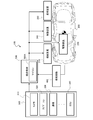
- FIG. 2 is a diagram showing the control contents of the integrated control controller 500 when the vehicle 200 travels on a rutted road surface.
- a rut is a trace of a wheel (in other words, a groove or a recess) that remains on the road surface after a car has passed, and occurs on a snowy road or an unpaved road. The case of ruts on the road will be described.
- the integrated control controller 500 detects a rut in front of the vehicle 200 based on the preview information from the stereo camera 310, the vehicle 200 travels along the rut at the traveling speed of the vehicle 200 before the vehicle 200 enters the rut. Decelerate to a predetermined appropriate vehicle speed that can ensure stability when the vehicle is used. As a result, the integrated control controller 500 causes the vehicle 200 to enter the rut at a speed equal to or lower than the appropriate vehicle speed.
- the integrated control controller 500 adjusts the vehicle 200 to an appropriate vehicle speed by performing control for reducing the driving force generated by the driving device 230 and / or controlling for increasing the braking force generated by the braking device 240. Decelerate to. That is, when the integrated control controller 500 detects a rut in front of the vehicle, the drive device 230 and the drive device 230 and the vehicle speed are lowered as compared with before detecting the rut, in other words, as compared with when traveling on a road surface without ruts. / Or outputs a deceleration control command (third control command) to the braking device 240.
- the integrated control controller 500 raises the vehicle height when the vehicle 200 travels on a rut, as compared with when the vehicle 200 travels on a road surface without ruts.
- a control command (first control command) for raising the vehicle height is output to the suspension device 220.
- the integrated control controller 500 controls the toe-in when the vehicle 200 travels in a rut. carry out.
- the integrated control controller 500 performs toe-in control when the vehicle 200 travels on the rut so that the toe angle of the front wheels is directed more inward than when the vehicle 200 does not travel on the rut, so that the vehicle 200 travels along the rut. Improves stability when doing. As described above, when the vehicle 200 travels in a rut, the integrated control controller 500 performs deceleration to an appropriate vehicle speed for rut travel, an increase in vehicle height, and three-axis control of toe-in, thereby causing the vehicle 200 to perform three-axis control. Ensure stability when driving on ruts.
- the integrated control controller 500 makes the vehicle 200 move along the center of the rut when the vehicle 200 travels in the rut, in other words, the left and right wheels are fitted in the rut.
- a control command (second control command) for the target trajectory is output to the steering device 210 so as to travel along the line.
- the center of the ruts is the center of the distance between the left and right ruts (see FIG. 2).
- the integrated control controller 500 since the integrated control controller 500 has deep ruts, it is not possible to sufficiently suppress the interference between the vehicle 200 and the snow cover even if the control for raising the vehicle height to the maximum is performed. If it is determined that the vehicle cannot be secured, a correction process is performed to offset the target track in automatic driving by a predetermined distance in the left-right direction from the center of the rut, and the steering device 210 is used to drive the vehicle 200 along the corrected target track.
- a control command for the steering angle (second control command) is output to. That is, the integrated control controller 500 acquires the target trajectory based on the specifications related to the disturbance (identification information of the rudder) and the specifications related to the road shape (in other words, the information related to the road shape) in the road surface condition. , A control command (second control command) related to steering is output to the steering device 210 so that the vehicle 200 travels along the target track.
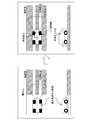
- FIG. 3 shows the control contents of the integrated control controller 500 when the vehicle 200 travels in the snowdrift.
- a snowdrift is a place where snow or fallen leaves are blown by the wind and is deposited on the road or a deposit (convex portion) on the road.
- snow is blown as an example. The case of the snowdrift will be described.
- the traveling speed of the vehicle 200 is set when the vehicle 200 travels in the snowdrift before the vehicle 200 enters the snowdrift. Decelerate to a predetermined appropriate vehicle speed that can ensure stability. As a result, the integrated control controller 500 causes the vehicle 200 to enter the snowdrift at a speed equal to or lower than the appropriate vehicle speed.
- the integrated control controller 500 adjusts the vehicle 200 to an appropriate vehicle speed by performing control for reducing the driving force generated by the driving device 230 and / or controlling for increasing the braking force generated by the braking device 240. Decelerate to. That is, when the integrated control controller 500 detects a snowdrift in front of the vehicle, the vehicle speed is lower than before the snowdrift is detected, in other words, when the vehicle travels on a road surface without a snowdrift. / Or outputs a deceleration control command (third control command) to the braking device 240.
- the integrated control controller 500 raises the vehicle height when the vehicle 200 travels in the snowdrift as compared with when traveling on a road surface without the snowdrift.
- a control command (first control command) for raising the vehicle height is output to the suspension device 220.
- the integrated control controller 500 gives a steering angle control command to the steering device 210 so that when the vehicle 200 travels in the snowdrift, the yaw moment is generated in the direction opposite to the yaw moment generated by the runway resistance due to the snowdrift.
- the second control command) is output to cancel the yaw moment generated by the track resistance of the snowdrift.
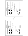
- FIG. 4 shows control of a target trajectory for running the vehicle 200 while avoiding snowdrifts.
- the integrated control controller 500 detects a snowdrift in front of the vehicle 200, if an avoidance condition such as no oncoming vehicle is satisfied, the integrated control controller 500 corrects the target trajectory so as to avoid the snowdrift, and follows the corrected target track.
- the vehicle 200 can be driven. That is, the integrated control controller 500 acquires the target trajectory based on the specifications related to the disturbance in the road surface condition (identification information of the snowdrift) and the specifications related to the road shape (in other words, the information related to the road shape).
- a control command (second control command) related to steering is output to the steering device 210 so that the vehicle 200 travels along the target track.
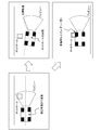
- FIG. 5 shows the control contents of the integrated control controller 500 when a pothole is detected in front of the vehicle 200.
- the pothole is a hole (or recess) having a length of about 0.1 m to 1 m formed on a paved road surface (for example, asphalt pavement).
- the integrated control controller 500 detects a pothole in front of the vehicle 200 based on the preview information from the stereo camera 310, the vehicle 200 determines the traveling speed of the vehicle 200 and the vehicle 200 determines the pothole before the vehicle 200 enters the pothole. Decelerate to a predetermined appropriate vehicle speed that can ensure stability when driving. As a result, the integrated control controller 500 causes the vehicle 200 to enter the pothole at a speed equal to or lower than the appropriate vehicle speed.
- the integrated control controller 500 adjusts the vehicle 200 to an appropriate vehicle speed by performing control for reducing the driving force generated by the driving device 230 and / or controlling for increasing the braking force generated by the braking device 240. Decelerate to. That is, when the integrated control controller 500 detects a pothole in front of the vehicle, the integrated control controller 500 is driven so that the vehicle speed is lower than before detecting the pothole, in other words, when traveling on a road surface without a pothole.
- a deceleration control command (third control command) is output to the device 230 and / or the braking device 240.
- the integrated control controller 500 outputs a control command for the vehicle height and / or damping force to the suspension device 220 in order to prevent the wheels of the vehicle 200 from falling into the pothole and applying an impact to the vehicle body.
- the integrated control controller 500 tightens the lifting control command (first control command) and / or the damper (in other words, the shock absorber) for the wheels predicted to travel on the pothole, in other words.
- a control command (first control command) for increasing the damping force which is the resistance force generated by the damper, is output to the suspension device 220.
- the integrated control controller 500 can drive the vehicle 200 on a track that avoids the pothole, the integrated control controller 500 corrects the vehicle 200 to a target track that avoids the pothole so that the vehicle 200 runs along the target track. It is possible to output a steering angle control command (second control command) to the steering device 210. That is, the integrated control controller 500 is based on the specifications related to the disturbance in the road surface condition (specifically, the identification information of the pothole) and the specifications related to the road shape (in other words, the information related to the road shape).
- the target track is acquired, and a control command (second control command) related to steering is output to the steering device 210 so that the vehicle 200 travels along the target track.
- FIG. 6 shows the control contents of the integrated control controller 500 when a bump is detected in front of the vehicle 200.
- a bump is a raised object (for example, a speed bump or a speed cushion) that is intentionally installed to encourage the driver to decelerate by indicating a place where a part of the road is raised due to a construction mark or the like. Can be excluded.
- the traveling speed of the vehicle 200 is set when the vehicle 200 travels on the bump before the vehicle 200 enters the bump. Decelerate to a predetermined appropriate vehicle speed that can ensure stability. As a result, the integrated control controller 500 causes the vehicle 200 to enter the bump at a speed equal to or lower than the appropriate vehicle speed.
- the integrated control controller 500 adjusts the vehicle 200 to an appropriate vehicle speed by performing control for reducing the driving force generated by the driving device 230 and / or controlling for increasing the braking force generated by the braking device 240. Decelerate to. That is, when the integrated control controller 500 detects a bump in front of the vehicle, the drive device 230 and the drive device 230 and the vehicle speed are lowered so that the vehicle speed is lower than before the bump is detected, in other words, when the vehicle travels on a road surface without bumps. / Or outputs a deceleration control command (third control command) to the braking device 240.
- the integrated control controller 500 outputs a control command for the vehicle height and / or damping force to the suspension device 220 in order to suppress the vertical vibration of the vehicle 200 when the wheels of the vehicle 200 ride on the bumps.
- the integrated control controller 500 softens the lifting control command (first control command) or the damper (in other words, the shock absorber) for the wheel predicted to ride on the bump, in other words, the damper A control command (first control command) for lowering the damping force, which is the generated resistance force, is output to the suspension device 220.
- the integrated control controller 500 corrects the vehicle 200 to a target track that avoids bumps, and steers the vehicle 200 so that the vehicle 200 travels along the target track. It is possible to output a steering angle control command (second control command) to the device 210. That is, the integrated control controller 500 acquires the target trajectory based on the specifications related to the disturbance in the road surface condition (bump identification information) and the specifications related to the road shape (in other words, information related to the road shape). , A control command (second control command) related to steering is output to the steering device 210 so that the vehicle 200 travels along the target track.
- FIG. 7 shows the control contents of the integrated control controller 500 when a curved road (in other words, the curvature of the road surface) is detected in front of the vehicle 200.
- the integrated control controller 500 detects a curved road in front of the vehicle 200 based on preview information and map information from the stereo camera 310, the traveling speed of the vehicle 200 is set to the vehicle 200 before the vehicle 200 enters the curved road. Decelerates to a predetermined appropriate vehicle speed that can ensure stability when driving on a curved road. As a result, the integrated control controller 500 causes the vehicle 200 to enter the curved road at a speed equal to or lower than the appropriate vehicle speed.
- the integrated control controller 500 adjusts the vehicle 200 to an appropriate vehicle speed by performing control for reducing the driving force generated by the driving device 230 and / or controlling for increasing the braking force generated by the braking device 240. Decelerate to. That is, when the integrated control controller 500 detects a curved road in front of the vehicle, the vehicle speed is lower than before detecting the curved road, in other words, the vehicle speed is lower than when traveling on a straight road. / Or outputs a deceleration control command (third control command) to the braking device 240.
- the integrated control controller 500 gives a vehicle height adjustment control command (first control command) to the suspension device 220 so that the vehicle height on the inside of the turn is lower than the height of the vehicle on the outside of the turn among the left and right vehicle heights of the vehicle 200.
- first control command a vehicle height adjustment control command
- the integrated control controller 500 reduces the vehicle height inside the turn and raises the vehicle height outside the turn from the state where the left and right vehicle heights are controlled to be the same, thereby performing vehicle height control inside the turn.
- the vehicle height of is lower than the vehicle height on the outside of the turn.
- the integrated control controller 500 includes a state estimation unit 510 and an integrated control execution unit 520, and further, the integrated control execution unit 520 includes a vehicle behavior control unit 530, a track tracking control unit 540, and a distribution control unit 550.
- the state estimation unit 510 includes a road surface determination unit 511, a vehicle state quantity estimation unit 512, and a track generation unit 513.
- the road surface determination unit 511 acquires road surface displacement, road shape, peripheral information, etc. from the outside world recognition unit 300, and specifies information such as ruts, snowdrifts, potholes, bumps, etc., that is, specifications related to the road condition including disturbance information. Is calculated and output.
- the vehicle state quantity estimation unit 512 acquires road condition information and the like output by the road surface determination unit 511, and estimates the vehicle condition quantity including the estimated vehicle speed, side slip angle, vehicle height, self-position, and the like.
- the estimated vehicle speed is the vehicle speed data obtained based on the wheel speed information.
- the track generation unit 513 acquires road shape and surrounding information from the outside world recognition unit 300, and also acquires road condition information including disturbance information (for example, identification information such as ruts) from the road surface determination unit 511.
- the track generation unit 513 generates a target track that avoids the disturbance according to conditions such as a state of disturbance such as a snowdrift and the presence or absence of an oncoming vehicle. Further, the track generation unit 513 generates a target track so that the position of the center of gravity of the vehicle 200 moves along the center of the rut when the vehicle 200 travels on the rut, and further, travels along the rut. If it is determined that the vehicle height is not sufficient to enable it, a target track offset from the center of the rut by a predetermined distance in the left-right direction is generated.
- the road surface determination unit 511 determines the road surface condition in front of the vehicle 200 based on the specifications related to the road surface displacement and the specifications related to the road shape, and the track generation unit 513 determines various disturbances related to the road surface condition. Obtain the target trajectory based on the original and the specifications related to the road shape.
- the vehicle behavior control unit 530 of the integrated control execution unit 520 includes a vehicle speed control unit 531 and an attitude control unit 532.
- the vehicle speed control unit 531 acquires information on vehicle speed commands and acceleration commands in automatic driving (advanced driving support) from the outside world recognition unit 300, in other words, information on the control amount related to the speed of the vehicle 200, and estimates the vehicle state amount.
- Information on the estimated vehicle speed is acquired from the unit 512, and further, information on the target vehicle speed according to the disturbance of the road surface is acquired from the attitude control unit 532.
- the vehicle speed control unit 531 determines whether or not there is a deceleration request before entering a disturbance such as a rut from the information of the target vehicle speed according to the disturbance of the road surface and the information of the vehicle speed command in the automatic driving, and determines the final target. Determine the vehicle speed. Further, the vehicle speed control unit 531 obtains the target front-rear acceleration based on the comparison between the final target vehicle speed and the estimated vehicle speed, and outputs the information of the obtained target front-rear acceleration.
- a disturbance such as a rut
- the attitude control unit 532 acquires the information of the target track from the track generation unit 513, and acquires the vehicle state amount information including the approach state of the road surface to the disturbance from the vehicle state amount estimation unit 512, and obtains the information of the vehicle state amount in these. Based on this, the target vehicle height, target roll moment, target lateral acceleration, etc. are calculated and output. That is, when the vehicle 200 travels on a disturbed portion of the road surface such as a rut or a snowdrift, the attitude control unit 532 changes the target vehicle height so as to raise the vehicle height, and the yaw generated by the runway resistance due to the snowdrift.
- the target lateral acceleration is set so as to generate a yaw moment in the direction opposite to the moment.
- the attitude control unit 532 outputs a toe-in request when the vehicle 200 travels on a rut, and outputs a damping force and / or a vehicle height adjustment request when the vehicle 200 travels on a bump or a pothole. Further, when the vehicle 200 travels on a curved road, it outputs a request for left and right vehicle height adjustment.
- the vehicle behavior control unit 530 including the vehicle speed control unit 531 and the attitude control unit 532 controls the vehicle state quantity including the estimated vehicle speed of the vehicle 200, the target track, and the speed of the vehicle 200 (specifically, in detail, The vehicle behavior control amount is acquired based on the vehicle speed command and acceleration command).
- the track tracking control unit 540 acquires information on its own position (own vehicle position) from the vehicle state quantity estimation unit 512 and information on the target track from the track generation unit 513, and traces the vehicle 200 to the target track. Information on the target lateral acceleration (trajectory tracking control amount) of is obtained and output. That is, the track tracking control unit 540 acquires the track tracking control amount based on the self-position of the vehicle 200 and the target track among the estimated state quantities of the vehicle 200.
- the distribution control unit 550 includes a front / rear / pitch control unit 551, an up / down / roll control unit 552, and a left / right / yaw control unit 553, and constitutes a drive device 230, a braking device 240, a suspension device 220, and steering.
- a control command is output to each of the devices 210.
- the front-rear / pitch control unit 551 acquires information on the target front-rear acceleration from the vehicle speed control unit 531, and based on the comparison between the target front-rear acceleration and the actual front-rear acceleration, the control command (third control) for realizing the target front-rear acceleration.
- a drive torque control command is output to the drive device 230, and a braking torque control command is output to the braking device 240.
- the vertical / roll control unit 552 acquires information such as a target vehicle height, a target roll moment, and a target damping force from the attitude control unit 532, and based on these, a control command (first control) for adjusting the vehicle height and damping force. Command) is output to the suspension device 220.
- the left / right / yaw control unit 553 acquires information on the target lateral acceleration from the attitude control unit 532 and the trajectory tracking control unit 540, and issues a control command (second control command) for adjusting the rudder angle based on the information of the steering device 210. Output to.
- the distribution control unit 550 controls the suspension device 220 based on the vehicle behavior control amount from the vehicle behavior control unit 530 and the track follow control amount from the track follow control unit 540. It outputs a command, a second control command for controlling the steering device 210, and a third control command for controlling the control drive device (drive device 230 and braking device 240).
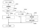
- FIG. 9 is a flowchart showing the procedure of control processing of each of the steering device 210, the suspension device 220, the driving device 230, and the braking device 240 by the integrated control controller 500.
- the integrated control controller 500 determines whether or not the steering device 210, the driving device 230, the braking device 240, and the external world recognition unit 300 are normal, and if any of them is abnormal, the automatic operation and the advanced operation are performed. Since support cannot be provided, the arithmetic processing is terminated without performing various controls.
- step S1100 determines whether or not a rut has been detected in front of the vehicle 200. To do.
- step S1200 determines whether or not a snowdrift is detected in front of the vehicle 200.
- the integrated control controller 500 causes the vehicle 200 to travel along the target track in step S1300. Perform orbit tracking control. Further, the integrated control controller 500 proceeds to step S1400 to perform control (control 1) when the vehicle 200 travels on the rutted road surface.
- step S1401 the integrated control controller 500 implements control drive control for decelerating the vehicle 200 to a predetermined appropriate vehicle speed suitable for rut running before the vehicle 200 enters the rut. That is, in step S1401, the integrated control controller 500 outputs a control command (third control command) for decelerating the vehicle 200 to an appropriate vehicle speed for rut running to the drive device 230 and / or the braking device 240 (FIG. FIG. 2).
- step S1402 determines in step S1402 whether or not the suspension device 220 is normal. Then, if the suspension device 220 is normal, the integrated control controller 500 proceeds to step S1403 and adjusts the vehicle height so that the lower surface of the vehicle 200 does not rub against the snow when traveling with the wheels fitted in the ruts. Control to implement.
- the integrated control controller 500 when the suspension device 220 is normal, the integrated control controller 500 outputs a control command (first control command) for raising the vehicle height of the vehicle 200 to the suspension device 220 in step S1403 (see FIG. 2). ..
- the integrated control controller 500 cancels the vehicle height adjustment by bypassing step S1403 and proceeding to step S1404.
- step S1404 the integrated control controller 500 determines whether or not the vehicle height is secured so that the lower surface of the vehicle 200 is not rubbed by snow. Then, if the vehicle height required for rut running is secured, the integrated control controller 500 bypasses step S1405 and step S1406 and proceeds to step S1407, so that the wheels of the vehicle 200 are fitted into the ruts. Try to run.
- step S1405. Set to offset the target trajectory from the center of the rut. That is, if the vehicle travels in a state where the wheels of the vehicle 200 are fitted in the ruts, the lower surface of the vehicle 200 may be rubbed by snow due to insufficient vehicle height. Therefore, the integrated control controller 500 does not fit the wheels of the vehicle 200 in the ruts. Correct the target trajectory so that it runs on the wheel.
- the integrated control controller 500 outputs a steering angle command (second control command) such that the vehicle 200 traces the corrected target trajectory to the steering device 210. If the target trajectory is corrected in step S1405, the vehicle 200 will travel on a road surface having a large track resistance that the preceding vehicle does not pass through. Therefore, the integrated control controller 500 increases the drive torque in the next step S1406. ..
- the integrated control controller 500 can secure the vehicle height required for rut running, and when the vehicle 200 is run along the rut, the process proceeds to step S1407, and the steering device 210 can adjust the toe angle independently on the left and right. If it is determined whether or not the system is a by-wire system and the toe angle can be adjusted independently on the left and right, the process proceeds to step S1408.
- the integrated control controller 500 is a toe-in control command (first) in which the toe angle of the front wheels is directed more inward than when the wheels are not running in order to improve the stability when the wheels are fitted in the ruts. 2 Control command) is output to the steering device 210 (see FIG. 2).
- step S1200 of the flowchart of FIG. 9 that is, when it detects a rut and a snowdrift in front of the vehicle 200
- the integrated control controller 500 proceeds to step S1500 and moves the vehicle 200 along the target track. Carry out track-following control to drive. Further, the integrated control controller 500 performs control (control 2) for traveling on a snowy road in which ruts and snowdrifts are present in the next step S1600.
- step S1601-step S1608 is the same as that of step S1401-step S1408 described above, and thus detailed description thereof will be omitted.
- the integrated control controller 500 performs deceleration control, vehicle height control, target trajectory correction control, and toe angle control in step S1601-step S1608, and then proceeds to step S1609. Then, the integrated control controller 500 generates a yaw moment in the direction opposite to the yaw moment generated by the runway resistance due to the snowdrift when the vehicle 200 travels in the snowdrift in step S1609 and in step S1609.
- a control command for the steering angle (second control command) is output to offset the yaw moment generated by the runway resistance due to snowdrift (see FIG. 3).
- step S1700 determines whether or not a snowdrift has been detected. Then, when the integrated control controller 500 detects a snowdrift in front of the vehicle, the integrated control controller 500 proceeds to step S1800 to perform track tracking control for traveling the vehicle 200 along the target track, and further, in the next step S1900, the vehicle 200 Controls (control 3) when the vehicle travels in the snowdrift.
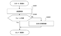
- the flowchart of FIG. 12 shows the details of the processing content (control 3) of step S1900.
- step S1901 the integrated control controller 500 implements control drive control for decelerating to a predetermined appropriate vehicle speed suitable for snowdrift running before the vehicle 200 enters the snowdrift. That is, in step S1901, the integrated control controller 500 outputs a control command (third control command) for decelerating the vehicle 200 to an appropriate vehicle speed for snowdrift running to the drive device 230 and / or the braking device 240.
- a control command third control command
- step S1902 the integrated control controller 500 proceeds to step S1902 to determine whether or not it is possible to drive the vehicle 200 while avoiding (bypassing) the snowdrift, such as the presence or absence of an oncoming vehicle, the size and position of the snowdrift, and the like. Judgment is based on driving conditions. Then, when it is possible to avoid the snowdrift, the integrated control controller 500 proceeds to step S1903, and corrects the target trajectory (in other words, the target traveling trajectory) of the vehicle 200 to a track that avoids the snowdrift (FIG. 4), a steering angle command (second control command) for the vehicle 200 to trace the corrected target trajectory is output to the steering device 210.
- the target trajectory in other words, the target traveling trajectory
- a steering angle command second control command
- the integrated control controller 500 proceeds to step S1904 and determines whether or not the suspension device 220 is normal. Then, when the suspension device 220 is normal, the integrated control controller 500 proceeds to step S1905 and performs vehicle height control to raise the vehicle height of the vehicle 200 more than before entering the snowdrift to improve the running stability (). (See FIG. 3).
- the integrated control controller 500 outputs a vehicle height control command (first control command) for raising the vehicle height of the vehicle 200 to the suspension device 220 when the vehicle 200 travels in the snowdrift.
- first control command a vehicle height control command for raising the vehicle height of the vehicle 200 to the suspension device 220 when the vehicle 200 travels in the snowdrift.
- the integrated control controller 500 bypasses step S1905 and proceeds to step S1906 to cancel the vehicle height adjustment.
- step S1906 the integrated control controller 500 controls the steering angle of the steering device 210 so that when the vehicle 200 travels in the snowdrift, the yaw moment is generated in the direction opposite to the yaw moment generated by the runway resistance due to the snowdrift.
- a command (second control command) is output to cancel the yaw moment generated by the runway resistance due to the snowdrift (see FIG. 3).
- step S1700 of the flowchart of FIG. 9 the integrated control controller 500 proceeds to step S2000 and determines whether or not a pothole has been detected. Then, when the integrated control controller 500 detects the pothole, the integrated control controller 500 proceeds to step S2100 to perform track tracking control for traveling the vehicle 200 along the target track.
- control controller 500 executes control (control 4) when the vehicle 200 travels in the pothole in the next step S2200.
- control control 4
- the flowchart of FIG. 13 shows the details of the processing content (control 4) of step S2200.
- step S2201 the integrated control controller 500 implements control drive control for decelerating the vehicle 200 to a predetermined appropriate vehicle speed suitable for pothole driving before the vehicle 200 enters the pothole. That is, in step S2201, the integrated control controller 500 outputs a control command (third control command) for decelerating the vehicle 200 to an appropriate vehicle speed for pothole traveling to the drive device 230 and / or the braking device 240.
- a control command third control command
- step S2202 determines whether or not it is possible to drive the vehicle 200 while avoiding (bypassing) the pothole, as to whether or not there is an oncoming vehicle, the size and position of the pothole. Judgment is made based on driving conditions such as. Then, when it is possible to avoid the pothole, the integrated control controller 500 proceeds to step S2203, corrects the target track of the vehicle 200 to a track that avoids the pothole (see FIG. 5), and after the correction. A steering angle command (second control command) for the vehicle 200 to trace the target trajectory is output to the steering device 210.
- step S2203 corrects the target track of the vehicle 200 to a track that avoids the pothole (see FIG. 5), and after the correction.
- a steering angle command (second control command) for the vehicle 200 to trace the target trajectory is output to the steering device 210.
- the integrated control controller 500 proceeds to step S2204 and determines whether or not the suspension device 220 is normal. Then, when the suspension device 220 is normal, the integrated control controller 500 proceeds to step S2205 and performs vehicle height control for lifting the wheels entering the pothole (see FIG. 5).
- the integrated control controller 500 implements damping force control for hardening the dampers of the wheels entering the pothole, in other words, increasing the damping force (see FIG. 5).
- the integrated control controller 500 may perform either the vehicle height control in step S2205 or the damping force control in step S2206 when the suspension device 220 is a fully active suspension whose vehicle height can be adjusted. it can.
- the integrated control controller 500 can cancel the process of step S2205 and carry out step S2206. In this way, the integrated control controller 500 outputs a control command (first control command) for preventing the wheels from falling into the pothole when the vehicle 200 travels in the pothole, thereby outputting the control command (first control command) to the suspension device 220. , Improves stability when the vehicle 200 travels in a pothole.
- step S2300 determines whether or not a bump has been detected. Then, when the integrated control controller 500 detects a bump, the integrated control controller 500 proceeds to step S2400 to perform track tracking control for traveling the vehicle 200 along the target track.
- control controller 500 executes control (control 5) when the vehicle 200 travels on the bump in the next step S2500.
- control control 5
- the flowchart of FIG. 14 shows the details of the processing content (control 5) of step S2500.
- step S2501 the integrated control controller 500 performs control drive control for decelerating the vehicle 200 to a predetermined appropriate vehicle speed suitable for bump running before the vehicle 200 enters the bump. That is, in step S2501, the integrated control controller 500 outputs a control command (third control command) for decelerating the vehicle 200 to an appropriate vehicle speed for bump traveling to the drive device 230 and / or the braking device 240.
- a control command third control command
- step S2502 the integrated control controller 500 proceeds to step S2502 to determine whether or not the vehicle 200 can be driven by avoiding (bypassing) the bumps, such as the presence or absence of an oncoming vehicle, the size and position of the bumps, and the like. Judgment is based on driving conditions. Then, when it is possible to avoid the bumps, the integrated control controller 500 proceeds to step S2503, corrects the target trajectory of the vehicle 200 to a track that avoids the bumps (see FIG. 6), and corrects the target trajectory. Is output to the steering device 210 so that the vehicle 200 traces the steering angle command (second control command).
- the integrated control controller 500 proceeds to step S2504 and determines whether or not the suspension device 220 is normal. Then, when the suspension device 220 is normal, the integrated control controller 500 proceeds to step S2505 and performs vehicle height control for lifting the wheels entering the bump (see FIG. 6).
- the integrated control controller 500 performs damping force control for softening the damper of the wheel entering the bump, in other words, lowering the damping force (see FIG. 6).
- the integrated control controller 500 may perform either the vehicle height control in step S2505 or the damping force control in step S2506 when the suspension device 220 is a fully active suspension whose vehicle height can be adjusted. it can.
- the integrated control controller 500 can cancel the process of step S2505 and carry out step S2506. In this way, the integrated control controller 500 outputs a control command (first control command) for suppressing the impact from being transmitted to the vehicle body when the vehicle 200 travels on the bump, thereby outputting the vehicle to the suspension device 220. Improves stability when the 200 runs on the bump.
- step S2600 determines whether or not a curved road has been detected. Then, when the integrated control controller 500 detects a curved road, the integrated control controller 500 proceeds to step S2700 to perform track-following control for driving the vehicle 200 along the target track.
- control controller 500 executes control (control 6) when the vehicle 200 travels on a curved road in the next step S2800.
- control 6) when the vehicle 200 travels on a curved road in the next step S2800.
- the flowchart of FIG. 15 shows the details of the processing content (control 6) of step S2800.
- step S2801 the integrated control controller 500 performs control drive control for decelerating to a predetermined appropriate vehicle speed suitable for curve traveling (turning traveling) before the vehicle 200 enters the curved road (see FIG. 7). That is, in step S2801, the integrated control controller 500 outputs a control command (third control command) for decelerating the vehicle 200 to an appropriate vehicle speed for traveling on a curved road to the drive device 230 and / or the braking device 240.
- a control command third control command
- step S2802 the integrated control controller 500 proceeds to step S2802 to determine whether or not the suspension device 220 is normal. Then, when the suspension device 220 is normal, the integrated control controller 500 proceeds to step S2803 to suppress the lateral acceleration (lateral acceleration) felt by the driver (occupant) when the vehicle 200 travels on a curved road. Carry out vehicle height control.
- step S2803 the integrated control controller 500 outputs a vehicle height adjustment control command (first control command) to the suspension device 220 so that the vehicle height inside the turn is lower than the vehicle height outside the turn on the curved road.
- first control command a vehicle height adjustment control command
- the integrated control controller 500 can predict the lateral acceleration generated during the curve traveling and adjust the difference in vehicle height between the inner and outer wheels of the turn based on the prediction result.
- step S2600 of the flowchart of FIG. 9 that is, all of ruts, snowdrifts, potholes, bumps, and curved roads. If a flat and substantially straight road extends in front of the vehicle 200 without detecting the above, the process proceeds to step S2900, and track tracking control for driving the vehicle 200 along the target track is performed.
- the integrated control controller 500 has the snowdrift or bump. Even if it is possible to avoid disturbances such as potholes, the vehicle 200 can be driven without changing the target trajectory. Further, even when the vehicle height of the vehicle 200 can be adjusted to a sufficient height on the rut road surface, the target trajectory of the vehicle 200 is offset to the left and right by a predetermined distance from the center of the rut (the center of the distance between the left and right ruts). Can be made to.
- the vehicle 200 covers a portion where the height of the snowdrift or bump is lower than the predetermined value, or a portion where the depth of the pot hole is shallower than the predetermined value or the size is smaller than the predetermined value.
- the target trajectory of the vehicle 200 can be changed so as to travel.
- the integrated control controller 500 can change the appropriate vehicle speed targeted in the deceleration control before entering the disturbance according to the height of snowdrifts and bumps, or the depth of ruts and potholes.
- the integrated control controller 500 sets the adjustment allowance for the lifting amount and the damping force in the wheel lifting control and the damping force adjustment control when the vehicle 200 travels on the pothole or the bump, by adjusting the depth and size of the pothole. It can be changed according to the height of the bump. Further, the integrated control controller 500 gives a steering angle control command (No. 1) to the steering device 210 so that the yaw moment is generated in the direction opposite to the yaw moment generated when one of the left and right wheels travels on a bump or a pot hole. 2 Control command) can be output.
- the integrated control controller 500 when the integrated control controller 500 detects a bump (for example, a speed bump or a speed cushion) intentionally installed in front of the vehicle 200 to encourage the driver to decelerate, the integrated control controller 500 lifts a wheel that overcomes the bump.
- a control command (first control command) can be output to the suspension device 220 so as to weaken the damping force of the damper of the wheel overcoming the bump.
- the partial unevenness of the road surface on which vehicle control is performed is ruts, snowdrifts, potholes, and bumps, but the disturbance is not limited to these.
- the integrated control controller 500 detects a falling object on a road having a height of a predetermined value or less, a floor plate placed on the road for road construction, etc. as a convex portion as a disturbance, and before entering the disturbance.
- the suspension device 220 is controlled to lift the wheels and / or to weaken the damping force, or is changed to a target trajectory to avoid the convex portion. Steering control can be performed.
Abstract
The vehicle control device according to the present invention: acquires various elements pertaining to a road condition in front of a vehicle on the basis of outside information; acquires a vehicle behavior control amount for controlling the behavior of the vehicle on the basis of an estimated state amount of the vehicle obtained on the basis of the various elements, and a control amount based on the outside information and related to the speed of the vehicle; acquires, on the basis of a target path for the vehicle to travel, which is determined on the basis of the various elements, and the estimated state amount, a path following control amount for causing the vehicle to follow the target path; and outputs a control command for controlling each of a suspension device, a steering device, and a braking and driving device, on the basis of the vehicle behavior control amount and the path following control amount. This improves travel stability of the vehicle on a road surface where disturbances such as ruts are present.
Description
本発明は、車両制御装置、車両制御方法、及び車両制御システムに関する。
The present invention relates to a vehicle control device, a vehicle control method, and a vehicle control system.
特許文献1の走行制御装置は、地図情報に基づいて自車両が走行する路面上の目標コースを第1のコースとして設定し、轍情報に基づいて自車両が走行する路面上の目標コースを第2、第3のコースとして設定し、第1のコースと第2、第3のコースとを比較し、走行路情報と轍情報とに基づき自車両が走行する路面上の目標コースを設定する。
The travel control device of Patent Document 1 sets the target course on the road surface on which the own vehicle travels as the first course based on the map information, and sets the target course on the road surface on which the own vehicle travels based on the rut information. The second and third courses are set, the first course is compared with the second and third courses, and the target course on the road surface on which the own vehicle travels is set based on the driving road information and the rut information.
ところで、路面に轍などの外乱が存在する場合に、目標コース(目標軌道)を選択し、選択した目標コースをトレースさせるように操舵角制御を実施するだけでは、外乱の影響に十分に対処できず、車両の走行安定性を確保することが難しいという問題があった。
By the way, when there is a disturbance such as a rut on the road surface, the influence of the disturbance can be sufficiently dealt with simply by selecting the target course (target trajectory) and controlling the steering angle so as to trace the selected target course. However, there is a problem that it is difficult to secure the running stability of the vehicle.
本発明は、従来の実情に鑑みてなされたものであり、その目的は、轍のような外乱が存在する路面上での車両の走行安定性を向上させることができる、車両制御装置、車両制御方法、及び車両制御システムを提供することにある。
The present invention has been made in view of the conventional circumstances, and an object of the present invention is a vehicle control device and a vehicle control capable of improving the running stability of a vehicle on a road surface in which a disturbance such as a rut exists. The method and the vehicle control system are to be provided.
本発明によれば、その1つの態様において、外界認識部から取得した外界情報に基づいて、車両が走行する前方の道路状態に関する諸元を取得し、前記道路状態に関する諸元に基づき求められた前記車両の推定状態量と、前記外界情報に基づく前記車両の速度に関する制御量と、に基づいて前記車両の挙動を制御するための車両挙動制御量を取得し、前記道路状態に関する諸元に基づき求められた前記車両が走行する目標軌道と、前記推定状態量と、に基づいて前記目標軌道に前記車両を追従させるための軌道追従制御量を取得し、前記車両挙動制御量と、前記軌道追従制御量と、に基づいて、懸架装置を制御するための第1制御指令と、操舵装置を制御するための第2制御指令と、制駆動装置を制御するための第3制御指令と、を出力する。
According to the present invention, in one aspect thereof, the specifications relating to the road condition in front of the vehicle are acquired based on the external world information acquired from the external world recognition unit, and the specifications are obtained based on the specifications relating to the road condition. The vehicle behavior control amount for controlling the behavior of the vehicle is acquired based on the estimated state amount of the vehicle and the control amount related to the speed of the vehicle based on the outside world information, and based on the specifications related to the road condition. Based on the obtained target track on which the vehicle travels and the estimated state quantity, a track tracking control amount for making the vehicle follow the target track is acquired, and the vehicle behavior control amount and the track tracking are obtained. Based on the control amount, a first control command for controlling the suspension device, a second control command for controlling the steering device, and a third control command for controlling the control drive device are output. To do.
本発明によれば、轍のような外乱が存在する路面上での車両の走行安定性を向上させることができる。
According to the present invention, it is possible to improve the running stability of a vehicle on a road surface in which a disturbance such as a rut exists.
以下、本発明に係る車両制御装置、車両制御方法、及び車両制御システムの実施形態を、図面に基づいて説明する。
図1は、車両制御システム100の一態様を示す概略ブロック図である。 Hereinafter, a vehicle control device, a vehicle control method, and an embodiment of a vehicle control system according to the present invention will be described with reference to the drawings.
FIG. 1 is a schematic block diagram showing one aspect of thevehicle control system 100.
図1は、車両制御システム100の一態様を示す概略ブロック図である。 Hereinafter, a vehicle control device, a vehicle control method, and an embodiment of a vehicle control system according to the present invention will be described with reference to the drawings.
FIG. 1 is a schematic block diagram showing one aspect of the
図1の車両200は、自動運転可能な車両であって、操舵装置210、懸架装置220、駆動装置230、制動装置240を有する。
操舵装置210は、電動パワーステアリング(換言すれば、機械式ステアリング)やステアバイワイヤシステムなどの転舵アクチュエータによって転舵角の電子制御が可能な装置である。 Thevehicle 200 of FIG. 1 is a vehicle that can be automatically driven, and has a steering device 210, a suspension device 220, a drive device 230, and a braking device 240.
Thesteering device 210 is a device capable of electronically controlling the steering angle by a steering actuator such as an electric power steering (in other words, mechanical steering) or a steer-by-wire system.
操舵装置210は、電動パワーステアリング(換言すれば、機械式ステアリング)やステアバイワイヤシステムなどの転舵アクチュエータによって転舵角の電子制御が可能な装置である。 The
The
懸架装置220は、フルアクティブサスペンションや電子制御エアサスペンションなどの油圧や空気圧といったエネルギー源によって車高及び減衰力の電子制御が可能な装置である。
駆動装置230は、モータやエンジンなどの駆動力の電子制御が可能な装置である。 Thesuspension device 220 is a device capable of electronically controlling the vehicle height and damping force by an energy source such as oil pressure or air pressure such as a fully active suspension or an electronically controlled air suspension.
Thedrive device 230 is a device capable of electronically controlling the driving force of a motor, an engine, or the like.
駆動装置230は、モータやエンジンなどの駆動力の電子制御が可能な装置である。 The
The
また、制動装置240は、摩擦ブレーキや回生ブレーキなどの制動力の電子制御が可能な装置である。
なお、駆動装置230及び制動装置240は、車両200の制駆動力を電子制御可能な制駆動装置を構成する。 Further, thebraking device 240 is a device capable of electronically controlling the braking force such as a friction brake and a regenerative brake.
Thedrive device 230 and the braking device 240 constitute a control drive device capable of electronically controlling the control drive force of the vehicle 200.
なお、駆動装置230及び制動装置240は、車両200の制駆動力を電子制御可能な制駆動装置を構成する。 Further, the
The
また、車両制御システム100は、上記の操舵装置210、懸架装置220、駆動装置230、制動装置240の他、外界認識部300、車両挙動検出部400、統合制御コントローラ500(車両制御装置)を有する。
外界認識部300は、車両200の周囲を撮影するステレオカメラ310、GPS(Global Positioning System)と地図情報とを併用するナビゲーションシステム320、車両間通信などによって外部から自車位置や外界情報などを取得する通信システム330、更に、自動運転若しくは先進運転支援システムを制御する電子制御ユニット340(AD-ECU、ADAS-ECU)などを有する。 In addition to thesteering device 210, suspension device 220, drive device 230, and braking device 240, the vehicle control system 100 includes an outside world recognition unit 300, a vehicle behavior detection unit 400, and an integrated control controller 500 (vehicle control device). ..
The outsideworld recognition unit 300 acquires the position of the own vehicle and the outside world information from the outside by a stereo camera 310 that captures the surroundings of the vehicle 200, a navigation system 320 that uses GPS (Global Positioning System) and map information together, and inter-vehicle communication. It also has an electronic control unit 330 (AD-ECU, ADAS-ECU) that controls an automatic operation or an advanced driver assistance system.
外界認識部300は、車両200の周囲を撮影するステレオカメラ310、GPS(Global Positioning System)と地図情報とを併用するナビゲーションシステム320、車両間通信などによって外部から自車位置や外界情報などを取得する通信システム330、更に、自動運転若しくは先進運転支援システムを制御する電子制御ユニット340(AD-ECU、ADAS-ECU)などを有する。 In addition to the
The outside
なお、外界認識部300は、LIDAR(Light Detection and Ranging、Laser Imaging Detection and Ranging)などを含むことができる。
また、電子制御ユニット340は、ステレオカメラ310が撮影した画像の解析などを通じて外界情報(周辺情報)を取得する機能を有する。 The outsideworld recognition unit 300 can include LIDAR (Light Detection and Ranging, Laser Imaging Detection and Ranging) and the like.
Further, theelectronic control unit 340 has a function of acquiring external world information (peripheral information) through analysis of an image taken by the stereo camera 310 or the like.
また、電子制御ユニット340は、ステレオカメラ310が撮影した画像の解析などを通じて外界情報(周辺情報)を取得する機能を有する。 The outside
Further, the
統合制御コントローラ500は、上記の操舵装置210、懸架装置220、駆動装置230、制動装置240を制御するための制御指令を求めるコントロール部としてのマイクロコンピュータ500Aを備える電子制御装置である。
統合制御コントローラ500は、外界認識部300から車速指令/加速指令、路面変位、道路形状、周辺環境などの情報を取得し、また、車両挙動検出部400から車両挙動(例えば、ヨーレート、横G、前後G、車輪速など)の情報を取得し、取得した情報を演算処理することで操舵装置210、懸架装置220、駆動装置230、制動装置240それぞれを制御するための制御指令を求めて出力する。 The integratedcontrol controller 500 is an electronic control device including a microcomputer 500A as a control unit that requests a control command for controlling the steering device 210, the suspension device 220, the driving device 230, and the braking device 240.
The integratedcontrol controller 500 acquires information such as vehicle speed command / acceleration command, road surface displacement, road shape, and surrounding environment from the outside world recognition unit 300, and vehicle behavior (for example, yaw rate, lateral G, etc.) from the vehicle behavior detection unit 400. Information on front / rear G, wheel speed, etc.) is acquired, and the acquired information is calculated and processed to obtain and output control commands for controlling each of the steering device 210, suspension device 220, drive device 230, and braking device 240. ..
統合制御コントローラ500は、外界認識部300から車速指令/加速指令、路面変位、道路形状、周辺環境などの情報を取得し、また、車両挙動検出部400から車両挙動(例えば、ヨーレート、横G、前後G、車輪速など)の情報を取得し、取得した情報を演算処理することで操舵装置210、懸架装置220、駆動装置230、制動装置240それぞれを制御するための制御指令を求めて出力する。 The integrated
The integrated
ここで、統合制御コントローラ500は、道路の曲率、轍、吹き溜まり、バンプ、ポットホールのような車両200の挙動を乱す要因となり得る車両前方の道路状態を、ステレオカメラ310からプレビュー情報として検知する。
そして、統合制御コントローラ500は、車両前方の路面に轍などの外乱が存在することを検知すると、操舵装置210、懸架装置220、駆動装置230、及び制動装置240によって、車両200の前後、左右、上下の3軸を制御することで、軌道追従制御に加えて、轍などの外乱が存在する路面において車両200の走行安定性を確保するための統合制御を実施する。 Here, the integratedcontrol controller 500 detects the road condition in front of the vehicle, such as the curvature of the road, ruts, snowdrifts, bumps, and potholes, which may disturb the behavior of the vehicle 200, as preview information from the stereo camera 310.
When the integratedcontrol controller 500 detects that a disturbance such as a rut exists on the road surface in front of the vehicle, the steering device 210, the suspension device 220, the drive device 230, and the braking device 240 use the steering device 210, the suspension device 220, the driving device 240, and the front / rear, left / right, left and right of the vehicle 200. By controlling the upper and lower three axes, in addition to the track tracking control, integrated control for ensuring the running stability of the vehicle 200 on a road surface where disturbances such as ruts exist is performed.
そして、統合制御コントローラ500は、車両前方の路面に轍などの外乱が存在することを検知すると、操舵装置210、懸架装置220、駆動装置230、及び制動装置240によって、車両200の前後、左右、上下の3軸を制御することで、軌道追従制御に加えて、轍などの外乱が存在する路面において車両200の走行安定性を確保するための統合制御を実施する。 Here, the integrated
When the integrated
ここで、統合制御コントローラ500は、前後軸の制御を、駆動装置230及び制動装置240による制駆動力制御、つまり、エンジントルク、モータトルク/回生ブレーキ、摩擦ブレーキの制御によって実施し、左右軸の制御を、操舵装置210による転舵角の制御によって実施し、上下軸の制御を、懸架装置220による車高、減衰力の制御によって実施する。
なお、轍、吹き溜まり、バンプ、ポットホールは、道路状態に関する諸元のうち、路面変位の変化に関する諸元、つまり、道路状態のうちの路面の凹凸に関する認識結果(換言すれば、路面の凹凸に関する識別情報)である。 Here, the integratedcontrol controller 500 controls the front and rear axes by controlling the driving force by the driving device 230 and the braking device 240, that is, by controlling the engine torque, the motor torque / regenerative brake, and the friction brake, and the left and right axes are controlled. The control is performed by controlling the steering angle by the steering device 210, and the control of the vertical axis is performed by controlling the vehicle height and damping force by the suspension device 220.
In addition, ruts, snowdrifts, bumps, and potholes are the specifications related to changes in road surface displacement among the specifications related to road conditions, that is, the recognition results regarding the unevenness of the road surface in the road conditions (in other words, the unevenness of the road surface). Identification information).
なお、轍、吹き溜まり、バンプ、ポットホールは、道路状態に関する諸元のうち、路面変位の変化に関する諸元、つまり、道路状態のうちの路面の凹凸に関する認識結果(換言すれば、路面の凹凸に関する識別情報)である。 Here, the integrated
In addition, ruts, snowdrifts, bumps, and potholes are the specifications related to changes in road surface displacement among the specifications related to road conditions, that is, the recognition results regarding the unevenness of the road surface in the road conditions (in other words, the unevenness of the road surface). Identification information).
統合制御コントローラ500は、ステレオカメラ310が撮影した画像の解析結果に基づき、道路状態に関する諸元(詳細には、路面の曲率や路面変位の変化に関する情報)を取得する。
以下では、車両前方の路面に轍などの外乱が存在する場合に、統合制御コントローラ500が車両200の走行安定性を確保するために実施する3軸制御を、道路状態毎(換言すれば、外乱の種別毎)に概説する。 The integratedcontrol controller 500 acquires specifications related to the road condition (specifically, information on changes in the curvature of the road surface and the displacement of the road surface) based on the analysis result of the image taken by the stereo camera 310.
In the following, when there is a disturbance such as a rut on the road surface in front of the vehicle, the integratedcontrol controller 500 performs 3-axis control for ensuring the running stability of the vehicle 200 for each road condition (in other words, the disturbance). For each type of).
以下では、車両前方の路面に轍などの外乱が存在する場合に、統合制御コントローラ500が車両200の走行安定性を確保するために実施する3軸制御を、道路状態毎(換言すれば、外乱の種別毎)に概説する。 The integrated
In the following, when there is a disturbance such as a rut on the road surface in front of the vehicle, the integrated
図2は、車両200が轍路面を走行する際の統合制御コントローラ500の制御内容を示す図である。
なお、轍とは、自動車が通った後に路面に残る車輪の跡(換言すれば、溝や凹部)であり、積雪路或いは未舗装路などで生じるが、以下の実施形態では、一例として、積雪路における轍の場合について説明する。 FIG. 2 is a diagram showing the control contents of the integratedcontrol controller 500 when the vehicle 200 travels on a rutted road surface.
A rut is a trace of a wheel (in other words, a groove or a recess) that remains on the road surface after a car has passed, and occurs on a snowy road or an unpaved road. The case of ruts on the road will be described.
なお、轍とは、自動車が通った後に路面に残る車輪の跡(換言すれば、溝や凹部)であり、積雪路或いは未舗装路などで生じるが、以下の実施形態では、一例として、積雪路における轍の場合について説明する。 FIG. 2 is a diagram showing the control contents of the integrated
A rut is a trace of a wheel (in other words, a groove or a recess) that remains on the road surface after a car has passed, and occurs on a snowy road or an unpaved road. The case of ruts on the road will be described.
統合制御コントローラ500は、ステレオカメラ310からのプレビュー情報に基づき車両200の前方の轍を検知すると、車両200が轍に進入する前に、車両200の走行速度を、車両200が轍に沿って走行するときに安定性を確保できる所定の適正車速にまで減速させる。
これにより、統合制御コントローラ500は、車両200を、適正車速以下の状態で轍に進入させる。 When the integratedcontrol controller 500 detects a rut in front of the vehicle 200 based on the preview information from the stereo camera 310, the vehicle 200 travels along the rut at the traveling speed of the vehicle 200 before the vehicle 200 enters the rut. Decelerate to a predetermined appropriate vehicle speed that can ensure stability when the vehicle is used.
As a result, the integratedcontrol controller 500 causes the vehicle 200 to enter the rut at a speed equal to or lower than the appropriate vehicle speed.
これにより、統合制御コントローラ500は、車両200を、適正車速以下の状態で轍に進入させる。 When the integrated
As a result, the integrated
ここで、統合制御コントローラ500は、駆動装置230が発生する駆動力を低下させる制御、及び/又は、制動装置240が発生する制動力を増大させる制御を実施することによって、車両200を適正車速にまで減速させる。
つまり、統合制御コントローラ500は、車両前方に轍を検知すると、轍を検知する前よりも、換言すれば、轍がない路面を走行するときよりも、車速が低下するように、駆動装置230及び/又は制動装置240に減速の制御指令(第3制御指令)を出力する。 Here, the integratedcontrol controller 500 adjusts the vehicle 200 to an appropriate vehicle speed by performing control for reducing the driving force generated by the driving device 230 and / or controlling for increasing the braking force generated by the braking device 240. Decelerate to.
That is, when the integratedcontrol controller 500 detects a rut in front of the vehicle, the drive device 230 and the drive device 230 and the vehicle speed are lowered as compared with before detecting the rut, in other words, as compared with when traveling on a road surface without ruts. / Or outputs a deceleration control command (third control command) to the braking device 240.
つまり、統合制御コントローラ500は、車両前方に轍を検知すると、轍を検知する前よりも、換言すれば、轍がない路面を走行するときよりも、車速が低下するように、駆動装置230及び/又は制動装置240に減速の制御指令(第3制御指令)を出力する。 Here, the integrated
That is, when the integrated
また、統合制御コントローラ500は、車両200の車体と路面上の積雪との干渉を抑制するために、車両200が轍を走行する際に、轍がない路面を走行するときよりも車高を上げるように、懸架装置220に車高を上げる制御指令(第1制御指令)を出力する。
更に、操舵装置210がステアバイワイヤシステムであって前輪の左右輪のトー角(つまり、フロントトー)が調整可能な場合、統合制御コントローラ500は、車両200が轍を走行する際に、トーイン制御を実施する。 Further, in order to suppress the interference between the vehicle body of thevehicle 200 and the snow on the road surface, the integrated control controller 500 raises the vehicle height when the vehicle 200 travels on a rut, as compared with when the vehicle 200 travels on a road surface without ruts. As a result, a control command (first control command) for raising the vehicle height is output to the suspension device 220.
Further, when thesteering device 210 is a steer-by-wire system and the toe angles (that is, front toe) of the left and right wheels of the front wheels can be adjusted, the integrated control controller 500 controls the toe-in when the vehicle 200 travels in a rut. carry out.
更に、操舵装置210がステアバイワイヤシステムであって前輪の左右輪のトー角(つまり、フロントトー)が調整可能な場合、統合制御コントローラ500は、車両200が轍を走行する際に、トーイン制御を実施する。 Further, in order to suppress the interference between the vehicle body of the
Further, when the
つまり、統合制御コントローラ500は、車両200が轍を走行する際に、轍を走行しない場合よりも前輪のトー角をより内側に向けるトーイン制御を実施することで、車両200が轍に沿って走行するときの安定性を向上させる。
以上のように、統合制御コントローラ500は、車両200が轍を走行する際に、轍走行用の適正車速までの減速、車高の増加、トーインの3軸制御を実施することで、車両200が轍を走行する際の安定性を確保する。 That is, theintegrated control controller 500 performs toe-in control when the vehicle 200 travels on the rut so that the toe angle of the front wheels is directed more inward than when the vehicle 200 does not travel on the rut, so that the vehicle 200 travels along the rut. Improves stability when doing.
As described above, when thevehicle 200 travels in a rut, the integrated control controller 500 performs deceleration to an appropriate vehicle speed for rut travel, an increase in vehicle height, and three-axis control of toe-in, thereby causing the vehicle 200 to perform three-axis control. Ensure stability when driving on ruts.
以上のように、統合制御コントローラ500は、車両200が轍を走行する際に、轍走行用の適正車速までの減速、車高の増加、トーインの3軸制御を実施することで、車両200が轍を走行する際の安定性を確保する。 That is, the
As described above, when the
また、統合制御コントローラ500は、車両200が轍を走行する際に、車両200の重心位置が轍の中心に沿って移動するように、換言すれば、左右輪が轍に嵌った状態で轍に沿って走行するように、操舵装置210に目標軌道の制御指令(第2制御指令)を出力する。
なお、轍の中心とは、左右の轍の間隔の中央である(図2参照)。 Further, theintegrated control controller 500 makes the vehicle 200 move along the center of the rut when the vehicle 200 travels in the rut, in other words, the left and right wheels are fitted in the rut. A control command (second control command) for the target trajectory is output to the steering device 210 so as to travel along the line.
The center of the ruts is the center of the distance between the left and right ruts (see FIG. 2).
なお、轍の中心とは、左右の轍の間隔の中央である(図2参照)。 Further, the
The center of the ruts is the center of the distance between the left and right ruts (see FIG. 2).
但し、統合制御コントローラ500は、轍が深いために車高を最大限に上げる制御を実施しても車両200と積雪との干渉を十分に抑制できない、つまり、轍走行を許容できる所定車高を確保できないと判断した場合、自動運転における目標軌道を轍の中心から左右方向に所定距離だけオフセットさせる修正処理を実施し、修正後の目標軌道に沿って車両200を走行させるように、操舵装置210に転舵角の制御指令(第2制御指令)を出力する。
つまり、統合制御コントローラ500は、路面状態のうちの外乱に関する諸元(轍の識別情報)と、道路形状に関する諸元(換言すれば、道路形状に関する情報)と、に基づいて目標軌道を取得し、車両200を目標軌道に沿って走行させるように、操舵装置210に転舵に関する制御指令(第2制御指令)を出力する。 However, since theintegrated control controller 500 has deep ruts, it is not possible to sufficiently suppress the interference between the vehicle 200 and the snow cover even if the control for raising the vehicle height to the maximum is performed. If it is determined that the vehicle cannot be secured, a correction process is performed to offset the target track in automatic driving by a predetermined distance in the left-right direction from the center of the rut, and the steering device 210 is used to drive the vehicle 200 along the corrected target track. A control command for the steering angle (second control command) is output to.
That is, theintegrated control controller 500 acquires the target trajectory based on the specifications related to the disturbance (identification information of the rudder) and the specifications related to the road shape (in other words, the information related to the road shape) in the road surface condition. , A control command (second control command) related to steering is output to the steering device 210 so that the vehicle 200 travels along the target track.
つまり、統合制御コントローラ500は、路面状態のうちの外乱に関する諸元(轍の識別情報)と、道路形状に関する諸元(換言すれば、道路形状に関する情報)と、に基づいて目標軌道を取得し、車両200を目標軌道に沿って走行させるように、操舵装置210に転舵に関する制御指令(第2制御指令)を出力する。 However, since the
That is, the
図3は、車両200が吹き溜まりを走行する際の統合制御コントローラ500の制御内容を示す。
なお、吹き溜まりとは、雪や落ち葉などが風で吹き寄せられて、道路上に堆積している場所又は道路上の堆積物(凸部)であるが、以下の実施形態では、一例として、雪が吹き寄せられた吹き溜まりの場合について説明する。 FIG. 3 shows the control contents of theintegrated control controller 500 when the vehicle 200 travels in the snowdrift.
A snowdrift is a place where snow or fallen leaves are blown by the wind and is deposited on the road or a deposit (convex portion) on the road. In the following embodiment, snow is blown as an example. The case of the snowdrift will be described.
なお、吹き溜まりとは、雪や落ち葉などが風で吹き寄せられて、道路上に堆積している場所又は道路上の堆積物(凸部)であるが、以下の実施形態では、一例として、雪が吹き寄せられた吹き溜まりの場合について説明する。 FIG. 3 shows the control contents of the
A snowdrift is a place where snow or fallen leaves are blown by the wind and is deposited on the road or a deposit (convex portion) on the road. In the following embodiment, snow is blown as an example. The case of the snowdrift will be described.
統合制御コントローラ500は、ステレオカメラ310からのプレビュー情報に基づき車両200の前方に吹き溜まりを検知すると、車両200が吹き溜まりに進入する前に、車両200の走行速度を、車両200が吹き溜まりを走行するときに安定性を確保できる所定の適正車速にまで減速させる。
これにより、統合制御コントローラ500は、車両200を、適正車速以下の状態で吹き溜まりに進入させる。 When theintegrated control controller 500 detects a snowdrift in front of the vehicle 200 based on the preview information from the stereo camera 310, the traveling speed of the vehicle 200 is set when the vehicle 200 travels in the snowdrift before the vehicle 200 enters the snowdrift. Decelerate to a predetermined appropriate vehicle speed that can ensure stability.
As a result, theintegrated control controller 500 causes the vehicle 200 to enter the snowdrift at a speed equal to or lower than the appropriate vehicle speed.
これにより、統合制御コントローラ500は、車両200を、適正車速以下の状態で吹き溜まりに進入させる。 When the
As a result, the
ここで、統合制御コントローラ500は、駆動装置230が発生する駆動力を低下させる制御、及び/又は、制動装置240が発生する制動力を増大させる制御を実施することによって、車両200を適正車速にまで減速させる。
つまり、統合制御コントローラ500は、車両前方に吹き溜まりを検知すると、吹き溜まりを検知する前よりも、換言すれば、吹き溜まりがない路面を走行するときよりも、車速が低下するように、駆動装置230及び/又は制動装置240に減速の制御指令(第3制御指令)を出力する。 Here, theintegrated control controller 500 adjusts the vehicle 200 to an appropriate vehicle speed by performing control for reducing the driving force generated by the driving device 230 and / or controlling for increasing the braking force generated by the braking device 240. Decelerate to.
That is, when theintegrated control controller 500 detects a snowdrift in front of the vehicle, the vehicle speed is lower than before the snowdrift is detected, in other words, when the vehicle travels on a road surface without a snowdrift. / Or outputs a deceleration control command (third control command) to the braking device 240.
つまり、統合制御コントローラ500は、車両前方に吹き溜まりを検知すると、吹き溜まりを検知する前よりも、換言すれば、吹き溜まりがない路面を走行するときよりも、車速が低下するように、駆動装置230及び/又は制動装置240に減速の制御指令(第3制御指令)を出力する。 Here, the
That is, when the
また、統合制御コントローラ500は、車両200の車体と吹き溜まりとの干渉を抑制するために、車両200が吹き溜まりを走行する際に、吹き溜まりがない路面を走行するときよりも車高を上げるように、懸架装置220に車高を上げる制御指令(第1制御指令)を出力する。
なお、車両200が吹き溜まりを走行する際に、左右輪の一方が吹き溜まりを走行すると、左右輪の一方の走路抵抗が他方よりも大きくなって、車両200にヨーモーメントが発生する。 Further, in order to suppress interference between the vehicle body of thevehicle 200 and the snowdrift, the integrated control controller 500 raises the vehicle height when the vehicle 200 travels in the snowdrift as compared with when traveling on a road surface without the snowdrift. A control command (first control command) for raising the vehicle height is output to the suspension device 220.
When one of the left and right wheels travels in the snowdrift while thevehicle 200 travels in the snowdrift, the runway resistance of one of the left and right wheels becomes larger than that of the other, and a yaw moment is generated in the vehicle 200.
なお、車両200が吹き溜まりを走行する際に、左右輪の一方が吹き溜まりを走行すると、左右輪の一方の走路抵抗が他方よりも大きくなって、車両200にヨーモーメントが発生する。 Further, in order to suppress interference between the vehicle body of the
When one of the left and right wheels travels in the snowdrift while the
そこで、統合制御コントローラ500は、車両200が吹き溜まりを走行する際に、吹き溜まりによる走路抵抗で発生するヨーモーメントと逆方向にヨーモーメントを発生させるように、操舵装置210に転舵角の制御指令(第2制御指令)を出力し、吹き溜まりの走路抵抗で発生するヨーモーメントを相殺させる。
以上のように、統合制御コントローラ500は、車両200が吹き溜まりを走行する際に、換言すれば、車両200が吹き溜まりを乗り越える際に、吹き溜まり走行用の適正車速までの減速、車高の増加、ヨーモーメントを抑制するための転舵の3軸制御を実施することで、車両200が吹き溜まりを走行する際の安定性を確保する。 Therefore, theintegrated control controller 500 gives a steering angle control command to the steering device 210 so that when the vehicle 200 travels in the snowdrift, the yaw moment is generated in the direction opposite to the yaw moment generated by the runway resistance due to the snowdrift. The second control command) is output to cancel the yaw moment generated by the track resistance of the snowdrift.
As described above, when thevehicle 200 travels in the snowdrift, in other words, when the vehicle 200 overcomes the snowdrift, the integrated control controller 500 decelerates to an appropriate vehicle speed for driving in the snowdrift, increases the vehicle height, and yaws. By implementing the three-axis control of the steering to suppress the moment, the stability of the vehicle 200 when traveling in the snowdrift is ensured.
以上のように、統合制御コントローラ500は、車両200が吹き溜まりを走行する際に、換言すれば、車両200が吹き溜まりを乗り越える際に、吹き溜まり走行用の適正車速までの減速、車高の増加、ヨーモーメントを抑制するための転舵の3軸制御を実施することで、車両200が吹き溜まりを走行する際の安定性を確保する。 Therefore, the
As described above, when the
図4は、吹き溜まりを回避して車両200を走行させるための目標軌道の制御を示す。
統合制御コントローラ500は、車両200の前方に吹き溜まりを検知したときに、対向車がいないなどの回避条件が成立する場合は、吹き溜まりを避けるように目標軌道を修正し、修正した目標軌道に沿って車両200を走行させることができる。
つまり、統合制御コントローラ500は、路面状態のうちの外乱に関する諸元(吹き溜まりの識別情報)と、道路形状に関する諸元(換言すれば、道路形状に関する情報)と、に基づいて目標軌道を取得し、車両200を目標軌道に沿って走行させるように、操舵装置210に転舵に関する制御指令(第2制御指令)を出力する。 FIG. 4 shows control of a target trajectory for running thevehicle 200 while avoiding snowdrifts.
When theintegrated control controller 500 detects a snowdrift in front of the vehicle 200, if an avoidance condition such as no oncoming vehicle is satisfied, the integrated control controller 500 corrects the target trajectory so as to avoid the snowdrift, and follows the corrected target track. The vehicle 200 can be driven.
That is, theintegrated control controller 500 acquires the target trajectory based on the specifications related to the disturbance in the road surface condition (identification information of the snowdrift) and the specifications related to the road shape (in other words, the information related to the road shape). , A control command (second control command) related to steering is output to the steering device 210 so that the vehicle 200 travels along the target track.
統合制御コントローラ500は、車両200の前方に吹き溜まりを検知したときに、対向車がいないなどの回避条件が成立する場合は、吹き溜まりを避けるように目標軌道を修正し、修正した目標軌道に沿って車両200を走行させることができる。
つまり、統合制御コントローラ500は、路面状態のうちの外乱に関する諸元(吹き溜まりの識別情報)と、道路形状に関する諸元(換言すれば、道路形状に関する情報)と、に基づいて目標軌道を取得し、車両200を目標軌道に沿って走行させるように、操舵装置210に転舵に関する制御指令(第2制御指令)を出力する。 FIG. 4 shows control of a target trajectory for running the
When the
That is, the
図5は、車両200の前方にポットホールを検知した際の統合制御コントローラ500の制御内容を示す。
なお、ポットホールとは、舗装路面(例えば、アスファルト舗装)に生じた長さ0.1m~1m程度の穴(あるいは凹部)である。 FIG. 5 shows the control contents of theintegrated control controller 500 when a pothole is detected in front of the vehicle 200.
The pothole is a hole (or recess) having a length of about 0.1 m to 1 m formed on a paved road surface (for example, asphalt pavement).
なお、ポットホールとは、舗装路面(例えば、アスファルト舗装)に生じた長さ0.1m~1m程度の穴(あるいは凹部)である。 FIG. 5 shows the control contents of the
The pothole is a hole (or recess) having a length of about 0.1 m to 1 m formed on a paved road surface (for example, asphalt pavement).
統合制御コントローラ500は、ステレオカメラ310からのプレビュー情報に基づき車両200の前方にポットホールを検知すると、車両200がポットホールに進入する前に、車両200の走行速度を、車両200がポットホールを走行するときに安定性を確保できる所定の適正車速にまで減速させる。
これにより、統合制御コントローラ500は、車両200を、適正車速以下の状態でポットホールに進入させる。 When theintegrated control controller 500 detects a pothole in front of the vehicle 200 based on the preview information from the stereo camera 310, the vehicle 200 determines the traveling speed of the vehicle 200 and the vehicle 200 determines the pothole before the vehicle 200 enters the pothole. Decelerate to a predetermined appropriate vehicle speed that can ensure stability when driving.
As a result, theintegrated control controller 500 causes the vehicle 200 to enter the pothole at a speed equal to or lower than the appropriate vehicle speed.
これにより、統合制御コントローラ500は、車両200を、適正車速以下の状態でポットホールに進入させる。 When the
As a result, the
ここで、統合制御コントローラ500は、駆動装置230が発生する駆動力を低下させる制御、及び/又は、制動装置240が発生する制動力を増大させる制御を実施することによって、車両200を適正車速にまで減速させる。
つまり、統合制御コントローラ500は、車両前方にポットホールを検知すると、ポットホールを検知する前よりも、換言すれば、ポットホールがない路面を走行するときよりも、車速が低下するように、駆動装置230及び/又は制動装置240に減速の制御指令(第3制御指令)を出力する。 Here, theintegrated control controller 500 adjusts the vehicle 200 to an appropriate vehicle speed by performing control for reducing the driving force generated by the driving device 230 and / or controlling for increasing the braking force generated by the braking device 240. Decelerate to.
That is, when theintegrated control controller 500 detects a pothole in front of the vehicle, the integrated control controller 500 is driven so that the vehicle speed is lower than before detecting the pothole, in other words, when traveling on a road surface without a pothole. A deceleration control command (third control command) is output to the device 230 and / or the braking device 240.
つまり、統合制御コントローラ500は、車両前方にポットホールを検知すると、ポットホールを検知する前よりも、換言すれば、ポットホールがない路面を走行するときよりも、車速が低下するように、駆動装置230及び/又は制動装置240に減速の制御指令(第3制御指令)を出力する。 Here, the
That is, when the
また、統合制御コントローラ500は、車両200の車輪がポットホールに落ちて車体に衝撃が加わることを抑止するために、車高及び/又は減衰力の制御指令を懸架装置220に出力する。
ここで、統合制御コントローラ500は、ポットホール上を走行すると予測される車輪について、持ち上げる制御指令(第1制御指令)、及び/又は、ダンパ(換言すれば、ショックアブソーバー)を堅くする、換言すれば、ダンパが発生する抵抗力である減衰力を高くする制御指令(第1制御指令)を、懸架装置220に出力する。 Further, theintegrated control controller 500 outputs a control command for the vehicle height and / or damping force to the suspension device 220 in order to prevent the wheels of the vehicle 200 from falling into the pothole and applying an impact to the vehicle body.
Here, theintegrated control controller 500 tightens the lifting control command (first control command) and / or the damper (in other words, the shock absorber) for the wheels predicted to travel on the pothole, in other words. For example, a control command (first control command) for increasing the damping force, which is the resistance force generated by the damper, is output to the suspension device 220.
ここで、統合制御コントローラ500は、ポットホール上を走行すると予測される車輪について、持ち上げる制御指令(第1制御指令)、及び/又は、ダンパ(換言すれば、ショックアブソーバー)を堅くする、換言すれば、ダンパが発生する抵抗力である減衰力を高くする制御指令(第1制御指令)を、懸架装置220に出力する。 Further, the
Here, the
なお、統合制御コントローラ500は、ポットホールを回避する軌道で車両200を走行させることが可能であれば、ポットホールを回避する目標軌道に修正し、係る目標軌道に沿って車両200が走行するように操舵装置210に転舵角の制御指令(第2制御指令)を出力することができる。
つまり、統合制御コントローラ500は、路面状態のうちの外乱に関する諸元(詳細には、ポットホールの識別情報)と、道路形状に関する諸元(換言すれば、道路形状に関する情報)と、に基づいて目標軌道を取得し、車両200を目標軌道に沿って走行させるように、操舵装置210に転舵に関する制御指令(第2制御指令)を出力する。 If theintegrated control controller 500 can drive the vehicle 200 on a track that avoids the pothole, the integrated control controller 500 corrects the vehicle 200 to a target track that avoids the pothole so that the vehicle 200 runs along the target track. It is possible to output a steering angle control command (second control command) to the steering device 210.
That is, theintegrated control controller 500 is based on the specifications related to the disturbance in the road surface condition (specifically, the identification information of the pothole) and the specifications related to the road shape (in other words, the information related to the road shape). The target track is acquired, and a control command (second control command) related to steering is output to the steering device 210 so that the vehicle 200 travels along the target track.
つまり、統合制御コントローラ500は、路面状態のうちの外乱に関する諸元(詳細には、ポットホールの識別情報)と、道路形状に関する諸元(換言すれば、道路形状に関する情報)と、に基づいて目標軌道を取得し、車両200を目標軌道に沿って走行させるように、操舵装置210に転舵に関する制御指令(第2制御指令)を出力する。 If the
That is, the
図6は、車両200の前方にバンプを検知した際の統合制御コントローラ500の制御内容を示す。
なお、バンプとは、道路の一部が工事跡などで隆起している場所などを示し、運転者に減速を促すために意図的に設置された隆起物(例えば、スピードバンプやスピードクッション)を除外することができる。 FIG. 6 shows the control contents of theintegrated control controller 500 when a bump is detected in front of the vehicle 200.
A bump is a raised object (for example, a speed bump or a speed cushion) that is intentionally installed to encourage the driver to decelerate by indicating a place where a part of the road is raised due to a construction mark or the like. Can be excluded.
なお、バンプとは、道路の一部が工事跡などで隆起している場所などを示し、運転者に減速を促すために意図的に設置された隆起物(例えば、スピードバンプやスピードクッション)を除外することができる。 FIG. 6 shows the control contents of the
A bump is a raised object (for example, a speed bump or a speed cushion) that is intentionally installed to encourage the driver to decelerate by indicating a place where a part of the road is raised due to a construction mark or the like. Can be excluded.
統合制御コントローラ500は、ステレオカメラ310からのプレビュー情報に基づき車両200の前方にバンプを検知すると、車両200がバンプに進入する前に、車両200の走行速度を、車両200がバンプを走行するときに安定性を確保できる所定の適正車速にまで減速させる。
これにより、統合制御コントローラ500は、車両200を、適正車速以下の状態でバンプに進入させる。 When theintegrated control controller 500 detects a bump in front of the vehicle 200 based on the preview information from the stereo camera 310, the traveling speed of the vehicle 200 is set when the vehicle 200 travels on the bump before the vehicle 200 enters the bump. Decelerate to a predetermined appropriate vehicle speed that can ensure stability.
As a result, theintegrated control controller 500 causes the vehicle 200 to enter the bump at a speed equal to or lower than the appropriate vehicle speed.
これにより、統合制御コントローラ500は、車両200を、適正車速以下の状態でバンプに進入させる。 When the
As a result, the
ここで、統合制御コントローラ500は、駆動装置230が発生する駆動力を低下させる制御、及び/又は、制動装置240が発生する制動力を増大させる制御を実施することによって、車両200を適正車速にまで減速させる。
つまり、統合制御コントローラ500は、車両前方にバンプを検知すると、バンプを検知する前よりも、換言すれば、バンプがない路面を走行するときよりも、車速が低下するように、駆動装置230及び/又は制動装置240に減速の制御指令(第3制御指令)を出力する。 Here, theintegrated control controller 500 adjusts the vehicle 200 to an appropriate vehicle speed by performing control for reducing the driving force generated by the driving device 230 and / or controlling for increasing the braking force generated by the braking device 240. Decelerate to.
That is, when theintegrated control controller 500 detects a bump in front of the vehicle, the drive device 230 and the drive device 230 and the vehicle speed are lowered so that the vehicle speed is lower than before the bump is detected, in other words, when the vehicle travels on a road surface without bumps. / Or outputs a deceleration control command (third control command) to the braking device 240.
つまり、統合制御コントローラ500は、車両前方にバンプを検知すると、バンプを検知する前よりも、換言すれば、バンプがない路面を走行するときよりも、車速が低下するように、駆動装置230及び/又は制動装置240に減速の制御指令(第3制御指令)を出力する。 Here, the
That is, when the
また、統合制御コントローラ500は、車両200の車輪がバンプに乗り上げたときに車両200に上下振動が発生することを抑制するために、車高及び/又は減衰力の制御指令を懸架装置220に出力する。
ここで、統合制御コントローラ500は、バンプに乗り上げると予測される車輪について、持ち上げる制御指令(第1制御指令)、若しくは、ダンパ(換言すれば、ショックアブソーバー)を柔らかくする、換言すれば、ダンパが発生する抵抗力である減衰力を低くする制御指令(第1制御指令)を、懸架装置220に出力する。 Further, theintegrated control controller 500 outputs a control command for the vehicle height and / or damping force to the suspension device 220 in order to suppress the vertical vibration of the vehicle 200 when the wheels of the vehicle 200 ride on the bumps. To do.
Here, theintegrated control controller 500 softens the lifting control command (first control command) or the damper (in other words, the shock absorber) for the wheel predicted to ride on the bump, in other words, the damper A control command (first control command) for lowering the damping force, which is the generated resistance force, is output to the suspension device 220.
ここで、統合制御コントローラ500は、バンプに乗り上げると予測される車輪について、持ち上げる制御指令(第1制御指令)、若しくは、ダンパ(換言すれば、ショックアブソーバー)を柔らかくする、換言すれば、ダンパが発生する抵抗力である減衰力を低くする制御指令(第1制御指令)を、懸架装置220に出力する。 Further, the
Here, the
なお、統合制御コントローラ500は、バンプを回避する軌道で車両200を走行させることが可能であれば、バンプを回避する目標軌道に修正し、係る目標軌道に沿って車両200が走行するように操舵装置210に転舵角の制御指令(第2制御指令)を出力することができる。
つまり、統合制御コントローラ500は、路面状態のうちの外乱に関する諸元(バンプの識別情報)と、道路形状に関する諸元(換言すれば、道路形状に関する情報)と、に基づいて目標軌道を取得し、車両200を目標軌道に沿って走行させるように、操舵装置210に転舵に関する制御指令(第2制御指令)を出力する。 If it is possible to drive thevehicle 200 on a track that avoids bumps, the integrated control controller 500 corrects the vehicle 200 to a target track that avoids bumps, and steers the vehicle 200 so that the vehicle 200 travels along the target track. It is possible to output a steering angle control command (second control command) to the device 210.
That is, theintegrated control controller 500 acquires the target trajectory based on the specifications related to the disturbance in the road surface condition (bump identification information) and the specifications related to the road shape (in other words, information related to the road shape). , A control command (second control command) related to steering is output to the steering device 210 so that the vehicle 200 travels along the target track.
つまり、統合制御コントローラ500は、路面状態のうちの外乱に関する諸元(バンプの識別情報)と、道路形状に関する諸元(換言すれば、道路形状に関する情報)と、に基づいて目標軌道を取得し、車両200を目標軌道に沿って走行させるように、操舵装置210に転舵に関する制御指令(第2制御指令)を出力する。 If it is possible to drive the
That is, the
図7は、車両200の前方にカーブ路(換言すれば、路面の曲率)を検知した際の統合制御コントローラ500の制御内容を示す。
統合制御コントローラ500は、ステレオカメラ310からのプレビュー情報や地図情報などに基づき車両200の前方にカーブ路を検知すると、車両200がカーブ路に進入する前に、車両200の走行速度を、車両200がカーブ路を走行するときに安定性を確保できる所定の適正車速にまで減速させる。
これにより、統合制御コントローラ500は、車両200を、適正車速以下の状態でカーブ路に進入させる。 FIG. 7 shows the control contents of theintegrated control controller 500 when a curved road (in other words, the curvature of the road surface) is detected in front of the vehicle 200.
When theintegrated control controller 500 detects a curved road in front of the vehicle 200 based on preview information and map information from the stereo camera 310, the traveling speed of the vehicle 200 is set to the vehicle 200 before the vehicle 200 enters the curved road. Decelerates to a predetermined appropriate vehicle speed that can ensure stability when driving on a curved road.
As a result, theintegrated control controller 500 causes the vehicle 200 to enter the curved road at a speed equal to or lower than the appropriate vehicle speed.
統合制御コントローラ500は、ステレオカメラ310からのプレビュー情報や地図情報などに基づき車両200の前方にカーブ路を検知すると、車両200がカーブ路に進入する前に、車両200の走行速度を、車両200がカーブ路を走行するときに安定性を確保できる所定の適正車速にまで減速させる。
これにより、統合制御コントローラ500は、車両200を、適正車速以下の状態でカーブ路に進入させる。 FIG. 7 shows the control contents of the
When the
As a result, the
ここで、統合制御コントローラ500は、駆動装置230が発生する駆動力を低下させる制御、及び/又は、制動装置240が発生する制動力を増大させる制御を実施することによって、車両200を適正車速にまで減速させる。
つまり、統合制御コントローラ500は、車両前方にカーブ路を検知すると、カーブ路を検知する前よりも、換言すれば、直線路を走行するときよりも、車速が低下するように、駆動装置230及び/又は制動装置240に減速の制御指令(第3制御指令)を出力する。 Here, theintegrated control controller 500 adjusts the vehicle 200 to an appropriate vehicle speed by performing control for reducing the driving force generated by the driving device 230 and / or controlling for increasing the braking force generated by the braking device 240. Decelerate to.
That is, when theintegrated control controller 500 detects a curved road in front of the vehicle, the vehicle speed is lower than before detecting the curved road, in other words, the vehicle speed is lower than when traveling on a straight road. / Or outputs a deceleration control command (third control command) to the braking device 240.
つまり、統合制御コントローラ500は、車両前方にカーブ路を検知すると、カーブ路を検知する前よりも、換言すれば、直線路を走行するときよりも、車速が低下するように、駆動装置230及び/又は制動装置240に減速の制御指令(第3制御指令)を出力する。 Here, the
That is, when the
また、統合制御コントローラ500は、車両200の左右の車高のうち、旋回内側の車高が旋回外側の車高より低くなるように、懸架装置220に車高調整の制御指令(第1制御指令)を出力することで、カーブ路走行中に車両200の乗員が感じる横加速度を抑制する。
例えば、統合制御コントローラ500は、左右の車高が同じに制御されている状態から、旋回内側の車高を下げ、また、旋回外側の車高を上げる車高制御を実施することで、旋回内側の車高を旋回外側の車高より低くする。 Further, theintegrated control controller 500 gives a vehicle height adjustment control command (first control command) to the suspension device 220 so that the vehicle height on the inside of the turn is lower than the height of the vehicle on the outside of the turn among the left and right vehicle heights of the vehicle 200. ) Is output to suppress the lateral acceleration felt by the occupants of the vehicle 200 while traveling on a curved road.
For example, theintegrated control controller 500 reduces the vehicle height inside the turn and raises the vehicle height outside the turn from the state where the left and right vehicle heights are controlled to be the same, thereby performing vehicle height control inside the turn. The vehicle height of is lower than the vehicle height on the outside of the turn.
例えば、統合制御コントローラ500は、左右の車高が同じに制御されている状態から、旋回内側の車高を下げ、また、旋回外側の車高を上げる車高制御を実施することで、旋回内側の車高を旋回外側の車高より低くする。 Further, the
For example, the
以下では、統合制御コントローラ500の機能、つまり、前述した轍などの道路状態の外乱に対処するための制御機能を含む、車両挙動制御及び軌道追従制御を、図8の機能ブロック図を参照しつつ詳細に説明する。
統合制御コントローラ500は、状態推定部510及び統合制御実行部520を有し、更に、統合制御実行部520は、車両挙動制御部530、軌道追従制御部540及び分配制御部550を備える。 In the following, the functions of theintegrated control controller 500, that is, the vehicle behavior control and the track tracking control including the control function for coping with the disturbance of the road condition such as the rut described above, will be described with reference to the functional block diagram of FIG. This will be described in detail.
Theintegrated control controller 500 includes a state estimation unit 510 and an integrated control execution unit 520, and further, the integrated control execution unit 520 includes a vehicle behavior control unit 530, a track tracking control unit 540, and a distribution control unit 550.
統合制御コントローラ500は、状態推定部510及び統合制御実行部520を有し、更に、統合制御実行部520は、車両挙動制御部530、軌道追従制御部540及び分配制御部550を備える。 In the following, the functions of the
The
状態推定部510は、路面判断部511、車両状態量推定部512、軌道生成部513を備える。
路面判断部511は、外界認識部300から路面変位、道路形状及び周辺情報などを取得し、前述した轍、吹き溜まり、ポットホール、バンプなど識別情報、つまり、外乱情報を含む、道路状態に関する諸元を求めて出力する。 Thestate estimation unit 510 includes a road surface determination unit 511, a vehicle state quantity estimation unit 512, and a track generation unit 513.
The roadsurface determination unit 511 acquires road surface displacement, road shape, peripheral information, etc. from the outside world recognition unit 300, and specifies information such as ruts, snowdrifts, potholes, bumps, etc., that is, specifications related to the road condition including disturbance information. Is calculated and output.
路面判断部511は、外界認識部300から路面変位、道路形状及び周辺情報などを取得し、前述した轍、吹き溜まり、ポットホール、バンプなど識別情報、つまり、外乱情報を含む、道路状態に関する諸元を求めて出力する。 The
The road
車両状態量推定部512は、路面判断部511が出力する道路状態情報などを取得し、推定車速、横すべり角、車高、自己位置などを含む車両状態量を推定する。
なお、推定車速とは、車輪速の情報に基づき求められた車速のデータである。
軌道生成部513は、外界認識部300から道路形状や周辺情報を取得するとともに、路面判断部511から外乱情報(例えば、轍などの識別情報)を含む道路状態情報を取得する。 The vehicle statequantity estimation unit 512 acquires road condition information and the like output by the road surface determination unit 511, and estimates the vehicle condition quantity including the estimated vehicle speed, side slip angle, vehicle height, self-position, and the like.
The estimated vehicle speed is the vehicle speed data obtained based on the wheel speed information.
Thetrack generation unit 513 acquires road shape and surrounding information from the outside world recognition unit 300, and also acquires road condition information including disturbance information (for example, identification information such as ruts) from the road surface determination unit 511.
なお、推定車速とは、車輪速の情報に基づき求められた車速のデータである。
軌道生成部513は、外界認識部300から道路形状や周辺情報を取得するとともに、路面判断部511から外乱情報(例えば、轍などの識別情報)を含む道路状態情報を取得する。 The vehicle state
The estimated vehicle speed is the vehicle speed data obtained based on the wheel speed information.
The
そして、軌道生成部513は、吹き溜まりなどの外乱の状態や対向車の有無などの条件に応じて外乱を避けた目標軌道を生成する。
また、軌道生成部513は、車両200が轍を走行する際には、車両200の重心位置が轍の中心に沿って移動するように目標軌道を生成し、更に、轍に沿っての走行を可能にするだけの車高を確保できないと判断した場合は、轍の中心から左右方向に所定距離だけオフセットした目標軌道を生成する。
つまり、路面判断部511は、路面変位に関する諸元と道路形状に関する諸元とに基づいて車両200が走行する前方の路面状態を判断し、軌道生成部513は、路面状態のうちの外乱に関する諸元と、道路形状に関する諸元とに基づいて目標軌道を取得する。 Then, thetrack generation unit 513 generates a target track that avoids the disturbance according to conditions such as a state of disturbance such as a snowdrift and the presence or absence of an oncoming vehicle.
Further, thetrack generation unit 513 generates a target track so that the position of the center of gravity of the vehicle 200 moves along the center of the rut when the vehicle 200 travels on the rut, and further, travels along the rut. If it is determined that the vehicle height is not sufficient to enable it, a target track offset from the center of the rut by a predetermined distance in the left-right direction is generated.
That is, the roadsurface determination unit 511 determines the road surface condition in front of the vehicle 200 based on the specifications related to the road surface displacement and the specifications related to the road shape, and the track generation unit 513 determines various disturbances related to the road surface condition. Obtain the target trajectory based on the original and the specifications related to the road shape.
また、軌道生成部513は、車両200が轍を走行する際には、車両200の重心位置が轍の中心に沿って移動するように目標軌道を生成し、更に、轍に沿っての走行を可能にするだけの車高を確保できないと判断した場合は、轍の中心から左右方向に所定距離だけオフセットした目標軌道を生成する。
つまり、路面判断部511は、路面変位に関する諸元と道路形状に関する諸元とに基づいて車両200が走行する前方の路面状態を判断し、軌道生成部513は、路面状態のうちの外乱に関する諸元と、道路形状に関する諸元とに基づいて目標軌道を取得する。 Then, the
Further, the
That is, the road
統合制御実行部520の車両挙動制御部530は、車速制御部531及び姿勢制御部532を有する。
車速制御部531は、外界認識部300から自動運転(先進運転支援)における車速指令及び加速度指令の情報、換言すれば、車両200の速度に関する制御量の情報を取得し、また、車両状態量推定部512から推定車速の情報を取得し、更に、姿勢制御部532から路面の外乱に応じた目標車速の情報を取得する。 The vehiclebehavior control unit 530 of the integrated control execution unit 520 includes a vehicle speed control unit 531 and an attitude control unit 532.
The vehiclespeed control unit 531 acquires information on vehicle speed commands and acceleration commands in automatic driving (advanced driving support) from the outside world recognition unit 300, in other words, information on the control amount related to the speed of the vehicle 200, and estimates the vehicle state amount. Information on the estimated vehicle speed is acquired from the unit 512, and further, information on the target vehicle speed according to the disturbance of the road surface is acquired from the attitude control unit 532.
車速制御部531は、外界認識部300から自動運転(先進運転支援)における車速指令及び加速度指令の情報、換言すれば、車両200の速度に関する制御量の情報を取得し、また、車両状態量推定部512から推定車速の情報を取得し、更に、姿勢制御部532から路面の外乱に応じた目標車速の情報を取得する。 The vehicle
The vehicle
そして、車速制御部531は、路面の外乱に応じた目標車速の情報と自動運転における車速指令の情報とから、轍などの外乱に進入する前の減速要求の有無を判断して最終的な目標車速を定める。
更に、車速制御部531は、最終的な目標車速と推定車速との比較に基づき目標前後加速度を求め、求めた目標前後加速度の情報を出力する。 Then, the vehiclespeed control unit 531 determines whether or not there is a deceleration request before entering a disturbance such as a rut from the information of the target vehicle speed according to the disturbance of the road surface and the information of the vehicle speed command in the automatic driving, and determines the final target. Determine the vehicle speed.
Further, the vehiclespeed control unit 531 obtains the target front-rear acceleration based on the comparison between the final target vehicle speed and the estimated vehicle speed, and outputs the information of the obtained target front-rear acceleration.
更に、車速制御部531は、最終的な目標車速と推定車速との比較に基づき目標前後加速度を求め、求めた目標前後加速度の情報を出力する。 Then, the vehicle
Further, the vehicle
また、姿勢制御部532は、軌道生成部513からの目標軌道の情報を取得し、車両状態量推定部512からの路面の外乱への進入状態を含む車両状態量の情報を取得し、これらに基づいて目標車高、目標ロールモーメント、目標横加速度などを求めて出力する。
つまり、姿勢制御部532は、車両200が轍や吹き溜まりなどの路面の外乱部分を走行する際には、車高を上げるように目標車高を変更し、また、吹き溜まりによる走路抵抗で発生するヨーモーメントと逆方向のヨーモーメントを発生させるように目標横加速度を設定する。 Further, theattitude control unit 532 acquires the information of the target track from the track generation unit 513, and acquires the vehicle state amount information including the approach state of the road surface to the disturbance from the vehicle state amount estimation unit 512, and obtains the information of the vehicle state amount in these. Based on this, the target vehicle height, target roll moment, target lateral acceleration, etc. are calculated and output.
That is, when thevehicle 200 travels on a disturbed portion of the road surface such as a rut or a snowdrift, the attitude control unit 532 changes the target vehicle height so as to raise the vehicle height, and the yaw generated by the runway resistance due to the snowdrift. The target lateral acceleration is set so as to generate a yaw moment in the direction opposite to the moment.
つまり、姿勢制御部532は、車両200が轍や吹き溜まりなどの路面の外乱部分を走行する際には、車高を上げるように目標車高を変更し、また、吹き溜まりによる走路抵抗で発生するヨーモーメントと逆方向のヨーモーメントを発生させるように目標横加速度を設定する。 Further, the
That is, when the
また、姿勢制御部532は、車両200が轍を走行する際はトーインの要求を出力し、車両200がバンプやポットホールを走行する際は減衰力及び/又は車高の調整要求を出力し、更に、車両200がカーブ路を走行する際は左右の車高調整の要求を出力する。
このように、車速制御部531及び姿勢制御部532からなる車両挙動制御部530は、車両200の推定車速を含む車両状態量と、目標軌道と、車両200の速度に関する制御量(詳細には、車速指令、加速度指令)と、に基づいて車両挙動制御量を取得する。 Further, theattitude control unit 532 outputs a toe-in request when the vehicle 200 travels on a rut, and outputs a damping force and / or a vehicle height adjustment request when the vehicle 200 travels on a bump or a pothole. Further, when the vehicle 200 travels on a curved road, it outputs a request for left and right vehicle height adjustment.
As described above, the vehiclebehavior control unit 530 including the vehicle speed control unit 531 and the attitude control unit 532 controls the vehicle state quantity including the estimated vehicle speed of the vehicle 200, the target track, and the speed of the vehicle 200 (specifically, in detail, The vehicle behavior control amount is acquired based on the vehicle speed command and acceleration command).
このように、車速制御部531及び姿勢制御部532からなる車両挙動制御部530は、車両200の推定車速を含む車両状態量と、目標軌道と、車両200の速度に関する制御量(詳細には、車速指令、加速度指令)と、に基づいて車両挙動制御量を取得する。 Further, the
As described above, the vehicle
軌道追従制御部540は、車両状態量推定部512からの自己位置(自車位置)の情報、及び、軌道生成部513からの目標軌道の情報を取得し、車両200を目標軌道にトレースさせるための目標横加速度の情報(軌道追従制御量)を求めて出力する。
つまり、軌道追従制御部540は、車両200の推定状態量のうちの車両200の自己位置と、目標軌道とに基づいて軌道追従制御量を取得する。 The track tracking control unit 540 acquires information on its own position (own vehicle position) from the vehicle statequantity estimation unit 512 and information on the target track from the track generation unit 513, and traces the vehicle 200 to the target track. Information on the target lateral acceleration (trajectory tracking control amount) of is obtained and output.
That is, the track tracking control unit 540 acquires the track tracking control amount based on the self-position of thevehicle 200 and the target track among the estimated state quantities of the vehicle 200.
つまり、軌道追従制御部540は、車両200の推定状態量のうちの車両200の自己位置と、目標軌道とに基づいて軌道追従制御量を取得する。 The track tracking control unit 540 acquires information on its own position (own vehicle position) from the vehicle state
That is, the track tracking control unit 540 acquires the track tracking control amount based on the self-position of the
分配制御部550は、前後/ピッチ制御部551、上下/ロール制御部552、左右/ヨー制御部553を有し、アクチュエータ制御部600を構成する駆動装置230、制動装置240、懸架装置220、操舵装置210それぞれに制御指令を出力する。
前後/ピッチ制御部551は、車速制御部531から目標前後加速度の情報を取得し、目標前後加速度と実際の前後加速度との比較に基づき、目標前後加速度を実現するための制御指令(第3制御指令)として、駆動トルクの制御指令を駆動装置230に出力し、制動トルクの制御指令を制動装置240に出力する。 Thedistribution control unit 550 includes a front / rear / pitch control unit 551, an up / down / roll control unit 552, and a left / right / yaw control unit 553, and constitutes a drive device 230, a braking device 240, a suspension device 220, and steering. A control command is output to each of the devices 210.
The front-rear /pitch control unit 551 acquires information on the target front-rear acceleration from the vehicle speed control unit 531, and based on the comparison between the target front-rear acceleration and the actual front-rear acceleration, the control command (third control) for realizing the target front-rear acceleration. As a command), a drive torque control command is output to the drive device 230, and a braking torque control command is output to the braking device 240.
前後/ピッチ制御部551は、車速制御部531から目標前後加速度の情報を取得し、目標前後加速度と実際の前後加速度との比較に基づき、目標前後加速度を実現するための制御指令(第3制御指令)として、駆動トルクの制御指令を駆動装置230に出力し、制動トルクの制御指令を制動装置240に出力する。 The
The front-rear /
上下/ロール制御部552は、姿勢制御部532から目標車高、目標ロールモーメント、目標減衰力などの情報を取得し、これらに基づき車高調整や減衰力調整のための制御指令(第1制御指令)を懸架装置220に出力する。
左右/ヨー制御部553は、姿勢制御部532及び軌道追従制御部540から目標横加速度の情報を取得し、これらに基づき舵角を調整するための制御指令(第2制御指令)を操舵装置210に出力する。 The vertical /roll control unit 552 acquires information such as a target vehicle height, a target roll moment, and a target damping force from the attitude control unit 532, and based on these, a control command (first control) for adjusting the vehicle height and damping force. Command) is output to the suspension device 220.
The left / right /yaw control unit 553 acquires information on the target lateral acceleration from the attitude control unit 532 and the trajectory tracking control unit 540, and issues a control command (second control command) for adjusting the rudder angle based on the information of the steering device 210. Output to.
左右/ヨー制御部553は、姿勢制御部532及び軌道追従制御部540から目標横加速度の情報を取得し、これらに基づき舵角を調整するための制御指令(第2制御指令)を操舵装置210に出力する。 The vertical /
The left / right /
このように、分配制御部550は、車両挙動制御部530からの車両挙動制御量と、軌道追従制御部540からの軌道追従制御量とに基づいて、懸架装置220を制御するための第1制御指令と、操舵装置210を制御するための第2制御指令と、制駆動装置(駆動装置230及び制動装置240)を制御するための第3制御指令と、を出力する。
As described above, the distribution control unit 550 controls the suspension device 220 based on the vehicle behavior control amount from the vehicle behavior control unit 530 and the track follow control amount from the track follow control unit 540. It outputs a command, a second control command for controlling the steering device 210, and a third control command for controlling the control drive device (drive device 230 and braking device 240).
図9は、統合制御コントローラ500による、操舵装置210、懸架装置220、駆動装置230、制動装置240それぞれの制御処理の手順を示すフローチャートである。
統合制御コントローラ500は、ステップS1000で、操舵装置210、駆動装置230、制動装置240及び外界認識部300が正常であるか否かを判断し、いずれかに異常があれば、自動運転及び先進運転支援を実施できないので、各種制御を実施することなく演算処理を終了させる。 FIG. 9 is a flowchart showing the procedure of control processing of each of thesteering device 210, the suspension device 220, the driving device 230, and the braking device 240 by the integrated control controller 500.
In step S1000, theintegrated control controller 500 determines whether or not the steering device 210, the driving device 230, the braking device 240, and the external world recognition unit 300 are normal, and if any of them is abnormal, the automatic operation and the advanced operation are performed. Since support cannot be provided, the arithmetic processing is terminated without performing various controls.
統合制御コントローラ500は、ステップS1000で、操舵装置210、駆動装置230、制動装置240及び外界認識部300が正常であるか否かを判断し、いずれかに異常があれば、自動運転及び先進運転支援を実施できないので、各種制御を実施することなく演算処理を終了させる。 FIG. 9 is a flowchart showing the procedure of control processing of each of the
In step S1000, the
一方、操舵装置210、駆動装置230、制動装置240及び外界認識部300が全て正常であれば、統合制御コントローラ500は、ステップS1100に進み、車両200の前方に轍を検知したか否かを判断する。
統合制御コントローラ500は、車両200の前方に轍を検知すると、次いで、ステップS1200に進み、車両200の前方に吹き溜まりを検知したか否かを判断する。 On the other hand, if thesteering device 210, the driving device 230, the braking device 240, and the outside world recognition unit 300 are all normal, the integrated control controller 500 proceeds to step S1100 and determines whether or not a rut has been detected in front of the vehicle 200. To do.
When theintegrated control controller 500 detects a rut in front of the vehicle 200, the integrated control controller 500 then proceeds to step S1200 to determine whether or not a snowdrift is detected in front of the vehicle 200.
統合制御コントローラ500は、車両200の前方に轍を検知すると、次いで、ステップS1200に進み、車両200の前方に吹き溜まりを検知したか否かを判断する。 On the other hand, if the
When the
そして、轍を検知したが吹き溜まりを検知しなかった場合、換言すれば、積雪路で轍はあるものの吹き溜まりはない場合、統合制御コントローラ500は、ステップS1300で目標軌道に沿って車両200を走行させる軌道追従制御を実施する。
更に、統合制御コントローラ500は、ステップS1400に進み、車両200が轍路面を走行するときの制御(制御1)を実施する。 Then, when the rut is detected but the snowdrift is not detected, in other words, when there is a rut on the snowy road but there is no snowdrift, theintegrated control controller 500 causes the vehicle 200 to travel along the target track in step S1300. Perform orbit tracking control.
Further, theintegrated control controller 500 proceeds to step S1400 to perform control (control 1) when the vehicle 200 travels on the rutted road surface.
更に、統合制御コントローラ500は、ステップS1400に進み、車両200が轍路面を走行するときの制御(制御1)を実施する。 Then, when the rut is detected but the snowdrift is not detected, in other words, when there is a rut on the snowy road but there is no snowdrift, the
Further, the
図10のフローチャートは、ステップS1400の処理内容(制御1)の詳細を示す。
統合制御コントローラ500は、ステップS1401で、車両200が轍に進入する前に、轍走行に適した所定の適正車速にまで減速させる制駆動制御を実施する。
つまり、統合制御コントローラ500は、ステップS1401で、車両200を轍走行用の適正車速にまで減速させるための制御指令(第3制御指令)を駆動装置230及び/又は制動装置240に出力する(図2参照)。 The flowchart of FIG. 10 shows the details of the processing content (control 1) of step S1400.
In step S1401, theintegrated control controller 500 implements control drive control for decelerating the vehicle 200 to a predetermined appropriate vehicle speed suitable for rut running before the vehicle 200 enters the rut.
That is, in step S1401, theintegrated control controller 500 outputs a control command (third control command) for decelerating the vehicle 200 to an appropriate vehicle speed for rut running to the drive device 230 and / or the braking device 240 (FIG. FIG. 2).
統合制御コントローラ500は、ステップS1401で、車両200が轍に進入する前に、轍走行に適した所定の適正車速にまで減速させる制駆動制御を実施する。
つまり、統合制御コントローラ500は、ステップS1401で、車両200を轍走行用の適正車速にまで減速させるための制御指令(第3制御指令)を駆動装置230及び/又は制動装置240に出力する(図2参照)。 The flowchart of FIG. 10 shows the details of the processing content (control 1) of step S1400.
In step S1401, the
That is, in step S1401, the
次いで、統合制御コントローラ500は、ステップS1402で懸架装置220が正常であるか否かを判断する。
そして、統合制御コントローラ500は、懸架装置220が正常であれば、ステップS1403に進んで、車輪が轍に嵌った状態で走行するときに車両200の下面が雪で擦らないように車高を調整する制御を実施する。 Next, theintegrated control controller 500 determines in step S1402 whether or not the suspension device 220 is normal.
Then, if thesuspension device 220 is normal, the integrated control controller 500 proceeds to step S1403 and adjusts the vehicle height so that the lower surface of the vehicle 200 does not rub against the snow when traveling with the wheels fitted in the ruts. Control to implement.
そして、統合制御コントローラ500は、懸架装置220が正常であれば、ステップS1403に進んで、車輪が轍に嵌った状態で走行するときに車両200の下面が雪で擦らないように車高を調整する制御を実施する。 Next, the
Then, if the
つまり、統合制御コントローラ500は、懸架装置220が正常であるとき、ステップS1403で、車両200の車高を上げるための制御指令(第1制御指令)を懸架装置220に出力する(図2参照)。
一方、懸架装置220に異常が発生している場合、統合制御コントローラ500は、ステップS1403を迂回してステップS1404に進むことで、車高調整をキャンセルする。 That is, when thesuspension device 220 is normal, the integrated control controller 500 outputs a control command (first control command) for raising the vehicle height of the vehicle 200 to the suspension device 220 in step S1403 (see FIG. 2). ..
On the other hand, when an abnormality has occurred in thesuspension device 220, the integrated control controller 500 cancels the vehicle height adjustment by bypassing step S1403 and proceeding to step S1404.
一方、懸架装置220に異常が発生している場合、統合制御コントローラ500は、ステップS1403を迂回してステップS1404に進むことで、車高調整をキャンセルする。 That is, when the
On the other hand, when an abnormality has occurred in the
ステップS1404で、統合制御コントローラ500は、車両200の下面が雪で擦らない車高が確保されているか否かを判断する。
そして、轍走行に要求される車高が確保されていれば、統合制御コントローラ500は、ステップS1405及びステップS1406を迂回してステップS1407に進むことで、車両200の車輪が轍に嵌った状態で走行させるようにする。 In step S1404, theintegrated control controller 500 determines whether or not the vehicle height is secured so that the lower surface of the vehicle 200 is not rubbed by snow.
Then, if the vehicle height required for rut running is secured, theintegrated control controller 500 bypasses step S1405 and step S1406 and proceeds to step S1407, so that the wheels of the vehicle 200 are fitted into the ruts. Try to run.
そして、轍走行に要求される車高が確保されていれば、統合制御コントローラ500は、ステップS1405及びステップS1406を迂回してステップS1407に進むことで、車両200の車輪が轍に嵌った状態で走行させるようにする。 In step S1404, the
Then, if the vehicle height required for rut running is secured, the
一方、轍走行に要求される車高が確保されていない場合、換言すれば、車高不足によって車両200の下面が雪で擦られる可能性がある場合、統合制御コントローラ500は、ステップS1405に進み、目標軌道を轍の中心からオフセットさせる設定を行う。
つまり、車両200の車輪が轍に嵌った状態で走行すると、車高不足によって車両200の下面が雪で擦れる可能性があるので、統合制御コントローラ500は、車両200の車輪が轍に嵌らずに走行するように目標軌道を修正する。 On the other hand, if the vehicle height required for rut running is not secured, in other words, if the lower surface of thevehicle 200 may be rubbed by snow due to insufficient vehicle height, the integrated control controller 500 proceeds to step S1405. , Set to offset the target trajectory from the center of the rut.
That is, if the vehicle travels in a state where the wheels of thevehicle 200 are fitted in the ruts, the lower surface of the vehicle 200 may be rubbed by snow due to insufficient vehicle height. Therefore, the integrated control controller 500 does not fit the wheels of the vehicle 200 in the ruts. Correct the target trajectory so that it runs on the wheel.
つまり、車両200の車輪が轍に嵌った状態で走行すると、車高不足によって車両200の下面が雪で擦れる可能性があるので、統合制御コントローラ500は、車両200の車輪が轍に嵌らずに走行するように目標軌道を修正する。 On the other hand, if the vehicle height required for rut running is not secured, in other words, if the lower surface of the
That is, if the vehicle travels in a state where the wheels of the
係る目標軌道の修正に伴って、統合制御コントローラ500は、修正後の目標軌道を車両200がトレースするような舵角指令(第2制御指令)を操舵装置210に出力する。
ステップS1405で目標軌道を修正すると、車両200は、先行車が通っていない走路抵抗の大きな路面上を走行することになるので、統合制御コントローラ500は、次のステップS1406で、駆動トルクを増加させる。 Along with the correction of the target trajectory, theintegrated control controller 500 outputs a steering angle command (second control command) such that the vehicle 200 traces the corrected target trajectory to the steering device 210.
If the target trajectory is corrected in step S1405, thevehicle 200 will travel on a road surface having a large track resistance that the preceding vehicle does not pass through. Therefore, the integrated control controller 500 increases the drive torque in the next step S1406. ..
ステップS1405で目標軌道を修正すると、車両200は、先行車が通っていない走路抵抗の大きな路面上を走行することになるので、統合制御コントローラ500は、次のステップS1406で、駆動トルクを増加させる。 Along with the correction of the target trajectory, the
If the target trajectory is corrected in step S1405, the
統合制御コントローラ500は、轍走行に要求される車高が確保できていて、轍に沿って車両200を走行させる場合、ステップS1407に進み、操舵装置210が左右独立にトー角調整が可能なステアバイワイヤシステムであるか否かを判断し、左右独立にトー角調整が可能であれば、ステップS1408に進む。
統合制御コントローラ500は、ステップS1408で、車輪が轍に嵌って走行するときの安定性を向上させるために、轍を走行しない場合よりも前輪のトー角をより内側に向けるトーインの制御指令(第2制御指令)を操舵装置210に出力する(図2参照)。 Theintegrated control controller 500 can secure the vehicle height required for rut running, and when the vehicle 200 is run along the rut, the process proceeds to step S1407, and the steering device 210 can adjust the toe angle independently on the left and right. If it is determined whether or not the system is a by-wire system and the toe angle can be adjusted independently on the left and right, the process proceeds to step S1408.
In step S1408, theintegrated control controller 500 is a toe-in control command (first) in which the toe angle of the front wheels is directed more inward than when the wheels are not running in order to improve the stability when the wheels are fitted in the ruts. 2 Control command) is output to the steering device 210 (see FIG. 2).
統合制御コントローラ500は、ステップS1408で、車輪が轍に嵌って走行するときの安定性を向上させるために、轍を走行しない場合よりも前輪のトー角をより内側に向けるトーインの制御指令(第2制御指令)を操舵装置210に出力する(図2参照)。 The
In step S1408, the
一方、統合制御コントローラ500は、図9のフローチャートのステップS1200で吹き溜まりを検知した場合、つまり、車両200の前方に轍及び吹き溜まりを検知した場合、ステップS1500に進み、目標軌道に沿って車両200を走行させる軌道追従制御を実施する。
更に、統合制御コントローラ500は、次のステップS1600で、轍及び吹き溜まりが存在する雪道を走行するための制御(制御2)を実施する。 On the other hand, when theintegrated control controller 500 detects a snowdrift in step S1200 of the flowchart of FIG. 9, that is, when it detects a rut and a snowdrift in front of the vehicle 200, the integrated control controller 500 proceeds to step S1500 and moves the vehicle 200 along the target track. Carry out track-following control to drive.
Further, theintegrated control controller 500 performs control (control 2) for traveling on a snowy road in which ruts and snowdrifts are present in the next step S1600.
更に、統合制御コントローラ500は、次のステップS1600で、轍及び吹き溜まりが存在する雪道を走行するための制御(制御2)を実施する。 On the other hand, when the
Further, the
図11のフローチャートは、ステップS1600の処理内容(制御2)の詳細を示す。
図11のフローチャートにおいて、ステップS1601-ステップS1608の各処理は、前述したステップS1401-ステップS1408と同様であるので、詳細な説明は省略する。 The flowchart of FIG. 11 shows the details of the processing content (control 2) of step S1600.
In the flowchart of FIG. 11, each process of step S1601-step S1608 is the same as that of step S1401-step S1408 described above, and thus detailed description thereof will be omitted.
統合制御コントローラ500は、ステップS1601-ステップS1608で、減速制御、車高制御、目標軌道の修正制御、トー角制御を実施した後、ステップS1609に進む。
そして、統合制御コントローラ500は、ステップS1609で、ステップS1609で、車両200が吹き溜まりを走行する際に、吹き溜まりによる走路抵抗で発生するヨーモーメントと逆方向にヨーモーメントを発生させるように、操舵装置210に転舵角の制御指令(第2制御指令)を出力し、吹き溜まりによる走路抵抗で発生するヨーモーメントを相殺させる(図3参照)。 Theintegrated control controller 500 performs deceleration control, vehicle height control, target trajectory correction control, and toe angle control in step S1601-step S1608, and then proceeds to step S1609.
Then, theintegrated control controller 500 generates a yaw moment in the direction opposite to the yaw moment generated by the runway resistance due to the snowdrift when the vehicle 200 travels in the snowdrift in step S1609 and in step S1609. A control command for the steering angle (second control command) is output to offset the yaw moment generated by the runway resistance due to snowdrift (see FIG. 3).
そして、統合制御コントローラ500は、ステップS1609で、ステップS1609で、車両200が吹き溜まりを走行する際に、吹き溜まりによる走路抵抗で発生するヨーモーメントと逆方向にヨーモーメントを発生させるように、操舵装置210に転舵角の制御指令(第2制御指令)を出力し、吹き溜まりによる走路抵抗で発生するヨーモーメントを相殺させる(図3参照)。 The
Then, the
また、統合制御コントローラ500は、図9のフローチャートのステップS1100で、車両200の前方に轍を検知しなかった場合、ステップS1700に進み、吹き溜まりを検知したか否かを判断する。
そして、統合制御コントローラ500は、車両前方に吹き溜まりを検知した場合、ステップS1800に進んで、目標軌道に沿って車両200を走行させる軌道追従制御を実施し、更に、次のステップS1900で、車両200が吹き溜まりを走行するときの制御(制御3)を実施する。
図12のフローチャートは、ステップS1900の処理内容(制御3)の詳細を示す。 Further, if theintegrated control controller 500 does not detect a rut in front of the vehicle 200 in step S1100 of the flowchart of FIG. 9, the integrated control controller 500 proceeds to step S1700 and determines whether or not a snowdrift has been detected.
Then, when theintegrated control controller 500 detects a snowdrift in front of the vehicle, the integrated control controller 500 proceeds to step S1800 to perform track tracking control for traveling the vehicle 200 along the target track, and further, in the next step S1900, the vehicle 200 Controls (control 3) when the vehicle travels in the snowdrift.
The flowchart of FIG. 12 shows the details of the processing content (control 3) of step S1900.
そして、統合制御コントローラ500は、車両前方に吹き溜まりを検知した場合、ステップS1800に進んで、目標軌道に沿って車両200を走行させる軌道追従制御を実施し、更に、次のステップS1900で、車両200が吹き溜まりを走行するときの制御(制御3)を実施する。
図12のフローチャートは、ステップS1900の処理内容(制御3)の詳細を示す。 Further, if the
Then, when the
The flowchart of FIG. 12 shows the details of the processing content (control 3) of step S1900.
統合制御コントローラ500は、ステップS1901で、車両200が吹き溜まりに進入する前に、吹き溜まり走行に適した所定の適正車速にまで減速させる制駆動制御を実施する。
つまり、統合制御コントローラ500は、ステップS1901で、車両200を吹き溜まり走行用の適正車速まで減速させるための制御指令(第3制御指令)を駆動装置230及び/又は制動装置240に出力する。 In step S1901, theintegrated control controller 500 implements control drive control for decelerating to a predetermined appropriate vehicle speed suitable for snowdrift running before the vehicle 200 enters the snowdrift.
That is, in step S1901, theintegrated control controller 500 outputs a control command (third control command) for decelerating the vehicle 200 to an appropriate vehicle speed for snowdrift running to the drive device 230 and / or the braking device 240.
つまり、統合制御コントローラ500は、ステップS1901で、車両200を吹き溜まり走行用の適正車速まで減速させるための制御指令(第3制御指令)を駆動装置230及び/又は制動装置240に出力する。 In step S1901, the
That is, in step S1901, the
次いで、統合制御コントローラ500は、ステップS1902に進み、吹き溜まりを回避(迂回)して車両200を走行させることが可能であるか否かを、対向車の有無や、吹き溜まりの大きさ、位置などの走行条件に基づき判断する。
そして、吹き溜まりを回避することが可能である場合、統合制御コントローラ500は、ステップS1903に進み、車両200の目標軌道(換言すれば、目標走行軌跡)を、吹き溜まりを回避する軌道に修正し(図4参照)、修正後の目標軌道を車両200がトレースするような舵角指令(第2制御指令)を操舵装置210に出力する。 Next, theintegrated control controller 500 proceeds to step S1902 to determine whether or not it is possible to drive the vehicle 200 while avoiding (bypassing) the snowdrift, such as the presence or absence of an oncoming vehicle, the size and position of the snowdrift, and the like. Judgment is based on driving conditions.
Then, when it is possible to avoid the snowdrift, theintegrated control controller 500 proceeds to step S1903, and corrects the target trajectory (in other words, the target traveling trajectory) of the vehicle 200 to a track that avoids the snowdrift (FIG. 4), a steering angle command (second control command) for the vehicle 200 to trace the corrected target trajectory is output to the steering device 210.
そして、吹き溜まりを回避することが可能である場合、統合制御コントローラ500は、ステップS1903に進み、車両200の目標軌道(換言すれば、目標走行軌跡)を、吹き溜まりを回避する軌道に修正し(図4参照)、修正後の目標軌道を車両200がトレースするような舵角指令(第2制御指令)を操舵装置210に出力する。 Next, the
Then, when it is possible to avoid the snowdrift, the
一方、吹き溜まりを回避することが不能であって吹き溜まりを走行させる場合、統合制御コントローラ500は、ステップS1904に進み、懸架装置220が正常であるか否かを判断する。
そして、懸架装置220が正常である場合、統合制御コントローラ500は、ステップS1905に進み、車両200の車高を吹き溜まりに進入する前よりも上げる車高制御を実施して走行安定性を向上させる(図3参照)。 On the other hand, when it is impossible to avoid the snowdrift and the snowdrift is driven, theintegrated control controller 500 proceeds to step S1904 and determines whether or not the suspension device 220 is normal.
Then, when thesuspension device 220 is normal, the integrated control controller 500 proceeds to step S1905 and performs vehicle height control to raise the vehicle height of the vehicle 200 more than before entering the snowdrift to improve the running stability (). (See FIG. 3).
そして、懸架装置220が正常である場合、統合制御コントローラ500は、ステップS1905に進み、車両200の車高を吹き溜まりに進入する前よりも上げる車高制御を実施して走行安定性を向上させる(図3参照)。 On the other hand, when it is impossible to avoid the snowdrift and the snowdrift is driven, the
Then, when the
つまり、統合制御コントローラ500は、車両200が吹き溜まりを走行する際に、車両200の車高を上げる車高制御指令(第1制御指令)を懸架装置220に出力する。
一方、懸架装置220が異常で車高調整が不能である場合、統合制御コントローラ500は、ステップS1905を迂回してステップS1906に進み、車高調整をキャンセルする。 That is, theintegrated control controller 500 outputs a vehicle height control command (first control command) for raising the vehicle height of the vehicle 200 to the suspension device 220 when the vehicle 200 travels in the snowdrift.
On the other hand, when thesuspension device 220 is abnormal and the vehicle height adjustment is impossible, the integrated control controller 500 bypasses step S1905 and proceeds to step S1906 to cancel the vehicle height adjustment.
一方、懸架装置220が異常で車高調整が不能である場合、統合制御コントローラ500は、ステップS1905を迂回してステップS1906に進み、車高調整をキャンセルする。 That is, the
On the other hand, when the
ステップS1906で、統合制御コントローラ500は、車両200が吹き溜まりを走行する際に、吹き溜まりによる走路抵抗で発生するヨーモーメントと逆方向にヨーモーメントを発生させるように、操舵装置210に転舵角の制御指令(第2制御指令)を出力し、吹き溜まりによる走路抵抗で発生するヨーモーメントを相殺させる(図3参照)。
In step S1906, the integrated control controller 500 controls the steering angle of the steering device 210 so that when the vehicle 200 travels in the snowdrift, the yaw moment is generated in the direction opposite to the yaw moment generated by the runway resistance due to the snowdrift. A command (second control command) is output to cancel the yaw moment generated by the runway resistance due to the snowdrift (see FIG. 3).
また、統合制御コントローラ500は、図9のフローチャートのステップS1700で、車両200の前方に吹き溜まりを検知しなかった場合、ステップS2000に進み、ポットホールを検知したか否かを判断する。
そして、統合制御コントローラ500は、ポットホールを検知した場合、ステップS2100に進んで、目標軌道に沿って車両200を走行させる軌道追従制御を実施する。 Further, if theintegrated control controller 500 does not detect a snowdrift in front of the vehicle 200 in step S1700 of the flowchart of FIG. 9, the integrated control controller 500 proceeds to step S2000 and determines whether or not a pothole has been detected.
Then, when theintegrated control controller 500 detects the pothole, the integrated control controller 500 proceeds to step S2100 to perform track tracking control for traveling the vehicle 200 along the target track.
そして、統合制御コントローラ500は、ポットホールを検知した場合、ステップS2100に進んで、目標軌道に沿って車両200を走行させる軌道追従制御を実施する。 Further, if the
Then, when the
更に、統合制御コントローラ500は、次のステップS2200で、車両200がポットホールを走行するときの制御(制御4)を実施する。
図13のフローチャートは、ステップS2200の処理内容(制御4)の詳細を示す。 Further, theintegrated control controller 500 executes control (control 4) when the vehicle 200 travels in the pothole in the next step S2200.
The flowchart of FIG. 13 shows the details of the processing content (control 4) of step S2200.
図13のフローチャートは、ステップS2200の処理内容(制御4)の詳細を示す。 Further, the
The flowchart of FIG. 13 shows the details of the processing content (control 4) of step S2200.
統合制御コントローラ500は、ステップS2201で、車両200がポットホールに進入する前に、ポットホール走行に適した所定の適正車速にまで減速させる制駆動制御を実施する。
つまり、統合制御コントローラ500は、ステップS2201で、車両200をポットホール走行用の適正車速まで減速させるための制御指令(第3制御指令)を駆動装置230及び/又は制動装置240に出力する。 In step S2201, theintegrated control controller 500 implements control drive control for decelerating the vehicle 200 to a predetermined appropriate vehicle speed suitable for pothole driving before the vehicle 200 enters the pothole.
That is, in step S2201, theintegrated control controller 500 outputs a control command (third control command) for decelerating the vehicle 200 to an appropriate vehicle speed for pothole traveling to the drive device 230 and / or the braking device 240.
つまり、統合制御コントローラ500は、ステップS2201で、車両200をポットホール走行用の適正車速まで減速させるための制御指令(第3制御指令)を駆動装置230及び/又は制動装置240に出力する。 In step S2201, the
That is, in step S2201, the
次いで、統合制御コントローラ500は、ステップS2202に進み、ポットホールを回避(迂回)して車両200を走行させることが可能であるか否かを、対向車の有無や、ポットホールの大きさ、位置などの走行条件に基づき判断する。
そして、ポットホールを回避することが可能である場合、統合制御コントローラ500は、ステップS2203に進み、車両200の目標軌道を、ポットホールを回避する軌道に修正し(図5参照)、修正後の目標軌道を車両200がトレースするような舵角指令(第2制御指令)を操舵装置210に出力する。 Next, theintegrated control controller 500 proceeds to step S2202, and determines whether or not it is possible to drive the vehicle 200 while avoiding (bypassing) the pothole, as to whether or not there is an oncoming vehicle, the size and position of the pothole. Judgment is made based on driving conditions such as.
Then, when it is possible to avoid the pothole, theintegrated control controller 500 proceeds to step S2203, corrects the target track of the vehicle 200 to a track that avoids the pothole (see FIG. 5), and after the correction. A steering angle command (second control command) for the vehicle 200 to trace the target trajectory is output to the steering device 210.
そして、ポットホールを回避することが可能である場合、統合制御コントローラ500は、ステップS2203に進み、車両200の目標軌道を、ポットホールを回避する軌道に修正し(図5参照)、修正後の目標軌道を車両200がトレースするような舵角指令(第2制御指令)を操舵装置210に出力する。 Next, the
Then, when it is possible to avoid the pothole, the
一方、ポットホールを回避することが不能であってポットホールを走行させる必要がある場合、統合制御コントローラ500は、ステップS2204に進み、懸架装置220が正常であるか否かを判断する。
そして、懸架装置220が正常である場合、統合制御コントローラ500は、ステップS2205に進み、ポットホールに進入する車輪を持ち上げる車高制御を実施する(図5参照)。 On the other hand, when it is impossible to avoid the pothole and it is necessary to run the pothole, theintegrated control controller 500 proceeds to step S2204 and determines whether or not the suspension device 220 is normal.
Then, when thesuspension device 220 is normal, the integrated control controller 500 proceeds to step S2205 and performs vehicle height control for lifting the wheels entering the pothole (see FIG. 5).
そして、懸架装置220が正常である場合、統合制御コントローラ500は、ステップS2205に進み、ポットホールに進入する車輪を持ち上げる車高制御を実施する(図5参照)。 On the other hand, when it is impossible to avoid the pothole and it is necessary to run the pothole, the
Then, when the
また、統合制御コントローラ500は、次のステップS2206で、ポットホールに進入する車輪のダンパを堅くする、換言すれば、減衰力を高くする減衰力制御を実施する(図5参照)。
なお、統合制御コントローラ500は、懸架装置220が車高調整可能であるフルアクティブサスペンションであるときに、ステップS2205の車高制御と、ステップS2206の減衰力制御とのいずれか一方を実施することができる。 Further, in the next step S2206, theintegrated control controller 500 implements damping force control for hardening the dampers of the wheels entering the pothole, in other words, increasing the damping force (see FIG. 5).
Theintegrated control controller 500 may perform either the vehicle height control in step S2205 or the damping force control in step S2206 when the suspension device 220 is a fully active suspension whose vehicle height can be adjusted. it can.
なお、統合制御コントローラ500は、懸架装置220が車高調整可能であるフルアクティブサスペンションであるときに、ステップS2205の車高制御と、ステップS2206の減衰力制御とのいずれか一方を実施することができる。 Further, in the next step S2206, the
The
また、懸架装置220が車高調整不能で減衰力の調整が可能であるセミアクティブサスペンションである場合、統合制御コントローラ500は、ステップS2205の処理をキャンセルして、ステップS2206を実施することができる。
このように、統合制御コントローラ500は、車両200がポットホールを走行する際に、車輪がポットホールに落ちることを抑止するための制御指令(第1制御指令)を懸架装置220に出力することで、車両200がポットホールを走行する際の安定性を向上させる。 Further, when thesuspension device 220 is a semi-active suspension in which the vehicle height cannot be adjusted and the damping force can be adjusted, the integrated control controller 500 can cancel the process of step S2205 and carry out step S2206.
In this way, theintegrated control controller 500 outputs a control command (first control command) for preventing the wheels from falling into the pothole when the vehicle 200 travels in the pothole, thereby outputting the control command (first control command) to the suspension device 220. , Improves stability when the vehicle 200 travels in a pothole.
このように、統合制御コントローラ500は、車両200がポットホールを走行する際に、車輪がポットホールに落ちることを抑止するための制御指令(第1制御指令)を懸架装置220に出力することで、車両200がポットホールを走行する際の安定性を向上させる。 Further, when the
In this way, the
また、統合制御コントローラ500は、図9のフローチャートのステップS2000で、車両200の前方にポットホールを検知しなかった場合、ステップS2300に進み、バンプを検知したか否かを判断する。
そして、統合制御コントローラ500は、バンプを検知した場合、ステップS2400に進んで、目標軌道に沿って車両200を走行させる軌道追従制御を実施する。 If theintegrated control controller 500 does not detect a pothole in front of the vehicle 200 in step S2000 of the flowchart of FIG. 9, the integrated control controller 500 proceeds to step S2300 to determine whether or not a bump has been detected.
Then, when theintegrated control controller 500 detects a bump, the integrated control controller 500 proceeds to step S2400 to perform track tracking control for traveling the vehicle 200 along the target track.
そして、統合制御コントローラ500は、バンプを検知した場合、ステップS2400に進んで、目標軌道に沿って車両200を走行させる軌道追従制御を実施する。 If the
Then, when the
更に、統合制御コントローラ500は、次のステップS2500で、車両200がバンプを走行するときの制御(制御5)を実施する。
図14のフローチャートは、ステップS2500の処理内容(制御5)の詳細を示す。 Further, theintegrated control controller 500 executes control (control 5) when the vehicle 200 travels on the bump in the next step S2500.
The flowchart of FIG. 14 shows the details of the processing content (control 5) of step S2500.
図14のフローチャートは、ステップS2500の処理内容(制御5)の詳細を示す。 Further, the
The flowchart of FIG. 14 shows the details of the processing content (control 5) of step S2500.
統合制御コントローラ500は、ステップS2501で、車両200がバンプに進入する前に、バンプ走行に適した所定の適正車速にまで減速させる制駆動制御を実施する。
つまり、統合制御コントローラ500は、ステップS2501で、車両200をバンプ走行用の適正車速まで減速させるための制御指令(第3制御指令)を駆動装置230及び/又は制動装置240に出力する。 In step S2501, theintegrated control controller 500 performs control drive control for decelerating the vehicle 200 to a predetermined appropriate vehicle speed suitable for bump running before the vehicle 200 enters the bump.
That is, in step S2501, theintegrated control controller 500 outputs a control command (third control command) for decelerating the vehicle 200 to an appropriate vehicle speed for bump traveling to the drive device 230 and / or the braking device 240.
つまり、統合制御コントローラ500は、ステップS2501で、車両200をバンプ走行用の適正車速まで減速させるための制御指令(第3制御指令)を駆動装置230及び/又は制動装置240に出力する。 In step S2501, the
That is, in step S2501, the
次いで、統合制御コントローラ500は、ステップS2502に進み、バンプを回避(迂回)して車両200を走行させることが可能であるか否かを、対向車の有無や、バンプの大きさ及び位置などの走行条件に基づき判断する。
そして、バンプを回避することが可能である場合、統合制御コントローラ500は、ステップS2503に進み、車両200の目標軌道を、バンプを回避する軌道に修正し(図6参照)、修正後の目標軌道を車両200がトレースするような舵角指令(第2制御指令)を操舵装置210に出力する。 Next, theintegrated control controller 500 proceeds to step S2502 to determine whether or not the vehicle 200 can be driven by avoiding (bypassing) the bumps, such as the presence or absence of an oncoming vehicle, the size and position of the bumps, and the like. Judgment is based on driving conditions.
Then, when it is possible to avoid the bumps, theintegrated control controller 500 proceeds to step S2503, corrects the target trajectory of the vehicle 200 to a track that avoids the bumps (see FIG. 6), and corrects the target trajectory. Is output to the steering device 210 so that the vehicle 200 traces the steering angle command (second control command).
そして、バンプを回避することが可能である場合、統合制御コントローラ500は、ステップS2503に進み、車両200の目標軌道を、バンプを回避する軌道に修正し(図6参照)、修正後の目標軌道を車両200がトレースするような舵角指令(第2制御指令)を操舵装置210に出力する。 Next, the
Then, when it is possible to avoid the bumps, the
一方、バンプを回避することが不能であってバンプを走行させる必要がある場合、統合制御コントローラ500は、ステップS2504に進み、懸架装置220が正常であるか否かを判断する。
そして、懸架装置220が正常である場合、統合制御コントローラ500は、ステップS2505に進み、バンプに進入する車輪を持ち上げる車高制御を実施する(図6参照)。 On the other hand, when it is impossible to avoid the bump and it is necessary to run the bump, theintegrated control controller 500 proceeds to step S2504 and determines whether or not the suspension device 220 is normal.
Then, when thesuspension device 220 is normal, the integrated control controller 500 proceeds to step S2505 and performs vehicle height control for lifting the wheels entering the bump (see FIG. 6).
そして、懸架装置220が正常である場合、統合制御コントローラ500は、ステップS2505に進み、バンプに進入する車輪を持ち上げる車高制御を実施する(図6参照)。 On the other hand, when it is impossible to avoid the bump and it is necessary to run the bump, the
Then, when the
また、統合制御コントローラ500は、次のステップS2506で、バンプに進入する車輪のダンパを柔らかく、換言すれば、減衰力を低くする減衰力制御を実施する(図6参照)。
なお、統合制御コントローラ500は、懸架装置220が車高調整可能であるフルアクティブサスペンションであるときに、ステップS2505の車高制御と、ステップS2506の減衰力制御とのいずれか一方を実施することができる。 Further, in the next step S2506, theintegrated control controller 500 performs damping force control for softening the damper of the wheel entering the bump, in other words, lowering the damping force (see FIG. 6).
Theintegrated control controller 500 may perform either the vehicle height control in step S2505 or the damping force control in step S2506 when the suspension device 220 is a fully active suspension whose vehicle height can be adjusted. it can.
なお、統合制御コントローラ500は、懸架装置220が車高調整可能であるフルアクティブサスペンションであるときに、ステップS2505の車高制御と、ステップS2506の減衰力制御とのいずれか一方を実施することができる。 Further, in the next step S2506, the
The
また、懸架装置220が車高調整不能で減衰力の調整が可能であるセミアクティブサスペンションである場合、統合制御コントローラ500は、ステップS2505の処理をキャンセルして、ステップS2506を実施することができる。
このように、統合制御コントローラ500は、車両200がバンプを走行する際に、車体に衝撃が伝わることを抑止するための制御指令(第1制御指令)を懸架装置220に出力することで、車両200がバンプを走行する際の安定性を向上させる。 Further, when thesuspension device 220 is a semi-active suspension in which the vehicle height cannot be adjusted and the damping force can be adjusted, the integrated control controller 500 can cancel the process of step S2505 and carry out step S2506.
In this way, theintegrated control controller 500 outputs a control command (first control command) for suppressing the impact from being transmitted to the vehicle body when the vehicle 200 travels on the bump, thereby outputting the vehicle to the suspension device 220. Improves stability when the 200 runs on the bump.
このように、統合制御コントローラ500は、車両200がバンプを走行する際に、車体に衝撃が伝わることを抑止するための制御指令(第1制御指令)を懸架装置220に出力することで、車両200がバンプを走行する際の安定性を向上させる。 Further, when the
In this way, the
また、統合制御コントローラ500は、図9のフローチャートのステップS2300で、車両200の前方にバンプを検知しなかった場合、ステップS2600に進み、カーブ路を検知したか否かを判断する。
そして、統合制御コントローラ500は、カーブ路を検知した場合、ステップS2700に進んで、目標軌道に沿って車両200を走行させる軌道追従制御を実施する。 Further, if theintegrated control controller 500 does not detect a bump in front of the vehicle 200 in step S2300 of the flowchart of FIG. 9, the integrated control controller 500 proceeds to step S2600 and determines whether or not a curved road has been detected.
Then, when theintegrated control controller 500 detects a curved road, the integrated control controller 500 proceeds to step S2700 to perform track-following control for driving the vehicle 200 along the target track.
そして、統合制御コントローラ500は、カーブ路を検知した場合、ステップS2700に進んで、目標軌道に沿って車両200を走行させる軌道追従制御を実施する。 Further, if the
Then, when the
更に、統合制御コントローラ500は、次のステップS2800で、車両200がカーブ路を走行するときの制御(制御6)を実施する。
図15のフローチャートは、ステップS2800の処理内容(制御6)の詳細を示す。 Further, theintegrated control controller 500 executes control (control 6) when the vehicle 200 travels on a curved road in the next step S2800.
The flowchart of FIG. 15 shows the details of the processing content (control 6) of step S2800.
図15のフローチャートは、ステップS2800の処理内容(制御6)の詳細を示す。 Further, the
The flowchart of FIG. 15 shows the details of the processing content (control 6) of step S2800.
統合制御コントローラ500は、ステップS2801で、車両200がカーブ路に進入する前に、カーブ走行(旋回走行)に適した所定の適正車速にまで減速させる制駆動制御を実施する(図7参照)。
つまり、統合制御コントローラ500は、ステップS2801で、車両200をカーブ路走行用の適正車速まで減速させるための制御指令(第3制御指令)を駆動装置230及び/又は制動装置240に出力する。 In step S2801, theintegrated control controller 500 performs control drive control for decelerating to a predetermined appropriate vehicle speed suitable for curve traveling (turning traveling) before the vehicle 200 enters the curved road (see FIG. 7).
That is, in step S2801, theintegrated control controller 500 outputs a control command (third control command) for decelerating the vehicle 200 to an appropriate vehicle speed for traveling on a curved road to the drive device 230 and / or the braking device 240.
つまり、統合制御コントローラ500は、ステップS2801で、車両200をカーブ路走行用の適正車速まで減速させるための制御指令(第3制御指令)を駆動装置230及び/又は制動装置240に出力する。 In step S2801, the
That is, in step S2801, the
次いで、統合制御コントローラ500は、ステップS2802に進み、懸架装置220が正常であるか否かを判断する。
そして、懸架装置220が正常である場合、統合制御コントローラ500は、ステップS2803に進み、車両200がカーブ路を走行する際に、運転者(乗員)が感じる左右加速度(横加速度)を抑制するための車高制御を実施する。 Next, theintegrated control controller 500 proceeds to step S2802 to determine whether or not the suspension device 220 is normal.
Then, when thesuspension device 220 is normal, the integrated control controller 500 proceeds to step S2803 to suppress the lateral acceleration (lateral acceleration) felt by the driver (occupant) when the vehicle 200 travels on a curved road. Carry out vehicle height control.
そして、懸架装置220が正常である場合、統合制御コントローラ500は、ステップS2803に進み、車両200がカーブ路を走行する際に、運転者(乗員)が感じる左右加速度(横加速度)を抑制するための車高制御を実施する。 Next, the
Then, when the
つまり、統合制御コントローラ500は、ステップS2803で、カーブ路で旋回内側車高が旋回外側の車高より低くなるように、懸架装置220に車高調整の制御指令(第1制御指令)を出力することで、カーブ路走行中に車両200の乗員が感じる横加速度を抑制する(図7参照)。
ここで、統合制御コントローラ500は、カーブ走行中に発生する横加速度を予測し、予測結果に基づき旋回内外輪の車高の差を調整することができる。 That is, in step S2803, theintegrated control controller 500 outputs a vehicle height adjustment control command (first control command) to the suspension device 220 so that the vehicle height inside the turn is lower than the vehicle height outside the turn on the curved road. This suppresses the lateral acceleration felt by the occupants of the vehicle 200 while traveling on a curved road (see FIG. 7).
Here, theintegrated control controller 500 can predict the lateral acceleration generated during the curve traveling and adjust the difference in vehicle height between the inner and outer wheels of the turn based on the prediction result.
ここで、統合制御コントローラ500は、カーブ走行中に発生する横加速度を予測し、予測結果に基づき旋回内外輪の車高の差を調整することができる。 That is, in step S2803, the
Here, the
また、統合制御コントローラ500は、図9のフローチャートのステップS2600で、車両200の前方にカーブ路(道路曲率)を検知しなかった場合、つまり、轍、吹き溜まり、ポットホール、バンプ、カーブ路の全てを検知せず、車両200の前方に平坦で略真っすぐな道路が延びている場合、ステップS2900に進み、目標軌道に沿って車両200を走行させる軌道追従制御を実施する。
Further, when the integrated control controller 500 does not detect a curved road (road curvature) in front of the vehicle 200 in step S2600 of the flowchart of FIG. 9, that is, all of ruts, snowdrifts, potholes, bumps, and curved roads. If a flat and substantially straight road extends in front of the vehicle 200 without detecting the above, the process proceeds to step S2900, and track tracking control for driving the vehicle 200 along the target track is performed.
上記実施形態で説明した各技術的思想は、矛盾が生じない限りにおいて、適宜組み合わせて使用することができる。
また、好ましい実施形態を参照して本発明の内容を具体的に説明したが、本発明の基本的技術思想及び教示に基づいて、当業者であれば、種々の変形態様を採り得ることは自明である。 The technical ideas described in the above embodiments can be used in combination as appropriate as long as there is no contradiction.
In addition, although the contents of the present invention have been specifically described with reference to preferred embodiments, it is obvious that those skilled in the art can adopt various modifications based on the basic technical idea and teaching of the present invention. Is.
例えば、吹き溜まりやバンプの高さが所定値よりも低いとき、或いは、ポットホールの深さが所定値よりも浅いときや大きさが所定値よりも小さいとき、統合制御コントローラ500は、吹き溜まり、バンプ、ポットホールなどの外乱を回避することが可能であっても、目標軌道を変更せずに車両200を走行させることができる。
また、轍路面において、車両200の車高を十分な高さに調整できるときであっても、車両200の目標軌道を轍の中心(左右の轍の間隔の中央)から所定距離だけ左右にオフセットさせることができる。 For example, when the height of the snowdrift or bump is lower than the predetermined value, or when the depth of the pot hole is shallower than the predetermined value or the size is smaller than the predetermined value, theintegrated control controller 500 has the snowdrift or bump. Even if it is possible to avoid disturbances such as potholes, the vehicle 200 can be driven without changing the target trajectory.
Further, even when the vehicle height of thevehicle 200 can be adjusted to a sufficient height on the rut road surface, the target trajectory of the vehicle 200 is offset to the left and right by a predetermined distance from the center of the rut (the center of the distance between the left and right ruts). Can be made to.
また、轍路面において、車両200の車高を十分な高さに調整できるときであっても、車両200の目標軌道を轍の中心(左右の轍の間隔の中央)から所定距離だけ左右にオフセットさせることができる。 For example, when the height of the snowdrift or bump is lower than the predetermined value, or when the depth of the pot hole is shallower than the predetermined value or the size is smaller than the predetermined value, the
Further, even when the vehicle height of the
また、統合制御コントローラ500は、吹き溜まりやバンプの高さが所定値よりも低い部分、或いは、ポットホールの深さが所定値よりも浅い部分や大きさが所定値よりも小さい部分を車両200が走行するように、車両200の目標軌道を変更することができる。
また、統合制御コントローラ500は、外乱に進入する前の減速制御において目標とする適正車速を、吹き溜まりやバンプの高さ、或いは、轍やポットホールの深さに応じて変更することができる。 Further, in theintegrated control controller 500, the vehicle 200 covers a portion where the height of the snowdrift or bump is lower than the predetermined value, or a portion where the depth of the pot hole is shallower than the predetermined value or the size is smaller than the predetermined value. The target trajectory of the vehicle 200 can be changed so as to travel.
Further, theintegrated control controller 500 can change the appropriate vehicle speed targeted in the deceleration control before entering the disturbance according to the height of snowdrifts and bumps, or the depth of ruts and potholes.
また、統合制御コントローラ500は、外乱に進入する前の減速制御において目標とする適正車速を、吹き溜まりやバンプの高さ、或いは、轍やポットホールの深さに応じて変更することができる。 Further, in the
Further, the
また、統合制御コントローラ500は、車両200がポットホールやバンプを走行するときの車輪の持ち上げ制御や減衰力の調整制御において、持ち上げ量や減衰力の調整代を、ポットホールの深さや大きさ、バンプの高さに応じて変更することができる。
また、統合制御コントローラ500は、左右輪の一方がバンプやポットホールを走行することで発生するヨーモーメントと逆方向にヨーモーメントを発生させるように、操舵装置210に転舵角の制御指令(第2制御指令)を出力することができる。 Further, theintegrated control controller 500 sets the adjustment allowance for the lifting amount and the damping force in the wheel lifting control and the damping force adjustment control when the vehicle 200 travels on the pothole or the bump, by adjusting the depth and size of the pothole. It can be changed according to the height of the bump.
Further, theintegrated control controller 500 gives a steering angle control command (No. 1) to the steering device 210 so that the yaw moment is generated in the direction opposite to the yaw moment generated when one of the left and right wheels travels on a bump or a pot hole. 2 Control command) can be output.
また、統合制御コントローラ500は、左右輪の一方がバンプやポットホールを走行することで発生するヨーモーメントと逆方向にヨーモーメントを発生させるように、操舵装置210に転舵角の制御指令(第2制御指令)を出力することができる。 Further, the
Further, the
また、統合制御コントローラ500は、車両200の前方に、運転者に減速を促すために意図的に設置されたバンプ(例えば、スピードバンプやスピードクッション)を検知したときに、バンプを乗り越える車輪を持ち上げるように、及び/又は、バンプを乗り越える車輪のダンパの減衰力を弱めるように、懸架装置220に制御指令(第1制御指令)を出力することができる。
Further, when the integrated control controller 500 detects a bump (for example, a speed bump or a speed cushion) intentionally installed in front of the vehicle 200 to encourage the driver to decelerate, the integrated control controller 500 lifts a wheel that overcomes the bump. As such and / or, a control command (first control command) can be output to the suspension device 220 so as to weaken the damping force of the damper of the wheel overcoming the bump.
また、上記実施形態では、車両制御を実施する路面の部分的な凹凸を、轍、吹き溜まり、ポットホール、バンプとするが、外乱をこれらに限定するものではない。
例えば、統合制御コントローラ500は、高さが所定以下である道路上の落下物、道路工事のために路上に置かれた敷板などを外乱としての凸部として検知し、これらの外乱に進入する前に減速制御し、また、これらの外乱を車両200が乗り越えるときに、懸架装置220について車輪を持ち上げる制御及び/又は減衰力を弱める制御を実施したり、凸部を回避する目標軌道に変更して操舵制御を実施したりすることができる。 Further, in the above embodiment, the partial unevenness of the road surface on which vehicle control is performed is ruts, snowdrifts, potholes, and bumps, but the disturbance is not limited to these.
For example, theintegrated control controller 500 detects a falling object on a road having a height of a predetermined value or less, a floor plate placed on the road for road construction, etc. as a convex portion as a disturbance, and before entering the disturbance. When the vehicle 200 overcomes these disturbances, the suspension device 220 is controlled to lift the wheels and / or to weaken the damping force, or is changed to a target trajectory to avoid the convex portion. Steering control can be performed.
例えば、統合制御コントローラ500は、高さが所定以下である道路上の落下物、道路工事のために路上に置かれた敷板などを外乱としての凸部として検知し、これらの外乱に進入する前に減速制御し、また、これらの外乱を車両200が乗り越えるときに、懸架装置220について車輪を持ち上げる制御及び/又は減衰力を弱める制御を実施したり、凸部を回避する目標軌道に変更して操舵制御を実施したりすることができる。 Further, in the above embodiment, the partial unevenness of the road surface on which vehicle control is performed is ruts, snowdrifts, potholes, and bumps, but the disturbance is not limited to these.
For example, the
100…車両制御システム、200…車両、210…操舵装置、220…懸架装置、230…駆動装置、240…制動装置、300…外界認識部、500…統合制御コントローラ(車両制御装置、コントロール部)、510…状態推定部、511…路面判断部、512…車両状態量推定部、513…軌道生成部、520…統合制御実行部、530…車両挙動制御部、540…軌道追従制御部、550…分配制御部
100 ... Vehicle control system, 200 ... Vehicle, 210 ... Steering device, 220 ... Suspension device, 230 ... Drive device, 240 ... Braking device, 300 ... External world recognition unit, 500 ... Integrated control controller (Vehicle control device, Control unit), 510 ... State estimation unit, 511 ... Road surface judgment unit, 512 ... Vehicle condition amount estimation unit, 513 ... Track generation unit, 520 ... Integrated control execution unit, 530 ... Vehicle behavior control unit, 540 ... Track tracking control unit, 550 ... Distribution Control unit
Claims (19)
- 車両に設けられた懸架装置、操舵装置、及び制駆動装置を制御するための制御指令を求めるコントロール部を備える車両制御装置であって、
前記コントロール部は、
外界認識部から取得した外界情報に基づいて、前記車両が走行する前方の道路状態に関する諸元を取得し、
前記道路状態に関する諸元に基づき求められた前記車両の推定状態量と、前記外界情報に基づく前記車両の速度に関する制御量と、に基づいて前記車両の挙動を制御するための車両挙動制御量を取得し、
前記道路状態に関する諸元に基づき求められた前記車両が走行する目標軌道と、前記推定状態量と、に基づいて前記目標軌道に前記車両を追従させるための軌道追従制御量を取得し、
前記車両挙動制御量と、前記軌道追従制御量と、に基づいて、前記懸架装置を制御するための第1制御指令と、前記操舵装置を制御するための第2制御指令と、前記制駆動装置を制御するための第3制御指令と、を出力する、
車両制御装置。 A vehicle control device including a suspension device, a steering device, and a control unit for requesting a control command for controlling a control drive device provided in the vehicle.
The control unit
Based on the outside world information acquired from the outside world recognition unit, the specifications related to the road condition in front of the vehicle on which the vehicle travels are acquired.
The estimated state amount of the vehicle obtained based on the specifications related to the road condition, the control amount related to the speed of the vehicle based on the outside world information, and the vehicle behavior control amount for controlling the behavior of the vehicle based on the vehicle behavior control amount. Acquired,
Based on the target track on which the vehicle travels and the estimated state amount obtained based on the specifications related to the road condition, the track tracking control amount for making the vehicle follow the target track is acquired.
A first control command for controlling the suspension device, a second control command for controlling the steering device, and the control drive device based on the vehicle behavior control amount and the track follow-up control amount. Outputs a third control command to control
Vehicle control device. - 請求項1に記載の車両制御装置であって、
前記コントロール部は、
前記道路状態に関する諸元のうち、路面変位の変化に関する諸元を取得した場合、前記車両が減速するように前記第3制御指令を出力する、
車両制御装置。 The vehicle control device according to claim 1.
The control unit
When the specifications related to the change in road surface displacement are acquired among the specifications related to the road condition, the third control command is output so that the vehicle decelerates.
Vehicle control device. - 請求項2に記載の車両制御装置であって、
前記コントロール部は、
前記路面変位の変化に関する諸元のうち、轍に関する諸元を取得した場合、前記車両が前記轍に進入する前に前記車両が減速するように前記第3制御指令を出力する、
車両制御装置。 The vehicle control device according to claim 2.
The control unit
When the specifications related to the rut are acquired among the specifications related to the change in the road surface displacement, the third control command is output so that the vehicle decelerates before the vehicle enters the rut.
Vehicle control device. - 請求項3に記載の車両制御装置であって、
前記コントロール部は、
前記車両が前記轍を走行する際に、前記車両の重心位置が前記轍の中心に沿って移動するように前記第2制御指令を出力する、
車両制御装置。 The vehicle control device according to claim 3.
The control unit
When the vehicle travels on the rut, the second control command is output so that the position of the center of gravity of the vehicle moves along the center of the rut.
Vehicle control device. - 請求項4に記載の車両制御装置であって、
前記コントロール部は、
前記車両が前記轍を走行する際に、前記車両の車高を上げるように前記第1制御指令を出力する、
車両制御装置。 The vehicle control device according to claim 4.
The control unit
When the vehicle travels on the rut, the first control command is output so as to raise the vehicle height of the vehicle.
Vehicle control device. - 請求項5に記載の車両制御装置であって、
前記コントロール部は、
前記第1制御指令にて所定車高を確保できないと判断された場合、前記目標軌道が前記轍の中心より所定距離オフセットするように前記第2制御指令を出力する、
車両制御装置。 The vehicle control device according to claim 5.
The control unit
When it is determined by the first control command that the predetermined vehicle height cannot be secured, the second control command is output so that the target track is offset by a predetermined distance from the center of the rut.
Vehicle control device. - 請求項4に記載の車両制御装置であって、
前記操舵装置はステアバイワイヤシステムであり、
前記車両が前記轍を走行する際に、前記車両の左右輪のトー角を調整するように前記第2制御指令を出力する、
車両制御装置。 The vehicle control device according to claim 4.
The steering device is a steer-by-wire system.
When the vehicle travels on the rut, the second control command is output so as to adjust the toe angles of the left and right wheels of the vehicle.
Vehicle control device. - 請求項2に記載の車両制御装置であって、
前記コントロール部は、
前記路面変位の変化に関する諸元のうち、吹き溜まりに関する諸元を取得した場合、前記車両が前記吹き溜まりに進入する前に前記車両が減速するように前記第3制御指令を出力する、
車両制御装置。 The vehicle control device according to claim 2.
The control unit
When the specifications related to the snowdrift among the specifications related to the change in the road surface displacement are acquired, the third control command is output so that the vehicle decelerates before the vehicle enters the snowdrift.
Vehicle control device. - 請求項8に記載の車両制御装置であって、
前記コントロール部は、
前記車両が前記吹き溜まりを走行する際に、前記車両の車高を上げるように前記第1制御指令を出力する、
車両制御装置。 The vehicle control device according to claim 8.
The control unit
When the vehicle travels in the snowdrift, the first control command is output so as to raise the vehicle height of the vehicle.
Vehicle control device. - 請求項8に記載の車両制御装置であって、
前記コントロール部は、
前記車両が前記吹き溜まりを走行する際に、前記吹き溜まりによる走路抵抗で発生するヨーモーメントと逆方向のヨーモーメントが発生するように前記第2制御指令を出力する、
車両制御装置。 The vehicle control device according to claim 8.
The control unit
When the vehicle travels in the snowdrift, the second control command is output so that a yaw moment in the direction opposite to the yaw moment generated by the runway resistance due to the snowdrift is generated.
Vehicle control device. - 請求項8に記載の車両制御装置であって、
前記コントロール部は、
前記車両が前記吹き溜まりを回避できる場合、前記目標軌道を修正する、
車両制御装置。 The vehicle control device according to claim 8.
The control unit
If the vehicle can avoid the snowdrift, modify the target trajectory.
Vehicle control device. - 請求項2に記載の車両制御装置であって、
前記コントロール部は、
前記路面変位の変化に関する諸元のうち、バンプ又はポットホールに関する諸元を取得した場合、前記車両が前記バンプ又は前記ポットホールに進入する前に前記車両が減速するように前記第3制御指令を出力する、
車両制御装置。 The vehicle control device according to claim 2.
The control unit
When the specifications related to bumps or potholes are acquired among the specifications related to the change in road surface displacement, the third control command is issued so that the vehicle decelerates before the vehicle enters the bumps or potholes. Output,
Vehicle control device. - 請求項12に記載の車両制御装置であって、
前記コントロール部は、
前記車両が前記バンプ又は前記ポットホールを走行する際に、減衰力が制御されるように前記第1制御指令を出力する、
車両制御装置。 The vehicle control device according to claim 12.
The control unit
When the vehicle travels on the bump or the pothole, the first control command is output so that the damping force is controlled.
Vehicle control device. - 請求項12に記載の車両制御装置であって、
前記コントロール部は、
前記車両が前記バンプ又は前記ポットホールを回避できる場合、前記目標軌道を修正する、
車両制御装置。 The vehicle control device according to claim 12.
The control unit
If the vehicle can avoid the bumps or potholes, modify the target trajectory.
Vehicle control device. - 請求項1に記載の車両制御装置であって、
前記コントロール部は、
前記道路状態に関する諸元のうち、カーブ路における道路曲率に関する諸元を取得した場合、前記車両が前記カーブ路を走行する際に、前記車両の左右の車高のうち、旋回内側の車高が旋回外側の車高より低くなるように前記第1制御指令を出力する、
車両制御装置。 The vehicle control device according to claim 1.
The control unit
When the specifications related to the road curvature on the curved road are acquired among the specifications related to the road condition, when the vehicle travels on the curved road, the vehicle height on the inside of the turn is the height of the left and right vehicles of the vehicle. The first control command is output so as to be lower than the vehicle height on the outside of the turn.
Vehicle control device. - 請求項1に記載の車両制御装置であって、
前記コントロール部は、
前記道路状態に関する諸元のうち、前記路面変位に関する諸元と前記道路形状に関する諸元とに基づいて前記車両が走行する前方の路面状態を判断し、
前記路面状態のうちの外乱に関する諸元と、前記道路形状に関する諸元と、に基づいて前記目標軌道を取得する、
車両制御装置。 The vehicle control device according to claim 1.
The control unit
Among the specifications related to the road condition, the road surface condition in front of the vehicle is determined based on the specifications related to the road surface displacement and the specifications related to the road shape.
The target trajectory is acquired based on the specifications related to the disturbance of the road surface condition and the specifications related to the road shape.
Vehicle control device. - 請求項16に記載の車両制御装置であって、
前記コントロール部は、
前記路面状態に基づいて前記推定状態量を取得し、
前記推定状態量のうちの前記車両の推定車速を含む状態量と、前記目標軌道と、前記車両の速度に関する制御量と、に基づいて前記車両挙動制御量を取得し、
前記推定状態量のうちの前記車両の自己位置と、前記目標軌道と、に基づいて前記軌道追従制御量を取得する、
車両制御装置。 The vehicle control device according to claim 16.
The control unit
Obtaining the estimated state quantity based on the road surface condition,
The vehicle behavior control amount is acquired based on the state amount including the estimated vehicle speed of the vehicle, the target track, and the control amount related to the speed of the vehicle among the estimated state quantities.
The track tracking control amount is acquired based on the self-position of the vehicle and the target track among the estimated state quantities.
Vehicle control device. - 車両に設けられた懸架装置、操舵装置、及び制駆動装置を制御するための制御指令を求める車両制御方法であって、
外界認識部から取得した外界情報に基づいて、前記車両が走行する前方の道路状態に関する諸元を取得し、
前記道路状態に関する諸元に基づき求められた前記車両の推定状態量と、前記外界情報に基づく前記車両の速度に関する制御量と、に基づいて前記車両の挙動を制御するための車両挙動制御量を取得し、
前記道路状態に関する諸元に基づき求められた前記車両が走行する目標軌道と、前記推定状態量と、に基づいて前記目標軌道に前記車両を追従させるための軌道追従制御量を取得し、
前記車両挙動制御量と、前記軌道追従制御量と、に基づいて、前記懸架装置を制御するための第1制御指令と、前記操舵装置を制御するための第2制御指令と、前記制駆動装置を制御するための第3制御指令と、を出力する、
車両制御方法。 A vehicle control method that requires a control command for controlling a suspension device, a steering device, and a control drive device provided in a vehicle.
Based on the outside world information acquired from the outside world recognition unit, the specifications related to the road condition in front of the vehicle on which the vehicle travels are acquired.
The estimated state amount of the vehicle obtained based on the specifications related to the road condition, the control amount related to the speed of the vehicle based on the outside world information, and the vehicle behavior control amount for controlling the behavior of the vehicle based on the vehicle behavior control amount. Acquired,
Based on the target track on which the vehicle travels and the estimated state amount obtained based on the specifications related to the road condition, the track tracking control amount for making the vehicle follow the target track is acquired.
A first control command for controlling the suspension device, a second control command for controlling the steering device, and the control drive device based on the vehicle behavior control amount and the track follow-up control amount. Outputs a third control command to control
Vehicle control method. - 車両に設けられた懸架装置と、
前記車両に設けられた操舵装置と、
前記車両に設けられた制駆動装置と、
前記車両の外界情報を取得する外界認識装置と、
前記懸架装置、前記操舵装置、及び前記制駆動装置を制御するための制御指令を求めるコントローラであって、
前記外界認識装置から取得した外界情報に基づいて、前記車両が走行する前方の道路状態に関する諸元を取得し、
前記道路状態に関する諸元に基づき求められた前記車両の推定状態量と、前記外界情報に基づく前記車両の速度に関する制御量と、に基づいて前記車両の挙動を制御するための車両挙動制御量を取得し、
前記道路状態に関する諸元に基づき求められた前記車両が走行する目標軌道と、前記推定状態量と、に基づいて前記目標軌道に前記車両を追従させるための軌道追従制御量を取得し、
前記車両挙動制御量と、前記軌道追従制御量と、に基づいて、前記懸架装置を制御するための第1制御指令と、前記操舵装置を制御するための第2制御指令と、前記制駆動装置を制御するための第3制御指令と、を出力する、
コントローラと、
を備える車両制御システム。 Suspension system installed in the vehicle and
The steering device provided in the vehicle and
The control drive device provided in the vehicle and
An outside world recognition device that acquires the outside world information of the vehicle,
A controller that requests a control command for controlling the suspension device, the steering device, and the control drive device.
Based on the outside world information acquired from the outside world recognition device, the specifications regarding the road condition in front of the vehicle on which the vehicle travels are acquired.
The estimated state amount of the vehicle obtained based on the specifications related to the road condition, the control amount related to the speed of the vehicle based on the outside world information, and the vehicle behavior control amount for controlling the behavior of the vehicle based on the vehicle behavior control amount. Acquired,
Based on the target track on which the vehicle travels and the estimated state amount obtained based on the specifications related to the road condition, the track tracking control amount for making the vehicle follow the target track is acquired.
A first control command for controlling the suspension device, a second control command for controlling the steering device, and the control drive device based on the vehicle behavior control amount and the track follow-up control amount. Outputs a third control command to control
With the controller
Vehicle control system with.
Priority Applications (4)
| Application Number | Priority Date | Filing Date | Title |
|---|---|---|---|
| JP2021561422A JP7320074B2 (en) | 2019-11-28 | 2020-11-24 | VEHICLE CONTROL DEVICE, VEHICLE CONTROL METHOD, AND VEHICLE CONTROL SYSTEM |
| US17/641,562 US20220332306A1 (en) | 2019-11-28 | 2020-11-24 | Vehicle Control Device, Vehicle Control Method, and Vehicle Control System |
| CN202080064630.9A CN114390979A (en) | 2019-11-28 | 2020-11-24 | Vehicle control device, vehicle control method, and vehicle control system |
| EP20891799.7A EP4067126A4 (en) | 2019-11-28 | 2020-11-24 | Vehicle control device, vehicle control method, and vehicle control system |
Applications Claiming Priority (2)
| Application Number | Priority Date | Filing Date | Title |
|---|---|---|---|
| JP2019-215350 | 2019-11-28 | ||
| JP2019215350 | 2019-11-28 |
Publications (1)
| Publication Number | Publication Date |
|---|---|
| WO2021106873A1 true WO2021106873A1 (en) | 2021-06-03 |
Family
ID=76130525
Family Applications (1)
| Application Number | Title | Priority Date | Filing Date |
|---|---|---|---|
| PCT/JP2020/043672 WO2021106873A1 (en) | 2019-11-28 | 2020-11-24 | Vehicle control device, vehicle control method, and vehicle control system |
Country Status (5)
| Country | Link |
|---|---|
| US (1) | US20220332306A1 (en) |
| EP (1) | EP4067126A4 (en) |
| JP (1) | JP7320074B2 (en) |
| CN (1) | CN114390979A (en) |
| WO (1) | WO2021106873A1 (en) |
Cited By (1)
| Publication number | Priority date | Publication date | Assignee | Title |
|---|---|---|---|---|
| WO2023214023A1 (en) * | 2022-05-05 | 2023-11-09 | Jaguar Land Rover Limited | Control system and method for vehicle suspension |
Families Citing this family (10)
| Publication number | Priority date | Publication date | Assignee | Title |
|---|---|---|---|---|
| JP7259574B2 (en) * | 2019-06-17 | 2023-04-18 | 株式会社ジェイテクト | Control device and steering device |
| KR20220084621A (en) * | 2020-12-14 | 2022-06-21 | 현대자동차주식회사 | Control method of vehicle in speed bump pass |
| US20220340122A1 (en) * | 2021-04-26 | 2022-10-27 | Ford Global Technologies, Llc | Adaptive vehicle systems reactive to changing terrain |
| US11919355B2 (en) | 2021-10-12 | 2024-03-05 | DRiV Automotive Inc. | Valve diagnostic systems and methods |
| US11938772B2 (en) | 2021-10-12 | 2024-03-26 | DRiV Automotive Inc. | System for grading filling of a hydraulic suspension system |
| US11904841B2 (en) | 2021-10-12 | 2024-02-20 | DRiV Automotive Inc. | Suspension system integration with advanced driver assistance system |
| US11912092B2 (en) | 2021-10-12 | 2024-02-27 | DRiV Automotive Inc. | Suspension leak check systems and methods |
| US11865887B2 (en) | 2021-10-12 | 2024-01-09 | DRiV Automotive Inc. | Suspension system with incremental roll and pitch stiffness control |
| US20230111977A1 (en) * | 2021-10-12 | 2023-04-13 | DRiV Automotive Inc. | Kinetic Suspension System With Roll And Pitch Stiffness Deactivation Based On Road Profile Information |
| US11865889B2 (en) | 2021-10-12 | 2024-01-09 | DRiV Automotive Inc. | Suspension system with comfort valves between cross-over hydraulic circuits |
Citations (9)
| Publication number | Priority date | Publication date | Assignee | Title |
|---|---|---|---|---|
| JPH0962346A (en) * | 1995-08-23 | 1997-03-07 | Toyota Motor Corp | Automatic steering system |
| JP2003146042A (en) * | 2001-11-13 | 2003-05-21 | Sumitomo Rubber Ind Ltd | Suspension device |
| JP2008006995A (en) * | 2006-06-29 | 2008-01-17 | Toyota Motor Corp | Traveling device for vehicle |
| JP2009061945A (en) * | 2007-09-06 | 2009-03-26 | Toyota Motor Corp | Route determination device and vehicle traveling control device |
| JP2011136627A (en) * | 2009-12-28 | 2011-07-14 | Honda Motor Co Ltd | Vehicle control system |
| JP2014184747A (en) * | 2013-03-21 | 2014-10-02 | Toyota Motor Corp | Vehicle control apparatus and vehicle control method |
| JP2016172500A (en) | 2015-03-17 | 2016-09-29 | 富士重工業株式会社 | Vehicle travel control device |
| WO2018179359A1 (en) * | 2017-03-31 | 2018-10-04 | 本田技研工業株式会社 | Vehicle control system, vehicle control method, and vehicle control program |
| JP2019182188A (en) * | 2018-04-10 | 2019-10-24 | アイシン精機株式会社 | Vehicle height adjustment system |
Family Cites Families (11)
| Publication number | Priority date | Publication date | Assignee | Title |
|---|---|---|---|---|
| US20120283912A1 (en) * | 2011-05-05 | 2012-11-08 | GM Global Technology Operations LLC | System and method of steering override end detection for automated lane centering |
| EP2763120B1 (en) * | 2011-09-26 | 2017-12-27 | Toyota Jidosha Kabushiki Kaisha | Vehicle driving assistance system |
| DE102012004201A1 (en) * | 2012-03-01 | 2012-10-11 | Daimler Ag | Method for assisting driver during driving of vehicle e.g. passenger car, in land, involves adjusting chassis clearance of vehicle during controlling of chassis such that touching of vehicle on ground and/or tilting of vehicle is inhibited |
| DE102014013585B4 (en) * | 2014-09-13 | 2020-11-05 | Audi Ag | Method for controlling a behavior of a vehicle |
| EP3281832B1 (en) * | 2015-04-10 | 2022-09-21 | Hitachi Astemo, Ltd. | Travel control device for vehicle |
| US9821801B2 (en) * | 2015-06-29 | 2017-11-21 | Mitsubishi Electric Research Laboratories, Inc. | System and method for controlling semi-autonomous vehicles |
| SE541041C2 (en) * | 2016-02-24 | 2019-03-19 | Scania Cv Ab | Method and system for controlling a vehicle on a road with wheel grooves |
| DE102017201613A1 (en) * | 2017-02-01 | 2018-08-02 | Bayerische Motoren Werke Aktiengesellschaft | Method, device and computer program for influencing the guidance of a vehicle depending on vertical dynamic influences on the vehicle |
| JP6285592B1 (en) * | 2017-03-24 | 2018-02-28 | 株式会社ショーワ | Road surface determination device, suspension control device, and suspension device |
| JP6285591B1 (en) * | 2017-03-24 | 2018-02-28 | 株式会社ショーワ | Suspension control device and suspension device |
| JP6503585B2 (en) * | 2017-09-01 | 2019-04-24 | 本田技研工業株式会社 | Vehicle control system, vehicle control method, and program |
-
2020
- 2020-11-24 EP EP20891799.7A patent/EP4067126A4/en active Pending
- 2020-11-24 US US17/641,562 patent/US20220332306A1/en active Pending
- 2020-11-24 CN CN202080064630.9A patent/CN114390979A/en active Pending
- 2020-11-24 JP JP2021561422A patent/JP7320074B2/en active Active
- 2020-11-24 WO PCT/JP2020/043672 patent/WO2021106873A1/en unknown
Patent Citations (9)
| Publication number | Priority date | Publication date | Assignee | Title |
|---|---|---|---|---|
| JPH0962346A (en) * | 1995-08-23 | 1997-03-07 | Toyota Motor Corp | Automatic steering system |
| JP2003146042A (en) * | 2001-11-13 | 2003-05-21 | Sumitomo Rubber Ind Ltd | Suspension device |
| JP2008006995A (en) * | 2006-06-29 | 2008-01-17 | Toyota Motor Corp | Traveling device for vehicle |
| JP2009061945A (en) * | 2007-09-06 | 2009-03-26 | Toyota Motor Corp | Route determination device and vehicle traveling control device |
| JP2011136627A (en) * | 2009-12-28 | 2011-07-14 | Honda Motor Co Ltd | Vehicle control system |
| JP2014184747A (en) * | 2013-03-21 | 2014-10-02 | Toyota Motor Corp | Vehicle control apparatus and vehicle control method |
| JP2016172500A (en) | 2015-03-17 | 2016-09-29 | 富士重工業株式会社 | Vehicle travel control device |
| WO2018179359A1 (en) * | 2017-03-31 | 2018-10-04 | 本田技研工業株式会社 | Vehicle control system, vehicle control method, and vehicle control program |
| JP2019182188A (en) * | 2018-04-10 | 2019-10-24 | アイシン精機株式会社 | Vehicle height adjustment system |
Non-Patent Citations (1)
| Title |
|---|
| See also references of EP4067126A4 |
Cited By (1)
| Publication number | Priority date | Publication date | Assignee | Title |
|---|---|---|---|---|
| WO2023214023A1 (en) * | 2022-05-05 | 2023-11-09 | Jaguar Land Rover Limited | Control system and method for vehicle suspension |
Also Published As
| Publication number | Publication date |
|---|---|
| EP4067126A4 (en) | 2022-12-28 |
| JPWO2021106873A1 (en) | 2021-06-03 |
| JP7320074B2 (en) | 2023-08-02 |
| US20220332306A1 (en) | 2022-10-20 |
| EP4067126A1 (en) | 2022-10-05 |
| CN114390979A (en) | 2022-04-22 |
Similar Documents
| Publication | Publication Date | Title |
|---|---|---|
| WO2021106873A1 (en) | Vehicle control device, vehicle control method, and vehicle control system | |
| US10315481B2 (en) | Systems and methods for vehicle dynamics assignment | |
| US9975391B2 (en) | Vehicle handling dynamics control using fully active suspension | |
| US7860653B2 (en) | Obstacle avoidance control apparatus | |
| WO2021181871A1 (en) | Method and system for achieving active suspension using independently actuated wheels | |
| US10471795B2 (en) | Method for compensating for vertical movements | |
| CN111971212B (en) | Method and device for regulating the lateral dynamics of a vehicle | |
| US20150360529A1 (en) | Motor vehicle | |
| CN112406854A (en) | Method for controlling side-tipping stability of wheel hub motor-driven off-road vehicle | |
| KR20120051553A (en) | Method for controlling suspension of vehicle and detecting a road | |
| CN108137057A (en) | The situation identification of active chassis | |
| US20080275607A1 (en) | Method for Operating an Active Chassis System | |
| US20240001924A1 (en) | Collaborative control of vehicle systems | |
| US20230294473A1 (en) | Vehicle active suspension control system and method | |
| JP5673300B2 (en) | Vehicle control device | |
| GB2615425A (en) | Vehicle active suspension control system and method | |
| GB2615660A (en) | Vehicle active suspension control system and method | |
| GB2614988A (en) | Vehicle active suspension control system and method | |
| US20230271594A1 (en) | Integrated vehicle braking system | |
| GB2614987A (en) | Vehicle active suspension control system and method | |
| KR102643491B1 (en) | System and method for damper control of vehicle | |
| WO2023127444A1 (en) | Vehicle control device, vehicle control method, and vehicle control system | |
| CN114953884A (en) | Control of vehicles according to topographical features of the road surface | |
| Zhang et al. | Safe and Comfortable Motion Planning for Bumpy Road Driving | |
| WO2024073532A1 (en) | Xyz motion planning for vehicles |
Legal Events
| Date | Code | Title | Description |
|---|---|---|---|
| 121 | Ep: the epo has been informed by wipo that ep was designated in this application |
Ref document number: 20891799 Country of ref document: EP Kind code of ref document: A1 |
|
| ENP | Entry into the national phase |
Ref document number: 2021561422 Country of ref document: JP Kind code of ref document: A |
|
| NENP | Non-entry into the national phase |
Ref country code: DE |
|
| ENP | Entry into the national phase |
Ref document number: 2020891799 Country of ref document: EP Effective date: 20220628 |