以下では、本発明の実施の形態について図面を用いて詳細に説明する。ただし、本発明は以下の説明に限定されず、その形態および詳細を様々に変更し得ることは、当業者であれば容易に理解される。また、本発明は以下に示す実施の形態の記載内容に限定して解釈されるものではない。
Hereinafter, embodiments of the present invention will be described in detail with reference to the drawings. However, the present invention is not limited to the following description, and it is easily understood by those skilled in the art that the form and details thereof can be changed in various ways. Further, the present invention is not construed as being limited to the description contents of the embodiments shown below.
本明細書等において、均質とは、複数の元素(例えばA,B,C)からなる固体において、ある元素(例えばA)が特定の領域に同様の特徴を有して分布する現象をいう。なお特定の領域同士の元素の濃度が実質的に同一であればよい。たとえば特定領域同士の元素濃度の差が10%以内であればよい。特定の領域としてはたとえば表面、凸部、凹部、内部などが挙げられる。
In the present specification and the like, homogeneity refers to a phenomenon in which a certain element (for example, A) is distributed in a specific region with the same characteristics in a solid composed of a plurality of elements (for example, A, B, C). It is sufficient that the concentrations of the elements in the specific regions are substantially the same. For example, the difference in element concentration between specific regions may be within 10%. Specific areas include, for example, surfaces, protrusions, recesses, interiors and the like.
本明細書等において、リチウムと遷移金属を含む複合酸化物が有する層状岩塩型の結晶構造とは、陽イオンと陰イオンが交互に配列する岩塩型のイオン配列を有し、遷移金属とリチウムが規則配列して二次元平面を形成するため、リチウムの二次元的拡散が可能である結晶構造をいう。なお陽イオンまたは陰イオンの欠損等の欠陥があってもよい。また、層状岩塩型結晶構造は、厳密に言えば、岩塩型結晶の格子が歪んだ構造となっている場合がある。
In the present specification and the like, the layered rock salt type crystal structure of the composite oxide containing lithium and the transition metal has a rock salt type ion arrangement in which cations and anions are alternately arranged, and the transition metal and lithium are present. A crystal structure capable of two-dimensional diffusion of lithium because it is regularly arranged to form a two-dimensional plane. There may be defects such as cation or anion deficiency. Strictly speaking, the layered rock salt crystal structure may have a distorted lattice of rock salt crystals.
また本明細書等において、岩塩型の結晶構造とは、陽イオンと陰イオンが交互に配列している構造をいう。なお陽イオンまたは陰イオンの欠損があってもよい。
Further, in the present specification and the like, the rock salt type crystal structure means a structure in which cations and anions are alternately arranged. There may be a cation or anion deficiency.
本明細書等において、充電とは、外部回路において正極から負極に電子を移動させることをいう。正極活物質については、リチウムイオンを離脱させることを充電という。また充電深度が0.74以上0.9以下、より詳細には充電深度が0.8以上0.83以下の正極活物質を、高電圧で充電された正極活物質ということとする。そのため、例えばLiCoO2において219.2mAh/g充電されていれば、高電圧で充電された正極活物質である。またLiCoO2において、25℃環境下で、充電電圧を4.525V以上4.65V以下(対極リチウムの場合)として定電流充電し、その後電流値が0.01C、あるいは定電流充電時の電流値の1/5から1/100程度となるまで定電圧充電した後の正極活物質も、高電圧で充電された正極活物質ということとする。
In the present specification and the like, charging means moving electrons from a positive electrode to a negative electrode in an external circuit. For the positive electrode active material, the release of lithium ions is called charging. Further, a positive electrode active material having a charging depth of 0.74 or more and 0.9 or less, more specifically, a positive electrode active material having a charging depth of 0.8 or more and 0.83 or less is defined as a positive electrode active material charged at a high voltage. Therefore, for example, if LiCoO 2 is charged at 219.2 mAh / g, it is a positive electrode active material charged at a high voltage. Further, in LiCoO 2 , a constant current charge is performed in an environment of 25 ° C. with a charging voltage of 4.525 V or more and 4.65 V or less (in the case of counter electrode lithium), and then the current value is 0.01 C or the current value at the time of constant current charging. The positive electrode active material after being charged at a constant voltage from 1/5 to 1/100 of the above is also referred to as a positive electrode active material charged at a high voltage.
同様に、放電とは、外部回路において負極から正極に電子を移動させることをいう。正極活物質については、リチウムイオンを挿入することを放電という。また充電深度が0.06以下の正極活物質、または高電圧で充電された状態から充電容量の90%以上の容量を放電した正極活物質を、十分に放電された正極活物質ということとする。例えばLiCoO2において充電容量が219.2mAh/gならば高電圧で充電された状態であり、ここから充電容量の90%である197.3mAh/g以上を放電した後の正極活物質は、十分に放電された正極活物質である。また、LiCoO2において、25℃環境下で電池電圧が3V以下(対極リチウムの場合)となるまで定電流放電した後の正極活物質も、十分に放電された正極活物質ということとする。
Similarly, discharge refers to the transfer of electrons from the negative electrode to the positive electrode in an external circuit. For the positive electrode active material, inserting lithium ions is called electric discharge. Further, a positive electrode active material having a charging depth of 0.06 or less, or a positive electrode active material in which a capacity of 90% or more of the charging capacity is discharged from a state of being charged at a high voltage is defined as a sufficiently discharged positive electrode active material. .. For example, in LiCoO 2 , if the charging capacity is 219.2 mAh / g, it is in a state of being charged at a high voltage, and the positive electrode active material after discharging 197.3 mAh / g or more, which is 90% of the charging capacity, is sufficient. It is a positive electrode active material discharged to. Further, in LiCoO 2 , the positive electrode active material after being discharged at a constant current until the battery voltage becomes 3 V or less (in the case of counterpolar lithium) in an environment of 25 ° C. is also defined as a sufficiently discharged positive electrode active material.
また本明細書等において、本発明の一態様の正極および正極活物質を用いた二次電池として、対極にリチウム金属を用いる例を示す場合があるが、本発明の一態様の二次電池はこれに限らない。負極に他の材料、例えば黒鉛、チタン酸リチウム等を用いてもよい。本発明の一態様の正極および正極活物質の、充放電を繰り返しても結晶構造が崩れにくく、良好なサイクル特性を得られる等の性質は、負極の材料に影響されない。また本発明の一態様の二次電池について、対極リチウムで充電電圧4.6Vといった比較的高い電圧で充放電する例を示す場合があるが、より低い電圧で充放電をしてもよい。より低い電圧で充放電する場合は本明細書等で示すよりもさらにサイクル特性がよくなることが見込まれる。
Further, in the present specification and the like, an example in which a lithium metal is used as a counter electrode may be shown as a secondary battery using the positive electrode and the positive electrode active material of one aspect of the present invention. Not limited to this. Other materials such as graphite and lithium titanate may be used for the negative electrode. The properties of the positive electrode and the positive electrode active material according to one aspect of the present invention, such as the crystal structure being less likely to collapse even after repeated charging and discharging, and good cycle characteristics being obtained, are not affected by the material of the negative electrode. Further, the secondary battery of one aspect of the present invention may be charged / discharged at a relatively high voltage such as a charging voltage of 4.6 V with counter electrode lithium, but may be charged / discharged at a lower voltage. When charging / discharging at a lower voltage, it is expected that the cycle characteristics will be further improved as compared with those shown in the present specification and the like.
(実施の形態1)
図1乃至図4を用いて該LiMO2(MはCoを含む2種以上の金属であり、該金属の置換位置に特に限定はない)の作製方法の一例について説明する。以下ではLiMO2が有するCo以外の金属元素としてMgを有する正極活物質を例にして説明する。
(Embodiment 1)
An example of a method for producing the LiMO 2 (M is two or more kinds of metals containing Co, and the substitution position of the metal is not particularly limited) will be described with reference to FIGS. 1 to 4. Hereinafter, a positive electrode active material having Mg as a metal element other than Co contained in LiMO 2 will be described as an example.
図4に示すフローを用いて説明する。まず、リチウム酸化物901の材料として、リチウム、遷移金属および酸素を有する複合酸化物を用いる。
This will be described with reference to the flow shown in FIG. First, as a material of lithium oxide 901, a composite oxide having lithium, a transition metal and oxygen is used.
リチウム、遷移金属および酸素を有する複合酸化物は、リチウム源、遷移金属源を酸素雰囲気で加熱することで合成することができる。遷移金属源としては、リチウムとともに空間群R−3mに属する層状岩塩型の複合酸化物を形成しうる金属を用いことが好ましい。たとえばマンガン、コバルト、ニッケルのうち少なくとも一を用いることができる。つまり遷移金属源としてコバルト源のみを用いてもよいし、ニッケル源のみを用いてもよいし、コバルト源とマンガン源の2種、またはコバルト源とニッケル源の2種を用いてもよいし、コバルト源、マンガン源、ニッケル源の3種を用いてもよい。このときの加熱温度は、後述するステップS16よりも高い温度で行うことが好ましい。たとえば1000℃で行うことができる。本加熱工程を焼成と呼ぶ場合がある。
A composite oxide having lithium, a transition metal and oxygen can be synthesized by heating a lithium source or a transition metal source in an oxygen atmosphere. As the transition metal source, it is preferable to use a metal capable of forming a layered rock salt type composite oxide belonging to the space group R-3m together with lithium. For example, at least one of manganese, cobalt and nickel can be used. That is, only the cobalt source may be used as the transition metal source, only the nickel source may be used, two types of the cobalt source and the manganese source, or two types of the cobalt source and the nickel source may be used. Three types of cobalt source, manganese source, and nickel source may be used. The heating temperature at this time is preferably a temperature higher than that in step S16 described later. For example, it can be carried out at 1000 ° C. This heating step may be called firing.
あらかじめ合成されたリチウム、遷移金属および酸素を有する複合酸化物を用いる場合、不純物の少ないものを用いることが好ましい。本明細書等では、リチウム、遷移金属および酸素を有する複合酸化物、および正極活物質について主成分をリチウム、コバルト、ニッケル、マンガン、アルミニウムおよび酸素とし、上記主成分以外の元素を不純物とする。例えばグロー放電質量分析法で分析したとき、不純物濃度があわせて10,000ppmw(parts per million weight)以下であることが好ましく、5000ppmw以下がより好ましい。特に、チタン等の遷移金属およびヒ素の不純物濃度があわせて3000ppmw以下であることが好ましく、1500ppmw以下であることがより好ましい。
When a composite oxide having lithium, a transition metal and oxygen synthesized in advance is used, it is preferable to use one having few impurities. In the present specification and the like, the main components of the composite oxide having lithium, transition metal and oxygen, and the positive electrode active material are lithium, cobalt, nickel, manganese, aluminum and oxygen, and elements other than the above main components are impurities. For example, when analyzed by glow discharge mass spectrometry, the total impurity concentration is preferably 10,000 ppmw (parts per million weight) or less, and more preferably 5000 ppmw or less. In particular, the total impurity concentration of the transition metal such as titanium and arsenic is preferably 3000 ppmw or less, and more preferably 1500 ppmw or less.
例えば、あらかじめ合成されたコバルト酸リチウムとして、日本化学工業株式会社製のコバルト酸リチウム粒子(商品名:セルシードC−10N)を用いることができる。これは平均粒子径(D50)が約12μmであり、グロー放電質量分析法(GD−MS)による不純物分析において、マグネシウム濃度およびフッ素濃度が50ppmw以下、カルシウム濃度、アルミニウム濃度およびシリコン濃度が100ppmw以下、ニッケル濃度が150ppmw以下、硫黄濃度が500ppmw以下、ヒ素濃度が1100ppmw以下、その他のリチウム、コバルトおよび酸素以外の元素濃度が150ppmw以下である、コバルト酸リチウムである。
For example, as the lithium cobalt oxide synthesized in advance, lithium cobalt oxide particles (trade name: CellSeed C-10N) manufactured by Nippon Chemical Industrial Co., Ltd. can be used. This has an average particle size (D50) of about 12 μm, and in impurity analysis by glow discharge mass spectrometry (GD-MS), magnesium concentration and fluorine concentration are 50 ppmw or less, calcium concentration, aluminum concentration and silicon concentration are 100 ppmw or less. Lithium cobaltate having a nickel concentration of 150 ppmw or less, a sulfur concentration of 500 ppmw or less, an arsenic concentration of 1100 ppmw or less, and other element concentrations other than lithium, cobalt and oxygen of 150 ppmw or less.
ステップS11のリチウム酸化物901は欠陥およびひずみの少ない層状岩塩型の結晶構造を有することが好ましい。そのため、不純物の少ない複合酸化物であることが好ましい。リチウム、遷移金属および酸素を有する複合酸化物に不純物が多く含まれると、欠陥またはひずみの多い結晶構造となる可能性が高い。
The lithium oxide 901 in step S11 preferably has a layered rock salt type crystal structure with few defects and strains. Therefore, it is preferable that the composite oxide has few impurities. If the composite oxide containing lithium, transition metals and oxygen contains a large amount of impurities, it is likely that the crystal structure will have many defects or strains.
また、ステップS12のフッ化物902を用意する。フッ化物としては、フッ化リチウム(LiF)、フッ化マグネシウム(MgF2)、フッ化アルミニウム(AlF3)、フッ化チタン(TiF4)、フッ化コバルト(CoF2、CoF3)、フッ化ニッケル(NiF2)、フッ化ジルコニウム(ZrF4)、フッ化バナジウム(VF5)、フッ化マンガン、フッ化鉄、フッ化クロム、フッ化ニオブ、フッ化亜鉛(ZnF2)、フッ化カルシウム(CaF2)、フッ化ナトリウム(NaF)、フッ化カリウム(KF)、フッ化バリウム(BaF2)、フッ化セリウム(CeF2)、フッ化ランタン(LaF3)、六フッ化アルミニウムナトリウム(Na3AlF6)等を用いることができる。フッ化物902はフッ素源として機能するものであればよい。そのためフッ化物902に代えて、またはその一部として、たとえばフッ素(F2)、フッ化炭素、フッ化硫黄、フッ化酸素(OF2、O2F2、O3F2、O4F2、O2F)等を用い、雰囲気中に混合してもよい。
In addition, the fluoride 902 of step S12 is prepared. Fluoride includes lithium fluoride (LiF), magnesium fluoride (MgF 2 ), aluminum fluoride (AlF 3 ), titanium fluoride (TiF 4 ), cobalt fluoride (CoF 2 , CoF 3 ), and nickel fluoride. (NiF 2 ), Zirconium Fluoride (ZrF 4 ), Vanadium Fluoride (VF 5 ), Manganese Fluoride, Iron Fluoride, Chrome Fluoride, Niobium Fluoride, Zinc Fluoride (ZnF 2 ), Calcium Fluoride (CaF) 2 ), sodium fluoride (NaF), potassium fluoride (KF), barium fluoride (BaF 2 ), cerium fluoride (CeF 2 ), lanthanum fluoride (LaF 3 ), sodium aluminum hexafluoride (Na 3 AlF) 6 ) and the like can be used. The fluoride 902 may be any as long as it functions as a fluorine source. Therefore, in place of or as part of fluoride 902, for example, fluorine (F 2 ), carbon fluoride, sulfur fluoride, oxygen fluoride (OF 2 , O 2 F 2 , O 3 F 2 , O 4 F 2). , O 2 F) and the like may be used to mix in the atmosphere.
フッ化物902として本実施の形態では、フッ化リチウム(LiF)を用意する。LiFはLiCoO2と共通のカチオンを有するため好ましい。またLiFは融点が848℃と比較的低く、後述するアニール工程で溶融しやすいため好ましい。また、LiFに加えて、MgF2等のマグネシウムを有する材料を用いてもよい。フッ化物902がマグネシウムを有すると、マグネシウムを高濃度に正極活物質の表面近傍に配することができる。
In this embodiment, lithium fluoride (LiF) is prepared as the fluoride 902. LiF is preferable because it has a cation in common with LiCoO 2. Further, LiF is preferable because it has a relatively low melting point of 848 ° C. and is easily melted in the annealing step described later. Further, in addition to LiF, a material having magnesium such as MgF 2 may be used. When the fluoride 902 has magnesium, magnesium can be arranged in a high concentration near the surface of the positive electrode active material.
またフッ化物902に他の元素源を混合してもよい。たとえばチタン源、アルミニウム源、ニッケル源、バナジウム源、マンガン源、鉄源、クロム源、ニオブ源、亜鉛源、ジルコニウム源等を混合することができる。例えば各元素の水酸化物、フッ化物等を微粉化して混合することが好ましい。微粉化は、たとえば湿式で行うことができる。
Further, another element source may be mixed with the fluoride 902. For example, a titanium source, an aluminum source, a nickel source, a vanadium source, a manganese source, an iron source, a chromium source, a niobium source, a zinc source, a zirconium source and the like can be mixed. For example, it is preferable to pulverize and mix hydroxides, fluorides and the like of each element. The pulverization can be performed, for example, in a wet manner.
また、ステップS11とステップS12はどちらが先であってもよい。
Further, which of step S11 and step S12 may come first.
次いで、ステップS13として混合及び粉砕する。混合は乾式または湿式で行うことができるが、湿式はより小さく粉砕することができるため好ましい。湿式で行う場合は、溶媒を用意する。溶媒としてはアセトン等のケトン、エタノールおよびイソプロパノール等のアルコール、エーテル、ジオキサン、アセトニトリル、N−メチル−2−ピロリドン(NMP)等を用いることができる。リチウムと反応が起こりにくい、非プロトン性溶媒を用いることがより好ましい。本実施の形態では、アセトンを用いることとする。
Then, as step S13, mixing and pulverization are performed. Mixing can be done dry or wet, but wet is preferred as it can be pulverized to a smaller size. When wet, prepare a solvent. As the solvent, a ketone such as acetone, an alcohol such as ethanol and isopropanol, ether, dioxane, acetonitrile, N-methyl-2-pyrrolidone (NMP) and the like can be used. It is more preferable to use an aprotic solvent that does not easily react with lithium. In this embodiment, acetone is used.
混合には例えばボールミル、ビーズミル等を用いることができる。ボールミルを用いる場合は、例えばメディアとしてジルコニアボールを用いることが好ましい。この混合および粉砕工程を十分に行い、混合物903を微粉化することが好ましい。
For example, a ball mill, a bead mill or the like can be used for mixing. When a ball mill is used, it is preferable to use zirconia balls as a medium, for example. It is preferable that the mixing and pulverization steps are sufficiently performed to pulverize the mixture 903.
上記で混合、粉砕した材料を回収し(図4のステップS14)、混合物903を得る(図4のステップS15)。
The material mixed and pulverized above is recovered (step S14 in FIG. 4) to obtain a mixture 903 (step S15 in FIG. 4).
混合物903は、例えばD50が600nm以上20μm以下であることが好ましく、1μm以上10μm以下であることがより好ましい。
For the mixture 903, for example, D50 is preferably 600 nm or more and 20 μm or less, and more preferably 1 μm or more and 10 μm or less.
次に、混合物903を加熱する(図4のステップS16)。本工程はアニールという場合がある。アニールを行うことでLiMO2が生成される。そのため、温度、時間、雰囲気、またはアニールを行う混合物903の重量等、ステップS16を行う条件が重要である。また、本明細書ではアニールは混合物903を加熱する場合や、少なくとも混合物903を配した加熱炉を加熱することもその意味に含まれる。本明細書において加熱炉とは、ある物質または混合物を熱処理(アニール)するために使用する設備であり、ヒーター部及び、フッ化物を含む雰囲気及び少なくとも600℃に耐える内壁を有する。また、加熱炉には加熱炉内部の減圧及び加圧のうち少なくとも一方の機能を有するポンプが備え付けてあっても構わない。例えば、S16のアニール中に加圧してもよい。
Next, the mixture 903 is heated (step S16 in FIG. 4). This step may be called annealing. LiMO 2 is produced by annealing. Therefore, the conditions under which step S16 is performed are important, such as temperature, time, atmosphere, or the weight of the mixture 903 to be annealed. Further, in the present specification, annealing also includes the case of heating the mixture 903, or at least heating the heating furnace in which the mixture 903 is arranged. As used herein, a heating furnace is a facility used to heat-treat (anneal) a substance or mixture, and has a heater section, an atmosphere containing fluoride, and an inner wall that can withstand at least 600 ° C. Further, the heating furnace may be equipped with a pump having at least one of the functions of depressurizing and pressurizing inside the heating furnace. For example, pressurization may be performed during the annealing of S16.
S16のアニール温度はリチウム酸化物901とフッ化物902の反応が進む温度以上である必要がある。ここでいう反応が進む温度とは、リチウム酸化物901とフッ化物902の有する元素の相互拡散が起こる温度であればよい。そのためこれらの材料の溶融温度より低くてもよい。例えば、酸化物では溶融温度Tmの0.757倍(タンマン温度Td)から固相拡散が起こる。そのため例えば500℃以上であればよい。
The annealing temperature of S16 needs to be higher than the temperature at which the reaction between the lithium oxide 901 and the fluoride 902 proceeds. The temperature at which the reaction proceeds here may be any temperature at which mutual diffusion of the elements of the lithium oxide 901 and the fluoride 902 occurs. Therefore, it may be lower than the melting temperature of these materials. For example, in oxides, solid phase diffusion occurs from 0.757 times the melting temperature T m (Tanman temperature T d). Therefore, for example, it may be 500 ° C. or higher.
ただし混合物903の少なくとも一部が溶融する温度以上であるとより反応が進みやすく好ましい。そのためアニール温度はフッ化物902の共融点以上であることが好ましい。フッ化物902がLiF及びMgF2を有する場合、図1(非特許文献1、図1471−Aより引用し加筆)に示すようにLiFとMgF2の共融点Pは742℃付近(T1)であるため、S16のアニール温度を742℃以上とすると好ましい。
However, it is preferable that the temperature is higher than the temperature at which at least a part of the mixture 903 is melted because the reaction proceeds more easily. Therefore, the annealing temperature is preferably equal to or higher than the co-melting point of fluoride 902. When the fluoride 902 has LiF and MgF 2 , the co-melting point P of LiF and MgF 2 is around 742 ° C. (T1) as shown in FIG. 1 (quoted from Non-Patent Document 1, FIG. 1471-A). Therefore, it is preferable that the annealing temperature of S16 is 742 ° C. or higher.
ここで、フッ化物902および混合物903についての示差走査熱量測定(DSC測定)について図2を用いて説明する。図2において縦軸はHeat Flowであり、横軸はTemperature(温度)である。図2中のフッ化物902はLiFおよびMgF2の混合物である。LiF:MgF2=1:3(モル比)となるように混合した。図2中の混合物903は、リチウム酸化物901としてコバルト酸リチウム、フッ化物902としてLiFおよびMgF2を用いて混合したものである。LiCoO2:LiF:MgF2=100:0.33:1(モル比)となるように混合した。
Here, differential scanning calorimetry (DSC measurement) for fluoride 902 and mixture 903 will be described with reference to FIG. In FIG. 2, the vertical axis is Heat Flow, and the horizontal axis is Temperature. Fluoride 902 in FIG. 2 is a mixture of LiF and MgF 2. The mixture was mixed so that LiF: MgF 2 = 1: 3 (molar ratio). The mixture 903 in FIG. 2 is a mixture using lithium cobalt oxide as the lithium oxide 901 and LiF and MgF 2 as the fluoride 902. The mixture was mixed so that LiCoO 2 : LiF: MgF 2 = 100: 0.33: 1 (molar ratio).
図2に示すように、フッ化物902では735℃付近に吸熱ピークが観測される。また混合物903では830℃付近に吸熱ピークが観測される。よって、アニール温度としては、742℃以上が好ましく、830℃以上がより好ましい。またこれらの間である800℃(図1中のT2)以上でもよい。
As shown in FIG. 2, an endothermic peak is observed around 735 ° C. in fluoride 902. In the mixture 903, an endothermic peak is observed around 830 ° C. Therefore, the annealing temperature is preferably 742 ° C. or higher, more preferably 830 ° C. or higher. Further, the temperature may be 800 ° C. (T2 in FIG. 1) or higher, which is between these.
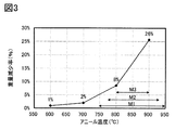
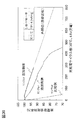
またフッ化物902の蒸発または昇華について図3を用いて説明する。図3はLiF:MgF2=1:3(モル比)となるように混合したフッ化物902について、容器に蓋をせずに、600℃、700℃、800℃および900℃で加熱したときの重量の減少率を示すグラフである。加熱は全て10時間、酸素雰囲気とした。
Further, the evaporation or sublimation of fluoride 902 will be described with reference to FIG. FIG. 3 shows the fluoride 902 mixed so that LiF: MgF 2 = 1: 3 (molar ratio) was heated at 600 ° C., 700 ° C., 800 ° C. and 900 ° C. without covering the container. It is a graph which shows the weight loss rate. All heating was performed in an oxygen atmosphere for 10 hours.
図3に示すように、加熱後の重量減少度が700℃では2%であったのに対し、800℃では8%、900℃では26%であった。このように800℃前後から急激にフッ化物902の蒸発または昇華が進むことが明らかとなった。
As shown in FIG. 3, the degree of weight loss after heating was 2% at 700 ° C., 8% at 800 ° C., and 26% at 900 ° C. As described above, it was clarified that the evaporation or sublimation of fluoride 902 rapidly progressed from around 800 ° C.
アニール温度は高い方が反応が進みやすく、アニール時間が短く済み、生産性が高く好ましい。
The higher the annealing temperature, the easier the reaction proceeds, the shorter the annealing time, and the higher the productivity, which is preferable.
ただしアニールする温度はLiCoO2の分解温度(1130℃)以下である必要がある。また、LiCoO2の分解温度は1130℃であるが、その近傍の温度では、微量ではあるがLiCoO2の分解が懸念される。そのため、アニール温度としては、1130℃以下であることが好ましく、1000℃以下であるとより好ましく、950℃(T4)以下であるとさらに好ましく、900℃(T3)以下であるとさらに好ましい。
However, the annealing temperature must be equal to or lower than the decomposition temperature of LiCoO 2 (1130 ° C.). Further, the decomposition temperature of LiCoO 2 is 1130 ° C., but at a temperature in the vicinity thereof, there is a concern that LiCoO 2 may be decomposed, albeit in a small amount. Therefore, the annealing temperature is preferably 1130 ° C. or lower, more preferably 1000 ° C. or lower, further preferably 950 ° C. (T4) or lower, and even more preferably 900 ° C. (T3) or lower.
よって、アニール温度としては、図3のM1に示すように850℃±100℃(750℃以上950℃以下)が好ましく、M2に示すように850℃±75℃(775℃以上925℃以下)がより好ましく、M3に示すように850℃±50℃(800℃以上900℃以下)が最も好ましい。
Therefore, the annealing temperature is preferably 850 ° C. ± 100 ° C. (750 ° C. or higher and 950 ° C. or lower) as shown in M1 of FIG. 3, and 850 ° C. ± 75 ° C. (775 ° C. or higher and 925 ° C. or lower) as shown in M2. More preferably, as shown in M3, 850 ° C. ± 50 ° C. (800 ° C. or higher and 900 ° C. or lower) is most preferable.
より詳細には、500℃以上1130℃以下が好ましく、500℃以上1000℃以下がより好ましく、500℃以上950℃以下がさらに好ましく、500℃以上900℃以下がさらに好ましい。また、742℃以上1130℃以下が好ましく、742℃以上1000℃以下がより好ましく、742℃以上950℃以下がさらに好ましく、742℃以上900℃以下がさらに好ましい。また、800℃以上1130℃以下が好ましく、800℃以上1000℃以下がより好ましく、800℃以上950℃以下がさらに好ましく、800℃(T2)以上900℃(T3)以下(範囲L)が最も好ましい。また、830℃以上1130℃以下が好ましく、830℃以上1000℃以下がより好ましく、830℃以上950℃以下がさらに好ましく、830℃以上900℃以下がさらに好ましい。
More specifically, 500 ° C. or higher and 1130 ° C. or lower is preferable, 500 ° C. or higher and 1000 ° C. or lower is more preferable, 500 ° C. or higher and 950 ° C. or lower is further preferable, and 500 ° C. or higher and 900 ° C. or lower is further preferable. Further, 742 ° C. or higher and 1130 ° C. or lower is preferable, 742 ° C. or higher and 1000 ° C. or lower is more preferable, 742 ° C. or higher and 950 ° C. or lower is further preferable, and 742 ° C. or higher and 900 ° C. or lower is further preferable. Further, 800 ° C. or higher and 1130 ° C. or lower is preferable, 800 ° C. or higher and 1000 ° C. or lower is more preferable, 800 ° C. or higher and 950 ° C. or lower is further preferable, and 800 ° C. (T2) or higher and 900 ° C. (T3) or lower (range L) is most preferable. .. Further, 830 ° C. or higher and 1130 ° C. or lower is preferable, 830 ° C. or higher and 1000 ° C. or lower is more preferable, 830 ° C. or higher and 950 ° C. or lower is further preferable, and 830 ° C. or higher and 900 ° C. or lower is further preferable.
より具体的には、フッ化物902としてLiFを用い、蓋をしてS16のアニールを行うことでサイクル特性などが良好な正極活物質904を作製できる。また、フッ化物902として、LiF及びMgF2を用いると、LiCoO2との反応が促進し、LiMO2が生成すると考えられる。
More specifically, LiF is used as the fluoride 902, the lid is closed, and S16 is annealed to prepare a positive electrode active material 904 having good cycle characteristics and the like. Further, when LiF and MgF 2 are used as the fluoride 902, it is considered that the reaction with LiCoO 2 is promoted and LiMO 2 is produced.
また、本実施の形態において、フッ化物であるLiFが融剤として機能すると考えられる。よって、加熱炉内部の容積が容器の容積に比べ大きく、酸素よりも軽いため、LiFが揮発し、混合物903中のLiFが減少するとLiMO2の生成が抑制されてしまうことが予想される。よって、LiFの揮発を抑制しつつ、加熱する必要がある。またLiFを用いなかったとしても、リチウム酸化物901表面のLiとFが反応して、LiFが生じ、揮発する可能性もある。そのため、LiFより融点が高いフッ化物を用いたとしても、同じように揮発の抑制が必要である。
Further, in the present embodiment, it is considered that LiF, which is a fluoride, functions as a flux. Therefore, since the volume inside the heating furnace is larger than the volume of the container and lighter than oxygen, it is expected that the formation of LiMO 2 will be suppressed when LiF volatilizes and the LiF in the mixture 903 decreases. Therefore, it is necessary to heat while suppressing the volatilization of LiF. Even if LiF is not used, Li and F on the surface of lithium oxide 901 may react to generate LiF and volatilize. Therefore, even if a fluoride having a melting point higher than that of LiF is used, it is necessary to suppress volatilization in the same manner.
そこで、LiFを含む雰囲気で混合物903を加熱すること、すなわち、加熱炉内のLiFの分圧が高い状態で混合物903を加熱することによって、混合物903中のLiFの揮発を抑制する。共融させた混合物を形成するためのフッ化物(LiFまたはMgF)を用いて蓋をしてアニールすることで、アニール温度をLiCoO2の分解温度(1130℃)以下、具体的には742℃以上1000℃以下にまで低温化でき、LiMO2の生成を効率よく進行させることができる。そのため、特性が良好な正極活物質を作製でき、さらにアニール時間も短縮することができる。
Therefore, by heating the mixture 903 in an atmosphere containing LiF, that is, by heating the mixture 903 in a state where the partial pressure of LiF in the heating furnace is high, volatilization of LiF in the mixture 903 is suppressed. By covering and annealing with a fluoride (LiF or MgF) for forming a eutectic mixture, the annealing temperature is set to the decomposition temperature of LiCoO 2 (1130 ° C.) or lower, specifically 742 ° C. or higher. The temperature can be lowered to 1000 ° C. or lower, and the production of LiMO 2 can proceed efficiently. Therefore, a positive electrode active material having good characteristics can be produced, and the annealing time can be shortened.
S16におけるアニール方法の一例を図5に示す。
An example of the annealing method in S16 is shown in FIG.
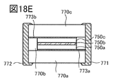
図5に示す加熱炉120は加熱炉内空間102、熱板104、ヒーター部106及び断熱材108を有する。容器116に蓋118を配してアニールするとより好ましい。該構成とすることによって、容器116及び蓋118で構成される空間119内をフッ化物を含む雰囲気にすることができる。アニール中は、空間119内のガス化されたフッ化物の濃度が一定または低減しないように蓋をすることで状態を維持すると、粒子表面近傍にフッ素およびマグネシウムを含ませることができる。空間119は加熱炉内空間102よりも容積が小さいため、少量のフッ化物が揮発することで、フッ化物を含む雰囲気とすることができる。すなわち、混合物903に含まれるフッ化物の量を大きく損なうことなく反応系をフッ化物を含む雰囲気にすることができる。そのため、効率よくLiMO2が生成を生成させることができる。また、蓋118を用いることによって簡便かつ安価にフッ化物を含む雰囲気で混合物903をアニールすることができる。
The heating furnace 120 shown in FIG. 5 has a space inside the heating furnace 102, a hot plate 104, a heater unit 106, and a heat insulating material 108. It is more preferable to arrange the lid 118 on the container 116 and anneal it. With this configuration, the space 119 composed of the container 116 and the lid 118 can have an atmosphere containing fluoride. During annealing, if the state is maintained by covering the space 119 so that the concentration of gasified fluoride is not constant or reduced, fluorine and magnesium can be contained in the vicinity of the particle surface. Since the space 119 has a smaller volume than the space 102 in the heating furnace, a small amount of fluoride volatilizes to create an atmosphere containing fluoride. That is, the reaction system can have a fluoride-containing atmosphere without significantly impairing the amount of fluoride contained in the mixture 903. Therefore, LiMO 2 can efficiently generate production. Further, by using the lid 118, the mixture 903 can be easily and inexpensively annealed in an atmosphere containing fluoride.
ここで、本発明の一態様によって作製されるLiMO2中のCo(コバルト)の価数はおおむね3価であることが好ましい。コバルトは2価及び3価をとり得る。そのため、コバルトの還元を抑制するために、加熱炉内空間102の雰囲気は酸素を含むと好ましく、加熱炉内空間102の雰囲気中の酸素と窒素の比率が大気雰囲気以上であるとより好ましく、加熱炉内空間102の雰囲気における酸素濃度は大気雰囲気以上であるとさらに好ましい。よって、加熱炉内空間に酸素を含む雰囲気を導入する必要がある。ただし、近くにマグネシウム原子が存在するコバルト原子については2価である方が安定である可能性があるため、全てのコバルト原子が3価でなくてもよい。
Here, it is preferable that the valence of Co (cobalt) in LiMO 2 produced by one aspect of the present invention is approximately trivalent. Cobalt can be divalent and trivalent. Therefore, in order to suppress the reduction of cobalt, the atmosphere of the heating furnace space 102 preferably contains oxygen, and the ratio of oxygen and nitrogen in the atmosphere of the heating furnace space 102 is more preferably equal to or higher than the atmosphere atmosphere, and heating is performed. It is more preferable that the oxygen concentration in the atmosphere of the furnace space 102 is equal to or higher than the atmosphere atmosphere. Therefore, it is necessary to introduce an atmosphere containing oxygen into the space inside the heating furnace. However, all cobalt atoms do not have to be trivalent because a cobalt atom having a magnesium atom nearby may be more stable if it is divalent.
そこで、本発明の一態様では、加熱を行う前に、加熱炉内空間102を、酸素を含む雰囲気にする工程及び混合物903を入れた容器116を加熱炉内空間102に設置する工程を行う。該工程の順序とすることで、混合物903を酸素及びフッ化物を含む雰囲気でアニールすることができる。また、アニール中は加熱炉内空間102を密閉し、ガスが外部に運ばれないようにすることが好ましい。例えば、アニール中はガスをフローしないで行うと好ましい。
Therefore, in one aspect of the present invention, before heating, the step of making the heating furnace space 102 into an atmosphere containing oxygen and the step of installing the container 116 containing the mixture 903 in the heating furnace space 102 are performed. By following the order of the steps, the mixture 903 can be annealed in an atmosphere containing oxygen and fluoride. Further, it is preferable to seal the space 102 in the heating furnace during annealing so that the gas is not carried to the outside. For example, it is preferable to perform annealing without flowing gas.
加熱炉内空間102を、酸素を含む雰囲気にする方法は特に制限はないが、一例として加熱炉内空間102を排気した後、酸素ガスまたは乾燥空気等酸素を含む気体を導入する方法、酸素ガスまたは乾燥空気等酸素を含む気体を一定時間流入する方法が挙げられる。中でも、加熱炉内空間102を排気した後、酸素ガスを導入する(酸素置換)を行うと好ましい。なお、加熱炉内空間102の大気を、酸素を含む雰囲気とみなしても構わない。
The method of creating an atmosphere containing oxygen in the heating furnace space 102 is not particularly limited, but as an example, a method of introducing a gas containing oxygen such as oxygen gas or dry air after exhausting the heating furnace space 102, oxygen gas. Alternatively, a method of inflowing a gas containing oxygen such as dry air for a certain period of time can be mentioned. Above all, it is preferable to introduce oxygen gas (oxygen substitution) after exhausting the space 102 in the heating furnace. The atmosphere in the heating furnace space 102 may be regarded as an atmosphere containing oxygen.
容器116に蓋118を配し、酸素を含む雰囲気としてから加熱すると、容器116に配した蓋118の隙間から適度な量の酸素が容器116内に入り、かつフッ化物を適度な量、容器116内に留めることができる。
When the lid 118 is placed in the container 116 to create an atmosphere containing oxygen and then heated, an appropriate amount of oxygen enters the container 116 through the gap of the lid 118 arranged in the container 116, and an appropriate amount of fluoride is added to the container 116. Can be kept inside.
また、容器116および蓋118の内壁に付着したフッ化物等が、加熱により再飛翔して混合物903に付着する可能性もある。
In addition, fluoride or the like adhering to the inner walls of the container 116 and the lid 118 may re-fly by heating and adhere to the mixture 903.
加熱炉120を加熱する工程として特に制限はない。加熱炉120に備えられている加熱機構を用いて加熱すればよい。
The step of heating the heating furnace 120 is not particularly limited. It may be heated by using the heating mechanism provided in the heating furnace 120.
また、容器116へ入れた際の混合物903の配し方に特に制限はないが、図5に示すように、容器116の底面に対して、混合物903の上面が平らになるように、言い換えると混合物903の上面の高さが均一になるように混合物903を配すると好ましい。
Further, there is no particular limitation on how to arrange the mixture 903 when it is put into the container 116, but in other words, as shown in FIG. 5, the upper surface of the mixture 903 is flat with respect to the bottom surface of the container 116. It is preferable to arrange the mixture 903 so that the height of the upper surface of the mixture 903 is uniform.
上記ステップS16のアニールは、適切な温度および時間で行うことが好ましい。適切な温度および時間は、ステップS11のリチウム酸化物901の粒子の大きさおよび組成等の条件により変化する。粒子が小さい場合は、大きい場合よりも低い温度または短い時間がより好ましい場合がある。S16のアニール後に蓋をとる工程を有する。
The annealing in step S16 is preferably performed at an appropriate temperature and time. The appropriate temperature and time vary depending on conditions such as the particle size and composition of the lithium oxide 901 in step S11. Smaller particles may be more preferred at lower temperatures or shorter times than larger particles. It has a step of removing the lid after annealing S16.
例えばステップS11の粒子のD50が12μm程度の場合、アニール時間は例えば3時間以上が好ましく、10時間以上がより好ましい。
For example, when the D50 of the particles in step S11 is about 12 μm, the annealing time is preferably, for example, 3 hours or more, and more preferably 10 hours or more.
一方、ステップS11の粒子のD50が5μm程度の場合、アニール時間は例えば1時間以上10時間以下が好ましく、2時間程度がより好ましい。
On the other hand, when the D50 of the particles in step S11 is about 5 μm, the annealing time is preferably, for example, 1 hour or more and 10 hours or less, and more preferably about 2 hours.
アニール後の降温時間は、例えば10時間以上50時間以下とすることが好ましい。
The temperature lowering time after annealing is preferably, for example, 10 hours or more and 50 hours or less.
上記でアニールした材料を回収し(図4のステップS17)、正極活物質904を得る(図4のステップS18)。
The material annealed above is recovered (step S17 in FIG. 4) to obtain a positive electrode active material 904 (step S18 in FIG. 4).
ここで、S16のアニールの際に、蓋ありでアニールした場合と、蓋なしでアニールした比較例との得られた粒子の差を以下に説明する。
Here, the difference between the obtained particles in the case of annealing with a lid and the comparative example of annealing without a lid in the annealing of S16 will be described below.
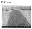
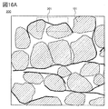
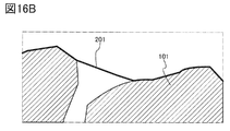
図6Aは、蓋ありでアニールして正極活物質粒子の一つに対してSTEMで得られた断面写真の一例である。また、図6Bは、蓋なしでアニールして正極活物質粒子の一つに対してSTEMで得られた断面写真の一例である。なお、図6A及び図6Bにおいて、正極活物質粒子の周りは樹脂となっており、保護膜を形成した後でSTEM観察している。
FIG. 6A is an example of a cross-sectional photograph obtained by STEM for one of the positive electrode active material particles by annealing with a lid. Further, FIG. 6B is an example of a cross-sectional photograph obtained by STEM for one of the positive electrode active material particles by annealing without a lid. In addition, in FIGS. 6A and 6B, the area around the positive electrode active material particles is made of resin, and STEM observation is performed after forming the protective film.
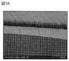
さらに得られた写真図6Aの一部を拡大した図が図7Aである。また、比較例である図6Bの一部を拡大した図が図7Bである。図7Aの粒子表面のほうが、図7Bに比べて滑らか、またはツルツルまたはツヤツヤである状態が判断できる。
FIG. 7A is an enlarged view of a part of the obtained photograph FIG. 6A. Further, an enlarged view of a part of FIG. 6B, which is a comparative example, is shown in FIG. 7B. It can be determined that the particle surface of FIG. 7A is smoother, smoother or glossier than that of FIG. 7B.
この粒子表面の差を明確にするため、粒子表面の凹凸を定量化するための手法及び手順を以下に示す。
In order to clarify the difference in the particle surface, the method and procedure for quantifying the unevenness of the particle surface are shown below.
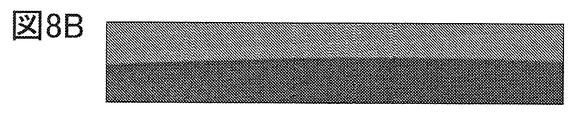
図8Aは図6Aと同一である。図8A中の点線で囲まれた領域を拡大し、切り取った画像が図8Bである。本実施の形態では、点線で囲んだ領域を、粒子のラフネスを求める領域としてトリミングを行う。図8Bの画像の上部は、STEM観察のために形成した保護膜の樹脂であり、画像の下部が正極活物質粒子となっており、界面が粒子表面最外殻を示している。
FIG. 8A is the same as FIG. 6A. An enlarged and cropped image of the area surrounded by the dotted line in FIG. 8A is shown in FIG. 8B. In the present embodiment, the region surrounded by the dotted line is trimmed as a region for obtaining the roughness of the particles. The upper part of the image of FIG. 8B is the resin of the protective film formed for STEM observation, the lower part of the image is the positive electrode active material particles, and the interface shows the outermost shell on the particle surface.
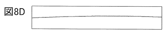
図8Bのノイズ処理を行うため、ガウスぼかし(σ=2)を行った後、二値化を行う際、画像処理ソフトを用いる。二値化を行った後の画像が図8Cである。そして、さらに画像処理ソフトを用いて界面抽出を行うと、図8Dが得られる。 なおノイズ処理、界面抽出等を行う画像処理ソフトについては特に限定されないが、例えば「ImageJ」を用いることができる。また表計算ソフト等についても特に限定されないが、例えばMicrosoft Office Excelを用いることができる。
In order to perform the noise processing of FIG. 8B, image processing software is used when performing binarization after performing Gaussian blurring (σ = 2). The image after binarization is shown in FIG. 8C. Then, when the interface is further extracted using image processing software, FIG. 8D is obtained. The image processing software that performs noise processing, interface extraction, etc. is not particularly limited, but for example, "ImageJ" can be used. Further, the spreadsheet software and the like are not particularly limited, but for example, Microsoft Office Excel can be used.
図8Dの画像データをmagic handツールで目的の境界ラインを選択し、データをExcelに抽出する。Excelに抽出された数値データをグラフ化すると図8Eとすることができる。
Select the target boundary line with the magic hand tool for the image data of FIG. 8D, and extract the data into Excel. The numerical data extracted in Excel can be graphed as FIG. 8E.
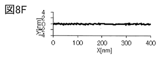
Excelの機能を用いて、回帰直線(二次回帰)から補正を行い、傾き補正後データからラフネス算出用パラメータを求める。傾き補正後データを絶対値にし、平均を出した後、その平均の平方根をRMSとして図8Fに示している。この表面粗さは、標準偏差を算出したRMSである。また、この表面粗さは、正極活物質の少なくとも粒子外周の400nmにおける表面粗さである。
Using the Excel function, correction is performed from the regression line (secondary regression), and the parameters for calculating roughness are obtained from the data after slope correction. After the tilt-corrected data is set to an absolute value and averaged, the square root of the average is shown as RMS in FIG. 8F. This surface roughness is the RMS for which the standard deviation is calculated. Further, this surface roughness is the surface roughness of at least the outer circumference of the particles of the positive electrode active material at 400 nm.
本実施の形態の正極活物質の粒子表面においては、ラフネスの指標である粗さ(RMS)は0.1nmと求めることができる。フッ化物と混合した後に蓋をして加熱することで表面改質が行われ、その結果、3nm未満、好ましくは1nm未満、さらに好ましくは0.5nm未満のRMSである正極活物質とすることが容易となる。
On the particle surface of the positive electrode active material of the present embodiment, the roughness (RMS), which is an index of roughness, can be determined to be 0.1 nm. After mixing with fluoride, the surface is modified by covering and heating to obtain a positive electrode active material having an RMS of less than 3 nm, preferably less than 1 nm, and more preferably less than 0.5 nm. It will be easy.
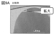
また、比較例でも同様のRMS算出を行うと、図9Aは図6Bと同一であり、図9Aの点線で囲まれた領域をトリミングした画像データが図9Bである。上述の方法と同じ手順で数値データをグラフ化すると図9Cとすることができる。また、比較例の粒子表面においては、ラフネスの指標である粗さ(RMS)は3.3nmと求めることができる。
Further, when the same RMS calculation is performed in the comparative example, FIG. 9A is the same as FIG. 6B, and the image data obtained by trimming the area surrounded by the dotted line in FIG. 9A is shown in FIG. 9B. When the numerical data is graphed by the same procedure as the above method, FIG. 9C can be obtained. Further, on the particle surface of the comparative example, the roughness (RMS), which is an index of roughness, can be determined to be 3.3 nm.
(実施の形態2)
本実施の形態では、本発明の一態様の作製方法によって作製したLiMO2を用いて電池セルを作製する例を示す。なお、共通する部分が多いため、作製方法は図4を用いて説明する。
(Embodiment 2)
In this embodiment, an example of producing a battery cell using LiMO 2 produced by the production method of one aspect of the present invention is shown. Since there are many common parts, the manufacturing method will be described with reference to FIG.
リチウム酸化物901として、コバルト酸リチウムを準備する。より具体的には、日本化学工業株式会社製のセルシードC−10Nを準備する(ステップS11)。
Lithium cobalt oxide is prepared as lithium oxide 901. More specifically, CellSeed C-10N manufactured by Nippon Chemical Industrial Co., Ltd. is prepared (step S11).
フッ化物902として、LiFとMgF2を準備する。LiFとMgF2のモル比が、LiF:MgF2=1:3となるよう秤量し、溶媒としてアセトンを加えて湿式で混合および粉砕をする。コバルト酸リチウムに対してLiFが0.17mol%となるようにする。また、コバルト酸リチウムに対してMgF2が0.5mol%となるようにする。
LiF and MgF 2 are prepared as fluoride 902. Weigh the mixture so that the molar ratio of LiF and MgF 2 is LiF: MgF 2 = 1: 3, add acetone as a solvent, and mix and grind in a wet manner. LiF is adjusted to 0.17 mol% with respect to lithium cobalt oxide. Further, MgF 2 is adjusted to 0.5 mol% with respect to lithium cobalt oxide.
リチウム酸化物901とフッ化物902を混合し、回収し、混合物903を得る。
Lithium oxide 901 and fluoride 902 are mixed and recovered to give the mixture 903.
次いで、混合物903を容器に入れ、蓋をし、加熱炉内を酸素雰囲気としてアニールを行う。アニール温度は、混合物903の重量によっても異なる場合もあるが、742℃以上1000℃以下とすることが好ましい。「アニール温度」はアニールを行った際の温度であり、「アニール時間」はアニール温度を保持した時間である。昇温は200℃/hとし、降温は10時間以上かけて行う。また、アニール中はガスの供給を積極的に行わず、気体のフッ化物が外部に運ばれるのを抑えることが好ましい。例えば、アニール中はガスをフローしないで行うと好ましい。
Next, the mixture 903 is placed in a container, covered, and annealed with the inside of the heating furnace as an oxygen atmosphere. The annealing temperature may vary depending on the weight of the mixture 903, but is preferably 742 ° C. or higher and 1000 ° C. or lower. The "annealing temperature" is the temperature at which the annealing is performed, and the "annealing time" is the time during which the annealing temperature is maintained. The temperature rise is 200 ° C./h, and the temperature is lowered over 10 hours or more. Further, it is preferable not to positively supply the gas during annealing to prevent the gaseous fluoride from being carried to the outside. For example, it is preferable to perform annealing without flowing gas.
本実施の形態では、アニール温度850℃、60時間、加熱炉内を酸素雰囲気とする。
In the present embodiment, the annealing temperature is 850 ° C., 60 hours, and the inside of the heating furnace is set to an oxygen atmosphere.
アニール後は、回収して正極活物質904を得ることができる。凹凸のない表面が得られていれば、加熱中に蓋を取って冷却してもよい。冷却後は蓋を取り、得られた正極活物質904を用い、各々の正極を作製する。正極活物質、ABおよびPVDFを活物質:AB:PVDF=95:3:2(重量比)で混合したスラリーを集電体に塗工したものを用いる。スラリーの溶媒としてNMPを用いる。
After annealing, it can be recovered to obtain the positive electrode active material 904. If a smooth surface is obtained, the lid may be removed during heating to cool the surface. After cooling, the lid is removed, and the obtained positive electrode active material 904 is used to prepare each positive electrode. A slurry obtained by mixing the positive electrode active material, AB and PVDF in an active material: AB: PVDF = 95: 3: 2 (weight ratio) is applied to the current collector. NMP is used as the solvent for the slurry.
集電体にスラリーを塗工した後、溶媒を蒸発させる。その後、210kN/mで加圧を行った後、さらに1467kN/mで加圧を行った。以上の工程により、正極を得る。正極の担持量はおよそ7mg/cm2、正極活物質の密度は>3.8g/ccとする。
After applying the slurry to the current collector, the solvent is evaporated. Then, after pressurizing at 210 kN / m, further pressurizing was performed at 1467 kN / m. A positive electrode is obtained by the above steps. The amount supported by the positive electrode is approximately 7 mg / cm 2 , and the density of the positive electrode active material is> 3.8 g / cc.
作製した正極を用いて、CR2032タイプ(直径20mm、高さ3.2mm)のコイン型の電池セルを作製する。
Using the prepared positive electrode, a CR2032 type (diameter 20 mm, height 3.2 mm) coin-shaped battery cell is manufactured.
対極にはリチウム金属を用いる。
Lithium metal is used as the counter electrode.
電解液が有する電解質には、1mol/Lの六フッ化リン酸リチウム(LiPF6)を用い、電解液には、エチレンカーボネート(EC)とジエチルカーボネート(DEC)がEC:DEC=3:7(体積比)で混合されたものを用いる。なお、電解液に添加剤としてビニレンカーボネート(VC)を2wt%添加する。
1 mol / L lithium hexafluorophosphate (LiPF 6 ) was used as the electrolyte contained in the electrolytic solution, and ethylene carbonate (EC) and diethyl carbonate (DEC) were used as the electrolytic solution in EC: DEC = 3: 7 ( Use the one mixed by volume ratio). In addition, 2 wt% of vinylene carbonate (VC) is added to the electrolytic solution as an additive.
セパレータには厚さ25μmのポリプロピレンを用いる。
Polypropylene having a thickness of 25 μm is used for the separator.
正極缶及び負極缶には、ステンレス(SUS)で形成されているものを用いる。
As the positive electrode can and the negative electrode can, those made of stainless steel (SUS) are used.
以上の工程により、二次電池のセルを作製することができる。
By the above steps, a cell of a secondary battery can be manufactured.
以下に、アニール時の条件を変えて比較した実験結果を示す。
The experimental results for comparison under different conditions at the time of annealing are shown below.
図10Aは、上記作製方法と同一の条件1として示しており、図5と同一であるため、図5と同じ符号を用いる。また、条件2として図10Bに示すように蓋を4枚使用する。また、条件3として図10Cに示すように容器と蓋をそれぞれ用いて3重とする。蓋と容器は同じ素材、具体的にはセラミックス材料を用いる。蓋は容器の開口よりも大きく、自重で載せられる。蓋と容器との隙間はできるだけないほうが好ましいが、容器内が蓋で密閉とならないように隙間を有している。条件1、条件2、条件3は、図10で示す条件の違い以外は全て同じ手順、条件としている。
FIG. 10A shows the same condition 1 as the above-mentioned manufacturing method, and since it is the same as FIG. 5, the same reference numerals as those in FIG. 5 are used. Further, as condition 2, four lids are used as shown in FIG. 10B. Further, as condition 3, as shown in FIG. 10C, a container and a lid are used, respectively, to make a triple. The same material is used for the lid and the container, specifically ceramic material. The lid is larger than the opening of the container and can be placed by its own weight. It is preferable that there is as little gap between the lid and the container as possible, but there is a gap so that the inside of the container is not sealed by the lid. Condition 1, condition 2, and condition 3 all have the same procedure and conditions except for the difference in the conditions shown in FIG.
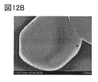
それぞれの条件1、2、3で同じアニールを行い、得られた粒子のSEM写真を図12A、図12B、図12Cに示す。条件1が図12Aであり、条件2が図12Bであり、条件3が図12Cである。いずれの条件も蓋があれば、それぞれの活物質粒子の表面がクラックまたは凸部がほとんどなく、SEM写真で観察した時に表面がツルツルしている、またはツヤツヤしている状態となっていることが確認できている。平坦性、即ち、表面に凹凸のないようにするにはフッ素が重要であり、フッ素がガスとして外部に放出されることを防ぐために蓋をすることで、粒子表面にきれいな結合を作る。また、フッ素を表面近傍に含ませることによって、フッ素だけでなく、マグネシウムを高濃度に表面近傍に配することができる。
The same annealing was performed under the respective conditions 1, 2 and 3, and SEM photographs of the obtained particles are shown in FIGS. 12A, 12B and 12C. Condition 1 is FIG. 12A, condition 2 is FIG. 12B, and condition 3 is FIG. 12C. Under either condition, if there is a lid, the surface of each active material particle has almost no cracks or protrusions, and the surface is smooth or glossy when observed by SEM photographs. I have confirmed it. Fluorine is important for flatness, that is, to prevent the surface from being uneven, and by covering it with a lid to prevent fluorine from being released to the outside as a gas, a clean bond is formed on the particle surface. Further, by including fluorine in the vicinity of the surface, not only fluorine but also magnesium can be arranged in the vicinity of the surface at a high concentration.
条件1の図12Aの粒子の一部をEDXで測定したところ、粒子の表面近傍にマグネシウムのピークを確認できる。EDXの結果を図13Aに示す。図13Aの横軸は深さ方向(Distance)を示している。コバルトの検出位置付近が粒子の最外殻の位置と判断できることから、粒子の表面近傍にマグネシウムのピークを確認できる。また、図12Bの粒子の一部のEDX測定結果が図13Bである。また、図12Cの粒子の一部のEDX測定結果が図13Cである。いずれの条件のEDX結果であってもすべて正極活物質粒子の表面にマグネシウムの偏在を確認できる。この粒子の表面近傍のマグネシウムは、放電時にLiが脱離しても結晶構造(層状岩塩型の結晶構造)を維持する機能を有している。なお、EDXの結果では表面のみにマグネシウムのピークが確認できているが、勿論、粒子内部にマグネシウムは含まれている。また、高電圧の充放電の繰り返しにおいて、CoO2層のずれを小さくすることができる。さらに、充放電の繰り返しにおいて、体積の変化を小さくすることができる。従って、このような特徴を有する正極活物質を用いた二次電池は、サイクル特性が大幅に向上する。
When a part of the particles in FIG. 12A of Condition 1 was measured by EDX, a magnesium peak could be confirmed near the surface of the particles. The result of EDX is shown in FIG. 13A. The horizontal axis of FIG. 13A indicates the depth direction (Distance). Since it can be determined that the position near the detection position of cobalt is the position of the outermost shell of the particle, the peak of magnesium can be confirmed near the surface of the particle. Further, the EDX measurement result of a part of the particles of FIG. 12B is shown in FIG. 13B. Further, the EDX measurement result of a part of the particles of FIG. 12C is shown in FIG. 13C. Regardless of the EDX result under any condition, the uneven distribution of magnesium can be confirmed on the surface of the positive electrode active material particles. Magnesium near the surface of these particles has a function of maintaining a crystal structure (layered rock salt type crystal structure) even if Li is desorbed during discharge. In the EDX result, a magnesium peak can be confirmed only on the surface, but of course, magnesium is contained inside the particles. Further, the deviation of the CoO 2 layer can be reduced in the repeated charging and discharging of the high voltage. Further, the change in volume can be reduced by repeating charging and discharging. Therefore, the cycle characteristics of the secondary battery using the positive electrode active material having such characteristics are significantly improved.
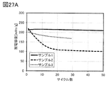
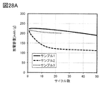
条件1、条件2、条件3の電池セルのサイクル特性を図11に示す。充電をCCCV(0.5C、4.6V、終止電流0.05C)、放電をCC(0.5C、2.5V)として25℃においてサイクル特性を評価した。その結果を図11に示す。
FIG. 11 shows the cycle characteristics of the battery cells under conditions 1, 2, and 3. The cycle characteristics were evaluated at 25 ° C. with CCCV (0.5C, 4.6V, termination current 0.05C) for charging and CC (0.5C, 2.5V) for discharging. The result is shown in FIG.
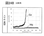
また、図11には、比較例として図10Dに示すように、蓋なしの条件で、その他の作製手順、条件を条件1と同じとして電池セルを作製した場合の、サイクル特性を示している。また、比較例の粒子のSEM写真を図24Aに示す。SEM写真では、比較例の粒子表面は、ざらざらの見た目の印象を受ける。表面に細かい凸部が多数視認することができ、条件1、2、3の結果とは、大きく異なっている。また、図24Aの粒子の一部のEDX測定結果を図24Bに示す。図24Bの横軸は距離(Distance)である。比較例での蓋なしの条件では、マグネシウムのピークは見られない。蓋なしのアニールを行った比較例の場合、フッ素が粒子内部から外部に放出され、表面にマグネシウムがほとんど存在しないことから、充放電を行った場合、歪みに起因する結晶構造の崩れが生じるため、図11に示すようにサイクル特性が低下しているといえる。
Further, as shown in FIG. 10D as a comparative example, FIG. 11 shows the cycle characteristics when a battery cell is manufactured under the condition without a lid under the same conditions as the condition 1 and other manufacturing procedures. Moreover, the SEM photograph of the particle of the comparative example is shown in FIG. 24A. In the SEM photograph, the particle surface of the comparative example gives an impression of a rough appearance. A large number of fine protrusions can be visually recognized on the surface, which is significantly different from the results of conditions 1, 2, and 3. Further, the EDX measurement results of some of the particles of FIG. 24A are shown in FIG. 24B. The horizontal axis of FIG. 24B is the distance. Under the condition without a lid in the comparative example, no magnesium peak is observed. In the case of the comparative example in which the annealing was performed without a lid, fluorine was released from the inside of the particles to the outside, and magnesium was hardly present on the surface. Therefore, when charging / discharging was performed, the crystal structure collapsed due to strain. , It can be said that the cycle characteristics are deteriorated as shown in FIG.
以上より、蓋なしのアニール条件の比較例に比べて、蓋ありのアニール条件(条件1、条件2、及び条件3)は、良好なサイクル特性を示すことが確認できる。
From the above, it can be confirmed that the annealing conditions with a lid (Condition 1, Condition 2, and Condition 3) exhibit better cycle characteristics as compared with the comparative example of the annealing conditions without a lid.
(実施の形態3)
本実施の形態では、本発明の一態様の作製方法によって作製された正極活物質の構造の一例について説明する。
(Embodiment 3)
In the present embodiment, an example of the structure of the positive electrode active material produced by the production method of one aspect of the present invention will be described.
[正極活物質の構造]
コバルト酸リチウム(LiCoO2)などの層状岩塩型の結晶構造を有する材料は、放電容量が高く、二次電池の正極活物質として優れることが知られている。層状岩塩型の結晶構造を有する材料として例えば、LiMO2で表される複合酸化物が挙げられる。元素Mの一例としてCo、Ni、Mnより選ばれる一以上が挙げられる。また、元素Mの一例としてCo、Ni、Mnより選ばれる一以上に加えて、AlおよびMgより選ばれる一以上が挙げられる。
[Structure of positive electrode active material]
A material having a layered rock salt type crystal structure such as lithium cobalt oxide (LiCoO 2 ) has a high discharge capacity and is known to be excellent as a cathode active material for a secondary battery. Examples of the material having a layered rock salt type crystal structure include a composite oxide represented by LiMO 2. As an example of the element M, one or more selected from Co, Ni, and Mn can be mentioned. Further, as an example of the element M, in addition to one or more selected from Co, Ni, and Mn, one or more selected from Al and Mg can be mentioned.
遷移金属化合物におけるヤーン・テラー効果は、遷移金属のd軌道の電子の数により、その効果の強さが異なることが知られている。
It is known that the strength of the Jahn-Teller effect in a transition metal compound differs depending on the number of electrons in the d-orbital of the transition metal.
ニッケルを有する化合物においては、ヤーン・テラー効果により歪みが生じやすい場合がある。よって、LiNiO2において高電圧における充放電を行った場合、歪みに起因する結晶構造の崩れが生じる懸念がある。LiCoO2においてはヤーン・テラー効果の影響が小さいことが示唆され、高電圧における充放電の耐性がより優れる場合があり好ましい。
In a compound having nickel, distortion may easily occur due to the Jahn-Teller effect. Therefore, when charging and discharging the LiNiO 2 at a high voltage, there is a concern that the crystal structure may collapse due to distortion. It is suggested that the influence of the Jahn-Teller effect is small in LiCoO 2 , and it is preferable that the charge / discharge resistance at a high voltage may be better.
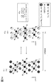
図14および図15を用いて、正極活物質について説明する。図14および図15では、正極活物質が有する遷移金属としてコバルトを用いる場合について述べる。
The positive electrode active material will be described with reference to FIGS. 14 and 15. 14 and 15 show a case where cobalt is used as the transition metal contained in the positive electrode active material.
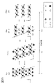
<従来の正極活物質>
図15に示す正極活物質は、ハロゲン及びマグネシウムが添加されないコバルト酸リチウム(LiCoO2)である。図15に示すコバルト酸リチウムは、充電深度によって結晶構造が変化する。
<Conventional positive electrode active material>
The positive electrode active material shown in FIG. 15 is lithium cobalt oxide (LiCoO 2 ) to which halogen and magnesium are not added. The crystal structure of lithium cobalt oxide shown in FIG. 15 changes depending on the charging depth.
図15に示すように、充電深度0(放電状態)であるコバルト酸リチウムは、空間群R−3mの結晶構造を有する領域を有し、ユニットセル中にCoO2層が3層存在する。そのためこの結晶構造を、O3型結晶構造と呼ぶ場合がある。なお、CoO2層とはコバルトに酸素が6配位した8面体構造が、稜共有の状態で平面に連続した構造をいうこととする。
As shown in FIG. 15, lithium cobalt oxide having a charging depth of 0 (discharged state) has a region having a crystal structure of the space group R-3 m, and three CoO 2 layers are present in the unit cell. Therefore, this crystal structure may be referred to as an O3 type crystal structure. The CoO 2 layer is a structure in which an octahedral structure in which oxygen is coordinated to cobalt is continuous with a plane in a state of sharing a ridge.
また充電深度1のときは、空間群P−3m1の結晶構造を有し、ユニットセル中にCoO2層が1層存在する。そのためこの結晶構造を、O1型結晶構造と呼ぶ場合がある。
When the charging depth is 1, the space group P-3m1 has a crystal structure, and one CoO 2 layer exists in the unit cell. Therefore, this crystal structure may be referred to as an O1 type crystal structure.
また充電深度が0.88程度のときのコバルト酸リチウムは、空間群R−3mの結晶構造を有する。この構造は、P−3m1(O1)のようなCoO2の構造と、R−3m(O3)のようなLiCoO2の構造と、が交互に積層された構造ともいえる。そのためこの結晶構造を、H1−3型結晶構造と呼ぶ場合がある。なお、実際にはH1−3型結晶構造は、ユニットセルあたりのコバルト原子の数が他の構造の2倍となっている。しかし図15をはじめ本明細書では、他の構造と比較しやすくするためH1−3型結晶構造のc軸をユニットセルの1/2にした図で示すこととする。
Lithium cobalt oxide when the charging depth is about 0.88 has a crystal structure of the space group R-3 m. This structure can be said to be a structure in which a structure of CoO 2 such as P-3m1 (O1) and a structure of LiCoO 2 such as R-3m (O3) are alternately laminated. Therefore, this crystal structure may be referred to as an H1-3 type crystal structure. Actually, in the H1-3 type crystal structure, the number of cobalt atoms per unit cell is twice that of other structures. However, in this specification including FIG. 15, in order to make it easier to compare with other structures, the c-axis of the H1-3 type crystal structure is shown in a diagram in which the c-axis is halved of the unit cell.
H1−3型結晶構造は一例として、ユニットセルにおけるコバルトと酸素の座標を、Co(0、0、0.42150±0.00016)、O1(0、0、0.27671±0.00045)、O2(0、0、0.11535±0.00045)と表すことができる。O1及びO2はそれぞれ酸素原子である。このようにH1−3型結晶構造は、1つのコバルト及び2つの酸素を用いたユニットセルにより表される。一方、後述するように、本発明の一態様のO3’型結晶構造は好ましくは、1つのコバルト及び1つの酸素を用いたユニットセルにより表される。これは、O3’型結晶構造の場合とH1−3型構造の場合では、コバルトと酸素との対称性が異なり、O3’型結晶構造の方が、H1−3型構造に比べてO3の構造からの変化が小さいことを示す。正極活物質が有する結晶構造をいずれのユニットセルを用いて表すのがより好ましいか、の選択は例えば、XRDのリートベルト解析において、GOF(goodness of fit)の値がより小さくなるように選択すればよい。
As an example of the H1-3 type crystal structure, the coordinates of cobalt and oxygen in the unit cell are set to Co (0, 0, 0.42150 ± 0.00016) and O 1 (0, 0, 0.27671 ± 0.00045). , O 2 (0, 0, 0.11535 ± 0.00045). O 1 and O 2 are oxygen atoms, respectively. As described above, the H1-3 type crystal structure is represented by a unit cell using one cobalt and two oxygens. On the other hand, as will be described later, the O3'type crystal structure of one aspect of the present invention is preferably represented by a unit cell using one cobalt and one oxygen. This is because the symmetry of cobalt and oxygen differs between the O3'type crystal structure and the H1-3 type structure, and the O3'type crystal structure has an O3 structure compared to the H1-3 type structure. Indicates that the change from is small. It is more preferable to use which unit cell to represent the crystal structure of the positive electrode active material. For example, in the Rietveld analysis of XRD, the GOF (goodness of fit) value should be selected to be smaller. Just do it.
充電電圧がリチウム金属の酸化還元電位を基準に4.6V以上になるような高電圧の充電、あるいは充電深度が0.8以上になるような深い深度の充電と、放電とを繰り返すと、コバルト酸リチウムはH1−3型結晶構造と、放電状態のR−3m(O3)の構造と、の間で結晶構造の変化(つまり、非平衡な相変化)を繰り返すことになる。
When high-voltage charging such that the charging voltage becomes 4.6 V or more based on the oxidation-reduction potential of lithium metal, or deep charging such that the charging depth becomes 0.8 or more, and discharging are repeated, cobalt Lithium acid acid repeats a change in crystal structure (that is, a non-equilibrium phase change) between the H1-3 type crystal structure and the R-3m (O3) structure in the discharged state.
しかしながら、これらの2つの結晶構造は、CoO2層のずれが大きい。図15に点線及び矢印で示すように、H1−3型結晶構造では、CoO2層がR−3m(O3)から大きくずれている。このようなダイナミックな構造変化は、結晶構造の安定性に悪影響を与えうる。
However, in these two crystal structures, the deviation of the CoO 2 layer is large. As shown by the dotted line and arrows in FIG. 15, the H1-3 type crystal structure, CoO 2 layers is deviated from R-3m (O3). Such dynamic structural changes can adversely affect the stability of the crystal structure.
さらに体積の差も大きい。同数のコバルト原子あたりで比較した場合、H1−3型結晶構造と放電状態のO3型結晶構造の体積の差は3.0%以上である。
The difference in volume is also large. When compared per the same number of cobalt atoms, the difference in volume between the H1-3 type crystal structure and the discharged O3 type crystal structure is 3.0% or more.
加えて、H1−3型結晶構造が有する、P−3m1(O1)のようなCoO2層が連続した構造は不安定である可能性が高い。
In addition, the structure of the H1-3 type crystal structure in which two CoO layers are continuous, such as P-3m1 (O1), is likely to be unstable.
そのため、高電圧の充放電を繰り返すとコバルト酸リチウムの結晶構造は崩れていく。結晶構造の崩れが、サイクル特性の悪化を引き起こす。これは、結晶構造が崩れることで、リチウムが安定して存在できるサイトが減少し、またリチウムの挿入脱離が難しくなるためだと考えられる。
Therefore, the crystal structure of lithium cobalt oxide collapses when high voltage charging and discharging are repeated. The collapse of the crystal structure causes deterioration of the cycle characteristics. It is considered that this is because the crystal structure collapses, the number of sites where lithium can exist stably decreases, and it becomes difficult to insert and remove lithium.
<本発明の一態様の正極活物質>
本発明の一態様で作製される正極活物質は、高電圧の充放電の繰り返しにおいて、CoO2層のずれを小さくすることができる。さらに、体積の変化を小さくすることができる。よって、該正極活物質は、優れたサイクル特性を実現することができる。また、該化合物は、高電圧の充電状態において安定な結晶構造を取り得る。よって、該化合物は、高電圧の充電状態を保持した場合において、ショートが生じづらい場合がある。そのような場合には安全性がより向上するため、好ましい。
<Cathode active material according to one aspect of the present invention>
The positive electrode active material produced according to one aspect of the present invention can reduce the deviation of the CoO 2 layer in repeated charging and discharging of a high voltage. Furthermore, the change in volume can be reduced. Therefore, the positive electrode active material can realize excellent cycle characteristics. In addition, the compound can have a stable crystal structure in a high voltage charging state. Therefore, the compound may not easily cause a short circuit when the high voltage charge state is maintained. In such a case, safety is further improved, which is preferable.
本発明の一態様の正極活物質では、十分に放電された状態と、高電圧で充電された状態における、結晶構造の変化及び同数の遷移金属原子あたりで比較した場合の体積の差が小さい。
In the positive electrode active material of one aspect of the present invention, the difference in volume between the fully discharged state and the charged state with a high voltage is small when compared with the change in crystal structure and the same number of transition metal atoms.
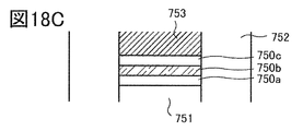
本発明の一態様の正極活物質904の充放電前後の結晶構造を、図14に示す。正極活物質904はリチウムと、遷移金属としてコバルトと、酸素と、を有する複合酸化物である。上記に加えて添加元素としてマグネシウムを有することが好ましい。また添加元素としてフッ素、塩素等のハロゲンを有することが好ましい。
FIG. 14 shows the crystal structure of the positive electrode active material 904 of one aspect of the present invention before and after charging and discharging. The positive electrode active material 904 is a composite oxide having lithium, cobalt as a transition metal, and oxygen. In addition to the above, it is preferable to have magnesium as an additive element. Further, it is preferable to have a halogen such as fluorine or chlorine as an additive element.
図14の充電深度0(放電状態)の結晶構造は、図15と同じR−3m(O3)である。一方、正極活物質904は、十分に充電された充電深度の場合、H1−3型結晶構造とは異なる構造の結晶を有する。本構造は、空間群R−3mであり、スピネル型結晶構造ではないものの、コバルト、マグネシウム等のイオンが酸素6配位位置を占め、陽イオンの配列がスピネル型と似た対称性を有する。また本構造のCoO2層の対称性はO3型と同じである。よって、本構造を本明細書等では、O3’型結晶構造、または擬スピネル型の結晶構造と呼称する。したがって、O3’型結晶構造を、擬スピネル型の結晶構造と言い換えてもよい。なお、図14に示されているO3’型結晶構造の図では、コバルト原子の対称性と酸素原子の対称性について説明するために、リチウムの表示を省略しているが、実際はCoO2層の間にコバルトに対して例えば20原子%以下のリチウムが存在する。また、O3型結晶構造及びO3’型結晶構造のいずれの場合も、CoO2層の間、つまりリチウムサイトに、希薄にマグネシウムが存在することが好ましい。また、酸素サイトに、ランダムかつ希薄に、フッ素等のハロゲンが存在することが好ましい。
The crystal structure at a charge depth of 0 (discharged state) in FIG. 14 is R-3 m (O3), which is the same as in FIG. On the other hand, the positive electrode active material 904 has a crystal having a structure different from that of the H1-3 type crystal structure when the charging depth is sufficiently charged. Although this structure is a space group R-3m and is not a spinel-type crystal structure, ions such as cobalt and magnesium occupy the oxygen 6-coordination position, and the cation arrangement has symmetry similar to that of the spinel-type. The symmetry of CoO 2 layers of this structure is the same as type O3. Therefore, this structure is referred to as an O3'type crystal structure or a pseudo-spinel type crystal structure in the present specification and the like. Therefore, the O3'type crystal structure may be paraphrased as a pseudo-spinel type crystal structure. In the figure of the O3'type crystal structure shown in FIG. 14, the display of lithium is omitted in order to explain the symmetry of the cobalt atom and the symmetry of the oxygen atom, but in reality, the CoO 2 layer In between, for example, lithium of 20 atomic% or less is present with respect to cobalt. Further, in both the O3 type crystal structure and the O3'type crystal structure, it is preferable that magnesium is dilutely present between the CoO 2 layers, that is, in the lithium site. Further, it is preferable that halogen such as fluorine is randomly and dilutely present at the oxygen site.
なお、O3’型結晶構造は、リチウムなどの軽元素は酸素4配位位置を占める場合があり、この場合もイオンの配列がスピネル型と似た対称性を有する。
In the O3'type crystal structure, light elements such as lithium may occupy the oxygen 4-coordination position, and in this case as well, the ion arrangement has symmetry similar to that of the spinel type.
また、O3’型結晶構造は、層間にランダムにLiを有するもののCdCl2型の結晶構造に類似する結晶構造であるということもできる。このCdCl2型に類似した結晶構造は、ニッケル酸リチウムを充電深度0.94まで充電したとき(Li0.06NiO2)の結晶構造と近いが、純粋なコバルト酸リチウム、またはコバルトを多く含む層状岩塩型の正極活物質では通常この結晶構造を取らないことが知られている。
It can also be said that the O3'type crystal structure is a crystal structure similar to the CdCl 2 type crystal structure, although Li is randomly provided between the layers. This crystal structure similar to CdCl type 2 is similar to the crystal structure when lithium nickel oxide is charged to a charging depth of 0.94 (Li 0.06 NiO 2 ), but contains a large amount of pure lithium cobalt oxide or cobalt. It is known that the layered rock salt type positive electrode active material usually does not have this crystal structure.
本発明の一態様の正極活物質904では、高電圧で充電し多くのリチウムが離脱したときの、結晶構造の変化が、従来の正極活物質よりも抑制されている。例えば、図14中に点線で示すように、これらの結晶構造ではCoO2層のずれがほとんどない。
In the positive electrode active material 904 of one aspect of the present invention, the change in the crystal structure when a large amount of lithium is released by charging at a high voltage is suppressed as compared with the conventional positive electrode active material. For example, as indicated by a dotted line in FIG. 14, there is little deviation of CoO 2 layers in these crystal structures.
より詳細に説明すれば、本発明の一態様の正極活物質904は、充電電圧が高い場合にも構造の安定性が高い。例えば従来の正極活物質において、リチウム金属の電位を基準として4.6V程度の充電電圧ではH1−3型結晶構造となってしまうが、本発明の一態様の正極活物質904は、当該4.6V程度の充電電圧においても、R−3m(O3)の結晶構造を保持できる。さらに高い充電電圧、例えばリチウム金属の電位を基準として4.65V乃至4.7V程度の電圧においても、本発明の一態様の正極活物質904はO3’型結晶構造を取り得る。さらに充電電圧を4.7Vより高めると、本発明の一態様の正極活物質904はようやくH1−3型結晶が観測される場合がある。また、充電電圧がより低い場合(たとえば充電電圧がリチウム金属の電位を基準として4.5V以上4.6V未満でも、本発明の一態様の正極活物質904はO3’型結晶構造を取り得る場合が有る。
More specifically, the positive electrode active material 904 of one aspect of the present invention has high structural stability even when the charging voltage is high. For example, in the conventional positive electrode active material, an H1-3 type crystal structure is formed at a charging voltage of about 4.6 V based on the potential of the lithium metal, but the positive electrode active material 904 of one aspect of the present invention has the above 4. The crystal structure of R-3m (O3) can be maintained even at a charging voltage of about 6V. Even at a higher charging voltage, for example, a voltage of about 4.65 V to 4.7 V with reference to the potential of the lithium metal, the positive electrode active material 904 of one aspect of the present invention can have an O3'type crystal structure. When the charging voltage is further increased to 4.7 V or higher, H1-3 type crystals may finally be observed in the positive electrode active material 904 of one aspect of the present invention. Further, when the charging voltage is lower (for example, even if the charging voltage is 4.5 V or more and less than 4.6 V with respect to the potential of the lithium metal, the positive electrode active material 904 of one aspect of the present invention can have an O3'type crystal structure. There is.
なお、二次電池において例えば負極活物質として黒鉛を用いる場合には、上記よりも黒鉛の電位の分だけ二次電池の電圧が低下する。黒鉛の電位はリチウム金属の電位を基準として0.05V乃至0.2V程度である。そのため例えば負極活物質に黒鉛を用いた二次電池の電圧が4.3V以上4.5V以下においても本発明の一態様の正極活物質904はR−3m(O3)の結晶構造を保持でき、さらに充電電圧を高めた領域、例えば二次電池の電圧が4.5Vを超えて4.6V以下においてもO3’型結晶構造を取り得る。さらには、充電電圧がより低い場合、例えば二次電池の電圧が4.2V以上4.3V未満でも、本発明の一態様の正極活物質904はO3’型結晶構造を取り得る場合が有る。
When graphite is used as the negative electrode active material in the secondary battery, for example, the voltage of the secondary battery is lower than the above by the potential of graphite. The potential of graphite is about 0.05V to 0.2V with respect to the potential of lithium metal. Therefore, for example, even when the voltage of the secondary battery using graphite as the negative electrode active material is 4.3 V or more and 4.5 V or less, the positive electrode active material 904 of one aspect of the present invention can maintain the crystal structure of R-3m (O3). The O3'type crystal structure can be obtained even in a region where the charging voltage is further increased, for example, when the voltage of the secondary battery exceeds 4.5 V and is 4.6 V or less. Further, when the charging voltage is lower, for example, even if the voltage of the secondary battery is 4.2 V or more and less than 4.3 V, the positive electrode active material 904 of one aspect of the present invention may have an O3'type crystal structure.
そのため、本発明の一態様の正極活物質904においては、高電圧で充放電を繰り返しても結晶構造が崩れにくい。
Therefore, in the positive electrode active material 904 of one aspect of the present invention, the crystal structure does not easily collapse even if charging and discharging are repeated at a high voltage.
また正極活物質904では、充電深度0のO3型結晶構造と、充電深度0.88のO3’型結晶構造のユニットセルあたりの体積の差は2.5%以下、より詳細には2.2%以下である。
In the positive electrode active material 904, the difference in volume per unit cell between the O3 type crystal structure having a charging depth of 0 and the O3'type crystal structure having a charging depth of 0.88 is 2.5% or less, more specifically 2.2. % Or less.
なおO3’型結晶構造は、ユニットセルにおけるコバルトと酸素の座標を、Co(0,0,0.5)、O(0,0,x)、0.20≦x≦0.25の範囲内で示すことができる。
In the O3'type crystal structure, the coordinates of cobalt and oxygen in the unit cell are within the range of Co (0,0,0.5), O (0,0,x), 0.20 ≦ x ≦ 0.25. Can be indicated by.
CoO2層間、つまりリチウムサイトにランダムかつ希薄に存在する添加元素、例えばマグネシウムは、CoO2層のずれを抑制する効果がある。そのためCoO2層間にマグネシウムが存在すると、O3’型結晶構造になりやすい。そのためマグネシウムは本発明の一態様の正極活物質904の粒子全体に分布していることが好ましい。またマグネシウムを粒子全体に分布させるために、本発明の一態様の正極活物質904の作製工程において、加熱処理を行うことが好ましい。
Additive elements such as magnesium, which are randomly and dilutely present between the two CoO layers, that is, at the lithium site, have an effect of suppressing the displacement of the two CoO layers. Therefore , if magnesium is present between the two layers of CoO, it tends to have an O3'type crystal structure. Therefore, magnesium is preferably distributed over the entire particles of the positive electrode active material 904 of one aspect of the present invention. Further, in order to distribute magnesium throughout the particles, it is preferable to perform heat treatment in the step of producing the positive electrode active material 904 according to one aspect of the present invention.
しかしながら、加熱処理の温度が高すぎると、カチオンミキシングが生じて添加元素、例えばマグネシウムがコバルトサイトに入る可能性が高まる。コバルトサイトに存在するマグネシウムは、高電圧充電時において、R−3mの構造を保つ効果がない。さらに、加熱処理の温度が高すぎると、コバルトが還元されて2価になってしまう、リチウムが蒸散するなどの悪影響も懸念される。
However, if the heat treatment temperature is too high, cationic mixing will occur and the possibility that additive elements such as magnesium will enter the cobalt site will increase. Magnesium present in cobalt sites does not have the effect of maintaining the structure of R-3m during high voltage charging. Further, if the temperature of the heat treatment is too high, there is a concern that cobalt will be reduced to divalent, and lithium will evaporate.
そこで、マグネシウムを粒子全体に分布させるための加熱処理よりも前に、コバルト酸リチウムにフッ素化合物等のハロゲン化合物を加えておくことが好ましい。ハロゲン化合物を加えることでコバルト酸リチウムの融点降下が起こる。融点降下させることで、カチオンミキシングが生じにくい温度で、マグネシウムを粒子全体に分布させることが容易となる。さらにフッ素化合物が存在すれば、電解液が分解して生じたフッ酸に対する耐食性が向上することが期待できる。
Therefore, it is preferable to add a halogen compound such as a fluorine compound to lithium cobalt oxide before the heat treatment for distributing magnesium throughout the particles. The addition of a halogen compound causes the melting point depression of lithium cobalt oxide. By lowering the melting point, it becomes easy to distribute magnesium throughout the particles at a temperature at which cationic mixing is unlikely to occur. Further, if a fluorine compound is present, it can be expected that the corrosion resistance to hydrofluoric acid generated by the decomposition of the electrolytic solution is improved.
なお、マグネシウム濃度を所望の値以上に高くすると、結晶構造の安定化への効果が小さくなってしまう場合がある。マグネシウムが、リチウムサイトに加えて、コバルトサイトにも入るようになるためと考えられる。本発明の一態様の正極活物質が有するマグネシウムの原子数は、遷移金属の原子数の0.001倍以上0.1倍以下が好ましく、0.01倍より大きく0.04倍未満がより好ましく、0.02倍程度がさらに好ましい。ここで示すマグネシウムの濃度は例えば、ICP−MS等を用いて正極活物質の粒子全体の元素分析を行った値であってもよいし、正極活物質の作製の過程における原料の配合の値に基づいてもよい。
If the magnesium concentration is higher than the desired value, the effect on stabilizing the crystal structure may be reduced. It is thought that magnesium enters cobalt sites in addition to lithium sites. The number of atoms of magnesium contained in the positive electrode active material of one aspect of the present invention is preferably 0.001 times or more and 0.1 times or less, more preferably more than 0.01 times and less than 0.04 times the number of atoms of the transition metal. , About 0.02 times is more preferable. The magnesium concentration shown here may be, for example, a value obtained by elemental analysis of the entire particles of the positive electrode active material using ICP-MS or the like, or a value of the blending of raw materials in the process of producing the positive electrode active material. It may be based.
コバルト酸リチウムにコバルト以外の金属(添加元素)として、例えばニッケル、アルミニウム、マンガン、チタン、バナジウム及びクロムから選ばれる一以上の金属を添加してもよく、特にニッケル及びアルミニウムの一以上を添加することが好ましい。マンガン、チタン、バナジウム及びクロムは安定に4価を取りやすい場合があり、構造安定性への寄与が高い場合がある。添加元素を添加することにより本発明の一態様の正極活物質では例えば、高電圧での充電状態において結晶構造がより安定になる場合がある。ここで、本発明の一態様の正極活物質において、添加元素は、コバルト酸リチウムの結晶性を大きく変えることのない濃度で添加されることが好ましい。例えば、前述のヤーン・テラー効果等を発現しない程度の量であることが好ましい。
One or more metals selected from, for example, nickel, aluminum, manganese, titanium, vanadium and chromium may be added to lithium cobaltate as metals (additive elements) other than cobalt, and in particular, one or more of nickel and aluminum are added. Is preferable. Manganese, titanium, vanadium and chromium may be stable and easily take tetravalent, and may have a high contribution to structural stability. By adding an additive element, the crystal structure of the positive electrode active material according to one aspect of the present invention may become more stable, for example, in a state of being charged at a high voltage. Here, in the positive electrode active material of one aspect of the present invention, it is preferable that the additive element is added at a concentration that does not significantly change the crystallinity of lithium cobalt oxide. For example, the amount is preferably such that the above-mentioned Jahn-Teller effect and the like are not exhibited.
図14中の凡例に示すように、ニッケル、マンガンをはじめとする遷移金属及びアルミニウムはコバルトサイトに存在することが好ましいが、一部がリチウムサイトに存在していてもよい。またマグネシウムはリチウムサイトに存在することが好ましい。酸素は、一部がフッ素と置換されていてもよい。
As shown in the legend in FIG. 14, transition metals such as nickel and manganese and aluminum are preferably present at cobalt sites, but some may be present at lithium sites. Magnesium is preferably present at lithium sites. Oxygen may be partially replaced with fluorine.
本発明の一態様の正極活物質のマグネシウム濃度が高くなるのに伴って正極活物質の容量が減少することがある。その要因として例えば、リチウムサイトにマグネシウムが入ることにより、充放電に寄与するリチウム量が減少する可能性が考えられる。また、過剰なマグネシウムが、充放電に寄与しないマグネシウム化合物を生成する場合もある。本発明の一態様の正極活物質がマグネシウムに加えて、添加元素としてニッケルを有することにより、重量あたり及び体積あたりの容量を高めることができる場合がある。また本発明の一態様の正極活物質がマグネシウムに加えて、添加元素としてアルミニウムを有することにより、重量あたり及び体積あたりの容量を高めることができる場合がある。また本発明の一態様の正極活物質がマグネシウムに加えてニッケル及びアルミニウムを有することにより、重量あたり及び体積あたりの容量を高めることができる場合がある。
The capacity of the positive electrode active material may decrease as the magnesium concentration of the positive electrode active material according to one aspect of the present invention increases. As a factor, for example, it is considered that the amount of lithium contributing to charge / discharge may decrease due to the inclusion of magnesium in the lithium site. In addition, excess magnesium may produce magnesium compounds that do not contribute to charging and discharging. By having nickel as an additive element in addition to magnesium, the positive electrode active material of one aspect of the present invention may be able to increase the capacity per weight and per volume. Further, when the positive electrode active material of one aspect of the present invention has aluminum as an additive element in addition to magnesium, the capacity per weight and per volume may be increased. Further, when the positive electrode active material of one aspect of the present invention has nickel and aluminum in addition to magnesium, it may be possible to increase the capacity per weight and per volume.
以下に、本発明の一態様の正極活物質が有するマグネシウム等の元素の濃度を、原子数を用いて表す。
Below, the concentration of an element such as magnesium contained in the positive electrode active material of one aspect of the present invention is expressed using the number of atoms.
本発明の一態様の正極活物質が有するニッケルの原子数は、コバルトの原子数の10%以下が好ましく、7.5%以下がより好ましく、0.05%以上4%以下がさらに好ましく、0.1%以上2%以下が特に好ましい。ここで示すニッケルの濃度は例えば、ICP−MS等を用いて正極活物質の粒子全体の元素分析を行った値であってもよいし、正極活物質の作製の過程における原料の配合の値に基づいてもよい。
The number of nickel atoms contained in the positive electrode active material of one aspect of the present invention is preferably 10% or less, more preferably 7.5% or less, still more preferably 0.05% or more and 4% or less, and 0. .1% or more and 2% or less is particularly preferable. The nickel concentration shown here may be, for example, a value obtained by elemental analysis of the entire particles of the positive electrode active material using ICP-MS or the like, or a value of the blending of raw materials in the process of producing the positive electrode active material. It may be based.
高電圧で充電した状態を長時間保持すると、正極活物質から遷移金属が電解液に溶出し、結晶構造が崩れる恐れが生じる。しかし上記の割合でニッケルを有することで、正極活物質904からの遷移金属の溶出を抑制できる場合がある。
If the state of being charged at a high voltage is maintained for a long time, the transition metal may be eluted from the positive electrode active material into the electrolytic solution, and the crystal structure may be destroyed. However, by having nickel in the above ratio, elution of the transition metal from the positive electrode active material 904 may be suppressed.
本発明の一態様の正極活物質が有するアルミニウムの原子数は、コバルトの原子数の0.05%以上4%以下が好ましく、0.1%以上2%以下がより好ましい。ここで示すアルミニウムの濃度は例えば、ICP−MS等を用いて正極活物質の粒子全体の元素分析を行った値であってもよいし、正極活物質の作製の過程における原料の配合の値に基づいてもよい。
The number of aluminum atoms contained in the positive electrode active material of one aspect of the present invention is preferably 0.05% or more and 4% or less, and more preferably 0.1% or more and 2% or less of the atomic number of cobalt. The concentration of aluminum shown here may be, for example, a value obtained by elemental analysis of the entire particles of the positive electrode active material using ICP-MS or the like, or a value of the blending of raw materials in the process of producing the positive electrode active material. It may be based.
本発明の一態様の正極活物質は、添加元素Xを有することが好ましく、添加元素Xとしてリンを用いることが好ましい。また、本発明の一態様の正極活物質は、リンと酸素を含む化合物を有することがより好ましい。
The positive electrode active material of one aspect of the present invention preferably has an additive element X, and it is preferable to use phosphorus as the additive element X. Moreover, it is more preferable that the positive electrode active material of one aspect of the present invention has a compound containing phosphorus and oxygen.
本発明の一態様の正極活物質が添加元素Xを含む化合物を有することにより、高電圧の充電状態を保持した場合において、ショートが生じづらい場合がある。
Since the positive electrode active material of one aspect of the present invention has a compound containing the additive element X, it may be difficult for a short circuit to occur when a high voltage charging state is maintained.
本発明の一態様の正極活物質が添加元素Xとしてリンを有する場合には、電解液の分解により発生したフッ化水素とリンが反応し、電解液中のフッ化水素濃度が低下する可能性がある。
When the positive electrode active material of one aspect of the present invention has phosphorus as the additive element X, hydrogen fluoride generated by decomposition of the electrolytic solution may react with phosphorus to reduce the hydrogen fluoride concentration in the electrolytic solution. There is.
電解液がLiPF6を有する場合、加水分解により、フッ化水素が発生する場合がある。また、正極の構成要素として用いられるPVDFとアルカリとの反応によりフッ化水素が発生する場合もある。電解液中のフッ化水素濃度が低下することにより、集電体の腐食、及び/または被膜はがれを抑制できる場合がある。また、PVDFのゲル化、及び/または不溶化による接着性の低下を抑制できる場合がある。
When the electrolytic solution has LiPF 6 , hydrogen fluoride may be generated by hydrolysis. Further, hydrogen fluoride may be generated by the reaction between PVDF used as a component of the positive electrode and an alkali. By reducing the hydrogen fluoride concentration in the electrolytic solution, corrosion of the current collector and / or peeling of the coating film may be suppressed. In addition, it may be possible to suppress a decrease in adhesiveness due to gelation and / or insolubilization of PVDF.
本発明の一態様の正極活物質が添加元素Xに加えてマグネシウムを有する場合、高電圧の充電状態における安定性が極めて高い。添加元素Xがリンである場合、リンの原子数は、コバルトの原子数の1%以上20%以下が好ましく、2%以上10%以下がより好ましく、3%以上8%以下がさらに好ましく、加えてマグネシウムの原子数は、コバルトの原子数の0.1%以上10%以下が好ましく、0.5%以上5%以下がより好ましく、0.7%以上4%以下がより好ましい。ここで示すリン及びマグネシウムの濃度は例えば、ICP−MS等を用いて正極活物質の粒子全体の元素分析を行った値であってもよいし、正極活物質の作製の過程における原料の配合の値に基づいてもよい。
When the positive electrode active material of one aspect of the present invention has magnesium in addition to the additive element X, the stability in a high voltage charging state is extremely high. When the additive element X is phosphorus, the number of atoms of phosphorus is preferably 1% or more and 20% or less, more preferably 2% or more and 10% or less, and further preferably 3% or more and 8% or less, in addition. The atomic number of magnesium is preferably 0.1% or more and 10% or less, more preferably 0.5% or more and 5% or less, and more preferably 0.7% or more and 4% or less of the atomic number of cobalt. The concentrations of phosphorus and magnesium shown here may be values obtained by elemental analysis of the entire particles of the positive electrode active material using, for example, ICP-MS or the like, or the blending of the raw materials in the process of producing the positive electrode active material. It may be based on a value.
正極活物質がクラックを有する場合、その内部にリン、より具体的には例えばリンと酸素を含む化合物が存在することにより、クラックの進行が抑制される場合がある。
When the positive electrode active material has cracks, the progress of the cracks may be suppressed by the presence of phosphorus, more specifically, for example, a compound containing phosphorus and oxygen inside the cracks.
なお図14において矢印で示した酸素原子から明らかなように、O3型結晶構造とO3’型結晶構造では酸素原子の対称性がわずかに異なる。具体的にはO3型結晶構造では酸素原子が点線で示す(−1 0 2)面に沿って整列しているのに対して、O3’型結晶構造の酸素原子は(−1 0 2)面に厳密には整列しない。これはO3’型結晶構造ではリチウムの減少に伴い4価のコバルトが増加し、ヤーン・テラーひずみが大きくなりCoO6の8面体構造がゆがんだことによる。またリチウムの減少に伴いCoO2層の酸素同士の反発が強くなったことも影響する。
As is clear from the oxygen atom indicated by the arrow in FIG. 14, the symmetry of the oxygen atom is slightly different between the O3 type crystal structure and the O3'type crystal structure. Specifically, in the O3 type crystal structure, the oxygen atoms are aligned along the (-102) plane shown by the dotted line, whereas in the O3'type crystal structure, the oxygen atoms are in the (-102) plane. Not strictly aligned with. This is because in the O3'type crystal structure, tetravalent cobalt increases as lithium decreases, the Jahn-Teller strain increases, and the octahedral structure of CoO 6 is distorted. In addition, the repulsion between oxygen in the CoO 2 layer became stronger as the amount of lithium decreased.
マグネシウムは本発明の一態様の正極活物質904の粒子全体に分布していることが好ましいが、これに加えて表層部のマグネシウム濃度が、粒子全体の平均よりも高いことが好ましい。例えば、XPS等で測定される表層部のマグネシウム濃度が、ICP−MS等で測定される粒子全体の平均のマグネシウム濃度よりも高いことが好ましい。
Magnesium is preferably distributed over the entire particles of the positive electrode active material 904 according to one aspect of the present invention, but in addition, the magnesium concentration in the surface layer portion is preferably higher than the average of the entire particles. For example, it is preferable that the magnesium concentration of the surface layer measured by XPS or the like is higher than the average magnesium concentration of the entire particles measured by ICP-MS or the like.
また、本発明の一態様の正極活物質904がコバルト以外の元素、例えばニッケル、アルミニウム、マンガン、鉄及びクロムから選ばれる一以上の金属を有する場合において、該金属の表層部における濃度が、粒子全体の平均よりも高いことが好ましい。例えば、XPS等で測定される表層部のコバルト以外の元素の濃度が、ICP−MS等で測定される粒子全体の該元素の濃度の平均よりも高いことが好ましい。
Further, when the positive electrode active material 904 of one aspect of the present invention has one or more metals selected from elements other than cobalt, for example, nickel, aluminum, manganese, iron and chromium, the concentration of the metal in the surface layer portion is determined by the particles. It is preferably higher than the overall average. For example, it is preferable that the concentration of an element other than cobalt on the surface layer measured by XPS or the like is higher than the average concentration of the element in the entire particle measured by ICP-MS or the like.
粒子表面は、いうなれば全て結晶欠陥である上に、充電時には表面からリチウムが抜けていくので内部よりもリチウム濃度が低くなりやすい部分である。そのため、不安定になりやすく結晶構造が崩れやすい部分である。表層部のマグネシウム濃度が高ければ、結晶構造の変化をより効果的に抑制することができる。また表層部のマグネシウム濃度が高いと、電解液が分解して生じたフッ酸に対する耐食性が向上することも期待できる。
The particle surface is, so to speak, a crystal defect, and lithium is released from the surface during charging, so the lithium concentration tends to be lower than that inside. Therefore, it is a part where the crystal structure is liable to collapse because it tends to be unstable. If the magnesium concentration in the surface layer is high, changes in the crystal structure can be suppressed more effectively. Further, when the magnesium concentration in the surface layer portion is high, it can be expected that the corrosion resistance to hydrofluoric acid generated by the decomposition of the electrolytic solution is improved.
またフッ素等のハロゲンも、本発明の一態様の正極活物質904の表層部の濃度が、粒子全体の平均よりも高いことが好ましい。電解液に接する領域である表層部にハロゲンが存在することで、フッ酸に対する耐食性を効果的に向上させることができる。
Also, for halogens such as fluorine, it is preferable that the concentration of the surface layer portion of the positive electrode active material 904 of one aspect of the present invention is higher than the average of all the particles. The presence of halogen in the surface layer portion, which is a region in contact with the electrolytic solution, can effectively improve the corrosion resistance to hydrofluoric acid.
このように本発明の一態様の正極活物質904の表層部は内部よりも、添加元素、例えばマグネシウム及びフッ素の濃度が高い、内部と異なる組成であることが好ましい。またその組成として常温で安定な結晶構造をとることが好ましい。そのため、表層部は内部と異なる結晶構造を有していてもよい。例えば、本発明の一態様の正極活物質904の表層部の少なくとも一部が、岩塩型の結晶構造を有していてもよい。また表層部と内部が異なる結晶構造を有する場合、表層部と内部の結晶の配向が概略一致していることが好ましい。
As described above, the surface layer portion of the positive electrode active material 904 according to one aspect of the present invention preferably has a higher concentration of additive elements such as magnesium and fluorine than the inside, and has a composition different from that of the inside. Further, it is preferable that the composition has a stable crystal structure at room temperature. Therefore, the surface layer portion may have a crystal structure different from that of the inside. For example, at least a part of the surface layer portion of the positive electrode active material 904 according to one aspect of the present invention may have a rock salt type crystal structure. When the surface layer portion and the inside have different crystal structures, it is preferable that the orientations of the surface layer portion and the internal crystals are substantially the same.
層状岩塩型結晶、及び岩塩型結晶の陰イオンは立方最密充填構造(面心立方格子構造)をとる。O3’型結晶も、陰イオンは立方最密充填構造をとると推定される。これらが接するとき、陰イオンにより構成される立方最密充填構造の向きが揃う結晶面が存在する。ただし、層状岩塩型結晶及びO3’型結晶の空間群はR−3mであり、岩塩型結晶の空間群Fm−3m(一般的な岩塩型結晶の空間群)及びFd−3m(最も単純な対称性を有する岩塩型結晶の空間群)とは異なるため、上記の条件を満たす結晶面のミラー指数は層状岩塩型結晶及びO3’型結晶と、岩塩型結晶では異なる。本明細書では、層状岩塩型結晶、O3’型結晶、及び岩塩型結晶において、陰イオンにより構成される立方最密充填構造の向きが揃うとき、結晶の配向が概略一致する、と言う場合がある。
Layered rock salt crystals and anions of rock salt crystals have a cubic closest packed structure (face-centered cubic lattice structure). It is presumed that the anion also has a cubic closest packed structure in the O3'type crystal. When they come into contact, there is a crystal plane in which the cubic close-packed structure composed of anions is oriented in the same direction. However, the space group of layered rock salt type crystals and O3'type crystals is R-3m, and the space group of rock salt type crystals Fm-3m (space group of general rock salt type crystals) and Fd-3m (the simplest symmetry). Since it is different from the space group of rock salt type crystals having properties), the mirror index of the crystal plane satisfying the above conditions is different between the layered rock salt type crystal and the O3'type crystal and the rock salt type crystal. In the present specification, it may be said that in layered rock salt type crystals, O3'type crystals, and rock salt type crystals, the orientations of the crystals are substantially the same when the orientations of the cubic closest packed structures composed of anions are aligned. is there.
二つの領域の結晶の配向が概略一致することは、TEM(透過電子顕微鏡)像、STEM(走査透過電子顕微鏡)像、HAADF−STEM(高角散乱環状暗視野走査透過電子顕微鏡)像、ABF−STEM(環状明視野走査透過電子顕微鏡)像等から判断することができる。X線回折(XRD)、電子線回折、中性子線回折等も判断の材料にすることができる。結晶の配向が概略一致していると、TEM像等で、直線状に陽イオンと陰イオンが交互に配列した列の方向の差が5度以下、より好ましくは2.5度以下である様子が観察できる。なお、TEM像等では酸素、フッ素をはじめとする軽元素は明確に観察できない場合があるが、その場合は金属元素の配列で配向の一致を判断することができる。
The fact that the orientations of the crystals in the two regions are roughly the same means that the TEM (transmission electron microscope) image, STEM (scanning transmission electron microscope) image, HAADF-STEM (high-angle scattering annular dark-field scanning transmission electron microscope) image, and ABF-STEM. (Circular bright-field scanning transmission electron microscope) It can be judged from an image or the like. X-ray diffraction (XRD), electron diffraction, neutron diffraction and the like can also be used as judgment materials. When the crystal orientations are roughly the same, the difference in the direction of the rows in which the cations and anions are arranged alternately in a straight line is 5 degrees or less, more preferably 2.5 degrees or less in the TEM image or the like. Can be observed. In some cases, light elements such as oxygen and fluorine cannot be clearly observed in the TEM image or the like, but in that case, the alignment of the metal elements can be used to determine the alignment.
ただし表層部がMgOのみ、またはMgOとCoO(II)が固溶した構造のみでは、リチウムの挿入脱離が難しくなってしまう。そのため表層部は少なくともコバルトを有し、放電状態においてはリチウムも有し、リチウムの挿入脱離の経路を有している必要がある。また、マグネシウムよりもコバルトの濃度が高いことが好ましい。
However, if the surface layer is only MgO or the structure is a solid solution of MgO and CoO (II), it will be difficult to insert and remove lithium. Therefore, the surface layer portion must have at least cobalt, also lithium in the discharged state, and have a path for inserting and removing lithium. Further, it is preferable that the concentration of cobalt is higher than that of magnesium.
また、添加元素Xは本発明の一態様の正極活物質904の粒子の表層部に位置することが好ましい。例えば本発明の一態様の正極活物質904は、添加元素Xを有する被膜に覆われていてもよい。
Further, the additive element X is preferably located on the surface layer portion of the particles of the positive electrode active material 904 of one aspect of the present invention. For example, the positive electrode active material 904 of one aspect of the present invention may be covered with a film having an additive element X.
≪粒界≫
本発明の一態様の正極活物質904が有する添加元素Xは、内部にランダムかつ希薄に存在していてもよいが、一部は粒界に偏析していることがより好ましい。
≪Grain boundary≫
The additive element X contained in the positive electrode active material 904 of one aspect of the present invention may be randomly and dilutely present inside, but it is more preferable that a part of the additive element X is segregated at the grain boundaries.
換言すれば、本発明の一態様の正極活物質904の粒界及びその近傍の添加元素Xの濃度も、内部の他の領域よりも高いことが好ましい。
In other words, it is preferable that the concentration of the additive element X at the grain boundary of the positive electrode active material 904 of one aspect of the present invention and its vicinity is also higher than that of other regions inside.
粒子表面と同様、粒界も面欠陥である。そのため不安定になりやすく結晶構造の変化が始まりやすい。そのため、粒界及びその近傍の添加元素Xの濃度が高ければ、結晶構造の変化をより効果的に抑制することができる。
Similar to the particle surface, the grain boundaries are also surface defects. Therefore, it tends to be unstable and the crystal structure tends to change. Therefore, if the concentration of the additive element X in and near the grain boundary is high, the change in the crystal structure can be suppressed more effectively.
また、粒界及びその近傍の添加元素Xの濃度が高い場合、本発明の一態様の正極活物質904の粒子の粒界に沿ってクラックが生じた場合でも、クラックにより生じた表面の近傍で添加元素Xの濃度が高くなる。そのためクラックが生じた後の正極活物質においてもフッ酸に対する耐食性を高めることができる。
Further, when the concentration of the additive element X in the grain boundary and its vicinity is high, even if a crack occurs along the grain boundary of the particles of the positive electrode active material 904 according to the present invention, in the vicinity of the surface generated by the crack. The concentration of the additive element X increases. Therefore, the corrosion resistance to hydrofluoric acid can be enhanced even in the positive electrode active material after cracks have occurred.
なお本明細書等において、粒界の近傍とは、粒界から10nm程度までの領域をいうこととする。
In the present specification and the like, the vicinity of the grain boundary means a region from the grain boundary to about 10 nm.
<粒径>
本発明の一態様の正極活物質904の粒径は、大きすぎるとリチウムの拡散が難しくなる、集電体に塗工したときに活物質層の表面が粗くなりすぎる、等の問題がある。一方、小さすぎると、集電体への塗工時に活物質層を担持しにくくなる、電解液との反応が過剰に進む等の問題点も生じる。そのため、平均粒子径(D50:メディアン径ともいう。)が、1μm以上100μm以下が好ましく、2μm以上40μm以下であることがより好ましく、5μm以上30μm以下がさらに好ましい。
<Diameter>
If the particle size of the positive electrode active material 904 of one aspect of the present invention is too large, there are problems such as difficulty in diffusing lithium and the surface of the active material layer becoming too rough when applied to a current collector. On the other hand, if it is too small, problems such as difficulty in supporting the active material layer at the time of coating on the current collector and excessive reaction with the electrolytic solution occur. Therefore, the average particle size (D50: also referred to as median diameter) is preferably 1 μm or more and 100 μm or less, more preferably 2 μm or more and 40 μm or less, and further preferably 5 μm or more and 30 μm or less.
<分析方法>
ある正極活物質が、高電圧で充電されたときO3’型結晶構造を示す否かは、高電圧で充電された正極を、XRD、電子線回折、中性子線回折、電子スピン共鳴(ESR)、核磁気共鳴(NMR)等を用いて解析することで判断できる。特にXRDは、正極活物質が有するコバルト等の遷移金属の対称性を高分解能で解析できる、結晶性の高さおよび結晶の配向性を比較できる、格子の周期性歪みおよび結晶子サイズの解析ができる、二次電池を解体して得た正極をそのまま測定しても十分な精度を得られる、等の点で好ましい。
<Analysis method>
Whether or not a positive electrode active material exhibits an O3'-type crystal structure when charged at a high voltage is determined by XRD, electron diffraction, neutron diffraction, electron spin resonance (ESR), and electron spin resonance (ESR). It can be judged by analysis using nuclear magnetic resonance (NMR) or the like. In particular, XRD can analyze the symmetry of transition metals such as cobalt contained in the positive electrode active material with high resolution, compare the height of crystallinity and the orientation of crystals, and analyze the periodic strain and crystallite size of the lattice. It is preferable in that it is possible to obtain sufficient accuracy even if the positive electrode obtained by disassembling the secondary battery is measured as it is.
本発明の一態様の正極活物質904は、これまで述べたように高電圧で充電した状態と放電状態とで結晶構造の変化が少ないことが特徴である。高電圧で充電した状態で、放電状態との変化が大きな結晶構造が50wt%以上を占める材料は、高電圧の充放電に耐えられないため好ましくない。そして添加元素を添加するだけでは目的の結晶構造をとらない場合があることに注意が必要である。例えばマグネシウム及びフッ素を有するコバルト酸リチウム、という点で共通していても、高電圧で充電した状態でO3’型結晶構造が60wt%以上になる場合と、H1−3型結晶構造が50wt%以上を占める場合と、がある。また、所定の電圧では、O3’型結晶構造がほぼ100wt%になり、さらに当該所定の電圧をあげるとH1−3型結晶構造が生じる場合もある。そのため、本発明の一態様の正極活物質904であるか否かを判断するには、XRDをはじめとする結晶構造についての解析が必要である。
As described above, the positive electrode active material 904 according to one aspect of the present invention is characterized in that the crystal structure does not change much between the state of being charged at a high voltage and the state of being discharged. A material in which a crystal structure occupying 50 wt% or more in a state of being charged with a high voltage and having a large change from the state of being discharged is not preferable because it cannot withstand the charging and discharging of a high voltage. It should be noted that the desired crystal structure may not be obtained simply by adding the additive element. For example, even if lithium cobalt oxide having magnesium and fluorine is common, the O3'type crystal structure becomes 60 wt% or more when charged at a high voltage, and the H1-3 type crystal structure becomes 50 wt% or more. There are cases where it occupies. Further, at a predetermined voltage, the O3'type crystal structure becomes approximately 100 wt%, and when the predetermined voltage is further increased, an H1-3 type crystal structure may occur. Therefore, in order to determine whether or not the cathode active material 904 is one aspect of the present invention, it is necessary to analyze the crystal structure including XRD.
ただし、高電圧で充電した状態または放電状態の正極活物質は、大気に触れると結晶構造の変化を起こす場合がある。例えばO3’型結晶構造からH1−3型結晶構造に変化する場合がある。そのため、サンプルはすべてアルゴン雰囲気等の不活性雰囲気でハンドリングすることが好ましい。
However, the positive electrode active material in the state of being charged or discharged at a high voltage may change its crystal structure when it comes into contact with the atmosphere. For example, the O3'type crystal structure may change to the H1-3 type crystal structure. Therefore, it is preferable to handle all the samples in an inert atmosphere such as an argon atmosphere.
(実施の形態4)
本実施の形態では、図16乃至図19用いて本発明の一態様の二次電池の例について説明する。
(Embodiment 4)
In the present embodiment, an example of the secondary battery of one aspect of the present invention will be described with reference to FIGS. 16 to 19.
<二次電池の構成例1>
以下に、正極、負極および電解液が、外装体に包まれている二次電池を例にとって説明する。
<Configuration example 1 of secondary battery>
Hereinafter, a secondary battery in which the positive electrode, the negative electrode, and the electrolytic solution are wrapped in an exterior body will be described as an example.
〔正極〕
正極は、正極活物質層および正極集電体を有する。正極活物質層は正極活物質を有し、導電材およびバインダを有していてもよい。正極活物質には、先の実施の形態で説明した作製方法を用いて作製した正極活物質を用いる。以下に一例として、活物質層200に導電材としてグラフェン化合物を用いる場合の断面構成例を説明する。
[Positive electrode]
The positive electrode has a positive electrode active material layer and a positive electrode current collector. The positive electrode active material layer has a positive electrode active material, and may have a conductive material and a binder. As the positive electrode active material, a positive electrode active material prepared by using the manufacturing method described in the previous embodiment is used. Hereinafter, as an example, a cross-sectional configuration example in the case where a graphene compound is used as the conductive material in the active material layer 200 will be described.
図16Aに、活物質層200の縦断面図を示す。活物質層200は、粒状の正極活物質101と、導電材としてのグラフェン化合物201と、バインダ(図示せず)と、を含む。
FIG. 16A shows a vertical cross-sectional view of the active material layer 200. The active material layer 200 includes a granular positive electrode active material 101, a graphene compound 201 as a conductive material, and a binder (not shown).
本明細書等においてグラフェン化合物201とは、グラフェン、多層グラフェン、マルチグラフェン、酸化グラフェン(GO)、多層酸化グラフェン、マルチ酸化グラフェン、還元された酸化グラフェン(RGO)、還元された多層酸化グラフェン、還元されたマルチ酸化グラフェン、グラフェン量子ドット等を含む。グラフェン化合物とは、炭素を有し、平板状、シート状等の形状を有し、炭素6員環で形成された二次元的構造を有するものをいう。該炭素6員環で形成された二次元的構造は炭素シートといってもよい。グラフェン化合物は官能基を有してもよい。またグラフェン化合物は屈曲した形状を有することが好ましい。またグラフェン化合物は丸まってカーボンナノファイバーのようになっていてもよい。グラフェン化合物は、高い導電性を有するという優れた電気特性と、高い柔軟性および高い機械的強度を有するという優れた物理特性と、を有する場合がある。
In the present specification and the like, the graphene compound 201 refers to graphene, multi-layer graphene, multi-graphene, graphene oxide (GO), multi-layer graphene oxide, multi-graphene oxide, reduced graphene oxide (RGO), reduced multi-layer graphene oxide, reduction. Includes graphene multi-oxide, graphene quantum dots, etc. The graphene compound has carbon, has a flat plate shape, a sheet shape, or the like, and has a two-dimensional structure formed by a carbon 6-membered ring. The two-dimensional structure formed by the carbon 6-membered ring may be called a carbon sheet. The graphene compound may have a functional group. Further, the graphene compound preferably has a bent shape. The graphene compound may also be curled up into carbon nanofibers. Graphene compounds may have excellent electrical properties such as high conductivity and excellent physical properties such as high flexibility and high mechanical strength.
本明細書等において酸化グラフェンとは、炭素と、酸素を有し、シート状の形状を有し、官能基、特にエポキシ基、カルボキシ基またはヒドロキシ基を有するものをいう。
In the present specification and the like, graphene oxide refers to a graphene oxide having carbon and oxygen, having a sheet-like shape, and having a functional group, particularly an epoxy group, a carboxy group or a hydroxy group.
本明細書等において還元された酸化グラフェンとは、炭素と、酸素を有し、シート状の形状を有し、炭素6員環で形成された二次元的構造を有するものをいう。炭素シートといってもよい。還元された酸化グラフェンは1枚でも機能するが、複数枚が積層されていてもよい。還元された酸化グラフェンは、炭素の濃度が80atomic%より大きく、酸素の濃度が2atomic%以上15atomic%以下である部分を有することが好ましい。このような炭素濃度および酸素濃度とすることで、少量でも導電性の高い導電材として機能することができる。また還元された酸化グラフェンは、ラマンスペクトルにおけるGバンドとDバンドの強度比G/Dが1以上であることが好ましい。このような強度比である還元された酸化グラフェンは、少量でも導電性の高い導電材として機能することができる。
In the present specification and the like, reduced graphene oxide refers to graphene oxide having carbon and oxygen, having a sheet-like shape, and having a two-dimensional structure formed by a carbon 6-membered ring. It may be called a carbon sheet. Although one reduced graphene oxide functions, a plurality of reduced graphene oxides may be laminated. The reduced graphene oxide preferably has a portion having a carbon concentration of more than 80 atomic% and an oxygen concentration of 2 atomic% or more and 15 atomic% or less. By setting such carbon concentration and oxygen concentration, it is possible to function as a highly conductive conductive material even in a small amount. Further, the reduced graphene oxide preferably has an intensity ratio G / D of G band and D band of 1 or more in the Raman spectrum. The reduced graphene oxide having such a strength ratio can function as a highly conductive conductive material even in a small amount.
活物質層200の縦断面においては、図16Bに示すように、活物質層200の内部において概略均一にシート状のグラフェン化合物201が分散する。図16Bにおいてはグラフェン化合物201を模式的に太線で表しているが、実際には炭素分子の単層又は多層の厚みを有する薄膜である。複数のグラフェン化合物201は、複数の粒状の正極活物質101を一部覆うように、あるいは複数の粒状の正極活物質101の表面上に張り付くように形成されているため、互いに面接触している。そのため、活物質と導電材との接触面積を増大させることができる。
In the vertical cross section of the active material layer 200, as shown in FIG. 16B, the sheet-shaped graphene compound 201 is dispersed substantially uniformly inside the active material layer 200. Although the graphene compound 201 is schematically represented by a thick line in FIG. 16B, it is actually a thin film having a thickness of a single layer or multiple layers of carbon molecules. Since the plurality of graphene compounds 201 are formed so as to partially cover the plurality of granular positive electrode active materials 101 or to stick to the surface of the plurality of granular positive electrode active materials 101, they are in surface contact with each other. .. Therefore, the contact area between the active material and the conductive material can be increased.
ここで、複数のグラフェン化合物同士が結合することにより、網目状のグラフェン化合物シート(以下グラフェン化合物ネットまたはグラフェンネットと呼ぶ)を形成することができる。活物質をグラフェンネットが被覆する場合に、グラフェンネットは活物質同士を結合するバインダとしても機能することができる。よって、バインダの量を少なくすることができる、又は使用しないことができるため、電極体積または電極重量に占める活物質の比率を向上させることができる。すなわち、二次電池の容量を増加させることができる。
Here, a network-like graphene compound sheet (hereinafter referred to as graphene compound net or graphene net) can be formed by binding a plurality of graphene compounds to each other. When the active material is covered with graphene net, the graphene net can also function as a binder for binding the active materials to each other. Therefore, since the amount of the binder can be reduced or not used, the ratio of the active material to the electrode volume or the electrode weight can be improved. That is, the capacity of the secondary battery can be increased.
ここで、グラフェン化合物201として酸化グラフェンを用い、活物質と混合して活物質層200となる層を形成後、還元することが好ましい。つまり完成後の活物質層は還元された酸化グラフェンを有することが好ましい。グラフェン化合物201の形成に、極性溶媒中での分散性が極めて高い酸化グラフェンを用いることにより、グラフェン化合物201を活物質層200の内部において概略均一に分散させることができる。均一に分散した酸化グラフェンを含有する分散媒から溶媒を揮発除去し、酸化グラフェンを還元するため、活物質層200に残留するグラフェン化合物201は部分的に重なり合い、互いに面接触する程度に分散していることで三次元的な導電パスを形成することができる。なお、酸化グラフェンの還元は、例えば熱処理により行ってもよいし、還元剤を用いて行ってもよい。
Here, it is preferable to use graphene oxide as the graphene compound 201, mix it with the active material to form a layer to be the active material layer 200, and then reduce the layer. That is, it is preferable that the active material layer after completion has reduced graphene oxide. By using graphene oxide having extremely high dispersibility in a polar solvent for forming the graphene compound 201, the graphene compound 201 can be dispersed substantially uniformly inside the active material layer 200. In order to volatilize and remove the solvent from the uniformly dispersed graphene oxide-containing dispersion medium and reduce the graphene oxide, the graphene compound 201 remaining in the active material layer 200 partially overlaps and is dispersed to such an extent that it comes into surface contact with each other. By doing so, a three-dimensional conductive path can be formed. The graphene oxide may be reduced, for example, by heat treatment or by using a reducing agent.
従って、活物質と点接触するアセチレンブラック等の粒状の導電材と異なり、グラフェン化合物201は接触抵抗の低い面接触を可能とするものであるから、通常の導電材よりも少量で粒状の正極活物質101とグラフェン化合物201との電気伝導性を向上させることができる。よって、正極活物質101の活物質層200における比率を増加させることができる。これにより、二次電池の放電容量を増加させることができる。
Therefore, unlike a granular conductive material such as acetylene black that makes point contact with an active material, the graphene compound 201 enables surface contact with low contact resistance, so that the amount of granular positive electrode activity is smaller than that of a normal conductive material. The electrical conductivity between the substance 101 and the graphene compound 201 can be improved. Therefore, the ratio of the positive electrode active material 101 in the active material layer 200 can be increased. As a result, the discharge capacity of the secondary battery can be increased.
また、予め、スプレードライ装置を用いることで、活物質の表面全体を覆って導電材であるグラフェン化合物を被膜として形成し、さらに活物質同士間をグラフェン化合物で導電パスを形成することもできる。
Further, by using a spray-drying device in advance, it is possible to cover the entire surface of the active material to form a graphene compound as a conductive material as a film, and further to form a conductive path between the active materials with the graphene compound.
〔負極〕
負極は、負極活物質層および負極集電体を有する。負極活物質層は負極活物質を有し、導電材およびバインダを有していてもよい。
[Negative electrode]
The negative electrode has a negative electrode active material layer and a negative electrode current collector. The negative electrode active material layer has a negative electrode active material, and may have a conductive material and a binder.
[負極活物質]
負極活物質としては、例えば合金系材料または炭素系材料等を用いることができる。
[Negative electrode active material]
As the negative electrode active material, for example, an alloy-based material, a carbon-based material, or the like can be used.
負極活物質として、リチウムとの合金化・脱合金化反応により充放電反応を行うことが可能な元素を用いることができる。例えば、シリコン、スズ、ガリウム、アルミニウム、ゲルマニウム、鉛、アンチモン、ビスマス、銀、亜鉛、カドミウム、インジウム等のうち少なくとも一つを含む材料を用いることができる。このような元素は炭素と比べて容量が大きく、特にシリコンは理論容量が4200mAh/gと高い。このため、負極活物質にシリコンを用いることが好ましい。また、これらの元素を有する化合物を用いてもよい。例えば、SiO、Mg2Si、Mg2Ge、SnO、SnO2、Mg2Sn、SnS2、V2Sn3、FeSn2、CoSn2、Ni3Sn2、Cu6Sn5、Ag3Sn、Ag3Sb、Ni2MnSb、CeSb3、LaSn3、La3Co2Sn7、CoSb3、InSb、SbSn等がある。ここで、リチウムとの合金化・脱合金化反応により充放電反応を行うことが可能な元素、および該元素を有する化合物等を合金系材料と呼ぶ場合がある。
As the negative electrode active material, an element capable of performing a charge / discharge reaction by an alloying / dealloying reaction with lithium can be used. For example, a material containing at least one of silicon, tin, gallium, aluminum, germanium, lead, antimony, bismuth, silver, zinc, cadmium, indium and the like can be used. Such elements have a larger capacity than carbon, and silicon in particular has a high theoretical capacity of 4200 mAh / g. Therefore, it is preferable to use silicon as the negative electrode active material. Moreover, you may use the compound which has these elements. For example, SiO, Mg 2 Si, Mg 2 Ge, SnO, SnO 2 , Mg 2 Sn, SnS 2 , V 2 Sn 3 , FeSn 2 , CoSn 2 , Ni 3 Sn 2 , Cu 6 Sn 5 , Ag 3 Sn, Ag. There are 3 Sb, Ni 2 MnSb, CeSb 3 , LaSn 3 , La 3 Co 2 Sn 7 , CoSb 3 , InSb, SbSn and the like. Here, an element capable of performing a charge / discharge reaction by an alloying / dealloying reaction with lithium, a compound having the element, and the like may be referred to as an alloy-based material.
本明細書等において、SiOは例えば一酸化シリコンを指す。あるいはSiOは、SiOxと表すこともできる。ここでxは1近傍の値を有することが好ましい。例えばxは、0.2以上1.5以下が好ましく、0.3以上1.2以下がより好ましい。
In the present specification and the like, SiO refers to, for example, silicon monoxide. Alternatively, SiO can also be expressed as SiO x. Here, x preferably has a value in the vicinity of 1. For example, x is preferably 0.2 or more and 1.5 or less, and more preferably 0.3 or more and 1.2 or less.
炭素系材料としては、黒鉛、易黒鉛化性炭素(ソフトカーボン)、難黒鉛化性炭素(ハードカーボン)、カーボンナノチューブ、グラフェン、カーボンブラック等を用いればよい。
As the carbon-based material, graphite, easily graphitizable carbon (soft carbon), non-graphitizable carbon (hard carbon), carbon nanotubes, graphene, carbon black and the like may be used.
黒鉛としては、人造黒鉛、天然黒鉛等が挙げられる。人造黒鉛としては例えば、メソカーボンマイクロビーズ(MCMB)、コークス系人造黒鉛、ピッチ系人造黒鉛等が挙げられる。ここで人造黒鉛として、球状の形状を有する球状黒鉛を用いることができる。例えば、MCMBは球状の形状を有する場合があり、好ましい。また、MCMBはその表面積を小さくすることが比較的容易であり、好ましい場合がある。天然黒鉛としては例えば、鱗片状黒鉛、球状化天然黒鉛等が挙げられる。
Examples of graphite include artificial graphite and natural graphite. Examples of the artificial graphite include mesocarbon microbeads (MCMB), coke-based artificial graphite, pitch-based artificial graphite and the like. Here, as the artificial graphite, spheroidal graphite having a spherical shape can be used. For example, MCMB may have a spherical shape, which is preferable. In addition, MCMB is relatively easy to reduce its surface area and may be preferable. Examples of natural graphite include scaly graphite and spheroidized natural graphite.
黒鉛は、リチウムイオンが黒鉛に挿入されたとき(リチウム−黒鉛層間化合物の生成時)にリチウム金属と同程度に低い電位を示す(0.05V以上0.3V以下 vs.Li/Li+)。これにより、リチウムイオン二次電池は高い作動電圧を示すことができる。さらに、黒鉛は、単位体積当たりの容量が比較的高い、体積膨張が比較的小さい、安価である、リチウム金属に比べて安全性が高い等の利点を有するため、好ましい。
Graphite exhibits a potential as low as lithium metal when lithium ions are inserted into graphite (during the formation of a lithium-graphite intercalation compound) (0.05 V or more and 0.3 V or less vs. Li / Li +). As a result, the lithium ion secondary battery can exhibit a high operating voltage. Further, graphite is preferable because it has advantages such as relatively high capacity per unit volume, relatively small volume expansion, low cost, and high safety as compared with lithium metal.
また、負極活物質として、二酸化チタン(TiO2)、リチウムチタン酸化物(Li4Ti5O12)、リチウム−黒鉛層間化合物(LixC6)、五酸化ニオブ(Nb2O5)、酸化タングステン(WO2)、酸化モリブデン(MoO2)等の酸化物を用いることができる。
Further, as the negative electrode active material, titanium dioxide (TiO 2 ), lithium titanium oxide (Li 4 Ti 5 O 12 ), lithium-graphite interlayer compound (Li x C 6 ), niobium pentoxide (Nb 2 O 5 ), oxidation. Oxides such as tungsten (WO 2 ) and molybdenum oxide (MoO 2 ) can be used.
また、負極活物質として、リチウムと遷移金属の複窒化物である、Li3N型構造をもつLi3−xMxN(M=Co、Ni、Cu)を用いることができる。例えば、Li2.6Co0.4N3は大きな充放電容量(900mAh/g、1890mAh/cm3)を示し好ましい。
Further, as the negative electrode active material, Li 3-x M x N (M = Co, Ni, Cu) having a Li 3 N type structure, which is a compound nitride of lithium and a transition metal, can be used. For example, Li 2.6 Co 0.4 N 3 shows a large charge / discharge capacity (900 mAh / g, 1890 mAh / cm 3 ) and is preferable.
リチウムと遷移金属の複窒化物を用いると、負極活物質中にリチウムイオンを含むため、正極活物質としてリチウムイオンを含まないV2O5、Cr3O8等の材料と組み合わせることができ好ましい。なお、正極活物質にリチウムイオンを含む材料を用いる場合でも、あらかじめ正極活物質に含まれるリチウムイオンを脱離させることで、負極活物質としてリチウムと遷移金属の複窒化物を用いることができる。
When a double nitride of lithium and a transition metal is used, lithium ions are contained in the negative electrode active material, so that it can be combined with materials such as V 2 O 5 and Cr 3 O 8 which do not contain lithium ions as the positive electrode active material, which is preferable. .. Even when a material containing lithium ions is used as the positive electrode active material, a double nitride of lithium and a transition metal can be used as the negative electrode active material by desorbing the lithium ions contained in the positive electrode active material in advance.
また、コンバージョン反応が生じる材料を負極活物質として用いることもできる。例えば、酸化コバルト(CoO)、酸化ニッケル(NiO)、酸化鉄(FeO)等の、リチウムとの合金を作らない遷移金属酸化物を負極活物質に用いてもよい。コンバージョン反応が生じる材料としては、さらに、Fe2O3、CuO、Cu2O、RuO2、Cr2O3等の酸化物、CoS0.89、NiS、CuS等の硫化物、Zn3N2、Cu3N、Ge3N4等の窒化物、NiP2、FeP2、CoP3等のリン化物、FeF3、BiF3等のフッ化物でも起こる。
Further, a material that causes a conversion reaction can also be used as the negative electrode active material. For example, a transition metal oxide that does not form an alloy with lithium, such as cobalt oxide (CoO), nickel oxide (NiO), and iron oxide (FeO), may be used as the negative electrode active material. Materials that cause a conversion reaction include oxides such as Fe 2 O 3 , CuO, Cu 2 O, RuO 2 , Cr 2 O 3 , sulfides such as CoS 0.89 , NiS, and CuS, and Zn 3 N 2. , Cu 3 N, Ge 3 N 4 and other nitrides, NiP 2 , FeP 2 and CoP 3 and other phosphates, and FeF 3 and BiF 3 and other fluorides.
負極活物質層が有することのできる導電材およびバインダとしては、正極活物質層が有することのできる導電材およびバインダと同様の材料を用いることができる。
As the conductive material and the binder that the negative electrode active material layer can have, the same material as the conductive material and the binder that the positive electrode active material layer can have can be used.
[負極集電体]
負極集電体には、正極集電体と同様の材料を用いることができる。なお負極集電体は、リチウム等のキャリアイオンと合金化しない材料を用いることが好ましい。
[Negative electrode current collector]
The same material as the positive electrode current collector can be used for the negative electrode current collector. The negative electrode current collector preferably uses a material that does not alloy with carrier ions such as lithium.
〔電解液〕
電解液は、溶媒と電解質を有する。電解液の溶媒としては、非プロトン性有機溶媒が好ましく、例えば、エチレンカーボネート(EC)、プロピレンカーボネート(PC)、ブチレンカーボネート、クロロエチレンカーボネート、ビニレンカーボネート、γ−ブチロラクトン、γ−バレロラクトン、ジメチルカーボネート(DMC)、ジエチルカーボネート(DEC)、エチルメチルカーボネート(EMC)、ギ酸メチル、酢酸メチル、酢酸エチル、プロピオン酸メチル、プロピオン酸エチル、プロピオン酸プロピル、酪酸メチル、1,3−ジオキサン、1,4−ジオキサン、ジメトキシエタン(DME)、ジメチルスルホキシド、ジエチルエーテル、メチルジグライム、アセトニトリル、ベンゾニトリル、テトラヒドロフラン、スルホラン、スルトン等の1種、又はこれらのうちの2種以上を任意の組み合わせおよび比率で用いることができる。
[Electrolytic solution]
The electrolytic solution has a solvent and an electrolyte. The solvent of the electrolytic solution is preferably an aproton organic solvent, for example, ethylene carbonate (EC), propylene carbonate (PC), butylene carbonate, chloroethylene carbonate, vinylene carbonate, γ-butylolactone, γ-valerolactone, dimethyl carbonate. (DMC), diethyl carbonate (DEC), ethyl methyl carbonate (EMC), methyl formate, methyl acetate, ethyl acetate, methyl propionate, ethyl propionate, propyl propionate, methyl butyrate, 1,3-dioxane, 1,4 -Use one of dioxane, dimethoxyethane (DME), dimethyl sulfoxide, diethyl ether, methyl diglime, acetonitrile, benzonitrile, tetrahydrofuran, sulfolane, sulton, etc., or two or more of them in any combination and ratio. be able to.
また、電解液の溶媒として、難燃性および難揮発性であるイオン液体(常温溶融塩)を一つ又は複数用いることで、二次電池の内部短絡または過充電等によって内部温度が上昇しても、二次電池の破裂または発火などを防ぐことができる。イオン液体は、カチオンとアニオンからなり、有機カチオンとアニオンとを含む。電解液に用いる有機カチオンとして、四級アンモニウムカチオン、三級スルホニウムカチオン、および四級ホスホニウムカチオン等の脂肪族オニウムカチオン、イミダゾリウムカチオンおよびピリジニウムカチオン等の芳香族カチオンが挙げられる。また、電解液に用いるアニオンとして、1価のアミド系アニオン、1価のメチド系アニオン、フルオロスルホン酸アニオン、パーフルオロアルキルスルホン酸アニオン、テトラフルオロボレートアニオン、パーフルオロアルキルボレートアニオン、ヘキサフルオロホスフェートアニオン、またはパーフルオロアルキルホスフェートアニオン等が挙げられる。
Further, by using one or more flame-retardant and volatile ionic liquids (normal temperature molten salt) as the solvent of the electrolytic solution, the internal temperature rises due to an internal short circuit or overcharging of the secondary battery. Also, it is possible to prevent the secondary battery from exploding or catching fire. Ionic liquids consist of cations and anions, including organic cations and anions. Examples of the organic cation used in the electrolytic solution include aliphatic onium cations such as quaternary ammonium cations, tertiary sulfonium cations, and quaternary phosphonium cations, and aromatic cations such as imidazolium cations and pyridinium cations. Further, as anions used in the electrolytic solution, monovalent amide anion, monovalent methide anion, fluorosulfonic anion, perfluoroalkyl sulfonic acid anion, tetrafluoroborate anion, perfluoroalkyl borate anion, hexafluorophosphate anion. , Or perfluoroalkyl phosphate anion and the like.
また、上記の溶媒に溶解させる電解質としては、例えばLiPF6、LiClO4、LiAsF6、LiBF4、LiAlCl4、LiSCN、LiBr、LiI、Li2SO4、Li2B10Cl10、Li2B12Cl12、LiCF3SO3、LiC4F9SO3、LiC(CF3SO2)3、LiC(C2F5SO2)3、LiN(CF3SO2)2、LiN(C4F9SO2)(CF3SO2)、LiN(C2F5SO2)2等のリチウム塩を一種、又はこれらのうちの二種以上を任意の組み合わせおよび比率で用いることができる。
As the electrolytes dissolved in the above solvent, for example LiPF 6, LiClO 4, LiAsF 6 , LiBF 4, LiAlCl 4, LiSCN, LiBr, LiI, Li 2 SO 4, Li 2 B 10 Cl 10, Li 2 B 12 Cl 12 , LiCF 3 SO 3 , LiC 4 F 9 SO 3 , LiC (CF 3 SO 2 ) 3 , LiC (C 2 F 5 SO 2 ) 3 , LiN (CF 3 SO 2 ) 2 , LiN (C 4 F 9) Lithium salts such as SO 2 ) (CF 3 SO 2 ) and LiN (C 2 F 5 SO 2 ) 2 can be used alone, or two or more of them can be used in any combination and ratio.
二次電池に用いる電解液は、粒状のごみまたは電解液の構成元素以外の元素(以下、単に「不純物」ともいう。)の含有量が少ない高純度化された電解液を用いることが好ましい。具体的には、電解液に対する不純物の重量比を1%以下、好ましくは0.1%以下、より好ましくは0.01%以下とすることが好ましい。
As the electrolytic solution used for the secondary battery, it is preferable to use a highly purified electrolytic solution having a small content of elements other than granular dust or constituent elements of the electrolytic solution (hereinafter, also simply referred to as “impurities”). Specifically, the weight ratio of impurities to the electrolytic solution is preferably 1% or less, preferably 0.1% or less, and more preferably 0.01% or less.
また、電解液にビニレンカーボネート、プロパンスルトン(PS)、tert−ブチルベンゼン(TBB)、フルオロエチレンカーボネート(FEC)、リチウムビス(オキサレート)ボレート(LiBOB)、またスクシノニトリル、アジポニトリル等のジニトリル化合物などの添加剤を添加してもよい。添加する材料の濃度は、例えば溶媒全体に対して0.1wt%以上5wt%以下とすればよい。
Further, the electrolytic solution includes vinylene carbonate, propane sultone (PS), tert-butylbenzene (TBB), fluoroethylene carbonate (FEC), lithium bis (oxalate) borate (LiBOB), and dinitrile compounds such as succinonitrile and adiponitrile. Additives may be added. The concentration of the material to be added may be, for example, 0.1 wt% or more and 5 wt% or less with respect to the entire solvent.
また、ポリマーを電解液で膨潤させたポリマーゲル電解質を用いてもよい。
Alternatively, a polymer gel electrolyte obtained by swelling the polymer with an electrolytic solution may be used.
ポリマーゲル電解質を用いることで、漏液性等に対する安全性が高まる。また、二次電池の薄型化および軽量化が可能である。
By using the polymer gel electrolyte, the safety against liquid leakage and the like is enhanced. In addition, the secondary battery can be made thinner and lighter.
ゲル化されるポリマーとして、シリコーンゲル、アクリルゲル、アクリロニトリルゲル、ポリエチレンオキサイド系ゲル、ポリプロピレンオキサイド系ゲル、フッ素系ポリマーのゲル等を用いることができる。
As the gelled polymer, silicone gel, acrylic gel, acrylonitrile gel, polyethylene oxide gel, polypropylene oxide gel, fluorine polymer gel and the like can be used.
ポリマーとしては、例えばポリエチレンオキシド(PEO)などのポリアルキレンオキシド構造を有するポリマー、PVDF、ポリアクリロニトリル、およびそれらを含む共重合体等を用いることができる。例えばPVDFとヘキサフルオロプロピレン(HFP)の共重合体であるPVDF−HFPを用いることができる。また、形成されるポリマーは、多孔質形状を有してもよい。
As the polymer, for example, a polymer having a polyalkylene oxide structure such as polyethylene oxide (PEO), PVDF, polyacrylonitrile, and a copolymer containing them can be used. For example, PVDF-HFP, which is a copolymer of PVDF and hexafluoropropylene (HFP), can be used. Further, the polymer to be formed may have a porous shape.
また、電解液の代わりに、硫化物系または酸化物系等の無機物材料を有する固体電解質、もしくはPEO(ポリエチレンオキシド)系等の高分子材料を有する固体電解質を用いることができる。固体電解質を用いる場合には、セパレータおよびスペーサの設置が不要となる。また、電池全体を固体化できるため、漏液のおそれがなくなり安全性が飛躍的に向上する。
Further, instead of the electrolytic solution, a solid electrolyte having an inorganic material such as a sulfide type or an oxide type, or a solid electrolyte having a polymer material such as PEO (polyethylene oxide) type can be used. When a solid electrolyte is used, it is not necessary to install a separator and a spacer. In addition, since the entire battery can be solidified, there is no risk of liquid leakage and safety is dramatically improved.
〔セパレータ〕
また二次電池は、セパレータを有することが好ましい。セパレータとしては、例えば、紙、不織布、ガラス繊維、セラミックス、或いはナイロン(ポリアミド)、ビニロン(ポリビニルアルコール系繊維)、ポリエステル、アクリル、ポリオレフィン、ポリウレタンを用いた合成繊維等で形成されたものを用いることができる。セパレータはエンベロープ状に加工し、正極または負極のいずれか一方を包むように配置することが好ましい。
[Separator]
Further, the secondary battery preferably has a separator. As the separator, for example, paper, non-woven fabric, glass fiber, ceramics, or one formed of nylon (polyamide), vinylon (polyvinyl alcohol-based fiber), polyester, acrylic, polyolefin, synthetic fiber using polyurethane, etc. shall be used. Can be done. It is preferable that the separator is processed into an envelope shape and arranged so as to wrap either the positive electrode or the negative electrode.
セパレータは多層構造であってもよい。例えばポリプロピレン、ポリエチレン等の有機材料フィルムに、セラミック系材料、フッ素系材料、ポリアミド系材料、またはこれらを混合したもの等をコートすることができる。セラミック系材料としては、例えば酸化アルミニウム粒子、酸化シリコン粒子等を用いることができる。フッ素系材料としては、例えばPVDF、ポリテトラフルオロエチレン等を用いることができる。ポリアミド系材料としては、例えばナイロン、アラミド(メタ系アラミド、パラ系アラミド)等を用いることができる。
The separator may have a multi-layer structure. For example, an organic material film such as polypropylene or polyethylene can be coated with a ceramic material, a fluorine material, a polyamide material, or a mixture thereof. As the ceramic material, for example, aluminum oxide particles, silicon oxide particles and the like can be used. As the fluorine-based material, for example, PVDF, polytetrafluoroethylene and the like can be used. As the polyamide-based material, for example, nylon, aramid (meth-based aramid, para-based aramid) and the like can be used.
セラミック系材料をコートすると耐酸化性が向上するため、高電圧充放電の際のセパレータの劣化を抑制し、二次電池の信頼性を向上させることができる。またフッ素系材料をコートするとセパレータと電極が密着しやすくなり、出力特性を向上させることができる。ポリアミド系材料、特にアラミドをコートすると、耐熱性が向上するため、二次電池の安全性を向上させることができる。
Since the oxidation resistance is improved by coating with a ceramic material, deterioration of the separator during high voltage charging / discharging can be suppressed, and the reliability of the secondary battery can be improved. Further, when a fluorine-based material is coated, the separator and the electrode are easily brought into close contact with each other, and the output characteristics can be improved. Coating a polyamide-based material, particularly aramid, improves heat resistance and thus can improve the safety of the secondary battery.
例えばポリプロピレンのフィルムの両面に酸化アルミニウムとアラミドの混合材料をコートしてもよい。また、ポリプロピレンのフィルムの、正極と接する面に酸化アルミニウムとアラミドの混合材料をコートし、負極と接する面にフッ素系材料をコートしてもよい。
For example, a mixed material of aluminum oxide and aramid may be coated on both sides of a polypropylene film. Further, the surface of the polypropylene film in contact with the positive electrode may be coated with a mixed material of aluminum oxide and aramid, and the surface in contact with the negative electrode may be coated with a fluorine-based material.
多層構造のセパレータを用いると、セパレータ全体の厚さが薄くても二次電池の安全性を保つことができるため、二次電池の体積あたりの容量を大きくすることができる。
When a separator having a multi-layer structure is used, the safety of the secondary battery can be maintained even if the thickness of the entire separator is thin, so that the capacity per volume of the secondary battery can be increased.
〔外装体〕
二次電池が有する外装体としては、例えばアルミニウムなどの金属材料または樹脂材料を用いることができる。また、フィルム状の外装体を用いることもできる。フィルムとしては、例えばポリエチレン、ポリプロピレン、ポリカーボネート、アイオノマー、ポリアミド等の材料からなる膜上に、アルミニウム、ステンレス、銅、ニッケル等の可撓性に優れた金属薄膜を設け、さらに該金属薄膜上に外装体の外面としてポリアミド系樹脂、ポリエステル系樹脂等の絶縁性合成樹脂膜を設けた三層構造のフィルムを用いることができる。
[Exterior body]
As the exterior body of the secondary battery, for example, a metal material such as aluminum or a resin material can be used. Further, a film-like exterior body can also be used. As the film, for example, a metal thin film having excellent flexibility such as aluminum, stainless steel, copper, and nickel is provided on a film made of a material such as polyethylene, polypropylene, polycarbonate, ionomer, and polyamide, and an exterior is further formed on the metal thin film. A film having a three-layer structure provided with an insulating synthetic resin film such as a polyamide resin or a polyester resin can be used as the outer surface of the body.
<二次電池の構成例2>
以下に、二次電池の構成の一例として、固体電解質層を用いた二次電池の構成について説明する。本明細書においては、固体電解質のみを用いる二次電池だけでなく、ポリマーゲル電解質、微量な電解液、またはこれらを組み合わせて用いる場合も固体電池と呼ぶこととする。
<Configuration example 2 of secondary battery>
Hereinafter, as an example of the configuration of the secondary battery, the configuration of the secondary battery using the solid electrolyte layer will be described. In the present specification, not only a secondary battery using only a solid electrolyte, but also a polymer gel electrolyte, a trace amount of electrolyte, or a combination thereof is also referred to as a solid battery.
図17Aに示すように、本発明の一態様の二次電池400は、正極410、固体電解質層420および負極430を有する。
As shown in FIG. 17A, the secondary battery 400 of one aspect of the present invention has a positive electrode 410, a solid electrolyte layer 420, and a negative electrode 430.
正極410は正極集電体413および正極活物質層414を有する。正極活物質層414は正極活物質411および固体電解質421を有する。正極活物質411には、先の実施の形態で説明した作製方法を用いて作製した正極活物質を用いる。また正極活物質層414は、導電材およびバインダを有していてもよい。
The positive electrode 410 has a positive electrode current collector 413 and a positive electrode active material layer 414. The positive electrode active material layer 414 has a positive electrode active material 411 and a solid electrolyte 421. As the positive electrode active material 411, a positive electrode active material prepared by using the manufacturing method described in the previous embodiment is used. Further, the positive electrode active material layer 414 may have a conductive material and a binder.
固体電解質層420は固体電解質421を有する。固体電解質層420は、正極410と負極430の間に位置し、正極活物質411および負極活物質431のいずれも有さない領域である。
The solid electrolyte layer 420 has a solid electrolyte 421. The solid electrolyte layer 420 is located between the positive electrode 410 and the negative electrode 430, and is a region having neither the positive electrode active material 411 nor the negative electrode active material 431.
負極430は負極集電体433および負極活物質層434を有する。負極活物質層434は負極活物質431および固体電解質421を有する。また負極活物質層434は、導電材およびバインダを有していてもよい。なお、負極430に金属リチウムを用いる場合は、図17Bのように、固体電解質421を有さない負極430とすることができる。負極430に金属リチウムを用いると、二次電池400のエネルギー密度を向上させることができ好ましい。
The negative electrode 430 has a negative electrode current collector 433 and a negative electrode active material layer 434. The negative electrode active material layer 434 has a negative electrode active material 431 and a solid electrolyte 421. Further, the negative electrode active material layer 434 may have a conductive material and a binder. When metallic lithium is used for the negative electrode 430, the negative electrode 430 does not have the solid electrolyte 421 as shown in FIG. 17B. It is preferable to use metallic lithium for the negative electrode 430 because the energy density of the secondary battery 400 can be improved.
固体電解質層420が有する固体電解質421としては、例えば硫化物系固体電解質、酸化物系固体電解質、ハロゲン化物系固体電解質等を用いることができる。
As the solid electrolyte 421 of the solid electrolyte layer 420, for example, a sulfide-based solid electrolyte, an oxide-based solid electrolyte, a halide-based solid electrolyte, or the like can be used.
硫化物系固体電解質には、チオシリコン系(Li10GeP2S12、Li3.25Ge0.25P0.75S4等)、硫化物ガラス(70Li2S・30P2S5、30Li2S・26B2S3・44LiI、63Li2S・38SiS2・1Li3PO4、57Li2S・38SiS2・5Li4SiO4、50Li2S・50GeS2等)、硫化物結晶化ガラス(Li7P3S11、Li3.25P0.95S4等)が含まれる。硫化物系固体電解質は、高い伝導度を有する材料がある、低い温度で合成可能、また比較的やわらかいため充放電を経ても導電経路が保たれやすい等の利点がある。
Sulfide-based solid electrolytes include thiosilicon- based (Li 10 GeP 2 S 12 , Li 3.25 Ge 0.25 P 0.75 S 4, etc.) and sulfide glass (70Li 2 S / 30P 2 S 5 , 30 Li). 2 S · 26B 2 S 3 · 44LiI, 63Li 2 S · 38SiS 2 · 1Li 3 PO 4, 57Li 2 S · 38SiS 2 · 5Li 4 SiO 4, 50Li 2 S · 50GeS 2 , etc.), sulfide crystallized glass (Li 7 P 3 S 11 , Li 3.25 P 0.95 S 4 etc.) are included. Sulfide-based solid electrolytes have advantages such as having a material having high conductivity, being able to be synthesized at a low temperature, and being relatively soft so that the conductive path can be easily maintained even after charging and discharging.
酸化物系固体電解質には、ペロブスカイト型結晶構造を有する材料(La2/3−xLi3xTiO3等)、NASICON型結晶構造を有する材料(Li1+XAlXTi2−X(PO4)3等)、ガーネット型結晶構造を有する材料(Li7La3Zr2O12等)、LISICON型結晶構造を有する材料(Li14ZnGe4O16等)、酸化物ガラス(Li3PO4−Li4SiO4、50Li4SiO4・50Li3BO3等)、酸化物結晶化ガラス(Li1.07Al0.69Ti1.46(PO4)3、Li1.5Al0.5Ge1.5(PO4)3等)が含まれる。酸化物系固体電解質は、大気中で安定であるといった利点がある。
Oxide-based solid electrolytes include materials having a perovskite-type crystal structure (La 2 / 3-x Li 3x TIO 3, etc.) and materials having a NASICON-type crystal structure (Li 1 + X Al X Ti 2-X (PO 4 ) 3 ). etc.), a material having a garnet-type crystal structure (Li 7 La 3 Zr 2 O 12 , etc.), a material having a LISICON type crystal structure (Li 14 ZnGe 4 O 16, etc.), oxide glass (Li 3 PO 4 -Li 4 SiO 4 , 50Li 4 SiO 4 , 50Li 3 BO 3, etc.), Oxide crystallized glass (Li 1.07 Al 0.69 Ti 1.46 (PO 4 ) 3 , Li 1.5 Al 0.5 Ge 1. 5 (PO 4 ) 3 etc.) is included. Oxide-based solid electrolytes have the advantage of being stable in the atmosphere.
ハロゲン化物系固体電解質には、LiAlCl4、Li3InBr6、LiF、LiCl、LiBr、LiI等が含まれる。また、これらハロゲン化物系固体電解質を、ポーラス酸化アルミニウムまたはポーラスシリカの細孔に充填したコンポジット材料も固体電解質として用いることができる。
The halide-based solid electrolyte includes LiAlCl 4 , Li 3 InBr 6 , LiF, LiCl, LiBr, LiI and the like. Further, a composite material in which the pores of porous aluminum oxide or porous silica are filled with these halide-based solid electrolytes can also be used as the solid electrolyte.
また、異なる固体電解質を混合して用いてもよい。
Further, different solid electrolytes may be mixed and used.
中でも、NASICON型結晶構造を有するLi1+xAlxTi2−x(PO4)3(0≦x≦1)(以下、LATP)は、アルミニウムとチタンという、本発明の一態様の二次電池400に用いる正極活物質が有してもよい元素を含むため、サイクル特性の向上について相乗効果が期待でき好ましい。また、工程の削減による生産性の向上も期待できる。なお本明細書等において、NASICON型結晶構造とは、M2(XO4)3(M:遷移金属、X:S、P、As、Mo、W等)で表される化合物であり、MO6八面体とXO4四面体が頂点を共有して3次元的に配列した構造を有するものをいう。
Among them, Li 1 + x Al x Ti 2-x (PO 4 ) 3 (0 ≦ x ≦ 1) (hereinafter referred to as LATP) having a NASICON type crystal structure is a secondary battery 400 of one aspect of the present invention, which is aluminum and titanium. Since the positive electrode active material used in the above contains an element that may be contained, a synergistic effect can be expected for improving the cycle characteristics, which is preferable. In addition, productivity can be expected to improve by reducing the number of processes. In the present specification and the like, the NASICON type crystal structure is a compound represented by M 2 (XO 4 ) 3 (M: transition metal, X: S, P, As, Mo, W, etc.), and is MO 6 It refers to having an octahedral and XO 4 tetrahedra are arranged three-dimensionally share vertices structure.
〔外装体と二次電池の形状〕
本発明の一態様の二次電池400の外装体には、様々な材料および形状のものを用いることができるが、正極、固体電解質層および負極を加圧する機能を有することが好ましい。
[Shape of exterior and secondary battery]
As the exterior body of the secondary battery 400 according to one aspect of the present invention, various materials and shapes can be used, but it is preferable that the exterior body has a function of pressurizing the positive electrode, the solid electrolyte layer, and the negative electrode.
例えば図18A、図18B、図18Cは、全固体電池の材料を評価するセルの一例である。
For example, FIGS. 18A, 18B, and 18C are examples of cells for evaluating the material of an all-solid-state battery.
図18Aは評価セルの断面模式図であり、評価セルは、下部部材761と、上部部材762と、それらを固定する固定ねじ、蝶ナット764を有し、押さえ込みねじ763を回転させることで電極用プレート753を押して評価材料を固定している。ステンレス材料で構成された下部部材761と、上部部材762との間には絶縁体766が設けられている。また上部部材762と、押さえ込みねじ763の間には密閉するためのOリング765が設けられている。
FIG. 18A is a schematic cross-sectional view of the evaluation cell. The evaluation cell has a lower member 761, an upper member 762, a fixing screw for fixing them, and a wing nut 764, and is used for an electrode by rotating a pressing screw 763. The evaluation material is fixed by pressing the plate 753. An insulator 766 is provided between the lower member 761 made of a stainless steel material and the upper member 762. Further, an O-ring 765 for sealing is provided between the upper member 762 and the pressing screw 763.
評価材料は、電極用プレート751に載せられ、周りを絶縁管752で囲み、上方から電極用プレート753で押されている状態となっている。この評価材料周辺を拡大した斜視図が図18Bである。
The evaluation material is placed on the electrode plate 751, surrounded by an insulating tube 752, and pressed by the electrode plate 753 from above. FIG. 18B is an enlarged perspective view of the periphery of the evaluation material.
評価材料としては、正極750a、固体電解質層750b、負極750cの積層の例を示しており、断面図を図18Cに示す。なお、図18A、図18B、図18Cにおいて同じ箇所には同じ符号を用いる。
As an evaluation material, an example of laminating a positive electrode 750a, a solid electrolyte layer 750b, and a negative electrode 750c is shown, and a cross-sectional view is shown in FIG. 18C. In addition, in FIG. 18A, FIG. 18B, and FIG. 18C, the same reference numerals are used for the same parts.
正極750aと電気的に接続される電極用プレート751および下部部材761は、正極端子に相当するということができる。負極750cと電気的に接続される電極用プレート753および上部部材762は、負極端子に相当するということができる。電極用プレート751および電極用プレート753を介して評価材料に押圧をかけながら電気抵抗などを測定することができる。
It can be said that the electrode plate 751 and the lower member 761 electrically connected to the positive electrode 750a correspond to the positive electrode terminals. It can be said that the electrode plate 753 and the upper member 762 that are electrically connected to the negative electrode 750c correspond to the negative electrode terminals. The electrical resistance and the like can be measured while pressing the evaluation material through the electrode plate 751 and the electrode plate 753.
また、本発明の一態様の二次電池の外装体には、気密性に優れたパッケージを使用することが好ましい。例えばセラミックパッケージまたは樹脂パッケージを用いることができる。また、外装体を封止する際には、外気を遮断し、密閉した雰囲気下、例えばグローブボックス内で行うことが好ましい。
Further, it is preferable to use a package having excellent airtightness for the exterior body of the secondary battery according to one aspect of the present invention. For example, a ceramic package or a resin package can be used. Further, when sealing the exterior body, it is preferable to shut off the outside air and perform it in a closed atmosphere, for example, in a glove box.
図18Dに、図18A、図18B、図18Cと異なる外装体および形状を有する本発明の一態様の二次電池の斜視図を示す。図18Dの二次電池は、外部電極771、772を有し、複数のパッケージ部材を有する外装体で封止されている。
FIG. 18D shows a perspective view of a secondary battery of one aspect of the present invention having an exterior body and shape different from those of FIGS. 18A, 18B, and 18C. The secondary battery of FIG. 18D has external electrodes 771 and 772, and is sealed with an exterior body having a plurality of package members.
図18D中の一点破線で切断した断面の一例を図18Eに示す。正極750a、固体電解質層750bおよび負極750cを有する積層体は、平板に電極層773aが設けられたパッケージ部材770aと、枠状のパッケージ部材770bと、平板に電極層773bが設けられたパッケージ部材770cと、で囲まれて封止された構造となっている。パッケージ部材770a、770b、770cには、絶縁材料、例えば樹脂材料またはセラミックを用いることができる。
An example of a cross section cut by a dashed line in FIG. 18D is shown in FIG. 18E. The laminate having a positive electrode 750a, a solid electrolyte layer 750b, and a negative electrode 750c is a package member 770a having an electrode layer 773a provided on a flat plate, a frame-shaped package member 770b, and a package member 770c provided with an electrode layer 773b on a flat plate. It has a sealed structure surrounded by. Insulating materials such as resin materials or ceramics can be used for the package members 770a, 770b and 770c.
外部電極771は、電極層773aを介して正極750aと電気的に接続され、正極端子として機能する。また、外部電極772は、電極層773bを介して負極750cと電気的に接続され、負極端子として機能する。
The external electrode 771 is electrically connected to the positive electrode 750a via the electrode layer 773a and functions as a positive electrode terminal. Further, the external electrode 772 is electrically connected to the negative electrode 750c via the electrode layer 773b and functions as a negative electrode terminal.
本実施の形態は、他の実施の形態と適宜組み合わせて用いることができる。
This embodiment can be used in combination with other embodiments as appropriate.
(実施の形態5)
本実施の形態では、先の実施の形態で説明した作製方法によって作製された正極活物質を正極に具備する二次電池の形状の例について説明する。本実施の形態で説明する二次電池に用いる材料は、先の実施の形態の記載を参酌することができる。
(Embodiment 5)
In this embodiment, an example of the shape of a secondary battery having a positive electrode active material prepared by the manufacturing method described in the previous embodiment as a positive electrode will be described. As the material used for the secondary battery described in the present embodiment, the description of the previous embodiment can be taken into consideration.
[コイン型二次電池]
まずコイン型の二次電池の一例について説明する。図19Aはコイン型(単層偏平型)の二次電池の外観図であり、図19Bは、その断面図である。
[Coin-type secondary battery]
First, an example of a coin-type secondary battery will be described. FIG. 19A is an external view of a coin-type (single-layer flat type) secondary battery, and FIG. 19B is a cross-sectional view thereof.
コイン型の二次電池300は、正極端子を兼ねた正極缶301と負極端子を兼ねた負極缶302とが、ポリプロピレン等で形成されたガスケット303で絶縁シールされている。正極304は、正極集電体305と、これと接するように設けられた正極活物質層306により形成される。また、負極307は、負極集電体308と、これに接するように設けられた負極活物質層309により形成される。
In the coin-type secondary battery 300, a positive electrode can 301 that also serves as a positive electrode terminal and a negative electrode can 302 that also serves as a negative electrode terminal are insulated and sealed with a gasket 303 that is made of polypropylene or the like. The positive electrode 304 is formed by a positive electrode current collector 305 and a positive electrode active material layer 306 provided in contact with the positive electrode current collector 305. Further, the negative electrode 307 is formed by a negative electrode current collector 308 and a negative electrode active material layer 309 provided in contact with the negative electrode current collector 308.
なお、コイン型の二次電池300に用いる正極304および負極307は、それぞれ活物質層は片面のみに形成すればよい。
The positive electrode 304 and the negative electrode 307 used in the coin-type secondary battery 300 may have an active material layer formed on only one side thereof.
正極缶301、負極缶302には、電解液に対して耐食性のあるニッケル、アルミニウム、またはチタン等の金属、これらの合金、またはこれらと他の金属との合金(例えばステンレス鋼等)を用いることができる。また、電解液による腐食を防ぐため、ニッケルまたはアルミニウム等を被覆することが好ましい。正極缶301は正極304と、負極缶302は負極307とそれぞれ電気的に接続する。
For the positive electrode can 301 and the negative electrode can 302, a metal such as nickel, aluminum, or titanium having corrosion resistance to an electrolytic solution, an alloy thereof, or an alloy between these and another metal (for example, stainless steel) shall be used. Can be done. Further, in order to prevent corrosion by the electrolytic solution, it is preferable to coat with nickel, aluminum or the like. The positive electrode can 301 is electrically connected to the positive electrode 304, and the negative electrode can 302 is electrically connected to the negative electrode 307.
これら負極307、正極304およびセパレータ310を電解質に含浸させ、図9Bに示すように、正極缶301を下にして正極304、セパレータ310、負極307、負極缶302をこの順で積層し、正極缶301と負極缶302とをガスケット303を介して圧着してコイン形の二次電池300を製造する。
The electrolyte is impregnated with the negative electrode 307, the positive electrode 304, and the separator 310, and as shown in FIG. 9B, the positive electrode 304, the separator 310, the negative electrode 307, and the negative electrode can 302 are laminated in this order with the positive electrode can 301 facing down, and the positive electrode can The 301 and the negative electrode can 302 are crimped via the gasket 303 to manufacture a coin-shaped secondary battery 300.
正極304に、先の実施の形態で説明した正極活物質粒子を用いることで、劣化が少なく、安全性の高いコイン型の二次電池300とすることができる。
By using the positive electrode active material particles described in the previous embodiment for the positive electrode 304, a coin-type secondary battery 300 with little deterioration and high safety can be obtained.
ここで図19Cを用いて二次電池の充電時の電流の流れを説明する。リチウムを用いた二次電池を一つの閉回路とみなしたとき、リチウムイオンの動きと電流の流れは同じ向きになる。なお、リチウムを用いた二次電池では、充電と放電でアノード(陽極)とカソード(陰極)が入れ替わり、酸化反応と還元反応とが入れ替わることになるため、反応電位が高い電極を正極と呼び、反応電位が低い電極を負極と呼ぶ。したがって、本明細書においては、充電中であっても、放電中であっても、逆パルス電流を流す場合であっても、充電電流を流す場合であっても、正極は「正極」または「+極(プラス極)」と呼び、負極は「負極」または「−極(マイナス極)」と呼ぶこととする。酸化反応および還元反応に関連したアノード(陽極)およびカソード(陰極)という用語を用いると、充電時と放電時とでは、逆になってしまい、混乱を招く可能性がある。したがって、アノード(陽極)およびカソード(陰極)という用語は、本明細書においては用いないこととする。仮にアノード(陽極)およびカソード(陰極)という用語を用いる場合には、充電時か放電時かを明記し、正極(プラス極)と負極(マイナス極)のどちらに対応するものかも併記することとする。
Here, the flow of current during charging of the secondary battery will be described with reference to FIG. 19C. When a secondary battery using lithium is regarded as one closed circuit, the movement of lithium ions and the flow of current are in the same direction. In a secondary battery using lithium, the anode (anode) and the cathode (cathode) are exchanged by charging and discharging, and the oxidation reaction and the reduction reaction are exchanged. Therefore, an electrode having a high reaction potential is called a positive electrode. An electrode having a low reaction potential is called a negative electrode. Therefore, in the present specification, the positive electrode is the "positive electrode" or "positive electrode" regardless of whether the battery is being charged, discharged, a reverse pulse current is applied, or a charging current is applied. The negative electrode is referred to as "positive electrode" and the negative electrode is referred to as "negative electrode" or "-pole (negative electrode)". The use of the terms anode and cathode associated with oxidation and reduction reactions can be confusing when charging and discharging. Therefore, the terms anode (anode) and cathode (cathode) are not used herein. If the terms anode (anode) and cathode (cathode) are used, specify whether they are charging or discharging, and also indicate whether they correspond to the positive electrode (positive electrode) or the negative electrode (negative electrode). To do.
図19Cに示す2つの端子には充電器が接続され、二次電池300が充電される。二次電池300の充電が進めば、電極間の電位差は大きくなる。
A charger is connected to the two terminals shown in FIG. 19C, and the secondary battery 300 is charged. As the charging of the secondary battery 300 progresses, the potential difference between the electrodes increases.
[円筒型二次電池]
円筒型の二次電池の例について図20A乃至図20Dを参照して説明する。円筒型の二次電池600は、図20Bに示すように、上面に正極キャップ(電池蓋)601を有し、側面および底面に電池缶(外装缶)602を有している。これら正極キャップ601と電池缶(外装缶)602とは、ガスケット(絶縁パッキン)610によって絶縁されている。
[Cylindrical secondary battery]
An example of a cylindrical secondary battery will be described with reference to FIGS. 20A to 20D. As shown in FIG. 20B, the cylindrical secondary battery 600 has a positive electrode cap (battery lid) 601 on the upper surface and a battery can (outer can) 602 on the side surface and the bottom surface. The positive electrode cap 601 and the battery can (outer can) 602 are insulated by a gasket (insulating packing) 610.
図20Bは、円筒型の二次電池の断面を模式的に示した図である。中空円柱状の電池缶602の内側には、帯状の正極604と負極606とがセパレータ605を間に挟んで捲回された電池素子が設けられている。図示しないが、電池素子はセンターピンを中心に捲回されている。電池缶602は、一端が閉じられ、他端が開いている。電池缶602には、電解液に対して耐腐食性のあるニッケル、アルミニウム、チタン等の金属、これらの合金、またはこれらと他の金属との合金(例えば、ステンレス鋼等)を用いることができる。また、電解液による腐食を防ぐため、ニッケルまたはアルミニウム等を被覆することが好ましい。電池缶602の内側において、正極、負極およびセパレータが捲回された電池素子は、対向する一対の絶縁板608、609により挟まれている。また、電池素子が設けられた電池缶602の内部は、非水電解液(図示せず)が注入されている。非水電解液は、コイン型の二次電池と同様のものを用いることができる。
FIG. 20B is a diagram schematically showing a cross section of a cylindrical secondary battery. Inside the hollow cylindrical battery can 602, a battery element in which a strip-shaped positive electrode 604 and a negative electrode 606 are wound with a separator 605 sandwiched between them is provided. Although not shown, the battery element is wound around the center pin. One end of the battery can 602 is closed and the other end is open. For the battery can 602, metals such as nickel, aluminum, and titanium, which are corrosion resistant to the electrolytic solution, alloys thereof, or alloys of these and other metals (for example, stainless steel) can be used. .. Further, in order to prevent corrosion by the electrolytic solution, it is preferable to coat with nickel, aluminum or the like. Inside the battery can 602, the battery element in which the positive electrode, the negative electrode, and the separator are wound is sandwiched between a pair of insulating plates 608 and 609 facing each other. Further, a non-aqueous electrolytic solution (not shown) is injected into the inside of the battery can 602 provided with the battery element. As the non-aqueous electrolyte solution, the same one as that of a coin-type secondary battery can be used.
円筒型の蓄電池に用いる正極および負極は捲回するため、集電体の両面に活物質を形成することが好ましい。正極604には正極端子(正極集電リード)603が接続され、負極606には負極端子(負極集電リード)607が接続される。正極端子603および負極端子607は、ともにアルミニウムなどの金属材料を用いることができる。正極端子603は安全弁機構612に、負極端子607は電池缶602の底にそれぞれ抵抗溶接される。安全弁機構612は、PTC素子(Positive Temperature Coefficient)611を介して正極キャップ601と電気的に接続されている。安全弁機構612は電池の内圧の上昇が所定の閾値を超えた場合に、正極キャップ601と正極604との電気的な接続を切断するものである。また、PTC素子611は温度が上昇した場合に抵抗が増大する熱感抵抗素子であり、抵抗の増大により電流量を制限して異常発熱を防止するものである。PTC素子には、チタン酸バリウム(BaTiO3)系半導体セラミックス等を用いることができる。
Since the positive electrode and the negative electrode used in the cylindrical storage battery are wound, it is preferable to form active materials on both sides of the current collector. A positive electrode terminal (positive electrode current collecting lead) 603 is connected to the positive electrode 604, and a negative electrode terminal (negative electrode current collecting lead) 607 is connected to the negative electrode 606. A metal material such as aluminum can be used for both the positive electrode terminal 603 and the negative electrode terminal 607. The positive electrode terminal 603 is resistance welded to the safety valve mechanism 612, and the negative electrode terminal 607 is resistance welded to the bottom of the battery can 602. The safety valve mechanism 612 is electrically connected to the positive electrode cap 601 via a PTC element (Positive Temperature Coefficient) 611. The safety valve mechanism 612 disconnects the electrical connection between the positive electrode cap 601 and the positive electrode 604 when the increase in the internal pressure of the battery exceeds a predetermined threshold value. Further, the PTC element 611 is a heat-sensitive resistance element whose resistance increases when the temperature rises, and the amount of current is limited by the increase in resistance to prevent abnormal heat generation. Barium titanate (BaTIO 3 ) -based semiconductor ceramics or the like can be used as the PTC element.
また、図20Cのように複数の二次電池600を、導電板613および導電板614の間に挟んでモジュール615を構成してもよい。複数の二次電池600は、並列接続されていてもよいし、直列接続されていてもよいし、並列に接続された後さらに直列に接続されていてもよい。複数の二次電池600を有するモジュール615を構成することで、大きな電力を取り出すことができる。
Further, as shown in FIG. 20C, a plurality of secondary batteries 600 may be sandwiched between the conductive plate 613 and the conductive plate 614 to form the module 615. The plurality of secondary batteries 600 may be connected in parallel, may be connected in series, or may be connected in parallel and then further connected in series. By configuring the module 615 having a plurality of secondary batteries 600, a large amount of electric power can be taken out.
図20Dはモジュール615の上面図である。図を明瞭にするために導電板613を点線で示した。図20Dに示すようにモジュール615は、複数の二次電池600を電気的に接続する導線616を有していてもよい。導線616上に導電板を重畳して設けることができる。また複数の二次電池600の間に温度制御装置617を有していてもよい。二次電池600が過熱されたときは、温度制御装置617により冷却し、二次電池600が冷えすぎているときは温度制御装置617により加熱することができる。そのためモジュール615の性能が外気温に影響されにくくなる。
FIG. 20D is a top view of the module 615. The conductive plate 613 is shown by a dotted line for clarity. As shown in FIG. 20D, the module 615 may have conductors 616 that electrically connect a plurality of secondary batteries 600. A conductive plate can be superposed on the conducting wire 616. Further, the temperature control device 617 may be provided between the plurality of secondary batteries 600. When the secondary battery 600 is overheated, it can be cooled by the temperature control device 617, and when the secondary battery 600 is too cold, it can be heated by the temperature control device 617. Therefore, the performance of the module 615 is less affected by the outside air temperature.
正極604に、先の実施の形態で説明した作製法により作製した正極活物質を用いることで、劣化が少なく、安全性の高い円筒型の二次電池600とすることができる。
By using the positive electrode active material produced by the production method described in the previous embodiment for the positive electrode 604, a cylindrical secondary battery 600 with little deterioration and high safety can be obtained.
[二次電池の構造例]
二次電池の別の構造例について、図21及び図22を用いて説明する。
[Structural example of secondary battery]
Another structural example of the secondary battery will be described with reference to FIGS. 21 and 22.
図21Aに捲回体950の構造について示す。捲回体950は、負極931と、正極932と、セパレータ933と、を有する。捲回体950は、セパレータ933を挟んで負極931と、正極932が重なり合って積層され、該積層シートを捲回させた捲回体である。なお、負極931と、正極932と、セパレータ933と、の積層を、さらに複数重ねてもよい。
FIG. 21A shows the structure of the wound body 950. The wound body 950 has a negative electrode 931, a positive electrode 932, and a separator 933. The wound body 950 is a wound body in which the negative electrode 931 and the positive electrode 932 are overlapped and laminated with the separator 933 interposed therebetween, and the laminated sheet is wound. A plurality of layers of the negative electrode 931, the positive electrode 932, and the separator 933 may be further laminated.
図21Bに示す二次電池913は、筐体930の内部に端子951と端子952が設けられた捲回体950を有する。捲回体950は、筐体930の内部で電解液に含浸される。端子952は、筐体930に接し、端子951は、絶縁材などを用いることにより筐体930に接していない。なお、図21Bでは、便宜のため、筐体930を分離して図示しているが、実際は、捲回体950が筐体930に覆われ、端子951及び端子952が筐体930の外に延在している。筐体930としては、金属材料(例えばアルミニウムなど)又は樹脂材料を用いることができる。
The secondary battery 913 shown in FIG. 21B has a winding body 950 in which terminals 951 and 952 are provided inside the housing 930. The wound body 950 is impregnated with the electrolytic solution inside the housing 930. The terminal 952 is in contact with the housing 930, and the terminal 951 is not in contact with the housing 930 by using an insulating material or the like. In FIG. 21B, the housing 930 is shown separately for convenience, but in reality, the winding body 950 is covered with the housing 930, and the terminals 951 and 952 extend outside the housing 930. Exists. As the housing 930, a metal material (for example, aluminum) or a resin material can be used.
[ラミネート型二次電池]
次に、ラミネート型の二次電池の例について、図22A及び図22Bを参照して説明する。
[Laminated secondary battery]
Next, an example of the laminated type secondary battery will be described with reference to FIGS. 22A and 22B.
図22Aにラミネート型の二次電池500の外観図の一例を示す。また、図22Bにラミネート型の二次電池500の外観図の他の一例を示す。
FIG. 22A shows an example of an external view of the laminated secondary battery 500. Further, FIG. 22B shows another example of the external view of the laminated secondary battery 500.
図22A及び図22Bは、正極503、負極506、セパレータ507、外装体509、正極リード電極510及び負極リード電極511を有する。
22A and 22B have a positive electrode 503, a negative electrode 506, a separator 507, an exterior body 509, a positive electrode lead electrode 510, and a negative electrode lead electrode 511.
ラミネート型の二次電池500は、捲回体または短冊状の複数の正極503、セパレータ507および負極506を有する。
The laminated secondary battery 500 has a plurality of wound or strip-shaped positive electrodes 503, separators 507, and negative electrodes 506.
捲回体は、負極506と、正極503と、セパレータ507と、を有する、捲回体は、図21Aで説明した捲回体と同様に、セパレータ507を挟んで負極506と、正極503とが重なり合って積層され、該積層シートを捲回したものである。
The wound body has a negative electrode 506, a positive electrode 503, and a separator 507. The wound body has a negative electrode 506 and a positive electrode 503 sandwiching the separator 507, similarly to the wound body described with reference to FIG. 21A. The laminated sheets are overlapped and laminated, and the laminated sheets are wound.
外装体509となるフィルムにより形成された空間に、短冊状の複数の正極503、セパレータ507および負極506を有する二次電池としてもよい。
A secondary battery may have a plurality of strip-shaped positive electrodes 503, separators 507, and negative electrodes 506 in a space formed by a film serving as an exterior body 509.
短冊状の複数の正極503、セパレータ507および負極506を有する二次電池の作製方法を以下に示す。
A method for manufacturing a secondary battery having a plurality of strip-shaped positive electrodes 503, separator 507, and negative electrode 506 is shown below.
まず、負極506、セパレータ507及び正極503を積層する。本実施の形態では負極を5組、正極を4組使用する例を示す。次に、正極503のタブ領域同士の接合と、最表面の正極のタブ領域への正極リード電極510の接合を行う。接合には、例えば超音波溶接等を用いればよい。同様に、負極506のタブ領域同士の接合と、最表面の負極のタブ領域への負極リード電極511の接合を行う。
First, the negative electrode 506, the separator 507, and the positive electrode 503 are laminated. In this embodiment, an example in which 5 sets of negative electrodes and 4 sets of positive electrodes are used is shown. Next, the tab regions of the positive electrode 503 are joined to each other, and the positive electrode lead electrode 510 is joined to the tab region of the positive electrode on the outermost surface. For bonding, for example, ultrasonic welding or the like may be used. Similarly, the tab regions of the negative electrode 506 are bonded to each other, and the negative electrode lead electrode 511 is bonded to the tab region of the negative electrode on the outermost surface.
次に外装体509上に、負極506、セパレータ507及び正極503を配置する。
Next, the negative electrode 506, the separator 507, and the positive electrode 503 are arranged on the exterior body 509.
外装体509には、例えばポリエチレン、ポリプロピレン、ポリカーボネート、アイオノマー、ポリアミド等の材料からなる膜上に、アルミニウム、ステンレス、銅、ニッケル等の可撓性に優れた金属薄膜を設け、さらに該金属薄膜上に外装体の外面としてポリアミド系樹脂、ポリエステル系樹脂等の絶縁性合成樹脂膜を設けた三層構造のラミネートフィルムを用いることができる。
In the exterior body 509, a metal thin film having excellent flexibility such as aluminum, stainless steel, copper, and nickel is provided on a film made of a material such as polyethylene, polypropylene, polycarbonate, ionomer, or polyamide, and further on the metal thin film. A three-layered laminated film provided with an insulating synthetic resin film such as a polyamide resin or a polyester resin can be used as the outer surface of the exterior body.
外装体509を折り曲げて間に積層を挟む。その後、外装体509の外周部を接合する。接合には例えば熱圧着等を用いればよい。この接合の際、後に電解液を入れることができるように、外装体509の一部(または一辺)に接合されない領域(以下、導入口という)を設ける。
The exterior body 509 is bent and the laminate is sandwiched between them. After that, the outer peripheral portion of the exterior body 509 is joined. For example, thermocompression bonding may be used for joining. At the time of this joining, a region (hereinafter, referred to as an introduction port) that is not joined is provided in a part (or one side) of the exterior body 509 so that the electrolytic solution can be put in later.
次に、外装体509に設けられた導入口から、電解液を外装体509の内側へ導入する。電解液の導入は、減圧雰囲気下、或いは不活性雰囲気下で行うことが好ましい。そして最後に、導入口を接合する。このようにして、ラミネート型の二次電池500を作製することができる。
Next, the electrolytic solution is introduced into the exterior body 509 from the introduction port provided in the exterior body 509. The electrolytic solution is preferably introduced in a reduced pressure atmosphere or an inert atmosphere. And finally, the inlet is joined. In this way, the laminated type secondary battery 500 can be manufactured.
正極503に、先の実施の形態で説明した正極活物質粒子を用いることで、劣化が少なく、安全性の高い二次電池500とすることができる。
By using the positive electrode active material particles described in the previous embodiment for the positive electrode 503, the secondary battery 500 with less deterioration and high safety can be obtained.
本実施の形態は、他の実施の形態と自由に組み合わせることができる。
This embodiment can be freely combined with other embodiments.
(実施の形態6)
本実施の形態では、本発明の一態様である二次電池を電子機器または移動体に実装する例について説明する。
(Embodiment 6)
In the present embodiment, an example of mounting the secondary battery, which is one aspect of the present invention, on an electronic device or a mobile body will be described.
まず先の実施の形態の一部で説明した二次電池を、電子機器に実装する例を図23A乃至図23Eに示す。曲げることのできる二次電池を適用した電子機器として、例えば、テレビジョン装置(テレビ、又はテレビジョン受信機ともいう)、コンピュータ用などのモニタ、デジタルカメラ、デジタルビデオカメラ、デジタルフォトフレーム、携帯電話機(携帯電話、携帯電話装置ともいう)、携帯型ゲーム機、携帯情報端末、音響再生装置、パチンコ機などの大型ゲーム機などが挙げられる。
First, FIGS. 23A to 23E show examples of mounting the secondary battery described in a part of the previous embodiment in an electronic device. Electronic devices to which a bendable secondary battery is applied include, for example, television devices (also called televisions or television receivers), monitors for computers, digital cameras, digital video cameras, digital photo frames, mobile phones. (Also referred to as a mobile phone or a mobile phone device), a portable game machine, a mobile information terminal, a sound reproduction device, a large game machine such as a pachinko machine, and the like.
また、移動体、代表的には自動車に二次電池を適用することができる。自動車としては、ハイブリッド車(HEV)、電気自動車(EV)、又はプラグインハイブリッド車(PHEV)等の次世代クリーンエネルギー自動車を挙げることができ、自動車に搭載する電源の一つとして二次電池を適用することができる。移動体は自動車に限定されない。例えば、移動体としては、電車、モノレール、船、飛行体(ヘリコプター、無人航空機(ドローン)、飛行機、ロケット)、電動自転車、電動バイクなども挙げることができ、これらの移動体に本発明の一態様の二次電池を適用することができる。
In addition, a secondary battery can be applied to a moving body, typically an automobile. Examples of automobiles include next-generation clean energy vehicles such as hybrid electric vehicles (HEVs), electric vehicles (EVs), and plug-in hybrid vehicles (PHEVs), and secondary batteries are used as one of the power sources to be installed in the vehicles. Can be applied. Mobiles are not limited to automobiles. For example, examples of moving objects include trains, monorails, ships, flying objects (helicopters, unmanned aerial vehicles (drones), airplanes, rockets), electric bicycles, electric motorcycles, and the like. The secondary battery of the embodiment can be applied.
また、住宅に設けられる地上設置型の充電装置、または商用施設に設けられた充電ステーションに本実施の形態の二次電池を適用してもよい。
Further, the secondary battery of the present embodiment may be applied to a ground-mounted charging device provided in a house or a charging station provided in a commercial facility.
図23Aは、携帯電話機の一例を示している。携帯電話機2100は、筐体2101に組み込まれた表示部2102の他、操作ボタン2103、外部接続ポート2104、スピーカ2105、マイク2106などを備えている。なお、携帯電話機2100は、二次電池2107を有している。
FIG. 23A shows an example of a mobile phone. The mobile phone 2100 includes an operation button 2103, an external connection port 2104, a speaker 2105, a microphone 2106, and the like, in addition to the display unit 2102 incorporated in the housing 2101. The mobile phone 2100 has a secondary battery 2107.
携帯電話機2100は、移動電話、電子メール、文章閲覧及び作成、音楽再生、インターネット通信、コンピュータゲームなどの種々のアプリケーションを実行することができる。
The mobile phone 2100 can execute various applications such as mobile phones, e-mails, text viewing and creation, music playback, Internet communication, and computer games.
操作ボタン2103は、時刻設定のほか、電源のオン、オフ動作、無線通信のオン、オフ動作、マナーモードの実行及び解除、省電力モードの実行及び解除など、様々な機能を持たせることができる。例えば、携帯電話機2100に組み込まれたオペレーティングシステムにより、操作ボタン2103の機能を自由に設定することもできる。
In addition to setting the time, the operation button 2103 can have various functions such as power on / off operation, wireless communication on / off operation, manner mode execution / cancellation, and power saving mode execution / cancellation. .. For example, the function of the operation button 2103 can be freely set by the operating system incorporated in the mobile phone 2100.
また、携帯電話機2100は、通信規格された近距離無線通信を実行することが可能である。例えば無線通信可能なヘッドセットと相互通信することによって、ハンズフリーで通話することもできる。
In addition, the mobile phone 2100 can execute short-range wireless communication standardized for communication. For example, by communicating with a headset capable of wireless communication, it is possible to make a hands-free call.
また、携帯電話機2100は外部接続ポート2104を備え、他の情報端末とコネクターを介して直接データのやりとりを行うことができる。また外部接続ポート2104を介して充電を行うこともできる。なお、充電動作は外部接続ポート2104を介さずに無線給電により行ってもよい。
Further, the mobile phone 2100 is provided with an external connection port 2104, and data can be directly exchanged with another information terminal via a connector. It can also be charged via the external connection port 2104. The charging operation may be performed by wireless power supply without going through the external connection port 2104.
携帯電話機2100はセンサを有することが好ましい。センサとして例えば、指紋センサ、脈拍センサ、体温センサ等の人体センサ、タッチセンサ、加圧センサ、加速度センサ、等が搭載されることが好ましい。
The mobile phone 2100 preferably has a sensor. As the sensor, for example, a human body sensor such as a fingerprint sensor, a pulse sensor, or a body temperature sensor, a touch sensor, a pressure sensor, an acceleration sensor, or the like is preferably mounted.
図23Bは複数のローター2302を有する無人航空機2300である。無人航空機2300はドローンと呼ばれることもある。無人航空機2300は、本発明の一態様である二次電池2301と、カメラ2303と、アンテナ(図示しない)を有する。無人航空機2300はアンテナを介して遠隔操作することができる。本発明の一態様の二次電池は安全性が高いため、長期間に渡って長時間の安全な使用ができ、無人航空機2300に搭載する二次電池として好適である。
FIG. 23B is an unmanned aerial vehicle 2300 with a plurality of rotors 2302. The unmanned aerial vehicle 2300 is sometimes called a drone. The unmanned aerial vehicle 2300 has a secondary battery 2301, a camera 2303, and an antenna (not shown), which is one aspect of the present invention. The unmanned aerial vehicle 2300 can be remotely controlled via an antenna. Since the secondary battery of one aspect of the present invention has high safety, it can be used safely for a long period of time, and is suitable as a secondary battery to be mounted on the unmanned aerial vehicle 2300.
また図23Cに示すように、本発明の一態様の二次電池2601を複数有する二次電池2602を、ハイブリッド車(HEV)、電気自動車(EV)、又はプラグインハイブリッド車(PHEV)、その他電子機器に搭載してもよい。
Further, as shown in FIG. 23C, the secondary battery 2602 having a plurality of secondary batteries 2601 of one aspect of the present invention can be used as a hybrid electric vehicle (HEV), an electric vehicle (EV), a plug-in hybrid vehicle (PHEV), or other electronic devices. It may be mounted on a device.
図23Dに、二次電池2602が搭載された車両の一例を示す。車両2603は、走行のための動力源として電気モータを用いる電気自動車である。または、走行のための動力源として電気モータとエンジンを適宜選択して用いることが可能なハイブリッド自動車である。電動モータを用いる車両2603は、複数のECU(Electronic Control Unit)を有し、ECUによってエンジン制御などを行う。ECUは、マイクロコンピュータを含む。ECUは、電動車両に設けられたCAN(Controller Area Network)に接続される。CANは、車内LANとして用いられるシリアル通信規格の一つである。本発明の一態様の二次電池を用いることで、ECUの電源として機能させ、安全性が高く、航続距離の長い車両を実現することができる。
FIG. 23D shows an example of a vehicle equipped with a secondary battery 2602. The vehicle 2603 is an electric vehicle that uses an electric motor as a power source for traveling. Alternatively, it is a hybrid vehicle in which an electric motor and an engine can be appropriately selected and used as a power source for traveling. The vehicle 2603 using an electric motor has a plurality of ECUs (Electronic Control Units), and the ECU controls the engine and the like. The ECU includes a microcomputer. The ECU is connected to a CAN (Control Area Network) provided in the electric vehicle. CAN is one of the serial communication standards used as an in-vehicle LAN. By using the secondary battery of one aspect of the present invention, it is possible to realize a vehicle having high safety and a long cruising range by functioning as a power source for the ECU.
二次電池は電気モータ(図示せず)を駆動するだけでなく、ヘッドライトまたはルームライトなどの発光装置に電力を供給することができる。また、二次電池は、車両2603が有するスピードメーター、タコメーター、ナビゲーションシステムなどの表示装置および半導体装置に電力を供給することができる。
The secondary battery can not only drive an electric motor (not shown), but also power a light emitting device such as a headlight or a room light. In addition, the secondary battery can supply electric power to display devices such as speedometers, tachometers, and navigation systems, and semiconductor devices included in the vehicle 2603.
車両2603は、二次電池2602が有する二次電池にプラグイン方式または非接触給電方式等により外部の充電設備から電力供給を受けて、充電することができる。
The vehicle 2603 can be charged by receiving power supplied from an external charging facility by a plug-in method, a non-contact power supply method, or the like to the secondary battery of the secondary battery 2602.
図23Eは地上設置型の充電装置2604から、ケーブルを介して車両2603に充電している状態を示している。充電に際しては、充電方法またはコネクターの規格等はCHAdeMO(登録商標)またはコンボ等の所定の方式で適宜行えばよい。例えば、プラグイン技術によって、外部からの電力供給により車両2603に搭載された二次電池2602を充電することができる。充電は、ACDCコンバータ等の変換装置を介して、交流電力を直流電力に変換して行うことができる。充電装置2604は、図23Eのように住宅に備えられたものであってもよいし、商用施設に設けられた充電ステーションでもよい。
FIG. 23E shows a state in which the vehicle 2603 is being charged from the ground-mounted charging device 2604 via a cable. When charging, the charging method, connector specifications, etc. may be appropriately performed by a predetermined method such as CHAdeMO (registered trademark) or combo. For example, the plug-in technology can charge the secondary battery 2602 mounted on the vehicle 2603 by supplying electric power from the outside. Charging can be performed by converting AC power into DC power via a conversion device such as an ACDC converter. The charging device 2604 may be provided in a house as shown in FIG. 23E, or may be a charging station provided in a commercial facility.
また、図示しないが、受電装置を車両に搭載し、地上の送電装置から電力を非接触で供給して充電することもできる。この非接触給電方式の場合には、道路または外壁に送電装置を組み込むことで、停車中に限らず走行中に充電を行うこともできる。また、この非接触給電の方式を利用して、車両どうしで電力の送受信を行ってもよい。さらに、車両の外装部に太陽電池を設け、停車時または走行時に二次電池の充電を行ってもよい。このような非接触での電力の供給には、電磁誘導方式または磁界共鳴方式を用いることができる。
Further, although not shown, it is also possible to mount the power receiving device on the vehicle and supply electric power from the ground power transmission device in a non-contact manner to charge the vehicle. In the case of this non-contact power supply system, by incorporating a power transmission device on the road or the outer wall, charging can be performed not only while the vehicle is stopped but also while the vehicle is running. Further, the non-contact power feeding method may be used to transmit and receive electric power between vehicles. Further, a solar cell may be provided on the exterior of the vehicle to charge the secondary battery when the vehicle is stopped or running. An electromagnetic induction method or a magnetic field resonance method can be used for such non-contact power supply.
また図23Eに示す住宅は、本発明の一態様である二次電池を有する蓄電システム2612と、ソーラーパネル2610を有する。蓄電システム2612は、ソーラーパネル2610と配線2611等を介して電気的に接続されている。また蓄電システム2612と地上設置型の充電装置2604が電気的に接続されていてもよい。ソーラーパネル2610で得た電力は、蓄電システム2612に充電することができる。また蓄電システム2612に蓄えられた電力は、充電装置2604を介して車両2603が有する二次電池2602に充電することができる。
The house shown in FIG. 23E has a power storage system 2612 having a secondary battery and a solar panel 2610, which is one aspect of the present invention. The power storage system 2612 is electrically connected to the solar panel 2610 via wiring 2611 and the like. Further, the power storage system 2612 and the ground-mounted charging device 2604 may be electrically connected. The electric power obtained by the solar panel 2610 can be charged to the power storage system 2612. Further, the electric power stored in the power storage system 2612 can be charged to the secondary battery 2602 of the vehicle 2603 via the charging device 2604.
蓄電システム2612に蓄えられた電力は、住宅内の他の電子機器にも電力を供給することができる。よって、停電などにより商用電源から電力の供給が受けられない時でも、本発明の一態様に係る蓄電システム2612を無停電電源として用いることで、電子機器の利用が可能となる。
The electric power stored in the power storage system 2612 can also supply electric power to other electronic devices in the house. Therefore, even when the power cannot be supplied from the commercial power supply due to a power failure or the like, the electronic device can be used by using the power storage system 2612 according to one aspect of the present invention as an uninterruptible power supply.
本実施の形態は、他の実施の形態と適宜組み合わせて用いることができる。
This embodiment can be used in combination with other embodiments as appropriate.
本実施例では、実施の形態1の作製方法で作製した正極活物質についてその特性を評価した。
In this example, the characteristics of the positive electrode active material prepared by the production method of the first embodiment were evaluated.
図4に示す作製方法を参照しながら本実施例で作製したサンプルについて説明する。
The sample prepared in this example will be described with reference to the production method shown in FIG.
リチウム酸化物901としてC−10N(日本化学工業製)を用いた。フッ化物902としてフッ化リチウムおよびフッ化マグネシウムを用いた。さらにアルミニウム源として水酸化アルミニウム、およびニッケル源として水酸化ニッケルをフッ化物902に混合した。リチウム酸化物901に含まれるコバルトの原子数を100としたとき、フッ化リチウムの分子数が0.33、フッ化マグネシウムの分子数が1、水酸化アルミニウムの分子数が0.5、水酸化ニッケルの分子数が0.5となるように混合した。
C-10N (manufactured by Nippon Chemical Industrial Co., Ltd.) was used as the lithium oxide 901. Lithium fluoride and magnesium fluoride were used as the fluoride 902. Further, aluminum hydroxide as an aluminum source and nickel hydroxide as a nickel source were mixed with fluoride 902. When the number of atoms of cobalt contained in lithium oxide 901 is 100, the number of molecules of lithium fluoride is 0.33, the number of molecules of magnesium fluoride is 1, the number of molecules of aluminum hydroxide is 0.5, and the number of molecules is hydroxylated. Mixing was performed so that the number of molecules of nickel was 0.5.
図4のステップ13乃至ステップS15と同様にリチウム酸化物901と、アルミニウム源およびニッケル源を有するフッ化物902を混合し混合物903を作製した。混合物903をアルミナの容器に入れ、蓋を配してマッフル炉に入れた。
A mixture 903 was prepared by mixing lithium oxide 901 with fluoride 902 having an aluminum source and a nickel source in the same manner as in steps 13 to S15 of FIG. The mixture 903 was placed in an alumina container, covered and placed in a muffle furnace.
そしてステップS16と同様に混合物903を加熱した。加熱条件は、900℃、20時間、酸素雰囲気とした。このようにして作製した正極活物質をサンプル1とした。
Then, the mixture 903 was heated in the same manner as in step S16. The heating conditions were 900 ° C., 20 hours, and an oxygen atmosphere. The positive electrode active material thus prepared was used as sample 1.
またフッ化物902等を添加せず、加熱もしないコバルト酸リチウム(C−10N)をサンプル2(比較例)とした。
Further, lithium cobalt oxide (C-10N) to which fluoride 902 or the like was not added and not heated was used as sample 2 (comparative example).
さらに比較例として、フッ化物902等を添加せず、加熱もしない正極活物質として、MTI社製の、ニッケル、コバルトおよびマンガンの比がNi:Co:Mn=5:2:3であるニッケルーコバルトーマンガン酸リチウム(NCM523)を用いた。これをサンプル3とした。
Further, as a comparative example, as a positive electrode active material to which fluoride 902 or the like is not added and not heated, nickel-co manufactured by MTI, which has a ratio of nickel, cobalt and manganese of Ni: Co: Mn = 5: 2: 3 Lithium bartomanganate (NCM523) was used. This was designated as sample 3.
サンプル1、サンプル2およびサンプル3の作製条件を表1に示す。
Table 1 shows the preparation conditions for Sample 1, Sample 2, and Sample 3.
サンプル1、サンプル2およびサンプル3の正極活物質を用いて二次電池を作製した。まずサンプル1乃至サンプル3の正極活物質、ABおよびPVDFを、正極活物質:AB:PVDF=95:3:2(重量比)で混合してスラリーを作製し、該スラリーをアルミニウムの集電体に塗工した。スラリーの溶媒としてNMPを用いた。
A secondary battery was prepared using the positive electrode active materials of Sample 1, Sample 2, and Sample 3. First, the positive electrode active materials, AB and PVDF of Samples 1 to 3 are mixed at a positive electrode active material: AB: PVDF = 95: 3: 2 (weight ratio) to prepare a slurry, and the slurry is used as an aluminum current collector. Was painted on. NMP was used as the solvent for the slurry.
集電体にスラリーを塗工した後、溶媒を揮発させた。その後、210kN/mで加圧を行った後、さらに1467kN/mで加圧を行った。以上の工程により、正極を得た。正極の担持量はおよそ7mg/cm2とした。正極活物質、ABおよびPVDFが混合された正極活物質層の密度は、サンプル1が3.987g/cc、サンプル3が3.415g/ccとなった。
After applying the slurry to the current collector, the solvent was volatilized. Then, after pressurizing at 210 kN / m, further pressurizing was performed at 1467 kN / m. A positive electrode was obtained by the above steps. The amount of the positive electrode supported was approximately 7 mg / cm 2 . The density of the positive electrode active material layer in which the positive electrode active material, AB and PVDF was mixed was 3.987 g / cc for sample 1 and 3.415 g / cc for sample 3.
作製した正極を用いて、CR2032タイプ(直径20mm、高さ3.2mm)のコイン型の電池セルを作製した。
Using the prepared positive electrode, a CR2032 type (diameter 20 mm, height 3.2 mm) coin-shaped battery cell was manufactured.
対極にはリチウム金属を用いた。
Lithium metal was used as the counter electrode.
電解液が有する電解質には、1mol/Lの六フッ化リン酸リチウム(LiPF6)を用い、電解液には、エチレンカーボネート(EC)とジエチルカーボネート(DEC)がEC:DEC=3:7(体積比)、で混合したものに、添加剤としてビニレンカーボネート(VC)を2wt%添加したものを用いた。
1 mol / L lithium hexafluorophosphate (LiPF 6 ) was used as the electrolyte contained in the electrolytic solution, and ethylene carbonate (EC) and diethyl carbonate (DEC) were used as the electrolytic solution in EC: DEC = 3: 7 ( By volume ratio), 2 wt% of vinylene carbonate (VC) was added as an additive to the mixture.
セパレータには厚さ25μmのポリプロピレンを用いた。
Polypropylene having a thickness of 25 μm was used as the separator.
正極缶及び負極缶には、ステンレス(SUS)で形成されているものを用いた。
As the positive electrode can and the negative electrode can, those made of stainless steel (SUS) were used.
サンプル1およびサンプル3を用いた二次電池の放電特性を図25Aおよび図25Bに示す。図25Aに重量あたりの放電容量、図25Bに正極活物質層の体積あたりの放電容量を示す。25℃で測定した。充電はCC/CV(0.5C,4.6V,0.05Ccut)、放電はCC(0.5C,2.5Vcut)とし、次の充電の前に10分休止時間を設けた。なお本実施例等において1Cは200mA/gとした。
The discharge characteristics of the secondary battery using Samples 1 and 3 are shown in FIGS. 25A and 25B. FIG. 25A shows the discharge capacity per weight, and FIG. 25B shows the discharge capacity per volume of the positive electrode active material layer. It was measured at 25 ° C. Charging was CC / CV (0.5C, 4.6V, 0.05Cut), discharging was CC (0.5C, 2.5Vcut), and a 10-minute rest period was provided before the next charging. In this example and the like, 1C was set to 200 mA / g.
サンプル1の放電容量は重量あたり215.8mAh/g、体積あたり860.5mAh/cm3であった。サンプル3の放電容量は重量あたり200.7mAh/g、体積あたり685.2mAh/cm3であった。
The discharge capacity of Sample 1 was 215.8 mAh / g per weight and 860.5 mAh / cm 3 per volume. The discharge capacity of sample 3 was 200.7 mAh / g per weight and 685.2 mAh / cm 3 per volume.
サンプル1はサンプル3と比較して、体積あたりのエネルギー密度が約1.3倍となった。このように、本発明の一態様の正極活物質は高いエネルギー密度を有する正極活物質であることが示された。例えば、電気自動車(EV)用の電池として、本発明の一態様の正極活物質を用いることで、EV用電池に用いる電池の個数(電池の直列数または並列数)を低減させることが可能となる。
The energy density per volume of sample 1 was about 1.3 times that of sample 3. As described above, it was shown that the positive electrode active material of one aspect of the present invention is a positive electrode active material having a high energy density. For example, by using the positive electrode active material of one aspect of the present invention as a battery for an electric vehicle (EV), it is possible to reduce the number of batteries (the number of series or parallel batteries) used for the EV battery. Become.
次にサンプル1およびサンプル2を用いた二次電池についてレート特性を評価した。0.2C、0.5C、1C、2C、3C、4Cおよび5Cにおけるレート特性を図26および表2に示す。
Next, the rate characteristics of the secondary batteries using Sample 1 and Sample 2 were evaluated. The rate characteristics at 0.2C, 0.5C, 1C, 2C, 3C, 4C and 5C are shown in FIG. 26 and Table 2.
放電レートとは、電池容量に対する放電時の電流の相対的な比率であり、単位Cで表される。定格容量X(Ah)の電池において、1C相当の電流は、X(A)である。2X(A)の電流で放電させた場合は、2Cで放電させたといい、X/5(A)の電流で放電させた場合は、0.2Cで放電させたという。また、充電レートも同様であり、2X(A)の電流で充電させた場合は、2Cで充電させたといい、X/5(A)の電流で充電させた場合は、0.2Cで充電させたという。
The discharge rate is a relative ratio of the current at the time of discharge to the battery capacity, and is expressed in the unit C. In a battery having a rated capacity of X (Ah), the current corresponding to 1C is X (A). When discharged with a current of 2X (A), it is said to be discharged at 2C, and when discharged with a current of X / 5 (A), it is said to be discharged at 0.2C. The charging rate is also the same. When charged with a current of 2X (A), it is said to be charged with 2C, and when charged with a current of X / 5 (A), it is charged with 0.2C. It is said that
定電流充電とは例えば、充電レートを一定として充電を行う方法を指す。定電圧充電とは例えば、充電が上限電圧に達したら、電圧を一定とし、充電を行う方法を指す。定電流放電とは例えば、放電レートを一定として放電を行う方法を指す。
Constant current charging refers to, for example, a method of charging with a constant charging rate. Constant voltage charging refers to, for example, a method of charging by keeping the voltage constant when the charging reaches the upper limit voltage. The constant current discharge refers to, for example, a method of discharging with a constant discharge rate.
サンプル1の充電電圧は4.60Vとした。サンプル2は高電圧の充電に耐えられないため、安定して動作が可能な充電電圧4.2Vとした。25℃で測定した。充電はCC/CV(0.2C,4.20Vまたは4.60V,0.02Ccut)、放電はCC(0.2C、0.5C、1C、2C、3C、4C、または5C,2.5V)とし、次の充電の前に10分休止時間を設けた。
The charging voltage of sample 1 was 4.60V. Since Sample 2 cannot withstand high-voltage charging, the charging voltage was set to 4.2 V, which enables stable operation. It was measured at 25 ° C. Charging is CC / CV (0.2C, 4.20V or 4.60V, 0.02Cut), discharging is CC (0.2C, 0.5C, 1C, 2C, 3C, 4C, or 5C, 2.5V). A 10-minute rest period was provided before the next charge.
表2は0.2Cを100%としたときの各レート割合(%)である。
Table 2 shows each rate ratio (%) when 0.2C is 100%.
図26および表2に示すように、サンプル1はサンプル2と比較して極めて良好なレート特性を示した。また高レートにおける放電容量の減少幅も少なかった。
As shown in FIG. 26 and Table 2, Sample 1 showed extremely good rate characteristics as compared with Sample 2. In addition, the decrease in discharge capacity at high rates was small.
正極活物質層の担持量をおよそ8mg/cm2、正極活物質層の密度を3.8g/cc以上とした他は上記と同様に作製した、サンプル1、サンプル2およびサンプル3を用いた二次電池のサイクル特性を図27乃至図29に示す。図27Aは25℃、図27Bは45℃、図28Aは50℃、図28Bは55℃、図29Aは65℃、図29Bは85℃で測定した。その他の充放電条件は放電容量の測定と同様とした。
Sample 1, Sample 2 and Sample 3 were prepared in the same manner as above except that the amount of the positive electrode active material layer supported was approximately 8 mg / cm 2 and the density of the positive electrode active material layer was 3.8 g / cc or more. The cycle characteristics of the next battery are shown in FIGS. 27 to 29. 27A was measured at 25 ° C., FIG. 27B was measured at 45 ° C., FIG. 28A was measured at 50 ° C., FIG. 28B was measured at 55 ° C., FIG. 29A was measured at 65 ° C., and FIG. 29B was measured at 85 ° C. Other charge / discharge conditions were the same as those for measuring the discharge capacity.
またサンプル1について各測定温度における50サイクル後の容量維持率を表2に示す。
Table 2 shows the capacity retention rate of sample 1 after 50 cycles at each measurement temperature.
図27A乃至図28Aに示すように、本発明の一態様の正極活物質であるサンプル1は、25℃乃至50℃において劣化が小さく、添加および加熱等をしないコバルト酸リチウムであるサンプル2と比較して極めて良好な高温特性を示した。NCM523であるサンプル3と比較しても遜色ない高温特性であった。
As shown in FIGS. 27A to 28A, the sample 1 which is the positive electrode active material of one aspect of the present invention is compared with the sample 2 which is lithium cobalt oxide which is less deteriorated at 25 ° C. to 50 ° C. and is not added or heated. It showed extremely good high temperature characteristics. The high temperature characteristics were comparable to those of Sample 3, which is NCM523.
図28B乃至図29Bに示すように、55℃、65℃および85℃においてはサンプル3のサイクル特性の方がサンプル1よりも優位であった。しかしサンプル2よりは上回る特性であった。
As shown in FIGS. 28B to 29B, the cycle characteristics of sample 3 were superior to those of sample 1 at 55 ° C., 65 ° C. and 85 ° C. However, the characteristics were superior to those of Sample 2.
以上のように、本発明の一態様の正極活物質であるサンプル1は、主にモバイル電子機器に搭載する二次電池として要求される45℃までのサイクル試験において、十分に優れた特性を示した。
As described above, the sample 1 which is the positive electrode active material of one aspect of the present invention exhibits sufficiently excellent characteristics in a cycle test up to 45 ° C., which is mainly required as a secondary battery mounted on a mobile electronic device. It was.
次にサンプル1およびサンプル2(比較例)の正極活物質を用いて、負極を人造黒鉛としたラミネート型二次電池を作製し、サイクル特性を評価した。評価した結果を図30に示す。なお、図30において、「サンプル1 添加剤有」、「サンプル1 添加剤無」、及び「サンプル2(比較例)」の実測値、及び外挿値を示す。なお、外挿値は、「サンプル1 添加剤有」の充放電サイクル数282までの実測値をもとに、直線近似で外挿した数値であり、図30において、破線で明示している。
Next, using the positive electrode active materials of Sample 1 and Sample 2 (Comparative Example), a laminated secondary battery in which the negative electrode was artificial graphite was prepared, and the cycle characteristics were evaluated. The evaluation result is shown in FIG. In FIG. 30, the measured values and extrapolated values of "Sample 1 with additive", "Sample 1 without additive", and "Sample 2 (comparative example)" are shown. The extrapolated value is a numerical value extrapolated by linear approximation based on the actually measured value of "Sample 1 with additive" up to 282 charge / discharge cycles, and is clearly indicated by a broken line in FIG.
電解液が有する電解質には、1mol/Lの六フッ化リン酸リチウム(LiPF6)を用い、電解液には、エチレンカーボネート(EC)とジエチルカーボネート(DEC)がEC:DEC=3:7(体積比)、で混合したものを用いた。これに添加剤としてLiBOBを1wt%加えたものを添加剤有の二次電池、LiBOBを加えなかったものを添加剤無の二次電池とした。
1 mol / L lithium hexafluorophosphate (LiPF 6 ) was used as the electrolyte contained in the electrolytic solution, and ethylene carbonate (EC) and diethyl carbonate (DEC) were used as the electrolytic solution in EC: DEC = 3: 7 ( A mixture of (volume ratio) and was used. A secondary battery containing 1 wt% of LiBOB as an additive was used as a secondary battery with an additive, and a secondary battery without an additive was used without adding LiBOB.
サイクル特性は45℃で測定した。充電をCCCV(0.5C、4.5V、終止電流0.2C)、放電をCC(0.5C、3.0V)とした。
Cycle characteristics were measured at 45 ° C. Charging was CCCV (0.5C, 4.5V, termination current 0.2C), and discharging was CC (0.5C, 3.0V).
図30に示すように、添加剤有のサンプル1は45℃においても極めて良好なサイクル特性を示した。
As shown in FIG. 30, Sample 1 with the additive showed extremely good cycle characteristics even at 45 ° C.
以上の結果から、本発明の一態様の正極活物質を用いれば、下記の表3に示すような目標の二次電池を達成できることが見込まれる。
From the above results, it is expected that the target secondary battery as shown in Table 3 below can be achieved by using the positive electrode active material of one aspect of the present invention.