WO2021100450A1 - イントラ予測装置、画像符号化装置、画像復号装置、及びプログラム - Google Patents
イントラ予測装置、画像符号化装置、画像復号装置、及びプログラム Download PDFInfo
- Publication number
- WO2021100450A1 WO2021100450A1 PCT/JP2020/041100 JP2020041100W WO2021100450A1 WO 2021100450 A1 WO2021100450 A1 WO 2021100450A1 JP 2020041100 W JP2020041100 W JP 2020041100W WO 2021100450 A1 WO2021100450 A1 WO 2021100450A1
- Authority
- WO
- WIPO (PCT)
- Prior art keywords
- block
- unit
- intra prediction
- prediction
- intra
- Prior art date
- Legal status (The legal status is an assumption and is not a legal conclusion. Google has not performed a legal analysis and makes no representation as to the accuracy of the status listed.)
- Ceased
Links
Images



Classifications
-
- H—ELECTRICITY
- H04—ELECTRIC COMMUNICATION TECHNIQUE
- H04N—PICTORIAL COMMUNICATION, e.g. TELEVISION
- H04N19/00—Methods or arrangements for coding, decoding, compressing or decompressing digital video signals
- H04N19/10—Methods or arrangements for coding, decoding, compressing or decompressing digital video signals using adaptive coding
- H04N19/102—Methods or arrangements for coding, decoding, compressing or decompressing digital video signals using adaptive coding characterised by the element, parameter or selection affected or controlled by the adaptive coding
- H04N19/103—Selection of coding mode or of prediction mode
- H04N19/105—Selection of the reference unit for prediction within a chosen coding or prediction mode, e.g. adaptive choice of position and number of pixels used for prediction
-
- H—ELECTRICITY
- H04—ELECTRIC COMMUNICATION TECHNIQUE
- H04N—PICTORIAL COMMUNICATION, e.g. TELEVISION
- H04N19/00—Methods or arrangements for coding, decoding, compressing or decompressing digital video signals
- H04N19/10—Methods or arrangements for coding, decoding, compressing or decompressing digital video signals using adaptive coding
- H04N19/134—Methods or arrangements for coding, decoding, compressing or decompressing digital video signals using adaptive coding characterised by the element, parameter or criterion affecting or controlling the adaptive coding
- H04N19/157—Assigned coding mode, i.e. the coding mode being predefined or preselected to be further used for selection of another element or parameter
-
- H—ELECTRICITY
- H04—ELECTRIC COMMUNICATION TECHNIQUE
- H04N—PICTORIAL COMMUNICATION, e.g. TELEVISION
- H04N19/00—Methods or arrangements for coding, decoding, compressing or decompressing digital video signals
- H04N19/10—Methods or arrangements for coding, decoding, compressing or decompressing digital video signals using adaptive coding
- H04N19/134—Methods or arrangements for coding, decoding, compressing or decompressing digital video signals using adaptive coding characterised by the element, parameter or criterion affecting or controlling the adaptive coding
- H04N19/157—Assigned coding mode, i.e. the coding mode being predefined or preselected to be further used for selection of another element or parameter
- H04N19/159—Prediction type, e.g. intra-frame, inter-frame or bidirectional frame prediction
-
- H—ELECTRICITY
- H04—ELECTRIC COMMUNICATION TECHNIQUE
- H04N—PICTORIAL COMMUNICATION, e.g. TELEVISION
- H04N19/00—Methods or arrangements for coding, decoding, compressing or decompressing digital video signals
- H04N19/10—Methods or arrangements for coding, decoding, compressing or decompressing digital video signals using adaptive coding
- H04N19/169—Methods or arrangements for coding, decoding, compressing or decompressing digital video signals using adaptive coding characterised by the coding unit, i.e. the structural portion or semantic portion of the video signal being the object or the subject of the adaptive coding
- H04N19/17—Methods or arrangements for coding, decoding, compressing or decompressing digital video signals using adaptive coding characterised by the coding unit, i.e. the structural portion or semantic portion of the video signal being the object or the subject of the adaptive coding the unit being an image region, e.g. an object
- H04N19/176—Methods or arrangements for coding, decoding, compressing or decompressing digital video signals using adaptive coding characterised by the coding unit, i.e. the structural portion or semantic portion of the video signal being the object or the subject of the adaptive coding the unit being an image region, e.g. an object the region being a block, e.g. a macroblock
-
- H—ELECTRICITY
- H04—ELECTRIC COMMUNICATION TECHNIQUE
- H04N—PICTORIAL COMMUNICATION, e.g. TELEVISION
- H04N19/00—Methods or arrangements for coding, decoding, compressing or decompressing digital video signals
- H04N19/10—Methods or arrangements for coding, decoding, compressing or decompressing digital video signals using adaptive coding
- H04N19/169—Methods or arrangements for coding, decoding, compressing or decompressing digital video signals using adaptive coding characterised by the coding unit, i.e. the structural portion or semantic portion of the video signal being the object or the subject of the adaptive coding
- H04N19/186—Methods or arrangements for coding, decoding, compressing or decompressing digital video signals using adaptive coding characterised by the coding unit, i.e. the structural portion or semantic portion of the video signal being the object or the subject of the adaptive coding the unit being a colour or a chrominance component
-
- H—ELECTRICITY
- H04—ELECTRIC COMMUNICATION TECHNIQUE
- H04N—PICTORIAL COMMUNICATION, e.g. TELEVISION
- H04N19/00—Methods or arrangements for coding, decoding, compressing or decompressing digital video signals
- H04N19/50—Methods or arrangements for coding, decoding, compressing or decompressing digital video signals using predictive coding
- H04N19/593—Methods or arrangements for coding, decoding, compressing or decompressing digital video signals using predictive coding involving spatial prediction techniques
Definitions
- the present invention relates to an intra prediction device, an image coding device, an image decoding device, and a program.
- VVC Very Video Coding
- ITU International Telecommunication Union
- ISO International Organization for Standardization
- IEC International Electrotechnical Commission
- Non-Patent Document 1 an inter-component linear model prediction (CCLM) for predicting a color difference block has been introduced into VVC (see Non-Patent Document 1).
- CCLM inter-component linear model prediction
- CCLM uses a linear model calculated from the luminance and color difference reference pixels around the color difference block to predict the color difference block from the decoded luminance block at the position corresponding to the position of the color difference block. is there.
- CCLM mode information indicating which CCLM mode is selected from the CCLM modes is transmitted to the image decoding device side.
- CCLM when CCLM is applied, although the prediction accuracy for the color difference block can be improved, the CCLM mode information needs to be transmitted from the image encoding device to the image decoding device side for each color difference block, so that additional information to be transmitted. Can increase and the coding efficiency can decrease.
- an object of the present invention is to provide an intra prediction device, an image coding device, an image decoding device, and a program capable of suppressing an increase in additional information to be transmitted even when CCLM is applied. ..
- the intra prediction device predicts the luminance block and the color difference block obtained by dividing the image by intra prediction.
- the intra prediction device uses a linear model calculated from the respective reference pixels of the luminance and the color difference around the color difference block to obtain the color difference block from the decoded luminance block at the position corresponding to the position of the color difference block. It is provided with an inter-component linear model prediction unit for prediction.
- the inter-component linear model prediction unit controls the calculation of the linear model based on the brightness intra prediction mode, which is the intra prediction mode applied to the intra prediction of the decoded brightness block.
- the image coding device includes an intra prediction device according to the first aspect.
- the image decoding device includes an intra prediction device according to the first aspect.
- the program according to the fourth aspect causes the computer to function as an intra prediction device according to the first aspect.
- an intra prediction device an image coding device, an image decoding device, and a program capable of suppressing an increase in additional information to be transmitted even when CCLM is applied.
- the image coding device and the image decoding device according to the embodiment will be described with reference to the drawings.
- the image coding device and the image decoding device according to the embodiment respectively perform coding and decoding of a moving image represented by MPEG.
- the same or similar parts are designated by the same or similar reference numerals.
- FIG. 1 is a diagram showing a configuration of an image coding device 1 according to the present embodiment.
- the image coding apparatus 1 includes a block dividing unit 100, a subtracting unit 110, a conversion / quantization unit 120, an entropy coding unit 130, an inverse quantization / inverse conversion unit 140, and the like. It has a synthesis unit 150, a memory 160, and a prediction unit 170.
- the block division unit 100 divides the original image, which is an input image for each frame (or picture) constituting the moving image, into a plurality of image blocks, and outputs the image block obtained by the division to the subtraction unit 110.
- the size of the image block is, for example, 32 ⁇ 32 pixels, 16 ⁇ 16 pixels, 8 ⁇ 8 pixels, 4 ⁇ 4 pixels, or the like.
- the shape of the image block is not limited to a square and may be a rectangle (non-square).
- the image block is a unit for encoding by the image coding device 1 (that is, a block to be encoded) and a unit for decoding by the image decoding device (that is, a block to be decoded).
- Such an image block is sometimes called a CU (Coding Unit).
- Input image luminance signal (Y) and color difference signals (C b, C r) composed is constituted by, each pixel in the input image luminance component (Y) and chrominance components (C b, C r) by ..
- the image encoding device 1 supports, for example, three color difference formats (Chroma format) of 4: 4: 4, 4: 2: 2, and 4: 2: 0.
- the block division unit 100 outputs a luminance block by dividing the luminance signal into blocks, and outputs a luminance block by performing block partitioning on the luminance signal.
- the shape of the block division is the same for the luminance signal and the color difference signal will be mainly described, but the division may be controlled independently for the luminance signal and the color difference signal.
- the luminance block and the color difference block are not particularly distinguished, they are simply referred to as encoding target blocks.
- the subtraction unit 110 calculates a prediction residual representing a difference (error) between the coding target block output from the block division unit 100 and the prediction block obtained by predicting the coding target block by the prediction unit 170. Specifically, the subtraction unit 110 calculates the prediction residual by subtracting each pixel value of the prediction block from each pixel value of the block, and outputs the calculated prediction residual to the conversion / quantization unit 120.
- the conversion / quantization unit 120 performs orthogonal conversion processing and quantization processing in block units.
- the conversion / quantization unit 120 includes a conversion unit 121 and a quantization unit 122.
- the conversion unit 121 performs orthogonal conversion processing on the predicted residual output from the subtraction unit 110 to calculate the orthogonal conversion coefficient, and outputs the calculated orthogonal conversion coefficient to the quantization unit 122.
- the orthogonal transform means, for example, a discrete cosine transform (DCT: Discrete Cosine Transform), a discrete sine transform (DST: Discrete Sine Transform), a Karhunen-Loeve transformation (KLT), and the like.
- the quantization unit 122 quantizes the orthogonal conversion coefficient output from the conversion unit 121 using the quantization parameter (Qp) and the quantization matrix, and the quantization unit is the entropy coding unit 130 and the inverse quantization. Output to the inverse conversion unit 140.
- the quantization parameter (Qp) is a parameter commonly applied to each orthogonal transformation coefficient in the block, and is a parameter that determines the roughness of quantization.
- the quantization matrix is a matrix having a quantization value as an element when quantizing each orthogonal transformation coefficient.
- the entropy coding unit 130 performs entropy coding on the orthogonal conversion coefficient output from the quantization unit 122, performs data compression to generate coded data (bit stream), and image-codes the coded data. Output to the outside of device 1.
- a Huffman code a CABAC (Context-based Adaptive Binary Arithmetic Coding; context-adaptive binary arithmetic code) or the like can be used.
- Information such as flags and identifiers related to prediction is input from the prediction unit 170 to the entropy encoding unit 130, and the entropy encoding of the input information is also performed.
- the inverse quantization / inverse transformation unit 140 performs inverse quantization processing and inverse orthogonal transformation processing in block units.
- the inverse quantization / inverse conversion unit 140 includes an inverse quantization unit 141 and an inverse conversion unit 142.
- the inverse quantization unit 141 performs the inverse quantization process corresponding to the quantization process performed by the quantization unit 122. Specifically, the inverse quantization unit 141 restores the orthogonal transformation coefficient by inversely quantizing the orthogonal transformation coefficient output from the quantization unit 122 using the quantization parameter (Qp) and the quantization matrix. , The restored orthogonal transformation coefficient is output to the inverse converter 142.
- the inverse conversion unit 142 performs an inverse orthogonal transformation process corresponding to the orthogonal transformation process performed by the conversion unit 121. For example, when the conversion unit 121 performs the discrete cosine transform, the inverse transform unit 142 performs the inverse discrete cosine transform. The inverse conversion unit 142 performs an inverse orthogonal transformation process on the orthogonal transformation coefficient output from the inverse quantization unit 141 to restore the predicted residual, and the restored predicted residual, which is the restored predicted residual, is combined with the composite unit 150. Output to.
- the synthesis unit 150 synthesizes the restoration prediction residual output from the inverse conversion unit 142 with the prediction block output from the prediction unit 170 in pixel units.
- the synthesizing unit 150 adds each pixel value of the restoration prediction residual and each pixel value of the prediction block to decode (reconstruct) the coded block, and outputs the decoded block to the memory 160.
- the decrypted block is sometimes called a reconstructed block.
- the memory 160 stores the decoded blocks output from the compositing unit 150, and stores the decoded blocks as a decoded image in frame units.
- the memory 160 outputs the stored decoded block or decoded image to the prediction unit 170.
- a loop filter may be provided between the compositing unit 150 and the memory 160.
- the prediction unit 170 makes a prediction in block units.
- the prediction unit 170 includes an inter-prediction unit 171, an intra-prediction unit 172, and a switching unit 173.
- the intra prediction unit 172 corresponds to the intra prediction device provided in the image coding device 1.
- the inter-prediction unit 171 uses the decoded image stored in the memory 160 as a reference image, calculates a motion vector by a method such as block matching, predicts a block to be encoded, generates an inter-prediction block, and generates the inter-prediction block.
- the inter-prediction block is output to the switching unit 173.
- the inter-prediction unit 171 selects the optimum inter-prediction method from inter-prediction using a plurality of reference images (typically bi-prediction) and inter-prediction using one reference image (one-way prediction). Select and perform inter-prediction using the selected inter-prediction method.
- the inter-prediction unit 171 outputs information (motion vector, etc.) related to the inter-prediction to the entropy coding unit 130.
- the intra prediction unit 172 generates an intra prediction block by referring to the decoded pixels around the coded block among the decoded images stored in the memory 160, and the generated intra prediction block is used in the switching unit 173. Output.
- the intra prediction unit 172 selects an intra prediction mode to be applied to the prediction target block of the intra prediction from a plurality of intra prediction modes, and predicts the target block of the intra prediction using the selected intra prediction mode. To do.
- the intra prediction unit 172 outputs information regarding the selected intra prediction mode to the entropy coding unit 130.
- the switching unit 173 switches between the inter prediction block output from the inter prediction unit 171 and the intra prediction block output from the intra prediction unit 172, and outputs one of the prediction blocks to the subtraction unit 110 and the synthesis unit 150.
- the intra prediction unit 172 performs intra prediction for the luminance block and the color difference block.
- the candidates for the intra-prediction mode of the luminance block are Planar prediction, DC prediction, and 65 directional predictions, and there are a total of 67 intra-prediction modes.
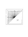
- FIG. 2 is a diagram showing candidates for the intra-prediction mode of the luminance block according to the present embodiment.
- the candidates for the intra prediction mode used for the luminance block among the blocks to be encoded are shown.
- FIG. 2 there are 67 prediction modes from 0 to 66.
- the mode "0" of the prediction mode is Planar prediction
- the mode "1" of the prediction mode is DC prediction
- the modes "2" to "66” of the prediction mode are direction prediction.
- the direction of the arrow indicates the reference direction
- the starting point of the arrow indicates the position of the pixel to be predicted
- the end point of the arrow indicates the position of the reference pixel used to predict the pixel to be predicted.
- mode "2" which is a prediction mode for referring to the lower left direction
- mode "66” which is a prediction mode for referring to the upper right direction.
- Mode numbers are assigned to each predetermined angle clockwise from “2" to the mode "66".
- the number of candidates for the intra-prediction mode of the color difference block is smaller than the number of candidates for the intra-prediction mode of the luminance block.
- the intra prediction unit 172 determines the intra prediction mode used for the intra prediction of the brightness block at the position corresponding to the position of the color difference block as the first candidate mode in the intra prediction of the color difference block.
- the second candidate mode that does not overlap with the first candidate mode is determined, and the intra prediction mode used for the intra prediction of the color difference block is selected from these candidate modes.
- DM Direct Mode or Delivered Mode
- the intra prediction unit 172 replaces the overlapping default mode with the second candidate mode.
- the default modes are Planar mode (mode 0), vertical mode (mode 50), horizontal mode (mode 18), and DC mode (mode 1).
- mode 66 a fixed intra prediction mode other than the default mode, for example, mode 66 is used.
- the luminance block at the position corresponding to the position of the color difference block means the luminance block at the same position as the position of the color difference block when the block division shape of the luminance block and the luminance block is the same.
- the brightness block at the position corresponding to the position of the color difference block is a predetermined pixel position (for example, color difference) in the color difference block.
- a brightness block containing coordinates corresponding to (such as the coordinates at the upper left of the block).
- the coordinates corresponding to the predetermined pixel positions in the color difference block are not necessarily the same coordinates because the brightness and the size of the color difference may differ in the color difference format such as 4: 2: 0.
- CCLM inter-component linear model prediction
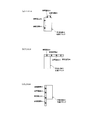
- FIG. 3 is a diagram showing three CCLM modes according to the present embodiment.
- FIG. 3 shows an example in which the linear model calculation pixel positions are four pixel positions.
- the LT_CCLM mode shown in FIG. 3A is a CCLM mode in which both the upper and left positions of the color difference block to be predicted are the linear model calculation pixel positions.
- the intra prediction unit 172 shows the upper side and the left side as shown in FIG. 3A.
- a linear model is calculated using reference pixels # 1 to # 4.
- the T_CCLM mode shown in FIG. 3B is a CCLM mode in which the position above the color difference block to be predicted is the linear model calculation pixel position.
- the intra prediction unit 172 selects the upper reference pixels # 1 to # shown in FIG. 3 (b).
- a linear model is calculated using 4.
- the L_CCLM mode shown in FIG. 3C is a CCLM mode in which the position on the left side of the color difference block to be predicted is the linear model calculation pixel position.
- the intra prediction unit 172 selects the reference pixels # 1 to # on the left side shown in FIG. 3C.
- a linear model is calculated using 4.
- the intra prediction unit 172 has an inter-component linear model prediction unit 1721 that predicts the color difference block to be predicted by CCLM.
- FIG. 4 is a diagram showing the configuration of the inter-component linear model prediction unit 1721 according to the present embodiment.
- the inter-component linear model prediction unit 1721 includes a luminance intra prediction mode acquisition unit 1721a, a reference pixel position selection unit 1721b, a reference pixel acquisition unit 1721c, a linear model calculation unit 1721d, and a color difference prediction pixel. It has a generation unit 1721e.
- the luminance intra prediction mode acquisition unit 1721a acquires the luminance intra prediction mode, which is an intra prediction mode applied to the decoded brightness block at the position corresponding to the position of the color difference block to be predicted, from the memory 160. Specifically, the luminance intra prediction mode acquisition unit 1721a acquires the mode number (any of 0 to 66) of the luminance intra prediction mode, and outputs the acquired mode number to the reference pixel position selection unit 1721b.
- the luminance intra prediction mode acquisition unit 1721a corresponds to the case where the inter-prediction is applied to the decoded brightness block at the position corresponding to the position of the color difference block to be predicted, or the position of the color difference block to be predicted. If the luminance block at the position has not been decoded (that is, it has not been decoded), information to that effect is output to the reference pixel position selection unit 1721b.
- the reference pixel position selection unit 1721b selects the linear model calculation pixel position, which is the position of the reference pixel used for calculating the linear model, based on the brightness intra prediction mode acquired by the brightness intra prediction mode acquisition unit 1721a.
- the reference pixel position selection unit 1721b is a color difference block to be predicted from the above-mentioned three CCLM modes based on the mode number of the brightness intra prediction mode output from the brightness intra prediction mode acquisition unit 1721a.
- One CCLM mode to be applied to is selected, and CCLM mode information indicating the selected CCLM mode is output to the reference pixel acquisition unit 1721c.
- the linear model calculation pixel position is selected based on the luminance intra prediction mode. It is supposed to be. For example, when an intra prediction mode is applied in which intra prediction is performed using only the reference pixels located on the left side of the luminance block, only the reference pixels on the left side are used for the intra prediction of the corresponding color difference block. It is likely that a CCLM mode (ie, L_CCLM mode) that calculates a linear model will be used.
- CCLM mode ie, L_CCLM mode
- the luminance intra prediction mode is information that can be used by both the image coding device 1 and the image decoding device. Therefore, in both the image coding device 1 and the image decoding device, the CCLM mode information is transferred from the image coding device to the image decoding device side by implicitly selecting the linear model calculation pixel position based on the brightness intra prediction mode. There is no need to transmit to. Therefore, it is possible to suppress an increase in additional information to be transmitted, and it is possible to improve the coding efficiency.
- the reference pixel position selection unit 1721b when the luminance intra prediction mode is the intra prediction mode in which the reference pixels on both the upper side and the left side of the luminance block are referred to, the reference pixel position selection unit 1721b is used on both the upper side and the left side of the color difference block to be predicted. Select the position of as the linear model calculation pixel position. In other words, the reference pixel position selection unit 1721b selects the LT_CCLM mode when the luminance intra prediction mode is the intra prediction mode that refers to both the upper and left reference pixels of the luminance block.
- the luminance intra prediction mode is an intra prediction mode that refers to both the upper and left reference pixels of the luminance block, for example, assuming a square luminance block in VVC, the mode number of the luminance intra prediction mode is 0 ( Planar prediction mode), 1 (DC prediction mode), and direction prediction mode from 19 to 49.
- the reference pixel position selection unit 1721b of the color difference block to be predicted. Select the upper position as the linear model calculation pixel position.
- the reference pixel position selection unit 1721b selects the T_CCLM mode when the luminance intra-prediction mode is the intra-prediction mode in which the reference pixel on the upper side of the luminance block is referred to without referring to the reference pixel on the left side of the luminance block. ..
- the luminance intra prediction mode is the intra-prediction mode in which the reference pixel on the upper side of the luminance block is referred to without referring to the reference pixel on the left side of the luminance block, for example, assuming a square luminance block in VVC, the luminance intra is assumed. This refers to the case where the mode number of the prediction mode is any of 50 to 66.
- the reference pixel position selection unit 1721b of the color difference block to be predicted. Select the position on the left as the linear model calculation pixel position. In other words, the reference pixel position selection unit 1721b selects the L_CCLM mode when the luminance intra-prediction mode is the intra-prediction mode in which the reference pixel on the left side of the luminance block is referred to without referring to the reference pixel on the upper side of the luminance block. ..
- the luminance intra prediction mode is the intra-prediction mode in which the reference pixel on the left side of the luminance block is referred to without referring to the reference pixel on the upper side of the luminance block, for example, assuming a square luminance block in VVC, the luminance intra is assumed. This refers to the case where the mode number of the prediction mode is any of 2 to 18.
- the reference pixel position selection unit 1721b uses a predetermined reference when the inter-prediction is applied to the decoded brightness block or when the brightness block at the position corresponding to the position of the color difference block is not decoded. Select the pixel position as the linear model calculation pixel position. For example, the reference pixel position selection unit 1721b selects the LT_CCLM mode when the inter-prediction is applied to the decoded luminance block, or when the luminance block at the position corresponding to the position of the color difference block is not decoded. ..
- the reference pixel acquisition unit 1721c stores the reference pixels having the brightness and color difference at the linear model calculation pixel positions selected by the reference pixel position selection unit 1721b based on the CCLM mode information output from the reference pixel position selection unit 1721b. And each acquired reference pixel is output to the linear model calculation unit 1721d.
- the reference pixel acquisition unit 1721c acquires four adjacent color difference pixels and the corresponding downsampled luminance pixels. Specifically, the reference pixel acquisition unit 1721c determines the positions of four adjacent pixels by the following equation (1).
- the linear model calculation unit 1721d calculates a linear model using each reference pixel output from the reference pixel acquisition unit 1721c (specifically, a reference pixel having four color differences and a reference pixel having four luminances corresponding thereto). To do.
- the linear model calculation unit 1721d compares the reference pixels of four luminances with each other and identifies two small values (x 0 A , x 1 A ) and two large values (x 0 B , x 1 B ). Then, the reference pixels of the color difference corresponding to them are specified as y 0 A , y 1 A , y 0 B , and y 1 B.
- the linear model calculation unit 1721d is, X a by the following equation (2), X b, Y a, and calculates the Y b.
- the linear model calculation unit 1721d calculates the parameters ⁇ and ⁇ of the linear model by the following equation (3), and outputs the calculated parameters ⁇ and ⁇ of the linear model to the color difference prediction pixel generation unit 1721e.
- the color difference prediction pixel generation unit 1721e generates prediction pixels in the color difference block to be predicted by using the linear model (parameters ⁇ and ⁇ ) calculated by the linear model calculation unit 1721d, and the color difference prediction consisting of the generated prediction pixels. Output the block. For example, the color difference prediction pixel generation unit 1721e calculates each prediction pixel pred C (i, j) of the color difference by the following equation (4).
- i and j indicate the coordinate positions in the horizontal direction and the vertical direction, respectively.
- rec L '(i, j) is a filter processing of downsampled decoded pixels in the decoded luminance block at the position corresponding to the color difference block to be predicted.
- the intra prediction unit 172 outputs a color difference prediction block.
- the intra prediction unit 172 may output information indicating that CCLM has been applied to the entropy encoding unit 130, and determines which mode of CCLM is selected. It is not necessary to output the indicated CCLM mode information to the entropy encoding unit 130.
- FIG. 5 is a diagram showing a configuration of an image decoding device 2 according to the present embodiment.
- the image decoding device 2 includes an entropy decoding unit 200, an inverse quantization / inverse conversion unit 210, a synthesis unit 220, a memory 230, and a prediction unit 240.
- the entropy decoding unit 200 decodes the coded data generated by the image coding device 1 and outputs the quantized orthogonal transformation coefficient to the inverse quantization / inverse transformation unit 210. Further, the entropy decoding unit 200 acquires information on prediction (intra-prediction and inter-prediction), and outputs the acquired information to the prediction unit 240. In the present embodiment, the entropy decoding unit 200 acquires information indicating that CCLM has been applied to the color difference block, and outputs the acquired information to the prediction unit 240 (intra prediction unit 242).
- the inverse quantization / inverse transformation unit 210 performs inverse quantization processing and inverse orthogonal transformation processing in block units.
- the inverse quantization / inverse conversion unit 210 includes an inverse quantization unit 211 and an inverse conversion unit 212.
- the inverse quantization unit 211 performs the inverse quantization process corresponding to the quantization process performed by the quantization unit 122 of the image coding device 1.
- the inverse quantization unit 211 reverse-quantizes the quantization orthogonal conversion coefficient output from the entropy decoding unit 200 using the quantization parameter (Qp) and the quantization matrix to obtain the orthogonal transformation coefficient of the block to be decoded. It is restored, and the restored orthogonal transformation coefficient is output to the inverse conversion unit 212.
- the inverse conversion unit 212 performs an inverse orthogonal transformation process corresponding to the orthogonal transformation process performed by the conversion unit 121 of the image coding device 1.
- the inverse conversion unit 212 performs an inverse orthogonal transformation process on the orthogonal transformation coefficient output from the inverse quantization unit 211 to restore the predicted residual, and the restored predicted residual (restored predicted residual) is combined with the combining unit 220. Output to.
- the synthesis unit 220 decodes (reconstructs) the original block by synthesizing the prediction residual output from the inverse conversion unit 212 and the prediction block output from the prediction unit 240 on a pixel-by-pixel basis, and has already been decoded.
- the block is output to the memory 230.
- the memory 230 stores the decoded blocks output from the compositing unit 220, and stores the decoded blocks as a decoded image in frame units.
- the memory 230 outputs the decoded block or the decoded image to the prediction unit 240. Further, the memory 230 outputs the decoded image in frame units to the outside of the image decoding device 2.
- a loop filter may be provided between the compositing unit 220 and the memory 230.
- the prediction unit 240 makes a prediction in block units.
- the prediction unit 240 has an inter prediction unit 241, an intra prediction unit 242, and a switching unit 243.
- the intra prediction unit 242 corresponds to the intra prediction device provided in the image decoding device 2.
- the inter-prediction unit 241 predicts the decoding target block by inter-prediction using the decoded image stored in the memory 230 as a reference image.
- the inter-prediction unit 241 generates an inter-prediction block by performing inter-prediction according to motion vector information or the like output from the entropy decoding unit 200, and outputs the generated inter-prediction block to the switching unit 243.
- the intra prediction unit 242 generates an intra prediction block by referring to the decoded pixels around the prediction target block (decoding target block) among the decoded images stored in the memory 230, and the generated intra prediction block. Is output to the switching unit 243.
- the intra prediction unit 242 corresponds to an intra prediction device provided in the image decoding device 2.
- the intra prediction unit 242 has an inter-component linear model prediction unit 2421.
- the switching unit 243 switches between the inter prediction block output from the inter prediction unit 241 and the intra prediction block output from the intra prediction unit 242, and outputs one of the prediction blocks to the synthesis unit 220.
- FIG. 6 is a diagram showing the configuration of the inter-component linear model prediction unit 2421 of the image decoding device 2 according to the present embodiment.
- the inter-component linear model prediction unit 2421 includes a luminance intra prediction mode acquisition unit 2421a, a reference pixel position selection unit 2421b, a reference pixel acquisition unit 2421c, a linear model calculation unit 2421d, and a color difference prediction pixel. It has a generation unit 2421e.
- the brightness intra prediction mode acquisition unit 2421a, the reference pixel position selection unit 2421b, the reference pixel acquisition unit 2421c, the linear model calculation unit 2421d, and the color difference prediction pixel generation unit 2421e refer to the brightness intra prediction mode acquisition unit 1721a shown in FIG.
- the same operations as those of the pixel position selection unit 1721b, the reference pixel acquisition unit 1721c, the linear model calculation unit 1721d, and the color difference prediction pixel generation unit 1721e are performed.
- Example of intra-prediction operation flow Next, an example of the operation flow of the intra prediction according to the present embodiment will be described.
- the operation of the intra prediction is the same in the image coding device 1 and the image decoding device 2, but here, the operation of the intra prediction (intra prediction unit 242) in the image decoding device 2 will be described.
- FIG. 7 is a diagram showing the operation of the intra prediction (intra prediction unit 242) in the image decoding device 2 according to the present embodiment.
- the intra-prediction unit 242 sets the candidate for the intra-prediction mode of a certain color difference block to the position [xCb + cbWith / 2] Generated based on the intraprediction mode IntraPredModeY of the luminance block in [yCb + cbHeight / 2].
- X corresponds to DM and Y corresponds to CCLM.
- the CCLM mode information that identifies the three modes of CCLM is not transmitted. Therefore, the information intra_chroma_pred_mode indicating the intra prediction mode applied to the color difference block may be transmitted from the image coding device 1 to the image decoding device 2 without transmitting the CCLM mode information.
- intra_chroma_pred_mode as shown in Table 2, the shortest symbol length is assigned to DM, and the next shortest symbol length is assigned to CCLM.
- step S1 the luminance intra-prediction mode acquisition unit 2421a determines whether or not the intra-prediction is applied to the decoded brightness block at the position corresponding to the position of the color difference block to be predicted. To do. When inter-prediction is applied to the decoded brightness block at the position corresponding to the position of the color difference block to be predicted, or the brightness block at the position corresponding to the position of the color difference block to be predicted is not decoded ( That is, if it is undecrypted), the process proceeds to step S8.
- step S2 the brightness intra-prediction mode acquisition unit 2421a is the prediction target.
- the luminance intra prediction mode which is the intra prediction mode applied to the decoded brightness block at the position corresponding to the position of the color difference block, is acquired from the memory 230.
- the luminance intra prediction mode acquisition unit 2421a acquires the mode number (any of 0 to 66) of the luminance intra prediction mode, and outputs the acquired mode number to the reference pixel position selection unit 2421b.
- the mode number of the intra prediction mode is replaced by WAIP (Wide Angle Intra Precision). Therefore, the mode number after this replacement is performed is used as the mode number of the luminance intra prediction mode.
- step S3 the reference pixel position selection unit 2421b determines whether or not the luminance intra prediction mode is the intra prediction mode that refers to both the upper and left reference pixels of the luminance block.
- step S4 the reference pixel position selection unit 2421b selects both the upper side and the left side position of the color difference block to be predicted as the linear model calculation pixel position. That is, the LT_CCLM mode is selected.
- the reference pixel position selection unit 2421b refers to the reference pixel on the upper side of the luminance block without referring to the reference pixel on the left side of the luminance block in the luminance intra prediction mode. Determine if it is in the prediction mode. If "YES” in step S5, in step S6, the reference pixel position selection unit 2421b selects the position above the color difference block to be predicted as the linear model calculation pixel position, that is, selects the T_CCLM mode.
- step S5 specifically, when the luminance intra-prediction mode is an intra-prediction mode in which the reference pixel on the left side of the luminance block is referred to without referring to the reference pixel on the upper side of the luminance block, the step.
- the reference pixel position selection unit 2421b selects the position on the left side of the color difference block to be predicted as the linear model calculation pixel position, that is, selects the L_CCLM mode.
- step S8 the reference pixel position selection unit 2421b selects a predetermined reference pixel position as the linear model calculation pixel position, for example, the LT_CCLM mode.
- step S9 the reference pixel acquisition unit 2421c is set to the linear model calculation pixel position selected by the reference pixel position selection unit 2421b according to the above equation (1).
- Reference pixels with a certain brightness and color difference are acquired from the memory 230, and each acquired reference pixel is output to the linear model calculation unit 2421d.
- step S10 the linear model calculation unit 2421d uses each reference pixel (specifically, a reference pixel having four color differences and a reference pixel having four brightness corresponding thereto) output from the reference pixel acquisition unit 2421c.
- the linear model is calculated by the above equations (2) and (3).
- step S11 the color difference prediction pixel generation unit 2421e uses the linear model (parameters ⁇ and ⁇ ) calculated by the linear model calculation unit 2421d to generate the prediction pixels in the color difference block to be predicted by the above equation (4). Generate and output a color difference prediction block consisting of the generated prediction pixels.
- the reference pixel position selection unit 1721b (and 2421b) is the position of the reference pixel used for calculating the linear model based on the brightness intra prediction mode acquired by the brightness intra prediction mode acquisition unit 1721a (and 2421a). Select the linear model calculation pixel position that is. Specifically, the reference pixel position selection unit 1721b (and 2421b) is selected from the three CCLM modes based on the mode number of the brightness intra prediction mode output from the brightness intra prediction mode acquisition unit 1721a (and 2421a). , Select one CCLM mode to apply to the color difference block to be predicted.
- the CCLM mode information is obtained from the image coding device 1 by implicitly selecting the linear model calculation pixel position based on the brightness intra prediction mode. There is no need to transmit to the decoding device 2. Further, in the present embodiment, paying attention to the fact that the spatial characteristics of the luminance component and the color difference component at the same position in the image are similar, it is possible to select an appropriate linear model calculation pixel position according to the luminance intra prediction mode. .. Therefore, since the color difference block can be predicted accurately by CCLM while suppressing the increase of additional information to be transmitted, the coding efficiency can be improved.
- a program that causes a computer to execute each process performed by the image coding apparatus 1 may be provided.
- a program that causes a computer to execute each process performed by the image decoding device 2 may be provided.
- the program may be recorded on a computer-readable medium.
- Computer-readable media can be used to install programs on a computer.
- the computer-readable medium on which the program is recorded may be a non-transient recording medium.
- the non-transient recording medium is not particularly limited, but may be, for example, a recording medium such as a CD-ROM or a DVD-ROM.
- a circuit that executes each process performed by the image coding device 1 may be integrated, and the image coding device 1 may be configured by a semiconductor integrated circuit (chipset, SoC).
- a circuit that executes each process performed by the image decoding device 2 may be integrated, and the image decoding device 2 may be configured by a semiconductor integrated circuit (chipset, SoC).
Landscapes
- Engineering & Computer Science (AREA)
- Multimedia (AREA)
- Signal Processing (AREA)
- Compression Or Coding Systems Of Tv Signals (AREA)
Priority Applications (3)
| Application Number | Priority Date | Filing Date | Title |
|---|---|---|---|
| JP2021558265A JPWO2021100450A1 (cg-RX-API-DMAC7.html) | 2019-11-21 | 2020-11-02 | |
| US17/749,446 US12088789B2 (en) | 2019-11-21 | 2022-05-20 | Intra prediction device, image encoding device, image decoding device and program |
| JP2024210582A JP2025029101A (ja) | 2019-11-21 | 2024-12-03 | イントラ予測装置、画像符号化装置、画像復号装置、及びプログラム |
Applications Claiming Priority (2)
| Application Number | Priority Date | Filing Date | Title |
|---|---|---|---|
| JP2019-210881 | 2019-11-21 | ||
| JP2019210881 | 2019-11-21 |
Related Child Applications (1)
| Application Number | Title | Priority Date | Filing Date |
|---|---|---|---|
| US17/749,446 Continuation US12088789B2 (en) | 2019-11-21 | 2022-05-20 | Intra prediction device, image encoding device, image decoding device and program |
Publications (1)
| Publication Number | Publication Date |
|---|---|
| WO2021100450A1 true WO2021100450A1 (ja) | 2021-05-27 |
Family
ID=75980688
Family Applications (1)
| Application Number | Title | Priority Date | Filing Date |
|---|---|---|---|
| PCT/JP2020/041100 Ceased WO2021100450A1 (ja) | 2019-11-21 | 2020-11-02 | イントラ予測装置、画像符号化装置、画像復号装置、及びプログラム |
Country Status (3)
| Country | Link |
|---|---|
| US (1) | US12088789B2 (cg-RX-API-DMAC7.html) |
| JP (2) | JPWO2021100450A1 (cg-RX-API-DMAC7.html) |
| WO (1) | WO2021100450A1 (cg-RX-API-DMAC7.html) |
Cited By (1)
| Publication number | Priority date | Publication date | Assignee | Title |
|---|---|---|---|---|
| JP2024508459A (ja) * | 2021-10-05 | 2024-02-27 | テンセント・アメリカ・エルエルシー | ビデオ復号化方法及び装置、並びにビデオ符号化方法 |
Families Citing this family (3)
| Publication number | Priority date | Publication date | Assignee | Title |
|---|---|---|---|---|
| CN115767100A (zh) * | 2022-10-14 | 2023-03-07 | 浙江大华技术股份有限公司 | 预测方法、图像编码方法、图像解码方法及装置 |
| CN119496905A (zh) * | 2023-08-20 | 2025-02-21 | 腾讯科技(深圳)有限公司 | 一种图像处理方法、装置、设备 |
| CN120658875A (zh) * | 2024-03-14 | 2025-09-16 | 腾讯科技(深圳)有限公司 | 颜色分量的预测方法、装置、介质及电子设备 |
Citations (2)
| Publication number | Priority date | Publication date | Assignee | Title |
|---|---|---|---|---|
| WO2015005418A1 (ja) * | 2013-07-10 | 2015-01-15 | Kddi株式会社 | 動画像符号化装置、動画像復号装置、動画像システム、動画像符号化方法、動画像復号方法、およびプログラム |
| WO2019221465A1 (ko) * | 2018-05-14 | 2019-11-21 | 인텔렉추얼디스커버리 주식회사 | 영상 복호화 방법/장치, 영상 부호화 방법/장치 및 비트스트림을 저장한 기록 매체 |
Family Cites Families (11)
| Publication number | Priority date | Publication date | Assignee | Title |
|---|---|---|---|---|
| GB2567249A (en) * | 2017-10-09 | 2019-04-10 | Canon Kk | New sample sets and new down-sampling schemes for linear component sample prediction |
| US11394961B2 (en) * | 2018-10-04 | 2022-07-19 | Lg Electronics Inc. | CCLM-based intra-prediction method and apparatus therefor |
| EP3850853A4 (en) * | 2018-10-05 | 2022-08-10 | Huawei Technologies Co., Ltd. | Intra prediction method and device |
| KR20260019015A (ko) * | 2018-12-21 | 2026-02-09 | 삼성전자주식회사 | 부호화 방법 및 그 장치, 복호화 방법 및 그 장치 |
| WO2020149616A1 (ko) * | 2019-01-14 | 2020-07-23 | 엘지전자 주식회사 | 영상 코딩 시스템에서 cclm 예측 기반 영상 디코딩 방법 및 그 장치 |
| MX2021012472A (es) * | 2019-04-18 | 2021-11-12 | Beijing Bytedance Network Tech Co Ltd | Restriccion de la aplicabilidad del modo de componentes cruzados. |
| SG11202110999PA (en) * | 2019-04-23 | 2021-11-29 | Beijing Bytedance Network Technology Co Ltd | Methods for cross component dependency reduction |
| WO2020224629A1 (en) * | 2019-05-08 | 2020-11-12 | Beijing Bytedance Network Technology Co., Ltd. | Conditions for applicability of cross-component coding |
| CN117499641A (zh) * | 2019-05-10 | 2024-02-02 | 北京字节跳动网络技术有限公司 | 用于视频处理的简化二次变换的有条件使用 |
| CN113994697B (zh) * | 2019-06-22 | 2024-10-18 | 北京字节跳动网络技术有限公司 | 色度残差缩放的语法元素 |
| JP7460748B2 (ja) * | 2019-07-07 | 2024-04-02 | 北京字節跳動網絡技術有限公司 | クロマ残差スケーリングのシグナリング |
-
2020
- 2020-11-02 JP JP2021558265A patent/JPWO2021100450A1/ja active Pending
- 2020-11-02 WO PCT/JP2020/041100 patent/WO2021100450A1/ja not_active Ceased
-
2022
- 2022-05-20 US US17/749,446 patent/US12088789B2/en active Active
-
2024
- 2024-12-03 JP JP2024210582A patent/JP2025029101A/ja active Pending
Patent Citations (2)
| Publication number | Priority date | Publication date | Assignee | Title |
|---|---|---|---|---|
| WO2015005418A1 (ja) * | 2013-07-10 | 2015-01-15 | Kddi株式会社 | 動画像符号化装置、動画像復号装置、動画像システム、動画像符号化方法、動画像復号方法、およびプログラム |
| WO2019221465A1 (ko) * | 2018-05-14 | 2019-11-21 | 인텔렉추얼디스커버리 주식회사 | 영상 복호화 방법/장치, 영상 부호화 방법/장치 및 비트스트림을 저장한 기록 매체 |
Non-Patent Citations (2)
| Title |
|---|
| KEI KAWAMURA ET AL.: "Non-RCE1: Chroma intra prediction with mode-dependent reduced reference", JOINT COLLABORATIVE TEAM ON VIDEO CODING (JCT-VC) OF ITU-T SG 16 WP 3 AND ISO/IEC JTC 1/SC 29/WG 11, JCTVC-N0368_R1, 14TH MEETING, July 2013 (2013-07-01), Vienna, AT, pages 1 - 5, XP030238154 * |
| XIANG MA ET AL.: "CE3: CCLM/MDLM using simplified coefficients derivation method (Test 5.6.1, 5.6.2 and 5.6.3)", JOINT VIDEO EXPERTS TEAM (JVET) OF ITU-T SG 16 WP 3 AND ISO/IEC JTC 1/SC 29/WG 11, JVET- L0340_R1, 12TH MEETING, September 2018 (2018-09-01), Macao, CN, pages 1 - 6 * |
Cited By (2)
| Publication number | Priority date | Publication date | Assignee | Title |
|---|---|---|---|---|
| JP2024508459A (ja) * | 2021-10-05 | 2024-02-27 | テンセント・アメリカ・エルエルシー | ビデオ復号化方法及び装置、並びにビデオ符号化方法 |
| JP7686765B2 (ja) | 2021-10-05 | 2025-06-02 | テンセント・アメリカ・エルエルシー | ビデオ復号化方法及び装置、並びにビデオ符号化方法 |
Also Published As
| Publication number | Publication date |
|---|---|
| US20220279170A1 (en) | 2022-09-01 |
| US12088789B2 (en) | 2024-09-10 |
| JP2025029101A (ja) | 2025-03-05 |
| JPWO2021100450A1 (cg-RX-API-DMAC7.html) | 2021-05-27 |
Similar Documents
| Publication | Publication Date | Title |
|---|---|---|
| KR102064154B1 (ko) | 휘도 샘플을 이용한 색차 블록의 화면 내 예측 방법 및 이러한 방법을 사용하는 장치 | |
| US11695955B2 (en) | Image encoding device, image decoding device and program | |
| JP7357736B2 (ja) | 符号化装置、復号装置、及びプログラム | |
| US12088789B2 (en) | Intra prediction device, image encoding device, image decoding device and program | |
| JP2022172137A (ja) | 適応乗算係数を用いた画像フィルタリングのための方法および装置 | |
| JP7636493B2 (ja) | 符号化装置、復号装置、及びプログラム | |
| JP7415067B2 (ja) | イントラ予測装置、画像復号装置、及びプログラム | |
| JP2020028066A (ja) | 色差イントラ予測候補生成装置、画像符号化装置、画像復号装置、及びプログラム | |
| JP7768746B2 (ja) | イントラ予測装置、復号装置、及びプログラム | |
| JP2023138826A (ja) | イントラ予測装置、画像符号化装置、画像復号装置、及びプログラム | |
| JPWO2020036130A1 (ja) | イントラ予測装置、画像符号化装置、画像復号装置、及びプログラム | |
| JP7531683B2 (ja) | 符号化装置、復号装置、及びプログラム | |
| JP7361498B2 (ja) | イントラ予測装置、画像符号化装置、画像復号装置、及びプログラム | |
| JP2020109960A (ja) | イントラ予測装置、画像符号化装置、画像復号装置、及びプログラム |
Legal Events
| Date | Code | Title | Description |
|---|---|---|---|
| 121 | Ep: the epo has been informed by wipo that ep was designated in this application |
Ref document number: 20890391 Country of ref document: EP Kind code of ref document: A1 |
|
| ENP | Entry into the national phase |
Ref document number: 2021558265 Country of ref document: JP Kind code of ref document: A |
|
| NENP | Non-entry into the national phase |
Ref country code: DE |
|
| 122 | Ep: pct application non-entry in european phase |
Ref document number: 20890391 Country of ref document: EP Kind code of ref document: A1 |
|
| WWG | Wipo information: grant in national office |
Ref document number: 202217028984 Country of ref document: IN |