WO2021100328A1 - Procédé, dispositif et système de traitement d'images - Google Patents
Procédé, dispositif et système de traitement d'images Download PDFInfo
- Publication number
- WO2021100328A1 WO2021100328A1 PCT/JP2020/037068 JP2020037068W WO2021100328A1 WO 2021100328 A1 WO2021100328 A1 WO 2021100328A1 JP 2020037068 W JP2020037068 W JP 2020037068W WO 2021100328 A1 WO2021100328 A1 WO 2021100328A1
- Authority
- WO
- WIPO (PCT)
- Prior art keywords
- image
- image processing
- medical image
- focusing
- filter
- Prior art date
Links
- 238000003672 processing method Methods 0.000 title claims abstract description 30
- 238000003384 imaging method Methods 0.000 claims description 29
- 239000002131 composite material Substances 0.000 claims description 13
- 239000000203 mixture Substances 0.000 claims description 10
- 230000002093 peripheral effect Effects 0.000 claims description 6
- 238000009499 grossing Methods 0.000 claims description 4
- 239000000463 material Substances 0.000 claims description 4
- 230000007170 pathology Effects 0.000 claims description 4
- 230000006870 function Effects 0.000 description 34
- 238000004364 calculation method Methods 0.000 description 26
- 238000000879 optical micrograph Methods 0.000 description 23
- 238000000034 method Methods 0.000 description 19
- 230000010365 information processing Effects 0.000 description 16
- 238000004891 communication Methods 0.000 description 15
- 210000004027 cell Anatomy 0.000 description 14
- 230000003287 optical effect Effects 0.000 description 10
- 230000008569 process Effects 0.000 description 10
- 230000015572 biosynthetic process Effects 0.000 description 9
- 238000003786 synthesis reaction Methods 0.000 description 9
- 210000001519 tissue Anatomy 0.000 description 8
- 238000010586 diagram Methods 0.000 description 6
- 230000004048 modification Effects 0.000 description 5
- 238000012986 modification Methods 0.000 description 5
- 238000003745 diagnosis Methods 0.000 description 4
- 230000000694 effects Effects 0.000 description 4
- 239000011521 glass Substances 0.000 description 4
- 210000004698 lymphocyte Anatomy 0.000 description 4
- 230000002194 synthesizing effect Effects 0.000 description 4
- 210000002540 macrophage Anatomy 0.000 description 3
- 239000004065 semiconductor Substances 0.000 description 3
- 241000590002 Helicobacter pylori Species 0.000 description 2
- 210000003855 cell nucleus Anatomy 0.000 description 2
- 230000008859 change Effects 0.000 description 2
- 238000001914 filtration Methods 0.000 description 2
- 229940037467 helicobacter pylori Drugs 0.000 description 2
- 230000010354 integration Effects 0.000 description 2
- 239000004973 liquid crystal related substance Substances 0.000 description 2
- 230000009471 action Effects 0.000 description 1
- 230000006835 compression Effects 0.000 description 1
- 238000007906 compression Methods 0.000 description 1
- 239000006059 cover glass Substances 0.000 description 1
- 230000006866 deterioration Effects 0.000 description 1
- 201000010099 disease Diseases 0.000 description 1
- 208000037265 diseases, disorders, signs and symptoms Diseases 0.000 description 1
- 238000005516 engineering process Methods 0.000 description 1
- 230000002068 genetic effect Effects 0.000 description 1
- 210000003097 mucus Anatomy 0.000 description 1
- 238000010827 pathological analysis Methods 0.000 description 1
- 238000010079 rubber tapping Methods 0.000 description 1
- 230000000007 visual effect Effects 0.000 description 1
Images


Classifications
-
- G—PHYSICS
- G02—OPTICS
- G02B—OPTICAL ELEMENTS, SYSTEMS OR APPARATUS
- G02B21/00—Microscopes
- G02B21/36—Microscopes arranged for photographic purposes or projection purposes or digital imaging or video purposes including associated control and data processing arrangements
- G02B21/365—Control or image processing arrangements for digital or video microscopes
- G02B21/367—Control or image processing arrangements for digital or video microscopes providing an output produced by processing a plurality of individual source images, e.g. image tiling, montage, composite images, depth sectioning, image comparison
-
- G—PHYSICS
- G06—COMPUTING; CALCULATING OR COUNTING
- G06T—IMAGE DATA PROCESSING OR GENERATION, IN GENERAL
- G06T5/00—Image enhancement or restoration
- G06T5/20—Image enhancement or restoration using local operators
-
- G—PHYSICS
- G02—OPTICS
- G02B—OPTICAL ELEMENTS, SYSTEMS OR APPARATUS
- G02B21/00—Microscopes
- G02B21/36—Microscopes arranged for photographic purposes or projection purposes or digital imaging or video purposes including associated control and data processing arrangements
- G02B21/365—Control or image processing arrangements for digital or video microscopes
-
- G—PHYSICS
- G06—COMPUTING; CALCULATING OR COUNTING
- G06T—IMAGE DATA PROCESSING OR GENERATION, IN GENERAL
- G06T5/00—Image enhancement or restoration
- G06T5/50—Image enhancement or restoration using two or more images, e.g. averaging or subtraction
-
- G—PHYSICS
- G06—COMPUTING; CALCULATING OR COUNTING
- G06T—IMAGE DATA PROCESSING OR GENERATION, IN GENERAL
- G06T5/00—Image enhancement or restoration
- G06T5/70—Denoising; Smoothing
-
- G—PHYSICS
- G06—COMPUTING; CALCULATING OR COUNTING
- G06T—IMAGE DATA PROCESSING OR GENERATION, IN GENERAL
- G06T5/00—Image enhancement or restoration
- G06T5/73—Deblurring; Sharpening
-
- G—PHYSICS
- G06—COMPUTING; CALCULATING OR COUNTING
- G06T—IMAGE DATA PROCESSING OR GENERATION, IN GENERAL
- G06T7/00—Image analysis
- G06T7/0002—Inspection of images, e.g. flaw detection
- G06T7/0012—Biomedical image inspection
-
- G—PHYSICS
- G06—COMPUTING; CALCULATING OR COUNTING
- G06T—IMAGE DATA PROCESSING OR GENERATION, IN GENERAL
- G06T2207/00—Indexing scheme for image analysis or image enhancement
- G06T2207/10—Image acquisition modality
- G06T2207/10004—Still image; Photographic image
- G06T2207/10012—Stereo images
-
- G—PHYSICS
- G06—COMPUTING; CALCULATING OR COUNTING
- G06T—IMAGE DATA PROCESSING OR GENERATION, IN GENERAL
- G06T2207/00—Indexing scheme for image analysis or image enhancement
- G06T2207/10—Image acquisition modality
- G06T2207/10056—Microscopic image
-
- G—PHYSICS
- G06—COMPUTING; CALCULATING OR COUNTING
- G06T—IMAGE DATA PROCESSING OR GENERATION, IN GENERAL
- G06T2207/00—Indexing scheme for image analysis or image enhancement
- G06T2207/20—Special algorithmic details
- G06T2207/20004—Adaptive image processing
- G06T2207/20008—Globally adaptive
-
- G—PHYSICS
- G06—COMPUTING; CALCULATING OR COUNTING
- G06T—IMAGE DATA PROCESSING OR GENERATION, IN GENERAL
- G06T2207/00—Indexing scheme for image analysis or image enhancement
- G06T2207/20—Special algorithmic details
- G06T2207/20172—Image enhancement details
- G06T2207/20182—Noise reduction or smoothing in the temporal domain; Spatio-temporal filtering
-
- G—PHYSICS
- G06—COMPUTING; CALCULATING OR COUNTING
- G06T—IMAGE DATA PROCESSING OR GENERATION, IN GENERAL
- G06T2207/00—Indexing scheme for image analysis or image enhancement
- G06T2207/20—Special algorithmic details
- G06T2207/20172—Image enhancement details
- G06T2207/20192—Edge enhancement; Edge preservation
-
- G—PHYSICS
- G06—COMPUTING; CALCULATING OR COUNTING
- G06T—IMAGE DATA PROCESSING OR GENERATION, IN GENERAL
- G06T2207/00—Indexing scheme for image analysis or image enhancement
- G06T2207/20—Special algorithmic details
- G06T2207/20212—Image combination
-
- G—PHYSICS
- G06—COMPUTING; CALCULATING OR COUNTING
- G06T—IMAGE DATA PROCESSING OR GENERATION, IN GENERAL
- G06T2207/00—Indexing scheme for image analysis or image enhancement
- G06T2207/20—Special algorithmic details
- G06T2207/20212—Image combination
- G06T2207/20221—Image fusion; Image merging
-
- G—PHYSICS
- G06—COMPUTING; CALCULATING OR COUNTING
- G06T—IMAGE DATA PROCESSING OR GENERATION, IN GENERAL
- G06T2207/00—Indexing scheme for image analysis or image enhancement
- G06T2207/30—Subject of image; Context of image processing
- G06T2207/30004—Biomedical image processing
-
- G—PHYSICS
- G06—COMPUTING; CALCULATING OR COUNTING
- G06T—IMAGE DATA PROCESSING OR GENERATION, IN GENERAL
- G06T2207/00—Indexing scheme for image analysis or image enhancement
- G06T2207/30—Subject of image; Context of image processing
- G06T2207/30004—Biomedical image processing
- G06T2207/30024—Cell structures in vitro; Tissue sections in vitro
-
- G—PHYSICS
- G06—COMPUTING; CALCULATING OR COUNTING
- G06T—IMAGE DATA PROCESSING OR GENERATION, IN GENERAL
- G06T2207/00—Indexing scheme for image analysis or image enhancement
- G06T2207/30—Subject of image; Context of image processing
- G06T2207/30168—Image quality inspection
Definitions
- the present invention relates to an image processing method, an image processing device, and an image processing system.
- a microscope device for observing cell tissue to image the cell tissue, save it as a medical image, and perform pathological diagnosis using the image data of the medical image.
- a digital microscope device in order to observe the entire sample, a small area on a slide glass that divides the area containing the sample is imaged by a magnifying imaging system, and a plurality of images for each small area are joined together to form one huge image. Create medical images.
- Autofocus is adopted as the focusing method that focuses the objective lens of the magnifying image system on the cell tissue to be imaged. For example, when the focal position of the objective lens of the magnifying image pickup system is moved in the optical axis direction at predetermined intervals, imaging is performed at each moving position, and the image having the highest contrast among the captured images is captured.
- a focusing method for detecting a position as a focusing position has been proposed (see, for example, Patent Document 1). This type of focusing method is called "contrast AF".
- the cell tissue image captured in this way can obtain relatively high focal accuracy, it looks different from the optical microscope image observed by an observer such as a doctor through an optical microscope.
- the purpose of this technique is to provide a digital microscope device capable of acquiring images of cell tissues with high quality, an imaging method and a program thereof.
- the image processing method is characterized in that a medical image captured by an imaging device is acquired and the strength of a filter applied to the medical image is determined according to the degree of focusing of the medical image.
- the embodiment a mode for implementing the image processing method, the image processing device, and the image processing system according to the present application (hereinafter, referred to as “the embodiment”) will be described in detail with reference to the drawings.
- the image processing method, the image processing apparatus, and the image processing system according to the present application are not limited by this embodiment. Further, in each of the following embodiments, the same parts are designated by the same reference numerals, and duplicate description is omitted.
- FIG. 1 shows the characteristics of an optical microscope image.
- Optical microscope images have different characteristics than images observed through a digital microscope device.
- FIG. 1 there are several indicators regarding the image quality of the optical microscope image.
- the characteristics of the optical microscope image will be described with reference to the index shown in FIG.
- there is an index indicating the brightness of the image quality in this embodiment, it may be expressed as "glittering feeling”
- there is an index indicating the degree of edge of image quality in this embodiment, it may be expressed as "clearness”
- the indexes showing the characteristics of the optical microscope image are, for example, “three-dimensional / planar”, “transparent / dull”, “clear / blurred” and the like.
- the blur (blurring) according to the embodiment indicates that the image is not sharp. Specifically, the blur according to the embodiment indicates a state in which the image is out of focus and is not sharp beyond the range of the depth of field.
- the in-focus according to the embodiment indicates a state in which the subject is in focus within the range of the depth of field.
- the degree of focusing according to the embodiment is a value obtained by scoring how much the focus is.
- the optical microscope image is three-dimensional.
- the three-dimensional aspect according to the embodiment indicates the quality regarding the visual contrast between the blur and the in-focus.
- the optical microscope image has a sense of transparency.
- the transparency according to the embodiment indicates the quality related to noise.
- the noise according to the embodiment is unnecessary information other than the subject. Specifically, since the optical microscope image is not digitized, noise is not emphasized and the image has a transparent feeling.
- the optical microscope image has a glittering feeling.
- the glittering feeling according to the embodiment indicates the quality related to the brightness due to the interference fringes generated by the scattered light when the subject is exposed to light.
- the optical microscope image emits light brighter than the light applied to the object due to the interference fringes, so that there is a feeling of glitter.
- the optical microscope image has a clear feeling.
- the sharpness according to the embodiment indicates the quality related to the sharpness.
- optical microscope image Since the optical microscope image is three-dimensional, bright, and has high sharpness, it has high ability to identify an object (hereinafter, appropriately referred to as "object identification performance").
- optical microscope image Since the optical microscope image is three-dimensional, bright, and has high sharpness, it has high ability to recognize an object (hereinafter, appropriately referred to as "object recognition performance").
- Z direction the Z-axis direction
- the medical image acquired by the digital microscope device is in focus.
- Z direction the Z-axis direction
- a high frequency enhancement filter is applied to the entire medical image, low frequency areas (for example, noise) are also emphasized, and the sharpness of the out-of-focus area is increased.
- the image will have many high-frequency components, and the target identification performance will deteriorate.
- the strength of the filter is lowered, the emphasis of the area to be emphasized is also weakened.
- An image close to an optical microscope image is an image having the characteristics shown in FIG. 1, and is an image formed by images having different degrees of focus.
- the effect of bringing the image closer to an optical microscope image will be described.
- the cell structure becomes easier to see.
- the use for diagnosis can be promoted.
- bringing a medical image closer to an optical microscope image makes it easier to determine the location of cells.
- the speed of diagnosis by the pathologist can be increased and fatigue can be reduced.
- bringing a medical image closer to an optical microscope image enhances the visibility of overlapping cells. This makes it possible to diagnose diseases in which the identification of overlapping cells is important.
- bringing a medical image closer to an optical microscope image makes it easier for a pathologist to adapt to a diagnosis using the medical image.
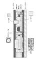
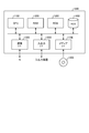
- FIG. 2 shows an example of a slide for imaging.
- FIG. 2 is a vertical view of the slide for imaging.
- the Z direction is the direction of the thickness of the slide.
- the Z direction is the direction of the thickness of the subject.
- the Z direction is the direction perpendicular to the medical image.
- the Z direction is the direction of the optical axis at the time of imaging.
- FIG. 2 shows a case where the subject is placed on a slide glass and covered with a cover glass.
- FIG. 2 shows a case where the subject is a section of tissue.
- FIG. 2 shows a case where a sample such as a lymphocyte or a macrophage contained in a tissue is imaged.
- lymphocytes are thick because they overlap.
- macrophages under the lymphocytes. Since the depth of field to be imaged is shallow, it is not possible to focus on the entire image such as lymphocytes and macrophages.
- information processing by the image processing apparatus 100 will be described as a process for correcting the deterioration of visibility due to digitization.
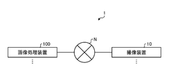
- FIG. 3 is a diagram showing a configuration example of the image processing system according to the embodiment.
- the image processing system 1 includes an image pickup apparatus 10 and an image processing apparatus 100.
- the image pickup apparatus 10 and the image processing apparatus 100 are connected to each other via a predetermined communication network (network N) so as to be communicable by wire or wirelessly.
- FIG. 3 is a diagram showing a configuration example of the image processing system according to the embodiment.
- the image processing system 1 shown in FIG. 3 may include a plurality of image pickup devices 10 and a plurality of image processing devices 100.
- the image pickup device 10 is an image pickup device such as a microscope, and is used for imaging a sample.
- the image processing device 100 is used to determine information about the filter according to the degree of focusing of the subject.
- the image processing device 100 is, for example, an information processing device such as a PC or WS (Work Station), and performs processing based on information transmitted from the image pickup device 10 or the like via the network N.
- the filter according to the embodiment is a filter that improves the image quality of medical images. Further, the filter according to the embodiment is applied to a medical image obtained by capturing a subject. Moreover, any kind of filter according to an embodiment may be used. That is, there is no limitation on the area emphasized by the filter according to the embodiment.
- the filter according to the embodiment includes filters such as high frequency enhancement, mid frequency enhancement, low frequency enhancement, negative enhancement filter, that is, a smoothing filter.
- the image processing device 100 calculates the degree of focusing by using a blur function (hereinafter, appropriately referred to as a “blurring determination function” or a “blurring amount determination function”).
- a blur function hereinafter, appropriately referred to as a “blurring determination function” or a “blurring amount determination function”.
- the blur function is generated by approximating the sum of squares of adjacent differences with the Lorentz function and calculating the reciprocal.
- the approximation according to the embodiment is graph fitting (curve fitting).
- the formula (1) shows the sum of squared adjacent differences according to the embodiment.
- FIG. 4 shows a graph GR1 of the sum of squared adjacent differences.
- the feature amount for all the pixels in the medical image, the total value of the differences between the predetermined pixels and the pixels having a predetermined relationship is used as the feature amount, and the value in the Z direction (hereinafter, appropriately referred to as the “Z value”). ) Is plotted as a variable, and the graph GR1 is shown.
- this feature amount is appropriately referred to as "blurring feature amount”.
- the pixel having a predetermined relationship is a pixel adjacent to the predetermined pixel.
- FIG. 4 shows a graph in which the total value of the differences between the predetermined pixel and the adjacent pixel is plotted for all the pixels in the medical image.
- FIG. 4 shows a graph in which the total value of the differences between the predetermined pixel and the adjacent pixel is plotted for all the pixels in the medical image.
- the horizontal axis (X axis) of the graph GR1 is the Z value of the slide.
- the vertical axis (Y-axis) of the graph GR1 indicates the feature amount.
- the output value of the sum of squares of adjacent differences is shown by s (z).
- plotting is performed so that the Z value at which the feature amount is maximized becomes 0.
- plot so that the maximum value of the output value of the sum of squares of the adjacent differences is s (0).
- FIG. 4 shows that the larger the feature amount, the higher the degree of focusing.
- FIG. 4 may show a graph in which the sum of squares of adjacent differences is approximated by the Lorentz function.
- equation (2) shows the Lorentz function according to the embodiment.
- the Y-axis of the graph GR1 in FIG. 4 may be f (z). That is, the Y-axis of the graph GR1 in FIG. 4 may be indicated by f (z) as the output value of the Lorentz function.
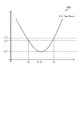
- FIG. 5 shows a graph GR2 which is the reciprocal of the Lorentz function f (z).
- FIG. 5 shows a graph GR2 plotting the reciprocal of the Lorentz function f (z).
- the graph GR2 is a quadratic curve.
- the equation (3) shows a quadratic curve according to the embodiment.
- the apex of the graph GR2 indicates the in-focus position.
- the focusing position according to the embodiment is a Z value that maximizes the degree of focusing.
- the image processing device 100 acquires image information of a predetermined in-focus image.
- the image processing device 100 acquires a predetermined number of image information focused on positions having different Z values based on the predetermined in-focus image together with the predetermined in-focus image.
- the image processing device 100 acquires image information focused at a position several micrometers different in the Z direction with respect to the Z value of a predetermined focused image.
- the image processing apparatus 100 includes a total of two images focused on a predetermined in-focus image and a position several micrometers different in the Z direction with respect to the Z value of the predetermined in-focus image. Acquire information on three images.
- the image processing device 100 calculates the blur feature amount of the acquired image information by using the sum of squares of the adjacent differences. Specifically, the image processing apparatus 100 calculates the blur feature amount of the acquired image information by approximating the sum of squares of the adjacent differences to the Lorentz function.
- the image processing device 100 calculates the reciprocal of the calculated blur feature amount.
- the image processing device 100 performs fitting to a quadratic curve based on the reciprocal of the calculated bokeh feature amount.
- the image processing device 100 estimates the in-focus position based on the fitted quadratic curve. Specifically, the image processing device 100 estimates the apex of the fitted quadratic curve as the focusing position of the entire image.
- the image processing device 100 calculates the degree of focusing of the acquired image information based on the estimated focusing position. Specifically, the image processing device 100 calculates the degree of focusing of the acquired image information based on the difference between the estimated focusing position and the Z value used in the blur function.
- the image processing device 100 determines the strength of the filter according to the calculated degree of focusing.
- the image processing device 100 taps around a predetermined pixel with a predetermined pixel in the medical image as a reference, and calculates a blur feature amount by using the sum of squares of adjacent differences.
- the tap according to the embodiment indicates a pixel range centered on a predetermined pixel. That is, the tap according to the embodiment indicates the range of peripheral pixels of the pixel of interest. For example, the tap according to the embodiment indicates the range of peripheral pixels of the pixel of interest to which the filter is applied. For example, a 3 ⁇ 3 tap indicates a range of 9 pixels in total, in which the vertical and horizontal pixels of the image are 3 pixels each.
- the image processing device 100 taps the same for each of the images acquired with different Z values, and calculates the sum of squares of the adjacent differences as the blur feature amount.
- the image processing device 100 shows an example of attaching a 3 ⁇ 3 tap TA1 as an example.
- the image processing device 100 calculates the blur feature amount centering on S0, with S0 as a predetermined pixel. In this case, the image processing device 100 calculates the blur feature amount based on the equation (4).
- the image processing device 100 acquires a total of three image information of a predetermined in-focus image and two images focused at different positions in the Z direction with respect to the Z value of the predetermined in-focus image. If so, the image processing device 100 calculates the blur feature amount by tapping 3 ⁇ 3 from each of the three images and using the sum of squares of the adjacent differences from the center. In this case, the image processing device 100 calculates the blur feature amount based on the equation (5).
- the image processing device 100 calculates the blur feature amount using the image information of the layer located at the predetermined Z value among the acquired image information. For example, the image processing device 100 calculates the blur feature amount F2 by using the image information of the upper layer among the acquired three image information. For example, the image processing device 100 calculates the blur feature amount F1 by using the image information of the middle layer among the acquired three image information. For example, the image processing device 100 calculates the blur feature amount F0 by using the image information of the lower layer among the acquired three image information.
- FIG. 7 shows a graph GR3 in which the reciprocals of the three values calculated by the image processing device 100 are fitted to a quadratic curve.
- the image processing device 100 estimates the in-focus position based on the fitting.
- the image processing device 100 estimates the apex of the fitted quadratic curve as the in-focus position.
- Zc is the in-focus position.
- Zc is the in-focus position estimated from the blur feature amount.
- Z1 is the most focused position in the entire image.
- Z1 closest to Zc is the most focused position in the entire image.
- the image processing apparatus 100 may apply a filter having a strength equivalent to the result of applying the filter to be applied to Zc to Z1.
- the image processing apparatus 100 may apply a filter having the same strength as Zc to Z1 when Z1 is within a predetermined range considered to be equivalent to Zc.
- the image processing device 100 calculates the degree of focusing according to the distance from the focusing position. In FIG. 7, the image processing device 100 calculates the degree of focusing according to the distance from Zc.
- the image processing device 100 determines the strength of the filter to be applied according to the calculated degree of focusing. Then, the image processing device 100 applies a filter according to the determined intensity. Specifically, the image processing apparatus 100 determines the strength of the filter for each pixel and performs the filter processing on the pixel. As a result, the image processing apparatus 100 performs the most suitable filter processing on the image by repeating the processing for each pixel.
- the image processing device 100 can change the strength of the filter according to the degree of focusing.
- the image processing apparatus 100 can apply a filter having an intensity of 100% only to the in-focus region of the image. Applying a 100% intensity filter to the entire image will increase the sharpness of out-of-focus areas and noise.
- the image processing apparatus 100 applies the filter only to the in-focus region, the sharpness is improved only in the in-focus region. Since the sharpness of the out-of-focus area is not emphasized, the sense of depth of the image does not decrease, and it is easy to recognize the overlap of cells. Since the sharpness of the noise is not emphasized, it is possible to prevent a fine subject such as Helicobacter pylori from being buried in the noise.
- the image processing apparatus 100 can adjust the local contrast.
- the image processing device 100 can correct an image whose contrast has been lowered by the imaging optical system.
- the image processing apparatus 100 can partially adjust the contrast.
- the image processing apparatus 100 can confirm the situation even when mucus or the like is mixed in the cell nucleus and the genetic information is not in the center of the cell nucleus, and the accuracy of diagnosis can be improved.
- the image processing device 100 shows an example of selecting a square tap centered on a predetermined pixel, but the range of the selected tap is not limited to a square such as 3 ⁇ 3, and any range is used. May be selected as a tap.
- the image processing device 100 may select a range of cross-shaped taps centered on S0 as shown in FIG. Further, the number of vertical and horizontal pixels in the selected range is not limited to three pixels.
- the image processing device 100 may select a range of 11 ⁇ 11 with 11 vertical and 11 horizontal pixels as taps.
- the image processing apparatus 100 estimates the in-focus position by using the reciprocal of the three values calculated by using the information of three images having different Z directions. As long as the number of image information to be estimated is 3 or more, there is no limit. For example, the image processing apparatus 100 may estimate the in-focus position by using the reciprocal of four values calculated by using the information of four images having different Z directions.
- the image processing device 100 determines the strength of the filter according to the degree of focusing, but the image processing device 100 may determine the type of the filter according to the degree of focusing. ..
- the image processing apparatus 100 determines the type of filter according to the estimated focusing position.
- the image processing apparatus 100 determines the type of the corresponding specific filter when the degree of focusing satisfies a predetermined condition.
- the image processing apparatus 100 determines the type of filter that emphasizes the corresponding predetermined region when the degree of focusing satisfies a predetermined condition.
- the image processing apparatus 100 determines that the mid-range enhancement filter is applied when the degree of focusing is equal to or higher than a predetermined threshold value. For example, the image processing apparatus 100 determines that the high frequency enhancement filter is applied when the degree of focusing is smaller than a predetermined threshold value. Alternatively, the image processing apparatus 100 determines to apply a negative enhancement filter, that is, a smoothing filter.
- the image processing device 100 may determine the strength and type of the filter according to the degree of focusing.
- the image processing apparatus 100 may simultaneously determine both the strength and the type of the filter according to the degree of focusing.
- the image processing apparatus 100 may apply the determined intensity and type of filter to the medical image.
- the image processing apparatus 100 can apply the optimum filter with the optimum intensity according to the degree of focusing.
- the image processing device 100 determines the strength and type of the filter for each pixel. However, the image processing device 100 constitutes a block with a plurality of pixels and the strength of the filter for each block. And the type may be determined. In this case, the image processing apparatus 100 determines a plurality of pixels for forming the block. The image processing apparatus 100 may determine a plurality of pixels for forming the block. For example, the image processing device 100 constitutes a block with a plurality of adjacent pixels. For example, the image processing device 100 constitutes a block with a plurality of predetermined pixels.
- the image processing apparatus 100 acquires a medical image with a sample such as a cell as a subject, but an image of a living thing or any image collected from the living thing is used as a subject. You may get it.
- the image processing device 100 acquires an image of a sample related to a living body, a living thing, a material, a pathology, or the like in the medical field.
- the imaging device according to the embodiment may be any device as long as it can image a subject.
- the imaging device according to the embodiment is a microscope.
- any microscope may be used.
- the image processing apparatus 100 estimates the apex of the fitted quadratic curve as the focusing position of the entire image, but it is within a predetermined range from the apex of the fitted quadratic curve.
- the position may be estimated as the in-focus position of the entire image.
- the pixel having a predetermined relationship is a pixel adjacent to the predetermined pixel, but the present invention is not limited to this example. That is, the pixels having a predetermined relationship are not necessarily limited to adjacent pixels.
- the pixels having a predetermined relationship may be pixels such as every other pixel or every two pixels.
- the image processing apparatus 100 may calculate the degree of focusing by using the total value of the differences between the predetermined pixels and the pixels of every other pixel as the feature amount. In this case, the image processing apparatus 100 determines the intensity of the filter applied to the medical image according to the degree of focusing calculated by using the total value of the differences between the predetermined pixels and the pixels of every other pixel as the feature amount.
- the image pickup device 10 and the image processing device 100 are separate devices, but the image pickup device 10 and the image processing device 100 may be integrated.
- the function of the image processing device 100 may be mounted on a computer that controls the operation of the image pickup device 10, or may be mounted on an arbitrary computer provided in the housing of the image pickup device 10.
- the function of the image processing device 100 may be downloaded to a computer that controls the operation of the image pickup device 10, or may be downloaded to an arbitrary computer provided in the housing of the image pickup device 10. Thereby, the image pickup apparatus 10 having the function of the image processing apparatus 100 can be sold.
- FIG. 9 is a diagram showing a configuration example of the image pickup apparatus 10 according to the embodiment.
- the image pickup apparatus 10 includes a communication unit 11, a storage unit 12, and a control unit 13.
- the image pickup device 10 has an input unit (for example, a keyboard, a mouse, etc.) that receives various operations from the administrator of the image pickup device 10, and a display unit (for example, a liquid crystal display, etc.) for displaying various information. May be good.
- the communication unit 11 is realized by, for example, a NIC (Network Interface Card) or the like. Then, the communication unit 11 is connected to the predetermined network N by wire or wirelessly, and transmits / receives information to / from the image processing device 100 or the like via the predetermined network N.
- NIC Network Interface Card
- the storage unit 12 is realized by, for example, a semiconductor memory element such as a RAM or a flash memory, or a storage device such as a hard disk or an optical disk.
- the storage unit 12 stores information about the medical image. Specifically, the storage unit 12 stores information about the medical image of the captured subject.
- the control unit 13 is a controller, and is realized by, for example, a CPU, an MPU, or the like executing various programs stored in a storage device inside the image pickup device 10 using the RAM as a work area. Further, the control unit 13 is a controller, and is realized by, for example, an integrated circuit such as an ASIC or FPGA.
- control unit 13 has an imaging unit 141, and realizes or executes the action of information processing described below.
- the internal configuration of the control unit 13 is not limited to the configuration shown in FIG. 9, and may be any other configuration as long as it is a configuration for performing information processing described later.
- the image pickup unit 141 captures various information.
- the imaging unit 141 images the subject on the slide.
- the imaging unit 141 acquires various information.
- the imaging unit 141 acquires the captured medical image.
- FIG. 10 is a diagram showing a configuration example of the image processing device 100 according to the embodiment.
- the image processing device 100 includes a communication unit 110, a storage unit 120, and a control unit 130.
- the image processing device 100 has an input unit (for example, a keyboard, a mouse, etc.) that receives various operations from the administrator of the image processing device 100, and a display unit (for example, a liquid crystal display, etc.) for displaying various information. You may.
- the communication unit 110 is realized by, for example, a NIC or the like. Then, the communication unit 110 is connected to the network N by wire or wirelessly, and transmits / receives information to / from the image pickup apparatus 10 and the like via the network N.
- the storage unit 120 is realized by, for example, a semiconductor memory element such as a RAM or a flash memory, or a storage device such as a hard disk or an optical disk. As shown in FIG. 10, the storage unit 120 includes a medical image storage unit 121 and an emphasis filter storage unit 122.
- the medical image storage unit 121 stores information related to medical images.
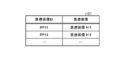
- FIG. 11 shows an example of the medical image storage unit 121 according to the embodiment.
- the medical image storage unit 121 has items such as “medical image ID” and “medical image”.
- Medical image ID indicates identification information for identifying a medical image.
- the “medical image” indicates a medical image obtained by capturing an image of a subject.
- “medical image” indicates a medical image captured by the imaging device 10.
- the “medical image” shows an example in which conceptual information such as “medical image # 11" and “medical image # 12" is stored, but in reality, a still image, a moving image, or the like is shown. Is stored.
- still images and moving images are stored in a server or cloud different from the image processing device, and the "medical image” indicates the URL (Uniform Resource Locator) where the contents of the medical image are located or their storage location.
- the file path name and the like may be stored.
- the emphasis filter storage unit 122 stores information about an emphasis filter for applying to a medical image.
- FIG. 12 shows an example of the emphasis filter storage unit 122 according to the embodiment.
- the emphasis filter storage unit 122 has items such as “emphasis filter ID” and “emphasis filter”.
- Emphasis filter ID indicates identification information for identifying the emphasis filter.
- “Emphasis filter” indicates information about the emphasis filter. In the example shown in FIG. 12, an example in which conceptual information such as “emphasis filter # 11" and “emphasis filter # 12" is stored in the “emphasis filter” is shown, but in reality, the strength and type of the emphasis filter are used. , The range of pixels to which the emphasis filter is applied, etc. are stored.
- the control unit 130 is a controller, and is realized by, for example, a CPU, an MPU, or the like executing various programs stored in a storage device inside the image processing device 100 using the RAM as a work area. Further, the control unit 130 is a controller, and is realized by, for example, an integrated circuit such as an ASIC or FPGA.
- control unit 130 has an acquisition unit 131, a calculation unit 132, and a determination unit 133, and realizes or executes the information processing operation described below.
- the internal configuration of the control unit 130 is not limited to the configuration shown in FIG. 10, and may be another configuration as long as it is a configuration for performing information processing described later.
- the acquisition unit 131 acquires various types of information.
- the acquisition unit 131 acquires various information from an external information processing device.
- the acquisition unit 131 acquires various information from other information processing devices such as the image pickup device 10.
- the acquisition unit 131 acquires various information from the storage unit 120.
- the acquisition unit 131 acquires various information from the medical image storage unit 121 and the emphasis filter storage unit 122.
- the acquisition unit 131 stores various acquired information in the storage unit 120.
- the acquisition unit 131 stores various information in the medical image storage unit 121 and the emphasis filter storage unit 122.
- the acquisition unit 131 acquires various information calculated and determined by other functional configurations.
- the acquisition unit 131 acquires a medical image of the subject.
- the acquisition unit 131 acquires a medical image of the subject captured by the imaging device 10.
- the acquisition unit 131 acquires a medical image of a subject related to a living body, an organism, a material, or a pathology in the medical field.
- the acquisition unit 131 acquires a medical image captured by a microscope.
- the calculation unit 132 calculates various types of information.
- the calculation unit 132 calculates various information from the storage unit 120.
- the calculation unit 132 calculates various information from the medical image storage unit 121 and the emphasis filter storage unit 122.
- the calculation unit 132 stores various calculated information in the storage unit 120.
- the calculation unit 132 stores various information in the medical image storage unit 121 and the emphasis filter storage unit 122.
- the calculation unit 132 calculates various information acquired and determined by other functional configurations.
- the calculation unit 132 calculates various information based on various information acquired and determined by other functional configurations.
- the calculation unit 132 calculates the sum of squares of the adjacent differences using the acquired image information.
- the calculation unit 132 calculates the sum of squares of adjacent differences within the range of taps determined centering on a predetermined pixel. For example, the calculation unit 132 calculates the sum of squares of the adjacent differences based on the feature amount obtained by summing the differences between the predetermined pixels and the adjacent pixels in the medical image.
- the calculation unit 132 calculates the Lorentz function from the calculated sum of squares of the adjacent differences.
- the calculation unit 132 calculates an approximate value of the Lorentz function from the calculated sum of squares of the adjacent differences.
- the calculation unit 132 approximates the calculated contiguous difference squared sum to the Lorentz function.
- the calculation unit 132 calculates the reciprocal of the Lorentz function from the calculated Lorentz function.
- the calculation unit 132 estimates the focusing position from the reciprocal of the Lorentz function.
- the calculation unit 132 estimates the apex of the reciprocal of the Lorentz function as the in-focus position.
- the calculation unit 132 calculates the degree of focusing.
- the calculation unit 132 calculates the degree of focusing using the estimated focusing position.
- the calculation unit 132 calculates the degree of focusing according to the distance from the estimated focusing position.
- the calculation unit 132 calculates the degree of focusing according to the distance between the Z value corresponding to the reciprocal of the calculated Lorentz function and the estimated focusing position.
- the determination unit 133 determines various information.
- the determination unit 133 determines various information from the storage unit 120.
- the determination unit 133 determines various information from the medical image storage unit 121 and the emphasis filter storage unit 122.
- the determination unit 133 stores various determined information in the storage unit 120.
- the determination unit 133 stores various information in the medical image storage unit 121 and the emphasis filter storage unit 122.
- the determination unit 133 determines various information acquired and calculated by other functional configurations.
- the determination unit 133 determines various information based on various information acquired and calculated by other functional configurations.
- the determination unit 133 selects the pixel to which the filter is applied.
- the determination unit 133 selects the first pixel to which the filter is applied. For example, the determination unit 133 selects the next pixel after application in which a filter is applied to a predetermined pixel. For example, the determination unit 133 selects the pixels to which the filter is applied based on a predetermined algorithm.
- the determination unit 133 determines the intensity of the filter applied to the medical image according to the calculated degree of focusing.
- the determination unit 133 determines a synthesis rate indicating the rate of synthesis of medical images according to a plurality of filters having different intensities according to the calculated degree of focusing.
- the determination unit 133 selectively determines a plurality of filters to be applied to the medical image according to the calculated degree of focusing.
- the determination unit 133 determines the type of filter applied to the medical image according to the calculated degree of focusing.
- the determination unit 133 determines a synthesis rate indicating the rate of synthesis of medical images according to a plurality of different types of filters according to the calculated degree of focusing.
- the determination unit 133 applies the determined intensity filter to the medical image.
- the determination unit 133 applies the determined type of filter to the medical image.
- the determination unit 133 applies a filter of the intensity determined for a plurality of medical images having different Z values to each medical image according to the calculated degree of focusing. Then, the determination unit 133 determines the synthesis rate indicating the synthesis rate of each medical image to which the filter is applied according to the calculated degree of focusing. Then, the determination unit 133 synthesizes each medical image based on the synthesis rate determined according to the calculated degree of focusing.
- the determination unit 133 determines whether or not the filter has been applied to all the pixels. The determination unit 133 determines whether all the pixels in the medical image have been filtered. The determination unit 133 determines whether all the pixels included in the predetermined range in the medical image have been filtered.
- FIG. 13 is a flowchart showing a procedure of information processing by the image processing system 1 according to the embodiment.
- the image processing device 100 acquires a medical image (step S101).
- the image processing device 100 selects a predetermined pixel for performing the filtering process (step S102).
- the image processing device 100 estimates the degree of focusing using a blur function (step S103).
- the image processing apparatus 100 determines the type and intensity of the filter from the estimated degree of focusing (step S104).
- the image processing apparatus 100 applies a filter of the determined type and intensity (step S105).
- the image processing device 100 determines whether all the pixels have been filtered (step S106). When the image processing apparatus 100 determines that the filtering processing has not been performed on all the pixels (step S106; No), the image processing apparatus 100 returns to the processing of step S102.
- the image processing apparatus 100 returns to the process of step S102 and selects pixels other than the previously selected pixel.
- the image processing device 100 ends the information processing.
- FIG. 14 shows a case where the image processing device 100 applies one enhancement filter to the acquired medical image.
- the image KG1 shows the image before applying the filter
- the image KG2 shows the image after applying the filter.
- an image with improved contrast and resolution of the entire image is generated, including an object other than the object to be focused on.
- the image processing device 100 may apply a plurality of enhancement filters to the acquired medical image.
- the image processing device 100 may generate a composite image to which a plurality of filters having different intensities depending on the degree of focusing are applied.
- FIG. 15 shows a case where the image processing device 100 synthesizes an image to which a plurality of enhancement filters are applied to the acquired medical image.
- the image KG11 shows an image to which the first filter is applied
- the image KG22 shows an image to which a second filter having a different intensity from that of the first filter is applied.
- the image KG11 is a more blurred image than the image KG22.
- the image KG33 shows a composite image in which the image KG11 and the image KG22 are combined.
- the target SJ 11 shows a first region showing a region of interest in an image
- the target SJ 22 shows a second region that is not a region of interest.
- the target SJ22 is a noise portion in a medical image.
- the image processing device 100 may determine a composition rate indicating the rate of composition of medical images. For example, the image processing apparatus 100 may determine the composition rate in the first region and the second region.
- the image processing apparatus 100 synthesizes the image KG11 and the image KG22 at a composition ratio of 1: 9 with respect to the region of the target SJ11.
- the ratio of the synthesis ratio to the region of the target SJ11 may be any ratio as long as the image KG22 has a higher ratio than the image KG11.
- the image processing apparatus 100 synthesizes the image KG11 and the image KG22 at a composition ratio of 9: 1 with respect to the region of the target SJ22.
- the ratio of the synthesis ratio to the region of the target SJ22 may be any ratio as long as the image KG11 has a higher ratio than the image KG22.
- FIG. 15 shows a case where two images to which the enhancement filter is applied are combined, but it is assumed that there is no limit to the number of images to be combined by the image processing device 100.
- the image processing apparatus 100 may selectively determine the number of images to be combined, or may selectively determine the images to be combined. For example, the image processing apparatus 100 selectively combines a plurality of images to which another filter is applied and an image to which the first filter is applied when there is a region that cannot be discriminated by the image to which the first filter is applied. Generates an image with improved visibility and distinctiveness as compared with an image to which only the first filter is applied.
- the image processing device 100 can adjust the local contrast by synthesizing the processed images of the enhancement filters having different intensities.
- the image processing apparatus 100 can adjust the global and local contrasts by adaptively applying the optimum filter, and can improve the visibility like an optical microscope.
- FIG. 15 shows an example of synthesizing an image in which a plurality of different filters are applied to one image.
- the image processing device 100 may generate a composite image by synthesizing an image to which a plurality of different filters are applied to one image.
- the image processing apparatus 100 applies an optimum filter according to the degree of focusing to a plurality of medical images having different Z values according to the degree of focusing.
- a composite image may be generated by synthesizing the images.
- FIG. 16 is a hardware configuration diagram showing an example of a computer that realizes the functions of the image pickup apparatus 10 and the image processing apparatus 100.
- the computer 1000 has a CPU 1100, a RAM 1200, a ROM 1300, an HDD 1400, a communication interface (I / F) 1500, an input / output interface (I / F) 1600, and a media interface (I / F) 1700.
- the CPU 1100 operates based on the program stored in the ROM 1300 or the HDD 1400, and controls each part.
- the ROM 1300 stores a boot program executed by the CPU 1100 when the computer 1000 is started, a program depending on the hardware of the computer 1000, and the like.
- the HDD 1400 stores a program executed by the CPU 1100, data used by such a program, and the like.
- the communication interface 1500 receives data from another device via a predetermined communication network and sends it to the CPU 1100, and transmits the data generated by the CPU 1100 to the other device via the predetermined communication network.
- the CPU 1100 controls an output device such as a display or a printer and an input device such as a keyboard or a mouse via the input / output interface 1600.
- the CPU 1100 acquires data from the input device via the input / output interface 1600. Further, the CPU 1100 outputs the generated data to the output device via the input / output interface 1600.
- the media interface 1700 reads the program or data stored in the recording medium 1800 and provides the program or data to the CPU 1100 via the RAM 1200.
- the CPU 1100 loads the program from the recording medium 1800 onto the RAM 1200 via the media interface 1700, and executes the loaded program.
- the recording medium 1800 is, for example, an optical recording medium such as a DVD (Digital Versatile Disc) or PD (Phase change rewritable disk), a magneto-optical recording medium such as an MO (Magneto-Optical disk), a tape medium, a magnetic recording medium, or a semiconductor memory. And so on.
- the CPU 1100 of the computer 1000 realizes the functions of the control units 13 and 130 by executing the program loaded on the RAM 1200. To do.
- the CPU 1100 of the computer 1000 reads these programs from the recording medium 1800 and executes them, but as another example, these programs may be acquired from another device via a predetermined communication network.
- each component of each device shown in the figure is a functional concept, and does not necessarily have to be physically configured as shown in the figure. That is, the specific form of distribution / integration of each device is not limited to the one shown in the figure, and all or part of the device is functionally or physically distributed / physically in arbitrary units according to various loads and usage conditions. Can be integrated and configured.
- section, module, unit can be read as “means” or “circuit”.
- acquisition unit can be read as an acquisition means or an acquisition circuit.
- the present technology can also have the following configurations.
- the computer acquires the medical image captured by the imaging device and An image processing method for determining the intensity of a filter applied to the medical image according to the degree of focusing of the medical image.
- the image processing method according to (1) wherein the intensity of the filter applied to the medical image is determined according to the degree of focusing calculated by the blur function indicating the degree of blur of the medical image.
- the strength of the filter applied to the medical image is determined according to the degree of focusing calculated by the blur function in the direction perpendicular to the medical image and in the direction of the thickness of the subject (1).
- the image processing method according to (2) is Alternatively, the image processing method according to (2).
- the strength of the filter applied to the medical image is determined according to the degree of focusing calculated from the feature amount obtained by summing the differences between the predetermined pixel and the peripheral pixels in the medical image (1).
- the image processing method according to any one of (3).
- (5) Based on the estimated degree of focusing estimated based on the blur function and the degree of focusing calculated by the feature amount obtained by summing the difference between a predetermined pixel and peripheral pixels in the medical image.
- the image processing method according to any one of (1) to (4) which determines the strength of the filter applied to the medical image.
- Any one of (1) to (5) determines the composition rate indicating the composition rate of the composite image generated by applying a plurality of different filters to the medical image according to the degree of focusing of the subject.
- the image processing method described in the section. (7) The image processing method according to any one of (1) to (6), wherein the composite rate of the composite image generated by applying a plurality of filters having different intensities to the predetermined medical image is determined. (8) Any of (1) to (7), which determines the composition rate of the composite image generated by applying a filter according to the degree of focusing of the subject to the plurality of medical images having different Z values.
- the image processing method according to item 1. (9) The item according to any one of (1) to (8), wherein the plurality of filters to be applied to the medical image for generating the composite image are selectively determined according to the degree of focusing of the subject. Image processing method.
- High-frequency enhancement, mid-frequency enhancement, low-frequency enhancement, or negative enhancement filter, that is, smoothing filter is determined as the type of region emphasized by the filter according to the degree of focusing of the subject (1) to (9).
- An acquisition unit that acquires a medical image of the subject captured by a microscope, A filter applied to the medical image according to the degree of focusing of the subject, and a determination unit for determining the strength of the filter for improving the image quality of the medical image.
- An image processing device comprising. (14) An imaging device that captures the subject and An image processing system including software used for processing a medical image corresponding to an object imaged by the image pickup apparatus. The software includes an image processing device that determines the intensity of a filter applied to a medical image captured by the imaging device according to the degree of focusing of the subject. Image processing system including.
- Image processing system 10 Image processing device 100 Image processing device 110 Communication unit 120 Storage unit 121 Medical image storage unit 122 Emphasis filter storage unit 130 Control unit 131 Acquisition unit 132 Calculation unit 133 Decision unit N network
Landscapes
- Engineering & Computer Science (AREA)
- Physics & Mathematics (AREA)
- General Physics & Mathematics (AREA)
- Theoretical Computer Science (AREA)
- Multimedia (AREA)
- Computer Vision & Pattern Recognition (AREA)
- Optics & Photonics (AREA)
- Analytical Chemistry (AREA)
- Chemical & Material Sciences (AREA)
- Health & Medical Sciences (AREA)
- General Health & Medical Sciences (AREA)
- Medical Informatics (AREA)
- Nuclear Medicine, Radiotherapy & Molecular Imaging (AREA)
- Radiology & Medical Imaging (AREA)
- Quality & Reliability (AREA)
- Image Processing (AREA)
Abstract
Dans un procédé de traitement d'images selon la présente invention, une image médicale capturée par un dispositif de capture d'image est acquise et l'intensité d'un filtre appliqué à l'image médicale est déterminée en fonction du degré de focalisation de l'image médicale.
Priority Applications (4)
| Application Number | Priority Date | Filing Date | Title |
|---|---|---|---|
| CN202080079048.XA CN114730070A (zh) | 2019-11-22 | 2020-09-30 | 图像处理方法、图像处理装置和图像处理系统 |
| US17/776,985 US20220392031A1 (en) | 2019-11-22 | 2020-09-30 | Image processing method, image processing apparatus and image processing system |
| JP2021558198A JPWO2021100328A1 (fr) | 2019-11-22 | 2020-09-30 | |
| EP20890703.0A EP4047408A4 (fr) | 2019-11-22 | 2020-09-30 | Procédé, dispositif et système de traitement d'images |
Applications Claiming Priority (2)
| Application Number | Priority Date | Filing Date | Title |
|---|---|---|---|
| JP2019211390 | 2019-11-22 | ||
| JP2019-211390 | 2019-11-22 |
Publications (1)
| Publication Number | Publication Date |
|---|---|
| WO2021100328A1 true WO2021100328A1 (fr) | 2021-05-27 |
Family
ID=75980520
Family Applications (1)
| Application Number | Title | Priority Date | Filing Date |
|---|---|---|---|
| PCT/JP2020/037068 WO2021100328A1 (fr) | 2019-11-22 | 2020-09-30 | Procédé, dispositif et système de traitement d'images |
Country Status (5)
| Country | Link |
|---|---|
| US (1) | US20220392031A1 (fr) |
| EP (1) | EP4047408A4 (fr) |
| JP (1) | JPWO2021100328A1 (fr) |
| CN (1) | CN114730070A (fr) |
| WO (1) | WO2021100328A1 (fr) |
Families Citing this family (1)
| Publication number | Priority date | Publication date | Assignee | Title |
|---|---|---|---|---|
| JP7280107B2 (ja) * | 2019-05-10 | 2023-05-23 | 株式会社エビデント | 画像処理方法、プログラム、画像処理装置、画像処理システム、及び、顕微鏡システム |
Citations (7)
| Publication number | Priority date | Publication date | Assignee | Title |
|---|---|---|---|---|
| JPS5994712A (ja) * | 1982-11-22 | 1984-05-31 | Olympus Optical Co Ltd | 合焦検出方法 |
| JPH10243289A (ja) * | 1997-02-27 | 1998-09-11 | Olympus Optical Co Ltd | 画像加算装置 |
| JP2011090221A (ja) * | 2009-10-23 | 2011-05-06 | Sony Corp | 顕微鏡、合焦位置検出方法及び合焦位置検出プログラム |
| JP2011197283A (ja) | 2010-03-18 | 2011-10-06 | Sony Corp | 合焦装置、合焦方法、合焦プログラム及び顕微鏡 |
| JP2017158764A (ja) * | 2016-03-09 | 2017-09-14 | ソニー株式会社 | 画像処理装置、画像処理方法、及び記録媒体 |
| JP2019114250A (ja) * | 2017-12-21 | 2019-07-11 | 株式会社ニコン | 画像処理装置、画像処理プログラム、画像処理方法および撮像装置 |
| JP2019149719A (ja) * | 2018-02-27 | 2019-09-05 | キヤノン株式会社 | 画像処理装置及び方法、及び撮像装置 |
Family Cites Families (9)
| Publication number | Priority date | Publication date | Assignee | Title |
|---|---|---|---|---|
| JP5657375B2 (ja) * | 2010-12-24 | 2015-01-21 | オリンパス株式会社 | 内視鏡装置及びプログラム |
| JP5705096B2 (ja) * | 2011-12-02 | 2015-04-22 | キヤノン株式会社 | 画像処理装置及び画像処理方法 |
| US8994809B2 (en) * | 2012-07-19 | 2015-03-31 | Sony Corporation | Method and apparatus for simulating depth of field (DOF) in microscopy |
| US8928772B2 (en) * | 2012-09-21 | 2015-01-06 | Eastman Kodak Company | Controlling the sharpness of a digital image |
| JP2014071207A (ja) * | 2012-09-28 | 2014-04-21 | Canon Inc | 画像処理装置、撮像システム、画像処理システム |
| US9897792B2 (en) * | 2012-11-30 | 2018-02-20 | L&T Technology Services Limited | Method and system for extended depth of field calculation for microscopic images |
| US10678041B2 (en) * | 2013-03-13 | 2020-06-09 | Sony Corporation | Information processing apparatus, information processing method, and information processing program |
| US10419698B2 (en) * | 2015-11-12 | 2019-09-17 | Canon Kabushiki Kaisha | Image processing apparatus and image processing method |
| CN108700733A (zh) * | 2016-02-22 | 2018-10-23 | 皇家飞利浦有限公司 | 用于生成生物样本的具有增强景深的合成2d图像的系统 |
-
2020
- 2020-09-30 CN CN202080079048.XA patent/CN114730070A/zh active Pending
- 2020-09-30 US US17/776,985 patent/US20220392031A1/en active Pending
- 2020-09-30 JP JP2021558198A patent/JPWO2021100328A1/ja active Pending
- 2020-09-30 EP EP20890703.0A patent/EP4047408A4/fr active Pending
- 2020-09-30 WO PCT/JP2020/037068 patent/WO2021100328A1/fr unknown
Patent Citations (7)
| Publication number | Priority date | Publication date | Assignee | Title |
|---|---|---|---|---|
| JPS5994712A (ja) * | 1982-11-22 | 1984-05-31 | Olympus Optical Co Ltd | 合焦検出方法 |
| JPH10243289A (ja) * | 1997-02-27 | 1998-09-11 | Olympus Optical Co Ltd | 画像加算装置 |
| JP2011090221A (ja) * | 2009-10-23 | 2011-05-06 | Sony Corp | 顕微鏡、合焦位置検出方法及び合焦位置検出プログラム |
| JP2011197283A (ja) | 2010-03-18 | 2011-10-06 | Sony Corp | 合焦装置、合焦方法、合焦プログラム及び顕微鏡 |
| JP2017158764A (ja) * | 2016-03-09 | 2017-09-14 | ソニー株式会社 | 画像処理装置、画像処理方法、及び記録媒体 |
| JP2019114250A (ja) * | 2017-12-21 | 2019-07-11 | 株式会社ニコン | 画像処理装置、画像処理プログラム、画像処理方法および撮像装置 |
| JP2019149719A (ja) * | 2018-02-27 | 2019-09-05 | キヤノン株式会社 | 画像処理装置及び方法、及び撮像装置 |
Non-Patent Citations (1)
| Title |
|---|
| See also references of EP4047408A4 |
Also Published As
| Publication number | Publication date |
|---|---|
| EP4047408A4 (fr) | 2022-12-28 |
| US20220392031A1 (en) | 2022-12-08 |
| CN114730070A (zh) | 2022-07-08 |
| JPWO2021100328A1 (fr) | 2021-05-27 |
| EP4047408A1 (fr) | 2022-08-24 |
Similar Documents
| Publication | Publication Date | Title |
|---|---|---|
| US9332190B2 (en) | Image processing apparatus and image processing method | |
| US9881373B2 (en) | Image generating apparatus and image generating method | |
| JP5780865B2 (ja) | 画像処理装置、撮像システム、画像処理システム | |
| US8265362B2 (en) | Pathological tissue image capturing system, method, and program | |
| JP5254441B2 (ja) | フロー式粒子画像解析方法及び装置 | |
| KR101891364B1 (ko) | 현미경 이미징에서의 빠른 오토-포커스 | |
| RU2734447C2 (ru) | Система для формирования синтезированного двухмерного изображения биологического образца с повышенной глубиной резкости | |
| US20150279033A1 (en) | Image data generating apparatus and image data generating method | |
| CN109001902B (zh) | 基于图像融合的显微镜聚焦方法 | |
| JP2015108837A (ja) | 画像処理装置及び画像処理方法 | |
| JP6362062B2 (ja) | 画像生成装置および画像生成方法 | |
| WO2021100328A1 (fr) | Procédé, dispositif et système de traitement d'images | |
| JP2015057682A (ja) | 画像生成装置および画像生成方法 | |
| JP2012255808A (ja) | 病理組織画像撮影システム、病理組織画像撮影方法、および病理組織画像撮影プログラム | |
| Jiang et al. | Blind deblurring for microscopic pathology images using deep learning networks | |
| JP7030986B2 (ja) | 画像生成装置、画像生成方法および画像生成プログラム | |
| US11050931B2 (en) | Control device and control method | |
| CN117474777A (zh) | 一种面向手术显微镜的图像融合方法 | |
| JP2015191362A (ja) | 画像データ生成装置および画像データ生成方法 | |
| Garud et al. | Volume visualization approach for depth-of-field extension in digital pathology | |
| JP2023542619A (ja) | 試料のデジタル画像の品質管理のためのコンピュータ実装方法 | |
| JP2023033982A (ja) | 画像処理装置、画像処理システム、画像の鮮鋭化方法、及び、プログラム | |
| Tadrous | A method of PSF generation for 3D brightfield deconvolution | |
| JP5648366B2 (ja) | 顕微鏡制御装置及び領域判定方法 | |
| CN103487928A (zh) | 散焦量估计方法、成像装置和透明部件 |
Legal Events
| Date | Code | Title | Description |
|---|---|---|---|
| 121 | Ep: the epo has been informed by wipo that ep was designated in this application |
Ref document number: 20890703 Country of ref document: EP Kind code of ref document: A1 |
|
| ENP | Entry into the national phase |
Ref document number: 2021558198 Country of ref document: JP Kind code of ref document: A |
|
| ENP | Entry into the national phase |
Ref document number: 2020890703 Country of ref document: EP Effective date: 20220517 |
|
| NENP | Non-entry into the national phase |
Ref country code: DE |