WO2021100098A1 - 換気装置 - Google Patents
換気装置 Download PDFInfo
- Publication number
- WO2021100098A1 WO2021100098A1 PCT/JP2019/045146 JP2019045146W WO2021100098A1 WO 2021100098 A1 WO2021100098 A1 WO 2021100098A1 JP 2019045146 W JP2019045146 W JP 2019045146W WO 2021100098 A1 WO2021100098 A1 WO 2021100098A1
- Authority
- WO
- WIPO (PCT)
- Prior art keywords
- flow path
- room
- air
- ventilation
- unit
- Prior art date
- Legal status (The legal status is an assumption and is not a legal conclusion. Google has not performed a legal analysis and makes no representation as to the accuracy of the status listed.)
- Ceased
Links
Images






Classifications
-
- F—MECHANICAL ENGINEERING; LIGHTING; HEATING; WEAPONS; BLASTING
- F24—HEATING; RANGES; VENTILATING
- F24F—AIR-CONDITIONING; AIR-HUMIDIFICATION; VENTILATION; USE OF AIR CURRENTS FOR SCREENING
- F24F11/00—Control or safety arrangements
- F24F11/70—Control systems characterised by their outputs; Constructional details thereof
- F24F11/72—Control systems characterised by their outputs; Constructional details thereof for controlling the supply of treated air, e.g. its pressure
- F24F11/74—Control systems characterised by their outputs; Constructional details thereof for controlling the supply of treated air, e.g. its pressure for controlling air flow rate or air velocity
- F24F11/77—Control systems characterised by their outputs; Constructional details thereof for controlling the supply of treated air, e.g. its pressure for controlling air flow rate or air velocity by controlling the speed of ventilators
-
- F—MECHANICAL ENGINEERING; LIGHTING; HEATING; WEAPONS; BLASTING
- F24—HEATING; RANGES; VENTILATING
- F24F—AIR-CONDITIONING; AIR-HUMIDIFICATION; VENTILATION; USE OF AIR CURRENTS FOR SCREENING
- F24F7/00—Ventilation
- F24F7/007—Ventilation with forced flow
-
- F—MECHANICAL ENGINEERING; LIGHTING; HEATING; WEAPONS; BLASTING
- F24—HEATING; RANGES; VENTILATING
- F24F—AIR-CONDITIONING; AIR-HUMIDIFICATION; VENTILATION; USE OF AIR CURRENTS FOR SCREENING
- F24F7/00—Ventilation
- F24F7/04—Ventilation with ducting systems, e.g. by double walls; with natural circulation
- F24F7/06—Ventilation with ducting systems, e.g. by double walls; with natural circulation with forced air circulation, e.g. by fan positioning of a ventilator in or against a conduit
- F24F7/08—Ventilation with ducting systems, e.g. by double walls; with natural circulation with forced air circulation, e.g. by fan positioning of a ventilator in or against a conduit with separate ducts for supplied and exhausted air with provisions for reversal of the input and output systems
-
- F—MECHANICAL ENGINEERING; LIGHTING; HEATING; WEAPONS; BLASTING
- F24—HEATING; RANGES; VENTILATING
- F24F—AIR-CONDITIONING; AIR-HUMIDIFICATION; VENTILATION; USE OF AIR CURRENTS FOR SCREENING
- F24F2110/00—Control inputs relating to air properties
- F24F2110/50—Air quality properties
- F24F2110/65—Concentration of specific substances or contaminants
- F24F2110/70—Carbon dioxide
-
- F—MECHANICAL ENGINEERING; LIGHTING; HEATING; WEAPONS; BLASTING
- F24—HEATING; RANGES; VENTILATING
- F24F—AIR-CONDITIONING; AIR-HUMIDIFICATION; VENTILATION; USE OF AIR CURRENTS FOR SCREENING
- F24F2140/00—Control inputs relating to system states
-
- Y—GENERAL TAGGING OF NEW TECHNOLOGICAL DEVELOPMENTS; GENERAL TAGGING OF CROSS-SECTIONAL TECHNOLOGIES SPANNING OVER SEVERAL SECTIONS OF THE IPC; TECHNICAL SUBJECTS COVERED BY FORMER USPC CROSS-REFERENCE ART COLLECTIONS [XRACs] AND DIGESTS
- Y02—TECHNOLOGIES OR APPLICATIONS FOR MITIGATION OR ADAPTATION AGAINST CLIMATE CHANGE
- Y02B—CLIMATE CHANGE MITIGATION TECHNOLOGIES RELATED TO BUILDINGS, e.g. HOUSING, HOUSE APPLIANCES OR RELATED END-USER APPLICATIONS
- Y02B30/00—Energy efficient heating, ventilation or air conditioning [HVAC]
- Y02B30/70—Efficient control or regulation technologies, e.g. for control of refrigerant flow, motor or heating
Definitions
- the present invention relates to a ventilation device that exchanges outside air with room air.
- the actual operating condition of an air conditioner in an office is that the maximum load factor is around 50% and the most frequent load factor is around 30%. If a model with a larger capacity than the current one is selected to satisfy the WELL standard, the most frequent load factor will be even lower.
- the compressor starts and stops for a longer period of time, so that the compressor operates for a longer time in a region where energy efficiency is low, and there is a problem that power consumption increases.
- An object of the present invention is to provide a ventilation device capable of providing an air volume satisfying the WELL standard and also having a function of a circulator.
- the present invention relates to a ventilation device including an air supply flow path for outside air supplied to a room and an exhaust flow path for exhaust gas discharged from the room.
- the ventilator of the present invention A total heat exchanger through which the outside air in the air supply flow path and the exhaust gas in the exhaust flow path pass.
- the circulation mode in which the supply of the outside air by the air supply flow path is cut off, the exhaust of the exhaust gas by the exhaust flow path is cut off, and the air supply flow path and the exhaust flow path are communicated with each other, and the circulation mode are released. In this mode, the outside air is supplied from the air supply flow path to the room, the exhaust gas is discharged from the exhaust flow path, and the communication between the air supply flow path and the exhaust flow path is cut off.
- a damper mechanism that switches to the release mode which is With The circulation operation in which the air in the room circulates Executed in the circulation mode, the air in the room circulates in the exhaust flow path, the air supply flow path, and the room without passing through the total heat exchanger. Ventilation operation to ventilate the room It is executed in the release mode.
- a ventilation device that can provide an air volume that satisfies the WELL standard and also has a function of a circulator.
- FIG. 5 is a diagram showing a room 710 when the ventilation device 100 is performing a ventilation operation in the figure of the first embodiment.
- FIG. 2 is a diagram of the first embodiment, in which the ventilation device 100 is extracted from FIG.
- the perspective view which transparently shows the basic structure of the ventilation apparatus 100 which performs a ventilation operation in the figure of Embodiment 1.
- FIG. FIG. 5 is a diagram showing a room 710 when the ventilation device 100 is performing a circulation operation in the figure of the first embodiment.
- FIG. 5 is a diagram of the first embodiment, in which the ventilation device 100 is extracted from FIG.
- FIG. 5 is a diagram for explaining system-intensive operation in the diagram of the first embodiment.
- FIG. 5 is a diagram showing the effect of system intensive operation in the diagram of the first embodiment.
- FIG. 5 is a diagram showing a hardware configuration of the control device 200 in the figure of the first embodiment.
- FIG. 5 is a flowchart illustrating the operation of the ventilation device 100 and the control device 200 in the air conditioning system 1 in the figure of the first embodiment.
- FIG. 5 is a flowchart illustrating the operation of the ventilation device 100 and the control device 200 in the air conditioning system 1 in the figure of the second embodiment.
- FIG. 5 is a flowchart illustrating the operation of the ventilation device 100 and the control device 200 in the air conditioning system 1 in the figure of the third embodiment.
- FIG. 3 is a diagram showing a hardware configuration of a modified example of the control device 200 in the figure of the third embodiment.
- FIG. 1 shows the air conditioning system 1 of the first embodiment.
- FIG. 1 is a plan view of the room 710.
- the air conditioner system 1 includes a plurality of ventilation devices 100, a first air conditioner 601 and a second air conditioner 602, and a plurality of ventilation devices 630.
- two ventilators 100 and two ventilators 630 are arranged in the room 710.
- the air conditioning system 1 has a ventilation volume that satisfies the WELL standard by the ventilation device 630 and the ventilation device 100.
- the feature of the first embodiment is the ventilation device 100.
- the ventilation device 100 includes a control device 200. In FIG. 1, one control device 200 is shared by two ventilation devices 100.
- the ventilation device 100 also has a function of a ventilation device that performs a ventilation operation for ventilating air and a function of a circulation device that performs a circulation operation for circulating air.
- the ventilation device 630 is an existing ventilation device, and has only the function of the ventilation device and not the function of the circulation device.
- the first air conditioner 601 includes a direct expansion type outdoor unit 621 used as an internal air conditioner and a plurality of indoor units 610 connected to the outdoor unit 621. In FIG. 1, four indoor units 610 are connected to the outdoor unit 621.
- the second air conditioner 602 includes a direct expansion type outdoor unit 622 used as an internal air conditioner and a plurality of indoor units 610 connected to the outdoor unit 622. In FIG. 1, four indoor units 610 are connected to the outdoor unit 622.
- the first air conditioner 601 includes a compressor, a four-way valve, an outdoor heat exchanger, an expansion valve, an indoor heat exchanger, and an outdoor heat exchange. It is equipped with a dexterous blower and a blower for indoor heat exchange.
- the configuration of the second air conditioner 602 is also the same as that of the first air conditioner 601.
- the indoor unit 610 is composed of an expansion valve, an indoor heat exchanger, and a blower for the indoor heat exchanger.
- FIG. 4 showing a state in which four indoor units 610 are connected to one outdoor unit is an example, and one or more indoor units 610 are connected to the outdoor unit.
- the compressor includes a compressor frequency adjusting unit and an evaporation temperature detecting unit. By switching the four-way valve of the outdoor unit, it is possible to switch between cooling operation and heating operation.
- FIG. 2 shows a room 710 when the ventilation device 100 is performing a ventilation operation.
- the upward direction is the Z direction
- the left direction is the X direction.
- FIG. 3 shows a state of ventilation operation by extracting the ventilation device 100 in FIG.
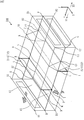
- FIG. 4 is a perspective view that transparently shows the basic configuration of the ventilation device 100 that is in the ventilation operation.
- the first damper 21 described later is represented by M, N, O and P
- the second damper 22 is represented by I, J, K and L
- the openings connected to the exhaust flow path 42 are Q and R.
- S and T The coordinates shown in FIGS. 2 to 4 are the same.
- the configuration of the ventilation device 100 will be described with reference to FIGS. 2 to 4.
- the ventilation device 100 is arranged in the attic 712.
- An inner air supply port 81 and an inner exhaust port 82 are installed on the ceiling 711.
- the control device 200 includes an outside air supply flow path 41 supplied to the room 710 and an exhaust flow path 42 for exhaust gas discharged from the room 710.
- the ventilation device 100 has an air supply flow path 41 that supplies outside air as supply air to the room, and an exhaust flow path 42 that exhausts the air from the room 710 to the room 710 as exhaust gas.
- the ventilation device 100 includes a total heat exchanger 10, a damper mechanism 20, an air supply fan 31, an exhaust fan 32, an inner outside air duct 51a, an outer outside air duct 51b, an inner exhaust duct 52a, and an outer exhaust duct 52b.
- the ventilation device 100 has a first partition plate 61, a second partition plate 62, and a housing 70.
- the first partition plate 61 is represented by E, K, L and H.
- the second partition plate 62 is represented by F1, F, G and G1.
- the housing 70 is represented by A1, B1, C1, D1, A2, B2, C2 and D2.
- a total heat exchanger 10 is sandwiched between the first partition plate 61 and the second partition plate 62. That is, the total heat exchanger 10 is arranged between the first partition plate 61 and the second partition plate 62 in the X1 direction in which the outside air advances inside the housing 70.
- the first partition plate 61 and the second partition plate 62 partition the housing 70 up and down. Specifically, the first partition plate 61 divides the space in the X1 direction from the total heat exchanger 10 into two in the Z direction, which is the direction in which the air in the room 710 is sucked into the housing 70. Further, the second partition plate 62 divides the space in the X2 direction from the total heat exchanger 10 into two in the Z direction.
- the air supply fan 31 is arranged in the air supply flow path 41, and the exhaust fan 32 is arranged in the exhaust flow path 42.
- the air supply fan 31 sucks outside air into the air supply flow path 41, and the exhaust fan 32 sucks room air into the exhaust flow path 42.
- the damper mechanism 20 includes a first damper 21 and a second damper 22. In the ventilation device 100, the air supply flow path 41 and the exhaust flow path 42 are communicated with each other by the first damper 21 during the circulation operation.
- the first damper 21 blocks the air supply flow path 41 so that the outside air does not flow into the air supply flow path 41 during the circulation operation
- the second damper mechanism 20 blocks the exhaust gas flow path 41 so that the exhaust gas does not flow out from the exhaust flow path 42.
- the exhaust flow path 42 is blocked by the damper 22.
- the damper mechanism 20 will be described.
- the damper mechanism 20 is controlled by the damper control unit 213 to switch between the circulation mode and the release mode.
- the circulation mode is a mode in which the supply of outside air through the air supply flow path 41 is cut off, the exhaust gas from the exhaust flow path 42 is cut off, and the supply air flow path 41 and the exhaust flow path 42 are communicated with each other.
- the release mode is a mode in which the circulation mode is released, and the outside air is supplied from the air supply flow path 41 to the room 710, the exhaust gas is discharged from the exhaust flow path 42, and the supply air flow path 41 and the exhaust flow path 42 It is a mode to block the communication of.
- the air supply fan 31 is in the operating state
- the exhaust fan 32 is in the stopped state
- the first damper 21 is the second state ST12 described later
- the second damper 22 is the second state ST22 described later.
- the release mode the air supply fan 31 is in the operating state
- the exhaust fan 32 is in the operating state
- the first damper 21 is the first state ST11 described later
- the second damper 22 is the first state ST21 described later.
- the circulation operation in which the air in the room 710 circulates is executed in the circulation mode of the damper mechanism 20, and the air in the room 710 does not pass through the total heat exchanger 10 in the exhaust flow path 42, the air supply flow path 41, and the room 710. Circulate.
- the ventilation operation for ventilating the room 710 is performed in the release mode of the damper mechanism 20.
- the ventilation operation by the ventilation device 100 will be described with reference to FIGS. 2 to 4.
- the total heat exchanger 10 passes the outside air of the air supply flow path 41 and the exhaust gas of the exhaust flow path 42.
- the outside air of the supply air flow path 41 and the exhaust gas of the exhaust flow path 42 exchange sensible heat and latent heat when passing through the total heat exchanger 10.
- the air supply fan 31 and the exhaust fan 32 are operating.
- the first damper 21 is the first state ST11 fitted in the first partition plate 61.
- the first damper 21 is the first state ST11 that fits into the opening 63 formed in the first partition plate 61 and closes the opening 63.
- the opening 63 is shown in FIGS. 5 to 7.
- the first partition plate 61 is represented by E, K, L and H.
- the opening 63 of the first partition plate 61 is represented by M, N, O and P.
- the first damper 21 fits into the opening 63.
- the first damper 21 blocks the air in the room 710 from flowing into the air supply flow path 41 from the opening 63.
- the second damper 22 is the first state ST21 parallel to the first partition plate 61. That is, the second damper 22 is arranged below the first partition plate 61 in the first state ST21 facing the first partition plate 61.
- the outside air is sucked into the air supply flow path 41 from the outer air supply port 91 by the air supply fan 31, passes through the total heat exchanger 10 from the bottom to the top, and passes through the air supply fan 31. , It is supplied to the room 710 from the inner air supply port 81 of the inner outside air duct 51a.
- the air in the room 710 is sucked into the exhaust flow path 42 from the inner exhaust port 82 by the exhaust fan 32, passes through the total heat exchanger 10 from the bottom to the top via the exhaust fan 32, and is outside the outer exhaust duct 52b. It is discharged from the exhaust port 92.
- both the first air conditioner 601 and the second air conditioner 602 are operating.
- the indoor unit 610 of the first air conditioner 601 is shown as an indoor unit 610a
- the indoor unit 610 of the second air conditioner 602 is shown as an indoor unit 610b
- the indoor unit 610a and the indoor unit 610b perform air conditioning. Is going. It is described as A / C ON that it is in an air-conditioned state.
- the indoor unit 610a and the indoor unit 610b are performing a cooling operation or a heating operation.
- FIG. 5 shows a room 710 when the ventilation device 100 is performing a circulating operation.
- the upward direction is the Z direction, and the left direction is the X direction.
- FIG. 6 shows a state of circulation operation by extracting the ventilation device 100 in FIG.
- FIG. 7 is a perspective view transparently showing the basic configuration of the ventilation device 100 in circulation operation.
- FIG. 8 is a diagram illustrating a system-intensive operation.
- FIG. 9 shows the effect of system intensive operation.
- the ventilation device 100 executes the circulation operation. Therefore, first, the system-intensive operation will be described with reference to FIG. In FIG. 8, only the first air conditioner 601 and the second air conditioner 602 are shown for the sake of explanation.
- the system-intensive operation will be described below.
- the system-intensive operation refers to at least one unit system among a plurality of unit systems including a plurality of unit systems including a plurality of indoor units 610 installed in a room 710 and an outdoor unit for air-conditioning a plurality of indoor units 610. The operation of stopping and operating the remaining unit system. Referring to FIG.
- the first system 701 and a second system 702 as two unit systems in which the eight indoor units 610 provided in the room 710 are divided.
- the first system 701 corresponds to the first air conditioner 601 and the second system 702 corresponds to the second air conditioner 602.
- the outdoor unit 621 that air-conditions the four indoor units 610 belonging to the first system 701 is provided in the first system 701, and the outdoor unit 622 that air-conditions the four indoor units 610 belonging to the second system 702 is the second. It is provided in the system 702.
- the plurality of systems includes a first system 701 and a second system 702.
- the system-intensive operation is an operation in which one of the first system 701 and the second system 702 is stopped and the remaining unit system is operated.
- FIG. 8 shows a state in which the first system 701 is stopped and the second system 702 is operated.
- the fact that the indoor unit 610 and the pipe 611 are separated indicates that the operation of the first system 701 is stopped.
- the energy efficiency of the air conditioner system 1 may be higher if either unit system is stopped. Therefore, when the energy efficiency is increased by stopping one of the unit systems, the operation of the unit system is stopped and the load factor per operating unit system is increased to improve the energy efficiency.
- FIG. 9 is a graph showing the improvement of COP (Coefficient Of Performance) during system-intensive operation.
- the horizontal axis is the load factor and the vertical axis is the COP.
- the operating state of two systems corresponds to point 310
- the system-intensive operation of stopping one system corresponds to point 320.
- the COP is improved by moving from the point 310 to the point 320.
- the control device 200 determines whether or not the energy efficiency is improved by the system shutdown. This determination will be described later.
- the inner air supply port 81 and the inner exhaust port 82 of the ventilation device 100 are arranged at positions where the temperature unevenness of the room 710 is reduced when the ventilation device 100 circulates during the system consolidation operation of the air conditioning system 1. Further, the ventilation device 100 is arranged at a position where the increase in carbon dioxide concentration in the room 710 can be suppressed during the ventilation operation. That is, the ventilation device 100 is arranged at a position where the ventilation efficiency is high during the ventilation operation.
- the ventilation operation by the ventilation device 100 will be described with reference to FIGS. 5 to 7.
- the air supply fan 31 is operating and the exhaust fan 32 is stopped.
- the first damper 21 is the second state ST12 as shown in FIG.
- the second state ST12 is a state in which the first damper 21 is rotated 90 degrees from the first state ST11 and the openings 63 represented by M, N, O and P appear.
- the air supply flow path 41 and the exhaust flow path 42 communicate with each other.
- the second damper 22 rotates 90 degrees from the first state ST21 to become the second state ST22 perpendicular to the first partition plate 61, and blocks the exhaust flow path 42.
- the exhaust fan 32 is stopped.
- the air supply fan 31 is operating.
- the air in the room 710 is sucked into the exhaust flow path 42 from the inner exhaust port 82 by the air supply fan 31, and circulates in the opening 63, the air supply flow path 41, the inner air supply port 81, and the room 710.
- the first air conditioner 601 is stopped by the system intensive operation, and only the second air conditioner 602 is operating.
- the indoor unit 610a is in the blowing operation, and only the indoor unit 610b performs air conditioning.
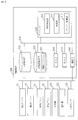
- FIG. 10 shows the hardware configuration of the control device 200.
- the control device 200 is a computer.
- the control device 200 includes a processor 210 and other hardware such as a main storage device 220, an auxiliary storage device 230, an input interface 240, an output interface 250, and a communication interface 260. In the following, the interface will be referred to as IF.
- the processor 210 is connected to other hardware via the signal line 270 and controls these other hardware.
- the control device 200 includes an aggregation determination unit 211, a determination unit 212, and a damper control unit 213 as functional elements.
- the functions of the aggregation determination unit 211, the determination unit 212, and the damper control unit 213 are realized by the control program 201.
- the control program 201 is stored in the auxiliary storage device 230.
- the processor 210 is a device that executes the control program 201.
- the control program 201 is a program that realizes the functions of the aggregation determination unit 211, the determination unit 212, and the damper control unit 213.
- the processor 210 is an IC (Integrated Circuit) that performs arithmetic processing. Specific examples of the processor 210 are a CPU (Central Processing Unit), a DSP (Digital Signal Processor), and a GPU (Graphics Processing Unit).
- the main storage device 220 is a storage device that stores data. Specific examples of the main storage device 220 are SRAM (Static Random Access Memory) and DRAM (Dynamic Random Access Memory). The main storage device 220 holds the calculation result of the processor 210.
- the auxiliary storage device 230 is a storage device that stores data in a non-volatile manner. A specific example of the auxiliary storage device 230 is an HDD (Hard Disk Drive).
- the auxiliary storage device 230 is a portable recording medium such as an SD (registered trademark) (Secure Digital) memory card, a NAND flash, a flexible disk, an optical disk, a compact disc, a Blu-ray (registered trademark) disc, or a DVD (Digital Versaille Disk). There may be.
- the input IF240 is a port to which various devices are connected and data of various devices are input.
- the output IF 250 is a port to which various devices are connected and a control signal is output to the various devices by the processor 210.
- the communication IF 260 is a communication port through which various devices and the processor 210 communicate with each other.
- a first damper 21, a second damper 22, an air supply fan 31, an exhaust fan 32, an outdoor unit 621, an outdoor unit 622, and a motion sensor 641 are connected to the communication IF 260.
- the aggregation determination unit 211 communicates with the outdoor unit 621 and the outdoor unit 622.
- the damper control unit 213 controls the first damper 21, the second damper 22, the air supply fan 31, and the exhaust fan 32.
- the processor 210 loads the control program 201 from the auxiliary storage device 230 into the main storage device 220, and reads and executes the control program 201 from the main storage device 220. Not only the control program 201 but also the OS (Operating System) is stored in the main storage device 220. The processor 210 executes the control program 201 while executing the OS.
- OS Operating System
- the control device 200 may include a plurality of processors that replace the processor 210.
- the plurality of processors share the execution of the control program 201.
- Each processor like the processor 210, is a device that executes the control program 201.
- Data, information, signal values and variable values used, processed or output by the control program 201 are stored in the main storage device 220, the auxiliary storage device 230, or the register or cache memory in the processor 210.
- the control program 201 transfers each process, each procedure, or each process in which the "unit" of each unit of the aggregation determination unit 211, the determination unit 212, and the damper control unit 213 is read as "process", “procedure”, or "process” to the computer. It is a program to be executed.
- the control method is a method performed by the control device 200, which is a computer, executing the control program 201.
- the control program 201 may be provided stored in a computer-readable recording medium, or may be provided as a program product.
- the operation of the control device 200 corresponds to the control method.
- the operation of the control device 200 corresponds to the processing of the control program 201.
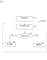
- FIG. 11 is a flowchart illustrating the operation of the ventilation device 100 and the control device 200 in the air conditioning system 1. The operation of the ventilation device 100 and the control device 200 will be described with reference to FIG.
- step S11 As shown in FIG. 2, both the first system 701 and the second system 702 are in operation.
- step S12 the aggregation determination unit 211 of the control device 200 acquires determination information used for determining whether or not to perform system aggregation operation from the outdoor unit 621 and the outdoor unit 622.
- the aggregation determination unit 211 is connected to the outdoor unit 621 and the outdoor unit 622 via the communication IF 260, and acquires the operating state of the outdoor unit 621 and the outdoor unit 622 from the outdoor unit 621 and the outdoor unit 622 as determination information. ..
- the operating state is, for example, the operating frequency of the compressors of the outdoor unit 621 and the outdoor unit 622.
- step S13 the aggregation determination unit 211 determines whether to execute the system aggregation operation based on the determination information. That is, the aggregation determination unit 211 determines whether or not to stop one of the first system 701 and the second system 702 during operation and aggregate the operation to one of them with reference to the determination information. Specifically, the aggregation determination unit 211 uses the operating frequencies of the compressors of the outdoor unit 621 and the outdoor unit 622, and it is better to execute the system aggregation operation in the relationship between the load factor and the COP shown in FIG. Determines if is higher. When the COP becomes high, the aggregation determination unit 211 determines that the system aggregation operation is executed. If YES in step S13, the process proceeds to step S14. If the COP does not increase (NO in step S13), the aggregation determination unit 211 determines that the system aggregation operation is not executed, and the process proceeds to step S16.
- step S14 the aggregation determination unit 211 stops one of the two systems and executes the system aggregation operation.
- the system aggregation operation which system to stop is set in the program that realizes the aggregation determination unit 211.
- the aggregation determination unit 211 stops, for example, the system having the lowest COP among the two systems. In this example, the aggregation determination unit 211 stops the first system 701.
- step S15 the aggregation determination unit 211 generates start information.
- the start information is information for notifying the start of system operation.
- step S16 the aggregation determination unit 211 continues the operation of the two systems.
- step S17 the aggregation determination unit 211 generates continuation information.
- the continuation information is information for notifying that the operation of the two systems is continued without executing the system intensive operation.
- step S18 the aggregation determination unit 211 outputs either the continuation information or the start information.
- the determination unit 212 acquires the relational information related to the air condition of the room 710, and decides whether to execute the circulation operation or the ventilation operation based on the relational information.
- the relationship information is start information and continuation information. Whether it is a two-system operation or a system-intensive operation is related to the air condition of the room 710.
- the damper control unit 213 controls the damper mechanism 20 to either a circulation mode or a release mode corresponding to the determined operation. To do. Specifically, it is as follows.
- the determination unit 212 receives either the continuation information or the start information, and determines whether the received information is the start information.
- step S20 If the determination unit 212 determines that the start information has been received, the process proceeds to step S20. If the determination unit 212 determines that the start information is not received, that is, if the determination unit 212 determines that the continuation information has been received, the process proceeds to step S21.
- step S20 the damper control unit 213 controls the damper mechanism 20 to put the damper mechanism 20 into the circulation mode.
- the operation of the damper mechanism 20 in the circulation mode is as follows.
- the damper control unit 213 puts the first damper 21 in the air supply cutoff state and the second damper 22 in the exhaust cutoff state. That is, as shown in FIG. 6, the damper control unit 213 changes the first damper 21 from the first state ST11 to the second state ST12, and cuts off the supply of the outside air to the room 710 by the air supply flow path 41.
- the opening 63 appears, and the air supply flow path 41 and the exhaust flow path 42 communicate with each other.
- the damper control unit 213 changes the second damper 22 from the first state ST21 to the second state ST22, and blocks the exhaust from the exhaust flow path 42 to the outside of the room. With the interruption of the air supply flow path 41 and the exhaust flow path 42, the damper control unit 213 stops the operating exhaust fan 32. For the air supply fan 31 that is in operation, the damper control unit 213 maintains the operation.
- the air in the room 710 circulates under the control of the first damper 21, the second damper 22, and the exhaust fan 32 by the damper control unit 213. That is, as shown in FIG. 6, the air in the room 710 circulates through the air supply flow path 41, the exhaust flow path 42, and the room as the circulation flow path 43.
- step S21 the damper control unit 213 maintains the ventilation operation according to the continuation information. That is, the damper control unit 213 maintains the release mode of the damper mechanism 20.
- Embodiment 1 *** Effect of Embodiment 1 ***
- the ventilation device 100 performs a circulation operation that circulates in the room 710, so that the temperature unevenness caused by the system-intensive operation can be reduced.
- system-intensive operation can be actively utilized. Therefore, in addition to being able to operate the air conditioning system 1 with high efficiency during frequent low-load operation, by combining the existing air conditioner and the existing ventilation device with the ventilation device 100, the ventilation volume satisfies the WELL standard.
- An air conditioning system can be provided.
- the ventilation device 100 that doubles as a ventilation device and a circulator is installed behind the ceiling, the equipment does not hang from the ceiling in the room, and has the effect of not giving a feeling of oppression to the resident.
- Embodiment 2 the ventilation operation and the circulation operation are switched depending on the internal state of the room 710.
- the aggregation determination unit 211 is not essential. It is assumed that the hardware configuration of the control device 200 of the second embodiment is the same as that of the control device 200 of the first embodiment.
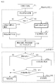
- FIG. 12 is a flowchart illustrating the operation of the ventilation device 100 and the control device 200 in the air conditioning system 1 of the second embodiment. The operation of the ventilation device 100 and the control device 200 will be described with reference to FIG.
- step S31 As shown in FIG. 2, both the first system 701 and the second system 702 are in operation.
- the determination unit 212 acquires internal information indicating at least one of the number of people present in the room 710 and the concentration of carbon dioxide in the room 710.
- the determination unit 212 refers to the inside information and determines whether to execute the circulation operation or the ventilation operation. Specifically, it is as follows.
- the determination unit 212 acquires internal information from another device.
- the number of people in the room can be obtained from a device such as an entrance / exit management device or a motion sensor provided in the room 710.
- the carbon dioxide concentration in room 710 can be obtained from a device such as a sensor that detects the carbon dioxide concentration.
- the number of people in the room is determined by information such as the operating status information of a personal computer, the location information of a smartphone, or the location information of a wearable device.
- a motion sensor will be described as an example.
- the determination unit 212 acquires information on the number of people in the room 710 from the motion sensor 641 shown in FIG. As shown in FIG. 10, the motion sensor 641 is connected to the determination unit 212 via the communication IF 260.
- Step S33> The determination unit 212 compares the internal information, which is the information of the number of people acquired from the motion sensor 641, with the threshold value TH. When the determination unit 212 determines that the number of people in the room is equal to or less than the threshold value TH, the process proceeds to step S34. If the determination unit 212 determines that the number of people in the room is larger than the threshold value TH, the process proceeds to step S35.
- step S34 the damper control unit 213 puts the damper mechanism 20 into the circulation mode. Since the circulation operation in step S34 is the same as in step S20, the description thereof will be omitted.
- step S35 the damper control unit 213 maintains the ventilation operation. Since the circulation operation in step S35 is the same as in step S20, the description thereof will be omitted.
- the ventilation operation is executed, and if the number of people in the room or the carbon dioxide concentration in the room is lower than the threshold value, the circulator operation is executed or the ventilation device. The operation of 100 is stopped.
- FIG. 13 is a flowchart illustrating the operation of the ventilation device 100 and the control device 200 in the air conditioning system 1 of the third embodiment. The operation of the ventilation device 100 and the control device 200 will be described with reference to FIG.
- the determination unit 212 acquires, as related information, start information for notifying the start of the grid-intensive operation, and internal information indicating at least one of the number of people present in the room 710 and the carbon dioxide concentration in the room 710. To do. The determination unit 212 determines whether to execute the circulation operation or the ventilation operation based on the start information and the inside information. The determination unit 212 determines the execution of the ventilation operation when either the number of people included in the inside information or the concentration of carbon dioxide exceeds the threshold value. This will be described in detail below.
- FIG. 13 is a flowchart in which steps S32 and S33 of the flowchart of FIG. 12 are incorporated between steps S19 and S20 of the flowchart of FIG. 11. In FIG.
- steps S32 and S33 are referred to as steps S32a and S33a
- step S20 in FIG. 12 is referred to as step S34a.
- the determination unit 212 waits for the acquisition of the internal information, and executes either the ventilation operation or the circulation operation according to the comparison result between the acquired internal information and the threshold value TH.
- Steps S32a, S33a, and S34a which are parts incorporated in the flowchart of FIG. 11, are the same as those of FIG. 12, so description thereof will be omitted.
- the second damper 22 may close the opening 63.
- the second damper 22 is arranged at the position of the first damper 21 in FIG. 3, and the first damper 21 is arranged at the position of the second damper 22.
- the first damper 21 is arranged on the first partition plate 61.
- FIG. 14 shows a hardware configuration of a modified example of the control device 200.
- the electronic circuit 800 of FIG. 14 is a dedicated electronic circuit that realizes the functions of the aggregation determination unit 211, the determination unit 212, the damper control unit 213, the main storage device 220, the auxiliary storage device 230, the input IF 240, the output IF 250, and the communication IF 260. is there.
- the electronic circuit 800 is connected to the signal line 801.
- the electronic circuit 800 is a single circuit, a composite circuit, a programmed processor, a parallel programmed processor, a logic IC, a GA, an ASIC, or an FPGA.
- GA is an abbreviation for Gate Array.
- ASIC is an abbreviation for Application Special Integrated Circuit.
- FPGA is an abbreviation for Field-Programmable Gate Array.
- the functions of the components of the control device 200 may be realized by one electronic circuit, or may be realized by being distributed in a plurality of electronic circuits. As another modification, some functions of the components of the control device 200 may be realized by an electronic circuit, and the remaining functions may be realized by software.
- Each of the processor 210 and the electronic circuit 800 is also called a processing circuit.
- the functions of the aggregation determination unit 211, the determination unit 212, and the damper control unit 213 may be realized by the processing circuit.
- the functions of the aggregation determination unit 211, the determination unit 212, the damper control unit 213, the main storage device 220, the auxiliary storage device 230, the input IF240, the output IF250, and the communication IF260 may be realized by the processing circuit.
Landscapes
- Engineering & Computer Science (AREA)
- Chemical & Material Sciences (AREA)
- Combustion & Propulsion (AREA)
- Mechanical Engineering (AREA)
- General Engineering & Computer Science (AREA)
- Physics & Mathematics (AREA)
- Fluid Mechanics (AREA)
- Air Conditioning Control Device (AREA)
- Ventilation (AREA)
Priority Applications (2)
| Application Number | Priority Date | Filing Date | Title |
|---|---|---|---|
| JP2021558058A JP7308969B2 (ja) | 2019-11-18 | 2019-11-18 | 換気装置 |
| PCT/JP2019/045146 WO2021100098A1 (ja) | 2019-11-18 | 2019-11-18 | 換気装置 |
Applications Claiming Priority (1)
| Application Number | Priority Date | Filing Date | Title |
|---|---|---|---|
| PCT/JP2019/045146 WO2021100098A1 (ja) | 2019-11-18 | 2019-11-18 | 換気装置 |
Publications (1)
| Publication Number | Publication Date |
|---|---|
| WO2021100098A1 true WO2021100098A1 (ja) | 2021-05-27 |
Family
ID=75981524
Family Applications (1)
| Application Number | Title | Priority Date | Filing Date |
|---|---|---|---|
| PCT/JP2019/045146 Ceased WO2021100098A1 (ja) | 2019-11-18 | 2019-11-18 | 換気装置 |
Country Status (2)
| Country | Link |
|---|---|
| JP (1) | JP7308969B2 (https=) |
| WO (1) | WO2021100098A1 (https=) |
Cited By (2)
| Publication number | Priority date | Publication date | Assignee | Title |
|---|---|---|---|---|
| JP2023005592A (ja) * | 2021-06-29 | 2023-01-18 | ダイキン工業株式会社 | 換気装置 |
| WO2024224629A1 (ja) * | 2023-04-28 | 2024-10-31 | 三菱電機株式会社 | 制御装置、換気空調システム、換気空調制御方法及びプログラム |
Citations (2)
| Publication number | Priority date | Publication date | Assignee | Title |
|---|---|---|---|---|
| WO2018109844A1 (ja) * | 2016-12-13 | 2018-06-21 | 三菱電機株式会社 | 熱交換型換気装置 |
| JP2019148342A (ja) * | 2018-02-26 | 2019-09-05 | パナソニックIpマネジメント株式会社 | 空気浄化装置およびこれを備えた熱交換形換気装置 |
Family Cites Families (1)
| Publication number | Priority date | Publication date | Assignee | Title |
|---|---|---|---|---|
| JPH0748019B2 (ja) * | 1990-06-14 | 1995-05-24 | 松下精工株式会社 | 熱交換換気空調装置 |
-
2019
- 2019-11-18 WO PCT/JP2019/045146 patent/WO2021100098A1/ja not_active Ceased
- 2019-11-18 JP JP2021558058A patent/JP7308969B2/ja active Active
Patent Citations (2)
| Publication number | Priority date | Publication date | Assignee | Title |
|---|---|---|---|---|
| WO2018109844A1 (ja) * | 2016-12-13 | 2018-06-21 | 三菱電機株式会社 | 熱交換型換気装置 |
| JP2019148342A (ja) * | 2018-02-26 | 2019-09-05 | パナソニックIpマネジメント株式会社 | 空気浄化装置およびこれを備えた熱交換形換気装置 |
Cited By (3)
| Publication number | Priority date | Publication date | Assignee | Title |
|---|---|---|---|---|
| JP2023005592A (ja) * | 2021-06-29 | 2023-01-18 | ダイキン工業株式会社 | 換気装置 |
| JP7684557B2 (ja) | 2021-06-29 | 2025-05-28 | ダイキン工業株式会社 | 換気装置 |
| WO2024224629A1 (ja) * | 2023-04-28 | 2024-10-31 | 三菱電機株式会社 | 制御装置、換気空調システム、換気空調制御方法及びプログラム |
Also Published As
| Publication number | Publication date |
|---|---|
| JPWO2021100098A1 (https=) | 2021-05-27 |
| JP7308969B2 (ja) | 2023-07-14 |
Similar Documents
| Publication | Publication Date | Title |
|---|---|---|
| US11913673B2 (en) | Method and system for utilizing a bypass humidifier for dehumidification during cooling | |
| CN113039395B (zh) | 换气调整装置以及换气调整方法 | |
| US11788761B2 (en) | Method and system for supply-air re-circulation | |
| US11306928B2 (en) | Method and apparatus for re-heat circuit operation | |
| JP7308969B2 (ja) | 換気装置 | |
| JP6809692B2 (ja) | 排気対応型床置ウォールスルー空調機及びこの空調機を備えた空調システム | |
| WO2021042437A1 (zh) | 空调系统及其控制方法 | |
| EP3663657B1 (en) | Air-conditioner and air-conditioning system | |
| JP7520156B2 (ja) | 空気調和システム、空気調和機の制御装置および空気調和機の制御方法 | |
| US10837679B2 (en) | Method and apparatus for part-load optimized refrigeration system with integrated intertwined row split condenser coil | |
| EP3795926B1 (en) | Air-conditioning system | |
| JP2018031517A (ja) | 間接外気冷房装置および間接外気冷房装置と熱冷媒を利用した冷房装置を備えた冷房システム | |
| JP5526716B2 (ja) | 空調システム | |
| JP7305043B2 (ja) | 加熱制御装置及び加熱制御プログラム | |
| US11788739B2 (en) | Method and apparatus for hybrid dehumidification | |
| JP7672506B2 (ja) | 空気処理システム | |
| WO2021205584A1 (ja) | 空気調和機管理装置及び空気調和機管理方法 | |
| EP3663673B1 (en) | Air-conditioner and air-conditioning system | |
| EP3663658A1 (en) | Air-conditioner | |
| WO2023181374A1 (ja) | 空気調和システム | |
| EP3663656B1 (en) | Air-conditioner | |
| KR100502937B1 (ko) | 공기조화기 및 그 제어 방법 | |
| JP2025105117A (ja) | 換気システム |
Legal Events
| Date | Code | Title | Description |
|---|---|---|---|
| 121 | Ep: the epo has been informed by wipo that ep was designated in this application |
Ref document number: 19953513 Country of ref document: EP Kind code of ref document: A1 |
|
| ENP | Entry into the national phase |
Ref document number: 2021558058 Country of ref document: JP Kind code of ref document: A |
|
| NENP | Non-entry into the national phase |
Ref country code: DE |
|
| 122 | Ep: pct application non-entry in european phase |
Ref document number: 19953513 Country of ref document: EP Kind code of ref document: A1 |