WO2021095484A1 - Connector device - Google Patents
Connector device Download PDFInfo
- Publication number
- WO2021095484A1 WO2021095484A1 PCT/JP2020/039867 JP2020039867W WO2021095484A1 WO 2021095484 A1 WO2021095484 A1 WO 2021095484A1 JP 2020039867 W JP2020039867 W JP 2020039867W WO 2021095484 A1 WO2021095484 A1 WO 2021095484A1
- Authority
- WO
- WIPO (PCT)
- Prior art keywords
- movable
- terminal portion
- connector
- alignment member
- movable terminal
- Prior art date
Links
Images


Classifications
-
- H—ELECTRICITY
- H01—ELECTRIC ELEMENTS
- H01R—ELECTRICALLY-CONDUCTIVE CONNECTIONS; STRUCTURAL ASSOCIATIONS OF A PLURALITY OF MUTUALLY-INSULATED ELECTRICAL CONNECTING ELEMENTS; COUPLING DEVICES; CURRENT COLLECTORS
- H01R13/00—Details of coupling devices of the kinds covered by groups H01R12/70 or H01R24/00 - H01R33/00
- H01R13/40—Securing contact members in or to a base or case; Insulating of contact members
-
- H—ELECTRICITY
- H01—ELECTRIC ELEMENTS
- H01R—ELECTRICALLY-CONDUCTIVE CONNECTIONS; STRUCTURAL ASSOCIATIONS OF A PLURALITY OF MUTUALLY-INSULATED ELECTRICAL CONNECTING ELEMENTS; COUPLING DEVICES; CURRENT COLLECTORS
- H01R13/00—Details of coupling devices of the kinds covered by groups H01R12/70 or H01R24/00 - H01R33/00
- H01R13/62—Means for facilitating engagement or disengagement of coupling parts or for holding them in engagement
- H01R13/629—Additional means for facilitating engagement or disengagement of coupling parts, e.g. aligning or guiding means, levers, gas pressure electrical locking indicators, manufacturing tolerances
- H01R13/631—Additional means for facilitating engagement or disengagement of coupling parts, e.g. aligning or guiding means, levers, gas pressure electrical locking indicators, manufacturing tolerances for engagement only
- H01R13/6315—Additional means for facilitating engagement or disengagement of coupling parts, e.g. aligning or guiding means, levers, gas pressure electrical locking indicators, manufacturing tolerances for engagement only allowing relative movement between coupling parts, e.g. floating connection
-
- H—ELECTRICITY
- H01—ELECTRIC ELEMENTS
- H01R—ELECTRICALLY-CONDUCTIVE CONNECTIONS; STRUCTURAL ASSOCIATIONS OF A PLURALITY OF MUTUALLY-INSULATED ELECTRICAL CONNECTING ELEMENTS; COUPLING DEVICES; CURRENT COLLECTORS
- H01R12/00—Structural associations of a plurality of mutually-insulated electrical connecting elements, specially adapted for printed circuits, e.g. printed circuit boards [PCB], flat or ribbon cables, or like generally planar structures, e.g. terminal strips, terminal blocks; Coupling devices specially adapted for printed circuits, flat or ribbon cables, or like generally planar structures; Terminals specially adapted for contact with, or insertion into, printed circuits, flat or ribbon cables, or like generally planar structures
- H01R12/70—Coupling devices
- H01R12/91—Coupling devices allowing relative movement between coupling parts, e.g. floating or self aligning
-
- H—ELECTRICITY
- H01—ELECTRIC ELEMENTS
- H01R—ELECTRICALLY-CONDUCTIVE CONNECTIONS; STRUCTURAL ASSOCIATIONS OF A PLURALITY OF MUTUALLY-INSULATED ELECTRICAL CONNECTING ELEMENTS; COUPLING DEVICES; CURRENT COLLECTORS
- H01R13/00—Details of coupling devices of the kinds covered by groups H01R12/70 or H01R24/00 - H01R33/00
- H01R13/46—Bases; Cases
- H01R13/516—Means for holding or embracing insulating body, e.g. casing, hoods
- H01R13/518—Means for holding or embracing insulating body, e.g. casing, hoods for holding or embracing several coupling parts, e.g. frames
-
- H—ELECTRICITY
- H01—ELECTRIC ELEMENTS
- H01R—ELECTRICALLY-CONDUCTIVE CONNECTIONS; STRUCTURAL ASSOCIATIONS OF A PLURALITY OF MUTUALLY-INSULATED ELECTRICAL CONNECTING ELEMENTS; COUPLING DEVICES; CURRENT COLLECTORS
- H01R24/00—Two-part coupling devices, or either of their cooperating parts, characterised by their overall structure
- H01R24/38—Two-part coupling devices, or either of their cooperating parts, characterised by their overall structure having concentrically or coaxially arranged contacts
- H01R24/40—Two-part coupling devices, or either of their cooperating parts, characterised by their overall structure having concentrically or coaxially arranged contacts specially adapted for high frequency
- H01R24/50—Two-part coupling devices, or either of their cooperating parts, characterised by their overall structure having concentrically or coaxially arranged contacts specially adapted for high frequency mounted on a PCB [Printed Circuit Board]
-
- H—ELECTRICITY
- H01—ELECTRIC ELEMENTS
- H01R—ELECTRICALLY-CONDUCTIVE CONNECTIONS; STRUCTURAL ASSOCIATIONS OF A PLURALITY OF MUTUALLY-INSULATED ELECTRICAL CONNECTING ELEMENTS; COUPLING DEVICES; CURRENT COLLECTORS
- H01R24/00—Two-part coupling devices, or either of their cooperating parts, characterised by their overall structure
- H01R24/38—Two-part coupling devices, or either of their cooperating parts, characterised by their overall structure having concentrically or coaxially arranged contacts
- H01R24/40—Two-part coupling devices, or either of their cooperating parts, characterised by their overall structure having concentrically or coaxially arranged contacts specially adapted for high frequency
- H01R24/54—Intermediate parts, e.g. adapters, splitters or elbows
- H01R24/542—Adapters
Definitions
- This disclosure relates to a connector device.
- Patent Document 1 discloses a connector device having a first connector and a second connector facing each other and connecting both connectors via an adapter.
- the adapter is attached so that it can swing relative to the first connector.
- the adapter is tilted to absorb the misalignment of both connectors, so that both connectors can be connected.
- each adapter may be tilted in a direction different from that of the other adapters. Therefore, when trying to connect a plurality of first connectors and a plurality of second connectors, it is difficult to connect the plurality of adapters to the second connector all at once.
- the connector of the present disclosure has been completed based on the above circumstances, and an object of the present disclosure is to provide a connector having excellent reliability of connection operation.
- the connector device of the present disclosure is A first connector mounted on the first circuit board and a second connector mounted on the second circuit board are provided.
- the first connector has a plurality of first terminal portions in a form in which the first inner conductor is surrounded by the first outer conductor.
- the second connector has a plurality of second terminal portions facing the plurality of first terminal portions, and a plurality of movable terminal portions.
- the second terminal portion has a form in which the second inner conductor is surrounded by the second outer conductor.
- the movable terminal portion can swing with the second terminal portion as a fulcrum.
- the tip of the movable terminal portion can be connected to the first terminal portion.
- the plurality of movable terminal portions are connected by an alignment member so as to swing integrally.
- the connector device of the present disclosure has excellent reliability of connection operation.
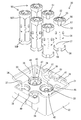
- FIG. 1 is a perspective view of the first connector.
- FIG. 2 is a perspective view showing a state in which the adapter is separated in the second connector.
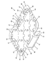
- FIG. 3 is a perspective view of the alignment member.
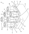
- FIG. 4 is a perspective view of the second connector.
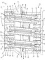
- FIG. 5 is a front sectional view of the second connector.
- FIG. 6 is a side sectional view of the second connector.
- FIG. 7 is a plan view of the second connector with the alignment member removed.
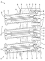
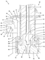
- FIG. 8 is a normal cross-sectional view in a state where the first connector and the second connector are fitted.
- the connector device of the present disclosure is (1) A first connector mounted on a first circuit board and a second connector mounted on a second circuit board are provided, and the first connector has a form in which a first inner conductor is surrounded by a first outer conductor.
- the second connector has a plurality of second terminal portions facing the plurality of first terminal portions, and a plurality of movable terminal portions. Is a form in which the second inner conductor is surrounded by the second outer conductor, the movable terminal portion can swing around the second terminal portion as a fulcrum, and the tip portion of the movable terminal portion is the first.
- the connector device of the present disclosure is excellent in connection function.
- the first connector includes a guiding portion that guides the tip portion of the movable terminal portion so as to approach the first terminal portion. According to this configuration, the tip end portion of the movable terminal portion can be reliably connected to the first terminal portion simply by bringing the first connector and the second connector close to each other.
- the guide portion surrounds the plurality of movable terminal portions. According to this configuration, since a plurality of movable terminal portions are in sliding contact with the guide portion, it is possible to prevent the load from being concentrated only on a specific movable terminal portion.
- the alignment member has holes for individually penetrating the plurality of movable terminal portions. According to this configuration, even if the movable terminal portion swings in any direction, there is no possibility that the movable terminal portion will be separated from the alignment member.
- the alignment member has a contact portion that comes into contact with the movable terminal portion in a non-fracture cross section. According to this configuration, it is possible to prevent the movable terminal portion from being damaged by the fracture surface of the alignment member.
- the movable terminal portion is a member separate from the second terminal portion, and the movable terminal portion and the second terminal portion can swing the movable terminal portion with respect to the second terminal portion. It is preferable to have a support portion that supports the body. According to this configuration, even if the second connector is oriented so that the movable terminal portion protrudes downward from the second terminal portion, the movable terminal portion can be held by the second terminal portion.
- the second connector has a housing for holding the plurality of second terminal portions, and the alignment member and the housing have a holding portion for holding the alignment member in a state of being attached to the housing. It is preferable to have it. According to this configuration, the alignment member and the housing can be integrated, so that the handling becomes easy.
- the holding portion on the alignment member side and the holding portion on the housing side face each other in a direction intersecting the displacement direction of the alignment member when the movable terminal portion swings. It is preferable to maintain a positional relationship in which the facing surface on the alignment member side and the facing surface on the housing side face each other when the alignment member has a surface and the displacement is within an allowable range. According to this configuration, when the movable terminal portion swings, the alignment member can be displaced without elastically deforming the holding portion.
- the movable terminal portion has a movable outer conductor
- the alignment member has conductivity and is in contact with a plurality of the movable outer conductors. According to this configuration, it is possible to prevent a potential difference from occurring between the plurality of movable outer conductors, so that the grounding performance is improved.
- FIGS. 1 to 8 The first embodiment of the connector device A of the present disclosure will be described with reference to FIGS. 1 to 8. It should be noted that the present invention is not limited to these examples, and is indicated by the scope of claims, and is intended to include all modifications within the meaning and scope equivalent to the scope of claims.
- the diagonally lower right direction in FIGS. 1 to 3 is defined as the front.
- the directions appearing in FIGS. 1 to 6 and 8 are defined as upward and downward as they are.
- the diagonally lower left direction in FIGS. 1 to 3 is defined as the left side.
- the connector device A of this embodiment has a first connector 10 mounted on the first circuit board B and a second connector 30 mounted on the second circuit board C. ..
- the first circuit board B is provided, for example, on a shark fin antenna (not shown) attached to the roof of an automobile (not shown).
- the first circuit board B is arranged horizontally with the mounting surface facing downward, that is, facing the inside of the vehicle.
- the second circuit board C is provided, for example, in an ECU mounted on the roof of an automobile, and is arranged horizontally with the mounting surface facing upward, that is, facing the shark fin antenna side.
- the first circuit board B and the second circuit board C are arranged in a positional relationship in which both mounting surfaces are opposed to each other in parallel.
- the first connector 10 and the second connector 30 are fitted so as to be conductive by bringing the first circuit board B closer to the second circuit board C.
- the first circuit board B and the second circuit board C are connected without using a wire harness, and high-speed communication is performed between the first circuit board B and the second circuit board C.
- the assembly tolerance between the roof and the shark fin antenna is relatively large. Therefore, a misalignment may occur between the first circuit board B and the second circuit board C in the horizontal direction intersecting the fitting directions of both connectors 10 and 30.
- the connector device A of this embodiment can fit the connectors 10 and 30 while absorbing the misalignment of the circuit boards B and C.
- the first connector 10 includes a first housing 11 and a plurality of first terminal portions 16.
- the first housing 11 is a single component made of synthetic resin having a square first terminal holding portion 12 and a square guiding portion 14.
- the first terminal holding portion 12 is formed with a plurality of first terminal accommodating chambers 13 in the form of penetrating the first terminal holding portion 12 vertically.
- the first terminal accommodating chamber 13 has a circular shape.
- the plurality of first terminal accommodating chambers 13 are arranged so as to be aligned in the front-rear direction and the left-right direction.
- the guide portion 14 has a skirt-like shape protruding diagonally downward from the outer peripheral edge at the lower end of the first terminal holding portion 12.
- the guide portion 14 is inclined so as to widen the hem downward with respect to the fitting direction of both the connectors 10 and 30.
- the guide portion 14 is continuous over the entire circumference of the first terminal holding portion 12. In a plan view, the guide portion 14 surrounds all of the plurality of first terminal accommodating chambers 13.
- the space in the first housing 11 partitioned by the guide portion 14 below the first terminal holding portion 12 functions as the first swing space 15.
- the first swing space 15 is open to the lower side of the first housing 11.
- the first terminal portion 16 includes a first inner conductor 17 made of metal, a first dielectric 21 made of synthetic resin, and a first outer conductor 22 made of metal.
- the first inner conductor 17 has a tubular shape with its axis oriented parallel to the mating direction of both connectors 10 and 30.
- the first inner conductor 17 has a small diameter portion 18, a claw portion 19 protruding in the radial direction from the outer circumference of the small diameter portion 18, and a large diameter portion 20 having a larger diameter than the small diameter portion 18.
- the small diameter portion 18 and the large diameter portion 20 are connected in the axial direction.
- the first dielectric 21 has a disk shape having a central hole.
- the first outer conductor 22 has a cylindrical shape with its axis oriented parallel to the first inner conductor 17 and the first dielectric 21.
- the first terminal portion 16 coaxially surrounds the small diameter portion 18 of the first inner conductor 17 with the first dielectric 21 and coaxially surrounds the first inner conductor 17 and the first dielectric 21 with the first outer conductor 22. It is a besieged form.
- the first dielectric 21 is located at the upper end of the first outer conductor 22.
- the space in the first outer conductor 22 below the first dielectric 21 functions as a connection space 23 open downward.
- connection space 23 the large diameter portion 20 of the first inner conductor 17 projects downward.
- Each connection space 23 communicates with the first swing space 15.
- the second connector 30 includes a second housing 31, a plurality of second terminal portions 43 having the same number as the first terminal portion 16, and a plurality of movable terminal portions 50 having the same number as the second terminal portion 43. And have.
- the lower surface of the second housing 31 is fixed to the second circuit board C, and the lower ends of the plurality of second terminal portions 43 are printed on the second circuit board C. It is connected to a circuit (not shown).
- the second housing 31 is a single component made of synthetic resin having a square second terminal holding portion 32, a square peripheral wall portion 34, and a pair of symmetrical holding protrusions 40.
- the second terminal holding portion 32 is formed with a plurality of second terminal accommodating chambers 33 having the same number as the second terminal portion 43.
- the second terminal accommodating chamber 33 has a form in which the second terminal holding portion 32 is vertically penetrated.
- the second terminal accommodating chamber 33 has a circular shape.
- the plurality of second terminal accommodating chambers 33 are arranged so as to be aligned in the front-rear direction and the left-right direction.
- the peripheral wall portion 34 has a form protruding upward from the outer peripheral edge at the upper end of the second terminal holding portion 32 in parallel with the fitting direction of both connectors 10 and 30.
- the peripheral wall portion 34 surrounds all of the plurality of second terminal accommodating chambers 33.
- the space defined by the peripheral wall portion 34 above the second terminal holding portion 32 functions as the second swing space 35.
- the second swing space 35 is open above the second housing 31, that is, toward the first connector 10.
- Notches 37 are formed in the left and right side wall portions 36 constituting the peripheral wall portion 34.
- the cutout portion 37 is in the form of a substantially square cutout downward from the upper end edge of the side wall portion 36.
- a support wall portion 38 is formed on both side wall portions 36 so as to cover the notch 37 from the outside in the left-right direction.
- the front and rear ends of the support wall portion 38 have a bent shape and are connected to the outer surface of the side wall portion 36.
- the space partitioned by the support wall portion 38 functions as a holding space 39 communicating with the second swinging space 35 via the notch portion 37.
- Holding protrusions 40 are formed on the inner surface of both the left and right support wall portions 38.
- the holding protrusion 40 projects into the holding space 39 from the central portion in the front-rear direction of the support wall portion 38.
- a guide slope 41 inclined so as to descend from the support wall portion 38 side toward the second swing space 35 side is formed.
- the lower surface of the holding protrusion 40 functions as a fixed-side facing surface 42 that intersects the fitting directions of both connectors 10 and 30.
- the second terminal portion 43 includes a second inner conductor 44 made of metal, a second dielectric 45 made of synthetic resin, and a second outer conductor 46 made of metal.
- the second inner conductor 44 is the same component as the first inner conductor 17, and has a small diameter portion 18, a claw portion 19, and a large diameter portion 20.
- the second inner conductor 44 is arranged in the axial direction opposite to that of the first inner conductor 17.
- the second dielectric 45 is the same component as the first dielectric 21, and is arranged upside down from the first dielectric 21 in the axial direction.
- the second outer conductor 46 has a cylindrical shape with its axis oriented parallel to the second inner conductor 44 and the second dielectric 45.
- the second terminal portion 43 coaxially surrounds the small diameter portion 18 of the second inner conductor 44 with the second dielectric 45, and coaxially surrounds the second inner conductor 44 and the second dielectric 45 with the second outer conductor 46. It is a besieged form.
- the second dielectric 45 is located at the lower end of the second outer conductor 46.
- the space in the second outer conductor 46 above the second dielectric 45 functions as a support space 47 open upward. In the support space 47, the large diameter portion 20 of the second inner conductor 44 projects upward.
- Each support space 47 communicates with the second swing space 35.
- a continuous diameter-reduced portion 48 is formed on the inner circumference of the upper end portion of the second outer conductor 46 over the entire circumference.
- the reduced diameter portion 48 is arranged in the support space 47 and has a shape that bulges inward in the radial direction.
- the movable terminal portion 50 has an elongated shape as a whole.
- the movable terminal portion 50 has symmetry that gives the same shape when both ends in the axial direction are inverted.
- the movable terminal portion 50 is a member including a metal movable inner conductor 51, a synthetic resin movable dielectric 53, and a metal movable outer conductor 56.
- a pair of elastic claw pieces 52 that can be elastically deformed in the radial direction are formed at both ends of the movable inner conductor 51 in the axial direction.
- the movable dielectric 53 is made of synthetic resin and has a cylindrical shape coaxial with the axis of the movable terminal portion 50.
- An insertion hole 54 in the form of coaxially penetrating the movable dielectric 53 is formed in the central portion of the movable dielectric 53.
- circular accommodating recesses 55 are formed at both ends of the movable dielectric 53 in the axial direction.
- the accommodating recess 55 is a space forming both ends in the axial direction of the insertion hole 54.
- the inner diameter of the accommodating recess 55 is larger than the inner diameter of the insertion hole 54.
- the movable outer conductor 56 has a cylindrical shape as a whole. As shown in FIGS. 2 and 5, a plurality of elastic arm portions 57 arranged at intervals in the circumferential direction are formed at both ends of the movable outer conductor 56 in the axial direction.
- the elastic arm portion 57 has a cantilevered shape extending toward the end side in the axial direction, and can be elastically deformed in the radial direction.
- a diameter-expanded portion 58 is formed at the extending end of the elastic arm portion 57.
- the movable terminal portion 50 has a form in which the movable inner conductor 51 is inserted into the insertion hole 54 of the movable dielectric 53, and the movable outer conductor 56 is fitted on the outer circumference of the movable dielectric 53.
- the elastic claw piece 52 of the movable inner conductor 51 is located in the accommodating recess 55.
- a bending space that allows elastic deformation of the elastic arm portion 57 is provided between the outer circumferences of both ends of the movable dielectric 53 in the axial direction and the inner circumference of the elastic arm portion 57 of the movable outer conductor 56. 59 is secured.
- One end of the movable terminal portion 50 is attached to the second terminal portion 43 as a base end portion 50P of the movable terminal portion 50.
- the base end portion 50P of the movable terminal portion 50 is inserted into the support space 47 of the second connector 30.
- the large diameter portion 20 of the second inner conductor 44 is accommodated in the accommodating recess 55, and the elastic claw piece 52 of the movable inner conductor 51 is the second inner conductor. It makes elastic contact with the inner circumference of the large diameter portion 20 of 44.
- the elastic arm portion 57 of the movable outer conductor 56 is elastically deformed, and the enlarged diameter portion 58 elastically contacts the inner circumference of the second outer conductor 46.
- the movable terminal portion 50 By locking the enlarged diameter portion 58 of the movable outer conductor 56 to the reduced diameter portion 48 of the second outer conductor 46, it is regulated that the movable terminal portion 50 is separated from the second terminal portion 43. Even if the movable terminal portion 50 is turned upside down so as to project downward from the second terminal portion 43, the locked state of the enlarged diameter portion 58 and the reduced diameter portion 48 is maintained.
- the plurality of movable terminal portions 50 can individually swing with the contact portion between the base end portion 50P and the second terminal portion 43 as a fulcrum. Even if the movable terminal portion 50 swings in the front-rear direction or the left-right direction with respect to the second terminal portion 43, the locked state of the enlarged diameter portion 58 and the reduced diameter portion 48 is maintained.
- the movable terminal portion 50 attached to the second terminal portion 43 has a form protruding upward from the second housing 31.
- the other end of the movable terminal portion 50 that is, the upper end portion, is connected to the first terminal portion 16 as the tip portion 50T of the movable terminal portion 50.
- one movable terminal portion 50 is supported in a state of being in contact with only one second terminal portion 43, the plurality of movable terminal portions 50 are individually supported in different directions from the other movable terminal portions 50. It can swing.
- the tip portions 50T of the plurality of movable terminal portions 50 are subjected to a plurality of first portions. It cannot be connected to one terminal portion 16 at the same time.
- the second connector 30 is provided with an alignment member 60.
- the alignment member 60 is a single component formed by bending a metal plate material punched into a predetermined shape by press working. As shown in FIG. 3, the alignment member 60 has a plate-shaped main body 61 and a pair of symmetrical elastic holding pieces 68.
- the plate-shaped main body 61 has a flat plate shape in which the plate thickness direction is parallel to the fitting direction of both connectors 10 and 30.
- the plate-shaped main body portion 61 has the same shape as the peripheral wall portion 34 of the second housing 31 in a plan view.
- the plate-shaped main body 61 is formed with a plurality of holes 62 having the same arrangement as the plurality of second terminal 43s in a plan view.
- the hole portion 62 has a circular shape having an inner diameter larger than the outer diameter of the movable outer conductor 56, and penetrates the plate-shaped main body portion 61 in the vertical direction.
- a plurality of fixed protrusions 63 spaced apart from each other in the circumferential direction are formed on the inner circumference of the hole 62.
- the fixed protrusion 63 is formed by closely bending the tip of the extension extending from the inner circumference of the hole 62 toward the center in the radial direction so as to fold back downward.
- the outer peripheral surface of the protruding end of the fixed protrusion 63 functions as a fixed contact portion 64 having a semicircular curved surface.
- the entire region of the fixed contact portion 64 is composed of only a non-fracture cross section different from the fracture surface generated by press working on the surface of the alignment member 60.
- the diameter of the protruding ends of the plurality of fixed protrusions 63, that is, the inscribed circle inscribed in the plurality of fixed contact portions 64, is the same as or slightly larger than the outer diameter of the movable outer conductor 56. ..
- a plurality of elastic contact pieces 65 arranged so as to overlap the upper surface of the plate-shaped main body 61 are integrally formed on the plate-shaped main body 61.
- the plan view shape of the elastic contact piece 65 is an arc shape.
- One elastic contact piece 65 has a form extending in a cantilever shape along the opening edge of one hole 62 with the outer peripheral edge of the plate-shaped main body 61 as a base point.
- a movable protrusion 66 is formed at the extending end of the elastic contact piece 65.
- the movable protrusion 66 is formed by closely bending the tip of the extension portion extending from the inner circumference of the extension end portion of the elastic contact piece 65 toward the center in the radial direction so as to fold back upward.
- the outer peripheral surface of the protruding end of the movable protrusion 66 functions as a movable contact portion 67 having a semicircular curved surface shape.
- the entire region of the movable contact portion 67 is composed of only a non-broken cross section.
- the elastic holding piece 68 includes a pair of front and rear leg portions 69 extending downward at right angles to the plate-shaped main body portion 61 from the side edge of the plate-shaped main body portion 61, and extending ends of both leg portions 69. It has a locking portion 70 that connects the two.
- the locking portion 70 has a plate shape parallel to the plate-shaped main body portion 61.
- the upper surface of the locking portion 70 is a movable side facing surface 71.
- the movable side facing surface 71 faces the fixed side facing surface 42 in the vertical direction parallel to the fitting direction of both connectors 10 and 30.
- the elastic holding piece 68 is formed with a guided portion 72 that projects diagonally downward from the inner side edge of the locking portion 70.
- the alignment member 60 is attached to the second housing 31 by approaching the second housing 31 from above.
- the pair of guided portions 72 are in sliding contact with the pair of guide slopes 41, so that the pair of elastic holding pieces 68 are elastically deformed so as to be displaced in the direction of approaching each other, that is, toward the second swing space 35 side. ..
- the pair of elastic holding pieces 68 elastically return so as to be separated from each other and are housed in the holding space 39.
- the movable side facing surface 71 of the elastic holding piece 68 faces the fixed side facing surface 42 of the second housing 31 from below.
- the alignment member 60 is attached to the second housing 31, the outer peripheral edge portion of the plate-shaped main body portion 61 is placed on the upper end surface of the peripheral wall portion 34, and the leg portion 69 and the locking portion 70 are housed in the holding space 39. Then, the locking portion 70 slips under the holding protrusion 40. By locking the locking portion 70 to the holding projection 40, the alignment member 60 is restricted from being detached from the second housing 31. In a state where the outer peripheral edge of the plate-shaped main body portion 61 is aligned with the peripheral wall portion 34, a clearance is secured between the leg portion 69 and the support wall portion 38 and between the locking portion 70 and the support wall portion 38.
- the alignment member 60 is held in a state in which the relative displacement in the direction parallel to the plate-shaped main body 61 is allowed with respect to the second housing 31.
- the direction parallel to the plate-shaped main body 61 is a direction that intersects the fitting directions of both connectors 10 and 30 at right angles, and is a direction in which misalignment of both circuit boards B and C is assumed.
- the amount of relative displacement of the alignment member 60 with respect to the second housing 31 is maximum when the leg portion 69 or the locking portion 70 comes into contact with the support wall portion 38.
- the relative displacement amount of the alignment member 60 is maximized, at least a part of the movable side facing surface 71 is kept in a state of vertically facing at least a part of the fixed side facing surface 42. Therefore, even if the displacement amount of the alignment member 60 is maximum, the alignment member 60 is held in a state of being attached to the second housing 31.
- a plurality of movable terminal portions 50 are attached to the second terminal portion 43.
- the base end portion 50P of the movable terminal portion 50 is inserted into the hole portion 62 and entered into the second swinging space 35, and is fitted into the support space 47 of the second terminal portion 43.
- the alignment member 60 may be attached to the second housing 31 after the movable terminal portion 50 is attached to the second terminal portion 43.
- the outer circumference of the movable outer conductor 56 is surrounded by the hole edge portion of the hole portion 62 over the entire circumference. Since the fixed contact portion 64 and the movable contact portion 67 abut on the outer circumference of the movable outer conductor 56, the movable terminal portion 50 causes a relative displacement of the alignment member 60 in a direction parallel to the plate-shaped main body portion 61. It is kept in a regulated state.
- the alignment member 60 is made of a metal material and has conductivity.
- the portion where the alignment member 60 comes into contact with the movable outer conductor 56 is the region between the elastic arm portion 57 on the base end portion 50P side and the elastic arm portion 57 on the tip end portion 50T side in the axial direction of the movable terminal portion 50. is there. Therefore, neither the fixed contact portion 64 nor the movable contact portion 67 comes into contact with the elastic arm portion 57. As a result, damage or deformation of the elastic arm portion 57 is prevented.
- the relative displacement of each movable terminal portion 50 with respect to the alignment member 60 is regulated, the relative displacement between the movable terminal portions 50 is regulated by the alignment member 60.
- all the movable terminal portions 50 are integrally swung together with the alignment member 60 in the same direction and by the same angle. Therefore, the positional relationship of the tip portions 50T of all the movable terminal portions 50 is maintained at a constant positional relationship regardless of the swing direction and the swing angle of the movable terminal portions 50.
- the maintained positional relationship is the same as that of the plurality of first terminal portions 16.
- the movable terminal portion 50 swings around the connection portion between the second terminal portion 43 and the base end portion 50P of the movable terminal portion 50 as a fulcrum.
- the swing angle of the movable terminal portion 50 becomes maximum when the movable terminal portion 50 comes into contact with the peripheral wall portion 34.
- the amount of displacement of the alignment member 60 when the movable terminal portion 50 is tilted increases as the contact position of the alignment member 60 approaches the tip portion 50T of the movable terminal portion 50.
- the pressing force generated between the movable terminal portion 50 and the alignment member 60 is such that the contact position of the alignment member 60 is the movable terminal. The closer to the base end portion 50P of the portion 50, the larger the size.
- the contact position of the alignment member 60 is an intermediate position between the base end portion 50P and the tip end portion 50T, the movable terminal portion 50 and the movable terminal portion 50 while suppressing the displacement amount of the alignment member 60 when the movable terminal portion 50 is tilted.
- the pressing force generated between the alignment member 60 and the alignment member 60 can be reduced.
- the tip portion 50T of any of the movable terminal portions 50 is guided. It comes into contact with the inner surface of the portion 14.
- the tip portion 50T of the movable terminal portion 50 is in sliding contact with the inclined inner surface of the guide portion 14, so that the tip portions 50T of all the movable terminal portions 50 are brought into contact with each other. , While changing the swing angle all at once, it is guided to the connection position with the first terminal portion 16.
- the base end portion 50P of the movable terminal portion 50 swings in the second swing space 35, and the tip end portion 50T of the movable terminal portion 50 swings in the first swing space 15.
- the tip portion 50T of the movable terminal portion 50 passes through the guide portion 14, it enters the connection space 23 of the first terminal portion 16 and is connected to the first terminal portion 16.
- the first connector 10 and the second connector 30 are in a normal mating state.
- both connectors 10 and 30 are normally fitted, the first circuit board B and the second circuit board C are connected via the first terminal portion 16, the alignment member 60, and the second terminal portion 43.
- the movable inner conductor 51 is inserted through the insertion hole 54 of the movable dielectric 53 with a clearance. Therefore, the movable inner conductor 51 can be relatively displaced with respect to the movable dielectric 53 and the movable outer conductor 56 in such a manner that the axes are tilted. As a result, even when the movable terminal portion 50 swings and the axis of the movable terminal portion 50 is tilted with respect to the axes of the first terminal portion 16 and the second terminal portion 43, the inside of the first unit is not limited to the swing angle.
- the connector device A of this embodiment includes a first connector 10 mounted on the first circuit board B and a second connector 30 mounted on the second circuit board C.
- the first connector 10 has a plurality of first terminal portions 16 in a form in which the first inner conductor 17 is surrounded by the first outer conductor 22.
- the second connector 30 has a plurality of second terminal portions 43 facing the plurality of first terminal portions 16, and a plurality of movable terminal portions 50.
- the second terminal portion 43 has a form in which the second inner conductor 44 is surrounded by the second outer conductor 46.
- the movable terminal portion 50 can swing with the second terminal portion 43 as a fulcrum.
- the tip portion 50T of the movable terminal portion 50 can be connected to the first terminal portion 16.
- the plurality of movable terminal portions 50 are connected by an alignment member 60 so as to swing integrally.
- the plurality of movable terminal portions 50 swing integrally by the alignment member 60. Therefore, no matter what angle and in what direction the movable terminal portion 50 swings, the tip portions 50T of the plurality of movable terminal portions 50 have the same positional relationship as the arrangement form of the plurality of first terminal portions 16. keep. As a result, the plurality of movable terminal portions 50 are securely connected to the plurality of first terminal portions 16. Therefore, the connector device A of this embodiment is excellent in the reliability of the connection operation.
- the first connector 10 includes a guide portion 14 that guides the tip portion 50T of the movable terminal portion 50 so as to approach the first terminal portion 16.
- the guide portion 14 has a form in which all of the plurality of movable terminal portions 50 are collectively enclosed in the fitting process of both the connectors 10 and 30. According to this configuration, since the plurality of movable terminal portions 50 are in sliding contact with the guide portion 14, it is possible to prevent the load from being concentrated only on the specific movable terminal portion 50.
- the alignment member 60 has a plurality of holes 62 through which the plurality of movable terminal portions 50 are individually penetrated.
- the inner peripheral edge of the hole 62 surrounds the movable terminal 50 over the entire circumference. Therefore, even if the movable terminal portion 50 swings in any direction, there is no possibility that the movable terminal portion 50 will be separated from the alignment member 60.
- the alignment member 60 has a fixed contact portion 64 and a movable contact portion 67 that come into contact with the movable outer conductor 56 of the movable terminal portion 50 in a non-fracture cross section. Therefore, it is possible to prevent the outer peripheral surface of the movable outer conductor 56 from being damaged by the fracture surface of the alignment member 60.
- the movable terminal portion 50 is a separate member from the second terminal portion 43.
- the movable outer conductor 56 of the movable terminal portion 50 has a diameter-expanded portion 58.
- the second outer conductor 46 of the second terminal portion 43 has a reduced diameter portion 48.
- the enlarged diameter portion 58 and the reduced diameter portion 48 function as support portions that swingably support the movable terminal portion 50 with respect to the second terminal portion 43. According to this configuration, even if the second connector 30 is oriented so that the movable terminal portion 50 projects downward from the second terminal portion 43, the movable terminal portion 50 can be held by the second terminal portion 43. it can.
- the second connector 30 has a second housing 31 and a plurality of second terminal portions 43.
- the second housing 31 holds a plurality of second terminal portions 43.
- the alignment member 60 has an elastic holding piece 68, and the second housing 31 has a holding protrusion 40.
- the elastic holding piece 68 and the holding protrusion 40 function as a holding portion for holding the alignment member 60 in a state of being attached to the second housing 31. According to this configuration, the alignment member 60 and the housing can be integrated, so that the handling becomes easy.
- the elastic holding piece 68 which is a holding portion on the alignment member 60 side, has a movable side facing surface 71
- the holding protrusion 40 which is a holding portion on the second housing 31 side, has a fixed side facing surface 42.
- the movable side facing surface 71 and the fixed side facing surface 42 face each other in a direction intersecting the displacement direction of the alignment member 60 when the movable terminal portion 50 swings.
- the alignment member 60 is within the allowable displacement range, the movable side facing surface 71 and the fixed side facing surface 42 maintain a positional relationship facing each other. According to this configuration, when the movable terminal portion 50 swings, the alignment member 60 can be displaced without elastically deforming the elastic holding piece 68.
- the connector device A of this embodiment includes a plurality of first terminal portions 16 mounted on the first circuit board B, a plurality of second terminal portions 43 mounted on the second circuit board C, and a plurality of movable terminal portions. 50 and an alignment member 60 are provided.
- the first terminal portion 16 has a first outer conductor 22 that surrounds the first inner conductor 17.
- the second terminal portion 43 has a second outer conductor 46 that surrounds the second inner conductor 44.
- the movable terminal portion 50 has a movable outer conductor 56 that surrounds the movable inner conductor 51.
- the movable terminal portion 50 can swing with the second terminal portion 43 as a fulcrum.
- the tip portion 50T of the movable terminal portion 50 can be connected to the first terminal portion 16.
- the alignment member 60 is made of a conductive material.
- the alignment member 60 has a function as a connecting member that short-circuits a plurality of movable outer conductors 56 with each other. Since the plurality of movable outer conductors 56 are conducted with each other via the alignment member 60, no potential difference is generated between the plurality of movable outer conductors 56. As a result, there is no potential difference between the plurality of first outer conductors 22, and there is no potential difference between the plurality of second outer conductors 46. Therefore, the connector device A of this embodiment is excellent in grounding performance.
- the alignment member 60 has an elastic contact piece 65 that makes elastic contact with the movable outer conductor 56. Since the elastic contact piece 65 has a cantilevered shape extending along the outer circumference of the movable outer conductor 56, even if the movable terminal portion 50 is displaced in the radial direction with respect to the alignment member 60, the elastic contact piece 65 remains. It flexibly follows the movement of the movable terminal portion 50. As a result, the contact state between the alignment member 60 and the movable outer conductor 56 is stabilized, so that the alignment member 60 and the movable outer conductor 56 can be reliably kept in contact with each other.
- the present invention is not limited to the examples described in the above description and drawings, but is shown by the scope of claims.
- the present invention includes the meaning equivalent to the scope of claims and all modifications within the scope of claims, and is intended to include the following embodiments.
- the movable terminal portion is a separate member from the second terminal portion, but the movable terminal portion may be integrated with the second terminal portion.
- one guide portion surrounds a plurality of second terminal portions, but one guide portion may surround only one second terminal portion. Even in this case, since one movable terminal portion is guided by the guiding portion, a plurality of movable terminal portions can be connected to the plurality of second terminal portions.
- the alignment member is provided with a plurality of holes for individually penetrating the plurality of movable terminal portions, but the movable terminal portions are held by the alignment member by a plurality of arm portions or the like spaced apart in the circumferential direction. You may do so.
- the protrusion is formed on the inner circumference of the hole, but the inner peripheral edge of the hole may have a shape without unevenness over the entire circumference.
- the fixed contact portion and the movable contact portion having a non-fracture cross section come into contact with the movable terminal portion, but the fracture surface may come into contact with the movable terminal portion.
- the holding portion for holding the alignment member in the detachment restricted state is provided with respect to the second terminal portion, but such a holding portion may not be provided.
- the holding portion (elastic holding piece) of the alignment member and the holding portion (holding protrusion) of the second housing can be relatively displaced, but both holding portions are fitted in a form that cannot be relatively displaced. It may have been done.
- the alignment member can be moved by elastically deforming at least one of the holding portion of the alignment member and the holding portion of the housing.
- the alignment member has conductivity, but the alignment member may not have conductivity.
- Plate-shaped main body 62 ... Hole 63 ... Fixed protrusion 64 ... Fixed contact (contact) 65 ... Elastic contact piece 66 ... Movable protrusion 67 ... Movable contact part (contact part) 68 ... Elastic holding piece (holding part of alignment member) 69 ... Leg 70 ... Locking portion 71 ... Movable side facing surface (opposing surface) 72 ... Guided portion A ... Connector device B ... First circuit board C ... Second circuit board
Abstract
Provided is a connector device having excellent connection operation reliability. The connector device (A) includes a first connector (10) mounted on a first circuit board (B) and a second connector (30) mounted on a second circuit board (C), wherein the first connector (10) has a plurality of first terminal parts (16) in a form in which a first inner conductor (17) is surrounded by a first outer conductor (22), the second connector (30) has a plurality of second terminal parts (43) facing the plurality of first terminal parts (16) and a plurality of movable terminal parts (50), the second terminal parts (43) have a form in which a second inner conductor (44) is surrounded by a second outer conductor (46), the movable terminal parts (50) can swing with the second terminal parts (43) as a supporting point, tip portions (50T) of the movable terminal parts (50) can be connected to the first terminal parts (16), and the plurality of movable terminal parts (50) are connected by an alignment member (60) to be integrally swingable.
Description
本開示は、コネクタ装置に関するものである。
This disclosure relates to a connector device.
特許文献1には、互いに対向する第1コネクタと第2コネクタを有し、両コネクタをアダプターを介して接続するコネクタ装置が開示されている。アダプターは、第1コネクタに相対的に揺動し得るように取り付けられる。第1コネクタと第2コネクタが対向方向と交差する方向へ位置ずれしたときには、アダプターが傾くことによって両コネクタの位置ずれが吸収されるので、両コネクタを接続させることができる。
Patent Document 1 discloses a connector device having a first connector and a second connector facing each other and connecting both connectors via an adapter. The adapter is attached so that it can swing relative to the first connector. When the first connector and the second connector are misaligned in the direction in which they intersect with each other, the adapter is tilted to absorb the misalignment of both connectors, so that both connectors can be connected.
第1コネクタと第2コネクタをアダプターを介して接続する上記の接続構造を、多極のコネクタ装置に適用した場合、次のような問題が懸念される。アダプターは第1コネクタに対して自在に揺動可能なので、第1コネクタと第2コネクタが未嵌合の状態では、各アダプターが他のアダプターとは異なる方向へ傾いた状態になり得る。そのため、複数の第1コネクタと複数の第2コネクタを接続しようとしたときに、複数のアダプターを一斉に第2コネクタに接続させることが難しい。
When the above connection structure for connecting the first connector and the second connector via an adapter is applied to a multi-pole connector device, the following problems are concerned. Since the adapter can swing freely with respect to the first connector, when the first connector and the second connector are not fitted, each adapter may be tilted in a direction different from that of the other adapters. Therefore, when trying to connect a plurality of first connectors and a plurality of second connectors, it is difficult to connect the plurality of adapters to the second connector all at once.
本開示のコネクタは、上記のような事情に基づいて完成されたものであって、接続動作の信頼性に優れたコネクタを提供することを目的とする。
The connector of the present disclosure has been completed based on the above circumstances, and an object of the present disclosure is to provide a connector having excellent reliability of connection operation.
本開示のコネクタ装置は、
第1回路基板に実装される第1コネクタと、第2回路基板に実装される第2コネクタとを備え、
前記第1コネクタは、第1内導体を第1外導体で包囲した形態の複数の第1端子部を有し、
前記第2コネクタは、前記複数の第1端子部と対向する複数の第2端子部と、複数の可動端子部とを有し、
前記第2端子部は、第2内導体を第2外導体で包囲した形態であり、
前記可動端子部は、前記第2端子部を支点として揺動可能であり、
前記可動端子部の先端部は、前記第1端子部に対して接続可能であり、
前記複数の可動端子部は、アライメント部材によって一体的に揺動するように連結されている。 The connector device of the present disclosure is
A first connector mounted on the first circuit board and a second connector mounted on the second circuit board are provided.
The first connector has a plurality of first terminal portions in a form in which the first inner conductor is surrounded by the first outer conductor.
The second connector has a plurality of second terminal portions facing the plurality of first terminal portions, and a plurality of movable terminal portions.
The second terminal portion has a form in which the second inner conductor is surrounded by the second outer conductor.
The movable terminal portion can swing with the second terminal portion as a fulcrum.
The tip of the movable terminal portion can be connected to the first terminal portion.
The plurality of movable terminal portions are connected by an alignment member so as to swing integrally.
本開示のコネクタ装置は、接続動作の信頼性に優れている。
The connector device of the present disclosure has excellent reliability of connection operation.
[本開示の実施形態の説明]
最初に本開示の実施形態を列記して説明する。
本開示のコネクタ装置は、
(1)第1回路基板に実装される第1コネクタと、第2回路基板に実装される第2コネクタとを備え、前記第1コネクタは、第1内導体を第1外導体で包囲した形態の複数の第1端子部を有し、前記第2コネクタは、前記複数の第1端子部と対向する複数の第2端子部と、複数の可動端子部とを有し、前記第2端子部は、第2内導体を第2外導体で包囲した形態であり、前記可動端子部は、前記第2端子部を支点として揺動可能であり、前記可動端子部の先端部は、前記第1端子部に対して接続可能であり、前記複数の可動端子部は、アライメント部材によって一体的に揺動するように連結されている。本開示の構成によれば、複数の可動端子部がアライメント部材によって一体的に揺動するので、複数の可動端子部の先端部が、複数の第1端子部の配列形態と同じ位置関係に保たれる。これにより、複数の可動端子部が複数の第1端子部に対して確実に接続される。したがって、本開示のコネクタ装置は接続機能に優れている。 [Explanation of Embodiments of the present disclosure]
First, the embodiments of the present disclosure will be listed and described.
The connector device of the present disclosure is
(1) A first connector mounted on a first circuit board and a second connector mounted on a second circuit board are provided, and the first connector has a form in which a first inner conductor is surrounded by a first outer conductor. The second connector has a plurality of second terminal portions facing the plurality of first terminal portions, and a plurality of movable terminal portions. Is a form in which the second inner conductor is surrounded by the second outer conductor, the movable terminal portion can swing around the second terminal portion as a fulcrum, and the tip portion of the movable terminal portion is the first. It can be connected to the terminal portion, and the plurality of movable terminal portions are connected by an alignment member so as to swing integrally. According to the configuration of the present disclosure, since the plurality of movable terminal portions swing integrally by the alignment member, the tip portions of the plurality of movable terminal portions are maintained in the same positional relationship as the arrangement form of the plurality of first terminal portions. Dripping. As a result, the plurality of movable terminal portions are securely connected to the plurality of first terminal portions. Therefore, the connector device of the present disclosure is excellent in connection function.
(2)前記第1コネクタは、前記可動端子部の前記先端部を前記第1端子部へ接近するように誘導する誘導部を備えていることが好ましい。この構成によれば、第1コネクタと第2コネクタを接近させるだけで、可動端子部の先端部を第1端子部に確実に接続させることができる。
(2) It is preferable that the first connector includes a guiding portion that guides the tip portion of the movable terminal portion so as to approach the first terminal portion. According to this configuration, the tip end portion of the movable terminal portion can be reliably connected to the first terminal portion simply by bringing the first connector and the second connector close to each other.
(3)(2)において、前記誘導部が、前記複数の可動端子部を包囲する形態であることが好ましい。この構成によれば、複数の可動端子部が誘導部に摺接するので、特定の可動端子部のみに負荷が集中することを回避できる。
In (3) and (2), it is preferable that the guide portion surrounds the plurality of movable terminal portions. According to this configuration, since a plurality of movable terminal portions are in sliding contact with the guide portion, it is possible to prevent the load from being concentrated only on a specific movable terminal portion.
(4)前記アライメント部材は、前記複数の可動端子部を個別に貫通させる孔部を有していることが好ましい。この構成によれば、可動端子部がいずれの方向へ揺動した場合でも、可動端子部がアライメント部材から離脱するおそれはない。
(4) It is preferable that the alignment member has holes for individually penetrating the plurality of movable terminal portions. According to this configuration, even if the movable terminal portion swings in any direction, there is no possibility that the movable terminal portion will be separated from the alignment member.
(5)前記アライメント部材は、非破断面において前記可動端子部に接触する当接部を有していることが好ましい。この構成によれば、アライメント部材の破断面によって可動端子部が傷付けられることを防止できる。
(5) It is preferable that the alignment member has a contact portion that comes into contact with the movable terminal portion in a non-fracture cross section. According to this configuration, it is possible to prevent the movable terminal portion from being damaged by the fracture surface of the alignment member.
(6)前記可動端子部は前記第2端子部とは別体の部材であり、前記可動端子部と前記第2端子部は、前記可動端子部を前記第2端子部に対して揺動可能に支持する支持部を有していることが好ましい。この構成によれば、第2コネクタが、可動端子部を第2端子部から下方へ突出させる向きになっても、可動端子部を第2端子部に保持させておくことができる。
(6) The movable terminal portion is a member separate from the second terminal portion, and the movable terminal portion and the second terminal portion can swing the movable terminal portion with respect to the second terminal portion. It is preferable to have a support portion that supports the body. According to this configuration, even if the second connector is oriented so that the movable terminal portion protrudes downward from the second terminal portion, the movable terminal portion can be held by the second terminal portion.
(7)前記第2コネクタは、前記複数の第2端子部を保持するハウジングを有しており、前記アライメント部材と前記ハウジングは、前記アライメント部材を前記ハウジングに取り付けた状態に保持する保持部を有していることが好ましい。この構成によれば、アライメント部材とハウジングを一体化させておくことができるので、取り扱いが容易となる。
(7) The second connector has a housing for holding the plurality of second terminal portions, and the alignment member and the housing have a holding portion for holding the alignment member in a state of being attached to the housing. It is preferable to have it. According to this configuration, the alignment member and the housing can be integrated, so that the handling becomes easy.
(8)(7)において、前記アライメント部材側の前記保持部と、前記ハウジング側の前記保持部は、前記可動端子部の揺動時における前記アライメント部材の変位方向と交差する方向に対向する対向面を有し、前記アライメント部材が変位を許容された範囲内にあるときに、前記アライメント部材側の前記対向面と前記ハウジング側の前記対向面が対向した位置関係を保つことが好ましい。この構成によれば、可動端子部が揺動するときに、保持部を弾性変形させなくても、アライメント部材を変位させることができる。
(8) In (7), the holding portion on the alignment member side and the holding portion on the housing side face each other in a direction intersecting the displacement direction of the alignment member when the movable terminal portion swings. It is preferable to maintain a positional relationship in which the facing surface on the alignment member side and the facing surface on the housing side face each other when the alignment member has a surface and the displacement is within an allowable range. According to this configuration, when the movable terminal portion swings, the alignment member can be displaced without elastically deforming the holding portion.
(9)前記可動端子部が可動外導体を有しており、前記アライメント部材が、導電性を有し、複数の前記可動外導体と接触可能であることが好ましい。この構成によれば、複数の可動外導体相互間で電位差が生じないようにすることができるので、アース性能が向上する。
(9) It is preferable that the movable terminal portion has a movable outer conductor, and the alignment member has conductivity and is in contact with a plurality of the movable outer conductors. According to this configuration, it is possible to prevent a potential difference from occurring between the plurality of movable outer conductors, so that the grounding performance is improved.
[本開示の実施形態の詳細]
[実施例1]
本開示のコネクタ装置Aを具体化した実施例1を、図1~図8を参照して説明する。なお、本発明はこれらの例示に限定されるものではなく、特許請求の範囲によって示され、特許請求の範囲と均等の意味および範囲内でのすべての変更が含まれることが意図される。本実施例1において、前後の方向については、図1~3における斜め右下方向方を前方と定義する。上下の方向については、図1~6,8にあらわれる向きを、そのまま上方、下方と定義する。左右の方向については、図1~3における斜め左下方向を、左方と定義する。 [Details of Embodiments of the present disclosure]
[Example 1]
The first embodiment of the connector device A of the present disclosure will be described with reference to FIGS. 1 to 8. It should be noted that the present invention is not limited to these examples, and is indicated by the scope of claims, and is intended to include all modifications within the meaning and scope equivalent to the scope of claims. In the first embodiment, with respect to the front-back direction, the diagonally lower right direction in FIGS. 1 to 3 is defined as the front. Regarding the vertical direction, the directions appearing in FIGS. 1 to 6 and 8 are defined as upward and downward as they are. Regarding the left-right direction, the diagonally lower left direction in FIGS. 1 to 3 is defined as the left side.
本実施例のコネクタ装置Aは、図8に示すように、第1回路基板Bに実装される第1コネクタ10と、第2回路基板Cに実装される第2コネクタ30とを有している。第1回路基板Bは、例えば、自動車の屋根(図示省略)に取り付けられるシャークフィンアンテナ(図示省略)に設けられるものである。第1回路基板Bは、実装面を下向き、つまり車内側に向けた状態で水平に配置される。第2回路基板Cは、例えば、自動車の屋根に取り付けられたECUに設けられるものであり、実装面を上向き、つまりシャークフィンアンテナ側に向けた状態で水平に配置される。第1回路基板Bと第2回路基板Cは、双方の実装面同士を平行に対向させた位置関係で配置される。
As shown in FIG. 8, the connector device A of this embodiment has a first connector 10 mounted on the first circuit board B and a second connector 30 mounted on the second circuit board C. .. The first circuit board B is provided, for example, on a shark fin antenna (not shown) attached to the roof of an automobile (not shown). The first circuit board B is arranged horizontally with the mounting surface facing downward, that is, facing the inside of the vehicle. The second circuit board C is provided, for example, in an ECU mounted on the roof of an automobile, and is arranged horizontally with the mounting surface facing upward, that is, facing the shark fin antenna side. The first circuit board B and the second circuit board C are arranged in a positional relationship in which both mounting surfaces are opposed to each other in parallel.
第1コネクタ10と第2コネクタ30は、第1回路基板Bを第2回路基板Cに接近させることによって導通可能に嵌合される。両コネクタ10,30が嵌合することにより、第1回路基板Bと第2回路基板Cがワイヤーハーネスを介さずに接続され、第1回路基板Bと第2回路基板Cとの間で高速通信が可能となる。自動車の屋根におけるシャークフィンアンテナの取付け部分では、屋根とシャークフィンアンテナとの間の組付け公差が比較的大きい。そのため、両コネクタ10,30の嵌合方向と交差する水平方向において、第1回路基板Bと第2回路基板Cとの間で位置ずれが生じ得る。本実施例のコネクタ装置Aは、両回路基板B,Cの位置ずれを吸収しながら両コネクタ10,30の嵌合を行えるようになっている。
The first connector 10 and the second connector 30 are fitted so as to be conductive by bringing the first circuit board B closer to the second circuit board C. By fitting both connectors 10 and 30, the first circuit board B and the second circuit board C are connected without using a wire harness, and high-speed communication is performed between the first circuit board B and the second circuit board C. Is possible. At the mounting portion of the shark fin antenna on the roof of an automobile, the assembly tolerance between the roof and the shark fin antenna is relatively large. Therefore, a misalignment may occur between the first circuit board B and the second circuit board C in the horizontal direction intersecting the fitting directions of both connectors 10 and 30. The connector device A of this embodiment can fit the connectors 10 and 30 while absorbing the misalignment of the circuit boards B and C.
第1コネクタ10は、図8に示すように、第1ハウジング11と、複数の第1端子部16とを備えている。第1コネクタ10を第1回路基板Bに実装した状態では、第1ハウジング11の上面が第1回路基板Bに固定され、複数の第1端子部16の上端部が第1回路基板Bのプリント回路(図示省略)に接続される。第1ハウジング11は、直方形の第1端子保持部12と方形の誘導部14とを有する合成樹脂製の単一部品である。第1端子保持部12には、第1端子保持部12を上下に貫通した形態の複数の第1端子収容室13が形成されている。第1コネクタ10を上から見た平面視において、第1端子収容室13は円形をなす。複数の第1端子収容室13は、前後方向及び左右方向に整列するように配置されている。
As shown in FIG. 8, the first connector 10 includes a first housing 11 and a plurality of first terminal portions 16. In a state where the first connector 10 is mounted on the first circuit board B, the upper surface of the first housing 11 is fixed to the first circuit board B, and the upper ends of the plurality of first terminal portions 16 are printed on the first circuit board B. It is connected to a circuit (not shown). The first housing 11 is a single component made of synthetic resin having a square first terminal holding portion 12 and a square guiding portion 14. The first terminal holding portion 12 is formed with a plurality of first terminal accommodating chambers 13 in the form of penetrating the first terminal holding portion 12 vertically. When the first connector 10 is viewed from above, the first terminal accommodating chamber 13 has a circular shape. The plurality of first terminal accommodating chambers 13 are arranged so as to be aligned in the front-rear direction and the left-right direction.
誘導部14は、第1端子保持部12の下端における外周縁から斜め下方へスカート状に突出した形態である。誘導部14は、両コネクタ10,30の嵌合方向に対し、下方に向かって裾広がりとなるように傾斜している。誘導部14は、第1端子保持部12の全周に亘って連続している。平面視において、誘導部14は、複数の第1端子収容室13の全てを包囲している。第1ハウジング11内のうち、第1端子保持部12よりも下方において誘導部14により区画された空間は、第1揺動空間15として機能する。第1揺動空間15は、第1ハウジング11の下方へ開放されている。
The guide portion 14 has a skirt-like shape protruding diagonally downward from the outer peripheral edge at the lower end of the first terminal holding portion 12. The guide portion 14 is inclined so as to widen the hem downward with respect to the fitting direction of both the connectors 10 and 30. The guide portion 14 is continuous over the entire circumference of the first terminal holding portion 12. In a plan view, the guide portion 14 surrounds all of the plurality of first terminal accommodating chambers 13. The space in the first housing 11 partitioned by the guide portion 14 below the first terminal holding portion 12 functions as the first swing space 15. The first swing space 15 is open to the lower side of the first housing 11.
複数の第1端子収容室13内には、複数の第1端子部16が個別に収容されている。図8に示すように、第1端子部16は、金属製の第1内導体17と、合成樹脂製の第1誘電体21と、金属製の第1外導体22とを備えている。第1内導体17は、軸線を両コネクタ10,30の嵌合方向と平行に向けた筒形をなす。第1内導体17は、小径部18と、小径部18の外周から径方向に突出した爪部19と、小径部18よりも径寸法の大きい大径部20とを有する。小径部18と大径部20は軸線方向に連なっている。第1誘電体21は、中心孔を有する円盤形をなす。第1外導体22は、軸線を第1内導体17及び第1誘電体21と平行に向けた円筒形をなす。
A plurality of first terminal portions 16 are individually accommodated in the plurality of first terminal accommodating chambers 13. As shown in FIG. 8, the first terminal portion 16 includes a first inner conductor 17 made of metal, a first dielectric 21 made of synthetic resin, and a first outer conductor 22 made of metal. The first inner conductor 17 has a tubular shape with its axis oriented parallel to the mating direction of both connectors 10 and 30. The first inner conductor 17 has a small diameter portion 18, a claw portion 19 protruding in the radial direction from the outer circumference of the small diameter portion 18, and a large diameter portion 20 having a larger diameter than the small diameter portion 18. The small diameter portion 18 and the large diameter portion 20 are connected in the axial direction. The first dielectric 21 has a disk shape having a central hole. The first outer conductor 22 has a cylindrical shape with its axis oriented parallel to the first inner conductor 17 and the first dielectric 21.
第1端子部16は、第1内導体17の小径部18を第1誘電体21で同軸状に包囲し、第1内導体17と第1誘電体21を第1外導体22で同軸状に包囲した形態である。第1誘電体21は第1外導体22の上端部に位置する。第1外導体22内のうち第1誘電体21よりも下方の空間は、下方へ開放された接続空間23として機能する。接続空間23内においては、第1内導体17の大径部20が下向きに突出している。各接続空間23は第1揺動空間15と連通している。
The first terminal portion 16 coaxially surrounds the small diameter portion 18 of the first inner conductor 17 with the first dielectric 21 and coaxially surrounds the first inner conductor 17 and the first dielectric 21 with the first outer conductor 22. It is a besieged form. The first dielectric 21 is located at the upper end of the first outer conductor 22. The space in the first outer conductor 22 below the first dielectric 21 functions as a connection space 23 open downward. In the connection space 23, the large diameter portion 20 of the first inner conductor 17 projects downward. Each connection space 23 communicates with the first swing space 15.
図2に示すように、第2コネクタ30は、第2ハウジング31と、第1端子部16と同数の複数の第2端子部43と、第2端子部43と同数の複数の可動端子部50とを備えている。第2コネクタ30を第2回路基板Cに実装した状態では、第2ハウジング31の下面が第2回路基板Cに固定され、複数の第2端子部43の下端部が第2回路基板Cのプリント回路(図示省略)に接続される。第2ハウジング31は、直方形の第2端子保持部32と、方形の周壁部34と、左右対称な一対の保持突起40とを有する合成樹脂製の単一部品である。
As shown in FIG. 2, the second connector 30 includes a second housing 31, a plurality of second terminal portions 43 having the same number as the first terminal portion 16, and a plurality of movable terminal portions 50 having the same number as the second terminal portion 43. And have. In a state where the second connector 30 is mounted on the second circuit board C, the lower surface of the second housing 31 is fixed to the second circuit board C, and the lower ends of the plurality of second terminal portions 43 are printed on the second circuit board C. It is connected to a circuit (not shown). The second housing 31 is a single component made of synthetic resin having a square second terminal holding portion 32, a square peripheral wall portion 34, and a pair of symmetrical holding protrusions 40.
第2端子保持部32には、第2端子部43と同数の複数の第2端子収容室33が形成されている。第2端子収容室33は、第2端子保持部32を上下に貫通した形態である。第2コネクタ30を上から見た平面視において、第2端子収容室33は円形をなす。複数の第2端子収容室33は、複数の第1端子収容室13と同じく、前後方向及び左右方向に整列するように配置されている。
The second terminal holding portion 32 is formed with a plurality of second terminal accommodating chambers 33 having the same number as the second terminal portion 43. The second terminal accommodating chamber 33 has a form in which the second terminal holding portion 32 is vertically penetrated. When the second connector 30 is viewed from above, the second terminal accommodating chamber 33 has a circular shape. Like the plurality of first terminal accommodating chambers 13, the plurality of second terminal accommodating chambers 33 are arranged so as to be aligned in the front-rear direction and the left-right direction.
図2に示すように、周壁部34は、第2端子保持部32の上端における外周縁から、両コネクタ10,30の嵌合方向と平行に上方へ突出した形態である。平面視において、周壁部34は、複数の第2端子収容室33の全てを包囲している。第2ハウジング31のうち、第2端子保持部32よりも上方において周壁部34により区画された空間は、第2揺動空間35として機能する。第2揺動空間35は、第2ハウジング31の上方、即ち第1コネクタ10側へ開放されている。周壁部34を構成する左右両側壁部36には、切欠部37が形成されている。切欠部37は、側壁部36の上端縁から下方へ略方形に切り欠いた形態である。
As shown in FIG. 2, the peripheral wall portion 34 has a form protruding upward from the outer peripheral edge at the upper end of the second terminal holding portion 32 in parallel with the fitting direction of both connectors 10 and 30. In a plan view, the peripheral wall portion 34 surrounds all of the plurality of second terminal accommodating chambers 33. Of the second housing 31, the space defined by the peripheral wall portion 34 above the second terminal holding portion 32 functions as the second swing space 35. The second swing space 35 is open above the second housing 31, that is, toward the first connector 10. Notches 37 are formed in the left and right side wall portions 36 constituting the peripheral wall portion 34. The cutout portion 37 is in the form of a substantially square cutout downward from the upper end edge of the side wall portion 36.
両側壁部36には、切欠部37を左右方向外方から覆う形態の支持壁部38が形成されている。支持壁部38の前後両端部は、屈曲形状をなしていて側壁部36の外側面に連なっている。支持壁部38によって区画された空間は、切欠部37を介して第2揺動空間35と連通した保持空間39として機能する。左右両支持壁部38の内側面には、保持突起40が形成されている。保持突起40は、支持壁部38の前後方向中央部から保持空間39内に突出している。図6に示すように、保持突起40の上面には、支持壁部38側から第2揺動空間35側に向かって下るように傾斜したガイド斜面41が形成されている。保持突起40の下面は、両コネクタ10,30の嵌合方向と交差する固定側対向面42として機能する。
A support wall portion 38 is formed on both side wall portions 36 so as to cover the notch 37 from the outside in the left-right direction. The front and rear ends of the support wall portion 38 have a bent shape and are connected to the outer surface of the side wall portion 36. The space partitioned by the support wall portion 38 functions as a holding space 39 communicating with the second swinging space 35 via the notch portion 37. Holding protrusions 40 are formed on the inner surface of both the left and right support wall portions 38. The holding protrusion 40 projects into the holding space 39 from the central portion in the front-rear direction of the support wall portion 38. As shown in FIG. 6, on the upper surface of the holding projection 40, a guide slope 41 inclined so as to descend from the support wall portion 38 side toward the second swing space 35 side is formed. The lower surface of the holding protrusion 40 functions as a fixed-side facing surface 42 that intersects the fitting directions of both connectors 10 and 30.
図5に示すように、複数の第2端子収容室33内には、複数の第2端子部43が個別に収容されている。図6に示すように、第2端子部43は、金属製の第2内導体44と、合成樹脂製の第2誘電体45と、金属製の第2外導体46とを備えている。第2内導体44は、第1内導体17と同一の部品であり、小径部18と爪部19と大径部20とを有する。第2内導体44は、軸線方向において第1内導体17とは逆向きに配置されている。第2誘電体45は、第1誘電体21と同一の部品であり、軸線方向において第1誘電体21とは上下逆向きに配置されている。第2外導体46は、軸線を第2内導体44及び第2誘電体45と平行に向けた円筒形をなす。
As shown in FIG. 5, a plurality of second terminal portions 43 are individually accommodated in the plurality of second terminal accommodating chambers 33. As shown in FIG. 6, the second terminal portion 43 includes a second inner conductor 44 made of metal, a second dielectric 45 made of synthetic resin, and a second outer conductor 46 made of metal. The second inner conductor 44 is the same component as the first inner conductor 17, and has a small diameter portion 18, a claw portion 19, and a large diameter portion 20. The second inner conductor 44 is arranged in the axial direction opposite to that of the first inner conductor 17. The second dielectric 45 is the same component as the first dielectric 21, and is arranged upside down from the first dielectric 21 in the axial direction. The second outer conductor 46 has a cylindrical shape with its axis oriented parallel to the second inner conductor 44 and the second dielectric 45.
第2端子部43は、第2内導体44の小径部18を第2誘電体45で同軸状に包囲し、第2内導体44と第2誘電体45を第2外導体46で同軸状に包囲した形態である。第2誘電体45は第2外導体46の下端部に位置する。第2外導体46内のうち第2誘電体45よりも上方の空間は、上方へ開放された支持空間47として機能する。支持空間47内においては、第2内導体44の大径部20が上向きに突出している。各支持空間47は第2揺動空間35と連通している。第2外導体46の上端部内周には、全周に亘って連続した縮径部48が形成されている。縮径部48は、支持空間47内に配置され、径方向内側へ膨らむような形状である。
The second terminal portion 43 coaxially surrounds the small diameter portion 18 of the second inner conductor 44 with the second dielectric 45, and coaxially surrounds the second inner conductor 44 and the second dielectric 45 with the second outer conductor 46. It is a besieged form. The second dielectric 45 is located at the lower end of the second outer conductor 46. The space in the second outer conductor 46 above the second dielectric 45 functions as a support space 47 open upward. In the support space 47, the large diameter portion 20 of the second inner conductor 44 projects upward. Each support space 47 communicates with the second swing space 35. A continuous diameter-reduced portion 48 is formed on the inner circumference of the upper end portion of the second outer conductor 46 over the entire circumference. The reduced diameter portion 48 is arranged in the support space 47 and has a shape that bulges inward in the radial direction.
図2,5に示すように、可動端子部50は、全体として細長い形状をなす。可動端子部50は、軸線方向両端部を反転させたときに同一の形状となる対称性を有している。図5に示すように、可動端子部50は、金属製の可動内導体51と、合成樹脂製の可動誘電体53と、金属製の可動外導体56とを備えて構成された部材である。可動内導体51の軸線方向両端部には、それぞれ、径方向へ弾性変形可能な一対の弾性爪片52が形成されている。
As shown in FIGS. 2 and 5, the movable terminal portion 50 has an elongated shape as a whole. The movable terminal portion 50 has symmetry that gives the same shape when both ends in the axial direction are inverted. As shown in FIG. 5, the movable terminal portion 50 is a member including a metal movable inner conductor 51, a synthetic resin movable dielectric 53, and a metal movable outer conductor 56. A pair of elastic claw pieces 52 that can be elastically deformed in the radial direction are formed at both ends of the movable inner conductor 51 in the axial direction.
可動誘電体53は、合成樹脂製であり、可動端子部50の軸線と同軸状の円筒形をなす。可動誘電体53の中心部には、可動誘電体53を同軸状に貫通した形態の挿通孔54が形成されている。可動誘電体53の軸線方向両端部には、可動誘電体53の両端面を同軸状に凹ませた形態の円形の収容凹部55が形成されている。収容凹部55は、挿通孔54の軸線方向両端部を構成する空間である。収容凹部55の内径は挿通孔54の内径よりも大きい。
The movable dielectric 53 is made of synthetic resin and has a cylindrical shape coaxial with the axis of the movable terminal portion 50. An insertion hole 54 in the form of coaxially penetrating the movable dielectric 53 is formed in the central portion of the movable dielectric 53. At both ends of the movable dielectric 53 in the axial direction, circular accommodating recesses 55 in which both end faces of the movable dielectric 53 are coaxially recessed are formed. The accommodating recess 55 is a space forming both ends in the axial direction of the insertion hole 54. The inner diameter of the accommodating recess 55 is larger than the inner diameter of the insertion hole 54.
可動外導体56は、全体として円筒形をなす。図2,5に示すように、可動外導体56の軸線方向両端部には、周方向に間隔を空けて配された複数の弾性アーム部57が形成されている。弾性アーム部57は、軸線方向端部側へ片持ち状に延出した形態であり、径方向へ弾性変形することが可能である。弾性アーム部57の延出端部には、拡径部58が形成されている。
The movable outer conductor 56 has a cylindrical shape as a whole. As shown in FIGS. 2 and 5, a plurality of elastic arm portions 57 arranged at intervals in the circumferential direction are formed at both ends of the movable outer conductor 56 in the axial direction. The elastic arm portion 57 has a cantilevered shape extending toward the end side in the axial direction, and can be elastically deformed in the radial direction. A diameter-expanded portion 58 is formed at the extending end of the elastic arm portion 57.
可動端子部50は、可動誘電体53の挿通孔54内に可動内導体51を挿通し、可動誘電体53の外周に可動外導体56を嵌合した形態である。可動内導体51の弾性爪片52は、収容凹部55内に位置する。図6に示すように、可動誘電体53の軸線方向両端部の外周と、可動外導体56の弾性アーム部57の内周との間には、弾性アーム部57の弾性変形を許容する撓み空間59が確保されている。
The movable terminal portion 50 has a form in which the movable inner conductor 51 is inserted into the insertion hole 54 of the movable dielectric 53, and the movable outer conductor 56 is fitted on the outer circumference of the movable dielectric 53. The elastic claw piece 52 of the movable inner conductor 51 is located in the accommodating recess 55. As shown in FIG. 6, a bending space that allows elastic deformation of the elastic arm portion 57 is provided between the outer circumferences of both ends of the movable dielectric 53 in the axial direction and the inner circumference of the elastic arm portion 57 of the movable outer conductor 56. 59 is secured.
可動端子部50の一方の端部は、可動端子部50の基端部50Pとして第2端子部43に取り付けられている。取り付けに際しては、可動端子部50の基端部50Pを第2コネクタ30の支持空間47内に挿入する。可動端子部50を第2端子部43に取り付けた状態では、収容凹部55内に第2内導体44の大径部20が収容され、可動内導体51の弾性爪片52が、第2内導体44の大径部20の内周に対し弾性的に接触する。可動外導体56の弾性アーム部57が弾性変形し、拡径部58が、第2外導体46の内周に対し弾性的に接触する。
One end of the movable terminal portion 50 is attached to the second terminal portion 43 as a base end portion 50P of the movable terminal portion 50. At the time of attachment, the base end portion 50P of the movable terminal portion 50 is inserted into the support space 47 of the second connector 30. In a state where the movable terminal portion 50 is attached to the second terminal portion 43, the large diameter portion 20 of the second inner conductor 44 is accommodated in the accommodating recess 55, and the elastic claw piece 52 of the movable inner conductor 51 is the second inner conductor. It makes elastic contact with the inner circumference of the large diameter portion 20 of 44. The elastic arm portion 57 of the movable outer conductor 56 is elastically deformed, and the enlarged diameter portion 58 elastically contacts the inner circumference of the second outer conductor 46.
可動外導体56の拡径部58が第2外導体46の縮径部48に係止することにより、可動端子部50が第2端子部43から離脱することを規制される。可動端子部50が第2端子部43から下方へ突出するように上下反転させた向きにしても、拡径部58と縮径部48との係止状態が保たれる。複数の可動端子部50は、基端部50Pと第2端子部43との接触部分を支点として、個別に揺動することが可能である。可動端子部50が第2端子部43に対して前後方向又は左右方向へ揺動しても、拡径部58と縮径部48との係止状態が保たれる。
By locking the enlarged diameter portion 58 of the movable outer conductor 56 to the reduced diameter portion 48 of the second outer conductor 46, it is regulated that the movable terminal portion 50 is separated from the second terminal portion 43. Even if the movable terminal portion 50 is turned upside down so as to project downward from the second terminal portion 43, the locked state of the enlarged diameter portion 58 and the reduced diameter portion 48 is maintained. The plurality of movable terminal portions 50 can individually swing with the contact portion between the base end portion 50P and the second terminal portion 43 as a fulcrum. Even if the movable terminal portion 50 swings in the front-rear direction or the left-right direction with respect to the second terminal portion 43, the locked state of the enlarged diameter portion 58 and the reduced diameter portion 48 is maintained.
第2端子部43に取り付けた可動端子部50は、第2ハウジング31から上方へ突出した形態である。可動端子部50の他方の端部、即ち上端部は、可動端子部50の先端部50Tとして、第1端子部16と接続するようになっている。ここで、1つの可動端子部50は1つの第2端子部43のみに接触した状態で支持されているので、複数の可動端子部50は、他の可動端子部50とは異なる方向へ個別に揺動し得るようになっている。しかし、複数の可動端子部50が互いに異なる方向へ揺動した状態では、第1コネクタ10と第2コネクタ30を嵌合するときに、複数の可動端子部50の先端部50Tを、複数の第1端子部16に対して同時に接続させることができない。
The movable terminal portion 50 attached to the second terminal portion 43 has a form protruding upward from the second housing 31. The other end of the movable terminal portion 50, that is, the upper end portion, is connected to the first terminal portion 16 as the tip portion 50T of the movable terminal portion 50. Here, since one movable terminal portion 50 is supported in a state of being in contact with only one second terminal portion 43, the plurality of movable terminal portions 50 are individually supported in different directions from the other movable terminal portions 50. It can swing. However, in a state where the plurality of movable terminal portions 50 swing in different directions, when the first connector 10 and the second connector 30 are fitted, the tip portions 50T of the plurality of movable terminal portions 50 are subjected to a plurality of first portions. It cannot be connected to one terminal portion 16 at the same time.
その対策として、第2コネクタ30には、アライメント部材60が設けられている。アライメント部材60は、プレス加工により所定形状に打ち抜いた金属製の板材に、曲げ加工を施して成形された単一部品である。図3に示すように、アライメント部材60は、板状本体部61と、左右対称な一対の弾性保持片68とを有する。板状本体部61は、板厚方向を両コネクタ10,30の嵌合方向と平行に向けた平板状をなす。板状本体部61は、平面視において第2ハウジング31の周壁部34と同じ形状をなしている。
As a countermeasure, the second connector 30 is provided with an alignment member 60. The alignment member 60 is a single component formed by bending a metal plate material punched into a predetermined shape by press working. As shown in FIG. 3, the alignment member 60 has a plate-shaped main body 61 and a pair of symmetrical elastic holding pieces 68. The plate-shaped main body 61 has a flat plate shape in which the plate thickness direction is parallel to the fitting direction of both connectors 10 and 30. The plate-shaped main body portion 61 has the same shape as the peripheral wall portion 34 of the second housing 31 in a plan view.
板状本体部61には、平面視において複数の第2端子部43と同じ配置の複数の孔部62が形成されている。孔部62は、可動外導体56の外径よりも内径寸法の大きい円形をなし、板状本体部61を上下方向に貫通した形態である。孔部62の内周には、周方向に間隔を空けた複数の固定突起部63が形成されている。固定突起部63は、孔部62の内周から径方向中心側へ延出した延出部の先端部を、下側へ折り返するように密着曲げして形成されている。
The plate-shaped main body 61 is formed with a plurality of holes 62 having the same arrangement as the plurality of second terminal 43s in a plan view. The hole portion 62 has a circular shape having an inner diameter larger than the outer diameter of the movable outer conductor 56, and penetrates the plate-shaped main body portion 61 in the vertical direction. A plurality of fixed protrusions 63 spaced apart from each other in the circumferential direction are formed on the inner circumference of the hole 62. The fixed protrusion 63 is formed by closely bending the tip of the extension extending from the inner circumference of the hole 62 toward the center in the radial direction so as to fold back downward.
固定突起部63の突出端部の外周面は、半円弧形の曲面状をなす固定当接部64として機能する。固定当接部64の全領域は、アライメント部材60の表面のうちプレス加工によって生じる破断面とは異なる非破断面のみによって構成されている。複数の固定突起部63の突出端、即ち複数の固定当接部64に内接する内接円の直径寸法は、可動外導体56の外径と同じ寸法か、それよりも僅かに大きい寸法である。
The outer peripheral surface of the protruding end of the fixed protrusion 63 functions as a fixed contact portion 64 having a semicircular curved surface. The entire region of the fixed contact portion 64 is composed of only a non-fracture cross section different from the fracture surface generated by press working on the surface of the alignment member 60. The diameter of the protruding ends of the plurality of fixed protrusions 63, that is, the inscribed circle inscribed in the plurality of fixed contact portions 64, is the same as or slightly larger than the outer diameter of the movable outer conductor 56. ..
板状本体部61には、板状本体部61の上面に重なるように配された複数の弾性接触片65が一体に形成されている。弾性接触片65の平面視形状は円弧形をなす。1つの弾性接触片65は、板状本体部61の外周縁を基点とし、1つの孔部62の開口縁に沿って片持ち状に延出した形態である。弾性接触片65の延出端部には、可動突起部66が形成されている。可動突起部66は、弾性接触片65の延出端部の内周から径方向中心側へ延出した延出部の先端部を、上側へ折り返するように密着曲げして形成されている。可動突起部66の突出端部の外周面は、半円弧形の曲面状をなす可動当接部67として機能する。可動当接部67の全領域は、固定当接部64と同様、非破断面のみによって構成されている。
A plurality of elastic contact pieces 65 arranged so as to overlap the upper surface of the plate-shaped main body 61 are integrally formed on the plate-shaped main body 61. The plan view shape of the elastic contact piece 65 is an arc shape. One elastic contact piece 65 has a form extending in a cantilever shape along the opening edge of one hole 62 with the outer peripheral edge of the plate-shaped main body 61 as a base point. A movable protrusion 66 is formed at the extending end of the elastic contact piece 65. The movable protrusion 66 is formed by closely bending the tip of the extension portion extending from the inner circumference of the extension end portion of the elastic contact piece 65 toward the center in the radial direction so as to fold back upward. The outer peripheral surface of the protruding end of the movable protrusion 66 functions as a movable contact portion 67 having a semicircular curved surface shape. Like the fixed contact portion 64, the entire region of the movable contact portion 67 is composed of only a non-broken cross section.
図3に示すように、弾性保持片68は、板状本体部61の側縁から板状本体部61と直角に下方へ延出した前後一対の脚部69と、両脚部69の延出端同士を連結する係止部70とを有する。係止部70は、板状本体部61と平行な板状をなす。図3,7に示すように、係止部70の上面は、可動側対向面71となっている。可動側対向面71は、固定側対向面42に対し両コネクタ10,30の嵌合方向と平行な上下方向に対向するようになっている。弾性保持片68には、係止部70の内側の側縁から斜め下方へ張り出した被ガイド部72が形成されている。
As shown in FIG. 3, the elastic holding piece 68 includes a pair of front and rear leg portions 69 extending downward at right angles to the plate-shaped main body portion 61 from the side edge of the plate-shaped main body portion 61, and extending ends of both leg portions 69. It has a locking portion 70 that connects the two. The locking portion 70 has a plate shape parallel to the plate-shaped main body portion 61. As shown in FIGS. 3 and 7, the upper surface of the locking portion 70 is a movable side facing surface 71. The movable side facing surface 71 faces the fixed side facing surface 42 in the vertical direction parallel to the fitting direction of both connectors 10 and 30. The elastic holding piece 68 is formed with a guided portion 72 that projects diagonally downward from the inner side edge of the locking portion 70.
アライメント部材60は、第2ハウジング31に対し上方から接近させることによって、第2ハウジング31に取り付けられている。取り付ける過程では、一対の被ガイド部72が一対のガイド斜面41に摺接することにより、一対の弾性保持片68が互いに接近する方向、つまり第2揺動空間35側へ変位するように弾性変形する。被ガイド部72と係止部70が保持突起40を通過すると、一対の弾性保持片68は、互いに離間するように弾性復帰して、保持空間39内に収容される。弾性保持片68の可動側対向面71は、第2ハウジング31の固定側対向面42に対し下から対向する。以上により、第2ハウジング31に対するアライメント部材60の組付けが完了する。
The alignment member 60 is attached to the second housing 31 by approaching the second housing 31 from above. In the mounting process, the pair of guided portions 72 are in sliding contact with the pair of guide slopes 41, so that the pair of elastic holding pieces 68 are elastically deformed so as to be displaced in the direction of approaching each other, that is, toward the second swing space 35 side. .. When the guided portion 72 and the locking portion 70 pass through the holding projection 40, the pair of elastic holding pieces 68 elastically return so as to be separated from each other and are housed in the holding space 39. The movable side facing surface 71 of the elastic holding piece 68 faces the fixed side facing surface 42 of the second housing 31 from below. As described above, the assembly of the alignment member 60 with respect to the second housing 31 is completed.
第2ハウジング31にアライメント部材60を取り付けた状態では、板状本体部61の外周縁部が周壁部34の上端面に載置され、脚部69と係止部70が保持空間39内に収容され、係止部70が保持突起40の下側に潜り込む。係止部70が保持突起40に係止することにより、アライメント部材60は第2ハウジング31からの離脱を規制される。板状本体部61の外周縁が周壁部34と整合する状態では、脚部69と支持壁部38との間及び係止部70と支持壁部38との間にクリアランスが確保されている。
In a state where the alignment member 60 is attached to the second housing 31, the outer peripheral edge portion of the plate-shaped main body portion 61 is placed on the upper end surface of the peripheral wall portion 34, and the leg portion 69 and the locking portion 70 are housed in the holding space 39. Then, the locking portion 70 slips under the holding protrusion 40. By locking the locking portion 70 to the holding projection 40, the alignment member 60 is restricted from being detached from the second housing 31. In a state where the outer peripheral edge of the plate-shaped main body portion 61 is aligned with the peripheral wall portion 34, a clearance is secured between the leg portion 69 and the support wall portion 38 and between the locking portion 70 and the support wall portion 38.
したがって、アライメント部材60は、第2ハウジング31に対し、板状本体部61と平行な方向への相対変位を許容された状態に保持される。板状本体部61と平行な方向は、両コネクタ10,30の嵌合方向と直角に交差する方向であり、両回路基板B,Cの位置ずれが想定される方向である。第2ハウジング31に対するアライメント部材60の相対変位量は、脚部69又は係止部70が支持壁部38に当接したときが最大となる。アライメント部材60の相対変位量が最大になった状態では、可動側対向面71の少なくとも一部が、固定側対向面42の少なくとも一部に対し上下方向に対向する状態を保つ。したがって、アライメント部材60の変位量が最大であっても、アライメント部材60は第2ハウジング31に取り付けられた状態に保持される。
Therefore, the alignment member 60 is held in a state in which the relative displacement in the direction parallel to the plate-shaped main body 61 is allowed with respect to the second housing 31. The direction parallel to the plate-shaped main body 61 is a direction that intersects the fitting directions of both connectors 10 and 30 at right angles, and is a direction in which misalignment of both circuit boards B and C is assumed. The amount of relative displacement of the alignment member 60 with respect to the second housing 31 is maximum when the leg portion 69 or the locking portion 70 comes into contact with the support wall portion 38. In the state where the relative displacement amount of the alignment member 60 is maximized, at least a part of the movable side facing surface 71 is kept in a state of vertically facing at least a part of the fixed side facing surface 42. Therefore, even if the displacement amount of the alignment member 60 is maximum, the alignment member 60 is held in a state of being attached to the second housing 31.
アライメント部材60を第2ハウジング31に取り付けた後、複数の可動端子部50を第2端子部43に取り付ける。可動端子部50を取り付ける際には、可動端子部50の基端部50Pを、孔部62に挿通して第2揺動空間35内に進入させ、第2端子部43の支持空間47に嵌入する。なお、第2ハウジング31に対するアライメント部材60の取付けは、可動端子部50を第2端子部43に取り付けた後で行ってもよい。
After attaching the alignment member 60 to the second housing 31, a plurality of movable terminal portions 50 are attached to the second terminal portion 43. When attaching the movable terminal portion 50, the base end portion 50P of the movable terminal portion 50 is inserted into the hole portion 62 and entered into the second swinging space 35, and is fitted into the support space 47 of the second terminal portion 43. To do. The alignment member 60 may be attached to the second housing 31 after the movable terminal portion 50 is attached to the second terminal portion 43.
第2ハウジング31に可動端子部50とアライメント部材60を取り付けた状態では、可動外導体56の外周が、孔部62の孔縁部により全周にわたって包囲される。可動外導体56の外周には固定当接部64と可動当接部67が当接するので、可動端子部50は、アライメント部材60に対し、板状本体部61と平行な方向への相対変位を規制された状態に保持される。アライメント部材60は、金属材料からなり、導電性を有する。可動外導体56の外周に固定当接部64と可動当接部67が当接することにより、アライメント部材60と複数の可動端子部50が、導通可能に接続される。
In a state where the movable terminal portion 50 and the alignment member 60 are attached to the second housing 31, the outer circumference of the movable outer conductor 56 is surrounded by the hole edge portion of the hole portion 62 over the entire circumference. Since the fixed contact portion 64 and the movable contact portion 67 abut on the outer circumference of the movable outer conductor 56, the movable terminal portion 50 causes a relative displacement of the alignment member 60 in a direction parallel to the plate-shaped main body portion 61. It is kept in a regulated state. The alignment member 60 is made of a metal material and has conductivity. When the fixed contact portion 64 and the movable contact portion 67 abut on the outer circumference of the movable outer conductor 56, the alignment member 60 and the plurality of movable terminal portions 50 are electrically connected to each other.
可動外導体56に対してアライメント部材60が接触する部位は、可動端子部50の軸線方向において基端部50P側の弾性アーム部57と先端部50T側の弾性アーム部57との間の領域である。したがって、弾性アーム部57には、固定当接部64も可動当接部67も接触しない。これにより、弾性アーム部57の損傷や変形が防止される。
The portion where the alignment member 60 comes into contact with the movable outer conductor 56 is the region between the elastic arm portion 57 on the base end portion 50P side and the elastic arm portion 57 on the tip end portion 50T side in the axial direction of the movable terminal portion 50. is there. Therefore, neither the fixed contact portion 64 nor the movable contact portion 67 comes into contact with the elastic arm portion 57. As a result, damage or deformation of the elastic arm portion 57 is prevented.
各可動端子部50がアライメント部材60に対する相対変位を規制されることにより、可動端子部50相互間の相対変位がアライメント部材60によって規制される。いずれか1つの可動端子部50に対して揺動方向の外力が作用したときには、全ての可動端子部50が、アライメント部材60と一体となって一斉に同じ方向へ同じ角度だけ揺動する。したがって、全ての可動端子部50の先端部50Tの位置関係は、可動端子部50の揺動方向と揺動角度に拘わらず一定の位置関係に保たれる。保たれた位置関係は、複数の第1端子部16と同じ配置である。可動端子部50は、第2端子部43と可動端子部50の基端部50Pとの接続部分を支点として揺動する。可動端子部50の揺動角度は、可動端子部50が周壁部34に当接するときに最大となる。
Since the relative displacement of each movable terminal portion 50 with respect to the alignment member 60 is regulated, the relative displacement between the movable terminal portions 50 is regulated by the alignment member 60. When an external force in the swing direction acts on any one of the movable terminal portions 50, all the movable terminal portions 50 are integrally swung together with the alignment member 60 in the same direction and by the same angle. Therefore, the positional relationship of the tip portions 50T of all the movable terminal portions 50 is maintained at a constant positional relationship regardless of the swing direction and the swing angle of the movable terminal portions 50. The maintained positional relationship is the same as that of the plurality of first terminal portions 16. The movable terminal portion 50 swings around the connection portion between the second terminal portion 43 and the base end portion 50P of the movable terminal portion 50 as a fulcrum. The swing angle of the movable terminal portion 50 becomes maximum when the movable terminal portion 50 comes into contact with the peripheral wall portion 34.
可動端子部50が傾いたときのアライメント部材60の変位量は、アライメント部材60の接触位置が可動端子部50の先端部50Tに近いほど大きくなる。誘導部14に摺接した可動端子部50がアライメント部材60を水平方向へ押したときに、可動端子部50とアライメント部材60との間に生じる押圧力は、アライメント部材60の接触位置が可動端子部50の基端部50Pに近いほど大きくなる。本実施例では、アライメント部材60の接触位置が基端部50Pと先端部50Tとの中間位置なので、可動端子部50が傾いたときのアライメント部材60の変位量を抑えつつ、可動端子部50とアライメント部材60との間に生じる押圧力を低減することができる。
The amount of displacement of the alignment member 60 when the movable terminal portion 50 is tilted increases as the contact position of the alignment member 60 approaches the tip portion 50T of the movable terminal portion 50. When the movable terminal portion 50 that is in sliding contact with the guide portion 14 pushes the alignment member 60 in the horizontal direction, the pressing force generated between the movable terminal portion 50 and the alignment member 60 is such that the contact position of the alignment member 60 is the movable terminal. The closer to the base end portion 50P of the portion 50, the larger the size. In this embodiment, since the contact position of the alignment member 60 is an intermediate position between the base end portion 50P and the tip end portion 50T, the movable terminal portion 50 and the movable terminal portion 50 while suppressing the displacement amount of the alignment member 60 when the movable terminal portion 50 is tilted. The pressing force generated between the alignment member 60 and the alignment member 60 can be reduced.
第1コネクタ10と第2コネクタ30を嵌合するときに、第1回路基板Bと第2回路基板Cが相対変位していた場合には、いずれかの可動端子部50の先端部50Tが誘導部14の内面に当接する。この状態から更に両コネクタ10,30の嵌合を進めると、可動端子部50の先端部50Tが、誘導部14の傾斜した内面に摺接することにより、全ての可動端子部50の先端部50Tが、一斉に揺動角度を変化させながら、第1端子部16との接続位置へ誘導される。この間、可動端子部50の基端部50Pは第2揺動空間35内で揺動し、可動端子部50の先端部50Tは第1揺動空間15内で揺動する。
If the first circuit board B and the second circuit board C are relatively displaced when the first connector 10 and the second connector 30 are fitted, the tip portion 50T of any of the movable terminal portions 50 is guided. It comes into contact with the inner surface of the portion 14. When the fitting of both connectors 10 and 30 is further advanced from this state, the tip portion 50T of the movable terminal portion 50 is in sliding contact with the inclined inner surface of the guide portion 14, so that the tip portions 50T of all the movable terminal portions 50 are brought into contact with each other. , While changing the swing angle all at once, it is guided to the connection position with the first terminal portion 16. During this time, the base end portion 50P of the movable terminal portion 50 swings in the second swing space 35, and the tip end portion 50T of the movable terminal portion 50 swings in the first swing space 15.
可動端子部50の先端部50Tは、誘導部14を通過すると、第1端子部16の接続空間23内に進入して第1端子部16に接続される。可動端子部50の先端部50Tが第1端子部16に接続されると、第1コネクタ10と第2コネクタ30が正規の嵌合状態となる。両コネクタ10,30が正規嵌合されると、第1回路基板Bと第2回路基板Cが、第1端子部16とアライメント部材60と第2端子部43を介して接続される。
When the tip portion 50T of the movable terminal portion 50 passes through the guide portion 14, it enters the connection space 23 of the first terminal portion 16 and is connected to the first terminal portion 16. When the tip portion 50T of the movable terminal portion 50 is connected to the first terminal portion 16, the first connector 10 and the second connector 30 are in a normal mating state. When both connectors 10 and 30 are normally fitted, the first circuit board B and the second circuit board C are connected via the first terminal portion 16, the alignment member 60, and the second terminal portion 43.
可動内導体51は、可動誘電体53の挿通孔54に対してクリアランスを空けて挿通されている。したがって、可動内導体51は、可動誘電体53と可動外導体56に対して軸線を傾けるような形態で相対変位することができる。これにより、可動端子部50が揺動し、可動端子部50の軸線が第1端子部16及び第2端子部43の軸線に対して傾いた場合でも、揺動角度に拘わらず、第1内導体17及び第2内導体44に対する可動内導体51の良好な接触状態と、第1外導体22及び第2外導体46に対する可動外導体56の良好な接触状態を両立させることができる。
The movable inner conductor 51 is inserted through the insertion hole 54 of the movable dielectric 53 with a clearance. Therefore, the movable inner conductor 51 can be relatively displaced with respect to the movable dielectric 53 and the movable outer conductor 56 in such a manner that the axes are tilted. As a result, even when the movable terminal portion 50 swings and the axis of the movable terminal portion 50 is tilted with respect to the axes of the first terminal portion 16 and the second terminal portion 43, the inside of the first unit is not limited to the swing angle. It is possible to achieve both a good contact state of the movable inner conductor 51 with respect to the conductor 17 and the second inner conductor 44 and a good contact state of the movable outer conductor 56 with respect to the first outer conductor 22 and the second outer conductor 46.
本実施例のコネクタ装置Aは、第1回路基板Bに実装される第1コネクタ10と、第2回路基板Cに実装される第2コネクタ30とを備えている。第1コネクタ10は、第1内導体17を第1外導体22で包囲した形態の複数の第1端子部16を有する。第2コネクタ30は、複数の第1端子部16と対向する複数の第2端子部43と、複数の可動端子部50とを有する。第2端子部43は、第2内導体44を第2外導体46で包囲した形態である。可動端子部50は、第2端子部43を支点として揺動可能である。可動端子部50の先端部50Tは、第1端子部16に対して接続可能である。複数の可動端子部50は、アライメント部材60によって一体的に揺動するように連結されている。
The connector device A of this embodiment includes a first connector 10 mounted on the first circuit board B and a second connector 30 mounted on the second circuit board C. The first connector 10 has a plurality of first terminal portions 16 in a form in which the first inner conductor 17 is surrounded by the first outer conductor 22. The second connector 30 has a plurality of second terminal portions 43 facing the plurality of first terminal portions 16, and a plurality of movable terminal portions 50. The second terminal portion 43 has a form in which the second inner conductor 44 is surrounded by the second outer conductor 46. The movable terminal portion 50 can swing with the second terminal portion 43 as a fulcrum. The tip portion 50T of the movable terminal portion 50 can be connected to the first terminal portion 16. The plurality of movable terminal portions 50 are connected by an alignment member 60 so as to swing integrally.
この構成によれば、複数の可動端子部50がアライメント部材60によって一体的に揺動する。したがって、可動端子部50がどのような角度でどのような方向へ揺動しても、複数の可動端子部50の先端部50Tは、複数の第1端子部16の配列形態と同じ位置関係を保つ。これにより、複数の可動端子部50が複数の第1端子部16に対して確実に接続される。したがって、本実施例のコネクタ装置Aは接続動作の信頼性に優れている。
According to this configuration, the plurality of movable terminal portions 50 swing integrally by the alignment member 60. Therefore, no matter what angle and in what direction the movable terminal portion 50 swings, the tip portions 50T of the plurality of movable terminal portions 50 have the same positional relationship as the arrangement form of the plurality of first terminal portions 16. keep. As a result, the plurality of movable terminal portions 50 are securely connected to the plurality of first terminal portions 16. Therefore, the connector device A of this embodiment is excellent in the reliability of the connection operation.
第1コネクタ10は、可動端子部50の先端部50Tを第1端子部16へ接近するように誘導する誘導部14を備えている。誘導部14を設けたことにより、第1コネクタ10と第2コネクタ30を接近させるだけで、可動端子部50の先端部50Tを第2端子部43に確実に接続させることができる。誘導部14は、両コネクタ10,30の嵌合過程において複数の可動端子部50の全てを一括して包囲する形態である。この構成によれば、複数の可動端子部50が誘導部14に摺接するので、特定の可動端子部50のみに負荷が集中することを回避できる。
The first connector 10 includes a guide portion 14 that guides the tip portion 50T of the movable terminal portion 50 so as to approach the first terminal portion 16. By providing the guide portion 14, the tip portion 50T of the movable terminal portion 50 can be reliably connected to the second terminal portion 43 simply by bringing the first connector 10 and the second connector 30 closer to each other. The guide portion 14 has a form in which all of the plurality of movable terminal portions 50 are collectively enclosed in the fitting process of both the connectors 10 and 30. According to this configuration, since the plurality of movable terminal portions 50 are in sliding contact with the guide portion 14, it is possible to prevent the load from being concentrated only on the specific movable terminal portion 50.
アライメント部材60は、複数の可動端子部50を個別に貫通させる複数の孔部62を有している。孔部62の内周縁が、全周にわたって可動端子部50を包囲する。したがって、可動端子部50がいずれの方向へ揺動した場合でも、可動端子部50がアライメント部材60から離脱するおそれはない。アライメント部材60は、非破断面において可動端子部50の可動外導体56に接触する固定当接部64と可動当接部67を有している。したがって、アライメント部材60の破断面によって可動外導体56の外周面が傷付けられることを防止できる。
The alignment member 60 has a plurality of holes 62 through which the plurality of movable terminal portions 50 are individually penetrated. The inner peripheral edge of the hole 62 surrounds the movable terminal 50 over the entire circumference. Therefore, even if the movable terminal portion 50 swings in any direction, there is no possibility that the movable terminal portion 50 will be separated from the alignment member 60. The alignment member 60 has a fixed contact portion 64 and a movable contact portion 67 that come into contact with the movable outer conductor 56 of the movable terminal portion 50 in a non-fracture cross section. Therefore, it is possible to prevent the outer peripheral surface of the movable outer conductor 56 from being damaged by the fracture surface of the alignment member 60.
可動端子部50は、第2端子部43とは別体の部材である。可動端子部50の可動外導体56は拡径部58を有する。第2端子部43の第2外導体46は縮径部48を有する。拡径部58と縮径部48は、可動端子部50を第2端子部43に対して揺動可能に支持する支持部として機能する。この構成によれば、第2コネクタ30が、可動端子部50を第2端子部43から下方へ突出させる向きになっても、可動端子部50を第2端子部43に保持させておくことができる。
The movable terminal portion 50 is a separate member from the second terminal portion 43. The movable outer conductor 56 of the movable terminal portion 50 has a diameter-expanded portion 58. The second outer conductor 46 of the second terminal portion 43 has a reduced diameter portion 48. The enlarged diameter portion 58 and the reduced diameter portion 48 function as support portions that swingably support the movable terminal portion 50 with respect to the second terminal portion 43. According to this configuration, even if the second connector 30 is oriented so that the movable terminal portion 50 projects downward from the second terminal portion 43, the movable terminal portion 50 can be held by the second terminal portion 43. it can.
第2コネクタ30は、第2ハウジング31と複数の第2端子部43とを有する。第2ハウジング31は複数の第2端子部43を保持する。アライメント部材60は弾性保持片68を有し、第2ハウジング31は保持突起40を有する。弾性保持片68と保持突起40は、アライメント部材60を第2ハウジング31に取り付けた状態に保持する保持部として機能する。この構成によれば、アライメント部材60とハウジングを一体化させておくことができるので、取り扱いが容易となる。
The second connector 30 has a second housing 31 and a plurality of second terminal portions 43. The second housing 31 holds a plurality of second terminal portions 43. The alignment member 60 has an elastic holding piece 68, and the second housing 31 has a holding protrusion 40. The elastic holding piece 68 and the holding protrusion 40 function as a holding portion for holding the alignment member 60 in a state of being attached to the second housing 31. According to this configuration, the alignment member 60 and the housing can be integrated, so that the handling becomes easy.
アライメント部材60側の保持部である弾性保持片68は、可動側対向面71を有し、第2ハウジング31側の保持部である保持突起40は、固定側対向面42を有する。可動側対向面71と固定側対向面42は、可動端子部50の揺動時におけるアライメント部材60の変位方向と交差する方向に対向している。アライメント部材60が変位を許容された範囲内にあるときに、可動側対向面71と固定側対向面42は対向した位置関係を保つ。この構成によれば、可動端子部50が揺動するときに、弾性保持片68を弾性変形させなくても、アライメント部材60を変位させることができる。
The elastic holding piece 68, which is a holding portion on the alignment member 60 side, has a movable side facing surface 71, and the holding protrusion 40, which is a holding portion on the second housing 31 side, has a fixed side facing surface 42. The movable side facing surface 71 and the fixed side facing surface 42 face each other in a direction intersecting the displacement direction of the alignment member 60 when the movable terminal portion 50 swings. When the alignment member 60 is within the allowable displacement range, the movable side facing surface 71 and the fixed side facing surface 42 maintain a positional relationship facing each other. According to this configuration, when the movable terminal portion 50 swings, the alignment member 60 can be displaced without elastically deforming the elastic holding piece 68.
本実施例のコネクタ装置Aは、第1回路基板Bに実装される複数の第1端子部16と、第2回路基板Cに実装される複数の第2端子部43と、複数の可動端子部50と、アライメント部材60とを備える。第1端子部16は、第1内導体17を包囲する第1外導体22を有する。第2端子部43は、第2内導体44を包囲する第2外導体46を有する。可動端子部50は、可動内導体51を包囲する可動外導体56を有する。可動端子部50は、第2端子部43を支点として揺動可能である。可動端子部50の先端部50Tは、第1端子部16に対して接続可能である。
The connector device A of this embodiment includes a plurality of first terminal portions 16 mounted on the first circuit board B, a plurality of second terminal portions 43 mounted on the second circuit board C, and a plurality of movable terminal portions. 50 and an alignment member 60 are provided. The first terminal portion 16 has a first outer conductor 22 that surrounds the first inner conductor 17. The second terminal portion 43 has a second outer conductor 46 that surrounds the second inner conductor 44. The movable terminal portion 50 has a movable outer conductor 56 that surrounds the movable inner conductor 51. The movable terminal portion 50 can swing with the second terminal portion 43 as a fulcrum. The tip portion 50T of the movable terminal portion 50 can be connected to the first terminal portion 16.
アライメント部材60は導電性を有する材料からなる。アライメント部材60は、複数の可動外導体56同士を短絡させる接続部材としての機能を有する。複数の可動外導体56同士がアライメント部材60を介して導通されているので、複数の可動外導体56の間で電位差が生じることがない。これにより、複数の第1外導体22の間でも電位差がなくなり、複数の第2外導体46の間でも電位差がなくなる。したがって、本実施例のコネクタ装置Aは、アース性能に優れている。
The alignment member 60 is made of a conductive material. The alignment member 60 has a function as a connecting member that short-circuits a plurality of movable outer conductors 56 with each other. Since the plurality of movable outer conductors 56 are conducted with each other via the alignment member 60, no potential difference is generated between the plurality of movable outer conductors 56. As a result, there is no potential difference between the plurality of first outer conductors 22, and there is no potential difference between the plurality of second outer conductors 46. Therefore, the connector device A of this embodiment is excellent in grounding performance.
アライメント部材60は、可動外導体56に対して弾性接触する弾性接触片65を有している。弾性接触片65は、可動外導体56の外周に沿って片持ち状に延びた形状であるから、可動端子部50がアライメント部材60に対して径方向へ変位しても、弾性接触片65が可動端子部50の動きに柔軟に追従する。これにより、アライメント部材60と可動外導体56との接触状態が安定するので、アライメント部材60と可動外導体56を確実に接触した状態に保つことができる。
The alignment member 60 has an elastic contact piece 65 that makes elastic contact with the movable outer conductor 56. Since the elastic contact piece 65 has a cantilevered shape extending along the outer circumference of the movable outer conductor 56, even if the movable terminal portion 50 is displaced in the radial direction with respect to the alignment member 60, the elastic contact piece 65 remains. It flexibly follows the movement of the movable terminal portion 50. As a result, the contact state between the alignment member 60 and the movable outer conductor 56 is stabilized, so that the alignment member 60 and the movable outer conductor 56 can be reliably kept in contact with each other.
[他の実施例]
本発明は、上記記述及び図面によって説明した実施例に限定されるものではなく、特許請求の範囲によって示される。本発明には、特許請求の範囲と均等の意味及び特許請求の範囲内でのすべての変更が含まれ、下記のような実施形態も含まれることが意図される。
上記実施例では、可動端子部が第2端子部とは別体の部材であるが、可動端子部は第2端子部と一体をなしていてもよい。
上記実施例では、1つの誘導部が複数の第2端子部を包囲する形態であるが、1つの誘導部が、1つの第2端子部のみを包囲する形態であってもよい。この場合でも、1つの可動端子部が誘導部によって誘導されることにより、複数の可動端子部を複数の第2端子部に接続させることができる。
上記実施例では、アライメント部材に複数の可動端子部を個別に貫通させる複数の孔部を設けたが、可動端子部は、周方向に間隔を空けた複数のアーム部等によってアライメント部材に保持するようにしてもよい。
上記実施例では、孔部の内周に突起部を形成したが、孔部の内周縁は全周にわたって凹凸の存在しない形状であってもよい。
上記実施例では、非破断面からなる固定当接部と可動当接部が可動端子部に接触するが、破断面が可動端子部に接触するようにしてもよい。
上記実施例では、アライメント部材を第2端子部に対して離脱規制状態に保持する保持部を設けたが、このような保持部を設けない形態としてもよい。
上記実施例では、アライメント部材の保持部(弾性保持片)と第2ハウジングの保持部(保持突起)が相対変位し得るようになっているが、双方の保持部は相対変位できない形態で嵌合されていてもよい。この場合は、アライメント部材の保持部とハウジングの保持部の少なくとも一方を弾性変形させることによって、アライメント部材を移動させることができる。
上記実施例では、アライメント部材が導電性を有するが、アライメント部材は導電性を有しないものであってもよい。 [Other Examples]
The present invention is not limited to the examples described in the above description and drawings, but is shown by the scope of claims. The present invention includes the meaning equivalent to the scope of claims and all modifications within the scope of claims, and is intended to include the following embodiments.
In the above embodiment, the movable terminal portion is a separate member from the second terminal portion, but the movable terminal portion may be integrated with the second terminal portion.
In the above embodiment, one guide portion surrounds a plurality of second terminal portions, but one guide portion may surround only one second terminal portion. Even in this case, since one movable terminal portion is guided by the guiding portion, a plurality of movable terminal portions can be connected to the plurality of second terminal portions.
In the above embodiment, the alignment member is provided with a plurality of holes for individually penetrating the plurality of movable terminal portions, but the movable terminal portions are held by the alignment member by a plurality of arm portions or the like spaced apart in the circumferential direction. You may do so.
In the above embodiment, the protrusion is formed on the inner circumference of the hole, but the inner peripheral edge of the hole may have a shape without unevenness over the entire circumference.
In the above embodiment, the fixed contact portion and the movable contact portion having a non-fracture cross section come into contact with the movable terminal portion, but the fracture surface may come into contact with the movable terminal portion.
In the above embodiment, the holding portion for holding the alignment member in the detachment restricted state is provided with respect to the second terminal portion, but such a holding portion may not be provided.
In the above embodiment, the holding portion (elastic holding piece) of the alignment member and the holding portion (holding protrusion) of the second housing can be relatively displaced, but both holding portions are fitted in a form that cannot be relatively displaced. It may have been done. In this case, the alignment member can be moved by elastically deforming at least one of the holding portion of the alignment member and the holding portion of the housing.
In the above embodiment, the alignment member has conductivity, but the alignment member may not have conductivity.
10…第1コネクタ
11…第1ハウジング
12…第1端子保持部
13…第1端子収容室
14…誘導部
15…第1揺動空間
16…第1端子部
17…第1内導体
18…小径部
19…爪部
20…大径部
21…第1誘電体
22…第1外導体
23…接続空間
30…第2コネクタ
31…第2ハウジング(ハウジング)
32…第2端子保持部
33…第2端子収容室
34…周壁部
35…第2揺動空間
36…側壁部
37…切欠部
38…支持壁部
39…保持空間
40…保持突起(ハウジングの保持部)
41…ガイド斜面
42…固定側対向面(対向面)
43…第2端子部
44…第2内導体
45…第2誘電体
46…第2外導体
47…支持空間
48…縮径部(アライメント部材の支持部)
50…可動端子部
50P…可動端子部の基端部
50T…可動端子部の先端部
51…可動内導体
52…弾性爪片
53…可動誘電体
54…挿通孔
55…収容凹部
56…可動外導体
57…弾性アーム部
58…拡径部(第2端子部の支持部)
59…撓み空間
60…アライメント部材
61…板状本体部
62…孔部
63…固定突起部
64…固定当接部(当接部)
65…弾性接触片
66…可動突起部
67…可動当接部(当接部)
68…弾性保持片(アライメント部材の保持部)
69…脚部
70…係止部
71…可動側対向面(対向面)
72…被ガイド部
A…コネクタ装置
B…第1回路基板
C…第2回路基板 10 ...1st connector 11 ... 1st housing 12 ... 1st terminal holding part 13 ... 1st terminal accommodating chamber 14 ... Induction part 15 ... 1st swing space 16 ... 1st terminal part 17 ... 1st inner conductor 18 ... Small diameter Part 19 ... Claw part 20 ... Large diameter part 21 ... First dielectric 22 ... First outer conductor 23 ... Connection space 30 ... Second connector 31 ... Second housing (housing)
32 ... Secondterminal holding portion 33 ... Second terminal accommodating chamber 34 ... Peripheral wall portion 35 ... Second swing space 36 ... Side wall portion 37 ... Notch 38 ... Support wall portion 39 ... Holding space 40 ... Holding protrusion (holding of housing) Department)
41 ...Guide slope 42 ... Fixed side facing surface (opposing surface)
43 ...Second terminal portion 44 ... Second inner conductor 45 ... Second dielectric 46 ... Second outer conductor 47 ... Support space 48 ... Diameter-reduced portion (support portion of alignment member)
50 ...Movable terminal portion 50P ... Base end portion 50T of the movable terminal portion ... Tip portion 51 of the movable terminal portion ... Movable inner conductor 52 ... Elastic claw piece 53 ... Movable dielectric 54 ... Insertion hole 55 ... Housing recess 56 ... Movable outer conductor 57 ... Elastic arm portion 58 ... Diameter expansion portion (support portion of the second terminal portion)
59 ...Flexion space 60 ... Alignment member 61 ... Plate-shaped main body 62 ... Hole 63 ... Fixed protrusion 64 ... Fixed contact (contact)
65 ...Elastic contact piece 66 ... Movable protrusion 67 ... Movable contact part (contact part)
68 ... Elastic holding piece (holding part of alignment member)
69 ...Leg 70 ... Locking portion 71 ... Movable side facing surface (opposing surface)
72 ... Guided portion A ... Connector device B ... First circuit board C ... Second circuit board
11…第1ハウジング
12…第1端子保持部
13…第1端子収容室
14…誘導部
15…第1揺動空間
16…第1端子部
17…第1内導体
18…小径部
19…爪部
20…大径部
21…第1誘電体
22…第1外導体
23…接続空間
30…第2コネクタ
31…第2ハウジング(ハウジング)
32…第2端子保持部
33…第2端子収容室
34…周壁部
35…第2揺動空間
36…側壁部
37…切欠部
38…支持壁部
39…保持空間
40…保持突起(ハウジングの保持部)
41…ガイド斜面
42…固定側対向面(対向面)
43…第2端子部
44…第2内導体
45…第2誘電体
46…第2外導体
47…支持空間
48…縮径部(アライメント部材の支持部)
50…可動端子部
50P…可動端子部の基端部
50T…可動端子部の先端部
51…可動内導体
52…弾性爪片
53…可動誘電体
54…挿通孔
55…収容凹部
56…可動外導体
57…弾性アーム部
58…拡径部(第2端子部の支持部)
59…撓み空間
60…アライメント部材
61…板状本体部
62…孔部
63…固定突起部
64…固定当接部(当接部)
65…弾性接触片
66…可動突起部
67…可動当接部(当接部)
68…弾性保持片(アライメント部材の保持部)
69…脚部
70…係止部
71…可動側対向面(対向面)
72…被ガイド部
A…コネクタ装置
B…第1回路基板
C…第2回路基板 10 ...
32 ... Second
41 ...
43 ...
50 ...
59 ...
65 ...
68 ... Elastic holding piece (holding part of alignment member)
69 ...
72 ... Guided portion A ... Connector device B ... First circuit board C ... Second circuit board
Claims (9)
- 第1回路基板に実装される第1コネクタと、第2回路基板に実装される第2コネクタとを備え、
前記第1コネクタは、第1内導体を第1外導体で包囲した形態の複数の第1端子部を有し、
前記第2コネクタは、前記複数の第1端子部と対向する複数の第2端子部と、複数の可動端子部とを有し、
前記第2端子部は、第2内導体を第2外導体で包囲した形態であり、
前記可動端子部は、前記第2端子部を支点として揺動可能であり、
前記可動端子部の先端部は、前記第1端子部に対して接続可能であり、
前記複数の可動端子部は、アライメント部材によって一体的に揺動するように連結されているコネクタ装置。 A first connector mounted on the first circuit board and a second connector mounted on the second circuit board are provided.
The first connector has a plurality of first terminal portions in a form in which the first inner conductor is surrounded by the first outer conductor.
The second connector has a plurality of second terminal portions facing the plurality of first terminal portions, and a plurality of movable terminal portions.
The second terminal portion has a form in which the second inner conductor is surrounded by the second outer conductor.
The movable terminal portion can swing with the second terminal portion as a fulcrum.
The tip of the movable terminal portion can be connected to the first terminal portion.
A connector device in which the plurality of movable terminal portions are connected by an alignment member so as to swing integrally. - 前記第1コネクタは、前記可動端子部の前記先端部を前記第1端子部へ接近するように誘導する誘導部を備えている請求項1に記載のコネクタ装置。 The connector device according to claim 1, wherein the first connector includes a guide portion that guides the tip portion of the movable terminal portion so as to approach the first terminal portion.
- 前記誘導部が、前記複数の可動端子部を包囲する形態である請求項2に記載のコネクタ装置。 The connector device according to claim 2, wherein the guide portion surrounds the plurality of movable terminal portions.
- 前記アライメント部材は、前記複数の可動端子部を個別に貫通させる孔部を有している請求項1から請求項3のいずれか1項に記載のコネクタ装置。 The connector device according to any one of claims 1 to 3, wherein the alignment member has holes for individually penetrating the plurality of movable terminal portions.
- 前記アライメント部材は、非破断面において前記可動端子部に接触する当接部を有している請求項1から請求項4のいずれか1項に記載のコネクタ装置。 The connector device according to any one of claims 1 to 4, wherein the alignment member has a contact portion that contacts the movable terminal portion in a non-fracture cross section.
- 前記可動端子部は前記第2端子部とは別体の部材であり、
前記可動端子部と前記第2端子部は、前記可動端子部を前記第2端子部に対して揺動可能に支持する支持部を有している請求項1から請求項5のいずれか1項に記載のコネクタ装置。 The movable terminal portion is a member separate from the second terminal portion.
Any one of claims 1 to 5, wherein the movable terminal portion and the second terminal portion have a support portion that swingably supports the movable terminal portion with respect to the second terminal portion. The connector device described in. - 前記第2コネクタは、前記複数の第2端子部を保持するハウジングを有しており、
前記アライメント部材と前記ハウジングは、前記アライメント部材を前記ハウジングに取り付けた状態に保持する保持部を有している請求項1から請求項6のいずれか1項に記載のコネクタ装置。 The second connector has a housing that holds the plurality of second terminal portions.
The connector device according to any one of claims 1 to 6, wherein the alignment member and the housing have a holding portion for holding the alignment member in a state of being attached to the housing. - 前記アライメント部材側の前記保持部と前記ハウジング側の前記保持部は、前記可動端子部の揺動時における前記アライメント部材の変位方向と交差する方向に対向する対向面を有し、
前記アライメント部材が変位を許容された範囲内にあるときに、前記アライメント部材側の前記対向面と前記ハウジング側の前記対向面が対向した位置関係を保つ請求項7に記載のコネクタ装置。 The holding portion on the alignment member side and the holding portion on the housing side have facing surfaces facing each other in a direction intersecting the displacement direction of the alignment member when the movable terminal portion swings.
The connector device according to claim 7, wherein when the alignment member is within an allowable range of displacement, the facing surface on the alignment member side and the facing surface on the housing side maintain a positional relationship facing each other. - 前記可動端子部が可動外導体を有しており、
前記アライメント部材が、導電性を有し、複数の前記可動外導体と接触可能である請求項1から請求項8のいずれか1項に記載のコネクタ装置。 The movable terminal portion has a movable outer conductor, and the movable terminal portion has a movable outer conductor.
The connector device according to any one of claims 1 to 8, wherein the alignment member has conductivity and is in contact with a plurality of the movable outer conductors.
Priority Applications (2)
| Application Number | Priority Date | Filing Date | Title |
|---|---|---|---|
| US17/774,953 US20220399683A1 (en) | 2019-11-13 | 2020-10-23 | Connector device |
| CN202080074987.5A CN114616723B (en) | 2019-11-13 | 2020-10-23 | Connector device |
Applications Claiming Priority (2)
| Application Number | Priority Date | Filing Date | Title |
|---|---|---|---|
| JP2019-205754 | 2019-11-13 | ||
| JP2019205754A JP7226260B2 (en) | 2019-11-13 | 2019-11-13 | connector device |
Publications (1)
| Publication Number | Publication Date |
|---|---|
| WO2021095484A1 true WO2021095484A1 (en) | 2021-05-20 |
Family
ID=75898272
Family Applications (1)
| Application Number | Title | Priority Date | Filing Date |
|---|---|---|---|
| PCT/JP2020/039867 WO2021095484A1 (en) | 2019-11-13 | 2020-10-23 | Connector device |
Country Status (4)
| Country | Link |
|---|---|
| US (1) | US20220399683A1 (en) |
| JP (1) | JP7226260B2 (en) |
| CN (1) | CN114616723B (en) |
| WO (1) | WO2021095484A1 (en) |
Families Citing this family (1)
| Publication number | Priority date | Publication date | Assignee | Title |
|---|---|---|---|---|
| US11236884B2 (en) * | 2019-09-05 | 2022-02-01 | Aptiv Limited Technologies | Vehicle lighting assembly with lens heating device and receptacle connector assembly for same |
Citations (4)
| Publication number | Priority date | Publication date | Assignee | Title |
|---|---|---|---|---|
| JPH09199240A (en) * | 1996-01-24 | 1997-07-31 | Nec Corp | Adapter for connecting coaxial connector and connecting structure for coaxial connector |
| DE10057143A1 (en) * | 2000-11-17 | 2002-06-06 | Rosenberger Hochfrequenztech | Coaxial connector assembly for high frequency applications |
| US20150126061A1 (en) * | 2013-11-05 | 2015-05-07 | Andrew Llc | Float plate for blind matable electrical cable connectors |
| JP2016100190A (en) * | 2014-11-21 | 2016-05-30 | 第一精工株式会社 | Coaxial connector assembly |
Family Cites Families (14)
| Publication number | Priority date | Publication date | Assignee | Title |
|---|---|---|---|---|
| US4697859A (en) * | 1986-08-15 | 1987-10-06 | Amp Incorporated | Floating coaxial connector |
| US5516303A (en) * | 1995-01-11 | 1996-05-14 | The Whitaker Corporation | Floating panel-mounted coaxial connector for use with stripline circuit boards |
| JP5243947B2 (en) * | 2008-12-25 | 2013-07-24 | モレックス インコーポレイテド | connector |
| JP2010212022A (en) * | 2009-03-09 | 2010-09-24 | Molex Inc | Coaxial connector |
| US8747152B2 (en) * | 2012-11-09 | 2014-06-10 | Andrew Llc | RF isolated capacitively coupled connector |
| CN103457119B (en) * | 2013-08-14 | 2016-02-03 | 华为技术有限公司 | Self calibration RF blind insertion connector and radio-frequency module |
| DE102013111905B9 (en) * | 2013-10-29 | 2015-10-29 | Telegärtner Karl Gärtner GmbH | Connecting device for electrically connecting two printed circuit boards |
| DE202014011025U1 (en) * | 2014-08-15 | 2017-06-26 | Nokia Solutions And Networks Oy | The connector assembly |
| DE202015007010U1 (en) | 2015-10-07 | 2015-10-22 | Rosenberger Hochfrequenztechnik Gmbh & Co. Kg | Interconnects |
| CN205070039U (en) | 2015-10-30 | 2016-03-02 | 罗森伯格(上海)通信技术有限公司 | Integrated multichannel inter -plate tolerance radio frequency connector |
| JP6366622B2 (en) * | 2016-02-24 | 2018-08-01 | 株式会社フジクラ | Terminal connection structure and electrical connector |
| CN106159555B (en) * | 2016-06-24 | 2019-06-07 | 中航光电科技股份有限公司 | Connector assembly and its switching part and socket |
| US10505303B2 (en) | 2017-04-14 | 2019-12-10 | Amphenol Corporation | Float connector for interconnecting printed circuit boards |
| CN110137756A (en) * | 2019-05-22 | 2019-08-16 | 东莞市林积为实业投资有限公司 | A kind of floating radio frequency connector |
-
2019
- 2019-11-13 JP JP2019205754A patent/JP7226260B2/en active Active
-
2020
- 2020-10-23 CN CN202080074987.5A patent/CN114616723B/en active Active
- 2020-10-23 US US17/774,953 patent/US20220399683A1/en active Pending
- 2020-10-23 WO PCT/JP2020/039867 patent/WO2021095484A1/en active Application Filing
Patent Citations (4)
| Publication number | Priority date | Publication date | Assignee | Title |
|---|---|---|---|---|
| JPH09199240A (en) * | 1996-01-24 | 1997-07-31 | Nec Corp | Adapter for connecting coaxial connector and connecting structure for coaxial connector |
| DE10057143A1 (en) * | 2000-11-17 | 2002-06-06 | Rosenberger Hochfrequenztech | Coaxial connector assembly for high frequency applications |
| US20150126061A1 (en) * | 2013-11-05 | 2015-05-07 | Andrew Llc | Float plate for blind matable electrical cable connectors |
| JP2016100190A (en) * | 2014-11-21 | 2016-05-30 | 第一精工株式会社 | Coaxial connector assembly |
Also Published As
| Publication number | Publication date |
|---|---|
| JP7226260B2 (en) | 2023-02-21 |
| CN114616723B (en) | 2024-04-09 |
| US20220399683A1 (en) | 2022-12-15 |
| JP2021077599A (en) | 2021-05-20 |
| CN114616723A (en) | 2022-06-10 |
Similar Documents
| Publication | Publication Date | Title |
|---|---|---|
| WO2021095485A1 (en) | Connector device | |
| EP2806502B1 (en) | Connector | |
| KR100433704B1 (en) | Connector excellent in reliability of contact | |
| KR101680180B1 (en) | Connector | |
| US10283906B2 (en) | Connector member and connector | |
| WO2021095484A1 (en) | Connector device | |
| WO2021095487A1 (en) | Connector device | |
| JP2023184633A (en) | connector device | |
| JP2021086702A (en) | Connector assembly | |
| CN106058577B (en) | Connector assembly | |
| WO2021215142A1 (en) | Connector device | |
| WO2021182087A1 (en) | Connector device | |
| WO2021215141A1 (en) | Connector device | |
| CN115413388A (en) | Connector device | |
| WO2021095488A1 (en) | Connector device | |
| KR20170117693A (en) | Connector | |
| JP7164947B2 (en) | movable connector | |
| JP2012221797A (en) | Connector | |
| CN117855977A (en) | Connector with floating mechanism |
Legal Events
| Date | Code | Title | Description |
|---|---|---|---|
| 121 | Ep: the epo has been informed by wipo that ep was designated in this application |
Ref document number: 20886567 Country of ref document: EP Kind code of ref document: A1 |
|
| NENP | Non-entry into the national phase |
Ref country code: DE |
|
| 122 | Ep: pct application non-entry in european phase |
Ref document number: 20886567 Country of ref document: EP Kind code of ref document: A1 |