WO2021095212A1 - 出力方法、出力プログラム、および出力装置 - Google Patents
出力方法、出力プログラム、および出力装置 Download PDFInfo
- Publication number
- WO2021095212A1 WO2021095212A1 PCT/JP2019/044770 JP2019044770W WO2021095212A1 WO 2021095212 A1 WO2021095212 A1 WO 2021095212A1 JP 2019044770 W JP2019044770 W JP 2019044770W WO 2021095212 A1 WO2021095212 A1 WO 2021095212A1
- Authority
- WO
- WIPO (PCT)
- Prior art keywords
- vector
- modal
- information
- output device
- layer
- Prior art date
- Legal status (The legal status is an assumption and is not a legal conclusion. Google has not performed a legal analysis and makes no representation as to the accuracy of the status listed.)
- Ceased
Links
Images








Classifications
-
- G—PHYSICS
- G06—COMPUTING OR CALCULATING; COUNTING
- G06F—ELECTRIC DIGITAL DATA PROCESSING
- G06F18/00—Pattern recognition
- G06F18/20—Analysing
- G06F18/25—Fusion techniques
- G06F18/254—Fusion techniques of classification results, e.g. of results related to same input data
- G06F18/256—Fusion techniques of classification results, e.g. of results related to same input data of results relating to different input data, e.g. multimodal recognition
-
- G—PHYSICS
- G06—COMPUTING OR CALCULATING; COUNTING
- G06N—COMPUTING ARRANGEMENTS BASED ON SPECIFIC COMPUTATIONAL MODELS
- G06N20/00—Machine learning
-
- G—PHYSICS
- G06—COMPUTING OR CALCULATING; COUNTING
- G06N—COMPUTING ARRANGEMENTS BASED ON SPECIFIC COMPUTATIONAL MODELS
- G06N3/00—Computing arrangements based on biological models
- G06N3/02—Neural networks
- G06N3/04—Architecture, e.g. interconnection topology
- G06N3/045—Combinations of networks
-
- G—PHYSICS
- G06—COMPUTING OR CALCULATING; COUNTING
- G06N—COMPUTING ARRANGEMENTS BASED ON SPECIFIC COMPUTATIONAL MODELS
- G06N3/00—Computing arrangements based on biological models
- G06N3/02—Neural networks
- G06N3/04—Architecture, e.g. interconnection topology
- G06N3/0499—Feedforward networks
-
- G—PHYSICS
- G06—COMPUTING OR CALCULATING; COUNTING
- G06N—COMPUTING ARRANGEMENTS BASED ON SPECIFIC COMPUTATIONAL MODELS
- G06N3/00—Computing arrangements based on biological models
- G06N3/02—Neural networks
- G06N3/08—Learning methods
- G06N3/084—Backpropagation, e.g. using gradient descent
-
- G—PHYSICS
- G06—COMPUTING OR CALCULATING; COUNTING
- G06N—COMPUTING ARRANGEMENTS BASED ON SPECIFIC COMPUTATIONAL MODELS
- G06N3/00—Computing arrangements based on biological models
- G06N3/02—Neural networks
- G06N3/08—Learning methods
- G06N3/09—Supervised learning
-
- G—PHYSICS
- G06—COMPUTING OR CALCULATING; COUNTING
- G06V—IMAGE OR VIDEO RECOGNITION OR UNDERSTANDING
- G06V10/00—Arrangements for image or video recognition or understanding
- G06V10/70—Arrangements for image or video recognition or understanding using pattern recognition or machine learning
- G06V10/77—Processing image or video features in feature spaces; using data integration or data reduction, e.g. principal component analysis [PCA] or independent component analysis [ICA] or self-organising maps [SOM]; Blind source separation
- G06V10/80—Fusion, i.e. combining data from various sources at the sensor level, preprocessing level, feature extraction level or classification level
- G06V10/806—Fusion, i.e. combining data from various sources at the sensor level, preprocessing level, feature extraction level or classification level of extracted features
-
- G—PHYSICS
- G06—COMPUTING OR CALCULATING; COUNTING
- G06V—IMAGE OR VIDEO RECOGNITION OR UNDERSTANDING
- G06V10/00—Arrangements for image or video recognition or understanding
- G06V10/70—Arrangements for image or video recognition or understanding using pattern recognition or machine learning
- G06V10/82—Arrangements for image or video recognition or understanding using pattern recognition or machine learning using neural networks
-
- G—PHYSICS
- G06—COMPUTING OR CALCULATING; COUNTING
- G06N—COMPUTING ARRANGEMENTS BASED ON SPECIFIC COMPUTATIONAL MODELS
- G06N3/00—Computing arrangements based on biological models
- G06N3/02—Neural networks
- G06N3/04—Architecture, e.g. interconnection topology
- G06N3/048—Activation functions
Definitions
- the present invention relates to an output method, an output program, and an output device.
- the modal is a concept indicating the style and type of information, and specific examples thereof include images, documents (texts), and sounds.
- Machine learning using multiple modals is called multimodal learning.
- the Addition specifically provides the second modal information based on the correlation between the query obtained from the vector based on the information of the first modal and the key obtained from the vector based on the information of the second modal.
- the weighted sum of the values obtained from the based vector is calculated and added to the vector based on the first modal information.
- the accuracy of the solution when solving the problem using a plurality of modal information may be poor.
- the addition simply adds the weighted sum of the values obtained from the vector based on the modal information about the image to the vector based on the modal information about the document.
- information useful for solving the problem is likely to be lost. Therefore, the accuracy of the solution when solving the problem tends to deteriorate.
- the present invention aims to improve the accuracy of a solution when solving a problem using a plurality of modal information.
- a correction vector that corrects the vector based on the information of the first modal based on the correlation between the vector based on the information of the first modal and the vector based on the information of the second modal. Is generated, the generated correction vector is combined with the vector based on the information of the first modal, and the vector based on the information of the first modal after the combination is compressed according to a predetermined rule, and the compressed vector is compressed.
- An output method, an output program, and an output device are proposed in which a normalization process is performed on a vector based on the first modal information and the vector obtained by the normalization process is output.
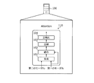
- FIG. 1 is an explanatory diagram showing an embodiment of an output method according to an embodiment.
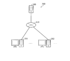
- FIG. 2 is an explanatory diagram showing an example of the information processing system 200.
- FIG. 3 is a block diagram showing a hardware configuration example of the output device 100.
- FIG. 4 is a block diagram showing a functional configuration example of the output device 100.
- FIG. 5 is an explanatory diagram showing a specific example of the Co-Attention Network 500.
- FIG. 6 is an explanatory diagram showing a specific example of the SA layer 600 and a specific example of the TA layer 610.
- FIG. 7 is an explanatory diagram showing a specific example of the image TA layer 501.
- FIG. 8 is an explanatory diagram showing another specific example of the image TA layer 501.
- FIG. 9 is an explanatory diagram showing a comparative example between the image TA layer 501 and the document TA layer 503.
- FIG. 10 is an explanatory diagram showing an example of operation using CAN500.
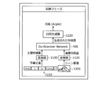
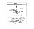
- FIG. 11 is an explanatory diagram (No. 1) showing usage example 1 of the output device 100.
- FIG. 12 is an explanatory diagram (No. 2) showing usage example 1 of the output device 100.
- FIG. 13 is an explanatory diagram (No. 1) showing usage example 2 of the output device 100.
- FIG. 14 is an explanatory diagram (No. 2) showing usage example 2 of the output device 100.
- FIG. 15 is a flowchart showing an example of the learning processing procedure.
- FIG. 16 is a flowchart showing an example of the estimation processing procedure.
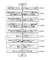
- FIG. 17 is a flowchart showing an example of the attention processing procedure.
- FIG. 1 is an explanatory diagram showing an embodiment of an output method according to an embodiment.
- the output device 100 is a computer for improving the accuracy of a solution when the problem is solved by making it easy to obtain information useful for solving the problem by using a plurality of modal information.
- BERT Bidirectional Encoder Representations from Transformers
- the BERT is formed by stacking the Encoder portions of the Transformer.
- Non-Patent Document 2 can be referred to.
- Non-Patent Document 2 Devlin, Jacob et al. "BERT: Pre-training of Deep Bidirectional Transformers for Language Understanding.” NAACL-HLT (2019).
- BERT is supposed to be applied to a situation where a problem is solved using modal information about a document, and cannot be applied to a situation where a problem is solved using a plurality of modal information. ..
- VideoBERT is specifically an extension of the BERT that can be applied to situations where a problem is solved using modal information about a document and modal information about an image.
- VideoBERT for example, the following Non-Patent Document 3 can be referred to.
- Non-Patent Document 3 Sun, Chen, et al. "Video: A joint model for video and language learning learning.”
- MCAN Modular Co-Attention Network
- Non-Patent Document 4 Yu, Zhou, et al. "Deep Modular Co-Attention Network for Visual Question Answering.” Proceedings of the IEEE Conference on Computer Vision and Pattern Recognition 2019.
- ViLBERT Vision-and-Language Bidirectional Encoder Representations from Transformers.
- ViLBERT is a vector based on modal information about a document, corrected based on a vector based on modal information about an image, and a vector based on modal information about a document, corrected based on a vector based on modal information about a document. It is a technique to solve the problem by referring to.
- Non-Patent Document 5 Lu, Jiasen, et al. "Vilbert: Preprinting task-agnostic visual representations for vision-and-language tags.”
- the accuracy of the solution when solving the problem using a plurality of modal information may be poor.
- the weighting sum of the values obtained from the vector based on the modal information about the document is simply added to the vector based on the modal information about the image by Attention, so that the problem can be solved.
- the accuracy of the solution when solving the problem tends to deteriorate.
- VideoBERT when solving a problem, modal information about a document and modal information about an image are handled without being explicitly distinguished, so that the accuracy of the solution when solving the problem is poor.
- the output device 100 has, for example, a conversion model 110 that realizes Attention.
- the transformation model includes a generative model 101, a coupling model 102, a compression model 103, and a normalization model 104.
- the output device 100 acquires a vector based on the information of the first modal and a vector based on the information of the second modal.
- Modal means a form of information.
- the first modal and the second modal are different modals.
- the first modal is, for example, an image modal.
- the second modal is, for example, a modal for documents.
- the vector based on the information of the first modal is, for example, a vector expressed according to the first modal.
- a vector based on the information of the first modal is generated, for example, based on the information of the first modal.
- the first modal information is, for example, an image.
- the first modal information-based vector is, for example, an image-based vector.
- the vector based on the information of the second modal is, for example, a vector expressed according to the second modal.
- a vector based on the information of the second modal is generated, for example, based on the information of the second modal.
- the second modal information is, for example, a document.
- the second modal information-based vector is, for example, a document-based vector.
- the output device 100 corrects the vector based on the information of the first modal based on the correlation between the vector based on the information of the first modal and the vector based on the information of the second modal. Generate a vector.
- the output device 100 uses, for example, the generative model 101 to generate a correction vector that corrects the vector based on the first modal information.
- Correlation is expressed by, for example, the similarity between the vector obtained from the vector based on the information of the first modal and the vector obtained from the vector based on the information of the second modal.
- the vector obtained from the vector based on the information of the first modal is, for example, a query.
- the vector obtained from the vector based on the information of the second modal is, for example, a key.
- the similarity is expressed by, for example, the inner product.
- the degree of similarity may be expressed by, for example, the sum of squares of differences.
- the output device 100 combines the generated correction vector with the vector based on the information of the first modal.
- the output device 100 for example, uses the coupling model 102 to couple the generated correction vector to the vector based on the first modal information.
- the output device 100 compresses the vector based on the information of the first modal after the combination according to a predetermined rule.
- the output device 100 uses, for example, a compression model 103 to compress a vector based on the information of the first modal after coupling. Compression involves transformations that do not reduce the number of dimensions.
- the output device 100 performs normalization processing on the vector based on the information of the first modal after compression.
- the output device 100 performs the normalization process using, for example, the normalization model 104.
- a specific example of carrying out the normalization process will be described later with reference to, for example, FIG.
- the output device 100 outputs the vector obtained by the normalization process.
- the output format is, for example, display on a display, print output to a printer, transmission to another computer, or storage in a storage area.
- the output device 100 generates and uses a vector based on the information of the first modal and a vector based on the information of the second modal, which tends to reflect information useful for solving the problem. Can be made possible.
- the output device 100 can improve the accuracy of the subsequent solution when the problem is solved.
- the second modal has a feature that it is a higher hierarchy of the first modal.
- “apple (word)” is a concept that includes a plurality of "apples (images)”.
- the output device 100 can utilize this feature to combine a vector based on the first modal information about the image with a correction vector based on the vector based on the second modal information about the document and then compress it. .. Therefore, the output device 100 can make it difficult for the information useful for solving the problem between the image and the document to be lost and easily reflected in the compressed vector.
- the output device 100 can make available a compressed vector that effectively represents, for example, the features of a real-world image or document that are useful in solving a problem on a computer. As a result, the output device 100 can obtain a useful vector when solving the problem using a plurality of modal information, and can improve the accuracy of the solution when the problem is solved.
- first modal and the second modal are different modals
- the first modal and the second modal may be the same modal.
- FIG. 2 is an explanatory diagram showing an example of the information processing system 200.
- the information processing system 200 includes an output device 100, a client device 201, and a terminal device 202.
- the output device 100 and the client device 201 are connected via a wired or wireless network 210.
- the network 210 is, for example, a LAN (Local Area Network), a WAN (Wide Area Network), the Internet, or the like. Further, in the information processing system 200, the output device 100 and the terminal device 202 are connected via a wired or wireless network 210.
- the output device 100 has a vector based on the information of the first modal and a vector based on the information of the second modal based on the vector based on the information of the second modal, and a vector based on the information of the second modal. It has a Co-Attention Network that generates an integrated vector that integrates with.
- the first modal is, for example, an image modal.
- the second modal is, for example, a modal for documents.
- the Co-Attention Network is formed using, for example, the conversion model 110 shown in FIG.
- the output device 100 updates the Co-Attention Network based on the teacher data.
- the teacher data is, for example, a source for generating a vector based on the information of the first modal as a sample and a vector based on the information of the second modal as a sample. Correspondence information in which the second modal information and the correct answer data are associated with each other.
- the teacher data is input to the output device 100 by the user of the output device 100, for example.
- the correct answer data indicates, for example, the correct answer when the problem is solved. For example, if the first modal is a modal about an image, the information in the first modal is an image. For example, if the second modal is a modal about a document, the information in the second modal is a document.
- the output device 100 obtains, for example, a document of teacher data which is obtained by generating a vector based on the information of the first modal from an image of teacher data which is information of the first modal and becomes information of the second modal. Obtained from by generating a vector based on the information of the second modal. Then, the output device 100 uses an error back propagation or the like based on the vector based on the acquired first modal information, the vector based on the acquired second modal information, and the correct answer data of the teacher data, and causes Co. -Update the Attention Network. The output device 100 may update the Co-Attention Network by a learning method other than error back propagation.
- the output device 100 acquires a vector based on the information of the first modal and a vector based on the information of the second modal. Then, the output device 100 uses Co-Attention Network to generate an integrated vector based on the vector based on the acquired first modal information and the vector based on the acquired second modal information. Solve the problem based on the generated integration vector. After that, the output device 100 transmits the result of solving the problem to the client device 201.
- the output device 100 acquires, for example, a vector based on the first modal information input to the output device 100 by the user of the output device 100. Further, the output device 100 may acquire a vector based on the first modal information by receiving the vector from the client device 201 or the terminal device 202. Further, the output device 100 receives, for example, the information of the first modal from the client device 201 or the terminal device 202, and generates a vector based on the information of the first modal from the received information of the first modal. It may be acquired by.
- the output device 100 acquires, for example, a vector based on the second modal information input to the output device 100 by the user of the output device 100. Further, the output device 100 may acquire a vector based on the second modal information by receiving the vector from the client device 201 or the terminal device 202. Further, the output device 100 receives, for example, the information of the second modal from the client device 201 or the terminal device 202, and generates a vector based on the information of the second modal from the received information of the second modal. It may be acquired by.
- the output device 100 uses Co-Attention Network to generate an integrated vector based on the vector based on the acquired first modal information and the vector based on the acquired second modal information. Solve the problem based on the generated integration vector. After that, the output device 100 transmits the result of solving the problem to the client device 201.
- the output device 100 is, for example, a server, a PC (Personal Computer), or the like.
- the client device 201 is a computer capable of communicating with the output device 100.
- the client device 201 may transmit, for example, a vector based on the information of the first modal to the output device 100. Further, the client device 201 may transmit, for example, the first modal information to the output device 100.
- the client device 201 may transmit, for example, a vector based on the second modal information to the output device 100. Further, the client device 201 may transmit, for example, second modal information to the output device 100.
- the client device 201 receives and outputs the result of solving the problem by the output device 100.
- the output format is, for example, display on a display, print output to a printer, transmission to another computer, or storage in a storage area.
- the client device 201 is, for example, a PC, a tablet terminal, a smartphone, or the like.
- the terminal device 202 is a computer capable of communicating with the output device 100.
- the terminal device 202 may transmit, for example, a vector based on the information of the first modal to the output device 100. Further, the terminal device 202 may transmit, for example, the first modal information to the output device 100.
- the terminal device 202 may transmit, for example, a vector based on the information of the second modal to the output device 100. Further, the terminal device 202 may transmit, for example, second modal information to the output device 100.
- the terminal device 202 is, for example, a PC, a tablet terminal, a smartphone, an electronic device, an IoT device, a sensor device, or the like. Specifically, the terminal device 202 may be a surveillance camera.
- the output device 100 updates the Co-Attention Network and solves the problem by using the Co-Attention Network
- another computer may update the Co-Attention Network, and the output device 100 may solve the problem using the Co-Attention Network received from the other computer.
- the output device 100 may update the Co-Attention Network and provide it to another computer, and the other computer may solve the problem by using the Co-Attention Network.
- the teacher data is of the information of the first modal from which the vector based on the information of the first modal is generated and the information of the second modal from which the teacher data is generated from the information of the second modal.
- the case where the corresponding information is associated with the information and the correct answer data has been described, but the present invention is not limited to this.
- the teacher data is correspondence information in which the vector based on the information of the first modal as a sample, the vector based on the information of the second modal as a sample, and the correct answer data are associated with each other. Good.
- the output device 100 is a device different from the client device 201 and the terminal device 202 has been described, but the present invention is not limited to this.
- the output device 100 may be integrated with the client device 201.
- the output device 100 may be integrated with the terminal device 202.
- the output device 100 realizes the Co-Attention Network in terms of software has been described, but the present invention is not limited to this.
- the output device 100 may realize the Co-Attention Network electronically.
- the output device 100 stores an image and a document that serves as a question about the image.
- the question text is, for example, "what is cut in the image”. Then, the output device 100 solves the problem of estimating the answer sentence to the question sentence based on the image and the document.
- the output device 100 estimates, for example, an answer sentence to a question sentence about what is cut in the image based on the image and the document, and transmits the answer sentence to the client device 201.
- the terminal device 202 is a surveillance camera, and an image of the target is transmitted to the output device 100.
- the object is specifically the appearance of the fitting room.
- the output device 100 stores a document that serves as an explanatory text about the target.
- the explanation is an explanation that the curtain of the fitting room tends to be closed while the person is using the fitting room.
- the output device 100 solves the problem of determining the degree of risk based on the image and the document.
- the degree of risk is, for example, an index value indicating the high possibility that a person who has not completed evacuation remains in the fitting room.
- the output device 100 determines, for example, the degree of risk indicating the high possibility that a person who has not completed evacuation remains in the fitting room in the event of a disaster.
- the output device 100 stores an image forming a moving image and a document serving as an explanatory text about the image.
- the moving image is, for example, a moving image showing the state of cooking.
- the explanation is specifically an explanation about the cooking procedure.
- the output device 100 solves the problem of determining the degree of risk based on the image and the document.
- the degree of risk is, for example, an index value indicating the high degree of risk during cooking.
- the output device 100 determines, for example, a degree of risk indicating a high degree of risk during cooking.
- FIG. 3 is a block diagram showing a hardware configuration example of the output device 100.
- the output device 100 includes a CPU (Central Processing Unit) 301, a memory 302, a network I / F (Interface) 303, a recording medium I / F 304, and a recording medium 305. Further, each component is connected by a bus 300.
- the CPU 301 controls the entire output device 100.
- the memory 302 includes, for example, a ROM (Read Only Memory), a RAM (Random Access Memory), a flash ROM, and the like. Specifically, for example, a flash ROM or ROM stores various programs, and RAM is used as a work area of CPU 301. The program stored in the memory 302 is loaded into the CPU 301 to cause the CPU 301 to execute the coded process.
- the network I / F 303 is connected to the network 210 through a communication line, and is connected to another computer via the network 210. Then, the network I / F 303 controls the internal interface with the network 210 and controls the input / output of data from another computer.
- the network I / F 303 is, for example, a modem or a LAN adapter.
- the recording medium I / F 304 controls data read / write to the recording medium 305 according to the control of the CPU 301.
- the recording medium I / F 304 is, for example, a disk drive, an SSD (Solid State Drive), a USB (Universal Serial Bus) port, or the like.
- the recording medium 305 is a non-volatile memory that stores data written under the control of the recording medium I / F 304.
- the recording medium 305 is, for example, a disk, a semiconductor memory, a USB memory, or the like.
- the recording medium 305 may be detachable from the output device 100.
- the output device 100 may include, for example, a keyboard, a mouse, a display, a printer, a scanner, a microphone, a speaker, and the like, in addition to the above-described components. Further, the output device 100 may have a plurality of recording media I / F 304 and recording media 305. Further, the output device 100 does not have to have the recording medium I / F 304 or the recording medium 305.
- the hardware configuration example of the client device 201 is specifically the same as the hardware configuration example of the output device 100 shown in FIG. 3, and thus the description thereof will be omitted.
- the hardware configuration example of the terminal device 202 is specifically the same as the hardware configuration example of the output device 100 shown in FIG. 3, and thus the description thereof will be omitted.
- FIG. 4 is a block diagram showing a functional configuration example of the output device 100.
- the output device 100 includes a storage unit 400, an acquisition unit 401, a generation unit 402, a coupling unit 403, a conversion unit 404, a normalization unit 405, and an output unit 406.
- the storage unit 400 is realized by, for example, a storage area such as the memory 302 or the recording medium 305 shown in FIG.
- a storage area such as the memory 302 or the recording medium 305 shown in FIG.
- the storage unit 400 may be included in a device different from the output device 100, and the stored contents of the storage unit 400 may be referred to by the output device 100.
- the acquisition unit 401 to the output unit 406 function as an example of the control unit.
- the acquisition unit 401 to the output unit 406 may be, for example, by causing the CPU 301 to execute a program stored in a storage area such as the memory 302 or the recording medium 305 shown in FIG. 3, or the network I / F 303. To realize the function.
- the processing result of each functional unit is stored in a storage area such as the memory 302 or the recording medium 305 shown in FIG. 3, for example.
- the storage unit 400 stores various information referred to or updated in the processing of each functional unit.
- the storage unit 400 realizes the attachment, corrects the vector based on the information of the first modal based on the vector based on the information of the second modal, and outputs the vector based on the information of the first modal after correction.
- the first modal is a modal related to images
- the second modal is a modal related to documents.
- the first modal is an image modal
- the second modal is an audio modal.
- the first modal is a modal for a document in a first language
- the second modal is a modal for a document in a second language.
- the first modal may be the same as the second modal.
- the acquisition unit 401 acquires various information used for processing of each functional unit.
- the acquisition unit 401 stores various acquired information in the storage unit 400 or outputs it to each function unit. Further, the acquisition unit 401 may output various information stored in the storage unit 400 to each function unit.
- the acquisition unit 401 acquires various information based on, for example, a user's operation input.
- the acquisition unit 401 may receive various information from a device different from the output device 100, for example.
- the acquisition unit 401 acquires a vector based on the information of the first modal and a vector based on the information of the second modal.
- the acquisition unit 401 for example, is a second modal information source for generating a vector based on the first modal information by the user and a second modal source for generating a vector based on the second modal information. Accepts input with modal information. Then, the acquisition unit 401 generates a vector based on the information of the first modal and a vector based on the information of the second modal based on various input information.
- the acquisition unit 401 acquires an image as the information of the first modal, and generates a feature quantity vector related to the acquired image as a vector based on the information of the first modal.
- the feature amount vector related to the image is, for example, an arrangement of the feature amount vectors for each object appearing in the image.
- the acquisition unit 401 specifically acquires the document as the information of the second modal, and generates the feature quantity vector related to the acquired document as the vector based on the information of the second modal.
- the feature vector related to the document is, for example, an arrangement of the feature vectors for each word included in the document.
- the acquisition unit 401 of the first modal information that is the source of generating the vector based on the information of the first modal and the second modal that is the source of generating the vector based on the information of the second modal.
- Information may be received from the client device 201 or the terminal device 202. Then, the acquisition unit 401 generates a vector based on the information of the first modal and a vector based on the information of the second modal based on the various acquired information.
- the acquisition unit 401 acquires an image as the information of the first modal, and generates a feature quantity vector related to the acquired image as a vector based on the information of the first modal.
- the feature amount vector related to the image is, for example, an arrangement of the feature amount vectors for each object appearing in the image.
- the acquisition unit 401 specifically acquires the document as the information of the second modal, and generates the feature quantity vector related to the acquired document as the vector based on the information of the second modal.
- the feature vector related to the document is, for example, an arrangement of the feature vectors for each word included in the document.
- the acquisition unit 401 receives, for example, the input of the vector based on the information of the first modal and the vector based on the information of the second modal by the user, so that the vector based on the information of the first modal and the vector based on the information of the first modal are received. You may get a vector based on the information of the second modal.
- the acquisition unit 401 may acquire, for example, a vector based on the information of the first modal and a vector based on the information of the second modal by receiving from the client device 201 or the terminal device 202.
- the acquisition unit 401 may accept a start trigger to start processing of any of the functional units.
- the start trigger is, for example, that there is a predetermined operation input by the user.
- the start trigger may be, for example, the receipt of predetermined information from another computer.
- the start trigger may be, for example, that any functional unit outputs predetermined information.
- the acquisition unit 401 receives, for example, the acquisition of the vector based on the information of the first modal and the vector based on the information of the second modal as a start trigger for starting the processing of each functional unit.
- the generation unit 402 generates a correction vector that corrects the vector based on the information of the first modal based on the correlation between the vector based on the information of the first modal and the vector based on the information of the second modal.
- Correlation is expressed, for example, by the degree of similarity between a vector obtained from a vector based on the information of the first modal and a vector obtained from a vector based on the information of the second modal.
- the vector obtained from the vector based on the information of the first modal is, for example, a query.
- the vector obtained from the vector based on the information of the second modal is, for example, a key.
- the similarity is expressed by, for example, the inner product.
- the degree of similarity may be expressed by, for example, the sum of squares of differences.
- the generation unit 402 generates a correction vector based on, for example, the inner product of the vector obtained from the vector based on the information of the first modal and the vector obtained from the vector based on the information of the second modal.
- the generation unit 402 of the first modal is based on the inner product of the query obtained from the vector based on the information of the first modal and the key obtained from the vector based on the information of the second modal.
- the generation unit 402 obtains modal information about the image based on the inner product of the query obtained from the vector based on the modal information about the image and the key obtained from the vector based on the modal information about the document. Generate a correction vector that corrects the underlying vector.
- an example of generating the correction vector is shown in, for example, an operation example described later with reference to FIG. 7.
- the generation unit 402 strongly reflects the component of the vector based on the information of the second modal that is relatively related to the vector based on the information of the first modal to the vector based on the information of the first modal. As such, it is possible to generate a correction vector that can correct the vector based on the information of the first modal.
- the coupling unit 403 combines the generated correction vector with the vector based on the first modal information.
- the coupling unit 403, for example, does not add the correction vector to the vector based on the information of the first modal, but couples it before or after the first modal.
- the connection portion 403 is made so that the information useful for solving the problem, which is the vector based on the information of the first modal and the vector based on the information of the second modal, is hard to be lost and easily reflected.
- Vectors based on modal information can be processed.
- the conversion unit 404 compresses the vector based on the information of the first modal after the combination according to a predetermined rule. Predetermined rules are automatically set by learning, for example.
- the transforming unit 404 uses, for example, a multi-layer neural network to compress a vector based on the information of the first modal after coupling. As a result, the conversion unit 404 can convert the number of dimensions of the vector based on the information of the first modal after the combination into a number of dimensions that is easy to handle.
- the normalization unit 405 performs normalization processing on the vector based on the information of the first modal after compression.
- the normalization unit 405 normalizes, for example, the sum of the vector based on the information of the first modal and the correction vector, and the vector obtained by the normalization and the vector based on the information of the first modal after compression. Normalize the sum of.
- the normalization unit 405 is useful for solving the problem because the information useful for solving the problem among the vector based on the information of the first modal and the vector based on the information of the second modal is efficiently reflected. Vector can be obtained.
- the normalization unit 405 normalizes, for example, the sum of the vector based on the information of the first modal after combining and the vector based on the information of the first modal after compression. As a result, the normalization unit 405 is useful for solving the problem because the information useful for solving the problem among the vector based on the information of the first modal and the vector based on the information of the second modal is efficiently reflected. Vector can be obtained.
- the output unit 406 outputs the processing result of any of the functional units.
- the output format is, for example, display on a display, print output to a printer, transmission to an external device by the network I / F 303, or storage in a storage area such as a memory 302 or a recording medium 305.
- the output unit 406 can notify the user of the processing result of each functional unit, and the convenience of the output device 100 can be improved.
- the output unit 406 outputs the vector obtained by the normalization process. As a result, the output unit 406 can realize the Attention by using the vector obtained by the normalization process. Then, the output unit 406 can realize Co-Attention Network by Attention.
- the output unit 406 can output the vector obtained by the normalization process, which is useful for solving the problem, by Attention, for example. Therefore, the output unit 406 can make the Co-Attention Network learnable so as to be useful for solving the problem. Further, the output unit 406 can improve the accuracy of the solution when the problem is solved.
- FIG. 5 is an explanatory diagram showing a specific example of Co-Attention Network 500.
- Co-Attention Network 500 may be referred to as "CAN500”.
- the target attention may be expressed as "TA”.
- SA self-attention
- the CAN 500 has an image TA layer 501, an image SA layer 502, a document TA layer 503, a document SA layer 504, a binding layer 505, and an integrated SA layer 506.
- the CAN 500 outputs the vector Z T in response to the input of the feature amount vector L related to the document and the feature amount vector I related to the image.
- the feature quantity vector L related to the document is, for example, an arrangement of M feature quantity vectors related to the document.
- the M feature vector is, for example, a feature vector indicating M words included in the document.
- the feature amount vector I related to the image is, for example, an arrangement of N feature amount vectors related to the image.
- the N feature vector is, for example, a feature vector indicating N objects in the image.
- the image TA layer 501 accepts inputs of the feature amount vector I related to the image and the feature amount vector L related to the document.
- the image TA layer 501 corrects the feature vector I for the image based on the query obtained from the feature vector I for the image and the keys and values obtained from the feature vector L for the document.
- the image TA layer 501 outputs the feature amount vector I related to the corrected image to the image SA layer 502. Specific examples of the image TA layer 501 will be described later with reference to, for example, FIGS. 7 and 8.
- the image SA layer 502 accepts the input of the feature amount vector I related to the corrected image.
- the image SA layer 502 further corrects the feature vector I related to the corrected image based on the query, key, and value obtained from the feature vector I related to the corrected image, and generates a new feature vector Z I. And output to the bond layer 505.
- a specific example of the SA layer that realizes the image SA layer 502 will be described later with reference to, for example, FIG.
- the document TA layer 503 accepts inputs of the feature amount vector L related to the document and the feature amount vector I related to the image.
- the document TA layer 503 corrects the feature vector L related to the document based on the query obtained from the feature vector L related to the document and the keys and values obtained from the feature vector I related to the image.
- the document TA layer 503 outputs the feature amount vector L related to the corrected document to the document SA layer 504.
- a specific example of the TA layer that realizes the document TA layer 503 will be described later with reference to, for example, FIG.
- the document SA layer 504 accepts the input of the feature amount vector L related to the corrected document.
- the document SA layer 504 further corrects the feature vector L related to the corrected document based on the query, key, and value obtained from the feature vector L related to the corrected document, and generates a new feature vector Z L. And output.
- a specific example of the SA layer that realizes the document SA layer 504 will be described later with reference to, for example, FIG.
- the coupling layer 505 receives inputs of the aggregation vector H, the feature amount vector Z I, and the feature amount vector Z L.
- the coupling layer 505 combines the aggregation vector H, the feature quantity vector Z I, and the feature quantity vector Z L to generate the coupling vector C, and outputs the coupling vector C to the integrated SA layer 506.
- the integrated SA layer 506 accepts the input of the coupling vector C.
- the integrated SA layer 506 corrects the coupling vector C based on the query, key, and value obtained from the coupling vector C, and generates and outputs the feature vector Z T.
- the feature vector Z T includes an aggregate vector Z H , an integrated feature vector Z 1 to Z M related to the document, and an integrated feature vector Z M + 1 to Z M + N related to the image.
- the output device 100 can generate a feature vector Z T including an aggregate vector Z H , which is useful from the viewpoint of improving the accuracy of the solution when the problem is solved, and make it referenceable. Therefore, the output device 100 can improve the accuracy of the solution when the problem is solved.
- the output device 100 can further improve the accuracy of the solution when the problem is solved.
- the output device 100 uses, for example, the output of the image SA layer 502 and the output of the document SA layer 504 in solving the problem.
- FIG. 6 shifts to a specific example of the SA layer 600 that realizes the image SA layer 502 forming the CAN 500, the document SA layer 504, the integrated SA layer 506, and the like, and the document TA layer 503 forming the CAN 500.
- a specific example of the TA layer 610 that realizes the above will be described.
- Specific examples of the image TA layer 501 forming the CAN 500 will be described later with reference to FIG.
- FIG. 6 is an explanatory diagram showing a specific example of the SA layer 600 and a specific example of the TA layer 610.
- Multi-Head Attention may be referred to as "MHA”.
- Add & Norm may be referred to as "A & N”.
- Feed Forward may be described as "FF”.
- the SA layer 600 has an MHA layer 601, an A & N layer 602, an FF layer 603, and an A & N layer 604.
- the MHA layer 601 generates a correction vector R that corrects the input vector X based on the query Q, the key K, and the value V obtained from the input vector X, and outputs the correction vector R to the A & N layer 602.
- the MHA layer 601 divides the input vector X into Head vectors for processing. Head is a natural number of 1 or more.
- the A & N layer 602 is normalized after adding the input vector X and the correction vector R, and the normalized vector is output to the FF layer 603 and the A & N layer 604.
- the FF layer 603 compresses the normalized vector and outputs the compressed vector to the A & N layer 604.
- the A & N layer 604 adds the normalized vector and the compressed vector, normalizes the vector, generates an output vector Z, and outputs the output vector Z.
- the TA layer 610 has an MHA layer 611, an A & N layer 612, an FF layer 613, and an A & N layer 614.
- the MHA layer 611 generates a correction vector R that corrects the input vector X based on the query Q obtained from the input vector X and the key K and the value V obtained from the input vector Y, and outputs the correction vector R to the A & N layer 612. .
- the A & N layer 612 adds the input vector X and the correction vector R and normalizes them, and outputs the normalized vector to the FF layer 613 and the A & N layer 614.
- the FF layer 613 compresses the normalized vector and outputs the compressed vector to the A & N layer 614.
- the A & N layer 614 adds and normalizes the normalized vector and the compressed vector, generates an output vector Z, and outputs the output vector Z.
- the above-mentioned MHA layer 601 and MHA layer 611 are formed by the number of Attention layers 620 corresponding to the number of Heads.
- the Attention layer 620 has a MatMul layer 621, a Scale layer 622, a Mask layer 623, a SoftMax layer 624, and a MatMul layer 625.
- MatMul layer 621 calculates the inner product of query Q and key K and sets it in Score.
- the Scale layer 622 divides the entire Score by a constant a and updates it.
- the Mask layer 623 may mask the updated Score.
- the SoftMax layer 624 normalizes the updated Score and sets it to Att.
- the MatMul layer 625 calculates the inner product of Att and the value V and sets it in the correction vector R.
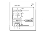
- FIG. 7 is an explanatory diagram showing a specific example of the image TA layer 501.
- the image TA layer 501 includes an MHA layer 701, an A & N layer 702, a Con layer 703, an FF layer 704, and an A & N layer 705.
- the MHA layer 701 generates a correction vector R that corrects the input vector X based on the query Q obtained from the input vector X and the key K and the value V obtained from the input vector Y, and the A & N layer 702 and the Con layer. Output to 703.
- the A & N layer 702 adds the input vector X and the correction vector R, normalizes the input vector X, and outputs the normalized vector to the A & N layer 705.
- the Con layer 703 combines the input vector X and the correction vector R, and outputs the combined vector to the FF layer 704.
- the FF layer 704 compresses the coupling vector and outputs the compressed vector to the A & N layer 705.
- the A & N layer 705 adds the normalized vector and the compressed vector, normalizes the vector, and outputs the output vector obtained by the normalization.
- FIG. 8 is an explanatory diagram showing another specific example of the image TA layer 501.
- the image TA layer 501 includes an MHA layer 801, a Con layer 802, an FF layer 803, and an A & N layer 804.
- the MHA layer 801 generates a correction vector R for correcting the input vector X based on the query Q obtained from the input vector X and the key K and the value V obtained from the input vector Y, and outputs the correction vector R to the Con layer 802. .
- the Con layer 802 combines the input vector X and the correction vector R, and outputs the combined vector to the FF layer 803 and the A & N layer 804.
- the FF layer 803 compresses the coupling vector and outputs the compressed vector to the A & N layer 804.
- the A & N layer 804 adds the combined vector and the compressed vector, normalizes them, and outputs the output vector obtained by the normalization.
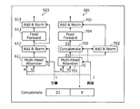
- FIG. 9 is an explanatory diagram showing a comparative example between the image TA layer 501 and the document TA layer 503.
- the image TA layer 501 and the document TA layer 503 receive inputs of the feature amount vector L related to the document and the feature amount vector I related to the image.
- the image TA layer 501 and the document TA layer 503 handle the feature amount vector L related to the document and the feature amount vector I related to the image by different methods, respectively.
- the image TA layer 501 generates a new feature vector Z I 2 by combining the vector Z I 1 with the feature vector I related to the image.
- the document TA layer 503 generates a new feature amount vector Z L2 by adding the vector Z L1 to the feature amount vector L related to the document.
- the output device 100 can handle the feature amount vector L related to the document and the feature amount vector I related to the image, which have different properties, differently.
- the output device 100 can make it difficult for the information useful for solving the problem among the feature amount vector L related to the document and the feature amount vector I related to the image to be lost.
- the output device 100 can obtain a vector useful for solving the problem by using the information of a plurality of modals, and can improve the accuracy of the solution when the problem is solved.
- the image TA layer 501 is formed as in the specific examples shown in FIGS. 7 and 8 has been described, but the present invention is not limited to this.
- at least one of the image SA layer 502, the document TA layer 503, the document SA layer 504, and the integrated SA layer 506 may be formed in the same manner as in the specific examples shown in FIGS. 7 and 8. Good.
- FIG. 10 is an explanatory diagram showing an example of operation using CAN500.
- the output device 100 acquires the document 1000 and the image 1010.
- the output device 100 tokenizes the document 1000, vectorizes the token set 1001, generates a feature amount vector 1002 related to the document 1000, and inputs the feature amount vector 1002 to the CAN 500.
- the output device 100 detects an object from the image 1010, vectorizes a set 1011 of partial images for each object, generates a feature amount vector 1012 related to the image 1010, and inputs the feature amount vector 1012 to the CAN 500.
- the output device 100 acquires the feature amount vector Z T from the CAN 500, and inputs the aggregate vector Z H included in the feature amount vector Z T to the risk estimator 1030.
- the output device 100 acquires the estimation result No. from the risk estimator 1030. Whether Thereby, the output apparatus 100 uses the aggregated vector Z H the characteristics of the image and the document is reflected, the risk estimator 1030 can be estimated whether it is dangerous or dangerous Can be estimated accurately.
- FIG. 11 and 12 are explanatory views showing a usage example 1 of the output device 100.
- the output device 100 performs a learning phase and learns the CAN 500.
- the output device 100 acquires, for example, an image 1100 in which some scene is captured and a document 1110 as a subtitle corresponding to the image 1100.
- Image 1100 captures, for example, a scene of cutting an apple.
- the output device 100 converts the image 1100 into a feature amount vector by the converter 1120 and inputs it to the CAN 500. Further, the output device 100 masks the word apple of the document 1110, converts it into a feature amount vector by the converter 1130, and inputs it to the CAN 500.
- the output device 100 inputs the feature amount vector generated by the CAN 500 into the classifier 1140, acquires the result of predicting the masked word, and calculates the error from the correct answer "apple" of the masked word.
- the output device 100 learns the CAN 500 by error back propagation based on the calculated error. Further, the output device 100 may learn the converters 1120, 1130 and the classifier 1140 by backpropagation of errors.
- the output device 100 updates the CAN 500, the converters 1120, 1130, and the classifier 1140 so as to be useful from the viewpoint of estimating the word in consideration of the context of the image 1100 and the document 1110 which is the subtitle. Can be done.
- the description proceeds to FIG.
- the output device 100 carries out a test phase, and uses the learned converters 1120 and 1130 and the learned CAN500 to generate and output an answer.
- the output device 100 acquires, for example, an image 1200 in which some scene is captured and a document 1210 as a question sentence corresponding to the image 1200.
- Image 1200 captures, for example, a scene of cutting an apple.
- the output device 100 converts the image 1200 into a feature amount vector by the converter 1120 and inputs it to the CAN 500. Further, the output device 100 converts the document 1210 into a feature amount vector by the converter 1130 and inputs it to the CAN 500. The output device 100 inputs the feature amount vector generated by the CAN 500 into the answer generator 1220, acquires a word to be an answer, and outputs the vector. As a result, the output device 100 can accurately estimate the word to be answered in consideration of the image 1200 and the context of the document 1210 which is a question sentence.
- FIG. 13 and 14 are explanatory views showing a usage example 2 of the output device 100.
- the output device 100 performs a learning phase and learns the CAN 500.
- the output device 100 acquires, for example, an image 1300 in which some scene is captured and a document 1310 as a subtitle corresponding to the image 1300.
- Image 1300 shows, for example, a scene of cutting an apple.
- the output device 100 converts the image 1300 into a feature amount vector by the converter 1320 and inputs it to the CAN 500. Further, the output device 100 masks the word apple of the document 1310, converts it into a feature amount vector by the converter 1330, and inputs it to the CAN 500.
- the output device 100 inputs the feature amount vector generated by the CAN 500 into the classifier 1340, acquires the result of predicting the risk level of the scene shown in the image, and calculates the error from the correct answer of the risk level.
- the output device 100 learns the CAN 500 by error back propagation based on the calculated error. Further, the output device 100 learns the converters 1320 and 1330 and the classifier 1340 by backpropagation of errors.
- the output device 100 updates the CAN 500, the converters 1120, 1130, and the classifier 1140 so as to be useful from the viewpoint of predicting the degree of risk in consideration of the image 1300 and the context of the document 1310 which is the subtitle. be able to.
- the description shifts to FIG.
- the output device 100 carries out a test phase, predicts the degree of risk and outputs using the learned converters 1320 and 1330 and the classifier 1340 and the learned CAN500.
- the output device 100 acquires, for example, an image 1400 showing some scene and a document 1410 as an explanatory text corresponding to the image.
- Image 1400 captures, for example, a scene of cutting a thigh.
- the output device 100 converts the image 1400 into a feature amount vector by the converter 1320 and inputs it to the CAN 500. Further, the output device 100 converts the document 1410 into a feature amount vector by the converter 1330 and inputs it to the CAN 500. The output device 100 inputs the feature quantity vector generated by the CAN 500 into the classifier 1340, acquires the degree of risk, and outputs the vector. As a result, the output device 100 can accurately predict the degree of risk in consideration of the image 1400 and the context of the document 1410 as the explanatory text.
- the learning process is realized, for example, by the CPU 301 shown in FIG. 3, a storage area such as a memory 302 or a recording medium 305, and a network I / F 303.
- FIG. 15 is a flowchart showing an example of the learning processing procedure.
- the output device 100 acquires the feature amount vector of the image and the feature amount vector of the document (step S1501).
- the output device 100 uses the image TA layer 501 based on the query generated from the acquired image feature vector and the keys and values generated from the acquired document feature vector to image features.
- the quantity vector is corrected (step S1502).
- the output device 100 corrects the feature amount vector of the image by executing the attention processing described later in FIG.
- the output device 100 further corrects the feature amount vector of the corrected image by using the image SA layer 502 based on the feature amount vector of the corrected image, and newly generates the feature amount vector of the image. (Step S1503).
- the output device 100 uses the document TA layer 503 based on the query generated from the acquired document feature vector and the keys and values generated from the acquired image feature vector, to use the document features.
- the quantity vector is corrected (step S1504).
- the output device 100 further corrects the feature amount vector of the corrected document by using the document SA layer 504 based on the feature amount vector of the corrected document, and newly generates the feature amount vector of the document. (Step S1505).
- the output device 100 initializes the aggregation vector (step S1506). Then, the output device 100 combines the aggregation vector, the feature amount vector of the generated image, and the feature amount vector of the generated document to generate a combined vector (step S1507).
- the output device 100 corrects the coupling vector using the integrated SA layer 506 based on the coupling vector and generates an aggregate vector (step S1508). Then, the output device 100 learns the CAN 500 based on the aggregation vector (step S1509).
- the output device 100 ends the learning process.
- the output device 100 can update the parameters of the CAN 500 so that the accuracy of the solution when the problem is solved is improved.
- the output device 100 may execute the processing in the partial steps of FIG. 15 in a different order.
- the order of the processes of steps S1502 and S1503 and the processes of steps S1504 and S1505 can be exchanged.
- the output device 100 may repeatedly execute the processes of steps S1502 to S1505.
- Estimatiation processing procedure Next, an example of the estimation processing procedure executed by the output device 100 will be described with reference to FIG.
- the estimation process is realized, for example, by the CPU 301 shown in FIG. 3, a storage area such as a memory 302 or a recording medium 305, and a network I / F 303.
- FIG. 16 is a flowchart showing an example of the estimation processing procedure.
- the output device 100 acquires the feature amount vector of the image and the feature amount vector of the document (step S1601).
- the output device 100 uses the image TA layer 501 based on the query generated from the acquired image feature vector and the keys and values generated from the acquired document feature vector to image features.
- the quantity vector is corrected (step S1602).
- the output device 100 corrects the feature amount vector of the image by executing the attention processing described later in FIG.
- the output device 100 further corrects the feature amount vector of the corrected image by using the image SA layer 502 based on the feature amount vector of the corrected image, and newly generates the feature amount vector of the image. (Step S1603).
- the output device 100 uses the document TA layer 503 based on the query generated from the acquired document feature vector and the keys and values generated from the acquired image feature vector, to use the document features.
- the quantity vector is corrected (step S1604).
- the output device 100 further corrects the feature amount vector of the corrected document by using the document SA layer 504 based on the feature amount vector of the corrected document, and newly generates the feature amount vector of the document. (Step S1605).
- the output device 100 initializes the aggregation vector (step S1606). Then, the output device 100 combines the aggregation vector, the feature amount vector of the generated image, and the feature amount vector of the generated document to generate a combined vector (step S1607).
- the output device 100 corrects the coupling vector using the integrated SA layer 506 based on the coupling vector and generates an aggregate vector (step S1608). Then, the output device 100 estimates the situation using the discriminative model based on the aggregation vector (step S1609).
- the output device 100 outputs the estimated situation (step S1610). Then, the output device 100 ends the estimation process. As a result, the output device 100 can improve the accuracy of the solution when the problem is solved by using the CAN 500.
- the output device 100 may execute the processing in a part of the steps of FIG. 16 by changing the order of processing. For example, the order of the processes of steps S1602 and S1603 and the processes of steps S1604 and S1605 can be exchanged. Further, the output device 100 may repeatedly execute the processes of steps S1602 to S1605.
- the attention processing is realized, for example, by the CPU 301 shown in FIG. 3, a storage area such as a memory 302 or a recording medium 305, and a network I / F 303.
- FIG. 17 is a flowchart showing an example of the attention processing procedure.
- the output device 100 acquires the feature amount vector of the image serving as the vector X and the feature amount vector of the document serving as the vector Y (step S1701).
- the output device 100 generates a vector Query from the feature quantity vector of the acquired image (step S1702). Then, the output device 100 generates a vector key and a vector Value from the feature quantity vector of the acquired document (step S1703).
- the output device 100 calculates the inner product of the generated vector Query and the generated vector key (step S1704). Then, the output device 100 generates a vector Att by the softmax of the inner product (step S1705).
- the output device 100 generates a vector R by the inner product of the vector Att and the vector Value (step S1706). Then, the output device 100 generates a vector X'by combining the vector R and the vector X (step S1707).
- the output device 100 compresses the vector X'in the same dimension as the vector X by the multi-layer neural network to generate the vector X "(step S1708), and the output device 100 generates the vector R and the vector X.
- the vector X ” is normalized using and, and the normalized vector is acquired (step S1709).
- the output device 100 outputs the acquired vector after normalization (step S1710). Then, the output device 100 ends the attention processing. As a result, the output device 100 can generate and acquire the normalized vector so that the information useful for solving the problem between the image and the document is hard to be lost.
- the output device 100 may execute by changing the order of processing of some steps in FIG. For example, the order of the process of step S1702 and the process of step S1703 can be exchanged.
- a vector based on the information of the first modal is obtained based on the correlation between the vector based on the information of the first modal and the vector based on the information of the second modal.
- a correction vector to be corrected can be generated.
- the generated correction vector can be combined with the vector based on the first modal information.
- the vector based on the information of the first modal after the combination can be compressed according to a predetermined rule.
- the normalization process can be performed on the vector based on the information of the first modal after compression.
- the vector obtained by the normalization process can be output.
- the output device 100 leaves the vector based on the information of the first modal and the vector based on the information of the second modal, which is useful for solving the problem, and provides a vector useful for solving the problem. It can be obtained, and the accuracy of the solution when solving the problem can be improved.
- a correction vector can be generated based on the inner product of the vector obtained from the vector based on the information of the first modal and the vector obtained from the vector based on the information of the second modal. ..
- the output device 100 can realize attention.
- the output device 100 can obtain a correction vector useful for solving the problem.
- the output device 100 the sum of the vector based on the information of the first modal and the correction vector is normalized, and the vector obtained by the normalization and the vector based on the information of the first modal after compression are combined.
- the sum can be normalized.
- the output device 100 can realize the normalization process.
- the output device 100 it is possible to normalize the sum of the vector based on the information of the first modal after coupling and the vector based on the information of the first modal after compression. As a result, the output device 100 can realize the normalization process.
- a modal related to an image can be adopted as the first modal.
- a document-related modal can be adopted as the second modal.
- the output device 100 can realize the target attention layer. Further, the output device 100 can be made applicable when solving a problem based on an image and a document.
- a modal related to an image can be adopted as the first modal.
- a modal related to voice can be adopted as the second modal.
- the output device 100 can realize the target attention layer. Further, the output device 100 can be made applicable when solving a problem based on an image and a sound.
- the output device 100 as the first modal, the modal related to the document in the first language can be adopted.
- the output device 100 as the second modal, a modal relating to a document in a second language can be adopted.
- the output device 100 can realize the target attention layer. Further, the output device 100 can be made applicable when solving a problem based on two documents in different languages.
- the same modal can be adopted for the first modal and the second modal.
- the output device 100 can realize a self-attention layer. Further, the output device 100 can be made applicable when solving a problem based on different information of the same modal.
- the output method described in this embodiment can be realized by executing a program prepared in advance on a computer such as a PC or a workstation.
- the output program described in this embodiment is recorded on a computer-readable recording medium and executed by being read from the recording medium by the computer.
- the recording medium is a hard disk, a flexible disk, a CD (Compact Disc) -ROM, an MO, a DVD (Digital Any Disc), or the like.
- the output program described in this embodiment may be distributed via a network such as the Internet.
Landscapes
- Engineering & Computer Science (AREA)
- Theoretical Computer Science (AREA)
- Physics & Mathematics (AREA)
- Evolutionary Computation (AREA)
- Software Systems (AREA)
- General Physics & Mathematics (AREA)
- Artificial Intelligence (AREA)
- Computing Systems (AREA)
- Computer Vision & Pattern Recognition (AREA)
- General Health & Medical Sciences (AREA)
- Health & Medical Sciences (AREA)
- Data Mining & Analysis (AREA)
- General Engineering & Computer Science (AREA)
- Medical Informatics (AREA)
- Mathematical Physics (AREA)
- Life Sciences & Earth Sciences (AREA)
- Biophysics (AREA)
- Molecular Biology (AREA)
- Computational Linguistics (AREA)
- Databases & Information Systems (AREA)
- Biomedical Technology (AREA)
- Multimedia (AREA)
- Bioinformatics & Cheminformatics (AREA)
- Bioinformatics & Computational Biology (AREA)
- Evolutionary Biology (AREA)
- Information Retrieval, Db Structures And Fs Structures Therefor (AREA)
- Image Analysis (AREA)
Priority Applications (3)
| Application Number | Priority Date | Filing Date | Title |
|---|---|---|---|
| PCT/JP2019/044770 WO2021095212A1 (ja) | 2019-11-14 | 2019-11-14 | 出力方法、出力プログラム、および出力装置 |
| JP2021555729A JP7207568B2 (ja) | 2019-11-14 | 2019-11-14 | 出力方法、出力プログラム、および出力装置 |
| US17/719,211 US20220237421A1 (en) | 2019-11-14 | 2022-04-12 | Method for outputting, computer-readable recording medium storing output program, and output device |
Applications Claiming Priority (1)
| Application Number | Priority Date | Filing Date | Title |
|---|---|---|---|
| PCT/JP2019/044770 WO2021095212A1 (ja) | 2019-11-14 | 2019-11-14 | 出力方法、出力プログラム、および出力装置 |
Related Child Applications (1)
| Application Number | Title | Priority Date | Filing Date |
|---|---|---|---|
| US17/719,211 Continuation US20220237421A1 (en) | 2019-11-14 | 2022-04-12 | Method for outputting, computer-readable recording medium storing output program, and output device |
Publications (1)
| Publication Number | Publication Date |
|---|---|
| WO2021095212A1 true WO2021095212A1 (ja) | 2021-05-20 |
Family
ID=75911528
Family Applications (1)
| Application Number | Title | Priority Date | Filing Date |
|---|---|---|---|
| PCT/JP2019/044770 Ceased WO2021095212A1 (ja) | 2019-11-14 | 2019-11-14 | 出力方法、出力プログラム、および出力装置 |
Country Status (3)
| Country | Link |
|---|---|
| US (1) | US20220237421A1 (https=) |
| JP (1) | JP7207568B2 (https=) |
| WO (1) | WO2021095212A1 (https=) |
Cited By (1)
| Publication number | Priority date | Publication date | Assignee | Title |
|---|---|---|---|---|
| WO2024184975A1 (ja) * | 2023-03-03 | 2024-09-12 | 日本電信電話株式会社 | 符号化装置、学習方法、及びプログラム |
Family Cites Families (3)
| Publication number | Priority date | Publication date | Assignee | Title |
|---|---|---|---|---|
| CA2670861A1 (en) * | 2006-11-28 | 2008-06-05 | Calgary Scientific Inc. | Texture-based multi-dimensional medical image registration |
| WO2016100816A1 (en) * | 2014-12-19 | 2016-06-23 | United Technologies Corporation | Sensor data fusion for prognostics and health monitoring |
| US11210560B2 (en) * | 2019-10-02 | 2021-12-28 | Mitsubishi Electric Research Laboratories, Inc. | Multi-modal dense correspondence imaging system |
-
2019
- 2019-11-14 WO PCT/JP2019/044770 patent/WO2021095212A1/ja not_active Ceased
- 2019-11-14 JP JP2021555729A patent/JP7207568B2/ja active Active
-
2022
- 2022-04-12 US US17/719,211 patent/US20220237421A1/en active Pending
Non-Patent Citations (2)
| Title |
|---|
| LU, J. S. ET AL., VILBERT: PRETRAINING TASK- AGNOSTIC VISIOLINGUISTIC REPRESENTATIONS FOR VISION-AND-LANGUAGE TASKS, 6 August 2019 (2019-08-06), pages 1 - 11, XP081456681, Retrieved from the Internet <URL:https://arxiv.org/pdf/1908.02265v1.pdf> [retrieved on 20191213] * |
| NGUYEN, D. K. ET AL., IMPROVED FUSION OF VISUAL AND LANGUAGE REPRESENTATIONS BY DENSE SYMMETRIC CO-ATTENTION FOR VISUAL QUESTION ANSWERING, 2018, pages 6087 - 6096, XP033473524, Retrieved from the Internet <URL:http://openaccess.thecvf.com/content_cvpr_2018/html/Nguyen_Improved_Fusion_of_CVPR_2018_paper.html> [retrieved on 20191213] * |
Cited By (1)
| Publication number | Priority date | Publication date | Assignee | Title |
|---|---|---|---|---|
| WO2024184975A1 (ja) * | 2023-03-03 | 2024-09-12 | 日本電信電話株式会社 | 符号化装置、学習方法、及びプログラム |
Also Published As
| Publication number | Publication date |
|---|---|
| JP7207568B2 (ja) | 2023-01-18 |
| US20220237421A1 (en) | 2022-07-28 |
| JPWO2021095212A1 (https=) | 2021-05-20 |
Similar Documents
| Publication | Publication Date | Title |
|---|---|---|
| US10621991B2 (en) | Joint neural network for speaker recognition | |
| US20220237263A1 (en) | Method for outputting, computer-readable recording medium storing output program, and output device | |
| TWI682325B (zh) | 辨識系統及辨識方法 | |
| US7864352B2 (en) | Printer with multimedia server | |
| CN108510982B (zh) | 音频事件检测方法、装置及计算机可读存储介质 | |
| US12452620B2 (en) | Multi-channel speech compression system and method | |
| CN113611308B (zh) | 一种语音识别方法、装置、系统、服务器及存储介质 | |
| EP4231200B1 (en) | Distributed machine learning inference | |
| JPWO2021095211A5 (https=) | ||
| CN118737121B (zh) | 伴随音频生成方法、相关装置和介质 | |
| WO2022160749A1 (zh) | 一种用于语音处理装置的角色分离方法及其语音处理装置 | |
| Xu et al. | Audio-visual wake word spotting system for MISP challenge 2021 | |
| JP7207568B2 (ja) | 出力方法、出力プログラム、および出力装置 | |
| WO2021095213A1 (ja) | 学習方法、学習プログラム、および学習装置 | |
| JPWO2021095212A5 (https=) | ||
| CN115910037B (zh) | 语音信号的提取方法、装置、可读存储介质及电子设备 | |
| JP2005196020A (ja) | 音声処理装置と方法並びにプログラム | |
| CN115881101A (zh) | 一种语音识别模型的训练方法、装置以及处理设备 | |
| CN116089826A (zh) | 基于边缘设备和远端协同的轻量模型优化方法及装置 | |
| WO2023018423A1 (en) | Learning semantic binary embedding for video representations | |
| US20240419731A1 (en) | Knowledge-based audio scene graph | |
| CN121117952A (zh) | 基于大语言模型的多源异构数据统一语义表征方法 | |
| CN118553235A (zh) | 一种多模态智能终端的语音识别方法及系统 | |
| CN120263862A (zh) | 云边数据传输系统的数据传输方法、压缩比计算方法及相关设备 | |
| DeCamp | Headlock: Wide-range head pose estimation for low resolution video |
Legal Events
| Date | Code | Title | Description |
|---|---|---|---|
| 121 | Ep: the epo has been informed by wipo that ep was designated in this application |
Ref document number: 19952648 Country of ref document: EP Kind code of ref document: A1 |
|
| ENP | Entry into the national phase |
Ref document number: 2021555729 Country of ref document: JP Kind code of ref document: A |
|
| NENP | Non-entry into the national phase |
Ref country code: DE |
|
| 122 | Ep: pct application non-entry in european phase |
Ref document number: 19952648 Country of ref document: EP Kind code of ref document: A1 |