WO2021095138A1 - 方法、システム及び変換装置 - Google Patents
方法、システム及び変換装置 Download PDFInfo
- Publication number
- WO2021095138A1 WO2021095138A1 PCT/JP2019/044409 JP2019044409W WO2021095138A1 WO 2021095138 A1 WO2021095138 A1 WO 2021095138A1 JP 2019044409 W JP2019044409 W JP 2019044409W WO 2021095138 A1 WO2021095138 A1 WO 2021095138A1
- Authority
- WO
- WIPO (PCT)
- Prior art keywords
- communication
- communication flow
- packet
- traffic
- flows
- Prior art date
- Legal status (The legal status is an assumption and is not a legal conclusion. Google has not performed a legal analysis and makes no representation as to the accuracy of the status listed.)
- Ceased
Links
Images


Classifications
-
- H—ELECTRICITY
- H04—ELECTRIC COMMUNICATION TECHNIQUE
- H04L—TRANSMISSION OF DIGITAL INFORMATION, e.g. TELEGRAPHIC COMMUNICATION
- H04L47/00—Traffic control in data switching networks
- H04L47/10—Flow control; Congestion control
- H04L47/12—Avoiding congestion; Recovering from congestion
- H04L47/125—Avoiding congestion; Recovering from congestion by balancing the load, e.g. traffic engineering
-
- H—ELECTRICITY
- H04—ELECTRIC COMMUNICATION TECHNIQUE
- H04L—TRANSMISSION OF DIGITAL INFORMATION, e.g. TELEGRAPHIC COMMUNICATION
- H04L47/00—Traffic control in data switching networks
- H04L47/10—Flow control; Congestion control
- H04L47/24—Traffic characterised by specific attributes, e.g. priority or QoS
- H04L47/2491—Mapping quality of service [QoS] requirements between different networks
-
- H—ELECTRICITY
- H04—ELECTRIC COMMUNICATION TECHNIQUE
- H04L—TRANSMISSION OF DIGITAL INFORMATION, e.g. TELEGRAPHIC COMMUNICATION
- H04L63/00—Network architectures or network communication protocols for network security
- H04L63/14—Network architectures or network communication protocols for network security for detecting or protecting against malicious traffic
- H04L63/1408—Network architectures or network communication protocols for network security for detecting or protecting against malicious traffic by monitoring network traffic
-
- H—ELECTRICITY
- H04—ELECTRIC COMMUNICATION TECHNIQUE
- H04L—TRANSMISSION OF DIGITAL INFORMATION, e.g. TELEGRAPHIC COMMUNICATION
- H04L63/00—Network architectures or network communication protocols for network security
- H04L63/14—Network architectures or network communication protocols for network security for detecting or protecting against malicious traffic
- H04L63/1441—Countermeasures against malicious traffic
- H04L63/1475—Passive attacks, e.g. eavesdropping or listening without modification of the traffic monitored
-
- H—ELECTRICITY
- H04—ELECTRIC COMMUNICATION TECHNIQUE
- H04W—WIRELESS COMMUNICATION NETWORKS
- H04W28/00—Network traffic management; Network resource management
- H04W28/16—Central resource management; Negotiation of resources or communication parameters, e.g. negotiating bandwidth or QoS [Quality of Service]
- H04W28/18—Negotiating wireless communication parameters
Definitions
- This disclosure relates to methods, systems and converters.
- IoT Internet of Things
- Non-Patent Document 1 describes a method of inducing erroneous estimation by converting the statistical characteristics of traffic against an attack that estimates a Web access destination from the characteristics of traffic. Specifically, according to Non-Patent Document 1, by adding a dummy packet, traffic is increased and the throughput characteristics are converted.
- Non-Patent Document 1 by adding a dummy packet to an attacker who estimates a Web access destination from the characteristics of traffic, the traffic is increased and the throughput characteristics are converted.
- communication traffic that requires real-time performance is generally accompanied by high-frequency communication, it is considered that the increase in traffic is not effective.
- the communication traffic is accompanied by more frequent communication, and is ultimately regarded as a communication traffic that requires real-time performance. Therefore, adding a dummy packet is not effective for an attacker who wants to estimate a service that requires real-time performance.
- An object of the present disclosure is to provide methods, systems and converters that allow the analysis of traffic traffic to mislead the estimation of the source.
- a method is to divide the original communication flow from the source device into a plurality of communication flows that match the selected traffic characteristics, and to divide the plurality of communication flows into the above-mentioned plurality of communication flows. It includes transmitting a packet belonging to each of the plurality of communication flows to the restoration device that restores the original communication flow.
- a system includes a conversion device and a restoration device, wherein the conversion device adapts the original communication flow from the source device to a plurality of communication flows that match selected traffic features.
- the packet belonging to each of the plurality of communication flows is transmitted to the restoration device, the restoration device receives the packet belonging to each of the plurality of communication flows, and the plurality of communication flows are transmitted to the original. Restore to the communication flow of.
- the conversion device includes a conversion unit that divides the original communication flow from the source device into a plurality of communication flows that match the selected traffic characteristics, and the above-mentioned plurality of communication flows.
- a transmission unit that transmits packets belonging to each of the plurality of communication flows is provided to the restoration device that restores the communication flow.
- An example of the schematic configuration of the system according to the first embodiment is shown. It is a block diagram which shows the example of the schematic functional structure of the conversion apparatus which concerns on 1st Embodiment. It is a block diagram which shows the example of the schematic hardware structure of the conversion apparatus which concerns on 1st Embodiment. It is a block diagram which shows the example of the schematic functional structure of the restoration apparatus which concerns on 1st Embodiment. It is a block diagram which shows the example of the schematic hardware configuration of the restoration apparatus which concerns on 1st Embodiment. A first example of the period and the packet sequence for each period included in the traffic feature is shown. A second example of the period and the packet sequence for each period included in the traffic feature is shown.
- FIG. 1 shows an example of a schematic configuration of the system 1 according to the first embodiment.
- the system 1 includes a network 10, a source device 20, a destination device 30, a conversion device 100, and a restoration device 200.
- Network 10 is a shared network, which allows a malicious observer to observe traffic in network 10.
- Source device 20 and destination device 30 For example, the source device 20 transmits a packet (that is, data) to the destination device 30 via the network 10.
- a packet that is, data
- a series of packets (a series of data) transmitted from the source device 20 to the destination device 30 may be referred to as traffic or communication traffic.
- the series of packets (series of data) may be called a communication flow.
- the communication flow here means, for example, a series of packets (a series of data) including the same IP (Internet Protocol) address and the same port number. It can be said that the IP address is the position identifier of the device and the port number is the identifier of the application in the device.
- the source device 20 is an IoT device
- the destination device 30 is a server (for example, a cloud server) that receives data from the IoT device.
- the source device 20 is an environment sensor such as a temperature sensor, a network camera (also called a Web camera) such as a surveillance camera, or a robot that can be remotely controlled.
- the source device 20 and the destination device 30 are not limited to this example.
- FIG. 1 Although one source device 20 is shown in FIG. 1, as a matter of course, a plurality of source devices 20 may exist, and each of the plurality of source devices 20 is supported. There may be a device 30 as a destination.
- the conversion device 100 receives the original communication traffic from the source device 20 and converts the original communication traffic. By converting the original communication traffic, the traffic characteristics (that is, the characteristics of the communication traffic) are also converted.
- the conversion device 100 transmits the converted communication traffic to the restoration device 200 via the network 10.
- the restoration device 200 restores the converted communication traffic to the original communication traffic, and transmits the original communication traffic to the destination device 30.
- the conversion device 100 divides the original communication flow from the source device into a plurality of communication flows that match the selected traffic characteristics. The details of the operation will be described later.
- the conversion device 100 may be an IoT gateway that accommodates traffic from the IoT device, or may be a proxy server installed in the network of the IoT device.
- the restoration device 200 may be, for example, a proxy server in the network to which a server (for example, a cloud server) that receives data from an IoT device belongs.
- a server for example, a cloud server
- the conversion device 100 and the restoration device 200 are not limited to these examples.
- FIG. 2 is a block diagram showing an example of a schematic functional configuration of the conversion device 100 according to the first embodiment.
- the conversion device 100 includes a reception unit 110, a conversion unit 120, a transmission unit 130, and a determination unit 140.
- the receiving unit 110 receives the original communication traffic from the source device 20. That is, the receiving unit 110 receives the packet generated and transmitted by the transmission source device 20. For example, the receiving unit 110 receives a packet belonging to the original communication flow from the source device 20.
- the receiving unit 110 may receive information (for example, from the source device 20) necessary for the determination unit 140 to determine the conversion policy.
- the conversion unit 120 performs conversion processing on the original communication flow according to the conversion policy determined by the determination unit 140. By the conversion process, the traffic characteristics (that is, the characteristics of communication traffic) are converted.
- the conversion unit 120 divides the original communication flow into a plurality of communication flows that match the selected traffic characteristics. The details of the operation will be described later.
- the transmission unit 130 transmits a packet belonging to each of the plurality of communication flows to the restoration device 200.
- the transmission unit 130 also transmits, for example, the conversion policy determined by the determination unit 140 to the restoration device 200.
- the determination unit 140 determines a conversion policy indicating what kind of traffic characteristics the communication flow has by the conversion process of the original communication flow.
- FIG. 3 is a block diagram showing an example of a schematic hardware configuration of the conversion device 100 according to the first embodiment.
- the conversion device 100 includes a processor 181, a main memory 183, a storage 185, a communication interface 187, and an input / output interface 189.
- the processor 181 and the main memory 183, the storage 185, the communication interface 187, and the input / output interface 189 are connected to each other via the bus 191.
- the processor 181 executes a program read from the main memory 183.
- the processor 181 is a CPU (Central Processing Unit).
- the main memory 183 stores programs and various data.
- the main memory 183 is a RAM (Random Access Memory).
- Storage 185 stores programs and various data.
- the storage 185 includes an SSD (Solid State Drive) and / or an HDD (Hard Disk Drive).
- Communication interface 187 is an interface for communication with other devices.
- the communication interface 187 is a network adapter or network interface card.
- the input / output interface 189 is an interface for connecting to an input device such as a keyboard and an output device such as a display.
- the receiving unit 110 and the transmitting unit 130 may be implemented by the processor 181 and the main memory 183 and the communication interface 187.
- the conversion unit 120 and the determination unit 140 may be implemented by the processor 181 and the main memory 183.
- the hardware configuration of the converter 100 is not limited to this example.
- the conversion device 100 may be implemented by other hardware configurations.
- the conversion device 100 may be virtualized. That is, the conversion device 100 may be implemented as a virtual machine.
- the conversion device 100 (virtual machine) may operate as a virtual machine on a physical machine (hardware) including a processor, memory, and the like and a hypervisor.
- the conversion device 100 (virtual machine) may be distributed and operated in a plurality of physical machines.
- the conversion device 100 may include a memory (main memory 183) for storing a program (instruction) and one or more processors (processor 181) capable of executing the program (instruction).
- the one or more processors may execute the above program to operate the receiving unit 110, the converting unit 120, the transmitting unit 130, and / or the determining unit 140.
- the program may be a program for causing the processor to execute the operations of the receiving unit 110, the converting unit 120, the transmitting unit 130, and / or the determining unit 140.
- FIG. 4 is a block diagram showing an example of a schematic functional configuration of the restoration device 200 according to the first embodiment.
- the restoration device 200 includes a reception unit 210, a restoration unit 220, and a transmission unit 230.
- the receiving unit 210 receives packets belonging to each of the plurality of communication flows (that is, the divided communication flows) from the conversion device 100.
- the receiving unit 210 also receives, for example, the conversion policy from the conversion device 100.
- the restoration unit 220 restores the plurality of communication flows (that is, the communication flow after division) to the original communication flow (that is, the communication flow before division) according to the conversion policy.
- the transmission unit 230 transmits a packet belonging to the original communication flow to the destination device 30.
- FIG. 5 is a block diagram showing an example of a schematic hardware configuration of the restoration device 200 according to the first embodiment.
- the restoration device 200 includes a processor 281, a main memory 283, a storage 285, a communication interface 287, and an input / output interface 289.
- the processor 281, the main memory 283, the storage 285, the communication interface 287, and the input / output interface 289 are connected to each other via the bus 291.
- the processor 281 executes a program read from the main memory 283.
- the processor 281 is a CPU (Central Processing Unit).
- the main memory 283 stores programs and various data.
- the main memory 283 is a RAM (Random Access Memory).
- the storage 285 stores programs and various data.
- the storage 285 includes an SSD (Solid State Drive) and / or an HDD (Hard Disk Drive).
- the communication interface 287 is an interface for communication with other devices.
- the communication interface 287 is a network adapter or network interface card.
- the input / output interface 289 is an interface for connecting to an input device such as a keyboard and an output device such as a display.
- the receiving unit 210 and the transmitting unit 230 may be implemented by the processor 281, the main memory 283, and the communication interface 287.
- the restoration unit 220 may be implemented by the processor 281 and the main memory 283.
- the hardware configuration of the restoration device 200 is not limited to this example.
- the restoration device 200 may be implemented by other hardware configurations.
- the restoration device 200 may be virtualized. That is, the restoration device 200 may be implemented as a virtual machine.
- the restoration device 200 (virtual machine) may operate as a virtual machine on a physical machine (hardware) including a processor, memory, and the like and a hypervisor.
- the restoration device 200 (virtual machine) may be distributed and operated in a plurality of physical machines.
- the restoration device 200 may include a memory (main memory 283) for storing a program (instruction) and one or more processors (processor 281) capable of executing the program (instruction).
- the one or more processors may execute the above program to operate the receiving unit 210, the restoring unit 220, and / or the transmitting unit 230.
- the program may be a program for causing the processor to execute the operations of the receiving unit 210, the restoring unit 220, and / or the transmitting unit 230.
- the conversion device 100 (conversion unit 120) divides the original communication flow from the source device 20 into a plurality of communication flows that match the selected traffic features.
- the conversion device 100 (transmission unit 130) transmits packets belonging to the plurality of communication flows to the restoration device 200.
- the restoration device 200 receives the packet belonging to each of the plurality of flows.
- the restoration device 200 restores the plurality of communication flows to the original communication flow.
- the conversion device 100 acquires information used for selecting the traffic feature to which the plurality of communication flows (that is, the communication flow after division) are compatible.
- the source device 20 observes the communication traffic from the source device 20 and calculates the traffic characteristics.
- the source device 20 may observe the traffic of the communication interface of the source device 20.
- a relay device between the source device 20 and the destination device 30 may observe the communication traffic from the source device 20.
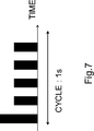
- the traffic feature may include a period (s) and / or a packet sequence for each period.
- the source device 20 may be a temperature sensor that transmits temperature information, in which case the period may be 60 seconds (ie, 60s), as shown in FIG.
- the packet sequence for each cycle may be as shown in FIG.
- the source device 20 may be a network camera that transmits moving image information, in which case the period is 1 second, as shown in FIG. (That is, 1s) may be used, and the packet sequence for each cycle may be as shown in FIG.
- the terminal type is the terminal type of the source device 20
- the QoS index is an index of service quality (QoS) required by the source device 20.
- the QoS index is a qualitative category such as delay sensitive (characteristics that are greatly affected by delay, in other words, real time) or delay robust (characteristics that are less affected by delay, in other words, non-real time).
- the QoS index may be in the range of quantitative values such as a delay time of 100 milliseconds (that is, 100 ms) or less, or a throughput of 1 Mbps or more.
- the conversion device 100 acquires, for example, the terminal type, the QoS index, and the traffic characteristics.
- the source device 20 may be a temperature sensor.
- the terminal type may be the model number of the temperature sensor
- the QoS index may be delayed robust
- the traffic features may be acquired from the temperature sensor.
- the source device 20 may be a network camera.
- the terminal type may be the model number of the network camera
- the QoS index may be delay-sensitive and / or band-sensitive
- the traffic features are acquired from the network camera. May be good.
- the conversion device 100 acquires a set of the terminal type, the QoS index, and the traffic features for the devices 20 of a plurality of transmission sources. As a result, the set for each of the plurality of source devices 20 is prepared in advance.
- the conversion device 100 determines a conversion policy indicating what kind of traffic characteristics the communication flow has by the conversion process for the original communication flow from the source device 20. decide.
- FIG. 8 is a flowchart for explaining an example of a schematic flow of the conversion policy determination process according to the first embodiment.
- the conversion device 100 first selects the traffic feature to which the divided communication flow (that is, the plurality of communication flows) matches (S310).
- the conversion policy includes the number of communication flows after division, the address information of the communication flow after division, and the transmission timing of the communication flow after division.
- the number of communication flows is determined (S320)
- the address information of the divided communication flows is determined (S330)
- the transmission timing of the divided communication flows is determined (S340).
- the conversion device 100 determines the traffic features to which the divided communication flows (that is, the plurality of communication flows) match (S310).
- the above traffic features include, for example, a packet size (bit) and / or a packet arrival interval (s).
- the packet size and / or the packet arrival interval is, for example, the distribution or statistic of the packet size and / or the packet arrival interval (eg, maximum, minimum, mean, median, variance, standard deviation, kurtosis, And / or skewness, etc.).
- the above traffic feature may include a cycle (s) and / or a packet sequence for each cycle.
- the conversion device 100 has a traffic feature to which the communication flow after division matches based on the information acquired in advance (that is, terminal type, QoS index and / or traffic feature). Select.
- the conversion device 100 first obtains a QoS index for the source device 20 acquired in advance (hereinafter, "first QoS index").
- a QoS index (hereinafter, referred to as “second QoS index”) for the communication flow after division is set based on (referred to as).
- the first QoS index can also be said to be a QoS index of the original communication flow from the source device 20.
- the second QoS index (ie, the QoS index for the divided communication flow) is different from the first QoS index (ie, the QoS index for the original communication flow from the source device 20).
- the first QoS index corresponds to a service quality that requires real-time performance
- the second QoS index corresponds to a service quality that does not require real-time performance.
- the first QoS index may be delayed sensitive, and the second QoS index may be set to delayed robust.
- the first QoS index may have a delay time of 100 ms or less, and the second QoS index may be set to a delay time of 1 s or more.
- one service can be pretended to be another service.
- a service that requires real-time performance can be pretended to be a non-real-time service.
- the conversion device 100 determines whether the conversion device 100 (determination unit 140) has a communication flow after division based on the second QoS index (that is, a QoS index for the communication flow after division). Select a matching traffic feature.
- the conversion device 100 randomly selects one of the terminal types associated with the same QoS index as the second QoS index (that is, the QoS index for the communication flow after division).
- the traffic feature associated with the one terminal type may be selected as the above-mentioned traffic feature to which the communication flow after division matches.
- the source device 20 is a network camera
- the first QoS index may be delayed sensitive and the second QoS index may be set to delayed robust.
- the model number (terminal type) of the temperature sensor associated with the delay robustness may be selected, or the traffic feature associated with the model number (terminal type) of the temperature sensor may be selected.
- the conversion device 100 may select the traffic feature closest to the second QoS index (for example, a delay time of 1 s or more).
- the conversion device 100 calculates the average value of the traffic features associated with the same QoS index as the second QoS index, and divides the average value into the communication flow after division. May be selected as the above-mentioned traffic feature to which.
- the divided communication flow may include one or more communication flows that match each of the two or more traffic features.
- the divided communication flows include one or more communication flows that match the first traffic features (eg, the traffic features of the first temperature sensor) and a second. It may include one or more communication flows that match the traffic characteristics (eg, the traffic characteristics of the second temperature sensor).
- the conversion device 100 determines the number of communication flows after division based on the selected traffic characteristics (S320).
- the conversion device 100 determines the number of communication flows that can realize the above-selected traffic features. In other words, the conversion device 100 (determination unit 140) determines the number of divided communication flows (those that match the selected traffic features) required to restore the original communication flow.
- the number of communication flows (M) after division is [the number of packets in the cycle of the original communication flow] (x) [the number of packets in the cycle required to realize the selected traffic feature].
- the number of communication flows (M) after division can be said to be the smallest integer that satisfies the following formula.
- each of the above two or more traffic features is indicated by an index i
- the number of packets in the cycle required to realize the traffic feature i is indicated by Ni
- the number of communication flows matching the traffic feature i is indicated.
- Mi is the smallest integer satisfying the following equation.
- the conversion device 100 determines the address information of the communication flow after division (S330).
- the address information includes each IP address and port number of the divided communication flow.
- a communication flow means a series of packets (a series of data) including the same IP address and the same port number. That is, the communication flow is identified by the IP address and the port number.
- the port number is a TCP (Transmission Control Protocol) or UDP (User Datagram Protocol) port number.
- the plurality of communication flows (that is, the communication flow after division) are transmitted to the restoration device 200. Therefore, the destination IP address of each of the plurality of communication flows becomes the IP address of the restoration device 200.
- each of the plurality of communication flows (that is, the communication flow after division) is a communication flow different from any other communication flow included in the plurality of communication flows. Therefore, the source IP address, the source port number, and / or the destination port number of each of the plurality of communication flows are values unique to the communication flow.
- the source port number of the communication flow after division is 20001 to 20100.
- the source port number of the communication flow after the division is also a port number unique to the communication flow.
- the source IP address may also be an IP address unique to the communication flow.
- the port number unique to the communication flow or the IP address unique to the communication flow may be a randomly selected value instead of a continuous value.
- the conversion device 100 determines the transmission timing for each of the plurality of communication flows after division (S340).
- the conversion device 100 (determining unit 140) performs the divided communication so that the transmission timing of each of the plurality of communication flows after the division matches the selected traffic characteristics. Determine the transmission timing of each flow.
- FIG. 9 shows an example of a method of determining the transmission timing of each communication flow after division according to the first embodiment.
- the original communication flow (ORIGINAL FLOW) is divided into four communication flows (FLOW 1 to 4).
- the packets may be temporarily stored in the buffer because the packets do not always arrive at the same interval for each cycle due to fluctuations in communication quality or the like.
- the packet for the communication flow 1 arrives in the original communication flow
- the packet is transmitted as a packet belonging to the communication flow 1.
- the packet for the communication flow 2 arrives in the original communication flow
- the packet is transmitted as a packet belonging to the communication flow 2.
- the communication flow 3 and the communication flow 4 are also transmitted in the same manner.
- the transmission timing of the communication flow 1 is the start time of the cycle
- the transmission timing of the communication flow 2 is the time after time 41 from the start time of the cycle
- the transmission timing of the communication flow 3 is the start of the cycle.
- the time point is 43 hours later than the time point
- the transmission timing of the communication flow 4 is a time point 45 hours later than the start time point of the cycle.
- the transmission timing of the divided communication flow determined by the conversion device 100 may be specific timings (time 41, time 43, and time 45) as shown in FIG.
- FIG. 10 is a sequence diagram for explaining an example of a schematic flow of a process of conversion and restoration of a communication flow according to the first embodiment.
- the source device 20 transmits a packet belonging to the original communication flow (that is, a packet of data generated by an application running in the source device 20) (S410).
- the conversion device 100 receives the packet belonging to the original communication flow.
- the conversion device 100 (conversion unit 120) divides the original communication flow from the source device 20 into a plurality of communication flows that match the selected traffic characteristics (S420).
- the conversion device 100 selects a traffic feature and determines a conversion policy based on the traffic feature.
- the conversion device 100 (conversion unit 120) divides the original communication flow into a plurality of communication flows according to the conversion policy.
- the conversion policy includes the number of communication flows after division, and the conversion device 100 (conversion unit 120) divides the original communication flow into the number of communication flows.
- the conversion policy includes address information (IP address and port number) of the communication flow after division, and the conversion device 100 (conversion unit 120) applies to each of the plurality of communication flows according to the address information.
- IP address and port number IP address and port number
- the conversion device 100 (conversion unit 120) has a communication flow-specific source IP address, a communication flow-specific source port number, and / or a communication flow-specific destination port number in each of the plurality of communication flows. To set.
- the conversion device 100 (conversion unit 120) sets the destination IP address to the IP address of the restoration device 200 in each of the plurality of communication flows.
- the original communication flow is divided into the plurality of communication flows according to the conversion policy determined based on the traffic characteristics. Therefore, the characteristics of the communication traffic related to the plurality of communication flows are the traffic characteristics. Fits to.
- the conversion device 100 transmits packets belonging to each of the plurality of communication flows to the restoration device 200 (S430).
- the conversion device 100 transmits a packet belonging to each of the plurality of communication flows to the restoration device 200 at a timing matching the selected traffic feature.
- the conversion policy includes transmission timing of individual packets belonging to each of the divided communication flows, and the conversion device 100 (transmission unit 130) belongs to each of the plurality of communication flows according to the transmission timing.
- the packet is transmitted to the restoration device 200.
- the restoration device 200 receives packets belonging to each of the plurality of communication flows.
- the restoration device 200 restores the plurality of communication flows to the original communication flow (S440).
- the conversion device 100 transmits the above conversion policy to the restoration device 200.
- the restoration device 200 restores the plurality of communication flows to the original communication flow according to the conversion policy.
- the above conversion policy includes the address information (IP address and port number) of the divided communication flow and the address information (IP address and port number) of the original communication flow.
- the restoration device 200 (restoration unit 220) replaces the address information of the divided communication flow (that is, the plurality of communication flows) with the address information of the original communication flow.
- the restoration device 200 transmits a packet belonging to the original communication flow (that is, the restored traffic) to the destination device 30 (S450).
- the destination device 30 receives the packet belonging to the original communication flow.
- the original communication flow is divided and restored. This makes it possible, for example, to mislead the estimation of the source by analyzing the communication traffic.
- the estimation of the source based on the communication traffic is performed by analyzing the statistics of the characteristics of the communication traffic such as the packet transmission interval and the packet size. Therefore, for example, as shown in FIG. 11, when the source device 20 (for example, a network camera) transmits a statistic (for example, a moving image traffic) that requires real-time performance to the destination device 30, the network 10 The statistics of the characteristics of the traffic are analyzed, and it can be estimated that the traffic requiring real-time performance is transmitted from the source device 20.
- the traffic that requires real-time performance for example, moving image traffic
- the traffic that does not require real-time performance for example, sensor traffic.
- Divided into traffic therefore, in the network 10, the statistics of the characteristics of the traffic after division are analyzed, and it can be erroneously estimated that the traffic that does not require real-time performance is transmitted.
- the original traffic eg, the traffic that requires real-time performance
- another traffic eg, the traffic that requires real-time performance
- it can be disguised as another packet that does not require real-time performance. That is, by dividing the communication flow and reducing the traffic amount in each flow, it is possible to make the high-frequency communication look like the low-frequency communication. Therefore, it is possible to induce a mispresumption about the source by the communication traffic analysis.
- the original communication flow is divided into a plurality of communication flows. For example, if the number of packets in the cycle of the original communication flow is an integral multiple of the number of communication flows, the packets in the original communication flow can be allocated to a plurality of flows without excess or deficiency.
- the number of packets in the cycle of the original communication flow is not often an integral multiple of the number of flows.
- the divided communication flow may include a communication flow with a small number of packets, and the communication flow may not be well adapted to the selected traffic features (particularly, packet arrival intervals). As a result, it can be difficult to accurately induce mispresumption.
- the conversion device 100 (conversion unit 120) has the packet feature of the communication flow included in the plurality of communication flows (that is, the communication flow after division). Dummy packets are added to the communication flow to match the packet arrival intervals contained in the selected traffic features.
- the number of packets per unit time in the communication flow included in the plurality of communication flows is included in the packet arrival interval (that is, the packet arrival interval) included in the selected traffic feature.
- the conversion device 100 converts dummy packets to the communication flow. That is, the dummy packet is added to the communication flow in which the number of packets per unit time is smaller than the number of packets corresponding to the packet arrival interval included in the selected traffic feature among the plurality of communication flows.
- the dummy packet has the same address information as the packet included in the communication flow.
- the communication flows included in the plurality of communication flows are selected as the traffic features (particularly, packet arrival intervals). Will be compatible with. Therefore, misestimation by analysis of communication traffic can be accurately induced.
- the restoration device 200 uses the dummy packet when restoring the plurality of communication flows (that is, the communication flow after division) to the original communication flow. Discard.
- the conversion device 100 converts identification information to the header or payload (for example, the last few bits) of the dummy packet.
- the restoration device 200 identifies the packet containing the identification information as a dummy packet, and discards the packet (that is, the dummy packet).
- Second variant> When large-sized data is transmitted by the source device 20, the data is fragmented into an MTU (Maximum Transmission Unit), which is the maximum size of packets that can be processed by the network. In this case, the distribution of the size of the packet transmitted by the source device 20 is biased toward the MTU.
- MTU Maximum Transmission Unit
- the distribution of the size of the packet transmitted by the source device 20 is not biased toward the MTU.
- an environmental sensor such as a temperature sensor transmits data having a size smaller than that of the MTU (for example, several bytes to several hundred bytes).
- the conversion device 100 has the packet feature of the communication flow included in the plurality of communication flows (that is, the communication flow after division). Performs specific processing (eg, packet division, addition of dummy bits, or packet aggregation) on packets belonging to the original communication flow so as to match the packet size included in the selected traffic features. ..
- the restoration device 200 restores the plurality of communication flows (that is, the communication flow after division) to the original communication flow. Restoration processing corresponding to the processing is also performed.
- the conversion device 100 converts identification information to the header or payload (for example, the last few bits) of the packet generated by the specific process.
- the restoration device 200 identifies a packet containing the identification information as a packet generated by the specific processing, and performs the restoration processing on the packet.
- the identification information may be identification information according to the content of the specific process, and the restoration device 200 (restoration unit 220) may identify the content of the specific process based on the identification information. Good.
- the conversion device 100 (conversion unit 120) has a traffic characteristic of a communication flow included in the plurality of communication flows (that is, a communication flow after division).
- the packet belonging to the original communication flow may be divided into a plurality of packets so as to match the packet size included in the selected traffic feature.
- the conversion device 100 may divide the packet belonging to the original communication flow into a plurality of packets.
- the conversion device 100 converts a packet exceeding the maximum value of the packet size distribution included in the selected traffic feature into packets having a packet size with a high probability of occurrence in the distribution.
- the conversion device 100 converts a packet exceeding the maximum value of the packet size distribution included in the selected traffic feature into packets having a packet size with a high probability of occurrence in the distribution.
- Good For example, when the packet belonging to the original communication flow is a 1500-byte packet, the average packet size is 500 bytes, and the maximum value of the packet size is 1000 bytes in the selected traffic feature, the original.
- the packet of the communication flow of the above may be divided into a packet of 500 bytes and a packet of 1000 bytes. Alternatively, the packet of the original communication flow may be divided into two packets of 750 bytes.
- the conversion device 100 may divide a packet exceeding the maximum value of the packet size distribution included in the selected traffic feature into a stochastically selected packet. For example, when 10 packets of the original communication flow arrive and the size of each of the 10 packets is 800 bytes, 4 packets are selected from the 10 packets and the packet is selected. Each of the four packets may be divided into a 500-byte packet and a 300-byte packet. This makes it possible, for example, to bring the traffic characteristics of the divided communication flow closer to a more natural probability distribution.
- the packet may be divided as described above.
- the size of the packet becomes smaller, and the packet belonging to the divided communication flow matches the packet size included in the selected traffic feature. Therefore, misestimation by analysis of communication traffic can be accurately induced.
- the conversion device 100 For the restoration process in the restoration device 200, the conversion device 100 (conversion unit 120) identifies each header or payload (for example, the last few bits) of the plurality of packets (that is, the divided packets). Information may be given. The identification information may indicate the original packet and the order in the original packet.
- the conversion device 100 (conversion unit 120) has a packet feature of the communication flow included in the plurality of communication flows (that is, the communication flow after division). However, a dummy bit may be added to the packet belonging to the original communication flow so as to match the packet size included in the selected traffic feature.
- the conversion device 100 may add a dummy bit to the packet belonging to the original communication flow.
- the conversion device 100 (conversion unit 120) of the original communication flow so that the size of the packet belonging to the original communication flow becomes the average value of the packet sizes included in the selected traffic feature. Dummy bits may be added to the above packet.
- dummy bits may be added as described above.
- the size of the packet becomes larger, and the packet belonging to the divided communication flow becomes suitable for the packet size included in the selected traffic feature. Therefore, misestimation by analysis of communication traffic can be accurately induced.
- the conversion device 100 may add identification information to the header or payload (for example, the last few bits) of each packet to which the dummy bits are added. Good.
- the identification information may indicate the number of added bits and the position of the added bits (for example, the end of a packet).
- the conversion device 100 has a traffic characteristic of the communication flow included in the plurality of communication flows (that is, the communication flow after division). , Packets belonging to the original communication flow and one or more other packets may be aggregated to fit the packet size included in the selected traffic features. That is, the conversion device 100 (conversion unit 120) may generate an aggregated packet including the packet of the original communication flow and the one or more other packets.
- the one or more other packets may be packets belonging to another original communication flow different from the original communication flow. That is, packets from a plurality of original communication flows may be aggregated. Further, the other original communication flow may be the communication flow of the device 20 of the other transmission source. That is, packets from the devices 20 of a plurality of sources may be aggregated.
- the conversion device 100 may aggregate the packet of the original communication flow and one or more other packets.
- the conversion device 100 sets the packet of the original communication flow and the packet of the original communication flow so that the size of the aggregated packet becomes the average value of the packet sizes included in the selected traffic features. It may be aggregated with one or more other packets.
- packets may be aggregated as described above.
- the size of the packet becomes larger, and the packet belonging to the divided communication flow becomes suitable for the packet size included in the selected traffic feature. Therefore, misestimation by analysis of communication traffic can be accurately induced.
- the communication flow after division includes, for example, communication flows from a plurality of devices, it may be more difficult to estimate the device 20 of each transmission source.
- the conversion device 100 may add identification information to the header or payload (for example, the last few bits) of the aggregated packet for the restoration process in the restoration device 200.
- the identification information may indicate a delimiter between a plurality of packets in the aggregated packet.
- the conversion device 100 (conversion unit 120) divides the original communication flow from the transmission device 20 into a plurality of communication flows. This makes it possible to make the original traffic (for example, a traffic that requires real-time performance) look like another traffic (for example, another traffic that does not require real-time performance).
- the first embodiment is not limited to this example.
- the conversion device 100 (conversion unit 120) aggregates a plurality of original communication flows from the source device 20.
- the conversion device 100 (conversion unit 120) may aggregate a plurality of original communication flows from a single source device 20 or a plurality of original communication flows from a plurality of source devices 20. You may. Further, the conversion device 100 (transmission unit 130) transmits the aggregated communication flow to the restoration device 200.
- the conversion device 100 is a device different from the source device 20, and the restoration device 200 is a device different from the destination device 30.
- the first embodiment is not limited to this example.
- the conversion device 100 may be the source device 20. That is, the operation or function of the conversion device 100 may be implemented in the source device 20.
- the restoration device 200 may be the destination device 30. That is, the operation or function of the restoration device 200 may be implemented in the destination device 30.
- Second embodiment A second embodiment of the present disclosure will be described with reference to FIGS. 13-18.
- the first embodiment described above is a specific embodiment, but the second embodiment is a more generalized embodiment.
- FIG. 13 shows an example of a schematic configuration of the system 2 according to the second embodiment.
- the system 2 includes a network 50, a converter 600 and a restorer 700.
- the description of the network 50, the conversion device 600, and the restoration device 700 is the same as the description of the network 10, the conversion device 100, and the restoration device 200 according to the first embodiment, except for the difference in reference numerals. Therefore, a duplicate description will be omitted here.
- the network 50, the conversion device 600, and the restoration device 700 according to the second embodiment are not limited to this example.
- FIG. 14 is a block diagram showing an example of a schematic functional configuration of the conversion device 600 according to the second embodiment.
- the conversion device 600 includes a conversion unit 610 and a transmission unit 620.
- the description of the conversion unit 610 and the transmission unit 620 is the same as the description of the conversion unit 120 and the transmission unit 130 according to the first embodiment, except for the difference in reference numerals. Therefore, a duplicate description will be omitted here.
- the conversion unit 610 and the transmission unit 620 according to the second embodiment are not limited to this example.
- FIG. 15 is a block diagram showing an example of a schematic hardware configuration of the conversion device 600 according to the second embodiment.
- the conversion device 600 includes a processor 681, a main memory 683, a storage 685, a communication interface 687, and an input / output interface 689.
- the processor 681, the main memory 683, the storage 685, the communication interface 687, and the input / output interface 689 are connected to each other via the bus 691.
- the description of the hardware configuration of the conversion device 600 is the same as the description of the hardware configuration of the conversion device 100 according to the first embodiment, except for the difference in reference numerals. Therefore, a duplicate description will be omitted here.
- the hardware configuration of the conversion device 600 according to the second embodiment is not limited to this example.
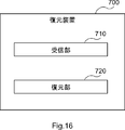
- FIG. 16 is a block diagram showing an example of a schematic functional configuration of the restoration device 700 according to the second embodiment.
- the restoration device 700 includes a reception unit 710 and a restoration unit 720.
- the description of the receiving unit 710 and the restoring unit 720 is the same as the description of the receiving unit 210 and the restoring unit 220 according to the first embodiment, except for the difference in reference numerals. Therefore, a duplicate description will be omitted here.
- the receiving unit 710 and the restoring unit 720 according to the second embodiment are not limited to this example.
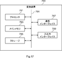
- FIG. 17 is a block diagram showing an example of a schematic hardware configuration of the restoration device 700 according to the second embodiment.
- the restoration device 700 includes a processor 781, a main memory 783, a storage 785, a communication interface 787, and an input / output interface 789.
- the processor 781, the main memory 783, the storage 785, the communication interface 787, and the input / output interface 789 are connected to each other via the bus 791.
- the description of the hardware configuration of the restoration device 700 is the same as the description of the hardware configuration of the restoration device 200 according to the first embodiment, except for the difference in reference numerals. Therefore, a duplicate description will be omitted here.
- the hardware configuration of the restoration device 700 according to the second embodiment is not limited to this example.
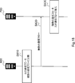
- FIG. 18 is a sequence diagram for explaining an example of a schematic flow of the processing of conversion and restoration of the communication flow according to the second embodiment.
- the conversion device 600 (conversion unit 610) divides the original communication flow from the source device into a plurality of communication flows that match the selected traffic characteristics (S810).
- the conversion device 100 transmits packets belonging to each of the plurality of communication flows to the restoration device 200 (S820).
- the restoration device 200 receives the packet belonging to each of the plurality of flows.
- the restoration device 200 restores the plurality of communication flows to the original communication flow (S830).
- the original communication flow is converted (that is, divided) and restored. This makes it possible, for example, to mislead the estimation of the source by analyzing the communication traffic.
- the steps in the processing described herein do not necessarily have to be performed in chronological order in the order described in the flowchart or sequence diagram.
- the steps in the process may be executed in an order different from the order described as a flowchart or a sequence diagram, or may be executed in parallel.
- some of the steps in the process may be deleted, and additional steps may be added to the process.
- a method including processing of a component of the conversion device or the restoration device described in the present specification may be provided, and a program for causing the processor to execute the processing of the component may be provided.
- a non-transitory computer readable recording medium may be provided that can be read by the computer on which the program is recorded.
- Appendix 2 The method according to Appendix 1, wherein the selected traffic feature is a traffic feature selected based on a second quality of service index that is different from the first quality of service index for the original communication flow.
- the first service quality index corresponds to the service quality that requires real-time performance.
- the second service quality index corresponds to service quality that does not require real-time performance. The method described in Appendix 2.
- Addendum 1 further includes setting a source IP (Internet Protocol) address unique to the communication flow, a source port number unique to the communication flow, or a destination port number unique to the communication flow in each of the plurality of communication flows. The method according to any one of 4 to 4.
- IP Internet Protocol
- the selected traffic features include packet arrival intervals. Adding a dummy packet to the communication flow so that the traffic characteristics of the communication flow included in the plurality of communication flows match the packet arrival interval.
- the selected traffic features include packet size and The packet belonging to the original communication flow is divided into a plurality of packets, or the packet belongs to the original communication flow so that the traffic characteristics of the communication flow included in the plurality of communication flows match the packet size. Adding a dummy bit or aggregating a packet belonging to the original communication flow with one or more other packets.
- the conversion device Divide the original communication flow from the source device into multiple communication flows that match the selected traffic characteristics. A packet belonging to each of the plurality of communication flows is transmitted to the restoration device, and the packet is transmitted to the restoration device. The restoration device is Upon receiving the packet belonging to each of the plurality of communication flows, Restoring the plurality of communication flows to the original communication flow, system.
- Appendix 9 The system according to Appendix 8, wherein the selected traffic feature is a traffic feature selected based on a second quality of service index that is different from the first quality of service index for the original communication flow.
- the first service quality index corresponds to the service quality that requires real-time performance.
- the second service quality index corresponds to service quality that does not require real-time performance.
- the conversion device sets a source IP (Internet Protocol) address peculiar to the communication flow, a source port number peculiar to the communication flow, or a destination port number peculiar to the communication flow in each of the plurality of communication flows.
- the system according to any one of 1 to 11.
- the selected traffic features include packet arrival intervals.
- the conversion device adds a dummy packet to the communication flow so that the traffic characteristics of the communication flow included in the plurality of communication flows match the packet arrival interval.
- the system according to any one of Appendix 8 to 12.
- the selected traffic features include packet size and
- the conversion device divides a packet belonging to the original communication flow into a plurality of packets or performs the original communication so that the traffic characteristics of the communication flows included in the plurality of communication flows match the packet size.
- a dummy bit is added to a packet belonging to the flow, or a packet belonging to the original communication flow and one or more other packets are aggregated.
- the system according to any one of Appendix 8 to 13.
- a converter that divides the original communication flow from the source device into multiple communication flows that match the selected traffic characteristics.
- a transmission unit that transmits packets belonging to each of the plurality of communication flows to a restoration device that restores the plurality of communication flows to the original communication flow.
- Appendix 16 The converter according to Appendix 15, wherein the selected traffic feature is a traffic feature selected based on a second quality of service index that is different from the first quality of service index for the original communication flow.
- the first service quality index corresponds to the service quality that requires real-time performance.
- the second service quality index corresponds to service quality that does not require real-time performance.
- the conversion unit sets a source IP (Internet Protocol) address peculiar to the communication flow, a source port number peculiar to the communication flow, or a destination port number peculiar to the communication flow in each of the plurality of communication flows.
- the conversion device according to any one of 18 to 18.
- the selected traffic features include packet arrival intervals.
- the conversion unit adds a dummy packet to the communication flow so that the traffic characteristics of the communication flows included in the plurality of communication flows match the packet arrival interval.
- the conversion device according to any one of Supplementary note 15 to 19.
- the selected traffic features include packet size and
- the conversion unit divides a packet belonging to the original communication flow into a plurality of packets or performs the original communication so that the traffic characteristics of the communication flows included in the plurality of communication flows match the packet size.
- a dummy bit is added to a packet belonging to the flow, or a packet belonging to the original communication flow and one or more other packets are aggregated.
- the conversion device according to any one of Appendix 15 to 20.
- a receiver that receives packets belonging to each of the plurality of communication flows from a conversion device that divides the original communication flow from the source device into a plurality of communication flows that match the selected traffic characteristics.
- a restoration unit that restores the plurality of communication flows to the original communication flow, Restoration device equipped with.
Landscapes
- Engineering & Computer Science (AREA)
- Computer Networks & Wireless Communication (AREA)
- Signal Processing (AREA)
- Computer Security & Cryptography (AREA)
- Quality & Reliability (AREA)
- Computer Hardware Design (AREA)
- Computing Systems (AREA)
- General Engineering & Computer Science (AREA)
- Data Exchanges In Wide-Area Networks (AREA)
Priority Applications (3)
| Application Number | Priority Date | Filing Date | Title |
|---|---|---|---|
| US17/770,486 US20220393987A1 (en) | 2019-11-12 | 2019-11-12 | Method, system, and conversion apparatus |
| PCT/JP2019/044409 WO2021095138A1 (ja) | 2019-11-12 | 2019-11-12 | 方法、システム及び変換装置 |
| JP2021555673A JP7396368B2 (ja) | 2019-11-12 | 2019-11-12 | 方法、システム及び変換装置 |
Applications Claiming Priority (1)
| Application Number | Priority Date | Filing Date | Title |
|---|---|---|---|
| PCT/JP2019/044409 WO2021095138A1 (ja) | 2019-11-12 | 2019-11-12 | 方法、システム及び変換装置 |
Publications (1)
| Publication Number | Publication Date |
|---|---|
| WO2021095138A1 true WO2021095138A1 (ja) | 2021-05-20 |
Family
ID=75912073
Family Applications (1)
| Application Number | Title | Priority Date | Filing Date |
|---|---|---|---|
| PCT/JP2019/044409 Ceased WO2021095138A1 (ja) | 2019-11-12 | 2019-11-12 | 方法、システム及び変換装置 |
Country Status (3)
| Country | Link |
|---|---|
| US (1) | US20220393987A1 (https=) |
| JP (1) | JP7396368B2 (https=) |
| WO (1) | WO2021095138A1 (https=) |
Citations (1)
| Publication number | Priority date | Publication date | Assignee | Title |
|---|---|---|---|---|
| JP2010130329A (ja) * | 2008-11-27 | 2010-06-10 | Mitsubishi Electric Corp | 通信装置および中継装置 |
Family Cites Families (4)
| Publication number | Priority date | Publication date | Assignee | Title |
|---|---|---|---|---|
| SE0000707D0 (sv) * | 1999-05-04 | 2000-03-01 | Magnus Agervald | System för överförande av data via flera kommunikationsvägar |
| EP1065845A3 (en) * | 1999-06-30 | 2003-08-06 | Nec Corporation | Shooting blanks method for high throughput in input-queued switches |
| CA3028397A1 (en) * | 2016-06-18 | 2017-12-21 | Clevernet, Inc. | Intelligent adaptive transport layer to enhance performance using multiple channels |
| US20190029002A1 (en) * | 2017-07-18 | 2019-01-24 | GM Global Technology Operations LLC | Intelligent vehicle-based communication mangement |
-
2019
- 2019-11-12 JP JP2021555673A patent/JP7396368B2/ja active Active
- 2019-11-12 WO PCT/JP2019/044409 patent/WO2021095138A1/ja not_active Ceased
- 2019-11-12 US US17/770,486 patent/US20220393987A1/en not_active Abandoned
Patent Citations (1)
| Publication number | Priority date | Publication date | Assignee | Title |
|---|---|---|---|---|
| JP2010130329A (ja) * | 2008-11-27 | 2010-06-10 | Mitsubishi Electric Corp | 通信装置および中継装置 |
Non-Patent Citations (2)
| Title |
|---|
| 4 February 2011 (2011-02-04), GENEBANK: "GRN_EB Homo sapiens cDNA 5', mRNA sequence.", retrieved from NCBI Database accession no. CN365873.1 * |
| IMANI, M. ET AL.: "Mockingbird: Defending Against Deep-Learning-Based Website Fingerprinting Attacks with Adversarial Traces", ARXIV:1902.06626V2, 16 May 2019 (2019-05-16), pages 1 - 14, Retrieved from the Internet <URL:https://arxiv.org/pdf/1902.06626v2.pdf> [retrieved on 20191204] * |
Also Published As
| Publication number | Publication date |
|---|---|
| JPWO2021095138A1 (https=) | 2021-05-20 |
| US20220393987A1 (en) | 2022-12-08 |
| JP7396368B2 (ja) | 2023-12-12 |
Similar Documents
| Publication | Publication Date | Title |
|---|---|---|
| US11700275B2 (en) | Detection of malware and malicious applications | |
| Strayer et al. | Botnet detection based on network behavior | |
| CN106416171B (zh) | 一种特征信息分析方法及装置 | |
| JP4658098B2 (ja) | フロー情報制限装置および方法 | |
| KR101295708B1 (ko) | 트래픽 수집장치, 트래픽 분석장치, 시스템 및 그 분석방법 | |
| WO2009112044A1 (en) | Technique for classifying network traffic and for validating a mechanism for calassifying network traffic | |
| WO2016110273A1 (zh) | 一种对访问请求进行限制的系统和方法 | |
| Suarez-Varela et al. | Flow monitoring in Software-Defined Networks: Finding the accuracy/performance tradeoffs | |
| Seufert et al. | Marina: Realizing ML-driven real-time network traffic monitoring at terabit scale | |
| Gharakheili et al. | iTeleScope: Softwarized network middle-box for real-time video telemetry and classification | |
| WO2019159833A1 (ja) | 脅威情報抽出装置及び脅威情報抽出システム | |
| CN115567457A (zh) | Tsn网络数据传输方法及装置 | |
| CN104580228A (zh) | 对来自网络的访问请求产生黑名单的系统和方法 | |
| JP7396368B2 (ja) | 方法、システム及び変換装置 | |
| Cardozo et al. | Bufferbloat systematic analysis | |
| CN107689967A (zh) | 一种DDoS攻击检测方法和装置 | |
| JP6662812B2 (ja) | 計算装置及び計算方法 | |
| US20180331930A1 (en) | Non-transitory computer-readable recording medium recording burst detection program, burst detection method and information processing apparatus | |
| CN104579841B (zh) | 根据接收的udp报文产生对特定统计数据项的统计结果的系统 | |
| JP4766703B2 (ja) | エッジノードおよび帯域制御方法 | |
| Lübben et al. | Estimation method for the delay performance of closed-loop flow control with application to TCP | |
| Salem et al. | Persistent dataset generation using real-time operative framework | |
| EP3580892B1 (en) | Transport layer monitoring and performance assessment for ott services | |
| Bakhshi | Evaluating Modern TCP Congestion Control Algorithms | |
| Lee | An In-depth Latency Measurement Tool for Large-scale System |
Legal Events
| Date | Code | Title | Description |
|---|---|---|---|
| 121 | Ep: the epo has been informed by wipo that ep was designated in this application |
Ref document number: 19952521 Country of ref document: EP Kind code of ref document: A1 |
|
| ENP | Entry into the national phase |
Ref document number: 2021555673 Country of ref document: JP Kind code of ref document: A |
|
| NENP | Non-entry into the national phase |
Ref country code: DE |
|
| 122 | Ep: pct application non-entry in european phase |
Ref document number: 19952521 Country of ref document: EP Kind code of ref document: A1 |