WO2021095097A1 - Molding device and molding method - Google Patents
Molding device and molding method Download PDFInfo
- Publication number
- WO2021095097A1 WO2021095097A1 PCT/JP2019/044150 JP2019044150W WO2021095097A1 WO 2021095097 A1 WO2021095097 A1 WO 2021095097A1 JP 2019044150 W JP2019044150 W JP 2019044150W WO 2021095097 A1 WO2021095097 A1 WO 2021095097A1
- Authority
- WO
- WIPO (PCT)
- Prior art keywords
- roller
- mandrel
- molded
- grip portion
- along
- Prior art date
Links
Images


Classifications
-
- B—PERFORMING OPERATIONS; TRANSPORTING
- B29—WORKING OF PLASTICS; WORKING OF SUBSTANCES IN A PLASTIC STATE IN GENERAL
- B29C—SHAPING OR JOINING OF PLASTICS; SHAPING OF MATERIAL IN A PLASTIC STATE, NOT OTHERWISE PROVIDED FOR; AFTER-TREATMENT OF THE SHAPED PRODUCTS, e.g. REPAIRING
- B29C53/00—Shaping by bending, folding, twisting, straightening or flattening; Apparatus therefor
- B29C53/36—Bending and joining, e.g. for making hollow articles
- B29C53/38—Bending and joining, e.g. for making hollow articles by bending sheets or strips at right angles to the longitudinal axis of the article being formed and joining the edges
- B29C53/40—Bending and joining, e.g. for making hollow articles by bending sheets or strips at right angles to the longitudinal axis of the article being formed and joining the edges for articles of definite length, i.e. discrete articles
- B29C53/42—Bending and joining, e.g. for making hollow articles by bending sheets or strips at right angles to the longitudinal axis of the article being formed and joining the edges for articles of definite length, i.e. discrete articles using internal forming surfaces, e.g. mandrels
-
- B—PERFORMING OPERATIONS; TRANSPORTING
- B29—WORKING OF PLASTICS; WORKING OF SUBSTANCES IN A PLASTIC STATE IN GENERAL
- B29C—SHAPING OR JOINING OF PLASTICS; SHAPING OF MATERIAL IN A PLASTIC STATE, NOT OTHERWISE PROVIDED FOR; AFTER-TREATMENT OF THE SHAPED PRODUCTS, e.g. REPAIRING
- B29C53/00—Shaping by bending, folding, twisting, straightening or flattening; Apparatus therefor
- B29C53/02—Bending or folding
- B29C53/04—Bending or folding of plates or sheets
- B29C53/043—Bending or folding of plates or sheets using rolls or endless belts
-
- B—PERFORMING OPERATIONS; TRANSPORTING
- B29—WORKING OF PLASTICS; WORKING OF SUBSTANCES IN A PLASTIC STATE IN GENERAL
- B29C—SHAPING OR JOINING OF PLASTICS; SHAPING OF MATERIAL IN A PLASTIC STATE, NOT OTHERWISE PROVIDED FOR; AFTER-TREATMENT OF THE SHAPED PRODUCTS, e.g. REPAIRING
- B29C53/00—Shaping by bending, folding, twisting, straightening or flattening; Apparatus therefor
- B29C53/80—Component parts, details or accessories; Auxiliary operations
- B29C53/82—Cores or mandrels
-
- Y—GENERAL TAGGING OF NEW TECHNOLOGICAL DEVELOPMENTS; GENERAL TAGGING OF CROSS-SECTIONAL TECHNOLOGIES SPANNING OVER SEVERAL SECTIONS OF THE IPC; TECHNICAL SUBJECTS COVERED BY FORMER USPC CROSS-REFERENCE ART COLLECTIONS [XRACs] AND DIGESTS
- Y02—TECHNOLOGIES OR APPLICATIONS FOR MITIGATION OR ADAPTATION AGAINST CLIMATE CHANGE
- Y02T—CLIMATE CHANGE MITIGATION TECHNOLOGIES RELATED TO TRANSPORTATION
- Y02T50/00—Aeronautics or air transport
- Y02T50/40—Weight reduction
Definitions
- the present disclosure relates to a molding apparatus and a molding method, particularly a molding apparatus and a molding method for shaping a reinforcing fiber sheet which is a material of a composite material.
- CFRP carbon fiber reinforced plastic
- CFRP carbon fiber reinforced plastic
- Patent Document 1 discloses a technique for cooling a preform of a heated carbon fiber thermoplastic resin while compacting it with a roller.
- the present disclosure has been made in view of such circumstances, and provides a molding apparatus and a molding method capable of efficiently shaping a reinforcing fiber sheet and appropriately generating an interlayer slip.
- the purpose is.
- the molding apparatus and molding method of the present disclosure employ the following means. That is, the molding apparatus according to the present disclosure has a mandrel having an arc-shaped cross section and a circular cross-section, which can be moved along the surface of the mandrel, and is used on a material to be molded placed on the mandrel.
- a roller that applies a pressing force to the mandrel, a grip portion that grips the material to be molded on the outside of the roller to the mandrel and applies a tensile force to the material to be molded, and the mandrel with the roller.
- the roller drive unit that moves along the surface of the roller, the grip unit drive unit that moves the grip portion, and the position of the roller and the position of the grip portion are synchronized, and the roller and the grip portion are located between the roller and the grip portion.
- a control unit that controls the roller drive unit and the grip unit drive unit is provided so that the material to be molded is arranged in a direction perpendicular to the vertical direction of the mandrel.
- the molding method according to the present disclosure relates to a mandrel having an arc-shaped cross section and a material to be molded which has a circular cross-section and can move along the surface of the mandrel and is placed on the mandrel.
- a roller that applies a pressing force, a grip portion that grips the material to be molded on the outside of the roller to the mandrel and applies a tensile force to the material to be molded, and the roller on the surface of the mandrel.
- a molding method using a molding apparatus including a roller drive unit that moves the grip portion along the mandrel and a grip portion drive portion that moves the grip portion, wherein the roller is mounted on the mandrel with respect to a material to be molded.
- the step is to synchronize the position of the roller with the position of the grip portion to arrange the material to be molded between the roller and the grip portion in a direction perpendicular to the vertical direction of the mandrel.
- the reinforcing fiber sheet can be efficiently shaped, and inter-slip can be appropriately generated.
- FIG. 9A It is a partially enlarged view of FIG. It is a partially enlarged view of FIG. It is a cross-sectional view which shows the reinforcing fiber sheet before shaping (FIG. 9A) and after shaping (FIG. 9B) by the conventional molding method.
- the molding apparatus 1 is used when molding a composite material, for example, carbon fiber reinforced plastic (CFRP), and is particularly applied to a step of bending (forming) a plurality of laminated reinforcing fiber sheets.
- CFRP carbon fiber reinforced plastic
- the reinforcing fiber sheet is an example of the material to be molded according to the present disclosure.
- Reinforcing fiber sheets are, for example, prepregs, dry fibers and the like.
- the molding apparatus 1 according to the present disclosure can be used in both cases of forming a carbon fiber reinforced plastic (CFRP) molded product using a thermosetting resin and a CFRP molded product using a thermoplastic resin. Applicable.
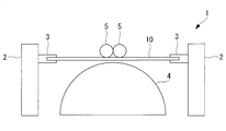
- the molding apparatus 1 includes a grip portion driving unit 2, a grip portion 3, a mandrel 4, a roller 5, and the like. Further, as shown in FIG. 5, the molding apparatus 1 further includes a control unit 6 and a roller drive unit 7.
- the mandrel 4 has an arcuate cross section, and a reinforcing fiber sheet 10 such as a prepreg is placed on the arcuate surface.
- the reinforcing fiber sheet 10 is an example of a material to be molded.
- the reinforcing fiber sheet 10 is pressed by the roller 5 on the mandrel 4 to form a shape along the arc surface of the mandrel 4.
- the roller 5 has a circular cross section and can move while rolling along the surface of the mandrel 4.
- the roller 5 applies a pressing force to the reinforcing fiber sheet 10 placed on the mandrel 4.
- a total of two rollers 5 are installed on each side of the vertical straight line (center line) passing through the center of the circle of the mandrel 4.
- the grip portion 3 grips the reinforcing fiber sheet 10 on the outer side of the roller 5 with respect to the mandrel 4. Further, the grip portion 3 applies a tensile force to the reinforcing fiber sheet 10.
- a total of two grips 3 are installed, one on each side, about the vertical line (center line) of the mandrel 4.
- two or more rollers 5 and the grip portion 3 may be installed as long as the position of the roller 5 and the position of the grip portion 3 can be synchronized.
- the grip portion 3 applies a tensile force to the reinforcing fiber sheet 10 between the roller 5 and the grip portion 3 before being shaped along the mandrel 4.
- the material to be molded is surely arranged along the roller 5, so that the difference in the peripheral length of the reinforcing fiber sheet 10 in contact with the roller 5 is zero regardless of the difference in the position of the roller 5 due to the movement of the roller 5. become.
- the roller drive unit 7 has a configuration in which the roller 5 is moved along the surface of the mandrel 4.
- the roller drive unit 7 adjusts the position of the roller 5 based on the drive signal received from the control unit 6.
- the grip portion drive unit 2 moves the grip portion 3 in a direction parallel to the vertical line of the mandrel 4, that is, in the vertical direction.
- the grip unit drive unit 2 adjusts the position of the grip unit 3 based on the drive signal received from the control unit 6.
- One grip portion driving unit 2 is provided for each grip portion 3.
- the control unit 6 synchronizes the position of the roller 5 with the position of the grip portion 3, so that the reinforcing fiber sheet 10 between the roller 5 and the grip portion 3 is perpendicular to the vertical direction of the mandrel 4, that is, horizontal.
- the roller drive unit 7 and the grip unit drive unit 2 are controlled so as to be arranged in the direction.
- the control unit 6 generates a drive signal related to the movement of the roller drive unit 7 and transmits the drive signal to the roller drive unit 7. Further, the control unit 6 generates a drive signal related to the movement of the grip unit drive unit 2 and transmits a drive signal related to the movement of the grip unit drive unit 2.
- the reinforcing fiber sheet 10 is gripped by the grip portion 3 so as to be arranged in the horizontal direction. Then, the grip portion driving unit 2 moves the grip portion 3 downward, and the reinforcing fiber sheet 10 is arranged on the mandrel 4. At this time, the grip portion 3 applies a tensile force to the reinforcing fiber sheet 10.
- the roller drive unit 7 moves the roller 5 from the center of the mandrel 4 to the outside along the surface of the mandrel 4.
- the roller 5 applies a pressing force to the reinforcing fiber sheet 10.
- the reinforcing fiber sheet 10 is gradually bent downward from the uppermost end of the mandrel 4 to form a shape that follows the shape of the mandrel 4.
- the shaping may be performed using only one roller 5 instead of two.
- the reinforcing fiber sheet 10 may be cooled while bending the reinforcing fiber sheet 10 by pressing with the roller 5.
- the gripping portion 3 releases the gripping of the reinforcing fiber sheet 10 as shown in FIG. Then, the roller 5 deforms the end portion of the reinforcing fiber sheet 10 along the mandrel 4.
- the position of the roller 5 and the position of the grip portion 3 are synchronized so that the reinforcing fiber sheet 10 between the roller 5 and the grip portion 3 is always adjusted to be in the horizontal direction.
- the region where the interlayer slip occurs becomes local. 7 and 8 are partially enlarged views of FIG. Since the position of the roller 5 and the position of the grip portion 3 are adjusted, the reinforcing fiber sheet 10 between the roller 5 and the grip portion 3 is arranged in the direction perpendicular to the vertical direction of the mandrel 4, that is, in the horizontal direction. , The difference in the circumference of the reinforcing fiber sheet 10 shaped along the mandrel 4 from the start of shaping to a certain time T1, and the circumference of the reinforcing fiber sheet 10 arranged along the roller 5 at a certain time T1. The difference is equal.
- the difference in the peripheral length of the reinforcing fiber sheet 10 in the mandrel 4 is the length of the mandrel 4 side (inner surface side) of the reinforcing fiber sheet 10 in contact with the mandrel 4 from the start of shaping to a certain time T1.
- This is the difference between the length (the alternate long and short dash line portion of the region A in FIG. 7) and the length (the alternate long and short dash line portion of the region A in FIG. 7) opposite to the mandrel 4.
- the difference in the peripheral length of the reinforcing fiber sheet 10 in the mandrel 4 is caused by the diameter of the mandrel 4 and the plate thickness t of the reinforcing fiber sheet 10, and is represented by the following formula (1).
- R is the radius of the mandrel 4
- ⁇ is the angle formed by the vertical line of the mandrel 4 at time T1 and the line connecting the center of the mandrel 4 and the center of the roller 5.
- the difference in the peripheral length of the reinforcing fiber sheet 10 in the roller 5 is the length of the reinforcing fiber sheet 10 in contact with the roller 5 at a certain time T1 on the roller 5 side (inner surface side) (thick solid line in the region B in FIG. 7). This is the difference between the length (the portion) and the length (the broken line portion of the region B in FIG. 7) on the side opposite to the roller 5 (outer surface side).
- the difference in the peripheral length of the reinforcing fiber sheet 10 in the roller 5 is caused by the diameter of the roller 5 and the plate thickness t of the reinforcing fiber sheet 10, and is represented by the following formula (2).
- r is the radius of the roller 5.
- the difference in circumference (formula (1)) that occurs in the reinforcing fiber sheet 10 (region A in FIG. 7) shaped along the mandrel 4 is the reinforcing fiber sheet 10 (FIG. 7) arranged along the roller 5. Since it is canceled by the circumference difference occurring in the region B), the circumference difference of the entire reinforcing fiber sheet 10 becomes zero at a certain time T1 and is offset.
- the difference in the circumference of the reinforcing fiber sheet 10 (region A in FIG. 8) shaped along the mandrel 4 from the start of shaping to a certain time T1 and a certain minute time interval ⁇ T at the time of shaping are used.
- the difference in circumference generated in the reinforcing fiber sheet 10 (region C in FIG. 8) is equal.
- the difference in peripheral length of the reinforcing fiber sheet 10 shaped along the mandrel 4 is the mandrel 4 side (inner surface) of the reinforcing fiber sheet 10 in contact with the mandrel 4 from the start of shaping to a certain time T1.
- This is the difference between the length of the side) (the alternate long and short dash line portion of the region A in FIG. 8) and the length of the opposite side (outer surface side) of the mandrel 4 (the alternate long and short dash line portion of the region A of FIG. 8).
- the peripheral length difference that occurs in the reinforcing fiber sheet 10 (region C in FIG. 8) at a certain minute time interval ⁇ T at the time of shaping is the roller of the reinforcing fiber sheet 10 that the roller 5 contacts at a certain minute time interval ⁇ T. This is the difference between the length on the 5 side (inner surface side) (thick solid line portion of the region C in FIG. 8) and the length on the side opposite to the roller 5 (outer surface side) (broken line portion in the region C in FIG. 8).
- ⁇ is the amount of change in the angle formed by the vertical line of the mandrel 4 and the line connecting the center of the mandrel 4 and the center of the roller 5 at a minute time interval ⁇ T.
- the difference in the circumference is zero because the difference in the circumference of the reinforcing fiber sheet 10 that has already been shaped is equal to the difference in the circumference of the reinforcing fiber sheet 10 that is shaped at a small time interval ⁇ T. (Offset).
- the interlayer slip occurs locally unlike the conventional method of causing the interlayer slip over the entire surface of the reinforcing fiber sheet. Therefore, the occurrence of wrinkles and the like can be prevented or reduced, and the risk of quality deterioration can be reduced. Moreover, since it is not necessary to shape the shape over a long period of time, the shape can be efficiently performed.
- the molding apparatus described in the above-described embodiment is grasped as follows, for example.
- the molding apparatus (1) according to the present disclosure includes a mandrel (4) having an arc-shaped cross section and a mandrel having a circular cross-section, which can move along the surface of the mandrel and is placed on the mandrel.
- a roller (5) that applies a pressing force to the material to be molded (10) and a mandrel that grips the material to be molded outside the roller and applies a tensile force to the material to be molded.
- roller drive portion and the grip portion drive so that the material to be formed between the roller and the grip portion is arranged in a direction perpendicular to the vertical direction of the mandrel by synchronizing the positions of the portions.
- a control unit (6) for controlling the unit is provided.
- the material to be molded is shaped by the mandrel and the roller while being pulled by the grip.
- the rollers move along the surface of the mandrel, and the grip moves in synchronization with the rollers.
- the position and grip of the roller are controlled so that the roller drive portion and the grip portion drive portion are controlled so that the material to be molded between the roller and the grip portion is arranged in the direction perpendicular to the vertical direction of the mandrel.
- the position of the part is adjusted.
- the position of the roller and the position of the grip portion are adjusted, and the material to be molded between the roller and the grip portion is arranged in the direction perpendicular to the vertical direction of the mandrel, that is, in the horizontal direction.
- the difference in the circumference of the material to be molded along the mandrel from the start of the shape to a certain time T1 is equal to the difference in the circumference of the material to be molded along the roller at a certain time T1.
- the difference in the peripheral length of the material to be molded in the mandrel is the difference between the length of the material to be molded in contact with the mandrel on the mandrel side (inner surface side) and the length on the side opposite to the mandrel (outer surface side).
- the difference in the peripheral length of the material to be molded in the roller is the difference between the length of the material to be molded in contact with the roller on the roller side (inner surface side) and the length on the side opposite to the roller (outer surface side).
- the difference in the circumference of the material to be molded that has already been shaped is equal to the difference in the circumference that occurs in the material to be molded at a certain minute time interval. That is, the difference in the circumference difference becomes zero between the material to be molded that has already been shaped and the material to be molded that is shaped at a certain minute time interval. Therefore, the interlayer slip occurs only in the material to be molded which is shaped at a certain minute time interval, and the interlayer slip does not occur in the unformulated material to be molded which will be shaped from now on.
- the grip portion applies a tensile force to the material to be molded between the roller and the grip portion before being shaped along the mandrel. ..
- the material to be molded is surely arranged along the roller, so that the difference in the peripheral length of the material to be molded in contact with the roller becomes zero regardless of the difference in the position of the roller due to the movement of the roller. ..
- the difference in perimeter of the material to be molded along the mandrel from the start of shaping to a certain time, and the above-mentioned arranged along the roller at the certain time is desirable that the difference in circumference of the material to be molded is equal.
- the circumference difference caused by the material to be molded along the mandrel is canceled by the circumference difference caused by the material to be molded along the roller, and therefore, at a certain time T1.
- the difference in the circumference of the entire material to be molded is zero.
- the molding is performed with the difference in the perimeter of the material to be molded along the mandrel from the start of shaping to a certain time and the minute time interval at the time of shaping. It is desirable that the circumference differences that occur in the materials are equal.
- the difference in circumference difference becomes zero between the material to be molded that has already been shaped and the material to be molded that is shaped at a certain minute time interval. Therefore, the interlayer slip occurs only in the material to be molded which is shaped at a certain minute time interval, and the interlayer slip does not occur in the unformulated material to be molded which will be shaped from now on.
- the molding method according to the present disclosure relates to a mandrel having an arc-shaped cross section and a material to be molded which has a circular cross-section and can move along the surface of the mandrel and is placed on the mandrel.
- a roller that applies a pressing force, a grip portion that grips the material to be molded on the outside of the roller to the mandrel and applies a tensile force to the material to be molded, and the roller on the surface of the mandrel.
- a molding method using a molding apparatus including a roller driving portion that moves along the grip portion and a grip portion driving portion that moves the grip portion with respect to the material to be molded in which the roller is placed on the mandrel.
- Molding device 2 Grip part drive part 3: Grip part 4: Mandrel 5: Roller 6: Control part 7: Roller drive part 10: Reinforcing fiber sheet 10a: Region 20: Laminated body
Abstract
The purpose of the present invention is to make it possible to efficiently shape a reinforced fiber sheet and properly generate an interlayer slip. A molding device (1) is provided with: a mandrel (4) that has an arc-shaped cross section; a roller (5) that has a round-shaped cross section, is movable along a surface of the mandrel (4), and applies a pressing force to a material (10) to be molded placed on the mandrel (4); a gripping unit (3) that grips the material (10) to be molded on an outside of the roller (5) with respect to the mandrel (4) and applies a tensile force to the material (10) to be molded; a roller driving unit that moves the roller (5) along the surface of the mandrel (4); a gripping-unit driving unit (2) that moves the gripping unit (3); and a control unit that synchronizes a position of the roller (5) and a position of the gripping unit (3) with each other to control the roller driving unit and the gripping-unit driving unit (2) so that the material (10) to be molded between the roller (5) and the gripping unit (3) is arranged in a direction perpendicular to a vertical direction of the mandrel (4).
Description
本開示は、成形装置及び成形方法、特に複合材の材料である強化繊維シートを賦形する成形装置及び成形方法に関するものである。
The present disclosure relates to a molding apparatus and a molding method, particularly a molding apparatus and a molding method for shaping a reinforcing fiber sheet which is a material of a composite material.
航空機の胴体構造の材料として、複合材、例えば炭素繊維強化プラスチック(CFRP)が用いられる場合がある。CFRPを成形して成型品を形成する際、プリプレグなどの強化繊維シートが積層される。成形品が航空機の胴体スキンのような曲面形状(コンタ形状)を有する場合、フラットに積層された積層体を曲げる(賦形する)ことによって曲面形状を形成する方法がある。
A composite material, for example, carbon fiber reinforced plastic (CFRP) may be used as a material for the fuselage structure of an aircraft. When CFRP is molded to form a molded product, reinforcing fiber sheets such as prepreg are laminated. When the molded product has a curved surface shape (contour shape) such as the fuselage skin of an aircraft, there is a method of forming the curved surface shape by bending (forming) the laminated body laminated flat.
図9に示すように、強化繊維シートが積層された積層体20を曲げるとき、各強化繊維シート間に粘性抵抗による内部応力が生じる。そのため、図9(B)に示すように、内部応力を解放して層間すべりを適切に生じさせ、変形後に強化繊維シートが所定のずれ量でずれた状態で配置される必要がある。層間すべり性を向上させるため、賦形後に加温し、積層体を構成する合成樹脂の粘度を低下させている。
As shown in FIG. 9, when the laminated body 20 on which the reinforcing fiber sheets are laminated is bent, an internal stress is generated between the reinforcing fiber sheets due to viscous resistance. Therefore, as shown in FIG. 9B, it is necessary to release the internal stress to appropriately generate inter-slip, and to arrange the reinforcing fiber sheet in a state of being displaced by a predetermined amount of deviation after deformation. In order to improve the slipperiness between layers, heating is performed after shaping to reduce the viscosity of the synthetic resin constituting the laminate.
下記の特許文献1では、加熱された炭素繊維熱可塑性樹脂のプリフォームをローラによって圧密しながら冷却する技術が開示されている。
Patent Document 1 below discloses a technique for cooling a preform of a heated carbon fiber thermoplastic resin while compacting it with a roller.
胴体スキンのような大型構造物を形成する場合において、フラットに積層された積層体を賦形するとき、各強化繊維シートの全面にわたって層間すべりを生じさせる必要がある。この場合、層間すべりを生じさせる領域が非常に広範囲にわたるため、積層体を曲げるときに発生する層間粘性抵抗が非常に大きくなる。その結果、各強化繊維シートが適切なずれ量でずれないため、リンクル(皺)等が発生しやすく、品質低下を招くおそれがある。従来、リンクル等の発生を防止するためには、長時間かけて賦形する必要があり、生産性が低下し、コストが多くかかるという問題があった。
In the case of forming a large structure such as a body skin, when shaping a laminated body laminated flat, it is necessary to cause inter-slip over the entire surface of each reinforcing fiber sheet. In this case, since the region where the interlayer slip occurs is very wide, the interlayer viscous resistance generated when the laminate is bent becomes very large. As a result, since each reinforcing fiber sheet does not shift with an appropriate amount of slippage, wrinkles and the like are likely to occur, which may lead to quality deterioration. Conventionally, in order to prevent the occurrence of wrinkles and the like, it is necessary to shape them over a long period of time, which causes a problem that productivity is lowered and costs are high.
本開示は、このような事情に鑑みてなされたものであって、強化繊維シートを効率良く賦形することができ、層間すべりを適切に発生させることが可能な成形装置及び成形方法を提供することを目的とする。
The present disclosure has been made in view of such circumstances, and provides a molding apparatus and a molding method capable of efficiently shaping a reinforcing fiber sheet and appropriately generating an interlayer slip. The purpose is.
上記課題を解決するために、本開示の成形装置及び成形方法は以下の手段を採用する。
すなわち、本開示に係る成形装置は、断面が円弧形状を有するマンドレルと、断面が円形状を有し、前記マンドレルの表面に沿って移動可能であり、前記マンドレルに載置された被成形材料に対して押圧力を付与するローラと、前記マンドレルに対して前記ローラよりも外側で前記被成形材料を把持し、前記被成形材料に対して引っ張り力を付与する把持部と、前記ローラを前記マンドレルの表面に沿って移動させるローラ駆動部と、前記把持部を移動させる把持部駆動部と、前記ローラの位置と前記把持部の位置を同期させて、前記ローラと前記把持部との間の前記被成形材料が、前記マンドレルの鉛直方向に対して垂直方向に配置されるように、前記ローラ駆動部と前記把持部駆動部を制御する制御部とを備える。 In order to solve the above problems, the molding apparatus and molding method of the present disclosure employ the following means.
That is, the molding apparatus according to the present disclosure has a mandrel having an arc-shaped cross section and a circular cross-section, which can be moved along the surface of the mandrel, and is used on a material to be molded placed on the mandrel. A roller that applies a pressing force to the mandrel, a grip portion that grips the material to be molded on the outside of the roller to the mandrel and applies a tensile force to the material to be molded, and the mandrel with the roller. The roller drive unit that moves along the surface of the roller, the grip unit drive unit that moves the grip portion, and the position of the roller and the position of the grip portion are synchronized, and the roller and the grip portion are located between the roller and the grip portion. A control unit that controls the roller drive unit and the grip unit drive unit is provided so that the material to be molded is arranged in a direction perpendicular to the vertical direction of the mandrel.
本開示に係る成形方法は、断面が円弧形状を有するマンドレルと、断面が円形状を有し、前記マンドレルの表面に沿って移動可能であり、前記マンドレルに載置された被成形材料に対して押圧力を付与するローラと、前記マンドレルに対して前記ローラよりも外側で前記被成形材料を把持し、前記被成形材料に対して引っ張り力を付与する把持部と、前記ローラを前記マンドレルの表面に沿って移動させるローラ駆動部と、前記把持部を移動させる把持部駆動部とを備える成形装置を用いた成形方法であって、前記ローラが前記マンドレルに載置された被成形材料に対して押圧力を付与するステップと、前記把持部が前記被成形材料に対して引っ張り力を付与するステップと、前記ローラを前記マンドレルの表面に沿って移動させるステップと、前記把持部を移動させるステップと、前記ローラの位置と前記把持部の位置を同期させて、前記ローラと前記把持部との間の前記被成形材料を、前記マンドレルの鉛直方向に対して垂直方向に配置させるステップとを有する。
The molding method according to the present disclosure relates to a mandrel having an arc-shaped cross section and a material to be molded which has a circular cross-section and can move along the surface of the mandrel and is placed on the mandrel. A roller that applies a pressing force, a grip portion that grips the material to be molded on the outside of the roller to the mandrel and applies a tensile force to the material to be molded, and the roller on the surface of the mandrel. A molding method using a molding apparatus including a roller drive unit that moves the grip portion along the mandrel and a grip portion drive portion that moves the grip portion, wherein the roller is mounted on the mandrel with respect to a material to be molded. A step of applying a pressing force, a step of applying a tensile force to the material to be molded by the grip portion, a step of moving the roller along the surface of the mandrel, and a step of moving the grip portion. The step is to synchronize the position of the roller with the position of the grip portion to arrange the material to be molded between the roller and the grip portion in a direction perpendicular to the vertical direction of the mandrel.
本開示によれば、強化繊維シートを効率良く賦形することができ、層間すべりを適切に発生させることが可能である。
According to the present disclosure, the reinforcing fiber sheet can be efficiently shaped, and inter-slip can be appropriately generated.
以下に、本開示に係る実施形態について、図面を参照して説明する。
Hereinafter, embodiments according to the present disclosure will be described with reference to the drawings.
本実施形態に係る成形装置1は、複合材、例えば炭素繊維強化プラスチック(CFRP)を成形する際に用いられ、特に、積層された複数の強化繊維シートを曲げる(賦形する)工程に適用される。強化繊維シートは、本開示に係る被成形材料の一例である。強化繊維シートは、例えば、プリプレグ、ドライファイバーなどである。本開示に係る成形装置1は、熱硬化性樹脂を用いた炭素繊維強化プラスチック(CFRP)の成形品を形成する場合と、熱可塑性樹脂を用いたCFRPの成形品を形成する場合のいずれにおいても適用可能である。
The molding apparatus 1 according to the present embodiment is used when molding a composite material, for example, carbon fiber reinforced plastic (CFRP), and is particularly applied to a step of bending (forming) a plurality of laminated reinforcing fiber sheets. To. The reinforcing fiber sheet is an example of the material to be molded according to the present disclosure. Reinforcing fiber sheets are, for example, prepregs, dry fibers and the like. The molding apparatus 1 according to the present disclosure can be used in both cases of forming a carbon fiber reinforced plastic (CFRP) molded product using a thermosetting resin and a CFRP molded product using a thermoplastic resin. Applicable.
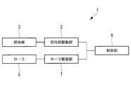
成形装置1は、図1~図3に示すように、把持部駆動部2と、把持部3と、マンドレル4と、ローラ5などを備える。また、図5に示すように、成形装置1は、制御部6と、ローラ駆動部7を更に備える。
As shown in FIGS. 1 to 3, the molding apparatus 1 includes a grip portion driving unit 2, a grip portion 3, a mandrel 4, a roller 5, and the like. Further, as shown in FIG. 5, the molding apparatus 1 further includes a control unit 6 and a roller drive unit 7.
図1~図3に示すように、マンドレル4は、断面が円弧形状を有し、円弧面にプリプレグなどの強化繊維シート10が載置される。強化繊維シート10は、被成形材料の一例である。強化繊維シート10は、マンドレル4上でローラ5によって押圧されることで、マンドレル4の円弧面に沿った形状に賦形される。
As shown in FIGS. 1 to 3, the mandrel 4 has an arcuate cross section, and a reinforcing fiber sheet 10 such as a prepreg is placed on the arcuate surface. The reinforcing fiber sheet 10 is an example of a material to be molded. The reinforcing fiber sheet 10 is pressed by the roller 5 on the mandrel 4 to form a shape along the arc surface of the mandrel 4.
ローラ5は、断面が円形状を有し、マンドレル4の表面に沿って転動しながら移動可能である。ローラ5は、マンドレル4に載置された強化繊維シート10に対して押圧力を付与する。ローラ5は、マンドレル4の円の中心を通過する鉛直線(中心線)を中心にして、左右に一つずつ合計二つ設置される。
The roller 5 has a circular cross section and can move while rolling along the surface of the mandrel 4. The roller 5 applies a pressing force to the reinforcing fiber sheet 10 placed on the mandrel 4. A total of two rollers 5 are installed on each side of the vertical straight line (center line) passing through the center of the circle of the mandrel 4.
把持部3は、マンドレル4に対してローラ5よりも外側で強化繊維シート10を把持する。また、把持部3は、強化繊維シート10に対して引っ張り力を付与する。把持部3は、マンドレル4の鉛直線(中心線)を中心にして、左右に一つずつ合計二つ設置される。なお、ローラ5と把持部3は、いずれも、後述するとおり、ローラ5の位置と把持部3の位置を同期させることができれば、それぞれ二つ以上設置されてもよい。把持部3によって、マンドレル4に沿って賦形される前のローラ5と把持部3との間の強化繊維シート10に対して引っ張り力が付与される。これにより、ローラ5に沿って被成形材料が確実に配置されるため、ローラ5の移動によるローラ5の位置の違いに関わらず、ローラ5と接している強化繊維シート10の周長差がゼロになる。
The grip portion 3 grips the reinforcing fiber sheet 10 on the outer side of the roller 5 with respect to the mandrel 4. Further, the grip portion 3 applies a tensile force to the reinforcing fiber sheet 10. A total of two grips 3 are installed, one on each side, about the vertical line (center line) of the mandrel 4. As will be described later, two or more rollers 5 and the grip portion 3 may be installed as long as the position of the roller 5 and the position of the grip portion 3 can be synchronized. The grip portion 3 applies a tensile force to the reinforcing fiber sheet 10 between the roller 5 and the grip portion 3 before being shaped along the mandrel 4. As a result, the material to be molded is surely arranged along the roller 5, so that the difference in the peripheral length of the reinforcing fiber sheet 10 in contact with the roller 5 is zero regardless of the difference in the position of the roller 5 due to the movement of the roller 5. become.
ローラ駆動部7は、ローラ5をマンドレル4の表面に沿って移動させる構成を有する。ローラ駆動部7は、制御部6から受信する駆動信号に基づいて、ローラ5の位置を調整する。
The roller drive unit 7 has a configuration in which the roller 5 is moved along the surface of the mandrel 4. The roller drive unit 7 adjusts the position of the roller 5 based on the drive signal received from the control unit 6.
把持部駆動部2は、把持部3をマンドレル4の鉛直線に対して平行方向、すなわち、上下方向に移動させる。把持部駆動部2は、制御部6から受信する駆動信号に基づいて、把持部3の位置を調整する。把持部駆動部2は、各把持部3に対して一つずつ設けられる。
The grip portion drive unit 2 moves the grip portion 3 in a direction parallel to the vertical line of the mandrel 4, that is, in the vertical direction. The grip unit drive unit 2 adjusts the position of the grip unit 3 based on the drive signal received from the control unit 6. One grip portion driving unit 2 is provided for each grip portion 3.
制御部6は、ローラ5の位置と把持部3の位置を同期させて、ローラ5と把持部3との間の強化繊維シート10が、マンドレル4の鉛直方向に対して垂直方向、すなわち、水平方向に配置されるように、ローラ駆動部7と把持部駆動部2を制御する。制御部6は、ローラ駆動部7の移動に関する駆動信号を生成して、ローラ駆動部7に駆動信号を送信する。また、制御部6は、把持部駆動部2の移動に関する駆動信号を生成して、把持部駆動部2の移動に関する駆動信号を送信する。
The control unit 6 synchronizes the position of the roller 5 with the position of the grip portion 3, so that the reinforcing fiber sheet 10 between the roller 5 and the grip portion 3 is perpendicular to the vertical direction of the mandrel 4, that is, horizontal. The roller drive unit 7 and the grip unit drive unit 2 are controlled so as to be arranged in the direction. The control unit 6 generates a drive signal related to the movement of the roller drive unit 7 and transmits the drive signal to the roller drive unit 7. Further, the control unit 6 generates a drive signal related to the movement of the grip unit drive unit 2 and transmits a drive signal related to the movement of the grip unit drive unit 2.
次に、本実施形態に係る成形装置1の動作について説明する。
まず、図1に示すように、強化繊維シート10が水平方向に配置されるように把持部3によって把持される。そして、把持部駆動部2が把持部3を下方向に移動させ、強化繊維シート10をマンドレル4上に配置する。このとき、把持部3は、強化繊維シート10に対して引っ張り力を付与する。 Next, the operation of themolding apparatus 1 according to the present embodiment will be described.
First, as shown in FIG. 1, the reinforcingfiber sheet 10 is gripped by the grip portion 3 so as to be arranged in the horizontal direction. Then, the grip portion driving unit 2 moves the grip portion 3 downward, and the reinforcing fiber sheet 10 is arranged on the mandrel 4. At this time, the grip portion 3 applies a tensile force to the reinforcing fiber sheet 10.
まず、図1に示すように、強化繊維シート10が水平方向に配置されるように把持部3によって把持される。そして、把持部駆動部2が把持部3を下方向に移動させ、強化繊維シート10をマンドレル4上に配置する。このとき、把持部3は、強化繊維シート10に対して引っ張り力を付与する。 Next, the operation of the
First, as shown in FIG. 1, the reinforcing
そして、図2に示すように、ローラ駆動部7がローラ5をマンドレル4の中心から外側へ向かってマンドレル4の表面に沿って移動させる。このとき、ローラ5は、強化繊維シート10に対して押圧力を付与する。これにより、強化繊維シート10がマンドレル4の最上端から下方へ向かって徐々に曲げられてマンドレル4の形状に沿った形に賦形される。なお、ローラ5による賦形を開始するとき、すなわち、マンドレル4の最上端において、ローラ5は、二つではなく、一つのみを用いて賦形を行ってもよい。熱可塑性樹脂を用いたCFRPの成形品を形成する場合、ローラ5による押圧では、強化繊維シート10を曲げつつ、強化繊維シート10を冷却させてもよい。
Then, as shown in FIG. 2, the roller drive unit 7 moves the roller 5 from the center of the mandrel 4 to the outside along the surface of the mandrel 4. At this time, the roller 5 applies a pressing force to the reinforcing fiber sheet 10. As a result, the reinforcing fiber sheet 10 is gradually bent downward from the uppermost end of the mandrel 4 to form a shape that follows the shape of the mandrel 4. It should be noted that when the shaping by the roller 5 is started, that is, at the uppermost end of the mandrel 4, the shaping may be performed using only one roller 5 instead of two. When forming a CFRP molded product using a thermoplastic resin, the reinforcing fiber sheet 10 may be cooled while bending the reinforcing fiber sheet 10 by pressing with the roller 5.
強化繊維シート10の端部までローラ5による賦形が完了すると、図3に示すように、把持部3による強化繊維シート10の把持が解除される。そして、ローラ5は、強化繊維シート10の端部をマンドレル4に沿って変形させる。
When the shaping by the roller 5 is completed up to the end of the reinforcing fiber sheet 10, the gripping portion 3 releases the gripping of the reinforcing fiber sheet 10 as shown in FIG. Then, the roller 5 deforms the end portion of the reinforcing fiber sheet 10 along the mandrel 4.
上述した賦形時において、ローラ5の位置と把持部3の位置を同期させて、ローラ5と把持部3の間の強化繊維シート10が常に水平方向となるように調整される。
At the time of shaping described above, the position of the roller 5 and the position of the grip portion 3 are synchronized so that the reinforcing fiber sheet 10 between the roller 5 and the grip portion 3 is always adjusted to be in the horizontal direction.
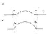
上記方法によって強化繊維シート10を賦形させる場合、図4に示すように、ある微小な時間間隔ΔTにおいて層間すべりが生じる領域は、例えば図4の領域10aのみとなる。図4では、図4(A)に示した時刻t=T1における領域10aが、図4(B)に示した時刻t=T1+ΔTにおいてマンドレル4上で賦形されていることを示している。したがって、ある微小な時間間隔ΔTにおいて層間すべりが生じる領域が局所的に抑えられる。
When the reinforcing fiber sheet 10 is shaped by the above method, as shown in FIG. 4, the region where inter-slip occurs at a certain minute time interval ΔT is, for example, only the region 10a in FIG. FIG. 4 shows that the region 10a at time t = T1 shown in FIG. 4 (A) is shaped on the mandrel 4 at time t = T1 + ΔT shown in FIG. 4 (B). Therefore, the region where inter-slip occurs is locally suppressed at a certain minute time interval ΔT.
以下、図6~図8を参照して、層間すべりが生じる領域が局所的になることについて詳細に説明する。図7及び図8は、図6の部分拡大図である。
ローラ5の位置と把持部3の位置が調整され、ローラ5と把持部3との間の強化繊維シート10が、マンドレル4の鉛直方向に対して垂直方向、すなわち、水平方向に配置されるため、賦形開始からある時刻T1までの間においてマンドレル4に沿って賦形された強化繊維シート10の周長差と、ある時刻T1においてローラ5に沿って配置された強化繊維シート10の周長差は等しい。 Hereinafter, with reference to FIGS. 6 to 8, it will be described in detail that the region where the interlayer slip occurs becomes local. 7 and 8 are partially enlarged views of FIG.
Since the position of theroller 5 and the position of the grip portion 3 are adjusted, the reinforcing fiber sheet 10 between the roller 5 and the grip portion 3 is arranged in the direction perpendicular to the vertical direction of the mandrel 4, that is, in the horizontal direction. , The difference in the circumference of the reinforcing fiber sheet 10 shaped along the mandrel 4 from the start of shaping to a certain time T1, and the circumference of the reinforcing fiber sheet 10 arranged along the roller 5 at a certain time T1. The difference is equal.
ローラ5の位置と把持部3の位置が調整され、ローラ5と把持部3との間の強化繊維シート10が、マンドレル4の鉛直方向に対して垂直方向、すなわち、水平方向に配置されるため、賦形開始からある時刻T1までの間においてマンドレル4に沿って賦形された強化繊維シート10の周長差と、ある時刻T1においてローラ5に沿って配置された強化繊維シート10の周長差は等しい。 Hereinafter, with reference to FIGS. 6 to 8, it will be described in detail that the region where the interlayer slip occurs becomes local. 7 and 8 are partially enlarged views of FIG.
Since the position of the
ここで、マンドレル4における強化繊維シート10の周長差とは、賦形開始からある時刻T1までの間においてマンドレル4と接している強化繊維シート10のマンドレル4側(内面側)の長さ(図7の領域Aの一点鎖線部)と、マンドレル4とは反対側(外面側)の長さ(図7の領域Aの二点鎖線部)の差である。マンドレル4における強化繊維シート10の周長差は、マンドレル4の径と強化繊維シート10の板厚tによって生じ、下記の式(1)によって表される。ここで、Rはマンドレル4の半径であり、θは時刻T1におけるマンドレル4の鉛直線と、マンドレル4の中心とローラ5の中心を結ぶ線とのなす角である。
Here, the difference in the peripheral length of the reinforcing fiber sheet 10 in the mandrel 4 is the length of the mandrel 4 side (inner surface side) of the reinforcing fiber sheet 10 in contact with the mandrel 4 from the start of shaping to a certain time T1. This is the difference between the length (the alternate long and short dash line portion of the region A in FIG. 7) and the length (the alternate long and short dash line portion of the region A in FIG. 7) opposite to the mandrel 4. The difference in the peripheral length of the reinforcing fiber sheet 10 in the mandrel 4 is caused by the diameter of the mandrel 4 and the plate thickness t of the reinforcing fiber sheet 10, and is represented by the following formula (1). Here, R is the radius of the mandrel 4, and θ is the angle formed by the vertical line of the mandrel 4 at time T1 and the line connecting the center of the mandrel 4 and the center of the roller 5.

また、ローラ5における強化繊維シート10の周長差とは、ある時刻T1においてローラ5と接している強化繊維シート10のローラ5側(内面側)の長さ(図7の領域Bの太実線部)と、ローラ5とは反対側(外面側)の長さ(図7の領域Bの破線部)の差である。ローラ5における強化繊維シート10の周長差は、ローラ5の径と強化繊維シート10の板厚tによって生じ、下記の式(2)によって表される。ここで、rはローラ5の半径である。
Further, the difference in the peripheral length of the reinforcing fiber sheet 10 in the roller 5 is the length of the reinforcing fiber sheet 10 in contact with the roller 5 at a certain time T1 on the roller 5 side (inner surface side) (thick solid line in the region B in FIG. 7). This is the difference between the length (the portion) and the length (the broken line portion of the region B in FIG. 7) on the side opposite to the roller 5 (outer surface side). The difference in the peripheral length of the reinforcing fiber sheet 10 in the roller 5 is caused by the diameter of the roller 5 and the plate thickness t of the reinforcing fiber sheet 10, and is represented by the following formula (2). Here, r is the radius of the roller 5.

すなわち、マンドレル4に沿って賦形された強化繊維シート10(図7の領域A)で生じる周長差(式(1))は、ローラ5に沿って配置された強化繊維シート10(図7の領域B)で生じている周長差でキャンセルされるため、ある時刻T1において、強化繊維シート10全体の周長差はゼロとなって、相殺されている。
That is, the difference in circumference (formula (1)) that occurs in the reinforcing fiber sheet 10 (region A in FIG. 7) shaped along the mandrel 4 is the reinforcing fiber sheet 10 (FIG. 7) arranged along the roller 5. Since it is canceled by the circumference difference occurring in the region B), the circumference difference of the entire reinforcing fiber sheet 10 becomes zero at a certain time T1 and is offset.
また、賦形開始からある時刻T1までの間においてマンドレル4に沿って賦形された強化繊維シート10(図8の領域A)の周長差と、賦形時におけるある微小な時間間隔ΔTでの強化繊維シート10(図8の領域C)で生じる周長差が等しい。
Further, the difference in the circumference of the reinforcing fiber sheet 10 (region A in FIG. 8) shaped along the mandrel 4 from the start of shaping to a certain time T1 and a certain minute time interval ΔT at the time of shaping are used. The difference in circumference generated in the reinforcing fiber sheet 10 (region C in FIG. 8) is equal.
ここで、マンドレル4に沿って賦形された強化繊維シート10の周長差とは、賦形開始からある時刻T1までの間においてマンドレル4と接している強化繊維シート10のマンドレル4側(内面側)の長さ(図8の領域Aの一点鎖線部)とマンドレル4とは反対側(外面側)の長さ(図8の領域Aの二点鎖線部)の差である。
Here, the difference in peripheral length of the reinforcing fiber sheet 10 shaped along the mandrel 4 is the mandrel 4 side (inner surface) of the reinforcing fiber sheet 10 in contact with the mandrel 4 from the start of shaping to a certain time T1. This is the difference between the length of the side) (the alternate long and short dash line portion of the region A in FIG. 8) and the length of the opposite side (outer surface side) of the mandrel 4 (the alternate long and short dash line portion of the region A of FIG. 8).
すでに賦形されている強化繊維シート10(図8の領域A)の周長差は、上記の式(1)で表される。
The difference in circumference of the already shaped reinforcing fiber sheet 10 (region A in FIG. 8) is represented by the above formula (1).
また、賦形時におけるある微小な時間間隔ΔTでの強化繊維シート10(図8の領域C)で生じる周長差とは、ある微小な時間間隔ΔTでローラ5が接する強化繊維シート10のローラ5側(内面側)の長さ(図8の領域Cの太実線部)と、ローラ5とは反対側(外面側)の長さ(図8の領域Cの破線部)の差である。
Further, the peripheral length difference that occurs in the reinforcing fiber sheet 10 (region C in FIG. 8) at a certain minute time interval ΔT at the time of shaping is the roller of the reinforcing fiber sheet 10 that the roller 5 contacts at a certain minute time interval ΔT. This is the difference between the length on the 5 side (inner surface side) (thick solid line portion of the region C in FIG. 8) and the length on the side opposite to the roller 5 (outer surface side) (broken line portion in the region C in FIG. 8).
賦形時におけるある微小な時間間隔ΔTで生じる周長差(図8の領域C)は、下記の式(3)で表される。ここで、Δθは、微小な時間間隔ΔTにおける、マンドレル4の鉛直線と、マンドレル4の中心とローラ5の中心を結ぶ線とのなす角の変化量である。
The circumference difference (region C in FIG. 8) that occurs at a minute time interval ΔT at the time of shaping is represented by the following equation (3). Here, Δθ is the amount of change in the angle formed by the vertical line of the mandrel 4 and the line connecting the center of the mandrel 4 and the center of the roller 5 at a minute time interval ΔT.

すなわち、周長差の差は、すでに賦形されている強化繊維シート10の周長差とある微小な時間間隔ΔTで賦形される強化繊維シート10の周長差が等しいため、ゼロになる(相殺される)。
That is, the difference in the circumference is zero because the difference in the circumference of the reinforcing fiber sheet 10 that has already been shaped is equal to the difference in the circumference of the reinforcing fiber sheet 10 that is shaped at a small time interval ΔT. (Offset).
以上より、(1)ある時刻T1において、強化繊維シート10全体の周長差は相殺される。(2)ある時刻T1までにすでに賦形されている強化繊維シート10(図8の領域A)の周長差は、ある微小な時間間隔ΔTで賦形される強化繊維シート10の周長差と等しく、相殺される。したがって、ある微小な時間間隔ΔTで賦形される強化繊維シート10のみで層間すべりが生じている。一方、これから賦形される未賦形の強化繊維シート10では層間すべりが生じていない。よって、ある時刻T1から時刻T1+ΔTの時間変化の際に生じる層間すべりは、ローラ5が通過した局所的な領域で起こっている。
From the above, (1) at a certain time T1, the difference in the circumference of the entire reinforcing fiber sheet 10 is offset. (2) The peripheral length difference of the reinforcing fiber sheet 10 (region A in FIG. 8) already formed by a certain time T1 is the peripheral length difference of the reinforcing fiber sheet 10 formed by a certain minute time interval ΔT. Is equal to and offset. Therefore, inter-slip occurs only in the reinforcing fiber sheet 10 shaped at a certain minute time interval ΔT. On the other hand, in the unformulated reinforcing fiber sheet 10 to be shaped from now on, inter-slip does not occur. Therefore, the inter-slip that occurs when the time changes from a certain time T1 to the time T1 + ΔT occurs in the local region through which the roller 5 has passed.
以上、本実施形態によれば、胴体スキンのような大型構造物を形成する場合であっても、強化繊維シートの全面にわたって層間すべりを生じさせる従来の方法と異なり、局所的に層間すべりが生じることから、リンクル等の発生を防止又は低減でき、品質低下リスクを低減できる。また、長時間かけて賦形する必要がないため、効率良く賦形を行うことができる。
As described above, according to the present embodiment, even when a large structure such as a body skin is formed, the interlayer slip occurs locally unlike the conventional method of causing the interlayer slip over the entire surface of the reinforcing fiber sheet. Therefore, the occurrence of wrinkles and the like can be prevented or reduced, and the risk of quality deterioration can be reduced. Moreover, since it is not necessary to shape the shape over a long period of time, the shape can be efficiently performed.
以上説明した実施形態に記載の成形装置は例えば以下のように把握される。
本開示に係る成形装置(1)は、断面が円弧形状を有するマンドレル(4)と、断面が円形状を有し、前記マンドレルの表面に沿って移動可能であり、前記マンドレルに載置された被成形材料(10)に対して押圧力を付与するローラ(5)と、前記マンドレルに対して前記ローラよりも外側で前記被成形材料を把持し、前記被成形材料に対して引っ張り力を付与する把持部(3)と、前記ローラを前記マンドレルの表面に沿って移動させるローラ駆動部(7)と、前記把持部を移動させる把持部駆動部(2)と、前記ローラの位置と前記把持部の位置を同期させて、前記ローラと前記把持部との間の前記被成形材料が、前記マンドレルの鉛直方向に対して垂直方向に配置されるように、前記ローラ駆動部と前記把持部駆動部を制御する制御部(6)とを備える。 The molding apparatus described in the above-described embodiment is grasped as follows, for example.
The molding apparatus (1) according to the present disclosure includes a mandrel (4) having an arc-shaped cross section and a mandrel having a circular cross-section, which can move along the surface of the mandrel and is placed on the mandrel. A roller (5) that applies a pressing force to the material to be molded (10) and a mandrel that grips the material to be molded outside the roller and applies a tensile force to the material to be molded. The grip portion (3), the roller drive portion (7) that moves the roller along the surface of the mandrel, the grip portion drive portion (2) that moves the grip portion, the position of the roller, and the grip. The roller drive portion and the grip portion drive so that the material to be formed between the roller and the grip portion is arranged in a direction perpendicular to the vertical direction of the mandrel by synchronizing the positions of the portions. A control unit (6) for controlling the unit is provided.
この構成によれば、被成形材料が把持部によって引っ張られながら、マンドレルとローラによって賦形される。ローラは、マンドレルの表面に沿って移動し、把持部は、ローラと同期しながら移動する。このとき、ローラ駆動部と把持部駆動部が制御されて、ローラと把持部との間の被成形材料が、マンドレルの鉛直方向に対して垂直方向に配置されるように、ローラの位置と把持部の位置が調整される。
According to this configuration, the material to be molded is shaped by the mandrel and the roller while being pulled by the grip. The rollers move along the surface of the mandrel, and the grip moves in synchronization with the rollers. At this time, the position and grip of the roller are controlled so that the roller drive portion and the grip portion drive portion are controlled so that the material to be molded between the roller and the grip portion is arranged in the direction perpendicular to the vertical direction of the mandrel. The position of the part is adjusted.
このように、ローラの位置と把持部の位置が調整され、ローラと把持部との間の被成形材料が、マンドレルの鉛直方向に対して垂直方向、すなわち、水平方向に配置されるため、賦形開始からある時刻T1までの間においてマンドレルに沿って賦形された被成形材料の周長差と、ある時刻T1におけるローラに沿って配置された被成形材料の周長差は等しい。ここで、マンドレルにおける被成形材料の周長差とは、マンドレルと接している被成形材料のマンドレル側(内面側)の長さとマンドレルとは反対側(外面側)の長さの差である。また、ローラにおける被成形材料の周長差とは、ローラと接している被成形材料のローラ側(内面側)の長さとローラとは反対側(外面側)の長さの差である。すなわち、マンドレルに沿って賦形された被成形材料で生じる周長差は、ローラに沿って配置された被成形材料で生じている周長差でキャンセルされるため、ある時刻T1において、被成形材料全体の周長差はゼロとなっている。
In this way, the position of the roller and the position of the grip portion are adjusted, and the material to be molded between the roller and the grip portion is arranged in the direction perpendicular to the vertical direction of the mandrel, that is, in the horizontal direction. The difference in the circumference of the material to be molded along the mandrel from the start of the shape to a certain time T1 is equal to the difference in the circumference of the material to be molded along the roller at a certain time T1. Here, the difference in the peripheral length of the material to be molded in the mandrel is the difference between the length of the material to be molded in contact with the mandrel on the mandrel side (inner surface side) and the length on the side opposite to the mandrel (outer surface side). Further, the difference in the peripheral length of the material to be molded in the roller is the difference between the length of the material to be molded in contact with the roller on the roller side (inner surface side) and the length on the side opposite to the roller (outer surface side). That is, since the difference in circumference caused by the material to be molded along the mandrel is canceled by the difference in circumference caused by the material to be molded arranged along the roller, the difference in circumference caused by the material to be molded is canceled at a certain time T1. The circumference difference of the entire material is zero.
また、すでに賦形されている被成形材料の周長差と、ある微小な時間間隔において被成形材料で生じる周長差が等しい。すなわち、周長差の差は、すでに賦形されている被成形材料とある微小な時間間隔で賦形される被成形材料でゼロになる。したがって、ある微小な時間間隔で賦形される被成形材料のみで層間すべりが生じており、これから賦形される未賦形の被成形材料では層間すべりが生じていない。
Also, the difference in the circumference of the material to be molded that has already been shaped is equal to the difference in the circumference that occurs in the material to be molded at a certain minute time interval. That is, the difference in the circumference difference becomes zero between the material to be molded that has already been shaped and the material to be molded that is shaped at a certain minute time interval. Therefore, the interlayer slip occurs only in the material to be molded which is shaped at a certain minute time interval, and the interlayer slip does not occur in the unformulated material to be molded which will be shaped from now on.
本開示に係る成形装置において、前記把持部によって、前記マンドレルに沿って賦形される前の前記ローラと前記把持部との間の前記被成形材料に対して引っ張り力が付与されることが望ましい。
In the molding apparatus according to the present disclosure, it is desirable that the grip portion applies a tensile force to the material to be molded between the roller and the grip portion before being shaped along the mandrel. ..
この構成によれば、ローラに沿って被成形材料が確実に配置されるため、ローラの移動によるローラの位置の違いに関わらず、ローラと接している被成形材料の周長差がゼロになる。
According to this configuration, the material to be molded is surely arranged along the roller, so that the difference in the peripheral length of the material to be molded in contact with the roller becomes zero regardless of the difference in the position of the roller due to the movement of the roller. ..
本開示に係る成形装置において、賦形開始からある時刻までの間において前記マンドレルに沿って賦形された前記被成形材料の周長差と、前記ある時刻において前記ローラに沿って配置された前記被成形材料の周長差は等しいことが望ましい。
In the molding apparatus according to the present disclosure, the difference in perimeter of the material to be molded along the mandrel from the start of shaping to a certain time, and the above-mentioned arranged along the roller at the certain time. It is desirable that the difference in circumference of the material to be molded is equal.
この構成によれば、マンドレルに沿って賦形された被成形材料で生じる周長差は、ローラに沿って配置された被成形材料で生じている周長差でキャンセルされるため、ある時刻T1において、被成形材料全体の周長差はゼロとなっている。
According to this configuration, the circumference difference caused by the material to be molded along the mandrel is canceled by the circumference difference caused by the material to be molded along the roller, and therefore, at a certain time T1. In, the difference in the circumference of the entire material to be molded is zero.
本開示に係る成形装置において、賦形開始からある時刻までの間において前記マンドレルに沿って賦形された前記被成形材料の周長差と、賦形時におけるある微小な時間間隔で前記被成形材料において生じる周長差は等しいことが望ましい。
In the molding apparatus according to the present disclosure, the molding is performed with the difference in the perimeter of the material to be molded along the mandrel from the start of shaping to a certain time and the minute time interval at the time of shaping. It is desirable that the circumference differences that occur in the materials are equal.
この構成によれば、周長差の差は、すでに賦形されている被成形材料とある微小な時間間隔で賦形される被成形材料でゼロになる。したがって、ある微小な時間間隔で賦形される被成形材料のみで層間すべりが生じており、これから賦形される未賦形の被成形材料では層間すべりが生じていない。
According to this configuration, the difference in circumference difference becomes zero between the material to be molded that has already been shaped and the material to be molded that is shaped at a certain minute time interval. Therefore, the interlayer slip occurs only in the material to be molded which is shaped at a certain minute time interval, and the interlayer slip does not occur in the unformulated material to be molded which will be shaped from now on.
本開示に係る成形方法は、断面が円弧形状を有するマンドレルと、断面が円形状を有し、前記マンドレルの表面に沿って移動可能であり、前記マンドレルに載置された被成形材料に対して押圧力を付与するローラと、前記マンドレルに対して前記ローラよりも外側で前記被成形材料を把持し、前記被成形材料に対して引っ張り力を付与する把持部と、前記ローラを前記マンドレルの表面に沿って移動させるローラ駆動部と、前記把持部を移動させる把持部駆動部とを備える成形装置を用いた成形方法であって、前記ローラが前記マンドレルに載置された前記被成形材料に対して押圧力を付与するステップと、前記把持部が前記被成形材料に対して引っ張り力を付与するステップと、前記ローラを前記マンドレルの表面に沿って移動させるステップと、前記把持部を移動させるステップと、前記ローラの位置と前記把持部の位置を同期させて、前記ローラと前記把持部との間の前記被成形材料を、前記マンドレルの鉛直方向に対して垂直方向に配置させるステップとを有する。
The molding method according to the present disclosure relates to a mandrel having an arc-shaped cross section and a material to be molded which has a circular cross-section and can move along the surface of the mandrel and is placed on the mandrel. A roller that applies a pressing force, a grip portion that grips the material to be molded on the outside of the roller to the mandrel and applies a tensile force to the material to be molded, and the roller on the surface of the mandrel. A molding method using a molding apparatus including a roller driving portion that moves along the grip portion and a grip portion driving portion that moves the grip portion with respect to the material to be molded in which the roller is placed on the mandrel. A step of applying a pressing force, a step of applying a tensile force to the material to be molded by the grip portion, a step of moving the roller along the surface of the mandrel, and a step of moving the grip portion. And a step of synchronizing the position of the roller and the position of the grip portion to arrange the material to be molded between the roller and the grip portion in a direction perpendicular to the vertical direction of the mandrel. ..
1 :成形装置
2 :把持部駆動部
3 :把持部
4 :マンドレル
5 :ローラ
6 :制御部
7 :ローラ駆動部
10 :強化繊維シート
10a :領域
20 :積層体
1: Molding device 2: Grip part drive part 3: Grip part 4: Mandrel 5: Roller 6: Control part 7: Roller drive part 10: Reinforcingfiber sheet 10a: Region 20: Laminated body
2 :把持部駆動部
3 :把持部
4 :マンドレル
5 :ローラ
6 :制御部
7 :ローラ駆動部
10 :強化繊維シート
10a :領域
20 :積層体
1: Molding device 2: Grip part drive part 3: Grip part 4: Mandrel 5: Roller 6: Control part 7: Roller drive part 10: Reinforcing
Claims (5)
- 断面が円弧形状を有するマンドレルと、
断面が円形状を有し、前記マンドレルの表面に沿って移動可能であり、前記マンドレルに載置された被成形材料に対して押圧力を付与するローラと、
前記マンドレルに対して前記ローラよりも外側で前記被成形材料を把持し、前記被成形材料に対して引っ張り力を付与する把持部と、
前記ローラを前記マンドレルの表面に沿って移動させるローラ駆動部と、
前記把持部を移動させる把持部駆動部と、
前記ローラの位置と前記把持部の位置を同期させて、前記ローラと前記把持部との間の前記被成形材料が、前記マンドレルの鉛直方向に対して垂直方向に配置されるように、前記ローラ駆動部と前記把持部駆動部を制御する制御部と、
を備える成形装置。 A mandrel whose cross section has an arc shape,
A roller having a circular cross section, being movable along the surface of the mandrel, and applying a pressing force to the material to be molded placed on the mandrel.
A grip portion that grips the material to be molded on the outside of the roller with respect to the mandrel and applies a tensile force to the material to be molded.
A roller drive unit that moves the roller along the surface of the mandrel,
A grip portion driving unit that moves the grip portion and
The roller is synchronized with the position of the roller so that the material to be molded between the roller and the grip is arranged in a direction perpendicular to the vertical direction of the mandrel. A control unit that controls the drive unit and the grip unit drive unit,
A molding device equipped with. - 前記把持部によって、前記マンドレルに沿って賦形される前の前記ローラと前記把持部との間の前記被成形材料に対して引っ張り力が付与されている請求項1に記載の成形装置。 The molding apparatus according to claim 1, wherein a tensile force is applied to the material to be molded between the roller and the grip portion before being shaped along the mandrel by the grip portion.
- 賦形開始からある時刻までの間において前記マンドレルに沿って賦形された前記被成形材料の周長差と、前記ある時刻において前記ローラに沿って配置された前記被成形材料の周長差は等しい請求項1又は2に記載の成形装置。 The difference in the circumference of the material to be molded along the mandrel from the start of shaping to a certain time is the difference in the circumference of the material to be molded along the roller at the time. The molding apparatus according to claim 1 or 2.
- 賦形開始からある時刻までの間において前記マンドレルに沿って賦形された前記被成形材料の周長差と、賦形時におけるある微小な時間間隔で前記被成形材料において生じる周長差は等しい請求項1から3のいずれか1項に記載の成形装置。 The difference in the circumference of the material to be molded along the mandrel from the start of shaping to a certain time is equal to the difference in the circumference of the material to be molded at a certain minute time interval at the time of shaping. The molding apparatus according to any one of claims 1 to 3.
- 断面が円弧形状を有するマンドレルと、断面が円形状を有し、前記マンドレルの表面に沿って移動可能であり、前記マンドレルに載置された被成形材料に対して押圧力を付与するローラと、前記マンドレルに対して前記ローラよりも外側で前記被成形材料を把持し、前記被成形材料に対して引っ張り力を付与する把持部と、前記ローラを前記マンドレルの表面に沿って移動させるローラ駆動部と、前記把持部を移動させる把持部駆動部とを備える成形装置を用いた成形方法であって、
前記ローラが前記マンドレルに載置された前記被成形材料に対して押圧力を付与するステップと、
前記把持部が前記被成形材料に対して引っ張り力を付与するステップと、
前記ローラを前記マンドレルの表面に沿って移動させるステップと、
前記把持部を移動させるステップと、
前記ローラの位置と前記把持部の位置を同期させて、前記ローラと前記把持部との間の前記被成形材料を、前記マンドレルの鉛直方向に対して垂直方向に配置させるステップと、
を有する成形方法。
A mandrel having an arc-shaped cross section, a roller having a circular cross-section, being movable along the surface of the mandrel, and applying a pressing force to a material to be molded placed on the mandrel. A grip portion that grips the material to be molded on the outside of the roller with respect to the mandrel and applies a tensile force to the material to be molded, and a roller drive unit that moves the roller along the surface of the mandrel. A molding method using a molding apparatus including a grip portion driving portion for moving the grip portion.
A step in which the roller applies a pressing force to the material to be molded placed on the mandrel, and
A step in which the grip portion applies a tensile force to the material to be molded,
A step of moving the roller along the surface of the mandrel,
The step of moving the grip portion and
A step of synchronizing the position of the roller and the position of the grip portion to arrange the material to be molded between the roller and the grip portion in a direction perpendicular to the vertical direction of the mandrel.
Molding method having.
Priority Applications (4)
| Application Number | Priority Date | Filing Date | Title |
|---|---|---|---|
| JP2021555636A JP7187712B2 (en) | 2019-11-11 | 2019-11-11 | Molding device and molding method |
| EP19952278.0A EP4000862A4 (en) | 2019-11-11 | 2019-11-11 | Molding device and molding method |
| US17/634,861 US20220324156A1 (en) | 2019-11-11 | 2019-11-11 | Molding device and molding method |
| PCT/JP2019/044150 WO2021095097A1 (en) | 2019-11-11 | 2019-11-11 | Molding device and molding method |
Applications Claiming Priority (1)
| Application Number | Priority Date | Filing Date | Title |
|---|---|---|---|
| PCT/JP2019/044150 WO2021095097A1 (en) | 2019-11-11 | 2019-11-11 | Molding device and molding method |
Publications (1)
| Publication Number | Publication Date |
|---|---|
| WO2021095097A1 true WO2021095097A1 (en) | 2021-05-20 |
Family
ID=75911909
Family Applications (1)
| Application Number | Title | Priority Date | Filing Date |
|---|---|---|---|
| PCT/JP2019/044150 WO2021095097A1 (en) | 2019-11-11 | 2019-11-11 | Molding device and molding method |
Country Status (4)
| Country | Link |
|---|---|
| US (1) | US20220324156A1 (en) |
| EP (1) | EP4000862A4 (en) |
| JP (1) | JP7187712B2 (en) |
| WO (1) | WO2021095097A1 (en) |
Citations (4)
| Publication number | Priority date | Publication date | Assignee | Title |
|---|---|---|---|---|
| JPS6368226A (en) * | 1986-09-08 | 1988-03-28 | Nippon Spindle Mfg Co Ltd | Driving device for spinning machine |
| JPH01139236A (en) * | 1987-11-26 | 1989-05-31 | Yazaki Kako Kk | Bending method for thermoplastic synthetic resin corrugated sheet |
| JP2016120605A (en) * | 2014-12-24 | 2016-07-07 | スリーエム イノベイティブ プロパティズ カンパニー | Sticking method and film |
| US10166729B2 (en) | 2014-12-22 | 2019-01-01 | Airbus Defence and Space GmbH | Device for consolidating a preform |
Family Cites Families (5)
| Publication number | Priority date | Publication date | Assignee | Title |
|---|---|---|---|---|
| GB784997A (en) * | 1954-11-03 | 1957-10-23 | Nat Res Dev | Improvements in or relating to the stretching and forming of metal sheet or slab |
| JPS466345B1 (en) * | 1967-04-13 | 1971-02-17 | ||
| GB8719495D0 (en) * | 1987-08-18 | 1987-09-23 | Abbeybench Ltd | Forming parts from ductile materials |
| JPH06412Y2 (en) * | 1988-03-30 | 1994-01-05 | セントラル硝子株式会社 | Bending machine |
| US6474975B2 (en) * | 1998-03-27 | 2002-11-05 | Coachmen Industries, Inc. | Press mechanism |
-
2019
- 2019-11-11 WO PCT/JP2019/044150 patent/WO2021095097A1/en unknown
- 2019-11-11 JP JP2021555636A patent/JP7187712B2/en active Active
- 2019-11-11 EP EP19952278.0A patent/EP4000862A4/en active Pending
- 2019-11-11 US US17/634,861 patent/US20220324156A1/en active Pending
Patent Citations (4)
| Publication number | Priority date | Publication date | Assignee | Title |
|---|---|---|---|---|
| JPS6368226A (en) * | 1986-09-08 | 1988-03-28 | Nippon Spindle Mfg Co Ltd | Driving device for spinning machine |
| JPH01139236A (en) * | 1987-11-26 | 1989-05-31 | Yazaki Kako Kk | Bending method for thermoplastic synthetic resin corrugated sheet |
| US10166729B2 (en) | 2014-12-22 | 2019-01-01 | Airbus Defence and Space GmbH | Device for consolidating a preform |
| JP2016120605A (en) * | 2014-12-24 | 2016-07-07 | スリーエム イノベイティブ プロパティズ カンパニー | Sticking method and film |
Non-Patent Citations (2)
| Title |
|---|
| CENTRAL GLASS CO., LTD.: "Microfilm of the specification and drawings annexed to the request of Japanese Utility Model Application No. 42560/1988", LAID-OPEN NO. 147227/1989, 11 October 1989 (1989-10-11) * |
| See also references of EP4000862A4 |
Also Published As
| Publication number | Publication date |
|---|---|
| JP7187712B2 (en) | 2022-12-12 |
| EP4000862A1 (en) | 2022-05-25 |
| US20220324156A1 (en) | 2022-10-13 |
| EP4000862A4 (en) | 2022-08-03 |
| JPWO2021095097A1 (en) | 2021-05-20 |
Similar Documents
| Publication | Publication Date | Title |
|---|---|---|
| JP3400399B2 (en) | Continuous molding equipment for F-shaped H-shaped members | |
| US20080053599A1 (en) | Method for continuously preforming composite material in uncured state | |
| EP1547753A1 (en) | Method and apparatus for molding thermosetting composite material | |
| JP2005059260A (en) | Method and apparatus for continuously forming fiber reinforced plastic member having curvature | |
| JP3862697B2 (en) | Thermosetting composite material molding equipment | |
| JP6411677B1 (en) | Manufacturing method of composite material part and composite material part manufacturing apparatus | |
| EP2995443B1 (en) | System and process for forming stacks of composite materials | |
| WO2021095097A1 (en) | Molding device and molding method | |
| EP2186627A2 (en) | Method for continuously forming composite material shape member having varied cross-sectional shape | |
| US5344602A (en) | Continuous forming of fiber composite materials | |
| JP3402481B2 (en) | Pre-preg material molding equipment | |
| CA2900003A1 (en) | A method and an apparatus for forming profile elements | |
| JP7039738B2 (en) | Laminate molding method and laminate molding equipment | |
| WO2021106070A1 (en) | Molding device, molding method, and fiber sheet laminate | |
| JP7124132B2 (en) | LAMINATED FORMING APPARATUS AND LAMINATED FORMING METHOD | |
| JP7358504B2 (en) | Molding method and mold | |
| JP7175820B2 (en) | Prepreg molding method | |
| EP3822068B1 (en) | Device and method for forming a composite laminate for obtaining a z-shaped profile | |
| EP4328013A1 (en) | Continuous molding machine |
Legal Events
| Date | Code | Title | Description |
|---|---|---|---|
| 121 | Ep: the epo has been informed by wipo that ep was designated in this application |
Ref document number: 19952278 Country of ref document: EP Kind code of ref document: A1 |
|
| ENP | Entry into the national phase |
Ref document number: 2021555636 Country of ref document: JP Kind code of ref document: A |
|
| ENP | Entry into the national phase |
Ref document number: 2019952278 Country of ref document: EP Effective date: 20220215 |
|
| NENP | Non-entry into the national phase |
Ref country code: DE |