WO2021089090A1 - Method and apparatus for processing an optically reactive material - Google Patents
Method and apparatus for processing an optically reactive material Download PDFInfo
- Publication number
- WO2021089090A1 WO2021089090A1 PCT/DE2020/100952 DE2020100952W WO2021089090A1 WO 2021089090 A1 WO2021089090 A1 WO 2021089090A1 DE 2020100952 W DE2020100952 W DE 2020100952W WO 2021089090 A1 WO2021089090 A1 WO 2021089090A1
- Authority
- WO
- WIPO (PCT)
- Prior art keywords
- light
- wavelength
- volume
- starting material
- layer
- Prior art date
Links
- 238000012545 processing Methods 0.000 title claims abstract description 63
- 238000000034 method Methods 0.000 title claims abstract description 44
- 239000000463 material Substances 0.000 title claims abstract description 36
- 239000007858 starting material Substances 0.000 claims abstract description 125
- 230000003287 optical effect Effects 0.000 claims abstract description 40
- 230000001678 irradiating effect Effects 0.000 claims abstract description 30
- 230000008569 process Effects 0.000 claims abstract description 11
- 238000006116 polymerization reaction Methods 0.000 claims description 15
- 238000009826 distribution Methods 0.000 claims description 13
- 230000001960 triggered effect Effects 0.000 claims description 5
- 230000008859 change Effects 0.000 claims description 4
- 230000002123 temporal effect Effects 0.000 claims description 4
- PLXMOAALOJOTIY-FPTXNFDTSA-N Aesculin Natural products OC[C@@H]1[C@@H](O)[C@H](O)[C@@H](O)[C@H](O)[C@H]1Oc2cc3C=CC(=O)Oc3cc2O PLXMOAALOJOTIY-FPTXNFDTSA-N 0.000 claims description 3
- 238000003672 processing method Methods 0.000 claims description 2
- 238000005286 illumination Methods 0.000 abstract description 2
- 239000003999 initiator Substances 0.000 description 15
- 238000010521 absorption reaction Methods 0.000 description 10
- 230000005284 excitation Effects 0.000 description 7
- 238000006243 chemical reaction Methods 0.000 description 6
- 230000033001 locomotion Effects 0.000 description 6
- 238000004519 manufacturing process Methods 0.000 description 5
- 239000000126 substance Substances 0.000 description 5
- 230000007704 transition Effects 0.000 description 5
- 238000006073 displacement reaction Methods 0.000 description 4
- 238000009825 accumulation Methods 0.000 description 3
- 239000000654 additive Substances 0.000 description 3
- 230000000694 effects Effects 0.000 description 3
- 229920000642 polymer Polymers 0.000 description 3
- 238000013519 translation Methods 0.000 description 3
- 238000010146 3D printing Methods 0.000 description 2
- 241000208140 Acer Species 0.000 description 2
- 230000000996 additive effect Effects 0.000 description 2
- 230000005540 biological transmission Effects 0.000 description 2
- 230000009977 dual effect Effects 0.000 description 2
- 230000005283 ground state Effects 0.000 description 2
- 239000007788 liquid Substances 0.000 description 2
- 238000005259 measurement Methods 0.000 description 2
- 238000012986 modification Methods 0.000 description 2
- 230000004048 modification Effects 0.000 description 2
- 235000011837 pasties Nutrition 0.000 description 2
- 230000005855 radiation Effects 0.000 description 2
- 239000007787 solid Substances 0.000 description 2
- 231100000987 absorbed dose Toxicity 0.000 description 1
- 230000006978 adaptation Effects 0.000 description 1
- QVGXLLKOCUKJST-UHFFFAOYSA-N atomic oxygen Chemical compound [O] QVGXLLKOCUKJST-UHFFFAOYSA-N 0.000 description 1
- 230000008901 benefit Effects 0.000 description 1
- 230000015572 biosynthetic process Effects 0.000 description 1
- 230000015556 catabolic process Effects 0.000 description 1
- 239000003795 chemical substances by application Substances 0.000 description 1
- 230000000295 complement effect Effects 0.000 description 1
- 238000012937 correction Methods 0.000 description 1
- 230000008878 coupling Effects 0.000 description 1
- 238000010168 coupling process Methods 0.000 description 1
- 238000005859 coupling reaction Methods 0.000 description 1
- 238000004132 cross linking Methods 0.000 description 1
- 238000006731 degradation reaction Methods 0.000 description 1
- 230000001419 dependent effect Effects 0.000 description 1
- 238000011156 evaluation Methods 0.000 description 1
- 230000005281 excited state Effects 0.000 description 1
- 239000011521 glass Substances 0.000 description 1
- 238000003384 imaging method Methods 0.000 description 1
- 238000007654 immersion Methods 0.000 description 1
- 230000002401 inhibitory effect Effects 0.000 description 1
- 230000005764 inhibitory process Effects 0.000 description 1
- 230000000977 initiatory effect Effects 0.000 description 1
- 239000007924 injection Substances 0.000 description 1
- 238000002347 injection Methods 0.000 description 1
- 230000031700 light absorption Effects 0.000 description 1
- 230000001404 mediated effect Effects 0.000 description 1
- 238000000465 moulding Methods 0.000 description 1
- 239000002086 nanomaterial Substances 0.000 description 1
- 239000005304 optical glass Substances 0.000 description 1
- 238000005457 optimization Methods 0.000 description 1
- 229910052760 oxygen Inorganic materials 0.000 description 1
- 239000001301 oxygen Substances 0.000 description 1
- 239000004033 plastic Substances 0.000 description 1
- 229920003023 plastic Polymers 0.000 description 1
- 230000000379 polymerizing effect Effects 0.000 description 1
- 230000002441 reversible effect Effects 0.000 description 1
- 238000007493 shaping process Methods 0.000 description 1
- 238000011144 upstream manufacturing Methods 0.000 description 1
Classifications
-
- B—PERFORMING OPERATIONS; TRANSPORTING
- B29—WORKING OF PLASTICS; WORKING OF SUBSTANCES IN A PLASTIC STATE IN GENERAL
- B29C—SHAPING OR JOINING OF PLASTICS; SHAPING OF MATERIAL IN A PLASTIC STATE, NOT OTHERWISE PROVIDED FOR; AFTER-TREATMENT OF THE SHAPED PRODUCTS, e.g. REPAIRING
- B29C64/00—Additive manufacturing, i.e. manufacturing of three-dimensional [3D] objects by additive deposition, additive agglomeration or additive layering, e.g. by 3D printing, stereolithography or selective laser sintering
- B29C64/10—Processes of additive manufacturing
- B29C64/106—Processes of additive manufacturing using only liquids or viscous materials, e.g. depositing a continuous bead of viscous material
- B29C64/124—Processes of additive manufacturing using only liquids or viscous materials, e.g. depositing a continuous bead of viscous material using layers of liquid which are selectively solidified
- B29C64/129—Processes of additive manufacturing using only liquids or viscous materials, e.g. depositing a continuous bead of viscous material using layers of liquid which are selectively solidified characterised by the energy source therefor, e.g. by global irradiation combined with a mask
- B29C64/135—Processes of additive manufacturing using only liquids or viscous materials, e.g. depositing a continuous bead of viscous material using layers of liquid which are selectively solidified characterised by the energy source therefor, e.g. by global irradiation combined with a mask the energy source being concentrated, e.g. scanning lasers or focused light sources
-
- B—PERFORMING OPERATIONS; TRANSPORTING
- B29—WORKING OF PLASTICS; WORKING OF SUBSTANCES IN A PLASTIC STATE IN GENERAL
- B29C—SHAPING OR JOINING OF PLASTICS; SHAPING OF MATERIAL IN A PLASTIC STATE, NOT OTHERWISE PROVIDED FOR; AFTER-TREATMENT OF THE SHAPED PRODUCTS, e.g. REPAIRING
- B29C64/00—Additive manufacturing, i.e. manufacturing of three-dimensional [3D] objects by additive deposition, additive agglomeration or additive layering, e.g. by 3D printing, stereolithography or selective laser sintering
- B29C64/10—Processes of additive manufacturing
- B29C64/106—Processes of additive manufacturing using only liquids or viscous materials, e.g. depositing a continuous bead of viscous material
- B29C64/124—Processes of additive manufacturing using only liquids or viscous materials, e.g. depositing a continuous bead of viscous material using layers of liquid which are selectively solidified
- B29C64/129—Processes of additive manufacturing using only liquids or viscous materials, e.g. depositing a continuous bead of viscous material using layers of liquid which are selectively solidified characterised by the energy source therefor, e.g. by global irradiation combined with a mask
-
- B—PERFORMING OPERATIONS; TRANSPORTING
- B29—WORKING OF PLASTICS; WORKING OF SUBSTANCES IN A PLASTIC STATE IN GENERAL
- B29C—SHAPING OR JOINING OF PLASTICS; SHAPING OF MATERIAL IN A PLASTIC STATE, NOT OTHERWISE PROVIDED FOR; AFTER-TREATMENT OF THE SHAPED PRODUCTS, e.g. REPAIRING
- B29C64/00—Additive manufacturing, i.e. manufacturing of three-dimensional [3D] objects by additive deposition, additive agglomeration or additive layering, e.g. by 3D printing, stereolithography or selective laser sintering
- B29C64/20—Apparatus for additive manufacturing; Details thereof or accessories therefor
- B29C64/264—Arrangements for irradiation
- B29C64/277—Arrangements for irradiation using multiple radiation means, e.g. micromirrors or multiple light-emitting diodes [LED]
-
- B—PERFORMING OPERATIONS; TRANSPORTING
- B33—ADDITIVE MANUFACTURING TECHNOLOGY
- B33Y—ADDITIVE MANUFACTURING, i.e. MANUFACTURING OF THREE-DIMENSIONAL [3-D] OBJECTS BY ADDITIVE DEPOSITION, ADDITIVE AGGLOMERATION OR ADDITIVE LAYERING, e.g. BY 3-D PRINTING, STEREOLITHOGRAPHY OR SELECTIVE LASER SINTERING
- B33Y10/00—Processes of additive manufacturing
-
- B—PERFORMING OPERATIONS; TRANSPORTING
- B33—ADDITIVE MANUFACTURING TECHNOLOGY
- B33Y—ADDITIVE MANUFACTURING, i.e. MANUFACTURING OF THREE-DIMENSIONAL [3-D] OBJECTS BY ADDITIVE DEPOSITION, ADDITIVE AGGLOMERATION OR ADDITIVE LAYERING, e.g. BY 3-D PRINTING, STEREOLITHOGRAPHY OR SELECTIVE LASER SINTERING
- B33Y30/00—Apparatus for additive manufacturing; Details thereof or accessories therefor
Definitions
- the invention relates to a method and an apparatus for processing an optically reactive material.
- Starting materials can be processed optically, that is to say by irradiating light of one or more wavelengths onto the starting material, in order to thereby change at least one material property of the starting material. For example, it is known as such to harden a starting material with the aid of such optical processing.
- Document US 2019/001 6052 A1 describes a method on a device for an additive method for producing three-dimensional bodies. It is provided here to arrange several LCD displays one above the other in order to use the LCD displays to display a three-dimensional image on a material to be cured.
- the LCD displays are positioned as layers in a stationary manner in a stacked arrangement.
- a UV-curable polymer is to be processed in this way.
- a method for producing a printable 3D nanostructure comprising: a first light source which is set up to bring a polymer medium into an excited state via a dynamic light space modulation element in order to initiate the polymerization to initiate; a second light source arranged to selectively apply inhibitory energy to the polymerized medium to inhibit the polymerization, thereby creating a dead zone beneath a growth zone which enables continuous 3-D polymerization.
- Document US 2019/160539 A1 discloses an additive manufacturing device comprising: a platform, a dispenser configured to deliver multiple successive layers of a feed material onto the platform, a light source array for generating a first light beam and a second light beam, a beam combiner configured to combine the first light and the second light into a common light beam, and a mirror scanner configured to direct the common light beam onto the platform, to deliver energy along a sensing path on an outermost layer of the feed material.
- Polymerization is a reaction that is used to make plastics.
- photopolymerization which is a form of optical processing of a starting material
- the reaction is triggered by irradiating light onto the polymerizable starting material.
- Such polymerizable starting substances or materials are also referred to as photopolymers.
- This is a polymer that changes its material properties when it is irradiated with light. The light irradiation causes structural changes, for example the photochemical hardening of the material through crosslinking.
- Photopolymerization is used, for example, in 3D printing to produce three-dimensional moldings from the cured material by means of light irradiation in the polymerizable starting material.
- the starting material itself can be transparent and therefore insensitive to the incident light.
- Photoinitiator molecules are added, which absorb the light and initiate the curing of the starting material.
- the addressing of a freely selected point in the 3-dimensional space is necessary.
- One possibility is the use of special len photo initiators, which are also referred to as dual-color photo initiators. These are preferably or exclusively excited by the absorption of photons of two different wavelengths.
- Dual-color photoinitiators can be generated in different ways; in one variant, molecules without light exposure have a basic / normal status (A). In this state, the molecule has an absorption band for a wavelength A-
- the molecules can then assume a pre-activated or excited intermediate state (B).
- the excited intermediate state is generated by absorption of light of the wavelength from the ground state A.
- the photoinitiator molecules have an absorption band for the wavelength k 2 .
- the absorption band for the wavelength disappears.
- the absorption band remains for the wavelength receive. This creates an undesirable, competing transition channel to state C.
- the photo initiation tor molecule returns to state A in the absence of light.
- the photoinitiator molecule returns to state A after excitation with light of a third wavelength ⁇ 3. This allows a targeted inhibition of the initiator in state B.
- the active state C of the molecules is generated by absorption of the wavelength ⁇ 2 from B.
- State C sets a chemical and / or a physical modification of the immediate environment of the molecule in motion.
- a reverse reaction to B is not intended but possible.
- the object of the invention is to provide a method and a device for processing an op table reactive material with which a starting material can be optically processed in an efficient manner in multiple dimensions.
- a method for processing an optically reactive material comprising: providing a starting material which is optically reactive and fills a working volume; and optical processing of the starting material in the working volume by irradiating light of a first wavelength and light of a second wavelength which is different from the first wavelength, the light of the first wavelength and the light of the second wavelength being provided by a lighting device and by means of the optical Editing at least one material property of the starting material is changed.
- the optical processing comprises the following: irradiating a first layer partial volume of the working volume filled with the starting material with the light of the first wavelength; Irradiating the first partial slice volume of the working volume with the light of the second wavelength, the light of the second wavelength being projected into the working volume by means of a projection device, covering only the first partial slice volume in whole or in part; Irradiating a second layer partial volume of the working volume filled with the starting material with the starting material, which is different from the first layer partial volume, with the light of the first wavelength; Irradiating the second slice partial volume of the working volume with the light of the second wavelength, the light of the second wavelength being projected into the working volume by means of the projection device, completely or partially capturing only the second slice volume; and repeating the preceding steps for layer-by-layer optical processing of the starting material in the working volume until a volume of the starting material to be processed, which completely or partially covers the working volume, has been optically processed.
- an apparatus for processing an optically reactive material comprising: a working volume which is set up to receive a starting material which is optically reactive and fills the working volume; Be a lighting device which is set up to provide light of a first wavelength and light of a second wavelength for irradiation on the working volume with the starting material; and a projection device which is set up to project the light of the second wavelength when it is irradiated onto the working volume filled with the starting material into a partial slice volume of the working volume and only partially or completely capturing the partial slice volume.
- the lighting device and the projection device are also set up to optically process the starting material in the working volume as follows: irradiating a first layer partial volume of the working volume filled with the starting material with the light of the first wavelength; Irradiating the first slice partial volume of the working volume with the light of the second wavelength, the light of the second wavelength being projected into the working volume by means of a projection device, covering only the first slice partial volume, in whole or in part; Irradiating a second partial volume of the layer of the working volume filled with the starting material with the starting material, which is different from the first partial volume of the layer, with the light of the first wavelength; Irradiating the second partial slice volume of the working volume with the light of the second wavelength, the light of the second wavelength being projected into the working volume in whole or in part by means of the projection device; and repeating the preceding steps for optical processing of the starting material in layers in the working volume until a volume of the starting material to be processed, which completely or partially covers the working volume, has been optically processed.
- the partial volume of the layer of the working volume is irradiated with the first and the second wavelength in order to trigger an optically initiated reaction in the starting material.
- the partial volume of the layers which are optically processed one after the other, contain partial volumes of the starting material that is introduced into the working volume before the start of the manufacturing process (optical processing), and are filled by these.
- optical processing there is no layer-by-layer application of the starting material and subsequent layer-by-layer optical processing (of the layer that has just been applied) after the layer application.
- the projection of the light of the second wavelength takes place with the help of the projection device in exactly this partial volume of the layer that is currently irradiated with the first wavelength.
- the projection device effects an image of the light of the second wavelength in the currently desired partial volume of the layer.
- the projection device can map the light of the second wavelength of an at least two-dimensionally shaped image into the projection plane or the projection volume, which is located in the partial volume of the layer irradiated with the light of the first wavelength. In this way, for example, a three-dimensional body can be produced in the starting material layer by layer.
- control device that is connected to one or more light sources for providing the light of the first and the light of the second wavelength as well as the projection device, it can be determined whether the first or the second layer partial volume (of the starting material in the working volume) is irradiated, and the The projection device can be controlled as a function of this to project the light of the second wavelength into the first or the second partial volume of the layer.
- the control device provides data which define the current or instantaneous position of the partial slice volume which is irradiated with light of the first wavelength.
- the projection device is controlled in such a way that the projection generated with the aid of the projection device in a projection plane or in a projection volume in this is up-to-date irradiated layer partial volume takes place.
- the layer sub-volumes of the starting material are processed layer by layer one after the other.
- the outer shape of the projection of the projection device can be different here for different layer partial volumes, in particular depending on a three-dimensional body that is to be produced in the starting material with the aid of optical processing.
- a current or momentary position of the slice partial volume which is irradiated with the light of the first wavelength, in the working volume to be detected with the help of a measuring device, which then gives the position indicating de measurement signals to the control device.
- the light of the first wavelength and the light of the second wavelength can be radiated simultaneously into the first or the second partial volume of the layer at least for a temporal overlap period.
- the area covered by the partial slice volume and the projection of the projection device is irradiated both with light of the first wavelength and with light of the second wavelength at least for the temporal overlap area.
- the first and the second layer partial volume can form adjacent layer partial volumes of the starting material in the working volume.
- first and the second layer partial volume are formed in accordance with one of the following configurations of partial volumes: the edges overlap, the edges abut and the edges are spaced apart from one another.
- the light of the first wavelength can be irradiated onto the starting material in the working volume along a first direction of irradiation and the light of the second wavelength can be irradiated along a second direction of irradiation which runs transversely to the first direction of irradiation.
- the first and the second direction of irradiation can assume an angle of approximately 90 °, for example. Other angles can be provided in the range from approximately 30 ° to 90 ° degrees between the optical axes of the radiation directions.
- the light of the first wavelength and / or the light of the second wavelength can be irradiated as pulsed light.
- the light pulses of light of the first and second wavelengths can enter the momentary at the same time or at a predetermined time interval one after the other processed slice volume are irradiated.
- the light pulses for the light at the wavelengths can be provided with the same or different temporal pulse widths.
- the light of the first wavelength or the light of the second wavelength can be irradiated as continuous light.
- the starting material can be processed by means of optical processing in accordance with at least one processing method from the following group: curing, hardening, gelling and liquefying.
- the starting material can be solid, liquid or pasty.
- the starting material is made to glow due to the optical processing with the light of the first and second wavelength, in particular due to fluorescence or phosphorescence.
- a layered irradiation region of a first light source can be displaced relative to the working volume.
- the layered irradiation area for the light of the first wavelength is shifted relative to this during the optical processing of the starting material, so that the irradiation area quasi runs or sweeps over the working volume.
- the relative movement between the working volume and the irradiation area can be implemented in various ways. A shift of the working volume and / or the first light source can be provided. Alternatively or in addition, the working volume and the first light source can be fixed relative to one another during the complete processing of the starting material. With the help of a Lichtumlenkeinrich device, the radiation area for the light of the first wavelength is then moved from the first light source over the working volume with the starting material.
- the optical processing of the starting material is observed with the aid of one or more light detectors, for example by means of a camera and / or a photodetector.
- the processes during processing can be examined, for example by measuring transmitted light, be it light from the excitation of the light section and / or light from the projector.
- the light section generator and / or the projector can emit further light wavelengths that are excitation wavelengths are different and only serve to observe the change in the material property of the starting material, for example the ongoing polymerization.
- a polychrome multi-photon polymerisation (“xolography”) can be triggered in the starting material, which changes the at least one material property of the starting material.
- the starting material can comprise one or more of the following substances.
- the light of the first wavelength can be irradiated initially in the first partial layer volume and then in the second partial layer volume with a distribution that is essentially homogeneous with respect to at least one of the following light parameters: light intensity and light color. In this way, a substantially homogeneous illumination of the respective partial volume of the layer can be achieved.
- the light of the first wavelength is initially lumen in the first partial layer volume and then in the second partial layer volume with one in relation to at least one the light parameter is irradiated in a non-homogeneous distribution, it being possible for the inhomogeneous distribution in the first layer partial volume to differ from the inhomogeneous distribution in the second layer partial volume.
- a gradient for the light intensity over the width and / or the height of the partial volume of the layer can be formed for the light of the first wavelength.
- the light of the second wavelength can initially be projected onto the first partial layer volume and then onto the second partial layer volume, in each case with a distribution that is non-homogeneous with respect to at least one of the following light parameters: light intensity and light color. While the light of the first wavelength can illuminate the respective partial layer volume as spatially homogeneous or even as possible, the light of the second wavelength does not cover the starting material in the partial volume of the layer homogeneously, but rather in accordance with the non-homogeneous light distribution of the light projection directed onto it (the light of the second wavelength) to effect optical processing of the non-homogeneous light distribution (light parameters) accordingly. This enables the formation or production of a three-dimensional outer contour.
- different non-homogeneous light distributions can be irradiated for each partial volume of the layer.
- a partial slice volume with a slice thickness of at most approximately 1 mm can be irradiated or detected.
- a layer partial volume with a layer thickness of at most approximately 500 ⁇ m can be irradiated.
- a layer partial volume with a layer thickness of at most approximately 250 ⁇ m can be irradiated.
- a minimum layer thickness for irradiated partial layer volumes can be approximately 10 ⁇ m.
- Both a light section of the first wavelength and the projector image of the second wavelength can be generated in one embodiment by means of a (single or integrated) projection device and then radiated onto / into the receptacle.
- An arrangement of light reflection elements, in particular mirrors, can be provided in order to cause the light section to split off from a beam axis of the projection device and the light section to be irradiated transversely to the projection image into the receiving vessel.
- the receiving vessel can be moved in order to move the light slice through the working volume.
- the projector image can be adjusted using a variable focus io kusoptik are sharply imaged within the light section.
- the receptacle remains stationary and the light section is moved, for example by dividing a display element of the projection device, for example an LC or DM display, into a central area, which generates the projector image, and into two areas to the side that create the light section.
- pixels of the display element can be controlled by controlling the optical transmission and / or reflection of the display element in such a way as to realize a lateral displacement of the light section.
- a central area of the display element can be irradiated with the first wavelength and outer areas of the display element with the second wavelength.
- light of (at least) a third wavelength is radiated onto the material to be machined, the third wavelength being different from the first and the second wavelength.
- the light of the third wavelength can, for example, be irradiated at the same time or offset in time to the irradiation of the light of the second / first wavelength onto a currently processed partial layer volume.
- the projection device or another projection device can be used in order to limit the light irradiation to the current partial volume of the slice as required.
- chemical / physical processes for material treatment initiated or ongoing in the working volume of the material to be processed can be influenced (in addition), for example when using polychrome multiphoton polymerization.
- Fig. 1 is a schematic representation of a device for processing an op table reactive material from above;
- FIG. 2 shows a schematic representation of the device from FIG. 1 from the side;
- 3a to 3c are schematic representations of an arrangement for the optical processing of a starting material in a receiving vessel; 4 shows a schematic representation of a further arrangement for the optical processing of a starting material in a receiving vessel;
- FIG. 5 shows a schematic representation of another arrangement for the optical processing of a starting material in a receiving vessel by means of a projection device
- Fig. 6 is a schematic representation of a further arrangement for optical loading work a starting material in a receptacle
- FIG. 7 shows a schematic partial illustration of the arrangement from FIG. 6.
- a working volume 2 is provided, which is at least partially filled with a starting material 3.
- the starting material can comprise one or more substances that can be solid, liquid or pasty.
- the starting material 3 is irradiated with light of a first wavelength and light of a second wavelength, which are irradiated in an overlapping manner in the working volume 2 to trigger an optically activated reaction in a partial layer volume 4.
- the light of the first wavelength is provided with the aid of a first light source 5 which, in the embodiment shown, is designed as a light section generator by way of example.
- a first light source 5 which, in the embodiment shown, is designed as a light section generator by way of example.
- an irradiation area 6 for the light of the first wavelength (light section) which is waisted in the embodiment shown, is moved bit by bit over the working volume 2 so that the starting material 3 is processed in layers. So there are layer partial volumes of the previously filled with the starting material 3 working volume 2 (layered partial volume of the working volume 2) irradiated one after the other, in particular non-overlapping layer partial volumes.
- the light of the second wavelength is projected with the aid of a projector 7 into the slice volume currently being irradiated with the light of the first wavelength (projector or projection image).
- the projection plane or the projection volume of the projector 7 lie in the partial layer volume which is currently being irradiated with the light of the first wavelength.
- the light of the first wavelength (light section) and the light of the second wavelength (light projection) thus overlap spatially or in one projection plane of the projector 7 over an area macroscopic partial volume of the layer of the starting material 3, which is currently being irradiated as a partial volume of the working volume 2 by means of the light section.
- At least one material property of the starting material 3 is changed in the currently irradiated layered partial volume, for example to the effect that the original starting material hardens.
- polymerization can be triggered in the starting material 3.
- the three-dimensional shaping of the body is influenced and determined here with the aid of the projection of the projector 7 formed in the respective layer volume.
- the device and the method allow an adaptation to different volumes of the starting material 3. Furthermore, it allows an optimization between the resolution and the speed of the processing.
- the active state C is only excited when both wavelengths L ⁇ and A 2 (first and second wavelength) are absorbed.
- a transition from the intermediate state B to the active state C can also take place through absorption of the wavelength L ⁇ .
- photoinitiators are not only at the intersection of the two wavelengths, but also along the entire light beam of the wavelength in the state C convicted. Since there is no way back from the active state C of the photoinitiator to the basic state A, a considerable amount of initiators in the active state C accumulates in undesired areas when processing several desired target points.
- the device allows a sufficient initiator concentration in the active state C for the polymerization of the starting material to be generated in the overlap area of the light beams, while at the same time minimizing the generated concentration of initiator molecules in the active state C along the light beam of the first wavelength Furthermore, the device makes it possible to minimize the accumulation of photoinitiators in the active state C in undesired areas of the volume caused by the superimposition of light for many successive target points.
- the photoinitiator can switch to the intermediate state B and then to the intermediate state B by light of the wavelength ⁇ 2 active state C.
- photoinitiators are converted to state C not only at the overlap area of the two wavelengths, but also along the entire light beam of wavelength ⁇ 2. Since there is no way back from the active state C of the photo initiator to the basic state A, a considerable amount of initiators in the active state C accumulates in undesired areas when several desired target points are processed.
- the device makes it possible to generate a sufficient initiator concentration in the active state C for the desired modification of the starting material 3 in the overlapping area of the light rays, while at the same time minimizing the generated concentration of initiator molecules in the active state C along the light beam of wavelength ⁇ 2 . Furthermore, the device should make it possible to minimize the accumulation of photo initiators in the active state C in undesired areas of the volume, caused by the superimposition of light for many successive target points.
- the device and the method can be combined with other techniques which limit the undesired curing due to the accumulation of photoinitiators in the active state C.
- the oxygen concentration in the starting material can be adjusted in order to vary the threshold value above which the material will harden.
- the starting material 3 can be accommodated in a transparent vessel (receiving vessel 1) with at least two optically planar entry windows, which accommodates the starting material 3 with the added dual-color photoinitiator molecules or other optically active molecules and possibly other additives such as co-initiators.
- the light source 5 designed as Lichtge generator with imaging optics generates a light section of the wave length Ai, which is radiated into the working volume 2 through a window of the receptacle 1.
- the projector 7 with a light source of the wavelength A 2 generates an image wel Ches is sharply mapped through an objective within the light section in the receptacle 1.
- the refraction of the incident light of the second wavelength at the transitions between air and the receptacle 1 and between the receptacle 1 and the starting material 3 can shift the focal plane of the projected image (light second wavelength) in comparison to the optical image without receiving vessel 1.
- the depth of field of the focused projector image may not be sufficient.
- a focus correction can then take place continuously during the movement of the light section through the working volume 2.
- the refractive index of the starting material 3 can be similar to the material of the receptacle 1. In this case, only the transition leads to air with a refractive index and receiving vessel 1 with refractive index n 2 to a shift of the focal plane by the amount ⁇ s given by:
- the focus shift increases according to the above equation.
- the equation relates to a paraxial, optical beam path or larger distances between the projector 7 and receiving vessel 1.
- the displacement can be compensated by means of a motorized focus adjustment of the fixed projector 7 or by means of a motorized positioning of the entire projector 7 relative to the light section position respectively.
- the projector image can also enter the working volume 2 through the base or cover of the receptacle 1, and the light section can be coupled in perpendicular thereto through one or more of the side windows.
- the light section generator 5 can generate the wavelength ⁇ 2 , and the projector 7 generates the wavelength If the transition from the intermediate state B to the initial state A with light of Wel len length ⁇ 3 , the projector 7 generates the wavelengths L ⁇ and A 3 or the wavelengths ⁇ 2 and A 3 , each complementary to the wavelength of the light section generator.
- the receptacle 1 can also be implemented as a flow-through system with automated supply and removal of the starting material 3 in order to process extensive volumes.
- One or more light detectors 8a, 8b can be used to examine the processes during processing by measuring the transmitted light of the excitation of the light section and possibly the projector 7 .
- the light section generator 5 and possibly also the projector 7 can emit further light wavelengths that are different from the excitation wavelengths and only serve to observe the change in the material properties of the starting material 3, for example the polymerization.
- a measurement of the emitted fluorescence of the excited photoinitiators in the starting material 3 can be provided.
- the intensity of the entire transmitted or emitted light can be measured using an individual photodetector and / or the spatially resolved intensity can be recorded using a camera.
- the detectors can selectively measure only certain light wavelengths of the projector 7, the light section generator 5 or the light emitting the excited photo initiators via upstream filters or spectrographs.
- the evaluation of the entire or spatially resolved intensities can control a control loop which influences the intensity of the light section generator, the intensity and image output of the projector, the timing of the exposure sequence and the displacement of the light section within the receptacle 1.
- a control device 9 is provided which, as shown in FIG. 1, couples to the light source 5 and the projector 7.
- a laser light source can be used as light source 5, for example a pulsable single-mode diode laser (make: IBEAM SMART, Toptica Photonics AG, DE) with a wavelength of 375 nm and an output power in continuous wave operation of max. 70 mW, the laser beam diameter is 1.3mm (@ 1 / e 2 ).
- An aspherical POWELL lens (fan angle 30 °, N-BK7, Edmund Optics GmbH, DE) is used to transform the laser beam into a diverging laser line.
- the usable height of the light section in the area of the vessel due to the focusing is around 2 cm.
- a suitably arranged rotating polygon mirror or a galvo scanner can also be used to transform a laser beam into a diverging laser line.
- a light source instead of the laser that is based on an LED (light-emitting diode) or a thermal light source.
- a DMD (digital micromirror device from Texas Instruments) based projector (make: ACER X138WH, Acer Group, Taiwan) with a resolution of 1280 x 720 pixels and 3300
- Ansi lumens can be used as the image projector or projector 7.
- the projection optics were replaced by a projection lens with a 90mm focal length (Braun Ultralit 2.4 / 90, Braun Phototechnik GmbH, Germany), which generates a sharp image within the vessel.
- a filter glass (GG475, Schott AG, Germany) placed in front is used for wavelength selection.
- the projector 7 is controlled via an HDMI interface.
- a large cuvette made of optical glass (internal dimensions: 30mm x 30mm x 30mm, Hellma GmbH & Co. KG, DE) with transparent, flat entry windows can be used as the receiving vessel 1.
- 3a to 3c show schematic representations for an arrangement with receiving vessel 1, in which the working volume 2 with the starting material 3 received therein is arranged for optical processing.
- An arrangement of light sources 30 is provided.
- the light sources 30 (light generators for generating the light section 31), the which serve to irradiate the light of the first wavelength (light section) are arranged adjacent to the receiving vessel 1, in particular on opposite sides.
- the arrangement of light sources 30 is rotatably arranged around the receiving vessel 1 with the working volume 2, which is shown schematically by means of arrows 32.
- Two or more of the light sources 30 can be used, which radiate into the working volume 2 from different sides of the receptacle 1 and generate the light section 31 by superimposing partial beams, that is to say irradiate the respective partial slice volume into which the projection 33 then takes place.
- the light section 31 for the currently irradiated partial volume of the layer results from the summation of the individual irradiations from the light sources 30 at different beam angles.
- the individual injections can have a Gaussian or an adapted inhomogeneous intensity distribution instead of a homogeneous intensity distribution.
- two or more light slices 40 are generated which fall into the receiving vessel 1 at an angle.
- One or more projections 41 from projectors (not shown in FIG. 4 for the sake of simplicity) produce sharp images within the individual light sections 40 in an inclined focal plane. This allows processing of several partial layer volumes at the same time.
- the receiving vessel 1 can be moved through the light section 31, 40, or the light section 31, 40 can be moved with the fixed position of the receiving vessel 1 to the working volume 2 continuously and finally Lich completely to process by optically processing the partial volume of the layers one after the other.
- FIG. 5 shows schematic representations for a further arrangement with receiving vessel 1.
- Both a light section 50 of the first wavelength and a projector image 51 of the second wavelength are generated by means of a projection device 52 and then radiated onto the receiving vessel 1.
- An arrangement of light reflection elements 53, in particular mirrors, ensures that the light section 50 is split off from a beam axis of the projection ons experts 52 and the irradiation of the light section 50 transversely to the projection image 51 in the receiving vessel 1.
- the receiving vessel 1 can be moved in order to move the light beam through the working volume 2.
- the projector image 51 is imaged sharply within the light section 50 by means of variable focus optics.
- the receptacle 1 remains stationary and the light section 50 is moved by dividing a display element of the projection device 52, for example an LCD or a DMD display, into a central area 54 that generates the projector image 51 , and in two areas 55 mounted laterally thereof, which generate the light section 50.
- pixels of the display element are controlled by controlling the optical transmission or reflection of the display element in such a way as to realize a lateral displacement of the light section 50.
- a central area of the display element is irradiated with the first wavelength and outer areas of the display element with the second wavelength.
- FIG. 6 shows a schematic illustration of a further arrangement for optically processing the starting material 3 in the receiving vessel 1.
- FIG. 7 shows a schematic partial illustration of the arrangement from FIG. 6.
- a light section 60 is generated in a horizontal plane 61 by means of a laser beam 62, which enters a dip tube 63 that is optically transparent for the laser beam 62 from above and is deflected into the receptacle 1 with the starting material 3 by means of a motor-driven, rotating mirror 64.
- the light section 60 of the first wavelength is created by means of rotation.
- Projector light 66 of the second wavelength is radiated through a base 65 of the receptacle 1 in order to sharply image a projector image 67 in the horizontal plane 61 of the light section 60.
- the dip tube 63 is closed at the bottom.
- the motor-driven, rotating mirror 64 and the laser beam path 62 are separated from the starting material 3 in the receptacle 1.
- the immersion tube 63 is moved up or down, as a result of which the horizontal plane of the light section 60 is shifted up or down.
- the desired three-dimensional object is broken down into individual slice images with a defined grid spacing (slicing).
- the dual-color photoinitiators are excited from the basic state A to the active form C, which initiates the local polymerization of the starting material 3.
- the light excitation is shifted in a defined manner by moving the receptacle 1 and / or the light section and the projector 7 and the exposure of an adjacent or any other slice (different slice partial volume) is carried out.
- the translation of the projection arrangement or of the receptacle 1, which can be implemented for example by means of suitable stepper motors, can optionally be below the waist diameter of the light section in order to generate an increase in resolution in the direction of movement.
- timing of an exposure sequence for each partial volume of the layer There are various options for the timing of an exposure sequence for each partial volume of the layer, which are used depending on the starting material and the properties of the dual-color photoinitiators used:
- Variant (1) Simultaneous switching on of both light sources (L ⁇ ⁇ 2 and possibly ⁇ 3 ) with defined, possibly different intensities for a given exposure period. After switching off at the same time, the system begins to translate to the next layer.
- Variant (2) The first light source 5 (light section generator) and the projector 7 are operated in a pulsed manner.
- the number, duration and intensity of the pulses as well as the time offset between the starting edges of the two pulses can be freely set within a defined exposure time per slice partial volume.
- a different image of the projector 7 can be assigned to each pulse. After the exposure time, the translation to the next partial slice volume takes place.
- Variant (3) The first light source 5 (light section generator) always remains switched on, while the projector image is switched over after a defined exposure time with the translation of the arrangement to the next layer.
- Variant (4) Physically possible combinations of variants (1), (2) and (3).
- the volumetric method presented here generates the desired spatial object by polymerizing the starting material 3 within the working volume 2 layer by layer, but it leaves the basic structure of the starting material 3 unchanged. This is an advantage compared to methods that can only process the starting material in separate layers. Due to the layer-by-layer exposure, the process is in principle faster than the polymerization of the starting material point by point.
- the generation of the light section by means of the light source 5 requires a coupling between the minimum waist diameter and the divergence of the beam, which leads to an expansion of the light beam to the edge of the volume. This means that either a homogeneous, medium resolution can be generated along the light section or a higher resolution can be generated in the area of the waist with a greater drop towards the edges.
- each partial volume of the layer is processed only once and thus receives a defined absorbed dose. This effectively reduces the polymerization of undesired areas when using non-ideal dual color photo initiators.
- the targeted timing of the light pulses to one another and a suitable choice of the intensities of both wavelengths allows a greater discrimination between desired and undesired polymerization in the working volume 2
- Reduce artifacts and resolution degradation for non-ideal dual color photo initiators can be of importance both individually and in any combination for the implementation of the various designs.
Landscapes
- Engineering & Computer Science (AREA)
- Chemical & Material Sciences (AREA)
- Materials Engineering (AREA)
- Manufacturing & Machinery (AREA)
- Physics & Mathematics (AREA)
- Optics & Photonics (AREA)
- Mechanical Engineering (AREA)
- Health & Medical Sciences (AREA)
- Toxicology (AREA)
- Microelectronics & Electronic Packaging (AREA)
- Heating, Cooling, Or Curing Plastics Or The Like In General (AREA)
Abstract
The invention relates to a method for processing an optically reactive material, the method comprising: providing a starting material (3) which is optically reactive and fills a working volume (2); and optically processing the starting material (3) in the working volume (2) by means of irradiation by light having a first wavelength and second wavelength, wherein the light having a first wavelength and second wavelength are provided by an illumination device, and the optical processing changes at least one material property of the starting material, and the optical processing comprises the following: irradiating a first partial layer volume of the working volume (2) filled with the starting material (3) with a light having a first wavelength; irradiating the first partial layer volume of the working volume (2) with the light having a second wavelength, wherein the light having a second wavelength is projected into the working volume (2) by means of a projection device (7) so as to cover only the first partial layer volume entirely or in part; irradiating a second partial layer volume of the working volume (2) filled with the starting material (3), which is different from the first partial layer volume, with the light having a first wavelength; irradiating the second partial layer volume of the working volume (2) with light having a second wavelength, wherein the light having a second wavelength is projected into the working volume (2) by means of the projection device (7) so as to cover only the second partial layer volume entirely or in part; and repeating the preceding steps in order to optically process the starting material (3) in layers in the working volume (2) until a volume of the starting material (3) to be processed, which covers the working volume (2) entirely or in part, is optically processed. The invention further relates to an apparatus for processing an optically reactive material.
Description
Verfahren und Vorrichtung zum Bearbeiten eines optisch reaktiven Materials Method and device for processing an optically reactive material
Die Erfindung betrifft ein Verfahren und eine Vorrichtung zum Bearbeiten eines optisch reak tiven Materials. The invention relates to a method and an apparatus for processing an optically reactive material.
Hintergrund background
Ausgangsmaterialien können optisch bearbeitet werden, also mittels Einstrahlen von Licht einer oder mehrerer Wellenlängen auf das Ausgangsmaterial, um wenigstens eine Materi aleigenschaft des Ausgangsmaterials hierdurch zu verändern. So ist es beispielsweise als solches bekannt, mit Hilfe einer solchen optischen Bearbeitung ein Ausgangsmaterial aus zuhärten. Starting materials can be processed optically, that is to say by irradiating light of one or more wavelengths onto the starting material, in order to thereby change at least one material property of the starting material. For example, it is known as such to harden a starting material with the aid of such optical processing.
In dem Dokument US 4,041,476 sind ein Verfahren und eine Vorrichtung beschrieben, mit denen ein dreidimensionaler Körper aus einem Ausgangsmaterial hergestellt werden kann, indem Lichtstrahlen unterschiedlicher Wellenlänge auf das Ausgangsmaterial eingestrahlt werden und sich hierbei punktförmig überlappen. The document US Pat. No. 4,041,476 describes a method and a device with which a three-dimensional body can be produced from a starting material in that light beams of different wavelengths are radiated onto the starting material and thereby overlap at points.
Im Dokument US 2019 / 001 6052 A1 sind ein Verfahren an einer Vorrichtung für ein additi ves Verfahren zum Herstellen dreidimensionaler Körper beschrieben. Hierbei ist vorgesehen, mehrere LCD-Display übereinander anzuordnen, um mit Hilfe der LCD-Displays ein dreidi mensionales Bild auf ein auszuhärtendes Material abzubilden. Die LCD-Displays sind hierbei als Schichten ortsfest in einer gestapelten Anordnung positioniert. Auf diese Weise soll ein UV-härtbares Polymer bearbeitet werden. Document US 2019/001 6052 A1 describes a method on a device for an additive method for producing three-dimensional bodies. It is provided here to arrange several LCD displays one above the other in order to use the LCD displays to display a three-dimensional image on a material to be cured. The LCD displays are positioned as layers in a stationary manner in a stacked arrangement. A UV-curable polymer is to be processed in this way.
Aus dem Dokument US 2019 / 0160539 A1 ist ein Verfahren zum Herstellen einer druckba ren 3D-Nanostruktur bekannt, umfassend: eine erste Lichtquelle, die eingerichtet ist, ein Po lymermedium über ein dynamisches Licht-Raummodulationselement in einen angeregten Zustand zu bringen, um die Polymerisation zu initiieren; eine zweite Lichtquelle, die einge richtet ist, das polymerisierte Medium selektiv mit Hemmungsenergie zu beaufschlagen, um die Polymerisation zu hemmen, wodurch unterhalb einer Wachstumszone eine Totzone er zeugtwird, die eine kontinuierliche 3D-Polymerisation ermöglicht. A method for producing a printable 3D nanostructure is known from document US 2019/0160539 A1, comprising: a first light source which is set up to bring a polymer medium into an excited state via a dynamic light space modulation element in order to initiate the polymerization to initiate; a second light source arranged to selectively apply inhibitory energy to the polymerized medium to inhibit the polymerization, thereby creating a dead zone beneath a growth zone which enables continuous 3-D polymerization.
Im Dokument US 2019 / 160539 A1 ist eine additive Fertigungsvorrichtung offenbart, die Folgendes aufweist: eine Plattform, einen Spender, der konfiguriert ist, mehrere aufeinander folgende Schichten eines Beschickungsmaterials auf die Plattform zu liefern, eine Lichtquel-
lenanordnung zum Erzeugen eines ersten Lichtstrahls und einen zweiten Lichtstrahl, einen Strahlkombinierer, der konfiguriert ist, das erste Licht und das zweite Lichts in einem ge meinsamen Lichtstrahl zu kombinieren, und einen Spiegelscanner, der konfiguriert ist, den gemeinsamen Lichtstrahl auf die Plattform zu richten, um Energie entlang eines Abtastpfa des auf einer äußersten Schicht des Beschickungsmaterials zu liefern. Document US 2019/160539 A1 discloses an additive manufacturing device comprising: a platform, a dispenser configured to deliver multiple successive layers of a feed material onto the platform, a light source array for generating a first light beam and a second light beam, a beam combiner configured to combine the first light and the second light into a common light beam, and a mirror scanner configured to direct the common light beam onto the platform, to deliver energy along a sensing path on an outermost layer of the feed material.
Die Polymerisation ist eine Reaktion, die zum Herstellen von Kunststoffen genutzt wird. Bei der Fotopolymerisation, die eine Form der optischen Bearbeitung eines Ausgangsmaterials ist, wird die Reaktion mittels Einstrahlen von Licht auf das polymerisierbare Ausgangsmate rial ausgelöst. Solche polymerisierbaren Ausgangsstoffe oder -materialien werden auch als Fotopolymer bezeichnet. Hierbei handelt es sich um ein Polymer, das seine Materialeigen schaften ändert, wenn es mit Licht bestrahlt wird. Die Lichteinstrahlung bewirkt strukturelle Änderungen, beispielsweise die fotochemische Härtung des Materials durch Vernetzung. Die Fotopolymerisation wird beispielsweise beim 3D-Drucken genutzt, um mittels Lichteinstrah lung in dem polymerisierbaren Ausgangsmaterial dreidimensionale Formkörper aus dem ausgehärteten Material herzustellen. Polymerization is a reaction that is used to make plastics. In photopolymerization, which is a form of optical processing of a starting material, the reaction is triggered by irradiating light onto the polymerizable starting material. Such polymerizable starting substances or materials are also referred to as photopolymers. This is a polymer that changes its material properties when it is irradiated with light. The light irradiation causes structural changes, for example the photochemical hardening of the material through crosslinking. Photopolymerization is used, for example, in 3D printing to produce three-dimensional moldings from the cured material by means of light irradiation in the polymerizable starting material.
Das Ausgangsmaterial selbst kann für das eingestrahlte Licht transparent und somit unemp findlich sein. Es werden Fotoinitiator-Moleküle beigemischt, welche das Licht absorbieren und die Aushärtung des Ausgangsmaterials initiieren. Für die Prozessierung des Ausgangs materials im unveränderten (freien) Volumen ist die Adressierung eines freigewählten Punk tes im 3-dimensionalen Raum notwendig. Eine Möglichkeit ist die Verwendung von speziel len Fotoinitiatoren, die auch als Dual-Color-Fotoinitiatoren bezeichnet werden. Diese werden bevorzugt oder ausschließlich durch Absorption von Photonen zweier unterschiedlicher Wel lenlängen angeregt. Dual-Color-Fotoinitiatoren können auf unterschiedlichen Wegen erzeugt werden, in einer Variante weisen Moleküle ohne Lichteinstrahlung einen Grund- / Normalzu stand (A) auf. In diesem Zustand besitzt das Molekül eine Absorptionsbande für eine Wellen länge A-| und eine möglichst geringe Absorption bei einer anderen Wellenlänge Ä2. The starting material itself can be transparent and therefore insensitive to the incident light. Photoinitiator molecules are added, which absorb the light and initiate the curing of the starting material. For the processing of the starting material in the unchanged (free) volume, the addressing of a freely selected point in the 3-dimensional space is necessary. One possibility is the use of special len photo initiators, which are also referred to as dual-color photo initiators. These are preferably or exclusively excited by the absorption of photons of two different wavelengths. Dual-color photoinitiators can be generated in different ways; in one variant, molecules without light exposure have a basic / normal status (A). In this state, the molecule has an absorption band for a wavelength A- | and the lowest possible absorption at a different wavelength λ 2.
Die Moleküle können sodann einen voraktivierten oder angeregten Zwischenzustand (B) einnehmen. Der angeregte Zwischenzustand wird erzeugt durch Absorption von Licht der Wellenlänge aus dem Grundzustand A. Die Fotoinitiator-Moleküle weisen eine Absorpti onsbande für die Wellenlänge k2 auf. Die Absorptionsbande für die Wellenlänge
 ver schwindet. Alternativ bleibt die Absorptionsbande für die Wellenlänge
 erhalten. Hierdurch entsteht ein unerwünschter, konkurrierender Übergangskanal zum Zustand C. Das Fotoinitia-
tor-Molekül kehrt in Abwesenheit von Licht in den Zustand A zurück. Alternativ kehrt das Fo- toinitiator-Molekül nach Anregung mit Licht einer dritten Wellenlänge Ä3 in den Zustand A zurück. Dies erlaubt eine gezielte Inhibition des Initiators im Zustand B. The molecules can then assume a pre-activated or excited intermediate state (B). The excited intermediate state is generated by absorption of light of the wavelength from the ground state A. The photoinitiator molecules have an absorption band for the wavelength k 2 . The absorption band for the wavelength disappears. Alternatively, the absorption band remains for the wavelength receive. This creates an undesirable, competing transition channel to state C. The photo initiation tor molecule returns to state A in the absence of light. Alternatively, the photoinitiator molecule returns to state A after excitation with light of a third wavelength λ 3. This allows a targeted inhibition of the initiator in state B.
erhalten. Hierdurch entsteht ein unerwünschter, konkurrierender Übergangskanal zum Zustand C. Das Fotoinitia-
tor-Molekül kehrt in Abwesenheit von Licht in den Zustand A zurück. Alternativ kehrt das Fo- toinitiator-Molekül nach Anregung mit Licht einer dritten Wellenlänge Ä3 in den Zustand A zurück. Dies erlaubt eine gezielte Inhibition des Initiators im Zustand B. The molecules can then assume a pre-activated or excited intermediate state (B). The excited intermediate state is generated by absorption of light of the wavelength from the ground state A. The photoinitiator molecules have an absorption band for the wavelength k 2 . The absorption band for the wavelength disappears. Alternatively, the absorption band remains for the wavelength receive. This creates an undesirable, competing transition channel to state C. The photo initiation tor molecule returns to state A in the absence of light. Alternatively, the photoinitiator molecule returns to state A after excitation with light of a third wavelength λ 3. This allows a targeted inhibition of the initiator in state B.
Der aktive Zustand C der Moleküle wird durch Absorption der Wellenlänge Ä2 aus B erzeugt. Der Zustand C setzt eine chemische und / oder eine physikalische Modifikation der unmittel baren Umgebung des Moleküls in Gang. Eine Rückreaktion zu B ist nicht vorgesehen aber möglich. The active state C of the molecules is generated by absorption of the wavelength λ 2 from B. State C sets a chemical and / or a physical modification of the immediate environment of the molecule in motion. A reverse reaction to B is not intended but possible.
Zusammenfassung Summary
Aufgabe der Erfindung ist es, ein Verfahren und eine Vorrichtung zum Bearbeiten eines op tisch reaktiven Materials anzugeben, mit denen auf effiziente Art und Weise ein Ausgangs material mehrdimensional optisch bearbeitet werden kann. The object of the invention is to provide a method and a device for processing an op table reactive material with which a starting material can be optically processed in an efficient manner in multiple dimensions.
Zur Lösung sind ein Verfahren sowie eine Vorrichtung zum Bearbeiten eines optisch reakti ven Materials nach den unabhängigen Ansprüchen 1 und 15 geschaffen. Ausgestaltungen sind Gegenstand von abhängigen Unteransprüchen. To solve this, a method and a device for processing an optically reactive material according to the independent claims 1 and 15 are created. Refinements are the subject of dependent subclaims.
Nach einem Aspekt ist ein Verfahren zum Bearbeiten eines optisch reaktiven Materials ge schaffen, welches Folgendes aufweist: Bereitstellen eines Ausgangsmaterials, welches op tisch reaktiv ist und ein Arbeitsvolumen ausfüllt; und optisches Bearbeiten des Ausgangsma terials in dem Arbeitsvolumen mittels Einstrahlen von Licht einer ersten Wellenlänge und Licht einer zweiten Wellenlänge, die von der ersten Wellenlänge verschieden ist, wobei das Licht erster Wellenlänge und das Licht zweiter Wellenlänge von einer Beleuchtungseinrich tung bereitgestellt wird und mittels des optischen Bearbeitens wenigstens eine Materialei genschaft des Ausgangsmaterials verändert wird. Das optische Bearbeiten umfasst Folgen des: Bestrahlen eines ersten Schichtteilvolumens des mit dem Ausgangsmaterial ausgefüll ten Arbeitsvolumens mit dem Licht erster Wellenlänge; Bestrahlen des ersten Schichtteilvo- lumens des Arbeitsvolumens mit dem Licht zweiter Wellenlänge, wobei das Licht zweiter Wellenlänge hierbei mittels einer Projektionseinrichtung nur das erste Schichtteilvolumen ganz oder teilweise erfassend in das Arbeitsvolumen projiziert wird; Bestrahlen eines zweiten Schichtteilvolumens des mit dem Ausgangsmaterial ausgefüllten Arbeitsvolumens mit dem Ausgangsmaterial, welches von dem ersten Schichtteilvolumen verschieden ist, mit dem Licht erster Wellenlänge; Bestrahlen des zweiten Schichtteilvolumens des Arbeitsvolumens
mit dem Licht zweiter Wellenlänge, wobei das Licht zweiter Wellenlänge hierbei mittels der Projektionseinrichtung nur das zweite Schichtteilvolumen ganz oder teilweise erfassend in das Arbeitsvolumen projiziert wird; und Wiederholen der vorangehenden Schritte zur schichtweisen optischen Bearbeitung des Ausgangsmaterials in dem Arbeitsvolumen bis ein zu bearbeitendes Volumen des Ausgangsmaterials, welches das Arbeitsvolumen ganz oder teilweise erfasst, optisch bearbeitet ist. According to one aspect, a method for processing an optically reactive material is provided, comprising: providing a starting material which is optically reactive and fills a working volume; and optical processing of the starting material in the working volume by irradiating light of a first wavelength and light of a second wavelength which is different from the first wavelength, the light of the first wavelength and the light of the second wavelength being provided by a lighting device and by means of the optical Editing at least one material property of the starting material is changed. The optical processing comprises the following: irradiating a first layer partial volume of the working volume filled with the starting material with the light of the first wavelength; Irradiating the first partial slice volume of the working volume with the light of the second wavelength, the light of the second wavelength being projected into the working volume by means of a projection device, covering only the first partial slice volume in whole or in part; Irradiating a second layer partial volume of the working volume filled with the starting material with the starting material, which is different from the first layer partial volume, with the light of the first wavelength; Irradiating the second slice partial volume of the working volume with the light of the second wavelength, the light of the second wavelength being projected into the working volume by means of the projection device, completely or partially capturing only the second slice volume; and repeating the preceding steps for layer-by-layer optical processing of the starting material in the working volume until a volume of the starting material to be processed, which completely or partially covers the working volume, has been optically processed.
Nach einem weiteren Aspekt ist eine Vorrichtung zum Bearbeiten eines optisch reaktiven Materials geschaffen, mit: einem Arbeitsvolumen, welches eingerichtet ist, ein Ausgangsma terial aufzunehmen, welches optisch reaktiv ist und das Arbeitsvolumen ausfüllt; einer Be leuchtungseinrichtung, die eingerichtet ist, Licht einer ersten Wellenlänge und Licht einer zweiten Wellenlänge zum Einstrahlen auf das Arbeitsvolumen mit dem Ausgangsmaterial bereitzustellen; und einer Projektionseinrichtung, die eingerichtet ist, das Licht zweiter Wel lenlänge beim Einstrahlen auf das mit dem Ausgangsmaterial befüllten Arbeitsvolumen in ein Schichtteilvolumen des Arbeitsvolumens und nur das Schichtteilvolumen ganz oder teilweise erfassend zu projizieren. Die Beleuchtungseinrichtung und die Projektionseinrichtung sind weiterhin eingerichtet, das Ausgangsmaterial in dem Arbeitsvolumen wie folgt optisch zu bearbeiten: Bestrahlen eines ersten Schichtteilvolumens des mit dem Ausgangsmaterial ausgefüllten Arbeitsvolumens mit dem Licht erster Wellenlänge; Bestrahlen des ersten Schichtteilvolumens des Arbeitsvolumens mit dem Licht zweiter Wellenlänge, wobei das Licht zweiter Wellenlänge hierbei mittels einer Projektionseinrichtung nur das erste Schicht teilvolumen ganz oder teilweise erfassend in das Arbeitsvolumen projiziert wird; Bestrahlen eines zweiten Schichtteilvolumens des mit dem Ausgangsmaterial ausgefüllten Arbeitsvolu mens mit dem Ausgangsmaterial, welches von dem ersten Schichtteilvolumen verschieden ist, mit dem Licht erster Wellenlänge; Bestrahlen des zweiten Schichtteilvolumens des Ar beitsvolumens mit dem Licht zweiter Wellenlänge, wobei das Licht zweiter Wellenlänge hier bei mittels der Projektionseinrichtung nur das zweite Schichtteilvolumen ganz oder teilweise erfassend in das Arbeitsvolumen projiziert wird; und Wiederholen der vorangehenden Schrit te zur schichtweisen optischen Bearbeitung des Ausgangsmaterials in dem Arbeitsvolumen bis ein zu bearbeitendes Volumen des Ausgangsmaterials, welches das Arbeitsvolumen ganz oder teilweise erfasst, optisch bearbeitet ist. According to a further aspect, an apparatus for processing an optically reactive material is created, comprising: a working volume which is set up to receive a starting material which is optically reactive and fills the working volume; Be a lighting device which is set up to provide light of a first wavelength and light of a second wavelength for irradiation on the working volume with the starting material; and a projection device which is set up to project the light of the second wavelength when it is irradiated onto the working volume filled with the starting material into a partial slice volume of the working volume and only partially or completely capturing the partial slice volume. The lighting device and the projection device are also set up to optically process the starting material in the working volume as follows: irradiating a first layer partial volume of the working volume filled with the starting material with the light of the first wavelength; Irradiating the first slice partial volume of the working volume with the light of the second wavelength, the light of the second wavelength being projected into the working volume by means of a projection device, covering only the first slice partial volume, in whole or in part; Irradiating a second partial volume of the layer of the working volume filled with the starting material with the starting material, which is different from the first partial volume of the layer, with the light of the first wavelength; Irradiating the second partial slice volume of the working volume with the light of the second wavelength, the light of the second wavelength being projected into the working volume in whole or in part by means of the projection device; and repeating the preceding steps for optical processing of the starting material in layers in the working volume until a volume of the starting material to be processed, which completely or partially covers the working volume, has been optically processed.
Mit Hilfe des Verfahrens und der Vorrichtung ist es ermöglicht, das Ausgangsmaterial, wel ches bereits vor dem Einstrahlen des Lichts erster und zweiter Wellenlänge in dem Arbeits volumen und dieses ausfüllend eingebracht wird, im Arbeitsvolumen mehrdimensional oder
räumlich optisch zu bearbeiten, derart, dass mittels des Einstrahlens des Lichts erster und zweiter Wellenlänge, wahlweise von Licht einer oder mehrerer weiterer Wellenlängen, we nigstens eine Materialeigenschaft des Ausgangsmaterials verändert wird. With the help of the method and the device, it is possible, the starting material, wel Ches already before the irradiation of the light of the first and second wavelengths in the working volume and this filling is introduced into the working volume or multidimensional to be processed spatially optically, in such a way that by means of the irradiation of the light of the first and second wavelength, optionally of light of one or more further wavelengths, at least one material property of the starting material is changed.
Nacheinander werden die Schichtteilvolumen des Arbeitsvolumens mit der ersten und der zweiten Wellenlänge bestrahlt, um so eine optisch initiierte Reaktion in dem Ausgangsmate rial auszulösen. Die Schichtteilvolumen, welche nacheinander optisch bearbeitet werden, enthalten Teilvolumen des Ausgangsmaterials, dass vor dem Beginn des Fertigungsprozes ses (optisches Bearbeiten) in dem Arbeitsvolumen eingebracht wird, und sind von diesen ausgefüllt. Im Unterschied zu bekannten Verfahren erfolgt beim optischen Bearbeiten kein schichtweiser Auftrag des Ausgangsmaterials und sich jeweils anschließendes schichtweises optisches Bearbeiten (der gerade aufgebrachten Schicht) nach dem Schichtauftrag. One after the other, the partial volume of the layer of the working volume is irradiated with the first and the second wavelength in order to trigger an optically initiated reaction in the starting material. The partial volume of the layers, which are optically processed one after the other, contain partial volumes of the starting material that is introduced into the working volume before the start of the manufacturing process (optical processing), and are filled by these. In contrast to known methods, in optical processing there is no layer-by-layer application of the starting material and subsequent layer-by-layer optical processing (of the layer that has just been applied) after the layer application.
In Abhängigkeit davon, welches Schichtteilvolumen innerhalb des vorher mit dem Aus gangsmaterial befüllten Arbeitsvolumens mit der ersten Wellenlänge bestrahlt wird, erfolgt die Projektion des Lichts der zweiten Wellenlänge mit Hilfe der Projektionseinrichtung in ge nau dieses momentan und aktuell mit der ersten Wellenlänge bestrahlte Schichtteilvolumen. Die Projektionseinrichtung bewirkt eine Abbildung des Lichts zweiter Wellenlänge in das ak tuell gewünschte Schichtteilvolumen. Hierbei kann die Projektionseinrichtung das Licht zwei ter Wellenlänge einer wenigstens zweidimensional geformten Abbildung entsprechend in die Projektionsebene oder das Projektionsvolumen abbilden, welche(s) sich in dem mit dem Licht erster Wellenlänge bestrahlten Schichtteilvolumen befindet. Auf diese Weise kann zum Beispiel in dem Ausgangsmaterial Schicht für Schicht ein dreidimensionaler Körper herge stellt werden. Depending on which partial volume of the layer is irradiated with the first wavelength within the working volume previously filled with the starting material, the projection of the light of the second wavelength takes place with the help of the projection device in exactly this partial volume of the layer that is currently irradiated with the first wavelength. The projection device effects an image of the light of the second wavelength in the currently desired partial volume of the layer. Here, the projection device can map the light of the second wavelength of an at least two-dimensionally shaped image into the projection plane or the projection volume, which is located in the partial volume of the layer irradiated with the light of the first wavelength. In this way, for example, a three-dimensional body can be produced in the starting material layer by layer.
Mit Hilfe einer Steuereinrichtung, die mit einer oder mehreren Lichtquellen zum Bereitstellen des Lichts erster und des Lichts zweiter Wellenlänge sowie der Projektionseinrichtung ver bunden ist, kann bestimmt werden, ob das erste oder das zweite Schichtteilvolumen (des Ausgangsmaterials im Arbeitsvolumens) bestrahlt wird, und die Projektionseinrichtung kann in Abhängigkeit hiervon angesteuert werden, das Licht zweiter Wellenlänge in das erste oder das zweite Schichtteilvolumen zu projizieren. In der Steuereinrichtung werden hierbei Daten bereitgestellt, welche die aktuelle oder momentane Position des Schichtteilvolumens definie ren, welcher mit Licht der ersten Wellenlänge bestrahlt wird. Hiervon ausgehend wird die Projektionseinrichtung gesteuert, derart, dass die mit Hilfe der Projektionseinrichtung erzeug te Projektion in einer Projektionsebene oder in einem Projektionsvolumen in dieses aktuell
bestrahlte Schichtteilvolumen erfolgt. Auf diese Weise werden die Schichtteilvolumen des Ausgangsmaterials Schicht für Schicht nacheinander bearbeitet. Die äußere Form der Pro jektion der Projektionseinrichtung kann hierbei für unterschiedliche Schichtteilvolumen ver schieden sein, insbesondere abhängig von einem dreidimensionalen Körper, der mit Hilfe der optischen Bearbeitung in dem Ausgangsmaterial hergestellt werden soll. With the help of a control device that is connected to one or more light sources for providing the light of the first and the light of the second wavelength as well as the projection device, it can be determined whether the first or the second layer partial volume (of the starting material in the working volume) is irradiated, and the The projection device can be controlled as a function of this to project the light of the second wavelength into the first or the second partial volume of the layer. In this case, the control device provides data which define the current or instantaneous position of the partial slice volume which is irradiated with light of the first wavelength. On the basis of this, the projection device is controlled in such a way that the projection generated with the aid of the projection device in a projection plane or in a projection volume in this is up-to-date irradiated layer partial volume takes place. In this way, the layer sub-volumes of the starting material are processed layer by layer one after the other. The outer shape of the projection of the projection device can be different here for different layer partial volumes, in particular depending on a three-dimensional body that is to be produced in the starting material with the aid of optical processing.
Es kann in einer Ausführungsform vorgesehen sein, eine aktuelle oder momentane Position des Schichtteilvolumens, das mit dem Licht erster Wellenlänge bestrahlt wird, in dem Ar beitsvolumen mit Hilfe einer Messeinrichtung zu detektieren, die dann die Position anzeigen de Messsignale an die Steuereinrichtung gibt. It can be provided in one embodiment, a current or momentary position of the slice partial volume, which is irradiated with the light of the first wavelength, in the working volume to be detected with the help of a measuring device, which then gives the position indicating de measurement signals to the control device.
Das Licht erster Wellenlänge und das Licht zweiter Wellenlänge können zumindest für einen zeitlichen Überlappungszeitraum gleichzeitig gemeinsam in das erste oder das zweite Schichtteilvolumen eingestrahlt werden. Bei dieser Ausführungsform wird der von dem Schichtteilvolumen sowie der Projektion der Projektionseinrichtung erfasste Bereich zumin dest für den zeitlichen Überlappungsbereich sowohl mit Licht der ersten Wellenlänge als auch mit Licht der zweiten Wellenlänge bestrahlt. The light of the first wavelength and the light of the second wavelength can be radiated simultaneously into the first or the second partial volume of the layer at least for a temporal overlap period. In this embodiment, the area covered by the partial slice volume and the projection of the projection device is irradiated both with light of the first wavelength and with light of the second wavelength at least for the temporal overlap area.
Das erste und das zweite Schichtteilvolumen können in dem Arbeitsvolumen benachbarte Schichtteilvolumen des Ausgangsmaterials bilden. The first and the second layer partial volume can form adjacent layer partial volumes of the starting material in the working volume.
Es kann vorgesehen sein, dass das erste und das zweite Schichtteilvolumen einer der fol genden Konfigurationen von Teilvolumen entsprechend gebildet werden: randseitig überlap pend, randseitig aneinanderstoßend und randseitig beabstandet zueinander. It can be provided that the first and the second layer partial volume are formed in accordance with one of the following configurations of partial volumes: the edges overlap, the edges abut and the edges are spaced apart from one another.
Auf das Ausgangsmaterial im Arbeitsvolumen können das Licht erster Wellenlänge entlang einer ersten Einstrahlrichtung und das Licht zweiter Wellenlänge entlang einer zweiten Ein strahlrichtung eingestrahlt werden, die quer zur ersten Einstrahlrichtung verläuft. In einer Ausführungsform können die erste und die zweite Einstrahlrichtung zum Beispiel einen Win kel von etwa 90° einnehmen. Andere Winkel können im Bereich von etwa 30° bis 90° Grad zwischen den optischen Achsen der Einstrahlrichtungen können vorgesehen sein. The light of the first wavelength can be irradiated onto the starting material in the working volume along a first direction of irradiation and the light of the second wavelength can be irradiated along a second direction of irradiation which runs transversely to the first direction of irradiation. In one embodiment, the first and the second direction of irradiation can assume an angle of approximately 90 °, for example. Other angles can be provided in the range from approximately 30 ° to 90 ° degrees between the optical axes of the radiation directions.
Das Licht erster Wellenlänge und / oder das Licht zweiter Wellenlänge können als gepulstes Licht eingestrahlt werden. Die Lichtimpulse des Lichts erster und zweiter Wellenlänge kön nen zeitgleich oder im vorbestimmten zeitlichen Abstand nacheinander in das momentan
bearbeitete Schichtteilvolumen eingestrahlt werden. Die Lichtimpulse für das Licht der bei den Wellenlängen können mit gleichen oder unterschiedlichen zeitlichen Impulsbreiten be reitgestellt werden. Alternativ kann das Licht erster Wellenlänge oder das Licht zweiter Wel lenlänge als Dauerlicht eingestrahlt werden. The light of the first wavelength and / or the light of the second wavelength can be irradiated as pulsed light. The light pulses of light of the first and second wavelengths can enter the momentary at the same time or at a predetermined time interval one after the other processed slice volume are irradiated. The light pulses for the light at the wavelengths can be provided with the same or different temporal pulse widths. Alternatively, the light of the first wavelength or the light of the second wavelength can be irradiated as continuous light.
Das Ausgangsmaterial kann mittels des optischen Bearbeitens entsprechend wenigstens eines Bearbeitungsverfahrens aus der folgenden Gruppe bearbeitet werden: Aushärten, Här ten, Gelieren und Verflüssigen. Bei dieser oder anderen Ausführungsformen kann das Aus gangsmaterial fest, flüssig oder pastös sein. The starting material can be processed by means of optical processing in accordance with at least one processing method from the following group: curing, hardening, gelling and liquefying. In this or other embodiments, the starting material can be solid, liquid or pasty.
Es kann in einer Ausgestaltung vorgesehen sein, dass das Ausgangsmaterial aufgrund der optischen Bearbeitung mit dem Licht erster und zweiter Wellenlänge zum Leuchten gebracht wird, insbesondere aufgrund von Fluoreszenz oder Phosphoreszenz. In one embodiment, it can be provided that the starting material is made to glow due to the optical processing with the light of the first and second wavelength, in particular due to fluorescence or phosphorescence.
Zum Bestrahlen des ersten Schichtteilvolumens und zum Bestrahlen des zweiten Schichtvo lumens mit dem Licht erster Wellenlänge kann ein schichtförmiger Einstrahlbereich einer ersten Lichtquelle, mit das Licht erster Wellenlänge bereitgestellt wird, relativ zum Arbeitsvo lumen verlagert werden. Bei dieser Ausführungsform wird der schichtförmige Einstrahlbe reich für das Licht erster Wellenlänge während der optischen Bearbeitung des Ausgangsma terials relativ hierzu verschoben, so dass der Einstrahlbereich quasi über das Arbeitsvolu men läuft oder streicht. Die Relativbewegung zwischen Arbeitsvolumen und dem Einstrahl bereich kann auf verschiedene Art und Weise realisiert werden. Eine Verlagerung des Ar beitsvolumens und / oder der ersten Lichtquelle kann vorgesehen sein. Alternativ oder er gänzend können Arbeitsvolumen und erste Lichtquelle während der vollständigen Bearbei tung des Ausgangsmaterials relativ zueinander fixiert sein. Mit Hilfe einer Lichtumlenkeinrich tung wird dann der Einstrahl bereich für das Licht erster Wellenlänge von der ersten Licht quelle über das Arbeitsvolumen mit dem Ausgangsmaterial bewegt. For irradiating the first layer partial volume and for irradiating the second layer volume with the light of the first wavelength, a layered irradiation region of a first light source, with which light of the first wavelength is provided, can be displaced relative to the working volume. In this embodiment, the layered irradiation area for the light of the first wavelength is shifted relative to this during the optical processing of the starting material, so that the irradiation area quasi runs or sweeps over the working volume. The relative movement between the working volume and the irradiation area can be implemented in various ways. A shift of the working volume and / or the first light source can be provided. Alternatively or in addition, the working volume and the first light source can be fixed relative to one another during the complete processing of the starting material. With the help of a Lichtumlenkeinrich device, the radiation area for the light of the first wavelength is then moved from the first light source over the working volume with the starting material.
Es kann vorgesehen sein, dass das optische Bearbeiten des Ausgangsmaterials mit Hilfe eines oder mehrerer Lichtdetektoren beobachtet wird, zum Beispiel mittels einer Kamera und / oder eines Fotodetektor. Hierbei können die Vorgänge bei der Prozessierung (optische Be arbeitung) untersucht werden, indem zum Beispiel transmittiertes Licht gemessen wird, sei es Licht der Anregung des Lichtschnitts und / oder Licht vom Projektor. Der Lichtschnittgene rator und / oder der Projektor können weitere Lichtwellenlängen emittieren, die von den An-
regungswellenlängen verschieden sind und nur der Beobachtung der Änderung der Materi aleigenschaft des Ausgangsmaterials dienen, zum Beispiel der ablaufenden Polymerisation. It can be provided that the optical processing of the starting material is observed with the aid of one or more light detectors, for example by means of a camera and / or a photodetector. Here, the processes during processing (optical processing) can be examined, for example by measuring transmitted light, be it light from the excitation of the light section and / or light from the projector. The light section generator and / or the projector can emit further light wavelengths that are excitation wavelengths are different and only serve to observe the change in the material property of the starting material, for example the ongoing polymerization.
Mittels des optischen Bearbeitens kann in dem Ausgangsmaterial eine polychrome Mehrpho- tonen-Polymerisation („xolography“) ausgelöst wird, welche die Veränderung der wenigstens einen Materialeigenschaft des Ausgangsmaterials bewirkt. Bei dieser beispielhaften Ausge staltung kann das Ausgangsmaterial einen oder mehrere der folgenden Stoffe umfassen.
 In einem Ausführungsbeispiel kann das Licht erster Wellenlänge zunächst in dem ersten Schichtteilvolumen und dann in dem zweiten Schichtteilvolumen mit einer in Bezug auf min destens einen der folgenden Lichtparameter im Wesentlichen homogenen Verteilung einge strahlt wird: Lichtintensität und Lichtfarbe. Auf diese Weise kann eine im Wesentlichen ho mogene Ausleuchtung des jeweiligen Schichtteilvolumens erreicht werden. Alternativ kann vorgesehen sein, dass das Licht erster Wellenlänge zunächst in dem ersten Schichtteilvo lumen und dann in dem zweiten Schichtteilvolumen mit einer in Bezug auf mindestens einen
der Lichtparameter nicht homogenen Verteilung eingestrahlt wird, wobei sich die inhomoge ne Verteilung im ersten Schichtteilvolumen von der inhomogenen Verteilung im zweiten Schichtteilvolumen unterschieden kann. Zum Beispiel kann für das Licht erster Wellenlänge ein Gradient für die Lichtintensität über die Breite und / oder die Höhe des Schichtteilvolu mens ausgebildet sein. By means of the optical processing, a polychrome multi-photon polymerisation (“xolography”) can be triggered in the starting material, which changes the at least one material property of the starting material. In this exemplary embodiment, the starting material can comprise one or more of the following substances. In one embodiment, the light of the first wavelength can be irradiated initially in the first partial layer volume and then in the second partial layer volume with a distribution that is essentially homogeneous with respect to at least one of the following light parameters: light intensity and light color. In this way, a substantially homogeneous illumination of the respective partial volume of the layer can be achieved. Alternatively, it can be provided that the light of the first wavelength is initially lumen in the first partial layer volume and then in the second partial layer volume with one in relation to at least one the light parameter is irradiated in a non-homogeneous distribution, it being possible for the inhomogeneous distribution in the first layer partial volume to differ from the inhomogeneous distribution in the second layer partial volume. For example, a gradient for the light intensity over the width and / or the height of the partial volume of the layer can be formed for the light of the first wavelength.
In einem Ausführungsbeispiel kann das Licht erster Wellenlänge zunächst in dem ersten Schichtteilvolumen und dann in dem zweiten Schichtteilvolumen mit einer in Bezug auf min destens einen der folgenden Lichtparameter im Wesentlichen homogenen Verteilung einge strahlt wird: Lichtintensität und Lichtfarbe. Auf diese Weise kann eine im Wesentlichen ho mogene Ausleuchtung des jeweiligen Schichtteilvolumens erreicht werden. Alternativ kann vorgesehen sein, dass das Licht erster Wellenlänge zunächst in dem ersten Schichtteilvo lumen und dann in dem zweiten Schichtteilvolumen mit einer in Bezug auf mindestens einen
der Lichtparameter nicht homogenen Verteilung eingestrahlt wird, wobei sich die inhomoge ne Verteilung im ersten Schichtteilvolumen von der inhomogenen Verteilung im zweiten Schichtteilvolumen unterschieden kann. Zum Beispiel kann für das Licht erster Wellenlänge ein Gradient für die Lichtintensität über die Breite und / oder die Höhe des Schichtteilvolu mens ausgebildet sein. By means of the optical processing, a polychrome multi-photon polymerisation (“xolography”) can be triggered in the starting material, which changes the at least one material property of the starting material. In this exemplary embodiment, the starting material can comprise one or more of the following substances. In one embodiment, the light of the first wavelength can be irradiated initially in the first partial layer volume and then in the second partial layer volume with a distribution that is essentially homogeneous with respect to at least one of the following light parameters: light intensity and light color. In this way, a substantially homogeneous illumination of the respective partial volume of the layer can be achieved. Alternatively, it can be provided that the light of the first wavelength is initially lumen in the first partial layer volume and then in the second partial layer volume with one in relation to at least one the light parameter is irradiated in a non-homogeneous distribution, it being possible for the inhomogeneous distribution in the first layer partial volume to differ from the inhomogeneous distribution in the second layer partial volume. For example, a gradient for the light intensity over the width and / or the height of the partial volume of the layer can be formed for the light of the first wavelength.
Das Licht zweiter Wellenlänge kann zunächst auf das erste Schichtteilvolumen und dann auf das zweite Schichtteilvolumen jeweils mit einer in Bezug auf mindestens einen der folgen den Lichtparameter nicht-homogenen Verteilung projiziert wird: Lichtintensität und Lichtfar be. Während das Licht erster Wellenlänge das jeweilige Schichtteilvolumen möglichst räum lich homogen oder gleichmäßig ausleuchten kann, erfasst das Licht zweiter Wellenlänge das Ausgangsmaterial in dem Schichtteilvolumen nicht homogen, sondern entsprechend der nicht homogenen Lichtverteilung der hierauf gerichteten Lichtprojektion (des Lichts zweiter Wellenlänge), um so die optischen Bearbeitung der nicht-homogenen Lichtverteilung (Licht parameter) entsprechend zu bewirken. Dies ermöglicht die Ausbildung oder die Herstellung einer räumlichen äußeren Kontur. Wahlweise können pro Schichtteilvolumen verschiedene nicht-homogene Lichtverteilungen (unterschiedliche Projektionen) eingestrahlt werden. The light of the second wavelength can initially be projected onto the first partial layer volume and then onto the second partial layer volume, in each case with a distribution that is non-homogeneous with respect to at least one of the following light parameters: light intensity and light color. While the light of the first wavelength can illuminate the respective partial layer volume as spatially homogeneous or even as possible, the light of the second wavelength does not cover the starting material in the partial volume of the layer homogeneously, but rather in accordance with the non-homogeneous light distribution of the light projection directed onto it (the light of the second wavelength) to effect optical processing of the non-homogeneous light distribution (light parameters) accordingly. This enables the formation or production of a three-dimensional outer contour. Optionally, different non-homogeneous light distributions (different projections) can be irradiated for each partial volume of the layer.
Beim Bestrahlen des ersten Schichtteilvolumens und / oder beim Bestrahlen des zweiten Schichtteilvolumens mit dem Licht erster Wellenlänge kann ein Schichtteilvolumen mit einer Schichtdicke von höchstens etwa 1 mm bestrahlt oder erfasst werden. Alternative kann ein Schichtteilvolumen mit einer Schichtdicke von höchstens etwa 500 pm bestrahlt werden. In einer weiteren alternativen Ausgestaltung kann ein Schichtteilvolumen mit einer Schichtdi cke von höchstens etwa 250 pm bestrahlt werden. Eine Mindestschichtdicke für bestrahlte Schichtteilvolumen kann etwa 10 pm betragen. When the first partial slice volume is irradiated and / or the second partial slice volume is irradiated with the light of the first wavelength, a partial slice volume with a slice thickness of at most approximately 1 mm can be irradiated or detected. Alternatively, a layer partial volume with a layer thickness of at most approximately 500 μm can be irradiated. In a further alternative embodiment, a layer partial volume with a layer thickness of at most approximately 250 μm can be irradiated. A minimum layer thickness for irradiated partial layer volumes can be approximately 10 μm.
Sowohl ein Lichtschnitt der ersten Wellenlänge als auch das Projektorbild der zweiten Wel lenlänge können in einer Ausgestaltung mittels eines (einzigen oder integrierten) Projekti onsgeräts erzeugt und dann auf / in das Aufnahmegefäß eingestrahlt werden. Eine Anord nung von Lichtreflexionselementen, insbesondere Spiegeln, kann hierbei vorgesehen sein, um eine Abspaltung des Lichtschnitts aus einer Strahlachse des Projektionsgerätes und die Einstrahlung des Lichtschnitts quer zum Projektionsbild in das Aufnahmegefäß zu bewirken. Both a light section of the first wavelength and the projector image of the second wavelength can be generated in one embodiment by means of a (single or integrated) projection device and then radiated onto / into the receptacle. An arrangement of light reflection elements, in particular mirrors, can be provided in order to cause the light section to split off from a beam axis of the projection device and the light section to be irradiated transversely to the projection image into the receiving vessel.
In einer Ausführungsform kann das Aufnahmegefäß bewegt werden, um den Lichtschnitt durch das Arbeitsvolumen zu bewegen. Das Projektorbild kann mittels einer variablen Fo-
io kusoptik innerhalb des Lichtschnitts scharf abgebildet werden. In einer weiteren Ausgestal tung bleibt das Aufnahmegefäß unbewegt, und der Lichtschnitt wird bewegt, zum Beispiel indem ein Displayelement des Projektionsgerätes, zum Beispiel eine LC- oder ein DM- Display, aufgeteilt wird in einen zentralen Bereich, der das Projektorbild erzeugt, und in zwei seitlich davon gelagerte Bereiche, die den Lichtschnitt erzeugen. Hierzu können Pixel des Displayelements mittels Ansteuerung der optischen Transmission und / oder Reflexion des Displayelements so angesteuert werden, eine seitliche Verschiebung des Lichtschnitts zu realisieren. Hierbei können ein zentraler Bereich des Displayelements mit der ersten Wellen länge und äußeren Bereiche des Displayelements mit der zweiten Wellenlänge bestrahlt werden. In one embodiment, the receiving vessel can be moved in order to move the light slice through the working volume. The projector image can be adjusted using a variable focus io kusoptik are sharply imaged within the light section. In a further embodiment, the receptacle remains stationary and the light section is moved, for example by dividing a display element of the projection device, for example an LC or DM display, into a central area, which generates the projector image, and into two areas to the side that create the light section. For this purpose, pixels of the display element can be controlled by controlling the optical transmission and / or reflection of the display element in such a way as to realize a lateral displacement of the light section. Here, a central area of the display element can be irradiated with the first wavelength and outer areas of the display element with the second wavelength.
Es kann vorgesehen sein, Licht (mindestens) einer dritten Wellenlänge auf das zu bearbei tende Material einzustrahlen, wobei die dritte Wellenlänge von der ersten und der zweiten Wellenlänge verschieden ist. Hierbei kann das Licht dritter Wellenlänge zum Beispiel zeit gleich oder zeitlich versetzt zum Einstrahlen des Lichts zweiter / erster Wellenlänge auf ein aktuell bearbeitetes Schichtteilvolumen eingestrahlt werden. Hierzu kann die Projektionsein richtung oder eine weitere Projektionseinrichtung genutzt werden, um die Lichteinstrahlung wahlweise auf das aktuelle Schichtteilvolumen zu begrenzen. Hierdurch können in dem Ar beitsvolumen des zu bearbeitenden Materials initiierte oder ablaufende chemische / physika lisch Prozesse zur Materialbehandlung (ergänzend) beeinflusst werden, zum Beispiel bei der Nutzung der polychromen Mehrphotonen-Polymerisation. It can be provided that light of (at least) a third wavelength is radiated onto the material to be machined, the third wavelength being different from the first and the second wavelength. In this case, the light of the third wavelength can, for example, be irradiated at the same time or offset in time to the irradiation of the light of the second / first wavelength onto a currently processed partial layer volume. For this purpose, the projection device or another projection device can be used in order to limit the light irradiation to the current partial volume of the slice as required. In this way, chemical / physical processes for material treatment initiated or ongoing in the working volume of the material to be processed can be influenced (in addition), for example when using polychrome multiphoton polymerization.
Im Zusammenhang mit der Vorrichtung zum Bearbeiten des optisch reaktiven Materials kön nen die vorangehend im Zusammenhang mit dem Verfahren erläuterten Ausgestaltungen entsprechend vorgesehen sein. In connection with the device for processing the optically reactive material, the configurations explained above in connection with the method can be provided accordingly.
Beschreibung von Ausführungsbeispielen Description of exemplary embodiments
Im Folgenden werden weitere Ausführungsbeispiele unter Bezugnahme auf Figuren einer Zeichnung näher erläutert. Hierbei zeigen: In the following, further exemplary embodiments are explained in more detail with reference to figures of a drawing. Here show:
Fig. 1 eine schematische Darstellung einer Vorrichtung zum Bearbeiten eines op tisch reaktiven Materials von oben; Fig. 1 is a schematic representation of a device for processing an op table reactive material from above;
Fig. 2 eine schematische Darstellung der Vorrichtung aus Fig. 1 von der Seite; FIG. 2 shows a schematic representation of the device from FIG. 1 from the side; FIG.
Fig. 3a bis 3c eine schematische Darstellungen einer Anordnung zum optischen Bearbeiten eines Ausgangsmaterials in einem Aufnahmegefäß;
Fig. 4 eine schematische Darstellungen einer weiteren Anordnung zum optischen Bearbeiten eines Ausgangsmaterials in einem Aufnahmegefäß; 3a to 3c are schematic representations of an arrangement for the optical processing of a starting material in a receiving vessel; 4 shows a schematic representation of a further arrangement for the optical processing of a starting material in a receiving vessel;
Fig. 5 eine schematische Darstellungen einer anderen Anordnung zum optischen Bearbeiten eines Ausgangsmaterials in einem Aufnahmegefäß mittels eines Projektionsgeräts; 5 shows a schematic representation of another arrangement for the optical processing of a starting material in a receiving vessel by means of a projection device;
Fig. 6 eine schematische Darstellung einer weiteren Anordnung zum optischen Be arbeiten eines Ausgangsmaterials in einem Aufnahmegefäß undFig. 6 is a schematic representation of a further arrangement for optical loading work a starting material in a receptacle and
Fig. 7 eine schematische Teildarstellung der Anordnung aus Fig. 6. FIG. 7 shows a schematic partial illustration of the arrangement from FIG. 6.
Fig. 1 und 2 zeigen eine schematische Darstellung einer Anordnung für eine Vorrichtung zum optischen Bearbeiten eines optisch reaktiven Materials von oben und von der Seite. In einem Aufnahmegefäß 1 ist ein Arbeitsvolumen 2 bereitgestellt, welches wenigstens teilwei se von einem Ausgangsmaterial 3 ausgefüllt ist. Das Ausgangsmaterial kann ein oder meh rere Stoffe umfassen, die fest, flüssig oder pastös sein können. Zum Bearbeiten wird das Ausgangsmaterial 3 mit Licht einer ersten Wellenlänge und Licht einer zweiten Wellenlänge bestrahlt, die in dem Arbeitsvolumen 2 zum Auslösen einer optisch aktivierten Reaktion in einem Schichtteilvolumen 4 überlappend eingestrahlt werden. 1 and 2 show a schematic representation of an arrangement for an apparatus for optically processing an optically reactive material from above and from the side. In a receptacle 1, a working volume 2 is provided, which is at least partially filled with a starting material 3. The starting material can comprise one or more substances that can be solid, liquid or pasty. For processing, the starting material 3 is irradiated with light of a first wavelength and light of a second wavelength, which are irradiated in an overlapping manner in the working volume 2 to trigger an optically activated reaction in a partial layer volume 4.
Das Licht erster Wellenlänge wird mit Hilfe einer ersten Lichtquelle 5 bereitgestellt, die bei der gezeigten Ausführungsform beispielhaft als ein Lichtschnittgenerator ausgeführt ist. Beim Bearbeiten des Ausgangsmaterials 3 wird ein Einstrahlbereich 6 für das Licht erster Wellen länge (Lichtschnitt), welcher bei der gezeigten Ausführungsform tailliert ist, Stück für Stück über das Arbeitsvolumen 2 bewegt, so dass eine schichtweise Bearbeitung des Ausgangs materials 3 stattfindet. Es werden also Schichtteilvolumen des zuvor mit dem Ausgangsma terial 3 befüllten Arbeitsvolumens 2 (schichtförmige Teilvolumen des Arbeitsvolumens 2) nacheinander bestrahlt, insbesondere einander nicht überlappende Schichtteilvolumen. The light of the first wavelength is provided with the aid of a first light source 5 which, in the embodiment shown, is designed as a light section generator by way of example. When processing the starting material 3, an irradiation area 6 for the light of the first wavelength (light section), which is waisted in the embodiment shown, is moved bit by bit over the working volume 2 so that the starting material 3 is processed in layers. So there are layer partial volumes of the previously filled with the starting material 3 working volume 2 (layered partial volume of the working volume 2) irradiated one after the other, in particular non-overlapping layer partial volumes.
In Abhängigkeit von der aktuellen Position des Einstrahlbereichs 6 (Lichtschnitt) wird das Licht zweiter Wellenlänge mit Hilfe eines Projektors 7 in das aktuell mit dem Licht erster Wel lenlänge bestrahlte Schichtteilvolumen projiziert (Projektor- oder Projektionsbild). Dieses bedeutet, dass die Projektionsebene oder das Projektionsvolumen des Projektors 7 in dem Schichtteilvolumen liegen, welches gerade mit dem Licht erster Wellenlänge bestrahlt wird. Das Licht erster Wellenlänge (Lichtschnitt) und das Licht zweiter Wellenlänge (Lichtprojekti on) überlappen so räumlich oder in einer Projektionsebene des Projektors 7 flächig in einem
makroskopischen Schichtteilvolumen des Ausgangsmaterials 3, welches als Teilvolumen des Arbeitsvolumens 2 gerade mittels des Lichtschnitts bestrahlt wird. Depending on the current position of the irradiation area 6 (light section), the light of the second wavelength is projected with the aid of a projector 7 into the slice volume currently being irradiated with the light of the first wavelength (projector or projection image). This means that the projection plane or the projection volume of the projector 7 lie in the partial layer volume which is currently being irradiated with the light of the first wavelength. The light of the first wavelength (light section) and the light of the second wavelength (light projection) thus overlap spatially or in one projection plane of the projector 7 over an area macroscopic partial volume of the layer of the starting material 3, which is currently being irradiated as a partial volume of the working volume 2 by means of the light section.
Auf diese Weise wird in dem aktuell bestrahlten schichtförmigen Teilvolumen wenigstens eine Materialeigenschaft des Ausgangsmaterials 3 verändert, beispielsweise dahingehend, dass das ursprüngliche Ausgangsmaterial aushärtet. Hierbei kann aufgrund des Zusammen treffens des Lichts der beiden Wellenlängen eine Polymerisation im Ausgangsmaterial 3 ausgelöst werden. Auf diese Weise ist es beispielsweise ermöglicht, einen dreidimensional geformten Körper Schicht für Schicht in dem Arbeitsvolumen 2 herzustellen. Die dreidimen sionale Formung des Körpers wird hierbei mit Hilfe der in das jeweilige Schichtvolumen ab gebildeten Projektion des Projektors 7 beeinflusst und bestimmt. In this way, at least one material property of the starting material 3 is changed in the currently irradiated layered partial volume, for example to the effect that the original starting material hardens. Here, due to the coincidence of the light of the two wavelengths, polymerization can be triggered in the starting material 3. In this way it is possible, for example, to produce a three-dimensionally shaped body layer by layer in the working volume 2. The three-dimensional shaping of the body is influenced and determined here with the aid of the projection of the projector 7 formed in the respective layer volume.
Die Vorrichtung und das Verfahren erlauben eine Anpassung an unterschiedliche Volumina des Ausgangsmaterials 3. Ferner erlaubt es eine Optimierung zwischen Auflösung und Ge schwindigkeit der Prozessierung. The device and the method allow an adaptation to different volumes of the starting material 3. Furthermore, it allows an optimization between the resolution and the speed of the processing.
Bei der Verwendung von idealen Dual-Color-Fotoinitiatoren im Ausgangsmaterial 3 erfolgt die Anregung des aktiven Zustandes C nur bei Absorption beider Wellenlängen L ^ und Ä2 (erste und zweite Wellenlänge). Für nicht ideale Fotoinitiatoren kann ein Übergang vom Zwi schenzustand B in den aktiven Zustand C auch durch Absorption der Wellenlänge L ^ erfol gen. In Konsequenz werden Fotoinitiatoren nicht nur am Kreuzungspunkt beider Wellenlän gen, sondern auch entlang des gesamten Lichtstrahls der Wellenlänge in den Zustand C überführt. Da es vom aktiven Zustand C des Fotoinitiators keinen Rückweg in den Grundzu stand A gibt, akkumuliert sich bei der Prozessierung mehrerer gewünschter Zielpunkte, eine erhebliche Menge Initiatoren im aktiven Zustand C in ungewünschten Gebieten. Die Vorrich tung erlaubt es, im Überlappungsbereich der Lichtstrahlen eine ausreichende Initiatorkon zentration im aktiven Zustand C für die Polymerisation des Ausgangsmaterials zu erzeugen, bei gleichzeitiger Minimierung der generierten Konzentration an Initiator-Molekülen im akti ven Zustand C entlang des Lichtstrahls erster Wellenlänge
 Ferner ermöglicht es die Vor richtung, die Akkumulierung von Fotoinitiatoren im aktiven Zustand C in ungewünschten Be reichen des Volumens verursacht durch die Lichtüberlagerung für viele aufeinanderfolgende Zielpunkte zu minimieren. When using ideal dual-color photoinitiators in the starting material 3, the active state C is only excited when both wavelengths L ^ and A 2 (first and second wavelength) are absorbed. For photoinitiators that are not ideal, a transition from the intermediate state B to the active state C can also take place through absorption of the wavelength L ^. As a consequence, photoinitiators are not only at the intersection of the two wavelengths, but also along the entire light beam of the wavelength in the state C convicted. Since there is no way back from the active state C of the photoinitiator to the basic state A, a considerable amount of initiators in the active state C accumulates in undesired areas when processing several desired target points. The device allows a sufficient initiator concentration in the active state C for the polymerization of the starting material to be generated in the overlap area of the light beams, while at the same time minimizing the generated concentration of initiator molecules in the active state C along the light beam of the first wavelength Furthermore, the device makes it possible to minimize the accumulation of photoinitiators in the active state C in undesired areas of the volume caused by the superimposition of light for many successive target points.
Zeigt der Grundzustand A eine Absorptionsbande bei der zweiten Wellenlänge Ä2, kann der Fotoinitiator durch Licht der Wellenlänge Ä2 in den Zwischenzustand B und folgend in den
aktiven Zustand C überführt werden. In Konsequenz werden Fotoinitiatoren nicht nur am Überlappungsbereich beider Wellenlängen, sondern auch entlang des gesamten Lichtstrahls der Wellenlänge Ä2 in den Zustand C überführt. Da es vom aktiven Zustand C des Fotoinitia tors keinen Rückweg in den Grundzustand A gibt, akkumuliert sich bei der Prozessierung mehrerer gewünschter Zielpunkte, eine erhebliche Menge Initiatoren im aktiven Zustand C in ungewünschten Gebieten. Die Vorrichtung ermöglicht es, im Überlappungsbereich der Licht strahlen eine ausreichende Initiatorkonzentration im aktiven Zustand C für die gewünschte Modifikation des Ausgangsmaterials 3 zu erzeugen, bei gleichzeitiger Minimierung der gene rierten Konzentration von Initiator-Molekülen im aktiven Zustand C entlang des Lichtstrahls der Wellenlänge Ä2. Ferner soll die Vorrichtung ermöglichen, die Akkumulierung von Fotoini tiatoren im aktiven Zustand C in ungewünschten Bereichen des Volumens, verursacht durch die Lichtüberlagerung für viele aufeinanderfolgende Zielpunkte, zu minimieren. If the ground state A shows an absorption band at the second wavelength λ 2 , the photoinitiator can switch to the intermediate state B and then to the intermediate state B by light of the wavelength λ 2 active state C. As a consequence, photoinitiators are converted to state C not only at the overlap area of the two wavelengths, but also along the entire light beam of wavelength λ 2. Since there is no way back from the active state C of the photo initiator to the basic state A, a considerable amount of initiators in the active state C accumulates in undesired areas when several desired target points are processed. The device makes it possible to generate a sufficient initiator concentration in the active state C for the desired modification of the starting material 3 in the overlapping area of the light rays, while at the same time minimizing the generated concentration of initiator molecules in the active state C along the light beam of wavelength λ 2 . Furthermore, the device should make it possible to minimize the accumulation of photo initiators in the active state C in undesired areas of the volume, caused by the superimposition of light for many successive target points.
Die Vorrichtung und das Verfahren können mit anderen Techniken kombiniert werden, wel che die unerwünschte Aushärtung durch Akkumulation von Fotoinitiatoren im aktiven Zu stand C begrenzen. In einem Beispiel kann die Sauerstoffkonzentration im Ausgangsmaterial eingestellt werden, um den Schwellwert, ab welchem es zum Aushärten des Materials kommt, zu variieren. The device and the method can be combined with other techniques which limit the undesired curing due to the accumulation of photoinitiators in the active state C. In one example, the oxygen concentration in the starting material can be adjusted in order to vary the threshold value above which the material will harden.
Nachfolgend werden weitere Aspekte der Vorrichtung zum optischen Bearbeiten des Aus gangsmaterials 3 erläutert. Further aspects of the device for the optical processing of the starting material 3 are explained below.
Das Ausgangsmaterial 3 kann in einem transparenten Gefäß (Aufnahmegefäß 1) mit min destens zwei optisch planen Eintrittsfenstern aufgenommen sein, welches das Ausgangsma terial 3 mit den zugesetzten Dual-Color-Fotoinitiator-Molekülen oder anderen optisch aktiven Molekülen und gegebenenfalls weitere Additive wie Koinitiatoren aufnimmt. Die als Lichtge nerator mit Abbildungsoptik ausgeführte Lichtquelle 5 erzeugt einen Lichtschnitt der Wellen länge Ai, welches durch ein Fenster des Aufnahmegefäßes 1 in das Arbeitsvolumen 2 einge strahlt wird. Der Projektor 7 mit einer Leuchtquelle der Wellenlänge A2 erzeugt ein Bild, wel ches über ein Objektiv innerhalb des Lichtschnitts in dem Aufnahmegefäß 1 scharf abgebil det wird. The starting material 3 can be accommodated in a transparent vessel (receiving vessel 1) with at least two optically planar entry windows, which accommodates the starting material 3 with the added dual-color photoinitiator molecules or other optically active molecules and possibly other additives such as co-initiators. The light source 5 designed as Lichtge generator with imaging optics generates a light section of the wave length Ai, which is radiated into the working volume 2 through a window of the receptacle 1. The projector 7 with a light source of the wavelength A 2 generates an image wel Ches is sharply mapped through an objective within the light section in the receptacle 1.
Durch die Brechung des eingestrahlten Lichts zweiter Wellenlänge an den Übergängen zwi schen Luft und dem Aufnahmegefäß 1 und zwischen dem Aufnahmegefäß 1 und dem Aus gangsmaterial 3 kann sich eine Verschiebung der Fokusebene des projizierten Bildes (Licht
zweiter Wellenlänge) im Vergleich zur optischen Abbildung ohne Aufnahmegefäß 1 ergeben. Bei großen Arbeitsvolumina des Aufnahmegefäßes 1 kann die Schärfetiefe des fokussierten Projektorbildes nicht ausreichend sein. In diesem Zusammenhang kann dann während der Bewegung des Lichtschnitts durch das Arbeitsvolumen 2 kontinuierlich eine Fokuskorrektur erfolgen. The refraction of the incident light of the second wavelength at the transitions between air and the receptacle 1 and between the receptacle 1 and the starting material 3 can shift the focal plane of the projected image (light second wavelength) in comparison to the optical image without receiving vessel 1. With large working volumes of the receptacle 1, the depth of field of the focused projector image may not be sufficient. In this context, a focus correction can then take place continuously during the movement of the light section through the working volume 2.
Für Anwendungen im Bereich des 3D-Drucks kann der Brechungsindex des Ausgangsmate rials 3 ähnlich dem Material des Aufnahmegefäßes 1 sein. In diesem Fall führt nur der Über gang Luft mit Brechungsindex
 und Aufnahmegefäß 1 mit Brechungsindex n2 zu einer Ver schiebung der Fokusebene um den Betrag Äs gegeben durch:
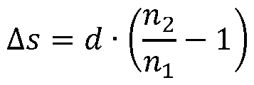 For applications in the field of 3D printing, the refractive index of the starting material 3 can be similar to the material of the receptacle 1. In this case, only the transition leads to air with a refractive index and receiving vessel 1 with refractive index n 2 to a shift of the focal plane by the amount Äs given by:
Mit zunehmendem Abstand d der Position des Lichtschnitts (Licht erster Wellenlänge) von einem Eintrittsfenster des Aufnahmegefäßes 1, wo das Projektorbild eintritt, nimmt die Fo kusverschiebung gemäß der obigen Gleichung zu. Die Gleichung betrifft einen paraxialen, optischen Strahlengang beziehungsweise größere Abstände zwischen Projektor 7 und Auf nahmegefäß 1. Je nach Ausgestaltung, kann eine Kompensation der Verschiebung mittels einer motorisierten Fokusverstellung des fest montierten Projektors 7 oder mittels einer mo torisierten Positionierung des gesamten Projektors 7 relativ zur Lichtschnittposition erfolgen. Im letztgenannten Beispiel ergibt sich eine gleichförmige, lineare Relativbewegung des Pro jektors 7 zum festen Lichtschnitt während der gleichförmigen Bewegung des Aufnahmegefä ßes 1 durch den Lichtschnitt (Schichtteilvolumen) zur Prozessierung des gesamten Arbeits volumens 2. With increasing distance d of the position of the light section (light of the first wavelength) from an entry window of the receiving vessel 1, where the projector image enters, the focus shift increases according to the above equation. The equation relates to a paraxial, optical beam path or larger distances between the projector 7 and receiving vessel 1. Depending on the configuration, the displacement can be compensated by means of a motorized focus adjustment of the fixed projector 7 or by means of a motorized positioning of the entire projector 7 relative to the light section position respectively. In the last-mentioned example, there is a uniform, linear relative movement of the projector 7 to the fixed light section during the uniform movement of the receptacle 1 through the light section (partial layer volume) for processing the entire working volume 2.
Alternativ zu dem in Fig. 1 veranschaulichten Aufbau, kann das Projektorbild auch durch den Boden oder den Deckel des Aufnahmegefäßes 1 in das Arbeitsvolumen 2 eintreten, und der Lichtschnitt kann senkrecht hierzu durch eine oder mehrere der Seitenfenster eingekoppelt werden. As an alternative to the structure illustrated in FIG. 1, the projector image can also enter the working volume 2 through the base or cover of the receptacle 1, and the light section can be coupled in perpendicular thereto through one or more of the side windows.
Alternativ kann der Lichtschnittgenerator 5 die Wellenlänge Ä2 erzeugen, und der Projektor 7 erzeugt die Wellenlänge
 Sofern der Übergang vom Zwischenzustand B in den Ausgangszustand A mit Licht der Wel lenlänge Ä3 erfolgen soll, erzeugt der Projektor 7 die Wellenlängen L ^ und A3 oder die Wellen längen Ä2 und A3, jeweils komplementär zur Wellenlänge des Lichtschnittgenerators. Alternatively, the light section generator 5 can generate the wavelength λ 2 , and the projector 7 generates the wavelength If the transition from the intermediate state B to the initial state A with light of Wel len length Ä 3 , the projector 7 generates the wavelengths L ^ and A 3 or the wavelengths Ä 2 and A 3 , each complementary to the wavelength of the light section generator.
Das Aufnahmegefäß 1 kann auch als Durchfluss-System mit automatisierter Zu- und Abfüh rung des Ausgangsmaterials 3 realisiert werden, um ausgedehnte Volumina zu prozessieren. The receptacle 1 can also be implemented as a flow-through system with automated supply and removal of the starting material 3 in order to process extensive volumes.
Ein oder mehrere Lichtdetektoren 8a, 8b (Kamera oder einfacher Fotodetektor; vgl. Fig. 1 und 2) können benutzt werden, um die Vorgänge bei der Prozessierung zu untersuchen, indem das transmittierte Licht der Anregung des Lichtschnitts und gegebenenfalls des Pro jektors 7 gemessen wird. Hierbei können der Lichtschnittgenerator 5 und gegebenenfalls auch der Projektor 7 weitere Lichtwellenlängen emittieren, die von den Anregungswellenlän gen verschieden sind und nur der Beobachtung der Änderung der Materialeigenschaft des Ausgangsmaterials 3 dienen, zum Beispiel der Polymerisation. One or more light detectors 8a, 8b (camera or simple photodetector; see. Fig. 1 and 2) can be used to examine the processes during processing by measuring the transmitted light of the excitation of the light section and possibly the projector 7 . Here, the light section generator 5 and possibly also the projector 7 can emit further light wavelengths that are different from the excitation wavelengths and only serve to observe the change in the material properties of the starting material 3, for example the polymerization.
Weiterhin kann eine Messung der emittierten Fluoreszenz von im Ausgangsmaterial 3 be findlichen, angeregten Fotoinitiatoren vorgesehen sein. Es können zum Beispiel die Intensi tät des gesamten transmittierten oder emittierten Lichts über einen Einzelphotodetektor ge messen und / oder die ortsaufgelöste Intensität über eine Kamera aufgezeichnet werden. Die Detektoren können über Vorgesetzte Filter oder Spektrographen selektiv nur bestimmte Lichtwellenlängen des Projektors 7, des Lichtschnittgenerators 5 oder der Licht emittieren den, angeregten Fotoinitiatoren messen. Furthermore, a measurement of the emitted fluorescence of the excited photoinitiators in the starting material 3 can be provided. For example, the intensity of the entire transmitted or emitted light can be measured using an individual photodetector and / or the spatially resolved intensity can be recorded using a camera. The detectors can selectively measure only certain light wavelengths of the projector 7, the light section generator 5 or the light emitting the excited photo initiators via upstream filters or spectrographs.
Die Auswertung der gesamten oder ortsaufgelösten Intensitäten kann eine Regelschleife steuern, welche die Intensität des Lichtschnittgenerators, die Intensität und Bildausgabe des Projektors, die Zeitsteuerung der Belichtungssequenz sowie die Verschiebung des Licht schnitts innerhalb des Aufnahmegefäßes 1 beeinflusst. Hierfür ist eine Steuereinrichtung 9 vorgesehen, die gemäß Fig. 1 an die Lichtquelle 5 und den Projektor 7 koppelt. The evaluation of the entire or spatially resolved intensities can control a control loop which influences the intensity of the light section generator, the intensity and image output of the projector, the timing of the exposure sequence and the displacement of the light section within the receptacle 1. For this purpose, a control device 9 is provided which, as shown in FIG. 1, couples to the light source 5 and the projector 7.
Als Lichtquelle 5 kann eine Laserlichtquelle genutzt werden, zum Beispiel ein pulsbarer Sin- gle-Mode-Diodenlaser (Fabrikat: IBEAM SMART, Toptica Photonics AG, DE) mit einer Wel lenlänge von 375nm und einer Ausgangsleistung im Dauerstrichbetrieb von max. 70mW, der Laserstrahldurchmesser beträgt 1.3mm (@ 1/e2). Eine asphärische POWELL Linse (Auffä cherungswinkel 30°, N-BK7, Edmund Optics GmbH, DE) dient zur Umformung des Laser strahls in eine divergierende Laserlinie. Eine direkt dahinter angeordnete plankonvexe Zylin-
derlinse mit langer Brennweite (f = 300.00 mm, N-BK7, Thorlabs GmbH, DE) und senkrech ter Orientierung zur Auffächerungsebene generiert in einem Ausführungsbeispiel eine Strahl taille mit einem Durchmesser von etwa d=100pm an der Position des Gefäßes mit dem Aus gangsmaterial im Abstand von 30cm von dieser Linse. Eine plankonvexe Zylinderlinse (f = 150.00 mm, N-BK7, Thorlabs GmbH, DE) im Abstand der einfachen Brennweite zur POWELL Linse kollimiert die divergierende Laserlinie und sorgt für einen annährend paralle len Strahlenverlauf entlang der optischen Achse, die Höhe des Lichtschnitts nach der Kolli- mierung beträgt ca. 8.5cm. Vor dem Gefäß ist eine weitere Zylinderlinse der Brennweite (f = 100.00 mm, N-BK7) flexibel positioniert, welche den Strahlenverlauf in einen zulaufenden Lichtschnitt überführt, welche den Intensitätsabfall durch das Lambert-Beersche Absorpti onsgesetz innerhalb des Gefäßes vermindert. Die nutzbare Höhe des Lichtschnitts im Be reich des Gefäßes durch die Fokussierung liegt bei etwa 2cm. A laser light source can be used as light source 5, for example a pulsable single-mode diode laser (make: IBEAM SMART, Toptica Photonics AG, DE) with a wavelength of 375 nm and an output power in continuous wave operation of max. 70 mW, the laser beam diameter is 1.3mm (@ 1 / e 2 ). An aspherical POWELL lens (fan angle 30 °, N-BK7, Edmund Optics GmbH, DE) is used to transform the laser beam into a diverging laser line. A plano-convex cylinder arranged directly behind The lens with a long focal length (f = 300.00 mm, N-BK7, Thorlabs GmbH, DE) and perpendicular orientation to the fanning plane generates, in one embodiment, a beam waist with a diameter of approximately d = 100 pm at the position of the vessel with the starting material in the Distance of 30cm from this lens. A plano-convex cylinder lens (f = 150.00 mm, N-BK7, Thorlabs GmbH, DE) at a distance of the single focal length to the POWELL lens collimates the diverging laser line and ensures an approximately parallel beam path along the optical axis, the height of the light section after the package - mation is approx. 8.5cm. Another cylindrical lens of focal length (f = 100.00 mm, N-BK7) is flexibly positioned in front of the vessel, which converts the beam path into a converging light section, which reduces the drop in intensity due to the Lambert-Beer law of absorption within the vessel. The usable height of the light section in the area of the vessel due to the focusing is around 2 cm.
Für eine Umformung eines Laserstrahls in eine divergierende Laserlinie kann alternativ zur POWELL Linse auch ein geeignet angeordneter rotierender Polygonspiegel oder ein Gal- voscanner verwendet werden. Prinzipiell ist es auch möglich, anstelle des Lasers eine Licht quelle zu verwenden, die auf einer LED (Lichtemittierende Diode) oder einer thermischen Lichtquelle basiert. As an alternative to the POWELL lens, a suitably arranged rotating polygon mirror or a galvo scanner can also be used to transform a laser beam into a diverging laser line. In principle, it is also possible to use a light source instead of the laser that is based on an LED (light-emitting diode) or a thermal light source.
Als Bildprojektor oder Projektor 7 kann ein DMD (Digital Micromirror Device der Firma Texas Instruments) basierender Projektor (Fabrikat: ACER X138WH, Acer Group, Taiwan) mit einer Auflösung von 1280 x 720 Pixeln und 3300 Ansi Lumen verwendet werden. Die Projekti onsoptik wurde ersetzt durch ein Projektionsobjektiv mit 90mm Brennweite (Braun Ultralit 2,4 / 90, Braun Photo Technik GmbH, Deutschland), welches ein scharfes Abbild innerhalb des Gefäßes generiert. Zur Wellenlängenselektion dient ein vorgesetztes Filterglas (GG475, Schott AG, Deutschland). Die Ansteuerung des Projektors 7 erfolgt über ein HDMI-Interface. A DMD (digital micromirror device from Texas Instruments) based projector (make: ACER X138WH, Acer Group, Taiwan) with a resolution of 1280 x 720 pixels and 3300 Ansi lumens can be used as the image projector or projector 7. The projection optics were replaced by a projection lens with a 90mm focal length (Braun Ultralit 2.4 / 90, Braun Photo Technik GmbH, Germany), which generates a sharp image within the vessel. A filter glass (GG475, Schott AG, Germany) placed in front is used for wavelength selection. The projector 7 is controlled via an HDMI interface.
Als Aufnahmegefäß 1 kann zum Beispiel eine Großküvette aus optischem Glas (Innenmaße: 30mm x 30mm x 30mm, Hellma GmbH & Co. KG, DE) mit transparenten, planen Eintritts fenstern verwendet werden. For example, a large cuvette made of optical glass (internal dimensions: 30mm x 30mm x 30mm, Hellma GmbH & Co. KG, DE) with transparent, flat entry windows can be used as the receiving vessel 1.
In den Fig. 3a bis 3c zeigen schematische Darstellungen für eine Anordnung mit Aufnahme gefäß 1, in welchem das Arbeitsvolumen 2 mit dem hierin aufgenommenen Ausgangsmate rial 3 zum optischen Bearbeiten angeordnet ist. Es ist eine Anordnung von Lichtquellen 30 vorgesehen. Die Lichtquellen 30 (Lichtgeneratoren für Erzeugung des Lichtschnitts 31), die
dem Einstrahlen des Lichts erster Wellenlänge (Lichtschnitt) dienen, sind benachbart zum Aufnahmegefäß 1 angeordnet, insbesondere auf gegenüberliegenden Seiten. Bei der Aus gestaltung nach Fig. 3c ist die Anordnung von Lichtquellen 30 um das Aufnahmegefäß 1 mit dem Arbeitsvolumen 2 drehbar angeordnet, was mittels Pfeilen 32 schematisch gezeigt ist. 3a to 3c show schematic representations for an arrangement with receiving vessel 1, in which the working volume 2 with the starting material 3 received therein is arranged for optical processing. An arrangement of light sources 30 is provided. The light sources 30 (light generators for generating the light section 31), the which serve to irradiate the light of the first wavelength (light section) are arranged adjacent to the receiving vessel 1, in particular on opposite sides. In the embodiment according to FIG. 3c, the arrangement of light sources 30 is rotatably arranged around the receiving vessel 1 with the working volume 2, which is shown schematically by means of arrows 32.
Zwei oder mehrere der Lichtquellen 30 können benutzt werden, die von unterschiedlichen Seiten des Aufnahmegefäßes 1 in das Arbeitsvolumen 2 einstrahlen und mittels Überlage rung von Teilstrahlen den Lichtschnitt 31 generieren, also das jeweilige Schichtteilvolumen bestrahlen, in welche dann die Projektion 33 hinein erfolgt.. Two or more of the light sources 30 can be used, which radiate into the working volume 2 from different sides of the receptacle 1 and generate the light section 31 by superimposing partial beams, that is to say irradiate the respective partial slice volume into which the projection 33 then takes place.
Der Lichtschnitt 31 für das jeweils gerade bestrahlte Schichtteilvolumen ergibt sich durch die Aufsummierung der Einzeleinstrahlungen von den Lichtquellen 30 unter verschiedenen Ein strahlwinkeln. Um eine homogene Intensitätsverteilung des Lichtschnitts 31 mittels Überlage rung des Lichts von zwei oder mehrere Lichtquellen zu erzielen, können die Einzeleinstrah lungen anstelle einer homogenen Intensitätsverteilung eine gaußförmige oder eine ange passte inhomogene Intensitätsverteilung aufweisen. The light section 31 for the currently irradiated partial volume of the layer results from the summation of the individual irradiations from the light sources 30 at different beam angles. In order to achieve a homogeneous intensity distribution of the light section 31 by superimposing the light from two or more light sources, the individual injections can have a Gaussian or an adapted inhomogeneous intensity distribution instead of a homogeneous intensity distribution.
Bei einer weiteren Ausgestaltung nach Fig. 4 werden zwei oder mehrere Lichtschnitte 40 (Schichtteilvolumen) generiert, die unter einem Winkel in das Aufnahmegefäß 1 einfallen. Ein oder mehrere Projektionen 41 von Projektoren (zur Vereinfachung nicht gezeigt in Fig. 4) erzeugen in einer schrägen Fokusebene scharfe Abbildungen innerhalb der einzelnen Licht schnitte 40. Hierdurch kann eine Prozessierung mehrerer Schichtteilvolumen gleichzeitig erfolgen. In a further embodiment according to FIG. 4, two or more light slices 40 (partial slice volume) are generated which fall into the receiving vessel 1 at an angle. One or more projections 41 from projectors (not shown in FIG. 4 for the sake of simplicity) produce sharp images within the individual light sections 40 in an inclined focal plane. This allows processing of several partial layer volumes at the same time.
Bei den Ausgestaltungen nach den Fig. 3a bis 3c, 4 kann das Aufnahmegefäß 1 durch den Lichtschnitt 31, 40 bewegt werden, oder der Lichtschnitt 31, 40 bei fester Position des Auf nahmegefäßes 1 verschoben werden, um das Arbeitsvolumen 2 kontinuierlich und schließ lich vollständig zu prozessieren, indem dessen Schichtteilvolumen nacheinander optisch bearbeitet werden. In the embodiments according to FIGS. 3a to 3c, 4, the receiving vessel 1 can be moved through the light section 31, 40, or the light section 31, 40 can be moved with the fixed position of the receiving vessel 1 to the working volume 2 continuously and finally Lich completely to process by optically processing the partial volume of the layers one after the other.
Fig.5 zeigt schematische Darstellungen für eine weitere Anordnung mit Aufnahmegefäß 1. Sowohl ein Lichtschnitt 50 der ersten Wellenlänge als auch ein Projektorbild 51 der zweiten Wellenlänge werden mittels eines Projektionsgeräts 52 erzeugt und dann auf das Aufnah megefäß 1 eingestrahlt. Eine Anordnung von Lichtreflexionselementen 53, insbesondere Spiegeln, sorgt für die Abspaltung des Lichtschnitts 50 aus einer Strahlachse des Projekti-
onsgerätes 52 und die Einstrahlung des Lichtschnitts 50 quer zum Projektionsbild 51 in das Aufnahmegefäß 1. 5 shows schematic representations for a further arrangement with receiving vessel 1. Both a light section 50 of the first wavelength and a projector image 51 of the second wavelength are generated by means of a projection device 52 and then radiated onto the receiving vessel 1. An arrangement of light reflection elements 53, in particular mirrors, ensures that the light section 50 is split off from a beam axis of the projection onsgerätes 52 and the irradiation of the light section 50 transversely to the projection image 51 in the receiving vessel 1.
In einer Ausführungsform kann das Aufnahmegefäß 1 bewegt werden, um den Lichtstrahl durch das Arbeitsvolumen 2 zu bewegen. Das Projektorbild 51 wird mittels einer variablen Fokusoptik innerhalb des Lichtschnitts 50 scharf abgebildet. In einer weiteren Ausgestaltung bleibt das Aufnahmegefäß 1 unbewegt, und der Lichtschnitt 50 wird bewegt, indem ein Dis playelement des Projektionsgerätes 52, zum Beispiel eine LCD- oder ein DMD-Display, auf geteilt wird in einen zentralen Bereich 54, der das Projektorbild 51 erzeugt, und in zwei seit lich davon gelagerte Bereiche 55, die den Lichtschnitt 50 erzeugen. Hierzu werden Pixel des Displayelements mittels Steuerung der optischen Transmission oder Reflexion des Display elements so angesteuert, um eine seitliche Verschiebung des Lichtschnitts 50 zu realisieren. Hierbei werden ein zentraler Bereich des Displayelements mit der ersten Wellenlänge und äußeren Bereiche des Displayelements mit der zweiten Wellenlänge bestrahlt. In one embodiment, the receiving vessel 1 can be moved in order to move the light beam through the working volume 2. The projector image 51 is imaged sharply within the light section 50 by means of variable focus optics. In a further embodiment, the receptacle 1 remains stationary and the light section 50 is moved by dividing a display element of the projection device 52, for example an LCD or a DMD display, into a central area 54 that generates the projector image 51 , and in two areas 55 mounted laterally thereof, which generate the light section 50. For this purpose, pixels of the display element are controlled by controlling the optical transmission or reflection of the display element in such a way as to realize a lateral displacement of the light section 50. Here, a central area of the display element is irradiated with the first wavelength and outer areas of the display element with the second wavelength.
Fig. 6 zeigt eine schematische Darstellung einer weiteren Anordnung zum optischen Bear beiten des Ausgangsmaterials 3 im Aufnahmegefäß 1. Fig. 7 zeigt eine schematische Teil darstellung der Anordnung aus Fig. 6. FIG. 6 shows a schematic illustration of a further arrangement for optically processing the starting material 3 in the receiving vessel 1. FIG. 7 shows a schematic partial illustration of the arrangement from FIG. 6.
Ein Lichtschnitt 60 wird in einer horizontalen Ebene 61 mittels eines Laserstrahls 62 gene riert, der von oben in ein für den Laserstrahl 62 optisch transparentes Tauchrohr 63 eintritt und mittels eines motorgetriebenen, rotierenden Spiegels 64 in das Aufnahmegefäß 1 mit dem Ausgangsmaterial 3 umgelenkt wird. Mittels Rotation entsteht der Lichtschnitt 60 der ersten Wellenlänge. Durch einen Boden 65 des Aufnahmegefäßes 1 wird Projektorlicht 66 zweiter Wellenlänge eingestrahlt, um ein Projektorbild 67 in die horizontalen Ebene 61 des Lichtschnitts 60 scharf abzubilden. A light section 60 is generated in a horizontal plane 61 by means of a laser beam 62, which enters a dip tube 63 that is optically transparent for the laser beam 62 from above and is deflected into the receptacle 1 with the starting material 3 by means of a motor-driven, rotating mirror 64. The light section 60 of the first wavelength is created by means of rotation. Projector light 66 of the second wavelength is radiated through a base 65 of the receptacle 1 in order to sharply image a projector image 67 in the horizontal plane 61 of the light section 60.
Das Tauchrohr 63 ist nach unten geschlossen. Der motorgetriebene, rotierende Spiegel 64 sowie der Laserstrahlweg 62 sind vom Ausgangsmaterial 3 im Aufnahmegefäß 1 getrennt. Für die Prozessierung des Ausgangsmaterials 3 wird das Tauchrohr 63 hoch oder runter bewegt, wodurch die horizontale Ebene des Lichtschnitts 60 nach oben oder nach unten verschoben wird. The dip tube 63 is closed at the bottom. The motor-driven, rotating mirror 64 and the laser beam path 62 are separated from the starting material 3 in the receptacle 1. For the processing of the starting material 3, the immersion tube 63 is moved up or down, as a result of which the horizontal plane of the light section 60 is shifted up or down.
Nachfolgend werden weitere Aspekte des Verfahrens zum optischen Bearbeiten des Aus gangsmaterials 3 erläutert.
Die lokale Polymerisation des Ausgangsmaterials 3, vermittelt über die Lichtanregung der Fotoinitiatoren, erfolgt durch ein sequentielles Verfahren, bei dem eine Prozessierung Schicht für Schicht im freien Volumen innerhalb des Aufnahmegefäßes 1 erfolgt. Zunächst ist hierfür eine Zerlegung des gewünschten, dreidimensionalen Objektes in einzelne Schichtbil der mit definiertem Rasterabstand vorgesehen (Slicing). Mittels Überlagerung des Licht schnitts von der Lichtquelle 5 und des jeweiligen Schnittbildes des Projektors 7 erfolgt die Anregung der Dual-Color-Fotoinitiatoren vom Grundzustand A in die aktive Form C, welche die lokale Polymerisation des Ausgangsmaterials 3 initiiert. Nach Ablauf der Belichtungsse quenz für die aktuelle Schicht (Schichtteilvolumen) wird durch Bewegung des Aufnahmege fäßes 1 und / oder des Lichtschnitts und des Projektors 7 gemeinsam die Lichtanregung de finiert verschoben und die Belichtung einer benachbarten oder beliebigen anderen Schicht (anderes Schichtteilvolumen) vorgenommen. Die Translation der Projektionsanordnung oder des Aufnahmegefäßes 1 , die zum Beispiel mittels geeigneter Schrittmotoren realisiert wer den kann, kann gegebenenfalls unterhalb des Taillen-Durchmessers des Lichtschnitts liegen, um eine Erhöhung der Auflösung in Bewegungsrichtung zu erzeugen. Further aspects of the method for optically processing the starting material 3 are explained below. The local polymerization of the starting material 3, mediated by the light excitation of the photoinitiators, takes place by a sequential process in which processing takes place layer by layer in the free volume within the receptacle 1. First of all, the desired three-dimensional object is broken down into individual slice images with a defined grid spacing (slicing). By superimposing the light section from the light source 5 and the respective sectional image of the projector 7, the dual-color photoinitiators are excited from the basic state A to the active form C, which initiates the local polymerization of the starting material 3. After the exposure sequence for the current slice (slice partial volume), the light excitation is shifted in a defined manner by moving the receptacle 1 and / or the light section and the projector 7 and the exposure of an adjacent or any other slice (different slice partial volume) is carried out. The translation of the projection arrangement or of the receptacle 1, which can be implemented for example by means of suitable stepper motors, can optionally be below the waist diameter of the light section in order to generate an increase in resolution in the direction of movement.
Für den zeitlichen Ablauf einer Belichtungssequenz für jedes Schichtteilvolumen gibt es ver schiedene Optionen, die je nach Ausgangsmaterial und den Eigenschaften der verwendeten Dual-Color-Fotoinitiatoren zur Anwendung kommen: There are various options for the timing of an exposure sequence for each partial volume of the layer, which are used depending on the starting material and the properties of the dual-color photoinitiators used:
Variante (1): Gleichzeitiges Einschalten beider Lichtquellen (L^ Ä2 und gegebenenfalls Ä3) mit definierten, gegebenenfalls unterschiedlichen Intensitäten für eine vorgegebene Belichtungs zeitspanne. Nach dem gleichzeitigen Abschalten beginnt die Translation des Systems zur nächsten Schicht. Variant (1): Simultaneous switching on of both light sources (L ^ Ä 2 and possibly Ä 3 ) with defined, possibly different intensities for a given exposure period. After switching off at the same time, the system begins to translate to the next layer.
Variante (2): Die erste Lichtquelle 5 (Lichtschnittgenerator) und der Projektor 7 werden zeit lich gepulst betrieben. Die Anzahl, Dauer und Intensität der Impulse sowie der Zeitversatz zwischen den Startflanken beider Impulse können im Rahmen einer definierten Belichtungs zeit pro Schichtteilvolumen frei eingestellt werden. Bei der Verwendung mehrerer Impulse innerhalb der Prozessierung eines Schichtteilvolumens können jedem Impuls ein unter schiedliches Bild des Projektors 7 zugeordnet werden. Nach der Belichtungszeit erfolgt die Translation zum nächsten Schichtteilvolumen. Variant (2): The first light source 5 (light section generator) and the projector 7 are operated in a pulsed manner. The number, duration and intensity of the pulses as well as the time offset between the starting edges of the two pulses can be freely set within a defined exposure time per slice partial volume. When using several pulses within the processing of a partial volume of the slice, a different image of the projector 7 can be assigned to each pulse. After the exposure time, the translation to the next partial slice volume takes place.
Variante (3): Die erste Lichtquelle 5 (Lichtschnittgenerator) bleibt immer eingeschaltet, wäh rend das Projektorbild nach einer definierten Belichtungszeit mit der Translation der Anord nung zur nächsten Schicht, umgeschaltet wird. Variant (3): The first light source 5 (light section generator) always remains switched on, while the projector image is switched over after a defined exposure time with the translation of the arrangement to the next layer.
Variante (4): Physikalisch mögliche Kombinationen der Varianten (1), (2) und (3).
Das hier vorgestellte volumetrische Verfahren generiert das gewünschte räumliche Objekt durch Polymerisation des Ausgangsmaterials 3 innerhalb des Arbeitsvolumens 2 schichtwei se, jedoch lässt es den grundlegenden Aufbau des Ausgangsmaterials 3 unverändert. Dies ist ein Vorteil gegenüber Verfahren, die das Ausgangsmaterial nur in voneinander getrennten Schichten prozessieren können. Durch die schichtweise Belichtung ist das Verfahren prinzi piell schneller als die Polymerisation des Ausgangsmaterials Punkt für Punkt. Variant (4): Physically possible combinations of variants (1), (2) and (3). The volumetric method presented here generates the desired spatial object by polymerizing the starting material 3 within the working volume 2 layer by layer, but it leaves the basic structure of the starting material 3 unchanged. This is an advantage compared to methods that can only process the starting material in separate layers. Due to the layer-by-layer exposure, the process is in principle faster than the polymerization of the starting material point by point.
Aufgrund der Aufweitung des Lichtschnittes lässt sich ein größerer Bereich des Arbeitsvolu mens 2 gleichzeitig und damit schneller prozessieren, was jedoch einen Verlust an Auflö sung bedingt. Due to the widening of the light section, a larger area of the working volume 2 can be processed simultaneously and thus more quickly, which, however, causes a loss of resolution.
Die Erzeugung des Lichtschnittes mittels der Lichtquelle 5 bedingt eine Kopplung zwischen dem minimalen Taillendurchmesser und der Divergenz des Strahlbündels, die zu einer Auf weitung des Lichtstrahls zum Rand des Volumens führt. Dadurch lässt sich entweder eine homogene, mittlere Auflösung entlang des Lichtschnittes erzeugen oder eine höhere Auflö sung im Bereich der Taille mit stärkerem Abfall zu den Rändern generieren. The generation of the light section by means of the light source 5 requires a coupling between the minimum waist diameter and the divergence of the beam, which leads to an expansion of the light beam to the edge of the volume. This means that either a homogeneous, medium resolution can be generated along the light section or a higher resolution can be generated in the area of the waist with a greater drop towards the edges.
Da im zeitlichen Ablauf eine frühere Prozessierung von Schichten ermöglicht ist, die zum Projektor 7 weiter entfernt liegen, wird eine mögliche Beeinflussung der Lichtpropagation des Projektorbildes (Licht zweiter Wellenlänge) durch schon ausgehärtete Schichten vermieden. Since layers which are further away from the projector 7 can be processed earlier in the course of time, possible influencing of the light propagation of the projector image (light of the second wavelength) by layers that have already cured is avoided.
Aufgrund der Verschiebung des Lichtschnitts wird jedes Schichtteilvolumen nur einmal pro zessiert und erhält damit eine definierte Energiedosis. Dadurch wird die Polymerisierung von ungewünschten Gebieten, bei der Verwendung von nicht-idealen Dual Color Fotoinitiaoren, effektiv vermindert. Due to the shift in the light section, each partial volume of the layer is processed only once and thus receives a defined absorbed dose. This effectively reduces the polymerization of undesired areas when using non-ideal dual color photo initiators.
Ist die Kinetik der durch die Lichteinstrahlung ausgelösten Reaktionen der Fotoinitiator- Moleküle und des Ausgangsmaterials 3 hinreichend bekannt, erlaubt die gezielte Zeitsteue rung der Lichtimpulse zueinander und geeignete Wahl der Intensitäten beider Wellenlängen eine höhere Diskriminierung zwischen gewünschter und ungewünschter Polymerisation im Arbeitsvolumen 2. Hierdurch lassen sich Artefakte und eine Degradation der Auflösung für nicht-ideale Dual-Color-Fotoinitiatoren vermindern.
Die in der vorstehenden Beschreibung, den Ansprüchen sowie der Zeichnung offenbarten Merkmale können sowohl einzeln als auch in beliebiger Kombination für die Verwirklichung der verschiedenen Ausführungen von Bedeutung sein.
If the kinetics of the reactions of the photoinitiator molecules and the starting material 3 triggered by the light irradiation are sufficiently known, the targeted timing of the light pulses to one another and a suitable choice of the intensities of both wavelengths allows a greater discrimination between desired and undesired polymerization in the working volume 2 Reduce artifacts and resolution degradation for non-ideal dual color photo initiators. The features disclosed in the above description, the claims and the drawing can be of importance both individually and in any combination for the implementation of the various designs.
Claims
1. Verfahren zum Bearbeiten eines optisch reaktiven Materials, mit: 1. A method of processing an optically reactive material, comprising:
- Bereitstellen eines Ausgangsmaterial (3), welches optisch reaktiv ist und ein Ar beitsvolumen (2) ausfüllt; und - Provision of a starting material (3) which is optically reactive and fills a work volume (2); and
- optisches Bearbeiten des Ausgangsmaterials (3) in dem Arbeitsvolumen (2) mittels Einstrahlen von Licht einer ersten Wellenlänge und Licht einer zweiten Wellenlänge, die von der ersten Wellenlänge verschieden ist, wobei das Licht erster Wellenlänge und das Licht zweiter Wellenlänge von einer Beleuchtungseinrichtung bereitgestellt werden und mittels des optischen Bearbeitens wenigstens eine Materialeigenschaft des Ausgangsmaterials verändert wird und das optische Bearbeiten Folgendes um fasst: - Optical processing of the starting material (3) in the working volume (2) by means of irradiation of light of a first wavelength and light of a second wavelength that is different from the first wavelength, the light of the first wavelength and the light of the second wavelength being provided by a lighting device and at least one material property of the starting material is changed by means of the optical processing and the optical processing comprises the following:
- Bestrahlen eines ersten Schichtteilvolumens des mit dem Ausgangsmaterial (3) ausgefüllten Arbeitsvolumens (2) mit dem Licht erster Wellenlänge; - Irradiating a first layer partial volume of the working volume (2) filled with the starting material (3) with the light of the first wavelength;
- Bestrahlen des ersten Schichtteilvolumens des Arbeitsvolumens (2) mit dem Licht zweiter Wellenlänge, wobei das Licht zweiter Wellenlänge hierbei mittels einer Projektionseinrichtung (7) nur das erste Schichtteilvolumen ganz oder teil weise erfassend in das Arbeitsvolumen (2) projiziert wird; - Irradiating the first slice partial volume of the working volume (2) with the light of the second wavelength, the light of the second wavelength being projected into the working volume (2) by means of a projection device (7) so as to capture only the first slice partial volume in whole or in part;
- Bestrahlen eines zweiten Schichtteilvolumens des mit dem Ausgangsmaterial (3) ausgefüllten Arbeitsvolumens (2), welches von dem ersten Schichtteilvolumen verschieden ist, mit dem Licht erster Wellenlänge; - Irradiating a second partial volume of the layer of the working volume (2) filled with the starting material (3), which is different from the first partial volume of the layer, with the light of the first wavelength;
- Bestrahlen des zweiten Schichtteilvolumens des Arbeitsvolumens (2) mit dem Licht zweiter Wellenlänge, wobei das Licht zweiter Wellenlänge hierbei mittels der Projektionseinrichtung (7) nur das zweite Schichtteilvolumen ganz oder teil weise erfassend in das Arbeitsvolumen (2) projiziert wird; und - Irradiating the second partial volume of the slice of the working volume (2) with the light of the second wavelength, the second wavelength light being projected into the working volume (2) by means of the projection device (7), capturing only the second partial volume of the slice in whole or in part; and
- Wiederholen der vorangehenden Schritte zur schichtweisen optischen Bearbei tung des Ausgangsmaterials (3) in dem Arbeitsvolumen (2) bis ein zu bearbei tendes Volumen des Ausgangsmaterials (3), welches das Arbeitsvolumen (2) ganz oder teilweise erfasst, optisch bearbeitet ist. - Repeating the preceding steps for layer-by-layer optical processing of the starting material (3) in the working volume (2) until a volume to be processed of the starting material (3), which covers the working volume (2) in whole or in part, is optically processed.
2. Verfahren nach Anspruch 1 , dadurch g e ke n n z e i c h n e t, dass mit Hilfe einer Steu ereinrichtung (9), die mit einer oder mehreren Lichtquellen (5) zum Bereitstellen des Lichts erster und des Lichts zweiter Wellenlänge sowie der Projektionseinrichtung (7) verbunden ist, bestimmt wird, ob das erste oder das zweite Schichtteilvolumen be strahlt werden, und die Projektionseinrichtung (7) in Abhängigkeit hiervon angesteuert
wird, das Licht zweiter Wellenlänge in das erste oder das zweite Schichtteilvolumen zu projizieren. 2. The method according to claim 1, characterized in that with the help of a control device (9) which is connected to one or more light sources (5) for providing the light of the first and the light of the second wavelength and the projection device (7), it is determined whether the first or the second slice partial volume be irradiated, and the projection device (7) is controlled as a function thereof is to project the light of the second wavelength into the first or the second partial volume of the layer.
3. Verfahren nach Anspruch 1 oder 2, dadurch gekennzeichnet, dass das Licht erster Wellenlänge und das Licht zweiter Wellenlänge zumindest für einen zeitlichen Überlappungszeitraum gleichzeitig gemeinsam in das erste oder das zweite Schicht teilvolumen eingestrahlt werden. 3. The method according to claim 1 or 2, characterized in that the light of the first wavelength and the light of the second wavelength are simultaneously radiated together into the first or the second layer partial volume at least for a temporal overlap period.
4. Verfahren nach mindestens einem der vorangehenden Ansprüche, dadurch g e - kennzeichnet, dass das erste und das zweite Schichtteilvolumen in dem Arbeits volumen (2) benachbarte Schichtteilvolumen des Ausgangsmaterials (3) bilden. 4. The method according to at least one of the preceding claims, characterized in that the first and the second partial layer volume in the working volume (2) form adjacent partial layer volumes of the starting material (3).
5. Verfahren nach Anspruch 4, dadurch gekennzeichnet, dass das erste und das zweite Schichtteilvolumen einer der folgenden Konfigurationen von Teilvolumen ent sprechend gebildet werden: randseitig überlappend, randseitig aneinanderstoßend und randseitig beabstandet zueinander. 5. The method according to claim 4, characterized in that the first and the second layer partial volume are formed accordingly to one of the following configurations of partial volumes: overlapping on the edge, abutting on the edge and spaced apart from one another on the edge.
6. Verfahren nach mindestens einem der vorangehenden Ansprüche, dadurch g e - kennzeichnet, dass auf das Ausgangsmaterial (3) im Arbeitsvolumen (2) das Licht erster Wellenlänge entlang einer ersten Einstrahlrichtung und das Licht zweiter Wellenlänge entlang einer zweiten Einstrahlrichtung eingestrahlt werden, die quer zur ersten Einstrahlrichtung verläuft. 6. The method according to at least one of the preceding claims, characterized in that on the starting material (3) in the working volume (2) the light of the first wavelength along a first direction of irradiation and the light of the second wavelength are irradiated along a second direction of irradiation, which is transverse to first irradiation direction.
7. Verfahren nach mindestens einem der vorangehenden Ansprüche, dadurch ge kennzeichnet, dass das Licht erster Wellenlänge und / oder das Licht zweiter Wellenlänge als gepulstes Licht eingestrahlt werden. 7. The method according to at least one of the preceding claims, characterized in that the light of the first wavelength and / or the light of the second wavelength are irradiated as pulsed light.
8. Verfahren nach mindestens einem der vorangehenden Ansprüche, dadurch g e - kennzeichnet, dass das Ausgangsmaterial (3) mittels des optischen Bearbeitens entsprechend wenigstens eines Bearbeitungsverfahrens aus der folgenden Gruppe bearbeitet wird: Aushärten, Härten, Gelieren und Verflüssigen. 8. The method according to at least one of the preceding claims, characterized in that the starting material (3) is processed by means of optical processing in accordance with at least one processing method from the following group: curing, hardening, gelling and liquefying.
9. Verfahren nach mindestens einem der vorangehenden Ansprüche, dadurch g e - kennzeichnet, dass zum Bestrahlen des ersten Schichtteilvolumens und zum Be strahlen des zweiten Schichtvolumens mit dem Licht erster Wellenlänge ein schicht-
förmiger Einstrahlbereich einer ersten Lichtquelle, mit der das Licht erster Wellenlänge bereitgestellt wird, relativ zum mit dem Ausgangsmaterial (3) ausgefüllten Arbeitsvolu men (2) verlagert wird. 9. The method according to at least one of the preceding claims, characterized in that for irradiating the first layer partial volume and for irradiating the second layer volume with the light of the first wavelength a layer Shaped irradiation area of a first light source, with which the light of the first wavelength is provided, is displaced relative to the working volume (2) filled with the starting material (3).
10. Verfahren nach mindestens einem der vorangehenden Ansprüche, dadurch ge kennzeichnet, dass das optische Bearbeiten des Ausgangsmaterials (3) mit Hilfe eines Lichtdetektors (8a; 8b) beobachtet wird. 10. The method according to at least one of the preceding claims, characterized in that the optical processing of the starting material (3) is observed with the aid of a light detector (8a; 8b).
11. Verfahren nach mindestens einem der vorangehenden Ansprüche, dadurch ge kennzeichnet, dass das mittels des optischen Bearbeitens in dem Ausgangsma terial (3) eine polychrome Mehrphotonen-Polymerisation ausgelöst wird, welche die Veränderung der wenigstens einen Materialeigenschaft des Ausgangsmaterials (3) bewirkt. 11. The method according to at least one of the preceding claims, characterized in that a polychrome multiphoton polymerization is triggered by means of the optical processing in the starting material (3), which causes the change in the at least one material property of the starting material (3).
12. Verfahren nach mindestens einem der vorangehenden Ansprüche, dadurch ge kennzeichnet, dass das Licht erster Wellenlänge zunächst in dem ersten Schich- teilvolumen und dann in dem zweiten Schichtteilvolumen mit einer in Bezug auf min destens einen der folgenden Lichtparameter im Wesentlichen homogenen Verteilung eingestrahlt wird: Lichtintensität und Lichtfarbe. 12. The method according to at least one of the preceding claims, characterized in that the light of the first wavelength is irradiated first in the first layer partial volume and then in the second layer partial volume with an essentially homogeneous distribution with respect to at least one of the following light parameters: Light intensity and light color.
13. Verfahren nach mindestens einem der vorangehenden Ansprüche, dadurch ge kennzeichnet, dass das Licht zweiter Wellenlänge zunächst auf das erste Schichteilvolumen und dann auf das zweite Schichtteilvolumen mit einer in Bezug auf mindestens einen der folgenden Lichtparameter nicht-homogenen Verteilung projiziert wird: Lichtintensität und Lichtfarbe. 13. The method according to at least one of the preceding claims, characterized in that the light of the second wavelength is initially projected onto the first partial layer volume and then onto the second partial layer volume with a non-homogeneous distribution with respect to at least one of the following light parameters: light intensity and light color .
14. Verfahren nach mindestens einem der vorangehenden Ansprüche, dadurch ge kennzeichnet, dass beim Bestrahlen des ersten Schichtteilvolumens und / oder beim Bestrahlen des zweiten Schichteilvolumens mit dem Licht erster Wellenlänge ein Schichteilvolumen mit einer Schichtdicke von höchstens etwa 1 mm bestrahlt wird. 14. The method according to at least one of the preceding claims, characterized in that when irradiating the first layer partial volume and / or when irradiating the second layer partial volume with the light of the first wavelength, a layer partial volume with a layer thickness of at most about 1 mm is irradiated.
15. Vorrichtung zum Bearbeiten eines optisch reaktiven Materials, mit: 15. Apparatus for processing an optically reactive material, comprising:
- einem Arbeitsvolumen (2), welches eingerichtet ist, ein Ausgangsmaterial (3) aufzu nehmen, welches optisch reaktiv ist und das Arbeitsvolumen (2) ausfüllt;
- einer Beleuchtungseinrichtung, die eingerichtet ist, Licht einer ersten Wellenlänge und Licht einer zweiten Wellenlänge zum Einstrahlen auf das Arbeitsvolumen (2) mit dem Ausgangsmaterial (3) bereitzustellen; und - A working volume (2) which is set up to take up a starting material (3) which is optically reactive and fills the working volume (2); - a lighting device which is set up to provide light of a first wavelength and light of a second wavelength for irradiating onto the working volume (2) with the starting material (3); and
- einer Projektionseinrichtung (7), die eingerichtet ist, das Licht zweiter Wellenlänge beim Einstrahlen auf das mit dem Ausgangsmaterial (3) ausgefüllten Arbeitsvolu men (2) in ein Schichtteilvolumen des Arbeitsvolumens (2) und nur das Schichtteil volumen ganz oder teilweise erfassend zu projizieren; wobei die Beleuchtungseinrichtung und die Projektionseinrichtung (7) weiterhin einge richtet sind, das Ausgangsmaterial (3) in dem Arbeitsvolumen (2) wie folgt optisch zu bearbeiten: - A projection device (7) which is set up to project the light of the second wavelength when it is irradiated onto the working volume (2) filled with the starting material (3) in a partial layer volume of the working volume (2) and only the partial volume of the layer is projected ; wherein the lighting device and the projection device (7) are also set up to optically process the starting material (3) in the working volume (2) as follows:
- Bestrahlen eines ersten Schichtteilvolumens des mit dem Ausgangsmaterial (3) ausgefüllten Arbeitsvolumens (2) mit dem Licht erster Wellenlänge; - Irradiating a first layer partial volume of the working volume (2) filled with the starting material (3) with the light of the first wavelength;
- Bestrahlen des ersten Schichtteilvolumens des Arbeitsvolumens (2) mit dem Licht zweiter Wellenlänge, wobei das Licht zweiter Wellenlänge hierbei mittels einer Pro jektionseinrichtung (7) nur das erste Schichtteilvolumen ganz oder teilweise erfas send in das Arbeitsvolumen (2) projiziert wird; - Irradiating the first slice partial volume of the working volume (2) with the light of the second wavelength, the light of the second wavelength being projected into the working volume (2) in whole or in part by means of a projection device (7);
- Bestrahlen eines zweiten Schichtteilvolumens des mit dem Ausgangsmaterial (3) ausgefüllten Arbeitsvolumens (2), welches von dem ersten Schichtteilvolumen ver schieden ist, mit dem Licht erster Wellenlänge; - Irradiating a second layer partial volume of the working volume (2) filled with the starting material (3), which is different from the first layer partial volume, with the light of the first wavelength;
- Bestrahlen des zweiten Schichtteilvolumens des Arbeitsvolumens (2) mit dem Licht zweiter Wellenlänge, wobei das Licht zweiter Wellenlänge hierbei mittels der Projek tionseinrichtung (7) nur das zweite Schichtteilvolumen ganz oder teilweise erfassend in das Arbeitsvolumen (2) projiziert wird; und - Irradiating the second partial volume of the slice of the working volume (2) with the light of the second wavelength, the second wavelength light being projected into the working volume (2) in full or in part by means of the projection device (7); and
- Wiederholen der vorangehenden Schritte zur schichtweisen optischen Bearbeitung des Ausgangsmaterials (3) in dem Arbeitsvolumen (2) bis ein zu bearbeitendes Vo lumen des Ausgangsmaterials (3), welches das Arbeitsvolumen (2) ganz oder teil weise erfasst, optisch bearbeitet ist.
- Repeating the previous steps for optical processing of the starting material (3) in layers in the working volume (2) until a volume of the starting material (3) to be processed, which covers the working volume (2) in whole or in part, is optically processed.
Priority Applications (3)
| Application Number | Priority Date | Filing Date | Title |
|---|---|---|---|
| EP20807657.0A EP4054827B1 (en) | 2019-11-06 | 2020-11-06 | Method and apparatus for processing an optically reactive material |
| EP24150751.6A EP4360853A1 (en) | 2019-11-06 | 2020-11-06 | Method and apparatus for processing an optically reactive material |
| US17/755,624 US20220410473A1 (en) | 2019-11-06 | 2020-11-06 | Method and Apparatus for Processing an Optically Reactive Material |
Applications Claiming Priority (2)
| Application Number | Priority Date | Filing Date | Title |
|---|---|---|---|
| DE102019129868.7A DE102019129868A1 (en) | 2019-11-06 | 2019-11-06 | Method and device for processing an optically reactive material |
| DE102019129868.7 | 2019-11-06 |
Publications (1)
| Publication Number | Publication Date |
|---|---|
| WO2021089090A1 true WO2021089090A1 (en) | 2021-05-14 |
Family
ID=73451979
Family Applications (1)
| Application Number | Title | Priority Date | Filing Date |
|---|---|---|---|
| PCT/DE2020/100952 WO2021089090A1 (en) | 2019-11-06 | 2020-11-06 | Method and apparatus for processing an optically reactive material |
Country Status (4)
| Country | Link |
|---|---|
| US (1) | US20220410473A1 (en) |
| EP (2) | EP4054827B1 (en) |
| DE (1) | DE102019129868A1 (en) |
| WO (1) | WO2021089090A1 (en) |
Families Citing this family (2)
| Publication number | Priority date | Publication date | Assignee | Title |
|---|---|---|---|---|
| WO2023031140A1 (en) | 2021-09-03 | 2023-03-09 | Readily3D Sa | Method for digital analytic correction of photoresponsive material reactivity in additive manufacturing |
| EP4257340A1 (en) * | 2022-04-08 | 2023-10-11 | Photosynthetic B.V. | Method and apparatus for high-resolution fast layer-by-layer 3d printing |
Citations (4)
| Publication number | Priority date | Publication date | Assignee | Title |
|---|---|---|---|---|
| US4041476A (en) | 1971-07-23 | 1977-08-09 | Wyn Kelly Swainson | Method, medium and apparatus for producing three-dimensional figure product |
| US20190016052A1 (en) | 2017-07-11 | 2019-01-17 | Daniel S. Clark | 5d part growing machine with volumetric display technology |
| US20190160539A1 (en) | 2017-11-30 | 2019-05-30 | Applied Materials, Inc. | Additive Manufacturing with Overlapping Light Beams |
| WO2019194798A1 (en) * | 2018-04-04 | 2019-10-10 | Ford Global Technologies, Llc | 3-d printing components using two-light sources to control location of solidification |
Family Cites Families (5)
| Publication number | Priority date | Publication date | Assignee | Title |
|---|---|---|---|---|
| US160539A (en) | 1875-03-09 | Improvement in dishes of pottery-ware | ||
| US8404173B2 (en) * | 2006-11-17 | 2013-03-26 | Poof Technologies, Llc | Polymer object optical fabrication process |
| GB201501382D0 (en) * | 2015-01-28 | 2015-03-11 | Structo Pte Ltd | Additive manufacturing device with release mechanism |
| US11305482B2 (en) * | 2016-07-15 | 2022-04-19 | Purdue Research Foundation | Continuous and scalable 3D nanoprinting |
| US10875247B2 (en) * | 2016-07-15 | 2020-12-29 | Lawrence Livermore National Securitv. LLC | Multi-beam resin curing system and method for whole-volume additive manufacturing |
-
2019
- 2019-11-06 DE DE102019129868.7A patent/DE102019129868A1/en active Pending
-
2020
- 2020-11-06 EP EP20807657.0A patent/EP4054827B1/en active Active
- 2020-11-06 EP EP24150751.6A patent/EP4360853A1/en active Pending
- 2020-11-06 WO PCT/DE2020/100952 patent/WO2021089090A1/en unknown
- 2020-11-06 US US17/755,624 patent/US20220410473A1/en active Pending
Patent Citations (4)
| Publication number | Priority date | Publication date | Assignee | Title |
|---|---|---|---|---|
| US4041476A (en) | 1971-07-23 | 1977-08-09 | Wyn Kelly Swainson | Method, medium and apparatus for producing three-dimensional figure product |
| US20190016052A1 (en) | 2017-07-11 | 2019-01-17 | Daniel S. Clark | 5d part growing machine with volumetric display technology |
| US20190160539A1 (en) | 2017-11-30 | 2019-05-30 | Applied Materials, Inc. | Additive Manufacturing with Overlapping Light Beams |
| WO2019194798A1 (en) * | 2018-04-04 | 2019-10-10 | Ford Global Technologies, Llc | 3-d printing components using two-light sources to control location of solidification |
Also Published As
| Publication number | Publication date |
|---|---|
| US20220410473A1 (en) | 2022-12-29 |
| EP4054827C0 (en) | 2024-01-10 |
| EP4054827B1 (en) | 2024-01-10 |
| DE102019129868A1 (en) | 2021-05-06 |
| EP4360853A1 (en) | 2024-05-01 |
| EP4054827A1 (en) | 2022-09-14 |
Similar Documents
| Publication | Publication Date | Title |
|---|---|---|
| EP4032688B1 (en) | Method and device for producing a three-dimensional object in an optically reactive starting material | |
| DE102011000835B4 (en) | Scanning microscope and method for light microscopic imaging of an object | |
| EP1790383B1 (en) | Method and device for machining of a workpiece | |
| EP3864454B1 (en) | Method and device for high-resolution fluorescence microscopy | |
| DE102014108633B4 (en) | Device and method for producing three-dimensional objects using rapid prototyping | |
| EP4054827A1 (en) | Method and apparatus for processing an optically reactive material | |
| WO2012019577A2 (en) | Method for producing a three-dimensional component | |
| WO2014095864A1 (en) | Method for producing a homogeneous light distribution | |
| AT518051B1 (en) | Device and method for increasing the adhesion of a component layer to a carrier object | |
| EP2641078A1 (en) | Increased depth-resolution microscopy | |
| WO2014147207A1 (en) | Method and optical arrangement for manipulating and imaging a microscopic sample | |
| DE3422143A1 (en) | WAFER INSPECTION DEVICE | |
| DE10300091A1 (en) | microtome | |
| WO2016142398A1 (en) | Method and apparatus for correcting an inhomogeneous intensity distribution of a radiation field generated by a radiation source | |
| DE10111422A1 (en) | Photosensitive molding production by irradiating a liquid material in a bath, to solidify the material, using a multi-photon absorption process | |
| WO2020126154A1 (en) | Parallelised 3d lithography using muti-beam, multi-colour light-induced polymerisation | |
| WO2017102700A1 (en) | Method and arrangements for reducing the boundary surface adhesion in photopolymerization | |
| DE102012214932B4 (en) | Test sample apparatus and test method for a sub-wavelength optical microscope | |
| DE10139384A1 (en) | X-ray unit has filtering mirrors for difference imaging using light broadband source | |
| DE102014215213A1 (en) | Stereolithography device with container assembly | |
| DE102021105888A1 (en) | Optical system for obtaining 3D spatial information | |
| WO2023117679A1 (en) | Illumination device for illuminating a scene, camera system, and method for illuminating a scene | |
| DE2260016C3 (en) | Ophthalmic laser system | |
| DE102016107041A1 (en) | Microscope and microscopy method | |
| DE2307140A1 (en) | IMAGE AMPLIFIER USING A LASER RADIATOR |
Legal Events
| Date | Code | Title | Description |
|---|---|---|---|
| 121 | Ep: the epo has been informed by wipo that ep was designated in this application |
Ref document number: 20807657 Country of ref document: EP Kind code of ref document: A1 |
|
| ENP | Entry into the national phase |
Ref document number: 2020807657 Country of ref document: EP Effective date: 20220607 |