WO2021088239A1 - 一种通过液体体积测量试件动态侧向应变的装置及方法 - Google Patents
一种通过液体体积测量试件动态侧向应变的装置及方法 Download PDFInfo
- Publication number
- WO2021088239A1 WO2021088239A1 PCT/CN2019/129987 CN2019129987W WO2021088239A1 WO 2021088239 A1 WO2021088239 A1 WO 2021088239A1 CN 2019129987 W CN2019129987 W CN 2019129987W WO 2021088239 A1 WO2021088239 A1 WO 2021088239A1
- Authority
- WO
- WIPO (PCT)
- Prior art keywords
- test piece
- liquid
- dynamic
- elevation
- lateral strain
- Prior art date
- Legal status (The legal status is an assumption and is not a legal conclusion. Google has not performed a legal analysis and makes no representation as to the accuracy of the status listed.)
- Ceased
Links
Classifications
-
- G—PHYSICS
- G01—MEASURING; TESTING
- G01N—INVESTIGATING OR ANALYSING MATERIALS BY DETERMINING THEIR CHEMICAL OR PHYSICAL PROPERTIES
- G01N3/00—Investigating strength properties of solid materials by application of mechanical stress
- G01N3/02—Details
- G01N3/06—Special adaptations of indicating or recording means
-
- G—PHYSICS
- G01—MEASURING; TESTING
- G01N—INVESTIGATING OR ANALYSING MATERIALS BY DETERMINING THEIR CHEMICAL OR PHYSICAL PROPERTIES
- G01N3/00—Investigating strength properties of solid materials by application of mechanical stress
- G01N3/30—Investigating strength properties of solid materials by application of mechanical stress by applying a single impulsive force, e.g. by falling weight
-
- G—PHYSICS
- G01—MEASURING; TESTING
- G01N—INVESTIGATING OR ANALYSING MATERIALS BY DETERMINING THEIR CHEMICAL OR PHYSICAL PROPERTIES
- G01N2203/00—Investigating strength properties of solid materials by application of mechanical stress
- G01N2203/0001—Type of application of the stress
- G01N2203/001—Impulsive
-
- G—PHYSICS
- G01—MEASURING; TESTING
- G01N—INVESTIGATING OR ANALYSING MATERIALS BY DETERMINING THEIR CHEMICAL OR PHYSICAL PROPERTIES
- G01N2203/00—Investigating strength properties of solid materials by application of mechanical stress
- G01N2203/02—Details not specific for a particular testing method
- G01N2203/06—Indicating or recording means; Sensing means
- G01N2203/0611—Hydraulic or pneumatic indicating, recording or sensing means
Definitions
- the invention relates to the technical field of testing the dynamic mechanical properties of brittle materials such as coal and rock by using an SHPB experimental system, and specifically relates to a device and a method for measuring the dynamic lateral strain of a test piece through a liquid volume.
- the method of sticking strain gauges on the side of the specimen is now used to obtain the lateral strain of the material.
- This method has certain limitations.
- First, the lateral strain of the specimen is often uneven when the specimen is impacted by a dynamic load.
- the method of pasting a strain gauge can only test the strain at a certain point on the side of the specimen. It is inaccurate to express the lateral strain of the whole specimen in this way.
- the surface of the strain gauge is relatively rough and curved, which makes it difficult to stick the strain gauges, and does not fit the surface of the specimen well. It is easy to cause the strain gauges to fall off under the action of dynamic load, which affects Completeness of experimental data. Fourth, the strain gauge is stuck on the surface of the test piece, which is difficult to reuse.
- the present invention proposes a device and method for measuring the dynamic lateral strain of the test piece by liquid volume.
- a device for measuring the dynamic lateral strain of a test piece by liquid volume including a conversion device for converting the dynamic lateral strain information of the test piece into liquid elevation dynamic change information, and is used for real-time acquisition of liquid elevation dynamic change information Device, and a fixing device used to fix the conversion device on the SHPB test bench and adjust the vertical height of the conversion device;
- the conversion device includes a cylinder body, a cover plate and a rubber holster.
- the cylinder body is in the shape of a hollow cylinder and is arranged horizontally. Both ends of the cylinder body are respectively screwed with the cover plate.
- the center of the cover plate is provided with a rod for incident or transmission.
- the round hole through which the rod passes is provided with a rubber gasket for sealing the internal space of the cylinder between the cylinder body and the cover plate; the test piece is cylindrical, and the rubber holster is sleeved on the outside of the test piece, and The test piece is tightly wrapped, and the test piece is placed in the center of the cylinder body.
- the two ends of the test piece conflict with the ends of the incident rod and the transmission rod, respectively; the bottom two sides of the cylinder are provided with liquid inlet and The first liquid outlet hole is provided with a second liquid outlet hole on the top of the cylinder body.
- the liquid inlet hole and the first liquid outlet hole are connected with the infusion pipeline.
- a measuring tube is arranged above the cylinder body, and the measuring tube is open at both ends.
- the transparent glass tube of the mouth is placed vertically, and the bottom of the measuring tube is connected to the second outlet hole;
- the acquisition device includes an elevation signal sensor and a high-speed dynamic signal acquisition instrument.
- the elevation signal sensor includes a sensor housing, the sensor housing is sleeved on the outside of the measuring tube, and a vertically distributed light source is arranged on one side of the sensor housing, and on the other side of the sensor housing. Vertically distributed photosensitive elements are arranged on the side; the elevation signal sensor is connected to the high-speed dynamic signal acquisition instrument through a wire, and the high-speed dynamic signal acquisition instrument is connected to the computer;
- the fixing device includes a base, a movable column and an arc-shaped pallet.
- the pedestal is fixed on the SHPB test bench, the bottom end of the movable column is connected with the base, the top end of the movable column is connected with the arc-shaped pallet, and the arc-shaped pallet is connected with the cylinder.
- the bottom of the movable column is connected, and the movable column is equipped with an adjusting bolt for adjusting the lift of the movable column.
- a communicating piece is provided at the second outlet hole, the communicating piece is in an inverted T-shaped structure, and a through communicating hole is vertically arranged inside the communicating piece, and the bottom of the communicating piece is connected to the top of the cylinder, and the communicating piece The upper part of the measuring tube is inserted into the measuring tube, and the connecting piece seals the opening of the bottom end of the measuring tube.
- the outer surface of the cover plate is arranged as a frosted surface.
- a tapered thread connection is adopted between the liquid inlet hole and the first liquid outlet hole and the infusion pipeline.
- the sensor housing is an opaque black housing.
- a method for measuring the dynamic lateral strain of a test piece by liquid volume, using the device as described above, includes the following steps:
- the first step is to process the test piece into a cylindrical shape, measure and record the radial radius and axial length of the test piece;
- the second step is to place the conversion device at the position where the test piece is clamped on the SHPB test bench, and adjust the cylinder of the conversion device to a suitable height through the movable post of the fixing device; place the test piece in the rubber holster, and place the test piece The rubber sheath is placed inside the cylinder, and the test piece is clamped by the incident rod and the transmission rod in the SHPB experimental device;
- the third step is to install the acquisition device, turn on the elevation signal sensor and high-speed dynamic signal acquisition instrument, open the liquid inlet and the second liquid outlet, close the first liquid outlet, and inject liquid into the cylinder from the liquid inlet until The elevation signal sensor begins to receive signals;
- the fourth step is to close the liquid inlet, start the impact loading system of the SHPB experimental device, launch the bullet to start the dynamic load experiment, the elevation signal sensor converts the elevation signal of the liquid in the measuring tube into an electrical signal, and then transmits it to the high-speed dynamic signal acquisition instrument;
- the fifth step the computer saves the data collected by the high-speed dynamic signal acquisition instrument to form a curve of elevation change with time, and then combines the inner radius of the measuring tube, the original radial radius and the axial length of the specimen, and converts it into a dynamic load impact The curve of the lateral strain of the test piece changing with time;
- the sixth step is to open the first liquid outlet to recover the liquid in the cylinder, then unscrew the cover plates on both sides, remove the cylinder, take the test piece out of the rubber holster, and clean the test bench.
- V amount is an amount of the original gauge length L of the cylindrical test piece, the test piece of the original radius r, the radius R of the tube the amount of the stress wave loading to the time t, the axial strain ⁇ shaft (t), lateral strain Is the ⁇ side ( t ), then:
- V side ⁇ ⁇ [ r (1+ ⁇ side ( t ))] 2 - r 2 ⁇ l (1- ⁇ side ( t ))
- V amount ⁇ R tube 2 ⁇ h( t )
- the volume of the increased lateral strain of the test piece due to the impact of the dynamic load is equal to the volume of the increased liquid inside the measuring tube, that is
- the lateral strain of brittle material specimens such as coal and rock is not uniform when subjected to dynamic load impact.
- the present invention cleverly transforms the lateral strain information of the measured specimen into the volume change information of the measured liquid, and then according to the liquid
- the volume change information is combined with the basic information of the specimen to convert the lateral strain of the specimen.
- the measurement method is reasonable and the measurement result is accurate.
- the lateral strain rate of coal and rock specimens is relatively high when subjected to dynamic load.
- the method of pasting strain gages can easily cause strain gages to break, resulting in missing data.
- the present invention adopts the method of liquid volume conversion to indirectly measure the test specimens.
- the lateral strain avoids the shortcomings of using strain gauges for measurement, and the measurement method is more reliable.
- the measuring principle of the device of the invention is simple, the operation is convenient, and it can be used repeatedly.
- Figure 1 is a schematic diagram of the structure of a device for measuring the dynamic lateral strain of a test piece through liquid volume according to the present invention
- Figure 2 is a general assembly diagram of the device of the present invention in the SHPB test system
- Fig. 3 is a schematic diagram of the structure of the fixing device in the device of the present invention.
- Figure 5 is a schematic diagram of the structure of the collection device in the device of the present invention.
- Fig. 6 is a schematic diagram of parameter labeling of the test piece in the present invention.
- Fig. 7 is an experimental flow chart of the measurement method of the present invention.
- the separated Hopkinson pressure bar experimental system is the most important experimental method for studying the mechanical properties of materials at medium and high strain rates (10 2 ⁇ 10 4 ), and is an important component of the explosion and impact dynamics experimental technology.
- the present invention proposes a device and method for measuring the dynamic lateral strain of the test piece by liquid volume.
- the invention utilizes the expansion of the side volume of the test piece when the test piece is subjected to dynamic impact, and ingeniously converts the change of the side volume of the test piece under the dynamic load into the change of the liquid volume, thereby obtaining the dynamic lateral direction of the test piece under the dynamic load.
- Strain parameters Compared with the traditional way of manually attaching strain gauges, the present invention has simple implementation principles, greatly improves measurement accuracy, and the device of the present invention can be reused, and is generally economical.
- a device for measuring the dynamic lateral strain of a test piece by liquid volume includes a conversion device 22, an acquisition device 26 and a fixing device 23.
- the conversion device is used to convert the dynamic lateral strain information of the test piece into liquid elevation
- the dynamic change information is, specifically, the expansion of the side volume of the test piece when subjected to a dynamic impact through a sealed cylinder and other components, and it is converted into the change of the liquid elevation in the measuring tube.
- the acquisition device 26 is used for real-time acquisition of the dynamic change information of the liquid elevation, specifically the dynamic change information of the liquid elevation in the measuring tube is obtained through the elevation signal sensor, and then the real-time dynamic lateral strain of the specimen is finally obtained through computer processing.
- the fixing device 23 is used to fix the conversion device on the SHPB test bench to ensure that the conversion device will not move and cause experimental errors during the dynamic load experiment, and the fixing device can adjust the vertical height of the conversion device to keep the cylinder at a suitable height .
- the conversion device 22 includes a cylinder body 5, an incident rod side cover plate 6, a transmission rod side cover plate 12, and a rubber holster 13.
- the cylinder body 5 is in the shape of a hollow cylinder and is arranged horizontally. The two ends of the cylinder body are respectively connected to the incident rod The side cover plate 6 and the transmission rod side cover plate 12 are threadedly connected.
- the above two cover plates are circular, and the middle part has a circular hole slightly larger than the diameter of the entrance rod 8 or the transmission rod 11 to facilitate the entrance rod or the transmission rod to pass through and mobile.
- a rubber gasket 7 for sealing the internal space of the cylinder is also provided between the cylinder block 5 and the cover plate.
- the rubber gasket 7 is specifically a circular ring rubber gasket, which is fixed between the end surface of the cylinder block 5 and the inner surface of the cover plate. , The inner ring of the rubber gasket is in close contact with the incident rod or the transmission rod passing through, and plays a sealing role, ensuring that the cover plates on both sides and the cylinder 5 form a closed liquid storage space.
- the test piece 9 is processed into a cylindrical shape, and the diameter is equal to the diameter of the incident rod 8 or the transmission rod 11.
- the rubber holster 13 is sleeved on the outside of the test piece and tightly wraps the test piece.
- the test piece is placed in the center of the cylinder, and the two ends of the test piece respectively collide with the ends of the incident rod and the transmission rod.
- the purpose of wrapping the rubber holster on the side of the test piece is to isolate the test piece from the liquid filled in the cylinder and eliminate the influence of the liquid on the lateral strain of the test piece.
- the side of the test piece is wrapped by a rubber sheath, and the two ends of the test piece are covered by the incident rod and the transmission rod, which can completely isolate the test piece from the liquid in the cylinder.
- the incident rod and the transmission rod which can completely isolate the test piece from the liquid in the cylinder.
- a liquid inlet 4 and a first liquid outlet 14 are opened on both sides of the bottom of the cylinder, and a second liquid outlet 27 is opened on the top of the cylinder.
- the liquid inlet 4 and the first liquid outlet 14 and the infusion pipeline are opened. connection.
- a measuring tube 15 is arranged above the cylinder.
- the measuring tube 15 is a transparent glass tube with open ends, which is placed vertically, and the bottom of the measuring tube 15 is communicated with the second liquid outlet 27.
- the acquisition device 26 includes an elevation signal sensor 10 and a high-speed dynamic signal acquisition instrument 17.
- the elevation signal sensor 10 includes a sensor housing 20, which is sleeved on the outside of the measuring tube 15, and a vertically distributed light source is arranged on one side of the sensor housing. 19. A vertically distributed photosensitive element 21 is arranged on the other side of the sensor housing.
- the elevation signal sensor 10 is connected to a high-speed dynamic signal acquisition instrument 17 through a wire 16, and the high-speed dynamic signal acquisition instrument 17 is connected to a computer 18 through a wire.
- the sensor housing 20 is an opaque black housing, which can block the interference of external light on the photosensitive element.
- the liquid in the cylinder can be a black liquid that does not transmit light or the like. In this way, the light emitted by the vertically distributed light source 19 passes through the transparent measuring tube 15 and is received by the vertically distributed photosensitive element 21.
- the elevation signal of the liquid in the measuring tube can be converted into an electric signal, and then transmitted to the high-speed dynamic signal acquisition instrument by the data line. It is transferred to the computer to form a curve of elevation versus time, and after processing, a curve of the lateral strain of the specimen versus time is obtained.
- the fixing device 23 includes a base 1, a movable post 2 and an arc-shaped support plate 3.
- the base 1 is a long plate with two holes on both sides, and can be fixed on the base 25 of the SHPB experimental device by bolts.
- the bottom end of the movable post 2 is connected with the base, the top end of the movable post 2 is connected with the arc-shaped support plate 3, and the arc-shaped support plate 3 is connected with the bottom of the cylinder.
- An adjustment bolt is arranged on the movable column to adjust the lifting of the movable column to ensure that the test piece and the SHPB waveguide rod (incident rod and transmission rod) meet the same height.
- a connecting piece 28 is provided at the second outlet hole, the connecting piece 28 is in an inverted T-shaped structure, and a through connecting hole is vertically arranged inside the connecting piece.
- the bottom of the connecting piece is connected to the cylinder.
- the top of the measuring tube is connected, the upper part of the connecting piece is inserted into the measuring tube 15, and the connecting piece seals the bottom end of the measuring tube.
- the liquid in the cylinder 5 enters the measuring tube 15 through the connecting piece 28.
- the arrangement of the connecting member 28 not only facilitates the communication between the cylinder body and the measuring tube, but also facilitates the installation and fixation of the measuring tube.
- the outer surfaces of the incident rod side cover plate 6 and the transmission rod side cover plate 12 are both frosted, which is convenient for assembly and disassembly.
- both ends of the rubber holster are provided with outwardly protruding rings, and the extension direction of the rubber holster is perpendicular to the plane where the rings are located. In this way, when the screw connection between the cover plate and the cylinder body is carried out, the ring of the rubber holster and the rubber gasket are placed between the inner side of the cover plate and the end surface of the cylinder body. The sealing effect inside the cylinder.
- liquid inlet 4 and the first liquid outlet 14 are respectively connected with the liquid inlet and outlet pipes of the infusion pipeline by tapered threads, which can achieve interference fit and ensure tightness. .
- the invention also provides a method for measuring the dynamic lateral strain of the test piece through the liquid volume.
- dynamic lateral strain is generated, but the lateral strain of the test piece under dynamic load is not uniform.
- the method of the present invention cleverly transfers the lateral strain of the test piece to the measurement liquid The volume change is converted to obtain the dynamic lateral strain of the specimen according to the dynamic change of the liquid volume.
- a method for measuring the dynamic lateral strain of a test piece by liquid volume, using the device as described above, includes the following steps:
- the test piece 9 is processed into a cylindrical shape, and the radial radius and axial length of the test piece are measured and recorded.
- the conversion device 22 is placed on the base of the SHPB experimental device and placed at the position where the specimen is clamped, and the cylinder 5 of the conversion device is adjusted to a suitable height through the movable post 2 of the fixing device.
- the test piece 9 is placed in the rubber holster 13, and the test piece and the rubber holster are placed inside the cylinder 5, and the test piece is clamped by the incident rod 8 and the transmission rod 11 in the SHPB experimental device.
- the third step is to install the acquisition device 26, turn on the elevation signal sensor 10 and the high-speed dynamic signal acquisition instrument 17, open the liquid inlet 4 and the second liquid outlet 27, close the first liquid outlet 14, from the liquid inlet to the cylinder Black liquid is injected into the body until the elevation signal sensor 10 starts to receive signals.
- the fourth step is to close the liquid inlet 4, start the shock loading system of the SHPB experimental device (including the dynamic load impact device 24), launch the bullet to start the dynamic load experiment, and the elevation signal sensor 10 converts the elevation signal of the liquid in the measuring tube into an electrical signal. Then it is transmitted to the high-speed dynamic signal acquisition instrument 17.
- the fifth step the computer saves the data collected by the high-speed dynamic signal acquisition instrument to form a curve of elevation change with time, and then combines the inner radius of the measuring tube, the original radial radius and the axial length of the specimen, and converts it into a dynamic load impact The curve of the lateral strain of the specimen as a function of time.
- the sixth step is to open the first liquid outlet 14 to recover the liquid in the cylinder, then unscrew the cover plates on both sides, namely the incident rod side cover plate 6 and the transmission rod side cover plate 12, remove the cylinder body 5, and remove the test piece Take it out of the rubber holster and clean the test bench.
- V amount is an amount of the original gauge length L of the cylindrical test piece, the test piece of the original radius r, the radius R of the tube the amount of the stress wave loading to the time t, the axial strain ⁇ shaft (t), lateral strain Is the ⁇ side ( t ), then:
- V side ⁇ ⁇ [ r (1+ ⁇ side ( t ))] 2 - r 2 ⁇ l (1- ⁇ side ( t ))
- V amount ⁇ R tube 2 ⁇ h( t )
- the volume of the increased lateral strain of the test piece due to the impact of the dynamic load is equal to the volume of the increased liquid inside the measuring tube, that is
Landscapes
- Physics & Mathematics (AREA)
- Health & Medical Sciences (AREA)
- Life Sciences & Earth Sciences (AREA)
- Chemical & Material Sciences (AREA)
- Analytical Chemistry (AREA)
- Biochemistry (AREA)
- General Health & Medical Sciences (AREA)
- General Physics & Mathematics (AREA)
- Immunology (AREA)
- Pathology (AREA)
- Investigating Strength Of Materials By Application Of Mechanical Stress (AREA)
Abstract
本发明公开一种通过液体体积测量试件动态侧向应变的装置及方法,该测量装置包括用于将待测试件的动态侧向应变信息转化为液体高程动态变化信息的转换装置,用于实时获取液体高程动态变化信息的采集装置,以及用于将转换装置固定在SHPB实验台上且调节转换装置竖直高度的固定装置。本发明将试件的侧向应变转化为测量液体体积的变化,进一步转化成液体高程的变化,由高速动态信号采集仪采集高程信号传感器收到的高程信号,并将液体的高程信号转变为数字信号传送到计算机,在计算机形成体积随时间变化的曲线,再根据试件的具体尺寸信息等可以得到在动载下试件侧向应变随时间变化的曲线。本发明对试件动态侧向应变的测量结果准确,测量方法合理可靠。
Description
本发明涉及采用SHPB实验系统进行煤岩等脆性材料动态力学特性测试的技术领域,具体涉及一种通过液体体积测量试件动态侧向应变的装置及方法。
在实际工程应用中,煤岩等材料常常受高强度动态冲击,材料在受短时间内高强度动载冲击时,表现出与静态加载截然不同的力学特性。由于分离式霍普金森压杆装置结构简单,设计思想新颖,一直是研究高应变率(10
2~10
4)下材料力学特性最主要的实验方法。在测量动载条件下煤岩等脆性材料的力学特性时,试件的轴向应变和轴向应力可以对波导杆上的应变信号进行换算获得。试件的动态侧向应变也是研究材料动态特性的一个重要参数。
采用SHPB实验平台对煤岩等脆性材料进行加载试验时,现多采用在试件侧面粘贴应变片的方法来获得材料的侧向应变。该方法具有一定的局限性,其一,试件在受动载冲击下,试件的侧向应变往往是不均匀的,采用粘贴应变片的方法只能测试出试件侧面某一点的应变,以此来表示试件整体的侧向应变是不准确的。其二,对于动载冲击,短时间内试件的侧向应变急剧增加,很容易造成应变片的断路,导致侧向应变测量的不准确。其三,对于煤岩等脆性材料,由于其表面是相对粗糙的弧面,造成了应变片不易粘贴,且不能很好的贴合试件表面,动载作用下很容易造成应变片脱落,影响实验数据的完整性。其四,应变片粘贴在试件的表面,难以重复使用。
为了弥补现有采用粘贴应变片的方式获得试件动载侧向应变所存在的缺陷,本发明提出一种通过液体体积测量试件动态侧向应变的装置及方法。
本发明所采用的技术解决方案是:
一种通过液体体积测量试件动态侧向应变的装置,包括用于将待测试件的动态侧向应变信息转化为液体高程动态变化信息的转换装置,用于实时获取液体高程动态变化信息的采集装置,以及用于将转换装置固定在SHPB实验台上且调节转换装置竖直高度的固定装置;
所述转换装置包括缸体、盖板和橡胶皮套,缸体呈空心圆筒状,水平布置,缸体的两端分别与盖板螺纹连接,在盖板的中心设置有供入射杆或透射杆穿过的圆孔,在缸体与盖板之间还设置有用于缸体内部空间密封的橡胶垫圈;待测试件呈圆柱状,所述橡胶皮套套在待测试件的外侧,并将待测试件紧紧包裹,待测试件置于缸体内部中心处,待测试件的两端分别与入射杆和透射杆的端部相抵触;在缸体的底部两侧开设有进液孔和第一出液孔,在缸体的顶部开设有第二出液孔,进液孔和第一出液孔与输液管路连接,在缸体的上方设置有量管,量管为两端敞口的透明玻璃管,竖直放置,量管的底部与第二出液孔相连通;
所述采集装置包括高程信号传感器和高速动态信号采集仪,高程信号传感器包括传感器外壳,传感器外壳套设在量管的外部,在传感器外壳的一侧布置有垂直分布光源,在传感器外壳的另一侧布置有垂直分布感光元件;高程信号传感器通过导线与高速动态信号采集仪连接,高速动态信号采集仪与计算机连接;
所述固定装置包括底座、活柱和弧形托板,底座固定在SHPB试验台上,活柱的底端与底座连接,活柱的顶端与弧形托板连接,弧形托板与缸体的底部连接,在活柱上配置有用于调节活柱升降的调节螺栓。
优选的,在第二出液孔处设置有连通件,连通件呈倒T形结构,在连通件的内部竖向设置有贯通的连通孔,连通件的底部与缸体的顶部连接,连通件的上部插入量管中,且连通件将量管的底端敞口密封。
优选的,所述盖板的外表面设置成磨砂面。
优选的,所述进液孔和第一出液孔与输液管路之间采用锥形螺纹连接。
优选的,所述传感器外壳为不透光的黑色外壳。
一种通过液体体积测量试件动态侧向应变的方法,采用如上所述的装置,包括以下步骤:
第一步,将待测试件加工成圆柱形,测量并记录待测试件的径向半径和轴向长度;
第二步,将转换装置放置在SHPB试验台的夹持试件位置处,通过固定装置的活柱调节转换装置的缸体至合适高度;将试件安置于橡胶皮套内,并将试件与橡胶皮套置于缸体内部,且试件通过SHPB实验装置中的入射杆与透射杆夹紧;
第三步,安装好采集装置,打开高程信号传感器和高速动态信号采集仪,打开进液孔和第二出液孔,关闭第一出液孔,由进液孔向缸体内部注入液体,直到高程信号传感器开始收到信号;
第四步,关闭进液孔,启动SHPB实验装置的冲击加载系统,发射子弹开始动载实验,高程信号传感器将量管内液体的高程信号转化为电信号,然后传输到高速动态信号采集仪中;
第五步,由计算机保存高速动态信号采集仪采集到的数据,形成高程随时间变化的曲线,再结合量管内半径,试件原始径向半径和轴向长度,换算出在一次动载冲击中试件侧向应变随时间变化的曲线;
第六步,打开第一出液孔,回收缸体内液体,然后拧开两侧盖板,将缸体取下,将试件从橡胶皮套中取出,清理试验台。
上述第五步中所述的高程随时间变化的曲线与侧向应变随时间变化的曲线采用以下步骤换算:
假设由高速动态信号采集仪采集到的由高程信号传感器获得的动态高程变化为△h(
t),由于试件受到动载冲击产生的侧向扩容体积为
V
侧,量管内获得的液体体积增量为
V
量,计圆柱形试件的原长为
l,试件原始半径为
r,量管内半径为
R
管,应力波加载到
t时刻,轴向应变为
ε
轴(
t),侧向应变为
ε
侧(
t),则:
V 侧=
π{[
r(1+
ε 侧(
t))]
2-
r 2}×
l (1-
ε
侧(
t))
V 量=
π R 管 2 ×△h(
t)
由于缸体内部与量管相通,且量管与大气相通,故试件由于受动载冲击造成侧向应变增加的体积等于量管内部增加的液体体积,即
V 量=
V 侧
通过换算得到:
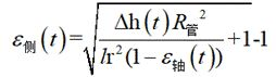
即为应力波加载到
t时刻时试件的侧向应变。
(1)煤岩等脆性材料试件在受到动载冲击时的侧向应变是不均匀的,本发明将测量试件的侧向应变信息巧妙的转变为测量液体的体积变化信息,再根据液体体积变化信息结合试件基本信息换算出试件的侧向应变,测量方法合理,测量结果准确。
(2)煤岩类试件受动载时侧向应变率较高,以往采用粘贴应变片的方法很容易造成应变片断路,导致数据缺失,本发明采用液体体积转换的方法间接测量试件的侧向应变,避免了采用应变片测量的不足,测量方法更加可靠。
(3)煤岩类试件测量时,其表面为粗糙的曲面,手工粘贴应变片的方法常因粘贴角度不合适,或粘贴不牢固而不能捕获到试件真实的侧向应变,本发明避免了煤岩试件不光滑的曲面的影响以及人工误差,测量精度明显提高。
(4)本发明装置测量原理简单,操作方便,且可以重复使用。
下面结合附图与具体实施方式对本发明作进一步说明:
图1为本发明一种通过液体体积测量试件动态侧向应变的装置结构原理示意图;
图2为本发明装置在SHPB试验系统中的装配总图;
图3为本发明装置中固定装置的结构示意图;
图4为本发明装置中转换装置的结构示意图;
图5为本发明装置中采集装置的结构示意图;
图6为本发明中试件的参数标注示意图;
图7为本发明测量方法的实验流程图。
图中:1-底座,2-活柱,3-弧形托板,4-进液孔,5-缸体,6-入射杆侧盖板,7-橡胶垫圈,8-入射杆,9-待测试件,10-高程信号传感器,11-透射杆,12-透射杆侧盖板,13-橡胶皮套,14-第一出液孔,15-量管,16-导线,17-高速动态信号采集仪,18-计算机,19-垂直分布光源,20-传感器外壳,21-垂直分布感光元件,22-转换装置,23-固定装置,24-动载冲击装置,25-SHPB实验装置基座,26-采集装置,27-第二出液孔,28-连通件。
分离式霍普金森压杆实验系统是研究中高应变率(10
2~10
4)下材料力学性能的最主要的实验方法,是爆炸与冲击动力学实验技术中重要组成成分。针对现有常用往试件侧面贴应变片的方法获得试件侧向应变的局限性,本发明提出了一种通过液体体积测量试件动态侧向应变的装置及方法。本发明利用试件在受动态冲击时试件侧面体积的膨胀,巧妙地将试件受动载时侧面体积的变化转换为液体体积的变化,进而获得试件受动载过程中动态的侧向应变参数。与传统手工贴应变片的方式相比,本发明实现原理简单,大大提高了测量精度,并且本发明装置可以重复使用,总体来说具有经济型。
下面结合附图对本发明装置及方法进行更为具体地说明。
结合附图,一种通过液体体积测量试件动态侧向应变的装置,包括转换装置22、采集装置26和固定装置23,转换装置用于将待测试件的动态侧向应变信息转化为液体高程动态变化信息,具体地是通过密闭缸体等部件,将试件在受动态冲击时侧面体积的膨胀,转换为量管内液体高程的变化。采集装置26用于实时获取液体高程动态变化信息,具体地是通过高程信号传感器获得量管内液体高程动态变化信息,再通过计算机处理最终获得试件的实时动态侧向应变。固定装置23用于将转换装置固定在SHPB实验台上,保证在进行动载实验时转换装置不会发生移动造成实验误差,而且固定装置可调节转换装置的竖直高度,使缸体处于合适高度。
所述转换装置22包括缸体5、入射杆侧盖板6、透射杆侧盖板12和橡胶皮套13,缸体5呈空心圆筒状,水平布置,缸体的两端分别与入射杆侧盖板6和透射杆侧盖板12螺纹连接,以上两侧盖板均为圆形,中部有一略大于入射杆8或透射杆11直径的圆孔,以方便入射杆或透射杆穿过并移动。在缸体5与盖板之间还设置有用于缸体内部空间密封的橡胶垫圈7,橡胶垫圈7具体为圆环形橡胶垫片,其固定在缸体5的端面与盖板内侧面之间,橡胶垫圈的内环与穿过的入射杆或透射杆紧密接触,起到密封作用,保证两侧盖板与缸体5形成密闭的储液空间。
待测试件9加工成圆柱状,直径与入射杆8或透射杆11的直径相等。橡胶皮套13套在待测试件的外侧,并将待测试件紧紧包裹。待测试件置于缸体内部中心处,待测试件的两端分别与入射杆和透射杆的端部相抵触。待测试件侧面包裹橡胶皮套的目的是将试件与缸体内充注的液体隔绝,消除液体对试件侧向应变的影响。这样通过橡胶皮套将试件的侧面包裹,通过入射杆和透射杆将试件的两端掩盖,可使得试件与缸体内的液体完全隔绝,在实验过程中不用考虑试件材料会否与缸体内的液体发生吸附等问题,保证了实验结果的准确性。
在缸体的底部两侧开设有进液孔4和第一出液孔14,在缸体的顶部开设有第二出液孔27,进液孔4和第一出液孔14与输液管路连接。在缸体的上方设置有量管15,量管15为两端敞口的透明玻璃管,竖直放置,量管15的底部与第二出液孔27相连通。
所述采集装置26包括高程信号传感器10和高速动态信号采集仪17,高程信号传感器10包括传感器外壳20,传感器外壳20套设在量管15的外部,在传感器外壳的一侧布置有垂直分布光源19,在传感器外壳的另一侧布置有垂直分布感光元件21。高程信号传感器10通过导线16与高速动态信号采集仪17连接,高速动态信号采集仪17通过导线与计算机18连接。
所述传感器外壳20为不透光的黑色外壳,可以阻隔外部光线对感光元件的干扰。所述缸体内的液体可选择不透光的黑色液体等。这样垂直分布光源19射出的光线通过透明量管15后由垂直分布感光元件21接收到,可以将量管内液体的高程信号转化为电信号,再由数据线传输到高速动态信号采集仪中,最终传输到计算机中形成高程随时间变化的曲线,经过处理得到试件的侧向应变随时间变化的曲线。
所述固定装置23包括底座1、活柱2和弧形托板3,底座1为长板型,两侧开有两孔,可以通过螺栓固定在SHPB实验装置基座25上。活柱2的底端与底座连接,活柱2的顶端与弧形托板3连接,弧形托板3与缸体的底部连接。在活柱上配置有调节螺栓,用于调节活柱的升降,以保证被测试件与SHPB波导杆(入射杆和透射杆)满足同一高度。
作为对本发明的进一步设计,在第二出液孔处设置有连通件28,连通件28呈倒T形结构,在连通件的内部竖向设置有贯通的连通孔,连通件的底部与缸体的顶部连接,连通件的上部插入量管15中,且连通件将量管的底端敞口密封。缸体5内的液体经连通件28进入量管15中。连通件28的设置既方便了缸体与量管的连通,又方便了量管的安装固定。
更进一步的,所述入射杆侧盖板6与透射杆侧盖板12的外表面均设置成磨砂面,便于装卸。
进一步的,上述橡胶皮套的两端设置有向外突出的圆环,橡胶皮套的伸展方向与圆环所处于的平面相垂直。这样在盖板与缸体之间进行螺纹连接时,橡胶皮套的圆环和橡胶垫圈一并置于盖板内侧和缸体端面之间,由盖板和缸体压紧,可进一步起到缸体内部的密封效果。
更进一步的,所述进液孔4和第一出液孔14分别与输液管路的进液管和出液管之间采用锥形螺纹连接,锥形螺纹可以实现过盈配合,保证密封性。
本发明还提供一种通过液体体积测量试件动态侧向应变的方法。试件在受到动载冲击时,产生动态的侧向应变,但试件在受动载时的侧向应变是不均匀的,本发明方法巧妙的将测量试件的侧向应变转移到测量液体体积的变化,再根据液体体积的动态变化换算获得试件的动态侧向应变。
一种通过液体体积测量试件动态侧向应变的方法,采用如上所述的装置,包括以下步骤:
第一步,将待测试件9加工成圆柱形,测量并记录待测试件的径向半径和轴向长度。
第二步,将转换装置22放置在SHPB实验装置的基座上,并置于夹持试件位置处,通过固定装置的活柱2调节转换装置的缸体5至合适高度。将待测试件9安置于橡胶皮套13内,并将试件与橡胶皮套置于缸体5内部,且试件通过SHPB实验装置中的入射杆8与透射杆11夹紧。
第三步,安装好采集装置26,打开高程信号传感器10和高速动态信号采集仪17,打开进液孔4和第二出液孔27,关闭第一出液孔14,由进液孔向缸体内部注入黑色液体,直到高程信号传感器10开始收到信号。
第四步,关闭进液孔4,启动SHPB实验装置的冲击加载系统(包括动载冲击装置24),发射子弹开始动载实验,高程信号传感器10将量管内液体的高程信号转化为电信号,然后传输到高速动态信号采集仪17中。
第五步,由计算机保存高速动态信号采集仪采集到的数据,形成高程随时间变化的曲线,再结合量管内半径,试件原始径向半径和轴向长度,换算出在一次动载冲击中试件侧向应变随时间变化的曲线。
第六步,打开第一出液孔14,回收缸体内液体,然后拧开两侧盖板即入射杆侧盖板6和透射杆侧盖板12,将缸体5取下,将试件从橡胶皮套中取出,清理试验台。
上述第五步中所述的高程随时间变化的曲线与侧向应变随时间变化的曲线采用以下步骤换算:
假设由高速动态信号采集仪采集到的由高程信号传感器获得的动态高程变化为△h(
t),由于试件受到动载冲击产生的侧向扩容体积为
V
侧,量管内获得的液体体积增量为
V
量,计圆柱形试件的原长为
l,试件原始半径为
r,量管内半径为
R
管,应力波加载到
t时刻,轴向应变为
ε
轴(
t),侧向应变为
ε
侧(
t),则:
V 侧=
π{[
r(1+
ε 侧(
t))]
2-
r 2}×
l (1-
ε
侧(
t))
V 量=
π R 管 2 ×△h(
t)
由于缸体内部与量管相通,且量管与大气相通,故试件由于受动载冲击造成侧向应变增加的体积等于量管内部增加的液体体积,即
V 量=
V 侧
通过换算得到:
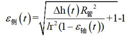
即为应力波加载到
t时刻时试件的侧向应变。
上述方式中未述及的部分采取或借鉴已有技术即可实现。
需要说明的是,在本说明书的教导下,本领域技术人员所作出的任何等同替代方式,或明显变型方式,均应在本发明的保护范围之内。
Claims (7)
- 一种通过液体体积测量试件动态侧向应变的装置,其特征在于:包括用于将待测试件的动态侧向应变信息转化为液体高程动态变化信息的转换装置,用于实时获取液体高程动态变化信息的采集装置,以及用于将转换装置固定在SHPB实验台上且调节转换装置竖直高度的固定装置;所述转换装置包括缸体、盖板和橡胶皮套,缸体呈空心圆筒状,水平布置,缸体的两端分别与盖板螺纹连接,在盖板的中心设置有供入射杆或透射杆穿过的圆孔,在缸体与盖板之间还设置有用于缸体内部空间密封的橡胶垫圈;待测试件呈圆柱状,所述橡胶皮套套在待测试件的外侧,并将待测试件紧紧包裹,待测试件置于缸体内部中心处,待测试件的两端分别与入射杆和透射杆的端部相抵触;在缸体的底部两侧开设有进液孔和第一出液孔,在缸体的顶部开设有第二出液孔,进液孔和第一出液孔与输液管路连接,在缸体的上方设置有量管,量管为两端敞口的透明玻璃管,竖直放置,量管的底部与第二出液孔相连通;所述采集装置包括高程信号传感器和高速动态信号采集仪,高程信号传感器包括传感器外壳,传感器外壳套设在量管的外部,在传感器外壳的一侧布置有垂直分布光源,在传感器外壳的另一侧布置有垂直分布感光元件;高程信号传感器通过导线与高速动态信号采集仪连接,高速动态信号采集仪与计算机连接;所述固定装置包括底座、活柱和弧形托板,底座固定在SHPB试验台上,活柱的底端与底座连接,活柱的顶端与弧形托板连接,弧形托板与缸体的底部连接,在活柱上配置有用于调节活柱升降的调节螺栓。
- 根据权利要求1所述的一种通过液体体积测量试件动态侧向应变的装置,其特征在于:在第二出液孔处设置有连通件,连通件呈倒T形结构,在连通件的内部竖向设置有贯通的连通孔,连通件的底部与缸体的顶部连接,连通件的上部插入量管中,且连通件将量管的底端敞口密封。
- 根据权利要求1所述的一种通过液体体积测量试件动态侧向应变的装置,其特征在于:所述盖板的外表面设置成磨砂面。
- 根据权利要求1所述的一种通过液体体积测量试件动态侧向应变的装置,其特征在于:所述进液孔和第一出液孔与输液管路之间采用锥形螺纹连接。
- 根据权利要求1所述的一种通过液体体积测量试件动态侧向应变的装置,其特征在于:所述传感器外壳为不透光的黑色外壳。
- 一种通过液体体积测量试件动态侧向应变的方法,采用如权利要求1-5中任一权利要求所述的装置,其特征在于包括以下步骤:第一步,将待测试件加工成圆柱形,测量并记录待测试件的径向半径和轴向长度;第二步,将转换装置放置在SHPB试验台的夹持试件位置处,通过固定装置的活柱调节转换装置的缸体至合适高度;将试件安置于橡胶皮套内,并将试件与橡胶皮套置于缸体内部,且试件通过SHPB实验装置中的入射杆与透射杆夹紧;第三步,安装好采集装置,打开高程信号传感器和高速动态信号采集仪,打开进液孔和第二出液孔,关闭第一出液孔,由进液孔向缸体内部注入液体,直到高程信号传感器开始收到信号;第四步,关闭进液孔,启动SHPB实验装置的冲击加载系统,发射子弹开始动载实验,高程信号传感器将量管内液体的高程信号转化为电信号,然后传输到高速动态信号采集仪中;第五步,由计算机保存高速动态信号采集仪采集到的数据,形成高程随时间变化的曲线,再结合量管内半径,试件原始径向半径和轴向长度,换算出在一次动载冲击中试件侧向应变随时间变化的曲线;第六步,打开第一出液孔,回收缸体内液体,然后拧开两侧盖板,将缸体取下,将试件从橡胶皮套中取出,清理试验台。
- 根据权利要求6所述的一种通过液体体积测量试件动态侧向应变的方法,其特征在于,第五步中所述的高程随时间变化的曲线与侧向应变随时间变化的曲线采用以下步骤换算:假设由高速动态信号采集仪采集到的由高程信号传感器获得的动态高程变化为△h( t),由于试件受到动载冲击产生的侧向扩容体积为 V 侧,量管内获得的液体体积增量为 V 量,计圆柱形试件的原长为 l,试件原始半径为 r,量管内半径为 R 管,应力波加载到 t时刻,轴向应变为 ε 轴( t),侧向应变为 ε 侧( t),则:V 侧= π{[ r(1+ ε 侧( t))] 2- r 2}× l (1- ε 侧( t))V 量= πR 管 2 ×△h( t)由于缸体内部与量管相通,且量管与大气相通,故试件由于受动载冲击造成侧向应变增加的体积等于量管内部增加的液体体积,即V 量= V 侧通过换算得到:即为应力波加载到 t时刻时试件的侧向应变。
Applications Claiming Priority (2)
| Application Number | Priority Date | Filing Date | Title |
|---|---|---|---|
| CN201911085119.2 | 2019-11-08 | ||
| CN201911085119.2A CN110926937B (zh) | 2019-11-08 | 2019-11-08 | 一种通过液体体积测量试件动态侧向应变的装置及方法 |
Publications (1)
| Publication Number | Publication Date |
|---|---|
| WO2021088239A1 true WO2021088239A1 (zh) | 2021-05-14 |
Family
ID=69852480
Family Applications (1)
| Application Number | Title | Priority Date | Filing Date |
|---|---|---|---|
| PCT/CN2019/129987 Ceased WO2021088239A1 (zh) | 2019-11-08 | 2019-12-30 | 一种通过液体体积测量试件动态侧向应变的装置及方法 |
Country Status (2)
| Country | Link |
|---|---|
| CN (1) | CN110926937B (zh) |
| WO (1) | WO2021088239A1 (zh) |
Families Citing this family (1)
| Publication number | Priority date | Publication date | Assignee | Title |
|---|---|---|---|---|
| CN112539992B (zh) * | 2020-12-02 | 2021-10-29 | 山东科技大学 | 霍普金森压杆实验多级脉冲加载装置及其实验方法 |
Citations (6)
| Publication number | Priority date | Publication date | Assignee | Title |
|---|---|---|---|---|
| JPS57199937A (en) * | 1981-06-03 | 1982-12-08 | Chiyoda Chem Eng & Constr Co Ltd | Tester for stress relieving |
| CN104198291A (zh) * | 2014-08-11 | 2014-12-10 | 太原理工大学 | 一种测量岩石试样径向变形的装置 |
| CN204389284U (zh) * | 2015-02-13 | 2015-06-10 | 洛阳利维科技有限公司 | 一种新型霍普金森压杆主动围压实验的围压缸装置 |
| CN106525598A (zh) * | 2016-12-05 | 2017-03-22 | 中国石油大学(华东) | 一种简易的岩石三轴压缩试验仪器 |
| CN106644750A (zh) * | 2016-12-07 | 2017-05-10 | 凌贤长 | 开放系统冻融土动静三轴测试仪 |
| RU2697416C1 (ru) * | 2019-02-08 | 2019-08-14 | Константин Викторович Торопецкий | Способ определения реологических характеристик и длительной прочности материалов |
Family Cites Families (13)
| Publication number | Priority date | Publication date | Assignee | Title |
|---|---|---|---|---|
| SU947689A1 (ru) * | 1980-08-18 | 1982-07-30 | Одесский технологический институт пищевой промышленности им.М.В.Ломоносова | Устройство дл испытани сыпучих материалов |
| CN1877267A (zh) * | 2006-07-07 | 2006-12-13 | 田逸 | 激光传导、数字量化液位测量方法 |
| CN101963556A (zh) * | 2010-08-24 | 2011-02-02 | 清华大学 | 等应变增量比试验系统 |
| CN102331366B (zh) * | 2011-07-18 | 2012-10-24 | 河海大学 | 一种稳压的霍普金森杆主动围压装置 |
| CN202531056U (zh) * | 2012-04-05 | 2012-11-14 | 中国石油天然气股份有限公司 | 可调式管杆架支墩 |
| CN202837110U (zh) * | 2012-06-07 | 2013-03-27 | 云南蒙新高速公路建设指挥部 | 一种新型岩土边坡生态防护变形试验装置 |
| CN106813751A (zh) * | 2015-12-02 | 2017-06-09 | 田荣侠 | 一种高精度玻璃管液位自动检测装置 |
| CN205192571U (zh) * | 2015-12-18 | 2016-04-27 | 东莞理工学院 | 一种基于ccd的液位测量装置 |
| CN105758704B (zh) * | 2016-02-23 | 2018-12-14 | 繁昌县菲德通讯材料设计有限公司 | 一种霍普金森压杆围压测试装置 |
| CN207816727U (zh) * | 2017-12-20 | 2018-09-04 | 北京科技大学 | 一种便携式自密封岩石shpb试验围压加压装置 |
| CN107966371A (zh) * | 2017-12-20 | 2018-04-27 | 北京科技大学 | 一种便携式自密封岩石shpb试验围压加压装置 |
| CN108995500A (zh) * | 2018-08-06 | 2018-12-14 | 施彦春 | 一种避免挤压的汽车空调管用固定装置 |
| CN209115811U (zh) * | 2018-10-06 | 2019-07-16 | 西南石油大学 | 一种石油机械用管道固定装置 |
-
2019
- 2019-11-08 CN CN201911085119.2A patent/CN110926937B/zh active Active
- 2019-12-30 WO PCT/CN2019/129987 patent/WO2021088239A1/zh not_active Ceased
Patent Citations (6)
| Publication number | Priority date | Publication date | Assignee | Title |
|---|---|---|---|---|
| JPS57199937A (en) * | 1981-06-03 | 1982-12-08 | Chiyoda Chem Eng & Constr Co Ltd | Tester for stress relieving |
| CN104198291A (zh) * | 2014-08-11 | 2014-12-10 | 太原理工大学 | 一种测量岩石试样径向变形的装置 |
| CN204389284U (zh) * | 2015-02-13 | 2015-06-10 | 洛阳利维科技有限公司 | 一种新型霍普金森压杆主动围压实验的围压缸装置 |
| CN106525598A (zh) * | 2016-12-05 | 2017-03-22 | 中国石油大学(华东) | 一种简易的岩石三轴压缩试验仪器 |
| CN106644750A (zh) * | 2016-12-07 | 2017-05-10 | 凌贤长 | 开放系统冻融土动静三轴测试仪 |
| RU2697416C1 (ru) * | 2019-02-08 | 2019-08-14 | Константин Викторович Торопецкий | Способ определения реологических характеристик и длительной прочности материалов |
Also Published As
| Publication number | Publication date |
|---|---|
| CN110926937B (zh) | 2020-09-08 |
| CN110926937A (zh) | 2020-03-27 |
Similar Documents
| Publication | Publication Date | Title |
|---|---|---|
| CN110926936B (zh) | 一种基于shpb试验系统的试件动态侧向应变测量装置及方法 | |
| US5025668A (en) | Cell for the triaxial stress testing of a rock sample and a testing method using such a cell | |
| CN104913976B (zh) | 一种温度可控的岩石单轴压缩声发射试验装置及试验方法 | |
| CN103499491B (zh) | 一种多轴加载系统及加载方法 | |
| CN112228779A (zh) | 一种核电化工管道冰塞隔离测试装置 | |
| CN110082222A (zh) | 分体式三维压力装置及应变波形图采集方法 | |
| CN111141459A (zh) | 模拟耦合工况下法兰垫片密封性能的试验装置 | |
| CN103983533A (zh) | 一种含气页岩裂隙演化与渗流特征测试装置及方法 | |
| CN108005131A (zh) | 一种地下围护结构体变形实时监测系统及其监测方法 | |
| WO2021088239A1 (zh) | 一种通过液体体积测量试件动态侧向应变的装置及方法 | |
| CN113063665B (zh) | 岩石三轴蠕变试验装置及其系统 | |
| CN207689276U (zh) | 一种用于混凝土圆柱体试样应变测试的标距装置 | |
| CN207007609U (zh) | 一种温控式单轴拉伸试验装置 | |
| CN213746167U (zh) | 一种核电化工管道冰塞隔离测试装置 | |
| CN111964733B (zh) | 一种对称泄压瓦斯破煤条件下数-图实时监测实验装置 | |
| CN212674050U (zh) | 一种二次杠杆式测量微小变形的引伸计 | |
| CN110207640A (zh) | 一种单裂隙微米级隙宽测量结构及其安装方法、测量方法 | |
| CN214749418U (zh) | 岩石三轴蠕变试验装置及其系统 | |
| CN216433768U (zh) | 一种深水压力模拟测试工装 | |
| CN217304658U (zh) | 一种高强度钢试样延迟断裂试验装置 | |
| CN207488093U (zh) | 一种煤岩多场耦合监测试验装置 | |
| CN115342970A (zh) | 压力变送器的校验装置 | |
| CN210719899U (zh) | 一种侧插探针式三轴土样制样装置 | |
| WO2023213040A1 (zh) | 一种回旋耐压壳等效模拟试验装置及试验方法 | |
| CN115371880A (zh) | 一种薄膜式压力传感器动态标定装置及其使用方法 |
Legal Events
| Date | Code | Title | Description |
|---|---|---|---|
| 121 | Ep: the epo has been informed by wipo that ep was designated in this application |
Ref document number: 19952116 Country of ref document: EP Kind code of ref document: A1 |
|
| NENP | Non-entry into the national phase |
Ref country code: DE |
|
| 122 | Ep: pct application non-entry in european phase |
Ref document number: 19952116 Country of ref document: EP Kind code of ref document: A1 |