WO2021085588A1 - Propeller - Google Patents
Propeller Download PDFInfo
- Publication number
- WO2021085588A1 WO2021085588A1 PCT/JP2020/040775 JP2020040775W WO2021085588A1 WO 2021085588 A1 WO2021085588 A1 WO 2021085588A1 JP 2020040775 W JP2020040775 W JP 2020040775W WO 2021085588 A1 WO2021085588 A1 WO 2021085588A1
- Authority
- WO
- WIPO (PCT)
- Prior art keywords
- propeller
- obstacle
- hub
- lift
- bent portion
- Prior art date
Links
Images


Classifications
-
- B—PERFORMING OPERATIONS; TRANSPORTING
- B63—SHIPS OR OTHER WATERBORNE VESSELS; RELATED EQUIPMENT
- B63H—MARINE PROPULSION OR STEERING
- B63H1/00—Propulsive elements directly acting on water
- B63H1/02—Propulsive elements directly acting on water of rotary type
- B63H1/12—Propulsive elements directly acting on water of rotary type with rotation axis substantially in propulsive direction
- B63H1/14—Propellers
- B63H1/26—Blades
-
- B—PERFORMING OPERATIONS; TRANSPORTING
- B64—AIRCRAFT; AVIATION; COSMONAUTICS
- B64C—AEROPLANES; HELICOPTERS
- B64C11/00—Propellers, e.g. of ducted type; Features common to propellers and rotors for rotorcraft
- B64C11/02—Hub construction
- B64C11/04—Blade mountings
- B64C11/08—Blade mountings for non-adjustable blades
- B64C11/12—Blade mountings for non-adjustable blades flexible
-
- B—PERFORMING OPERATIONS; TRANSPORTING
- B64—AIRCRAFT; AVIATION; COSMONAUTICS
- B64C—AEROPLANES; HELICOPTERS
- B64C11/00—Propellers, e.g. of ducted type; Features common to propellers and rotors for rotorcraft
- B64C11/16—Blades
- B64C11/20—Constructional features
-
- B—PERFORMING OPERATIONS; TRANSPORTING
- B64—AIRCRAFT; AVIATION; COSMONAUTICS
- B64C—AEROPLANES; HELICOPTERS
- B64C27/00—Rotorcraft; Rotors peculiar thereto
- B64C27/32—Rotors
- B64C27/35—Rotors having elastomeric joints
-
- B—PERFORMING OPERATIONS; TRANSPORTING
- B64—AIRCRAFT; AVIATION; COSMONAUTICS
- B64C—AEROPLANES; HELICOPTERS
- B64C27/00—Rotorcraft; Rotors peculiar thereto
- B64C27/32—Rotors
- B64C27/46—Blades
- B64C27/473—Constructional features
-
- F—MECHANICAL ENGINEERING; LIGHTING; HEATING; WEAPONS; BLASTING
- F04—POSITIVE - DISPLACEMENT MACHINES FOR LIQUIDS; PUMPS FOR LIQUIDS OR ELASTIC FLUIDS
- F04D—NON-POSITIVE-DISPLACEMENT PUMPS
- F04D29/00—Details, component parts, or accessories
- F04D29/26—Rotors specially for elastic fluids
- F04D29/28—Rotors specially for elastic fluids for centrifugal or helico-centrifugal pumps for radial-flow or helico-centrifugal pumps
- F04D29/30—Vanes
Definitions
- the present invention relates to a propeller.
- An airplane propeller is a device that includes a plurality of rotary blades (blades) attached to a rotating shaft, and obtains thrust or lift by rotating these blades.
- Propellers are also used in small unmanned aerial vehicles, so-called drones.
- Patent Document 1 describes a propeller provided with a rotary blade having a shape suitable for hovering a drone.
- This propeller comprises a rotor with long chords near the axis of rotation and stability suitable for hovering.
- Patent Document 2 describes a propeller made of a flexible material.
- the rotating shaft and rotor blades of this propeller are made of a flexible material.
- the propeller described in Patent Document 1 includes a wing having a shape optimized for maximizing flight time and load.
- the wings of this propeller are formed into an unchanging shape for maximum flight time and load. Therefore, the rigidity of the propeller described in Patent Document 1 is high, and there is a problem that the wing is permanently deformed when the propeller collides with another object.
- an object of the present invention is to provide a propeller that easily returns to its original shape even if it is deformed during rotation.
- the propeller according to one aspect of the present invention is In the center and A blade formed so as to extend outward from the central portion, A bent portion including a flexible member connecting the central portion and the blade, and a bent portion. Fibers arranged inside the bent portion and stretched between the central portion and the blades, and To be equipped.
- the blade of the propeller according to the present invention includes a front edge portion located on the front side in the rotation direction.
- the front edge portion may have flexibility.
- a propeller that easily returns to its original shape even if it is deformed during rotation is provided.
- FIG. 1A It is a perspective view of the propeller which concerns on 1st Embodiment. It is a top view of the propeller shown in FIG. 1A. It is a front view of the propeller shown in FIG. 1A. It is a side view of the propeller shown in FIG. 1A. It is a flowchart which shows the flow of the manufacturing method of the propeller shown in FIG. 1A. It is a perspective view of the propeller which concerns on a comparative example. It is a graph which shows the measurement result of the experiment which compared the propeller shown in FIG. 1A and the propeller shown in FIG. 3A. It is a figure which shows the image before and after the propeller shown in FIG. 1A comes into contact with an obstacle.
- FIG. 1A It is a figure which shows the image immediately after the propeller shown in FIG. 1A came into contact with an obstacle. It is another figure which shows the image immediately after the propeller shown in FIG. 1A comes into contact with an obstacle. It is another figure which shows the image immediately after the propeller shown in FIG. 1A comes into contact with an obstacle. It is another figure which shows the image immediately after the propeller shown in FIG. 1A comes into contact with an obstacle. It is another figure which shows the image immediately after the propeller shown in FIG. 1A comes into contact with an obstacle. It is a top view of the propeller which concerns on another comparative example. It is a top view of the propeller which concerns on another comparative example. It is a top view of the propeller which concerns on another comparative example. FIG.
- FIG. 7B is a diagram showing an image immediately after the propeller shown in FIG. 7B comes into contact with an obstacle. It is a figure which shows the image immediately after the propeller shown in FIG. 7C came into contact with an obstacle. It is a figure which shows the image immediately after the propeller shown in FIG. 7A came into contact with an obstacle. It is a graph which shows the measurement result of another experiment which compares propellers shown in FIG. 7A to FIG. 7C. It is a top view of the propeller which concerns on another comparative example. It is a top view of the propeller which concerns on another comparative example. It is a top view of the propeller which concerns on another comparative example. It is a graph which shows the simulation result which compares propellers shown in FIGS.
- FIG. 9A to 9C It is a perspective view of the propeller which concerns on another comparative example. It is a figure which shows the position of the tip of the wing part of the propeller shown in FIG. 7B. It is a figure which shows the position of the tip of the wing part of the propeller shown in FIG. 10A. It is another figure which shows the position of the tip of the wing part of the propeller shown in FIG. 7B. It is another figure which shows the position of the tip of the wing part of the propeller shown in FIG. 10A. It is a graph which shows the measurement result of another experiment which compares the propeller shown in FIG. 7B and the propeller shown in FIG. 10A. It is a graph which compares the lift measured by an experiment with the predicted lift.
- the propeller 1 according to the first embodiment of the present invention is, for example, a two-blade propeller attached to a drone.
- the propeller 1 bends a hub 11 which is a central portion capable of rotating, a wing portion 12 including a pair of blades extending outward from the hub 11, and the hub 11 and the wing portion 12.
- a flexion portion 13 that is possibly connected, a deformable edge 14 provided at the edge of the wing portion 12, and a plurality of fibrous tendons 15 that are embedded in the flexion portion 13 and connect the hub 11 and the wing portion 12 To be equipped.
- the extending direction of the wing portion 12 shown in FIG. 1A will be described as the + Y direction
- the direction in which lift is generated will be described as the + Z direction
- the directions perpendicular to the Y and Z directions will be described as the + X direction.
- the hub 11 is arranged at the center of the propeller 1.
- the hub 11 is a central portion that connects the rotation axis of the propeller 1 with other members of the propeller 1.
- a hole H for connecting to the rotation shaft of the motor M (not shown) is threaded in the Z direction.
- the hub 11 includes an annulus R and a transition portion T formed so as to continuously and smoothly project radially outward from the annulus R. At one end of the transition portion T, the hub 11 is connected to the bent portion 13.
- the hub 11 contains a rigid plastic material having high rigidity, for example, ABS resin or PLA (polylactic acid) resin.
- the wing portion 12 contains a highly rigid hard plastic material.
- the blade portion 12 is formed in a shape that functions as a rotary blade (blade) of the propeller 1 integrally with the deformable edge 14 described later.
- the specific shape of the propeller 1 may be calculated theoretically or by simulation, and is not limited to the shapes shown in FIGS. 1A to 1D.
- the bent portion 13 contains a material having higher flexibility than the hub 11 and the wing portion 12, for example, silicone rubber. Further, the rigidity of the bent portion 13 is lower than the rigidity of the hub 11 and the wing portion 12.
- the bent portion 13 is arranged between the hub 11 and the wing portion 12, and is formed in a continuously changing shape that smoothly connects the transition portion T located on the outside of the hub 11 and the inside of the wing portion 12. Has been done. By bending the bent portion 13, the wing portion 12 can be displaced in the vertical direction and the rotational direction.
- the deformable edge 14 is a front edge portion provided on the edge of the wing portion 12 in the rotation direction D.
- the rotation direction D is counterclockwise in the propeller 1.
- the deformable edge 14, like the bent portion 13, contains a material that is more flexible than the hub 11 and the wing portion 12, such as silicone rubber.
- the rigidity of the deformable edge 14 is lower than the rigidity of the hub 11 and the wing portion 12.
- the wing portion 12 is an example of the rear wing portion in the claim
- the deformable edge 14 is an example of the front edge portion in the claim.
- the tendon 15 is a thread-like member containing a flexible and high-strength fiber material, for example, nylon fiber. As shown by the broken line in FIGS. 1A to 1C, a plurality of tendons 15 are stretched between the hub 11 and the wing portion 12, and the periphery thereof is covered with the flexion portion 13. The rigidity of the tendon 15 is lower than the rigidity of the flexion portion 13, and the flexibility of the tendon 15 is higher than the flexibility of the flexion portion 13.
- the hub 11 and the wing portion 12 have low flexibility, while the bent portion 13 has high flexibility and the tendon 15 having high strength connects the wing portion 12 to the hub 11. There is. Therefore, when the propeller 1 receives an external force, the wing portion 12 and the deformable edge 14 are displaced by the external force, but when the external force disappears, the wing portion 12 and the deformable edge 14 are quickly returned to their original positions. Further, since the propeller 1 contains only a partially flexible material, twisting and vibration due to rotation are reduced as compared with the case where the propeller 1 is entirely composed of the flexible material.
- step S1 the shape of the propeller 1 is designed (step S1). Specifically, for example, using numerical calculation software, a simulator, CAD (Computer Aided Design) software, etc., each component of the propeller 1, that is, a hub 11, a wing portion 12, a bending portion 13, a deformable edge 14, and the like can be used. Design the shape.
- CAD Computer Aided Design
- a hard part may be formed by molding using a mold as in the method in the molding step described later without using a 3D printer.
- the hard part and the tendon 15 are adhered to form a frame which is the skeleton of the propeller 1 (step S3). Specifically, since small holes are formed on the surfaces of the hub 11 and the wing portion 12 facing each other, the tendon 15 coated with the adhesive is inserted into these small holes and fixed. For adhesion, an adhesive suitable for both the hard part and the tendon 15 is used.
- step S3 The frame formed in step S3 is placed on the mold and positioned (step S4).
- the mold used in this step is formed in advance by a method such as 3D printing from the data of the space occupied by the hub 11, the wing portion 12, the bending portion 13, and the deformable edge 14 generated in the design step.
- step S5 For example, a mixture of the main material and the curing agent is poured into a mold and gently held until it hardens.
- step S6 Separate the molded product from the mold (step S6). In this step, excess parts, so-called burrs, are removed from the molded product.
- Fine adjustment is performed by applying an adhesive to the mutually contacting portions of the hub 11, the wing portion 12, the bent portion 13, and the deformable edge 14 (step S7). As a result, the hard part and the soft part of the propeller 1 are more firmly connected. Propeller 1 is completed through the above steps.
- the propeller was connected to the rotation shaft of the motor M, and the rotation speed of the motor M could be set arbitrarily by changing the current supplied to the motor M.
- the rotation speed of the propeller is equal to the rotation speed of the motor M.
- FIG. 3B shows the relationship of lift (N) with respect to the rotational speed (rpm) of the motor M.
- the lift generated by the propeller 1 is linearly increased as in the lift generated by the conventional propeller 101.
- the lift obtained by using the propeller 1 is about 22.6% smaller than the lift obtained by using the conventional propeller 101.
- the rotation speed it was obtained that the lift force of the propeller 1 can be obtained to the same level as that of the conventional propeller 101.
- the lift produced by the flexible propeller 1 is smaller than the lift produced by the conventional propeller 101 having the same shape.
- the flexible propeller 1 can generate lift equivalent to that of the conventional propeller 101. Therefore, even if the conventional propeller 101 is replaced with the flexible propeller 1, it is considered that the flight of the drone will not be hindered.
- 4A-4D and 5A-5D are high-speed camera images taken before and after the moment when the propeller 1 and the propeller 101 touch the ribbon, respectively.
- 4A to 4D and 5A to 5D are all arranged in the order in which time has passed.
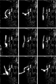
- FIGS. 6A to 6E are high-speed camera images taken after the propeller 1 comes into contact with an obstacle, respectively. 6A to 6E are arranged in the order in which time has passed.
- the images shown in FIGS. 6A and 6B are an image immediately after one of the wing portions 12 of the propeller 1 comes into contact with an obstacle, and an image immediately after the other comes into contact with an obstacle. From these images, it is understood that when the wing portion 12 comes into contact with an obstacle, the propeller 1 bends significantly at the bent portion 13.
- the image shown in FIG. 6C is an image in the process of pulling out an obstacle upward while rotating the propeller 1. From this image, it is understood that the wing portion 12 twists downward to avoid obstacles.
- the images shown in FIGS. 6D and 6E are images immediately after the obstacle is removed. From these images, it is understood that when the obstacle is removed, the shapes of the wing portion 12 and the bent portion 13 are restored.
- the propeller 1 collides with an obstacle and is deformed.
- the time required to return to the original shape is also about 0.4 seconds.
- the bent portion 13 bends, twists, and returns to an obstacle in a relatively short time of less than 1 second. It is understood that the impact force due to contact with is absorbed.
- the bent portions 213 to 413 include a flexible material like the bent portion 13, but are molded using a material that is harder than the bent portion 13.
- FIGS. 8A-8C show changes in shape immediately after the propellers 301, 401, and 201 collide with a resin prism imitating a human finger, respectively.
- “Frame n” represents an image at the moment of collision
- “Frame n + 1” represents an image one frame after the moment of collision.
- the temporal intervals between adjacent frames are equal, about 1 millisecond.
- only representative frames are shown in FIGS. 8A-8C.
- the bent portions 213 to 413 are shortened, the time required to return to the original shape after colliding with the obstacle can be shortened, and if the bent portions 213 to 413 are shortened too much, the obstacles can be shortened. It is understood that it becomes vulnerable to.
- FIG. 8D measures the lift generated by the propellers 201 to 401 by changing the rotation speed of the motor M. At almost all motor M speeds, propellers 201, 301, and 401 produced the largest lift in that order.
- propellers 501-701 differ in that they do not have a deformable edge 14.
- the bent portion 813 of the propeller 801 according to the comparative example does not include a tendon.
- the bent portion 813 is arranged so as to overlap the hub 11 and the wing portion 12, and the bent portion 813 and the hub 11 and the bent portion 813 and the wing portion 12 are joined to each other.
- the pin 816 is driven in the direction indicated by the arrow in each of the portion of the bent portion 813 that overlaps with the hub 11 and the portion that overlaps with the wing portion 12.
- the propeller 301 according to the comparative example is formed in the same shape as the propeller 801.
- the propeller 301 includes a tendon 15 at the flexion portion 313 as well as the flexion portion 13.
- the tip of the wing portion 12 of the propeller 301 is a scale of a ruler arranged parallel to the rotation axis and points to 43.5 mm.
- the tip of the wing portion 12 of the propeller 801 is a scale of a ruler arranged parallel to the rotation axis and points to 35.5 mm.
- the tip of the wing portion 12 of the propeller 801 is 8.0 mm lower than that of the propeller 301.
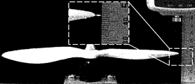
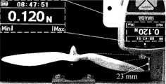
- 11A and 11B are measurements of the magnitude of the force required to deform the tips of the blades 12 of the propellers 801 and 301 until they reach the same position in a stationary state.
- the tip of the wing portion 12 of the propeller 301 was a scale of a ruler arranged parallel to the rotation axis and pointed to 67.0 mm.
- the magnitude of the force required to push down the tip of the wing portion 12 of the propeller 301 to the reference position by 23.0 mm was 0.120 N.
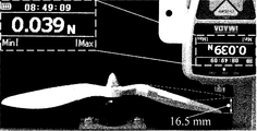
- the tip of the wing portion 12 of the propeller 801 was a scale of a ruler arranged parallel to the rotation axis and pointed to 58.5 mm.
- the magnitude of the force required to push down the tip of the wing portion 12 of the propeller 801 to the reference position by 16.5 mm was 0.039 N.
- the magnitude of the force required to deform the propeller 301 with the tendon 15 to the reference position is about 3 the magnitude of the force required to deform the propeller 801 without the tendon to the same reference position. It is understood to be double. Therefore, it is understood that the tendon 15 contributes to improving the rigidity of the propeller 1. Further, it is presumed that the material of the bent portion 13, the material and diameter of the tendon 15, the number of tendons 15, and the like affect the rigidity of the propeller 1.
- the propeller 801 generated a smaller lift than the propeller 301 in the rotating state. Further, it was obtained that the difference in the magnitude of the lift generated by the propeller 801 and the propeller 301 increases as the rotation speed of the motor M increases. Further, at a rotation speed of the motor M exceeding 2000 rpm, the flexion portion 813 of the propeller 801 without the tendon 15 is damaged, so that the measurement itself cannot be performed. It is considered that these results were obtained because the propeller 801 without the tendon 15 is more strongly affected by the centrifugal force as the rotation speed of the motor M increases as compared with the propeller 301 with the tendon 15. Be done. Therefore, it is understood that the tendon 15 maintains the shape of the entire propeller 1 at a high rotation speed and contributes to improving the lift of the propeller 1.
- 11D and 11E compare the magnitude of lift generated by the propellers 801 and 301 with the simulation. In the simulation, it was expected that the lift will increase as the rotation speed of the motor M increases. The experimental results are almost in line with the simulation, and as the rotation speed of the motor M increases, the lift generated by the propellers 801 and 301 also increases.
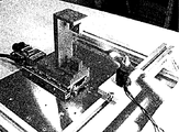
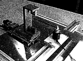
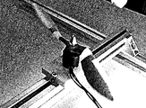
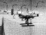
- a hard obstacle RO is connected to the tip of the force sensor FS, and propellers 1 and 101 are attached to the drone DR.
- the propellers 1 and 101 were rotated to fly the drone DR and collide with the collision area CA of the obstacle RO, and the impact force applied to the obstacle by the propellers 1 and 101 was read through the force sensor FS.
- both propellers 1 and 101 applied the maximum impact force to the hard obstacle RO about 3 ms after the moment of collision.
- the maximum impact force given to the hard obstacle RO by the propeller 1 was about 10 N
- the maximum impact force given to the hard obstacle RO by the propeller 101 was about 67 N.
- the magnitude of the impact force applied to the hard obstacle RO by the propeller 1 did not exceed the magnitude of the impact force applied to the hard obstacle RO by the propeller 101.
- Propeller 1 has been described as having two blades, but the number of blades is not limited to this.
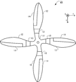
- the propeller 21 according to the second embodiment of the present invention has two pairs of four blades in total.
- the shape of each of these four blades is the same as the blades of the propeller 1, that is, the blade portion 12, the bending portion 13, and the deformable edge 14.
- the four blades are arranged at 90 ° intervals about the rotation axis. According to the propeller 21, since the area of the blades is larger, vibration during flight can be reduced as compared with the propeller 1 having two blades.
Landscapes
- Engineering & Computer Science (AREA)
- Mechanical Engineering (AREA)
- Aviation & Aerospace Engineering (AREA)
- Chemical & Material Sciences (AREA)
- Combustion & Propulsion (AREA)
- Ocean & Marine Engineering (AREA)
- General Engineering & Computer Science (AREA)
- Structures Of Non-Positive Displacement Pumps (AREA)
- Toys (AREA)
Abstract
A propeller (1) is equipped with: a hub (11); a blade (12) formed so as to extend outward from the hub (11); a curved section (13) which includes a flexible member for connecting the hub (11) and the blade (12); and a cord (15) which is positioned inside the curved section (13) and is stretched between the hub (11) and the blade (12). The blade (12) of the propeller (1) includes a deformable edge (14) positioned on the front side thereof in the direction of rotation (D), and said deformable edge (14) may be flexible.
Description
本発明は、プロペラに関する。
The present invention relates to a propeller.
飛行機のプロペラは、回転軸に取り付けられた複数の回転翼(羽根)を備え、これらの羽根が回転することで推力又は揚力を得る装置である。
プロペラは、小型の無人航空機、所謂ドローンにも用いられる。 An airplane propeller is a device that includes a plurality of rotary blades (blades) attached to a rotating shaft, and obtains thrust or lift by rotating these blades.
Propellers are also used in small unmanned aerial vehicles, so-called drones.
プロペラは、小型の無人航空機、所謂ドローンにも用いられる。 An airplane propeller is a device that includes a plurality of rotary blades (blades) attached to a rotating shaft, and obtains thrust or lift by rotating these blades.
Propellers are also used in small unmanned aerial vehicles, so-called drones.
このようなプロペラとして、特許文献1には、ドローンのホバリングに適した形状の回転翼を備えるものが記載されている。
このプロペラは、回転軸近くの翼弦を長く形成してホバリングに適する安定性を有する回転翼を備える。 As such a propeller,Patent Document 1 describes a propeller provided with a rotary blade having a shape suitable for hovering a drone.
This propeller comprises a rotor with long chords near the axis of rotation and stability suitable for hovering.
このプロペラは、回転軸近くの翼弦を長く形成してホバリングに適する安定性を有する回転翼を備える。 As such a propeller,
This propeller comprises a rotor with long chords near the axis of rotation and stability suitable for hovering.
特許文献2には、可撓性を有する材料により構成されているプロペラが記載されている。
このプロペラの回転軸及び回転翼は、可撓性を有する材料で構成されている。 Patent Document 2 describes a propeller made of a flexible material.
The rotating shaft and rotor blades of this propeller are made of a flexible material.
このプロペラの回転軸及び回転翼は、可撓性を有する材料で構成されている。 Patent Document 2 describes a propeller made of a flexible material.
The rotating shaft and rotor blades of this propeller are made of a flexible material.
特許文献1に記載されたプロペラは、飛行時間及び荷重を最大化するために最適化された形状の翼を備える。
このプロペラの翼は、飛行時間及び荷重の最大化のため、変化しない形状に形成される。このため、特許文献1に記載されたプロペラの剛性は高く、プロペラが他の物体に衝突したときに、翼が永続的に変形するという問題がある。 The propeller described inPatent Document 1 includes a wing having a shape optimized for maximizing flight time and load.
The wings of this propeller are formed into an unchanging shape for maximum flight time and load. Therefore, the rigidity of the propeller described inPatent Document 1 is high, and there is a problem that the wing is permanently deformed when the propeller collides with another object.
このプロペラの翼は、飛行時間及び荷重の最大化のため、変化しない形状に形成される。このため、特許文献1に記載されたプロペラの剛性は高く、プロペラが他の物体に衝突したときに、翼が永続的に変形するという問題がある。 The propeller described in
The wings of this propeller are formed into an unchanging shape for maximum flight time and load. Therefore, the rigidity of the propeller described in
特許文献2に記載されたプロペラの翼は全体として可撓性を有するため、回転速度が大きくなると、翼がねじれたり、プロペラ全体に振動が発生したりして、継続的に変形するという問題がある。
Since the propeller blade described in Patent Document 2 has flexibility as a whole, there is a problem that when the rotation speed increases, the blade twists or vibration is generated in the entire propeller, resulting in continuous deformation. is there.
本発明は、上記の問題点に鑑み、回転中に変形しても元の形状に戻りやすいプロペラを提供することを目的とする。
In view of the above problems, an object of the present invention is to provide a propeller that easily returns to its original shape even if it is deformed during rotation.
上記目的を達成するため、本発明の1つの観点に係るプロペラは、
中心部と、
前記中心部から外側に延びるように形成されている羽根と、
前記中心部と前記羽根とを接続する可撓性を有する部材を含む屈曲部と、
前記屈曲部の内部に配置され、前記中心部と前記羽根との間に張られた繊維と、
を備える。 In order to achieve the above object, the propeller according to one aspect of the present invention is
In the center and
A blade formed so as to extend outward from the central portion,
A bent portion including a flexible member connecting the central portion and the blade, and a bent portion.
Fibers arranged inside the bent portion and stretched between the central portion and the blades, and
To be equipped.
本発明に係るプロペラの前記羽根は、回転方向の前側に位置する前縁部を含み、
前記前縁部は、可撓性を有していてもよい。 The blade of the propeller according to the present invention includes a front edge portion located on the front side in the rotation direction.
The front edge portion may have flexibility.
前記前縁部は、可撓性を有していてもよい。 The blade of the propeller according to the present invention includes a front edge portion located on the front side in the rotation direction.
The front edge portion may have flexibility.
本発明によれば、回転中に変形しても元の形状に戻りやすいプロペラが提供される。
According to the present invention, a propeller that easily returns to its original shape even if it is deformed during rotation is provided.
以下に、本発明の実施の形態に係るプロペラ1、21を、図面を参照しつつ説明する。
The propellers 1 and 21 according to the embodiment of the present invention will be described below with reference to the drawings.
(第1の実施の形態)
本発明の第1の実施の形態に係るプロペラ1は、例えば、ドローンに取り付けられる、二枚羽根のプロペラである。 (First Embodiment)
Thepropeller 1 according to the first embodiment of the present invention is, for example, a two-blade propeller attached to a drone.
本発明の第1の実施の形態に係るプロペラ1は、例えば、ドローンに取り付けられる、二枚羽根のプロペラである。 (First Embodiment)
The
プロペラ1は、図1Aに示すように、回転することのできる中心部であるハブ11と、ハブ11から互いに外側に延びる一対の羽根を含む翼部12と、ハブ11と翼部12とを屈曲可能に接続する屈曲部13と、翼部12の縁に設けられた変形可能エッジ14と、屈曲部13に埋設され、ハブ11と翼部12とを接続する繊維状の複数の腱15と、を備える。
As shown in FIG. 1A, the propeller 1 bends a hub 11 which is a central portion capable of rotating, a wing portion 12 including a pair of blades extending outward from the hub 11, and the hub 11 and the wing portion 12. A flexion portion 13 that is possibly connected, a deformable edge 14 provided at the edge of the wing portion 12, and a plurality of fibrous tendons 15 that are embedded in the flexion portion 13 and connect the hub 11 and the wing portion 12 To be equipped.
以下、図1Aに示した、翼部12の延びる方向を+Y方向、揚力を生ずる方向を+Z方向、Y方向及びZ方向に垂直な方向を+X方向として説明する。
Hereinafter, the extending direction of the wing portion 12 shown in FIG. 1A will be described as the + Y direction, the direction in which lift is generated will be described as the + Z direction, and the directions perpendicular to the Y and Z directions will be described as the + X direction.
図1A、図1Bに示すように、ハブ11は、プロペラ1の中心に配置されている。ハブ11は、プロペラ1の回転軸をプロペラ1の他の部材と結合する中心部である。ハブ11の中央において、図示しないモータMの回転軸との接続のための孔HがZ方向にねじ切りされている。ハブ11は、円環Rとその円環Rから連続的に滑らかに径方向外側に向けて突出するように形成された移行部Tとを含む。移行部Tの一端において、ハブ11は屈曲部13と接続されている。ハブ11は、剛性の高い硬質プラスチックの素材、例えば、ABS樹脂、PLA(ポリ乳酸、polylactic acid)樹脂を含む。
As shown in FIGS. 1A and 1B, the hub 11 is arranged at the center of the propeller 1. The hub 11 is a central portion that connects the rotation axis of the propeller 1 with other members of the propeller 1. At the center of the hub 11, a hole H for connecting to the rotation shaft of the motor M (not shown) is threaded in the Z direction. The hub 11 includes an annulus R and a transition portion T formed so as to continuously and smoothly project radially outward from the annulus R. At one end of the transition portion T, the hub 11 is connected to the bent portion 13. The hub 11 contains a rigid plastic material having high rigidity, for example, ABS resin or PLA (polylactic acid) resin.
翼部12は、ハブ11と同様に、剛性の高い硬質プラスチックの素材を含む。
翼部12は、後述する変形可能エッジ14と一体としてプロペラ1の回転翼(ブレード)として機能する形状に形成されている。
なお、プロペラ1の具体的な形状は、理論的に又はシミュレーションにより計算されてもよく、図1Aから図1Dに示した形状に限定されるものではない。 Like thehub 11, the wing portion 12 contains a highly rigid hard plastic material.
Theblade portion 12 is formed in a shape that functions as a rotary blade (blade) of the propeller 1 integrally with the deformable edge 14 described later.
The specific shape of thepropeller 1 may be calculated theoretically or by simulation, and is not limited to the shapes shown in FIGS. 1A to 1D.
翼部12は、後述する変形可能エッジ14と一体としてプロペラ1の回転翼(ブレード)として機能する形状に形成されている。
なお、プロペラ1の具体的な形状は、理論的に又はシミュレーションにより計算されてもよく、図1Aから図1Dに示した形状に限定されるものではない。 Like the
The
The specific shape of the
屈曲部13は、ハブ11及び翼部12に比べて可撓性の高い素材、例えば、シリコーンゴムを含む。また、屈曲部13の剛性は、ハブ11及び翼部12の剛性よりも低い。屈曲部13は、ハブ11と翼部12との間に配置されており、ハブ11の外側に位置する移行部Tと翼部12の内側とを滑らかに接続する連続的に変化する形状に形成されている。屈曲部13が撓むことで、翼部12は、上下方向及び回転方向に変位することができる。
The bent portion 13 contains a material having higher flexibility than the hub 11 and the wing portion 12, for example, silicone rubber. Further, the rigidity of the bent portion 13 is lower than the rigidity of the hub 11 and the wing portion 12. The bent portion 13 is arranged between the hub 11 and the wing portion 12, and is formed in a continuously changing shape that smoothly connects the transition portion T located on the outside of the hub 11 and the inside of the wing portion 12. Has been done. By bending the bent portion 13, the wing portion 12 can be displaced in the vertical direction and the rotational direction.
図1B、図1Cに示すように、変形可能エッジ14は、翼部12の回転方向Dの縁に設けられている前縁部である。回転方向Dは、プロペラ1においては反時計回りである。
変形可能エッジ14は、屈曲部13と同様に、ハブ11及び翼部12に比べて可撓性の高い素材、例えば、シリコーンゴムを含む。変形可能エッジ14の剛性は、ハブ11及び翼部12の剛性よりも低い。
なお、翼部12は、請求項における後翼部の一例であり、変形可能エッジ14は、請求項における前縁部の一例である。 As shown in FIGS. 1B and 1C, thedeformable edge 14 is a front edge portion provided on the edge of the wing portion 12 in the rotation direction D. The rotation direction D is counterclockwise in the propeller 1.
Thedeformable edge 14, like the bent portion 13, contains a material that is more flexible than the hub 11 and the wing portion 12, such as silicone rubber. The rigidity of the deformable edge 14 is lower than the rigidity of the hub 11 and the wing portion 12.
Thewing portion 12 is an example of the rear wing portion in the claim, and the deformable edge 14 is an example of the front edge portion in the claim.
変形可能エッジ14は、屈曲部13と同様に、ハブ11及び翼部12に比べて可撓性の高い素材、例えば、シリコーンゴムを含む。変形可能エッジ14の剛性は、ハブ11及び翼部12の剛性よりも低い。
なお、翼部12は、請求項における後翼部の一例であり、変形可能エッジ14は、請求項における前縁部の一例である。 As shown in FIGS. 1B and 1C, the
The
The
腱15は、柔軟かつ強度の高い繊維素材、例えば、ナイロン繊維を含む糸状の部材である。腱15は、図1A~図1Cにおいて破線で示したように、ハブ11と翼部12との間に複数張られており、それらの周囲が屈曲部13に覆われている。腱15の剛性は、屈曲部13の剛性よりも低く、腱15の可撓性は、屈曲部13の可撓性よりも高い。
The tendon 15 is a thread-like member containing a flexible and high-strength fiber material, for example, nylon fiber. As shown by the broken line in FIGS. 1A to 1C, a plurality of tendons 15 are stretched between the hub 11 and the wing portion 12, and the periphery thereof is covered with the flexion portion 13. The rigidity of the tendon 15 is lower than the rigidity of the flexion portion 13, and the flexibility of the tendon 15 is higher than the flexibility of the flexion portion 13.
このように、プロペラ1においては、ハブ11及び翼部12の可撓性が低い一方で、屈曲部13の可撓性が高く、強度の高い腱15が翼部12をハブ11と接続している。このため、プロペラ1が外力を受けると、翼部12及び変形可能エッジ14はその外力によって変位するが、その外力がなくなると、速やかにもとの位置に復帰する。また、プロペラ1は、部分的に可撓性を有する素材を含むにとどまるので、可撓性を有する素材で全体が構成される場合に比べ、回転に伴う捻れや振動が低減される。
As described above, in the propeller 1, the hub 11 and the wing portion 12 have low flexibility, while the bent portion 13 has high flexibility and the tendon 15 having high strength connects the wing portion 12 to the hub 11. There is. Therefore, when the propeller 1 receives an external force, the wing portion 12 and the deformable edge 14 are displaced by the external force, but when the external force disappears, the wing portion 12 and the deformable edge 14 are quickly returned to their original positions. Further, since the propeller 1 contains only a partially flexible material, twisting and vibration due to rotation are reduced as compared with the case where the propeller 1 is entirely composed of the flexible material.
次に、図2を参照して、プロペラ1の製造方法を説明する。
まず、プロペラ1の形状を設計する(ステップS1)。具体的には、例えば、数値計算ソフトウェア、シミュレータ、CAD(Computer Aided Design)ソフトウェア等を用いて、プロペラ1の各部品、すなわち、ハブ11、翼部12、屈曲部13、変形可能エッジ14等の形状を設計する。 Next, a method of manufacturing thepropeller 1 will be described with reference to FIG.
First, the shape of thepropeller 1 is designed (step S1). Specifically, for example, using numerical calculation software, a simulator, CAD (Computer Aided Design) software, etc., each component of the propeller 1, that is, a hub 11, a wing portion 12, a bending portion 13, a deformable edge 14, and the like can be used. Design the shape.
まず、プロペラ1の形状を設計する(ステップS1)。具体的には、例えば、数値計算ソフトウェア、シミュレータ、CAD(Computer Aided Design)ソフトウェア等を用いて、プロペラ1の各部品、すなわち、ハブ11、翼部12、屈曲部13、変形可能エッジ14等の形状を設計する。 Next, a method of manufacturing the
First, the shape of the
ステップS1で生成された設計データと3Dプリンタを用いて、硬い部品、すなわち、ハブ11及び翼部12の3Dプリントを行う(ステップS2)。
なお、3Dプリンタを用いず、後述する成形のステップにおける方法と同様に、型を用いた成形を行うことで硬い部品を形成してもよい。 Using the design data generated in step S1 and the 3D printer, 3D printing of the hard parts, that is, thehub 11 and the wing portion 12 is performed (step S2).
It should be noted that a hard part may be formed by molding using a mold as in the method in the molding step described later without using a 3D printer.
なお、3Dプリンタを用いず、後述する成形のステップにおける方法と同様に、型を用いた成形を行うことで硬い部品を形成してもよい。 Using the design data generated in step S1 and the 3D printer, 3D printing of the hard parts, that is, the
It should be noted that a hard part may be formed by molding using a mold as in the method in the molding step described later without using a 3D printer.
硬い部品と腱15を接着して、プロペラ1の骨格であるフレームを形成する(ステップS3)。具体的には、ハブ11と翼部12の互いに向かい合う面には小孔が形成されているので、これらの小孔に接着剤を塗布した腱15を差し込んで固定する。なお、接着には、硬い部品と腱15の両方に適した接着剤を用いる。
The hard part and the tendon 15 are adhered to form a frame which is the skeleton of the propeller 1 (step S3). Specifically, since small holes are formed on the surfaces of the hub 11 and the wing portion 12 facing each other, the tendon 15 coated with the adhesive is inserted into these small holes and fixed. For adhesion, an adhesive suitable for both the hard part and the tendon 15 is used.
型に、ステップS3で形成されたフレームを載せて位置決めする(ステップS4)。このステップで用いられる型は、設計のステップで生成されたハブ11、翼部12、屈曲部13及び変形可能エッジ14の占める空間のデータから、予め3Dプリント等の方法で形成される。
The frame formed in step S3 is placed on the mold and positioned (step S4). The mold used in this step is formed in advance by a method such as 3D printing from the data of the space occupied by the hub 11, the wing portion 12, the bending portion 13, and the deformable edge 14 generated in the design step.
成形を行う(ステップS5)。例えば、主材と硬化剤を混合したものを型に流し込み、固まるまで静かに保持する。
Perform molding (step S5). For example, a mixture of the main material and the curing agent is poured into a mold and gently held until it hardens.
成形物を型から分離する(ステップS6)。このステップで、成形物から余分な部分、所謂バリを取り除いておく。
Separate the molded product from the mold (step S6). In this step, excess parts, so-called burrs, are removed from the molded product.
ハブ11、翼部12、屈曲部13及び変形可能エッジ14の相互に接する部分に接着剤を塗布して接着する微調整を行う(ステップS7)。これにより、プロペラ1の硬い部品と軟らかい部品とがより強固に接続される。
以上の工程を経て、プロペラ1が完成する。 Fine adjustment is performed by applying an adhesive to the mutually contacting portions of thehub 11, the wing portion 12, the bent portion 13, and the deformable edge 14 (step S7). As a result, the hard part and the soft part of the propeller 1 are more firmly connected.
Propeller 1 is completed through the above steps.
以上の工程を経て、プロペラ1が完成する。 Fine adjustment is performed by applying an adhesive to the mutually contacting portions of the
これまで述べてきた構成及び製造方法によって製造されたプロペラ1の特性を調べる実験について説明する。
The experiment for investigating the characteristics of the propeller 1 manufactured by the configuration and the manufacturing method described so far will be described.
(第1の実験)
プロペラ1の回転速度を変化させた場合にプロペラ1によって生成される揚力を測定する実験を行った。
プロペラ1によって生成される揚力を正確に測定するため、デジタルフォースゲージを用いて、プロペラ1の揚力を引張力として計測した。
また、図3Aに示すように、プロペラ1と同一の形状を有し、硬い素材のみでできている従来のプロペラ101を比較例として用いた。 (First experiment)
An experiment was conducted to measure the lift generated by thepropeller 1 when the rotation speed of the propeller 1 was changed.
In order to accurately measure the lift generated by thepropeller 1, the lift of the propeller 1 was measured as a tensile force using a digital force gauge.
Further, as shown in FIG. 3A, aconventional propeller 101 having the same shape as the propeller 1 and made of only a hard material was used as a comparative example.
プロペラ1の回転速度を変化させた場合にプロペラ1によって生成される揚力を測定する実験を行った。
プロペラ1によって生成される揚力を正確に測定するため、デジタルフォースゲージを用いて、プロペラ1の揚力を引張力として計測した。
また、図3Aに示すように、プロペラ1と同一の形状を有し、硬い素材のみでできている従来のプロペラ101を比較例として用いた。 (First experiment)
An experiment was conducted to measure the lift generated by the
In order to accurately measure the lift generated by the
Further, as shown in FIG. 3A, a
以下のプロペラを回転させる実験では、モータMの回転軸にプロペラを接続し、モータMに供給する電流を変化させることでモータMの回転数を任意に設定できるようにした。以下の実験では、プロペラはモータMに直接接続されているから、プロペラの回転速度は、モータMの回転速度と等しい。
In the following experiment to rotate the propeller, the propeller was connected to the rotation shaft of the motor M, and the rotation speed of the motor M could be set arbitrarily by changing the current supplied to the motor M. In the following experiment, since the propeller is directly connected to the motor M, the rotation speed of the propeller is equal to the rotation speed of the motor M.
図3Bに、モータMの回転速度(rpm)に対する揚力(N)の関係を示す。
図3Bに示すように、回転速度を大きくすると、プロペラ1によって生成される揚力は、従来のプロペラ101によって生成される揚力と同様に、直線的に大きくなるという結果が得られた。
また、同じ回転速度で比較すると、プロペラ1を用いて得られる揚力は、従来のプロペラ101を用いて得られる揚力に対して、約22.6%小さい。しかし、回転速度を上げることで、プロペラ1でも従来のプロペラ101と同程度の揚力が得られるという結果が得られた。 FIG. 3B shows the relationship of lift (N) with respect to the rotational speed (rpm) of the motor M.
As shown in FIG. 3B, when the rotation speed is increased, the lift generated by thepropeller 1 is linearly increased as in the lift generated by the conventional propeller 101.
Further, when compared at the same rotation speed, the lift obtained by using thepropeller 1 is about 22.6% smaller than the lift obtained by using the conventional propeller 101. However, by increasing the rotation speed, it was obtained that the lift force of the propeller 1 can be obtained to the same level as that of the conventional propeller 101.
図3Bに示すように、回転速度を大きくすると、プロペラ1によって生成される揚力は、従来のプロペラ101によって生成される揚力と同様に、直線的に大きくなるという結果が得られた。
また、同じ回転速度で比較すると、プロペラ1を用いて得られる揚力は、従来のプロペラ101を用いて得られる揚力に対して、約22.6%小さい。しかし、回転速度を上げることで、プロペラ1でも従来のプロペラ101と同程度の揚力が得られるという結果が得られた。 FIG. 3B shows the relationship of lift (N) with respect to the rotational speed (rpm) of the motor M.
As shown in FIG. 3B, when the rotation speed is increased, the lift generated by the
Further, when compared at the same rotation speed, the lift obtained by using the
この実験から、以下のことが理解される。
柔軟なプロペラ1によって生成される揚力は、同一の形状を有する従来のプロペラ101によって生成される揚力より小さい。しかし、回転速度を上げることで、柔軟なプロペラ1は、従来のプロペラ101と同程度の揚力を生成することができる。このため、従来のプロペラ101を柔軟なプロペラ1に置き換えてもドローンの飛行に支障は生じないと考えられる。 From this experiment, the following can be understood.
The lift produced by theflexible propeller 1 is smaller than the lift produced by the conventional propeller 101 having the same shape. However, by increasing the rotation speed, the flexible propeller 1 can generate lift equivalent to that of the conventional propeller 101. Therefore, even if the conventional propeller 101 is replaced with the flexible propeller 1, it is considered that the flight of the drone will not be hindered.
柔軟なプロペラ1によって生成される揚力は、同一の形状を有する従来のプロペラ101によって生成される揚力より小さい。しかし、回転速度を上げることで、柔軟なプロペラ1は、従来のプロペラ101と同程度の揚力を生成することができる。このため、従来のプロペラ101を柔軟なプロペラ1に置き換えてもドローンの飛行に支障は生じないと考えられる。 From this experiment, the following can be understood.
The lift produced by the
(第2の実験)
回転翼を障害物に接触させた場合における障害物の損傷の有無、及びプロペラ1と従来のプロペラ101の損傷の程度をそれぞれ調べる実験を行った。
障害物として、幅3mm、厚さ0.2mmのポリプロピレン製のリボンを用いた。このリボンをZ方向に張り、リボンの中央付近にプロペラ1又はプロペラ101の先端が衝突するように、プロペラ1又はプロペラ101を配置した。また、プロペラ1の回転速度を3200rpm、プロペラ101の回転速度を2800rpmに設定した。これらの回転速度は、プロペラ1、101の最高速度であり、第1の実験の結果から理解されるように、いずれも約1.3Nの揚力を生じる条件として設定されたものである。 (Second experiment)
An experiment was conducted to examine the presence or absence of damage to the obstacle when the rotor was brought into contact with the obstacle, and the degree of damage to thepropeller 1 and the conventional propeller 101.
As an obstacle, a polypropylene ribbon having a width of 3 mm and a thickness of 0.2 mm was used. The ribbon was stretched in the Z direction, and thepropeller 1 or the propeller 101 was arranged so that the tip of the propeller 1 or the propeller 101 collided with the vicinity of the center of the ribbon. Further, the rotation speed of the propeller 1 was set to 3200 rpm, and the rotation speed of the propeller 101 was set to 2800 rpm. These rotation speeds are the maximum speeds of the propellers 1 and 101, and as can be understood from the results of the first experiment, they are all set as conditions for generating a lift of about 1.3 N.
回転翼を障害物に接触させた場合における障害物の損傷の有無、及びプロペラ1と従来のプロペラ101の損傷の程度をそれぞれ調べる実験を行った。
障害物として、幅3mm、厚さ0.2mmのポリプロピレン製のリボンを用いた。このリボンをZ方向に張り、リボンの中央付近にプロペラ1又はプロペラ101の先端が衝突するように、プロペラ1又はプロペラ101を配置した。また、プロペラ1の回転速度を3200rpm、プロペラ101の回転速度を2800rpmに設定した。これらの回転速度は、プロペラ1、101の最高速度であり、第1の実験の結果から理解されるように、いずれも約1.3Nの揚力を生じる条件として設定されたものである。 (Second experiment)
An experiment was conducted to examine the presence or absence of damage to the obstacle when the rotor was brought into contact with the obstacle, and the degree of damage to the
As an obstacle, a polypropylene ribbon having a width of 3 mm and a thickness of 0.2 mm was used. The ribbon was stretched in the Z direction, and the
図4A~4D、図5A~5Dは、それぞれ、プロペラ1とプロペラ101がリボンに接触する瞬間の前後に撮影されたハイスピードカメラの画像である。図4A~4D、図5A~5Dは、いずれも、時間が経過した順に並べられている。
4A-4D and 5A-5D are high-speed camera images taken before and after the moment when the propeller 1 and the propeller 101 touch the ribbon, respectively. 4A to 4D and 5A to 5D are all arranged in the order in which time has passed.
図4A、図5Aの時点では、プロペラ1及びプロペラ101は、どちらもまだリボンと接触していない。
図4B、図5Bの時点で、プロペラ1及びプロペラ101は、それぞれリボンと接触した。
図4C、図5Cの時点で、プロペラ1の翼部12は撓んでいるものの、リボンの形状は変化していない。また、この時点で、プロペラ101の回転翼は撓んでいないが、リボンの形状は折れ曲がるように変化している。
図4D、図5Dから、プロペラ1の翼部12は撓んでおらず、リボンの形状も変化していないこと、プロペラ101の回転翼は撓んでいないが、リボンは完全に破断したことが理解される。 At the time of FIGS. 4A and 5A, neitherpropeller 1 nor propeller 101 is in contact with the ribbon yet.
At the time points of FIGS. 4B and 5B, thepropeller 1 and the propeller 101 were in contact with the ribbon, respectively.
At the time points of FIGS. 4C and 5C, thewing portion 12 of the propeller 1 was bent, but the shape of the ribbon did not change. Further, at this point, the rotary blade of the propeller 101 is not bent, but the shape of the ribbon is changed so as to be bent.
From FIGS. 4D and 5D, it is understood that thewing portion 12 of the propeller 1 is not bent and the shape of the ribbon is not changed, and that the rotor blade of the propeller 101 is not bent but the ribbon is completely broken. Ribbon.
図4B、図5Bの時点で、プロペラ1及びプロペラ101は、それぞれリボンと接触した。
図4C、図5Cの時点で、プロペラ1の翼部12は撓んでいるものの、リボンの形状は変化していない。また、この時点で、プロペラ101の回転翼は撓んでいないが、リボンの形状は折れ曲がるように変化している。
図4D、図5Dから、プロペラ1の翼部12は撓んでおらず、リボンの形状も変化していないこと、プロペラ101の回転翼は撓んでいないが、リボンは完全に破断したことが理解される。 At the time of FIGS. 4A and 5A, neither
At the time points of FIGS. 4B and 5B, the
At the time points of FIGS. 4C and 5C, the
From FIGS. 4D and 5D, it is understood that the
この実験から、同じ揚力を生じる高い回転速度において、プロペラ1が障害物に接触してもプロペラ1自身及び接触した対象に損傷は生じないが、プロペラ101は接触した対象に損傷を与える場合があることが理解される。
From this experiment, at a high rotational speed that produces the same lift, contact of the propeller 1 with an obstacle does not cause damage to the propeller 1 itself or the contacted object, but the propeller 101 may damage the contacted object. Is understood.
(第3の実験)
障害物にプロペラ1を接触させた場合におけるプロペラ1の変形を調べる実験を行った。
障害物として、ナイロン繊維のコアを埋め込んだ人の指の模型を用いた。また、プロペラ1の回転速度を3200rpmに設定した。 (Third experiment)
An experiment was conducted to investigate the deformation of thepropeller 1 when the propeller 1 was brought into contact with an obstacle.
As an obstacle, a model of a human finger with a nylon fiber core embedded was used. Further, the rotation speed of thepropeller 1 was set to 3200 rpm.
障害物にプロペラ1を接触させた場合におけるプロペラ1の変形を調べる実験を行った。
障害物として、ナイロン繊維のコアを埋め込んだ人の指の模型を用いた。また、プロペラ1の回転速度を3200rpmに設定した。 (Third experiment)
An experiment was conducted to investigate the deformation of the
As an obstacle, a model of a human finger with a nylon fiber core embedded was used. Further, the rotation speed of the
図6A~6Eは、それぞれ、プロペラ1が障害物に接触した後に撮影されたハイスピードカメラの画像である。図6A~6Eは、時間が経過した順に並べられている。
FIGS. 6A to 6E are high-speed camera images taken after the propeller 1 comes into contact with an obstacle, respectively. 6A to 6E are arranged in the order in which time has passed.
図6A及び図6Bに示した画像は、それぞれ、プロペラ1の翼部12の一方が障害物と接触した直後の画像、もう片方が障害物と接触した直後の画像である。これらの画像から、翼部12が障害物と接触すると、プロペラ1は、屈曲部13において大きく曲がることが理解される。
図6Cに示した画像は、プロペラ1を回転させたまま障害物を上方に引き抜く途中の画像である。この画像から、翼部12が障害物を避けるように下方に捻れることが理解される。
図6D及び図6Eに示した画像は、障害物を取り去った直後の画像である。これらの画像から、障害物を取り去ると、翼部12及び屈曲部13の形状が復帰することが理解される。
なお、図6Aに示した画像が撮影されてから図6Eに示した画像が撮影されるまでに経過した時間は約0.4秒であるため、プロペラ1が障害物と衝突して変形してから元の形状に復帰するまでに要する時間も約0.4秒である。 The images shown in FIGS. 6A and 6B are an image immediately after one of thewing portions 12 of the propeller 1 comes into contact with an obstacle, and an image immediately after the other comes into contact with an obstacle. From these images, it is understood that when the wing portion 12 comes into contact with an obstacle, the propeller 1 bends significantly at the bent portion 13.
The image shown in FIG. 6C is an image in the process of pulling out an obstacle upward while rotating thepropeller 1. From this image, it is understood that the wing portion 12 twists downward to avoid obstacles.
The images shown in FIGS. 6D and 6E are images immediately after the obstacle is removed. From these images, it is understood that when the obstacle is removed, the shapes of thewing portion 12 and the bent portion 13 are restored.
Since the time elapsed from the acquisition of the image shown in FIG. 6A to the acquisition of the image shown in FIG. 6E is about 0.4 seconds, thepropeller 1 collides with an obstacle and is deformed. The time required to return to the original shape is also about 0.4 seconds.
図6Cに示した画像は、プロペラ1を回転させたまま障害物を上方に引き抜く途中の画像である。この画像から、翼部12が障害物を避けるように下方に捻れることが理解される。
図6D及び図6Eに示した画像は、障害物を取り去った直後の画像である。これらの画像から、障害物を取り去ると、翼部12及び屈曲部13の形状が復帰することが理解される。
なお、図6Aに示した画像が撮影されてから図6Eに示した画像が撮影されるまでに経過した時間は約0.4秒であるため、プロペラ1が障害物と衝突して変形してから元の形状に復帰するまでに要する時間も約0.4秒である。 The images shown in FIGS. 6A and 6B are an image immediately after one of the
The image shown in FIG. 6C is an image in the process of pulling out an obstacle upward while rotating the
The images shown in FIGS. 6D and 6E are images immediately after the obstacle is removed. From these images, it is understood that when the obstacle is removed, the shapes of the
Since the time elapsed from the acquisition of the image shown in FIG. 6A to the acquisition of the image shown in FIG. 6E is about 0.4 seconds, the
この実験から、人の手の指と接触した場合において、プロペラ1によれば、屈曲部13が折れ曲がり、捻れ、もとに戻ることで、1秒に満たない比較的短時間の間に障害物との接触による衝撃力が吸収されることが理解される。
From this experiment, according to the propeller 1, when it comes into contact with the fingers of a human hand, the bent portion 13 bends, twists, and returns to an obstacle in a relatively short time of less than 1 second. It is understood that the impact force due to contact with is absorbed.
(第4の実験)
屈曲部13の形状を変えて、プロペラ1が障害物と衝突した後に元の形状に復帰するまでの時間と、プロペラ1が生成する揚力の大きさを調べる実験を行った。
図7A、図7B、図7Cにそれぞれ示すように、比較例に係るプロペラ201、301、401は、屈曲部13と同一の外形形状を備える。
プロペラ201~401の屈曲部213~413は、腱15を6本ずつ備える。屈曲部213~413の直径は、いずれも0.62mmである。屈曲部213~413の長さは互いに異なっており、屈曲部213の長さはL1=6mm、屈曲部313の長さはL2=12mm、屈曲部413の長さは、L3=18mmである。 (Fourth experiment)
An experiment was conducted in which the shape of thebent portion 13 was changed and the time required for the propeller 1 to return to the original shape after colliding with an obstacle and the magnitude of the lift generated by the propeller 1 were examined.
As shown in FIGS. 7A, 7B, and 7C, the propellers 201, 301, and 401 according to the comparative example have the same outer shape as the bent portion 13.
The flexedportions 213 to 413 of the propellers 201 to 401 are provided with six tendons 15 each. The diameters of the bent portions 213 to 413 are all 0.62 mm. The lengths of the bent portions 213 to 413 are different from each other, the length of the bent portion 213 is L1 = 6 mm, the length of the bent portion 313 is L2 = 12 mm, and the length of the bent portion 413 is L3 = 18 mm.
屈曲部13の形状を変えて、プロペラ1が障害物と衝突した後に元の形状に復帰するまでの時間と、プロペラ1が生成する揚力の大きさを調べる実験を行った。
図7A、図7B、図7Cにそれぞれ示すように、比較例に係るプロペラ201、301、401は、屈曲部13と同一の外形形状を備える。
プロペラ201~401の屈曲部213~413は、腱15を6本ずつ備える。屈曲部213~413の直径は、いずれも0.62mmである。屈曲部213~413の長さは互いに異なっており、屈曲部213の長さはL1=6mm、屈曲部313の長さはL2=12mm、屈曲部413の長さは、L3=18mmである。 (Fourth experiment)
An experiment was conducted in which the shape of the
As shown in FIGS. 7A, 7B, and 7C, the
The flexed
なお、図1Aに示したプロペラ1の屈曲部13の長さは、L2=12mmである。
屈曲部213~413は、屈曲部13と同様に可撓性を有する材料を含むが、屈曲部13に比べて硬い材料を用いて造形されている。 The length of thebent portion 13 of the propeller 1 shown in FIG. 1A is L2 = 12 mm.
Thebent portions 213 to 413 include a flexible material like the bent portion 13, but are molded using a material that is harder than the bent portion 13.
屈曲部213~413は、屈曲部13と同様に可撓性を有する材料を含むが、屈曲部13に比べて硬い材料を用いて造形されている。 The length of the
The
図8A、図8B、図8Cに、人の指を模した樹脂製の角柱にプロペラ301、401、201をそれぞれ衝突させた直後の形状の変化を示す。例えば、「Frame n」は、衝突した瞬間における画像を表し、「Frame n+1」は、衝突した瞬間から1フレーム分の時間を経過した後の画像を表す。隣接するフレーム間の時間的な間隔は等しく、約1ミリ秒である。
理解を容易にするため、図8A~8Cには、代表的なフレームのみを示した。 8A, 8B, and 8C show changes in shape immediately after the propellers 301, 401, and 201 collide with a resin prism imitating a human finger, respectively. For example, "Frame n" represents an image at the moment of collision, and "Frame n + 1" represents an image one frame after the moment of collision. The temporal intervals between adjacent frames are equal, about 1 millisecond.
For ease of understanding, only representative frames are shown in FIGS. 8A-8C.
理解を容易にするため、図8A~8Cには、代表的なフレームのみを示した。 8A, 8B, and 8C show changes in shape immediately after the
For ease of understanding, only representative frames are shown in FIGS. 8A-8C.
図8Aに示したように、屈曲部313の長さがL2=12mmである場合には、Frame n+234に相当する時間、すなわち、衝突から0.244秒を経過すると、プロペラ301は元の形状に復帰した。
これに対し、図8Bに示したように、屈曲部413の長さがL3=18mmである場合には、プロペラ401は、元の形状に復帰するまでに、Frame n+328に相当する時間、すなわち、衝突から0.342秒の時間を要した。
また、図8Cに示したように、屈曲部213の長さがL1=6mmである場合には、衝突により、プロペラ201は、不可逆的な損傷を受けたため、元の形状に復帰しなかった。 As shown in FIG. 8A, when the length of thebent portion 313 is L2 = 12 mm, the propeller 301 returns to the original position after a time corresponding to Frame n + 234, that is, 0.244 seconds after the collision. It returned to its shape.
On the other hand, as shown in FIG. 8B, when the length of thebent portion 413 is L3 = 18 mm, the propeller 401 takes a time corresponding to Frame n + 328 until it returns to the original shape. That is, it took 0.342 seconds from the collision.
Further, as shown in FIG. 8C, when the length of thebent portion 213 was L1 = 6 mm, the propeller 201 was irreversibly damaged by the collision and did not return to its original shape.
これに対し、図8Bに示したように、屈曲部413の長さがL3=18mmである場合には、プロペラ401は、元の形状に復帰するまでに、Frame n+328に相当する時間、すなわち、衝突から0.342秒の時間を要した。
また、図8Cに示したように、屈曲部213の長さがL1=6mmである場合には、衝突により、プロペラ201は、不可逆的な損傷を受けたため、元の形状に復帰しなかった。 As shown in FIG. 8A, when the length of the
On the other hand, as shown in FIG. 8B, when the length of the
Further, as shown in FIG. 8C, when the length of the
この結果から、屈曲部213~413を短くすれば、障害物と衝突した後に元の形状に復帰するまでの時間を短縮することができること、及び屈曲部213~413を短くし過ぎると、障害物に対して脆弱になることが理解される。特に、長さL2=12mmの屈曲部313を備えるプロペラ301は、障害物から受ける衝撃力を素早く吸収することができることが理解される。
From this result, if the bent portions 213 to 413 are shortened, the time required to return to the original shape after colliding with the obstacle can be shortened, and if the bent portions 213 to 413 are shortened too much, the obstacles can be shortened. It is understood that it becomes vulnerable to. In particular, it is understood that the propeller 301 provided with the bent portion 313 having a length L2 = 12 mm can quickly absorb the impact force received from the obstacle.
図8Dは、プロペラ201~401が生成する揚力を、モータMの回転速度を変えて計測したものである。
ほとんど全てのモータMの回転数において、プロペラ201、301、401の順に大きい揚力を生じた。 FIG. 8D measures the lift generated by thepropellers 201 to 401 by changing the rotation speed of the motor M.
At almost all motor M speeds, propellers 201, 301, and 401 produced the largest lift in that order.
ほとんど全てのモータMの回転数において、プロペラ201、301、401の順に大きい揚力を生じた。 FIG. 8D measures the lift generated by the
At almost all motor M speeds,
この結果から、屈曲部213~413が短いほど、又はモータの回転速度が高いほど、プロペラ201~401は大きな揚力を生じることが理解される。
From this result, it is understood that the shorter the bent portion 213 to 413 or the higher the rotation speed of the motor, the larger the lift of the propellers 201 to 401 is generated.
揚力の大きさと障害物に対する耐性を両立する観点から、プロペラ1の屈曲部13の長さをL2=12mm以上とすることが望ましいことが理解される。
It is understood that it is desirable that the length of the bent portion 13 of the propeller 1 is L2 = 12 mm or more from the viewpoint of achieving both a large lift and resistance to obstacles.
(第5の実験)
変形可能エッジ14を備えないプロペラについて、屈曲部13の長さを変えた場合に発生する揚力を調べるシミュレーション実験を行った。 (Fifth experiment)
For a propeller not provided with thedeformable edge 14, a simulation experiment was conducted to investigate the lift generated when the length of the bent portion 13 was changed.
変形可能エッジ14を備えないプロペラについて、屈曲部13の長さを変えた場合に発生する揚力を調べるシミュレーション実験を行った。 (Fifth experiment)
For a propeller not provided with the
図9A、図9B、図9Cに示すように、比較例に係るプロペラ501、601、701の屈曲部513~713の長さは、それぞれ、L1=6mm、L2=12mm、L3=18mmである。
プロペラ201~401と比較して、プロペラ501~701は、変形可能エッジ14を備えない点において異なる。 As shown in FIGS. 9A, 9B, and 9C, the lengths of thebent portions 513 to 713 of the propellers 501, 601, and 701 according to the comparative example are L1 = 6 mm, L2 = 12 mm, and L3 = 18 mm, respectively.
Compared to propellers 201-401, propellers 501-701 differ in that they do not have adeformable edge 14.
プロペラ201~401と比較して、プロペラ501~701は、変形可能エッジ14を備えない点において異なる。 As shown in FIGS. 9A, 9B, and 9C, the lengths of the
Compared to propellers 201-401, propellers 501-701 differ in that they do not have a
図9Dに示すように、モータMの回転速度が2000rpmから3500rpmという比較的高い範囲では、揚力の大きさは、屈曲部513~713の長さL1~L3にほとんど依存しないというシミュレーション結果が得られた。
As shown in FIG. 9D, in the relatively high range of the rotation speed of the motor M from 2000 rpm to 3500 rpm, the simulation result that the magnitude of the lift hardly depends on the lengths L1 to L3 of the bent portions 513 to 713 can be obtained. It was.
この結果は、モータMの回転速度が高い場合には、プロペラ501~701に働く遠心力が大きくなり、屈曲部513~713の形状に関わらず、腱15に支えられてプロペラ501~701全体の形状が安定するためであると考えられる。
As a result, when the rotation speed of the motor M is high, the centrifugal force acting on the propellers 501 to 701 becomes large, and the entire propellers 501 to 701 are supported by the tendon 15 regardless of the shape of the bent portion 513 to 713. It is considered that this is because the shape is stable.
なお、図8Dと図9Dから、屈曲部の長さL1、L2、L3が等しいもの同士で比較すると、ほとんど全てのモータMの回転数において、プロペラ501~701は、プロペラ201~401に比べて大きな揚力を発生させることも理解される。
From FIGS. 8D and 9D, when comparing those having the same bent portion lengths L1, L2, and L3, the propellers 501 to 701 are compared with the propellers 201 to 401 at the rotation speeds of almost all the motors M. It is also understood that it produces a large lift.
(第6の実験)
プロペラ1が腱15を備える場合と備えない場合とを比較する実験を行った。
図10Aに示すように、比較例に係るプロペラ801の屈曲部813は、腱を備えない。
屈曲部813は、ハブ11及び翼部12と重なり合って配置され、屈曲部813とハブ11、屈曲部813と翼部12がそれぞれ接合されている。
S部拡大図に示すように、屈曲部813のうち、ハブ11と重なり合った部分、翼部12と重なり合った部分のそれぞれに、ピン816が矢印で示す方向に打ち込まれている。 (Sixth experiment)
An experiment was conducted to compare the case where thepropeller 1 has the tendon 15 and the case where the propeller 1 does not have the tendon 15.
As shown in FIG. 10A, thebent portion 813 of the propeller 801 according to the comparative example does not include a tendon.
Thebent portion 813 is arranged so as to overlap the hub 11 and the wing portion 12, and the bent portion 813 and the hub 11 and the bent portion 813 and the wing portion 12 are joined to each other.
As shown in the enlarged view of the S portion, thepin 816 is driven in the direction indicated by the arrow in each of the portion of the bent portion 813 that overlaps with the hub 11 and the portion that overlaps with the wing portion 12.
プロペラ1が腱15を備える場合と備えない場合とを比較する実験を行った。
図10Aに示すように、比較例に係るプロペラ801の屈曲部813は、腱を備えない。
屈曲部813は、ハブ11及び翼部12と重なり合って配置され、屈曲部813とハブ11、屈曲部813と翼部12がそれぞれ接合されている。
S部拡大図に示すように、屈曲部813のうち、ハブ11と重なり合った部分、翼部12と重なり合った部分のそれぞれに、ピン816が矢印で示す方向に打ち込まれている。 (Sixth experiment)
An experiment was conducted to compare the case where the
As shown in FIG. 10A, the
The
As shown in the enlarged view of the S portion, the
図7Bに示したように、比較例に係るプロペラ301は、プロペラ801と同等の形状に形成されている。プロペラ301は、屈曲部313に、屈曲部13と同様に腱15を備える。
As shown in FIG. 7B, the propeller 301 according to the comparative example is formed in the same shape as the propeller 801. The propeller 301 includes a tendon 15 at the flexion portion 313 as well as the flexion portion 13.
図10Bに示すように、プロペラ301の翼部12の先端は、回転軸に平行に配置された定規の目盛りで、43.5mmを指している。
図10Cに示すように、プロペラ801の翼部12の先端は、回転軸に平行に配置された定規の目盛りで、35.5mmを指している。 As shown in FIG. 10B, the tip of thewing portion 12 of the propeller 301 is a scale of a ruler arranged parallel to the rotation axis and points to 43.5 mm.
As shown in FIG. 10C, the tip of thewing portion 12 of the propeller 801 is a scale of a ruler arranged parallel to the rotation axis and points to 35.5 mm.
図10Cに示すように、プロペラ801の翼部12の先端は、回転軸に平行に配置された定規の目盛りで、35.5mmを指している。 As shown in FIG. 10B, the tip of the
As shown in FIG. 10C, the tip of the
プロペラ301、801を回転させない静止状態において、プロペラ801においては、プロペラ301に比べ、翼部12の先端が8.0mm下がっている。
In the stationary state in which the propellers 301 and 801 are not rotated, the tip of the wing portion 12 of the propeller 801 is 8.0 mm lower than that of the propeller 301.
これは、プロペラ801は、腱15を備えないことにより、翼部12の自重の影響をより大きく受けるためであると考えられる。
このため、腱15は、プロペラ1の剛性を向上させることに寄与していることが理解される。 It is considered that this is because thepropeller 801 is more affected by the weight of the wing portion 12 because it does not have the tendon 15.
Therefore, it is understood that thetendon 15 contributes to improving the rigidity of the propeller 1.
このため、腱15は、プロペラ1の剛性を向上させることに寄与していることが理解される。 It is considered that this is because the
Therefore, it is understood that the
図11A、図11Bは、静止状態において、プロペラ801、301の翼部12の先端部が同一の位置に達するまで変形させるために必要な力の大きさを計測したものである。
11A and 11B are measurements of the magnitude of the force required to deform the tips of the blades 12 of the propellers 801 and 301 until they reach the same position in a stationary state.
図11Aに示すように、プロペラ301の翼部12の先端は、回転軸に平行に配置された定規の目盛りで、67.0mmを指していた。プロペラ301の翼部12の先端を基準位置まで23.0mm押し下げるために必要な力の大きさは0.120Nであった。
図11Bに示すように、プロペラ801の翼部12の先端は、回転軸に平行に配置された定規の目盛りで、58.5mmを指していた。プロペラ801の翼部12の先端を基準位置まで16.5mm押し下げるために必要な力の大きさは0.039Nであった。 As shown in FIG. 11A, the tip of thewing portion 12 of the propeller 301 was a scale of a ruler arranged parallel to the rotation axis and pointed to 67.0 mm. The magnitude of the force required to push down the tip of the wing portion 12 of the propeller 301 to the reference position by 23.0 mm was 0.120 N.
As shown in FIG. 11B, the tip of thewing portion 12 of the propeller 801 was a scale of a ruler arranged parallel to the rotation axis and pointed to 58.5 mm. The magnitude of the force required to push down the tip of the wing portion 12 of the propeller 801 to the reference position by 16.5 mm was 0.039 N.
図11Bに示すように、プロペラ801の翼部12の先端は、回転軸に平行に配置された定規の目盛りで、58.5mmを指していた。プロペラ801の翼部12の先端を基準位置まで16.5mm押し下げるために必要な力の大きさは0.039Nであった。 As shown in FIG. 11A, the tip of the
As shown in FIG. 11B, the tip of the
この実験から、腱15を備えるプロペラ301を基準位置まで変形させるために必要な力の大きさは、腱を備えないプロペラ801を同じ基準位置まで変形させるために必要な力の大きさの約3倍であることが理解される。
このため、腱15は、プロペラ1の剛性を向上させることに寄与していることが理解される。また、屈曲部13の材料、腱15の材料及び直径、腱15の数等が、プロペラ1の剛性に影響を与えることが推測される。 From this experiment, the magnitude of the force required to deform thepropeller 301 with the tendon 15 to the reference position is about 3 the magnitude of the force required to deform the propeller 801 without the tendon to the same reference position. It is understood to be double.
Therefore, it is understood that thetendon 15 contributes to improving the rigidity of the propeller 1. Further, it is presumed that the material of the bent portion 13, the material and diameter of the tendon 15, the number of tendons 15, and the like affect the rigidity of the propeller 1.
このため、腱15は、プロペラ1の剛性を向上させることに寄与していることが理解される。また、屈曲部13の材料、腱15の材料及び直径、腱15の数等が、プロペラ1の剛性に影響を与えることが推測される。 From this experiment, the magnitude of the force required to deform the
Therefore, it is understood that the
次に、図11Cに示すように、回転状態において、プロペラ801は、プロペラ301に比べて小さい揚力を生成するという結果が得られた。
また、モータMの回転速度が大きくなるにつれて、プロペラ801とプロペラ301が生成する揚力の大きさの差が大きくなるという結果が得られた。
さらに、2000rpmを超えるモータMの回転速度では、腱15を備えないプロペラ801の屈曲部813が損傷するため、測定自体を行うことができなかった。
これらの結果が得られたのは、腱15を備えないプロペラ801は、腱15を備えるプロペラ301に比べて、モータMの回転速度が大きくなるにつれて遠心力の影響を強く受けるためであると考えられる。
このため、腱15は、高い回転速度において、プロペラ1全体の形状を維持し、プロペラ1の揚力を向上させることに寄与していることが理解される。 Next, as shown in FIG. 11C, it was obtained that thepropeller 801 generated a smaller lift than the propeller 301 in the rotating state.
Further, it was obtained that the difference in the magnitude of the lift generated by thepropeller 801 and the propeller 301 increases as the rotation speed of the motor M increases.
Further, at a rotation speed of the motor M exceeding 2000 rpm, theflexion portion 813 of the propeller 801 without the tendon 15 is damaged, so that the measurement itself cannot be performed.
It is considered that these results were obtained because thepropeller 801 without the tendon 15 is more strongly affected by the centrifugal force as the rotation speed of the motor M increases as compared with the propeller 301 with the tendon 15. Be done.
Therefore, it is understood that thetendon 15 maintains the shape of the entire propeller 1 at a high rotation speed and contributes to improving the lift of the propeller 1.
また、モータMの回転速度が大きくなるにつれて、プロペラ801とプロペラ301が生成する揚力の大きさの差が大きくなるという結果が得られた。
さらに、2000rpmを超えるモータMの回転速度では、腱15を備えないプロペラ801の屈曲部813が損傷するため、測定自体を行うことができなかった。
これらの結果が得られたのは、腱15を備えないプロペラ801は、腱15を備えるプロペラ301に比べて、モータMの回転速度が大きくなるにつれて遠心力の影響を強く受けるためであると考えられる。
このため、腱15は、高い回転速度において、プロペラ1全体の形状を維持し、プロペラ1の揚力を向上させることに寄与していることが理解される。 Next, as shown in FIG. 11C, it was obtained that the
Further, it was obtained that the difference in the magnitude of the lift generated by the
Further, at a rotation speed of the motor M exceeding 2000 rpm, the
It is considered that these results were obtained because the
Therefore, it is understood that the
図11D、図11Eは、プロペラ801、301が発生させる揚力の大きさをシミュレーションと比較したものである。
シミュレーションでは、モータMの回転速度が大きくなれば、揚力も大きくなることが予想された。実験結果は、ほぼシミュレーションに沿うものであり、モータMの回転速度が大きくなれば、プロペラ801、301によって生成される揚力も大きくなった。 11D and 11E compare the magnitude of lift generated by the propellers 801 and 301 with the simulation.
In the simulation, it was expected that the lift will increase as the rotation speed of the motor M increases. The experimental results are almost in line with the simulation, and as the rotation speed of the motor M increases, the lift generated by the propellers 801 and 301 also increases.
シミュレーションでは、モータMの回転速度が大きくなれば、揚力も大きくなることが予想された。実験結果は、ほぼシミュレーションに沿うものであり、モータMの回転速度が大きくなれば、プロペラ801、301によって生成される揚力も大きくなった。 11D and 11E compare the magnitude of lift generated by the
In the simulation, it was expected that the lift will increase as the rotation speed of the motor M increases. The experimental results are almost in line with the simulation, and as the rotation speed of the motor M increases, the lift generated by the
この実験から、プロペラ1によって生成される揚力の大きさは、シミュレーションによって予測された期待通りのものであることが示された。
From this experiment, it was shown that the magnitude of lift generated by propeller 1 was as expected by simulation.
(第7の実験)
ドローンを飛行させ、プロペラ1と従来のプロペラ101を障害物に接触させた場合における衝撃力の違いを調べる実験を行った。 (7th experiment)
An experiment was conducted to investigate the difference in impact force when the drone was flown and thepropeller 1 and the conventional propeller 101 were brought into contact with an obstacle.
ドローンを飛行させ、プロペラ1と従来のプロペラ101を障害物に接触させた場合における衝撃力の違いを調べる実験を行った。 (7th experiment)
An experiment was conducted to investigate the difference in impact force when the drone was flown and the
図12A、図12Bに示すように、力センサFSの先端には硬い障害物ROが接続され、ドローンDRにはプロペラ1、101が取り付けられている。プロペラ1、101を回転させてドローンDRを飛行させながら障害物ROの衝突領域CAに衝突させ、プロペラ1、101によって障害物に加えられた衝撃力を、力センサFSを介して読み取った。
As shown in FIGS. 12A and 12B, a hard obstacle RO is connected to the tip of the force sensor FS, and propellers 1 and 101 are attached to the drone DR. The propellers 1 and 101 were rotated to fly the drone DR and collide with the collision area CA of the obstacle RO, and the impact force applied to the obstacle by the propellers 1 and 101 was read through the force sensor FS.
図12Cに示すように、プロペラ1、101のいずれも、衝突した瞬間から約3ms経過後に最大の衝撃力を硬い障害物ROに与えた。プロペラ1が硬い障害物ROに与えた最大の衝撃力は約10Nであり、プロペラ101が硬い障害物ROに与えた最大の衝撃力は約67Nであった。
また、ほぼ全ての時間において、プロペラ1が硬い障害物ROに与えた衝撃力の大きさは、プロペラ101が硬い障害物ROに与えた衝撃力の大きさを超えなかった。 As shown in FIG. 12C, both propellers 1 and 101 applied the maximum impact force to the hard obstacle RO about 3 ms after the moment of collision. The maximum impact force given to the hard obstacle RO by the propeller 1 was about 10 N, and the maximum impact force given to the hard obstacle RO by the propeller 101 was about 67 N.
Further, at almost all the time, the magnitude of the impact force applied to the hard obstacle RO by thepropeller 1 did not exceed the magnitude of the impact force applied to the hard obstacle RO by the propeller 101.
また、ほぼ全ての時間において、プロペラ1が硬い障害物ROに与えた衝撃力の大きさは、プロペラ101が硬い障害物ROに与えた衝撃力の大きさを超えなかった。 As shown in FIG. 12C, both
Further, at almost all the time, the magnitude of the impact force applied to the hard obstacle RO by the
この実験から、プロペラ1によれば、実際に飛行するドローンが障害物と衝突しても、従来のプロペラ101と比べて衝撃力を与えにくいことが理解される。
From this experiment, it is understood that according to the propeller 1, even if the drone actually flying collides with an obstacle, it is less likely to give an impact force than the conventional propeller 101.
(第2の実施の形態)
プロペラ1は、2つの羽根を有するものとして説明されたが、羽根の数はこれに限られない。
本発明の第2の実施の形態に係るプロペラ21は、図13に示すように、2対で合計4枚の羽根を有する。これらの4枚の羽根のそれぞれの形状は、プロペラ1の羽根、すなわち、翼部12、屈曲部13及び変形可能エッジ14と同一である。4枚の羽根は、プロペラ1と異なり、回転軸を中心として90°ごとに配置されている。
プロペラ21によれば、羽根の面積がより大きいため、2枚羽根のプロペラ1に比べて飛行時の振動を低減することができる。 (Second Embodiment)
Propeller 1 has been described as having two blades, but the number of blades is not limited to this.
As shown in FIG. 13, thepropeller 21 according to the second embodiment of the present invention has two pairs of four blades in total. The shape of each of these four blades is the same as the blades of the propeller 1, that is, the blade portion 12, the bending portion 13, and the deformable edge 14. Unlike the propeller 1, the four blades are arranged at 90 ° intervals about the rotation axis.
According to thepropeller 21, since the area of the blades is larger, vibration during flight can be reduced as compared with the propeller 1 having two blades.
プロペラ1は、2つの羽根を有するものとして説明されたが、羽根の数はこれに限られない。
本発明の第2の実施の形態に係るプロペラ21は、図13に示すように、2対で合計4枚の羽根を有する。これらの4枚の羽根のそれぞれの形状は、プロペラ1の羽根、すなわち、翼部12、屈曲部13及び変形可能エッジ14と同一である。4枚の羽根は、プロペラ1と異なり、回転軸を中心として90°ごとに配置されている。
プロペラ21によれば、羽根の面積がより大きいため、2枚羽根のプロペラ1に比べて飛行時の振動を低減することができる。 (Second Embodiment)
As shown in FIG. 13, the
According to the
本発明は、本発明の広義の精神と範囲を逸脱することなく、様々な実施の形態及び変形が可能とされるものである。また、上述した実施の形態は、この発明を説明するためのものであり、本発明の範囲を限定するものではない。すなわち、本発明の範囲は、実施の形態ではなく、特許請求の範囲によって示される。そして、特許請求の範囲内及びそれと同等の発明の意義の範囲内で施される様々な変形が、この発明の範囲内とみなされる。
The present invention enables various embodiments and modifications without departing from the broad spirit and scope of the present invention. Moreover, the above-described embodiment is for explaining the present invention, and does not limit the scope of the present invention. That is, the scope of the present invention is indicated not by the embodiment but by the claims. Then, various modifications made within the scope of the claims and the equivalent meaning of the invention are considered to be within the scope of the present invention.
本出願は、2019年10月31日に出願された日本国特許出願特願2019-198143号に基づく。本明細書中に、日本国特許出願特願2019-198143号の明細書、特許請求の範囲、及び図面全体を参照として取り込むものとする。
This application is based on Japanese Patent Application No. 2019-198143 filed on October 31, 2019. The specification, claims, and the entire drawing of Japanese Patent Application No. 2019-198143 are incorporated herein by reference.
1、21、101、201、301、401、501、601、701、801 プロペラ
11 ハブ
12 翼部
13、213、313、413、513、613、713、813 屈曲部
14 変形可能エッジ
15 腱
816 ピン
M モータ
D 回転方向
H 孔
R 円環
T 移行部
CA 衝突領域
DR ドローン
FS 力センサ
RO 硬い障害物 1, 21, 101, 201, 301, 401, 501, 601, 701, 801Propeller 11 Hub 12 Wing 13, 213, 313, 413, 513, 613, 713, 813 Flex 14 Deformable Edge 15 Tendon 816 Pin M motor D rotation direction H hole R ring T transition part CA collision area DR drone FS force sensor RO hard obstacle
11 ハブ
12 翼部
13、213、313、413、513、613、713、813 屈曲部
14 変形可能エッジ
15 腱
816 ピン
M モータ
D 回転方向
H 孔
R 円環
T 移行部
CA 衝突領域
DR ドローン
FS 力センサ
RO 硬い障害物 1, 21, 101, 201, 301, 401, 501, 601, 701, 801
Claims (2)
- 中心部と、
前記中心部から外側に延びるように形成されている羽根と、
前記中心部と前記羽根とを接続する可撓性を有する部材を含む屈曲部と、
前記屈曲部の内部に配置され、前記中心部と前記羽根との間に張られた繊維と、を備える、
プロペラ。 In the center and
A blade formed so as to extend outward from the central portion,
A bent portion including a flexible member connecting the central portion and the blade, and a bent portion.
A fiber disposed inside the bent portion and stretched between the central portion and the blade.
propeller. - 前記羽根は、回転方向の前側に位置する前縁部を含み、
前記前縁部は、可撓性を有する、
請求項1に記載のプロペラ。 The blade includes a front edge located on the front side in the direction of rotation.
The front edge is flexible.
The propeller according to claim 1.
Priority Applications (1)
| Application Number | Priority Date | Filing Date | Title |
|---|---|---|---|
| JP2021553714A JP7236171B2 (en) | 2019-10-31 | 2020-10-30 | propeller |
Applications Claiming Priority (2)
| Application Number | Priority Date | Filing Date | Title |
|---|---|---|---|
| JP2019198143 | 2019-10-31 | ||
| JP2019-198143 | 2019-10-31 |
Publications (1)
| Publication Number | Publication Date |
|---|---|
| WO2021085588A1 true WO2021085588A1 (en) | 2021-05-06 |
Family
ID=75715198
Family Applications (1)
| Application Number | Title | Priority Date | Filing Date |
|---|---|---|---|
| PCT/JP2020/040775 WO2021085588A1 (en) | 2019-10-31 | 2020-10-30 | Propeller |
Country Status (2)
| Country | Link |
|---|---|
| JP (1) | JP7236171B2 (en) |
| WO (1) | WO2021085588A1 (en) |
Citations (4)
| Publication number | Priority date | Publication date | Assignee | Title |
|---|---|---|---|---|
| JPS5424200B1 (en) * | 1969-05-20 | 1979-08-18 | ||
| JP2003247342A (en) * | 2002-02-01 | 2003-09-05 | Weyerhaeuser Co | Wooden thick board, end cap used therefor, and method for protecting the same from damage |
| US20160347441A1 (en) * | 2015-06-01 | 2016-12-01 | Northrop Grumman Systems Corporation | Deployable propeller |
| US20190135419A1 (en) * | 2017-11-03 | 2019-05-09 | Vantage Robotics Llc | Foldable unmaned aerial vehicle (uav) |
Family Cites Families (4)
| Publication number | Priority date | Publication date | Assignee | Title |
|---|---|---|---|---|
| US4627791A (en) | 1982-11-10 | 1986-12-09 | Marshall Andrew C | Aeroelastically responsive composite propeller |
| US5108262A (en) * | 1990-03-23 | 1992-04-28 | The United States Of America As Represented By The Secretary Of The Navy | High damping flexible propeller/impleller |
| US10618629B2 (en) | 2016-08-09 | 2020-04-14 | Gopro, Inc. | Automated variable pitch propeller blade |
| JP7173513B2 (en) | 2017-12-12 | 2022-11-16 | ホッティーポリマー株式会社 | rotating vane |
-
2020
- 2020-10-30 WO PCT/JP2020/040775 patent/WO2021085588A1/en active Application Filing
- 2020-10-30 JP JP2021553714A patent/JP7236171B2/en active Active
Patent Citations (4)
| Publication number | Priority date | Publication date | Assignee | Title |
|---|---|---|---|---|
| JPS5424200B1 (en) * | 1969-05-20 | 1979-08-18 | ||
| JP2003247342A (en) * | 2002-02-01 | 2003-09-05 | Weyerhaeuser Co | Wooden thick board, end cap used therefor, and method for protecting the same from damage |
| US20160347441A1 (en) * | 2015-06-01 | 2016-12-01 | Northrop Grumman Systems Corporation | Deployable propeller |
| US20190135419A1 (en) * | 2017-11-03 | 2019-05-09 | Vantage Robotics Llc | Foldable unmaned aerial vehicle (uav) |
Also Published As
| Publication number | Publication date |
|---|---|
| JP7236171B2 (en) | 2023-03-09 |
| JPWO2021085588A1 (en) | 2021-05-06 |
Similar Documents
| Publication | Publication Date | Title |
|---|---|---|
| Bruggeman | Improving flight performance of DelFly II in hover by improving wing design and driving mechanism | |
| Nguyen et al. | Towards design of a deformable propeller for drone safety | |
| JP3170470B2 (en) | Rotor blades for rotary wing aircraft | |
| WO2021085588A1 (en) | Propeller | |
| EP2883790B1 (en) | Beam for a rotorcraft rotor and rotorcraft rotor | |
| Mountcastle et al. | An insect-inspired collapsible wing hinge dampens collision-induced body rotation rates in a microrobot | |
| US20190135419A1 (en) | Foldable unmaned aerial vehicle (uav) | |
| Bui et al. | Tombo propeller: bioinspired deformable structure toward collision-accommodated control for drones | |
| Rutkay | A process for the design and manufacture of propellers for small unmanned aerial vehicles | |
| US11396368B2 (en) | Airplane wing | |
| Bernhard et al. | Hover testing of active rotor blade-tips using a piezo-induced bending-torsion coupled beam | |
| Rodgers et al. | Hover testing of a 1/6 th Mach-scale CH-47 D blade with integral twist actuation | |
| JP6989845B2 (en) | Rotor | |
| CN115906295A (en) | Unmanned aerial vehicle health monitoring method and device based on digital twins | |
| CN207106882U (en) | Blade, propeller, Power Component and unmanned vehicle | |
| US20200292410A1 (en) | Method and system for determining rotor states | |
| Bousman et al. | A review of research in rotor loads | |
| Ananthan et al. | Transient helicopter rotor wakes in response to time-dependent blade pitch inputs | |
| JPH0735642A (en) | Balance for measuring hinge moment | |
| JP6971759B2 (en) | Wing and wing design method | |
| Gul | A Modern Aeromechanical Analysis of Hingeless Hub Tiltrotors with Model-and Full-Scale Wind Tunnel Validation | |
| US20230108395A1 (en) | Fast response rotor system | |
| Raskin | Aeroelastic characteristics of a rapid prototype multi-material wind tunnel model of a mechanically deployable aerodynamic decelerator | |
| CN107944161A (en) | A kind of load calculation method for thrust vectoring engine mount | |
| Faux et al. | Coupling of two resonant modes for insect wing mimicking in a flexible-wing NAV and generate lift |
Legal Events
| Date | Code | Title | Description |
|---|---|---|---|
| 121 | Ep: the epo has been informed by wipo that ep was designated in this application |
Ref document number: 20881963 Country of ref document: EP Kind code of ref document: A1 |
|
| DPE1 | Request for preliminary examination filed after expiration of 19th month from priority date (pct application filed from 20040101) | ||
| ENP | Entry into the national phase |
Ref document number: 2021553714 Country of ref document: JP Kind code of ref document: A |
|
| NENP | Non-entry into the national phase |
Ref country code: DE |
|
| 122 | Ep: pct application non-entry in european phase |
Ref document number: 20881963 Country of ref document: EP Kind code of ref document: A1 |