WO2021085231A1 - 感情推定方法および感情推定システム - Google Patents
感情推定方法および感情推定システム Download PDFInfo
- Publication number
- WO2021085231A1 WO2021085231A1 PCT/JP2020/039356 JP2020039356W WO2021085231A1 WO 2021085231 A1 WO2021085231 A1 WO 2021085231A1 JP 2020039356 W JP2020039356 W JP 2020039356W WO 2021085231 A1 WO2021085231 A1 WO 2021085231A1
- Authority
- WO
- WIPO (PCT)
- Prior art keywords
- emotion
- myoelectric potential
- subject
- indexes
- estimation method
- Prior art date
- Legal status (The legal status is an assumption and is not a legal conclusion. Google has not performed a legal analysis and makes no representation as to the accuracy of the status listed.)
- Ceased
Links
Images




Classifications
-
- A—HUMAN NECESSITIES
- A61—MEDICAL OR VETERINARY SCIENCE; HYGIENE
- A61B—DIAGNOSIS; SURGERY; IDENTIFICATION
- A61B5/00—Measuring for diagnostic purposes; Identification of persons
- A61B5/05—Detecting, measuring or recording for diagnosis by means of electric currents or magnetic fields; Measuring using microwaves or radio waves
- A61B5/053—Measuring electrical impedance or conductance of a portion of the body
- A61B5/0531—Measuring skin impedance
-
- A—HUMAN NECESSITIES
- A61—MEDICAL OR VETERINARY SCIENCE; HYGIENE
- A61B—DIAGNOSIS; SURGERY; IDENTIFICATION
- A61B5/00—Measuring for diagnostic purposes; Identification of persons
- A61B5/103—Measuring devices for testing the shape, pattern, colour, size or movement of the body or parts thereof, for diagnostic purposes
- A61B5/11—Measuring movement of the entire body or parts thereof, e.g. head or hand tremor or mobility of a limb
-
- A—HUMAN NECESSITIES
- A61—MEDICAL OR VETERINARY SCIENCE; HYGIENE
- A61B—DIAGNOSIS; SURGERY; IDENTIFICATION
- A61B5/00—Measuring for diagnostic purposes; Identification of persons
- A61B5/16—Devices for psychotechnics; Testing reaction times ; Devices for evaluating the psychological state
Definitions
- This disclosure relates to an emotion estimation method and an emotion estimation system.
- Non-Patent Document 1 discloses "Russell's ring model”.
- Russell's ring model is a model that can express various emotions on a two-dimensional plane having a horizontal axis representing comfort-discomfort and a vertical axis representing arousal-sleepiness.
- a technique has been proposed in which a myoelectric potential signal is acquired from the muscles of the subject's face and the emotion of the subject is estimated based on the myoelectric potential signal.
- the present inventors have focused on the fact that human beings have more complicated emotions that cannot be classified only by pleasure / discomfort. For example, in sports or games, when points are lost or lost at the end of a fierce battle, feelings of "disappointing but fun" may occur. It is desirable that such complex emotions can be estimated from the myoelectric potential signal of the facial muscles of the subject.
- This disclosure was made to solve such a problem, and the purpose of this disclosure is to provide a technique capable of estimating complex emotions.
- the emotion estimation method includes the first to third steps.
- the first step is to acquire a plurality of myoelectric potential signals corresponding to different types of muscles among the facial muscles of the subject.
- the second step is to calculate a plurality of emotional indices based on a plurality of myoelectric potential signals.
- the third step is to estimate the emotion of the subject from the plurality of emotion indexes by using the information showing the relationship between the plurality of emotion indexes and the human emotion.
- the emotion estimation system includes a plurality of myoelectric potential sensors and an arithmetic unit.
- the plurality of myoelectric potential sensors are arranged so as to correspond to different types of muscles among the facial muscles of the subject, and output the myoelectric potential signals of the corresponding muscles.
- the arithmetic unit is configured to estimate the emotion of the subject based on a plurality of myoelectric potential signals from a plurality of myoelectric potential sensors.
- the arithmetic unit calculates a plurality of emotion indexes based on a plurality of myoelectric potential signals, and uses information indicating the relationship between the plurality of emotion indexes and human emotions to obtain the emotions of the subject from the plurality of emotion indexes. presume.
- FIG. 1 shows schematic the whole structure of the emotion estimation system which concerns on embodiment of this disclosure. It is a figure for demonstrating the mounting part of a plurality of sensors in an embodiment. It is a conceptual diagram for demonstrating the emotion estimation method in the comparative example. It is a figure which shows an example of the myoelectric potential signal detected by each of the 1st myoelectric potential sensor and the 2nd myoelectric potential sensor. It is a conceptual diagram for demonstrating the problem of emotional value in a comparative example. It is a conceptual diagram for demonstrating the emotion estimation method in this embodiment. It is a figure for demonstrating the relationship between two emotion indexes. It is a conceptual diagram of a map for estimating the emotion of a subject from an emotion index.
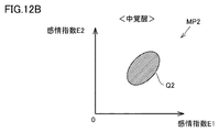
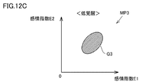
- FIG. 1 It is a flowchart which shows the emotion estimation method which concerns on embodiment. It is a figure which shows roughly the whole structure of the emotion estimation system which concerns on a modification. It is a figure for demonstrating the attachment part of the arousal degree sensor in the modification. It is a conceptual diagram (FIG. 1) of a plurality of maps in a modification. It is a conceptual diagram (FIG. 2) of a plurality of maps in a modification. It is a conceptual diagram (FIG. 3) of a plurality of maps in a modification. It is a flowchart which shows the emotion estimation method which concerns on a modification.
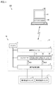
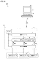
- FIG. 1 is a diagram schematically showing an overall configuration of an emotion estimation system according to an embodiment of the present disclosure.
- the emotion estimation system 100 acquires a myoelectric potential signal from the subject (subject) and estimates the emotion of the subject based on the muscle activity represented by the acquired myoelectric potential signal.
- the emotion estimation system 100 includes a wearable terminal 10 worn on the subject and a fixed terminal 90 installed in the environment around the subject. The wearable terminal 10 and the fixed terminal 90 are configured to enable bidirectional communication.
- the wearable terminal 10 includes a plurality of myoelectric potential sensors 1, a signal processing circuit 2, a controller 3, a communication module 4, and a battery 5.
- the signal processing circuit 2, the controller 3, the communication module 4, and the battery 5 are housed inside a dedicated housing 6.
- Each of the plurality of myoelectric potential sensors 1 is attached to the face of the subject and detects the myoelectric potential signal at the attachment site.
- the myoelectric potential signal means a weak electric signal generated when moving a muscle.
- the "face" of a subject is not limited to the face (front or side of the face), and the "face” may include the neck of the subject.
- a myoelectric potential sensor may be attached to the throat of the subject to detect changes in the myoelectric potential accompanying the swallowing motion of the subject.
- the plurality of myoelectric potential sensors 1 are attached to different types of muscles. The type of muscle can be identified by site.
- the plurality of myoelectric potential sensors 1 includes a first myoelectric potential sensor 11 and a second myoelectric potential sensor 12.
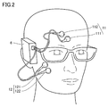
- FIG. 2 is a diagram for explaining a mounting portion of the first myoelectric potential sensor 11 and the second myoelectric potential sensor 12 in the present embodiment.
- the first myoelectric potential sensor 11 is attached to the eyebrows of the subject. More specifically, the first myoelectric potential sensor 11 includes a working electrode 111 and a reference electrode 112.
- the working electrode 111 and the reference electrode 112 are mounted directly above the corrugator supercilii.
- the mounting sites of the working electrode 111 and the reference electrode 112 may be slightly displaced from directly above the corrugator supercilii as long as they are in the vicinity of the corrugator supercilii.
- the first myoelectric potential sensor 11 detects the potential of the working electrode 111 with reference to the potential of the reference electrode 112 as the myoelectric potential of the corrugator supercilii muscle.
- the first myoelectric potential sensor 11 outputs a myoelectric potential signal indicating the activity of the corrugator supercilii muscle to the signal processing circuit 2.
- the second myoelectric potential sensor 12 is attached to the subject's cheek. More specifically, the second myoelectric potential sensor 12 includes a working electrode 121 and a reference electrode 122. The working electrode 121 and the reference electrode 122 are mounted directly above the zygomaticus major muscle. However, the mounting sites of the working electrode 121 and the reference electrode 122 may be slightly displaced from directly above the zygomaticus major muscle as long as they are in the vicinity of the zygomaticus major muscle. The second myoelectric potential sensor 12 detects the potential of the working electrode 121 based on the potential of the reference electrode 122 as the myoelectric potential of the zygomaticus major muscle. The second myoelectric potential sensor 12 outputs a myoelectric potential signal indicating the activity of the zygomaticus major muscle to the signal processing circuit 2.
- the signal processing circuit 2 includes a filter, an amplifier, an A / D converter, and the like, although none of them are shown.
- the signal processing circuit 2 performs predetermined signal processing (noise removal, rectification, amplification, digitization, etc.) on each of the myoelectric potential signals acquired by the plurality of myoelectric potential sensors 1, and processes each signal after the processing to the controller 3 Output to.
- the myoelectric potential signal from the first myoelectric potential sensor 11 processed by the signal processing circuit 2 will be referred to as “myoelectric potential signal MS1”, and the myoelectric potential signal from the second myoelectric potential sensor 12 will be referred to as the signal processing circuit 2.
- the one processed by the above is described as "myoelectric potential signal MS2".
- the controller 3 is an arithmetic unit including a processor 31 such as a CPU (Central Processing Unit), a memory 32 such as a ROM (Read Only Memory) and a RAM (Random Access Memory), and an input / output port 33.
- the controller 3 executes arithmetic processing for estimating the emotion of the subject based on the myoelectric potential signals MS1 and MS2. This arithmetic processing will be described later. Further, the controller 3 is configured to be able to exchange information with the outside (fixed terminal 90, etc.) by controlling the communication module 4.
- the communication module 4 is a communication device compliant with the short-range wireless communication standard. In response to the control by the controller 3, the communication module 4 transmits a signal indicating the calculation result of the controller 3 (a signal indicating the estimation result of the emotion of the target person) or the like to the fixed terminal 90.
- Battery 5 is a secondary battery such as a lithium ion secondary battery.
- the battery 5 supplies an operating voltage to each device in the wearable terminal 10.
- the fixed terminal 90 is, for example, a PC (Personal Computer) or a server.
- the fixed terminal 90 communicates with the wearable terminal 10 via a communication module (not shown), and receives a signal indicating the calculation result of the controller 3.
- the fixed terminal 90 includes an arithmetic unit 91 and a display device 92.
- the arithmetic unit 91 includes a processor, a memory, and an input / output port (none of which is shown), and is configured to be capable of executing various arithmetic processes.
- the display device 92 is, for example, a liquid crystal display, and displays the calculation result of the controller 3 received from the wearable terminal 10.
- the hardware configuration of the emotion estimation system 100 shown in FIG. 1 is merely an example, and is not limited to this.
- the signal processing circuit 2 and the controller 3 can be attached to the target person, and the signal processing circuit 2 and the controller 3 may be provided on the fixed terminal 90.
- the fixed terminal 90 is a stationary type, and a mobile terminal such as a smart phone may be adopted instead of the fixed terminal 90.
- the wearable terminal 10 may be provided with a small monitor for displaying the estimation result of the emotion of the target person.
- FIG. 3 is a conceptual diagram for explaining the emotion estimation method in the comparative example.
- the “emotion value Z” which is an index indicating comfort / discomfort, is calculated (see Non-Patent Document 2).
- the amount of activity of the corrugator supercilii muscle detected by the first myoelectric potential sensor 11 is represented by x
- the amount of activity of the zygomaticus major muscle detected by the second myoelectric potential sensor 12 is represented by y.
- each of the activity amounts x and y is multiplied by an appropriate coefficient, and the activity amounts after the multiplication are added together.
- the two coefficients (-0.25, 0.27) shown in the equation (1) are only examples.
- the emotion value Z represents a pleasant feeling when it is positive, and an unpleasant feeling when it is negative.
- the emotion value Z is an index capable of expressing the pleasant / unpleasant feelings in a one-dimensional manner, and is therefore useful in treating the pleasant / unpleasant feelings in a unified manner. ..
- FIG. 4 is a diagram showing an example of a myoelectric potential signal detected by each of the first myoelectric potential sensor 11 and the second myoelectric potential sensor 12.
- the horizontal axis represents the elapsed time.
- the vertical axis represents the voltage of the myoelectric potential signal MS1 of the wrinkled eyebrows muscle after the signal processing by the signal processing circuit 2 and the voltage of the myoelectric potential signal MS2 of the zygomaticus major muscle after the signal processing by the signal processing circuit 2 in this order from the top. ..
- the activity of the corrugator supercilii was detected in the time zone T1. This coincides with the timing when the target person made a mistake during play. No activity of the zygomaticus major muscle was detected during time zone T1.
- corrugator supercilii activity was detected at time zone T3. This is considered to be a signal change caused by the subject concerned about why the play did not go well. Little activity of the zygomaticus major muscle was detected during time zone T3.
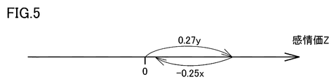
- FIG. 5 is a conceptual diagram for explaining the problem of the emotion value Z in the comparative example.
- the emotion value Z is an index that one-dimensionally expresses a pleasant / unpleasant feeling. Therefore, the negative term (-0.25x) representing the activity of the corrugator supercilii muscle and the positive term (0.27y) representing the activity of the zygomaticus major muscle can cancel each other out and become 0 (or a value close to 0). There is sex. Then, even though a plurality of emotions actually exist at the same time, it may be presumed that "I do not feel anything in particular" (when Z ⁇ 0). Alternatively, it can be presumed to be "slightly pleasant” (Z is positive but close to 0) or “slightly unpleasant” (Z is negative but close to 0). There is also sex.
- FIG. 6 is a conceptual diagram for explaining the emotion estimation method in the present embodiment.
- the amount of activity of the corrugator supercilii muscle detected by the first myoelectric potential sensor 11 is expressed as x1
- the amount of activity of the zygomaticus major muscle detected by the second myoelectric potential sensor 12 is expressed as x2.
- X1 ⁇ 0, x2 ⁇ 0 the amount of activity of the zygomaticus major muscle detected by the second myoelectric potential sensor 12
- x2 two "emotion indexes E1 and E2" are used instead of the emotion value Z.
- the emotion indexes E1 and E2 are expressed by the following determinant using four coefficients k 11 to k 22 (see equation (2)).
- Each of the coefficients k 11 to k 22 is a predetermined positive constant based on the results of prior psychological experiments. More specifically, various stimuli accompanied by emotional information are given to a certain number of subjects, and myoelectric potential signals MS1 and MS2 are acquired as responses to the stimuli. As another example, an emotion acquisition device other than the first myoelectric potential sensor 11 and the second myoelectric potential sensor 12 while giving various stimuli to a certain number of subjects and acquiring myoelectric potential signals MS1 and MS2 as responses to them. Emotional information may be acquired using (camera, heart rate sensor, sweat sensor, brain wave sensor, etc.).
- the respective coefficients k 11 to k 22 can be determined by obtaining the correspondence between the activity amount x1 of the corrugator supercilii muscle, the activity amount x2 of the zygomaticus major muscle, and emotions by using a method such as multivariate analysis.
- the formula (2) is written down, the following formula (3) is derived. From the formula (2) or the formula (3), it is understood that the emotion index E1 is calculated based on both the activity amount of the corrugator supercilii muscle x1 and the activity amount of the zygomaticus major muscle x2, and the emotion index E2 is also the corrugator supercilii muscle. It is understood that the calculation is based on both the muscle activity x1 and the zygomaticus major muscle activity x2.
- the product of the muscle activity amount x corresponding to the myoelectric potential signal and the coefficient k is calculated for each myoelectric potential signal MS1 and MS2, and the sum of the products is calculated. It may be taken (see equation (3)).
- the product is calculated by multiplying the amount of muscle activity x corresponding to the myoelectric potential signal by a predetermined coefficient in a matrix. The sum of the products may be taken (see equation (2)).
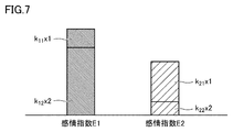
- FIG. 7 is a diagram for explaining the relationship between the emotion index E1 and the emotion index E2.
- the emotion index E1 is an index showing the strength of positive emotions.
- the emotion index E1 mainly reflects the effect of the activity amount x2 of the zygomaticus major muscle, the activity amount x1 of the corrugator supercilii muscle may also have an effect.
- the emotion index E2 is an index showing the strength of negative emotions.
- the emotion index E2 mainly reflects the effect of the activity amount x1 of the corrugator supercilii muscle, the activity amount x2 of the zygomaticus major muscle may also have an effect.
- the emotion index E1 and the emotion index E2 are not in a mutually canceling relationship, unlike the emotion value Z. Further, the emotion index E1 and the emotion index E2 are not in a trade-off relationship that when one becomes large, the other inevitably becomes small. In this sense, the emotion index E1 and the emotion index E2 are independent indexes.
- the emotion indexes E1 and E2 are calculated from the myoelectric potential signals MS1 and MS2, and the emotions of the subject are estimated based on the emotion indexes E1 and E2.
- a map as described below is used for emotion estimation from the emotion indexes E1 and E2.
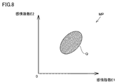
- FIG. 8 is a conceptual diagram of a map for estimating the emotion of the subject from the emotion indexes E1 and E2.
- this map MP the corresponding emotions of human beings are predetermined for each combination (E1, E2) of the emotion index E1 and the emotion index E2 based on the result of the preliminary experiment.
- the combination of the two emotion indexes (E1 and E2) is located in the region Q. Therefore, in the controller 3, when the combination of emotion indexes (E1, E2) calculated from the myoelectric potential signals MS1 and MS2 is located in the region Q, a complicated emotion in which a plurality of emotions are mixed is generated in the subject. It can be estimated that there is.
- the map MP corresponds to an example of "information" according to the present disclosure, but a table may be used instead of the map.
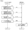
- FIG. 9 is a flowchart showing an emotion estimation method according to the present embodiment.
- the process executed by the wearable terminal 10 is shown on the left side
- the process executed by the fixed terminal 90 is shown on the right side.
- These processes are called from the main routine at a predetermined calculation cycle, and are repeatedly executed by the controller 3 of the wearable terminal 10 or the arithmetic unit 91 of the fixed terminal 90.
- Each step is realized by software processing by the controller 3 or the arithmetic unit 91, but may be realized by hardware (electric circuit) manufactured in the controller 3 or the arithmetic unit 91. In the figure, the step is described as "S".
- step 11 the controller 3 acquires the myoelectric potential signal MS1 indicating the activity of the corrugator supercilii muscle from the first myoelectric potential sensor 11. Further, in step 12, the controller 3 acquires the myoelectric potential signal MS2 indicating the activity of the zygomaticus major muscle from the second myoelectric potential sensor 12. It is preferable that these myoelectric potential signals MS1 and MS2 are acquired at the same time (or with a sufficiently short time difference).
- step 13 the controller 3 calculates two emotion indexes E1 and E2 from the two myoelectric potential signals MS1 and MS2 acquired in steps 11 and 12 according to the above equation (2) or (3).
- step 14 the controller 3 estimates the user's emotions corresponding to the emotion indexes E1 and E2 calculated in step 13 by referring to the map MP shown in FIG.
- the controller 3 controls the communication module 4 so as to transmit the data indicating the myoelectric potential signals MS1 and MS2 acquired in steps 11 and 12 to the fixed terminal 90. Further, the controller 3 causes the fixed terminal 90 to transmit the data showing the calculation results (step 13) of the emotion indexes E1 and E2 and the data showing the estimation result (step 14) of the user's emotions.
- the arithmetic unit 91 of the fixed terminal 90 receives various data from the wearable terminal 10, the arithmetic unit 91 controls the display device 92 so as to display the received data (step 19). By repeatedly executing the processes of steps 11 to 19, the emotions of the subject can be displayed on the display device 92 over time.
- FIG. 9 has described an example in which the controller 3 immediately calculates the emotion indexes E1 and E2 from the myoelectric potential signals MS1 and MS2.
- the controller 3 may execute batch processing instead of real-time processing. That is, the controller 3 stores the data of the myoelectric potential signals MS1 and MS2 in the memory 32 in time series, and later calculates the emotion indexes E1 and E2 (for example, at the timing when the operation for starting the emotion estimation is accepted). You may. Further, the controller 3 may transmit the data of the two myoelectric potential signals MS1 and MS2 to the fixed terminal 90, and calculate the emotion indexes E1 and E2 by the arithmetic unit 91 of the fixed terminal 90.
- the emotion indexes E1 and E2 are adopted instead of the emotion value Z as the index for the emotion of the subject from the two myoelectric potential signals MS1 and MS2.
- the emotion indexes E1 and E2 in the present embodiment are calculated from the determinant equation (2) or the newly written equation (3), but in these equations, the amount of activity of each muscle is only one emotion. It is expressed that the amount of activity of each muscle can contribute to multiple emotions to varying degrees.
- the emotion value Z is an index in which the contribution of the myoelectric potential signal MS1 and the contribution of the myoelectric potential signal MS2 can cancel each other, whereas the emotion indexes E1 and E2 are the contribution of the myoelectric potential signal MS1 and the myoelectric potential signal MS2. It is an index independent of each other in that the contributions of the above do not cancel each other out. Therefore, by adopting the emotion indexes E1 and E2, it becomes possible to estimate a complicated emotion in which a plurality of emotions are mixed.
- n emotion indexes using n (n is a natural number of 3 or more) myoelectric potential sensors
- muscle activity x and emotions are calculated according to the following equation (4) using a square matrix.
- the relationship with the index E can be defined.
- the number of muscle activity x and the number of emotion index E may be different.
- the matrix with the coefficient k in Eq. (4) may be an non-square matrix.
- Alertness is an index that indicates the degree of physical or cognitive arousal caused by emotions, and takes a value between excitability (high arousal) and calmness (low arousal).
- a configuration for estimating the emotion of the subject in more detail by combining the emotion indexes E1 and E2 and the alertness will be described.
- FIG. 10 is a diagram schematically showing the overall configuration of the emotion estimation system according to the modified example.
- the emotion estimation system 200 further includes an arousal sensor 7 in addition to the plurality of myoelectric potential sensors 1 (in this example, the first myoelectric potential sensor 11 and the second myoelectric potential sensor 12). It is different from the emotion estimation system 100 (see FIG. 1) according to the embodiment. Since the other configurations of the emotion estimation system 200 are similar to the corresponding configurations of the emotion estimation system 100, the description will not be repeated.
- FIG. 11 is a diagram for explaining a mounting portion of the alertness sensor 7 in the modified example.
- the alertness sensor 7 is attached, for example, to the forehead of the subject.
- the alertness sensor 7 outputs a signal for monitoring skin electrical activity on the forehead to the signal processing circuit 2.
- Skin electrical activity can include various biological activities such as skin impedance (or skin conductance, which is the reciprocal of skin impedance), or potential activity of the skin.
- the information obtained by the electrical activity of the skin is an example of "biological information" according to the present disclosure.
- the signal processed by the signal processing circuit 2 is referred to as "skin conductance signal RS".
- the controller 3 quantifies the arousal level A of the subject based on the skin conductance signal RS. More specifically, the skin conductance signal RS has a skin conductance level (SCL: Skin Conductance Level) that represents a relatively long-term level fluctuation and a skin conductance reaction (SCR: Skin) that represents a transient fluctuation on the order of several seconds. Conductance Response) is included.
- SCL Skin Conductance Level
- SCR Skin conductance reaction
- Conductance Response is included.
- the controller 3 calculates the arousal level A of the subject based on the change in SCL.
- the attachment site of the arousal sensor 7 is not limited to the forehead, and may be, for example, the temple of the subject or the palm of the subject.
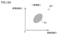
- a plurality of two-dimensional maps as described with reference to FIG. 8 are prepared for each arousal level A of the subject.
- the arousal level A is divided into three categories of high arousal, medium arousal, and low arousal, and a total of three two-dimensional maps MP1 to MP3 are provided so as to correspond to each category. Created in advance.
- the map MP1 corresponding to the high arousal level is referred to.
- the map MP2 corresponding to the medium arousal is referred to.
- the map MP3 corresponding to the low alertness is referred to. It should be noted that the arousal level A is divided into three categories only as an example, and the number of categories may be two or four or more.
- the controller 3 By preparing a plurality of maps according to the arousal level A in this way, if the arousal level A is different even if the combinations of emotion indexes (E1 and E2) are the same, the controller 3 causes the target person to express different emotions. It can be judged that it is experienced. As an example, it is possible to distinguish between the feeling of "disappointing but fun" and the feeling of the subject making and smiling.
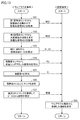
- FIG. 13 is a flowchart showing an emotion estimation method according to a modified example. With reference to FIG. 13, this flowchart further includes the process of steps 24 to 26, and includes the process of step 17 instead of the process of step 14 (see FIG. 9). Different from. The processes of steps 21 to 23 are the same as the processes of steps 11 to 13 in the embodiment, respectively.
- step 24 the controller 3 acquires the skin conductance signal RS from the alertness sensor 7.
- the acquired skin conductance signal RS is stored in the memory 32 in the controller 3 in time series.
- step 25 the controller 3 calculates the arousal level A of the subject by analyzing the skin conductance signal RS acquired in step 24 and the past skin conductance signal RS stored in the memory 32.
- step 26 the controller 3 selects a map according to the arousal level A calculated in step 25 from a plurality of maps MP1 to MP3 (see FIGS. 12A to 12C) prepared in advance.
- step 27 the controller 3 refers to the map selected in step 26 and estimates the emotion corresponding to the combination of emotion indexes (E1, E2) calculated in step 23.
- a three-dimensional map may be prepared instead.
- This three-dimensional map has an emotion index E1, an emotion index E2, and an arousal level A as the first to third axes.
- this modification it is possible to estimate a complex emotion in which a plurality of emotions are mixed, as in the embodiment. Further, according to this modification, by further introducing the arousal degree A, even if the emotion indexes E1 and E2 are the same, if the arousal degree A is different, it is distinguished from different emotions, so that the emotions of the subject can be described in more detail. It becomes possible to estimate.
- the emotion estimation method is Steps to acquire multiple myoelectric potential signals corresponding to different types of muscles in the subject's face, and A step of calculating a plurality of emotional indices based on the plurality of myoelectric potential signals, and It may include a step of estimating the emotion of the subject from the plurality of emotion indexes by using the information showing the relationship between the plurality of emotion indexes and human emotions.
- complex emotions can be estimated by using information indicating the relationship between a plurality of emotion indexes and human emotions.
- the calculation step obtains the amount of muscle activity corresponding to each of the plurality of myoelectric potential signals, and calculates the plurality of emotion indexes based on the obtained amount of activity. May include steps.
- the emotion index can be calculated with high accuracy from the amount of muscle activity.
- the calculation step is For each of the plurality of myoelectric potential signals, a step of calculating the product of the amount of muscle activity corresponding to the myoelectric potential signal and a predetermined coefficient, and It may include the step of calculating the plurality of emotional indices by taking the sum of the products for all of the plurality of myoelectric potential signals.
- the calculation step is A step of calculating the product by matrixally multiplying the amount of muscle activity corresponding to the myoelectric potential signal and a predetermined coefficient for each of the plurality of myoelectric potential signals. It may include the step of calculating the plurality of emotional indices by taking the sum of the products for all of the plurality of myoelectric potential signals.
- the emotion index can be calculated with higher accuracy from the amount of muscle activity.
- the estimation step is performed by referring to a predetermined map between the plurality of emotion indexes and the emotion of the subject. It may include the step of estimating the emotion of the subject from the emotion index.
- the emotions of the subject can be estimated with high accuracy from the plurality of emotion indexes by using a map in which the relationship between the emotions of the subject and the emotions of the subject is predetermined. ..
- the step to be acquired is The step of acquiring the myoelectric potential signal of the corrugator supercilii of the subject, and It may include the step of acquiring the myoelectric potential signal of the zygomaticus major muscle of the subject.
- the emotion estimation method described in item 6 a plurality of myoelectric potential signals can be easily acquired.
- the plurality of emotion indexes include a first emotion index that indexes positive emotions and a second emotion index that indexes negative emotions.
- the calculation step may include a step of calculating the first emotion index and the second emotion index based on the activity amount of the corrugator supercilii muscle of the subject and the activity amount of the zygomaticus major muscle of the subject. ..
- the first emotion index and the second emotion index can be calculated with high accuracy.
- the emotion estimation method further includes a step of calculating the arousal level of the subject based on the biological information of the subject.
- the emotion of the subject is estimated from the plurality of emotion indexes and the alertness by referring to the correspondence between the plurality of emotion indexes, the alertness, and the emotion of the subject. May include steps.
- the emotion estimation method may further include a step of displaying the emotion of the subject estimated by the estimation step on a display device over time.
- the emotion estimation system is Multiple myoelectric potential sensors that are arranged to correspond to different types of muscles in the subject's face and output myoelectric potential signals of the corresponding muscles, It is provided with an arithmetic unit configured to estimate the emotion of the subject based on a plurality of myoelectric potential signals from the plurality of myoelectric potential sensors.
- the arithmetic unit A plurality of emotion indexes are calculated based on the plurality of myoelectric potential signals, and a plurality of emotion indexes are calculated.
- the emotion of the subject may be estimated from the plurality of emotion indexes by using the information indicating the relationship between the plurality of emotion indexes and human emotions.
Landscapes
- Health & Medical Sciences (AREA)
- Life Sciences & Earth Sciences (AREA)
- Engineering & Computer Science (AREA)
- Animal Behavior & Ethology (AREA)
- Public Health (AREA)
- Veterinary Medicine (AREA)
- Biophysics (AREA)
- Pathology (AREA)
- Physics & Mathematics (AREA)
- Biomedical Technology (AREA)
- Heart & Thoracic Surgery (AREA)
- Medical Informatics (AREA)
- Molecular Biology (AREA)
- Surgery (AREA)
- General Health & Medical Sciences (AREA)
- Child & Adolescent Psychology (AREA)
- Psychiatry (AREA)
- Oral & Maxillofacial Surgery (AREA)
- Dermatology (AREA)
- Nuclear Medicine, Radiotherapy & Molecular Imaging (AREA)
- Radiology & Medical Imaging (AREA)
- Dentistry (AREA)
- Educational Technology (AREA)
- Physiology (AREA)
- Hospice & Palliative Care (AREA)
- Developmental Disabilities (AREA)
- Psychology (AREA)
- Social Psychology (AREA)
- Measurement Of The Respiration, Hearing Ability, Form, And Blood Characteristics Of Living Organisms (AREA)
- Measurement And Recording Of Electrical Phenomena And Electrical Characteristics Of The Living Body (AREA)
Abstract
感情推定方法は、第1~第3のステップを含む。第1のステップは、対象者の顔の筋肉のうちの異なる種類の筋肉にそれぞれ対応する複数の筋電位信号(MS1,MS2)を取得するステップである。第2のステップは、複数の筋電位信号(MS1,MS2)に基づいて複数の感情指数(E1,E2)を算出するステップである。第3のステップは、複数の感情指数(E1,E2)と人間の感情との間の関係を示す情報を用いて、複数の感情指数(E1,E2)から対象者の感情を推定するステップである。
Description
本開示は、感情推定方法および感情推定システムに関する。
心理学の分野において、人間の感情を表現するための種々のモデルが提案されている。たとえば非特許文献1には「ラッセルの円環モデル」が開示されている。ラッセルの円環モデルとは、快-不快を表す横軸と、覚醒-眠気を表す縦軸とを有する二次元平面上で、様々な感情を表せるとしたモデルである。
James A. Russell and Geraldine Pratt, "A Description of the Affective Quality Attributed to Environments", Journal of Personality and Social Psychology, 1980, Vol. 38, No. 2, 311-322
Wataru Sato, Tomomi Fujimura, Takanori Kochiyama, Naoto Suzuki, "Relationships among Facial Mimicry, Emotional Experience, and Emotion Recognition", Journal of PLoS ONE, 2013, 8(3), 1-8
対象者の顔の筋肉から筋電位信号を取得し、筋電位信号に基づいて対象者の感情を推定する技術が提案されている。
本発明者らは、人間には快/不快だけでは分類することができない、より複雑な感情が存在する点に着目した。たとえば、スポーツまたはゲーム等において熱戦の末にポイントを奪われたり敗れたりした場合などには、「悔しいながらも楽しい」との感情が生じることがある。このような複雑な感情についても対象者の顔の筋肉の筋電位信号から推定可能であることが望ましい。
本開示は、かかる課題を解決するためになされたものであり、本開示の目的は、複雑な感情を推定可能な技術を提供することである。
本開示の第1の態様に係る感情推定方法は、第1~第3のステップを含む。第1のステップは、対象者の顔の筋肉のうちの異なる種類の筋肉にそれぞれ対応する複数の筋電位信号を取得するステップである。第2のステップは、複数の筋電位信号に基づいて複数の感情指数を算出するステップである。第3のステップは、複数の感情指数と人間の感情との間の関係を示す情報を用いて、複数の感情指数から対象者の感情を推定するステップである。
本開示の第2の態様に係る感情推定システムは、複数の筋電位センサと、演算装置とを備える。複数の筋電位センサは、対象者の顔の筋肉のうちの異なる種類の筋肉にそれぞれ対応するように配置され、対応する筋肉の筋電位信号を出力する。演算装置は、複数の筋電位センサからの複数の筋電位信号に基づいて対象者の感情を推定するように構成されている。演算装置は、複数の筋電位信号に基づいて複数の感情指数を算出し、複数の感情指数と人間の感情との間の関係を示す情報を用いて、複数の感情指数から対象者の感情を推定する。
本開示によれば、複雑な感情を推定できる。
以下、本実施の形態について、図面を参照しながら詳細に説明する。なお、図中同一または相当部分には同一符号を付して、その説明は繰り返さない。
[実施の形態]
<システム構成>
図1は、本開示の実施の形態に係る感情推定システムの全体構成を概略的に示す図である。図1を参照して、感情推定システム100は、対象者(被験者)からの筋電位信号を取得し、取得した筋電位信号により表される筋肉活動に基づいて、対象者の感情を推定する。感情推定システム100は、対象者に装着されるウェアラブル端末10と、対象者の周囲の環境に設置される固定端末90とを備える。ウェアラブル端末10と固定端末90とは双方向通信が可能に構成されている。
<システム構成>
図1は、本開示の実施の形態に係る感情推定システムの全体構成を概略的に示す図である。図1を参照して、感情推定システム100は、対象者(被験者)からの筋電位信号を取得し、取得した筋電位信号により表される筋肉活動に基づいて、対象者の感情を推定する。感情推定システム100は、対象者に装着されるウェアラブル端末10と、対象者の周囲の環境に設置される固定端末90とを備える。ウェアラブル端末10と固定端末90とは双方向通信が可能に構成されている。
ウェアラブル端末10は、複数の筋電位センサ1と、信号処理回路2と、コントローラ3と、通信モジュール4と、バッテリ5とを備える。信号処理回路2とコントローラ3と通信モジュール4とバッテリ5とは、専用の筐体6の内部に収容されている。
複数の筋電位センサ1の各々は、対象者の顔に装着され、装着部位の筋電位信号を検出する。筋電位信号とは、筋肉を動かす際に発生する微弱な電気信号を意味する。本開示において、対象者の「顔」は、顔面(顔の前面または側面)に限定されず、「顔」には対象者の首が含まれ得る。たとえば、対象者の喉に筋電位センサを装着し、対象者の嚥下動作に伴う筋電位変化を検出するようにしてもよい。複数の筋電位センサ1は、互いに異なる種類の筋肉に装着される。筋肉の種類は部位によって特定され得る。筋肉の種類を特定する際、筋肉の組成または構造まで必ずしも限定しなくともよく、部位が異なれば異なる種類の筋肉として扱える。本実施の形態において、複数の筋電位センサ1は、第1筋電位センサ11と、第2筋電位センサ12とを含む。
図2は、本実施の形態における第1筋電位センサ11および第2筋電位センサ12の装着部位を説明するための図である。図2を参照して、第1筋電位センサ11は対象者の眉に装着される。より詳細には、第1筋電位センサ11は、作用電極111と、参照電極112とを含む。作用電極111および参照電極112は、皺眉筋の直上に装着される。作用電極111および参照電極112の装着部位は、皺眉筋の近傍であれば皺眉筋の直上から多少ずれてもよい。第1筋電位センサ11は、参照電極112の電位を基準とした作用電極111の電位を皺眉筋の筋電位として検出する。第1筋電位センサ11は、皺眉筋の活動を示す筋電位信号を信号処理回路2に出力する。
第2筋電位センサ12は対象者の頬に装着される。より詳細には、第2筋電位センサ12は、作用電極121と、参照電極122とを含む。作用電極121および参照電極122は、大頬骨筋の直上に装着される。ただし、作用電極121および参照電極122の装着部位は、大頬骨筋の近傍であれば大頬骨筋の直上から多少ずれてもよい。第2筋電位センサ12は、参照電極122の電位を基準とした作用電極121の電位を大頬骨筋の筋電位として検出する。第2筋電位センサ12は、大頬骨筋の活動を示す筋電位信号を信号処理回路2に出力する。
図1を再び参照して、信号処理回路2は、いずれも図示しないが、フィルタ、アンプ、A/Dコンバータなどを含む。信号処理回路2は、複数の筋電位センサ1により取得された筋電位信号の各々に所定の信号処理(ノイズ除去、整流、増幅、デジタル化など)を施し、当該処理後の各信号をコントローラ3に出力する。以下では、第1筋電位センサ11からの筋電位信号を信号処理回路2により処理したものを「筋電位信号MS1」と記載し、第2筋電位センサ12からの筋電位信号を信号処理回路2により処理したものを「筋電位信号MS2」と記載する。
コントローラ3は、CPU(Central Processing Unit)などのプロセッサ31と、ROM(Read Only Memory)およびRAM(Random Access Memory)などのメモリ32と、入出力ポート33とを含む演算装置である。コントローラ3は、筋電位信号MS1,MS2に基づいて、対象者の感情を推定するための演算処理を実行する。この演算処理については後述する。また、コントローラ3は、通信モジュール4を制御することで外部(固定端末90など)との情報の授受も可能に構成されている。
通信モジュール4は、近距離無線通信規格に準拠した通信機器である。通信モジュール4は、コントローラ3による制御に応答して、コントローラ3の演算結果を示す信号(対象者の感情の推定結果を示す信号)などを固定端末90に送信する。
バッテリ5は、リチウムイオン二次電池等の二次電池である。バッテリ5は、ウェアラブル端末10内の各機器に動作電圧を供給する。
固定端末90は、たとえばPC(Personal Computer)またはサーバである。固定端末90は、図示しない通信モジュールを介してウェアラブル端末10との間で通信を行い、コントローラ3の演算結果を示す信号を受信する。固定端末90は、演算装置91と、表示装置92とを備える。
演算装置91は、コントローラ3と同様に、プロセッサと、メモリと、入出力ポート(いずれも図示せず)とを含み、種々の演算処理を実行可能に構成されている。表示装置92は、たとえば液晶ディスプレイであって、ウェアラブル端末10から受信したコントローラ3の演算結果を表示する。
なお、図1に示した感情推定システム100のハードウェア構成は例示に過ぎず、これに限定されるものではない。たとえば、信号処理回路2とコントローラ3とが対象者に装着可能であることは必須ではなく、信号処理回路2とコントローラ3とは固定端末90に設けられていてもよい。一方で、固定端末90が定置型であることも必須ではなく、固定端末90に代えて、スマートホンなどの携帯端末を採用してもよい。また、対象者の感情の推定結果を表示するための小型モニタをウェアラブル端末10に設けてもよい。
<感情の表出>
一般に、不愉快なとき、心配事があるときなどの不快の感情は、皺眉筋の活動に表れると考えられている。一方、嬉しいとき、安心したときなどの快の感情は、大頬骨筋の活動に表れると考えられている。これらの筋肉の活動を監視することで、以下に説明する比較例のように対象者の感情を推定することも考えられる。
一般に、不愉快なとき、心配事があるときなどの不快の感情は、皺眉筋の活動に表れると考えられている。一方、嬉しいとき、安心したときなどの快の感情は、大頬骨筋の活動に表れると考えられている。これらの筋肉の活動を監視することで、以下に説明する比較例のように対象者の感情を推定することも考えられる。
図3は、比較例における感情推定方法を説明するための概念図である。図3を参照して、比較例では、快/不快を表す指標である「感情価Z」が算出される(非特許文献2参照)。第1筋電位センサ11により検出された皺眉筋の活動量をxと表し、第2筋電位センサ12により検出された大頬骨筋の活動量をyと表す。そして、下記式(1)に示すように、活動量x,yの各々に適切な係数を乗算し、当該乗算後の活動量同士を足し合わせる。なお、式(1)に示された2つの係数(-0.25,0.27)は一例に過ぎない。

感情価Zは、正の場合には快の感情を表し、負の場合には不快の感情を表す。式(1)から理解されるように、感情価Zは、快/不快の感情を一次元的に表すことができる指標であるため、快/不快の感情を統一的に扱う上で有益である。
その一方で、人間には、快/不快だけでは分類することができない、より複雑な感情が存在する。以下では、この感情について、運動中(この例では卓球のプレイ中)の対象者から取得された筋電位信号MS1,MS2を例に説明する。
図4は、第1筋電位センサ11および第2筋電位センサ12の各々により検出された筋電位信号の一例を示す図である。横軸は経過時間を表す。縦軸は、上から順に、信号処理回路2による信号処理後の皺眉筋の筋電位信号MS1の電圧と、信号処理回路2による信号処理後の大頬骨筋の筋電位信号MS2の電圧とを表す。電圧の振れ幅が大きいほど筋肉の活動が大きい。
図4を参照して、まず、時間帯T1において皺眉筋の活動が検出された。これは、対象者がプレイ中にミスしたタイミングと一致する。時間帯T1には大頬骨筋の活動は検出されなかった。
また、時間帯T2において大頬骨筋の活動が検出された。この電圧変化は、対戦相手と交わした会話を対象者が楽しんだことによるものである。時間帯T2には皺眉筋の活動は検出されなかった。
さらに、時間帯T3において皺眉筋の活動が検出された。これは、プレイがうまくいかないのはなぜなのかと対象者が悩んだことに起因する信号変化と考えられる。時間帯T3には大頬骨筋の活動は、ほとんど検出されなかった。
その後、時間帯T4において、皺眉筋の活動と大頬骨筋の活動とが同時に検出された。このときにどのように感じていたか対象者に聞き取り調査を行ったところ、「プレイが楽しくて笑顔になったが、そのプレイ中にミスが出て悔しい思いをした」との回答であった。このように、人間には、複数の感情が混在した複雑な感情が湧くことがある。
また、他の例として、人間は、考え事をしていたり心配事があったりする場合に、眉間に皺が寄った状態で口がまっすぐに横に伸びた表情を取り、皺眉筋の活動と大頬骨筋の活動とが同時に検出されることがある。このような感情も単なる快/不快とは異なる複雑な感情である。しかしながら、以下に説明するように、比較例では、そのような複雑な感情を推定することはできない。
図5は、比較例における感情価Zの課題を説明するための概念図である。図5を参照して、上記式(1)にて説明したように、感情価Zは、快/不快の感情を一次元的に表す指標である。そのため、皺眉筋の活動を表す負の項(-0.25x)と大頬骨筋の活動を表す正の項(0.27y)とが互いに打ち消し合って0(または0に近い値)となる可能性がある。そうすると、実際には複数の感情が同時に存在しているにも拘らず、「特に何も感じていない」(Z≒0の場合)と推定される可能性がある。あるいは、「やや快に感じた」(Zが正だが、0に近い場合)と推定されたり、「わずかに不快に感じた」(Zが負だが、0に近い場合)と推定されたりする可能性もある。
感情価Zでは快と不快とが単一軸の両極に配置されている。これには、快と不快とが対極をなしており、人間が快と不快とを同時に経験することはないとの暗黙の前提が存在する。そのため、比較例では、複数の感情が混ざり合った複雑な感情を推定できない。
図6は、本実施の形態における感情推定方法を説明するための概念図である。図6を参照して、以下では、第1筋電位センサ11により検出された皺眉筋の活動量をx1と表し、第2筋電位センサ12により検出された大頬骨筋の活動量をx2と表す(x1≧0,x2≧0)。本実施の形態では、感情価Zに代えて、2つの「感情指数E1,E2」が用いられる。感情指数E1,E2は、4つの係数k11~k22を用いて以下の行列式で表現される(式(2)参照)。

係数k11~k22の各々は、事前の心理学的な実験の結果に基づいて予め定められた正の定数である。より具体的には、感情情報を伴う様々な刺激を一定数の被験者に与え、それに対する反応としての筋電位信号MS1,MS2を取得する。他の例として、様々な刺激を一定数の被験者に与え、それに対する反応としての筋電位信号MS1,MS2を取得しつつ、第1筋電位センサ11および第2筋電位センサ12以外の感情取得装置(カメラ、心拍センサ、汗センサ、脳波センサなど)を用いて感情情報を取得してもよい。そして、皺眉筋の活動量x1と大頬骨筋の活動量x2と感情との間の対応関係を多変量解析等の手法を用いて求めることにより、各係数k11~k22を決定できる。
なお、式(2)を書き下すと、下記式(3)が導出される。式(2)または式(3)より、感情指数E1が皺眉筋の活動量x1と大頬骨筋の活動量x2との両方に基づいて算出されることが理解されるとともに、感情指数E2も皺眉筋の活動量x1と大頬骨筋の活動量x2との両方に基づいて算出されることが理解される。

このように、感情指数E1,ESの算出においては、筋電位信号MS1,MS2毎に、その筋電位信号に対応する筋肉の活動量xと係数kとの積を算出し、その積の総和を取ってもよい(式(3)参照)。あるいは、筋電位信号MS1,MS2毎に、前記複数の筋電位信号毎に、その筋電位信号に対応する筋肉の活動量xと所定の係数とを行列的に掛け合わせることで積を算出し、その積の総和を取ってもよい(式(2)参照)。
図7は、感情指数E1と感情指数E2との間の関係を説明するための図である。図7を参照して、本実施の形態において、感情指数E1は、肯定的(ポジティブ)な感情の強さを表す指標である。感情指数E1には、主に大頬骨筋の活動量x2の影響が反映されるものの、皺眉筋の活動量x1も影響を与え得る。一方、感情指数E2は、否定的(ネガティブ)な感情の強さを表す指標である。感情指数E2には、主に皺眉筋の活動量x1の影響が反映されるものの、大頬骨筋の活動量x2も影響を与え得る。
感情指数E1と感情指数E2とは、感情価Zとは異なり、互いに相殺し合う関係にはない。また、感情指数E1と感情指数E2とは、一方が大きくなると他方が必然的に小さくなるとのトレードオフの関係にもない。この意味で、感情指数E1と感情指数E2とは、互いに独立した指標である。
本実施の形態では、まず、筋電位信号MS1,MS2から感情指数E1,E2が算出され、さらに感情指数E1,E2に基づいて対象者の感情が推定される。感情指数E1,E2からの感情推定には、以下に説明するようなマップが用いられる。
図8は、感情指数E1,E2から対象者の感情を推定するためのマップの概念図である。図8を参照して、このマップMPにおいては、事前実験の結果に基づき、感情指数E1と感情指数E2との組合せ(E1,E2)毎に、人間の対応する感情が予め定められている。2つの感情が混在した複雑な感情が対象者に生じている場合、2つの感情指数の組合せ(E1,E2)が領域Q内に位置することとなる。よって、コントローラ3は、筋電位信号MS1,MS2から算出された感情指数の組合せ(E1,E2)が領域Q内に位置する場合に、複数の感情が混在した複雑な感情が対象者に生じていると推定できる。なお、マップMPは、本開示に係る「情報」の一例に相当するが、マップに代えてテーブルを用いてもよい。
<処理フロー>
図9は、本実施の形態に係る感情推定方法を示すフローチャートである。図9および後述する図13に示すフローチャートでは、左側にウェアラブル端末10により実行される処理を図示し、右側に固定端末90により実行される処理を図示している。これらの処理は、所定の演算周期でメインルーチンから呼び出され、ウェアラブル端末10のコントローラ3または固定端末90の演算装置91により繰り返し実行される。各ステップは、コントローラ3または演算装置91によるソフトウェア処理によって実現されるが、コントローラ3または演算装置91内に作製されたハードウェア(電気回路)によって実現されてもよい。なお、図中ではステップを「S」と記載する。
図9は、本実施の形態に係る感情推定方法を示すフローチャートである。図9および後述する図13に示すフローチャートでは、左側にウェアラブル端末10により実行される処理を図示し、右側に固定端末90により実行される処理を図示している。これらの処理は、所定の演算周期でメインルーチンから呼び出され、ウェアラブル端末10のコントローラ3または固定端末90の演算装置91により繰り返し実行される。各ステップは、コントローラ3または演算装置91によるソフトウェア処理によって実現されるが、コントローラ3または演算装置91内に作製されたハードウェア(電気回路)によって実現されてもよい。なお、図中ではステップを「S」と記載する。
ステップ11において、コントローラ3は、第1筋電位センサ11から皺眉筋の活動を示す筋電位信号MS1を取得する。また、ステップ12において、コントローラ3は、第2筋電位センサ12から大頬骨筋の活動を示す筋電位信号MS2を取得する。これらの筋電位信号MS1,MS2は同時に(あるいは十分に短い時間差で)取得されたものであることが好ましい。
ステップ13において、コントローラ3は、上記式(2)または式(3)に従って、ステップ11,12にて取得された2つの筋電位信号MS1,MS2から2つの感情指数E1,E2を算出する。
ステップ14において、コントローラ3は、図8に示したマップMPを参照することによって、ステップ13にて算出した感情指数E1,E2に対応するユーザの感情を推定する。
コントローラ3は、ステップ11,12にて取得した筋電位信号MS1,MS2を示すデータを固定端末90に送信するように通信モジュール4を制御する。また、コントローラ3は、感情指数E1,E2の算出結果(ステップ13)を示すデータと、ユーザの感情の推定結果(ステップ14)を示すデータとついても固定端末90に送信させる。固定端末90の演算装置91は、ウェアラブル端末10から各種データを受信すると、受信したデータを表示するように表示装置92を制御する(ステップ19)。ステップ11~19の処理を繰り返し実行することにより、対象者の感情を表示装置92に経時的に表示できる。
なお、図9では、コントローラ3が筋電位信号MS1,MS2から感情指数E1,E2を即時に算出する例について説明した。しかし、コントローラ3は、リアルタイム処理に代えてバッチ処理を実行してもよい。すなわち、コントローラ3は、筋電位信号MS1,MS2のデータをメモリ32に時系列に格納しておき、後に(たとえば感情推定を開始するための操作を受け付けたタイミングで)感情指数E1,E2を算出してもよい。また、コントローラ3は、2つの筋電位信号MS1,MS2のデータを固定端末90に送信し、固定端末90の演算装置91によって感情指数E1,E2を算出してもよい。
以上のように、本実施の形態においては、2つの筋電位信号MS1,MS2から対象者の感情するための指標として、感情価Zに代えて感情指数E1,E2が採用される。本実施の形態における感情指数E1,E2は、行列式である式(2)またはその書き下しである式(3)から算出されるが、これらの式では、各筋肉の活動量が1つの感情のみに寄与するのではなく、各筋肉の活動量が程度の差はあっても複数の感情に対して寄与し得ることが表現されている。また、感情価Zが筋電位信号MS1の寄与と筋電位信号MS2の寄与とが相殺し得る指標であるのに対して、感情指数E1,E2は、筋電位信号MS1の寄与と筋電位信号MS2の寄与とが相殺し合わない点において、互いに独立した指標である。よって、感情指数E1,E2の採用により、複数の感情が混在した複雑な感情を推定することが可能になる。
本実施の形態では、2つの筋電位センサを対象者の顔に装着する例について説明した。しかし、筋電位センサの装着数は2つに限定されず、3つ以上の筋電位センサを対象者の顔に装着してもよい。たとえば、n(nは3以上の自然数)個の筋電位センサを用いてn個の感情指数を算出する場合には、正方行列を用いた下記式(4)に従って、筋肉の活動量xと感情指数Eとの間の関係を規定できる。

また、筋肉の活動量xの数と感情指数Eの数とが異なってもよい。その場合には式(4)において係数kの行列を非正方行列とすればよい。
[変形例]
対象者に生じる感情は、対象者の覚醒度によっても影響され得る。覚醒度とは、感情が引き起こす身体的または認知的な喚起の程度を示す指標であり、興奮性(高覚醒)と沈静性(低覚醒)との間の値を取る。この変形例においては、感情指数E1,E2と覚醒度とを組み合わせることによって、対象者の感情をより詳細に推定する構成について説明する。
対象者に生じる感情は、対象者の覚醒度によっても影響され得る。覚醒度とは、感情が引き起こす身体的または認知的な喚起の程度を示す指標であり、興奮性(高覚醒)と沈静性(低覚醒)との間の値を取る。この変形例においては、感情指数E1,E2と覚醒度とを組み合わせることによって、対象者の感情をより詳細に推定する構成について説明する。
図10は、変形例に係る感情推定システムの全体構成を概略的に示す図である。図10を参照して、感情推定システム200は、複数の筋電位センサ1(この例では第1筋電位センサ11および第2筋電位センサ12)に加えて覚醒度センサ7をさらに備える点において、実施の形態に係る感情推定システム100(図1参照)と異なる。感情推定システム200の他の構成は、感情推定システム100の対応する構成と同様であるため、説明は繰り返さない。
図11は、変形例における覚醒度センサ7の装着部位を説明するための図である。図11を参照して、覚醒度センサ7は、たとえば対象者の額に装着される。覚醒度センサ7は、額における皮膚電気活動を監視するための信号を信号処理回路2に出力する。皮膚電気活動には、皮膚インピーダンス(もしくは皮膚インピーダンス逆数である皮膚コンダクタンス)、または、皮膚の電位活動などの様々な生体活動が含まれ得る。なお、皮膚電気活動による情報は、本開示に係る「生体情報」の一例である。
以下では、皮膚電気活動のうち皮膚コンダクタンスを取得する例について説明する。信号処理回路2により処理された信号を「皮膚コンダクタンス信号RS」と称する。コントローラ3は、皮膚コンダクタンス信号RSに基づいて、対象者の覚醒度Aを定量化する。より具体的には、皮膚コンダクタンス信号RSは、比較的長時間のレベル変動を表す皮膚コンダクタンスレベル(SCL:Skin Conductance Level)と、数秒オーダの一過性の変動を表す皮膚コンダクタンス反応(SCR:Skin Conductance Response)とを含む。コントローラ3は、SCLの変化に基づいて対象者の覚醒度Aを算出する。なお、覚醒度センサ7の装着部位は額に限定されず、たとえば、対象者のこめかみであってもよいし、対象者の手のひらであってもよい。本実施の形態では、図8にて説明したような2次元マップが対象者の覚醒度A毎に複数準備される。
図12A~図12Cは、変形例における複数のマップの概念図である。図12A~図12Cを参照して、変形例では、高覚醒、中覚醒および低覚醒の3つの区分に覚醒度Aを分け、各区分に対応するように合計3つの2次元マップMP1~MP3が事前に作成される。対象者の覚醒度Aが高い区分に属する場合、高覚醒に対応するマップMP1が参照される。対象者の覚醒度Aが中程度の区分に属する場合、中覚醒に対応するマップMP2が参照される。対象者の覚醒度Aが低い区分に属する場合、低覚醒に対応するマップMP3が参照される。なお、ここで覚醒度Aを3つの区分に分けたのは一例に過ぎず、区分数は2つであってもよいし4つ以上であってもよい。
このように覚醒度Aに応じた複数のマップを準備することにより、感情指数の組合せ(E1,E2)が等しくても覚醒度Aが異なる場合には、コントローラ3は、対象者が異なる感情を経験していると判断できる。一例として、「悔しいが楽しい」との感情と、対象者が作り笑顔を見せているときの感情とを区別することが可能となる。
図13は、変形例に係る感情推定方法を示すフローチャートである。図13を参照して、このフローチャートは、ステップ24~26の処理をさらに含む点と、ステップ14の処理に代えてステップ17の処理を含む点とにおいて、実施の形態におけるフローチャート(図9参照)と異なる。ステップ21~23の処理は、実施の形態におけるステップ11~13の処理とそれぞれ同様である。
ステップ24において、コントローラ3は、覚醒度センサ7から皮膚コンダクタンス信号RSを取得する。取得された皮膚コンダクタンス信号RSは、コントローラ3内のメモリ32に時系列に格納される。
ステップ25において、コントローラ3は、ステップ24にて取得された皮膚コンダクタンス信号RSと、メモリ32に格納された過去の皮膚コンダクタンス信号RSとを解析することによって、対象者の覚醒度Aを算出する。
ステップ26において、コントローラ3は、予め準備された複数のマップMP1~MP3(図12A~図12C参照)の中からステップ25にて算出された覚醒度Aに応じたマップを選択する。
ステップ27において、コントローラ3は、ステップ26にて選択されたマップを参照して、ステップ23にて算出された感情指数の組合せ(E1,E2)に対応する感情を推定する。
なお、この変形例では、複数の2次元マップが準備されると説明したが、これに代えて3次元マップを準備してもよい。この3次元マップは、第1軸~第3軸として、感情指数E1と感情指数E2と覚醒度Aとを有する。このような3次元マップを参照することによっても感情指数E1,E2と覚醒度Aとの組み合わせに応じて対象者の感情を推定することが可能である。
以上のように、本変形例によれば、実施の形態と同様に、複数の感情が混在した複雑な感情を推定できる。さらに、本変形例によれば、覚醒度Aをさらに導入することによって、感情指数E1,E2が等しくても覚醒度Aが異なれば異なる感情と区別されるので、より詳細に対象者の感情を推定することが可能となる。
<態様>
上述した複数の例示的な実施形態は、以下の態様の具体例であることが当業者により理解される。
上述した複数の例示的な実施形態は、以下の態様の具体例であることが当業者により理解される。
(第1項)
第1の態様に係る感情推定方法は、
対象者の顔の筋肉のうちの異なる種類の筋肉にそれぞれ対応する複数の筋電位信号を取得するステップと、
前記複数の筋電位信号に基づいて複数の感情指数を算出するステップと、
前記複数の感情指数と人間の感情との間の関係を示す情報を用いて、前記複数の感情指数から前記対象者の感情を推定するステップとを含んでもよい。
第1の態様に係る感情推定方法は、
対象者の顔の筋肉のうちの異なる種類の筋肉にそれぞれ対応する複数の筋電位信号を取得するステップと、
前記複数の筋電位信号に基づいて複数の感情指数を算出するステップと、
前記複数の感情指数と人間の感情との間の関係を示す情報を用いて、前記複数の感情指数から前記対象者の感情を推定するステップとを含んでもよい。
第1項に記載の感情推定方法によれば、複数の感情指数と人間の感情との間の関係を示す情報を用いることで、複雑な感情を推定できる。
(第2項)
第1項に記載の感情推定方法において、前記算出するステップは、前記複数の筋電位信号の各々に対応する筋肉の活動量を求め、求めた活動量に基づいて前記複数の感情指数を算出するステップを含み得る。
第1項に記載の感情推定方法において、前記算出するステップは、前記複数の筋電位信号の各々に対応する筋肉の活動量を求め、求めた活動量に基づいて前記複数の感情指数を算出するステップを含み得る。
第2項に記載の感情推定方法によれば、筋肉の活動量から感情指数を高精度に算出できる。
(第3項)
第2項に記載の感情推定方法において、前記算出するステップは、
前記複数の筋電位信号毎に、その筋電位信号に対応する筋肉の活動量と所定の係数との積を算出するステップと、
前記複数の筋電位信号のすべてについて前記積の総和を取ることによって、前記複数の感情指数を算出するステップとを含み得る。
第2項に記載の感情推定方法において、前記算出するステップは、
前記複数の筋電位信号毎に、その筋電位信号に対応する筋肉の活動量と所定の係数との積を算出するステップと、
前記複数の筋電位信号のすべてについて前記積の総和を取ることによって、前記複数の感情指数を算出するステップとを含み得る。
(第4項)
第2項に記載の感情推定方法において、前記算出するステップは、
前記複数の筋電位信号毎に、その筋電位信号に対応する筋肉の活動量と所定の係数とを行列的に掛け合わせることで積を算出するステップと、
前記複数の筋電位信号のすべてについて前記積の総和を取ることによって、前記複数の感情指数を算出するステップとを含み得る。
第2項に記載の感情推定方法において、前記算出するステップは、
前記複数の筋電位信号毎に、その筋電位信号に対応する筋肉の活動量と所定の係数とを行列的に掛け合わせることで積を算出するステップと、
前記複数の筋電位信号のすべてについて前記積の総和を取ることによって、前記複数の感情指数を算出するステップとを含み得る。
第3項または第4項に記載の感情推定方法によれば、筋肉の活動量から感情指数をより高精度に算出できる。
(第5項)
第1項~第4項に記載の感情推定方法において、前記推定するステップは、前記複数の感情指数と前記対象者の感情との間で予め定められたマップを参照することによって、前記複数の感情指数から前記対象者の感情を推定するステップを含み得る。
第1項~第4項に記載の感情推定方法において、前記推定するステップは、前記複数の感情指数と前記対象者の感情との間で予め定められたマップを参照することによって、前記複数の感情指数から前記対象者の感情を推定するステップを含み得る。
第5項に記載の感情推定方法によれば、複数の感情指数と対象者の感情の関係が予め定められたマップを用いることで、複数の感情指数から対象者の感情を高精度に推定できる。
(第6項)
第1項~第5項に記載の感情推定方法において、前記取得するステップは、
前記対象者の皺眉筋の筋電位信号を取得するステップと、
前記対象者の大頬骨筋の筋電位信号を取得するステップとを含み得る。
第1項~第5項に記載の感情推定方法において、前記取得するステップは、
前記対象者の皺眉筋の筋電位信号を取得するステップと、
前記対象者の大頬骨筋の筋電位信号を取得するステップとを含み得る。
第6項に記載の感情推定方法によれば、複数の筋電位信号を容易に取得できる。
(第7項)
第6項に記載の感情推定方法において、前記複数の感情指数は、肯定的な感情を指標する第1感情指数と、否定的な感情を指標する第2感情指数とを含み、
前記算出するステップは、前記対象者の皺眉筋の活動量と前記対象者の大頬骨筋の活動量とに基づいて、前記第1感情指数と前記第2感情指数とを算出するステップを含み得る。
(第7項)
第6項に記載の感情推定方法において、前記複数の感情指数は、肯定的な感情を指標する第1感情指数と、否定的な感情を指標する第2感情指数とを含み、
前記算出するステップは、前記対象者の皺眉筋の活動量と前記対象者の大頬骨筋の活動量とに基づいて、前記第1感情指数と前記第2感情指数とを算出するステップを含み得る。
第7項に記載の感情推定方法によれば、第1感情指数と第2感情指数とを高精度に算出できる。
(第8項)
第1項~第7項に記載の感情推定方法において、前記対象者の生体情報に基づいて前記対象者の覚醒度を算出するステップをさらに含み、
前記推定するステップは、前記複数の感情指数と前記覚醒度と前記対象者の感情との対応関係を参照することによって、前記複数の感情指数と前記覚醒度とから前記対象者の感情を推定するステップを含み得る。
第1項~第7項に記載の感情推定方法において、前記対象者の生体情報に基づいて前記対象者の覚醒度を算出するステップをさらに含み、
前記推定するステップは、前記複数の感情指数と前記覚醒度と前記対象者の感情との対応関係を参照することによって、前記複数の感情指数と前記覚醒度とから前記対象者の感情を推定するステップを含み得る。
第8項に記載の感情推定方法によれば、感情指数の組合せが等しくても覚醒度が異なる場合には、対象者が異なる感情を経験していると判断できる。
(請求項9)
第1項~第8項に記載の感情推定方法において、前記推定するステップにより推定した前記対象者の感情を表示装置に経時的に表示するステップをさらに含み得る。
第1項~第8項に記載の感情推定方法において、前記推定するステップにより推定した前記対象者の感情を表示装置に経時的に表示するステップをさらに含み得る。
第9項に記載の感情推定方法によれば、対象者の感情の経時変化を容易に観察できる。
(第10項)
第1の態様に係る感情推定システムは、
対象者の顔の筋肉のうちの異なる種類の筋肉にそれぞれ対応するように配置され、対応する筋肉の筋電位信号を出力する複数の筋電位センサと、
前記複数の筋電位センサからの複数の筋電位信号に基づいて前記対象者の感情を推定するように構成された演算装置とを備え、
前記演算装置は、
前記複数の筋電位信号に基づいて複数の感情指数を算出し、
前記複数の感情指数と人間の感情との間の関係を示す情報を用いて、前記複数の感情指数から前記対象者の感情を推定してもよい。
(第10項)
第1の態様に係る感情推定システムは、
対象者の顔の筋肉のうちの異なる種類の筋肉にそれぞれ対応するように配置され、対応する筋肉の筋電位信号を出力する複数の筋電位センサと、
前記複数の筋電位センサからの複数の筋電位信号に基づいて前記対象者の感情を推定するように構成された演算装置とを備え、
前記演算装置は、
前記複数の筋電位信号に基づいて複数の感情指数を算出し、
前記複数の感情指数と人間の感情との間の関係を示す情報を用いて、前記複数の感情指数から前記対象者の感情を推定してもよい。
第10項に記載の感情推定システムによれば、第1項に記載の感情推定方法と同様に、複雑な感情を推定できる。
今回開示された実施の形態は、すべての点で例示であって制限的なものではないと考えられるべきである。本開示の範囲は、上記した実施の形態の説明ではなくて請求の範囲によって示され、請求の範囲と均等の意味および範囲内でのすべての変更が含まれることが意図される。
1 複数の筋電位センサ、11 第1筋電位センサ、12 第2筋電位センサ、111,121 作用電極、112,122 参照電極、2 信号処理回路、3 コントローラ、31 CPU、32 メモリ、33 入出力ポート、4 通信モジュール、5 バッテリ、6 筐体、7 覚醒度センサ、10 ウェアラブル端末、90 固定端末、91 演算装置、92 表示装置、100,200 感情推定システム。
Claims (10)
- 対象者の顔の筋肉のうちの異なる種類の筋肉にそれぞれ対応する複数の筋電位信号を取得するステップと、
前記複数の筋電位信号に基づいて複数の感情指数を算出するステップと、
前記複数の感情指数と人間の感情との間の関係を示す情報を用いて、前記複数の感情指数から前記対象者の感情を推定するステップとを含む、感情推定方法。 - 前記算出するステップは、前記複数の筋電位信号の各々に対応する筋肉の活動量を求め、求めた活動量に基づいて前記複数の感情指数を算出するステップを含む、請求項1に記載の感情推定方法。
- 前記算出するステップは、
前記複数の筋電位信号毎に、その筋電位信号に対応する筋肉の活動量と所定の係数との積を算出するステップと、
前記複数の筋電位信号のすべてについて前記積の総和を取ることによって、前記複数の感情指数を算出するステップとを含む、請求項2に記載の感情推定方法。 - 前記算出するステップは、
前記複数の筋電位信号毎に、その筋電位信号に対応する筋肉の活動量と所定の係数とを行列的に掛け合わせることで積を算出するステップと、
前記複数の筋電位信号のすべてについて前記積の総和を取ることによって、前記複数の感情指数を算出するステップとを含む、請求項2に記載の感情推定方法。 - 前記推定するステップは、前記複数の感情指数と前記対象者の感情との間で予め定められたマップを参照することによって、前記複数の感情指数から前記対象者の感情を推定するステップを含む、請求項1に記載の感情推定方法。
- 前記取得するステップは、
前記対象者の皺眉筋の筋電位信号を取得するステップと、
前記対象者の大頬骨筋の筋電位信号を取得するステップとを含む、請求項1に記載の感情推定方法。 - 前記複数の感情指数は、肯定的な感情を指標する第1感情指数と、否定的な感情を指標する第2感情指数とを含み、
前記算出するステップは、前記対象者の皺眉筋の活動量と前記対象者の大頬骨筋の活動量とに基づいて、前記第1感情指数と前記第2感情指数とを算出するステップを含む、請求項6に記載の感情推定方法。 - 前記対象者の生体情報に基づいて前記対象者の覚醒度を算出するステップをさらに含み、
前記推定するステップは、前記複数の感情指数と前記覚醒度と前記対象者の感情との対応関係を参照することによって、前記複数の感情指数と前記覚醒度とから前記対象者の感情を推定するステップを含む、請求項1に記載の感情推定方法。 - 前記推定するステップにより推定した前記対象者の感情を表示装置に経時的に表示するステップをさらに含む、請求項1に記載の感情推定方法。
- 対象者の顔の筋肉のうちの異なる種類の筋肉にそれぞれ対応するように配置され、対応する筋肉の筋電位信号を出力する複数の筋電位センサと、
前記複数の筋電位センサからの複数の筋電位信号に基づいて前記対象者の感情を推定するように構成された演算装置とを備え、
前記演算装置は、
前記複数の筋電位信号に基づいて複数の感情指数を算出し、
前記複数の感情指数と人間の感情との間の関係を示す情報を用いて、前記複数の感情指数から前記対象者の感情を推定する、感情推定システム。
Priority Applications (1)
| Application Number | Priority Date | Filing Date | Title |
|---|---|---|---|
| JP2021553450A JP7311118B2 (ja) | 2019-10-30 | 2020-10-20 | 感情推定方法および感情推定システム |
Applications Claiming Priority (2)
| Application Number | Priority Date | Filing Date | Title |
|---|---|---|---|
| JP2019-197330 | 2019-10-30 | ||
| JP2019197330 | 2019-10-30 |
Publications (1)
| Publication Number | Publication Date |
|---|---|
| WO2021085231A1 true WO2021085231A1 (ja) | 2021-05-06 |
Family
ID=75715979
Family Applications (1)
| Application Number | Title | Priority Date | Filing Date |
|---|---|---|---|
| PCT/JP2020/039356 Ceased WO2021085231A1 (ja) | 2019-10-30 | 2020-10-20 | 感情推定方法および感情推定システム |
Country Status (2)
| Country | Link |
|---|---|
| JP (1) | JP7311118B2 (ja) |
| WO (1) | WO2021085231A1 (ja) |
Cited By (2)
| Publication number | Priority date | Publication date | Assignee | Title |
|---|---|---|---|---|
| WO2023037749A1 (ja) * | 2021-09-07 | 2023-03-16 | 株式会社島津製作所 | 評価方法、評価システム、およびプログラム |
| WO2023223832A1 (ja) * | 2022-05-18 | 2023-11-23 | 株式会社資生堂 | 評価装置、評価方法、および美容方法 |
Citations (2)
| Publication number | Priority date | Publication date | Assignee | Title |
|---|---|---|---|---|
| US20030032890A1 (en) * | 2001-07-12 | 2003-02-13 | Hazlett Richard L. | Continuous emotional response analysis with facial EMG |
| US8401248B1 (en) * | 2008-12-30 | 2013-03-19 | Videomining Corporation | Method and system for measuring emotional and attentional response to dynamic digital media content |
-
2020
- 2020-10-20 JP JP2021553450A patent/JP7311118B2/ja active Active
- 2020-10-20 WO PCT/JP2020/039356 patent/WO2021085231A1/ja not_active Ceased
Patent Citations (2)
| Publication number | Priority date | Publication date | Assignee | Title |
|---|---|---|---|---|
| US20030032890A1 (en) * | 2001-07-12 | 2003-02-13 | Hazlett Richard L. | Continuous emotional response analysis with facial EMG |
| US8401248B1 (en) * | 2008-12-30 | 2013-03-19 | Videomining Corporation | Method and system for measuring emotional and attentional response to dynamic digital media content |
Non-Patent Citations (2)
| Title |
|---|
| FUJIMURA, TOMOMI: "Facial elctromyographic activities to dynamic and static facial expressions", IEICE TECHNICAL REPORT, vol. 1 08, no. 317, 2008, pages 23 - 28, ISSN: 0913-5685 * |
| OHIRA, HIDEKI: "Facial Electromyograph as a Measure of Emotional Expression", BULLETIN OF TOKAI WOMEN'S UNIVERSITY, 1992, pages 259 - 272, XP055822009, ISSN: 0287-0525, Retrieved from the Internet <URL:https://tokaigakuin-u.repo.nii.ac.jp/?action=repository_action_common_download&item_id=2258&item_no=1&attribute_id=21&file_no=1> [retrieved on 20201104] * |
Cited By (5)
| Publication number | Priority date | Publication date | Assignee | Title |
|---|---|---|---|---|
| WO2023037749A1 (ja) * | 2021-09-07 | 2023-03-16 | 株式会社島津製作所 | 評価方法、評価システム、およびプログラム |
| JPWO2023037749A1 (ja) * | 2021-09-07 | 2023-03-16 | ||
| JP7697518B2 (ja) | 2021-09-07 | 2025-06-24 | 株式会社島津製作所 | 評価方法、評価システム、およびプログラム |
| US12688730B2 (en) | 2021-09-07 | 2026-07-21 | Shimadzu Corporation | Method, system, and program for facial expression evaluation using reference and measurement result |
| WO2023223832A1 (ja) * | 2022-05-18 | 2023-11-23 | 株式会社資生堂 | 評価装置、評価方法、および美容方法 |
Also Published As
| Publication number | Publication date |
|---|---|
| JPWO2021085231A1 (ja) | 2021-05-06 |
| JP7311118B2 (ja) | 2023-07-19 |
Similar Documents
| Publication | Publication Date | Title |
|---|---|---|
| Dzedzickis et al. | Human emotion recognition: Review of sensors and methods | |
| US20220156995A1 (en) | Augmented reality systems and methods utilizing reflections | |
| KR102425479B1 (ko) | 사용자의 정보로 아바타를 생성하여 외부의 메타버스플랫폼에 제공하고 사용자 맞춤형 디지털치료제를 추천하는 시스템 및 방법 | |
| US10430985B2 (en) | Augmented reality systems and methods utilizing reflections | |
| KR102432248B1 (ko) | 아바타를 생성하여 외부의 메타버스플랫폼에 제공하여 아바타를 업데이트하고, 업데이트된 아바타에 대한 nft를 제공하는 시스템 및 방법 | |
| Nacke | An introduction to physiological player metrics for evaluating games | |
| KR102453304B1 (ko) | 치매 예방 및 자가진단을 위한 가상현실콘텐츠를 제공하는 시스템 | |
| US20150025335A1 (en) | Method and system for monitoring pain of patients | |
| KR102445134B1 (ko) | 사용자의 정보를 기반으로 아바타를 생성하고, 아바타에 대한 nft를 제공하는 시스템 및 방법 | |
| KR102445133B1 (ko) | 아바타를 생성하여 외부의 메타버스플랫폼에 제공하고 아바타를 업데이트하는 시스템 및 방법 | |
| Welch | Physiological signals of autistic children can be useful | |
| KR102425481B1 (ko) | 재활치료를 위한 가상현실 커뮤니케이션 시스템 | |
| KR102429630B1 (ko) | 헬스케어를 위한 커뮤니케이션 npc아바타를 생성하는 시스템 | |
| KR102429627B1 (ko) | 가상현실에서 아바타를 생성하고 복수의 콘텐츠를 제공하는 시스템 | |
| KR102437583B1 (ko) | 생체신호를 활용한 선호 색상에 대한 사용자 맞춤형 색상콘텐츠를 제공하는 시스템 및 방법 | |
| JP7311118B2 (ja) | 感情推定方法および感情推定システム | |
| KR102617431B1 (ko) | 아바타를 생성하여 콘텐츠를 수행하는 사용자 맞춤 실감콘텐츠 테스트베드 최적온도를 산출하기 위한 시스템 및 방법 | |
| Bayro et al. | A systematic review of experimental protocols: Towards a uniform framework in virtual reality affective research | |
| CN117615709A (zh) | 信号处理设备和方法 | |
| Lavdas et al. | Applications of biometrics in architectural and environmental design | |
| KR102432250B1 (ko) | 케어용 챗봇을 제공하는 시스템 | |
| Tivatansakul et al. | Healthcare system design focusing on emotional aspects using augmented reality—Relaxed service design | |
| Mavridou | Affective state recognition in Virtual Reality from electromyography and photoplethysmography using head-mounted wearable sensors. | |
| Mavridou et al. | Emerging Affect Detection Methodologies in VR and future directions. | |
| Whang | The emotional computer adaptive to human emotion |
Legal Events
| Date | Code | Title | Description |
|---|---|---|---|
| 121 | Ep: the epo has been informed by wipo that ep was designated in this application |
Ref document number: 20881296 Country of ref document: EP Kind code of ref document: A1 |
|
| ENP | Entry into the national phase |
Ref document number: 2021553450 Country of ref document: JP Kind code of ref document: A |
|
| NENP | Non-entry into the national phase |
Ref country code: DE |
|
| 122 | Ep: pct application non-entry in european phase |
Ref document number: 20881296 Country of ref document: EP Kind code of ref document: A1 |