WO2021084987A1 - Air conditioning unit - Google Patents
Air conditioning unit Download PDFInfo
- Publication number
- WO2021084987A1 WO2021084987A1 PCT/JP2020/036353 JP2020036353W WO2021084987A1 WO 2021084987 A1 WO2021084987 A1 WO 2021084987A1 JP 2020036353 W JP2020036353 W JP 2020036353W WO 2021084987 A1 WO2021084987 A1 WO 2021084987A1
- Authority
- WO
- WIPO (PCT)
- Prior art keywords
- air
- heat exchanger
- passage
- partition wall
- downstream
- Prior art date
Links
Images


Classifications
-
- B—PERFORMING OPERATIONS; TRANSPORTING
- B60—VEHICLES IN GENERAL
- B60H—ARRANGEMENTS OF HEATING, COOLING, VENTILATING OR OTHER AIR-TREATING DEVICES SPECIALLY ADAPTED FOR PASSENGER OR GOODS SPACES OF VEHICLES
- B60H1/00—Heating, cooling or ventilating [HVAC] devices
- B60H1/00007—Combined heating, ventilating, or cooling devices
- B60H1/00021—Air flow details of HVAC devices
- B60H1/00035—Air flow details of HVAC devices for sending an air stream of uniform temperature into the passenger compartment
- B60H1/00057—Air flow details of HVAC devices for sending an air stream of uniform temperature into the passenger compartment the air being heated and cooled simultaneously, e.g. using parallel heat exchangers
-
- B—PERFORMING OPERATIONS; TRANSPORTING
- B60—VEHICLES IN GENERAL
- B60H—ARRANGEMENTS OF HEATING, COOLING, VENTILATING OR OTHER AIR-TREATING DEVICES SPECIALLY ADAPTED FOR PASSENGER OR GOODS SPACES OF VEHICLES
- B60H1/00—Heating, cooling or ventilating [HVAC] devices
- B60H1/00007—Combined heating, ventilating, or cooling devices
- B60H1/00021—Air flow details of HVAC devices
- B60H1/00035—Air flow details of HVAC devices for sending an air stream of uniform temperature into the passenger compartment
- B60H1/0005—Air flow details of HVAC devices for sending an air stream of uniform temperature into the passenger compartment the air being firstly cooled and subsequently heated or vice versa
-
- B—PERFORMING OPERATIONS; TRANSPORTING
- B60—VEHICLES IN GENERAL
- B60H—ARRANGEMENTS OF HEATING, COOLING, VENTILATING OR OTHER AIR-TREATING DEVICES SPECIALLY ADAPTED FOR PASSENGER OR GOODS SPACES OF VEHICLES
- B60H1/00—Heating, cooling or ventilating [HVAC] devices
- B60H1/00007—Combined heating, ventilating, or cooling devices
- B60H1/00021—Air flow details of HVAC devices
- B60H1/00028—Constructional lay-out of the devices in the vehicle
-
- B—PERFORMING OPERATIONS; TRANSPORTING
- B60—VEHICLES IN GENERAL
- B60H—ARRANGEMENTS OF HEATING, COOLING, VENTILATING OR OTHER AIR-TREATING DEVICES SPECIALLY ADAPTED FOR PASSENGER OR GOODS SPACES OF VEHICLES
- B60H1/00—Heating, cooling or ventilating [HVAC] devices
- B60H1/00507—Details, e.g. mounting arrangements, desaeration devices
- B60H1/00514—Details of air conditioning housings
- B60H1/00521—Mounting or fastening of components in housings, e.g. heat exchangers, fans, electronic regulators
-
- B—PERFORMING OPERATIONS; TRANSPORTING
- B60—VEHICLES IN GENERAL
- B60H—ARRANGEMENTS OF HEATING, COOLING, VENTILATING OR OTHER AIR-TREATING DEVICES SPECIALLY ADAPTED FOR PASSENGER OR GOODS SPACES OF VEHICLES
- B60H1/00—Heating, cooling or ventilating [HVAC] devices
- B60H1/22—Heating, cooling or ventilating [HVAC] devices the heat being derived otherwise than from the propulsion plant
- B60H1/2215—Heating, cooling or ventilating [HVAC] devices the heat being derived otherwise than from the propulsion plant the heat being derived from electric heaters
- B60H1/2225—Heating, cooling or ventilating [HVAC] devices the heat being derived otherwise than from the propulsion plant the heat being derived from electric heaters arrangements of electric heaters for heating air
-
- B—PERFORMING OPERATIONS; TRANSPORTING
- B60—VEHICLES IN GENERAL
- B60H—ARRANGEMENTS OF HEATING, COOLING, VENTILATING OR OTHER AIR-TREATING DEVICES SPECIALLY ADAPTED FOR PASSENGER OR GOODS SPACES OF VEHICLES
- B60H1/00—Heating, cooling or ventilating [HVAC] devices
- B60H1/00007—Combined heating, ventilating, or cooling devices
- B60H1/00021—Air flow details of HVAC devices
- B60H2001/00078—Assembling, manufacturing or layout details
- B60H2001/00107—Assembling, manufacturing or layout details characterised by the relative position of the heat exchangers, e.g. arrangements leading to a curved airflow
-
- B—PERFORMING OPERATIONS; TRANSPORTING
- B60—VEHICLES IN GENERAL
- B60H—ARRANGEMENTS OF HEATING, COOLING, VENTILATING OR OTHER AIR-TREATING DEVICES SPECIALLY ADAPTED FOR PASSENGER OR GOODS SPACES OF VEHICLES
- B60H1/00—Heating, cooling or ventilating [HVAC] devices
- B60H1/00007—Combined heating, ventilating, or cooling devices
- B60H1/00021—Air flow details of HVAC devices
- B60H2001/00114—Heating or cooling details
- B60H2001/00121—More than one heat exchanger in parallel
-
- B—PERFORMING OPERATIONS; TRANSPORTING
- B60—VEHICLES IN GENERAL
- B60H—ARRANGEMENTS OF HEATING, COOLING, VENTILATING OR OTHER AIR-TREATING DEVICES SPECIALLY ADAPTED FOR PASSENGER OR GOODS SPACES OF VEHICLES
- B60H1/00—Heating, cooling or ventilating [HVAC] devices
- B60H1/00007—Combined heating, ventilating, or cooling devices
- B60H1/00021—Air flow details of HVAC devices
- B60H2001/00114—Heating or cooling details
- B60H2001/00128—Electric heaters
-
- B—PERFORMING OPERATIONS; TRANSPORTING
- B60—VEHICLES IN GENERAL
- B60H—ARRANGEMENTS OF HEATING, COOLING, VENTILATING OR OTHER AIR-TREATING DEVICES SPECIALLY ADAPTED FOR PASSENGER OR GOODS SPACES OF VEHICLES
- B60H1/00—Heating, cooling or ventilating [HVAC] devices
- B60H1/00007—Combined heating, ventilating, or cooling devices
- B60H1/00021—Air flow details of HVAC devices
- B60H2001/00114—Heating or cooling details
- B60H2001/00135—Deviding walls for separate air flows
-
- B—PERFORMING OPERATIONS; TRANSPORTING
- B60—VEHICLES IN GENERAL
- B60H—ARRANGEMENTS OF HEATING, COOLING, VENTILATING OR OTHER AIR-TREATING DEVICES SPECIALLY ADAPTED FOR PASSENGER OR GOODS SPACES OF VEHICLES
- B60H1/00—Heating, cooling or ventilating [HVAC] devices
- B60H1/22—Heating, cooling or ventilating [HVAC] devices the heat being derived otherwise than from the propulsion plant
- B60H2001/2268—Constructional features
- B60H2001/2287—Integration into a vehicle HVAC system or vehicle dashboard
Definitions
- This disclosure relates to an air conditioning unit for a vehicle.
- an air conditioning unit that air-conditions the interior of a vehicle
- a two-layer mode of inside / outside air that separates the air inside the vehicle hereinafter referred to as "inside air”
- the outside air of the vehicle hereinafter referred to as "outside air”
- the air conditioning unit described in Patent Document 1 includes a plurality of partition walls for partitioning a passage in an air conditioning case into a first passage through which outside air flows and a second passage through which inside air flows in a two-layer mode of inside and outside air.
- the plurality of partition walls are provided on the upstream side of the evaporator, between the evaporator and the heater core, between the heater core and the auxiliary heater, and on the downstream side of the auxiliary heater, respectively.
- all the partition walls and the air conditioner case are integrally formed of resin.
- the air-conditioning unit mounted on the vehicle is required to be downsized due to the restrictions on the vehicle mounting.
- the width of the partition wall (hereinafter referred to as an intermediate partition wall) between the heater core and the auxiliary heater becomes narrow.
- the intermediate partition wall is also integrally formed with the air-conditioning case.
- the air conditioning unit described in Patent Document 1 has a configuration in which it is difficult to reduce the physique.
- the purpose of this disclosure is to provide an air conditioning unit capable of downsizing the physique.
- the air conditioning unit configured to be able to set the inside / outside air two-layer mode in which the vehicle interior air and the vehicle interior / outdoor air are separately supplied to the vehicle interior is an air conditioning case and a first heat exchanger. , A second heat exchanger, an upstream partition wall and an intermediate partition wall.
- the air-conditioning case has a passage for flowing air introduced from at least one of the inside air introduction port for introducing the vehicle interior air and the outside air introduction port for introducing the vehicle interior outside air toward the vehicle interior.
- the first heat exchanger is installed in the passage of the air conditioning case and regulates the temperature of the air flowing through the passage.
- the second heat exchanger is installed on the downstream side of the air flow of the first heat exchanger in the passage of the air conditioning case.
- the upstream partition wall is a passage on the upstream side of the air flow from the first heat exchanger, a first passage through which the outside air flows in the inside / outside air two-layer mode, and a second passage through which the inside / outside air flows in the two-layer mode. Divide into passages.
- the intermediate partition wall is provided on at least one of the first heat exchanger and the second heat exchanger, and the passage between the first heat exchanger and the second heat exchanger is divided into a first passage and a second passage. To do.
- the rigidity of the intermediate partition wall can be increased even if the width of the intermediate partition wall is narrowed. It can be made higher, and its moldability is also improved. Further, since the air-conditioning case and the intermediate partition wall are made of separate members, even if the width of the intermediate partition wall is narrowed, the problem that the left and right split case parts constituting the air-conditioning case do not fit together does not occur. Therefore, in this air conditioning unit, the first heat exchanger and the second heat exchanger can be arranged close to each other, and the physique of the air conditioning unit can be miniaturized.
- the air conditioning unit configured to be able to set the inside / outside air two-layer mode that separates the vehicle interior air and the vehicle interior / outside air and supplies them to the vehicle interior
- an air conditioning case configured to be able to set the inside / outside air two-layer mode that separates the vehicle interior air and the vehicle interior / outside air and supplies them to the vehicle interior
- the air-conditioning case has a passage for flowing air introduced from at least one of the inside air introduction port for introducing the vehicle interior air and the outside air introduction port for introducing the vehicle interior outside air toward the vehicle interior.
- the first heat exchanger is installed in the passage of the air conditioning case and regulates the temperature of the air flowing through the passage.
- the second heat exchanger is installed on the downstream side of the air flow of the first heat exchanger in the passage of the air conditioning case.
- the upstream partition wall is a passage on the upstream side of the air flow from the first heat exchanger, a first passage through which the outside air flows in the inside / outside air two-layer mode, and a second passage through which the inside / outside air flows in the two-layer mode. Divide into passages.
- the downstream partition wall is provided on the surface of the second heat exchanger opposite to the first heat exchanger, and a part of the passage on the downstream side of the air flow from the second heat exchanger is the first passage and the first passage. Divide into 2 passages.
- the downstream partition wall can be made thin, and the physique of the air conditioning unit can be miniaturized.
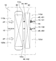
- FIG. 1 It is sectional drawing of the air-conditioning unit which concerns on 1st Embodiment. It is a schematic diagram which shows the 1st heat exchanger, the 2nd heat exchanger, and the vicinity thereof in the passage of the air conditioning unit which concerns on 1st Embodiment. It is a perspective view which looked at the PTC heater as a 2nd heat exchanger from the upstream side of the air flow. It is a perspective view which looked at the PTC heater as a 2nd heat exchanger from the downstream side of an air flow. It is explanatory drawing which shows the state of assembling the second heat exchanger from the opening of the air-conditioning case. It is explanatory drawing which shows the state of assembling the second heat exchanger from the opening of the air-conditioning case.
- FIG. 1 It is a front view of the dummy heat exchanger as the second heat exchanger provided in the air conditioning unit which concerns on 7th Embodiment. It is sectional drawing of the XIV-XIV line of FIG. It is a schematic diagram which shows the 1st heat exchanger, the 2nd heat exchanger and the vicinity thereof in the passage of the air conditioning unit of the comparative example.
- the air conditioning unit 1 of the present embodiment is arranged inside an instrument panel of a vehicle (not shown).
- the air-conditioning unit 1 sucks in one or both of the vehicle interior air (hereinafter referred to as "inside air") and the vehicle interior outside air (hereinafter referred to as "outside air”), and blows air-conditioned air into the vehicle interior in which the temperature and humidity of the sucked air are adjusted. By blowing it out, the interior of the vehicle is air-conditioned.
- the air conditioning unit 1 of the present embodiment is configured to be able to set a two-layer mode of inside / outside air to be supplied to the vehicle interior in a state where the inside air and the outside air are separated.
- the air conditioning unit 1 includes an air conditioning case 10, an evaporator 20, a heater core 30 as an example of a first heat exchanger, a PTC heater 40 as an example of a second heat exchanger, and air mix doors 51 and 52. And mode doors 61, 62, 63 and the like.
- the PTC heater is an abbreviation for Positive Temperature Coefficient heater.
- the air conditioning case 10 included in the air conditioning unit 1 is made of a resin (for example, polypropylene) having a certain degree of elasticity and excellent strength.
- the air conditioning case 10 has a passage through which air flows inside the outer wall. Further, the air conditioning case 10 has a plurality of partition walls for dividing the air flowing in the passage into the inside air and the outside air in the inside / outside air two-layer mode and supplying the air to the vehicle interior.
- first upstream partition walls 11 those provided on the upstream side of the evaporator 20 are referred to as first upstream partition walls 11, and those provided between the evaporator 20 and the heater core 30. Is called the second upstream partition wall 12. Further, among the plurality of partition walls provided in the air conditioning case 10, those provided on the downstream side of the PTC heater 40 are referred to as downstream case partition walls 13.
- the first upstream partition wall 11 divides the passage on the upstream side of the evaporator 20 into the first passage 110a and the second passage 120a.
- the second upstream partition wall 12 divides the passage between the evaporator 20 and the heater core 30 into the first passage 110b and the second passage 120b.
- the downstream case partition wall 13 divides a part of the passage on the downstream side of the PTC heater 40 into a first passage 110d and a second passage 120d.
- the first passages 110a to 110a are regions above the plurality of partition walls in FIG. 1, and are passages through which outside air flows in the inside / outside air two-layer mode.
- the second passages 120a to 120a are regions below the plurality of partition walls in FIG.
- a to d are added to the end of reference numeral 110 according to the position of the first passage 110.
- a to d are added to the end of reference numeral 120 according to the position of the second passage 120.
- air is introduced from the blower unit 70 into the first passage 110a and the second passage 120a on the upstream side of the evaporator 20.
- the blower unit 70 is configured to allow air introduced from at least one of the inside air introduction port 71 and the outside air introduction port 72 by driving a blower (not shown) to flow into the first passage 110a and the second passage 120a on the upstream side of the evaporator 20. Has been done.
- the blower unit 70 is configured to flow the outside air introduced from the outside air introduction port 72 to the first passage 110a and the inside air introduced from the inside air introduction port 71 to the second passage 120a in the inside / outside air two-layer mode. Has been done. Therefore, in the inside / outside air two-layer mode, outside air flows through the first passages 110a to 110, and inside air flows through the second passages 120a to 120a.
- the air conditioning case 10 has a plurality of blowout openings 17, 18, and 19 for blowing out the air flowing through the passage into the vehicle interior on the downstream side of each heat exchanger. Therefore, the inside air and the outside air taken in from at least one of the outside air introduction port 72 and the inside air introduction port 71 of the blower unit 70 flow through the passage in the air conditioning case 10 and are supplied to the vehicle interior.
- the plurality of outlet openings 17, 18 and 19 are composed of a defroster outlet opening 17, a face outlet opening 18, and a foot outlet opening 19.
- the defroster blowout opening 17 blows out air-conditioning air toward the front window glass of the vehicle.
- the face blowing opening 18 blows air-conditioning air toward the upper body of the occupant seated in the front seat.
- the foot blowing opening 19 blows air-conditioning air toward the feet of the occupant seated in the front seat.
- a duct (not shown) is attached to each of the outlet openings 17, 18, and 19. The duct is connected to each outlet provided at a predetermined location in the vehicle interior.
- the evaporator 20 is a refrigerant type heat exchanger for cooling the air flowing through the passage of the air conditioning case 10.
- the evaporator 20 constitutes a well-known refrigeration cycle together with a compressor, a condenser, an expansion valve and the like (not shown).
- the evaporator 20 is arranged on the downstream side of the expansion valve and on the upstream side of the compressor in the refrigeration cycle.
- a refrigerant that has been decompressed by an expansion valve and is in a gas-liquid two-layer state flows inside a tube (not shown) included in the evaporator 20.
- the evaporator 20 is configured to cool the air by heat exchange between the refrigerant flowing inside the tube and the air passing outside the tube.
- the first heat exchanger regulates the temperature of the air flowing through the passage of the air conditioning case 10.
- the heater core 30 as the first heat exchanger is a hot water heat exchanger for heating the air flowing through the passage of the air conditioning case 10.
- the heater core 30 is provided on the downstream side of the air flow with respect to the evaporator 20 in the passage of the air conditioning case 10.
- a heat medium such as engine cooling water flows inside a tube (not shown) included in the heater core 30.
- the heater core 30 is configured to heat the air by heat exchange between the heat medium flowing inside the tube and the air passing outside the tube.
- the second heat exchanger is provided on the downstream side of the air flow with respect to the first heat exchanger described above.
- the arrow AF in FIG. 2 indicates the air flow direction.
- the PTC heater 40 as the second heat exchanger and the heater core 30 as the first heat exchanger are arranged substantially in parallel and close to each other.
- the PTC heater 40 is an electric heat exchanger for heating the air flowing through the passage of the air conditioning case 10.
- the PTC heater 40 energizes an electric resistor to generate heat.
- the PTC heater 40 is configured to heat the air by heat exchange between the heat radiation fins formed including the electric resistor and the air passing between the heat radiation fins.
- An intermediate partition wall 44 is provided on the surface of the PTC heater 40 on the heater core 30 side.
- the intermediate partition wall 44 divides the passage between the heater core 30 and the PTC heater 40 into a first passage 110c and a second passage 120c.
- a downstream partition wall 45 is provided on the surface of the PTC heater 40 opposite to the heater core 30 side. The downstream partition wall 45 divides a part of the passage on the downstream side of the air flow from the PTC heater 40 into the first passage 110d and the second passage 120d.
- downstream partition wall 45 provided in the PTC heater 40 is configured to be fitted to the downstream case partition wall 13 provided in the air conditioning case 10. Specifically, a guide groove 46 recessed on the PTC heater 40 side is provided at a portion of the downstream partition wall 45 opposite to the PTC heater 40. A part of the downstream case partition wall 13 is fitted inside the guide groove 46.
- air mix doors 51 and 52 and a plurality of mode doors 61, 62 and 63 are provided in the passage of the air conditioning case 10.
- the air mix doors 51 and 52 are composed of two sliding doors provided between the evaporator 20 and the heater core 30.
- the air mix doors 51 and 52 are arranged so that all the air that has passed through the evaporator 20 flows through the heater core 30.
- the positions of the air mix doors 51 and 52 are switched according to the selected air conditioning mode.
- the plurality of mode doors 61, 62, 63 are composed of a defroster door 61, a face door 62, and a foot door 63.
- the defroster door 61 adjusts the amount of air blown from the defroster blowout opening 17.
- the face door 62 adjusts the amount of air blown from the face blowout opening 18.
- the foot door 63 adjusts the amount of air blown from the foot blowout opening 19.
- the positions of the plurality of mode doors 61, 62, 63 are also switched according to the air conditioning mode selected.
- FIGS. 3 and 4 indicate the air flow direction when the PTC heater 40 is installed in the air conditioning case 10.
- the PTC heater 40 has a heat radiation fin 41, a frame 42, a flange 43, and the like. Further, the intermediate partition wall 44 and the downstream partition wall 45 are integrally formed with the frame 42 and the flange 43 of the PTC heater 40.
- the heat radiating fins 41 of the PTC heater 40 are formed to include an electric resistor that generates heat when energized, and are arranged in parallel at predetermined intervals. When the air passes between the plurality of heat radiation fins 41, the air is heated.
- the frame 42 constitutes the outer frame of the heat radiation fins 41.
- the frame 42 is made of a resin (for example, PA66 / GF) having excellent heat resistance, rigidity, dimensional stability, and the like.
- the flange 43 is provided at one end of the frame 42.
- the flange 43 is also made of a resin having the same characteristics as the frame 42.
- a connector (not shown) for energizing the electric resistor is provided at a portion of the flange 43 opposite to the heat radiation fin 41.
- the intermediate partition wall 44 is provided on the surface of the PTC heater 40 on the upstream side of the air flow (that is, on the heater core 30 side).
- the intermediate partition wall 44 is also made of a resin having the same characteristics as the frame 42 and the flange 43.
- the intermediate partition wall 44, the frame 42, and the flange 43 are integrally formed of resin. That is, the intermediate partition wall 44 is connected to the frame 42 and the flange 43. Therefore, the intermediate partition wall 44 has a high rigidity structure.
- the downstream partition wall 45 is provided on the surface of the PTC heater 40 on the downstream side of the air flow (that is, on the side opposite to the heater core 30).
- the downstream partition wall 45 is also made of a resin having the same characteristics as the frame 42 and the flange 43.
- the downstream partition wall 45, the frame 42, and the flange 43 are integrally formed of resin. That is, the downstream partition wall 45 is connected to the frame 42 and the flange 43. Therefore, the downstream partition wall 45 also has a highly rigid structure.
- FIGS. 5 and 6 show how the PTC heater 40 is assembled to the air conditioning case 10.
- An opening 15 for attaching / detaching the PTC heater 40 is provided on the outer wall of the air conditioning case 10.
- FIGS. 5 and 6 the direction in which the PTC heater 40 is assembled from the opening 15 of the air conditioning case 10 into the passage is indicated by an arrow R.
- the opening 15 of the air conditioning case 10 is formed to have a size so that the heater core 30 can be attached and detached together with the PTC heater 40.
- the downstream partition wall 45 provided in the PTC heater 40 has a guide groove 46 that fits into the downstream case partition wall 13 provided in the air conditioning case 10. .. Therefore, when the PTC heater 40 is inserted into the passage through the opening 15 of the air conditioning case 10, it can be performed as shown in FIG. That is, as shown in FIG. 6, the PTC heater 40 is passed through the PTC heater 40 in a state where the guide groove 46 of the downstream partition wall 45 and the end 131 of the downstream case partition wall 13 on the PTC heater 40 side are fitted. It is possible to slide it in. As a result, the PTC heater 40 is inserted into the passage without being displaced vertically and horizontally. Therefore, the end portion 420 of the PTC heater 40 on the side opposite to the flange 43 can be easily and surely fitted into the fitting portion 14 provided on the side opposite to the opening 15 of the air conditioning case 10. ..
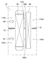
- FIG. 15 is an enlarged view of the heater core 30, the PTC heater 40, and the vicinity thereof provided in the air conditioning unit of the comparative example, and shows the locations corresponding to FIG. 2 of the first embodiment described above.
- the intermediate partition wall 440 is provided in the air conditioning case 10. That is, both ends of the intermediate partition wall 440 (that is, the portion of the intermediate partition wall 440 on the front side and the back side of the paper surface in FIG. 15) are connected to the inner wall of the air conditioner case 10.
- the heater core 30 and the PTC heater 40 are arranged close to each other. Therefore, the width of the intermediate partition wall 440 becomes narrower, the distinction between the inside air and the outside air deteriorates due to poor molding of the intermediate partition wall 440, the intermediate partition wall 440 is damaged due to insufficient rigidity, or the left and right sides constituting the air conditioning case 10 are formed. There is a risk of problems such as improper fitting of the split case parts.
- the downstream partition wall is not provided on the side of the PTC heater 40 opposite to the heater core 30. Therefore, when the PTC heater 40 is inserted into the passage through the opening 15 of the air conditioning case 10, the PTC heater 40 is likely to be displaced vertically and horizontally. Therefore, in the comparative example, when the PTC heater 40 is assembled, the end portion 420 of the PTC heater 40 on the side opposite to the flange 43 is fitted into the fitting portion 14 provided on the side opposite to the opening 15 of the air conditioner case 10. The structure is difficult to put in.
- the air-conditioning unit 1 of the first embodiment has the following effects with respect to the air-conditioning unit of the comparative example described above.
- the intermediate partition wall 44 is provided on the surface of the PTC heater 40 on the heater core 30 side.
- the area where the PTC heater 40 and the intermediate partition wall 44 are connected becomes large, so that even if the width of the intermediate partition wall 44 is narrowed, the rigidity of the intermediate partition wall 44 can be increased, and the rigidity of the intermediate partition wall 44 can be increased.
- the sex is also good.
- the air conditioning case 10 and the intermediate partition wall 44 are separate members, even if the width of the intermediate partition wall 44 is narrowed, there is a problem that the left and right split case parts constituting the air conditioning case 10 are poorly fitted to each other. Does not occur. Therefore, in the air conditioning unit 1, the heater core 30 and the PTC heater 40 can be arranged close to each other, and the physique of the air conditioning unit 1 can be miniaturized.
- the downstream partition wall 45 is provided on the surface of the PTC heater 40 opposite to the heater core 30.
- the area where the PTC heater 40 and the downstream partition wall 45 are connected becomes large, so that even if the width of the downstream partition wall 45 is narrowed, the rigidity of the downstream partition wall 45 can be increased. , The moldability is also improved.
- the air conditioning case 10 and the downstream partition wall 45 are separate members, even if the width of the downstream partition wall 45 is narrowed, the left and right split case parts constituting the air conditioning case 10 will not fit each other. There is no such problem. Therefore, the air conditioning unit 1 can make the downstream partition wall 45 thinner, and the physique of the air conditioning unit 1 can be miniaturized.
- the PTC heater 40 includes a downstream partition wall 45 provided on the downstream surface of the PTC heater 40 and a downstream case partition wall 13 provided on the air conditioning case 10. Can be attached and detached through the opening 15 of the air conditioning case 10 in a state of being fitted. According to this, it is possible to improve the assembling property of the PTC heater 40 with respect to the air conditioning case 10. Therefore, the cycle time at the time of manufacturing can be shortened, and the manufacturing cost can be reduced.
- the frame 42 of the PTC heater 40, the intermediate partition wall 44, and the downstream partition wall 45 are integrally formed. As a result, the rigidity of the intermediate partition wall 44 and the downstream partition wall 45 can be increased, and the manufacturing cost can be reduced.
- the second embodiment will be described.
- the second embodiment is different from the first embodiment because the configurations of the intermediate partition wall 44 and the downstream partition wall 45 are changed from those of the first embodiment, and the other parts are the same as those of the first embodiment. Only the different parts will be described.
- the intermediate partition wall 44 and the downstream partition wall 45 are both in a plurality of stages. Specifically, both the intermediate partition wall 44 and the downstream partition wall 45 have two steps.
- the one provided on the upper side that is, the defroster outlet opening 17 side
- the first intermediate partition wall 441 is called the first intermediate partition wall 441
- the second intermediate partition wall 442 is provided on the lower side with respect to the first intermediate partition wall 441.
- the one provided on the upper side is called the first downstream partition wall 451 and the one provided on the lower side with respect to the first downstream partition wall 451 is called the first downstream partition wall 451. It is called the downstream partition wall 452.
- the downstream case partition wall 13 is also provided with two steps.
- the one provided on the upper side is called the first downstream side case partition wall 131
- the one provided on the lower side with respect to the first intermediate partition wall 441 is called the second downstream side case partition wall 131.
- It is called a side case partition wall 132.
- the first downstream partition wall 451 and the second downstream partition wall 452 are provided at positions corresponding to their ends when the foot door 63 is rotationally driven. Therefore, the air conditioning unit 1 of the second embodiment can finely adjust the air volume blown from each of the plurality of blowing openings 17, 18 and 19 according to the selected air conditioning mode.
- the first intermediate partition wall 441 and the first downstream partition wall 451 are provided at substantially the same height position of the PTC heater 40. Further, the second intermediate partition wall 442 and the second downstream partition wall 452 are also provided at substantially the same height position of the PTC heater 40.
- a guide groove 46 is provided in a portion of the first downstream partition wall 451 opposite to the PTC heater 40.
- the guide groove 46 provided in the first downstream side partition wall 451 is configured to fit into the first downstream side case partition wall 131.
- the second downstream partition wall 452 is not provided with a guide groove.
- the second downstream side partition wall 452 is provided so as to abut or be adjacent to the second downstream side case partition wall 132.
- the guide groove 46 of the first downstream partition wall 451 and the first downstream case partition wall 131 are fitted into the PTC. It is possible to slide the heater 40 into the passage. At that time, the second downstream side partition wall 452 and the second downstream side case partition wall 132 are in a sliding contact state. As a result, the PTC heater 40 can be easily inserted into the passage without the PTC heater 40 being displaced vertically and horizontally.
- the guide groove 46 is provided only in the first downstream partition wall 451 and the guide groove is not provided in the second downstream partition wall 452, the manufacturing tolerance of each member is increased. Even in such a case, deterioration of assembling property can be prevented.
- the third embodiment will be described.
- the third embodiment is a modification of the configuration of the downstream partition wall 45 with respect to the second embodiment, and the other parts are the same as those of the second embodiment. Therefore, only the parts different from the second embodiment will be described. To do.
- both the intermediate partition wall 44 and the downstream partition wall 45 have two stages.
- the guide grooves 461 and 462 are provided in both the first downstream side partition wall 451 and the second embodiment.
- the guide groove 461 provided in the first downstream side partition wall 451 is configured to fit into the first downstream side case partition wall 131.
- the guide groove 462 provided in the second downstream side partition wall 452 is configured to fit into the second downstream side case partition wall 132.
- the guide groove 461 of the first downstream side partition wall 451 and the first downstream side case partition wall 131 are fitted, and further, the guide groove 462 of the second downstream side partition wall 452 is fitted. And the second downstream side case partition wall 132 are fitted together. In that state, the PTC heater 40 is slid into the passage. As a result, the PTC heater 40 can be easily inserted into the passage without the PTC heater 40 being displaced vertically and horizontally.
- the fourth to sixth embodiments will be described.
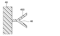
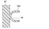
- the fourth to sixth embodiments are different from the first embodiment and the like in that the shape of the downstream partition wall 45 is changed, and the other parts are the same as those of the first embodiment and the like. Only the parts that differ from the above will be described.
- the cross section of the downstream partition wall 453 is Y-shaped.
- the cross section of the downstream partition wall 454 is U-shaped.
- the cross section of the downstream partition wall 455 has a shape in which two flat plates are arranged in parallel. As described above, various shapes can be adopted as the shape of the downstream partition wall.
- the seventh embodiment is a modification of the configuration of the second heat exchanger with respect to the first embodiment and the like, and the other parts are the same as those of the first embodiment and the like, and thus are different from the first embodiment and the like. Will be described only.
- the air conditioning unit 1 of the seventh embodiment replaces the PTC heater 40 illustrated in the first embodiment and the like, for example, a dummy heat exchanger as shown in FIGS. 13 and 14. 47 is provided.
- the dummy heat exchanger 47 does not have a heat exchange function and is composed of a member having a predetermined air resistance.
- the dummy heat exchanger 47 has a plate member 48, a flange 43, and the like.
- the plate member 48 has a plurality of holes 49 through which air passes.
- the ventilation resistance of the plate member 48 is set to be substantially the same as that of the PTC heater 40 illustrated in the first embodiment.
- the flange 43 is provided at one end of the plate member 48.
- the plate member 48 of the dummy heat exchanger 47 is provided with an intermediate partition wall 44 and a downstream partition wall 45.
- the plate member 48 of the dummy heat exchanger 47, the intermediate partition wall 44, and the downstream partition wall 45 are integrally formed.
- the air conditioning unit 1 of the seventh embodiment can also increase the rigidity of the intermediate partition wall 44 and the downstream partition wall 45 provided in the dummy heat exchanger 47 as the second heat exchanger. It is possible and its moldability is also good. Then, the heater core 30 and the dummy heat exchanger 47 can be arranged close to each other. Therefore, the seventh embodiment can also exhibit the same effects as those of the first embodiment and the like.
- the heater core 30 has been exemplified as the first heat exchanger, but the present invention is not limited to this.
- the first heat exchanger is, for example, a heat medium type heat exchanger through which a heat medium other than engine cooling water flows, a refrigerant type heat exchanger composed of a refrigerating cycle capacitor, or a refrigerating cycle evaporator 20. It may be a refrigerant type heat exchanger configured by the above.
- the PTC heater 40 and the dummy heat exchanger 47 are exemplified as the second heat exchanger, but the present invention is not limited to this.
- the second heat exchanger is, for example, a refrigerant composed of an electric heat exchanger other than the PTC heater 40, a heat medium type heat exchanger through which engine cooling water or other heat medium flows, a refrigerating cycle condenser, or the like. It may be a type heat exchanger or the like.
- the intermediate partition wall 44 between the first heat exchanger and the second heat exchanger has been described as being provided in the second heat exchanger, but the present invention is not limited to this.
- the intermediate partition wall 44 may be provided in the first heat exchanger, or may be provided in both the first heat exchanger and the second heat exchanger.
- the intermediate partition wall 44 and the downstream partition wall 45 have two stages, but the present invention is not limited to this.
- the number of stages of the intermediate partition wall 44 and the downstream partition wall 45 can be arbitrarily set according to the performance required for the air conditioning unit 1.
- the opening 15 of the air conditioning case 10 has a heater core 30 that can be attached to and detached from the PTC heater 40, but the present invention is not limited to this.
- the opening 15 of the air conditioner case 10 may be provided with a first opening to which only the PTC heater 40 can be attached and detached and a second opening to which the heater core 30 can be attached and detached separately.
- the air conditioning configured so that the inside / outside air two-layer mode in which the vehicle interior air and the vehicle interior / outdoor air are separately supplied to the vehicle interior can be set.
- the unit includes an air conditioning case, a first heat exchanger, a second heat exchanger, an upstream partition wall and an intermediate partition wall.
- the air-conditioning case has a passage for flowing air introduced from at least one of the inside air introduction port for introducing the vehicle interior air and the outside air introduction port for introducing the vehicle interior outside air toward the vehicle interior.
- the first heat exchanger is installed in the passage of the air conditioning case and regulates the temperature of the air flowing through the passage.
- the second heat exchanger is installed on the downstream side of the air flow of the first heat exchanger in the passage of the air conditioning case.
- the upstream partition wall is a passage on the upstream side of the air flow from the first heat exchanger, a first passage through which the outside air flows in the inside / outside air two-layer mode, and a second passage through which the inside / outside air flows in the two-layer mode. Divide into passages.
- the intermediate partition wall is provided on at least one of the first heat exchanger and the second heat exchanger, and the passage between the first heat exchanger and the second heat exchanger is divided into a first passage and a second passage. To do.
- the air conditioning unit further includes a downstream partition wall.
- the downstream partition wall is provided on the surface of the second heat exchanger opposite to the first heat exchanger, and a part of the passage on the downstream side of the air flow from the second heat exchanger is the first passage and the first passage. Divide into 2 passages. According to this, the area where the second heat exchanger and the downstream partition wall are connected becomes large. Therefore, even when the width of the downstream partition wall is narrowed, the rigidity of the downstream partition wall can be increased, and the moldability thereof is also improved. Further, there is no problem that the left and right split case parts constituting the air-conditioning case are not fitted properly. Therefore, in this air conditioning unit, the downstream partition wall can be made thin, and the physique of the air conditioning unit can be miniaturized.
- the air-conditioning case has an opening formed in a part of the outer wall to allow the second heat exchanger to be attached and detached, and a part of the passage on the downstream side of the air flow from the downstream partition wall. It has a downstream case partition wall that divides the first passage and the second passage.
- the second heat exchanger has a configuration in which the downstream partition wall and the downstream case partition wall are fitted to each other and can be attached to and detached from the air conditioner through the opening of the air conditioning case. According to this, it is possible to improve the assemblability of the second heat exchanger to the air conditioning case. Therefore, the cycle time at the time of manufacturing can be shortened, and the manufacturing cost can be reduced.
- At least one of the intermediate partition wall and the downstream partition wall is provided in a plurality of stages. According to this, it is possible to finely adjust the amount of air blown from each of the plurality of blowout openings of the air conditioning case.
- the second heat exchanger is any one of an electric heat exchanger, a refrigerant heat exchanger, a heat medium heat exchanger, and a dummy heat exchanger.
- the intermediate partition wall is integrally formed with the frame or plate member of the second heat exchanger. According to this, by integrally forming the intermediate partition wall and the frame or plate member of the second heat exchanger, it is possible to increase the rigidity of the intermediate partition wall and reduce the manufacturing cost. can do.
- the second heat exchanger is any one of an electric heat exchanger, a refrigerant heat exchanger, a heat medium heat exchanger, and a dummy heat exchanger.
- the downstream partition wall is integrally formed with the frame or plate member of the second heat exchanger. According to this, by integrally forming the downstream partition wall and the frame or plate member of the second heat exchanger, the rigidity of the downstream partition wall can be increased and the manufacturing cost can be increased. Can be reduced.
- the air conditioning unit configured to be able to set the inside / outside air two-layer mode in which the vehicle interior air and the vehicle interior / outdoor air are separately supplied to the vehicle interior includes an air conditioning case, a first heat exchanger, and a first heat exchanger. 2 It is equipped with a heat exchanger, an upstream partition wall and a downstream partition wall.
- the air-conditioning case has a passage for flowing air introduced from at least one of the inside air introduction port for introducing the vehicle interior air and the outside air introduction port for introducing the vehicle interior outside air toward the vehicle interior.
- the first heat exchanger is installed in the passage of the air conditioning case and regulates the temperature of the air flowing through the passage.
- the second heat exchanger is installed on the downstream side of the air flow of the first heat exchanger in the passage of the air conditioning case.
- the upstream partition wall is a passage on the upstream side of the air flow from the first heat exchanger, a first passage through which the outside air flows in the inside / outside air two-layer mode, and a second passage through which the inside / outside air flows in the two-layer mode. Divide into passages.
- the downstream partition wall is provided on the surface of the second heat exchanger opposite to the first heat exchanger, and a part of the passage on the downstream side of the air flow from the second heat exchanger is the first passage and the first passage. Divide into 2 passages.
Abstract
An air conditioner case (10) has a passage through which air introduced from an inside-air inlet (71) and/or an outside-air inlet (72) flows into a vehicle cabin. A first heat exchanger (30) is installed inside the air conditioner case (10), and adjusts the temperature of the air flowing through the passage. A second heat exchanger (40, 47) is installed downstream, in terms of the air flow, of the first heat exchanger (30) inside the air conditioner case (10). An upstream-side partition wall (11, 12) divides the passage upstream, in terms of the air flow, of the first heat exchanger (30) into a first passage (110) through which air from outside the vehicle cabin flows in an inside/outside air two-layer mode and a second passage (120) through which air from inside the vehicle cabin flows in the inside/outside air two-layer mode. An intermediate partition wall (44) is provided to at least one of the first heat exchanger (30) and the second heat exchanger (40, 47), and divides the passage between the first heat exchanger (30) and the second heat exchanger (40, 47) into the first passage (110) and the second passage (120).
Description
本出願は、2019年10月30日に出願された日本特許出願番号2019-197867号に基づくもので、ここにその記載内容が参照により組み入れられる。
This application is based on Japanese Patent Application No. 2019-197867 filed on October 30, 2019, the contents of which are incorporated herein by reference.
本開示は、車両用の空調ユニットに関するものである。
This disclosure relates to an air conditioning unit for a vehicle.
従来、車室内の空調を行う空調ユニットにおいて、車室内空気(以下、「内気」という)および車室外空気(以下、「外気」という)を区分して車室内に供給する内外気二層モードを設定可能に構成されたものが知られている。
特許文献1に記載の空調ユニットは、空調ケース内の通路を、内外気二層モード時に外気が流れる第1通路と、内気が流れる第2通路とに区画するための複数の仕切壁を備えている。複数の仕切壁はそれぞれ、エバポレータより上流側、エバポレータとヒータコアとの間、ヒータコアと補助ヒータとの間、および、補助ヒータより下流側に設けられている。そして、特許文献1では、全ての仕切壁と空調ケースとが樹脂により一体に形成されている。 Conventionally, in an air conditioning unit that air-conditions the interior of a vehicle, a two-layer mode of inside / outside air that separates the air inside the vehicle (hereinafter referred to as "inside air") and the outside air of the vehicle (hereinafter referred to as "outside air") and supplies the air to the inside of the vehicle is used. Known are configured to be configurable.
The air conditioning unit described inPatent Document 1 includes a plurality of partition walls for partitioning a passage in an air conditioning case into a first passage through which outside air flows and a second passage through which inside air flows in a two-layer mode of inside and outside air. There is. The plurality of partition walls are provided on the upstream side of the evaporator, between the evaporator and the heater core, between the heater core and the auxiliary heater, and on the downstream side of the auxiliary heater, respectively. In Patent Document 1, all the partition walls and the air conditioner case are integrally formed of resin.
特許文献1に記載の空調ユニットは、空調ケース内の通路を、内外気二層モード時に外気が流れる第1通路と、内気が流れる第2通路とに区画するための複数の仕切壁を備えている。複数の仕切壁はそれぞれ、エバポレータより上流側、エバポレータとヒータコアとの間、ヒータコアと補助ヒータとの間、および、補助ヒータより下流側に設けられている。そして、特許文献1では、全ての仕切壁と空調ケースとが樹脂により一体に形成されている。 Conventionally, in an air conditioning unit that air-conditions the interior of a vehicle, a two-layer mode of inside / outside air that separates the air inside the vehicle (hereinafter referred to as "inside air") and the outside air of the vehicle (hereinafter referred to as "outside air") and supplies the air to the inside of the vehicle is used. Known are configured to be configurable.
The air conditioning unit described in
ところで、車両に搭載される空調ユニットには、車両搭載の制約により体格の小型化が要求される。その要求を満たすため、特許文献1に記載の構成において、ヒータコアと補助ヒータとを近づけて配置することが考えられる。しかし、その場合、ヒータコアと補助ヒータとの間の仕切壁(以下、中間仕切壁という)の幅が細くなる。上述したように、特許文献1では、全ての仕切壁と空調ケースとが一体に形成されており、中間仕切壁も空調ケースと一体に形成されている。そのため、中間仕切壁の幅を細くすると、中間仕切壁の成形不良、中間仕切壁の剛性不足、または、空調ケースを構成する左右の分割ケース部品同士の嵌合不良などの不具合が生じるおそれがある。したがって、特許文献1に記載の空調ユニットは、体格を小型化することが困難な構成となっている。
By the way, the air-conditioning unit mounted on the vehicle is required to be downsized due to the restrictions on the vehicle mounting. In order to satisfy the requirement, it is conceivable to arrange the heater core and the auxiliary heater close to each other in the configuration described in Patent Document 1. However, in that case, the width of the partition wall (hereinafter referred to as an intermediate partition wall) between the heater core and the auxiliary heater becomes narrow. As described above, in Patent Document 1, all the partition walls and the air-conditioning case are integrally formed, and the intermediate partition wall is also integrally formed with the air-conditioning case. Therefore, if the width of the intermediate partition wall is narrowed, problems such as poor molding of the intermediate partition wall, insufficient rigidity of the intermediate partition wall, or improper fitting of the left and right split case parts constituting the air conditioning case may occur. .. Therefore, the air conditioning unit described in Patent Document 1 has a configuration in which it is difficult to reduce the physique.
本開示は、体格を小型化することの可能な空調ユニットを提供することを目的とする。
The purpose of this disclosure is to provide an air conditioning unit capable of downsizing the physique.
本開示の1つの観点によれば、車室内空気および車室外空気を区分して車室内に供給する内外気二層モードを設定可能に構成される空調ユニットは、空調ケース、第1熱交換器、第2熱交換器、上流側仕切壁および中間仕切壁を備える。空調ケースは、車室内空気を導入する内気導入口および車室外空気を導入する外気導入口の少なくとも一方から導入される空気を車室内へ向けて流す通路を有する。第1熱交換器は、空調ケースの通路内に設置され、通路を流れる空気の温度を調整する。第2熱交換器は、空調ケースの通路のうち第1熱交換器の空気流れ下流側に設置される。上流側仕切壁は、第1熱交換器よりも空気流れ上流側の通路を、内外気二層モード時に車室外空気が流れる第1通路と、内外気二層モード時に車室内空気が流れる第2通路とに区画する。中間仕切壁は、第1熱交換器および第2熱交換器の少なくとも一方に設けられ、第1熱交換器と第2熱交換器との間の通路を第1通路と第2通路とに区画する。
According to one aspect of the present disclosure, the air conditioning unit configured to be able to set the inside / outside air two-layer mode in which the vehicle interior air and the vehicle interior / outdoor air are separately supplied to the vehicle interior is an air conditioning case and a first heat exchanger. , A second heat exchanger, an upstream partition wall and an intermediate partition wall. The air-conditioning case has a passage for flowing air introduced from at least one of the inside air introduction port for introducing the vehicle interior air and the outside air introduction port for introducing the vehicle interior outside air toward the vehicle interior. The first heat exchanger is installed in the passage of the air conditioning case and regulates the temperature of the air flowing through the passage. The second heat exchanger is installed on the downstream side of the air flow of the first heat exchanger in the passage of the air conditioning case. The upstream partition wall is a passage on the upstream side of the air flow from the first heat exchanger, a first passage through which the outside air flows in the inside / outside air two-layer mode, and a second passage through which the inside / outside air flows in the two-layer mode. Divide into passages. The intermediate partition wall is provided on at least one of the first heat exchanger and the second heat exchanger, and the passage between the first heat exchanger and the second heat exchanger is divided into a first passage and a second passage. To do.
これによれば、第1熱交換器および第2熱交換器の少なくとも一方と中間仕切壁とが接続する面積が大きくなるので、中間仕切壁の幅を細くした場合でも、中間仕切壁の剛性を高くすることが可能であり、その成形性も良好になる。また、空調ケースと中間仕切壁とを別部材としているので、中間仕切壁の幅を細くした場合でも、空調ケースを構成する左右の分割ケース部品同士が嵌合不良になるといった問題は発生しない。したがって、この空調ユニットは、第1熱交換器と第2熱交換器とを近づけて配置することが可能であり、空調ユニットの体格を小型化することができる。
According to this, since the area where at least one of the first heat exchanger and the second heat exchanger is connected to the intermediate partition wall becomes large, the rigidity of the intermediate partition wall can be increased even if the width of the intermediate partition wall is narrowed. It can be made higher, and its moldability is also improved. Further, since the air-conditioning case and the intermediate partition wall are made of separate members, even if the width of the intermediate partition wall is narrowed, the problem that the left and right split case parts constituting the air-conditioning case do not fit together does not occur. Therefore, in this air conditioning unit, the first heat exchanger and the second heat exchanger can be arranged close to each other, and the physique of the air conditioning unit can be miniaturized.
また、別の観点によれば、車室内空気および車室外空気を区分して車室内に供給する内外気二層モードを設定可能に構成される空調ユニットは、空調ケース、第1熱交換器、第2熱交換器、上流側仕切壁および下流側仕切壁を備える。空調ケースは、車室内空気を導入する内気導入口および車室外空気を導入する外気導入口の少なくとも一方から導入される空気を車室内へ向けて流す通路を有する。第1熱交換器は、空調ケースの通路内に設置され、通路を流れる空気の温度を調整する。第2熱交換器は、空調ケースの通路のうち第1熱交換器の空気流れ下流側に設置される。上流側仕切壁は、第1熱交換器よりも空気流れ上流側の通路を、内外気二層モード時に車室外空気が流れる第1通路と、内外気二層モード時に車室内空気が流れる第2通路とに区画する。下流側仕切壁は、第2熱交換器のうち第1熱交換器とは反対側の面に設けられ、第2熱交換器よりも空気流れ下流側の通路の一部を第1通路と第2通路とに区画する。
From another point of view, the air conditioning unit configured to be able to set the inside / outside air two-layer mode that separates the vehicle interior air and the vehicle interior / outside air and supplies them to the vehicle interior includes an air conditioning case, a first heat exchanger, and the like. It is provided with a second heat exchanger, an upstream partition wall and a downstream partition wall. The air-conditioning case has a passage for flowing air introduced from at least one of the inside air introduction port for introducing the vehicle interior air and the outside air introduction port for introducing the vehicle interior outside air toward the vehicle interior. The first heat exchanger is installed in the passage of the air conditioning case and regulates the temperature of the air flowing through the passage. The second heat exchanger is installed on the downstream side of the air flow of the first heat exchanger in the passage of the air conditioning case. The upstream partition wall is a passage on the upstream side of the air flow from the first heat exchanger, a first passage through which the outside air flows in the inside / outside air two-layer mode, and a second passage through which the inside / outside air flows in the two-layer mode. Divide into passages. The downstream partition wall is provided on the surface of the second heat exchanger opposite to the first heat exchanger, and a part of the passage on the downstream side of the air flow from the second heat exchanger is the first passage and the first passage. Divide into 2 passages.
これによれば、第2熱交換器と下流側仕切壁とが接続する面積が大きくなるので、下流側仕切壁の幅を細くした場合でも、下流側仕切壁の剛性を高くすることが可能であり、その成形性も良好になる。また、空調ケースと下流側仕切壁とを別部材としているので、中間仕切壁の幅を細くした場合でも、空調ケースを構成する左右の分割ケース部品同士が嵌合不良になるといった問題は発生しない。したがって、この空調ユニットは、下流側仕切壁を細くすることが可能であり、空調ユニットの体格を小型化することができる。
According to this, since the area where the second heat exchanger and the downstream partition wall are connected becomes large, it is possible to increase the rigidity of the downstream partition wall even when the width of the downstream partition wall is narrowed. Yes, and its moldability is also good. In addition, since the air-conditioning case and the downstream partition wall are separate members, even if the width of the intermediate partition wall is narrowed, there is no problem that the left and right split case parts that make up the air-conditioning case are poorly fitted. .. Therefore, in this air conditioning unit, the downstream partition wall can be made thin, and the physique of the air conditioning unit can be miniaturized.
なお、各構成要素等に付された括弧付きの参照符号は、その構成要素等と後述する実施形態に記載の具体的な構成要素等との対応関係の一例を示すものである。
Note that the reference symbols in parentheses attached to each component or the like indicate an example of the correspondence between the component or the like and the specific component or the like described in the embodiment described later.
以下、本開示の実施形態について図面を参照しつつ説明する。なお、以下の各実施形態相互において、互いに同一もしくは均等である部分には、同一符号を付し、その説明を省略する。なお、以下の説明において、「上」「下」「左」「右」の用語は、説明の便宜上使用するものであり、空調ユニットが設置される方向を限定するものではない。
Hereinafter, embodiments of the present disclosure will be described with reference to the drawings. In each of the following embodiments, the same or equal parts are designated by the same reference numerals, and the description thereof will be omitted. In the following description, the terms "upper", "lower", "left", and "right" are used for convenience of explanation, and do not limit the direction in which the air conditioning unit is installed.
(第1実施形態)
第1実施形態について図面を参照しつつ説明する。本実施形態の空調ユニット1は、図示しない車両のインストルメントパネルの内側に配置される。空調ユニット1は、車室内空気(以下「内気」という)と車室外空気(以下「外気」という)の一方または両方を吸い込み、その吸い込んだ空気の温度および湿度を調整した空調風を車室内に吹き出すことにより、車室内の空調を行うものである。また、本実施形態の空調ユニット1は、内気と外気とを分けた状態で車室内に供給する内外気二層モードを設定可能に構成されている。 (First Embodiment)
The first embodiment will be described with reference to the drawings. Theair conditioning unit 1 of the present embodiment is arranged inside an instrument panel of a vehicle (not shown). The air-conditioning unit 1 sucks in one or both of the vehicle interior air (hereinafter referred to as "inside air") and the vehicle interior outside air (hereinafter referred to as "outside air"), and blows air-conditioned air into the vehicle interior in which the temperature and humidity of the sucked air are adjusted. By blowing it out, the interior of the vehicle is air-conditioned. Further, the air conditioning unit 1 of the present embodiment is configured to be able to set a two-layer mode of inside / outside air to be supplied to the vehicle interior in a state where the inside air and the outside air are separated.
第1実施形態について図面を参照しつつ説明する。本実施形態の空調ユニット1は、図示しない車両のインストルメントパネルの内側に配置される。空調ユニット1は、車室内空気(以下「内気」という)と車室外空気(以下「外気」という)の一方または両方を吸い込み、その吸い込んだ空気の温度および湿度を調整した空調風を車室内に吹き出すことにより、車室内の空調を行うものである。また、本実施形態の空調ユニット1は、内気と外気とを分けた状態で車室内に供給する内外気二層モードを設定可能に構成されている。 (First Embodiment)
The first embodiment will be described with reference to the drawings. The
まず、本実施形態の空調ユニット1の全体構成について説明する。
図1に示すように、空調ユニット1は、空調ケース10、エバポレータ20、第1熱交換器の一例としてのヒータコア30、第2熱交換器の一例としてのPTCヒータ40、エアミックスドア51、52およびモードドア61、62、63などを備えている。なお、PTCヒータは、Positive Temperature Coefficientヒータの略である。 First, the overall configuration of theair conditioning unit 1 of the present embodiment will be described.
As shown in FIG. 1, theair conditioning unit 1 includes an air conditioning case 10, an evaporator 20, a heater core 30 as an example of a first heat exchanger, a PTC heater 40 as an example of a second heat exchanger, and air mix doors 51 and 52. And mode doors 61, 62, 63 and the like. The PTC heater is an abbreviation for Positive Temperature Coefficient heater.
図1に示すように、空調ユニット1は、空調ケース10、エバポレータ20、第1熱交換器の一例としてのヒータコア30、第2熱交換器の一例としてのPTCヒータ40、エアミックスドア51、52およびモードドア61、62、63などを備えている。なお、PTCヒータは、Positive Temperature Coefficientヒータの略である。 First, the overall configuration of the
As shown in FIG. 1, the
空調ユニット1が備える空調ケース10は、ある程度の弾性を有し、強度的にも優れた樹脂(例えばポリプロピレン)にて形成されている。空調ケース10は、外壁の内側に空気が流れる通路を有している。また、空調ケース10は、通路内を流れる空気を内外気二層モード時に内気と外気とに区分して車室内に供給するための複数の仕切壁を有している。
The air conditioning case 10 included in the air conditioning unit 1 is made of a resin (for example, polypropylene) having a certain degree of elasticity and excellent strength. The air conditioning case 10 has a passage through which air flows inside the outer wall. Further, the air conditioning case 10 has a plurality of partition walls for dividing the air flowing in the passage into the inside air and the outside air in the inside / outside air two-layer mode and supplying the air to the vehicle interior.
以下の説明では、空調ケース10に設けられる複数の仕切壁のうち、エバポレータ20より上流側に設けられるものを第1上流側仕切壁11と呼び、エバポレータ20とヒータコア30との間に設けられるものを第2上流側仕切壁12と呼ぶ。また、空調ケース10に設けられる複数の仕切壁のうち、PTCヒータ40の下流側に設けられるものを下流側ケース仕切壁13と呼ぶ。
In the following description, among the plurality of partition walls provided in the air conditioning case 10, those provided on the upstream side of the evaporator 20 are referred to as first upstream partition walls 11, and those provided between the evaporator 20 and the heater core 30. Is called the second upstream partition wall 12. Further, among the plurality of partition walls provided in the air conditioning case 10, those provided on the downstream side of the PTC heater 40 are referred to as downstream case partition walls 13.
第1上流側仕切壁11は、エバポレータ20より上流側の通路を第1通路110aと第2通路120aに区画している。第2上流側仕切壁12は、エバポレータ20とヒータコア30との間の通路を第1通路110bと第2通路120bに区画している。下流側ケース仕切壁13は、PTCヒータ40の下流側の通路の一部を第1通路110dと第2通路120dに区画している。なお、第1通路110a~dは、図1において複数の仕切壁よりも上側の領域であり、内外気二層モード時に外気が流れる通路である。第2通路120a~dは、図1において複数の仕切壁よりも下側の領域であり、内外気二層モード時に内気が流れる通路である。
なお、本明細書および図面では、第1通路110の位置に応じて符号110の末尾にa~dを付している。第2通路120の位置に応じて符号120の末尾にa~dを付している。 The firstupstream partition wall 11 divides the passage on the upstream side of the evaporator 20 into the first passage 110a and the second passage 120a. The second upstream partition wall 12 divides the passage between the evaporator 20 and the heater core 30 into the first passage 110b and the second passage 120b. The downstream case partition wall 13 divides a part of the passage on the downstream side of the PTC heater 40 into a first passage 110d and a second passage 120d. The first passages 110a to 110a are regions above the plurality of partition walls in FIG. 1, and are passages through which outside air flows in the inside / outside air two-layer mode. The second passages 120a to 120a are regions below the plurality of partition walls in FIG. 1, and are passages through which the inside air flows in the inside / outside air two-layer mode.
In this specification and drawings, a to d are added to the end of reference numeral 110 according to the position of the first passage 110. A to d are added to the end of reference numeral 120 according to the position of the second passage 120.
なお、本明細書および図面では、第1通路110の位置に応じて符号110の末尾にa~dを付している。第2通路120の位置に応じて符号120の末尾にa~dを付している。 The first
In this specification and drawings, a to d are added to the end of reference numeral 110 according to the position of the first passage 110. A to d are added to the end of reference numeral 120 according to the position of the second passage 120.
空調ケース10内の通路のうち、エバポレータ20より上流側の第1通路110aと第2通路120aには、送風ユニット70から空気が導入される。送風ユニット70は、図示しない送風機の駆動により内気導入口71および外気導入口72の少なくとも一方から導入される空気をエバポレータ20よりも上流側の第1通路110aと第2通路120aに流すように構成されている。また、送風ユニット70は、内外気二層モード時に、外気導入口72から導入される外気を第1通路110aに流し、内気導入口71から導入される内気を第2通路120aに流すように構成されている。そのため、内外気二層モード時に、第1通路110a~dには外気が流れ、第2通路120a~dには内気が流れる。
Of the passages in the air conditioning case 10, air is introduced from the blower unit 70 into the first passage 110a and the second passage 120a on the upstream side of the evaporator 20. The blower unit 70 is configured to allow air introduced from at least one of the inside air introduction port 71 and the outside air introduction port 72 by driving a blower (not shown) to flow into the first passage 110a and the second passage 120a on the upstream side of the evaporator 20. Has been done. Further, the blower unit 70 is configured to flow the outside air introduced from the outside air introduction port 72 to the first passage 110a and the inside air introduced from the inside air introduction port 71 to the second passage 120a in the inside / outside air two-layer mode. Has been done. Therefore, in the inside / outside air two-layer mode, outside air flows through the first passages 110a to 110, and inside air flows through the second passages 120a to 120a.
また、空調ケース10は、各熱交換器より下流側に、通路を流れる空気を車室内に吹き出すための複数の吹出開口部17、18、19を有している。したがって、送風ユニット70の外気導入口72および内気導入口71の少なくとも一方から取り込まれた内気および外気は、空調ケース10内の通路を流れ、車室内に供給される。
Further, the air conditioning case 10 has a plurality of blowout openings 17, 18, and 19 for blowing out the air flowing through the passage into the vehicle interior on the downstream side of each heat exchanger. Therefore, the inside air and the outside air taken in from at least one of the outside air introduction port 72 and the inside air introduction port 71 of the blower unit 70 flow through the passage in the air conditioning case 10 and are supplied to the vehicle interior.
複数の吹出開口部17、18、19は、デフロスタ吹出開口部17、フェイス吹出開口部18、フット吹出開口部19により構成されている。デフロスタ吹出開口部17は、車両のフロントウィンドガラスに向かう空調風を吹き出すものである。フェイス吹出開口部18は、前座席に着座した乗員の上半身に向かう空調風を吹き出すものである。フット吹出開口部19は、前座席に着座した乗員の足元に向かう空調風を吹き出すものである。なお、各吹出開口部17、18、19には、それぞれ図示しないダクトが取り付けられる。そのダクトは、車室内の所定の場所に設けられた各吹出口に接続される。
The plurality of outlet openings 17, 18 and 19 are composed of a defroster outlet opening 17, a face outlet opening 18, and a foot outlet opening 19. The defroster blowout opening 17 blows out air-conditioning air toward the front window glass of the vehicle. The face blowing opening 18 blows air-conditioning air toward the upper body of the occupant seated in the front seat. The foot blowing opening 19 blows air-conditioning air toward the feet of the occupant seated in the front seat. A duct (not shown) is attached to each of the outlet openings 17, 18, and 19. The duct is connected to each outlet provided at a predetermined location in the vehicle interior.
エバポレータ20は、空調ケース10の通路を流れる空気を冷却するための冷媒式熱交換器である。エバポレータ20は、図示していない圧縮機、凝縮器および膨張弁などと共に周知の冷凍サイクルを構成する。エバポレータ20は、冷凍サイクルにおいて、膨張弁の下流側、且つ、圧縮機の上流側に配置される。エバポレータ20が有する図示していないチューブの内側を、膨張弁によって減圧されて気液二層状態となった冷媒が流れる。エバポレータ20は、チューブの内側を流れる冷媒とそのチューブの外側を通過する空気との熱交換により、空気を冷却するように構成されている。
The evaporator 20 is a refrigerant type heat exchanger for cooling the air flowing through the passage of the air conditioning case 10. The evaporator 20 constitutes a well-known refrigeration cycle together with a compressor, a condenser, an expansion valve and the like (not shown). The evaporator 20 is arranged on the downstream side of the expansion valve and on the upstream side of the compressor in the refrigeration cycle. A refrigerant that has been decompressed by an expansion valve and is in a gas-liquid two-layer state flows inside a tube (not shown) included in the evaporator 20. The evaporator 20 is configured to cool the air by heat exchange between the refrigerant flowing inside the tube and the air passing outside the tube.
第1熱交換器は、空調ケース10の通路を流れる空気の温度を調整する。具体的には、第1熱交換器としてのヒータコア30は、空調ケース10の通路を流れる空気を加熱するための温水式熱交換器である。ヒータコア30は、空調ケース10の通路内でエバポレータ20に対して空気流れ下流側に設けられている。ヒータコア30が有する図示しないチューブの内側を例えばエンジン冷却水などの熱媒体が流れる。ヒータコア30は、チューブの内側を流れる熱媒体とそのチューブの外側を通過する空気との熱交換により、空気を加熱するように構成されている。
The first heat exchanger regulates the temperature of the air flowing through the passage of the air conditioning case 10. Specifically, the heater core 30 as the first heat exchanger is a hot water heat exchanger for heating the air flowing through the passage of the air conditioning case 10. The heater core 30 is provided on the downstream side of the air flow with respect to the evaporator 20 in the passage of the air conditioning case 10. A heat medium such as engine cooling water flows inside a tube (not shown) included in the heater core 30. The heater core 30 is configured to heat the air by heat exchange between the heat medium flowing inside the tube and the air passing outside the tube.
図1および図2に示すように、第2熱交換器は、上述した第1熱交換器に対して空気流れ下流側に設けられる。なお、図2の矢印AFは空気の流れ方向を示している。第2熱交換器としてのPTCヒータ40と第1熱交換器としてのヒータコア30とは、略平行に且つ近づけて配置されている。
PTCヒータ40は、空調ケース10の通路を流れる空気を加熱するための電気式熱交換器である。PTCヒータ40は、電気抵抗体に通電して熱を発生させる。そして、PTCヒータ40は、電気抵抗体を含んで形成された放熱フィンとその放熱フィンの間を通過する空気との熱交換により、空気を加熱するように構成されている。 As shown in FIGS. 1 and 2, the second heat exchanger is provided on the downstream side of the air flow with respect to the first heat exchanger described above. The arrow AF in FIG. 2 indicates the air flow direction. ThePTC heater 40 as the second heat exchanger and the heater core 30 as the first heat exchanger are arranged substantially in parallel and close to each other.
ThePTC heater 40 is an electric heat exchanger for heating the air flowing through the passage of the air conditioning case 10. The PTC heater 40 energizes an electric resistor to generate heat. The PTC heater 40 is configured to heat the air by heat exchange between the heat radiation fins formed including the electric resistor and the air passing between the heat radiation fins.
PTCヒータ40は、空調ケース10の通路を流れる空気を加熱するための電気式熱交換器である。PTCヒータ40は、電気抵抗体に通電して熱を発生させる。そして、PTCヒータ40は、電気抵抗体を含んで形成された放熱フィンとその放熱フィンの間を通過する空気との熱交換により、空気を加熱するように構成されている。 As shown in FIGS. 1 and 2, the second heat exchanger is provided on the downstream side of the air flow with respect to the first heat exchanger described above. The arrow AF in FIG. 2 indicates the air flow direction. The
The
PTCヒータ40のうちヒータコア30側の面には、中間仕切壁44が設けられている。中間仕切壁44は、ヒータコア30とPTCヒータ40との間の通路を第1通路110cと第2通路120cに区画する。一方、PTCヒータ40のうちヒータコア30側とは反対側の面には、下流側仕切壁45が設けられている。下流側仕切壁45は、PTCヒータ40よりも空気流れ下流側の通路の一部を第1通路110dと第2通路120dに区画する。
An intermediate partition wall 44 is provided on the surface of the PTC heater 40 on the heater core 30 side. The intermediate partition wall 44 divides the passage between the heater core 30 and the PTC heater 40 into a first passage 110c and a second passage 120c. On the other hand, a downstream partition wall 45 is provided on the surface of the PTC heater 40 opposite to the heater core 30 side. The downstream partition wall 45 divides a part of the passage on the downstream side of the air flow from the PTC heater 40 into the first passage 110d and the second passage 120d.
また、PTCヒータ40に設けられた下流側仕切壁45は、空調ケース10に設けられた下流側ケース仕切壁13に嵌合する構成となっている。具体的には、下流側仕切壁45のうちPTCヒータ40とは反対側の部位には、PTCヒータ40側に凹むガイド溝46が設けられている。このガイド溝46の内側に下流側ケース仕切壁13の一部が嵌合する構成となっている。なお、PTCヒータ40と中間仕切壁44と下流側仕切壁45に関する具体的な構成については後述する。
Further, the downstream partition wall 45 provided in the PTC heater 40 is configured to be fitted to the downstream case partition wall 13 provided in the air conditioning case 10. Specifically, a guide groove 46 recessed on the PTC heater 40 side is provided at a portion of the downstream partition wall 45 opposite to the PTC heater 40. A part of the downstream case partition wall 13 is fitted inside the guide groove 46. The specific configuration of the PTC heater 40, the intermediate partition wall 44, and the downstream partition wall 45 will be described later.
図1に示すように、空調ケース10の通路内には、エアミックスドア51、52および複数のモードドア61、62、63が設けられている。
エアミックスドア51、52は、エバポレータ20とヒータコア30との間に設けられた2枚のスライドドアによって構成されている。エアミックスドア51、52は、図1に示した状態では、エバポレータ20を通過した空気の全部がヒータコア30を流れるように配置されている。エアミックスドア51、52の位置を変えることにより、エバポレータ20を通過した空気の一部または全部がヒータコア30を迂回して流れるようにすることも可能である。エアミックスドア51、52の位置は、選択される空調モードに応じて切り替えられる。 As shown in FIG. 1, air mix doors 51 and 52 and a plurality of mode doors 61, 62 and 63 are provided in the passage of the air conditioning case 10.
The air mix doors 51 and 52 are composed of two sliding doors provided between the evaporator 20 and the heater core 30. In the state shown in FIG. 1, the air mix doors 51 and 52 are arranged so that all the air that has passed through the evaporator 20 flows through the heater core 30. By changing the positions of the air mix doors 51 and 52, it is possible to allow a part or all of the air that has passed through the evaporator 20 to flow around the heater core 30. The positions of the air mix doors 51 and 52 are switched according to the selected air conditioning mode.
エアミックスドア51、52は、エバポレータ20とヒータコア30との間に設けられた2枚のスライドドアによって構成されている。エアミックスドア51、52は、図1に示した状態では、エバポレータ20を通過した空気の全部がヒータコア30を流れるように配置されている。エアミックスドア51、52の位置を変えることにより、エバポレータ20を通過した空気の一部または全部がヒータコア30を迂回して流れるようにすることも可能である。エアミックスドア51、52の位置は、選択される空調モードに応じて切り替えられる。 As shown in FIG. 1,
The
複数のモードドア61、62、63は、デフロスタドア61、フェイスドア62およびフットドア63により構成されている。デフロスタドア61は、デフロスタ吹出開口部17から吹き出される風量を調整する。フェイスドア62は、フェイス吹出開口部18から吹き出される風量を調整する。フットドア63は、フット吹出開口部19から吹き出される風量を調整する。複数のモードドア61、62、63の位置も、選択される空調モードに応じて切り替えられる。
The plurality of mode doors 61, 62, 63 are composed of a defroster door 61, a face door 62, and a foot door 63. The defroster door 61 adjusts the amount of air blown from the defroster blowout opening 17. The face door 62 adjusts the amount of air blown from the face blowout opening 18. The foot door 63 adjusts the amount of air blown from the foot blowout opening 19. The positions of the plurality of mode doors 61, 62, 63 are also switched according to the air conditioning mode selected.
次に、PTCヒータ40と中間仕切壁44と下流側仕切壁45に関する具体的な構成について、図3および図4を参照して説明する。なお、図3および図4の矢印AFは、PTCヒータ40が空調ケース10内に設置されたときの空気の流れ方向を示している。
Next, the specific configuration of the PTC heater 40, the intermediate partition wall 44, and the downstream partition wall 45 will be described with reference to FIGS. 3 and 4. The arrows AF in FIGS. 3 and 4 indicate the air flow direction when the PTC heater 40 is installed in the air conditioning case 10.
図3および図4に示すように、PTCヒータ40は、放熱フィン41、フレーム42およびフランジ43などを有している。また、中間仕切壁44と下流側仕切壁45は、PTCヒータ40のフレーム42およびフランジ43と一体に形成されている。
As shown in FIGS. 3 and 4, the PTC heater 40 has a heat radiation fin 41, a frame 42, a flange 43, and the like. Further, the intermediate partition wall 44 and the downstream partition wall 45 are integrally formed with the frame 42 and the flange 43 of the PTC heater 40.
詳細には、PTCヒータ40の有する放熱フィン41は、通電により発熱する電気抵抗体を含んで形成され、所定の間隔をあけて並列配置されている。複数の放熱フィン41同士の間を空気が通過する際、空気が加熱される。フレーム42は、放熱フィン41の外枠を構成している。フレーム42は、耐熱性、剛性および寸法安定性などに優れた樹脂(例えば、PA66/GFなど)により形成されている。フランジ43は、フレーム42の一方の端部に設けられている。フランジ43も、フレーム42と同様の特性を有する樹脂により形成されている。なお、フランジ43のうち放熱フィン41とは反対側の部位には、電気抵抗体に通電するための図示しないコネクタが設けられている。
Specifically, the heat radiating fins 41 of the PTC heater 40 are formed to include an electric resistor that generates heat when energized, and are arranged in parallel at predetermined intervals. When the air passes between the plurality of heat radiation fins 41, the air is heated. The frame 42 constitutes the outer frame of the heat radiation fins 41. The frame 42 is made of a resin (for example, PA66 / GF) having excellent heat resistance, rigidity, dimensional stability, and the like. The flange 43 is provided at one end of the frame 42. The flange 43 is also made of a resin having the same characteristics as the frame 42. A connector (not shown) for energizing the electric resistor is provided at a portion of the flange 43 opposite to the heat radiation fin 41.
図3に示すように、中間仕切壁44は、PTCヒータ40のうち空気流れ上流側(すなわち、ヒータコア30側)の面に設けられている。中間仕切壁44も、フレーム42やフランジ43と同様の特性を有する樹脂により形成されている。中間仕切壁44とフレーム42とフランジ43とは、樹脂により一体に形成されている。すなわち、中間仕切壁44は、フレーム42とフランジ43に接続されている。したがって、中間仕切壁44は、剛性の高い構成となっている。
As shown in FIG. 3, the intermediate partition wall 44 is provided on the surface of the PTC heater 40 on the upstream side of the air flow (that is, on the heater core 30 side). The intermediate partition wall 44 is also made of a resin having the same characteristics as the frame 42 and the flange 43. The intermediate partition wall 44, the frame 42, and the flange 43 are integrally formed of resin. That is, the intermediate partition wall 44 is connected to the frame 42 and the flange 43. Therefore, the intermediate partition wall 44 has a high rigidity structure.
一方、図4に示すように、下流側仕切壁45は、PTCヒータ40のうち空気流れ下流側(すなわち、ヒータコア30とは反対側)の面に設けられている。下流側仕切壁45も、フレーム42やフランジ43と同様の特性を有する樹脂により形成されている。下流側仕切壁45とフレーム42とフランジ43とは、樹脂により一体に形成されている。すなわち、下流側仕切壁45は、フレーム42とフランジ43に接続されている。したがって、下流側仕切壁45も、剛性の高い構成となっている。
On the other hand, as shown in FIG. 4, the downstream partition wall 45 is provided on the surface of the PTC heater 40 on the downstream side of the air flow (that is, on the side opposite to the heater core 30). The downstream partition wall 45 is also made of a resin having the same characteristics as the frame 42 and the flange 43. The downstream partition wall 45, the frame 42, and the flange 43 are integrally formed of resin. That is, the downstream partition wall 45 is connected to the frame 42 and the flange 43. Therefore, the downstream partition wall 45 also has a highly rigid structure.
続いて、空調ケース10に対するPTCヒータ40の組み付け方法について説明する。
図5および図6は、空調ケース10に対してPTCヒータ40を組み付ける様子を示したものである。空調ケース10の外壁には、PTCヒータ40を着脱するための開口部15が設けられている。図5および図6では、空調ケース10の開口部15から通路内にPTCヒータ40を組み付ける方向を矢印Rで示している。なお、空調ケース10の開口部15は、PTCヒータ40と共にヒータコア30を着脱可能な大きさに形成されている。 Subsequently, a method of assembling thePTC heater 40 to the air conditioning case 10 will be described.
5 and 6 show how thePTC heater 40 is assembled to the air conditioning case 10. An opening 15 for attaching / detaching the PTC heater 40 is provided on the outer wall of the air conditioning case 10. In FIGS. 5 and 6, the direction in which the PTC heater 40 is assembled from the opening 15 of the air conditioning case 10 into the passage is indicated by an arrow R. The opening 15 of the air conditioning case 10 is formed to have a size so that the heater core 30 can be attached and detached together with the PTC heater 40.
図5および図6は、空調ケース10に対してPTCヒータ40を組み付ける様子を示したものである。空調ケース10の外壁には、PTCヒータ40を着脱するための開口部15が設けられている。図5および図6では、空調ケース10の開口部15から通路内にPTCヒータ40を組み付ける方向を矢印Rで示している。なお、空調ケース10の開口部15は、PTCヒータ40と共にヒータコア30を着脱可能な大きさに形成されている。 Subsequently, a method of assembling the
5 and 6 show how the
図2および図4で示したように、PTCヒータ40に設けられた下流側仕切壁45は、空調ケース10に設けられた下流側ケース仕切壁13に嵌合するガイド溝46を有している。そのため、空調ケース10の開口部15からPTCヒータ40を通路内に挿入する際には、図6に示すように行うことが可能である。すなわち、図6に示すように、下流側仕切壁45が有するガイド溝46と下流側ケース仕切壁13のうちPTCヒータ40側の端部131とを嵌合させた状態として、PTCヒータ40を通路内にスライドさせることが可能である。これにより、PTCヒータ40は上下左右に位置ずれすることなく、通路内に挿入される。したがって、PTCヒータ40のフランジ43とは反対側の端部420を、空調ケース10の開口部15とは反対側に設けられた嵌合部14に対して容易に且つ確実に嵌め入れることができる。
As shown in FIGS. 2 and 4, the downstream partition wall 45 provided in the PTC heater 40 has a guide groove 46 that fits into the downstream case partition wall 13 provided in the air conditioning case 10. .. Therefore, when the PTC heater 40 is inserted into the passage through the opening 15 of the air conditioning case 10, it can be performed as shown in FIG. That is, as shown in FIG. 6, the PTC heater 40 is passed through the PTC heater 40 in a state where the guide groove 46 of the downstream partition wall 45 and the end 131 of the downstream case partition wall 13 on the PTC heater 40 side are fitted. It is possible to slide it in. As a result, the PTC heater 40 is inserted into the passage without being displaced vertically and horizontally. Therefore, the end portion 420 of the PTC heater 40 on the side opposite to the flange 43 can be easily and surely fitted into the fitting portion 14 provided on the side opposite to the opening 15 of the air conditioning case 10. ..
ここで、上述した第1実施形態の空調ユニット1と比較するため、比較例の空調ユニットについて説明する。
Here, in order to compare with the air conditioning unit 1 of the first embodiment described above, the air conditioning unit of the comparative example will be described.
図15は、比較例の空調ユニットの備えるヒータコア30、PTCヒータ40およびその近傍の拡大図であり、上述した第1実施形態の図2に対応する箇所を示したものである。
FIG. 15 is an enlarged view of the heater core 30, the PTC heater 40, and the vicinity thereof provided in the air conditioning unit of the comparative example, and shows the locations corresponding to FIG. 2 of the first embodiment described above.
図15に示すように、比較例では、中間仕切壁440が空調ケース10に設けられている。すなわち、中間仕切壁440の両端部(すなわち、中間仕切壁440のうち図15の紙面手前側の部位および奥側の部位)と空調ケース10の内壁とが接続されている構成である。そして、ヒータコア30とPTCヒータ40とは近づけて配置されている。そのため、中間仕切壁440の幅が細くなり、中間仕切壁440の成形不良による内気と外気との区分性の悪化、中間仕切壁440の剛性不足による破損、または、空調ケース10を構成する左右の分割ケース部品同士の嵌合不良などの不具合が生じるおそれがある。
As shown in FIG. 15, in the comparative example, the intermediate partition wall 440 is provided in the air conditioning case 10. That is, both ends of the intermediate partition wall 440 (that is, the portion of the intermediate partition wall 440 on the front side and the back side of the paper surface in FIG. 15) are connected to the inner wall of the air conditioner case 10. The heater core 30 and the PTC heater 40 are arranged close to each other. Therefore, the width of the intermediate partition wall 440 becomes narrower, the distinction between the inside air and the outside air deteriorates due to poor molding of the intermediate partition wall 440, the intermediate partition wall 440 is damaged due to insufficient rigidity, or the left and right sides constituting the air conditioning case 10 are formed. There is a risk of problems such as improper fitting of the split case parts.
また、比較例の空調ユニットは、PTCヒータ40のうちヒータコア30とは反対側に下流側仕切壁が設けられていない。そのため、空調ケース10の開口部15からPTCヒータ40を通路内に挿入する際、PTCヒータ40が上下左右に位置ずれしやすいものとなっている。したがって、比較例では、PTCヒータ40の組み付け時、PTCヒータ40のフランジ43とは反対側の端部420を、空調ケース10の開口部15とは反対側に設けられた嵌合部14に嵌め入れることが困難な構成となっている。
Further, in the air conditioning unit of the comparative example, the downstream partition wall is not provided on the side of the PTC heater 40 opposite to the heater core 30. Therefore, when the PTC heater 40 is inserted into the passage through the opening 15 of the air conditioning case 10, the PTC heater 40 is likely to be displaced vertically and horizontally. Therefore, in the comparative example, when the PTC heater 40 is assembled, the end portion 420 of the PTC heater 40 on the side opposite to the flange 43 is fitted into the fitting portion 14 provided on the side opposite to the opening 15 of the air conditioner case 10. The structure is difficult to put in.
上述した比較例の空調ユニットに対し、第1実施形態の空調ユニット1は、次の作用効果を奏するものである。
(1)第1実施形態では、PTCヒータ40のうちヒータコア30側の面に中間仕切壁44が設けられている。これにより、PTCヒータ40と中間仕切壁44とが接続する面積が大きくなるので、中間仕切壁44の幅を細くした場合でも、中間仕切壁44の剛性を高くすることが可能であり、その成形性も良好になる。また、空調ケース10と中間仕切壁44とを別部材としているので、中間仕切壁44の幅を細くした場合でも、空調ケース10を構成する左右の分割ケース部品同士が嵌合不良になるといった問題も発生しない。したがって、この空調ユニット1は、ヒータコア30とPTCヒータ40とを近づけて配置することが可能となり、空調ユニット1の体格を小型化することができる。 The air-conditioning unit 1 of the first embodiment has the following effects with respect to the air-conditioning unit of the comparative example described above.
(1) In the first embodiment, theintermediate partition wall 44 is provided on the surface of the PTC heater 40 on the heater core 30 side. As a result, the area where the PTC heater 40 and the intermediate partition wall 44 are connected becomes large, so that even if the width of the intermediate partition wall 44 is narrowed, the rigidity of the intermediate partition wall 44 can be increased, and the rigidity of the intermediate partition wall 44 can be increased. The sex is also good. Further, since the air conditioning case 10 and the intermediate partition wall 44 are separate members, even if the width of the intermediate partition wall 44 is narrowed, there is a problem that the left and right split case parts constituting the air conditioning case 10 are poorly fitted to each other. Does not occur. Therefore, in the air conditioning unit 1, the heater core 30 and the PTC heater 40 can be arranged close to each other, and the physique of the air conditioning unit 1 can be miniaturized.
(1)第1実施形態では、PTCヒータ40のうちヒータコア30側の面に中間仕切壁44が設けられている。これにより、PTCヒータ40と中間仕切壁44とが接続する面積が大きくなるので、中間仕切壁44の幅を細くした場合でも、中間仕切壁44の剛性を高くすることが可能であり、その成形性も良好になる。また、空調ケース10と中間仕切壁44とを別部材としているので、中間仕切壁44の幅を細くした場合でも、空調ケース10を構成する左右の分割ケース部品同士が嵌合不良になるといった問題も発生しない。したがって、この空調ユニット1は、ヒータコア30とPTCヒータ40とを近づけて配置することが可能となり、空調ユニット1の体格を小型化することができる。 The air-
(1) In the first embodiment, the
(2)第1実施形態では、PTCヒータ40のうちヒータコア30とは反対側の面に下流側仕切壁45が設けられている。これにより、PTCヒータ40と下流側仕切壁45とが接続する面積が大きくなるので、下流側仕切壁45の幅を細くした場合でも、下流側仕切壁45の剛性を高くすることが可能であり、その成形性も良好になる。また、空調ケース10と下流側仕切壁45とを別部材としているので、下流側仕切壁45の幅を細くした場合でも、空調ケース10を構成する左右の分割ケース部品同士が嵌合不良になるといった問題も発生しない。したがって、この空調ユニット1は、下流側仕切壁45を細くすることが可能となり、空調ユニット1の体格を小型化することができる。
(2) In the first embodiment, the downstream partition wall 45 is provided on the surface of the PTC heater 40 opposite to the heater core 30. As a result, the area where the PTC heater 40 and the downstream partition wall 45 are connected becomes large, so that even if the width of the downstream partition wall 45 is narrowed, the rigidity of the downstream partition wall 45 can be increased. , The moldability is also improved. Further, since the air conditioning case 10 and the downstream partition wall 45 are separate members, even if the width of the downstream partition wall 45 is narrowed, the left and right split case parts constituting the air conditioning case 10 will not fit each other. There is no such problem. Therefore, the air conditioning unit 1 can make the downstream partition wall 45 thinner, and the physique of the air conditioning unit 1 can be miniaturized.
(3)第1実施形態では、PTCヒータ40は、そのPTCヒータ40の下流側の面に設けられている下流側仕切壁45と、空調ケース10に設けられている下流側ケース仕切壁13とを嵌合させた状態で、空調ケース10の開口部15を介して着脱可能である。
これによれば、空調ケース10に対するPTCヒータ40の組付け性を向上することが可能である。したがって、製造時のサイクルタイムを短くし、製造上のコストを低減することができる。 (3) In the first embodiment, thePTC heater 40 includes a downstream partition wall 45 provided on the downstream surface of the PTC heater 40 and a downstream case partition wall 13 provided on the air conditioning case 10. Can be attached and detached through the opening 15 of the air conditioning case 10 in a state of being fitted.
According to this, it is possible to improve the assembling property of thePTC heater 40 with respect to the air conditioning case 10. Therefore, the cycle time at the time of manufacturing can be shortened, and the manufacturing cost can be reduced.
これによれば、空調ケース10に対するPTCヒータ40の組付け性を向上することが可能である。したがって、製造時のサイクルタイムを短くし、製造上のコストを低減することができる。 (3) In the first embodiment, the
According to this, it is possible to improve the assembling property of the
(4)第1実施形態では、PTCヒータ40の有するフレーム42と中間仕切壁44と下流側仕切壁45とは一体に形成されている。これにより、中間仕切壁44および下流側仕切壁45の剛性を高くすることが可能であると共に、製造上のコストを低減することができる。
(4) In the first embodiment, the frame 42 of the PTC heater 40, the intermediate partition wall 44, and the downstream partition wall 45 are integrally formed. As a result, the rigidity of the intermediate partition wall 44 and the downstream partition wall 45 can be increased, and the manufacturing cost can be reduced.
(第2実施形態)
第2実施形態について説明する。第2実施形態は、第1実施形態に対して中間仕切壁44および下流側仕切壁45の構成を変更したものであり、その他については第1実施形態と同様であるため、第1実施形態と異なる部分についてのみ説明する。 (Second Embodiment)
The second embodiment will be described. The second embodiment is different from the first embodiment because the configurations of theintermediate partition wall 44 and the downstream partition wall 45 are changed from those of the first embodiment, and the other parts are the same as those of the first embodiment. Only the different parts will be described.
第2実施形態について説明する。第2実施形態は、第1実施形態に対して中間仕切壁44および下流側仕切壁45の構成を変更したものであり、その他については第1実施形態と同様であるため、第1実施形態と異なる部分についてのみ説明する。 (Second Embodiment)
The second embodiment will be described. The second embodiment is different from the first embodiment because the configurations of the
図7および図8に示すように、第2実施形態では、中間仕切壁44および下流側仕切壁45はいずれも複数段とされている。具体的には、中間仕切壁44および下流側仕切壁45はいずれも2段とされている。複数の中間仕切壁44のうち、上側(すなわち、デフロスタ吹出開口部17側)に設けられたものを第1中間仕切壁441と呼び、その第1中間仕切壁441に対して下側に設けられたものを第2中間仕切壁442と呼ぶ。
As shown in FIGS. 7 and 8, in the second embodiment, the intermediate partition wall 44 and the downstream partition wall 45 are both in a plurality of stages. Specifically, both the intermediate partition wall 44 and the downstream partition wall 45 have two steps. Of the plurality of intermediate partition walls 44, the one provided on the upper side (that is, the defroster outlet opening 17 side) is called the first intermediate partition wall 441, and is provided on the lower side with respect to the first intermediate partition wall 441. This is called the second intermediate partition wall 442.
また、複数の下流側仕切壁45のうち、上側に設けられたものを第1下流側仕切壁451と呼び、その第1下流側仕切壁451に対して下側に設けられたものを第2下流側仕切壁452と呼ぶ。
Further, among the plurality of downstream partition walls 45, the one provided on the upper side is called the first downstream partition wall 451 and the one provided on the lower side with respect to the first downstream partition wall 451 is called the first downstream partition wall 451. It is called the downstream partition wall 452.
また、第2実施形態では、下流側ケース仕切壁13も2段とされている。複数の下流側ケース仕切壁13のうち、上側に設けられたものを第1下流側ケース仕切壁131と呼び、その第1中間仕切壁441に対して下側に設けられたものを第2下流側ケース仕切壁132と呼ぶ。第1下流側仕切壁451と第2下流側仕切壁452は、フットドア63が回転駆動したときにその端部に対応する位置に設けられている。そのため、第2実施形態の空調ユニット1は、選択される空調モードに応じて、複数の吹出開口部17、18、19それぞれから吹き出される風量の調整を細かく行うことが可能である。
Further, in the second embodiment, the downstream case partition wall 13 is also provided with two steps. Of the plurality of downstream case partition walls 13, the one provided on the upper side is called the first downstream side case partition wall 131, and the one provided on the lower side with respect to the first intermediate partition wall 441 is called the second downstream side case partition wall 131. It is called a side case partition wall 132. The first downstream partition wall 451 and the second downstream partition wall 452 are provided at positions corresponding to their ends when the foot door 63 is rotationally driven. Therefore, the air conditioning unit 1 of the second embodiment can finely adjust the air volume blown from each of the plurality of blowing openings 17, 18 and 19 according to the selected air conditioning mode.
第1中間仕切壁441と第1下流側仕切壁451とは、PTCヒータ40の略同じ高さ位置に設けられている。また、第2中間仕切壁442と第2下流側仕切壁452も、PTCヒータ40の略同じ高さ位置に設けられている。
The first intermediate partition wall 441 and the first downstream partition wall 451 are provided at substantially the same height position of the PTC heater 40. Further, the second intermediate partition wall 442 and the second downstream partition wall 452 are also provided at substantially the same height position of the PTC heater 40.
図8に示すように、第1下流側仕切壁451のうちPTCヒータ40とは反対側の部位には、ガイド溝46が設けられている。第1下流側仕切壁451に設けられたガイド溝46は、第1下流側ケース仕切壁131に嵌合する構成である。一方、第2下流側仕切壁452には、ガイド溝が設けられていない。第2下流側仕切壁452は、第2下流側ケース仕切壁132に当接または隣接するように設けられる。
As shown in FIG. 8, a guide groove 46 is provided in a portion of the first downstream partition wall 451 opposite to the PTC heater 40. The guide groove 46 provided in the first downstream side partition wall 451 is configured to fit into the first downstream side case partition wall 131. On the other hand, the second downstream partition wall 452 is not provided with a guide groove. The second downstream side partition wall 452 is provided so as to abut or be adjacent to the second downstream side case partition wall 132.
空調ケース10の開口部15からPTCヒータ40を通路内に挿入する際、第1下流側仕切壁451の有するガイド溝46と第1下流側ケース仕切壁131とを嵌合させた状態として、PTCヒータ40を通路内にスライドさせることが可能である。その際、第2下流側仕切壁452と第2下流側ケース仕切壁132とは摺接した状態となる。これにより、PTCヒータ40が上下左右に位置ずれすることなく、PTCヒータ40を通路内に容易に挿入することができる。なお、第2実施形態では、第1下流側仕切壁451のみにガイド溝46が設けられ、第2下流側仕切壁452にガイド溝が設けられていないので、各部材の製造公差が大きくなった場合でも組み付け性の悪化を防ぐことができる。
When the PTC heater 40 is inserted into the passage through the opening 15 of the air conditioning case 10, the guide groove 46 of the first downstream partition wall 451 and the first downstream case partition wall 131 are fitted into the PTC. It is possible to slide the heater 40 into the passage. At that time, the second downstream side partition wall 452 and the second downstream side case partition wall 132 are in a sliding contact state. As a result, the PTC heater 40 can be easily inserted into the passage without the PTC heater 40 being displaced vertically and horizontally. In the second embodiment, since the guide groove 46 is provided only in the first downstream partition wall 451 and the guide groove is not provided in the second downstream partition wall 452, the manufacturing tolerance of each member is increased. Even in such a case, deterioration of assembling property can be prevented.
(第3実施形態)
第3実施形態について説明する。第3実施形態は、第2実施形態に対して下流側仕切壁45の構成を変更したものであり、その他については第2実施形態と同様であるため、第2実施形態と異なる部分についてのみ説明する。 (Third Embodiment)
The third embodiment will be described. The third embodiment is a modification of the configuration of thedownstream partition wall 45 with respect to the second embodiment, and the other parts are the same as those of the second embodiment. Therefore, only the parts different from the second embodiment will be described. To do.
第3実施形態について説明する。第3実施形態は、第2実施形態に対して下流側仕切壁45の構成を変更したものであり、その他については第2実施形態と同様であるため、第2実施形態と異なる部分についてのみ説明する。 (Third Embodiment)
The third embodiment will be described. The third embodiment is a modification of the configuration of the
図9に示すように、第3実施形態でも、中間仕切壁44および下流側仕切壁45はいずれも2段とされている。そして、第3実施形態では、第1下流側仕切壁451と第2実施形態の両方にガイド溝461、462が設けられている。第1下流側仕切壁451に設けられたガイド溝461は、第1下流側ケース仕切壁131に嵌合する構成である。一方、第2下流側仕切壁452に設けられたガイド溝462は、第2下流側ケース仕切壁132に嵌合する構成である。
As shown in FIG. 9, even in the third embodiment, both the intermediate partition wall 44 and the downstream partition wall 45 have two stages. Then, in the third embodiment, the guide grooves 461 and 462 are provided in both the first downstream side partition wall 451 and the second embodiment. The guide groove 461 provided in the first downstream side partition wall 451 is configured to fit into the first downstream side case partition wall 131. On the other hand, the guide groove 462 provided in the second downstream side partition wall 452 is configured to fit into the second downstream side case partition wall 132.
空調ケース10にPTCヒータ40を組み付ける際、第1下流側仕切壁451のガイド溝461と第1下流側ケース仕切壁131とを嵌合させ、さらに、第2下流側仕切壁452のガイド溝462と第2下流側ケース仕切壁132とを嵌合させた状態とする。その状態で、PTCヒータ40を通路内にスライドさせる。これにより、PTCヒータ40が上下左右に位置ずれすることなく、PTCヒータ40を通路内に容易に挿入することができる。
When assembling the PTC heater 40 to the air conditioning case 10, the guide groove 461 of the first downstream side partition wall 451 and the first downstream side case partition wall 131 are fitted, and further, the guide groove 462 of the second downstream side partition wall 452 is fitted. And the second downstream side case partition wall 132 are fitted together. In that state, the PTC heater 40 is slid into the passage. As a result, the PTC heater 40 can be easily inserted into the passage without the PTC heater 40 being displaced vertically and horizontally.
(第4~第6実施形態)
第4~第6実施形態について説明する。第4~第6実施形態は、第1実施形態等に対して下流側仕切壁45の形状を変更したものであり、その他については第1実施形態等と同様であるため、第1実施形態等と異なる部分についてのみ説明する。 (4th to 6th embodiments)
The fourth to sixth embodiments will be described. The fourth to sixth embodiments are different from the first embodiment and the like in that the shape of thedownstream partition wall 45 is changed, and the other parts are the same as those of the first embodiment and the like. Only the parts that differ from the above will be described.
第4~第6実施形態について説明する。第4~第6実施形態は、第1実施形態等に対して下流側仕切壁45の形状を変更したものであり、その他については第1実施形態等と同様であるため、第1実施形態等と異なる部分についてのみ説明する。 (4th to 6th embodiments)
The fourth to sixth embodiments will be described. The fourth to sixth embodiments are different from the first embodiment and the like in that the shape of the
図10に示すように、第4実施形態では、下流側仕切壁453の断面がY字状とされている。図11に示すように、第5実施形態では、下流側仕切壁454の断面がU字状とされている。図12に示すように、第6実施形態では、下流側仕切壁455の断面が2枚の平板を平行に配置した形状とされている。このように、下流側仕切壁の形状は、種々の形状を採用することができる。
As shown in FIG. 10, in the fourth embodiment, the cross section of the downstream partition wall 453 is Y-shaped. As shown in FIG. 11, in the fifth embodiment, the cross section of the downstream partition wall 454 is U-shaped. As shown in FIG. 12, in the sixth embodiment, the cross section of the downstream partition wall 455 has a shape in which two flat plates are arranged in parallel. As described above, various shapes can be adopted as the shape of the downstream partition wall.
(第7実施形態)
第7実施形態について説明する。第7実施形態は、第1実施形態等に対して第2熱交換器の構成を変更したものであり、その他については第1実施形態等と同様であるため、第1実施形態等と異なる部分についてのみ説明する。 (7th Embodiment)
A seventh embodiment will be described. The seventh embodiment is a modification of the configuration of the second heat exchanger with respect to the first embodiment and the like, and the other parts are the same as those of the first embodiment and the like, and thus are different from the first embodiment and the like. Will be described only.
第7実施形態の空調ユニット1は、第2熱交換器の一例として、第1実施形態等で例示したPTCヒータ40に代えて、例えば、図13および図14に示したようなダミー熱交換器47を備えるものである。ダミー熱交換器47とは、熱交換機能を有さず、所定の空気抵抗を有する部材により構成されたものである。
As an example of the second heat exchanger, the air conditioning unit 1 of the seventh embodiment replaces the PTC heater 40 illustrated in the first embodiment and the like, for example, a dummy heat exchanger as shown in FIGS. 13 and 14. 47 is provided. The dummy heat exchanger 47 does not have a heat exchange function and is composed of a member having a predetermined air resistance.
具体的に、ダミー熱交換器47は、板部材48およびフランジ43などを有している。板部材48は、空気を通す複数の穴49を有している。板部材48の通風抵抗は、第1実施形態で例示したPTCヒータ40とほぼ同等に設定されている。フランジ43は、板部材48の一方の端部に設けられている。
また、ダミー熱交換器47の板部材48には、中間仕切壁44と下流側仕切壁45が設けられている。そして、ダミー熱交換器47の板部材48と中間仕切壁44と下流側仕切壁45とは一体に形成されている。 Specifically, thedummy heat exchanger 47 has a plate member 48, a flange 43, and the like. The plate member 48 has a plurality of holes 49 through which air passes. The ventilation resistance of the plate member 48 is set to be substantially the same as that of the PTC heater 40 illustrated in the first embodiment. The flange 43 is provided at one end of the plate member 48.
Further, theplate member 48 of the dummy heat exchanger 47 is provided with an intermediate partition wall 44 and a downstream partition wall 45. The plate member 48 of the dummy heat exchanger 47, the intermediate partition wall 44, and the downstream partition wall 45 are integrally formed.
また、ダミー熱交換器47の板部材48には、中間仕切壁44と下流側仕切壁45が設けられている。そして、ダミー熱交換器47の板部材48と中間仕切壁44と下流側仕切壁45とは一体に形成されている。 Specifically, the
Further, the
第7実施形態の空調ユニット1も、第1実施形態と同様に、第2熱交換器としてのダミー熱交換器47に設けられる中間仕切壁44と下流側仕切壁45の剛性を高くすることが可能であり、その成形性も良好になる。そして、ヒータコア30とダミー熱交換器47とを近づけて配置することが可能である。したがって、第7実施形態も、第1実施形態等と同様の作用効果を奏することができる。
Similarly to the first embodiment, the air conditioning unit 1 of the seventh embodiment can also increase the rigidity of the intermediate partition wall 44 and the downstream partition wall 45 provided in the dummy heat exchanger 47 as the second heat exchanger. It is possible and its moldability is also good. Then, the heater core 30 and the dummy heat exchanger 47 can be arranged close to each other. Therefore, the seventh embodiment can also exhibit the same effects as those of the first embodiment and the like.
(他の実施形態)
本開示は上記した実施形態に限定されるものではなく、適宜変更が可能である。また、上記各実施形態は、互いに無関係なものではなく、組み合わせが明らかに不可な場合を除き、適宜組み合わせが可能である。また、上記各実施形態において、実施形態を構成する要素は、特に必須であると明示した場合および原理的に明らかに必須であると考えられる場合等を除き、必ずしも必須のものではないことは言うまでもない。また、上記各実施形態において、実施形態の構成要素の個数、数値、量、範囲等の数値が言及されている場合、特に必須であると明示した場合および原理的に明らかに特定の数に限定される場合等を除き、その特定の数に限定されるものではない。また、上記各実施形態において、構成要素等の形状、位置関係等に言及するときは、特に明示した場合および原理的に特定の形状、位置関係等に限定される場合等を除き、その形状、位置関係等に限定されるものではない。 (Other embodiments)
The present disclosure is not limited to the above-described embodiment, and can be changed as appropriate. Further, the above-described embodiments are not unrelated to each other, and can be appropriately combined unless the combination is clearly impossible. Further, in each of the above embodiments, it goes without saying that the elements constituting the embodiment are not necessarily essential except when it is clearly stated that they are essential and when they are clearly considered to be essential in principle. No. Further, in each of the above embodiments, when numerical values such as the number, numerical values, amounts, and ranges of the constituent elements of the embodiment are mentioned, when it is clearly stated that they are particularly essential, and in principle, the number is clearly limited to a specific number. It is not limited to the specific number except when it is done. Further, in each of the above embodiments, when referring to the shape, positional relationship, etc. of a component or the like, the shape, unless otherwise specified or limited in principle to a specific shape, positional relationship, etc. It is not limited to the positional relationship.
(1)上記各実施形態では、第1熱交換器としてヒータコア30を例示したが、これに限らない。第1熱交換器は、例えば、エンジン冷却水以外の熱媒体の流れる熱媒体式熱交換器、または、冷凍サイクルのコンデンサなどにより構成される冷媒式熱交換器、または、冷凍サイクルのエバポレータ20などにより構成される冷媒式熱交換器などであってもよい。
(1) In each of the above embodiments, the heater core 30 has been exemplified as the first heat exchanger, but the present invention is not limited to this. The first heat exchanger is, for example, a heat medium type heat exchanger through which a heat medium other than engine cooling water flows, a refrigerant type heat exchanger composed of a refrigerating cycle capacitor, or a refrigerating cycle evaporator 20. It may be a refrigerant type heat exchanger configured by the above.
(2)上記各実施形態では、第2熱交換器としてPTCヒータ40とダミー熱交換器47を例示したが、これに限らない。第2熱交換器は、例えば、PTCヒータ40以外の電気式熱交換器、エンジン冷却水またはそれ以外の熱媒体の流れる熱媒体式熱交換器、または、冷凍サイクルのコンデンサなどにより構成される冷媒式熱交換器などであってもよい。
(2) In each of the above embodiments, the PTC heater 40 and the dummy heat exchanger 47 are exemplified as the second heat exchanger, but the present invention is not limited to this. The second heat exchanger is, for example, a refrigerant composed of an electric heat exchanger other than the PTC heater 40, a heat medium type heat exchanger through which engine cooling water or other heat medium flows, a refrigerating cycle condenser, or the like. It may be a type heat exchanger or the like.
(3)上記各実施形態では、第1熱交換器と第2熱交換器との間の中間仕切壁44は、第2熱交換器に設けられるものとして説明したが、これに限らない。中間仕切壁44は、第1熱交換器に設けられるものとしてもよく、第1熱交換器と第2熱交換器の両方に設けられるものとしてもよい。
(3) In each of the above embodiments, the intermediate partition wall 44 between the first heat exchanger and the second heat exchanger has been described as being provided in the second heat exchanger, but the present invention is not limited to this. The intermediate partition wall 44 may be provided in the first heat exchanger, or may be provided in both the first heat exchanger and the second heat exchanger.
(4)上記第2実施形態では、中間仕切壁44および下流側仕切壁45が2段のものについて説明したが、これに限らない。中間仕切壁44および下流側仕切壁45の段数は、空調ユニット1に求められる性能などに応じて任意に設定することができる。
(4) In the second embodiment described above, the intermediate partition wall 44 and the downstream partition wall 45 have two stages, but the present invention is not limited to this. The number of stages of the intermediate partition wall 44 and the downstream partition wall 45 can be arbitrarily set according to the performance required for the air conditioning unit 1.
(5)上記各実施形態では、空調ケース10の開口部15は、PTCヒータ40と共にヒータコア30を着脱可能なものとしたが、これに限らない。空調ケース10の開口部15は、PTCヒータ40のみを着脱可能な第1開口部と、ヒータコア30を着脱可能な第2開口部とを別個に設けてもよい。
(5) In each of the above embodiments, the opening 15 of the air conditioning case 10 has a heater core 30 that can be attached to and detached from the PTC heater 40, but the present invention is not limited to this. The opening 15 of the air conditioner case 10 may be provided with a first opening to which only the PTC heater 40 can be attached and detached and a second opening to which the heater core 30 can be attached and detached separately.
(まとめ)
上述の実施形態の一部または全部で示された第1の観点によれば、車室内空気および車室外空気を区分して車室内に供給する内外気二層モードを設定可能に構成される空調ユニットは、空調ケース、第1熱交換器、第2熱交換器、上流側仕切壁および中間仕切壁を備える。空調ケースは、車室内空気を導入する内気導入口および車室外空気を導入する外気導入口の少なくとも一方から導入される空気を車室内へ向けて流す通路を有する。第1熱交換器は、空調ケースの通路内に設置され、通路を流れる空気の温度を調整する。第2熱交換器は、空調ケースの通路のうち第1熱交換器の空気流れ下流側に設置される。上流側仕切壁は、第1熱交換器よりも空気流れ上流側の通路を、内外気二層モード時に車室外空気が流れる第1通路と、内外気二層モード時に車室内空気が流れる第2通路とに区画する。中間仕切壁は、第1熱交換器および第2熱交換器の少なくとも一方に設けられ、第1熱交換器と第2熱交換器との間の通路を第1通路と第2通路とに区画する。 (Summary)
According to the first aspect shown in a part or all of the above-described embodiment, the air conditioning configured so that the inside / outside air two-layer mode in which the vehicle interior air and the vehicle interior / outdoor air are separately supplied to the vehicle interior can be set. The unit includes an air conditioning case, a first heat exchanger, a second heat exchanger, an upstream partition wall and an intermediate partition wall. The air-conditioning case has a passage for flowing air introduced from at least one of the inside air introduction port for introducing the vehicle interior air and the outside air introduction port for introducing the vehicle interior outside air toward the vehicle interior. The first heat exchanger is installed in the passage of the air conditioning case and regulates the temperature of the air flowing through the passage. The second heat exchanger is installed on the downstream side of the air flow of the first heat exchanger in the passage of the air conditioning case. The upstream partition wall is a passage on the upstream side of the air flow from the first heat exchanger, a first passage through which the outside air flows in the inside / outside air two-layer mode, and a second passage through which the inside / outside air flows in the two-layer mode. Divide into passages. The intermediate partition wall is provided on at least one of the first heat exchanger and the second heat exchanger, and the passage between the first heat exchanger and the second heat exchanger is divided into a first passage and a second passage. To do.
第2の観点によれば、空調ユニットは、下流側仕切壁をさらに備える。下流側仕切壁は、第2熱交換器のうち第1熱交換器とは反対側の面に設けられ、第2熱交換器よりも空気流れ下流側の通路の一部を第1通路と第2通路とに区画する。
これによれば、第2熱交換器と下流側仕切壁とが接続する面積が大きくなる。そのため、下流側仕切壁の幅を細くした場合でも、下流側仕切壁の剛性を高くすることが可能であり、その成形性も良好になる。また、空調ケースを構成する左右の分割ケース部品同士が嵌合不良になるといった問題も発生しない。したがって、この空調ユニットは、下流側仕切壁を細くすることが可能であり、空調ユニットの体格を小型化することができる。 According to the second aspect, the air conditioning unit further includes a downstream partition wall. The downstream partition wall is provided on the surface of the second heat exchanger opposite to the first heat exchanger, and a part of the passage on the downstream side of the air flow from the second heat exchanger is the first passage and the first passage. Divide into 2 passages.
According to this, the area where the second heat exchanger and the downstream partition wall are connected becomes large. Therefore, even when the width of the downstream partition wall is narrowed, the rigidity of the downstream partition wall can be increased, and the moldability thereof is also improved. Further, there is no problem that the left and right split case parts constituting the air-conditioning case are not fitted properly. Therefore, in this air conditioning unit, the downstream partition wall can be made thin, and the physique of the air conditioning unit can be miniaturized.
第3の観点によれば、空調ケースは、外壁の一部に形成されて第2熱交換器を着脱可能とする開口部と、下流側仕切壁よりも空気流れ下流側の通路の一部を第1通路と第2通路とに区画する下流側ケース仕切壁とを有する。そして、第2熱交換器は、下流側仕切壁と下流側ケース仕切壁とを嵌合させた状態で、空調ケースの開口部を介して着脱することが可能な構成である。
これによれば、空調ケースに対する第2熱交換器の組付け性を向上することが可能である。したがって、製造時のサイクルタイムを短くし、製造上のコストを低減することができる。 According to the third viewpoint, the air-conditioning case has an opening formed in a part of the outer wall to allow the second heat exchanger to be attached and detached, and a part of the passage on the downstream side of the air flow from the downstream partition wall. It has a downstream case partition wall that divides the first passage and the second passage. The second heat exchanger has a configuration in which the downstream partition wall and the downstream case partition wall are fitted to each other and can be attached to and detached from the air conditioner through the opening of the air conditioning case.
According to this, it is possible to improve the assemblability of the second heat exchanger to the air conditioning case. Therefore, the cycle time at the time of manufacturing can be shortened, and the manufacturing cost can be reduced.
第4の観点によれば、中間仕切壁および下流側仕切壁の少なくとも一方は、複数段に設けられている。
これによれば、空調ケースの複数の吹出開口部それぞれから吹き出される風量の調整を細かく行うことが可能となる。 According to the fourth aspect, at least one of the intermediate partition wall and the downstream partition wall is provided in a plurality of stages.
According to this, it is possible to finely adjust the amount of air blown from each of the plurality of blowout openings of the air conditioning case.
第5の観点によれば、第2熱交換器は、電気式熱交換器、冷媒式熱交換器、熱媒体式熱交換器またはダミー熱交換器のいずれか1つである。そして、中間仕切壁は、第2熱交換器の有するフレームまたは板部材と一体に形成されている。
これによれば、中間仕切壁と第2熱交換器の有するフレームまたは板部材とを一体に形成することで、中間仕切壁の剛性を高くすることが可能であると共に、製造上のコストを低減することができる。 According to the fifth aspect, the second heat exchanger is any one of an electric heat exchanger, a refrigerant heat exchanger, a heat medium heat exchanger, and a dummy heat exchanger. The intermediate partition wall is integrally formed with the frame or plate member of the second heat exchanger.
According to this, by integrally forming the intermediate partition wall and the frame or plate member of the second heat exchanger, it is possible to increase the rigidity of the intermediate partition wall and reduce the manufacturing cost. can do.
第6の観点によれば、第2熱交換器は、電気式熱交換器、冷媒式熱交換器、熱媒体式熱交換器またはダミー熱交換器のいずれか1つである。そして、下流側仕切壁は、第2熱交換器の有するフレームまたは板部材と一体に形成されている。
これによれば、下流側仕切壁と第2熱交換器の有するフレームまたは板部材とを一体に形成することで、下流側仕切壁の剛性を高くすることが可能であると共に、製造上のコストを低減することができる。 According to the sixth aspect, the second heat exchanger is any one of an electric heat exchanger, a refrigerant heat exchanger, a heat medium heat exchanger, and a dummy heat exchanger. The downstream partition wall is integrally formed with the frame or plate member of the second heat exchanger.
According to this, by integrally forming the downstream partition wall and the frame or plate member of the second heat exchanger, the rigidity of the downstream partition wall can be increased and the manufacturing cost can be increased. Can be reduced.
第7の観点によれば、車室内空気および車室外空気を区分して車室内に供給する内外気二層モードを設定可能に構成される空調ユニットは、空調ケース、第1熱交換器、第2熱交換器、上流側仕切壁および下流側仕切壁を備える。空調ケースは、車室内空気を導入する内気導入口および車室外空気を導入する外気導入口の少なくとも一方から導入される空気を車室内へ向けて流す通路を有する。第1熱交換器は、空調ケースの通路内に設置され、通路を流れる空気の温度を調整する。第2熱交換器は、空調ケースの通路のうち第1熱交換器の空気流れ下流側に設置される。上流側仕切壁は、第1熱交換器よりも空気流れ上流側の通路を、内外気二層モード時に車室外空気が流れる第1通路と、内外気二層モード時に車室内空気が流れる第2通路とに区画する。下流側仕切壁は、第2熱交換器のうち第1熱交換器とは反対側の面に設けられ、第2熱交換器よりも空気流れ下流側の通路の一部を第1通路と第2通路とに区画する。
According to the seventh viewpoint, the air conditioning unit configured to be able to set the inside / outside air two-layer mode in which the vehicle interior air and the vehicle interior / outdoor air are separately supplied to the vehicle interior includes an air conditioning case, a first heat exchanger, and a first heat exchanger. 2 It is equipped with a heat exchanger, an upstream partition wall and a downstream partition wall. The air-conditioning case has a passage for flowing air introduced from at least one of the inside air introduction port for introducing the vehicle interior air and the outside air introduction port for introducing the vehicle interior outside air toward the vehicle interior. The first heat exchanger is installed in the passage of the air conditioning case and regulates the temperature of the air flowing through the passage. The second heat exchanger is installed on the downstream side of the air flow of the first heat exchanger in the passage of the air conditioning case. The upstream partition wall is a passage on the upstream side of the air flow from the first heat exchanger, a first passage through which the outside air flows in the inside / outside air two-layer mode, and a second passage through which the inside / outside air flows in the two-layer mode. Divide into passages. The downstream partition wall is provided on the surface of the second heat exchanger opposite to the first heat exchanger, and a part of the passage on the downstream side of the air flow from the second heat exchanger is the first passage and the first passage. Divide into 2 passages.
Claims (7)
- 車室内空気および車室外空気を区分して車室内に供給する内外気二層モードを設定可能に構成される空調ユニットであって、
車室内空気を導入する内気導入口(71)および車室外空気を導入する外気導入口(72)の少なくとも一方から導入される空気を車室内へ向けて流す通路を有する空調ケース(10)と、
前記空調ケースの通路内に設置され、通路を流れる空気の温度を調整する第1熱交換器(30)と、
前記空調ケースの通路のうち前記第1熱交換器の空気流れ下流側に設置される第2熱交換器(40、47)と、
前記第1熱交換器よりも空気流れ上流側の通路を、内外気二層モード時に車室外空気が流れる第1通路(110)と、内外気二層モード時に車室内空気が流れる第2通路(120)とに区画する上流側仕切壁(11、12)と、
前記第1熱交換器と前記第2熱交換器との間の通路を前記第1通路と前記第2通路とに区画し、前記第1熱交換器および前記第2熱交換器の少なくとも一方に設けられる中間仕切壁(44)と、を備える空調ユニット。 It is an air-conditioning unit that can set the inside / outside air two-layer mode that separates the inside air and the outside air and supplies it to the inside of the vehicle.
An air-conditioning case (10) having a passage for allowing air introduced from at least one of an inside air introduction port (71) for introducing vehicle interior air and an outside air introduction port (72) for introducing vehicle interior air to flow into the vehicle interior.
A first heat exchanger (30) installed in the passage of the air conditioning case and adjusting the temperature of the air flowing through the passage, and
The second heat exchangers (40, 47) installed on the downstream side of the air flow of the first heat exchanger in the passage of the air conditioning case, and
The passages on the upstream side of the air flow from the first heat exchanger are the first passage (110) through which the air inside and outside the vehicle flows in the two-layer mode, and the second passage (110) through which the air inside the vehicle flows in the two-layer mode with the inside and outside air. The upstream partition wall (11, 12) that divides into 120) and
The passage between the first heat exchanger and the second heat exchanger is divided into the first passage and the second passage, and at least one of the first heat exchanger and the second heat exchanger. An air conditioning unit including an intermediate partition wall (44) provided. - 前記第2熱交換器のうち前記第1熱交換器とは反対側の面に設けられ、前記第2熱交換器よりも空気流れ下流側の通路の一部を前記第1通路と前記第2通路とに区画する下流側仕切壁(45)をさらに備える請求項1に記載の空調ユニット。 The second heat exchanger is provided on the surface opposite to the first heat exchanger, and a part of the passage on the downstream side of the air flow from the second heat exchanger is the first passage and the second passage. The air conditioning unit according to claim 1, further comprising a downstream partition wall (45) that partitions the passage.
- 前記空調ケースは、
外壁の一部に形成されて前記第2熱交換器を着脱可能とする開口部(15)と、
前記下流側仕切壁よりも空気流れ下流側の通路の一部を前記第1通路と前記第2通路とに区画する下流側ケース仕切壁(13)と、を有し、
前記第2熱交換器は、前記下流側仕切壁と前記下流側ケース仕切壁とを嵌合させた状態で、前記空調ケースの前記開口部を介して着脱することが可能な構成である、請求項2に記載の空調ユニット。 The air conditioning case
An opening (15) formed in a part of the outer wall to allow the second heat exchanger to be attached and detached, and
It has a downstream case partition wall (13) that divides a part of the passage on the downstream side of the air flow from the downstream partition wall into the first passage and the second passage.
The second heat exchanger has a configuration in which the downstream partition wall and the downstream case partition wall can be attached to and detached from each other through the opening of the air conditioning case in a state where the downstream partition wall is fitted. Item 2. The air conditioning unit according to item 2. - 前記中間仕切壁および前記下流側仕切壁の少なくとも一方は、複数段に設けられている、請求項2または3に記載の空調ユニット。 The air conditioning unit according to claim 2 or 3, wherein at least one of the intermediate partition wall and the downstream partition wall is provided in a plurality of stages.
- 前記第2熱交換器は、電気式熱交換器(40)、冷媒式熱交換器、熱媒体式熱交換器またはダミー熱交換器(47)のいずれか1つであり、
前記中間仕切壁および前記下流側仕切壁は、前記第2熱交換器の有するフレーム(42)または板部材(48)と一体に形成されている、請求項2ないし4のいずれか1つに記載の空調ユニット。 The second heat exchanger is any one of an electric heat exchanger (40), a refrigerant heat exchanger, a heat medium heat exchanger, and a dummy heat exchanger (47).
The invention according to any one of claims 2 to 4, wherein the intermediate partition wall and the downstream partition wall are integrally formed with a frame (42) or a plate member (48) included in the second heat exchanger. Air conditioning unit. - 前記第2熱交換器は、電気式熱交換器(40)、冷媒式熱交換器、熱媒体式熱交換器またはダミー熱交換器(47)のいずれか1つであり、
前記下流側仕切壁は、前記第2熱交換器の有するフレーム(42)または板部材(48)と一体に形成されている、請求項2ないし5のいずれか1つに記載の空調ユニット。 The second heat exchanger is any one of an electric heat exchanger (40), a refrigerant heat exchanger, a heat medium heat exchanger, and a dummy heat exchanger (47).
The air conditioning unit according to any one of claims 2 to 5, wherein the downstream partition wall is integrally formed with a frame (42) or a plate member (48) included in the second heat exchanger. - 車室内空気および車室外空気を区分して車室内に供給する内外気二層モードを設定可能に構成される空調ユニットであって、
車室内空気を導入する内気導入口(71)および車室外空気を導入する外気導入口(72)の少なくとも一方から導入される空気を車室内へ向けて流す通路を有する空調ケース(10)と、
前記空調ケースの通路内に設置され、通路を流れる空気の温度を調整する第1熱交換器(30)と、
前記空調ケースの通路のうち前記第1熱交換器の空気流れ下流側に設置される第2熱交換器(40、47)と、
前記第1熱交換器よりも空気流れ上流側の通路を、内外気二層モード時に車室外空気が流れる第1通路(110)と、内外気二層モード時に車室内空気が流れる第2通路(120)とに区画する上流側仕切壁(11、12)と、
前記第2熱交換器のうち前記第1熱交換器とは反対側の面に設けられ、前記第2熱交換器よりも空気流れ下流側の通路の一部を前記第1通路と前記第2通路とに区画する下流側仕切壁(45)と、を備える空調ユニット。 It is an air-conditioning unit that can set the inside / outside air two-layer mode that separates the inside air and the outside air and supplies it to the inside of the vehicle.
An air-conditioning case (10) having a passage for allowing air introduced from at least one of an inside air introduction port (71) for introducing vehicle interior air and an outside air introduction port (72) for introducing vehicle interior air to flow into the vehicle interior.
A first heat exchanger (30) installed in the passage of the air conditioning case and adjusting the temperature of the air flowing through the passage, and
The second heat exchangers (40, 47) installed on the downstream side of the air flow of the first heat exchanger in the passage of the air conditioning case, and
The passages on the upstream side of the air flow from the first heat exchanger are the first passage (110) through which the air inside and outside the vehicle flows in the two-layer mode, and the second passage (110) through which the air inside the vehicle flows in the two-layer mode with the inside and outside air. The upstream partition wall (11, 12) that divides into 120) and
The second heat exchanger is provided on the surface opposite to the first heat exchanger, and a part of the passage on the downstream side of the air flow from the second heat exchanger is the first passage and the second passage. An air conditioning unit including a downstream partition wall (45) that partitions a passage.
Priority Applications (1)
| Application Number | Priority Date | Filing Date | Title |
|---|---|---|---|
| US17/722,609 US20220234415A1 (en) | 2019-10-30 | 2022-04-18 | Air-conditioning unit |
Applications Claiming Priority (2)
| Application Number | Priority Date | Filing Date | Title |
|---|---|---|---|
| JP2019-197867 | 2019-10-30 | ||
| JP2019197867A JP2021070396A (en) | 2019-10-30 | 2019-10-30 | Air-conditioning unit |
Related Child Applications (1)
| Application Number | Title | Priority Date | Filing Date |
|---|---|---|---|
| US17/722,609 Continuation US20220234415A1 (en) | 2019-10-30 | 2022-04-18 | Air-conditioning unit |
Publications (1)
| Publication Number | Publication Date |
|---|---|
| WO2021084987A1 true WO2021084987A1 (en) | 2021-05-06 |
Family
ID=75713562
Family Applications (1)
| Application Number | Title | Priority Date | Filing Date |
|---|---|---|---|
| PCT/JP2020/036353 WO2021084987A1 (en) | 2019-10-30 | 2020-09-25 | Air conditioning unit |
Country Status (3)
| Country | Link |
|---|---|
| US (1) | US20220234415A1 (en) |
| JP (1) | JP2021070396A (en) |
| WO (1) | WO2021084987A1 (en) |
Families Citing this family (1)
| Publication number | Priority date | Publication date | Assignee | Title |
|---|---|---|---|---|
| KR20230033756A (en) * | 2021-08-31 | 2023-03-09 | 현대자동차주식회사 | Individual air conditioning control system for electric automobile |
Citations (2)
| Publication number | Priority date | Publication date | Assignee | Title |
|---|---|---|---|---|
| WO2014199588A1 (en) * | 2013-06-14 | 2014-12-18 | 株式会社デンソー | Air conditioning device for vehicle |
| JP2019027430A (en) * | 2017-07-28 | 2019-02-21 | 株式会社ヴァレオジャパン | Centrifugal fan |
Family Cites Families (3)
| Publication number | Priority date | Publication date | Assignee | Title |
|---|---|---|---|---|
| JP3692572B2 (en) * | 1995-10-12 | 2005-09-07 | 株式会社デンソー | Air conditioner |
| DE10348649A1 (en) * | 2003-10-15 | 2005-05-19 | Behr Gmbh & Co. Kg | Multizone motor vehicle air conditioning |
| JP2018203217A (en) * | 2017-06-09 | 2018-12-27 | 株式会社ヴァレオジャパン | Air conditioner for vehicle and frame body applied to the same |
-
2019
- 2019-10-30 JP JP2019197867A patent/JP2021070396A/en not_active Ceased
-
2020
- 2020-09-25 WO PCT/JP2020/036353 patent/WO2021084987A1/en active Application Filing
-
2022
- 2022-04-18 US US17/722,609 patent/US20220234415A1/en active Pending
Patent Citations (2)
| Publication number | Priority date | Publication date | Assignee | Title |
|---|---|---|---|---|
| WO2014199588A1 (en) * | 2013-06-14 | 2014-12-18 | 株式会社デンソー | Air conditioning device for vehicle |
| JP2019027430A (en) * | 2017-07-28 | 2019-02-21 | 株式会社ヴァレオジャパン | Centrifugal fan |
Also Published As
| Publication number | Publication date |
|---|---|
| US20220234415A1 (en) | 2022-07-28 |
| JP2021070396A (en) | 2021-05-06 |
Similar Documents
| Publication | Publication Date | Title |
|---|---|---|
| US7871316B2 (en) | Passage opening and closing device | |
| US6308770B1 (en) | Air conditioning apparatus | |
| JP4395523B2 (en) | Blow mode door for vehicle air conditioner and vehicle air conditioner using the same | |
| JP4444347B2 (en) | Air conditioner for vehicles | |
| JP4894447B2 (en) | Air conditioner for vehicles | |
| JP4957679B2 (en) | Air conditioning unit for vehicle air conditioner and method for manufacturing air conditioning unit for vehicle air conditioner | |
| WO2021084987A1 (en) | Air conditioning unit | |
| WO2014156061A1 (en) | Vehicular air conditioner | |
| JP2010018248A (en) | Air conditioner for vehicle | |
| US20070158047A1 (en) | Air conditioner for vehicle | |
| WO2021084988A1 (en) | Air conditioning unit | |
| CN111032385B (en) | Air conditioning unit | |
| CN108778794B (en) | Air conditioner for vehicle | |
| JP2007276546A (en) | Air-conditioning device for vehicle, and cover | |
| JP2006321361A (en) | Vent opening element and air conditioning unit for vehicle using it | |
| JP4811384B2 (en) | Air conditioner for vehicles | |
| JP3136534B2 (en) | Automotive air conditioners | |
| JP5532545B2 (en) | Air conditioner | |
| EP2944487A1 (en) | Light weight hvac module | |
| WO2019230554A1 (en) | Vehicular air conditioning device | |
| JP4075809B2 (en) | Air conditioner for vehicles | |
| JP3873433B2 (en) | Air conditioner for vehicles | |
| JPH10324141A (en) | Vehicular air conditioner | |
| JP6801478B2 (en) | Air conditioner | |
| WO2020189488A1 (en) | Temperature adjusting device |
Legal Events
| Date | Code | Title | Description |
|---|---|---|---|
| 121 | Ep: the epo has been informed by wipo that ep was designated in this application |
Ref document number: 20882549 Country of ref document: EP Kind code of ref document: A1 |
|
| NENP | Non-entry into the national phase |
Ref country code: DE |
|
| 122 | Ep: pct application non-entry in european phase |
Ref document number: 20882549 Country of ref document: EP Kind code of ref document: A1 |