WO2021084576A1 - Brake control device and brake control method - Google Patents
Brake control device and brake control method Download PDFInfo
- Publication number
- WO2021084576A1 WO2021084576A1 PCT/JP2019/042140 JP2019042140W WO2021084576A1 WO 2021084576 A1 WO2021084576 A1 WO 2021084576A1 JP 2019042140 W JP2019042140 W JP 2019042140W WO 2021084576 A1 WO2021084576 A1 WO 2021084576A1
- Authority
- WO
- WIPO (PCT)
- Prior art keywords
- brake
- pressure
- brake control
- control unit
- equal
- Prior art date
Links
Images


Classifications
-
- B—PERFORMING OPERATIONS; TRANSPORTING
- B60—VEHICLES IN GENERAL
- B60T—VEHICLE BRAKE CONTROL SYSTEMS OR PARTS THEREOF; BRAKE CONTROL SYSTEMS OR PARTS THEREOF, IN GENERAL; ARRANGEMENT OF BRAKING ELEMENTS ON VEHICLES IN GENERAL; PORTABLE DEVICES FOR PREVENTING UNWANTED MOVEMENT OF VEHICLES; VEHICLE MODIFICATIONS TO FACILITATE COOLING OF BRAKES
- B60T17/00—Component parts, details, or accessories of power brake systems not covered by groups B60T8/00, B60T13/00 or B60T15/00, or presenting other characteristic features
- B60T17/18—Safety devices; Monitoring
- B60T17/22—Devices for monitoring or checking brake systems; Signal devices
- B60T17/228—Devices for monitoring or checking brake systems; Signal devices for railway vehicles
-
- B—PERFORMING OPERATIONS; TRANSPORTING
- B60—VEHICLES IN GENERAL
- B60T—VEHICLE BRAKE CONTROL SYSTEMS OR PARTS THEREOF; BRAKE CONTROL SYSTEMS OR PARTS THEREOF, IN GENERAL; ARRANGEMENT OF BRAKING ELEMENTS ON VEHICLES IN GENERAL; PORTABLE DEVICES FOR PREVENTING UNWANTED MOVEMENT OF VEHICLES; VEHICLE MODIFICATIONS TO FACILITATE COOLING OF BRAKES
- B60T13/00—Transmitting braking action from initiating means to ultimate brake actuator with power assistance or drive; Brake systems incorporating such transmitting means, e.g. air-pressure brake systems
- B60T13/10—Transmitting braking action from initiating means to ultimate brake actuator with power assistance or drive; Brake systems incorporating such transmitting means, e.g. air-pressure brake systems with fluid assistance, drive, or release
- B60T13/66—Electrical control in fluid-pressure brake systems
- B60T13/665—Electrical control in fluid-pressure brake systems the systems being specially adapted for transferring two or more command signals, e.g. railway systems
-
- B—PERFORMING OPERATIONS; TRANSPORTING
- B60—VEHICLES IN GENERAL
- B60T—VEHICLE BRAKE CONTROL SYSTEMS OR PARTS THEREOF; BRAKE CONTROL SYSTEMS OR PARTS THEREOF, IN GENERAL; ARRANGEMENT OF BRAKING ELEMENTS ON VEHICLES IN GENERAL; PORTABLE DEVICES FOR PREVENTING UNWANTED MOVEMENT OF VEHICLES; VEHICLE MODIFICATIONS TO FACILITATE COOLING OF BRAKES
- B60T8/00—Arrangements for adjusting wheel-braking force to meet varying vehicular or ground-surface conditions, e.g. limiting or varying distribution of braking force
- B60T8/32—Arrangements for adjusting wheel-braking force to meet varying vehicular or ground-surface conditions, e.g. limiting or varying distribution of braking force responsive to a speed condition, e.g. acceleration or deceleration
- B60T8/321—Arrangements for adjusting wheel-braking force to meet varying vehicular or ground-surface conditions, e.g. limiting or varying distribution of braking force responsive to a speed condition, e.g. acceleration or deceleration deceleration
- B60T8/3235—Systems specially adapted for rail vehicles
-
- B—PERFORMING OPERATIONS; TRANSPORTING
- B61—RAILWAYS
- B61H—BRAKES OR OTHER RETARDING DEVICES SPECIALLY ADAPTED FOR RAIL VEHICLES; ARRANGEMENT OR DISPOSITION THEREOF IN RAIL VEHICLES
- B61H13/00—Actuating rail vehicle brakes
Definitions
- the present invention relates to a brake control device and a brake control method mounted on a railway vehicle.
- railroad vehicles are controlled to generate a plurality of braking forces by a plurality of means to decelerate.
- a railway vehicle decelerates by a braking force that is a combination of an electronically controlled braking force of a drive device and an air controlled braking force such as an air controlled brake.
- Railroad vehicles are required to decelerate without delay when a brake command is issued.
- Patent Document 1 when an air-controlled brake device mounted on a railroad vehicle receives a zero thrust command, an initial charge pressure, which is an air pressure that does not generate an actual torque, is applied to the brake pad, and the brake pad is applied to the wheel tread.
- the technique of slightly contacting the wheel is disclosed.
- the brake pad can be pressed against the wheel tread without delay to generate a braking force.
- the present invention has been made in view of the above, and an object of the present invention is to obtain a brake control device capable of suppressing mirroring of wheels of a railway vehicle without impairing the responsiveness to a brake command.
- the present invention is a brake control device that generates a braking force by pressing a brake shoe against a wheel in a railroad vehicle.
- the brake control device applies a first pressure to the brake shoe that does not give braking force to the wheels at least while acquiring the brake command and the acquisition unit that acquires the brake command, and the speed of the railroad vehicle is equal to or higher than the first speed.
- brake control that presses the brake shoes against the wheels so that the cumulative period of the period during which the brake shoes are pressed against the wheels with a pressure greater than the first pressure and greater than the second pressure is greater than or equal to the specified period. It is characterized by including a control unit for performing the above.
- the brake control device has an effect that the mirroring of the wheels of a railroad vehicle can be suppressed without impairing the responsiveness to the brake command.
- the figure which shows the example of the case where the processing circuit provided in the brake control system which concerns on Embodiment 1 is configured by a processor and a memory.
- the figure which shows the example in the case where the processing circuit provided in the brake control system which concerns on Embodiment 1 is configured by exclusive hardware.
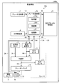
- FIG. 1 is a diagram showing a configuration example of the brake control system 30 according to the first embodiment of the present invention.
- the brake control system 30 is a system mounted on the railroad vehicle 100 and controls the brake 20 of the railroad vehicle 100.
- the brake control system 30 relays the brake command unit 1, the load-bearing device 2, the speed sensor 3, the brake control unit 4, the regenerative brake control unit 5, the electropneumatic conversion valve 6, the source air tank 7, and the relay.
- a valve 8, a pressure sensor 9, a brake cylinder 10, a pressure sensor 11, a brake shoe 12, and a wheel 13 are provided.
- the brake 20 is composed of an electropneumatic conversion valve 6, a source air tank 7, a relay valve 8, a pressure sensor 9, a brake cylinder 10, a pressure sensor 11, and a brake shoe 12.
- the railway vehicle 100 actually includes a plurality of speed sensors 3, a brake control unit 4, wheels 13, and a brake 20. Further, when a train is formed by a plurality of railroad cars 100, some configurations such as the brake command unit 1 may be mounted only on a specific railroad car such as a leading car and a trailing car of the train.
- the brake command unit 1 is installed in a driver's cab (not shown) of the railway vehicle 100, and generates a brake command 1A indicating the control content of the regenerative brake (not shown) controlled via the brake 20 and the regenerative brake control unit 5. Output.
- the control content of the brake 20 is, for example, a control for operating the brake 20, a control for releasing the brake 20, and the like.
- the control content of the regenerative brake is, for example, a control for operating the regenerative brake, a control for releasing the regenerative brake, and the like.
- the control for operating the brake 20 and the regenerative brake is a control for decelerating the railway vehicle 100, that is, a control for applying the brake.
- the control for releasing the brake 20 and the regenerative brake is a control for increasing the speed of the railway vehicle 100, that is, a control for releasing the brake.
- the brake command 1A may not specify the brake 20 or the regenerative brake.
- the brake command unit 1 may receive an operation from a driver or the like and generate a brake command 1A according to the received operation content.
- the load-bearing device 2 uses an air spring pressure sensor or the like (not shown) to generate and output a load-bearing signal 2A indicating the pressure applied to the railway vehicle 100 by a passenger or the like.
- the speed sensor 3 is a sensor that generates and outputs a speed signal 3A indicating the speed of the railroad vehicle 100 based on the rotation speed of the wheels 13. Although omitted in FIG. 1, the speed sensor 3 is installed on the bogies in front of and behind the railroad vehicle 100, and the railroad car 100 can detect the speed from each wheel 13.
- the brake control unit 4 is a brake control device that presses a brake shoe 12 against a wheel 13 and generates a braking force by the brake 20 in a railroad vehicle 100. Further, the brake control unit 4 generates a braking force by a regenerative brake (not shown) via the regenerative brake control unit 5.
- the brake control unit 4 includes an acquisition unit 41, a control unit 42, and a storage unit 43.
- the acquisition unit 41 acquires the brake command 1A from the brake command unit 1, acquires the load response signal 2A from the load response device 2, and acquires the speed signal 3A from the speed sensor 3. Further, the acquisition unit 41 acquires the regenerative feedback signal 5A from the regenerative brake control unit 5, and issues an AC (Air Control) pressure feedback command 9A, which is the command pressure of the air signal 6A of the electropneumatic conversion valve 6, from the pressure sensor 9.
- the feedback command 11A of BC (Brake Cylinder) pressure which is the brake cylinder pressure 8A of the relay valve 8, is acquired from the pressure sensor 11.
- the acquisition unit 41 outputs each acquired command and each signal to the control unit 42.
- the control unit 42 calculates a required or desired braking force for the railway vehicle 100 based on the brake command 1A, the load-bearing signal 2A, and the speed signal 3A, and a regeneration pattern indicating the desired braking force for the railway vehicle 100. Output signal 4A.
- the control unit 42 generates and outputs a pressure control signal 4B having the value obtained by subtracting the value of the regenerative feedback signal 5A from the desired braking force on the railroad vehicle 100 as the air control supplement amount. Further, the control unit 42 suppresses the mirroring of the tread of the wheel 13, and controls to eliminate the mirroring of the tread of the wheel 13 when the tread of the wheel 13 is mirrored.
- the storage unit 43 is used when the control unit 42 suppresses the mirroring of the tread of the wheel 13 and controls to eliminate the mirroring of the tread of the wheel 13 when the tread of the wheel 13 is mirrored. , The period in which each pressure is applied to the brake shoes 12, the speed of the railroad vehicle 100, and other parameters are stored.
- the regenerative brake control unit 5 calculates the actual regenerative braking force according to the actual torque based on the regenerative pattern signal 4A acquired from the brake control unit 4, and controls the regenerative braking by a drive device (not shown) or the like.
- the regenerative brake control unit 5 generates a regenerative feedback signal 5A indicating an actual regenerative braking force, which is an actual regenerative braking force, and outputs the regenerative feedback signal 5A to the brake control unit 4.
- the individual brake 20 and the regenerative brake, or the brake 20 and the regenerative brake may be collectively referred to as a brake.
- the electropneumatic conversion valve 6 converts the control signal of the pressure control signal 4B, which is an electric signal output from the control unit 42 of the brake control unit 4, into an air signal 6A indicating the control content by the air pressure.
- the original air tank 7 is an air tank that outputs compressed air 7A, which is stored compressed air.
- the relay valve 8 outputs compressed air 7A corresponding to the command pressure which is the air pressure of the air signal 6A output from the electropneumatic conversion valve 6, so that the air has a brake cylinder pressure 8A corresponding to the command pressure of the air signal 6A. Is output to the brake cylinder 10.
- the brake cylinder pressure 8A is an air signal 6A amplified by compressed air 7A. It is assumed that the brake cylinder pressure 8A and the command pressure of the air signal 6A are in a proportional relationship.
- the pressure sensor 9 is a sensor that detects the command pressure, which is the air pressure of the air signal 6A.
- the command pressure is a physical quantity indicating a force that presses the brake shoe 12 against the wheel 13.
- the pressure sensor 9 returns the command pressure of the detected air signal 6A to the brake control unit 4 as a feedback command 9A.
- the brake cylinder 10 presses the brake shoe 12 against the wheel 13 by the brake cylinder pressure 8A.
- the pressure sensor 11 is a sensor that detects the brake cylinder pressure 8A, which is the air pressure of the brake cylinder 10.
- the brake cylinder pressure 8A is a physical quantity indicating a force that presses the brake shoe 12 against the wheel 13.
- the pressure sensor 11 returns the detected brake cylinder pressure 8A to the brake control unit 4 as a feedback command 11A.
- the brake shoe 12 has a friction coefficient.
- the brake shoe 12 is pressed against the wheel 13 by the brake cylinder 10 to generate a braking force, that is, a braking force.
- the braking force of the brake 20 in the brake control system 30 can be calculated by the product of the friction coefficient of the brake shoe 12 and the brake cylinder pressure 8A.
- the wheel 13 generates a braking force, that is, a braking force by pressing the brake shoe 12 by the brake cylinder 10.
- the brake control system 30 presses the brake shoes 12 against the wheels 13 while the speed of the railroad vehicle 100 is traveling at the specified first speed or higher while the brake command 1A is generated.
- the operation of the brake 20 and the regenerative brake control unit 5 is controlled so that the cumulative period of the period is equal to or longer than the specified period.
- the brake control system 30 secures a period during which the brake shoe 12 is pressed against the wheel 13 for a specified period or longer even when the tread surface of the wheel 13 is mirrored by applying the initial loading pressure to the brake shoe 12 during regenerative braking. By doing so, the tread surface of the wheel 13 can be roughened by the brake shoe 12 to eliminate the mirroring.
- the above-mentioned first speed is set to such a speed that the mirroring of the tread surface of the wheel 13 can be eliminated when the tread surface of the wheel 13 is pressed by the brake shoe 12.
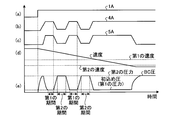
- FIG. 2 is a diagram showing an operating state of each brake when the brake control unit 4 does not perform the specific brake control of the present embodiment in the brake control system 30 according to the first embodiment.
- the control unit 42 actually controls as described above, but the brake control unit 4 will be mainly described. The same shall apply to the subsequent embodiments.
- FIG. 2A shows a brake command 1A output from the brake command unit 1 to the brake control unit 4.
- the brake command 1A is H (high)
- the control for operating at least one of the brake 20 and the regenerative brake control unit 5 is shown
- the brake command 1A is L (low)
- the brake is applied. 20 and the control which does not act on the regenerative brake control unit 5 are shown.
- FIG. 2B shows a regenerative pattern signal 4A output from the brake control unit 4 to the regenerative brake control unit 5.
- FIG. 2C shows a regenerative feedback signal 5A output from the regenerative brake control unit 5 to the brake control unit 4.
- FIG. 2D shows the speed of the railway vehicle 100 indicated by the speed signal 3A output from the speed sensor 3 to the brake control unit 4.
- the speed of the railroad vehicle 100 gradually decreases and then reaches a constant speed. This is a state in which the railroad vehicle 100 is stopped, that is, the speed of the railroad vehicle 100 becomes zero. It shall represent the state.
- FIG. 2E shows the BC pressure, which is the brake cylinder pressure 8A of the relay valve 8 indicated by the feedback command 11A output from the pressure sensor 11 to the brake control unit 4.
- the brake control unit 4 decelerates the running railway vehicle 100 by the regenerative brake controlled by the regenerative brake control unit 5.
- the brake control unit 4 acquires the brake command 1A from the brake command unit 1, outputs the regenerative pattern signal 4A to the regenerative brake control unit 5, and regenerates the feedback signal from the regenerative brake control unit 5. It takes time to acquire 5A. That is, it takes time for the brake control unit 4 to obtain a desired braking force by the regenerative brake after acquiring the brake command 1A. Therefore, the brake control unit 4 decelerates the railway vehicle 100 by the braking force of the responsive brake 20 until a desired braking force is obtained by the regenerative braking.
- the brake control unit 4 weakens the braking force by the brake 20, that is, lowers the BC pressure which is the brake cylinder pressure 8A.
- the brake control unit 4 applies an initial loading pressure to the brake shoe 12, which is a pressure such that the brake shoe 12 touches the wheel 13, so that the brake 20 can be applied immediately. That is, the brake control unit 4 sets the BC pressure, which is the brake cylinder pressure 8A, as the initial filling pressure.
- the initial filling pressure may be referred to as the first pressure.
- the brake control unit 4 applies the initial loading pressure to the brake shoe 12 while obtaining the braking force by the regenerative brake. Since the brake shoe 12 slightly touches the tread surface of the wheel 13, the tread surface of the wheel 13 may be polished by the brake shoe 12 and mirrored.
- FIG. 3 is a diagram showing an operating state of each brake when the brake control unit 4 performs the specific brake control of the present embodiment in the brake control system 30 according to the first embodiment.
- each item of FIGS. 3 (a) to 3 (e) is the same as each item of FIGS. 2 (a) to 2 (e) of FIG. 2 described above.
- the brake control unit 4 has a regeneration pattern when the speed of the railroad vehicle 100 is equal to or higher than the first speed and the period in which the brake shoes 12 are initially loaded is the first period.
- the regenerative feedback signal 5A from the regenerative brake control unit 5 is reduced, and the braking force due to the regenerative brake is reduced.
- the brake control unit 4 increases the BC pressure, which is the brake cylinder pressure 8A, in order to increase the braking force by the brake 20 by the amount that the braking force by the regenerative brake is reduced so that the desired braking force can be obtained in the railway vehicle 100. ..
- the brake control unit 4 returns the BC pressure to the initial filling pressure when the period after the BC pressure, which is the brake cylinder pressure 8A, becomes a pressure equal to or higher than the second pressure becomes the second period.
- the second pressure is a pressure large enough to decelerate the railway vehicle 100.
- the second pressure is the initial filling pressure, that is, a pressure larger than the first pressure.
- the brake control unit 4 repeatedly controls to change the BC pressure as described above while the speed of the railway vehicle 100 is equal to or higher than the first speed.
- the brake control unit 4 has a braking force that is a combination of a first braking force, which is a braking force obtained by pressing the brake shoes 12 against the wheels 13, and a second braking force, which is a braking force obtained by a regenerative brake (not shown).
- the first braking force and the second braking force are controlled so that That is, the brake control unit 4 controls the brake 20 so that the combined braking force of the first braking force and the second braking force becomes a desired braking force, and the brake control unit 4 controls the brake 20 via the regenerative brake control unit 5. Control the regenerative brake.
- the brake control unit 4 can suppress the mirroring of the tread surface of the wheel 13 by reducing the time during which the initial loading pressure is applied to the brake shoe 12. Further, the brake control unit 4 makes the period during which the brake shoe 12 is pressed against the wheel 13 by a pressure equal to or higher than the second pressure longer than the specified period as compared with the brake control shown in FIG. Therefore, the mirrored surface of the wheel 13 can be roughened to eliminate the mirrored surface.
- FIG. 4 is a flowchart showing the operation of the brake control unit 4 according to the first embodiment.
- the brake control unit 4 determines whether or not the brake command 1A has been acquired from the brake command unit 1 (step S101). When the brake command unit 4 has not acquired the brake command 1A from the brake command unit 1 (step S101: No), the brake control unit 4 waits until the brake command 1A is acquired from the brake command unit 1. When the brake command 1A is acquired from the brake command unit 1 (step S101: Yes), the brake control unit 4 controls so that the brake force is obtained by the brake 20. Specifically, the brake control unit 4 controls the brake shoe 12 so that a pressure equal to or higher than the second pressure is applied, that is, the BC pressure becomes a pressure equal to or higher than the second pressure (step S102).
- the brake control unit 4 controls the regenerative brake control unit 5 to determine whether or not a desired braking force can be obtained by the regenerative brake (step S103).
- the desired braking force is a required braking force for the railway vehicle 100 calculated by the brake control unit 4.
- the brake control unit 4 waits until the desired braking force is obtained by the regenerative brake.
- the brake control unit 4 applies the first pressure, which is the initial filling pressure, to the brake shoe 12, that is, the BC pressure is the initial filling pressure. (Step S104).
- the brake control unit 4 determines whether or not the speed of the railway vehicle 100 is equal to or higher than the first speed (step S105). When the speed of the railroad vehicle 100 is equal to or higher than the first speed (step S105: Yes), the brake control unit 4 determines whether or not the first period has elapsed since the BC pressure was set to the initial filling pressure (step S106). ). If the first period has not elapsed since the BC pressure was set to the initial loading pressure (step S106: No), the brake control unit 4 waits until the first period elapses after the BC pressure is set to the initial filling pressure.
- the brake control unit 4 lowers the regenerative pattern signal 4A, that is, lowers the regenerative braking force due to the regenerative brake (step S107). ).
- the brake control unit 4 controls the brake shoe 12 so that a pressure equal to or higher than the second pressure is applied, that is, the BC pressure becomes a pressure equal to or higher than the second pressure (step S108).
- the brake control unit 4 determines whether or not a second period has elapsed since the BC pressure was set to a pressure equal to or higher than the second pressure (step S109). When the second period has not elapsed since the BC pressure was set to the pressure equal to or higher than the second pressure (step S109: No), the brake control unit 4 sets the BC pressure to the pressure equal to or higher than the second pressure and then sets the BC pressure to the second pressure or higher. Wait until the period of When the second period elapses after the BC pressure is set to the pressure equal to or higher than the second pressure (step S109: Yes), the brake control unit 4 releases the decrease in the regenerative pattern signal 4A, that is, the regenerative braking force due to the regenerative brake. The drop is released (step S110).
- the brake control unit 4 controls the brake shoe 12 so that the first pressure, which is the initial loading pressure, is applied, that is, the BC pressure becomes the initial filling pressure (step S111).
- the brake control unit 4 returns to step S105 and repeats the above-described operation when the speed of the railway vehicle 100 is equal to or higher than the first speed (step S105: Yes).
- step S105 When the speed of the railroad vehicle 100 is less than the first speed (step S105: No), the brake control unit 4 determines whether or not the speed of the railroad vehicle 100 is equal to or higher than the second speed slower than the first speed. (Step S112).
- the second speed is a speed for determining that the brake control unit 4 shifts to the operation of stopping the railway vehicle 100.
- step S112: Yes the brake control unit 4 waits until the speed of the railroad vehicle 100 becomes less than the second speed.
- step S112: No the brake control unit 4 reduces the regenerative braking force by the regenerative brake (step S113).
- the brake control unit 4 controls the brake shoe 12 so that a pressure equal to or higher than the second pressure is applied, that is, the BC pressure becomes a pressure equal to or higher than the second pressure (step S114).
- step S105: Yes the brake control unit 4 eliminates the mirroring of the treads of the wheels 13 by the operations of steps S106 to S111.
- the brake control unit 4 controls the brake shoes 12 to be pressed against the wheels 13 at a pressure equal to or higher than the second pressure a plurality of times. Brake control is performed so that the cumulative period of the plurality of periods in which the brake shoes 12 are pressed against the wheels 13 with a pressure higher than the pressure is equal to or longer than the specified period. Specifically, when the period in which the first pressure, which is the initial loading pressure, is applied to the brake shoe 12 becomes the first period, the brake control unit 4 applies the pressure applied to the brake shoe 12 to the first pressure. The brake shoe 12 is pressed against the wheel 13 with a pressure equal to or higher than the second pressure.
- the brake control unit 4 applies the pressure to the brake shoe 12 from the pressure equal to or higher than the second pressure.
- Change to the first pressure which is the initial filling pressure.
- the brake control unit 4 repeats the above control while the speed of the railway vehicle 100 is equal to or higher than the first speed.
- the brake control unit 4 acquires the speed signal 3A from the speed sensor 3, acquires the brake command 1A from the brake command unit 1, acquires the load response signal 2A from the load receiving device 2, and obtains each of the acquired signals.
- the desired braking force is calculated based on the signal, and the brake is controlled. Therefore, when the brake control unit 4 performs the brake control as shown in FIG. 3, the BC pressure becomes a pressure equal to or higher than the second pressure when the speed of the railroad vehicle 100 is equal to or higher than the first speed. It is possible to control the length of each period, i.e. the first period and the second period, so that the cumulative period of the periods is greater than or equal to the specified period.
- the brake control unit 4 may change the order of steps S105 and S106. Further, the brake control unit 4 may change the order of step S107 and step S108. That is, the brake control unit 4 may reduce the braking force of the regenerative brake and then increase the braking force of the brake 20, or may increase the braking force of the brake 20 and then decrease the braking force of the regenerative brake.
- the brake control unit 4 determines whether or not the first period has elapsed since the BC pressure was set to the initial filling pressure in step S106, the BC pressure is not exactly the initial filling pressure, but the BC pressure is BC. If the pressure is within the specified range including the initial charge pressure, BC pressure may be regarded as the initial charge pressure. Further, comparing FIGS. 2 and 3, the brake control unit 4 performs the brake control according to the present embodiment, that is, the operation of setting the BC pressure to the initial filling pressure and then setting the BC pressure to a pressure equal to or higher than the second pressure twice. However, the brake control may be performed a specified number of times or more after the BC pressure is set to the initial filling pressure and then to a pressure equal to or higher than the second pressure. In this case, in the brake control unit 4, the storage unit 43 stores the number of times specified as a parameter.
- the brake control unit 4 may change the first period and the second period according to, for example, the speed of the railroad vehicle 100, instead of a fixed value.
- the storage unit 43 stores the first pressure, the second pressure, the first period, the second period, the first speed, the second speed, and the like as parameters.
- a calculation formula capable of calculating the first period and the second period according to the speed of the railroad vehicle 100 is stored.
- the control unit 42 calculates the first period and the second period by using the calculation formula stored in the storage unit 43.
- the brake control unit 4 may always perform the brake control shown in FIGS. 3 and 4 during the operation of the railway vehicle 100, or may perform the brake control under specified conditions.
- the brake control unit 4 may perform the brake control shown in FIGS. 3 and 4 to deteriorate the riding comfort of passengers. Therefore, the brake control unit 4 may perform brake control only once after the power of the railroad vehicle 100 is turned on, as a condition defined in consideration of the ride comfort of the passengers, or the railroad vehicle 100 is operated. Brake control may be performed when the vehicle is not forwarded.
- the railway vehicle 100 is omitted in FIG. 1, one vehicle generally includes a plurality of bogies. Further, a train formed by a plurality of railroad vehicles 100 will be provided with more bogies. Therefore, the brake control unit 4 may perform the brake control shown in FIGS. 3 and 4 for each bogie included in the railway vehicle 100.
- the brake control unit 4 is realized by a processing circuit.
- the processing circuit may be a processor and memory for executing a program stored in the memory, or may be dedicated hardware.
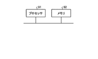
- FIG. 5 is a diagram showing an example in which the processing circuit included in the brake control system 30 according to the first embodiment is configured by a processor and a memory.
- the processing circuit is composed of the processor 91 and the memory 92, each function of the processing circuit of the brake control system 30 is realized by software, firmware, or a combination of software and firmware.
- the software or firmware is written as a program and stored in the memory 92.
- each function is realized by the processor 91 reading and executing the program stored in the memory 92. That is, the processing circuit includes a memory 92 for storing a program in which the processing of the brake control system 30 is eventually executed. It can also be said that these programs cause the computer to execute the procedures and methods of the brake control system 30.
- the processor 91 may be a CPU (Central Processing Unit), a processing device, an arithmetic unit, a microprocessor, a microcomputer, a DSP (Digital Signal Processor), or the like.
- the memory 92 includes, for example, non-volatile or volatile such as RAM (Random Access Memory), ROM (Read Only Memory), flash memory, EPROM (Erasable Programmable ROM), and EPROM (registered trademark) (Electrically EPROM).
- RAM Random Access Memory
- ROM Read Only Memory
- flash memory EPROM (Erasable Programmable ROM), and EPROM (registered trademark) (Electrically EPROM).
- Semiconductor memory magnetic disk, flexible disk, optical disk, compact disk, mini disk, DVD (Digital Versatile Disc), etc. are applicable.
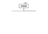
- FIG. 6 is a diagram showing an example in which the processing circuit included in the brake control system 30 according to the first embodiment is configured by dedicated hardware.
- the processing circuit is composed of dedicated hardware
- the processing circuit 93 shown in FIG. 6 includes, for example, a single circuit, a composite circuit, a programmed processor, a parallel programmed processor, an ASIC (Application Specific Integrated Circuit), and the like. FPGA (Field Programmable Gate Array) or a combination of these is applicable.
- Each function of the brake control system 30 may be realized by the processing circuit 93 for each function, or each function may be collectively realized by the processing circuit 93.
- the functions of the brake control system 30 may be realized by dedicated hardware, and some may be realized by software or firmware.
- the processing circuit can realize each of the above-mentioned functions by the dedicated hardware, software, firmware, or a combination thereof.
- the brake control unit 4 applies a first pressure that does not give braking force to at least the wheels 13 while acquiring the brake command 1A. Apply to the brake shoe 12.
- the brake control unit 4 is accumulating a period during which the brake shoes 12 are pressed against the wheels 13 with a pressure equal to or higher than the second pressure higher than the first pressure. It was decided to perform brake control for pressing the brake shoes 12 against the wheels 13 so that the above period would be longer than the specified period.
- the brake control unit 4 can suppress the mirroring of the treads of the wheels 13 of the railway vehicle 100, and can eliminate the mirroring even when the treads of the wheels 13 of the railway vehicle 100 are mirrored.
- the brake control unit 4 can suppress the mirroring of the tread surface of the wheel 13 of the railway vehicle 100 without impairing the responsiveness to the brake command 1A.
- Embodiment 2 when the speed of the railroad vehicle 100 is equal to or higher than the first speed, the brake control unit 4 applies a pressure equal to or higher than the second pressure to the brake shoes 12 and presses them against the wheels 13 a plurality of times. , The cumulative period of the second period in which the brake shoe 12 is pressed against the wheel 13 by applying a pressure equal to or higher than the second pressure is set to be equal to or longer than the specified period. In the second embodiment, when the speed of the railroad vehicle 100 is equal to or higher than the first speed, the brake control unit 4 applies a pressure equal to or higher than the second pressure to the brake shoes 12 and presses the brake shoes 12 against the wheels 13 once. The length of one second period in which the brake shoe 12 is pressed against the wheel 13 by applying a pressure equal to or higher than the second pressure is set to be equal to or longer than the specified period.
- the configuration of the railroad vehicle 100 and the brake control system 30 is the same as the configuration of the railroad vehicle 100 and the brake control system 30 in the first embodiment shown in FIG.
- FIG. 7 is a diagram showing an operating state of each brake when the brake control unit 4 performs the specific brake control of the present embodiment in the brake control system 30 according to the second embodiment.
- each item of FIGS. 7 (a) to 7 (e) is the same as each item of FIGS. 3 (a) to 3 (e) of FIG. 3 described above.
- the brake control unit 4 when the brake control unit 4 first controls the brake 20 after acquiring the brake command 1A, when the speed of the railroad vehicle 100 is equal to or higher than the first speed, it is defined as a second period.
- the brake shoe 12 is pressed against the wheel 13 with a pressure equal to or higher than the second pressure for a length equal to or longer than the second pressure.
- the subsequent operations are the same as the operations shown in the operating state of FIG.
- the brake control unit 4 decelerates the railroad vehicle 100 by the braking force of the responsive brake 20 until the braking force of the regenerative brake is obtained. At this time, the brake control unit 4 decelerates the railway vehicle 100 for a period specified as the second period or longer.
- the brake shoe 12 is pressed against the wheel 13 with a pressure equal to or higher than the second pressure.
- FIG. 8 is a flowchart showing the operation of the brake control unit 4 according to the second embodiment.
- the brake control unit 4 determines whether or not the brake command 1A has been acquired from the brake command unit 1 (step S201). When the brake command unit 4 has not acquired the brake command 1A from the brake command unit 1 (step S201: No), the brake control unit 4 waits until the brake command 1A is acquired from the brake command unit 1. When the brake command 1A is acquired from the brake command unit 1 (step S201: Yes), the brake control unit 4 controls so that the brake force is obtained by the brake 20. Specifically, the brake control unit 4 controls the brake shoe 12 so that a pressure equal to or higher than the second pressure is applied, that is, the BC pressure becomes a pressure equal to or higher than the second pressure (step S202).
- the brake control unit 4 determines whether or not the speed of the railway vehicle 100 is equal to or higher than the first speed (step S203). When the speed of the railroad vehicle 100 is less than the first speed (step S203: No), the brake control unit 4 ends the operation. When the speed of the railroad vehicle 100 is equal to or higher than the first speed (step S203: Yes), the brake control unit 4 determines whether or not a second period has elapsed since the BC pressure was changed to the pressure equal to or higher than the second pressure. (Step S204).
- step S204: No When the second period has not elapsed since the BC pressure was set to the pressure equal to or higher than the second pressure (step S204: No), the brake control unit 4 sets the BC pressure to the pressure equal to or higher than the second pressure and then sets the BC pressure to the second pressure or higher. Wait until the period of When the second period elapses after the BC pressure is set to the pressure equal to or higher than the second pressure (step S204: Yes), the brake control unit 4 controls the regenerative brake control unit 5 to obtain a desired braking force by the regenerative brake. Is determined (step S205).
- step S205: No When the desired braking force is not obtained by the regenerative brake (step S205: No), the brake control unit 4 waits until the desired braking force is obtained by the regenerative brake.
- step S205: Yes the brake control unit 4 applies the first pressure, which is the initial filling pressure, to the brake shoe 12, that is, the BC pressure is the initial filling pressure.
- step S207 The brake control unit 4 determines whether or not the speed of the railway vehicle 100 is equal to or higher than the second speed, which is slower than the first speed (step S207). When the speed of the railroad vehicle 100 is equal to or higher than the second speed (step S207: Yes), the brake control unit 4 waits until the speed of the railroad vehicle 100 becomes less than the second speed.
- step S207 When the speed of the railroad vehicle 100 is less than the second speed (step S207: No), the brake control unit 4 reduces the regenerative braking force by the regenerative brake (step S208).
- the brake control unit 4 controls the brake shoe 12 so that a pressure equal to or higher than the second pressure is applied, that is, the BC pressure becomes a pressure equal to or higher than the second pressure (step S209).
- the brake control unit 4 presses the brake shoe 12 against the wheel 13 once for a period specified by the pressure equal to or higher than the second pressure when the speed of the railroad vehicle 100 is equal to or higher than the first speed. Take control.
- the brake control unit 4 acquires the speed signal 3A from the speed sensor 3, acquires the brake command 1A from the brake command unit 1, acquires the load response signal 2A from the load receiving device 2, and obtains each of the acquired signals.
- the desired braking force is calculated based on the signal, and the brake is controlled. Therefore, when the brake control unit 4 performs the control as shown in FIG. 7, it is a period during which the BC pressure becomes the pressure equal to or higher than the second pressure when the speed of the railway vehicle 100 is equal to or higher than the first speed. It is possible to control the period of 2 to be greater than or equal to the specified period.
- the brake control unit 4 may always perform the brake control shown in FIGS. 7 and 8 during the operation of the railway vehicle 100, or the power of the railway vehicle 100 may be turned on as in the first embodiment. It may be performed only once later, or it may be performed when the railway vehicle 100 is not in operation. Further, the brake control unit 4 may perform the brake control shown in FIGS. 7 and 8 for each bogie included in the railway vehicle 100.
- the brake control unit 4 performs a second pressure or higher when the speed of the railroad vehicle 100 is equal to or higher than the first speed as brake control. It was decided to press the brake shoe 12 once against the wheel 13 for a period specified by the pressure of. Even in this case, the brake control unit 4 can obtain the same effect as that of the first embodiment.
- the brake control unit 4 can select the brake control of the first embodiment or the brake control of the second embodiment according to the effect obtained. Therefore, the brake control unit 4 performs the brake control of the first embodiment when it is important to increase the number of times the brake shoe 12 is pressed against the wheel 13, and the period per time when the brake shoe 12 is pressed against the wheel 13. When it is important to lengthen the brakes, the brake control of the second embodiment may be performed.
- the brake control unit 4 may always perform the brake control shown in FIGS. 3 and 4 or 7 and 8 during the operation of the railway vehicle 100, or the power source of the railway vehicle 100. It may be performed only the first time after the introduction, or it may be performed during the forwarding when the railway vehicle 100 is not in operation. In the third embodiment, the brake control unit 4 performs brake control when it detects that the tread surface of the wheel 13 is mirrored.
- FIG. 9 is a diagram showing a configuration example of the brake control system 30a according to the third embodiment.
- the brake control system 30a is a system mounted on the railway vehicle 100a and controls the brake 20 of the railway vehicle 100a.
- the brake control system 30a relays the brake command unit 1, the load-bearing device 2, the speed sensor 3, the brake control unit 4a, the regenerative brake control unit 5, the electropneumatic conversion valve 6, the source air tank 7, and the relay.
- a valve 8, a pressure sensor 9, a brake cylinder 10, a pressure sensor 11, a brake shoe 12, a wheel 13, and an image sensor 14 are provided.
- the image sensor 14 is a sensor that detects the state of the tread surface of the wheel 13.
- the image sensor 14 outputs the state of the tread surface of the wheel 13 to the brake control unit 4a as a detection result.
- a sensor other than the image sensor 14 for example, a vibration sensor can be used.
- the brake control unit 4a includes an acquisition unit 41a, a control unit 42a, and a storage unit 43.
- the acquisition unit 41a acquires the same signal as the acquisition unit 41 of the first and second embodiments, and further acquires the state of the tread surface of the wheel 13 from the image sensor 14.
- the control unit 42a has the same function as the control unit 42 of the first and second embodiments, and further, the tread surface of the wheel 13 is mirrored based on the state of the tread surface of the wheel 13 acquired by the acquisition unit 41a. It has a function to determine whether or not the wheel is used.
- the control unit 42a determines that the tread surface of the wheel 13 is mirrored, the control unit 42a performs the brake control described in the first embodiment or the second embodiment.
- the brake control unit 4a performs the brake control described in the first embodiment or the second embodiment based on the state of the tread surface of the wheel 13 acquired from the image sensor 14.
- FIG. 10 is a flowchart showing a determination process of whether or not to execute the brake control by the brake control unit 4a according to the third embodiment.
- the brake control unit 4a acquires the state of the tread surface of the wheel 13 from the image sensor 14 as a detection result (step S301).
- the brake control unit 4a determines whether or not the tread surface of the wheel 13 is mirrored based on the state of the tread surface of the wheel 13 acquired from the image sensor 14 (step S302).
- the brake control unit 4a determines that the tread surface of the wheel 13 is mirrored (step S302: Yes)
- the brake control unit 4a performs the brake control described in the first embodiment or the second embodiment (step S303).
- step S302: No When the brake control unit 4a determines that the tread surface of the wheel 13 is not mirrored (step S302: No), the brake control unit 4a ends the operation. In the case of step S302: No, the brake control unit 4a performs normal brake control as shown in FIG.
- the BC pressure is set to a pressure equal to or higher than the second pressure when the railway vehicle 100a is stopped, but the BC pressure. May be set to a pressure equal to or higher than the second pressure earlier than in the first and second embodiments.
- the brake control unit 4a determines that the tread surface of the wheel 13 is mirrored, the brake control unit 4a sets the BC pressure to a pressure equal to or higher than the second pressure earlier than in the first and second embodiments. The railroad vehicle 100a can be reliably stopped.
- the brake control unit 4a is an image sensor 14 which is a sensor for detecting the state of the tread, which is a portion of the wheel 13 on which the brake shoe 12 is pressed. Therefore, when the detection result that the tread surface of the wheel 13 is mirrored is acquired, the brake control described in the first embodiment or the second embodiment is performed. As a result, the brake control unit 4a performs the brake control described in the first embodiment or the second embodiment only when the tread surface of the wheel 13 is mirrored, so that the processing load is increased as compared with the first and second embodiments. Can be reduced.
- the configuration shown in the above-described embodiment shows an example of the content of the present invention, can be combined with another known technique, and is one of the configurations without departing from the gist of the present invention. It is also possible to omit or change the part.
Abstract
A brake control device is a brake control unit (4) that generates braking force by pressing a brake shoe (12) against a wheel (13) in a railroad car (100), the device comprising: an obtainment unit (41) that obtains a brake command (1A); and a control unit (42) that, while the brake command (1A) is being obtained, performs brake control of applying a first pressure, which at least does not apply a braking force to the wheel (13), to the brake shoe (12), and when a speed of the railroad car (100) is greater than or equal to a first speed, pressing the brake shoe (12) against the wheel (13) so that a cumulative period in which the brake shoe (12) is pressed against the wheel (13) at a pressure greater than or equal to a second pressure, which is greater than the first pressure, is greater than or equal to a specified period.
Description
本発明は、鉄道車両に搭載されるブレーキ制御装置およびブレーキ制御方法に関する。
The present invention relates to a brake control device and a brake control method mounted on a railway vehicle.
従来、鉄道車両は、複数の手段によって複数のブレーキ力を発生させ、減速する制御を行っている。具体的には、鉄道車両は、駆動装置による電制ブレーキ力と、空制ブレーキなどの空制ブレーキ力とを合わせたブレーキ力によって減速する。鉄道車両は、ブレーキ指令が発生した際に遅延なく減速することが求められている。特許文献1には、鉄道車両に搭載される空制ブレーキ装置が、零推力指令を受けたとき、実トルクが生じない程度の空気圧である初込め圧をブレーキパッドに与え、ブレーキパッドを車輪踏面に僅かに接触させる技術が開示されている。特許文献1に記載の空制ブレーキ装置は、ブレーキパッドを車輪踏面に僅かに接触させておくことで、遅延なくブレーキパッドを車輪踏面に押し付けてブレーキ力を発生させることができる。
Conventionally, railroad vehicles are controlled to generate a plurality of braking forces by a plurality of means to decelerate. Specifically, a railway vehicle decelerates by a braking force that is a combination of an electronically controlled braking force of a drive device and an air controlled braking force such as an air controlled brake. Railroad vehicles are required to decelerate without delay when a brake command is issued. According to Patent Document 1, when an air-controlled brake device mounted on a railroad vehicle receives a zero thrust command, an initial charge pressure, which is an air pressure that does not generate an actual torque, is applied to the brake pad, and the brake pad is applied to the wheel tread. The technique of slightly contacting the wheel is disclosed. In the air-controlled brake device described in Patent Document 1, by slightly contacting the brake pad with the wheel tread, the brake pad can be pressed against the wheel tread without delay to generate a braking force.
しかしながら、特許文献1に記載の空制ブレーキ装置は、鉄道車両の走行中にブレーキパッドを車輪踏面に僅かに接触させていることから、ブレーキパッドによって車輪踏面が鏡面化してしまう。そのため、鉄道車両は、高速時に空制ブレーキ装置を作用させた場合、ブレーキパッドと鏡面化した車輪踏面との間で粘着力が確保できず、レール上を滑走してしまう可能性がある、という問題があった。
However, in the air-controlled brake device described in Patent Document 1, since the brake pad is slightly in contact with the wheel tread while the railroad vehicle is traveling, the wheel tread is mirrored by the brake pad. Therefore, when the air-controlled brake device is applied at high speed, the railroad vehicle cannot secure the adhesive force between the brake pad and the mirrored wheel tread, and may slide on the rail. There was a problem.
本発明は、上記に鑑みてなされたものであって、ブレーキ指令への応答性を損なうことなく、鉄道車両の車輪の鏡面化を抑制可能なブレーキ制御装置を得ることを目的とする。
The present invention has been made in view of the above, and an object of the present invention is to obtain a brake control device capable of suppressing mirroring of wheels of a railway vehicle without impairing the responsiveness to a brake command.
上述した課題を解決し、目的を達成するために、本発明は、鉄道車両において、車輪に制輪子を押し付けて制動力を発生させるブレーキ制御装置である。ブレーキ制御装置は、ブレーキ指令を取得する取得部と、ブレーキ指令を取得している間、少なくとも車輪に制動力を与えない第1の圧力を制輪子にかけ、鉄道車両の速度が第1の速度以上のときに、第1の圧力よりも大きい第2の圧力以上の圧力で車輪に制輪子を押し付けている期間の累積期間が規定された期間以上になるように、車輪に制輪子を押し付けるブレーキ制御を行う制御部と、を備えることを特徴とする。
In order to solve the above-mentioned problems and achieve the object, the present invention is a brake control device that generates a braking force by pressing a brake shoe against a wheel in a railroad vehicle. The brake control device applies a first pressure to the brake shoe that does not give braking force to the wheels at least while acquiring the brake command and the acquisition unit that acquires the brake command, and the speed of the railroad vehicle is equal to or higher than the first speed. At this time, brake control that presses the brake shoes against the wheels so that the cumulative period of the period during which the brake shoes are pressed against the wheels with a pressure greater than the first pressure and greater than the second pressure is greater than or equal to the specified period. It is characterized by including a control unit for performing the above.
本発明によれば、ブレーキ制御装置は、ブレーキ指令への応答性を損なうことなく、鉄道車両の車輪の鏡面化を抑制できる、という効果を奏する。
According to the present invention, the brake control device has an effect that the mirroring of the wheels of a railroad vehicle can be suppressed without impairing the responsiveness to the brake command.
以下に、本発明の実施の形態に係るブレーキ制御装置およびブレーキ制御方法を図面に基づいて詳細に説明する。なお、この実施の形態によりこの発明が限定されるものではない。
The brake control device and the brake control method according to the embodiment of the present invention will be described in detail below with reference to the drawings. The present invention is not limited to this embodiment.
実施の形態1.
図1は、本発明の実施の形態1に係るブレーキ制御システム30の構成例を示す図である。ブレーキ制御システム30は、鉄道車両100に搭載され、鉄道車両100のブレーキ20を制御するシステムである。ブレーキ制御システム30は、ブレーキ指令部1と、応荷重装置2と、速度センサ3と、ブレーキ制御部4と、回生ブレーキ制御部5と、電空変換弁6と、元空気タンク7と、中継弁8と、圧力センサ9と、ブレーキシリンダ10と、圧力センサ11と、制輪子12と、車輪13と、を備える。電空変換弁6、元空気タンク7、中継弁8、圧力センサ9、ブレーキシリンダ10、圧力センサ11、および制輪子12によって、ブレーキ20が構成される。なお、鉄道車両100は、実際には、複数の速度センサ3、ブレーキ制御部4、車輪13、およびブレーキ20を備えているものとする。また、複数の鉄道車両100によって列車が編成されている場合、ブレーキ指令部1など一部の構成については、列車の先頭車両および後尾車両など、特定の鉄道車両にのみ搭載されていてもよい。Embodiment 1.
FIG. 1 is a diagram showing a configuration example of thebrake control system 30 according to the first embodiment of the present invention. The brake control system 30 is a system mounted on the railroad vehicle 100 and controls the brake 20 of the railroad vehicle 100. The brake control system 30 relays the brake command unit 1, the load-bearing device 2, the speed sensor 3, the brake control unit 4, the regenerative brake control unit 5, the electropneumatic conversion valve 6, the source air tank 7, and the relay. A valve 8, a pressure sensor 9, a brake cylinder 10, a pressure sensor 11, a brake shoe 12, and a wheel 13 are provided. The brake 20 is composed of an electropneumatic conversion valve 6, a source air tank 7, a relay valve 8, a pressure sensor 9, a brake cylinder 10, a pressure sensor 11, and a brake shoe 12. It is assumed that the railway vehicle 100 actually includes a plurality of speed sensors 3, a brake control unit 4, wheels 13, and a brake 20. Further, when a train is formed by a plurality of railroad cars 100, some configurations such as the brake command unit 1 may be mounted only on a specific railroad car such as a leading car and a trailing car of the train.
図1は、本発明の実施の形態1に係るブレーキ制御システム30の構成例を示す図である。ブレーキ制御システム30は、鉄道車両100に搭載され、鉄道車両100のブレーキ20を制御するシステムである。ブレーキ制御システム30は、ブレーキ指令部1と、応荷重装置2と、速度センサ3と、ブレーキ制御部4と、回生ブレーキ制御部5と、電空変換弁6と、元空気タンク7と、中継弁8と、圧力センサ9と、ブレーキシリンダ10と、圧力センサ11と、制輪子12と、車輪13と、を備える。電空変換弁6、元空気タンク7、中継弁8、圧力センサ9、ブレーキシリンダ10、圧力センサ11、および制輪子12によって、ブレーキ20が構成される。なお、鉄道車両100は、実際には、複数の速度センサ3、ブレーキ制御部4、車輪13、およびブレーキ20を備えているものとする。また、複数の鉄道車両100によって列車が編成されている場合、ブレーキ指令部1など一部の構成については、列車の先頭車両および後尾車両など、特定の鉄道車両にのみ搭載されていてもよい。
FIG. 1 is a diagram showing a configuration example of the
ブレーキ指令部1は、鉄道車両100の図示しない運転台などに設置され、ブレーキ20、および回生ブレーキ制御部5を介して制御される図示しない回生ブレーキの制御内容を示すブレーキ指令1Aを生成して出力する。ブレーキ20の制御内容とは、例えば、ブレーキ20を作用させる制御、ブレーキ20を解除する制御などである。回生ブレーキの制御内容とは、例えば、回生ブレーキを作用させる制御、回生ブレーキを解除する制御などである。ブレーキ20および回生ブレーキを作用させる制御は、鉄道車両100を減速させる制御、いわゆるブレーキをかける制御である。ブレーキ20および回生ブレーキを解除する制御は、鉄道車両100の速度を上げることができるようにする制御、いわゆるブレーキを緩める制御である。ブレーキ指令1Aは、ブレーキ20または回生ブレーキを特定しないものであってもよい。ブレーキ指令部1は、運転士などから操作を受け付けて、受け付けた操作内容に応じたブレーキ指令1Aを生成してもよい。
The brake command unit 1 is installed in a driver's cab (not shown) of the railway vehicle 100, and generates a brake command 1A indicating the control content of the regenerative brake (not shown) controlled via the brake 20 and the regenerative brake control unit 5. Output. The control content of the brake 20 is, for example, a control for operating the brake 20, a control for releasing the brake 20, and the like. The control content of the regenerative brake is, for example, a control for operating the regenerative brake, a control for releasing the regenerative brake, and the like. The control for operating the brake 20 and the regenerative brake is a control for decelerating the railway vehicle 100, that is, a control for applying the brake. The control for releasing the brake 20 and the regenerative brake is a control for increasing the speed of the railway vehicle 100, that is, a control for releasing the brake. The brake command 1A may not specify the brake 20 or the regenerative brake. The brake command unit 1 may receive an operation from a driver or the like and generate a brake command 1A according to the received operation content.
応荷重装置2は、図示しない空気ばね圧センサなどを用いて、乗客などによって鉄道車両100にかかる圧力を示す応荷重信号2Aを生成して出力する。
The load-bearing device 2 uses an air spring pressure sensor or the like (not shown) to generate and output a load-bearing signal 2A indicating the pressure applied to the railway vehicle 100 by a passenger or the like.
速度センサ3は、車輪13の回転速度に基づいて、鉄道車両100の速度を示す速度信号3Aを生成して出力するセンサである。なお、図1では省略しているが、速度センサ3は鉄道車両100の前後の台車に設置されており、鉄道車両100では、各車輪13から速度を検出することが可能である。
The speed sensor 3 is a sensor that generates and outputs a speed signal 3A indicating the speed of the railroad vehicle 100 based on the rotation speed of the wheels 13. Although omitted in FIG. 1, the speed sensor 3 is installed on the bogies in front of and behind the railroad vehicle 100, and the railroad car 100 can detect the speed from each wheel 13.
ブレーキ制御部4は、鉄道車両100において、車輪13に制輪子12を押し付けてブレーキ20で制動力を発生させるブレーキ制御装置である。また、ブレーキ制御部4は、回生ブレーキ制御部5を介して、図示しない回生ブレーキで制動力を発生させる。ブレーキ制御部4は、取得部41と、制御部42と、記憶部43と、を備える。
The brake control unit 4 is a brake control device that presses a brake shoe 12 against a wheel 13 and generates a braking force by the brake 20 in a railroad vehicle 100. Further, the brake control unit 4 generates a braking force by a regenerative brake (not shown) via the regenerative brake control unit 5. The brake control unit 4 includes an acquisition unit 41, a control unit 42, and a storage unit 43.
取得部41は、ブレーキ指令部1からブレーキ指令1Aを取得し、応荷重装置2から応荷重信号2Aを取得し、速度センサ3から速度信号3Aを取得する。また、取得部41は、回生ブレーキ制御部5から回生フィードバック信号5Aを取得し、圧力センサ9から電空変換弁6の空気信号6Aの指令圧であるAC(Air Control)圧のフィードバック指令9Aを取得し、圧力センサ11から中継弁8のブレーキシリンダ圧8AであるBC(Brake Cylinder)圧のフィードバック指令11Aを取得する。取得部41は、取得した各指令および各信号を制御部42に出力する。
The acquisition unit 41 acquires the brake command 1A from the brake command unit 1, acquires the load response signal 2A from the load response device 2, and acquires the speed signal 3A from the speed sensor 3. Further, the acquisition unit 41 acquires the regenerative feedback signal 5A from the regenerative brake control unit 5, and issues an AC (Air Control) pressure feedback command 9A, which is the command pressure of the air signal 6A of the electropneumatic conversion valve 6, from the pressure sensor 9. The feedback command 11A of BC (Brake Cylinder) pressure, which is the brake cylinder pressure 8A of the relay valve 8, is acquired from the pressure sensor 11. The acquisition unit 41 outputs each acquired command and each signal to the control unit 42.
制御部42は、ブレーキ指令1A、応荷重信号2A、および速度信号3Aに基づいて、鉄道車両100に対する必要な、すなわち所望のブレーキ力を算出し、鉄道車両100に対する所望のブレーキ力を示す回生パターン信号4Aを出力する。制御部42は、鉄道車両100に対する所望のブレーキ力から、回生フィードバック信号5Aの値を減算したものを空制補足量とする圧力制御信号4Bを生成して出力する。また、制御部42は、車輪13の踏面の鏡面化を抑制し、車輪13の踏面が鏡面化した場合に車輪13の踏面の鏡面化を解消する制御を行う。
The control unit 42 calculates a required or desired braking force for the railway vehicle 100 based on the brake command 1A, the load-bearing signal 2A, and the speed signal 3A, and a regeneration pattern indicating the desired braking force for the railway vehicle 100. Output signal 4A. The control unit 42 generates and outputs a pressure control signal 4B having the value obtained by subtracting the value of the regenerative feedback signal 5A from the desired braking force on the railroad vehicle 100 as the air control supplement amount. Further, the control unit 42 suppresses the mirroring of the tread of the wheel 13, and controls to eliminate the mirroring of the tread of the wheel 13 when the tread of the wheel 13 is mirrored.
記憶部43は、制御部42が車輪13の踏面の鏡面化を抑制し、車輪13の踏面が鏡面化した場合に車輪13の踏面の鏡面化を解消する制御を行う際に使用する、BC圧、制輪子12に各圧力をかける期間、鉄道車両100の速度などのパラメータを記憶する。
The storage unit 43 is used when the control unit 42 suppresses the mirroring of the tread of the wheel 13 and controls to eliminate the mirroring of the tread of the wheel 13 when the tread of the wheel 13 is mirrored. , The period in which each pressure is applied to the brake shoes 12, the speed of the railroad vehicle 100, and other parameters are stored.
回生ブレーキ制御部5は、ブレーキ制御部4から取得した回生パターン信号4Aに基づいて、実トルクに応じた実回生ブレーキ力を算出し、図示しない駆動装置などによる回生ブレーキを制御する。回生ブレーキ制御部5は、実際の回生ブレーキ力である実回生ブレーキ力を示す回生フィードバック信号5Aを生成してブレーキ制御部4に出力する。以降の説明において、個々のブレーキ20および回生ブレーキ、または、ブレーキ20および回生ブレーキをまとめて、単にブレーキと称することがある。
The regenerative brake control unit 5 calculates the actual regenerative braking force according to the actual torque based on the regenerative pattern signal 4A acquired from the brake control unit 4, and controls the regenerative braking by a drive device (not shown) or the like. The regenerative brake control unit 5 generates a regenerative feedback signal 5A indicating an actual regenerative braking force, which is an actual regenerative braking force, and outputs the regenerative feedback signal 5A to the brake control unit 4. In the following description, the individual brake 20 and the regenerative brake, or the brake 20 and the regenerative brake may be collectively referred to as a brake.
電空変換弁6は、ブレーキ制御部4の制御部42から出力される電気信号である圧力制御信号4Bの制御信号を、空気の圧力によって制御内容を示す空気信号6Aに変換する。
The electropneumatic conversion valve 6 converts the control signal of the pressure control signal 4B, which is an electric signal output from the control unit 42 of the brake control unit 4, into an air signal 6A indicating the control content by the air pressure.
元空気タンク7は、貯留されている圧縮された空気である圧縮空気7Aを出力する空気タンクである。
The original air tank 7 is an air tank that outputs compressed air 7A, which is stored compressed air.
中継弁8は、電空変換弁6から出力された空気信号6Aの空気圧である指令圧に応じた圧縮空気7Aを出力することにより、空気信号6Aの指令圧に応じたブレーキシリンダ圧8Aの空気をブレーキシリンダ10に出力する。ブレーキシリンダ圧8Aは、空気信号6Aが圧縮空気7Aによって増幅されたものである。ブレーキシリンダ圧8Aと空気信号6Aの指令圧とは、比例関係にあるものとする。
The relay valve 8 outputs compressed air 7A corresponding to the command pressure which is the air pressure of the air signal 6A output from the electropneumatic conversion valve 6, so that the air has a brake cylinder pressure 8A corresponding to the command pressure of the air signal 6A. Is output to the brake cylinder 10. The brake cylinder pressure 8A is an air signal 6A amplified by compressed air 7A. It is assumed that the brake cylinder pressure 8A and the command pressure of the air signal 6A are in a proportional relationship.
圧力センサ9は、空気信号6Aの空気圧である指令圧を検出するセンサである。指令圧は、車輪13に制輪子12を押し付ける力を示す物理量である。圧力センサ9は、検出した空気信号6Aの指令圧をフィードバック指令9Aとして、ブレーキ制御部4に帰還させる。
The pressure sensor 9 is a sensor that detects the command pressure, which is the air pressure of the air signal 6A. The command pressure is a physical quantity indicating a force that presses the brake shoe 12 against the wheel 13. The pressure sensor 9 returns the command pressure of the detected air signal 6A to the brake control unit 4 as a feedback command 9A.
ブレーキシリンダ10は、ブレーキシリンダ圧8Aによって、車輪13に制輪子12を押し付ける。
The brake cylinder 10 presses the brake shoe 12 against the wheel 13 by the brake cylinder pressure 8A.
圧力センサ11は、ブレーキシリンダ10の空気圧であるブレーキシリンダ圧8Aを検出するセンサである。ブレーキシリンダ圧8Aは、車輪13に制輪子12を押し付ける力を示す物理量である。圧力センサ11は、検出したブレーキシリンダ圧8Aをフィードバック指令11Aとして、ブレーキ制御部4に帰還させる。
The pressure sensor 11 is a sensor that detects the brake cylinder pressure 8A, which is the air pressure of the brake cylinder 10. The brake cylinder pressure 8A is a physical quantity indicating a force that presses the brake shoe 12 against the wheel 13. The pressure sensor 11 returns the detected brake cylinder pressure 8A to the brake control unit 4 as a feedback command 11A.
制輪子12は、摩擦係数を有している。制輪子12は、ブレーキシリンダ10によって車輪13に押し付けられることで、ブレーキ力、すなわち制動力を発生させる。ブレーキ制御システム30におけるブレーキ20のブレーキ力は、制輪子12の摩擦係数と、ブレーキシリンダ圧8Aの積によって算出することができる。
The brake shoe 12 has a friction coefficient. The brake shoe 12 is pressed against the wheel 13 by the brake cylinder 10 to generate a braking force, that is, a braking force. The braking force of the brake 20 in the brake control system 30 can be calculated by the product of the friction coefficient of the brake shoe 12 and the brake cylinder pressure 8A.
車輪13は、ブレーキシリンダ10によって制輪子12を押し付けられることで、ブレーキ力、すなわち制動力を発生させる。
The wheel 13 generates a braking force, that is, a braking force by pressing the brake shoe 12 by the brake cylinder 10.
つづいて、ブレーキ制御システム30の動作について説明する。本実施の形態において、ブレーキ制御システム30は、ブレーキ指令1Aが発生している間、鉄道車両100の速度が規定された第1の速度以上で走行中、車輪13に制輪子12を押し付けている期間の累積期間が規定された期間以上になるように、ブレーキ20および回生ブレーキ制御部5の動作を制御する。ブレーキ制御システム30は、回生ブレーキ中に制輪子12に初込め圧をかけて車輪13の踏面が鏡面化された場合でも、車輪13に制輪子12を押し付けている期間を規定された期間以上確保することで、車輪13の踏面を制輪子12で荒らして鏡面化を解消することができる。ここで、車輪13の踏面を制輪子12で荒らして鏡面化を解消する場合、鉄道車両100の速度が遅いと十分に鏡面化を解消できないことが考えられる。そのため、前述の第1の速度は、車輪13の踏面を制輪子12で押し付けたときに車輪13の踏面の鏡面化を解消できる程度の速度とする。
Next, the operation of the brake control system 30 will be described. In the present embodiment, the brake control system 30 presses the brake shoes 12 against the wheels 13 while the speed of the railroad vehicle 100 is traveling at the specified first speed or higher while the brake command 1A is generated. The operation of the brake 20 and the regenerative brake control unit 5 is controlled so that the cumulative period of the period is equal to or longer than the specified period. The brake control system 30 secures a period during which the brake shoe 12 is pressed against the wheel 13 for a specified period or longer even when the tread surface of the wheel 13 is mirrored by applying the initial loading pressure to the brake shoe 12 during regenerative braking. By doing so, the tread surface of the wheel 13 can be roughened by the brake shoe 12 to eliminate the mirroring. Here, when the tread surface of the wheel 13 is roughened by the brake shoe 12 to eliminate the mirroring, it is considered that the mirroring cannot be sufficiently eliminated if the speed of the railway vehicle 100 is slow. Therefore, the above-mentioned first speed is set to such a speed that the mirroring of the tread surface of the wheel 13 can be eliminated when the tread surface of the wheel 13 is pressed by the brake shoe 12.
ブレーキ制御システム30による各ブレーキの動作状態について説明する。図2は、実施の形態1に係るブレーキ制御システム30においてブレーキ制御部4が本実施の形態の特有のブレーキ制御を行わなかったときの各ブレーキの動作状態を示す図である。なお、ブレーキ制御部4では、実際には前述のように制御部42が制御を行っているが、ブレーキ制御部4を主体にして説明する。以降の実施の形態についても同様とする。
The operating state of each brake by the brake control system 30 will be described. FIG. 2 is a diagram showing an operating state of each brake when the brake control unit 4 does not perform the specific brake control of the present embodiment in the brake control system 30 according to the first embodiment. In the brake control unit 4, the control unit 42 actually controls as described above, but the brake control unit 4 will be mainly described. The same shall apply to the subsequent embodiments.
図2において、図2(a)は、ブレーキ指令部1からブレーキ制御部4に出力されるブレーキ指令1Aを示す。図2(a)において、ブレーキ指令1AがH(ハイ)のときがブレーキ20および回生ブレーキ制御部5のうち少なくとも1つを作用させる制御を示し、ブレーキ指令1AがL(ロー)のときがブレーキ20および回生ブレーキ制御部5を作用させない制御を示す。図2(b)は、ブレーキ制御部4から回生ブレーキ制御部5に出力される回生パターン信号4Aを示す。図2(c)は、回生ブレーキ制御部5からブレーキ制御部4に出力される回生フィードバック信号5Aを示す。図2(d)は、速度センサ3からブレーキ制御部4に出力される速度信号3Aで示される鉄道車両100の速度を示す。なお、図2(d)において鉄道車両100の速度が徐々に低下した後に一定の速度になっているが、これは、鉄道車両100が停止した状態、すなわち鉄道車両100の速度がゼロになった状態を表しているものとする。図2(e)は、圧力センサ11からブレーキ制御部4に出力されるフィードバック指令11Aで示される中継弁8のブレーキシリンダ圧8AであるBC圧を示す。
In FIG. 2, FIG. 2A shows a brake command 1A output from the brake command unit 1 to the brake control unit 4. In FIG. 2A, when the brake command 1A is H (high), the control for operating at least one of the brake 20 and the regenerative brake control unit 5 is shown, and when the brake command 1A is L (low), the brake is applied. 20 and the control which does not act on the regenerative brake control unit 5 are shown. FIG. 2B shows a regenerative pattern signal 4A output from the brake control unit 4 to the regenerative brake control unit 5. FIG. 2C shows a regenerative feedback signal 5A output from the regenerative brake control unit 5 to the brake control unit 4. FIG. 2D shows the speed of the railway vehicle 100 indicated by the speed signal 3A output from the speed sensor 3 to the brake control unit 4. In FIG. 2D, the speed of the railroad vehicle 100 gradually decreases and then reaches a constant speed. This is a state in which the railroad vehicle 100 is stopped, that is, the speed of the railroad vehicle 100 becomes zero. It shall represent the state. FIG. 2E shows the BC pressure, which is the brake cylinder pressure 8A of the relay valve 8 indicated by the feedback command 11A output from the pressure sensor 11 to the brake control unit 4.
一般的に、ブレーキ制御部4は、回生ブレーキ制御部5の制御による回生ブレーキによって走行中の鉄道車両100を減速させる。しかしながら、図2に示すように、ブレーキ制御部4が、ブレーキ指令部1からブレーキ指令1Aを取得し、回生ブレーキ制御部5に回生パターン信号4Aを出力して回生ブレーキ制御部5から回生フィードバック信号5Aを取得するまでに時間がかかる。すなわち、ブレーキ制御部4は、ブレーキ指令1Aを取得してから回生ブレーキによって所望のブレーキ力が得られるまでに時間がかかる。そのため、ブレーキ制御部4は、回生ブレーキによって所望のブレーキ力が得られるまでの間、応答性の良いブレーキ20によるブレーキ力によって鉄道車両100を減速させる。
Generally, the brake control unit 4 decelerates the running railway vehicle 100 by the regenerative brake controlled by the regenerative brake control unit 5. However, as shown in FIG. 2, the brake control unit 4 acquires the brake command 1A from the brake command unit 1, outputs the regenerative pattern signal 4A to the regenerative brake control unit 5, and regenerates the feedback signal from the regenerative brake control unit 5. It takes time to acquire 5A. That is, it takes time for the brake control unit 4 to obtain a desired braking force by the regenerative brake after acquiring the brake command 1A. Therefore, the brake control unit 4 decelerates the railway vehicle 100 by the braking force of the responsive brake 20 until a desired braking force is obtained by the regenerative braking.
その後、ブレーキ制御部4は、回生ブレーキによって所望のブレーキ力が得られると、ブレーキ20によるブレーキ力を弱める、すなわちブレーキシリンダ圧8AであるBC圧を低下させる。このとき、ブレーキ制御部4は、すぐにブレーキ20を作用させることができるように、制輪子12が車輪13に触れる程度の圧力である初込め圧を制輪子12にかけておく。すなわち、ブレーキ制御部4は、ブレーキシリンダ圧8AであるBC圧を初込め圧にする。以降の説明において、初込め圧を第1の圧力と称することがある。図2に示すように、ブレーキ制御部4は、回生ブレーキによってブレーキ力を得ている間、制輪子12に初込め圧を与えている。制輪子12が車輪13の踏面に僅かに触れていることから、車輪13の踏面は、制輪子12によって磨かれ、鏡面化してしまう可能性がある。
After that, when the desired braking force is obtained by the regenerative brake, the brake control unit 4 weakens the braking force by the brake 20, that is, lowers the BC pressure which is the brake cylinder pressure 8A. At this time, the brake control unit 4 applies an initial loading pressure to the brake shoe 12, which is a pressure such that the brake shoe 12 touches the wheel 13, so that the brake 20 can be applied immediately. That is, the brake control unit 4 sets the BC pressure, which is the brake cylinder pressure 8A, as the initial filling pressure. In the following description, the initial filling pressure may be referred to as the first pressure. As shown in FIG. 2, the brake control unit 4 applies the initial loading pressure to the brake shoe 12 while obtaining the braking force by the regenerative brake. Since the brake shoe 12 slightly touches the tread surface of the wheel 13, the tread surface of the wheel 13 may be polished by the brake shoe 12 and mirrored.
図3は、実施の形態1に係るブレーキ制御システム30においてブレーキ制御部4が本実施の形態の特有のブレーキ制御を行ったときの各ブレーキの動作状態を示す図である。図3において、図3(a)から図3(e)の各項目は、前述の図2の図2(a)から図2(e)の各項目と同様である。
FIG. 3 is a diagram showing an operating state of each brake when the brake control unit 4 performs the specific brake control of the present embodiment in the brake control system 30 according to the first embodiment. In FIG. 3, each item of FIGS. 3 (a) to 3 (e) is the same as each item of FIGS. 2 (a) to 2 (e) of FIG. 2 described above.
本実施の形態において、ブレーキ制御部4は、鉄道車両100の速度が第1の速度以上の場合、制輪子12に初込め圧をかけている期間が第1の期間になった場合、回生パターン信号4Aの出力を低下させることで、回生ブレーキ制御部5からの回生フィードバック信号5Aを低下させ、回生ブレーキによるブレーキ力を低下させる。ブレーキ制御部4は、鉄道車両100において所望のブレーキ力が得られるように、回生ブレーキによるブレーキ力が低下した分、ブレーキ20によるブレーキ力を上げるため、ブレーキシリンダ圧8AであるBC圧を大きくする。ブレーキ制御部4は、ブレーキシリンダ圧8AであるBC圧が第2の圧力以上の圧力になってからの期間が第2の期間になった場合、BC圧を初込め圧に戻す。第2の圧力は、鉄道車両100を減速させることができる大きさの圧力である。第2の圧力は、初込め圧すなわち第1の圧力よりも大きい圧力である。ブレーキ制御部4は、鉄道車両100の速度が第1の速度以上の間、上記のようにBC圧を変更する制御を繰り返し行う。
In the present embodiment, the brake control unit 4 has a regeneration pattern when the speed of the railroad vehicle 100 is equal to or higher than the first speed and the period in which the brake shoes 12 are initially loaded is the first period. By reducing the output of the signal 4A, the regenerative feedback signal 5A from the regenerative brake control unit 5 is reduced, and the braking force due to the regenerative brake is reduced. The brake control unit 4 increases the BC pressure, which is the brake cylinder pressure 8A, in order to increase the braking force by the brake 20 by the amount that the braking force by the regenerative brake is reduced so that the desired braking force can be obtained in the railway vehicle 100. .. The brake control unit 4 returns the BC pressure to the initial filling pressure when the period after the BC pressure, which is the brake cylinder pressure 8A, becomes a pressure equal to or higher than the second pressure becomes the second period. The second pressure is a pressure large enough to decelerate the railway vehicle 100. The second pressure is the initial filling pressure, that is, a pressure larger than the first pressure. The brake control unit 4 repeatedly controls to change the BC pressure as described above while the speed of the railway vehicle 100 is equal to or higher than the first speed.
ブレーキ制御部4は、車輪13に制輪子12を押し付けて得られる制動力である第1のブレーキ力と、図示しない回生ブレーキによって得られる制動力である第2のブレーキ力とを併せたブレーキ力が所望のブレーキ力になるように、第1のブレーキ力および第2のブレーキ力を制御する。すなわち、ブレーキ制御部4は、第1のブレーキ力と第2のブレーキ力とを併せたブレーキ力が所望のブレーキ力になるように、ブレーキ20を制御するとともに、回生ブレーキ制御部5を介して回生ブレーキを制御する。
The brake control unit 4 has a braking force that is a combination of a first braking force, which is a braking force obtained by pressing the brake shoes 12 against the wheels 13, and a second braking force, which is a braking force obtained by a regenerative brake (not shown). The first braking force and the second braking force are controlled so that That is, the brake control unit 4 controls the brake 20 so that the combined braking force of the first braking force and the second braking force becomes a desired braking force, and the brake control unit 4 controls the brake 20 via the regenerative brake control unit 5. Control the regenerative brake.
ブレーキ制御部4は、図2に示すブレーキ制御と比較して、制輪子12に初込め圧をかけている時間を減らすことで車輪13の踏面の鏡面化を抑制することができる。また、ブレーキ制御部4は、図2に示すブレーキ制御と比較して、第2の圧力以上の圧力によって車輪13に制輪子12を押し付けている期間が規定された期間以上になるようにすることで、鏡面化された車輪13の踏面を荒らして鏡面化を解消することができる。
Compared with the brake control shown in FIG. 2, the brake control unit 4 can suppress the mirroring of the tread surface of the wheel 13 by reducing the time during which the initial loading pressure is applied to the brake shoe 12. Further, the brake control unit 4 makes the period during which the brake shoe 12 is pressed against the wheel 13 by a pressure equal to or higher than the second pressure longer than the specified period as compared with the brake control shown in FIG. Therefore, the mirrored surface of the wheel 13 can be roughened to eliminate the mirrored surface.
ブレーキ制御部4の動作を、フローチャートを用いて説明する。図4は、実施の形態1に係るブレーキ制御部4の動作を示すフローチャートである。ブレーキ制御部4は、ブレーキ指令部1からブレーキ指令1Aを取得したか否かを判定する(ステップS101)。ブレーキ制御部4は、ブレーキ指令部1からブレーキ指令1Aを取得していない場合(ステップS101:No)、ブレーキ指令部1からブレーキ指令1Aを取得するまで待機する。ブレーキ制御部4は、ブレーキ指令部1からブレーキ指令1Aを取得した場合(ステップS101:Yes)、ブレーキ20によってブレーキ力が得られるように制御を行う。具体的には、ブレーキ制御部4は、制輪子12に第2の圧力以上の圧力がかかるように、すなわちBC圧が第2の圧力以上の圧力になるように制御する(ステップS102)。
The operation of the brake control unit 4 will be described using a flowchart. FIG. 4 is a flowchart showing the operation of the brake control unit 4 according to the first embodiment. The brake control unit 4 determines whether or not the brake command 1A has been acquired from the brake command unit 1 (step S101). When the brake command unit 4 has not acquired the brake command 1A from the brake command unit 1 (step S101: No), the brake control unit 4 waits until the brake command 1A is acquired from the brake command unit 1. When the brake command 1A is acquired from the brake command unit 1 (step S101: Yes), the brake control unit 4 controls so that the brake force is obtained by the brake 20. Specifically, the brake control unit 4 controls the brake shoe 12 so that a pressure equal to or higher than the second pressure is applied, that is, the BC pressure becomes a pressure equal to or higher than the second pressure (step S102).
ブレーキ制御部4は、回生ブレーキ制御部5を制御して、回生ブレーキによって所望のブレーキ力が得られるようになったか否かを判定する(ステップS103)。所望のブレーキ力とは、ブレーキ制御部4によって算出された鉄道車両100に対する必要なブレーキ力である。ブレーキ制御部4は、回生ブレーキによって所望のブレーキ力が得られていない場合(ステップS103:No)、回生ブレーキによって所望のブレーキ力が得られるまで待機する。ブレーキ制御部4は、回生ブレーキによって所望のブレーキ力が得られた場合(ステップS103:Yes)、制輪子12に初込め圧である第1の圧力がかかるように、すなわちBC圧が初込め圧になるように制御する(ステップS104)。
The brake control unit 4 controls the regenerative brake control unit 5 to determine whether or not a desired braking force can be obtained by the regenerative brake (step S103). The desired braking force is a required braking force for the railway vehicle 100 calculated by the brake control unit 4. When the desired braking force is not obtained by the regenerative brake (step S103: No), the brake control unit 4 waits until the desired braking force is obtained by the regenerative brake. When the desired braking force is obtained by the regenerative brake (step S103: Yes), the brake control unit 4 applies the first pressure, which is the initial filling pressure, to the brake shoe 12, that is, the BC pressure is the initial filling pressure. (Step S104).
ブレーキ制御部4は、鉄道車両100の速度が第1の速度以上か否かを判定する(ステップS105)。ブレーキ制御部4は、鉄道車両100の速度が第1の速度以上の場合(ステップS105:Yes)、BC圧を初込め圧にしてから第1の期間経過したか否かを判定する(ステップS106)。ブレーキ制御部4は、BC圧を初込め圧にしてから第1の期間経過していない場合(ステップS106:No)、BC圧を初込め圧にしてから第1の期間経過するまで待機する。ブレーキ制御部4は、BC圧を初込め圧にしてから第1の期間経過した場合(ステップS106:Yes)、回生パターン信号4Aを低下させる、すなわち回生ブレーキによる回生ブレーキ力を低下させる(ステップS107)。ブレーキ制御部4は、制輪子12に第2の圧力以上の圧力がかかるように、すなわちBC圧が第2の圧力以上の圧力になるように制御する(ステップS108)。
The brake control unit 4 determines whether or not the speed of the railway vehicle 100 is equal to or higher than the first speed (step S105). When the speed of the railroad vehicle 100 is equal to or higher than the first speed (step S105: Yes), the brake control unit 4 determines whether or not the first period has elapsed since the BC pressure was set to the initial filling pressure (step S106). ). If the first period has not elapsed since the BC pressure was set to the initial loading pressure (step S106: No), the brake control unit 4 waits until the first period elapses after the BC pressure is set to the initial filling pressure. When the first period elapses after the BC pressure is initially set to the initial filling pressure (step S106: Yes), the brake control unit 4 lowers the regenerative pattern signal 4A, that is, lowers the regenerative braking force due to the regenerative brake (step S107). ). The brake control unit 4 controls the brake shoe 12 so that a pressure equal to or higher than the second pressure is applied, that is, the BC pressure becomes a pressure equal to or higher than the second pressure (step S108).
ブレーキ制御部4は、BC圧を第2の圧力以上の圧力にしてから第2の期間経過したか否かを判定する(ステップS109)。ブレーキ制御部4は、BC圧を第2の圧力以上の圧力にしてから第2の期間経過していない場合(ステップS109:No)、BC圧を第2の圧力以上の圧力にしてから第2の期間経過するまで待機する。ブレーキ制御部4は、BC圧を第2の圧力以上の圧力にしてから第2の期間経過した場合(ステップS109:Yes)、回生パターン信号4Aの低下を解除、すなわち回生ブレーキによる回生ブレーキ力の低下を解除する(ステップS110)。ブレーキ制御部4は、制輪子12に初込め圧である第1の圧力がかかるように、すなわちBC圧が初込め圧になるように制御する(ステップS111)。ブレーキ制御部4は、ステップS105に戻って、鉄道車両100の速度が第1の速度以上の場合(ステップS105:Yes)、前述の動作を繰り返し行う。
The brake control unit 4 determines whether or not a second period has elapsed since the BC pressure was set to a pressure equal to or higher than the second pressure (step S109). When the second period has not elapsed since the BC pressure was set to the pressure equal to or higher than the second pressure (step S109: No), the brake control unit 4 sets the BC pressure to the pressure equal to or higher than the second pressure and then sets the BC pressure to the second pressure or higher. Wait until the period of When the second period elapses after the BC pressure is set to the pressure equal to or higher than the second pressure (step S109: Yes), the brake control unit 4 releases the decrease in the regenerative pattern signal 4A, that is, the regenerative braking force due to the regenerative brake. The drop is released (step S110). The brake control unit 4 controls the brake shoe 12 so that the first pressure, which is the initial loading pressure, is applied, that is, the BC pressure becomes the initial filling pressure (step S111). The brake control unit 4 returns to step S105 and repeats the above-described operation when the speed of the railway vehicle 100 is equal to or higher than the first speed (step S105: Yes).
ブレーキ制御部4は、鉄道車両100の速度が第1の速度未満の場合(ステップS105:No)、鉄道車両100の速度が、第1の速度よりも遅い第2の速度以上か否かを判定する(ステップS112)。第2の速度は、ブレーキ制御部4が鉄道車両100を停止させる動作に移行することを判定するための速度である。ブレーキ制御部4は、鉄道車両100の速度が第2の速度以上の場合(ステップS112:Yes)、鉄道車両100の速度が第2の速度未満になるまで待機する。ブレーキ制御部4は、鉄道車両100の速度が第2の速度未満の場合(ステップS112:No)、回生ブレーキによる回生ブレーキ力を低下させる(ステップS113)。ブレーキ制御部4は、制輪子12に第2の圧力以上の圧力がかかるように、すなわちBC圧が第2の圧力以上の圧力になるように制御する(ステップS114)。
When the speed of the railroad vehicle 100 is less than the first speed (step S105: No), the brake control unit 4 determines whether or not the speed of the railroad vehicle 100 is equal to or higher than the second speed slower than the first speed. (Step S112). The second speed is a speed for determining that the brake control unit 4 shifts to the operation of stopping the railway vehicle 100. When the speed of the railroad vehicle 100 is equal to or higher than the second speed (step S112: Yes), the brake control unit 4 waits until the speed of the railroad vehicle 100 becomes less than the second speed. When the speed of the railroad vehicle 100 is less than the second speed (step S112: No), the brake control unit 4 reduces the regenerative braking force by the regenerative brake (step S113). The brake control unit 4 controls the brake shoe 12 so that a pressure equal to or higher than the second pressure is applied, that is, the BC pressure becomes a pressure equal to or higher than the second pressure (step S114).
車輪13に制輪子12を押し付けて車輪13の踏面を制輪子12で荒らして車輪13の踏面の鏡面化を解消するためには、鉄道車両100の速度が一定の速度以上の状態にあることが望ましい。そのため、ブレーキ制御部4は、鉄道車両100の速度が第1の速度以上の場合(ステップS105:Yes)、ステップS106からステップS111の動作によって、車輪13の踏面の鏡面化を解消する。
In order to press the brake shoes 12 against the wheels 13 and roughen the treads of the wheels 13 with the brake shoes 12 to eliminate the mirroring of the treads of the wheels 13, the speed of the railroad vehicle 100 must be at a certain speed or higher. desirable. Therefore, when the speed of the railroad vehicle 100 is equal to or higher than the first speed (step S105: Yes), the brake control unit 4 eliminates the mirroring of the treads of the wheels 13 by the operations of steps S106 to S111.
このように、ブレーキ制御部4は、鉄道車両100の速度が第1の速度以上のときに、第2の圧力以上の圧力で車輪13に制輪子12を押し付ける制御を複数回行い、第2の圧力の以上の圧力で車輪13に制輪子12を押し付けている複数の期間の累積期間が規定された期間以上になるようブレーキ制御を行う。具体的には、ブレーキ制御部4は、制輪子12に初込め圧である第1の圧力をかけている期間が第1の期間になった場合、制輪子12にかける圧力を第1の圧力から第2の圧力以上の圧力に変更して第2の圧力以上の圧力で車輪13に制輪子12を押し付ける。ブレーキ制御部4は、第2の圧力以上の圧力で車輪13に制輪子12を押し付けている期間が第2の期間になった場合、制輪子12にかける圧力を第2の圧力以上の圧力から初込め圧である第1の圧力に変更する。ブレーキ制御部4は、鉄道車両100の速度が第1の速度以上の間、上記の制御を繰り返し行う。
In this way, when the speed of the railroad vehicle 100 is equal to or higher than the first speed, the brake control unit 4 controls the brake shoes 12 to be pressed against the wheels 13 at a pressure equal to or higher than the second pressure a plurality of times. Brake control is performed so that the cumulative period of the plurality of periods in which the brake shoes 12 are pressed against the wheels 13 with a pressure higher than the pressure is equal to or longer than the specified period. Specifically, when the period in which the first pressure, which is the initial loading pressure, is applied to the brake shoe 12 becomes the first period, the brake control unit 4 applies the pressure applied to the brake shoe 12 to the first pressure. The brake shoe 12 is pressed against the wheel 13 with a pressure equal to or higher than the second pressure. When the period in which the brake shoe 12 is pressed against the wheel 13 with a pressure equal to or higher than the second pressure becomes the second period, the brake control unit 4 applies the pressure to the brake shoe 12 from the pressure equal to or higher than the second pressure. Change to the first pressure, which is the initial filling pressure. The brake control unit 4 repeats the above control while the speed of the railway vehicle 100 is equal to or higher than the first speed.
ブレーキ制御部4は、前述のように、速度センサ3から速度信号3Aを取得し、ブレーキ指令部1からブレーキ指令1Aを取得し、応荷重装置2から応荷重信号2Aを取得し、取得した各信号に基づいて所望のブレーキ力を算出し、ブレーキ制御を行う。そのため、ブレーキ制御部4は、図3に示すようなブレーキ制御を行う場合において、鉄道車両100の速度が第1の速度以上のときにBC圧が第2の圧力以上の圧力になる第2の期間の累積期間が規定された期間以上になるように、各期間すなわち第1の期間および第2の期間の長さを制御することが可能である。
As described above, the brake control unit 4 acquires the speed signal 3A from the speed sensor 3, acquires the brake command 1A from the brake command unit 1, acquires the load response signal 2A from the load receiving device 2, and obtains each of the acquired signals. The desired braking force is calculated based on the signal, and the brake is controlled. Therefore, when the brake control unit 4 performs the brake control as shown in FIG. 3, the BC pressure becomes a pressure equal to or higher than the second pressure when the speed of the railroad vehicle 100 is equal to or higher than the first speed. It is possible to control the length of each period, i.e. the first period and the second period, so that the cumulative period of the periods is greater than or equal to the specified period.
なお、ブレーキ制御部4は、ステップS105およびステップS106については順番を入れ替えて行ってもよい。また、ブレーキ制御部4は、ステップS107およびステップS108については順番を入れ替えて行ってもよい。すなわち、ブレーキ制御部4は、回生ブレーキのブレーキ力を下げてからブレーキ20のブレーキ力を上げてもよいし、ブレーキ20のブレーキ力を上げてから回生ブレーキのブレーキ力を下げてもよい。
The brake control unit 4 may change the order of steps S105 and S106. Further, the brake control unit 4 may change the order of step S107 and step S108. That is, the brake control unit 4 may reduce the braking force of the regenerative brake and then increase the braking force of the brake 20, or may increase the braking force of the brake 20 and then decrease the braking force of the regenerative brake.
また、ブレーキ制御部4は、ステップS106においてBC圧を初込め圧にしてから第1の期間経過したか否かを確認する場合、BC圧が厳密に初込め圧になっていなくても、BC圧が初込め圧を含む規定された範囲内にある場合はBC圧=初込め圧とみなしてもよい。また、ブレーキ制御部4は、図2および図3を比較すると、本実施の形態によるブレーキ制御、すなわちBC圧を初込め圧にしてから第2の圧力以上の圧力にする動作を2回行っているが、BC圧を初込め圧にしてから第2の圧力以上の圧力にするブレーキ制御を規定された回数以上行うようにしてもよい。この場合、ブレーキ制御部4において、記憶部43は、パラメータとして前述の規定された回数を記憶しておく。
Further, when the brake control unit 4 confirms whether or not the first period has elapsed since the BC pressure was set to the initial filling pressure in step S106, the BC pressure is not exactly the initial filling pressure, but the BC pressure is BC. If the pressure is within the specified range including the initial charge pressure, BC pressure may be regarded as the initial charge pressure. Further, comparing FIGS. 2 and 3, the brake control unit 4 performs the brake control according to the present embodiment, that is, the operation of setting the BC pressure to the initial filling pressure and then setting the BC pressure to a pressure equal to or higher than the second pressure twice. However, the brake control may be performed a specified number of times or more after the BC pressure is set to the initial filling pressure and then to a pressure equal to or higher than the second pressure. In this case, in the brake control unit 4, the storage unit 43 stores the number of times specified as a parameter.
また、ブレーキ制御部4は、第1の期間および第2の期間については、固定値ではなく、例えば、鉄道車両100の速度に応じて変動させてもよい。ブレーキ制御部4において、記憶部43は、第1の圧力、第2の圧力、第1の期間、第2の期間、第1の速度、第2の速度などをパラメータとして記憶しているが、第1の期間および第2の期間が変動する場合には、鉄道車両100の速度に応じて第1の期間および第2の期間を演算可能な演算式を記憶しておく。この場合、ブレーキ制御部4において、制御部42は、記憶部43に記憶されている演算式を用いて、第1の期間および第2の期間を演算する。
Further, the brake control unit 4 may change the first period and the second period according to, for example, the speed of the railroad vehicle 100, instead of a fixed value. In the brake control unit 4, the storage unit 43 stores the first pressure, the second pressure, the first period, the second period, the first speed, the second speed, and the like as parameters. When the first period and the second period fluctuate, a calculation formula capable of calculating the first period and the second period according to the speed of the railroad vehicle 100 is stored. In this case, in the brake control unit 4, the control unit 42 calculates the first period and the second period by using the calculation formula stored in the storage unit 43.
また、ブレーキ制御部4は、図3および図4に示すブレーキ制御を、鉄道車両100の運用中、常に行うようにしてもよいし、規定された条件の下で行うようにしてもよい。鉄道車両100では、ブレーキ制御部4が図3および図4に示すブレーキ制御を行うことによって、乗客の乗り心地が悪化する可能性がある。そのため、ブレーキ制御部4は、乗客の乗り心地を考慮し規定された条件として、例えば、鉄道車両100の電源投入後に1回のみブレーキ制御を行うようにしてもよいし、鉄道車両100が運用されていない回送のときにブレーキ制御を行うようにしてもよい。また、鉄道車両100は、図1では省略しているが、一般的に1つの車両で複数の台車を備えている。また、複数の鉄道車両100によって編成される列車は、さらに多くの台車を備えることになる。そのため、ブレーキ制御部4は、図3および図4に示すブレーキ制御を、鉄道車両100が備える台車毎に行うようにしてもよい。
Further, the brake control unit 4 may always perform the brake control shown in FIGS. 3 and 4 during the operation of the railway vehicle 100, or may perform the brake control under specified conditions. In the railroad vehicle 100, the brake control unit 4 may perform the brake control shown in FIGS. 3 and 4 to deteriorate the riding comfort of passengers. Therefore, the brake control unit 4 may perform brake control only once after the power of the railroad vehicle 100 is turned on, as a condition defined in consideration of the ride comfort of the passengers, or the railroad vehicle 100 is operated. Brake control may be performed when the vehicle is not forwarded. Further, although the railway vehicle 100 is omitted in FIG. 1, one vehicle generally includes a plurality of bogies. Further, a train formed by a plurality of railroad vehicles 100 will be provided with more bogies. Therefore, the brake control unit 4 may perform the brake control shown in FIGS. 3 and 4 for each bogie included in the railway vehicle 100.
つづいて、ブレーキ制御システム30のハードウェア構成について説明する。ブレーキ制御システム30において、ブレーキ制御部4以外の構成は、一般的な鉄道車両に搭載される機器により実現される。ブレーキ制御部4は処理回路により実現される。処理回路は、メモリに格納されるプログラムを実行するプロセッサおよびメモリであってもよいし、専用のハードウェアであってもよい。
Next, the hardware configuration of the brake control system 30 will be described. In the brake control system 30, configurations other than the brake control unit 4 are realized by equipment mounted on a general railway vehicle. The brake control unit 4 is realized by a processing circuit. The processing circuit may be a processor and memory for executing a program stored in the memory, or may be dedicated hardware.
図5は、実施の形態1に係るブレーキ制御システム30が備える処理回路をプロセッサおよびメモリで構成する場合の例を示す図である。処理回路がプロセッサ91およびメモリ92で構成される場合、ブレーキ制御システム30の処理回路の各機能は、ソフトウェア、ファームウェア、またはソフトウェアとファームウェアとの組み合わせにより実現される。ソフトウェアまたはファームウェアはプログラムとして記述され、メモリ92に格納される。処理回路では、メモリ92に記憶されたプログラムをプロセッサ91が読み出して実行することにより、各機能を実現する。すなわち、処理回路は、ブレーキ制御システム30の処理が結果的に実行されることになるプログラムを格納するためのメモリ92を備える。また、これらのプログラムは、ブレーキ制御システム30の手順および方法をコンピュータに実行させるものであるともいえる。
FIG. 5 is a diagram showing an example in which the processing circuit included in the brake control system 30 according to the first embodiment is configured by a processor and a memory. When the processing circuit is composed of the processor 91 and the memory 92, each function of the processing circuit of the brake control system 30 is realized by software, firmware, or a combination of software and firmware. The software or firmware is written as a program and stored in the memory 92. In the processing circuit, each function is realized by the processor 91 reading and executing the program stored in the memory 92. That is, the processing circuit includes a memory 92 for storing a program in which the processing of the brake control system 30 is eventually executed. It can also be said that these programs cause the computer to execute the procedures and methods of the brake control system 30.
ここで、プロセッサ91は、CPU(Central Processing Unit)、処理装置、演算装置、マイクロプロセッサ、マイクロコンピュータ、またはDSP(Digital Signal Processor)などであってもよい。また、メモリ92には、例えば、RAM(Random Access Memory)、ROM(Read Only Memory)、フラッシュメモリ、EPROM(Erasable Programmable ROM)、EEPROM(登録商標)(Electrically EPROM)などの、不揮発性または揮発性の半導体メモリ、磁気ディスク、フレキシブルディスク、光ディスク、コンパクトディスク、ミニディスク、またはDVD(Digital Versatile Disc)などが該当する。
Here, the processor 91 may be a CPU (Central Processing Unit), a processing device, an arithmetic unit, a microprocessor, a microcomputer, a DSP (Digital Signal Processor), or the like. Further, the memory 92 includes, for example, non-volatile or volatile such as RAM (Random Access Memory), ROM (Read Only Memory), flash memory, EPROM (Erasable Programmable ROM), and EPROM (registered trademark) (Electrically EPROM). Semiconductor memory, magnetic disk, flexible disk, optical disk, compact disk, mini disk, DVD (Digital Versatile Disc), etc. are applicable.
図6は、実施の形態1に係るブレーキ制御システム30が備える処理回路を専用のハードウェアで構成する場合の例を示す図である。処理回路が専用のハードウェアで構成される場合、図6に示す処理回路93は、例えば、単一回路、複合回路、プログラム化したプロセッサ、並列プログラム化したプロセッサ、ASIC(Application Specific Integrated Circuit)、FPGA(Field Programmable Gate Array)、またはこれらを組み合わせたものが該当する。ブレーキ制御システム30の各機能を機能別に処理回路93で実現してもよいし、各機能をまとめて処理回路93で実現してもよい。
FIG. 6 is a diagram showing an example in which the processing circuit included in the brake control system 30 according to the first embodiment is configured by dedicated hardware. When the processing circuit is composed of dedicated hardware, the processing circuit 93 shown in FIG. 6 includes, for example, a single circuit, a composite circuit, a programmed processor, a parallel programmed processor, an ASIC (Application Specific Integrated Circuit), and the like. FPGA (Field Programmable Gate Array) or a combination of these is applicable. Each function of the brake control system 30 may be realized by the processing circuit 93 for each function, or each function may be collectively realized by the processing circuit 93.
なお、ブレーキ制御システム30の各機能について、一部を専用のハードウェアで実現し、一部をソフトウェアまたはファームウェアで実現するようにしてもよい。このように、処理回路は、専用のハードウェア、ソフトウェア、ファームウェア、またはこれらの組み合わせによって、上述の各機能を実現することができる。
Note that some of the functions of the brake control system 30 may be realized by dedicated hardware, and some may be realized by software or firmware. As described above, the processing circuit can realize each of the above-mentioned functions by the dedicated hardware, software, firmware, or a combination thereof.
以上説明したように、本実施の形態によれば、ブレーキ制御システム30では、ブレーキ制御部4は、ブレーキ指令1Aを取得している間、少なくとも車輪13に制動力を与えない第1の圧力を制輪子12にかける。ブレーキ制御部4は、鉄道車両100の速度が第1の速度以上のときに、第1の圧力よりも大きい第2の圧力以上の圧力で車輪13に制輪子12を押し付けている期間の累積期間が規定された期間以上になるように、車輪13に制輪子12を押し付けるブレーキ制御を行うこととした。これにより、ブレーキ制御部4は、鉄道車両100の車輪13の踏面の鏡面化を抑制するとともに、鉄道車両100の車輪13の踏面が鏡面化した場合でも鏡面化を解消することができる。ブレーキ制御部4は、ブレーキ指令1Aへの応答性を損なうことなく、鉄道車両100の車輪13の踏面の鏡面化を抑制することができる。
As described above, according to the present embodiment, in the brake control system 30, the brake control unit 4 applies a first pressure that does not give braking force to at least the wheels 13 while acquiring the brake command 1A. Apply to the brake shoe 12. When the speed of the railroad vehicle 100 is equal to or higher than the first speed, the brake control unit 4 is accumulating a period during which the brake shoes 12 are pressed against the wheels 13 with a pressure equal to or higher than the second pressure higher than the first pressure. It was decided to perform brake control for pressing the brake shoes 12 against the wheels 13 so that the above period would be longer than the specified period. As a result, the brake control unit 4 can suppress the mirroring of the treads of the wheels 13 of the railway vehicle 100, and can eliminate the mirroring even when the treads of the wheels 13 of the railway vehicle 100 are mirrored. The brake control unit 4 can suppress the mirroring of the tread surface of the wheel 13 of the railway vehicle 100 without impairing the responsiveness to the brake command 1A.
実施の形態2.
実施の形態1において、ブレーキ制御部4は、鉄道車両100の速度が第1の速度以上のときに、制輪子12に第2の圧力以上の圧力をかけて車輪13に押し付ける動作を複数回行い、制輪子12に第2の圧力以上の圧力をかけて車輪13に押し付けている第2の期間の累積期間が規定された期間以上になるようにしていた。実施の形態2では、ブレーキ制御部4は、鉄道車両100の速度が第1の速度以上のときに、制輪子12に第2の圧力以上の圧力をかけて車輪13に押し付ける動作を1回行い、制輪子12に第2の圧力以上の圧力をかけて車輪13に押し付けている1回の第2の期間の長さが規定された期間以上になるようにする。 Embodiment 2.
In the first embodiment, when the speed of the railroad vehicle 100 is equal to or higher than the first speed, the brake control unit 4 applies a pressure equal to or higher than the second pressure to thebrake shoes 12 and presses them against the wheels 13 a plurality of times. , The cumulative period of the second period in which the brake shoe 12 is pressed against the wheel 13 by applying a pressure equal to or higher than the second pressure is set to be equal to or longer than the specified period. In the second embodiment, when the speed of the railroad vehicle 100 is equal to or higher than the first speed, the brake control unit 4 applies a pressure equal to or higher than the second pressure to the brake shoes 12 and presses the brake shoes 12 against the wheels 13 once. The length of one second period in which the brake shoe 12 is pressed against the wheel 13 by applying a pressure equal to or higher than the second pressure is set to be equal to or longer than the specified period.
実施の形態1において、ブレーキ制御部4は、鉄道車両100の速度が第1の速度以上のときに、制輪子12に第2の圧力以上の圧力をかけて車輪13に押し付ける動作を複数回行い、制輪子12に第2の圧力以上の圧力をかけて車輪13に押し付けている第2の期間の累積期間が規定された期間以上になるようにしていた。実施の形態2では、ブレーキ制御部4は、鉄道車両100の速度が第1の速度以上のときに、制輪子12に第2の圧力以上の圧力をかけて車輪13に押し付ける動作を1回行い、制輪子12に第2の圧力以上の圧力をかけて車輪13に押し付けている1回の第2の期間の長さが規定された期間以上になるようにする。 Embodiment 2.
In the first embodiment, when the speed of the railroad vehicle 100 is equal to or higher than the first speed, the brake control unit 4 applies a pressure equal to or higher than the second pressure to the
実施の形態2において、鉄道車両100およびブレーキ制御システム30の構成は、図1に示す実施の形態1のときの鉄道車両100およびブレーキ制御システム30の構成と同様である。
In the second embodiment, the configuration of the railroad vehicle 100 and the brake control system 30 is the same as the configuration of the railroad vehicle 100 and the brake control system 30 in the first embodiment shown in FIG.
図7は、実施の形態2に係るブレーキ制御システム30においてブレーキ制御部4が本実施の形態の特有のブレーキ制御を行ったときの各ブレーキの動作状態を示す図である。図7において、図7(a)から図7(e)の各項目は前述の図3の図3(a)から図3(e)の各項目と同様である。
FIG. 7 is a diagram showing an operating state of each brake when the brake control unit 4 performs the specific brake control of the present embodiment in the brake control system 30 according to the second embodiment. In FIG. 7, each item of FIGS. 7 (a) to 7 (e) is the same as each item of FIGS. 3 (a) to 3 (e) of FIG. 3 described above.
本実施の形態において、ブレーキ制御部4は、ブレーキ指令1Aを取得後、最初にブレーキ20を制御する場合、鉄道車両100の速度が第1の速度以上のときは、第2の期間として規定された期間以上の長さで、制輪子12を第2の圧力以上の圧力で車輪13に押し付ける。ブレーキ制御部4において、以降の動作は図2の動作状態で示される動作と同様である。ブレーキ制御部4は、回生ブレーキによるブレーキ力が得られるまでの間、応答性の良いブレーキ20によるブレーキ力によって鉄道車両100を減速させるが、このとき、第2の期間として規定された期間以上、制輪子12を第2の圧力以上の圧力で車輪13に押し付ける。
In the present embodiment, when the brake control unit 4 first controls the brake 20 after acquiring the brake command 1A, when the speed of the railroad vehicle 100 is equal to or higher than the first speed, it is defined as a second period. The brake shoe 12 is pressed against the wheel 13 with a pressure equal to or higher than the second pressure for a length equal to or longer than the second pressure. In the brake control unit 4, the subsequent operations are the same as the operations shown in the operating state of FIG. The brake control unit 4 decelerates the railroad vehicle 100 by the braking force of the responsive brake 20 until the braking force of the regenerative brake is obtained. At this time, the brake control unit 4 decelerates the railway vehicle 100 for a period specified as the second period or longer. The brake shoe 12 is pressed against the wheel 13 with a pressure equal to or higher than the second pressure.
ブレーキ制御部4の動作を、フローチャートを用いて説明する。図8は、実施の形態2に係るブレーキ制御部4の動作を示すフローチャートである。ブレーキ制御部4は、ブレーキ指令部1からブレーキ指令1Aを取得したか否かを判定する(ステップS201)。ブレーキ制御部4は、ブレーキ指令部1からブレーキ指令1Aを取得していない場合(ステップS201:No)、ブレーキ指令部1からブレーキ指令1Aを取得するまで待機する。ブレーキ制御部4は、ブレーキ指令部1からブレーキ指令1Aを取得した場合(ステップS201:Yes)、ブレーキ20によってブレーキ力が得られるように制御を行う。具体的には、ブレーキ制御部4は、制輪子12に第2の圧力以上の圧力がかかるように、すなわちBC圧が第2の圧力以上の圧力になるように制御する(ステップS202)。
The operation of the brake control unit 4 will be described using a flowchart. FIG. 8 is a flowchart showing the operation of the brake control unit 4 according to the second embodiment. The brake control unit 4 determines whether or not the brake command 1A has been acquired from the brake command unit 1 (step S201). When the brake command unit 4 has not acquired the brake command 1A from the brake command unit 1 (step S201: No), the brake control unit 4 waits until the brake command 1A is acquired from the brake command unit 1. When the brake command 1A is acquired from the brake command unit 1 (step S201: Yes), the brake control unit 4 controls so that the brake force is obtained by the brake 20. Specifically, the brake control unit 4 controls the brake shoe 12 so that a pressure equal to or higher than the second pressure is applied, that is, the BC pressure becomes a pressure equal to or higher than the second pressure (step S202).
ブレーキ制御部4は、鉄道車両100の速度が第1の速度以上か否かを判定する(ステップS203)。ブレーキ制御部4は、鉄道車両100の速度が第1の速度未満の場合(ステップS203:No)、動作を終了する。ブレーキ制御部4は、鉄道車両100の速度が第1の速度以上の場合(ステップS203:Yes)、BC圧を第2の圧力以上の圧力にしてから第2の期間経過したか否かを判定する(ステップS204)。ブレーキ制御部4は、BC圧を第2の圧力以上の圧力にしてから第2の期間経過していない場合(ステップS204:No)、BC圧を第2の圧力以上の圧力にしてから第2の期間経過するまで待機する。ブレーキ制御部4は、BC圧を第2の圧力以上の圧力にしてから第2の期間経過した場合(ステップS204:Yes)、回生ブレーキ制御部5を制御して、回生ブレーキによって所望のブレーキ力が得られるようになったか否かを判定する(ステップS205)。
The brake control unit 4 determines whether or not the speed of the railway vehicle 100 is equal to or higher than the first speed (step S203). When the speed of the railroad vehicle 100 is less than the first speed (step S203: No), the brake control unit 4 ends the operation. When the speed of the railroad vehicle 100 is equal to or higher than the first speed (step S203: Yes), the brake control unit 4 determines whether or not a second period has elapsed since the BC pressure was changed to the pressure equal to or higher than the second pressure. (Step S204). When the second period has not elapsed since the BC pressure was set to the pressure equal to or higher than the second pressure (step S204: No), the brake control unit 4 sets the BC pressure to the pressure equal to or higher than the second pressure and then sets the BC pressure to the second pressure or higher. Wait until the period of When the second period elapses after the BC pressure is set to the pressure equal to or higher than the second pressure (step S204: Yes), the brake control unit 4 controls the regenerative brake control unit 5 to obtain a desired braking force by the regenerative brake. Is determined (step S205).
ブレーキ制御部4は、回生ブレーキによって所望のブレーキ力が得られていない場合(ステップS205:No)、回生ブレーキによって所望のブレーキ力が得られるまで待機する。ブレーキ制御部4は、回生ブレーキによって所望のブレーキ力が得られた場合(ステップS205:Yes)、制輪子12に初込め圧である第1の圧力がかかるように、すなわちBC圧が初込め圧になるように制御する(ステップS206)。ブレーキ制御部4は、鉄道車両100の速度が、第1の速度よりも遅い第2の速度以上か否かを判定する(ステップS207)。ブレーキ制御部4は、鉄道車両100の速度が第2の速度以上の場合(ステップS207:Yes)、鉄道車両100の速度が第2の速度未満になるまで待機する。ブレーキ制御部4は、鉄道車両100の速度が第2の速度未満の場合(ステップS207:No)、回生ブレーキによる回生ブレーキ力を低下させる(ステップS208)。ブレーキ制御部4は、制輪子12に第2の圧力以上の圧力がかかるように、すなわちBC圧が第2の圧力以上の圧力になるように制御する(ステップS209)。
When the desired braking force is not obtained by the regenerative brake (step S205: No), the brake control unit 4 waits until the desired braking force is obtained by the regenerative brake. When the desired braking force is obtained by the regenerative brake (step S205: Yes), the brake control unit 4 applies the first pressure, which is the initial filling pressure, to the brake shoe 12, that is, the BC pressure is the initial filling pressure. (Step S206). The brake control unit 4 determines whether or not the speed of the railway vehicle 100 is equal to or higher than the second speed, which is slower than the first speed (step S207). When the speed of the railroad vehicle 100 is equal to or higher than the second speed (step S207: Yes), the brake control unit 4 waits until the speed of the railroad vehicle 100 becomes less than the second speed. When the speed of the railroad vehicle 100 is less than the second speed (step S207: No), the brake control unit 4 reduces the regenerative braking force by the regenerative brake (step S208). The brake control unit 4 controls the brake shoe 12 so that a pressure equal to or higher than the second pressure is applied, that is, the BC pressure becomes a pressure equal to or higher than the second pressure (step S209).
このように、ブレーキ制御部4は、鉄道車両100の速度が第1の速度以上のときに、第2の圧力以上の圧力で規定された期間以上、車輪13に制輪子12を1回押し付けるブレーキ制御を行う。
As described above, the brake control unit 4 presses the brake shoe 12 against the wheel 13 once for a period specified by the pressure equal to or higher than the second pressure when the speed of the railroad vehicle 100 is equal to or higher than the first speed. Take control.
ブレーキ制御部4は、前述のように、速度センサ3から速度信号3Aを取得し、ブレーキ指令部1からブレーキ指令1Aを取得し、応荷重装置2から応荷重信号2Aを取得し、取得した各信号に基づいて所望のブレーキ力を算出し、ブレーキ制御を行う。そのため、ブレーキ制御部4は、図7に示すような制御を行う場合において、鉄道車両100の速度が第1の速度以上のときにBC圧が第2の圧力以上の圧力になる期間である第2の期間が規定された期間以上になるように制御することが可能である。
As described above, the brake control unit 4 acquires the speed signal 3A from the speed sensor 3, acquires the brake command 1A from the brake command unit 1, acquires the load response signal 2A from the load receiving device 2, and obtains each of the acquired signals. The desired braking force is calculated based on the signal, and the brake is controlled. Therefore, when the brake control unit 4 performs the control as shown in FIG. 7, it is a period during which the BC pressure becomes the pressure equal to or higher than the second pressure when the speed of the railway vehicle 100 is equal to or higher than the first speed. It is possible to control the period of 2 to be greater than or equal to the specified period.
なお、ブレーキ制御部4は、図7および図8に示すブレーキ制御を、鉄道車両100の運用中、常に行うようにしてもよいし、実施の形態1のときと同様、鉄道車両100の電源投入後に1回のみ行うようにしてもよいし、鉄道車両100が運用されていない回送のときに行うようにしてもよい。また、ブレーキ制御部4は、図7および図8に示すブレーキ制御を、鉄道車両100が備える台車毎に行うようにしてもよい。
The brake control unit 4 may always perform the brake control shown in FIGS. 7 and 8 during the operation of the railway vehicle 100, or the power of the railway vehicle 100 may be turned on as in the first embodiment. It may be performed only once later, or it may be performed when the railway vehicle 100 is not in operation. Further, the brake control unit 4 may perform the brake control shown in FIGS. 7 and 8 for each bogie included in the railway vehicle 100.
以上説明したように、本実施の形態によれば、ブレーキ制御システム30では、ブレーキ制御部4は、ブレーキ制御として、鉄道車両100の速度が第1の速度以上のときに、第2の圧力以上の圧力で規定された期間以上、車輪13に制輪子12を1回押し付けることとした。この場合においても、ブレーキ制御部4は、実施の形態1と同様の効果を得ることができる。
As described above, according to the present embodiment, in the brake control system 30, the brake control unit 4 performs a second pressure or higher when the speed of the railroad vehicle 100 is equal to or higher than the first speed as brake control. It was decided to press the brake shoe 12 once against the wheel 13 for a period specified by the pressure of. Even in this case, the brake control unit 4 can obtain the same effect as that of the first embodiment.
なお、実施の形態1および実施の形態2において同様の効果が得られるとしているが、制輪子12の材質、車輪13の材質、および制輪子12と車輪13との組み合わせによっては、効果が異なる場合も想定される。また、車輪13において、既にレール上を滑走してフラットなどの滑走傷が発生している場合も想定される。このような場合、ブレーキ制御部4では、得られる効果に応じて、実施の形態1のブレーキ制御または実施の形態2のブレーキ制御を選択できることが好ましい。そのため、ブレーキ制御部4は、車輪13に制輪子12を押し付ける回数を多くすることを重視する場合には実施の形態1のブレーキ制御を行い、車輪13に制輪子12を押し付ける1回あたりの期間を長くすることを重視する場合には実施の形態2のブレーキ制御を行うようしてもよい。
It is said that the same effect can be obtained in the first and second embodiments, but the effect may differ depending on the material of the brake shoe 12, the material of the wheel 13, and the combination of the brake shoe 12 and the wheel 13. Is also assumed. It is also assumed that the wheels 13 have already slid on the rails and have gliding scratches such as flats. In such a case, it is preferable that the brake control unit 4 can select the brake control of the first embodiment or the brake control of the second embodiment according to the effect obtained. Therefore, the brake control unit 4 performs the brake control of the first embodiment when it is important to increase the number of times the brake shoe 12 is pressed against the wheel 13, and the period per time when the brake shoe 12 is pressed against the wheel 13. When it is important to lengthen the brakes, the brake control of the second embodiment may be performed.
実施の形態3.
実施の形態1,2では、ブレーキ制御部4は、図3,4または図7,8に示すブレーキ制御を、鉄道車両100の運用中、常に行うようにしてもよいし、鉄道車両100の電源投入後の1回目のみ行うようにしてもよいし、鉄道車両100が運用されていない回送中に行うようにしてもよいとしていた。実施の形態3では、ブレーキ制御部4は、車輪13の踏面が鏡面化したことを検知した場合にブレーキ制御を行う。Embodiment 3.
In the first and second embodiments, the brake control unit 4 may always perform the brake control shown in FIGS. 3 and 4 or 7 and 8 during the operation of the railway vehicle 100, or the power source of the railway vehicle 100. It may be performed only the first time after the introduction, or it may be performed during the forwarding when the railway vehicle 100 is not in operation. In the third embodiment, the brake control unit 4 performs brake control when it detects that the tread surface of thewheel 13 is mirrored.
実施の形態1,2では、ブレーキ制御部4は、図3,4または図7,8に示すブレーキ制御を、鉄道車両100の運用中、常に行うようにしてもよいし、鉄道車両100の電源投入後の1回目のみ行うようにしてもよいし、鉄道車両100が運用されていない回送中に行うようにしてもよいとしていた。実施の形態3では、ブレーキ制御部4は、車輪13の踏面が鏡面化したことを検知した場合にブレーキ制御を行う。
In the first and second embodiments, the brake control unit 4 may always perform the brake control shown in FIGS. 3 and 4 or 7 and 8 during the operation of the railway vehicle 100, or the power source of the railway vehicle 100. It may be performed only the first time after the introduction, or it may be performed during the forwarding when the railway vehicle 100 is not in operation. In the third embodiment, the brake control unit 4 performs brake control when it detects that the tread surface of the
図9は、実施の形態3に係るブレーキ制御システム30aの構成例を示す図である。ブレーキ制御システム30aは、鉄道車両100aに搭載され、鉄道車両100aのブレーキ20を制御するシステムである。ブレーキ制御システム30aは、ブレーキ指令部1と、応荷重装置2と、速度センサ3と、ブレーキ制御部4aと、回生ブレーキ制御部5と、電空変換弁6と、元空気タンク7と、中継弁8と、圧力センサ9と、ブレーキシリンダ10と、圧力センサ11と、制輪子12と、車輪13と、画像センサ14と、を備える。
FIG. 9 is a diagram showing a configuration example of the brake control system 30a according to the third embodiment. The brake control system 30a is a system mounted on the railway vehicle 100a and controls the brake 20 of the railway vehicle 100a. The brake control system 30a relays the brake command unit 1, the load-bearing device 2, the speed sensor 3, the brake control unit 4a, the regenerative brake control unit 5, the electropneumatic conversion valve 6, the source air tank 7, and the relay. A valve 8, a pressure sensor 9, a brake cylinder 10, a pressure sensor 11, a brake shoe 12, a wheel 13, and an image sensor 14 are provided.
画像センサ14は、車輪13の踏面の状態を検出するセンサである。画像センサ14は、検出結果として車輪13の踏面の状態をブレーキ制御部4aに出力する。なお、車輪13の踏面の状態を検出するセンサについては、画像センサ14以外のセンサ、例えば、振動センサなどを用いることが可能である。
The image sensor 14 is a sensor that detects the state of the tread surface of the wheel 13. The image sensor 14 outputs the state of the tread surface of the wheel 13 to the brake control unit 4a as a detection result. As the sensor for detecting the state of the tread surface of the wheel 13, a sensor other than the image sensor 14, for example, a vibration sensor can be used.
ブレーキ制御部4aは、取得部41aと、制御部42aと、記憶部43と、を備える。取得部41aは、実施の形態1,2の取得部41と同様の信号を取得するとともに、さらに画像センサ14から車輪13の踏面の状態を取得する。制御部42aは、実施の形態1,2の制御部42と同様の機能を有するとともに、さらに、取得部41aで取得された車輪13の踏面の状態に基づいて、車輪13の踏面が鏡面化されているか否かを判定する機能を有する。制御部42aは、車輪13の踏面が鏡面化されていると判定した場合、実施の形態1または実施の形態2で説明したブレーキ制御を行う。このように、ブレーキ制御部4aは、画像センサ14から取得した車輪13の踏面の状態に基づいて、実施の形態1または実施の形態2で説明したブレーキ制御を行う。
The brake control unit 4a includes an acquisition unit 41a, a control unit 42a, and a storage unit 43. The acquisition unit 41a acquires the same signal as the acquisition unit 41 of the first and second embodiments, and further acquires the state of the tread surface of the wheel 13 from the image sensor 14. The control unit 42a has the same function as the control unit 42 of the first and second embodiments, and further, the tread surface of the wheel 13 is mirrored based on the state of the tread surface of the wheel 13 acquired by the acquisition unit 41a. It has a function to determine whether or not the wheel is used. When the control unit 42a determines that the tread surface of the wheel 13 is mirrored, the control unit 42a performs the brake control described in the first embodiment or the second embodiment. As described above, the brake control unit 4a performs the brake control described in the first embodiment or the second embodiment based on the state of the tread surface of the wheel 13 acquired from the image sensor 14.
図10は、実施の形態3に係るブレーキ制御部4aによるブレーキ制御を実施するか否かの判定処理を示すフローチャートである。ブレーキ制御部4aは、検出結果として画像センサ14から車輪13の踏面の状態を取得する(ステップS301)。ブレーキ制御部4aは、画像センサ14から取得した車輪13の踏面の状態に基づいて、車輪13の踏面が鏡面化しているか否かを判定する(ステップS302)。ブレーキ制御部4aは、車輪13の踏面が鏡面化していると判定した場合(ステップS302:Yes)、実施の形態1または実施の形態2で説明したブレーキ制御を行う(ステップS303)。ブレーキ制御部4aは、車輪13の踏面が鏡面化していないと判定した場合(ステップS302:No)、動作を終了する。ブレーキ制御部4aは、ステップS302:Noの場合は、図2に示すような通常のブレーキ制御を行う。
FIG. 10 is a flowchart showing a determination process of whether or not to execute the brake control by the brake control unit 4a according to the third embodiment. The brake control unit 4a acquires the state of the tread surface of the wheel 13 from the image sensor 14 as a detection result (step S301). The brake control unit 4a determines whether or not the tread surface of the wheel 13 is mirrored based on the state of the tread surface of the wheel 13 acquired from the image sensor 14 (step S302). When the brake control unit 4a determines that the tread surface of the wheel 13 is mirrored (step S302: Yes), the brake control unit 4a performs the brake control described in the first embodiment or the second embodiment (step S303). When the brake control unit 4a determines that the tread surface of the wheel 13 is not mirrored (step S302: No), the brake control unit 4a ends the operation. In the case of step S302: No, the brake control unit 4a performs normal brake control as shown in FIG.
なお、ブレーキ制御部4aは、車輪13の踏面が鏡面化されていると判定した場合、車輪13の踏面が鏡面化されていない場合と比較して、ブレーキ20によるブレーキの効きが悪くなることが予想される。そのため、ブレーキ制御部4aは、実施の形態1または実施の形態2で説明したブレーキ制御を行う場合、鉄道車両100aを停止させる際にBC圧を第2の圧力以上の圧力にするが、BC圧を第2の圧力以上の圧力にするタイミングを実施の形態1,2のときよりも早くしてもよい。ブレーキ制御部4aは、車輪13の踏面が鏡面化されていると判定した場合、BC圧を第2の圧力以上の圧力にするタイミングを実施の形態1,2のときよりも早くすることで、鉄道車両100aを確実に停止させることができる。
When the brake control unit 4a determines that the tread surface of the wheel 13 is mirrored, the braking effect of the brake 20 may be worse than when the tread surface of the wheel 13 is not mirrored. is expected. Therefore, when the brake control unit 4a performs the brake control described in the first embodiment or the second embodiment, the BC pressure is set to a pressure equal to or higher than the second pressure when the railway vehicle 100a is stopped, but the BC pressure. May be set to a pressure equal to or higher than the second pressure earlier than in the first and second embodiments. When the brake control unit 4a determines that the tread surface of the wheel 13 is mirrored, the brake control unit 4a sets the BC pressure to a pressure equal to or higher than the second pressure earlier than in the first and second embodiments. The railroad vehicle 100a can be reliably stopped.
以上説明したように、本実施の形態によれば、ブレーキ制御システム30aでは、ブレーキ制御部4aは、制輪子12が押し付けられる車輪13の部分である踏面の状態を検出するセンサである画像センサ14から、車輪13の踏面が鏡面化している検出結果を取得した場合、実施の形態1または実施の形態2で説明したブレーキ制御を行うこととした。これにより、ブレーキ制御部4aは、車輪13の踏面が鏡面化した場合のみ実施の形態1または実施の形態2で説明したブレーキ制御を行うことで、実施の形態1,2と比較して処理負荷を低減することができる。
As described above, according to the present embodiment, in the brake control system 30a, the brake control unit 4a is an image sensor 14 which is a sensor for detecting the state of the tread, which is a portion of the wheel 13 on which the brake shoe 12 is pressed. Therefore, when the detection result that the tread surface of the wheel 13 is mirrored is acquired, the brake control described in the first embodiment or the second embodiment is performed. As a result, the brake control unit 4a performs the brake control described in the first embodiment or the second embodiment only when the tread surface of the wheel 13 is mirrored, so that the processing load is increased as compared with the first and second embodiments. Can be reduced.
以上の実施の形態に示した構成は、本発明の内容の一例を示すものであり、別の公知の技術と組み合わせることも可能であるし、本発明の要旨を逸脱しない範囲で、構成の一部を省略、変更することも可能である。
The configuration shown in the above-described embodiment shows an example of the content of the present invention, can be combined with another known technique, and is one of the configurations without departing from the gist of the present invention. It is also possible to omit or change the part.
1 ブレーキ指令部、1A ブレーキ指令、2 応荷重装置、2A 応荷重信号、3 速度センサ、3A 速度信号、4,4a ブレーキ制御部、4A 回生パターン信号、4B 圧力制御信号、5 回生ブレーキ制御部、5A 回生フィードバック信号、6 電空変換弁、6A 空気信号、7 元空気タンク、7A 圧縮空気、8 中継弁、8A ブレーキシリンダ圧、9,11 圧力センサ、9A,11A フィードバック指令、10 ブレーキシリンダ、12 制輪子、13 車輪、14 画像センサ、20 ブレーキ、30,30a ブレーキ制御システム、41,41a 取得部、42,42a 制御部、43 記憶部、100,100a 鉄道車両。
1 Brake command unit, 1A brake command, 2 load-bearing device, 2A load-bearing signal, 3 speed sensor, 3A speed signal, 4,4a brake control unit, 4A regenerative pattern signal, 4B pressure control signal, 5 regenerative brake control unit, 5A regenerative feedback signal, 6 electropneumatic conversion valve, 6A air signal, 7 source air tank, 7A compressed air, 8 relay valve, 8A brake cylinder pressure, 9,11 pressure sensor, 9A, 11A feedback command, 10 brake cylinder, 12 Wheel control element, 13 wheels, 14 image sensor, 20 brakes, 30, 30a brake control system, 41, 41a acquisition unit, 42, 42a control unit, 43 storage unit, 100, 100a railroad vehicle.
Claims (15)
- 鉄道車両において、車輪に制輪子を押し付けて制動力を発生させるブレーキ制御装置であって、
ブレーキ指令を取得する取得部と、
前記ブレーキ指令を取得している間、少なくとも前記車輪に制動力を与えない第1の圧力を前記制輪子にかけ、前記鉄道車両の速度が第1の速度以上のときに、前記第1の圧力よりも大きい第2の圧力以上の圧力で前記車輪に前記制輪子を押し付けている期間の累積期間が規定された期間以上になるように、前記車輪に前記制輪子を押し付けるブレーキ制御を行う制御部と、
を備えることを特徴とするブレーキ制御装置。 A brake control device that generates braking force by pressing a brake shoe against a wheel in a railroad vehicle.
The acquisition unit that acquires the brake command and
While acquiring the brake command, at least a first pressure that does not give a braking force to the wheels is applied to the brake shoes, and when the speed of the railroad vehicle is equal to or higher than the first speed, the pressure is higher than the first pressure. A control unit that controls the brake to press the brake shoes against the wheels so that the cumulative period of the period during which the brake shoes are pressed against the wheels at a pressure equal to or higher than the second pressure is greater than or equal to the specified period. ,
A brake control device characterized by being provided with. - 前記制御部は、前記鉄道車両の速度が前記第1の速度以上のときに、前記第2の圧力以上の圧力で前記車輪に前記制輪子を押し付ける制御を複数回行い、前記第2の圧力以上の圧力で前記車輪に前記制輪子を押し付けている複数の期間の前記累積期間が前記規定された期間以上になるよう前記ブレーキ制御を行う、
ことを特徴とする請求項1に記載のブレーキ制御装置。 When the speed of the railroad vehicle is equal to or higher than the first speed, the control unit controls the wheel brake shoes to be pressed against the wheels at a pressure equal to or higher than the second pressure a plurality of times to obtain the second pressure or higher. The brake control is performed so that the cumulative period of the plurality of periods in which the brake shoes are pressed against the wheels by the pressure of the above is equal to or longer than the specified period.
The brake control device according to claim 1. - 前記制御部は、前記鉄道車両の速度が前記第1の速度以上の間、前記制輪子に前記第1の圧力をかけている期間が第1の期間になった場合、前記制輪子にかける圧力を前記第1の圧力から前記第2の圧力以上の圧力に変更して前記第2の圧力以上の圧力で前記車輪に前記制輪子を押し付け、前記第2の圧力以上の圧力で前記車輪に前記制輪子を押し付けている期間が第2の期間になった場合、前記制輪子にかける圧力を前記第2の圧力以上の圧力から前記第1の圧力に変更する制御を繰り返し行う、
ことを特徴とする請求項2に記載のブレーキ制御装置。 The control unit applies pressure to the brake shoes when the period of applying the first pressure to the brake shoes becomes the first period while the speed of the railroad vehicle is equal to or higher than the first speed. Is changed from the first pressure to a pressure equal to or higher than the second pressure, the brake shoes are pressed against the wheels at a pressure equal to or higher than the second pressure, and the brake shoes are pressed against the wheels at a pressure equal to or higher than the second pressure. When the period in which the brake shoes are pressed becomes the second period, the control of changing the pressure applied to the brake shoes from the pressure equal to or higher than the second pressure to the first pressure is repeatedly performed.
The brake control device according to claim 2. - 前記制御部は、前記鉄道車両の速度が前記第1の速度以上のときに、前記第2の圧力以上の圧力で前記規定された期間以上、前記車輪に前記制輪子を1回押し付ける前記ブレーキ制御を行う、
ことを特徴とする請求項1に記載のブレーキ制御装置。 The control unit presses the brake shoes once against the wheels for a specified period or longer at a pressure equal to or higher than the second pressure when the speed of the railroad vehicle is equal to or higher than the first speed. I do,
The brake control device according to claim 1. - 前記制御部は、前記車輪に前記制輪子を押し付けて得られる制動力である第1のブレーキ力と回生ブレーキによって得られる制動力である第2のブレーキ力とを併せたブレーキ力が所望のブレーキ力になるように、前記第1のブレーキ力および前記第2のブレーキ力を制御する、
ことを特徴とする請求項1から4のいずれか1つに記載のブレーキ制御装置。 The control unit has a desired brake having a braking force that is a combination of a first braking force, which is a braking force obtained by pressing the brake shoes against the wheels, and a second braking force, which is a braking force obtained by regenerative braking. The first braking force and the second braking force are controlled so as to be a force.
The brake control device according to any one of claims 1 to 4, wherein the brake control device is characterized. - 前記制御部は、前記鉄道車両の電源投入後に1回のみ前記ブレーキ制御を行う、
ことを特徴とする請求項1から5のいずれか1つに記載のブレーキ制御装置。 The control unit performs the brake control only once after the power of the railway vehicle is turned on.
The brake control device according to any one of claims 1 to 5, wherein the brake control device is characterized. - 前記制御部は、前記鉄道車両が回送のときに前記ブレーキ制御を行う、
ことを特徴とする請求項1から5のいずれか1つに記載のブレーキ制御装置。 The control unit performs the brake control when the railroad vehicle is forwarded.
The brake control device according to any one of claims 1 to 5, wherein the brake control device is characterized. - 前記制御部は、前記制輪子が押し付けられる前記車輪の部分の状態を検出するセンサから前記車輪の部分が鏡面化している検出結果を取得した場合、前記ブレーキ制御を行う、
ことを特徴とする請求項1から5のいずれか1つに記載のブレーキ制御装置。 When the control unit acquires the detection result that the wheel portion is mirrored from the sensor that detects the state of the wheel portion on which the brake shoe is pressed, the control unit performs the brake control.
The brake control device according to any one of claims 1 to 5, wherein the brake control device is characterized. - 前記制御部は、前記鉄道車両が備える台車毎に前記ブレーキ制御を行う、
ことを特徴とする請求項1から8のいずれか1つに記載のブレーキ制御装置。 The control unit performs the brake control for each bogie included in the railroad vehicle.
The brake control device according to any one of claims 1 to 8, wherein the brake control device is characterized. - 鉄道車両において、車輪に制輪子を押し付けて制動力を発生させるブレーキ制御装置のブレーキ制御方法であって、
取得部が、ブレーキ指令を取得する第1のステップと、
制御部が、前記ブレーキ指令を取得している間、少なくとも前記車輪に制動力を与えない第1の圧力を前記制輪子にかけ、前記鉄道車両の速度が第1の速度以上のときに、前記第1の圧力よりも大きい第2の圧力以上の圧力で前記車輪に前記制輪子を押し付けている期間の累積期間が規定された期間以上になるように、前記車輪に前記制輪子を押し付けるブレーキ制御を行う第2のステップと、
を含むことを特徴とするブレーキ制御方法。 This is a brake control method for a brake control device that generates braking force by pressing a brake shoe against a wheel in a railway vehicle.
The first step in which the acquisition unit acquires the brake command,
While the control unit is acquiring the brake command, at least a first pressure that does not apply a braking force to the wheels is applied to the brake shoes, and when the speed of the railroad vehicle is equal to or higher than the first speed, the first pressure is applied. Brake control for pressing the brake shoes against the wheels so that the cumulative period of the period during which the brake shoes are pressed against the wheels at a pressure equal to or higher than the second pressure greater than the pressure of 1 is equal to or longer than the specified period. The second step to do and
A brake control method comprising. - 前記第2のステップにおいて、前記制御部は、前記鉄道車両の速度が前記第1の速度以上のときに、前記第2の圧力以上の圧力で前記車輪に前記制輪子を押し付ける制御を複数回行い、前記第2の圧力以上の圧力で前記車輪に前記制輪子を押し付けている複数の期間の前記累積期間が前記規定された期間以上になるよう前記ブレーキ制御を行う、
ことを特徴とする請求項10に記載のブレーキ制御方法。 In the second step, when the speed of the railroad vehicle is equal to or higher than the first speed, the control unit performs a plurality of controls to press the brake shoes against the wheels with a pressure equal to or higher than the second pressure. The brake control is performed so that the cumulative period of the plurality of periods in which the brake shoes are pressed against the wheels at a pressure equal to or higher than the second pressure is equal to or longer than the specified period.
The brake control method according to claim 10. - 前記第2のステップにおいて、前記制御部は、前記鉄道車両の速度が前記第1の速度以上の間、前記制輪子に前記第1の圧力をかけている期間が第1の期間になった場合、前記制輪子にかける圧力を前記第1の圧力から前記第2の圧力以上の圧力に変更して前記第2の圧力以上の圧力で前記車輪に前記制輪子を押し付け、前記第2の圧力以上の圧力で前記車輪に前記制輪子を押し付けている期間が第2の期間になった場合、前記制輪子にかける圧力を前記第2の圧力以上の圧力から前記第1の圧力に変更する制御を繰り返し行う、
ことを特徴とする請求項11に記載のブレーキ制御方法。 In the second step, when the control unit applies the first pressure to the brake shoes while the speed of the railroad vehicle is equal to or higher than the first speed is the first period. The pressure applied to the brake shoe is changed from the first pressure to a pressure equal to or higher than the second pressure, and the brake shoe is pressed against the wheel with a pressure equal to or higher than the second pressure to obtain the second pressure or higher. When the period during which the brake shoe is pressed against the wheel by the pressure of is the second period, the control for changing the pressure applied to the brake shoe from the pressure equal to or higher than the second pressure to the first pressure is controlled. Repeat
11. The brake control method according to claim 11. - 前記第2のステップにおいて、前記制御部は、前記鉄道車両の速度が前記第1の速度以上のときに、前記第2の圧力以上の圧力で前記規定された期間以上、前記車輪に前記制輪子を1回押し付ける前記ブレーキ制御を行う、
ことを特徴とする請求項10に記載のブレーキ制御方法。 In the second step, when the speed of the railroad vehicle is equal to or higher than the first speed, the control unit attaches the brake shoes to the wheels for a specified period or longer at a pressure equal to or higher than the second pressure. The brake control is performed by pressing once.
The brake control method according to claim 10. - 前記第2のステップにおいて、前記制御部は、前記車輪に前記制輪子を押し付けて得られる制動力である第1のブレーキ力と回生ブレーキによって得られる制動力である第2のブレーキ力とを併せたブレーキ力が所望のブレーキ力になるように、前記第1のブレーキ力および前記第2のブレーキ力を制御する、
ことを特徴とする請求項10から13のいずれか1つに記載のブレーキ制御方法。 In the second step, the control unit combines the first braking force, which is the braking force obtained by pressing the brake shoe against the wheel, and the second braking force, which is the braking force obtained by the regenerative braking. The first braking force and the second braking force are controlled so that the braking force becomes a desired braking force.
The brake control method according to any one of claims 10 to 13, wherein the brake control method is characterized. - 前記第2のステップにおいて、前記制御部は、前記鉄道車両の電源投入後に1回のみ前記ブレーキ制御を行う、
ことを特徴とする請求項10から14のいずれか1つに記載のブレーキ制御方法。 In the second step, the control unit performs the brake control only once after the power of the railway vehicle is turned on.
The brake control method according to any one of claims 10 to 14, characterized in that.
Priority Applications (3)
| Application Number | Priority Date | Filing Date | Title |
|---|---|---|---|
| PCT/JP2019/042140 WO2021084576A1 (en) | 2019-10-28 | 2019-10-28 | Brake control device and brake control method |
| DE112019007843.7T DE112019007843T5 (en) | 2019-10-28 | 2019-10-28 | BRAKE CONTROL DEVICE AND BRAKE CONTROL METHOD |
| JP2021553898A JP7012912B2 (en) | 2019-10-28 | 2019-10-28 | Brake control device and brake control method |
Applications Claiming Priority (1)
| Application Number | Priority Date | Filing Date | Title |
|---|---|---|---|
| PCT/JP2019/042140 WO2021084576A1 (en) | 2019-10-28 | 2019-10-28 | Brake control device and brake control method |
Publications (1)
| Publication Number | Publication Date |
|---|---|
| WO2021084576A1 true WO2021084576A1 (en) | 2021-05-06 |
Family
ID=75715823
Family Applications (1)
| Application Number | Title | Priority Date | Filing Date |
|---|---|---|---|
| PCT/JP2019/042140 WO2021084576A1 (en) | 2019-10-28 | 2019-10-28 | Brake control device and brake control method |
Country Status (3)
| Country | Link |
|---|---|
| JP (1) | JP7012912B2 (en) |
| DE (1) | DE112019007843T5 (en) |
| WO (1) | WO2021084576A1 (en) |
Cited By (2)
| Publication number | Priority date | Publication date | Assignee | Title |
|---|---|---|---|---|
| WO2023021677A1 (en) * | 2021-08-20 | 2023-02-23 | 三菱電機株式会社 | Brake control device and brake control method |
| WO2023131988A1 (en) * | 2022-01-04 | 2023-07-13 | 三菱電機株式会社 | Wheel tread roughness estimation device and wheel tread roughness estimation method |
Citations (5)
| Publication number | Priority date | Publication date | Assignee | Title |
|---|---|---|---|---|
| JPS5919463A (en) * | 1982-07-26 | 1984-01-31 | Canon Inc | Cleaner for solid-state image pickup element |
| JPH08205319A (en) * | 1995-01-24 | 1996-08-09 | Mitsubishi Electric Corp | Automatic train operation system |
| JPH11351842A (en) * | 1998-06-12 | 1999-12-24 | East Japan Railway Co | Wheel shape measuring device |
| JP2008120147A (en) * | 2006-11-09 | 2008-05-29 | Advics:Kk | Brake control device of vehicle |
| JP2009247170A (en) * | 2008-03-31 | 2009-10-22 | Toshiba Corp | Train control system |
Family Cites Families (1)
| Publication number | Priority date | Publication date | Assignee | Title |
|---|---|---|---|---|
| JPS5919463U (en) * | 1982-07-30 | 1984-02-06 | 株式会社ナブコ | Electro-pneumatic brake control device |
-
2019
- 2019-10-28 JP JP2021553898A patent/JP7012912B2/en active Active
- 2019-10-28 DE DE112019007843.7T patent/DE112019007843T5/en active Pending
- 2019-10-28 WO PCT/JP2019/042140 patent/WO2021084576A1/en active Application Filing
Patent Citations (5)
| Publication number | Priority date | Publication date | Assignee | Title |
|---|---|---|---|---|
| JPS5919463A (en) * | 1982-07-26 | 1984-01-31 | Canon Inc | Cleaner for solid-state image pickup element |
| JPH08205319A (en) * | 1995-01-24 | 1996-08-09 | Mitsubishi Electric Corp | Automatic train operation system |
| JPH11351842A (en) * | 1998-06-12 | 1999-12-24 | East Japan Railway Co | Wheel shape measuring device |
| JP2008120147A (en) * | 2006-11-09 | 2008-05-29 | Advics:Kk | Brake control device of vehicle |
| JP2009247170A (en) * | 2008-03-31 | 2009-10-22 | Toshiba Corp | Train control system |
Cited By (4)
| Publication number | Priority date | Publication date | Assignee | Title |
|---|---|---|---|---|
| WO2023021677A1 (en) * | 2021-08-20 | 2023-02-23 | 三菱電機株式会社 | Brake control device and brake control method |
| JP7362002B2 (en) | 2021-08-20 | 2023-10-16 | 三菱電機株式会社 | Brake control device and brake control method |
| WO2023131988A1 (en) * | 2022-01-04 | 2023-07-13 | 三菱電機株式会社 | Wheel tread roughness estimation device and wheel tread roughness estimation method |
| JP7442755B2 (en) | 2022-01-04 | 2024-03-04 | 三菱電機株式会社 | Wheel tread roughness estimation device and wheel tread roughness estimation method |
Also Published As
| Publication number | Publication date |
|---|---|
| JPWO2021084576A1 (en) | 2021-05-06 |
| JP7012912B2 (en) | 2022-01-28 |
| DE112019007843T5 (en) | 2022-07-07 |
Similar Documents
| Publication | Publication Date | Title |
|---|---|---|
| US9278701B2 (en) | Brake system having an electromagnetic track brake device | |
| CN103781681B (en) | For the braking forces measuring of the power brake of rail vehicle | |
| JP5881888B2 (en) | Brake control device and brake control method | |
| WO2021084576A1 (en) | Brake control device and brake control method | |
| CN107567404B (en) | Selective brake force distribution for rail vehicles | |
| CN102712300A (en) | Device and method for removing rust on motor vehicle wheel brakes | |
| JP6762440B2 (en) | Brake control device for railway vehicles and brake control method for railway vehicles | |
| JP6608650B2 (en) | Sliding re-adhesion control device for railway vehicles | |
| US8180545B2 (en) | Methods and systems for calibrating braking systems and controlling braking in vehicles | |
| US8634994B2 (en) | Methods and systems for vehicle control during braking of the vehicle | |
| JP7312676B2 (en) | Brake abnormality determination device, brake state storage device, abnormality determination method, abnormality determination program, and brake control device | |
| CN116888022A (en) | Method and device for monitoring and influencing the thermal state of a friction brake system of a rail vehicle | |
| CN109070854B (en) | Method and device for open-loop or closed-loop control of a brake system | |
| KR20120117405A (en) | Apparatus and method controlling brake power using car | |
| JP7109677B2 (en) | Brake control device and brake control method | |
| CN100591555C (en) | Pedal braking equipment re-charging for motor vehicle when temperature rises during travelling | |
| JP7218487B2 (en) | electric parking brake system | |
| JP6715680B2 (en) | Brake control device for railway vehicle and brake control system for railway vehicle | |
| JP7455288B2 (en) | Wheel tread roughening control device and wheel tread roughening control method | |
| WO2021186620A1 (en) | Brake control device | |
| JP7266109B2 (en) | brake device | |
| TW201900453A (en) | Brake control device | |
| US9475477B2 (en) | System and method for reducing transient brake caliper drag | |
| WO2023131988A1 (en) | Wheel tread roughness estimation device and wheel tread roughness estimation method | |
| JP2024510006A (en) | Braking system, computer-implemented method, computer program, and non-volatile data carrier for decelerating a railway vehicle |
Legal Events
| Date | Code | Title | Description |
|---|---|---|---|
| 121 | Ep: the epo has been informed by wipo that ep was designated in this application |
Ref document number: 19950913 Country of ref document: EP Kind code of ref document: A1 |
|
| ENP | Entry into the national phase |
Ref document number: 2021553898 Country of ref document: JP Kind code of ref document: A |
|
| 122 | Ep: pct application non-entry in european phase |
Ref document number: 19950913 Country of ref document: EP Kind code of ref document: A1 |