WO2021074992A1 - Interwoven fastener stringer, fastener chain, and method for manufacturing interwoven fastener stringer - Google Patents
Interwoven fastener stringer, fastener chain, and method for manufacturing interwoven fastener stringer Download PDFInfo
- Publication number
- WO2021074992A1 WO2021074992A1 PCT/JP2019/040625 JP2019040625W WO2021074992A1 WO 2021074992 A1 WO2021074992 A1 WO 2021074992A1 JP 2019040625 W JP2019040625 W JP 2019040625W WO 2021074992 A1 WO2021074992 A1 WO 2021074992A1
- Authority
- WO
- WIPO (PCT)
- Prior art keywords
- fastener
- tape
- knitting yarn
- wales
- chain
- Prior art date
Links
Images


Classifications
-
- A—HUMAN NECESSITIES
- A44—HABERDASHERY; JEWELLERY
- A44B—BUTTONS, PINS, BUCKLES, SLIDE FASTENERS, OR THE LIKE
- A44B19/00—Slide fasteners
- A44B19/24—Details
- A44B19/34—Stringer tapes; Flaps secured to stringers for covering the interlocking members
- A44B19/343—Knitted stringer tapes
-
- A—HUMAN NECESSITIES
- A44—HABERDASHERY; JEWELLERY
- A44B—BUTTONS, PINS, BUCKLES, SLIDE FASTENERS, OR THE LIKE
- A44B19/00—Slide fasteners
- A44B19/42—Making by processes not fully provided for in one other class, e.g. B21D53/50, B21F45/18, B22D17/16, B29D5/00
- A44B19/52—Securing the interlocking members to stringer tapes while making the latter
- A44B19/56—Securing the interlocking members to stringer tapes while making the latter while knitting the stringer tapes
-
- D—TEXTILES; PAPER
- D04—BRAIDING; LACE-MAKING; KNITTING; TRIMMINGS; NON-WOVEN FABRICS
- D04B—KNITTING
- D04B21/00—Warp knitting processes for the production of fabrics or articles not dependent on the use of particular machines; Fabrics or articles defined by such processes
- D04B21/14—Fabrics characterised by the incorporation by knitting, in one or more thread, fleece, or fabric layers, of reinforcing, binding, or decorative threads; Fabrics incorporating small auxiliary elements, e.g. for decorative purposes
- D04B21/16—Fabrics characterised by the incorporation by knitting, in one or more thread, fleece, or fabric layers, of reinforcing, binding, or decorative threads; Fabrics incorporating small auxiliary elements, e.g. for decorative purposes incorporating synthetic threads
-
- D—TEXTILES; PAPER
- D10—INDEXING SCHEME ASSOCIATED WITH SUBLASSES OF SECTION D, RELATING TO TEXTILES
- D10B—INDEXING SCHEME ASSOCIATED WITH SUBLASSES OF SECTION D, RELATING TO TEXTILES
- D10B2403/00—Details of fabric structure established in the fabric forming process
- D10B2403/01—Surface features
- D10B2403/011—Dissimilar front and back faces
- D10B2403/0112—One smooth surface, e.g. laminated or coated
-
- D—TEXTILES; PAPER
- D10—INDEXING SCHEME ASSOCIATED WITH SUBLASSES OF SECTION D, RELATING TO TEXTILES
- D10B—INDEXING SCHEME ASSOCIATED WITH SUBLASSES OF SECTION D, RELATING TO TEXTILES
- D10B2501/00—Wearing apparel
- D10B2501/06—Details of garments
- D10B2501/063—Fasteners
- D10B2501/0631—Slide fasteners
Definitions
- the present invention relates to a braided fastener stringer in which a fastener element is woven into a fastener tape, a fastener chain having the braided fastener stringer, and a method for manufacturing the braided fastener stringer.
- the braided fastener stringer As one of the fastener stringers for slide fasteners, the braided fastener stringer is known.
- the braided fastener stringer a plurality of continuous fastener elements formed from a monofilament made of synthetic resin are woven into the tape side edge portion of the fastener tape.
- the braided fastener stringer is manufactured by knitting a continuous fastener element into an element attachment portion of the fastener tape while knitting the fastener tape using, for example, a double warp knitting machine having two rows of needle beds.
- braided fastener stringers are described in, for example, International Publication No. 2011/077568 (Patent Document 1) and International Publication No. 2013/011559 (Patent Document 2).
- the ground structure of the element attachment portion of the fastener tape is knitted in a single structure by a chain knitting yarn, a tricot knitting yarn, and a second knitting yarn.
- Each fastener element is sandwiched and fixed by the ground structure of the element mounting portion and the fixing chain knitting yarn knitted with a single structure.
- the ground structure of the element mounting portion is formed by a chain knitting yarn, a second knitting yarn or a tricot knitting yarn, and a weft knitting yarn inserted in a zigzag shape on two wales. It is organized in a single organization.
- the fixing chain knitting yarn for fixing the fastener element is woven with a double structure forming a first needle loop entwined with the needle loop of the ground structure and a second needle loop for pressing the fastener element.
- the braided fastener stringer is formed by directly knitting a fastener element into a fastener tape having a warp knitting structure. Therefore, the slide fastener manufactured by using the braided fastener stringer is thin and has excellent flexibility, and is therefore preferably used for clothing such as underwear and outerwear with a thin fabric.
- slide fasteners that can be attached to clothing.
- a slide fastener having a braided fastener stringer it is desired to make the slide fastener thinner, further increase the flexibility, further improve the touch, or increase the tape strength of the fastener tape.
- a so-called back-use type slide fastener in which the fastener element is attached to the back side of the tape of the fastener tape so that it cannot be seen when the slide fastener is closed.
- a back-use type slide fastener is manufactured by using a braided fastener stringer, it is compared with a general back-use type slide fastener in which a fastener element is sewn on a fastener tape having a woven structure, for example.
- a gap is likely to be formed between the left and right fastener tapes.
- a synthetic resin film member is attached to the fastener tape, and the fastener tape is treated to be water repellent so that liquid such as water can be applied to the fastener tape when the slide fastener is closed. It is possible to give the slide fastener a water-stopping property that makes it difficult for the slide fastener to penetrate from one tape surface side to the other tape surface side.
- a slide fastener having such a water-stopping property is generally called a water-stopping slide fastener.
- the synthetic resin film member when the synthetic resin film member is attached to the fastener tape by forming the gap as described above between the left and right fastener tapes.
- the film member may be arranged so as to protrude from the fastener tape over the gap between the fastener tapes.
- the portion of the film member protruding from the fastener tape looks like a straight white line along the tape length direction, which may lead to deterioration of the appearance quality of the slide fastener.
- the braided fastener stringer was rarely used for the back-use type water-stopping slide fastener.
- the present invention has been made in view of the above-mentioned conventional problems, and an object thereof is a braided fastener stringer capable of reducing the gap formed between the left and right fastener tapes when the slide fastener is closed, and a braided fastener stringer thereof. It is an object of the present invention to provide a fastener chain having a braided fastener stringer and a method for manufacturing the braided fastener stringer.
- the braided fastener stringer has a fastener tape having a warp knitted structure and a plurality of fastener elements formed from a monofilament made of synthetic resin, and the fastener tape.
- a fastener tape having a warp knitted structure and a plurality of fastener elements formed from a monofilament made of synthetic resin, and the fastener tape.
- a braided fastener stringer including a plurality of chain knitting yarns that form a plurality of needle loops in a chain shape, and the chain knitting is arranged on the innermost wales of the element mounting portion farthest from the tape main body portion.
- the yarn is characterized in that it is the thickest yarn among all the chain knitting yarns used for the fastener tape.
- the fastener tape includes the chain knitting yarn, a single satin knitting yarn in which needle loops are alternately formed on two wales arranged at positions three rows apart from each other, and a plurality of single satin knitting yarns. It has a ground structure knitted with a single structure by weft insertion threads inserted in a zigzag shape over a wales, and the fastener element is a fixing chain knitted with the ground structure of the fastener tape and the single structure. It is preferable that it is inserted between the yarn and knitted.
- At least three single satin knitting yarns and at least two weft insertion yarns are arranged in a direction intersecting each other between the wales serving as the boundary between the tape main body portion and the element mounting portion. It is preferable to have.
- the single satin knitting yarn includes a first single satin knitting yarn in which needle loops are alternately formed on the wales of the element mounting portion and the wales of the tape main body portion, and needle loops on two wales of the tape main body portion.
- the first single satin knitting yarn is preferably thicker than the second single satin knitting yarn.
- the needle loop forming the outermost wales arranged at the position farthest from the element mounting portion of the tape main body portion has only the needle loop of the chain knitting yarn, and the outermost needle loop in the tape main body portion.
- the needle loop forming the wales other than the outer edge wales preferably includes the needle loop of the chain knitting yarn and the needle loop of the single satin knitting yarn.
- the fastener chain provided by the present invention is characterized by having the two braided fastener stringers having the above-described form.
- the distance between the two fastener tapes is preferably 0.35 mm or less.
- the fastener tape has a first tape surface on the side where the fastener element is woven and a second tape surface on the opposite side of the first tape surface, and the second tape surface of the fastener tape has a surface. It is preferable that a film member made of synthetic resin is attached.
- the method for manufacturing a braided fastener stringer includes a fastener tape having a warp-knitted structure and a plurality of fastener elements formed from a monofilament made of synthetic resin. It has a tape main body portion and an element mounting portion extending in the tape width direction from one side edge portion of the tape main body portion and a part of the fastener element is woven into the tape main body portion.
- a method for manufacturing a braided fastener stringer including a plurality of chain knitting yarns that form a chain of needle loops, wherein the chain is arranged on the innermost wales of the element mounting portion farthest from the tape body portion.
- the knitting yarn is characterized by using the thickest yarn among all the chain knitting yarns used for the fastener tape.
- the ground structure of the fastener tape is a single satin that alternately forms needle loops on the chain knitting yarn and two wales arranged at positions three rows apart from each other. Fixing the fastener element knitted with the ground structure of the fastener tape and the single structure while knitting with a single structure using a knitting yarn and a weft insertion yarn inserted in a zigzag shape over a plurality of wales. It is preferable to include inserting and knitting with the chain knitting yarn.
- a strip-shaped fastener tape formed long in one direction contains a plurality of chain knitting yarns. Further, as the chain knitting yarn arranged on the innermost wales farthest from the tape main body portion of the element mounting portion, the thickest yarn among all the chain knitting yarns used for the fastener tape is used. As a result, the position of the innermost wales in the tape width direction is set from the tape body of the fastener tape, as compared with the case where the chain knitting yarn arranged on the innermost wales has the same thickness as other chain knitting yarns. You can keep it away.
- the gap formed between the left and right fastener tapes is reduced, specifically, the gap between the gaps is reduced. It can be reduced to 0.35 mm or less.
- the fastener tape has a ground structure knitted in a single structure using a chain knitting yarn, a single satin knitting yarn, and a weft insertion yarn.
- the single satin knitting yarn alternately forms needle loops on two wales arranged at positions separated from each other by three wales (in other words, two wales with two wales in between). Say knitting yarn.
- This single satin knitting yarn is sometimes simply called a satin knitting yarn.
- one fastener element is provided between the ground structure of the single structure of the fastener tape and the fixing chain knitting of the single structure woven by a needle bed different from the ground structure. They are inserted and woven one by one in order.
- the ground structure of the fastener tape of the present invention is not knitted with the tricot knitting yarn and the second knitting yarn, but is woven with the above-mentioned single satin knitting yarn. This allows the needle loops formed on the two wales of each single satin knit to be properly separated from each other, thereby lengthening the sinker loops of the single satin knit that are placed between the needle loops of these separated wales. can do. As a result, the braided fastener stringer of the present invention can be made more flexible than the braided fastener stringer having the tricot knitting yarn and the second knitting yarn of Patent Document 1 and Patent Document 2, for example.
- the braided fastener stringer of the present invention is higher than, for example, a fastener stringer (that is, a non-braided fastener stringer) in which a fastener element is separately attached to a knitted fastener tape (knit tape) by sewing. Has flexibility.
- the sinker loops of the single satin knitting yarn are arranged long in the direction inclined with respect to the course direction between the courses.
- the fastener tape have a sinker loop that is diagonally long with respect to the course direction, the tape surface on the side where the sinker loop of the fastener tape is exposed can be formed on a smooth surface such as a satin weave fabric. .. Therefore, the fastener tape of the braided fastener stringer in the present invention can have a better feel than the braided fastener stringers of Patent Document 1 and Patent Document 2, for example.
- At least three single satin knitting yarns and at least two weft insertion yarns intersect each other between the wales serving as the boundary between the tape body portion and the element mounting portion. Arranged in the direction.
- the tape strength of the fastener tape particularly the tape strength between the tape main body portion and the element mounting portion of the fastener tape can be effectively increased.
- the first single satin knitting yarn of the present invention in which needle loops are alternately formed on the wales of the element mounting portion and the wales of the tape body portion, and the needle loops are alternately formed on the two wales of the tape body portion. It has a second single satin knitting yarn to be formed.
- the first single satin knitting yarn is thicker than the second single satin knitting yarn.
- the needle loop forming the outermost wales arranged at the position farthest from the element mounting portion of the tape main body has only the needle loop of the chain knitting yarn.
- the needle loop forming a wales other than the outermost wales in the tape main body portion includes a needle loop of a chain knitting yarn and a needle loop of a single satin knitting yarn. This ensures proper tape strength of the fastener tape and minimizes the number of needle loops formed on the outermost wales of the fastener tape, resulting in one tape opposite the element mounting portion of the fastener tape.
- the side edge can be thinned. By thinning one end edge of the fastener tape in this way, it is possible to make the fastener tape feel thin when the fastener tape is touched with a finger.
- the fastener chain provided by the present invention has two braided fastener stringers having the above-described form.
- Such a fastener chain of the present invention can have high flexibility and good touch.
- the distance between the two fastener tapes is as small as 0.35 mm or less.
- the back-use type slide fastener formed by using the fastener chain of the present invention has a gap between the two fastener tapes as compared with, for example, the back-use type slide fastener formed by using the conventional fastener chain. Therefore, it is possible to make the fastener element arranged on the back side of the fastener tape difficult to see.
- the fastener tape has a first tape surface on the side where the fastener element is woven and a second tape surface on the opposite side of the first tape surface, and the second tape of the fastener tape.
- a film member made of synthetic resin is attached to the surface.
- the fastener element is knitted in a single structure using a chain knitting yarn, a single satin knitting yarn, and a weft insertion yarn. It is inserted and knitted between the ground structure of the fastener tape and the fixing chain knitting yarn knitted with a single structure. As a result, a braided fastener stringer having high flexibility and good touch can be stably manufactured.
- FIG. 1 It is a top view which shows typically the water-stopping slide fastener which concerns on embodiment of this invention. It is a structure diagram which shows the knitting structure of the braided fastener stringer used for the water-stopping slide fastener shown in FIG. It is a structure chart of each thread forming a braided fastener stringer.
- the present invention is not limited to the embodiments described below, and various changes can be made as long as the present invention has substantially the same configuration as the present invention and exhibits the same effects. It is possible.
- the thicknesses of the various knitting yarns and the weft insertion yarns forming the fastener tape of the braided fastener stringer are not particularly limited, and the thickness can be changed as needed.
- FIG. 1 is a plan view schematically showing the water-stopping slide fastener of the present embodiment.
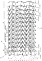
- FIG. 2 is a structure diagram showing the knitting structure of the braided fastener stringer of the present embodiment
- FIG. 3 is a structure diagram of each thread forming the braided fastener stringer.
- the weft insertion is drawn by bending so as not to overlap with the points in the organizational chart for easy viewing.
- the front-rear direction refers to the tape length direction of the fastener tape parallel to the sliding direction of the slider, and in particular, the direction in which the slider slides so as to mesh the left and right element rows (closing direction).
- the front is defined as the front
- the sliding direction is defined as the rear so as to separate the left and right element rows.
- the left-right direction refers to the tape width direction of the fastener tape, for example, a direction orthogonal to the sliding direction of the slider and parallel to the front surface (upper surface) and the back surface (lower surface) of the fastener tape.
- the vertical direction refers to a direction orthogonal to the front-rear direction and the left-right direction, for example, a tape front-back direction orthogonal to the front surface and the back surface of the fastener tape.
- the direction on the side where the slider pull is arranged with respect to the fastener tape is upward, and the direction on the opposite side is downward.
- the direction parallel to the length direction of the fastener tape is the wale direction
- the direction orthogonal to the wale direction is the course direction.
- the slide fastener 1 of the present embodiment shown in FIG. 1 has a pair of left and right braided fastener stringers 10 and sliders 40 attached to the left and right element rows 11 provided on the braided fastener stringer 10.
- the element rows 11 of the left and right braided fastener stringers 10 are meshed with each other over the entire length direction to form a fastener chain.
- the fastener tape 20 of the braided fastener stringer 10 is a tape surface (first tape surface) which is a surface on the side exposed to the outside and a tape back surface (first tape surface) arranged on the opposite side. It has 2 tape surfaces).
- the element row 11 is provided on the back side of the tape of the fastener tape 20. Therefore, the slide fastener 1 of the present embodiment is formed as a so-called back-use type slide fastener in which the element row 11 is hidden behind the fastener tape 20 and becomes invisible or difficult to see when the slide fastener 1 is closed. ..
- the slider 40 of the present embodiment is formed substantially in the same manner as the slider used in the conventional back-use type slide fastener. Therefore, in the present embodiment, detailed description of the slider 40 will be omitted.
- Each of the left and right braided fastener stringers 10 has a fastener tape 20 having a tape main body portion 21 and an element mounting portion 22, and a plurality of coil-shaped continuous fastener elements 12 woven into the element mounting portion 22.
- the element row 11 is formed along the length direction of the fastener tape 20 by the plurality of fastener elements 12 woven into the fastener tape 20.
- a film member made of synthetic resin (not shown) is adhered to the tape surface of the fastener tape 20 by adhesion. Further, the fastener tape 20 including the film member is subjected to a water repellent treatment. As a result, the slide fastener 1 is water-stopped.
- the braided fastener stringer of the present invention may be formed as a normal type braided fastener stringer that does not have water stopping property by not applying the water repellent treatment. Further, the braided fastener stringer of the present invention may be formed without attaching a film member to the fastener tape 20.
- Each braided slide fastener 1 of the present embodiment is knitted by a warp knitting machine (for example, a double Russell knitting machine) having two rows of needle beds composed of a back row B and a front row F.
- the back row B and the front row F of the needle bed are also referred to as a back needle row and a front needle row, respectively.
- the fastener element 12 of the present embodiment is formed of a single synthetic resin monofilament, and has substantially the same form as a general fastener element used in a conventional braided fastener stringer.
- each fastener element 12 of the present embodiment has a meshing head, an upper leg portion extending in the tape width direction from the upper end portion of the meshing head, and a lower leg extending in the tape width direction from the lower end portion of the meshing head. It has a portion and a connecting portion (also referred to as an inversion portion) that connects the fastener elements 12 adjacent to each other in the tape length direction.
- the fastener element 12 projects the meshing head outward from the tape side edge on the element mounting portion 22 side of the fastener tape 20, and the upper leg portion and the lower leg portion become the element mounting portion 22. It is woven and fixed.
- the tape side edge on the element mounting portion 22 side of the fastener tape 20 is the tape inner edge
- the tape side edge on the opposite side is the tape outer edge.
- the tape inner edge of the fastener tape 20 is the opposite side edge of the braided fastener stringer 10 of the meshing partner facing the fastener tape 20.
- the fastener tape 20 of the present embodiment has a warp knitting structure knitted by the warp knitting machine described above.
- the fastener tape 20 has 14 rows of wales from the first wales W1 to the 14th wales W14 from the inner edge of the tape to the outer edge of the tape.
- the wales arranged closest to the inner edge of the tape of the fastener tape 20 are the first wales W1
- the second wales W2 to the 14th wales W14 are in the course direction from the first wales W1 toward the outer edge of the tape. It is formed in order.
- the number of rows of wales formed on the fastener tape 20 is not particularly limited, and the number of rows of wales can be increased or decreased depending on the use of the braided fastener stringer 10.
- the fastener tape 20 has a tape main body portion 21 and an element mounting portion 22 extending in the tape width direction from the inner side edge portion of the tape main body portion 21 toward the meshing partner side.
- the element mounting portion 22 of the fastener tape 20 is formed by three rows of wales, the first wales W1 to the third wales W3.
- the tape body 21 is formed by 11 rows of wales from the 4th wales W4 to the 14th wales W14.
- the selvage portion of the fastener tape 20 is formed by three rows of 12th wales W12 to 14th wales W14 arranged near the outer edge of the tape of the tape main body portion 21.
- the ground structure of the fastener tape 20 (that is, the ground structure of the tape main body portion 21 and the ground structure of the element mounting portion 22) is knitted in a single structure by the back row B of the warp knitting machine.
- the fixing chain knitting yarn 34 which will be described later, is arranged on the element mounting portion 22 and is entwined with the ground structure of the element mounting portion 22 in a single structure by the front row F of the warp knitting machine.
- the ground structure of the fastener tape 20 is knitted using three types of yarns: a chain knitting yarn 31, a single satin knitting yarn 32, and a weft insertion yarn 33.
- the chain knitting yarn 31 is knitted with a knitting structure of (0-1 / 1-1 / 1-0 / 0-0) and is arranged on each of the first wales W1 to the 14th wales W14.
- the chain knitting yarn 31 of each wale has a needle loop of an opening formed in each course and a sinker loop connecting needle loops adjacent to each other in the wale direction. They are connected by sinker loops and formed in a chain along the wale direction.
- the chain knitting yarn 31a arranged on the first wale W1 on the inner edge of the tape is the most among the chain knitting yarns 31 arranged on the first wale W1 to the 14th wale W14. Thick threads are arranged.
- the chain knitting yarn 31a arranged on the first wale W1 is the other chain knitting yarn 31b arranged on the element mounting portion 22 (in the case of the present embodiment, the second and third wale W2, It has a thickness of 1.5 times or more and 4 times or less, preferably 3 times the thickness of the chain knitting yarn 31b) arranged in W3.
- the chain knitting yarn 31a arranged on the first wale W1 has a thickness of 310 decitex
- the chain knitting yarn 31b arranged on the second and third wales W2 and W3 is 110. It has the thickness of decitex.
- the element attachment portion 22 and the tape body portion 21 of the fastener tape 20 do not have to be thickened without thickening the chain knitting yarn 31b arranged on the second and third wales W2 and W3 that actually fix the fastener element 12.
- the dimension (width dimension) in the tape width direction from the boundary portion 23 to the inner edge of the tape of the element mounting portion 22 can be easily secured to be large.
- the distance between the left and right fastener tapes 20 in the closed state of the slide fastener 1 can be reduced to 0.35 mm or less, preferably 0.30 mm or less.
- the chain knitting yarns 31c arranged on the 12th wales W12 to the 14th wales W14 forming the ears of the tape main body 21 are the chain knitting yarns arranged on other than the ears of the tape main body 21. It is formed thicker than 31d (in the case of the present embodiment, the chain knitting yarn 31d arranged on the fourth wale W4 to the eleventh wale W11).
- the chain knitting yarns 31d arranged on the 4th wales W4 to the 11th wales W11 have a thickness of 110 decitex
- the chain knitting yarns arranged on the 12th wales W12 to the 14th wales W14 have a thickness of 220 decitex.
- the single satin knitting yarn 32 is knitted with a knitting structure of (1-0 / 2-2 / 3-4 / 2-2). Each single satin knitting yarn 32 is arranged over four adjacent rows of wales. Further, the single satin knitting yarn 32 has closed needle loops alternately formed on two rows of wales on the left and right ends of the four rows, and sinker loops connecting the needle loops of the wales on both ends. ..
- the needle loops of the single satin knitting yarn 32 are alternately formed in the wales direction on two rows of wales arranged at positions three rows apart from each other in the course direction. Therefore, between the two wales on which the needle loop of the single satin knitting yarn 32 is formed, two wales on which the needle loop is not formed by the single satin knitting yarn 32 are arranged.
- the sinker loop of the single satin knitting yarn 32 connects the needle loop formed on one wale and the needle loop formed on the other wale. Therefore, the sinker loops of the single satin knitting yarn 32 are arranged long over the distance between the three stitches so as to straddle the two wales between the courses. In the present embodiment, the sinker loop of the single satin knitting yarn 32 appears on the back surface of the tape of the fastener tape 20 (the tape surface on the side where the film member is not attached).
- 10 single satin knitting yarns 32 are arranged so that needle loops of the single satin knitting yarns 32 are formed on each of the first wales W1 to the thirteenth wales W13. Therefore, the needle loop forming each of the first wales W1 to the thirteenth wales W13 includes both the needle loop of the chain knitting yarn 31 and the needle loop of the single satin knitting yarn 32. .. In particular, in each of the fourth wales W4 to the thirteenth wales W13 forming the tape main body 21, the needle loop of the chain knitting yarn 31 and the needle loop of the single satin knitting yarn 32 in all the stitches formed in the back row B. Both are formed. As a result, the fastener tape 20 can stably have an appropriate tape strength.
- the 14th wale W14 formed on the outermost edge of the fastener tape 20 does not have a needle loop of the single satin knitting yarn 32, but only a needle loop of the chain knitting yarn 31.
- the outer edge of the fastener tape 20 can be formed thinly, so that when the braided fastener stringer 10 is viewed, the fastener tape 20 tends to give a thin or light impression. Further, when the fastener tape 20 is touched with a finger, the fastener tape 20 can be easily felt thin. Further, the flexibility of the fastener tape 20 can be improved by reducing the number of needle loops formed on the 14th wales W14 to be smaller than the number of other wales of the tape body 21.
- the wales of the element mounting portion 22 (first wales W1, second wales W2, or third wales W3) and the wales of the tape body portion 21 (fourth wales W4, fifth wales W4) It has a first single satin knitting yarn 32a that alternately forms needle loops on W5 or a sixth wale W6), and a second single satin knitting yarn 32b that forms needle loops only on the wales of the tape body 21.
- the sinker loop of the first single satin knitting yarn 32a is arranged across the boundary portion 23 of the tape main body portion 21 and the element mounting portion 22.
- the boundary portion 23 between the tape main body portion 21 and the element mounting portion 22 is located between the third wale W3 and the fourth wale W4. That is, in the present embodiment, the sinker loop of the three first single satin knitting yarns 32a and the two weft insertion yarns 33 form the boundary portion 23 between the tape main body portion 21 and the element mounting portion 22 between the courses. It is arranged to cross. Further, in this case, the sinker loop of the first single satin knitting yarn 32a and the two weft insertion yarns 33 intersect each course as described later. As a result, the tape strength of the boundary portion 23 between the tape main body portion 21 and the element mounting portion 22 and the tape strength of the portion in the vicinity of the boundary portion 23 are increased.
- the first single satin knitting yarn 32a that crosses the boundary portion 23 is formed thicker than the second single satin knitting yarn 32b.
- the first single satin knitting yarn 32a has a thickness of 1.1 times or more and 2.0 times or less, preferably 1.4 times or more and 1.6 times or less the thickness of the second single satin knitting yarn 32b.
- the first single satin knitting yarn 32a of the present embodiment has a thickness of 167 decitex
- the second single satin knitting yarn 32b has a thickness of 110 decitex.
- the portion where the tape strength is increased by the first single satin knitting yarn 32a is a portion where the flange portion of the slider 40 easily comes into contact with the slide fastener 1. Therefore, since the fastener tape 20 includes the first single satin knitting yarn 32a and has high tape strength as described above, the fastener tape 20 is damaged even if the sliding operation of the slider 40 is repeated. It can be difficult.
- a plurality of weft insertion threads 33 are inserted into the entire first wales W1 to 14th wales W14.
- Each weft insertion thread 33 is inserted in a zigzag shape over 3 wales.
- the weft insertion thread 33 of the present embodiment is inserted in a direction intersecting the sinker loop of the single satin knitting thread 32 between each course.
- the direction in which the weft insertion yarn 33 is folded back by the needle loop and the sinker loop of the single satin knitting yarn 32 are from the needle loop.
- the extending direction means that the direction of extension is deviated from the direction of the wales by one course.
- the weft insertion thread 33a arranged closest to the inner edge of the tape folded back by the first wale W1 is formed thinner than the other weft insertion threads 33 arranged on the fastener tape 20.
- the weft insertion yarn 33a can weaken the force (tension) that pulls the thick chain knitting yarn 31a arranged on the first wale W1 in the direction of approaching the tape main body portion 21. Therefore, it becomes easy to secure a large dimension in the tape width direction from the boundary portion 23 to the inner edge of the tape of the element mounting portion 22, and as a result, the gap formed between the left and right fastener tapes 20 can be reduced.
- the fixing chain knitting yarn 34 has a knitting structure of (0-0 / 0-1 / 1-1 / 1-0) by the front row F of the warp knitting machine, and the second wales of the element mounting portion 22. It is woven into W2 and the third wales W3. That is, the ground structure of the fastener tape 20 and the knitting portion of the chain knitting yarn 34 for fixing are knitted in separate single structures by the back row B and the front row F of the warp knitting machine. As a result, the flexibility of the fastener tape 20 can be increased, the weight of the braided fastener stringer 10 can be reduced, and the productivity can be improved.
- the upper leg portion and the lower leg portion of the fastener element 12 are inserted so as to be sandwiched between the ground structure of the element mounting portion 22 and the chain knitting yarn 34 for fixing.
- the sinker loop of the fixing chain knitting yarn 34 intersects and is entangled with the ground structure of the element mounting portion 22. More specifically, the sinker loop of the fixing chain knitting yarn 34 is entwined with at least one sinker loop of the chain knitting yarn 31 and the single satin knitting yarn 32 forming the ground structure.
- the fixing chain knitting yarn 34 is integrated with the ground structure of the element mounting portion 22.
- the fastener element 12 is woven into the element mounting portion 22 together with the fixing chain knitting yarn 34 and is firmly fixed. In this case, the fastener element 12 is fixed by the upper leg portion and the lower leg portion of the fastener element 12 being sandwiched between the fixing chain knitting yarn 34 and the ground structure of the element mounting portion 22.
- the fixing chain knitting yarn 34 is the first fixing chain knitting yarn 34a arranged on the second wale W2 near the inner edge of the tape and the tape main body portion 21 arranged on the third wale W3. It has a second fixing chain knitting yarn 34b.
- a yarn thicker than any of the yarns forming the ground structure of the fastener tape 20 is used.
- the first fixing chain knitting yarn 34a and the second fixing chain knitting yarn 34b are formed by aligning two yarns having a thickness of 220 decitex. As a result, the fastener element 12 can be firmly fixed to the element mounting portion 22 of the fastener tape 20 so that the position of the fastener element 12 does not shift.
- the second fixing chain knitting yarn 34b of the present embodiment includes two yarns having a thickness of 220 decitex when knitting the warp knitting for knitting the braided fastener stringer 10 as described later. It is formed to include auxiliary fibers to be removed. This auxiliary fiber is pulled out from the fastener tape 20 and disappears after the knitting process is completed. Therefore, in the manufactured braided fastener stringer 10, the second fixing chain knitting yarn 34b is formed by two yarns having a thickness of 220 decitex. Regarding the first fixing chain knitting yarn 34a of the present embodiment, the knitting process of the braided fastener stringer 10 is performed without including auxiliary fibers.
- the force for pressing the fastener element 12 with the second fixing chain knitting yarn 34b is applied.
- the force of pressing the fastener element 12 with the first fixing chain knitting yarn 34a can be weakened.
- the fastener tape 20 is compared with the case where the knitting process is performed without including the fibers to be removed in, for example, the first fixing chain knitting yarn 34a and the second fixing chain knitting yarn 34b. It becomes easy to allow the movement of each fastener element 12 woven into.
- the flexibility of the braided fastener stringer 10 can be increased more effectively, and the slidability of the slider 40 in the slide fastener 1 can be further improved.
- the fastener element 12 can be stably fixed to the element mounting portion 22.
- the meshing strength (horizontal pulling strength) of the fastener chain and the meshing strength (bending strength) when the fastener chain is bent in the front and back directions of the tape can be appropriately secured.
- a warp knitting process for knitting the braided fastener stringer 10 is performed using a warp knitting machine provided with two rows of needle beds composed of a back row B and a front row F.
- the needle loop of the fixing chain knitting yarn 34 is formed by the front row F, and the fixing chain knitting yarn is formed.
- the 34 sinker loops are entwined with the ground structure of the fastener tape 20.
- the fastener element 12 formed from the monofilament is inserted between the ground structure of the fastener tape 20 and the fixing chain knitting yarn 34.
- the ground structure of the fastener tape 20 is knitted using the chain knitting yarn 31, the single satin knitting yarn 32, and the weft insertion yarn 33 described above.
- the fixing chain knitting yarn 34 the first fixing chain knitting yarn 34a formed by aligning two yarns having a thickness of 220 decitex, and 2 having the aligned thickness of 220 decitex 2
- the fastener element 12 is knitted into the fastener tape 20 using a second fixing chain knitting yarn 34b containing a book yarn and auxiliary fibers.
- a braided fastener stringer 10 in which a plurality of fastener elements 12 are woven at regular intervals is knitted on the element mounting portion 22 of the fastener tape 20.
- the braided fastener stringer 10 obtained at this time has a warp knitting structure as shown in FIGS. 2 and 3.
- one braided fastener stringer 10 may be continuously manufactured, or two braided fastener stringers 10 are knitted in a state where the left and right element rows 11 are meshed with each other.
- Fastener chains may be manufactured continuously.
- the obtained braided fastener stringers 10 are combined in pairs to form a fastener chain, and the auxiliary fibers contained in the second fixing chain knitting yarn 34b are pulled out. Then, an adhesive is applied to the tape surfaces of the left and right fastener tapes 20 in the fastener chain. Subsequently, one film member made of synthetic resin is superposed and attached to the surface of the tape coated with the adhesive. As a result, the film member is adhered to the fastener tape 20.
- the type and material of the adhesive for adhering the film member are not particularly limited.
- the method and means for attaching the film member to the fastener tape 20 are not particularly limited, and the film member may be attached to the fastener tape 20 by a method or means other than adhesion.
- the fastener chain to which the film member is attached is subjected to a water repellent treatment. Then, by cutting the film member along the length direction of the fastener chain at the boundary between the left and right fastener tapes 20, a fastener chain having water stopping property is manufactured. Further, by attaching the slider 40 to the left and right element rows 11 of the manufactured fastener chain, the slide fastener 1 having the water-stopping property shown in FIG. 1 is manufactured.
- the ground structure of the left and right fastener tapes 20 is knitted using a single satin knitting yarn 32 that forms a sinker loop long between each course. .. Therefore, the left and right braided fastener stringers 10 have high flexibility.
- the sinker loop of the single satin knitting yarn 32 is fastened on the back surface of the tape on the side where the fastener element 12 of the fastener tape 20 is knitted (in other words, the tape surface on the side where the film member is not attached). It appears longer in the direction inclined with respect to the tape width direction of the tape 20. As a result, the back surface of the fastener tape 20 is formed on a smooth surface that gives a good touch. Further, the fastener tape 20 can have a good texture due to the single satin knitting yarn 32.
- the tape strength of the boundary portion 23 between the tape main body portion 21 and the element mounting portion 22 of the fastener tape 20 and the vicinity thereof is three thick first singles. It is enhanced by a satin knitting yarn 32a and two weft insertion yarns 33. As a result, damage caused by rubbing of the fastener tape 20 with the slider 40 or the like can be suppressed.
- the slide fastener 1 of the present embodiment which is soft, soft to the touch, and has appropriate tape strength, is suitably used for clothing that comes into direct contact with the skin, clothing that is made of a thin cloth, and the like. ..
- the gap between the left and right fastener tapes 20 formed when the slide fastener 1 is closed is 0. It can be reduced to 35 mm or less, preferably 0.30 mm or less. As a result, the meshed left and right element rows 11 can be made difficult to see from the tape surface side of the fastener tape 20 through the gap between the left and right fastener tapes 20.
- the length of the film member that adheres to the fastener tape 20 extends from the inner edge of the fastener tape 20 toward the meshing head side in the tape width direction. Can be shortened. This makes it difficult to cause appearance defects such as white lines observed between the left and right fastener tapes in a conventional water-stopping slide fastener. As a result, the appearance quality of the water-stopping slide fastener 1 can be improved. Further, by reducing the gap between the left and right fastener tapes 20, the slide fastener 1 can stably provide good water stopping property.
- the braided fastener stringer 10 of the above-described embodiment is used for the back-use type slide fastener 1, but the braided fastener stringer of the present invention is a normal type slide fastener in which the element row is exposed to the outside. Can be applied in the same way.
- auxiliary fibers are previously included only in the second fixing chain knitting yarn 34b of the fixing chain knitting yarn 34, and the auxiliary fibers are contained therein. Auxiliary fibers are removed after knitting.
- the auxiliary fiber may be contained only in the first fixing chain knitting yarn 34a of the fixing chain knitting yarn 34, or the first fixing may be included. Both the chain knitting yarn 34a and the second fixing chain knitting yarn 34b may contain auxiliary fibers.
- the braided fastener stringer 10 may be knitted without including auxiliary fibers. In this case, for example, a water-soluble fiber is used as the auxiliary fiber, and pulling out the fiber after the knitting process includes dissolving the water-soluble fiber in a liquid.
Abstract
This interwoven fastener stringer (10) is characterized in that the chain stitch yarn (31) that is disposed in the innermost edge wale (W1), which is furthest from the main body section (21) of the tape, in the element attachment section (22) is the thickest yarn of all the chain stitch yarns (31) used in the fastener tape (20). As a result, it is possible to reduce the spacing of the gap that is formed between left and right fastener tapes when forming a slide fastener by combining two interwoven fastener stringers.
Description
本発明は、ファスナーエレメントがファスナーテープに編み込まれる編込みファスナーストリンガー、その編込みファスナーストリンガーを有するファスナーチェーン、及び、その編込みファスナーストリンガーを製造する方法に関する。
The present invention relates to a braided fastener stringer in which a fastener element is woven into a fastener tape, a fastener chain having the braided fastener stringer, and a method for manufacturing the braided fastener stringer.
スライドファスナー用ファスナーストリンガーの一つとして、編込みファスナーストリンガーが知られている。編込みファスナーストリンガーでは、合成樹脂製のモノフィラメントから形成される連続した複数のファスナーエレメントが、ファスナーテープのテープ側縁部に編み込まれている。
As one of the fastener stringers for slide fasteners, the braided fastener stringer is known. In the braided fastener stringer, a plurality of continuous fastener elements formed from a monofilament made of synthetic resin are woven into the tape side edge portion of the fastener tape.
この場合、ファスナーテープのファスナーエレメントが編み込まれる部分は、エレメント取付部と呼ばれている。編込みファスナーストリンガーは、例えば2列の針床をもったダブル経編機を用いて、ファスナーテープを編成しながら、連続したファスナーエレメントをファスナーテープのエレメント取付部に編み込むことによって製造される。
In this case, the part where the fastener element of the fastener tape is woven is called the element mounting part. The braided fastener stringer is manufactured by knitting a continuous fastener element into an element attachment portion of the fastener tape while knitting the fastener tape using, for example, a double warp knitting machine having two rows of needle beds.
編込みファスナーストリンガーの一例が、例えば国際公開第2011/077568号(特許文献1)及び国際公開第2013/011559号(特許文献2)等に記載されている。
特許文献1の編込みファスナーストリンガーでは、ファスナーテープにおけるエレメント取付部の地組織が、鎖編糸と、トリコット編糸と、二目編糸とによって、シングル組織で編成されている。このエレメント取付部の地組織と、シングル組織で編み込まれる固定用鎖編糸とによって、各ファスナーエレメントが挟持されて固定されている。 Examples of braided fastener stringers are described in, for example, International Publication No. 2011/077568 (Patent Document 1) and International Publication No. 2013/011559 (Patent Document 2).
In the braided fastener stringer ofPatent Document 1, the ground structure of the element attachment portion of the fastener tape is knitted in a single structure by a chain knitting yarn, a tricot knitting yarn, and a second knitting yarn. Each fastener element is sandwiched and fixed by the ground structure of the element mounting portion and the fixing chain knitting yarn knitted with a single structure.
特許文献1の編込みファスナーストリンガーでは、ファスナーテープにおけるエレメント取付部の地組織が、鎖編糸と、トリコット編糸と、二目編糸とによって、シングル組織で編成されている。このエレメント取付部の地組織と、シングル組織で編み込まれる固定用鎖編糸とによって、各ファスナーエレメントが挟持されて固定されている。 Examples of braided fastener stringers are described in, for example, International Publication No. 2011/077568 (Patent Document 1) and International Publication No. 2013/011559 (Patent Document 2).
In the braided fastener stringer of
特許文献2の編込みファスナーストリンガーでは、エレメント取付部の地組織が、鎖編糸と、二目編糸又はトリコット編糸と、2つのウェールにジグザグ状に挿入される緯疎入糸とによって、シングル組織で編成されている。また、ファスナーエレメントを固定する固定用鎖編糸は、地組織のニードルループに絡む第1ニードルループと、ファスナーエレメントを押さえ付ける第2ニードルループとを形成するダブル組織で編み込まれている。
In the braided fastener stringer of Patent Document 2, the ground structure of the element mounting portion is formed by a chain knitting yarn, a second knitting yarn or a tricot knitting yarn, and a weft knitting yarn inserted in a zigzag shape on two wales. It is organized in a single organization. Further, the fixing chain knitting yarn for fixing the fastener element is woven with a double structure forming a first needle loop entwined with the needle loop of the ground structure and a second needle loop for pressing the fastener element.
編込みファスナーストリンガーは、経編組織を有するファスナーテープにファスナーエレメントが直接編み込まれて形成されている。このため、編込みファスナーストリンガーを用いて製造されるスライドファスナーは、厚さが薄く、柔軟性に優れているため、肌着や生地が薄い上着のような衣料品等に好適に使用される。
The braided fastener stringer is formed by directly knitting a fastener element into a fastener tape having a warp knitting structure. Therefore, the slide fastener manufactured by using the braided fastener stringer is thin and has excellent flexibility, and is therefore preferably used for clothing such as underwear and outerwear with a thin fabric.
近年、衣料品などの衣類を含む様々な製品では、それぞれの用途に応じて性質を改善すること、又は、様々な機能の付与によって付加価値を高めること等が行われている。例えば日常的に使用される衣料品等の場合、軽量化、柔軟性の向上、肌触りの良さ、及び着心地の良さ等が求められることが多い。
In recent years, various products including clothing such as clothing have been improved in properties according to their respective uses, or added value by adding various functions. For example, in the case of clothing that is used on a daily basis, weight reduction, improvement in flexibility, good touch, and comfort are often required.
このため、衣料品に取り付けられるスライドファスナーに対しても、様々な要望が寄せられている。例えば編込みファスナーストリンガーを有するスライドファスナーについては、スライドファスナーをより薄くすること、柔軟性を更に高めること、肌触りを更に良くすること、又はファスナーテープのテープ強度を高めること等が望まれている。
For this reason, various requests have been received for slide fasteners that can be attached to clothing. For example, for a slide fastener having a braided fastener stringer, it is desired to make the slide fastener thinner, further increase the flexibility, further improve the touch, or increase the tape strength of the fastener tape.
ところで、スライドファスナーの形態の一つとして、ファスナーエレメントが、スライドファスナーの閉鎖時に見えなくなるように、ファスナーテープのテープ裏面側に取り付けられる所謂裏使いタイプのスライドファスナーが知られている。このような裏使いタイプのスライドファスナーが編込みファスナーストリンガーを用いて製造される場合には、例えば織組織のファスナーテープにファスナーエレメントが縫着された一般的な裏使いタイプのスライドファスナーに比べて、スライドファスナーの閉鎖時に左右のファスナーテープ間に隙間が形成され易くなる。その結果、編込みファスナーストリンガーを有する裏使いタイプのスライドファスナーの場合、ファスナーテープの裏側に隠すように配されるファスナーエレメントの一部が、左右のファスナーテープ間の隙間から容易に見える可能性がある。
By the way, as one of the forms of the slide fastener, a so-called back-use type slide fastener is known in which the fastener element is attached to the back side of the tape of the fastener tape so that it cannot be seen when the slide fastener is closed. When such a back-use type slide fastener is manufactured by using a braided fastener stringer, it is compared with a general back-use type slide fastener in which a fastener element is sewn on a fastener tape having a woven structure, for example. , When the slide fastener is closed, a gap is likely to be formed between the left and right fastener tapes. As a result, in the case of a back-use type slide fastener with a braided fastener stringer, a part of the fastener element arranged so as to be hidden behind the fastener tape may be easily visible from the gap between the left and right fastener tapes. is there.
更に、裏使いタイプのスライドファスナーの場合、ファスナーテープに合成樹脂製のフィルム部材を貼り付けるとともに、ファスナーテープに撥水処理を施すことによって、スライドファスナーの閉鎖時に、水などの液体をファスナーテープの一方のテープ面側から他方のテープ面側に浸入させ難くする止水性をスライドファスナーに持たせることが可能となる。このような止水性を備えるスライドファスナーは、一般的に、止水性スライドファスナーと呼ばれる。
Furthermore, in the case of a back-use type slide fastener, a synthetic resin film member is attached to the fastener tape, and the fastener tape is treated to be water repellent so that liquid such as water can be applied to the fastener tape when the slide fastener is closed. It is possible to give the slide fastener a water-stopping property that makes it difficult for the slide fastener to penetrate from one tape surface side to the other tape surface side. A slide fastener having such a water-stopping property is generally called a water-stopping slide fastener.
しかし、編込みファスナーストリンガーを有する裏使いタイプのスライドファスナーの場合、左右のファスナーテープ間に上述したような隙間が形成されることによって、ファスナーテープに合成樹脂製のフィルム部材を貼り付けたときに、ファスナーテープ間の隙間の上にフィルム部材がファスナーテープから飛び出して配されることがある。その結果、フィルム部材のファスナーテープから飛び出した部分が、テープ長さ方向に沿った直線状の白い線のように見えるため、スライドファスナーの外観品質の低下を招く虞がある。また、左右のファスナーテープ間に上述したような隙間が形成されると、スライドファスナーの止水性を低下させることも考えられる。従って、裏使いタイプの止水性スライドファスナーには、編込みファスナーストリンガーが用いられることは殆どなかった。
However, in the case of a back-use type slide fastener having a braided fastener stringer, when the synthetic resin film member is attached to the fastener tape by forming the gap as described above between the left and right fastener tapes. , The film member may be arranged so as to protrude from the fastener tape over the gap between the fastener tapes. As a result, the portion of the film member protruding from the fastener tape looks like a straight white line along the tape length direction, which may lead to deterioration of the appearance quality of the slide fastener. Further, if the above-mentioned gap is formed between the left and right fastener tapes, it is possible to reduce the water stopping property of the slide fastener. Therefore, the braided fastener stringer was rarely used for the back-use type water-stopping slide fastener.
本発明は上記従来の課題に鑑みてなされたものであって、その目的は、スライドファスナーの閉鎖時に左右のファスナーテープ間に形成される隙間を小さくすることが可能な編込みファスナーストリンガーと、その編込みファスナーストリンガーを有するファスナーチェーンと、その編込みファスナーストリンガーを製造する方法とを提供することにある。
The present invention has been made in view of the above-mentioned conventional problems, and an object thereof is a braided fastener stringer capable of reducing the gap formed between the left and right fastener tapes when the slide fastener is closed, and a braided fastener stringer thereof. It is an object of the present invention to provide a fastener chain having a braided fastener stringer and a method for manufacturing the braided fastener stringer.
上記目的を達成するために、本発明により提供される編込みファスナーストリンガーは、経編組織を有するファスナーテープと、合成樹脂製のモノフィラメントから形成される複数のファスナーエレメントとを有し、前記ファスナーテープは、テープ本体部と、前記テープ本体部の一方の側縁部からテープ幅方向に延びるとともに前記ファスナーエレメントの一部が編み込まれるエレメント取付部とを有し、前記ファスナーテープは、ウェール方向に沿って複数のニードルループを鎖状に形成する複数の鎖編糸を含む編込みファスナーストリンガーであって、前記エレメント取付部の前記テープ本体部から最も離れた最内縁のウェールに配される前記鎖編糸は、前記ファスナーテープに用いられる全ての前記鎖編糸の中で最も太い糸であることを特徴とするものである。
In order to achieve the above object, the braided fastener stringer provided by the present invention has a fastener tape having a warp knitted structure and a plurality of fastener elements formed from a monofilament made of synthetic resin, and the fastener tape. Has an element main body portion and an element mounting portion extending in the tape width direction from one side edge portion of the tape main body portion and a part of the fastener element is woven, and the fastener tape is along the wale direction. A braided fastener stringer including a plurality of chain knitting yarns that form a plurality of needle loops in a chain shape, and the chain knitting is arranged on the innermost wales of the element mounting portion farthest from the tape main body portion. The yarn is characterized in that it is the thickest yarn among all the chain knitting yarns used for the fastener tape.
本発明に係る編込みファスナーストリンガーにおいて、前記ファスナーテープは、前記鎖編糸と、互いに3列離れた位置に配される2つのウェールにニードルループを交互に形成するシングルサテン編糸と、複数のウェールに亘ってジグザグ状に挿入される緯挿入糸とによりシングル組織で編成される地組織を有し、前記ファスナーエレメントは、前記ファスナーテープの前記地組織と、シングル組織で編み込まれる固定用鎖編糸との間に挿入されて編み込まれていることが好ましい。
In the braided fastener stringer according to the present invention, the fastener tape includes the chain knitting yarn, a single satin knitting yarn in which needle loops are alternately formed on two wales arranged at positions three rows apart from each other, and a plurality of single satin knitting yarns. It has a ground structure knitted with a single structure by weft insertion threads inserted in a zigzag shape over a wales, and the fastener element is a fixing chain knitted with the ground structure of the fastener tape and the single structure. It is preferable that it is inserted between the yarn and knitted.
この場合、前記テープ本体部と前記エレメント取付部の境界部となるウェール間において、少なくとも3本の前記シングルサテン編糸と、少なくとも2本の前記緯挿入糸とが互いに交差する方向に配されていることが好ましい。
In this case, at least three single satin knitting yarns and at least two weft insertion yarns are arranged in a direction intersecting each other between the wales serving as the boundary between the tape main body portion and the element mounting portion. It is preferable to have.
また、前記シングルサテン編糸は、前記エレメント取付部のウェールと前記テープ本体部のウェールとにニードルループを交互に形成する第1シングルサテン編糸と、前記テープ本体部における2つのウェールにニードルループを交互に形成する第2シングルサテン編糸とを有し、前記第1シングルサテン編糸は、前記第2シングルサテン編糸よりも太い糸であることが好ましい。
Further, the single satin knitting yarn includes a first single satin knitting yarn in which needle loops are alternately formed on the wales of the element mounting portion and the wales of the tape main body portion, and needle loops on two wales of the tape main body portion. The first single satin knitting yarn is preferably thicker than the second single satin knitting yarn.
更に、前記テープ本体部の前記エレメント取付部から最も離れた位置に配される最外縁のウェールを形成するニードルループは、前記鎖編糸のニードルループのみを有し、前記テープ本体部における前記最外縁のウェール以外のウェールを形成するニードルループは、前記鎖編糸のニードルループと、前記シングルサテン編糸のニードルループとを有することが好ましい。
Further, the needle loop forming the outermost wales arranged at the position farthest from the element mounting portion of the tape main body portion has only the needle loop of the chain knitting yarn, and the outermost needle loop in the tape main body portion. The needle loop forming the wales other than the outer edge wales preferably includes the needle loop of the chain knitting yarn and the needle loop of the single satin knitting yarn.
次に、本発明により提供されるファスナーチェーンは、上述した形態を備えた2つの前記編込みファスナーストリンガーを有することを特徴とするものである。
本発明のファスナーチェーンにおいて、2つの前記ファスナーテープ間の間隔は、0.35mm以下であることが好ましい。 Next, the fastener chain provided by the present invention is characterized by having the two braided fastener stringers having the above-described form.
In the fastener chain of the present invention, the distance between the two fastener tapes is preferably 0.35 mm or less.
また、前記ファスナーテープは、前記ファスナーエレメントが編み込まれる側の第1テープ面と、前記第1テープ面の反対側の第2テープ面とを有し、前記ファスナーテープの前記第2テープ面に、合成樹脂製のフィルム部材が付着されていることが好ましい。
Further, the fastener tape has a first tape surface on the side where the fastener element is woven and a second tape surface on the opposite side of the first tape surface, and the second tape surface of the fastener tape has a surface. It is preferable that a film member made of synthetic resin is attached.
次に、本発明により提供される編込みファスナーストリンガーの製造方法は、経編組織を有するファスナーテープと、合成樹脂製のモノフィラメントから形成される複数のファスナーエレメントとを有し、前記ファスナーテープは、テープ本体部と、前記テープ本体部の一方の側縁部からテープ幅方向に延びるとともに前記ファスナーエレメントの一部が編み込まれるエレメント取付部とを有し、前記ファスナーテープは、ウェール方向に沿って複数のニードルループを鎖状に形成する複数の鎖編糸を含む編込みファスナーストリンガーの製造方法であって、前記エレメント取付部の前記テープ本体部から最も離れた最内縁のウェールに配される前記鎖編糸に、前記ファスナーテープに用いられる全ての前記鎖編糸の中で最も太い糸を用いることを含むことを特徴とするものである。
Next, the method for manufacturing a braided fastener stringer provided by the present invention includes a fastener tape having a warp-knitted structure and a plurality of fastener elements formed from a monofilament made of synthetic resin. It has a tape main body portion and an element mounting portion extending in the tape width direction from one side edge portion of the tape main body portion and a part of the fastener element is woven into the tape main body portion. A method for manufacturing a braided fastener stringer including a plurality of chain knitting yarns that form a chain of needle loops, wherein the chain is arranged on the innermost wales of the element mounting portion farthest from the tape body portion. The knitting yarn is characterized by using the thickest yarn among all the chain knitting yarns used for the fastener tape.
本発明に係る編込みファスナーストリンガーの製造方法は、前記ファスナーテープの地組織を、前記鎖編糸と、互いに3列離れた位置に配される2つのウェールにニードルループを交互に形成するシングルサテン編糸と、複数のウェールに亘ってジグザグ状に挿入される緯挿入糸とを用いてシングル組織で編成しながら、前記ファスナーエレメントを、前記ファスナーテープの前記地組織と、シングル組織で編み込まれる固定用鎖編糸との間に挿入して編み込むことを含むことが好ましい。
In the method for manufacturing a braided fastener stringer according to the present invention, the ground structure of the fastener tape is a single satin that alternately forms needle loops on the chain knitting yarn and two wales arranged at positions three rows apart from each other. Fixing the fastener element knitted with the ground structure of the fastener tape and the single structure while knitting with a single structure using a knitting yarn and a weft insertion yarn inserted in a zigzag shape over a plurality of wales. It is preferable to include inserting and knitting with the chain knitting yarn.
本発明に係る編込みファスナーストリンガーでは、一方向に長尺に形成される帯状のファスナーテープが複数の鎖編糸を含んでいる。また、エレメント取付部のテープ本体部から最も離れた最内縁のウェールに配される鎖編糸に、ファスナーテープに用いられる全ての鎖編糸の中で最も太い糸が用いられている。これにより、例えば最内縁のウェールに配される鎖編糸をその他の鎖編糸と同じ太さにする場合に比べて、テープ幅方向における最内縁のウェールの位置をファスナーテープのテープ本体部から遠ざけることができる。それによって、2つの編込みファスナーストリンガーを組み合わせてファスナーチェーン又はスライドファスナーを形成したときに、左右のファスナーテープ間に形成される隙間の間隔を小さくすること、具体的には、当該隙間の間隔を0.35mm以下に小さくすることができる。
In the braided fastener stringer according to the present invention, a strip-shaped fastener tape formed long in one direction contains a plurality of chain knitting yarns. Further, as the chain knitting yarn arranged on the innermost wales farthest from the tape main body portion of the element mounting portion, the thickest yarn among all the chain knitting yarns used for the fastener tape is used. As a result, the position of the innermost wales in the tape width direction is set from the tape body of the fastener tape, as compared with the case where the chain knitting yarn arranged on the innermost wales has the same thickness as other chain knitting yarns. You can keep it away. Thereby, when a fastener chain or a slide fastener is formed by combining two braided fastener stringers, the gap formed between the left and right fastener tapes is reduced, specifically, the gap between the gaps is reduced. It can be reduced to 0.35 mm or less.
本発明に係る編込みファスナーストリンガーにおいて、ファスナーテープは、鎖編糸と、シングルサテン編糸と、緯挿入糸とを用いてシングル組織で編成される地組織を有する。ここで、シングルサテン編糸は、互いに3つのウェール分だけ離れた位置に配される2つのウェールに(言い換えると、その間に2つのウェールが設けられる2つのウェール)、ニードルループを交互に形成する編糸を言う。このシングルサテン編糸は、簡単にサテン編糸と呼ばれることもある。本発明では、このようなファスナーテープの編成時に、ファスナーテープのシングル組織の地組織と、地組織とは別の針床で編み込まれるシングル組織の固定用鎖編との間に、ファスナーエレメントが1つずつ順番に挿入されて編み込まれている。
In the braided fastener stringer according to the present invention, the fastener tape has a ground structure knitted in a single structure using a chain knitting yarn, a single satin knitting yarn, and a weft insertion yarn. Here, the single satin knitting yarn alternately forms needle loops on two wales arranged at positions separated from each other by three wales (in other words, two wales with two wales in between). Say knitting yarn. This single satin knitting yarn is sometimes simply called a satin knitting yarn. In the present invention, when knitting such a fastener tape, one fastener element is provided between the ground structure of the single structure of the fastener tape and the fixing chain knitting of the single structure woven by a needle bed different from the ground structure. They are inserted and woven one by one in order.
本発明のファスナーテープの地組織には、トリコット編糸及び二目編糸が編み込まれてなく、上述したシングルサテン編糸が編み込まれている。これによって、各シングルサテン編糸の2つのウェールに形成されるニードルループが相互に適切に離れ、それによって、これらの離れたウェールのニードルループ間に配されるシングルサテン編糸のシンカーループを長くすることができる。その結果、本発明の編込みファスナーストリンガーは、例えば特許文献1及び特許文献2等のトリコット編糸及び二目編糸を有する編込みファスナーストリンガーに比べて、柔軟性を高めることができる。更に、本発明の編込みファスナーストリンガーは、例えば編成されたファスナーテープ(ニットテープ)にファスナーエレメントを縫製加工で別途に取り付けるファスナーストリンガー(すなわち、非編込みのファスナーストリンガー)と比較しても、高い柔軟性を有する。
The ground structure of the fastener tape of the present invention is not knitted with the tricot knitting yarn and the second knitting yarn, but is woven with the above-mentioned single satin knitting yarn. This allows the needle loops formed on the two wales of each single satin knit to be properly separated from each other, thereby lengthening the sinker loops of the single satin knit that are placed between the needle loops of these separated wales. can do. As a result, the braided fastener stringer of the present invention can be made more flexible than the braided fastener stringer having the tricot knitting yarn and the second knitting yarn of Patent Document 1 and Patent Document 2, for example. Further, the braided fastener stringer of the present invention is higher than, for example, a fastener stringer (that is, a non-braided fastener stringer) in which a fastener element is separately attached to a knitted fastener tape (knit tape) by sewing. Has flexibility.
また本発明では、編込みファスナーストリンガーの肌触りに関して、以下のような効果が得られることが新たに明らかになった。すなわち、本発明の編込みファスナーストリンガーでは、シングルサテン編糸のシンカーループが、各コース間において、コース方向に対して傾斜した方向に長く配されている。このようなコース方向に対して斜めに長いシンカーループをファスナーテープが有することによって、ファスナーテープのシンカーループが表出する側のテープ面を、例えば繻子織の織物のような滑らかな面に形成できる。このため、本発明における編込みファスナーストリンガーのファスナーテープは、例えば特許文献1及び特許文献2等の編込みファスナーストリンガーに比べて、良好な肌触りを有することができる。
Further, in the present invention, it has been newly clarified that the following effects can be obtained with respect to the feel of the braided fastener stringer. That is, in the braided fastener stringer of the present invention, the sinker loops of the single satin knitting yarn are arranged long in the direction inclined with respect to the course direction between the courses. By having the fastener tape have a sinker loop that is diagonally long with respect to the course direction, the tape surface on the side where the sinker loop of the fastener tape is exposed can be formed on a smooth surface such as a satin weave fabric. .. Therefore, the fastener tape of the braided fastener stringer in the present invention can have a better feel than the braided fastener stringers of Patent Document 1 and Patent Document 2, for example.
このような本発明の編込みファスナーストリンガーにおいて、テープ本体部とエレメント取付部の境界部となるウェール間において、少なくとも3本のシングルサテン編糸と、少なくとも2本の緯挿入糸とが互いに交差する方向に配されている。これにより、ファスナーテープのテープ強度を、特にファスナーテープにおけるテープ本体部とエレメント取付部との間のテープ強度を効果的に高めることができる。
In such a braided fastener stringer of the present invention, at least three single satin knitting yarns and at least two weft insertion yarns intersect each other between the wales serving as the boundary between the tape body portion and the element mounting portion. Arranged in the direction. Thereby, the tape strength of the fastener tape, particularly the tape strength between the tape main body portion and the element mounting portion of the fastener tape can be effectively increased.
本発明のシングルサテン編糸は、エレメント取付部のウェールとテープ本体部のウェールとにニードルループを交互に形成する第1シングルサテン編糸と、テープ本体部における2つのウェールにニードルループを交互に形成する第2シングルサテン編糸とを有する。また、第1シングルサテン編糸は、第2シングルサテン編糸よりも太い糸である。これにより、ファスナーテープにおけるエレメント取付部のテープ強度と、テープ本体部とエレメント取付部との間のテープ強度をより効果的に高めることができる。
In the single satin knitting yarn of the present invention, the first single satin knitting yarn in which needle loops are alternately formed on the wales of the element mounting portion and the wales of the tape body portion, and the needle loops are alternately formed on the two wales of the tape body portion. It has a second single satin knitting yarn to be formed. The first single satin knitting yarn is thicker than the second single satin knitting yarn. Thereby, the tape strength of the element mounting portion of the fastener tape and the tape strength between the tape main body portion and the element mounting portion can be more effectively increased.
本発明の編込みファスナーストリンガーにおいて、テープ本体部のエレメント取付部から最も離れた位置に配される最外縁のウェールを形成するニードルループは、鎖編糸のニードルループのみを有する。また、テープ本体部における最外縁のウェール以外のウェールを形成するニードルループは、鎖編糸のニードルループと、シングルサテン編糸のニードルループとを有する。これにより、ファスナーテープの適切なテープ強度を確保するとともに、ファスナーテープの最外縁のウェールに形成されるニードルループの数を最も少なくして、ファスナーテープのエレメント取付部とは反対側の一方のテープ側端縁を薄くすることができる。このようにファスナーテープの一方のテープ側端縁を薄くすることによって、ファスナーテープを指で触ったときに、ファスナーテープを薄く感じさせ易くすることができる。
In the braided fastener stringer of the present invention, the needle loop forming the outermost wales arranged at the position farthest from the element mounting portion of the tape main body has only the needle loop of the chain knitting yarn. Further, the needle loop forming a wales other than the outermost wales in the tape main body portion includes a needle loop of a chain knitting yarn and a needle loop of a single satin knitting yarn. This ensures proper tape strength of the fastener tape and minimizes the number of needle loops formed on the outermost wales of the fastener tape, resulting in one tape opposite the element mounting portion of the fastener tape. The side edge can be thinned. By thinning one end edge of the fastener tape in this way, it is possible to make the fastener tape feel thin when the fastener tape is touched with a finger.
次に、本発明により提供されるファスナーチェーンは、上述した形態を備えた2つの編込みファスナーストリンガーを有するものである。このような本発明のファスナーチェーンは、高い柔軟性と良好な肌触りとを有することができる。
Next, the fastener chain provided by the present invention has two braided fastener stringers having the above-described form. Such a fastener chain of the present invention can have high flexibility and good touch.
また、本発明のファスナーチェーンでは、2つのファスナーテープ間の隙間の間隔が、0.35mm以下と小さいものになる。これにより、本発明のファスナーチェーンを用いて形成される裏使いタイプのスライドファスナーは、例えば従来のファスナーチェーンを用いて形成される裏使いタイプのスライドファスナーに比べて、2つのファスナーテープ間の隙間から、ファスナーテープの裏側に配されるファスナーエレメントを見え難くすることができる。
Further, in the fastener chain of the present invention, the distance between the two fastener tapes is as small as 0.35 mm or less. As a result, the back-use type slide fastener formed by using the fastener chain of the present invention has a gap between the two fastener tapes as compared with, for example, the back-use type slide fastener formed by using the conventional fastener chain. Therefore, it is possible to make the fastener element arranged on the back side of the fastener tape difficult to see.
また、上述の裏使いタイプのスライドファスナーに合成樹脂製のフィルム部材を貼り付けるとともに撥水処理を施すことによって、止水性スライドファスナーを製造したときに、従来の止水性スライドファスナーにおいて左右のファスナーテープ間に観察されるような白い線(すなわち、フィルム部材のファスナーテープから飛び出した部分)を生じさせ難くすることができる。
Further, when a water-stopping slide fastener is manufactured by attaching a synthetic resin film member to the above-mentioned back-use type slide fastener and applying a water-repellent treatment, the left and right fastener tapes in the conventional water-stopping slide fastener are used. It is possible to make it difficult to generate a white line (that is, a portion protruding from the fastener tape of the film member) as observed between them.
更に本発明のファスナーチェーンにおいて、ファスナーテープは、ファスナーエレメントが編み込まれる側の第1テープ面と、第1テープ面の反対側の第2テープ面とを有しており、ファスナーテープの第2テープ面に、合成樹脂製のフィルム部材が付着されている。これにより、例えばファスナーチェーンに撥水処理を施すこと等によって、止水性スライドファスナーを製造できる。
Further, in the fastener chain of the present invention, the fastener tape has a first tape surface on the side where the fastener element is woven and a second tape surface on the opposite side of the first tape surface, and the second tape of the fastener tape. A film member made of synthetic resin is attached to the surface. Thereby, for example, a water-stopping slide fastener can be manufactured by applying a water-repellent treatment to the fastener chain.
次に、本発明により提供される編込みファスナーストリンガーの製造方法は、エレメント取付部のテープ本体部から最も離れた最内縁のウェールに配される鎖編糸に、ファスナーテープに用いられる全ての鎖編糸の中で最も太い糸を用いる。これにより、2つの編込みファスナーストリンガーを組み合わせてファスナーチェーン又はスライドファスナーを形成したときに、左右のファスナーテープ間に形成される隙間の間隔を小さくできる編込みファスナーストリンガーを安定して製造できる。
Next, in the method for manufacturing a braided fastener stringer provided by the present invention, all the chains used for the fastener tape are attached to the chain knitting yarn arranged on the innermost bale farthest from the tape main body portion of the element mounting portion. Use the thickest knitting yarn. As a result, when a fastener chain or a slide fastener is formed by combining two braided fastener stringers, a braided fastener stringer capable of reducing the gap formed between the left and right fastener tapes can be stably manufactured.
また、本発明の編込みファスナーストリンガーの製造方法では、ファスナーテープの地組織を、鎖編糸と、シングルサテン編糸と、緯挿入糸とを用いてシングル組織で編成しながら、ファスナーエレメントを、ファスナーテープの地組織と、シングル組織で編み込まれる固定用鎖編糸との間に挿入して編み込む。これにより、高い柔軟性と良好な肌触りとを有する編込みファスナーストリンガーを安定して製造できる。
Further, in the method for manufacturing a braided fastener stringer of the present invention, the fastener element is knitted in a single structure using a chain knitting yarn, a single satin knitting yarn, and a weft insertion yarn. It is inserted and knitted between the ground structure of the fastener tape and the fixing chain knitting yarn knitted with a single structure. As a result, a braided fastener stringer having high flexibility and good touch can be stably manufactured.
以下、本発明の好適な実施の形態について、図面を参照しながら詳細に説明する。なお、本発明は、以下で説明する実施形態に何ら限定されるものではなく、本発明と実質的に同一な構成を有し、かつ、同様な作用効果を奏しさえすれば、多様な変更が可能である。例えば本発明において、編込みファスナーストリンガーのファスナーテープを形成する各種の編糸及び緯挿入糸の太さは特に限定されるものではなく、必要に応じて太さを変更することが可能である。
Hereinafter, preferred embodiments of the present invention will be described in detail with reference to the drawings. The present invention is not limited to the embodiments described below, and various changes can be made as long as the present invention has substantially the same configuration as the present invention and exhibits the same effects. It is possible. For example, in the present invention, the thicknesses of the various knitting yarns and the weft insertion yarns forming the fastener tape of the braided fastener stringer are not particularly limited, and the thickness can be changed as needed.
図1は、本実施形態の止水性スライドファスナーを模式的に示す平面図である。図2は、本実施形態の編込みファスナーストリンガーの編組織を示す組織図であり、図3は、編込みファスナーストリンガーを形成する各糸の組織図である。なお、図2及び図3において、緯挿入は、見やすくするために、組織図の点と重ならないように屈曲させて描かれている。
FIG. 1 is a plan view schematically showing the water-stopping slide fastener of the present embodiment. FIG. 2 is a structure diagram showing the knitting structure of the braided fastener stringer of the present embodiment, and FIG. 3 is a structure diagram of each thread forming the braided fastener stringer. In addition, in FIG. 2 and FIG. 3, the weft insertion is drawn by bending so as not to overlap with the points in the organizational chart for easy viewing.
以下の説明において、前後方向とは、スライダーの摺動方向に平行なファスナーテープのテープ長さ方向を言い、特に、スライダーが左右のエレメント列を噛合させるように摺動する方向(閉鎖方向)を前方とし、左右のエレメント列を分離させるように摺動する方向(分離方向)を後方とする。
In the following description, the front-rear direction refers to the tape length direction of the fastener tape parallel to the sliding direction of the slider, and in particular, the direction in which the slider slides so as to mesh the left and right element rows (closing direction). The front is defined as the front, and the sliding direction (separation direction) is defined as the rear so as to separate the left and right element rows.
左右方向とは、ファスナーテープのテープ幅方向を言い、例えば、スライダーの摺動方向に直交し、且つ、ファスナーテープの表面(上面)及び裏面(下面)に平行な方向である。上下方向とは、前後方向と左右方向とに直交する方向を言い、例えばファスナーテープの表面及び裏面に直交するテープ表裏方向を言う。特に以下の実施例では、ファスナーテープに対してスライダーの引手が配される側の方向を上方とし、その反対側の方向を下方とする。
また、編込みファスナーストリンガーの編組織において、ファスナーテープの長さ方向に平行な方向をウェール方向とし、また、ウェール方向に直交する方向をコース方向とする。 The left-right direction refers to the tape width direction of the fastener tape, for example, a direction orthogonal to the sliding direction of the slider and parallel to the front surface (upper surface) and the back surface (lower surface) of the fastener tape. The vertical direction refers to a direction orthogonal to the front-rear direction and the left-right direction, for example, a tape front-back direction orthogonal to the front surface and the back surface of the fastener tape. In particular, in the following embodiment, the direction on the side where the slider pull is arranged with respect to the fastener tape is upward, and the direction on the opposite side is downward.
Further, in the knitting structure of the braided fastener stringer, the direction parallel to the length direction of the fastener tape is the wale direction, and the direction orthogonal to the wale direction is the course direction.
図1に示した本実施形態のスライドファスナー1は、左右一対の編込みファスナーストリンガー10と、編込みファスナーストリンガー10に設けられた左右のエレメント列11に取り付けられるスライダー40とを有する。この場合、左右の編込みファスナーストリンガー10のエレメント列11が長さ方向の全体に亘って互いに噛み合わされることによって、ファスナーチェーンが形成される。
The slide fastener 1 of the present embodiment shown in FIG. 1 has a pair of left and right braided fastener stringers 10 and sliders 40 attached to the left and right element rows 11 provided on the braided fastener stringer 10. In this case, the element rows 11 of the left and right braided fastener stringers 10 are meshed with each other over the entire length direction to form a fastener chain.
本実施形態のスライドファスナー1では、編込みファスナーストリンガー10のファスナーテープ20が、外部に露呈する側の面となるテープ表面(第1テープ面)と、その反対側に配されるテープ裏面(第2テープ面)とを有する。エレメント列11は、ファスナーテープ20のテープ裏面側に設けられている。このため、本実施形態のスライドファスナー1は、スライドファスナー1を閉じたときにエレメント列11がファスナーテープ20の裏側に隠れて見えなくなる又は見え難くなる所謂裏使いタイプのスライドファスナーとして形成されている。
In the slide fastener 1 of the present embodiment, the fastener tape 20 of the braided fastener stringer 10 is a tape surface (first tape surface) which is a surface on the side exposed to the outside and a tape back surface (first tape surface) arranged on the opposite side. It has 2 tape surfaces). The element row 11 is provided on the back side of the tape of the fastener tape 20. Therefore, the slide fastener 1 of the present embodiment is formed as a so-called back-use type slide fastener in which the element row 11 is hidden behind the fastener tape 20 and becomes invisible or difficult to see when the slide fastener 1 is closed. ..
本実施形態のスライダー40は、従来の裏使いタイプのスライドファスナーに用いられているスライダーと実質的に同様に形成されている。このため、本実施形態では、スライダー40の詳しい説明を省略する。
The slider 40 of the present embodiment is formed substantially in the same manner as the slider used in the conventional back-use type slide fastener. Therefore, in the present embodiment, detailed description of the slider 40 will be omitted.
左右の各編込みファスナーストリンガー10は、テープ本体部21及びエレメント取付部22を備えたファスナーテープ20と、エレメント取付部22に編み込まれた複数のコイル状に連続したファスナーエレメント12とを有する。この場合、ファスナーテープ20に編み込まれた複数のファスナーエレメント12によって、エレメント列11がファスナーテープ20の長さ方向に沿って形成されている。
Each of the left and right braided fastener stringers 10 has a fastener tape 20 having a tape main body portion 21 and an element mounting portion 22, and a plurality of coil-shaped continuous fastener elements 12 woven into the element mounting portion 22. In this case, the element row 11 is formed along the length direction of the fastener tape 20 by the plurality of fastener elements 12 woven into the fastener tape 20.
このファスナーテープ20のテープ表面には、図示しない合成樹脂製のフィルム部材が接着により付着されている。更に、フィルム部材を含むファスナーテープ20には、撥水処理が施されている。これにより、スライドファスナー1は止水性を備えている。なお、本発明の編込みファスナーストリンガーは、撥水処理を施さないことによって、止水性を備えない通常タイプの編込みファスナーストリンガーとして形成されていてもよい。また本発明の編込みファスナーストリンガーは、ファスナーテープ20にフィルム部材を貼り付けずに形成されていてもよい。
A film member made of synthetic resin (not shown) is adhered to the tape surface of the fastener tape 20 by adhesion. Further, the fastener tape 20 including the film member is subjected to a water repellent treatment. As a result, the slide fastener 1 is water-stopped. The braided fastener stringer of the present invention may be formed as a normal type braided fastener stringer that does not have water stopping property by not applying the water repellent treatment. Further, the braided fastener stringer of the present invention may be formed without attaching a film member to the fastener tape 20.
本実施形態の各編込みスライドファスナー1は、バック列Bとフロント列Fからなる2列の針床を備えた経編機(例えばダブルラッセル編機)によって編成されている。針床のバック列B及びフロント列Fは、それぞれバックニードル列及びフロントニードル列とも言われる。
Each braided slide fastener 1 of the present embodiment is knitted by a warp knitting machine (for example, a double Russell knitting machine) having two rows of needle beds composed of a back row B and a front row F. The back row B and the front row F of the needle bed are also referred to as a back needle row and a front needle row, respectively.
本実施形態のファスナーエレメント12は、1本の合成樹脂製のモノフィラメントから形成されており、従来の編込みファスナーストリンガーで用いられている一般的なファスナーエレメントと実質的に同様の形態を有する。簡単に説明すると、本実施形態の各ファスナーエレメント12は、噛合頭部と、噛合頭部の上端部からテープ幅方向に延びる上脚部と、噛合頭部の下端部からテープ幅方向に延びる下脚部と、テープ長さ方向に隣り合うファスナーエレメント12間を連結する連結部(反転部とも言う)とを有する。
The fastener element 12 of the present embodiment is formed of a single synthetic resin monofilament, and has substantially the same form as a general fastener element used in a conventional braided fastener stringer. Briefly, each fastener element 12 of the present embodiment has a meshing head, an upper leg portion extending in the tape width direction from the upper end portion of the meshing head, and a lower leg extending in the tape width direction from the lower end portion of the meshing head. It has a portion and a connecting portion (also referred to as an inversion portion) that connects the fastener elements 12 adjacent to each other in the tape length direction.
ファスナーエレメント12は、ファスナーテープ20の編成と同時に、噛合頭部をファスナーテープ20におけるエレメント取付部22側のテープ側縁から外方に突出させて、上脚部及び下脚部がエレメント取付部22に編み込まれて固定されている。なお、本発明では、ファスナーテープ20におけるエレメント取付部22側のテープ側縁をテープ内側縁とし、その反対側のテープ側縁をテープ外側縁とする。この場合、ファスナーテープ20のテープ内側縁は、噛合相手の編込みファスナーストリンガー10のファスナーテープ20に対向する対向側縁である。
At the same time as the fastener tape 20 is knitted, the fastener element 12 projects the meshing head outward from the tape side edge on the element mounting portion 22 side of the fastener tape 20, and the upper leg portion and the lower leg portion become the element mounting portion 22. It is woven and fixed. In the present invention, the tape side edge on the element mounting portion 22 side of the fastener tape 20 is the tape inner edge, and the tape side edge on the opposite side is the tape outer edge. In this case, the tape inner edge of the fastener tape 20 is the opposite side edge of the braided fastener stringer 10 of the meshing partner facing the fastener tape 20.
本実施形態のファスナーテープ20は、上述した経編機により編成される経編組織を有する。このファスナーテープ20は、テープ内側縁からテープ外側縁まで、第1ウェールW1~第14ウェールW14の14列のウェールを有する。この場合、ファスナーテープ20の最もテープ内側縁寄りに配されるウェールを第1ウェールW1とし、この第1ウェールW1からテープ外側縁に向けて、第2ウェールW2~第14ウェールW14がコース方向に順番に形成されている。なお本発明において、ファスナーテープ20に形成されるウェールの列数は特に限定されず、編込みファスナーストリンガー10の用途等に応じてウェールの列数を増減させることが可能である。
The fastener tape 20 of the present embodiment has a warp knitting structure knitted by the warp knitting machine described above. The fastener tape 20 has 14 rows of wales from the first wales W1 to the 14th wales W14 from the inner edge of the tape to the outer edge of the tape. In this case, the wales arranged closest to the inner edge of the tape of the fastener tape 20 are the first wales W1, and the second wales W2 to the 14th wales W14 are in the course direction from the first wales W1 toward the outer edge of the tape. It is formed in order. In the present invention, the number of rows of wales formed on the fastener tape 20 is not particularly limited, and the number of rows of wales can be increased or decreased depending on the use of the braided fastener stringer 10.
ファスナーテープ20は、テープ本体部21と、テープ本体部21の内側の側縁部から噛合相手側に向けてテープ幅方向に延びるエレメント取付部22とを有する。この場合、ファスナーテープ20のエレメント取付部22は、第1ウェールW1~第3ウェールW3の3列のウェールにより形成されている。テープ本体部21は、第4ウェールW4~第14ウェールW14の11列のウェールにより形成されている。また、テープ本体部21のテープ外側縁寄りに配される3列の第12ウェールW12~第14ウェールW14によって、ファスナーテープ20の耳部が形成されている。
The fastener tape 20 has a tape main body portion 21 and an element mounting portion 22 extending in the tape width direction from the inner side edge portion of the tape main body portion 21 toward the meshing partner side. In this case, the element mounting portion 22 of the fastener tape 20 is formed by three rows of wales, the first wales W1 to the third wales W3. The tape body 21 is formed by 11 rows of wales from the 4th wales W4 to the 14th wales W14. Further, the selvage portion of the fastener tape 20 is formed by three rows of 12th wales W12 to 14th wales W14 arranged near the outer edge of the tape of the tape main body portion 21.
ファスナーテープ20の地組織(すなわち、テープ本体部21の地組織とエレメント取付部22の地組織)は、経編機のバック列Bによってシングル組織で編成されている。エレメント取付部22に配される後述の固定用鎖編糸34は、経編機のフロント列Fによって、シングル組織でエレメント取付部22の地組織に絡ませて編み込まれている。
The ground structure of the fastener tape 20 (that is, the ground structure of the tape main body portion 21 and the ground structure of the element mounting portion 22) is knitted in a single structure by the back row B of the warp knitting machine. The fixing chain knitting yarn 34, which will be described later, is arranged on the element mounting portion 22 and is entwined with the ground structure of the element mounting portion 22 in a single structure by the front row F of the warp knitting machine.
ファスナーテープ20の地組織は、鎖編糸31、シングルサテン編糸32、及び緯挿入糸33の3種類の糸を用いて編成されている。
鎖編糸31は、(0-1/1-1/1-0/0-0)の編組織で編み込まれており、第1ウェールW1~第14ウェールW14の各ウェールに配されている。各ウェールの鎖編糸31は、各コースに形成される開き目のニードルループと、ウェール方向に隣接するニードルループを繋ぐシンカーループとを有しており、各ウェールでは、複数のニードルループが、シンカーループによって連結されてウェール方向に沿って鎖状に形成されている。 The ground structure of thefastener tape 20 is knitted using three types of yarns: a chain knitting yarn 31, a single satin knitting yarn 32, and a weft insertion yarn 33.
Thechain knitting yarn 31 is knitted with a knitting structure of (0-1 / 1-1 / 1-0 / 0-0) and is arranged on each of the first wales W1 to the 14th wales W14. The chain knitting yarn 31 of each wale has a needle loop of an opening formed in each course and a sinker loop connecting needle loops adjacent to each other in the wale direction. They are connected by sinker loops and formed in a chain along the wale direction.
鎖編糸31は、(0-1/1-1/1-0/0-0)の編組織で編み込まれており、第1ウェールW1~第14ウェールW14の各ウェールに配されている。各ウェールの鎖編糸31は、各コースに形成される開き目のニードルループと、ウェール方向に隣接するニードルループを繋ぐシンカーループとを有しており、各ウェールでは、複数のニードルループが、シンカーループによって連結されてウェール方向に沿って鎖状に形成されている。 The ground structure of the
The
本実施形態の編込みファスナーストリンガー10では、テープ内側縁の第1ウェールW1に配される鎖編糸31aとして、第1ウェールW1~第14ウェールW14に配される鎖編糸31の中で最も太い糸が配されている。例えば本実施形態の場合、第1ウェールW1に配される鎖編糸31aは、エレメント取付部22に配されるその他の鎖編糸31b(本実施形態の場合、第2及び第3ウェールW2,W3に配される鎖編糸31b)の1.5倍以上4倍以下の太さを、好ましくは3倍の太さを有する。具体的には、第1ウェールW1に配される鎖編糸31aは、310デシテックスの太さを有しており、第2及び第3ウェールW2,W3に配される鎖編糸31bは、110デシテックスの太さを有する。
In the braided fastener stringer 10 of the present embodiment, the chain knitting yarn 31a arranged on the first wale W1 on the inner edge of the tape is the most among the chain knitting yarns 31 arranged on the first wale W1 to the 14th wale W14. Thick threads are arranged. For example, in the case of the present embodiment, the chain knitting yarn 31a arranged on the first wale W1 is the other chain knitting yarn 31b arranged on the element mounting portion 22 (in the case of the present embodiment, the second and third wale W2, It has a thickness of 1.5 times or more and 4 times or less, preferably 3 times the thickness of the chain knitting yarn 31b) arranged in W3. Specifically, the chain knitting yarn 31a arranged on the first wale W1 has a thickness of 310 decitex, and the chain knitting yarn 31b arranged on the second and third wales W2 and W3 is 110. It has the thickness of decitex.
これにより、例えばファスナーエレメント12を実際に固定する第2及び第3ウェールW2,W3に配される鎖編糸31bを太くしなくても、ファスナーテープ20のエレメント取付部22とテープ本体部21の境界部23からエレメント取付部22のテープ内側縁までのテープ幅方向の寸法(幅寸法)を容易に大きく確保できる。その結果、スライドファスナー1の閉鎖状態において、左右のファスナーテープ20間に形成される隙間の間隔を、0.35mm以下に、好ましくは0.30mm以下に小さくすることができる。
As a result, for example, the element attachment portion 22 and the tape body portion 21 of the fastener tape 20 do not have to be thickened without thickening the chain knitting yarn 31b arranged on the second and third wales W2 and W3 that actually fix the fastener element 12. The dimension (width dimension) in the tape width direction from the boundary portion 23 to the inner edge of the tape of the element mounting portion 22 can be easily secured to be large. As a result, the distance between the left and right fastener tapes 20 in the closed state of the slide fastener 1 can be reduced to 0.35 mm or less, preferably 0.30 mm or less.
また本実施形態において、テープ本体部21の耳部を形成する第12ウェールW12~第14ウェールW14に配される鎖編糸31cは、テープ本体部21の耳部以外に配される鎖編糸31d(本実施形態の場合、第4ウェールW4~第11ウェールW11に配される鎖編糸31d)よりも太く形成されている。
Further, in the present embodiment, the chain knitting yarns 31c arranged on the 12th wales W12 to the 14th wales W14 forming the ears of the tape main body 21 are the chain knitting yarns arranged on other than the ears of the tape main body 21. It is formed thicker than 31d (in the case of the present embodiment, the chain knitting yarn 31d arranged on the fourth wale W4 to the eleventh wale W11).
例えば本実施形態の場合、第4ウェールW4~第11ウェールW11に配される鎖編糸31dは、110デシテックスの太さを有し、第12ウェールW12~第14ウェールW14に配される鎖編糸31cは、110デシテックスの太さを有する糸を2本引き揃えて形成されている。すなわち、第12ウェールW12~第14ウェールW14に配される鎖編糸31cは、220デシテックスの太さを有する。このように耳部に配される鎖編糸31cに太い糸が用いられることによって、ファスナーテープ20の細長い帯状の形態を安定して維持できる。
For example, in the case of the present embodiment, the chain knitting yarns 31d arranged on the 4th wales W4 to the 11th wales W11 have a thickness of 110 decitex, and the chain knitting yarns arranged on the 12th wales W12 to the 14th wales W14. The thread 31c is formed by pulling together two threads having a thickness of 110 decitex. That is, the chain knitting yarns 31c arranged on the 12th wales W12 to the 14th wales W14 have a thickness of 220 decitex. By using a thick thread for the chain knitting thread 31c arranged on the selvage portion in this way, the elongated strip-shaped form of the fastener tape 20 can be stably maintained.
シングルサテン編糸32は、(1-0/2-2/3-4/2-2)の編組織で編み込まれている。各シングルサテン編糸32は、隣り合う4列のウェールに亘って配されている。また、シングルサテン編糸32は、4列のうちの左右両端となる2列のウェールに交互に形成される閉じ目のニードルループと、両端のウェールのニードルループ間を連結するシンカーループとを有する。
The single satin knitting yarn 32 is knitted with a knitting structure of (1-0 / 2-2 / 3-4 / 2-2). Each single satin knitting yarn 32 is arranged over four adjacent rows of wales. Further, the single satin knitting yarn 32 has closed needle loops alternately formed on two rows of wales on the left and right ends of the four rows, and sinker loops connecting the needle loops of the wales on both ends. ..
シングルサテン編糸32のニードルループは、互いにコース方向に3列離れた位置に配される2列のウェールに、ウェール方向に交互に形成されている。従って、シングルサテン編糸32のニードルループが形成される2つのウェール間には、そのシングルサテン編糸32によってはニードルループが形成されない2つのウェールが配されている。
The needle loops of the single satin knitting yarn 32 are alternately formed in the wales direction on two rows of wales arranged at positions three rows apart from each other in the course direction. Therefore, between the two wales on which the needle loop of the single satin knitting yarn 32 is formed, two wales on which the needle loop is not formed by the single satin knitting yarn 32 are arranged.
シングルサテン編糸32のシンカーループは、一方のウェールに形成されるニードルループと他方のウェールに形成されるニードルループとを繋いでいる。このため、シングルサテン編糸32のシンカーループは、各コース間において、2ウェールを跨ぐように、3針間の距離に亘って長く配されている。本実施形態において、シングルサテン編糸32のシンカーループは、ファスナーテープ20のテープ裏面(フィルム部材が貼り付けられていない側のテープ面)に表れる。
The sinker loop of the single satin knitting yarn 32 connects the needle loop formed on one wale and the needle loop formed on the other wale. Therefore, the sinker loops of the single satin knitting yarn 32 are arranged long over the distance between the three stitches so as to straddle the two wales between the courses. In the present embodiment, the sinker loop of the single satin knitting yarn 32 appears on the back surface of the tape of the fastener tape 20 (the tape surface on the side where the film member is not attached).
本実施形態では、10本のシングルサテン編糸32が、第1ウェールW1~第13ウェールW13の各ウェールに、シングルサテン編糸32のニードルループが形成されるように配されている。このため、第1ウェールW1~第13ウェールW13の各ウェールを形成するニードルループには、鎖編糸31のニードルループと、シングルサテン編糸32のニードルループの両方のニードルループが含まれている。特に、テープ本体部21を形成する第4ウェールW4~第13ウェールW13の各ウェールでは、バック列Bで形成する全ての編み目において、鎖編糸31のニードルループとシングルサテン編糸32のニードルループの両方が形成されている。これにより、ファスナーテープ20は、適切なテープ強度を安定して有することができる。
In the present embodiment, 10 single satin knitting yarns 32 are arranged so that needle loops of the single satin knitting yarns 32 are formed on each of the first wales W1 to the thirteenth wales W13. Therefore, the needle loop forming each of the first wales W1 to the thirteenth wales W13 includes both the needle loop of the chain knitting yarn 31 and the needle loop of the single satin knitting yarn 32. .. In particular, in each of the fourth wales W4 to the thirteenth wales W13 forming the tape main body 21, the needle loop of the chain knitting yarn 31 and the needle loop of the single satin knitting yarn 32 in all the stitches formed in the back row B. Both are formed. As a result, the fastener tape 20 can stably have an appropriate tape strength.
ファスナーテープ20の最外縁に形成される第14ウェールW14には、シングルサテン編糸32のニードルループが形成されてなく、鎖編糸31のニードルループのみが形成されている。これにより、ファスナーテープ20の外縁部を薄く形成できるため、編込みファスナーストリンガー10を見たときに、ファスナーテープ20から薄い印象又は軽い印象を受け易くなる。また、ファスナーテープ20を指で触ったときに、ファスナーテープ20を薄く感じさせ易くすることができる。更に、第14ウェールW14に形成されるニードルループの数を、テープ本体部21のその他のウェールよりも少なくすることによって、ファスナーテープ20の柔軟性を向上させることができる。
The 14th wale W14 formed on the outermost edge of the fastener tape 20 does not have a needle loop of the single satin knitting yarn 32, but only a needle loop of the chain knitting yarn 31. As a result, the outer edge of the fastener tape 20 can be formed thinly, so that when the braided fastener stringer 10 is viewed, the fastener tape 20 tends to give a thin or light impression. Further, when the fastener tape 20 is touched with a finger, the fastener tape 20 can be easily felt thin. Further, the flexibility of the fastener tape 20 can be improved by reducing the number of needle loops formed on the 14th wales W14 to be smaller than the number of other wales of the tape body 21.
本実施形態のシングルサテン編糸32は、エレメント取付部22のウェール(第1ウェールW1、第2ウェールW2、又は第3ウェールW3)とテープ本体部21のウェール(第4ウェールW4、第5ウェールW5、又は第6ウェールW6)とにニードルループを交互に形成する第1シングルサテン編糸32aと、テープ本体部21のウェールのみにニードルループを形成する第2シングルサテン編糸32bとを有する。
In the single satin knitting yarn 32 of the present embodiment, the wales of the element mounting portion 22 (first wales W1, second wales W2, or third wales W3) and the wales of the tape body portion 21 (fourth wales W4, fifth wales W4) It has a first single satin knitting yarn 32a that alternately forms needle loops on W5 or a sixth wale W6), and a second single satin knitting yarn 32b that forms needle loops only on the wales of the tape body 21.
この場合、第1シングルサテン編糸32aのシンカーループは、テープ本体部21とエレメント取付部22の境界部23を横切って配される。なお、テープ本体部21とエレメント取付部22の境界部23は、第3ウェールW3と第4ウェールW4との間に位置する。すなわち、本実施形態では、3本の第1シングルサテン編糸32aのシンカーループと、2本の緯挿入糸33とが、各コース間において、テープ本体部21とエレメント取付部22の境界部23を横切るよう配されている。更にこの場合、第1シングルサテン編糸32aのシンカーループと、2本の緯挿入糸33とは、各コース間で後述するように交差している。これによって、テープ本体部21とエレメント取付部22の境界部23のテープ強度と、境界部23の近傍の部分のテープ強度とが高められている。
In this case, the sinker loop of the first single satin knitting yarn 32a is arranged across the boundary portion 23 of the tape main body portion 21 and the element mounting portion 22. The boundary portion 23 between the tape main body portion 21 and the element mounting portion 22 is located between the third wale W3 and the fourth wale W4. That is, in the present embodiment, the sinker loop of the three first single satin knitting yarns 32a and the two weft insertion yarns 33 form the boundary portion 23 between the tape main body portion 21 and the element mounting portion 22 between the courses. It is arranged to cross. Further, in this case, the sinker loop of the first single satin knitting yarn 32a and the two weft insertion yarns 33 intersect each course as described later. As a result, the tape strength of the boundary portion 23 between the tape main body portion 21 and the element mounting portion 22 and the tape strength of the portion in the vicinity of the boundary portion 23 are increased.
更に本実施形態では、境界部23を横切る第1シングルサテン編糸32aは、第2シングルサテン編糸32bよりも太く形成されている。例えば、第1シングルサテン編糸32aは、第2シングルサテン編糸32bの1.1倍以上2.0倍以下の太さを、好ましくは、1.4倍以上1.6倍以下の太さを有する。具体的には、本実施形態の第1シングルサテン編糸32aは、167デシテックスの太さを有し、第2シングルサテン編糸32bは、110デシテックスの太さを有する。
Further, in the present embodiment, the first single satin knitting yarn 32a that crosses the boundary portion 23 is formed thicker than the second single satin knitting yarn 32b. For example, the first single satin knitting yarn 32a has a thickness of 1.1 times or more and 2.0 times or less, preferably 1.4 times or more and 1.6 times or less the thickness of the second single satin knitting yarn 32b. Have. Specifically, the first single satin knitting yarn 32a of the present embodiment has a thickness of 167 decitex, and the second single satin knitting yarn 32b has a thickness of 110 decitex.
これにより、テープ本体部21とエレメント取付部22の境界部23及びその近傍の部分のテープ強度をより効果的に高めることができる。このような第1シングルサテン編糸32aによってテープ強度が高められる部分は、スライドファスナー1においてスライダー40のフランジ部が接触し易い部分である。このため、ファスナーテープ20が、第1シングルサテン編糸32aを含んで上述のように高いテープ強度を有することによって、スライダー40の摺動操作が繰り返されても、ファスナーテープ20に損傷を生じさせ難くすることができる。
Thereby, the tape strength of the boundary portion 23 of the tape main body portion 21 and the element mounting portion 22 and the portion in the vicinity thereof can be more effectively increased. The portion where the tape strength is increased by the first single satin knitting yarn 32a is a portion where the flange portion of the slider 40 easily comes into contact with the slide fastener 1. Therefore, since the fastener tape 20 includes the first single satin knitting yarn 32a and has high tape strength as described above, the fastener tape 20 is damaged even if the sliding operation of the slider 40 is repeated. It can be difficult.
本実施形態のファスナーテープ20では、複数の緯挿入糸33が第1ウェールW1~第14ウェールW14の全体に挿入されている。各緯挿入糸33は、それぞれ3ウェールに亘ってジグザグ状に挿入されている。このように緯挿入糸33を3ウェールに亘って挿入することにより、例えば緯挿入糸を4ウェールに亘って挿入する場合に比べて、編込みファスナーエレメント12を編成する編成加工のスピードを高めることができ、それによって、スライドファスナー1の生産性や生産効率の向上を図ることができる。
In the fastener tape 20 of the present embodiment, a plurality of weft insertion threads 33 are inserted into the entire first wales W1 to 14th wales W14. Each weft insertion thread 33 is inserted in a zigzag shape over 3 wales. By inserting the weft insertion yarn 33 over 3 wales in this way, the speed of the knitting process for knitting the braided fastener element 12 is increased as compared with the case where the weft insertion yarn 33 is inserted over 4 wales, for example. As a result, the productivity and production efficiency of the slide fastener 1 can be improved.
本実施形態の緯挿入糸33は、シングルサテン編糸32のシンカーループと各コース間で交差する方向に挿入されている。ここで、緯挿入糸33とシングルサテン編糸32のシンカーループとがコース間で交差するとは、緯挿入糸33がニードルループで折り返される向きと、シングルサテン編糸32のシンカーループがニードルループから延びる向きとが、コース1つ分ウェール方向にずれていることを言う。このような緯挿入糸33がファスナーテープ20に挿入されていることにより、ファスナーテープ20の柔軟性や風合いを適切に保持しながら、ファスナーテープ20を補強できる。
The weft insertion thread 33 of the present embodiment is inserted in a direction intersecting the sinker loop of the single satin knitting thread 32 between each course. Here, when the weft insertion yarn 33 and the sinker loop of the single satin knitting yarn 32 intersect between the courses, the direction in which the weft insertion yarn 33 is folded back by the needle loop and the sinker loop of the single satin knitting yarn 32 are from the needle loop. The extending direction means that the direction of extension is deviated from the direction of the wales by one course. By inserting the weft insertion thread 33 into the fastener tape 20, the fastener tape 20 can be reinforced while appropriately maintaining the flexibility and texture of the fastener tape 20.
この場合、第1ウェールW1で折り返される最もテープ内側縁寄りに配される緯挿入糸33aは、ファスナーテープ20に配されるその他の緯挿入糸33よりも細く形成されている。これにより、当該緯挿入糸33aによって、第1ウェールW1に配される太い鎖編糸31aをテープ本体部21に近付く方向に引っ張る力(テンション)を弱めることができる。このため、境界部23からエレメント取付部22のテープ内側縁までのテープ幅方向の寸法を大きく確保し易くなり、その結果、左右のファスナーテープ20間に形成される隙間の間隔を小さくできる。
In this case, the weft insertion thread 33a arranged closest to the inner edge of the tape folded back by the first wale W1 is formed thinner than the other weft insertion threads 33 arranged on the fastener tape 20. As a result, the weft insertion yarn 33a can weaken the force (tension) that pulls the thick chain knitting yarn 31a arranged on the first wale W1 in the direction of approaching the tape main body portion 21. Therefore, it becomes easy to secure a large dimension in the tape width direction from the boundary portion 23 to the inner edge of the tape of the element mounting portion 22, and as a result, the gap formed between the left and right fastener tapes 20 can be reduced.
固定用鎖編糸34は、上述したように経編機のフロント列Fによって、(0-0/0-1/1-1/1-0)の編組織でエレメント取付部22の第2ウェールW2と第3ウェールW3とに編み込まれている。すなわち、ファスナーテープ20の地組織と固定用鎖編糸34の編成部分とは、経編機のバック列Bとフロント列Fとにより、それぞれ別々のシングル組織で編成されている。これにより、ファスナーテープ20の柔軟性を高めるとともに、編込みファスナーストリンガー10の軽量化、及び生産性の向上を図ることができる。
As described above, the fixing chain knitting yarn 34 has a knitting structure of (0-0 / 0-1 / 1-1 / 1-0) by the front row F of the warp knitting machine, and the second wales of the element mounting portion 22. It is woven into W2 and the third wales W3. That is, the ground structure of the fastener tape 20 and the knitting portion of the chain knitting yarn 34 for fixing are knitted in separate single structures by the back row B and the front row F of the warp knitting machine. As a result, the flexibility of the fastener tape 20 can be increased, the weight of the braided fastener stringer 10 can be reduced, and the productivity can be improved.
エレメント取付部22の地組織と固定用鎖編糸34との間には、ファスナーエレメント12の上脚部及び下脚部が挟まれるように挿入されている。また、固定用鎖編糸34のシンカーループは、エレメント取付部22の地組織に交差して絡んでいる。より具体的には、固定用鎖編糸34のシンカーループは、地組織を形成する鎖編糸31及びシングルサテン編糸32の少なくとも一方のシンカーループに絡んで編み込まれている。これによって、固定用鎖編糸34がエレメント取付部22の地組織に一体化される。更に、ファスナーエレメント12は、エレメント取付部22に固定用鎖編糸34とともに編み込まれてしっかりと固定される。この場合、ファスナーエレメント12は、ファスナーエレメント12の上脚部及び下脚部が固定用鎖編糸34とエレメント取付部22の地組織とによって挟持されることによって固定される。
The upper leg portion and the lower leg portion of the fastener element 12 are inserted so as to be sandwiched between the ground structure of the element mounting portion 22 and the chain knitting yarn 34 for fixing. Further, the sinker loop of the fixing chain knitting yarn 34 intersects and is entangled with the ground structure of the element mounting portion 22. More specifically, the sinker loop of the fixing chain knitting yarn 34 is entwined with at least one sinker loop of the chain knitting yarn 31 and the single satin knitting yarn 32 forming the ground structure. As a result, the fixing chain knitting yarn 34 is integrated with the ground structure of the element mounting portion 22. Further, the fastener element 12 is woven into the element mounting portion 22 together with the fixing chain knitting yarn 34 and is firmly fixed. In this case, the fastener element 12 is fixed by the upper leg portion and the lower leg portion of the fastener element 12 being sandwiched between the fixing chain knitting yarn 34 and the ground structure of the element mounting portion 22.
本実施形態において、固定用鎖編糸34は、第2ウェールW2に配されるテープ内側縁寄りの第1固定用鎖編糸34aと、第3ウェールW3に配されるテープ本体部21寄りの第2固定用鎖編糸34bとを有する。第1固定用鎖編糸34a及び第2固定用鎖編糸34bには、ファスナーテープ20の地組織を形成する何れの糸よりも太い糸が用いられている。例えば本実施形態の場合、第1固定用鎖編糸34a及び第2固定用鎖編糸34bは、220デシテックスの太さを有する糸が2本引き揃えられて形成されている。これにより、ファスナーエレメント12を、ファスナーテープ20のエレメント取付部22に、ファスナーエレメント12の位置がずれないようにしっかりと固定できる。
In the present embodiment, the fixing chain knitting yarn 34 is the first fixing chain knitting yarn 34a arranged on the second wale W2 near the inner edge of the tape and the tape main body portion 21 arranged on the third wale W3. It has a second fixing chain knitting yarn 34b. For the first fixing chain knitting yarn 34a and the second fixing chain knitting yarn 34b, a yarn thicker than any of the yarns forming the ground structure of the fastener tape 20 is used. For example, in the case of the present embodiment, the first fixing chain knitting yarn 34a and the second fixing chain knitting yarn 34b are formed by aligning two yarns having a thickness of 220 decitex. As a result, the fastener element 12 can be firmly fixed to the element mounting portion 22 of the fastener tape 20 so that the position of the fastener element 12 does not shift.
更に、本実施形態の第2固定用鎖編糸34bは、後述するような編込みファスナーストリンガー10を編成する経編の編成加工を行う際に、220デシテックスの太さを有する2本の糸と除去される補助的な繊維とを含んで形成されている。この補助的な繊維は、編成加工の終了後に、ファスナーテープ20から抜かれて存在しなくなる。このため、製造された編込みファスナーストリンガー10において、第2固定用鎖編糸34bは、220デシテックスの太さを有する2本の糸によって形成される。なお、本実施形態の第1固定用鎖編糸34aについては、補助的な繊維を含むことなく、編込みファスナーストリンガー10の編成加工が行われる。
Further, the second fixing chain knitting yarn 34b of the present embodiment includes two yarns having a thickness of 220 decitex when knitting the warp knitting for knitting the braided fastener stringer 10 as described later. It is formed to include auxiliary fibers to be removed. This auxiliary fiber is pulled out from the fastener tape 20 and disappears after the knitting process is completed. Therefore, in the manufactured braided fastener stringer 10, the second fixing chain knitting yarn 34b is formed by two yarns having a thickness of 220 decitex. Regarding the first fixing chain knitting yarn 34a of the present embodiment, the knitting process of the braided fastener stringer 10 is performed without including auxiliary fibers.
このような補助的な繊維が除去された第2固定用鎖編糸34bを有する本実施形態の編込みファスナーストリンガー10においては、第2固定用鎖編糸34bでファスナーエレメント12を押さえ付ける力を、第1固定用鎖編糸34aでファスナーエレメント12を押さえ付ける力よりも弱めることができる。これにより、本実施形態の場合、例えば第1固定用鎖編糸34a及び第2固定用鎖編糸34bに除去される繊維を含むことなく編成加工が行われた場合に比べて、ファスナーテープ20に編み込まれた各ファスナーエレメント12の動きを許容し易くなる。その結果、本実施形態では、編込みファスナーストリンガー10の柔軟性をより効果的に高めることができ、また、スライドファスナー1におけるスライダー40の摺動性をより向上させることができる。
In the braided fastener stringer 10 of the present embodiment having the second fixing chain knitting yarn 34b from which such auxiliary fibers have been removed, the force for pressing the fastener element 12 with the second fixing chain knitting yarn 34b is applied. , The force of pressing the fastener element 12 with the first fixing chain knitting yarn 34a can be weakened. As a result, in the case of the present embodiment, the fastener tape 20 is compared with the case where the knitting process is performed without including the fibers to be removed in, for example, the first fixing chain knitting yarn 34a and the second fixing chain knitting yarn 34b. It becomes easy to allow the movement of each fastener element 12 woven into. As a result, in the present embodiment, the flexibility of the braided fastener stringer 10 can be increased more effectively, and the slidability of the slider 40 in the slide fastener 1 can be further improved.
更にこの場合、第1固定用鎖編糸34aには補助的な繊維を含むことなく編込みファスナーストリンガー10が編成されるため、ファスナーエレメント12をエレメント取付部22に安定して固定できる。これにより、ファスナーチェーンの噛合強度(横引き強度)、及びファスナーチェーンをテープ表裏方向に折り曲げたときの噛合強度(折り曲げ強度)を適切に確保できる。
Further, in this case, since the braided fastener stringer 10 is knitted in the first fixing chain knitting yarn 34a without including auxiliary fibers, the fastener element 12 can be stably fixed to the element mounting portion 22. Thereby, the meshing strength (horizontal pulling strength) of the fastener chain and the meshing strength (bending strength) when the fastener chain is bent in the front and back directions of the tape can be appropriately secured.
次に、本実施形態の編込みファスナーストリンガー10を製造する方法について説明する。
先ず、バック列Bとフロント列Fからなる2列の針床を備えた経編機を用いて、編込みファスナーストリンガー10を編成する経編の編成加工を行う。この編成加工では、経編機のバック列Bによってファスナーテープ20の地組織をシングル組織で編成しながら、フロント列Fによって固定用鎖編糸34のニードルループを形成するとともに、固定用鎖編糸34のシンカーループをファスナーテープ20の地組織に絡ませる。また同時に、モノフィラメントから成形されたファスナーエレメント12をファスナーテープ20の地組織と固定用鎖編糸34との間に挿入する。 Next, a method of manufacturing thebraided fastener stringer 10 of the present embodiment will be described.
First, a warp knitting process for knitting thebraided fastener stringer 10 is performed using a warp knitting machine provided with two rows of needle beds composed of a back row B and a front row F. In this knitting process, while knitting the ground structure of the fastener tape 20 with a single structure by the back row B of the warp knitting machine, the needle loop of the fixing chain knitting yarn 34 is formed by the front row F, and the fixing chain knitting yarn is formed. The 34 sinker loops are entwined with the ground structure of the fastener tape 20. At the same time, the fastener element 12 formed from the monofilament is inserted between the ground structure of the fastener tape 20 and the fixing chain knitting yarn 34.
先ず、バック列Bとフロント列Fからなる2列の針床を備えた経編機を用いて、編込みファスナーストリンガー10を編成する経編の編成加工を行う。この編成加工では、経編機のバック列Bによってファスナーテープ20の地組織をシングル組織で編成しながら、フロント列Fによって固定用鎖編糸34のニードルループを形成するとともに、固定用鎖編糸34のシンカーループをファスナーテープ20の地組織に絡ませる。また同時に、モノフィラメントから成形されたファスナーエレメント12をファスナーテープ20の地組織と固定用鎖編糸34との間に挿入する。 Next, a method of manufacturing the
First, a warp knitting process for knitting the
このとき、ファスナーテープ20の地組織は、上述した鎖編糸31、シングルサテン編糸32、及び緯挿入糸33を用いて編成される。また、固定用鎖編糸34として、220デシテックスの太さを有する糸を2本引き揃えて形成される第1固定用鎖編糸34a、及び、引き揃えられた220デシテックスの太さを有する2本の糸と補助的な繊維とを含む第2固定用鎖編糸34bを用いて、ファスナーエレメント12をファスナーテープ20に編み込む。
At this time, the ground structure of the fastener tape 20 is knitted using the chain knitting yarn 31, the single satin knitting yarn 32, and the weft insertion yarn 33 described above. Further, as the fixing chain knitting yarn 34, the first fixing chain knitting yarn 34a formed by aligning two yarns having a thickness of 220 decitex, and 2 having the aligned thickness of 220 decitex 2 The fastener element 12 is knitted into the fastener tape 20 using a second fixing chain knitting yarn 34b containing a book yarn and auxiliary fibers.
これにより、ファスナーテープ20のエレメント取付部22に複数のファスナーエレメント12が一定の間隔で編み込まれた編込みファスナーストリンガー10が編成される。このとき得られる編込みファスナーストリンガー10は、図2及び図3に示したような経編組織を有する。なお、この編成加工では、1本の編込みファスナーストリンガー10を連続的に製造してもよく、又は、2本の編込みファスナーストリンガー10を左右のエレメント列11を噛み合わせた状態で編成してファスナーチェーンを連続的に製造してもよい。
As a result, a braided fastener stringer 10 in which a plurality of fastener elements 12 are woven at regular intervals is knitted on the element mounting portion 22 of the fastener tape 20. The braided fastener stringer 10 obtained at this time has a warp knitting structure as shown in FIGS. 2 and 3. In this knitting process, one braided fastener stringer 10 may be continuously manufactured, or two braided fastener stringers 10 are knitted in a state where the left and right element rows 11 are meshed with each other. Fastener chains may be manufactured continuously.
次に、得られた編込みファスナーストリンガー10を2つ一組で組み合わせてファスナーチェーンを形成し、第2固定用鎖編糸34bに含まれている補助的な繊維を抜く。それから、そのファスナーチェーンにおける左右のファスナーテープ20のテープ表面に接着剤を塗布する。続いて、接着剤を塗布したテープ表面に、合成樹脂製の1枚のフィルム部材を重ね合せて貼り付ける。これによって、フィルム部材がファスナーテープ20に接着される。
Next, the obtained braided fastener stringers 10 are combined in pairs to form a fastener chain, and the auxiliary fibers contained in the second fixing chain knitting yarn 34b are pulled out. Then, an adhesive is applied to the tape surfaces of the left and right fastener tapes 20 in the fastener chain. Subsequently, one film member made of synthetic resin is superposed and attached to the surface of the tape coated with the adhesive. As a result, the film member is adhered to the fastener tape 20.
なお、本発明において、フィルム部材を接着する接着剤の種類や材質は特に限定されない。また、フィルム部材をファスナーテープ20に貼り付ける方法及び手段も特に限定されるものではなく、接着以外の方法又は手段でフィルム部材をファスナーテープ20に貼り付けてもよい。
In the present invention, the type and material of the adhesive for adhering the film member are not particularly limited. Further, the method and means for attaching the film member to the fastener tape 20 are not particularly limited, and the film member may be attached to the fastener tape 20 by a method or means other than adhesion.
フィルム部材の接着後、フィルム部材が付着されたファスナーチェーンに対して撥水処理を施す。その後、フィルム部材を左右のファスナーテープ20の境界部でファスナーチェーンの長さ方向に沿って切ることによって、止水性を備えたファスナーチェーンが製造される。
更に、製造したファスナーチェーンの左右のエレメント列11に、スライダー40を取り付けることによって、図1に示した止水性を備えるスライドファスナー1が製造される。 After the film member is adhered, the fastener chain to which the film member is attached is subjected to a water repellent treatment. Then, by cutting the film member along the length direction of the fastener chain at the boundary between the left andright fastener tapes 20, a fastener chain having water stopping property is manufactured.
Further, by attaching theslider 40 to the left and right element rows 11 of the manufactured fastener chain, the slide fastener 1 having the water-stopping property shown in FIG. 1 is manufactured.
更に、製造したファスナーチェーンの左右のエレメント列11に、スライダー40を取り付けることによって、図1に示した止水性を備えるスライドファスナー1が製造される。 After the film member is adhered, the fastener chain to which the film member is attached is subjected to a water repellent treatment. Then, by cutting the film member along the length direction of the fastener chain at the boundary between the left and
Further, by attaching the
以上のように製造された本実施形態の止水性スライドファスナー1では、左右のファスナーテープ20の地組織が、シンカーループを各コース間で長く形成するシングルサテン編糸32を用いて編成されている。このため、左右の編込みファスナーストリンガー10が高い柔軟性を有する。
In the water-stopping slide fastener 1 of the present embodiment manufactured as described above, the ground structure of the left and right fastener tapes 20 is knitted using a single satin knitting yarn 32 that forms a sinker loop long between each course. .. Therefore, the left and right braided fastener stringers 10 have high flexibility.
また本実施形態では、ファスナーテープ20のファスナーエレメント12が編み込まれる側のテープ裏面(言い換えると、フィルム部材が貼り付けられていない側のテープ面)に、シングルサテン編糸32のシンカーループが、ファスナーテープ20のテープ幅方向に対して傾斜した方向に長く表出する。これにより、ファスナーテープ20のテープ裏面が、良好な肌触りが得られる滑らかな面に形成される。また、ファスナーテープ20は、シングルサテン編糸32によって良好な風合いを有することができる。
Further, in the present embodiment, the sinker loop of the single satin knitting yarn 32 is fastened on the back surface of the tape on the side where the fastener element 12 of the fastener tape 20 is knitted (in other words, the tape surface on the side where the film member is not attached). It appears longer in the direction inclined with respect to the tape width direction of the tape 20. As a result, the back surface of the fastener tape 20 is formed on a smooth surface that gives a good touch. Further, the fastener tape 20 can have a good texture due to the single satin knitting yarn 32.
更に本実施形態の編込みファスナーストリンガー10では、ファスナーテープ20のテープ本体部21とエレメント取付部22との境界部23及びその近傍のテープ強度が、上述したように、3本の太い第1シングルサテン編糸32aと2本の緯挿入糸33とによって高められている。これにより、ファスナーテープ20のスライダー40との擦れ等により生じる損傷を抑制できる。
Further, in the braided fastener stringer 10 of the present embodiment, as described above, the tape strength of the boundary portion 23 between the tape main body portion 21 and the element mounting portion 22 of the fastener tape 20 and the vicinity thereof is three thick first singles. It is enhanced by a satin knitting yarn 32a and two weft insertion yarns 33. As a result, damage caused by rubbing of the fastener tape 20 with the slider 40 or the like can be suppressed.
このような柔らかくて、肌触りが良く、更に適切なテープ強度を備える本実施形態のスライドファスナー1は、肌に直接触れるような衣料品や、薄い生地で形成される衣料品等に好適に用いられる。
The slide fastener 1 of the present embodiment, which is soft, soft to the touch, and has appropriate tape strength, is suitably used for clothing that comes into direct contact with the skin, clothing that is made of a thin cloth, and the like. ..
また本実施形態では、第1ウェールW1に最も太い鎖編糸31aが配されていることにより、スライドファスナー1を閉鎖させたときに形成される左右のファスナーテープ20間の隙間の間隔を0.35mm以下に、好ましくは0.30mm以下に小さくできる。これにより、噛合した左右のエレメント列11を、ファスナーテープ20のテープ表面側から、左右のファスナーテープ20間の隙間を介して見え難くすることができる。
Further, in the present embodiment, since the thickest chain knitting yarn 31a is arranged on the first wale W1, the gap between the left and right fastener tapes 20 formed when the slide fastener 1 is closed is 0. It can be reduced to 35 mm or less, preferably 0.30 mm or less. As a result, the meshed left and right element rows 11 can be made difficult to see from the tape surface side of the fastener tape 20 through the gap between the left and right fastener tapes 20.
また左右のファスナーテープ20間の隙間の間隔が小さくなることにより、ファスナーテープ20に接着したフィルム部材が、ファスナーテープ20の内側縁からテープ幅方向の噛合頭部側に延出するフィルム部材の長さを短くできる。これにより、例えば従来の止水性スライドファスナーにおいて左右のファスナーテープ間に観察される白い線のような外観上の不具合を発生させ難くすることができる。その結果、止水性スライドファスナー1の外観品質を向上できる。更に、左右のファスナーテープ20間の隙間の間隔が小さくなることにより、スライドファスナー1が良好な止水性を安定して備えることができる。
Further, by reducing the gap between the left and right fastener tapes 20, the length of the film member that adheres to the fastener tape 20 extends from the inner edge of the fastener tape 20 toward the meshing head side in the tape width direction. Can be shortened. This makes it difficult to cause appearance defects such as white lines observed between the left and right fastener tapes in a conventional water-stopping slide fastener. As a result, the appearance quality of the water-stopping slide fastener 1 can be improved. Further, by reducing the gap between the left and right fastener tapes 20, the slide fastener 1 can stably provide good water stopping property.
なお、上述した実施形態の編込みファスナーストリンガー10は、裏使いタイプのスライドファスナー1に用いられているが、本発明の編込みファスナーストリンガーは、エレメント列が外部に露出する通常タイプのスライドファスナーにも同様に適用できる。
The braided fastener stringer 10 of the above-described embodiment is used for the back-use type slide fastener 1, but the braided fastener stringer of the present invention is a normal type slide fastener in which the element row is exposed to the outside. Can be applied in the same way.
また、上述した実施形態では、編込みファスナーストリンガー10の編成加工を行う際に、固定用鎖編糸34の第2固定用鎖編糸34bのみに補助的な繊維を予め含ませておき、その編成加工後に補助的な繊維を抜いて除去している。しかし本発明では、編込みファスナーストリンガー10の編成加工時に、固定用鎖編糸34の第1固定用鎖編糸34aのみに補助的な繊維を含ませておいてもよく、又は、第1固定用鎖編糸34aと第2固定用鎖編糸34bの両方に補助的な繊維を含ませておいてもよい。或いは、補助的な繊維を含ませることなく編込みファスナーストリンガー10の編成加工を行ってもよい。この場合、補助的な繊維として例えば水溶性繊維が用いられ、編成加工後に繊維を抜くことには、水溶性繊維を液体で溶解することが含まれる。
Further, in the above-described embodiment, when the braided fastener stringer 10 is knitted, auxiliary fibers are previously included only in the second fixing chain knitting yarn 34b of the fixing chain knitting yarn 34, and the auxiliary fibers are contained therein. Auxiliary fibers are removed after knitting. However, in the present invention, when the braided fastener stringer 10 is knitted, the auxiliary fiber may be contained only in the first fixing chain knitting yarn 34a of the fixing chain knitting yarn 34, or the first fixing may be included. Both the chain knitting yarn 34a and the second fixing chain knitting yarn 34b may contain auxiliary fibers. Alternatively, the braided fastener stringer 10 may be knitted without including auxiliary fibers. In this case, for example, a water-soluble fiber is used as the auxiliary fiber, and pulling out the fiber after the knitting process includes dissolving the water-soluble fiber in a liquid.
1 スライドファスナー
10 編込みファスナーストリンガー
11 エレメント列
12 ファスナーエレメント
20 ファスナーテープ
21 テープ本体部
22 エレメント取付部
23 テープ本体部とエレメント取付部の境界部
31 鎖編糸
31a 第1ウェールに配される鎖編糸
31b 第2及び第3ウェールに配される鎖編糸
31c 第12ウェール~第14ウェールに配される鎖編糸
31d 第4ウェール~第11ウェールに配される鎖編糸
32 シングルサテン編糸
32a 第1シングルサテン編糸
32b 第2シングルサテン編糸
33 緯挿入糸
33a 最もテープ内側縁寄りに配される緯挿入糸
34 固定用鎖編糸
34a 第1固定用鎖編糸
34b 第2固定用鎖編糸
40 スライダー
B 針床のバック列
F 針床のフロント列
W1~W14 第1ウェール~第14ウェール 1Slide fastener 10 Braided fastener stringer 11 Element row 12 Fastener element 20 Fastener tape 21 Tape main body 22 Element mounting part 23 Boundary between tape main body and element mounting part 31 Chain knitting yarn 31a Chain knitting arranged on the first wales Yarn 31b Chain knitting yarns arranged on the 2nd and 3rd wales 31c Chain knitting yarns arranged on the 12th to 14th wales 31d Chain knitting yarns arranged on the 4th wales to 11th wales 32 Single satin knitting yarns 32a 1st single satin knitting yarn 32b 2nd single satin knitting yarn 33 Weft insertion yarn 33a Weft insertion yarn arranged closest to the inner edge of the tape 34 Fixing chain knitting yarn 34a 1st fixing chain knitting yarn 34b 2nd fixing Chain knitting yarn 40 Slider B Back row of needle bed F Front row of needle bed W1 to W14 1st to 14th wales
10 編込みファスナーストリンガー
11 エレメント列
12 ファスナーエレメント
20 ファスナーテープ
21 テープ本体部
22 エレメント取付部
23 テープ本体部とエレメント取付部の境界部
31 鎖編糸
31a 第1ウェールに配される鎖編糸
31b 第2及び第3ウェールに配される鎖編糸
31c 第12ウェール~第14ウェールに配される鎖編糸
31d 第4ウェール~第11ウェールに配される鎖編糸
32 シングルサテン編糸
32a 第1シングルサテン編糸
32b 第2シングルサテン編糸
33 緯挿入糸
33a 最もテープ内側縁寄りに配される緯挿入糸
34 固定用鎖編糸
34a 第1固定用鎖編糸
34b 第2固定用鎖編糸
40 スライダー
B 針床のバック列
F 針床のフロント列
W1~W14 第1ウェール~第14ウェール 1
Claims (10)
- 経編組織を有するファスナーテープ(20)と、合成樹脂製のモノフィラメントから形成される複数のファスナーエレメント(12)とを有し、前記ファスナーテープ(20)は、テープ本体部(21)と、前記テープ本体部(21)の一方の側縁部からテープ幅方向に延びるとともに前記ファスナーエレメント(12)の一部が編み込まれるエレメント取付部(22)とを有し、前記ファスナーテープ(20)は、ウェール方向に沿って複数のニードルループを鎖状に形成する複数の鎖編糸(31)を含む編込みファスナーストリンガー(10)であって、
前記エレメント取付部(22)の前記テープ本体部(21)から最も離れた最内縁のウェール(W1)に配される前記鎖編糸(31)は、前記ファスナーテープ(20)に用いられる全ての前記鎖編糸(31)の中で最も太い糸である
ことを特徴とする編込みファスナーストリンガー。 The fastener tape (20) has a fastener tape (20) having a warp knitting structure and a plurality of fastener elements (12) formed of monofilaments made of synthetic resin. The fastener tape (20) has an element mounting portion (22) extending from one side edge portion of the tape body portion (21) in the tape width direction and in which a part of the fastener element (12) is woven. A braided fastener stringer (10) containing a plurality of chain knitting yarns (31) forming a plurality of needle loops in a chain along the wale direction.
The chain knitting yarn (31) arranged on the innermost bale (W1) of the element mounting portion (22) farthest from the tape main body portion (21) is all used for the fastener tape (20). A braided fastener stringer characterized by being the thickest yarn among the chain knitting yarns (31). - 前記ファスナーテープ(20)は、前記鎖編糸(31)と、互いに3列離れた位置に配される2つのウェールにニードルループを交互に形成するシングルサテン編糸(32)と、複数のウェールに亘ってジグザグ状に挿入される緯挿入糸(33)とによりシングル組織で編成される地組織を有し、
前記ファスナーエレメント(12)は、前記ファスナーテープ(20)の前記地組織と、シングル組織で編み込まれる固定用鎖編糸(34)との間に挿入されて編み込まれている
請求項1記載の編込みファスナーストリンガー。 The fastener tape (20) includes the chain knitting yarn (31), a single satin knitting yarn (32) in which needle loops are alternately formed on two wales arranged three rows apart from each other, and a plurality of wales. It has a ground structure that is knitted in a single structure by a weft insertion thread (33) that is inserted in a zigzag shape.
The knitting according to claim 1, wherein the fastener element (12) is inserted and knitted between the ground structure of the fastener tape (20) and a fixing chain knitting yarn (34) knitted with a single structure. Included fastener stringer. - 前記テープ本体部(21)と前記エレメント取付部(22)の境界部(23)となるウェール間において、少なくとも3本の前記シングルサテン編糸(32)と、少なくとも2本の前記緯挿入糸(33)とが互いに交差する方向に配されている請求項2記載の編込みファスナーストリンガー。 At least three single satin knitting yarns (32) and at least two weft insertion yarns (32) between the wales serving as the boundary portion (23) between the tape body portion (21) and the element mounting portion (22). 33) The braided fastener stringer according to claim 2, which is arranged in a direction in which the threads intersect with each other.
- 前記シングルサテン編糸(32)は、前記エレメント取付部(22)のウェールと前記テープ本体部(21)のウェールとにニードルループを交互に形成する第1シングルサテン編糸(32a)と、前記テープ本体部(21)における2つのウェールにニードルループを交互に形成する第2シングルサテン編糸(32b)とを有し、
前記第1シングルサテン編糸(32a)は、前記第2シングルサテン編糸(32b)よりも太い糸である
請求項2又は3記載の編込みファスナーストリンガー。 The single satin knitting yarn (32) includes a first single satin knitting yarn (32a) in which needle loops are alternately formed on the wales of the element mounting portion (22) and the wales of the tape body portion (21). It has a second single satin knitting yarn (32b) that alternately forms needle loops on two wales in the tape body (21).
The braided fastener stringer according to claim 2 or 3, wherein the first single satin knitting yarn (32a) is a yarn thicker than the second single satin knitting yarn (32b). - 前記テープ本体部(21)の前記エレメント取付部(22)から最も離れた位置に配される最外縁のウェールを形成するニードルループは、前記鎖編糸(31)のニードルループのみを有し、
前記テープ本体部(21)における前記最外縁のウェール以外のウェールを形成するニードルループは、前記鎖編糸(31)のニードルループと、前記シングルサテン編糸(32)のニードルループとを有する
請求項2~4のいずれかに記載の編込みファスナーストリンガー。 The needle loop forming the outermost wales arranged at the position farthest from the element mounting portion (22) of the tape body portion (21) has only the needle loop of the chain knitting yarn (31).
A claim that the needle loop forming a wales other than the outermost wales in the tape body (21) includes a needle loop of the chain knitting yarn (31) and a needle loop of the single satin knitting yarn (32). The braided fastener stringer according to any one of Items 2 to 4. - 請求項1~5のいずれかに記載の2つの前記編込みファスナーストリンガー(10)を有することを特徴とするファスナーチェーン。 A fastener chain comprising the two braided fastener stringers (10) according to any one of claims 1 to 5.
- 2つの前記ファスナーテープ(20)間の間隔は、0.35mm以下である請求項6記載のファスナーチェーン。 The fastener chain according to claim 6, wherein the distance between the two fastener tapes (20) is 0.35 mm or less.
- 前記ファスナーテープ(20)は、前記ファスナーエレメント(12)が編み込まれる側の第1テープ面と、前記第1テープ面の反対側の第2テープ面とを有し、
前記ファスナーテープ(20)の前記第2テープ面に、合成樹脂製のフィルム部材が付着されている
請求項6又は7記載のファスナーチェーン。 The fastener tape (20) has a first tape surface on the side where the fastener element (12) is woven, and a second tape surface on the opposite side of the first tape surface.
The fastener chain according to claim 6 or 7, wherein a film member made of a synthetic resin is attached to the second tape surface of the fastener tape (20). - 経編組織を有するファスナーテープ(20)と、合成樹脂製のモノフィラメントから形成される複数のファスナーエレメント(12)とを有し、前記ファスナーテープ(20)は、テープ本体部(21)と、前記テープ本体部(21)の一方の側縁部からテープ幅方向に延びるとともに前記ファスナーエレメント(12)の一部が編み込まれるエレメント取付部(22)とを有し、前記ファスナーテープ(20)は、ウェール方向に沿って複数のニードルループを鎖状に形成する複数の鎖編糸(31)を含む編込みファスナーストリンガー(10)の製造方法であって、
前記エレメント取付部(22)の前記テープ本体部(21)から最も離れた最内縁のウェール(W1)に配される前記鎖編糸(31)に、前記ファスナーテープ(20)に用いられる全ての前記鎖編糸(31)の中で最も太い糸を用いること
を含むことを特徴とする編込みファスナーストリンガーの製造方法。 The fastener tape (20) has a fastener tape (20) having a warp knitting structure and a plurality of fastener elements (12) formed of monofilaments made of synthetic resin. The fastener tape (20) has an element mounting portion (22) extending from one side edge portion of the tape body portion (21) in the tape width direction and in which a part of the fastener element (12) is woven. A method for manufacturing a braided fastener stringer (10) including a plurality of chain knitting yarns (31) forming a plurality of needle loops in a chain along the wale direction.
All the chain knitting yarns (31) used for the fastener tape (20) on the chain knitting yarn (31) arranged on the innermost bale (W1) farthest from the tape main body portion (21) of the element mounting portion (22). A method for producing a braided fastener stringer, which comprises using the thickest yarn among the chain knitting yarns (31). - 前記ファスナーテープ(20)の地組織を、前記鎖編糸(31)と、互いに3列離れた位置に配される2つのウェールにニードルループを交互に形成するシングルサテン編糸(32)と、複数のウェールに亘ってジグザグ状に挿入される緯挿入糸(33)とを用いてシングル組織で編成しながら、前記ファスナーエレメント(12)を、前記ファスナーテープ(20)の前記地組織と、シングル組織で編み込まれる固定用鎖編糸(34)との間に挿入して編み込むこと
を含む請求項9記載の編込みファスナーストリンガーの製造方法。 The texture of the fastener tape (20) is divided into the chain knitting yarn (31) and the single satin knitting yarn (32) in which needle loops are alternately formed on two wales arranged three rows apart from each other. While knitting in a single structure using a weft insertion thread (33) inserted in a zigzag shape over a plurality of wales, the fastener element (12) is single with the ground structure of the fastener tape (20). The method for manufacturing a braided fastener stringer according to claim 9, which comprises inserting and knitting with a fixing chain knitting yarn (34) knitted by a tissue.
Priority Applications (6)
| Application Number | Priority Date | Filing Date | Title |
|---|---|---|---|
| JP2021552031A JP7191499B2 (en) | 2019-10-16 | 2019-10-16 | FASTENER CHAIN AND METHOD FOR MANUFACTURING FASTENER CHAIN |
| PCT/JP2019/040625 WO2021074992A1 (en) | 2019-10-16 | 2019-10-16 | Interwoven fastener stringer, fastener chain, and method for manufacturing interwoven fastener stringer |
| US17/765,078 US20220386747A1 (en) | 2019-10-16 | 2019-10-16 | Knitted Fastener Stringer, Fastener Chain, and Method for Manufacturing Knitted Fastener Stringer |
| CN201980100651.9A CN114554902B (en) | 2019-10-16 | 2019-10-16 | Woven fastener stringer, fastener chain, and method for manufacturing woven fastener stringer |
| EP19948957.6A EP4046524A4 (en) | 2019-10-16 | 2019-10-16 | Interwoven fastener stringer, fastener chain, and method for manufacturing interwoven fastener stringer |
| TW109113132A TWI742620B (en) | 2019-10-16 | 2020-04-20 | Woven zipper tooth chain belt, zipper chain and manufacturing method of woven zipper tooth chain belt |
Applications Claiming Priority (1)
| Application Number | Priority Date | Filing Date | Title |
|---|---|---|---|
| PCT/JP2019/040625 WO2021074992A1 (en) | 2019-10-16 | 2019-10-16 | Interwoven fastener stringer, fastener chain, and method for manufacturing interwoven fastener stringer |
Publications (1)
| Publication Number | Publication Date |
|---|---|
| WO2021074992A1 true WO2021074992A1 (en) | 2021-04-22 |
Family
ID=75537518
Family Applications (1)
| Application Number | Title | Priority Date | Filing Date |
|---|---|---|---|
| PCT/JP2019/040625 WO2021074992A1 (en) | 2019-10-16 | 2019-10-16 | Interwoven fastener stringer, fastener chain, and method for manufacturing interwoven fastener stringer |
Country Status (6)
| Country | Link |
|---|---|
| US (1) | US20220386747A1 (en) |
| EP (1) | EP4046524A4 (en) |
| JP (1) | JP7191499B2 (en) |
| CN (1) | CN114554902B (en) |
| TW (1) | TWI742620B (en) |
| WO (1) | WO2021074992A1 (en) |
Citations (7)
| Publication number | Priority date | Publication date | Assignee | Title |
|---|---|---|---|---|
| JPS546940B2 (en) * | 1971-08-18 | 1979-04-02 | ||
| JP2000312604A (en) * | 1999-04-30 | 2000-11-14 | Ykk Corp | Slide fastener having waterproofness and its production |
| JP2004261246A (en) * | 2003-02-28 | 2004-09-24 | Ykk Corp | Water absorbing fastener |
| JP2005230040A (en) * | 2004-02-17 | 2005-09-02 | Ykk Corp | Knitted slide fastener |
| WO2011077568A1 (en) | 2009-12-25 | 2011-06-30 | Ykk株式会社 | Woven slide fastener |
| WO2011121702A1 (en) * | 2010-03-29 | 2011-10-06 | Ykk株式会社 | Fastener tape and fastener stringer |
| WO2013011559A1 (en) | 2011-07-19 | 2013-01-24 | Ykk株式会社 | Braided fastener stringer |
Family Cites Families (14)
| Publication number | Priority date | Publication date | Assignee | Title |
|---|---|---|---|---|
| JPS5952909U (en) * | 1982-09-29 | 1984-04-07 | ワイケイケイ株式会社 | Slide fastener |
| JP3396335B2 (en) * | 1995-05-12 | 2003-04-14 | ワイケイケイ株式会社 | Braided slide fastener |
| JP3526390B2 (en) * | 1997-05-02 | 2004-05-10 | Ykk株式会社 | Warp knitting tape for reflective slide fastener |
| JP2002360315A (en) * | 2001-06-07 | 2002-12-17 | Ykk Corp | Knitted slide fastener |
| DE60330811D1 (en) * | 2003-06-02 | 2010-02-11 | Ykk Corp | SPIRIT / FABRIC COVERED ZIPPER |
| JP4450758B2 (en) * | 2005-03-25 | 2010-04-14 | Ykk株式会社 | Braided slide fastener |
| JP4731378B2 (en) * | 2006-03-31 | 2011-07-20 | Ykk株式会社 | Fastener tape and fastener stringer |
| US7739887B2 (en) * | 2007-06-08 | 2010-06-22 | Da-An Hung | Knitted band for zipper |
| WO2009128140A1 (en) * | 2008-04-15 | 2009-10-22 | Ykk株式会社 | Fastener stringer for knitting slide fastner |
| WO2011007411A1 (en) * | 2009-07-13 | 2011-01-20 | Ykk株式会社 | Knit fastener stringer |
| US20130174767A1 (en) * | 2010-09-29 | 2013-07-11 | Ykk Corporation | Fastener Stringer Provided with Knit Tape |
| JP5459273B2 (en) * | 2011-06-30 | 2014-04-02 | 株式会社デンソー | Raindrop detector |
| JPWO2013011559A1 (en) * | 2011-07-19 | 2015-02-23 | Ykk株式会社 | Braided fastener stringer |
| JP5795074B2 (en) * | 2011-10-19 | 2015-10-14 | Ykk株式会社 | Slide fastener and hidden slide fastener |
-
2019
- 2019-10-16 EP EP19948957.6A patent/EP4046524A4/en active Pending
- 2019-10-16 CN CN201980100651.9A patent/CN114554902B/en active Active
- 2019-10-16 WO PCT/JP2019/040625 patent/WO2021074992A1/en unknown
- 2019-10-16 JP JP2021552031A patent/JP7191499B2/en active Active
- 2019-10-16 US US17/765,078 patent/US20220386747A1/en active Pending
-
2020
- 2020-04-20 TW TW109113132A patent/TWI742620B/en active
Patent Citations (7)
| Publication number | Priority date | Publication date | Assignee | Title |
|---|---|---|---|---|
| JPS546940B2 (en) * | 1971-08-18 | 1979-04-02 | ||
| JP2000312604A (en) * | 1999-04-30 | 2000-11-14 | Ykk Corp | Slide fastener having waterproofness and its production |
| JP2004261246A (en) * | 2003-02-28 | 2004-09-24 | Ykk Corp | Water absorbing fastener |
| JP2005230040A (en) * | 2004-02-17 | 2005-09-02 | Ykk Corp | Knitted slide fastener |
| WO2011077568A1 (en) | 2009-12-25 | 2011-06-30 | Ykk株式会社 | Woven slide fastener |
| WO2011121702A1 (en) * | 2010-03-29 | 2011-10-06 | Ykk株式会社 | Fastener tape and fastener stringer |
| WO2013011559A1 (en) | 2011-07-19 | 2013-01-24 | Ykk株式会社 | Braided fastener stringer |
Non-Patent Citations (1)
| Title |
|---|
| See also references of EP4046524A4 |
Also Published As
| Publication number | Publication date |
|---|---|
| TW202116209A (en) | 2021-05-01 |
| TWI742620B (en) | 2021-10-11 |
| JPWO2021074992A1 (en) | 2021-04-22 |
| JP7191499B2 (en) | 2022-12-19 |
| US20220386747A1 (en) | 2022-12-08 |
| CN114554902A (en) | 2022-05-27 |
| EP4046524A4 (en) | 2022-10-12 |
| CN114554902B (en) | 2024-03-15 |
| EP4046524A1 (en) | 2022-08-24 |
Similar Documents
| Publication | Publication Date | Title |
|---|---|---|
| JP4387124B2 (en) | Slide fastener stringer using the same slide fastener tape | |
| TWI250860B (en) | Knitted slide fastener | |
| TWI389652B (en) | Invisible zipper with the chain | |
| JP3895272B2 (en) | Fiber hook and loop fastener | |
| JP3398828B2 (en) | Braided slide fastener | |
| KR100705517B1 (en) | Knitted-in slide fastener | |
| EP1632144B1 (en) | Braiding/weaving concealed slide fastener | |
| JP4731378B2 (en) | Fastener tape and fastener stringer | |
| TW201212845A (en) | Fabric tape for slide fasteners | |
| JP3552947B2 (en) | Braided slide fastener | |
| JP2014183997A (en) | Knitting hook-and-loop fastener | |
| TWI403284B (en) | Woven into the chain | |
| JP3930440B2 (en) | Warp knitting tape for slide fastener | |
| KR900004875B1 (en) | Stretchable slide fastener | |
| WO2018012008A1 (en) | Woven fastener stringer | |
| JPH08299034A (en) | Knit slide fastener | |
| WO2013011559A1 (en) | Braided fastener stringer | |
| WO2021074992A1 (en) | Interwoven fastener stringer, fastener chain, and method for manufacturing interwoven fastener stringer | |
| TWI410225B (en) | A zipper chain, and a method of manufacturing a fastener tape | |
| WO2009128140A1 (en) | Fastener stringer for knitting slide fastner | |
| WO2022168239A1 (en) | Fastener stringer and method for manufacturing same | |
| JP2022030892A (en) | Knitted fastener stringer and cover member | |
| KR100761572B1 (en) | Knitted/woven concealed type slide fastener | |
| JPWO2013011559A1 (en) | Braided fastener stringer | |
| EP2177126B1 (en) | A stringer with a transversely stretchable warp-knit tape for a slide fastener |
Legal Events
| Date | Code | Title | Description |
|---|---|---|---|
| 121 | Ep: the epo has been informed by wipo that ep was designated in this application |
Ref document number: 19948957 Country of ref document: EP Kind code of ref document: A1 |
|
| ENP | Entry into the national phase |
Ref document number: 2021552031 Country of ref document: JP Kind code of ref document: A |
|
| NENP | Non-entry into the national phase |
Ref country code: DE |
|
| ENP | Entry into the national phase |
Ref document number: 2019948957 Country of ref document: EP Effective date: 20220516 |