WO2021074962A1 - Image processing method, image processing device, and program - Google Patents
Image processing method, image processing device, and program Download PDFInfo
- Publication number
- WO2021074962A1 WO2021074962A1 PCT/JP2019/040483 JP2019040483W WO2021074962A1 WO 2021074962 A1 WO2021074962 A1 WO 2021074962A1 JP 2019040483 W JP2019040483 W JP 2019040483W WO 2021074962 A1 WO2021074962 A1 WO 2021074962A1
- Authority
- WO
- WIPO (PCT)
- Prior art keywords
- vortex
- image
- vortex vein
- fundus image
- fundus
- Prior art date
Links
- 238000012545 processing Methods 0.000 title claims description 57
- 238000003672 processing method Methods 0.000 title claims description 12
- 210000003462 vein Anatomy 0.000 claims abstract description 205
- 238000010586 diagram Methods 0.000 claims description 11
- 210000004204 blood vessel Anatomy 0.000 description 59
- 230000003287 optical effect Effects 0.000 description 57
- 238000000034 method Methods 0.000 description 42
- 210000001508 eye Anatomy 0.000 description 36
- 206010025421 Macule Diseases 0.000 description 35
- 238000004458 analytical method Methods 0.000 description 34
- 230000004323 axial length Effects 0.000 description 23
- 210000003733 optic disk Anatomy 0.000 description 21
- 238000012014 optical coherence tomography Methods 0.000 description 17
- 238000004364 calculation method Methods 0.000 description 14
- 238000005516 engineering process Methods 0.000 description 13
- 230000006870 function Effects 0.000 description 12
- 210000005252 bulbus oculi Anatomy 0.000 description 9
- 238000001514 detection method Methods 0.000 description 9
- 230000003902 lesion Effects 0.000 description 8
- 210000001210 retinal vessel Anatomy 0.000 description 8
- 238000003384 imaging method Methods 0.000 description 7
- 210000001525 retina Anatomy 0.000 description 7
- 238000004891 communication Methods 0.000 description 6
- 230000000052 comparative effect Effects 0.000 description 5
- 239000013598 vector Substances 0.000 description 5
- 230000004304 visual acuity Effects 0.000 description 5
- 210000003161 choroid Anatomy 0.000 description 4
- 238000005259 measurement Methods 0.000 description 4
- 210000001747 pupil Anatomy 0.000 description 4
- 238000004590 computer program Methods 0.000 description 3
- 230000004907 flux Effects 0.000 description 3
- 210000001328 optic nerve Anatomy 0.000 description 3
- 230000003044 adaptive effect Effects 0.000 description 2
- 238000001356 surgical procedure Methods 0.000 description 2
- 210000004127 vitreous body Anatomy 0.000 description 2
- 230000017531 blood circulation Effects 0.000 description 1
- 210000004087 cornea Anatomy 0.000 description 1
- 238000011156 evaluation Methods 0.000 description 1
- 239000000284 extract Substances 0.000 description 1
- 239000012528 membrane Substances 0.000 description 1
- 210000003786 sclera Anatomy 0.000 description 1
Images


Classifications
-
- G—PHYSICS
- G06—COMPUTING; CALCULATING OR COUNTING
- G06T—IMAGE DATA PROCESSING OR GENERATION, IN GENERAL
- G06T7/00—Image analysis
- G06T7/70—Determining position or orientation of objects or cameras
- G06T7/73—Determining position or orientation of objects or cameras using feature-based methods
- G06T7/74—Determining position or orientation of objects or cameras using feature-based methods involving reference images or patches
-
- A—HUMAN NECESSITIES
- A61—MEDICAL OR VETERINARY SCIENCE; HYGIENE
- A61B—DIAGNOSIS; SURGERY; IDENTIFICATION
- A61B3/00—Apparatus for testing the eyes; Instruments for examining the eyes
- A61B3/10—Objective types, i.e. instruments for examining the eyes independent of the patients' perceptions or reactions
- A61B3/12—Objective types, i.e. instruments for examining the eyes independent of the patients' perceptions or reactions for looking at the eye fundus, e.g. ophthalmoscopes
-
- G—PHYSICS
- G06—COMPUTING; CALCULATING OR COUNTING
- G06T—IMAGE DATA PROCESSING OR GENERATION, IN GENERAL
- G06T7/00—Image analysis
- G06T7/0002—Inspection of images, e.g. flaw detection
- G06T7/0012—Biomedical image inspection
- G06T7/0014—Biomedical image inspection using an image reference approach
- G06T7/0016—Biomedical image inspection using an image reference approach involving temporal comparison
-
- G—PHYSICS
- G16—INFORMATION AND COMMUNICATION TECHNOLOGY [ICT] SPECIALLY ADAPTED FOR SPECIFIC APPLICATION FIELDS
- G16H—HEALTHCARE INFORMATICS, i.e. INFORMATION AND COMMUNICATION TECHNOLOGY [ICT] SPECIALLY ADAPTED FOR THE HANDLING OR PROCESSING OF MEDICAL OR HEALTHCARE DATA
- G16H30/00—ICT specially adapted for the handling or processing of medical images
- G16H30/40—ICT specially adapted for the handling or processing of medical images for processing medical images, e.g. editing
-
- G—PHYSICS
- G16—INFORMATION AND COMMUNICATION TECHNOLOGY [ICT] SPECIALLY ADAPTED FOR SPECIFIC APPLICATION FIELDS
- G16H—HEALTHCARE INFORMATICS, i.e. INFORMATION AND COMMUNICATION TECHNOLOGY [ICT] SPECIALLY ADAPTED FOR THE HANDLING OR PROCESSING OF MEDICAL OR HEALTHCARE DATA
- G16H50/00—ICT specially adapted for medical diagnosis, medical simulation or medical data mining; ICT specially adapted for detecting, monitoring or modelling epidemics or pandemics
- G16H50/50—ICT specially adapted for medical diagnosis, medical simulation or medical data mining; ICT specially adapted for detecting, monitoring or modelling epidemics or pandemics for simulation or modelling of medical disorders
-
- G—PHYSICS
- G06—COMPUTING; CALCULATING OR COUNTING
- G06T—IMAGE DATA PROCESSING OR GENERATION, IN GENERAL
- G06T2207/00—Indexing scheme for image analysis or image enhancement
- G06T2207/10—Image acquisition modality
- G06T2207/10024—Color image
-
- G—PHYSICS
- G06—COMPUTING; CALCULATING OR COUNTING
- G06T—IMAGE DATA PROCESSING OR GENERATION, IN GENERAL
- G06T2207/00—Indexing scheme for image analysis or image enhancement
- G06T2207/10—Image acquisition modality
- G06T2207/10072—Tomographic images
- G06T2207/10101—Optical tomography; Optical coherence tomography [OCT]
-
- G—PHYSICS
- G06—COMPUTING; CALCULATING OR COUNTING
- G06T—IMAGE DATA PROCESSING OR GENERATION, IN GENERAL
- G06T2207/00—Indexing scheme for image analysis or image enhancement
- G06T2207/30—Subject of image; Context of image processing
- G06T2207/30004—Biomedical image processing
- G06T2207/30041—Eye; Retina; Ophthalmic
-
- G—PHYSICS
- G06—COMPUTING; CALCULATING OR COUNTING
- G06T—IMAGE DATA PROCESSING OR GENERATION, IN GENERAL
- G06T2207/00—Indexing scheme for image analysis or image enhancement
- G06T2207/30—Subject of image; Context of image processing
- G06T2207/30004—Biomedical image processing
- G06T2207/30101—Blood vessel; Artery; Vein; Vascular
Definitions
- the present invention relates to an image processing method, an image processing device, and a program.
- the processor identifies the first position of the vortex vein from the first fundus image, and the processor identifies the first position of the vortex vein from the second fundus image.
- Positioning includes the processor generating data for a vortex vein map displaying the first and second positions.
- the image processing apparatus of the second aspect of the technique of the present disclosure includes a memory and a processor connected to the memory, and the processor identifies a first position of a vortex vein from a first fundus image and a second.
- the second position of the vortex vein is specified from the fundus image, and the vortex vein map data displaying the first position and the second position is generated.
- the program of the third aspect of the technique of the present disclosure identifies the first position of the vortex vein from the first fundus image, identifies the second position of the vortex vein from the second fundus image, and the first Generate data for a vortex vein map displaying the position and the second position.
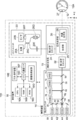
- the ophthalmology system 100 includes an ophthalmology device 110, an axial length measuring device 120, a management server device (hereinafter referred to as “server”) 140, and an image display device (hereinafter referred to as “viewer”). It has 150 and.
- the ophthalmic apparatus 110 acquires a fundus image.
- the axial length measuring device 120 measures the axial length of the patient.
- the server 140 stores the fundus image obtained by photographing the fundus of the patient by the ophthalmologic apparatus 110, corresponding to the ID of the patient.
- the viewer 150 displays medical information such as a fundus image acquired from the server 140.
- the ophthalmic apparatus 110, the axial length measuring instrument 120, the server 140, and the viewer 150 are connected to each other via the network 130.
- SLO scanning laser ophthalmoscope
- OCT optical coherence tomography
- the horizontal direction is the "X direction” and the direction perpendicular to the horizontal plane is the "Y direction", connecting the center of the pupil of the anterior segment of the eye 12 to the center of the eyeball.
- the direction is "Z direction”. Therefore, the X, Y, and Z directions are perpendicular to each other.
- the ophthalmic device 110 includes a photographing device 14 and a control device 16.
- the photographing device 14 includes an SLO unit 18, an OCT unit 20, and a photographing optical system 19, and acquires a fundus image of the fundus of the eye to be inspected 12.
- the two-dimensional fundus image acquired by the SLO unit 18 is referred to as an SLO image.
- a tomographic image of the retina, an frontal image (en-face image), or the like created based on the OCT data acquired by the OCT unit 20 is referred to as an OCT image.
- the control device 16 includes a computer having a CPU (Central Processing Unit) 16A, a RAM (Random Access Memory) 16B, a ROM (Read-Only memory) 16C, and an input / output (I / O) port 16D. ing.
- CPU Central Processing Unit
- RAM Random Access Memory
- ROM Read-Only memory
- I / O input / output
- the control device 16 includes an input / display device 16E connected to the CPU 16A via the I / O port 16D.
- the input / display device 16E has a graphic user interface for displaying an image of the eye 12 to be inspected and receiving various instructions from the user.
- the graphic user interface includes a touch panel display.
- control device 16 includes an image processing device 16G connected to the I / O port 16D.
- the image processing device 16G generates an image of the eye 12 to be inspected based on the data obtained by the photographing device 14.
- the control device 16 includes a communication interface (I / F) 16F connected to the I / O port 16D.
- the ophthalmic apparatus 110 is connected to the axial length measuring instrument 120, the server 140, and the viewer 150 via the communication interface (I / F) 16F and the network 130.
- the control device 16 of the ophthalmic device 110 includes the input / display device 16E, but the technique of the present disclosure is not limited to this.
- the control device 16 of the ophthalmic apparatus 110 may not include the input / display device 16E, but may include an input / display device that is physically independent of the ophthalmic apparatus 110.
- the display device includes an image processing processor unit that operates under the control of the CPU 16A of the control device 16.
- the image processing processor unit may display an SLO image or the like based on the image signal output instructed by the CPU 16A.
- the photographing device 14 operates under the control of the CPU 16A of the control device 16.
- the photographing apparatus 14 includes an SLO unit 18, a photographing optical system 19, and an OCT unit 20.
- the photographing optical system 19 includes a first optical scanner 22, a second optical scanner 24, and a wide-angle optical system 30.
- the first optical scanner 22 two-dimensionally scans the light emitted from the SLO unit 18 in the X direction and the Y direction.
- the second optical scanner 24 two-dimensionally scans the light emitted from the OCT unit 20 in the X direction and the Y direction.
- the first optical scanner 22 and the second optical scanner 24 may be any optical element capable of deflecting a luminous flux, and for example, a polygon mirror, a galvano mirror, or the like can be used. Moreover, it may be a combination thereof.
- the wide-angle optical system 30 includes an objective optical system having a common optical system 28 (not shown in FIG. 2), and a compositing unit 26 that synthesizes light from the SLO unit 18 and light from the OCT unit 20.
- the objective optical system of the common optical system 28 may be a catadioptric system using a concave mirror such as an elliptical mirror, a catadioptric system using a wide-angle lens or the like, or a catadioptric system combining a concave mirror or a lens.
- a wide-angle optical system using an elliptical mirror or a wide-angle lens it is possible to photograph not only the central part of the fundus where the optic disc and the macula are present, but also the retina around the fundus where the equator of the eyeball and the vortex vein are present. It will be possible.
- the wide-angle optical system 30 enables observation in the fundus with a wide field of view (FOV: Field of View) 12A.
- the FOV 12A indicates a range that can be photographed by the photographing device 14.
- FOV12A can be expressed as a viewing angle.
- the viewing angle can be defined by an internal irradiation angle and an external irradiation angle in the present embodiment.
- the external irradiation angle is an irradiation angle in which the irradiation angle of the luminous flux emitted from the ophthalmic apparatus 110 to the eye 12 to be inspected is defined with reference to the pupil 27.
- the internal irradiation angle is an irradiation angle in which the irradiation angle of the luminous flux irradiated to the fundus of the eye is defined with reference to the center O of the eyeball.
- the external irradiation angle and the internal irradiation angle have a corresponding relationship. For example, when the external irradiation angle is 120 degrees, the internal irradiation angle corresponds to about 160 degrees. In this embodiment, the internal irradiation angle is set to 200 degrees.
- the internal irradiation angle of 200 degrees is an example of the "predetermined value" of the technology of the present disclosure.
- the SLO fundus image obtained by taking a picture with an internal irradiation angle of 160 degrees or more is referred to as a UWF-SLO fundus image.
- UWF is an abbreviation for UltraWide Field (ultra-wide-angle).
- UltraWide Field ultra-wide-angle
- the SLO system is realized by the control device 16, the SLO unit 18, and the photographing optical system 19 shown in FIG. Since the SLO system includes a wide-angle optical system 30, it enables fundus photography with a wide FOV12A.
- the SLO unit 18 includes a plurality of light sources, for example, a light source 40 for B light (blue light), a light source 42 for G light (green light), a light source 44 for R light (red light), and an IR light (infrared ray (for example, near)). It is provided with a light source 46 of infrared light)) and optical systems 48, 50, 52, 54, 56 that reflect or transmit light from light sources 40, 42, 44, 46 to guide one optical path.
- the optical systems 48, 50 and 56 are mirrors, and the optical systems 52 and 54 are beam splitters.
- B light is reflected by the optical system 48, is transmitted through the optical system 50, is reflected by the optical system 54, G light is reflected by the optical systems 50 and 54, and R light is transmitted through the optical systems 52 and 54.
- IR light is reflected by the optical systems 56 and 52 and guided to one optical path, respectively.
- the SLO unit 18 is configured to be able to switch a combination of a light source that emits laser light having a different wavelength or a light source that emits light, such as a mode that emits G light, R light, and B light, and a mode that emits infrared light.
- a light source 40 for B light (blue light) includes four light sources: a light source 40 for B light (blue light), a light source 42 for G light, a light source 44 for R light, and a light source 46 for IR light.
- the SLO unit 18 may further include a light source for white light and emit light in various modes such as a mode in which only white light is emitted.
- the light incident on the photographing optical system 19 from the SLO unit 18 is scanned in the X direction and the Y direction by the first optical scanner 22.
- the scanning light is applied to the back eye portion of the eye to be inspected 12 via the wide-angle optical system 30 and the pupil 27.
- the reflected light reflected by the fundus is incident on the SLO unit 18 via the wide-angle optical system 30 and the first optical scanner 22.
- the SLO unit 18 is a beam splitter 64 that reflects B light and transmits other than B light among the light from the rear eye portion (for example, the fundus of the eye) of the eye 12 to be examined, and G of the light that has passed through the beam splitter 64.
- a beam splitter 58 that reflects light and transmits light other than G light is provided.
- the SLO unit 18 includes a beam splitter 60 that reflects R light and transmits other than R light among the light transmitted through the beam splitter 58.
- the SLO unit 18 includes a beam splitter 62 that reflects IR light among the light transmitted through the beam splitter 60.
- the SLO unit 18 includes a plurality of photodetecting elements corresponding to a plurality of light sources.
- the SLO unit 18 includes a B light detection element 70 that detects B light reflected by the beam splitter 64, and a G light detection element 72 that detects G light reflected by the beam splitter 58.
- the SLO unit 18 includes an R light detection element 74 that detects the R light reflected by the beam splitter 60, and an IR light detection element 76 that detects the IR light reflected by the beam splitter 62.
- the light incident on the SLO unit 18 via the wide-angle optical system 30 and the first optical scanner 22 (reflected light reflected by the fundus of the eye) is reflected by the beam splitter 64 and is reflected by the B light detection element 70.
- the beam splitter 64 In the case of G light, it is transmitted through the beam splitter 64, reflected by the beam splitter 58, and received by the G light detection element 72.
- the incident light passes through the beam splitters 64 and 58, is reflected by the beam splitter 60, and is received by the R light detection element 74.
- the incident light passes through the beam splitters 64, 58, and 60, is reflected by the beam splitter 62, and is received by the IR photodetector 76.
- the image processing device 16G which operates under the control of the CPU 16A, uses the signals detected by the B photodetector 70, the G photodetector 72, the R photodetector 74, and the IR photodetector 76 to produce a UWF-SLO image. Generate.
- the UWF-SLO image (also referred to as a UWF fundus image or an original fundus image as described later) includes a UWF-SLO image (G color fundus image) obtained by photographing the fundus in G color and a fundus in R color. There is a UWF-SLO image (R color fundus image) obtained by taking a picture.
- the UWF-SLO images include a UWF-SLO image (B color fundus image) obtained by photographing the fundus in B color and a UWF-SLO image (IR fundus image) obtained by photographing the fundus in IR. There is.
- control device 16 controls the light sources 40, 42, and 44 so as to emit light at the same time.
- a G color fundus image, an R color fundus image, and a B color fundus image in which the positions correspond to each other can be obtained.
- An RGB color fundus image can be obtained from the G color fundus image, the R color fundus image, and the B color fundus image.
- the control device 16 controls the light sources 42 and 44 so as to emit light at the same time, and the fundus of the eye to be inspected 12 is simultaneously photographed by the G light and the R light, so that the G color fundus image and the R color corresponding to each other at each position are taken.
- a fundus image can be obtained.
- An RG color fundus image can be obtained from the G color fundus image and the R color fundus image.
- each image data of the UWF-SLO image is transmitted from the ophthalmologic device 110 to the server 140 via the communication interface (I / F) 16F together with the patient information input via the input / display device 16E.
- Each image data of the UWF-SLO image and the patient information are stored in the storage device 254 correspondingly.
- the patient information includes, for example, patient name ID, name, age, visual acuity, right eye / left eye distinction, and the like.
- the patient information is input by the operator via the input / display device 16E.
- the OCT system is realized by the control device 16, the OCT unit 20, and the photographing optical system 19 shown in FIG. Since the OCT system includes the wide-angle optical system 30, it enables fundus photography with a wide FOV12A in the same manner as the above-mentioned SLO fundus image acquisition.
- the OCT unit 20 includes a light source 20A, a sensor (detection element) 20B, a first optical coupler 20C, a reference optical system 20D, a collimating lens 20E, and a second optical coupler 20F.
- the light emitted from the light source 20A is branched by the first optical coupler 20C.
- One of the branched lights is made into parallel light by the collimated lens 20E as measurement light, and then incident on the photographing optical system 19.
- the measurement light is scanned in the X and Y directions by the second optical scanner 24.
- the scanning light is applied to the fundus through the wide-angle optical system 30 and the pupil 27.
- the measurement light reflected by the fundus is incident on the OCT unit 20 via the wide-angle optical system 30 and the second optical scanner 24, and passes through the collimating lens 20E and the first optical coupler 20C to the second optical coupler 20F. Incident in.
- the other light emitted from the light source 20A and branched by the first optical coupler 20C is incident on the reference optical system 20D as reference light, and is incident on the second optical coupler 20F via the reference optical system 20D. To do.
- the image processing device 16G that operates under the control of the CPU 16A generates an OCT image such as a tomographic image or an en-face image based on the OCT data detected by the sensor 20B.
- OCT fundus image data can be acquired at a shooting angle of view of less than 160 degrees with an internal irradiation angle.
- the image data of the UWF-OCT image is transmitted from the ophthalmic apparatus 110 to the server 140 via the communication interface (I / F) 16F together with the patient information.
- the image data of the UWF-OCT image and the patient information are stored in the storage device 254 in correspondence with each other.
- the light source 20A exemplifies a wavelength sweep type SS-OCT (Swept-Source OCT), but SD-OCT (Spectral-Domain OCT), TD-OCT (Time-Domain OCT), etc. It may be an OCT system of various types.
- the axial length measuring device 120 has two modes, a first mode and a second mode, for measuring the axial length, which is the length of the eye to be inspected 12 in the axial direction.
- a first mode after guiding the light from a light source (not shown) to the eye 12 to be inspected, the interference light between the reflected light from the fundus and the reflected light from the cornea is received, and the interference signal indicating the received interference light is generated.
- the axial length is measured based on this.
- the second mode is a mode in which the axial length is measured using ultrasonic waves (not shown).
- the axial length measuring device 120 transmits the axial length measured by the first mode or the second mode to the server 140.
- the axial length may be measured in the first mode and the second mode.
- the average of the axial lengths measured in both modes is transmitted to the server 140 as the axial length.
- the server 140 stores the axial length of the patient corresponding to the patient name ID.
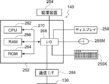
- the server 140 includes a computer main body 252.
- the computer body 252 has a CPU 262, a RAM 266, a ROM 264, and an input / output (I / O) port 268 that are interconnected by a bus 270.
- a storage device 254, a display 256, a mouse 255M, a keyboard 255K, and a communication interface (I / F) 258 are connected to the input / output (I / O) port 268.
- the storage device 254 is composed of, for example, a non-volatile memory.
- the input / output (I / O) port 268 is connected to the network 130 via the communication interface (I / F) 258. Therefore, the server 140 can communicate with the ophthalmic apparatus 110 and the viewer 150.
- An image processing program described later is stored in the storage device 254. The image processing program may be stored in the ROM 264.
- the image processing program is an example of the "program” of the technology of the present disclosure.
- the storage device 254 and ROM 264 are examples of the “memory” and “computer-readable storage medium” of the technology of the present disclosure.
- the CPU 262 is an example of a "processor" of the technology of the present disclosure.
- the processing unit 208 stores each data received from the ophthalmic device 110 in the storage device 254. Specifically, the processing unit 208 stores each image data of the UWF-SLO image, the image data of the UWF-OCT image, and the patient information (patient name ID and the like as described above) in the storage device 254 in correspondence with each other. To do. Further, when the patient's eye to be inspected has a lesion or an operation is performed on the lesion portion, the lesion information is input via the input / display device 16E of the ophthalmic apparatus 110 and transmitted to the server 140. The lesion information is stored in the storage device 254 in association with the patient information. The lesion information includes information on the position of the lesion, the name of the lesion, and the name of the surgery and the date and time of the surgery if the lesion has been operated on.
- the viewer 150 includes a computer and a display equipped with a CPU, RAM, ROM, etc., and an image processing program is installed in the ROM. Based on the user's instruction, the computer uses the fundus image acquired from the server 140, etc. Control the display so that the medical information of is displayed.
- the image processing program has a display control function, an image processing function (vortex vein analysis function, a comparative image generation function), and a processing function.
- the CPU 262 executes an image processing program having each of these functions, the CPU 262 has a display control unit 204, an image processing unit 206 (vortex vein analysis unit 2060, a comparative image generation unit 2062), and a comparison image generation unit 2062, as shown in FIG. It functions as a processing unit 208.
- the image processing by the server 140 will be described in detail with reference to FIG.
- the CPU 262 of the server 140 executes the image processing program, the image processing shown in the flowchart of FIG. 5 is realized.
- the image processing when the UWF fundus image (UWF-SLO image) is acquired by the ophthalmologic apparatus 110 and transmitted to the server 140 together with the patient name ID, and the server 140 receives the patient name ID and the UWF fundus image, Start.
- step 502 the processing unit 208 acquires the UWF fundus image G1 (note that the RGB color fundus image is shown in FIG. 8) from the storage device 254.
- step 504 the processing unit 208 generates a choroidal blood vessel image as follows.
- the structure of the eye is such that the vitreous body is covered with multiple layers having different structures.
- the layers include the retina, choroid, and sclera from the innermost to the outermost side of the vitreous body.
- R light passes through the retina and reaches the choroid. Therefore, the R-color fundus image includes information on blood vessels existing in the retina (retinal blood vessels) and information on blood vessels existing in the choroid (choroidal blood vessels).
- G light reaches only the retina. Therefore, the G-color fundus image contains only information on blood vessels (retinal blood vessels) existing in the retina.
- the processing unit 208 extracts retinal blood vessels from the G-color fundus image by applying a black hat filter process to the G-color fundus image. Next, the processing unit 208 removes the retinal blood vessels by inpainting processing using the retinal blood vessels extracted from the G color fundus image from the R color fundus image. That is, the retinal blood vessel structure of the R color fundus image is filled with the same value as the surrounding pixels by using the position information of the retinal blood vessels extracted from the G color fundus image.
- the processing unit 208 applies adaptive histogram equalization processing (CLAHE, Contrast Limited Adaptive Histogram Evaluation) to the image data of the R color fundus image from which the retinal blood vessels have been removed, so that the choroidal blood vessels in the R color fundus image.
- CLAHE Contrast Limited Adaptive Histogram Evaluation
- FIG. 9 a choroidal blood vessel image G2 is obtained.
- the generated choroidal blood vessel image is stored in the storage device 254.
- the choroidal blood vessel image is generated from the R color fundus image and the G color fundus image, and the processing unit 208 uses the R color fundus image, the R color fundus image, or the IR fundus image taken with IR light to generate the choroidal membrane.
- a blood vessel image may be generated.
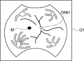
- step 506 the vortex vein analysis unit 2060 analyzes the choroidal blood vessel image and detects the position of the vortex vein. Then, the positional relationship between the vortex vein position and the fundus structure such as the macula and the optic nerve head is analyzed.
- step 506 the detection process of the vortex vein (Vortex Vein) in step 506 will be described.
- step 602 the vortex vein analysis unit 2060 reads the choroidal blood vessel image from the storage device 254.
- step 604 the vortex vein analysis unit 2060 detects the position of the vortex vein as follows.
- the vortex vein is an outflow route of blood flow that has flowed into the choroid, and there are 4 to 6 veins near the posterior pole of the equator of the eyeball.
- the position of the vortex vein is calculated based on the traveling direction of the choroidal blood vessel. This is a calculation method based on the fact that every time a choroidal blood vessel is traced, it is connected to a vortex vein, which is an outflow tract.
- the position of the vortex vein is defined as the position where a plurality of blood vessels meet by tracing the traveling direction of the blood vessel from the choroidal blood vessel image.
- the vortex vein analysis unit 2060 sets the moving direction (blood vessel traveling direction) of each choroidal blood vessel in the choroidal blood vessel image G2. Specifically, first, the vortex vein analysis unit 2060 executes the following processing for each pixel of the choroidal blood vessel image. That is, the vortex vein analysis unit 2060 sets a region (cell) centered on the pixel for the pixel, and creates a histogram in the gradient direction of the brightness of each pixel in the cell. Next, the vortex vein analysis unit 2060 sets the gradient direction with the smallest count in the histogram in each cell as the movement direction in the pixels in each cell. This gradient direction corresponds to the blood vessel traveling direction. The gradient direction with the lowest count is the blood vessel traveling direction for the following reasons.
- the brightness gradient is small in the blood vessel traveling direction, while the brightness gradient is large in the other directions (for example, the difference in brightness between the blood vessel and the non-blood vessel is large). Therefore, if a histogram of the brightness gradient of each pixel is created, the count with respect to the blood vessel traveling direction becomes small.
- the blood vessel traveling direction in each pixel of the choroidal blood vessel image is set.
- the vortex vein analysis unit 2060 estimates the position of the vortex vein. Specifically, the vortex vein analysis unit 2060 performs the following processing for each of the L positions. That is, the vortex vein analysis unit 2060 acquires the blood vessel traveling direction at the initial position (any of L), moves the virtual particles by a predetermined distance along the acquired blood vessel traveling direction, and at the moved position, The blood vessel traveling direction is acquired again, and the virtual particles are moved along the acquired blood vessel traveling direction by a predetermined distance. In this way, moving a predetermined distance along the blood vessel traveling direction is repeated for a preset number of movements. The above processing is executed at all L positions. The position of the vortex vein is the point where a certain number or more of virtual particles are gathered at that time. FIG. 10 shows how VV4 was detected from the four vortex veins VV1.
- the position information of the vortex veins (the number of vortex veins, the coordinates on the choroidal blood vessel image, etc.) is stored in the storage device 254.
- step 606 the vortex vein analysis unit 2060 reads the choroidal blood vessel image G2 and the G color fundus image from the storage device 254.
- step 608 the vortex vein analysis unit 2060 detects the respective positions (coordinates) of the macula and the optic nerve head.
- the macula is a dark area in the G-color fundus image. Therefore, the vortex vein analysis unit 2060 detects the region of a predetermined number of pixels having the smallest pixel value in the read G-color fundus image as the position of the macula.
- the vortex vein analysis unit 2060 detects the position of the optic nerve head from the G-color fundus image. Specifically, the vortex vein analysis unit 2060 detects the optic nerve head in the G-color fundus image by pattern matching the image of the optic nerve head that is predetermined with respect to the read-out G-color fundus image. Further, since the optic nerve head is the brightest region in the G-color fundus image, the region of a predetermined number of pixels having the largest pixel value in the read-out G-color fundus image may be detected as the position of the optic nerve head.
- the choroidal blood vessel image is created by processing the R color fundus image and the G color fundus image as described above. Therefore, when the coordinate system of the G fundus image is superimposed on the coordinate system of the choroidal blood vessel image, each position of the coordinate system of the G fundus image is the same as each position of the coordinate system of the choroidal blood vessel image. Therefore, each position on the choroidal blood vessel image corresponding to each position of the macula and the optic nerve head detected from the G-color fundus image is the position of each of the macula and the optic nerve head.
- the position of the macula may be detected from the choroidal blood vessel image instead of the G-color fundus image.
- the position of the optic nerve head may be detected from the choroidal fundus image instead of the G-color fundus image.
- the vortex vein analysis unit 2060 calculates the relative position of each of the detected vortex veins (the positional relationship between the vortex vein and the fundus structure such as the macula and the optic nerve head).
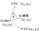
- the vortex vein VV3 has an angle ⁇ between the first line connecting the optic nerve head ONH and the macula M and the second line connecting the optic nerve head ONH and the vortex vein (for example, VV3).
- the positional relationship is such that the distance r between the vortex vein VV3 and the optic disc ONH.
- the vortex vein analysis unit 2060 calculates the positional relationship.
- the vortex vein VV3 is the angle formed by the first line connecting the optic disc ONH and the macula M, the first line, and the third line connecting the macula M and the macula VV3.
- the set of the angle ⁇ and the distance r, and the set of the angle ⁇ and the distance s are examples of the “first set” and the “second set” of the techniques of the present disclosure.
- the vortex vein analysis unit 2060 calculates the angle ⁇ , the distance r, the angle ⁇ , and the distance s for each vortex vein.
- the calculation method of the angle ⁇ and the distance s is substantially the same as the calculation method of the angle ⁇ and the distance r, except that the macula M is used as a reference instead of the optic disc ONH. Therefore, the calculation method of the angle ⁇ and the distance r will be described below, and the description of the calculation method of the angle ⁇ and the distance s will be omitted.
- VV distance the distance between the vortex vein (hereinafter referred to as VV) and the optic nerve head ONH.
- step 221 the vortex vein analysis unit 2060 acquires the coordinates of the optic disc ONH, macula M, and VV positions in the choroidal fundus image.
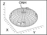
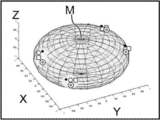
- the vortex vein analysis unit 2060 projects the coordinates of the optic disc ONH, macula M, and VV positions onto the virtual sphere shown in FIG.
- the virtual sphere shown in FIG. 13 is a sphere in which the center of the eyeball is C and the radius is L (the axial length is 2L).
- the position of VV is projected as V, the position of the optic disc ONH as O, and the position of the macula as M on this spherical surface.
- the vortex vein analysis unit 2060 calculates the great circle distance between two points on the sphere as the VV distance r. That is, the great circle is defined as the cut end when the sphere is cut so as to pass through the center O of the sphere, and the great circle distance is the two points (VV position: V and the optic nerve papilla position: V) to be measured on the sphere. It is defined as the length of the arc of the great circle connecting O).
- the vortex vein analysis unit 2060 will perform in this step 223.
- the VV distance r between the VV position and the papilla position of the optic nerve, that is, the great circle distance OV is calculated from the formula of the spherical triangle method.
- step 227 the vortex vein analysis unit 2060 stores the calculated VV distance r, that is, the VV distance r (great circle distance OV) between the VV position and the optic disc position in the storage device 254.
- the VV angle is the angle ⁇ formed by the position of the macula M-the position of the optic disc ONH-the position of the VV.
- the vortex vein analysis unit 2060 calculates the left and right eye adjustment code f sign. As shown in FIG. 11, the position of the macula M is (x 1 , y 1 ), the position of the optic disc ONH is (x 2 , y 2 ), and the position of VV is (x 3 , y 3 ).
- the left and right eye adjustment code f sign is
- the vortex vein analysis unit 2060 calculates cos ⁇ and sin ⁇ using Equations 2 and 3 based on the definitions of the inner and outer products of the vectors.
- the angle ⁇ formed by the position of the spot M-the position of the optic disc ONH-the position of the VV is a vector OM (a vector connecting the optic disc position O and the macula position M) and a vector OV (the optic disc position O and the vortex vein position V). It is the angle formed by the vector that connects the two.
- step 226 the vortex vein analysis unit 2060 calculates ⁇ by the 4-quadrant inverse tangent function as follows.
- the ⁇ obtained by the 4-quadrant inverse tangent function considers not only the y / x value but also the sign of each x in the 4-quadrant.
- step 228, the vortex vein analysis unit 2060 corrects the calculated ⁇ code using f sign as follows.
- step 230 the vortex vein analysis unit 2060 stores the value of ⁇ thus obtained in the storage device 254 as a VV angle.
- the position M of the macula, the position O of the optic nerve head ONH, and the position V of VV are located on the surface of a sphere having a radius L when the center of the eye is C and the axial length is 2L. ..
- ⁇ be the angle of the apex angle O of the triangle OMV whose apex is the position M of the macula, the position O of the optic disc ONH, and the position V of the VV.
- ⁇ (however, ⁇ is within the range of [0, ⁇ ]) can be calculated.
- g sign positional relationship between the macula M and the optic disc ONH, the positional relationship between the VV position V and the macula M
- ⁇ ⁇ ⁇ g sign
- the image processing program includes either a program for calculating the VV angle from the conformal projection shown in FIG. 7B or a program for calculating the VV angle from the above spherical trigonometry.
- step 506 of FIG. 5 the analysis process of the vortex vein of FIG. 6 (step 506 of FIG. 5) is completed, and the image processing proceeds to step 508.
- step 508 the processing unit 208 reads out the data related to the past image corresponding to the patient name ID.
- the data on the past image corresponding to the patient name ID is the relative position of the vortex vein based on the past UWF fundus image corresponding to the patient name ID.
- the data related to the past image is the data in which the image processing of FIG. 5 is executed and stored in the past at a timing different from this time.
- the "first position” and “second position” of the technique of the present disclosure are not limited to the above relative positions, and may be specified by the coordinates where the vortex vein is located.
- step 510 the comparative image generation unit 2062 generates vortex vein map data.
- the vortex vein map is a map obtained by plotting the positions of vortex veins extracted from a plurality of fundus images taken at different timings (dates and times). Since the positions of the vortex veins extracted from the plurality of fundus images taken at different timings are plotted on the map, the ophthalmologist and the like can refer to the newly taken UWF fundus images by looking at the map. The relative position of the vortex vein can be compared with the relative position of the vortex vein based on past UWF fundus images.
- the relative position of the vortex vein based on the UWF fundus image this time is the relative position of the vortex vein based on the UWF fundus image acquired this time after the image processing was executed this time.
- the relative position of the vortex vein based on the past UWF fundus image is the relative position of the vortex vein based on the past UWF fundus image corresponding to the patient name ID read in step 508.
- the relative positions of the vortex veins are the angle ⁇ and the distance r with respect to the optic disc ONH and the angle ⁇ and the distance s with respect to the macula M as shown in FIG. 15A. Is specified by.
- the vortex vein map using the angle ⁇ and the distance r For example, in the vortex vein map using the angle ⁇ and the distance r, first, the positions of the vortex veins this time and in the past are displayed in a polar coordinate system using the angle ⁇ and the distance r as shown in FIG. 14B. There is a map (radar chart). Secondly, the vortex vein map includes a map in which the positions of the vortex veins this time and in the past are displayed in a two-dimensional Cartesian coordinate system using an angle ⁇ and a distance r as shown in FIG. 14C. Third, the vortex vein map includes a map in which the positions of the vortex veins this time and in the past are displayed in a three-dimensional Cartesian coordinate system using an angle ⁇ and a distance r, as shown in FIG.
- the map displayed in the two-dimensional Cartesian coordinate system shown in FIG. 14C is an example of the “scattering diagram defined by the two-dimensional orthogonal axis” of the technique of the present disclosure, and the map displayed in the three-dimensional Cartesian coordinate system shown in FIG. 14D. Is an example of the "scattering diagram defined by the three-dimensional orthogonal axis" of the technique of the present disclosure.
- the comparative image generation unit 2062 generates the data of each map of FIGS. 14B to 14D as follows.
- Each map of FIGS. 14B to 14D is generated by plotting the relative positions of the vortex veins based on the current UWF fundus image with " ⁇ ", and the UWF fundus images obtained in the past three fundus photographs.
- the relative position of the vortex vein based on is created by plotting with " ⁇ ", " ⁇ ", and " ⁇ ".
- the center of the eyeball is the center (0.00) of the three dimensions (X, Y, Z), and the apex (0.0.1) is the optic disc ONH.
- the position of. In the map of the three-dimensional Cartesian coordinate system, the positions of the vortex veins specified by the angle ⁇ and the distance r are plotted at the positions corresponding to the angle ⁇ and the distance r in the eyeball model.
- the size of the eyeball model is corrected by the axial length.
- FIGS. 15B to 15D the vortex vein map using the angle ⁇ and the distance s is shown in FIGS. 15B to 15D. Since each map of FIGS. 15B to 15D corresponds to each map of FIGS. 14B to 14D, the description thereof will be omitted.
- the processing unit 208 corresponds the UWF fundus image, the choroidal fundus image, the position of each vortex vein (angle ⁇ , distance r, angle ⁇ , and distance s), and the data of each map to the patient name ID. And store it in the storage device 254.
- the image processing of FIG. 5 is executed every time the server 140 receives the patient name ID and the UWF fundus image from the ophthalmic apparatus 110.
- the technique of the present disclosure is not limited to this, and for example, the image processing may be executed when the operator inputs the patient name ID and the start button (not shown) is operated. Even if the server 140 receives the UWF fundus image from the ophthalmic apparatus 110, there is an embodiment in which the UWF fundus image in which the relative position of the vortex vein is not calculated exists.
- step 502 the processing unit 208 acquires the UWF fundus image G1 from which the relative position of the vortex vein has not been calculated from the storage device 254.
- steps 504 and 506 are executed for each of the acquired UWF fundus images G1.
- steps 504 and 506 are performed for all UWF fundus images G1 corresponding to the patient name ID, regardless of whether the relative position of the vortex vein has been calculated.
- the ophthalmologist inputs the patient name ID into the viewer 150 when examining the patient's eye to be examined.
- the viewer 150 instructs the server 140 to transmit each data corresponding to the patient name ID.
- the server 140 displays the patient name, the patient's age, the patient's visual acuity, the information on whether the left eye or the right eye, the axial length, the imaging date, and each data corresponding to the patient name ID together with the patient name ID in the viewer 150.
- Each data includes the above UWF fundus image, choroidal fundus image, position of each vortex vein (angle ⁇ , distance r, angle ⁇ , and distance s), and screen data of each map.
- the viewer 150 which received the patient name ID, the patient name, the patient's age, the patient's visual acuity, the information on whether the left eye or the right eye, the axial length, the shooting date, and the data, is the first fundus image shown in FIG.
- the display screen 1000A is displayed on the display.
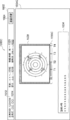
- the first fundus image display screen 1000A includes a patient information display field 1002 and a first fundus image information display field 1004A.
- the first fundus image information display field 1004A is an example of the "display view" of the technique of the present disclosure.
- the patient information display field 1002 is a screen with each display field 1012 to 1022 for displaying the patient name ID, the patient name, the patient's age, the patient's visual acuity, the information on whether the left eye or the right eye, and the axial length. It has a switching button 1024. In the display fields 1012 to 1022, the received patient name ID, patient name, patient age, patient's visual acuity, left eye or right eye information, and axial length are displayed.
- the first fundus image information display field 1004A includes a UWF fundus image display field 1032A, a choroidal blood vessel image display field 1032B, and current and past choroidal blood vessel image display fields 1035BT4 to 1035BT1, a slider 1037, and a slider bar 1035.
- the first fundus image information display field 1004A includes a vortex vein map display field 1032C, a VV map switching button 1036, and an information display field 1034.
- the data of the imaging date and time (YYY / MM / DD) in which the fundus was photographed is displayed.
- the UWF fundus image and the choroidal blood vessel image obtained by photographing the fundus at the time closest to the present are initially displayed.
- the UWF fundus image, that is, the original fundus image is, for example, an RGB color fundus image.
- the UWF fundus image and choroidal blood vessel image obtained by photographing the fundus at the imaging date and time when the slider 1037 is located are displayed in the UWF fundus image display column 1032A and the choroidal blood vessel image display column 1032B. Is displayed.
- the vortex vein map is displayed in the vortex vein map display field 1032C. Specifically, when the VV map switching button 1036 is operated, a pull-down menu 1036PDM for selecting a vortex vein map (FIGS. 14B to 14D and 15B to 15D) is displayed.
- the pull-down menu 1036PDM includes 6 of "Radar chart optic disc center”, “Radar chart macular center”, “Plot diagram optic disc center”, “Plot diagram optic disc center”, “3D optic disc center”, and “3D macular center”. Contains items.
- Radar chart optic disc center When "Radar chart optic disc center" is selected, as shown in FIG. 14B, a map (radar chart) displayed in a polar coordinate system using an angle ⁇ and a distance r with respect to the optic disc ONH is displayed. Is selected.
- Radar chart center of macula When “Radar chart center of macula” is selected, as shown in FIG. 15B, it is selected that a map (radar chart) displayed in a polar coordinate system using an angle ⁇ and a distance r with respect to the macula M is displayed. Will be done.
- a radar chart centered on the optic nerve head is selected in the pull-down menu 1036PDM, the shooting date and time when the slider 1037 is located in the vortex vein map display field 1032C.
- a radar chart centered on the optic nerve head is displayed.
- the corresponding vortex vein map is displayed, and the displayed vortex vein map displays the relative positions of all the plurality of vortex veins (4 in the above example).
- the techniques of the present disclosure are not limited to this.
- the vortex vein map shows the relative position of one vortex vein selected from the plurality of vortex veins. For example, in the example shown in FIG. 16, for example, the ophthalmologist selects one vortex vein from the four vortex veins displayed in the UWF fundus image display field 1032A. For example, when the upper left vortex vein is selected, the relative position of only the selected vortex vein is displayed in the vortex vein map display field 1032C.
- the technique of the present disclosure is not limited to the ophthalmologist selecting a single vortex vein from the four vortex veins.
- the viewer 150 selects vortex veins one by one in a predetermined order for four vortex veins, for example, in the order of upper left, upper right, lower right, and lower left, and selects them in the vortex vein map display field 1032C.
- the relative position of only the vortex vein that has been created is displayed.
- two vortex veins may be selected so that the relative positions of the two selected vortex veins are displayed.
- the position of the upper left vortex vein and the position of the lower left vortex vein are symmetrical with respect to the line segment connecting the macula and the optic nerve head during the follow-up period. It is possible to easily determine whether the sex is maintained or whether the symmetry is broken and the asymmetry is formed from a certain point.
- the size of the current and past choroidal blood vessel image display fields 1035BT4 to 1035BT1 is smaller than the size of the UWF fundus image display field 1032A and the choroidal blood vessel image display field 1032B.
- the size of the vortex vein map display field 1032C is smaller than the size of the UWF fundus image display field 1032A and the choroidal blood vessel image display field 1032B.
- the viewer 150 displays the second fundus image display screen 1000B shown in FIG. 17 on the display.
- first fundus image display screen 1000A and the second fundus image display screen 1000B have substantially the same contents, the same parts are designated by the same reference numerals, the description thereof will be omitted, and only the different parts will be described.
- the size of the vortex vein map display field 1032C of the fundus image information display field 1004B of the second fundus image display screen 1000B is larger than the size of the vortex vein map display field 1032C of FIG.
- the position of the vortex vein map display column 1032C of the second fundus image display screen 1000B is different from the position of the vortex vein map display column 1032C of FIG.
- the viewer 150 changes the color of the plot to another color and is detected from the same choroidal blood vessel image.
- the color of the plot of the position of the other vortex vein is also changed to the other color.
- the viewer 150 moves the slider 1037 so as to correspond to the shooting date and time corresponding to the plot.
- the viewer 150 displays the UWF fundus image and the choroidal blood vessel image obtained by photographing the fundus at the imaging date and time when the slider 1037 is located in the UWF fundus image display column 1032A and the choroidal blood vessel image display column 1032B.
- the viewer 150 displays the second fundus image display screen 1000C shown in FIG. 18 on the display.
- the third fundus image information display field 1004C of the third fundus image display screen 1000C includes only the vortex vein map display field 1038, the color bar 1035C, and the information display field 1034.
- the vortex vein map display field 1038 for example, a map (FIG. 15C) in which the positions of the vortex veins this time and in the past are displayed in a two-dimensional Cartesian coordinate system centered on the macula is displayed.
- any plot eg, " ⁇ "
- the viewer 150 changes the color of the plot to another color and the other vortex detected from the same choroidal vessel image.
- the color of the plot of the position of the blood vessel is also changed to the other color.
- the viewer 150 displays the shooting date and time corresponding to the selected plot (for example, ".") In the upper left of the vortex vein map display field 1038.
- the viewer 150 changes the color of the color bar 1035C from the current (left end) to the shooting date and time of ".”.
- the comparison map comparing the positions of the vortex veins obtained from each fundus image in the past from this time is displayed, the change in the position of the vortex veins can be displayed in an easy-to-understand manner. .. Therefore, the follow-up of the vortex vein position can be performed, and the change in the vortex vein position can be displayed in an easy-to-understand manner for the user.
- the viewer 150 may also display the following information. For example, as shown in FIG. 19, the viewer 150 first displays the centers C1 to C4 at the four positions of the vortex vein at each imaging date and time, and secondly displays the center CCs of the centers C1 to C4.
- a graph showing the time change of the distances r and s to each vortex vein at each imaging date and time may be displayed.
- the position of the vortex vein is specified by the set of the angle ⁇ and the distance r, the angle ⁇ and the distance s, but the technique of the present disclosure is not limited to this.
- the correspondence between the position of each pixel in the choroidal fundus image and the position (X, Y, Z) in the three-dimensional space is obtained in advance.
- the position of the vortex vein in the three-dimensional space is specified from the corresponding relationship, and the above angle and distance are calculated from the position of the specified vortex vein in the three-dimensional space. ..
- the image processing of FIG. 5 is executed by the server 140, but the technology of the present disclosure is not limited to this.
- the ophthalmic apparatus 110 or the viewer 150 may execute the image processing apparatus, or another image processing apparatus may be connected to the network 130 to execute the image processing apparatus.
- image processing is realized by a software configuration using a computer
- the technology of the present disclosure is not limited to this.
- the image processing may be executed only by a hardware configuration such as FPGA (Field-Programmable Gate Array) or ASIC (Application Specific Integrated Circuit). Some of the image processing may be performed by the software configuration and the rest may be performed by the hardware configuration.
- the technique of the present disclosure includes a case where image processing is realized by a software configuration using a computer and a case where image processing is realized by a configuration other than a software configuration using a computer. Includes technology and second technology.
- the vortex vein analysis unit 2060 of the above embodiment is an example of the "specific unit” of the first technique
- the comparative image generation unit 2062 of the above embodiment is of the "generation unit” of the first technique. This is an example.
- the specific part identifies the first position of the vortex vein from the first fundus image and identifies the second position of the vortex vein from the second fundus image.
- the generation unit generates data on the screen on which the first position and the second position are displayed. Image processing method.
- a computer program product for image processing comprises a computer-readable storage medium that is not itself a temporary signal.
- the program is stored in the computer-readable storage medium.
- the program On the computer Identify the first position of the vortex vein from the first fundus image, The second position of the vortex vein was identified from the second fundus image, Generate screen data on which the first position and the second position are displayed. To do that, Computer program product.
Abstract
Description


なお、本開示の技術の「第1位置」及び「第2位置」は、上記相対位置に限定されず、渦静脈の位置する座標で特定されてもよい。 The relative position of the vortex vein based on the current UWF fundus image obtained by performing the image processing of FIG. 5 this time, and the relative position of the vortex vein based on the past image obtained by performing the image processing of FIG. 5 in the past. Is an example of the "first position" and the "second position" of the technique of the present disclosure.
The "first position" and "second position" of the technique of the present disclosure are not limited to the above relative positions, and may be specified by the coordinates where the vortex vein is located.
図14Cに示す2次元直交座標系で表示したマップは、本開示の技術の「2次元直交軸で規定される散布図」の一例であり、図14Dに示す3次元直交座標系で表示したマップは、本開示の技術の「3次元直交軸で規定される散布図」の一例である。
比較画像生成部2062は、図14Bから図14Dの各マップのデータを、次のように、生成する。 For example, in the vortex vein map using the angle θ and the distance r, first, the positions of the vortex veins this time and in the past are displayed in a polar coordinate system using the angle θ and the distance r as shown in FIG. 14B. There is a map (radar chart). Secondly, the vortex vein map includes a map in which the positions of the vortex veins this time and in the past are displayed in a two-dimensional Cartesian coordinate system using an angle θ and a distance r as shown in FIG. 14C. Third, the vortex vein map includes a map in which the positions of the vortex veins this time and in the past are displayed in a three-dimensional Cartesian coordinate system using an angle θ and a distance r, as shown in FIG. 14D.
The map displayed in the two-dimensional Cartesian coordinate system shown in FIG. 14C is an example of the “scattering diagram defined by the two-dimensional orthogonal axis” of the technique of the present disclosure, and the map displayed in the three-dimensional Cartesian coordinate system shown in FIG. 14D. Is an example of the "scattering diagram defined by the three-dimensional orthogonal axis" of the technique of the present disclosure.
The comparative
第1眼底画像情報表示欄1004Aは、本開示の技術の「表示ビュー」の一例である。 As shown in FIG. 16, the first fundus
The first fundus image
また、上記実施の形態では、渦静脈の位置を、角度θおよび距離rの組、角度φおよび距離sにより特定しているが、本開示の技術は、これに限定されない。例えば、脈絡膜眼底画像の各画素の位置と、3次元空間の位置(X,Y,Z)との対応関係を予め求めておく。脈絡膜血管画像から特定された渦静脈の位置から、当該対応関係から、渦静脈の3次元空間の位置を特定し、特定された渦静脈の3次元空間の位置から、上記角度及び距離を計算する。 Further, in the technique of the present disclosure, a graph showing the time change of the distances r and s to each vortex vein at each imaging date and time may be displayed.
Further, in the above embodiment, the position of the vortex vein is specified by the set of the angle θ and the distance r, the angle φ and the distance s, but the technique of the present disclosure is not limited to this. For example, the correspondence between the position of each pixel in the choroidal fundus image and the position (X, Y, Z) in the three-dimensional space is obtained in advance. From the position of the vortex vein identified from the choroidal blood vessel image, the position of the vortex vein in the three-dimensional space is specified from the corresponding relationship, and the above angle and distance are calculated from the position of the specified vortex vein in the three-dimensional space. ..
第1眼底画像から渦静脈の第1位置を特定し且つ第2眼底画像から前記渦静脈の第2位置を特定する特定部と、
前記第1位置および前記第2位置が表示される画面のデータを生成する生成部と、
を含む画像処理装置。 (First technology)
A specific part that identifies the first position of the vortex vein from the first fundus image and the second position of the vortex vein from the second fundus image,
A generation unit that generates data on the screen on which the first position and the second position are displayed, and
Image processing equipment including.
特定部が、第1眼底画像から渦静脈の第1位置を特定し且つ第2眼底画像から前記渦静脈の第2位置を特定し、
生成部が、前記第1位置および前記第2位置が表示される画面のデータを生成する、
画像処理方法。 (Second technology)
The specific part identifies the first position of the vortex vein from the first fundus image and identifies the second position of the vortex vein from the second fundus image.
The generation unit generates data on the screen on which the first position and the second position are displayed.
Image processing method.
画像処理するためのコンピュータープログラム製品であって、
前記コンピュータープログラム製品は、それ自体が一時的な信号ではないコンピュータ可読記憶媒体を備え、
前記コンピュータ可読記憶媒体には、プログラムが格納されており、
前記プログラムは、
コンピュータに、
第1眼底画像から渦静脈の第1位置を特定し、
第2眼底画像から前記渦静脈の第2位置を特定し、
前記第1位置および前記第2位置が表示される画面のデータを生成する、
ことを実行させる、
コンピュータープログラム製品。 (Third technology)
A computer program product for image processing
The computer program product comprises a computer-readable storage medium that is not itself a temporary signal.
The program is stored in the computer-readable storage medium.
The program
On the computer
Identify the first position of the vortex vein from the first fundus image,
The second position of the vortex vein was identified from the second fundus image,
Generate screen data on which the first position and the second position are displayed.
To do that,
Computer program product.
Claims (10)
- プロセッサが、第1眼底画像から渦静脈の第1位置を特定することと、
前記プロセッサが、第2眼底画像から前記渦静脈の第2位置を特定することと、
前記プロセッサが、前記第1位置および前記第2位置を表示する渦静脈マップのデータを生成することと、
を含む、画像処理方法。 The processor identifies the first position of the vortex vein from the first fundus image,
The processor identifies the second position of the vortex vein from the second fundus image, and
The processor generates data of a vortex vein map displaying the first position and the second position.
Image processing methods, including. - 前記第1眼底画像および前記第2眼底画像は、眼底を異なるタイミングで撮影した画像である、
請求項1に記載の画像処理方法。 The first fundus image and the second fundus image are images of the fundus taken at different timings.
The image processing method according to claim 1. - 前記渦静脈の前記第1位置および前記第2位置は、
眼底の第1構造物と前記第1構造物と異なる第2構造物とを結ぶ第1の線と前記第1構造物と前記渦静脈とを結ぶ第2の線との第1のなす角度、および、前記渦静脈と前記第1構造物との第1の距離の第1の組と、
前記渦静脈の前記第1位置および前記第2位置は、前記第1の線と前記第2構造物と前記渦静脈とを結ぶ第3の線との第2のなす角度、および、前記渦静脈と前記第2構造物との第2の距離の第2の組と、
の少なくとも一方により、特定される、
請求項1また請求項2に記載の画像処理方法。 The first position and the second position of the vortex vein are
The first angle between the first line connecting the first structure of the fundus and the second structure different from the first structure and the second line connecting the first structure and the vortex vein, And a first set of first distances between the vortex vein and the first structure,
The first position and the second position of the vortex vein are the second angle formed by the first line and the third line connecting the second structure and the vortex vein, and the vortex vein. And a second set of second distances to the second structure,
Identified by at least one of
The image processing method according to claim 1 or 2. - 前記渦静脈マップは、前記渦静脈の前記第1位置および前記第2位置を、前記第1の組および前記第2の組の少なくとも一方を用いた極座標系、2次元直交座標系、および3次元直交座標系の少なくとも1つの座標系で表示したマップである、
請求項3に記載の画像処理方法。 The vortex vein map is a polar coordinate system using the first position and the second position of the vortex vein at least one of the first set and the second set, a two-dimensional Cartesian coordinate system, and a three-dimensional. A map displayed in at least one coordinate system in a Cartesian coordinate system,
The image processing method according to claim 3. - 前記極座標系で表示したマップは、レーダチャートであり、
前記2次元直交座標系で表示したマップは、2次元直交軸で規定される散布図であり、
前記3次元直交座標系で表示したマップは、3次元直交軸で規定される散布図である、
請求項4に記載の画像処理方法。 The map displayed in the polar coordinate system is a radar chart.
The map displayed in the two-dimensional Cartesian coordinate system is a scatter diagram defined by the two-dimensional Cartesian axis.
The map displayed in the three-dimensional Cartesian coordinate system is a scatter diagram defined by the three-dimensional Cartesian axis.
The image processing method according to claim 4. - 前記第1眼底画像および前記第2眼底画像の各々には、複数の前記渦静脈が存在し、
前記プロセッサが、複数の前記渦静脈の中心位置を求め、
前記渦静脈マップに前記中心位置が表示される、
請求項1から請求項5の何れか1項に記載の画像処理方法。 Each of the first fundus image and the second fundus image has a plurality of the vortex veins.
The processor finds the central positions of the plurality of the vortex veins,
The center position is displayed on the vortex vein map.
The image processing method according to any one of claims 1 to 5. - 前記第1眼底画像および前記第2眼底画像の各々には、前記渦静脈が複数存在し、
前記渦静脈マップのデータは、前記複数の渦静脈から選択された渦静脈を対象として生成される、
請求項1から請求項6の何れか1項に記載の画像処理方法。 A plurality of the vortex veins are present in each of the first fundus image and the second fundus image.
The data of the vortex vein map is generated for the vortex vein selected from the plurality of vortex veins.
The image processing method according to any one of claims 1 to 6. - 前記プロセッサが、前記渦静脈マップと、前記第1眼底画像および前記第2眼底画像と、を表示する表示ビューを生成することを更に含む請求項1から請求項7の何れか1項に記載の画像処理方法。 The one according to any one of claims 1 to 7, further comprising generating a display view in which the processor displays the vortex vein map, the first fundus image and the second fundus image. Image processing method.
- メモリと、前記メモリに接続されたプロセッサとを備え、
前記プロセッサは、
第1眼底画像から渦静脈の第1位置を特定し、
第2眼底画像から前記渦静脈の第2位置を特定し、
前記第1位置および前記第2位置を表示する渦静脈マップのデータを生成する、
画像処理装置。 A memory and a processor connected to the memory are provided.
The processor
Identify the first position of the vortex vein from the first fundus image,
The second position of the vortex vein was identified from the second fundus image,
Generate vortex vein map data displaying the first position and the second position.
Image processing device. - コンピュータに、
第1眼底画像から渦静脈の第1位置を特定し、
第2眼底画像から前記渦静脈の第2位置を特定し、
前記第1位置および前記第2位置を表示する渦静脈マップのデータを生成する、
ことを実行させるプログラム。 On the computer
Identify the first position of the vortex vein from the first fundus image,
The second position of the vortex vein was identified from the second fundus image,
Generate vortex vein map data displaying the first position and the second position.
A program that lets you do things.
Priority Applications (3)
| Application Number | Priority Date | Filing Date | Title |
|---|---|---|---|
| JP2021552011A JP7416083B2 (en) | 2019-10-15 | 2019-10-15 | Image processing method, image processing device, and program |
| PCT/JP2019/040483 WO2021074962A1 (en) | 2019-10-15 | 2019-10-15 | Image processing method, image processing device, and program |
| US17/769,318 US20240127473A1 (en) | 2019-10-15 | 2019-10-15 | Image processing method, image processing device, and program |
Applications Claiming Priority (1)
| Application Number | Priority Date | Filing Date | Title |
|---|---|---|---|
| PCT/JP2019/040483 WO2021074962A1 (en) | 2019-10-15 | 2019-10-15 | Image processing method, image processing device, and program |
Publications (1)
| Publication Number | Publication Date |
|---|---|
| WO2021074962A1 true WO2021074962A1 (en) | 2021-04-22 |
Family
ID=75538696
Family Applications (1)
| Application Number | Title | Priority Date | Filing Date |
|---|---|---|---|
| PCT/JP2019/040483 WO2021074962A1 (en) | 2019-10-15 | 2019-10-15 | Image processing method, image processing device, and program |
Country Status (3)
| Country | Link |
|---|---|
| US (1) | US20240127473A1 (en) |
| JP (1) | JP7416083B2 (en) |
| WO (1) | WO2021074962A1 (en) |
Citations (4)
| Publication number | Priority date | Publication date | Assignee | Title |
|---|---|---|---|---|
| JP2008029732A (en) * | 2006-07-31 | 2008-02-14 | Nidek Co Ltd | Ophthalmological device |
| JP2014083285A (en) * | 2012-10-25 | 2014-05-12 | Canon Inc | Image processor and image processing method |
| JP2018161230A (en) * | 2017-03-24 | 2018-10-18 | 株式会社トプコン | Display control apparatus, display control method, and program |
| WO2019181981A1 (en) * | 2018-03-20 | 2019-09-26 | 株式会社ニコン | Image processing method, program, opthalmologic instrument, and choroidal blood vessel image generation method |
-
2019
- 2019-10-15 WO PCT/JP2019/040483 patent/WO2021074962A1/en active Application Filing
- 2019-10-15 JP JP2021552011A patent/JP7416083B2/en active Active
- 2019-10-15 US US17/769,318 patent/US20240127473A1/en active Pending
Patent Citations (4)
| Publication number | Priority date | Publication date | Assignee | Title |
|---|---|---|---|---|
| JP2008029732A (en) * | 2006-07-31 | 2008-02-14 | Nidek Co Ltd | Ophthalmological device |
| JP2014083285A (en) * | 2012-10-25 | 2014-05-12 | Canon Inc | Image processor and image processing method |
| JP2018161230A (en) * | 2017-03-24 | 2018-10-18 | 株式会社トプコン | Display control apparatus, display control method, and program |
| WO2019181981A1 (en) * | 2018-03-20 | 2019-09-26 | 株式会社ニコン | Image processing method, program, opthalmologic instrument, and choroidal blood vessel image generation method |
Non-Patent Citations (2)
| Title |
|---|
| MUKA MORIYAMA, KEJIA CAO, SATOKO OGATA, KYOKO OHNO-MATSUI: "Detection of posterior vortex veins in eyes with pathologic myopia by ultra-widefield indocyanine green angiography", BRITISH JOURNAL OF OPHTHALMOLOGY, vol. 101, no. Issue 9, 18 September 2017 (2017-09-18), pages 1179 - 1184 * |
| OHNO-MATSUI ' KYOKO, MORISHIMA ' NAOTO, TERAMATSU ' TOHRU, TOKORO ' TAKASHI, NAKAGAWA TSUNEAKI: "The long-term follow-up of a highly myopic patient with a macular vortex vein", ACTA OPHTHALMOLOGICA SCANDINAVICA, vol. 75, no. 3, 30 June 1997 (1997-06-30), pages 329 - 332, XP055819645 * |
Also Published As
| Publication number | Publication date |
|---|---|
| US20240127473A1 (en) | 2024-04-18 |
| JP7416083B2 (en) | 2024-01-17 |
| JPWO2021074962A1 (en) | 2021-04-22 |
Similar Documents
| Publication | Publication Date | Title |
|---|---|---|
| JP2023009530A (en) | Image processing method, image processing device, and program | |
| JP7279711B2 (en) | IMAGE PROCESSING METHOD, PROGRAM, IMAGE PROCESSING APPARATUS, AND OPHTHALMIC SYSTEM | |
| US11941788B2 (en) | Image processing method, program, opthalmic device, and choroidal blood vessel image generation method | |
| US20230084582A1 (en) | Image processing method, program, and image processing device | |
| WO2021075062A1 (en) | Image processing method, image processing device, and program | |
| JP2023158161A (en) | Image processing method, program, image processing device, and ophthalmic system | |
| WO2021074960A1 (en) | Image processing method, image processing device, and image processing program | |
| WO2020240867A1 (en) | Image processing method, image processing device, and image processing program | |
| JP7416083B2 (en) | Image processing method, image processing device, and program | |
| JP2021168759A (en) | Image processing method, image processing device, and image processing program | |
| WO2021111840A1 (en) | Image processing method, image processing device, and program | |
| US11954872B2 (en) | Image processing method, program, and image processing device | |
| WO2021210295A1 (en) | Image processing method, image processing device, and program | |
| WO2021210281A1 (en) | Image processing method, image processing device, and image processing program | |
| WO2023282339A1 (en) | Image processing method, image processing program, image processing device, and ophthalmic device | |
| WO2021074961A1 (en) | Image processing method, image processing device, and program | |
| JP7472914B2 (en) | IMAGE PROCESSING METHOD, IMAGE PROCESSING APPARATUS, AND PROGRAM | |
| WO2022177028A1 (en) | Image processing method, image processing device, and program | |
| WO2022113409A1 (en) | Image processing method, image processing device, and program | |
| JP2024059709A (en) | Image Processing Method |
Legal Events
| Date | Code | Title | Description |
|---|---|---|---|
| 121 | Ep: the epo has been informed by wipo that ep was designated in this application |
Ref document number: 19949202 Country of ref document: EP Kind code of ref document: A1 |
|
| ENP | Entry into the national phase |
Ref document number: 2021552011 Country of ref document: JP Kind code of ref document: A |
|
| NENP | Non-entry into the national phase |
Ref country code: DE |
|
| WWE | Wipo information: entry into national phase |
Ref document number: 17769318 Country of ref document: US |
|
| 122 | Ep: pct application non-entry in european phase |
Ref document number: 19949202 Country of ref document: EP Kind code of ref document: A1 |