WO2021070415A1 - Correction parameter calculation method, displacement amount calculation method, correction parameter calculation device, and displacement amount calculation device - Google Patents
Correction parameter calculation method, displacement amount calculation method, correction parameter calculation device, and displacement amount calculation device Download PDFInfo
- Publication number
- WO2021070415A1 WO2021070415A1 PCT/JP2020/023535 JP2020023535W WO2021070415A1 WO 2021070415 A1 WO2021070415 A1 WO 2021070415A1 JP 2020023535 W JP2020023535 W JP 2020023535W WO 2021070415 A1 WO2021070415 A1 WO 2021070415A1
- Authority
- WO
- WIPO (PCT)
- Prior art keywords
- imaging device
- correction parameter
- image data
- distance
- image
- Prior art date
Links
- 238000006073 displacement reaction Methods 0.000 title claims abstract description 421
- 238000012937 correction Methods 0.000 title claims abstract description 334
- 238000004364 calculation method Methods 0.000 title claims abstract description 272
- 238000003384 imaging method Methods 0.000 claims abstract description 417
- 238000005259 measurement Methods 0.000 claims description 130
- 238000001514 detection method Methods 0.000 claims description 27
- 238000006243 chemical reaction Methods 0.000 claims description 11
- 238000000034 method Methods 0.000 description 29
- 230000003287 optical effect Effects 0.000 description 28
- 238000010586 diagram Methods 0.000 description 22
- 230000006870 function Effects 0.000 description 12
- 239000003550 marker Substances 0.000 description 12
- 238000012986 modification Methods 0.000 description 12
- 230000004048 modification Effects 0.000 description 12
- 238000004891 communication Methods 0.000 description 11
- 230000008569 process Effects 0.000 description 7
- 238000012545 processing Methods 0.000 description 7
- 238000009434 installation Methods 0.000 description 6
- 238000004590 computer program Methods 0.000 description 5
- 238000005516 engineering process Methods 0.000 description 4
- 230000000694 effects Effects 0.000 description 3
- 230000010365 information processing Effects 0.000 description 3
- 239000011159 matrix material Substances 0.000 description 3
- 238000013461 design Methods 0.000 description 2
- 230000014509 gene expression Effects 0.000 description 2
- 230000010354 integration Effects 0.000 description 2
- 230000035882 stress Effects 0.000 description 2
- 238000013519 translation Methods 0.000 description 2
- 240000004050 Pentaglottis sempervirens Species 0.000 description 1
- 235000004522 Pentaglottis sempervirens Nutrition 0.000 description 1
- 238000005452 bending Methods 0.000 description 1
- 230000008901 benefit Effects 0.000 description 1
- 230000008859 change Effects 0.000 description 1
- 239000003086 colorant Substances 0.000 description 1
- 230000006355 external stress Effects 0.000 description 1
- 239000004973 liquid crystal related substance Substances 0.000 description 1
- 238000004519 manufacturing process Methods 0.000 description 1
- 239000000463 material Substances 0.000 description 1
- 230000004044 response Effects 0.000 description 1
- 239000004065 semiconductor Substances 0.000 description 1
- 238000012546 transfer Methods 0.000 description 1
Images


Classifications
-
- G—PHYSICS
- G06—COMPUTING; CALCULATING OR COUNTING
- G06T—IMAGE DATA PROCESSING OR GENERATION, IN GENERAL
- G06T7/00—Image analysis
- G06T7/70—Determining position or orientation of objects or cameras
- G06T7/73—Determining position or orientation of objects or cameras using feature-based methods
- G06T7/74—Determining position or orientation of objects or cameras using feature-based methods involving reference images or patches
-
- G—PHYSICS
- G06—COMPUTING; CALCULATING OR COUNTING
- G06T—IMAGE DATA PROCESSING OR GENERATION, IN GENERAL
- G06T7/00—Image analysis
- G06T7/20—Analysis of motion
-
- G—PHYSICS
- G01—MEASURING; TESTING
- G01B—MEASURING LENGTH, THICKNESS OR SIMILAR LINEAR DIMENSIONS; MEASURING ANGLES; MEASURING AREAS; MEASURING IRREGULARITIES OF SURFACES OR CONTOURS
- G01B11/00—Measuring arrangements characterised by the use of optical techniques
- G01B11/02—Measuring arrangements characterised by the use of optical techniques for measuring length, width or thickness
- G01B11/022—Measuring arrangements characterised by the use of optical techniques for measuring length, width or thickness by means of tv-camera scanning
-
- G—PHYSICS
- G01—MEASURING; TESTING
- G01B—MEASURING LENGTH, THICKNESS OR SIMILAR LINEAR DIMENSIONS; MEASURING ANGLES; MEASURING AREAS; MEASURING IRREGULARITIES OF SURFACES OR CONTOURS
- G01B11/00—Measuring arrangements characterised by the use of optical techniques
-
- G06T5/80—
-
- G—PHYSICS
- G06—COMPUTING; CALCULATING OR COUNTING
- G06V—IMAGE OR VIDEO RECOGNITION OR UNDERSTANDING
- G06V10/00—Arrangements for image or video recognition or understanding
- G06V10/20—Image preprocessing
- G06V10/24—Aligning, centring, orientation detection or correction of the image
-
- G—PHYSICS
- G06—COMPUTING; CALCULATING OR COUNTING
- G06V—IMAGE OR VIDEO RECOGNITION OR UNDERSTANDING
- G06V10/00—Arrangements for image or video recognition or understanding
- G06V10/20—Image preprocessing
- G06V10/24—Aligning, centring, orientation detection or correction of the image
- G06V10/245—Aligning, centring, orientation detection or correction of the image by locating a pattern; Special marks for positioning
-
- G—PHYSICS
- G06—COMPUTING; CALCULATING OR COUNTING
- G06V—IMAGE OR VIDEO RECOGNITION OR UNDERSTANDING
- G06V10/00—Arrangements for image or video recognition or understanding
- G06V10/98—Detection or correction of errors, e.g. by rescanning the pattern or by human intervention; Evaluation of the quality of the acquired patterns
-
- G—PHYSICS
- G06—COMPUTING; CALCULATING OR COUNTING
- G06T—IMAGE DATA PROCESSING OR GENERATION, IN GENERAL
- G06T2207/00—Indexing scheme for image analysis or image enhancement
- G06T2207/10—Image acquisition modality
- G06T2207/10004—Still image; Photographic image
-
- G—PHYSICS
- G06—COMPUTING; CALCULATING OR COUNTING
- G06T—IMAGE DATA PROCESSING OR GENERATION, IN GENERAL
- G06T2207/00—Indexing scheme for image analysis or image enhancement
- G06T2207/10—Image acquisition modality
- G06T2207/10028—Range image; Depth image; 3D point clouds
-
- G—PHYSICS
- G06—COMPUTING; CALCULATING OR COUNTING
- G06T—IMAGE DATA PROCESSING OR GENERATION, IN GENERAL
- G06T2207/00—Indexing scheme for image analysis or image enhancement
- G06T2207/30—Subject of image; Context of image processing
- G06T2207/30108—Industrial image inspection
- G06T2207/30132—Masonry; Concrete
Definitions
- the present disclosure discloses a correction parameter calculation method, a displacement amount calculation method, a correction parameter calculation device, and a correction parameter calculation device for calculating a correction parameter for measuring an actual size displacement amount which is an actual size value of a displacement indicating the movement of an object using an image. Regarding the displacement amount calculation device.
- an imaging device capable of non-contact measuring the surrounding state of an object by using image data obtained by capturing an object with a camera and a distance measurement value to the object measured by a distance measuring device such as a laser range finder has been used. It is disclosed (see Patent Document 1).
- the state is, for example, the amount of bending of the bridge when the object is a bridge.
- Patent Document 1 discloses that an attachment device for attaching the camera and the distance measuring device is used so that the optical axis of the camera and the optical axis of the distance measuring device are parallel to each other.
- an attachment device for attaching the camera and the distance measuring device is used so that the optical axis of the camera and the optical axis of the distance measuring device are parallel to each other.
- the present disclosure relates to a correction parameter calculation method and the like that can accurately and easily convert the displacement amount into an actual size value in the displacement measurement using an image.
- the correction parameter calculation method is a correction parameter calculation method for calculating a correction parameter for measuring an actual size displacement amount which is an actual size value of a displacement indicating the movement of an object using an image.
- a distance calculation step for calculating the first distance data from the first imaging device to the object based on the step, the position of the first imaging device, and the second distance data, and the first imaging device A parameter for calculating the correction parameter for converting the pixel displacement amount of the measurement point of the object based on two or more third image data captured at different timings into the actual size displacement amount using the first distance data. Includes calculation steps.
- the correction parameter calculation method is a correction parameter calculation method for calculating a correction parameter for measuring an actual size displacement amount which is an actual size value of a displacement indicating the movement of an object using an image.
- the first step based on the step of detecting the shape of the image pickup device, the estimation step of estimating the position of the first image pickup device based on the detection result, the position of the first image pickup device, and the second distance data. Pixels of measurement points of the object based on the distance calculation step for calculating the first distance data from the image pickup device to the object and two or more third image data captured by the first image pickup device at different timings.
- the correction parameter for converting the displacement amount into the actual size displacement amount includes a parameter calculation step of calculating the correction parameter using the first distance data.
- the correction parameter calculation method is a correction parameter calculation method for calculating a correction parameter for measuring an actual size physical quantity which is an actual size value of a physical quantity of an object in the real space using an image.
- the object is obtained from the first acquisition step of acquiring the first image data obtained by imaging the object from the first imaging device and the second imaging device arranged at a position different from that of the first imaging device.
- the position of the first imaging device with respect to the second imaging device is estimated based on the matching step of associating the position of the object in the second image data with the matching result and the second distance data.
- the correction parameter for converting the physical quantity on the pixel of the measurement point of the object based on the third image data captured by the apparatus into the physical quantity in the real space is calculated using the first distance data. Includes parameter calculation steps.
- the correction parameter calculation method is a correction parameter calculation method for calculating a correction parameter for measuring a physical quantity of an object in real space using an image, and images the object.
- the distance calculation step for calculating the first distance data to the object and the pixel physical quantity of the measurement point of the object based on the third image data captured by the first imaging device are converted into the actual size physical quantity in the real space. This includes a parameter calculation step of calculating the correction parameter using the first distance data.
- the displacement amount calculation method includes a fourth acquisition step of acquiring the correction parameter calculated by using the above correction parameter calculation method, and a fifth acquisition of the two or more third image data.
- the acquisition step includes a conversion step of converting the pixel displacement amount in the two or more third image data into the actual size displacement amount based on the correction parameter.
- the correction parameter calculation device is a correction parameter calculation device for calculating a correction parameter for measuring an actual size displacement amount which is an actual size value of a displacement indicating the movement of an object using an image.
- the first acquisition unit that acquires the first image data obtained by imaging the object from the first imaging device, and the second imaging device arranged at a position different from that of the first imaging device to the object.
- the second acquisition unit that acquires the second distance data and the second image data obtained by imaging the object from the second imaging device, the position of the object in the first image data, and the above.
- Position estimation that estimates the position of the first imaging device with respect to the second imaging device based on the matching unit that associates the position of the object in the second image data with the matching result and the second distance data.
- the distance calculation unit that calculates the first distance data from the first image pickup device to the object based on the unit, the position of the first image pickup device, and the second distance data, and the first image pickup device.
- the correction parameter calculation device is a correction parameter calculation device for calculating a correction parameter for measuring an actual size displacement amount which is an actual size value of a displacement indicating the movement of an object using an image.
- the object is obtained from a first acquisition unit that acquires the first image data obtained by imaging the object from the first imaging device and a second imaging device arranged at a position different from that of the first imaging device.
- the second acquisition unit that acquires the second distance data up to and the second image data obtained by imaging the object and the first imaging device from the second imaging device, and the second image data.
- the object is based on the distance calculation unit that calculates the first distance data from the first imaging device to the object and two or more third image data captured by the first imaging device at different timings. It is provided with a parameter calculation unit that calculates the correction parameter for converting the pixel displacement amount of the measurement point into the actual size displacement amount by using the first distance data.
- the correction parameter calculation device is a correction parameter calculation device for calculating a correction parameter for measuring an actual size physical quantity which is an actual size value of a physical quantity of an object in the real space using an image.
- the object is obtained from a first acquisition unit that acquires the first image data obtained by imaging the object from the first imaging device and a second imaging device arranged at a position different from that of the first imaging device.
- the second acquisition unit that acquires the second distance data up to and the second image data obtained by imaging the object from the second imaging device, and the position of the object in the first image data.
- the position of the first imaging device with respect to the second imaging device is determined.
- a distance calculation unit that calculates first distance data from the first imaging device to the object based on the estimated position estimation unit, the position of the first imaging device, and the second distance data, and the first Using the first distance data, the correction parameter for converting the physical quantity on the pixel of the measurement point of the object based on the third image data captured by the imaging device into the physical quantity in the real space is used. It is provided with a parameter calculation unit for calculation.
- the correction parameter calculation device is a correction parameter calculation device for calculating a correction parameter for measuring a physical quantity of an object in real space using an image, and images the object.
- the first acquisition unit that acquires the first image data obtained from the first image pickup device, and the second distance data from the second image pickup device arranged at a position different from that of the first image pickup device to the object.
- the second acquisition unit that acquires the second image data obtained by imaging the object and the first image pickup device from the second image pickup device, and the shape of the first image pickup device in the second image data. From the first image pickup device based on the position estimation unit that detects and estimates the position of the first image pickup device based on the detected detection result, the position of the first image pickup device, and the second distance data.
- the distance calculation unit that calculates the first distance data to the object and the pixel physical quantity of the measurement point of the object based on the third image data captured by the first imaging device are converted into the actual size physical quantity in the real space.
- the correction parameter for conversion is provided with a parameter calculation unit that calculates the correction parameter using the first distance data.
- the displacement amount calculation device includes a third acquisition unit that acquires the correction parameter calculated by using the correction parameter calculation device, and a fourth acquisition unit that acquires two or more third image data. It includes an acquisition unit and a conversion unit that converts the pixel displacement amount in the two or more third image data into the actual size displacement amount based on the correction parameter.
- the displacement amount can be accurately and easily converted into the actual size value.
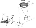
- FIG. 1 is a diagram showing a schematic configuration of a displacement measurement system according to the first embodiment.
- FIG. 2 is a block diagram showing a functional configuration of the displacement measurement system according to the first embodiment.
- FIG. 3 is a flowchart showing the operation of the displacement measurement system according to the first embodiment.
- FIG. 4 is a diagram for explaining feature point matching in the matching unit according to the first embodiment.
- FIG. 5 is a diagram for explaining a method of converting the actual size of the displacement according to the first embodiment.
- FIG. 6 is a flowchart showing the operation of the displacement measurement system according to the modified example of the first embodiment.
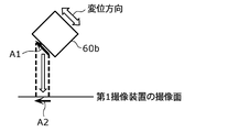
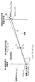
- FIG. 7A is a diagram for explaining displacement correction in consideration of the displacement direction according to the modified example of the first embodiment.
- FIG. 7B is a second diagram for explaining the displacement correction in consideration of the displacement direction according to the modified example of the first embodiment.
- FIG. 8 is a diagram for explaining a method of converting the actual size of the displacement according to the modified example of the first embodiment.
- FIG. 9 is a diagram showing a schematic configuration of the displacement measurement system according to the second embodiment.
- FIG. 10 is a block diagram showing a functional configuration of the displacement measurement system according to the second embodiment.
- FIG. 11 is a diagram showing an example of a marker attached to the first imaging device according to the second embodiment.
- FIG. 12 is a flowchart showing the operation of the displacement measurement system according to the second embodiment.
- an image including a specific portion whose length is known in the object to be displaced is imaged, and the number of pixels of the portion on the image corresponding to the specific portion is obtained.
- the specific portion be flat. That is, the method has restrictions on the shape of the specific portion of the object, and it is difficult to measure the actual size value of the displacement of the measurement point of the object having a complicated shape.
- the inventors have few restrictions on the installation of the camera and the distance measuring device, and there are few restrictions due to the shape of the object, that is, the correction parameter calculation for easily and accurately measuring the actual size value of the displacement.
- the correction parameter calculation method, etc. explained below.
- the correction parameter calculation method is a correction parameter calculation method for calculating a correction parameter for measuring an actual size displacement amount which is an actual size value of a displacement indicating the movement of an object using an image.
- a distance calculation step for calculating the first distance data from the first imaging device to the object based on the step, the position of the first imaging device, and the second distance data, and the first imaging device A parameter for calculating the correction parameter for converting the pixel displacement amount of the measurement point of the object based on two or more third image data captured at different timings into the actual size displacement amount using the first distance data. Includes calculation steps.
- the first distance from the first imaging device to the object can be calculated based on the estimated position of the first imaging device, so that the optical axis of the first imaging device can be calculated. It is not necessary to install the first imaging device and the second imaging device so that the optical axes of the second imaging device are parallel to each other. Further, according to the correction parameter calculation method, the correction parameter can be calculated based on the first distance, so that the pixel displacement amount is converted into the actual size displacement amount even if the length of the specific portion of the object is not known. The correction parameters for this can be calculated.
- the distance from the first imaging device to the object can be accurately acquired by estimating the first distance. Therefore, according to the correction parameter calculation method, by calculating the correction parameter using the first distance, it is possible to obtain a correction parameter capable of calculating a more accurate actual size displacement amount. For example, it is possible to acquire a correction parameter for calculating the actual size displacement amount with higher accuracy than when the second distance is used. Therefore, according to the correction parameter calculation method according to the present disclosure, the displacement amount is calculated using the correction parameter calculated by the correction parameter calculation method, so that the displacement measurement using an image is accurate and easy. The amount of displacement can be converted to the actual size value.
- the correction parameter calculation method is a correction parameter calculation method for calculating a correction parameter for measuring an actual size displacement amount which is an actual size value of a displacement indicating the movement of an object using an image.
- the first step based on the step of detecting the shape of the image pickup device, the estimation step of estimating the position of the first image pickup device based on the detection result, the position of the first image pickup device, and the second distance data. Pixels of measurement points of the object based on the distance calculation step for calculating the first distance data from the image pickup device to the object and two or more third image data captured by the first image pickup device at different timings.
- the correction parameter for converting the displacement amount into the actual size displacement amount includes a parameter calculation step of calculating the correction parameter using the first distance data.
- the position information of the first imaging device can be estimated using only the second image data and the distance data, so that the first imaging device is not affected by the position and number of feature points obtained from the image.
- Position information can be estimated. That is, the position information of the first imaging device can be easily estimated.
- the distance from the first imaging device to the object can be accurately acquired by estimating the first distance. Therefore, according to the correction parameter calculation method, by calculating the correction parameter using the first distance, it is possible to obtain a correction parameter capable of calculating a more accurate actual size displacement amount. For example, it is possible to acquire a correction parameter for calculating the actual size displacement amount with higher accuracy than when the second distance is used. Therefore, according to the correction parameter calculation method according to the present disclosure, the displacement amount is calculated using the correction parameter calculated by the correction parameter calculation method, so that the displacement measurement using an image is accurate and easy. The amount of displacement can be converted to the actual size value.
- the distance calculation step there are two or more measurement points for measuring the displacement in the object, and in the distance calculation step, two or more of the first distance data from each of the two or more measurement points to the first imaging device are obtained.
- the correction value corresponding to the measurement point is calculated as the correction parameter for each of the two or more measurement points based on the two or more first distance data.
- the correction value is calculated at each of the plurality of measurement points, so that the actual size displacement amount of each of the plurality of measurement points can be calculated accurately.
- a plurality of the first distance data from each of the plurality of surface points in the object including the two or more measurement points to the first imaging device are calculated, and the parameters are calculated.
- a correction value corresponding to the surface point is calculated for each of the plurality of surface points based on the plurality of first distance data, and a correction value map is used as the correction parameter based on the calculated correction value.
- the correction parameter calculation method when it is desired to measure the actual size displacement amount at a position other than the measurement point, the actual size displacement amount can be easily measured by using the correction value map. Therefore, the convenience of the correction parameter calculation method is improved.
- the third acquisition step of acquiring the displacement direction information indicating the displacement direction of the object is included, and in the parameter calculation step, the correction parameter is further calculated using the displacement direction information.
- the correction value is calculated using the displacement direction information. Since it can be calculated, the actual size value of the displacement can be measured more accurately.
- the first imaging device has a first camera
- the second imaging device has a second camera that captures the second image data and a depth sensor that measures the second distance data.
- the first camera has a higher resolution or a higher frame rate than the second camera.
- a monochrome camera can capture a higher-definition image than a color camera. Therefore, by measuring the displacement based on the monochrome image captured by the monochrome camera, the displacement can be measured with high accuracy. Further, since the depth sensor can be easily obtained, it is possible to provide a highly versatile correction parameter calculation method.
- the displacement amount calculation method includes a fourth acquisition step of acquiring the correction parameter calculated by using the above correction parameter calculation method, and a fifth acquisition of the two or more third image data.
- the acquisition step includes a conversion step of converting the pixel displacement amount in the two or more third image data into the actual size displacement amount based on the correction parameter.
- the actual size displacement amount can be measured using the correction parameter calculated by the above correction parameter calculation method, so that the actual size displacement amount of the object can be measured accurately and easily.
- the correction parameter calculation device is a correction parameter calculation device for calculating a correction parameter for measuring an actual size displacement amount which is an actual size value of a displacement indicating the movement of an object using an image.
- the first acquisition unit that acquires the first image data obtained by imaging the object from the first imaging device, and the second imaging device arranged at a position different from that of the first imaging device to the object.
- the second acquisition unit that acquires the second distance data and the second image data obtained by imaging the object from the second imaging device, the position of the object in the first image data, and the above.
- Position estimation that estimates the position of the first imaging device with respect to the second imaging device based on the matching unit that associates the position of the object in the second image data with the matching result and the second distance data.
- the distance calculation unit that calculates the first distance data from the first image pickup device to the object based on the unit, the position of the first image pickup device, and the second distance data, and the first image pickup device.
- the first distance from the first image pickup device to the object can be calculated based on the estimated position of the first image pickup device, so that the light of the first image pickup device can be calculated. It is not necessary to install the first imaging device and the second imaging device so that the axis and the optical axis of the second imaging device are parallel to each other. Further, according to the correction parameter calculation device, the correction parameter can be calculated based on the first distance, so that the pixel displacement amount is converted into the actual size displacement amount even if the length of the specific portion of the object is not known. The correction parameters for this can be calculated.
- the distance from the first imaging device to the object can be accurately acquired by estimating the first distance. Therefore, according to the correction parameter calculation device, by calculating the correction parameter using the first distance, it is possible to acquire the correction parameter capable of calculating the actual size displacement amount more accurately. For example, it is possible to acquire a correction parameter for calculating the actual size displacement amount with higher accuracy than when the second distance is used. Therefore, according to the above-mentioned correction parameter calculation device, the displacement amount is calculated using the correction parameter calculated by the correction parameter calculation device, so that the displacement can be accurately and easily displaced in the displacement measurement using the image. The amount can be converted to the actual size value.
- the correction parameter calculation device is a correction parameter calculation device for calculating a correction parameter for measuring an actual size displacement amount which is an actual size value of a displacement indicating the movement of an object using an image.
- the first acquisition unit that acquires the first image data obtained by imaging the object from the first imaging device, and the second imaging device arranged at a position different from that of the first imaging device to the object.
- the second acquisition unit that acquires the second distance data and the second image data obtained by imaging the object and the first imaging device from the second imaging device, and the second image data in the second image data.
- a measurement point of the object based on a distance calculation unit that calculates the first distance data from the first imaging device to the object and two or more third image data captured by the first imaging device at different timings. It is provided with a parameter calculation unit that calculates the correction parameter for converting the pixel displacement amount of the above into the actual size displacement amount by using the first distance data.
- correction parameter calculation device can estimate the position information of the first image pickup device using only the second image data and the distance data, the position information of the first image pickup device can be easily estimated. Can be done.
- the distance from the first imaging device to the object can be accurately acquired by estimating the first distance. Therefore, according to the correction parameter calculation device, by calculating the correction parameter using the first distance, it is possible to acquire the correction parameter capable of calculating the actual size displacement amount more accurately. For example, it is possible to acquire a correction parameter for calculating the actual size displacement amount with higher accuracy than when the second distance is used. Therefore, according to the above-mentioned correction parameter calculation device, the displacement amount is calculated using the correction parameter calculated by the correction parameter calculation device, so that the displacement can be accurately and easily displaced in the displacement measurement using the image. The amount can be converted to the actual size value.
- the displacement amount calculation device includes a third acquisition unit that acquires the correction parameter calculated by using the correction parameter calculation device, and a fourth acquisition unit that acquires two or more third image data. It includes an acquisition unit and a conversion unit that converts the pixel displacement amount in the two or more third image data into the actual size displacement amount based on the correction parameter.
- these general or specific aspects may be realized by a system, a method, an integrated circuit, a computer program, or a non-temporary recording medium such as a computer-readable CD-ROM, and the system, the method, the integrated. It may be realized by any combination of circuits, computer programs or recording media.
- the program may be stored in the recording medium in advance, or may be supplied to the recording medium via a wide area communication network including the Internet or the like.
- each figure is a schematic diagram and is not necessarily exactly illustrated. Further, in each figure, substantially the same configuration may be designated by the same reference numerals, and duplicate description may be omitted or simplified.
- the image is a still image but may be a moving image.
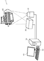
- FIG. 1 is a diagram showing a schematic configuration of a displacement measurement system 1 according to the first embodiment.
- FIG. 2 is a block diagram showing a functional configuration of the displacement measurement system 1 according to the first embodiment.
- the displacement measurement system 1 is an information processing system that measures the actual size value of the displacement of the object 60 by using two imaging devices arranged at different positions from each other. ..
- the first imaging device 10 and the second imaging device 20 image the object 60 from different viewpoints.
- the object 60 is an object for measuring displacement, for example, a device that is displaced (vibration, etc.) during operation of a motor or the like, but is not limited to this, and is displaced (for example, due to external stress such as an infrastructure structure). It may be a structure that is deformed).
- the infrastructure structure may be, for example, a bridge on which a vehicle such as an automobile or a railroad travels.
- the displacement in the present specification includes not only the vibration of the object 60 but also the deformation and the change of the position of the object 60. It can be said that the displacement indicates the movement of the object.
- the displacement measurement system 1 includes a first imaging device 10, a second imaging device 20, a displacement measuring device 30, an output device 40, and an input device 50.
- the first imaging device 10 captures an image for measuring the displacement of the object 60.
- the image captured by the first imaging device 10 is used to detect the amount of displacement (number of pixels) on the image with respect to the displacement of the object 60.
- the image captured by the first imaging device 10 is also described as the first image, and the amount of displacement on the image with respect to the displacement of the object 60 is also described as the amount of pixel displacement.
- the pixel displacement amount is an example of a physical quantity (for example, the number of pixels) on a pixel.
- the first image may be used to calculate a correction value described later.
- the first imaging device 10 is, for example, a monochrome camera.
- the first image is, for example, a monochrome image.
- the first imaging device 10 is not limited to a monochrome camera, and may be a color camera.
- the first imaging device 10 is, for example, a digital video camera or a digital still camera having an image sensor.
- the first imaging device 10 is an example of an imaging device.
- the monochrome camera or color camera included in the first imaging device 10 is an example of the first camera.
- the first camera has a higher resolution or a higher frame rate than the second camera described later.
- the first camera is, for example, a camera capable of capturing an image having a higher resolution than the second camera, or a camera capable of capturing an image at a high frame rate.
- the second imaging device 20 captures an image for measuring the actual size value of the displacement of the object 60.
- the second imaging device 20 has a configuration capable of acquiring an image obtained by capturing an image of the object 60 and a distance from the second imaging device 20 to the object 60.
- the image captured by the second imaging device 20 and the distance measured by the second imaging device 20 are used to estimate the position of the first imaging device 10.
- the image captured by the second imaging device 20 is also described as the second image
- the actual size value of the displacement of the object 60 is also described as the actual size displacement amount.
- the actual size displacement amount is an example of a physical quantity in real space (for example, a distance corresponding to the number of pixels).
- the distance from the second imaging device 20 to the object 60 is an example of the second distance.
- the second imaging device 20 has an imaging unit for capturing a second image and a distance measuring unit for measuring a distance.
- the image pickup unit is, for example, a color camera, but may be a monochrome camera.
- the imaging unit only needs to be able to acquire a shade image of the object 60.
- the distance measuring unit has, for example, a depth sensor.
- the depth sensor can measure the distance to one or more points of the object 60.
- the second imaging device 20 and the object 60 are based on the time until the laser beam hits the object 60 and bounces off the object 60. Acquire the distance (for example, the positional relationship).
- the depth sensor may be, for example, a laser rider.
- the distance measuring unit is not limited to having a depth sensor, and may have, for example, a TOF type sensor.
- the imaging unit and the distance measuring unit may be integrally configured or may be configured to be removable.
- the second imaging device 20 is an example of a measuring device.
- the monochrome camera or color camera included in the second imaging device 20 is an example of the second camera.
- the first imaging device 10 and the second imaging device 20 may image the same object 60 at different timings, for example.
- the first imaging device 10 and the second imaging device 20 may image the object 60 in synchronization with each other, for example.
- the predetermined value may be set based on an allowable value of displacement error or the like.
- the second imaging device 20 may perform imaging and measurement at least once after being installed.
- the imaging by the imaging unit of the second imaging device 20 and the measurement by the distance measuring unit may be performed at different timings, and the displacement of the object 60 may be performed. If is larger than a predetermined value, it is preferable to perform the operation synchronously.
- Each of the first imaging device 10 and the second imaging device 20 may be fixed so that the position does not move during imaging. Further, the second imaging device 20 may be arranged near the first imaging device 10. Each of the first imaging device 10 and the second imaging device 20 may be arranged at a position where an image including each of the measurement points of the object 60 can be acquired.
- the first image may be an image having a higher resolution than the second image, or may be an image captured under imaging conditions having a higher frame rate than the second image.
- the first image is a monochrome image and the second image is a color image, but the present invention is not limited to this.
- the displacement measuring device 30 calculates a correction value for converting the pixel displacement amount into the actual size displacement amount based on the image data and the distance data acquired from the first imaging device 10 and the second imaging device 20, and the calculated correction. It is an information processing device that outputs the actual size displacement amount of the object 60 by using the value.
- the displacement measuring device 30 may be, for example, a server device.
- the displacement measuring device 30 includes a correction parameter calculation unit 110, a displacement detection unit 120, and a displacement amount calculation unit 130.
- the correction parameter calculation unit 110 calculates a correction value for converting the pixel displacement amount into the actual size displacement amount based on the image data and the distance data acquired from the first image pickup device 10 and the second image pickup device 20.
- the correction parameter calculation unit 110 includes a first acquisition unit 111, a second acquisition unit 112, a matching unit 113, a position estimation unit 114, a distance calculation unit 115, and a correction value calculation unit 116.
- the first acquisition unit 111 acquires the first image data indicating the first image from the first image pickup device 10.
- the second acquisition unit 112 acquires the distance image data from the second image pickup device 20.
- the second acquisition unit 112 acquires, for example, the second image data and the distance data indicating the second image.
- the first acquisition unit 111 and the second acquisition unit 112 are communication interfaces (communication circuits) that are communicably connected to each of the first image pickup device 10 and the second image pickup device 20 via wireless communication or wired communication.
- the matching unit 113 associates the position of the object 60 in the first image data with the position of the object 60 in the second image data by matching the feature points of the first image data and the second image data.
- the matching unit 113 associates, for example, the positions (for example, pixel positions) of the object 60 in the first image data and the second image data.
- the matching unit 113 acquires correspondence information indicating the correspondence between the position of the object 60 in the first image data and the position of the object 60 in the second image data.
- any existing technique such as SIFT (Scale Invariant Feature Transfer: scale-invariant feature conversion) may be used.
- the position estimation unit 114 estimates the position of the first imaging device 10 based on the corresponding information, the distance data, and the internal parameters of the first imaging device 10. Specifically, the position estimation unit 114 estimates the position of the first image pickup device 10 in the coordinate system of the second image pickup device 20. It is assumed that the internal parameters of the first imaging device 10 are known. Further, the internal parameter includes at least one such as a parameter matrix (cameraMatrix) of 3 rows ⁇ 3 columns, a distortion coefficient (distCoeffs) of a lens, a focal length, and the like.
- the distance calculation unit 115 calculates the distance information indicating the distance from the first imaging device 10 to the object 60 based on the position information indicating the position of the first imaging device 10 and the distance data.
- the distance calculation unit 115 calculates, for example, the distance from the first imaging device 10 to each of one or more measurement points of the object 60.
- the distance calculation unit 115 may calculate, for example, the distance to a plurality of surface points including the measurement points for measuring the displacement of the object 60. Then, the distance calculation unit 115 may generate a distance map in which the distances from the first imaging device 10 to the object 60 are arranged.
- the number of measurement points of the object 60 is not particularly limited and may be 2 or more.
- the correction value calculation unit 116 converts the pixel displacement amount into the actual size displacement amount based on the position of the first image pickup device 10, the distance from the first image pickup device 10 to the object 60, and the internal parameters of the first image pickup device 10. Calculate the correction value for conversion. The calculation of the correction value by the correction value calculation unit 116 will be described later. Further, the correction value calculation unit 116 may calculate the correction value at each of the plurality of surface points and generate a correction value map in which the calculated correction values are arranged. The correction value and the correction value map are examples of correction parameters. The correction value calculation unit 116 is an example of the parameter calculation unit.
- the correction parameter calculation unit 110 has described an example built in the displacement measuring device 30, but the present invention is not limited to this.
- the correction parameter calculation unit 110 may be realized as a single device. In this case, the correction parameter calculation unit 110 functions as a correction parameter calculation device.
- the displacement measuring device 30 is an example of a displacement amount calculating device.
- the displacement detection unit 120 detects the amount of pixel displacement (number of pixels) on the image corresponding to the displacement of the object 60 based on two or more first image data images captured by the first imaging device 10.
- the displacement detection unit 120 detects, for example, the amount of pixel displacement for each measurement point.
- the displacement amount calculation unit 130 calculates the actual size displacement amount of the object 60 by converting the pixel displacement amount into the actual size displacement amount based on the pixel displacement amount and the correction information indicating the correction parameter.
- the displacement amount calculation unit 130 is, for example, based on the correction value of each of the plurality of measurement points of the object 60 and the pixel displacement amount of each of the plurality of measurement points, and the actual size displacement of each of the plurality of measurement points. Calculate the amount.
- the output device 40 is a device that acquires presentation information including the actual size displacement amount from the displacement measuring device 30 and outputs the acquired presentation information.
- the output device 40 is, for example, a display device that displays the presented information as an image.
- the output device 40 is, for example, a liquid crystal display or the like. The image output by the output device 40 is visually recognized by the worker.
- the output device 40 may be a stationary device or a device possessed by a mobile terminal possessed by a worker.
- the mobile terminal is not particularly limited as long as it has an output device 40 and can communicate with the displacement measuring device 30, and may be, for example, a smartphone or a tablet.
- the worker can know the actual size displacement amount by checking the output device 40 of the mobile terminal around the object 60.
- the worker is an example of a user.
- the displacement measurement system 1 may include a device that outputs sound together with the display device or in place of the display device as the output device 40. Further, the displacement measurement system 1 may include a device for displaying presentation information on an object (for example, a screen) such as a projector as an output device 40. When the displacement measuring device 30 is located at a remote location, the displacement measuring device 30 and the output device 40 may be connected via a network.
- the input device 50 is a user interface that receives predetermined information in displacement measurement from a worker.
- the input device 50 may, for example, receive information for calculating a correction value from an operator, may receive information regarding the displacement direction of the object 60, or may receive information regarding the approximate position of the first imaging device 10. May be accepted. Further, the input device 50 may accept input of predetermined information by voice.
- the approximate position is an estimated value of the installation position of the first imaging device 10.
- the input device 50 is realized by a hardware key (hardware button), a slide switch, a touch panel, or the like.
- the input device 50 may be a stationary device or a device possessed by a mobile terminal possessed by a worker.
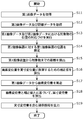
- FIG. 3 is a flowchart showing the operation of the displacement measurement system 1 according to the first embodiment.
- FIG. 3 is a flowchart showing the operation of the displacement measuring device 30.
- steps S11 to S16 shown in FIG. 3 show the operation of the correction parameter calculation unit 110.
- FIG. 4 is a diagram for explaining feature point matching in the matching unit 113 according to the first embodiment. Note that FIG. 4 shows an example in which the object 60a is furniture.
- a QR (Quick Response) code registered trademark
- Each of the QR codes may be provided corresponding to the measurement point of the object 60a.
- the first acquisition unit 111 acquires the first image data indicating the first image from the first image pickup apparatus 10 (S11).
- the first acquisition unit 111 acquires, for example, the first image data I1 as shown in FIG. 4A.
- the positions (x, y) indicated by “ ⁇ ” indicate, for example, the pixel positions of the feature points on the first image data I1.
- the positions of the five feature points are illustrated.
- the QR code registered trademark
- the first acquisition unit 111 may acquire at least one first image data in step S11 in order to calculate the correction value. Further, in order to measure the displacement, the first acquisition unit 111 may acquire two or more first image data captured at different timings in step S11.
- the first acquisition unit 111 When a plurality of first image data are acquired, the first acquisition unit 111 outputs at least one first image data to the matching unit 113, and outputs two or more first image data to the displacement detection unit 120. To do.
- the first acquisition unit 111 may output different first image data to the matching unit 113 and the displacement detection unit 120, or may output at least a part of the same first image data.
- the two or more first image data output to the displacement detection unit 120 are image data captured at different timings, and are an example of the third image data.
- step S11 is an example of the first acquisition step. Further, step S11 may be an example of a fifth acquisition step in the displacement amount calculation method described later. Further, the first acquisition unit 111 may function as a fourth acquisition unit for acquiring two or more third image data.
- the second acquisition unit 112 acquires the second image data indicating the second image and the distance data indicating the distance from the second imaging device 20 (S12).
- the second acquisition unit 112 acquires, for example, the second image data and the distance image data I2 indicating the distance data as shown in FIG. 4B.
- the distance image data I2 includes coordinates (X, Y, Z) indicating the position of the object 60 with respect to the second imaging device 20 (for example, indicated by “ ⁇ ” in (b) of FIG. 4) and a color at the position. Includes pixel values (R, G, B) indicating.
- the coordinates (X, Y, Z) are coordinates based on the position of the second imaging device 20 (for example, the coordinates (0, 0, 0)).
- the distance data is an example of the second distance data.
- the distance image data I2 does not have to include color information.
- the distance image data I2 may be an image capable of feature point matching with the first image data I1 and include coordinates (X, Y, Z) indicating the position of the object 60 with respect to the second imaging device 20. Just do it.
- the distance image data I2 may be, for example, an image showing the shading of the object 60 and may be data including coordinates (X, Y, Z) indicating the position of the object 60 with respect to the second imaging device 20. ..
- the distance image data I2 may include a black-and-white image or a shade image obtained by capturing the object 60.
- the second acquisition unit 112 outputs the distance image data I2 to the matching unit 113 and the position estimation unit 114.
- the second image data is data including pixel values (R, G, B) indicating colors, and the distance data is coordinates (X, Y, Z) indicating the position of the object 60 with respect to the second imaging device 20. ) Is included in the data.
- step S12 is an example of the second acquisition step.
- the matching unit 113 executes the association of the positions of the objects 60 in the second image data of the first image data I1 and the distance image data I2 (S13).
- first image data I1 and the distance image data I2 shown in FIG. 4 for example, five feature point matching candidates (for example, “ ⁇ ” in (a) and (b) of FIG. 4) are extracted.
- the positions of the first image data I1 and the distance image data I2 are associated with each other.
- the matching unit 113 associates the pixel position (x, y) in the first image data I1 with the coordinates (X, Y, Z) in the distance image data I2.
- the matching unit 113 makes a correspondence by, for example, specifying at which position on the distance image data I2 the portion of the object 60 at the pixel position (x, y) on the first image data I1 is located.
- the matching unit 113 for example, from the correspondence between the pixel position (x, y) in the first image data I1 and the pixel position (x1, y1) in the second image data, the pixel position in the first image data I1.
- (X, y) is associated with the coordinates (X, Y, Z) corresponding to the pixel position (x, y) in the distance data.
- the matching unit 113 associates the distance data corresponding to the pixel position with the pixel position (x, y) on the first image data I1.
- the matching unit 113 determines, for example, five sets of feature points, but the set of feature points is not limited to five sets, and is appropriately determined depending on the method of acquiring the correspondence relationship and the like. For example, the matching unit 113 may determine four sets of feature points or six sets.
- the method of calculating the correspondence and the number of feature points are examples, and are not limited to the above. In the following, the number of sets of feature points will be described as n sets.
- the matching unit 113 outputs the correspondence information indicating the positional correspondence between the first image data I1 and the second image data to the position estimation unit 114.
- the matching unit 113 outputs, for example, correspondence information indicating the five sets of feature points determined above. Note that step S13 is an example of a matching step.
- the position estimation unit 114 estimates the position of the first image pickup device 10 with respect to the second image pickup device 20 based on the corresponding information, the distance data, and the internal parameters of the first image pickup device 10 (S14).
- the position estimation unit 114 knows the correspondence between the first image data I1 and the distance image data I2 at n sets of specific points, the position estimation unit 114 solves the PnP problem (Perspective-n-Point Problem) of the second image pickup apparatus 20.
- the position of the first imaging device 10 in the coordinate system can be estimated. It is assumed that the internal parameters of the first imaging device 10 are known.
- the position estimation unit 114 calculates R (rotation) and T (position) using each of the set of feature points whose reprojection error is equal to or less than the reference value, so that the position estimation unit 114 has a second position with respect to the second image pickup apparatus 20. 1 Estimate the position and orientation of the imaging device 10.
- the position estimation unit 114 calculates, for example, R (rotation matrix) and T (translation vector) that minimize the reprojection error.
- R (rotation matrix) is an external parameter indicating the posture of the first imaging device 10.
- T (translation vector) is an external parameter indicating the position of the first imaging device 10.
- the position estimation unit 114 may at least estimate the position.
- the matching unit 113 and the position estimation unit 114 execute a process of estimating the position of the first imaging device 10 by, for example, robust estimation that reduces the influence of outliers in order to eliminate erroneous association of feature points. May be good.
- the matching unit 113 and the position estimation unit 114 may estimate the position of the first imaging device 10 by, for example, RANSAC (RANdom Sample Consensus) estimation, median estimation, M estimation, etc., which are examples of robust estimation.
- RANSAC estimation may be, for example, an estimation method based on the reprojection error.
- the reprojection error is the second position (xi, yi) on the second image data obtained by projecting the first position (Xi, Yi, Zi) on the distance data obtained by using the function that converts the two coordinate systems. , It is represented by a squared error with the third position (xi0, yi0) on the first image data corresponding to the second position.
- the function that converts the two coordinate systems is, for example, the projectPoints function.
- the matching unit 113 randomly selects n sets of feature points and calculates the position of the first imaging device 10. Then, the matching unit 113 calculates the number of sets of specific points whose reprojection error is equal to or less than the reference value among the n sets. The matching unit 113 repeats the above processing for all the feature points in the image, and determines n sets of feature points that maximize the number of sets of specific points whose reprojection error is equal to or less than the reference value. Then, the position estimation unit 114 may estimate the position of the first imaging device 10 by using, for example, the n sets of feature points. The n sets may be, for example, 6 sets. That is, the position estimation unit 114 may estimate the position of the first imaging device 10 by solving the P6P problem.
- the matching unit 113 and the position estimation unit 114 acquire the correspondence between the feature points of the object 60 in the first image data I1 and the second image data, and the first imaging device uses the correspondence. Ten positions are estimated. That is, the displacement measuring device 30 according to the first embodiment can estimate the position of the first imaging device 10 even if the installation position and the installation posture of the first imaging device 10 and the second imaging device 20 are different.
- the position estimation unit 114 outputs the position information indicating the estimated position of the first imaging device 10 to the distance calculation unit 115.
- step S14 is an example of an estimation step.
- the distance calculation unit 115 calculates the distance from the first imaging device 10 to the object 60 based on the position information and the distance data (S15).
- the distance calculation unit 115 starts from the first imaging device 10 based on the position (coordinates) of the first imaging device 10 included in the position information and the coordinates (X, Y, Z) of the object 60 based on the distance data. Calculate the distance to the object 60. It can be said that the distance calculation unit 115 converts the distance to the object 60 measured by the distance measurement unit of the second image pickup device 20 into the distance to the object 60 as seen from the first image pickup device 10. As a result, the position of the object 60 when viewed from the first imaging device 10 is acquired.
- the distance to each measurement point of the object 60 when viewed from the first imaging device 10 is acquired.
- the data including the distance calculated by the distance calculation unit 115 (the distance from the first imaging device 10 to the object 60) is an example of the first distance data.
- the distance calculated by the distance calculation unit 115 is an example of the first distance.
- the distance calculation unit 115 outputs distance information indicating the distance between the first imaging device 10 and the object 60 to the correction value calculation unit 116.
- step S15 is an example of a distance calculation step.
- the correction value calculation unit 116 calculates a correction value for converting the pixel displacement amount into the actual size displacement amount based on the position and distance information of the first image pickup device 10 and the internal parameters of the first image pickup device 10. S16).
- the correction value calculation unit 116 calculates a correction value for each of a plurality of measurement points of the object 60, for example.
- the correction value includes, for example, information indicating an actual size value corresponding to one pixel at the measurement point.
- Step S16 is an example of the parameter calculation step. Further, step S16 may be an example of the fourth acquisition step.
- FIG. 5 is a diagram for explaining a method of converting the actual size of the displacement according to the first embodiment.
- FIG. 5 shows an example in which the object 60 is displaced in a direction parallel to the imaging surface (projection surface) of the first imaging device 10.
- the optical center O shown in FIG. 5 indicates the center of the lens 11 of the first image pickup apparatus 10, and the position P1 (x, y) is the position M1 (X, Y, Z) of the measurement point at the first time point of the object 60.
- the displacements ( ⁇ x1, ⁇ y1) on the image are the positions P2 and the positions on the imaging surface corresponding to the position M2 of the measurement point at the second time point different from the first time point. The difference from P1 is shown.
- the displacement ( ⁇ x1, ⁇ y1) is the number of pixels on the image.
- the first time point is, for example, an initial time point when the object 60 is not displaced.
- the distance L2 between the optical center O and the position M1 is determined by the similarity between the triangle ⁇ OP1P2 and the triangle ⁇ OM1M2.
- the correction value calculation unit 116 calculates the correction value based on the above (Equation 2).
- the correction value for calculating the displacement Dx1 is a correction value based on (Equation 2), and is L2 / L1.
- the correction value for calculating the displacement Dy1 is also a correction value based on (Equation 2) and is L2 / L1.
- the image center (Cx, Cy) and the focal length f are acquired as internal parameters of the first image pickup apparatus 10.
- the correction value calculation unit 116 may calculate the internal parameters of the first imaging device 10 using the chart image.
- the correction value calculation unit 116 outputs correction information indicating the calculated correction value to the displacement amount calculation unit 130.
- the displacement amount calculation unit 130 acquires correction information from the correction value calculation unit 116.
- the displacement amount calculation unit 130 functions as a third acquisition unit for acquiring correction parameters.
- the displacement detection unit 120 calculates the amount of pixel displacement of the displacement of the object 60 on the first image data I1 from the first image data I1 (S17).
- the displacement detection unit 120 calculates, for example, the pixel displacement amount from the displacement of the object 60 projected on the imaging surface of the first imaging device 10.
- the displacement detection unit 120 calculates, for example, how many pixels on the image the displacement at the measurement point is for each of a plurality of measurement points of the object 60.
- the displacement detection unit 120 outputs the calculated pixel displacement amount to the displacement amount calculation unit 130.
- the displacement amount calculation unit 130 calculates the actual size displacement amount based on the pixel displacement amount and the correction value (S18).
- the displacement amount calculation unit 130 calculates the actual size displacement amount at the measurement point by calculating the pixel displacement amount at the measurement point and the correction value at the measurement point for each of the plurality of measurement points of the object 60. In this way, the displacement amount calculation unit 130 functions as a conversion unit that converts the pixel displacement amount in the two or more third image data into the actual size displacement amount based on the correction information.
- the displacement amount calculation unit 130 outputs the presentation information including the calculated actual size displacement amount to the output device 40 (S19). Then, the output device 40 displays the presentation information acquired from the displacement amount calculation unit 130 as an image. Note that step S19 is an example of a conversion step.
- step S11 to step S16 shown in FIG. 3 may be performed every time the process of calculating the actual size displacement amount of the object 60 is executed, or the first imaging device 10 and the second imaging device 20 may be performed. It may be done every time at least one of the installation position, orientation, and camera parameters (including internal parameters) of the above is changed. Further, the correction value calculation unit 116 may store the calculated correction value in a storage unit (not shown). Then, when calculating the actual size displacement amount of the object 60, the correction value calculation unit 116 may read the correction value from the storage unit and output the read correction value to the displacement amount calculation unit 130. That is, the correction value calculation unit 116 may use the correction value calculated in the past as the correction value for calculating the current actual size displacement amount. As a result, the processing amount of the correction parameter calculation unit 110 can be reduced.
- the above steps S11 to S16 are processes executed in the correction parameter calculation method for calculating the correction parameter. Further, the steps S17 to S19 described above are processes executed in the displacement amount calculation method for calculating the actual size displacement amount.
- the displacement amount calculation method may include the processes of steps S11 to S16.
- the displacement measurement system 1 includes a first image pickup device 10 and a second image pickup device 20 arranged at different positions from each other, and a displacement measurement device 30 having a correction parameter calculation unit 110. Be prepared.
- the correction parameter calculation unit 110 estimates the position of the first image pickup device 10 based on the first image data I1 acquired from the first image pickup device 10 and the distance image data I2 acquired from the second image pickup device 20.
- the displacement measuring device 30 since the correction parameter calculation unit 110 estimates the position of the first imaging device 10, the displacement is accurately displaced even if the positions and orientations of the first imaging device 10 and the second imaging device 20 are initially different. The actual size value of can be calculated.
- the displacement measurement system 1 there are few restrictions on the positions and orientations of the first imaging device 10 and the second imaging device 20, so that the positions and orientations of the first imaging device 10 and the second imaging device 20 can be finely adjusted. No need to adjust. Therefore, the installation time at the measurement site can be shortened. Further, since the number of image pickup devices to be installed is smaller than that in the case of measuring the actual size displacement amount of the object 60 by the multi-viewpoint method, it is possible to easily install and collect the image pickup devices at the measurement site.
- the correction parameter calculation unit 110 calculates a correction value for converting the pixel displacement amount into the actual size displacement amount, for example, using the estimated position of the first imaging device 10. As a result, the correction parameter calculation unit 110 can measure the actual size displacement amount of the object 60 even if the object 60 to which the scale marker is not attached or the object 60 whose actual size length of the specific part is unknown. Is.
- the correction parameter calculation unit 110 calculates a correction value for each of a plurality of measurement points of the object 60, for example. As a result, the operator can select the measurement points without worrying about the difference in distance between the first imaging device 10 and each of the plurality of measurement points. That is, according to the correction parameter calculation unit 110, the degree of freedom in selecting the measurement point is increased.
- the displacement measuring device 30 measures the actual size displacement amount of the displacement of the object 60 by using two or more first image data images captured by the first imaging device 10. As a result, the displacement measuring device 30 can measure the actual size displacement amount even if the displacement of the object 60 is based on vibration having a period that cannot be measured by using a laser displacement meter or the like.
- the physical quantity in the real space is not particularly limited as long as it is a physical quantity that can be obtained from the image data, and may be, for example, a length or an area. Further, the physical quantity in the real space may be the speed of displacement or the like based on the actual size displacement amount of the plurality of frames.
- the parameter calculation step (corresponding to S16)
- the physical quantity on the pixel of the measurement point of the object 60 based on the two or more third image data imaged at different timings by the first imaging device 10 is measured in real space.
- the correction parameter for converting to the physical quantity in is calculated using the first distance data.
- the displacement measuring device 30 described in the present embodiment is a physical quantity measuring device.
- the correction parameter calculation method for calculating the correction parameter for calculating such a physical quantity in the real space is shown below.
- it is a correction parameter calculation method for calculating a correction parameter for measuring an actual size physical quantity which is an actual size value of the physical quantity of the object 60 in the real space using an image, and is obtained by imaging the object 60.
- the second acquisition step (corresponding to S12) for acquiring the distance data and the second image data obtained by imaging the object 60 from the second imaging device 20, and the position of the object 60 in the first image data I1.
- the first imaging device 10 with respect to the second imaging device 20 based on the matching step (corresponding to S13) for associating the position of the object 60 in the second image data with the second image data, and the matching result and the second distance data.
- Distance calculation step (S15) for calculating the distance data from the first imaging device 10 to the object 60 based on the estimation step (S14) for estimating the position of the first imaging device 10 and the position of the first imaging device 10 and the second distance data.
- the correction value (an example of the correction parameter) for converting the physical quantity on the pixel of the measurement point of the object 60 based on the third image data captured by the first imaging apparatus 10 into the physical quantity in the real space.
- a parameter calculation step (corresponding to S16) calculated using the first distance data may be included.
- the correction parameter calculation device 110 may be realized as a correction parameter calculation device 110 for calculating a correction parameter for measuring an actual size physical quantity which is an actual size value of the physical quantity of the object 60 in the real space using an image.
- the correction parameter calculation device 110 is arranged at a position different from that of the first acquisition unit 111 that acquires the first image data obtained by imaging the object 60 from the first image pickup device 10 and the first image pickup device 10.
- the second acquisition unit 112 and the second acquisition unit 112 that acquire the second distance data from the second imaging device 20 to the object 60 and the second image data obtained by imaging the object 60 from the second imaging device 20.
- the second imaging device 20 is based on the matching matching unit 113 that associates the position of the object 60 in the first image data with the position of the object 60 in the second image data, and the matching result and the second distance data.
- the position estimation unit 114 that estimates the position of the first image pickup device 10 with respect to the position, the position of the first image pickup device 10, and the second distance data, the first distance data from the first image pickup device 10 to the object 60 is obtained.
- the distance calculation unit 115 to calculate, and the correction parameter for converting the physical quantity on the pixel of the measurement point of the object 60 based on the third image data captured by the first imaging device 10 into the physical quantity in the real space.
- a correction value calculation unit 116 calculated using the first distance data may be provided.
- the displacement measurement system 1 according to this modification accurately calculates the actual size displacement amount even when the displacement direction of the object 60 is different from the horizontal direction with the imaging surface (projection surface) of the first imaging device 10. It is characterized in that it can be used.
- FIG. 6 is a flowchart showing the operation of the displacement measurement system 1 according to this modification.
- the correction value calculation unit 116 acquires the displacement direction information of the object 60 (S21).
- the correction value calculation unit 116 may acquire displacement direction information via, for example, the input device 50.
- the displacement direction information may be, for example, information indicating the displacement direction based on the drive direction of the drive unit of the motor when the object 60 is a motor.
- the displacement direction information may be information indicating the predicted displacement direction, for example, when the displacement direction of the object 60 can be predicted by design.
- the displacement direction information may be information indicating, for example, the direction in which the object 60 receives stress (for example, the vertical direction) when the object 60 is a bridge or the like and receives stress from a vehicle or the like.
- the displacement direction information may be, for example, information indicating the direction of the first imaging device 10 with respect to the imaging surface. Further, the displacement direction indicated by the displacement direction information is not limited to one, and may be two or more. Step S21 is an example of the third acquisition step.
- the displacement direction information is not limited to being acquired via the input device 50.
- the displacement direction information may be determined based on, for example, two or more distance image data I2 (for example, second image data).
- the second acquisition unit 112 acquires two or more distance image data I2 imaged at different timings from the second imaging device 20, and obtains at least two or more distance image data I2 as the correction value calculation unit 116. Output to (not shown).
- the correction value calculation unit 116 acquires the displacement direction information by specifying the displacement direction based on the positions (X, Y, Z) of the predetermined measurement points included in each of the two or more distance image data I2. Good.
- the orientation of the surface of the displacement measurement point on the object 60 is acquired from the distance image data I2, and the displacement direction is defined with reference to the orientation of this surface (normal direction of the surface, direction parallel to the surface, etc.). May be good.
- the displacement direction information may be acquired based on the first image data I1.
- the object 60 may have a QR code (registered trademark) attached to it, for example, as shown in FIG. 4 (a).
- the QR code registered trademark
- the correction value calculation unit 116 may acquire the displacement direction of the object 60 based on the QR code (registered trademark) included in the first image data I1.
- the displacement direction may be, for example, a direction based on the surface of the object 60 to which the QR code (registered trademark) is attached.
- the QR code (registered trademark) is not limited to the object 60.
- an AR marker may be attached to the object 60.
- the correction value calculation unit 116 may acquire displacement direction information, which is information associated with the AR marker, based on the AR marker included in the first image data I1, for example.
- the displacement direction information may be superimposed and displayed on the first image data I1, for example.
- the correction value calculation unit 116 converts the pixel displacement amount into the actual size displacement amount based on the position and distance information of the first imaging device 10, the internal parameters of the first imaging device 10, and the displacement direction information.
- the correction value is calculated (S22). That is, the correction value calculation unit 116 calculates the correction value using the displacement direction information in addition to the first embodiment. Note that step S22 is an example of a parameter calculation step.
- FIG. 7A is a diagram for explaining displacement correction in consideration of the displacement direction according to this modification.
- FIG. 7B is a second diagram for explaining the displacement correction in consideration of the displacement direction according to the present modification.
- 7A and 7B are bird's-eye views of the object 60b as viewed from above. The shape of the object 60b is square for convenience.
- the imaging surface is not parallel to the imaging surface.
- the displacement direction is the direction connecting the upper left and the lower right on the paper surface.
- the displacement A2 is a component in the direction parallel to the imaging surface in the displacement A1.
- the displacement direction is the direction connecting the lower left and the upper right on the paper surface.
- the displacement of the measurement point of the object 60b is B1
- the displacement of the measurement point of the object 60b projected on the imaging surface is B2.
- the displacement B2 is a component in the direction parallel to the imaging surface in the displacement B1.
- the displacements A1 and B1 are actual size displacement amounts, for example, actual size values.
- the displacements A2 and B2 are pixel displacement amounts, for example, the number of pixels.
- displacements A1 and B1 having different actual displacement directions may be detected as displacements in the same direction on the imaging surface. With this, the displacement in the direction horizontal to the imaging surface can be measured, but the displacement in the direction perpendicular to the imaging surface cannot be measured.
- the correction value calculation unit 116 acquires the displacement direction information of the object 60 in step S21, and uses the displacement direction information in step S22 to obtain the first image data.
- a correction value for converting the pixel displacement amount of the object 60 on I1 into the actual size displacement amount is calculated.
- the correction value here includes an actual size value corresponding to one pixel and information indicating a displacement direction.
- the correction value may include, for example, information indicating an actual size value (Xa, Yb, Zc) corresponding to one pixel.
- the actual size value Xa indicates the actual size value of the displacement in the X-axis direction in the three-dimensional Cartesian coordinate system in the real space when the image is displaced by one pixel on the imaging surface.
- the actual size value Xb indicates the actual size value of the displacement in the Y-axis direction in the three-dimensional Cartesian coordinate system in the real space when the image is displaced by one pixel on the imaging surface.
- Xc indicates the actual size value of the displacement in the Z-axis direction in the three-dimensional Cartesian coordinate system in the real space when the image is displaced by one pixel on the imaging surface.
- the actual size values (Xa, Yb, Zc) are examples of correction parameters. The method of calculating the correction value is not limited to the above.
- FIG. 8 is a diagram for explaining a method of converting the actual size of the displacement according to the present modification.
- the position P1 on the imaging surface corresponding to the position M1 (X, Y, Z) of the measurement point at the first time point of the object 60 is (x, y)
- the distance L1 to P1 can be calculated by (Equation 1).
- the first time point is, for example, an initial time point when the object 60 is not displaced.
- the difference (displacement) between the position P3 and the position P1 on the imaging surface corresponding to the position M3 of the measurement point at the second time point different from the first time point is ( ⁇ x2, ⁇ y2)
- the first correction value is It can be calculated by (Equation 2).
- the first correction value here is a value capable of calculating the actual size displacement amount of the displacement in the direction parallel to the image pickup surface of the first image pickup apparatus 10.
- the first correction value is, for example, a value at which the displacement (Dx2, Dy2) of the actual size displacements (Dx2, Dy2, Dz2) can be calculated from the displacement ( ⁇ x2, ⁇ y2) on the image.
- the correction value calculation unit 116 converts the first correction value into a second correction value which is three-dimensional information based on the calculated first correction value and the displacement direction information.
- the correction value calculation unit 116 calculates a second correction value for converting the pixel displacement amount, which is two-dimensional information indicating the displacement on the imaging surface, into the actual size displacement amount, which is three-dimensional information.
- the correction value calculation unit 116 may calculate the second correction value based on the first correction value and the angle formed by the image pickup surface and the displacement direction of the first image pickup apparatus 10.
- the second correction value is, for example, a value capable of calculating the actual size displacement (Dx2, Dy2, Dz2) from the displacement ( ⁇ x2, ⁇ y2) on the image.
- the method by which the correction value calculation unit 116 calculates the second correction value is not limited to the above.
- the correction parameter calculation unit 110 of the displacement measurement system 1 further converts the pixel displacement amount into the actual size displacement amount by using the displacement direction information indicating the displacement direction of the object 60. Calculate the correction value of.
- the displacement measurement system 1 uses the displacement direction information to correct the value when the object 60 is displaced in the direction intersecting the imaging surface of the first imaging device 10 when the object 60 is viewed from above. Can be calculated, so that the actual size value of the displacement can be measured accurately.
- FIG. 9 is a diagram showing a schematic configuration of the displacement measurement system 1a according to the second embodiment.
- FIG. 10 is a block diagram showing a functional configuration of the displacement measurement system 1a according to the second embodiment.
- the second acquisition unit 112 mainly acquires the second image data and the distance data including the first imaging device 10 from the second imaging device 20, and the position estimation unit 114. Is different from the displacement measuring device 30 according to the first embodiment in that the position information of the first imaging device 10 is estimated using only the second image data and the distance data.
- the differences from the first embodiment will be mainly described, and the same components as those in the first embodiment will be designated by the same reference numerals, and the description may be omitted or simplified.
- the displacement measurement system 1a is an information processing system that measures the actual size value of the displacement of the object 60 by using two imaging devices arranged at different positions from each other. ..
- the first imaging device 10 and the second imaging device 20 image the object 60 from different viewpoints.
- the displacement measurement system 1a includes a first image pickup device 10, a second image pickup device 20, a displacement measurement device 30a, an output device 40, and an input device 50.
- the second image pickup device 20 captures an image including the first image pickup device 10 and the object 60.
- the second imaging device 20 may capture an image including the first imaging device 10 to the extent that the shape of the first imaging device 10 can be detected, or a marker is added to the housing of the first imaging device 10. If so, the image may be taken so that the marker is captured.
- the second imaging device 20 may image at a position or posture in which the first imaging device 10 and the object 60 do not overlap.
- the second imaging device 20 may be arranged, for example, behind the first imaging device 10.
- the displacement measuring device 30a is different from the displacement measuring device 30 of the first embodiment in that it does not have the matching unit 113.
- the first acquisition unit 111 acquires the first image data showing the first image including the object 60 from the first image pickup apparatus 10. Then, the first acquisition unit 111 outputs the acquired first image data to the displacement detection unit 120.
- the second acquisition unit 112 acquires the second image data and the distance data indicating the second image including the first image pickup device 10 and the object 60 from the second image pickup device 20.
- the position estimation unit 114 detects the first imaging device 10 from the distance data or the second image data. Since at least one of the appearance, size, and shape of the first image pickup device 10 is known in advance, the position estimation unit 114 may detect the first image pickup device 10 by two-dimensional or three-dimensional pattern matching. Further, the position estimation unit 114 detects the first imaging device 10 by the housing or lens of the first imaging device 10 or a marker attached to the housing of the first imaging device 10 as shown in FIG. May be good.
- FIG. 11 is a diagram showing an example of a marker 200 attached to the first imaging device 10 according to the second embodiment.
- FIG. 11A shows a state in which the marker 200 is attached to the upper surface of the first imaging device 10.
- FIG. 11B shows a state in which the marker 200 is attached to the side surface of the first imaging device 10. At least one marker is attached to the first imaging device 10.
- the position estimation unit 114 determines the three-dimensional position coordinates of the optical center based on the detected position of the first imaging device 10.
- the optical center position of the first image pickup apparatus 10 with respect to the housing or the like can be determined from the design values for the combination of the second camera and the lens, or can be obtained in advance by optical calibration.
- the position estimation unit 114 outputs the position information including the position coordinates of the first imaging device 10 when the obtained optical center is used as a reference (origin) to the distance calculation unit 115.
- the other configurations and operations included in the displacement measurement system 1a are the same as those in the first embodiment.
- the position estimation unit 114 estimates the position information of the first imaging device 10 using only the second image data and the distance data, it is not affected by the position or number of the feature points obtained from the image. In addition, there is an advantage that the position information of the first image pickup apparatus 10 can be estimated.
- FIG. 12 is a flowchart showing the operation of the displacement measurement system 1a according to the second embodiment. Specifically, FIG. 12 is a flowchart showing the operation of the displacement measuring device 30a.
- the first acquisition unit 111 acquires the first image data indicating the first image from the first image pickup apparatus 10 (S11).
- the first acquisition unit 111 acquires, for example, the first image data I1 as shown in FIG. 4A.
- Step S11 is an example of the first acquisition step.
- the second acquisition unit 112 acquires the second image data indicating the second image and the distance data indicating the distance from the second imaging device 20 (S31).
- the second acquisition unit 112 acquires the second image data including both the object 60 and the first image pickup device 10 and the distance data indicating the distance from the second image pickup device 20.
- the second acquisition unit 112 outputs the acquired second image data and distance data to the position estimation unit 114.
- Step S31 is an example of the second acquisition step.
- the position estimation unit 114 detects the first imaging device 10 from the distance data or the second image data.
- the position estimation unit 114 detects, for example, the first image pickup apparatus 10 in the second image data from the distance data or the second image data (S32).
- the position estimation unit 114 detects the shape of the first imaging device 10 in the second image data by, for example, the above method.
- the position estimation unit 114 estimates the three-dimensional position coordinates of the optical center based on the detected position of the first imaging device 10. It can be said that the position estimation unit 114 estimates the position of the first image pickup device 10 with respect to the second image pickup device 20 based on the detected position of the first image pickup device 10 (S33). In other words, the position estimation unit 114 estimates the position of the first imaging device 10 without using the corresponding information of the two images.
- the position estimation unit 114 outputs the position information including the position coordinates of the first imaging device 10 with the obtained optical center as a reference (origin) to the distance calculation unit 115.
- the position information also includes the distance data acquired by the second acquisition unit 112.
- step S15 Since the processing after step S15 is the same as that of the first embodiment, the description thereof will be omitted.
- the position estimation unit 114 estimates the position information of the first image pickup device 10 using the second image data including the first image pickup device 10 and the distance data, two images.
- the position information of the first imaging device 10 can be estimated without being affected by the position or number of the feature points.
- the physical quantity in the real space is not particularly limited as long as it is a physical quantity that can be obtained from the image data, and may be, for example, a length or an area. Further, the physical quantity in the real space may be the speed of displacement or the like based on the actual size displacement amount of the plurality of frames.
- the parameter calculation step (corresponding to S16)
- the physical quantity on the pixel of the measurement point of the object 60 based on the two or more third image data imaged at different timings by the first imaging device 10 is measured in real space.
- the correction parameter for converting to the physical quantity in is calculated using the first distance data.
- the displacement measuring device 30a described in the present embodiment can be said to be a physical quantity measuring device.
- a correction parameter calculation method for calculating a correction parameter for measuring a physical quantity of an object in real space using an image, wherein the first image data I1 obtained by imaging the object 60 is obtained.
- the first acquisition step (corresponding to S11) acquired from the first imaging device 10, the second distance data from the second imaging device 20 arranged at a position different from the first imaging device 10 to the object, and the object.
- the second acquisition step (corresponding to S31) of acquiring the second image data obtained by imaging the 60 and the first imaging device 10 from the second imaging device 20, and the shape of the first imaging device 10 in the second image data.
- an estimation step for estimating the position of the first imaging device 10 based on the detection result, and the position of the first imaging device 10 and the second distance data.
- a distance calculation step for calculating the first distance data from the first imaging device 10 to the object 60, and measurement of the object 60 based on the third image data captured by the first imaging device 10.
- the correction value (an example of the correction parameter) for converting the pixel physical quantity of the point into the actual size physical quantity in the real space may include a parameter calculation step (corresponding to S16) for calculating using the first distance data.
- the correction parameter calculation device 110 may be realized as a correction parameter calculation device 110 that calculates a correction parameter for measuring a physical quantity of an object in real space using an image.
- the correction parameter calculation device 110 is arranged at a position different from that of the first acquisition unit 111 that acquires the first image data obtained by imaging the object 60 from the first image pickup device 10 and the first image pickup device 10.
- the second image data obtained by imaging the object 60 and the first image pickup device 10 and the second distance data from the second image pickup device 20 to the object 60 are acquired from the second image pickup device 20.
- the acquisition unit 112 the position estimation unit 114 that detects the shape of the first image pickup device 10 in the second image data, and estimates the position of the first image pickup device 10 based on the detected detection result, and the first image pickup device 10 Based on the distance calculation unit 115 that calculates the first distance data from the first image pickup device 10 to the object 60 based on the position and the second distance data, and the third image data captured by the first image pickup device 10.
- a correction value calculation unit 116 that calculates a correction parameter for converting the pixel physical quantity of the measurement point of the object 60 into an actual size physical quantity in the real space using the first distance data may be provided.
- At least one of the first imaging device and the second imaging device may be, for example, an imaging device provided on a flying object such as a drone.
- At least one of the first acquisition unit and the second acquisition unit may be, for example, a connection unit to which a recording medium is connected.
- the connection unit may be, for example, a USB terminal to which a USB (Universal Serial Bus) is connected, an SD card slot into which an SD card is inserted, an optical drive into which an optical disk is inserted, or the like.
- each step in the flowchart is executed is for exemplifying in order to specifically explain the present disclosure, and may be an order other than the above. Further, a part of the above steps may be executed at the same time (parallel) as other steps.
- the division of the functional block in the block diagram is an example, and a plurality of functional blocks can be realized as one functional block, one functional block can be divided into a plurality of functional blocks, and some functions can be transferred to other functional blocks. You may. Further, the functions of a plurality of functional blocks having similar functions may be processed by a single hardware or software in parallel or in a time division manner.
- the correction parameter calculation device in the above-described embodiment or the like may be realized by a single device, or may be realized by a plurality of devices connected to each other.
- the components included in the correction parameter calculation device may be distributed to the plurality of devices in any way.
- the displacement measuring device does not have an output device, that is, the displacement measuring device and the output device are separate bodies, but the displacement measuring device has an output device. You may.
- the output device functions as an output unit (for example, a display unit) that is a part of the displacement measuring device.
- the communication method between the devices provided in the displacement measurement system according to the above embodiment is not particularly limited. Wireless communication may be performed or wired communication may be performed between the devices. Further, wireless communication and wired communication may be combined between the devices.
- a part or all of the components included in the calculation device in the above embodiment or the like may be composed of one system LSI (Large Scale Integration: large-scale integrated circuit).
- a system LSI is an ultra-multifunctional LSI manufactured by integrating a plurality of processing units on a single chip. Specifically, a microprocessor, a ROM (Read Only Memory), a RAM (Random Access Memory), etc. It is a computer system composed of. A computer program is stored in the ROM. The system LSI achieves its function by operating the microprocessor according to the computer program.
- system LSI Although it is referred to as a system LSI here, it may be referred to as an IC, an LSI, a super LSI, or an ultra LSI due to the difference in the degree of integration. Further, the method of making an integrated circuit is not limited to LSI, and may be realized by a dedicated circuit or a general-purpose processor. An FPGA (Field Programmable Gate Array) that can be programmed after the LSI is manufactured, or a reconfigurable processor that can reconfigure the connection and settings of the circuit cells inside the LSI may be used.
- FPGA Field Programmable Gate Array
- all or part of the above-mentioned various processes may be realized by hardware such as an electronic circuit or may be realized by software.
- the processing by the software is realized by the processor included in the displacement measuring device executing the program stored in the memory.
- one aspect of the present disclosure may be a computer program that causes a computer to execute each characteristic step included in the correction parameter calculation method.
- one aspect of the present disclosure may be a computer-readable, non-temporary recording medium on which such a program is recorded.
- such a program may be recorded on a recording medium and distributed or distributed. For example, by installing the distributed program on a device having another processor and causing the processor to execute the program, it is possible to cause the device to perform each of the above processes.
- the present disclosure can be widely used as a device for measuring the actual size value of displacement in the displacement measurement of an object using an image.
- Displacement measurement system 10 1st image pickup device 11 Lens 20 2nd image pickup device 30, 30a Displacement measurement device 40 Output device 50 Input device 60, 60a, 60b Object 110 Correction parameter calculation unit (correction parameter calculation device) 111 1st acquisition unit 112 2nd acquisition unit 113 Matching unit 114 Position estimation unit 115 Distance calculation unit 116 Correction value calculation unit (parameter calculation unit) 120 Displacement detection unit 130 Displacement amount calculation unit 200 Markers A1, A2, B1, B2 Displacement f Focal length I1 First image data I2 Distance image data L1, L2 Distance M1 to M3, P1 to P3, T Position O Optical center
Abstract
This correction parameter calculation method comprises: a first acquisition step (S11) for acquiring, from a first imaging device (10), first image data obtained by imaging an object (60); a second acquisition step (S12) for acquiring, from a second imaging device (20), data about a second distance to the object (60) and second image data obtained by imaging the object (60); an association step (S13) for associating the positions of the object (60) in the first and second image data; an estimation step (S14) for estimating the position of the first imaging device (10); a distance calculation step (S15) for calculating data about a first distance from the first imaging device (10) to the object (60); and a parameter calculation step (S16) for using the data about the first distance to calculate a correction parameter for converting a pixel displacement amount of the object (60) into an actual displacement amount.
Description
本開示は、画像を用いて対象物の動きを示す変位の実寸値である実寸変位量を計測するための補正パラメータを算出する補正パラメータ算出方法、変位量算出方法、補正パラメータ算出装置、及び、変位量算出装置に関する。
The present disclosure discloses a correction parameter calculation method, a displacement amount calculation method, a correction parameter calculation device, and a correction parameter calculation device for calculating a correction parameter for measuring an actual size displacement amount which is an actual size value of a displacement indicating the movement of an object using an image. Regarding the displacement amount calculation device.
従来、カメラで対象物を撮像した画像データと、レーザ距離計などの距離計測装置で計測した対象物までの距離測定値とを用いて、対象物の周囲の状態を非接触測定できる撮像装置が開示されている(特許文献1参照)。状態とは、例えば、対象物が橋梁である場合、橋梁の撓み量などである。
Conventionally, an imaging device capable of non-contact measuring the surrounding state of an object by using image data obtained by capturing an object with a camera and a distance measurement value to the object measured by a distance measuring device such as a laser range finder has been used. It is disclosed (see Patent Document 1). The state is, for example, the amount of bending of the bridge when the object is a bridge.
しかしながら、特許文献1の撮像装置においては、対象物の状態を精度よく測定するためには、カメラの光軸と距離計測装置の光軸とが平行となるようにカメラと距離計測装置とを設置する必要がある。そのため、特許文献1では、カメラの光軸と距離計測装置の光軸とが平行となるようにカメラと距離計測装置とを取り付けるための取り付け器具を用いることが開示されている。このように、特許文献1の撮像装置では、精度よく物体の状態を計測するためには取り付け器具を準備する必要があり、精度よく、かつ、容易に変位の実寸値を計測することが困難である。
However, in the imaging device of Patent Document 1, in order to accurately measure the state of the object, the camera and the distance measuring device are installed so that the optical axis of the camera and the optical axis of the distance measuring device are parallel to each other. There is a need to. Therefore, Patent Document 1 discloses that an attachment device for attaching the camera and the distance measuring device is used so that the optical axis of the camera and the optical axis of the distance measuring device are parallel to each other. As described above, in the imaging device of Patent Document 1, it is necessary to prepare a mounting device in order to measure the state of the object with high accuracy, and it is difficult to accurately and easily measure the actual size value of the displacement. is there.
そこで、本開示は、画像を用いた変位計測において、精度よく、かつ容易に変位量を実寸値に換算することができる補正パラメータ算出方法等に関する。
Therefore, the present disclosure relates to a correction parameter calculation method and the like that can accurately and easily convert the displacement amount into an actual size value in the displacement measurement using an image.
本開示の一態様に係る補正パラメータ算出方法は、画像を用いて対象物の動きを示す変位の実寸値である実寸変位量を計測するための補正パラメータを算出する補正パラメータ算出方法であって、前記対象物を撮像して得られる第1画像データを、第1撮像装置から取得する第1取得ステップと、前記第1撮像装置と異なる位置に配置された第2撮像装置から前記対象物までの第2距離データ、及び、前記対象物を撮像して得られる第2画像データを、前記第2撮像装置から取得する第2取得ステップと、前記第1画像データにおける前記対象物の位置と、前記第2画像データにおける前記対象物の位置とを対応づける対応づけステップと、対応づけ結果と前記第2距離データとに基づいて、前記第2撮像装置に対する前記第1撮像装置の位置を推定する推定ステップと、前記第1撮像装置の位置と前記第2距離データとに基づいて、前記第1撮像装置から前記対象物までの第1距離データを算出する距離算出ステップと、前記第1撮像装置が互いに異なるタイミングで撮像した2以上の第3画像データに基づく前記対象物の計測点の画素変位量を実寸変位量に換算するための前記補正パラメータを、前記第1距離データを用いて算出するパラメータ算出ステップとを含む。
The correction parameter calculation method according to one aspect of the present disclosure is a correction parameter calculation method for calculating a correction parameter for measuring an actual size displacement amount which is an actual size value of a displacement indicating the movement of an object using an image. The first acquisition step of acquiring the first image data obtained by imaging the object from the first imaging device, and the second imaging device arranged at a position different from the first imaging device to the object. The second acquisition step of acquiring the second distance data and the second image data obtained by imaging the object from the second imaging device, the position of the object in the first image data, and the above. Estimating the position of the first imaging device with respect to the second imaging device based on the matching step of associating the position of the object in the second image data with the matching result and the second distance data. A distance calculation step for calculating the first distance data from the first imaging device to the object based on the step, the position of the first imaging device, and the second distance data, and the first imaging device A parameter for calculating the correction parameter for converting the pixel displacement amount of the measurement point of the object based on two or more third image data captured at different timings into the actual size displacement amount using the first distance data. Includes calculation steps.
本開示の一態様に係る補正パラメータ算出方法は、画像を用いて対象物の動きを示す変位の実寸値である実寸変位量を計測するための補正パラメータを算出する補正パラメータ算出方法であって、前記対象物を撮像して得られる第1画像データを、第1撮像装置から取得する第1取得ステップと、前記第1撮像装置と異なる位置に配置された第2撮像装置から前記対象物までの第2距離データ、及び、前記対象物と前記第1撮像装置を撮像して得られる第2画像データを、前記第2撮像装置から取得する第2取得ステップと、前記第2画像データにおける第1撮像装置の形状を検出するステップと、検出結果に基づいて、前記第1撮像装置の位置を推定する推定ステップと、前記第1撮像装置の位置と前記第2距離データとに基づいて、前記第1撮像装置から前記対象物までの第1距離データを算出する距離算出ステップと、前記第1撮像装置が互いに異なるタイミングで撮像した2以上の第3画像データに基づく前記対象物の計測点の画素変位量を実寸変位量に換算するための前記補正パラメータを、前記第1距離データを用いて算出するパラメータ算出ステップとを含む。
The correction parameter calculation method according to one aspect of the present disclosure is a correction parameter calculation method for calculating a correction parameter for measuring an actual size displacement amount which is an actual size value of a displacement indicating the movement of an object using an image. The first acquisition step of acquiring the first image data obtained by imaging the object from the first imaging device, and the second imaging device arranged at a position different from the first imaging device to the object. The second acquisition step of acquiring the second distance data and the second image data obtained by imaging the object and the first imaging device from the second imaging device, and the first in the second image data. The first step based on the step of detecting the shape of the image pickup device, the estimation step of estimating the position of the first image pickup device based on the detection result, the position of the first image pickup device, and the second distance data. Pixels of measurement points of the object based on the distance calculation step for calculating the first distance data from the image pickup device to the object and two or more third image data captured by the first image pickup device at different timings. The correction parameter for converting the displacement amount into the actual size displacement amount includes a parameter calculation step of calculating the correction parameter using the first distance data.
また、本開示の一態様に係る補正パラメータ算出方法は、画像を用いて対象物の実空間での物理量の実寸値である実寸物理量を計測するための補正パラメータを算出する補正パラメータ算出方法であって、前記対象物を撮像して得られる第1画像データを、第1撮像装置から取得する第1取得ステップと、前記第1撮像装置と異なる位置に配置された第2撮像装置から前記対象物までの第2距離データ、及び、前記対象物を撮像して得られる第2画像データを、前記第2撮像装置から取得する第2取得ステップと、前記第1画像データにおける前記対象物の位置と、前記第2画像データにおける前記対象物の位置とを対応づける対応づけステップと、対応づけ結果と前記第2距離データとに基づいて、前記第2撮像装置に対する前記第1撮像装置の位置を推定する推定ステップと、前記第1撮像装置の位置と前記第2距離データとに基づいて、前記第1撮像装置から前記対象物までの第1距離データを算出する距離算出ステップと、前記第1撮像装置が撮像した第3画像データに基づく前記対象物の計測点の画素上での物理量を前記実空間上での物理量に換算するための前記補正パラメータを、前記第1距離データを用いて算出するパラメータ算出ステップとを含む。
Further, the correction parameter calculation method according to one aspect of the present disclosure is a correction parameter calculation method for calculating a correction parameter for measuring an actual size physical quantity which is an actual size value of a physical quantity of an object in the real space using an image. The object is obtained from the first acquisition step of acquiring the first image data obtained by imaging the object from the first imaging device and the second imaging device arranged at a position different from that of the first imaging device. The second acquisition step of acquiring the second distance data up to and the second image data obtained by imaging the object from the second imaging device, and the position of the object in the first image data. , The position of the first imaging device with respect to the second imaging device is estimated based on the matching step of associating the position of the object in the second image data with the matching result and the second distance data. A distance calculation step for calculating the first distance data from the first imaging device to the object based on the estimation step to be performed, the position of the first imaging device, and the second distance data, and the first imaging. The correction parameter for converting the physical quantity on the pixel of the measurement point of the object based on the third image data captured by the apparatus into the physical quantity in the real space is calculated using the first distance data. Includes parameter calculation steps.
また、本開示の一態様に係る補正パラメータ算出方法は、画像を用いて対象物の実空間での物理量を計測するための補正パラメータを算出する補正パラメータ算出方法であって、前記対象物を撮像して得られる第1画像データを、第1撮像装置から取得する第1取得ステップと、前記第1撮像装置と異なる位置に配置された第2撮像装置から前記対象物までの第2距離データ、及び、前記対象物と前記第1撮像装置を撮像して得られる第2画像データを、前記第2撮像装置から取得する第2取得ステップと、前記第2画像データにおける第1撮像装置の形状を検出するステップと、検出結果に基づいて、前記第1撮像装置の位置を推定する推定ステップと、前記第1撮像装置の位置と前記第2距離データとに基づいて、前記第1撮像装置から前記対象物までの第1距離データを算出する距離算出ステップと、前記第1撮像装置が撮像した第3画像データに基づく前記対象物の計測点の画素物理量を前記実空間上での実寸物理量に換算するための前記補正パラメータを、前記第1距離データを用いて算出するパラメータ算出ステップとを含む。
Further, the correction parameter calculation method according to one aspect of the present disclosure is a correction parameter calculation method for calculating a correction parameter for measuring a physical quantity of an object in real space using an image, and images the object. The first acquisition step of acquiring the first image data obtained from the first image pickup device, and the second distance data from the second image pickup device arranged at a position different from that of the first image pickup device to the object. In addition, the second acquisition step of acquiring the second image data obtained by imaging the object and the first image pickup device from the second image pickup device, and the shape of the first image pickup device in the second image data. From the first imaging device to the detection step, based on the detection step, the estimation step of estimating the position of the first imaging device based on the detection result, the position of the first imaging device, and the second distance data. The distance calculation step for calculating the first distance data to the object and the pixel physical quantity of the measurement point of the object based on the third image data captured by the first imaging device are converted into the actual size physical quantity in the real space. This includes a parameter calculation step of calculating the correction parameter using the first distance data.
本開示の一態様に係る変位量算出方法は、上記の補正パラメータ算出方法を用いて算出された前記補正パラメータを取得する第4取得ステップと、前記2以上の第3画像データを取得する第5取得ステップと、前記補正パラメータに基づいて、前記2以上の第3画像データにおける前記画素変位量を前記実寸変位量に換算する換算ステップとを含む。
The displacement amount calculation method according to one aspect of the present disclosure includes a fourth acquisition step of acquiring the correction parameter calculated by using the above correction parameter calculation method, and a fifth acquisition of the two or more third image data. The acquisition step includes a conversion step of converting the pixel displacement amount in the two or more third image data into the actual size displacement amount based on the correction parameter.
本開示の一態様に係る補正パラメータ算出装置は、画像を用いて対象物の動きを示す変位の実寸値である実寸変位量を計測するための補正パラメータを算出する補正パラメータ算出装置であって、前記対象物を撮像して得られる第1画像データを、第1撮像装置から取得する第1取得部と、前記第1撮像装置と異なる位置に配置された第2撮像装置から前記対象物までの第2距離データ、及び、前記対象物を撮像して得られる第2画像データを、前記第2撮像装置から取得する第2取得部と、前記第1画像データにおける前記対象物の位置と、前記第2画像データにおける前記対象物の位置とを対応づけるマッチング部と、対応づけ結果と前記第2距離データとに基づいて、前記第2撮像装置に対する前記第1撮像装置の位置を推定する位置推定部と、前記第1撮像装置の位置と前記第2距離データとに基づいて、前記第1撮像装置から前記対象物までの第1距離データを算出する距離算出部と、前記第1撮像装置が互いに異なるタイミングで撮像した2以上の第3画像データに基づく前記対象物の計測点の画素変位量を実寸変位量に換算するための前記補正パラメータを、前記第1距離データを用いて算出するパラメータ算出部とを備える。
The correction parameter calculation device according to one aspect of the present disclosure is a correction parameter calculation device for calculating a correction parameter for measuring an actual size displacement amount which is an actual size value of a displacement indicating the movement of an object using an image. The first acquisition unit that acquires the first image data obtained by imaging the object from the first imaging device, and the second imaging device arranged at a position different from that of the first imaging device to the object. The second acquisition unit that acquires the second distance data and the second image data obtained by imaging the object from the second imaging device, the position of the object in the first image data, and the above. Position estimation that estimates the position of the first imaging device with respect to the second imaging device based on the matching unit that associates the position of the object in the second image data with the matching result and the second distance data. The distance calculation unit that calculates the first distance data from the first image pickup device to the object based on the unit, the position of the first image pickup device, and the second distance data, and the first image pickup device. A parameter for calculating the correction parameter for converting the pixel displacement amount of the measurement point of the object based on two or more third image data captured at different timings into the actual size displacement amount using the first distance data. It has a calculation unit.
また、本開示の一態様に係る補正パラメータ算出装置は、画像を用いて対象物の動きを示す変位の実寸値である実寸変位量を計測するための補正パラメータを算出する補正パラメータ算出装置であって、前記対象物を撮像して得られる第1画像データを、第1撮像装置から取得する第1取得部と、前記第1撮像装置と異なる位置に配置された第2撮像装置から前記対象物までの第2距離データ、及び、前記対象物と前記第1撮像装置とを撮像して得られる第2画像データを、前記第2撮像装置から取得する第2取得部と、前記第2画像データにおける第1撮像装置の形状を検出し、検出した検出結果に基づいて、前記第1撮像装置の位置を推定する位置推定部と、前記第1撮像装置の位置と前記第2距離データとに基づいて、前記第1撮像装置から前記対象物までの第1距離データを算出する距離算出部と、前記第1撮像装置が互いに異なるタイミングで撮像した2以上の第3画像データに基づく前記対象物の計測点の画素変位量を実寸変位量に換算するための前記補正パラメータを、前記第1距離データを用いて算出するパラメータ算出部とを備える。
Further, the correction parameter calculation device according to one aspect of the present disclosure is a correction parameter calculation device for calculating a correction parameter for measuring an actual size displacement amount which is an actual size value of a displacement indicating the movement of an object using an image. The object is obtained from a first acquisition unit that acquires the first image data obtained by imaging the object from the first imaging device and a second imaging device arranged at a position different from that of the first imaging device. The second acquisition unit that acquires the second distance data up to and the second image data obtained by imaging the object and the first imaging device from the second imaging device, and the second image data. Based on the position estimation unit that detects the shape of the first imaging device in the above and estimates the position of the first imaging device based on the detected detection result, the position of the first imaging device, and the second distance data. The object is based on the distance calculation unit that calculates the first distance data from the first imaging device to the object and two or more third image data captured by the first imaging device at different timings. It is provided with a parameter calculation unit that calculates the correction parameter for converting the pixel displacement amount of the measurement point into the actual size displacement amount by using the first distance data.
また、本開示の一態様に係る補正パラメータ算出装置は、画像を用いて対象物の実空間での物理量の実寸値である実寸物理量を計測するための補正パラメータを算出する補正パラメータ算出装置であって、前記対象物を撮像して得られる第1画像データを、第1撮像装置から取得する第1取得部と、前記第1撮像装置と異なる位置に配置された第2撮像装置から前記対象物までの第2距離データ、及び、前記対象物を撮像して得られる第2画像データを、前記第2撮像装置から取得する第2取得部と、前記第1画像データにおける前記対象物の位置と、前記第2画像データにおける前記対象物の位置とを対応づける対応づけマッチング部と、対応づけ結果と前記第2距離データとに基づいて、前記第2撮像装置に対する前記第1撮像装置の位置を推定する位置推定部と、前記第1撮像装置の位置と前記第2距離データとに基づいて、前記第1撮像装置から前記対象物までの第1距離データを算出する距離算出部と、前記第1撮像装置が撮像した第3画像データに基づく前記対象物の計測点の画素上での物理量を前記実空間上での物理量に換算するための前記補正パラメータを、前記第1距離データを用いて算出するパラメータ算出部とを備える。
Further, the correction parameter calculation device according to one aspect of the present disclosure is a correction parameter calculation device for calculating a correction parameter for measuring an actual size physical quantity which is an actual size value of a physical quantity of an object in the real space using an image. The object is obtained from a first acquisition unit that acquires the first image data obtained by imaging the object from the first imaging device and a second imaging device arranged at a position different from that of the first imaging device. The second acquisition unit that acquires the second distance data up to and the second image data obtained by imaging the object from the second imaging device, and the position of the object in the first image data. Based on the matching matching unit that associates the position of the object in the second image data with the position of the object, and the matching result and the second distance data, the position of the first imaging device with respect to the second imaging device is determined. A distance calculation unit that calculates first distance data from the first imaging device to the object based on the estimated position estimation unit, the position of the first imaging device, and the second distance data, and the first Using the first distance data, the correction parameter for converting the physical quantity on the pixel of the measurement point of the object based on the third image data captured by the imaging device into the physical quantity in the real space is used. It is provided with a parameter calculation unit for calculation.
また、本開示の一態様に係る補正パラメータ算出装置は、画像を用いて対象物の実空間での物理量を計測するための補正パラメータを算出する補正パラメータ算出装置であって、前記対象物を撮像して得られる第1画像データを、第1撮像装置から取得する第1取得部と、前記第1撮像装置と異なる位置に配置された第2撮像装置から前記対象物までの第2距離データ、及び、前記対象物と前記第1撮像装置を撮像して得られる第2画像データを、前記第2撮像装置から取得する第2取得部と、前記第2画像データにおける第1撮像装置の形状を検出し、検出した検出結果に基づいて、前記第1撮像装置の位置を推定する位置推定部と、前記第1撮像装置の位置と前記第2距離データとに基づいて、前記第1撮像装置から前記対象物までの第1距離データを算出する距離算出部と、前記第1撮像装置が撮像した第3画像データに基づく前記対象物の計測点の画素物理量を前記実空間上での実寸物理量に換算するための前記補正パラメータを、前記第1距離データを用いて算出するパラメータ算出部とを備える。
Further, the correction parameter calculation device according to one aspect of the present disclosure is a correction parameter calculation device for calculating a correction parameter for measuring a physical quantity of an object in real space using an image, and images the object. The first acquisition unit that acquires the first image data obtained from the first image pickup device, and the second distance data from the second image pickup device arranged at a position different from that of the first image pickup device to the object. The second acquisition unit that acquires the second image data obtained by imaging the object and the first image pickup device from the second image pickup device, and the shape of the first image pickup device in the second image data. From the first image pickup device based on the position estimation unit that detects and estimates the position of the first image pickup device based on the detected detection result, the position of the first image pickup device, and the second distance data. The distance calculation unit that calculates the first distance data to the object and the pixel physical quantity of the measurement point of the object based on the third image data captured by the first imaging device are converted into the actual size physical quantity in the real space. The correction parameter for conversion is provided with a parameter calculation unit that calculates the correction parameter using the first distance data.
本開示の一態様に係る変位量算出装置は、上記の補正パラメータ算出装置を用いて算出された前記補正パラメータを取得する第3取得部と、前記2以上の第3画像データを取得する第4取得部と、前記補正パラメータに基づいて、前記2以上の第3画像データにおける前記画素変位量を前記実寸変位量に換算する換算部とを備える。
The displacement amount calculation device according to one aspect of the present disclosure includes a third acquisition unit that acquires the correction parameter calculated by using the correction parameter calculation device, and a fourth acquisition unit that acquires two or more third image data. It includes an acquisition unit and a conversion unit that converts the pixel displacement amount in the two or more third image data into the actual size displacement amount based on the correction parameter.
本開示の一態様に係る補正パラメータ算出方法等によれば、精度よく、かつ容易に変位量を実寸値に換算することができる。
According to the correction parameter calculation method or the like according to one aspect of the present disclosure, the displacement amount can be accurately and easily converted into the actual size value.
(本開示に至った経緯)
特許文献1に記載の撮像装置では、上記でも説明したように、対象物の状態を精度よく計測するためには、カメラの光軸と距離計測装置の光軸とが平行となるようにカメラと距離計測装置とを設置することが必要となる。特許文献1では、カメラの光軸と距離計測装置の光軸とが平行となるように、専用の取り付け器具を用いている。 (Background to this disclosure)
In the imaging device described inPatent Document 1, as described above, in order to accurately measure the state of an object, the optical axis of the camera and the optical axis of the distance measuring device are parallel to each other. It is necessary to install a distance measuring device. In Patent Document 1, a dedicated mounting device is used so that the optical axis of the camera and the optical axis of the distance measuring device are parallel to each other.
特許文献1に記載の撮像装置では、上記でも説明したように、対象物の状態を精度よく計測するためには、カメラの光軸と距離計測装置の光軸とが平行となるようにカメラと距離計測装置とを設置することが必要となる。特許文献1では、カメラの光軸と距離計測装置の光軸とが平行となるように、専用の取り付け器具を用いている。 (Background to this disclosure)
In the imaging device described in
しかしながら、画像を用いた変位計測において、精度よく、かつ容易に変位量などの物理量の実寸値を計測できることが望まれる。例えば、特許文献1のように、カメラの光軸と距離計測装置の光軸とが平行でなくても変位を精度よく計測できることが望まれる。また、例えば、専用の取り付け器具などを準備することなく、容易に変位の実寸値を計測できることが望まれる。
However, in displacement measurement using an image, it is desired that the actual size value of a physical quantity such as a displacement amount can be measured accurately and easily. For example, as in Patent Document 1, it is desired that the displacement can be measured accurately even if the optical axis of the camera and the optical axis of the distance measuring device are not parallel. Further, for example, it is desired that the actual size value of the displacement can be easily measured without preparing a dedicated mounting device or the like.
また、変位の実寸値を計測する他の方法として、変位計測を行う対象物において長さが既知である特定部分を含む画像を撮像し、当該特定部分に対応する画像上の部分の画素数と、既知の長さとに基づいて、1画素を実寸値に換算するための補正値を算出する方法がある。しかしながら、この方法では、当該特定部分は、平面であることが望まれる。つまり、当該方法には対象物の当該特定部分の形状に関する制約があり、形状が複雑な対象物の計測点の変位の実寸値を計測することは困難である。
Further, as another method of measuring the actual size value of the displacement, an image including a specific portion whose length is known in the object to be displaced is imaged, and the number of pixels of the portion on the image corresponding to the specific portion is obtained. , There is a method of calculating a correction value for converting one pixel into an actual size value based on a known length. However, in this method, it is desired that the specific portion be flat. That is, the method has restrictions on the shape of the specific portion of the object, and it is difficult to measure the actual size value of the displacement of the measurement point of the object having a complicated shape.
また、この方法では、当該特定部分における変位の実寸値を精度よく計測することは可能であるが、当該特定部分以外の部分における変位の実寸値を精度よく計測することは困難である。これは、撮像装置から特定部分までの距離と、撮像装置から当該特定部分以外の部分までの距離とが異なる場合、それぞれの部分における適切な補正値が異なるためである。また、この方法では、特定部分の長さが既知でないと、変位の実寸値の計測が行えない。
Further, with this method, it is possible to accurately measure the actual size value of the displacement in the specific part, but it is difficult to accurately measure the actual size value of the displacement in the part other than the specific part. This is because when the distance from the image pickup device to the specific portion and the distance from the image pickup device to the portion other than the specific portion are different, the appropriate correction value in each portion is different. Further, in this method, the actual size value of the displacement cannot be measured unless the length of the specific portion is known.
そこで、発明者らは、カメラと距離計測装置との設置における制約、及び、対象物の形状による制約が少ない、つまり容易に、かつ、精度よく変位の実寸値の計測を行うための補正パラメータ算出方法等について鋭意検討を行い、以下に説明する補正パラメータ算出方法等を創案した。
Therefore, the inventors have few restrictions on the installation of the camera and the distance measuring device, and there are few restrictions due to the shape of the object, that is, the correction parameter calculation for easily and accurately measuring the actual size value of the displacement. We studied the method, etc., and devised the correction parameter calculation method, etc. explained below.
本開示の一態様に係る補正パラメータ算出方法は、画像を用いて対象物の動きを示す変位の実寸値である実寸変位量を計測するための補正パラメータを算出する補正パラメータ算出方法であって、前記対象物を撮像して得られる第1画像データを、第1撮像装置から取得する第1取得ステップと、前記第1撮像装置と異なる位置に配置された第2撮像装置から前記対象物までの第2距離データ、及び、前記対象物を撮像して得られる第2画像データを、前記第2撮像装置から取得する第2取得ステップと、前記第1画像データにおける前記対象物の位置と、前記第2画像データにおける前記対象物の位置とを対応づける対応づけステップと、対応づけ結果と前記第2距離データとに基づいて、前記第2撮像装置に対する前記第1撮像装置の位置を推定する推定ステップと、前記第1撮像装置の位置と前記第2距離データとに基づいて、前記第1撮像装置から前記対象物までの第1距離データを算出する距離算出ステップと、前記第1撮像装置が互いに異なるタイミングで撮像した2以上の第3画像データに基づく前記対象物の計測点の画素変位量を実寸変位量に換算するための前記補正パラメータを、前記第1距離データを用いて算出するパラメータ算出ステップとを含む。
The correction parameter calculation method according to one aspect of the present disclosure is a correction parameter calculation method for calculating a correction parameter for measuring an actual size displacement amount which is an actual size value of a displacement indicating the movement of an object using an image. The first acquisition step of acquiring the first image data obtained by imaging the object from the first imaging device, and the second imaging device arranged at a position different from the first imaging device to the object. The second acquisition step of acquiring the second distance data and the second image data obtained by imaging the object from the second imaging device, the position of the object in the first image data, and the above. Estimating the position of the first imaging device with respect to the second imaging device based on the matching step of associating the position of the object in the second image data with the matching result and the second distance data. A distance calculation step for calculating the first distance data from the first imaging device to the object based on the step, the position of the first imaging device, and the second distance data, and the first imaging device A parameter for calculating the correction parameter for converting the pixel displacement amount of the measurement point of the object based on two or more third image data captured at different timings into the actual size displacement amount using the first distance data. Includes calculation steps.
これにより、補正パラメータ算出方法によれば、推定した第1撮像装置の位置に基づいて第1撮像装置から対象物までの第1距離を算出することができるので、第1撮像装置の光軸と第2撮像装置の光軸とが平行となるように第1撮像装置と第2撮像装置とを設置する必要がない。また、補正パラメータ算出方法によれば、第1距離に基づいて補正パラメータを算出することができるので、対象物の特定部分の長さがわかっていなくても、画素変位量を実寸変位量に換算するための補正パラメータを算出することができる。
As a result, according to the correction parameter calculation method, the first distance from the first imaging device to the object can be calculated based on the estimated position of the first imaging device, so that the optical axis of the first imaging device can be calculated. It is not necessary to install the first imaging device and the second imaging device so that the optical axes of the second imaging device are parallel to each other. Further, according to the correction parameter calculation method, the correction parameter can be calculated based on the first distance, so that the pixel displacement amount is converted into the actual size displacement amount even if the length of the specific portion of the object is not known. The correction parameters for this can be calculated.
また、補正パラメータ算出方法によれば、第1距離を推定することで、第1撮像装置から対象物までの距離を正確に取得することができる。そのため、補正パラメータ算出方法によれば、当該第1距離を用いて補正パラメータを算出することで、より正確な実寸変位量を算出することができる補正パラメータを取得することができる。例えば、第2距離を用いた場合に比べて、精度がよい実寸変位量を算出するための補正パラメータを取得することができる。よって、本開示に係る補正パラメータ算出方法によれば、当該補正パラメータ算出方法により算出された補正パラメータを用いて変位量が算出されることで、画像を用いた変位計測において、精度よく、かつ容易に変位量を実寸値に換算することができる。
Further, according to the correction parameter calculation method, the distance from the first imaging device to the object can be accurately acquired by estimating the first distance. Therefore, according to the correction parameter calculation method, by calculating the correction parameter using the first distance, it is possible to obtain a correction parameter capable of calculating a more accurate actual size displacement amount. For example, it is possible to acquire a correction parameter for calculating the actual size displacement amount with higher accuracy than when the second distance is used. Therefore, according to the correction parameter calculation method according to the present disclosure, the displacement amount is calculated using the correction parameter calculated by the correction parameter calculation method, so that the displacement measurement using an image is accurate and easy. The amount of displacement can be converted to the actual size value.
本開示の一態様に係る補正パラメータ算出方法は、画像を用いて対象物の動きを示す変位の実寸値である実寸変位量を計測するための補正パラメータを算出する補正パラメータ算出方法であって、前記対象物を撮像して得られる第1画像データを、第1撮像装置から取得する第1取得ステップと、前記第1撮像装置と異なる位置に配置された第2撮像装置から前記対象物までの第2距離データ、及び、前記対象物と前記第1撮像装置を撮像して得られる第2画像データを、前記第2撮像装置から取得する第2取得ステップと、前記第2画像データにおける第1撮像装置の形状を検出するステップと、検出結果に基づいて、前記第1撮像装置の位置を推定する推定ステップと、前記第1撮像装置の位置と前記第2距離データとに基づいて、前記第1撮像装置から前記対象物までの第1距離データを算出する距離算出ステップと、前記第1撮像装置が互いに異なるタイミングで撮像した2以上の第3画像データに基づく前記対象物の計測点の画素変位量を実寸変位量に換算するための前記補正パラメータを、前記第1距離データを用いて算出するパラメータ算出ステップとを含む。
The correction parameter calculation method according to one aspect of the present disclosure is a correction parameter calculation method for calculating a correction parameter for measuring an actual size displacement amount which is an actual size value of a displacement indicating the movement of an object using an image. The first acquisition step of acquiring the first image data obtained by imaging the object from the first imaging device, and the second imaging device arranged at a position different from the first imaging device to the object. The second acquisition step of acquiring the second distance data and the second image data obtained by imaging the object and the first imaging device from the second imaging device, and the first in the second image data. The first step based on the step of detecting the shape of the image pickup device, the estimation step of estimating the position of the first image pickup device based on the detection result, the position of the first image pickup device, and the second distance data. Pixels of measurement points of the object based on the distance calculation step for calculating the first distance data from the image pickup device to the object and two or more third image data captured by the first image pickup device at different timings. The correction parameter for converting the displacement amount into the actual size displacement amount includes a parameter calculation step of calculating the correction parameter using the first distance data.
これにより、第2画像データ及び距離データのみを用いて第1撮像装置の位置情報を推定することができるため、画像中から得られる特徴点の位置や数に影響されずに、第1撮像装置の位置情報を推定できる。つまり、容易に第1撮像装置の位置情報を推定することができる。
As a result, the position information of the first imaging device can be estimated using only the second image data and the distance data, so that the first imaging device is not affected by the position and number of feature points obtained from the image. Position information can be estimated. That is, the position information of the first imaging device can be easily estimated.
また、補正パラメータ算出方法によれば、第1距離を推定することで、第1撮像装置から対象物までの距離を正確に取得することができる。そのため、補正パラメータ算出方法によれば、当該第1距離を用いて補正パラメータを算出することで、より正確な実寸変位量を算出することができる補正パラメータを取得することができる。例えば、第2距離を用いた場合に比べて、精度がよい実寸変位量を算出するための補正パラメータを取得することができる。よって、本開示に係る補正パラメータ算出方法によれば、当該補正パラメータ算出方法により算出された補正パラメータを用いて変位量が算出されることで、画像を用いた変位計測において、精度よく、かつ容易に変位量を実寸値に換算することができる。
Further, according to the correction parameter calculation method, the distance from the first imaging device to the object can be accurately acquired by estimating the first distance. Therefore, according to the correction parameter calculation method, by calculating the correction parameter using the first distance, it is possible to obtain a correction parameter capable of calculating a more accurate actual size displacement amount. For example, it is possible to acquire a correction parameter for calculating the actual size displacement amount with higher accuracy than when the second distance is used. Therefore, according to the correction parameter calculation method according to the present disclosure, the displacement amount is calculated using the correction parameter calculated by the correction parameter calculation method, so that the displacement measurement using an image is accurate and easy. The amount of displacement can be converted to the actual size value.
また、例えば、前記対象物における前記変位を計測する計測点は2以上あり、前記距離算出ステップでは、2以上の計測点の各々から前記第1撮像装置までの2以上の前記第1距離データを算出し、前記パラメータ算出ステップでは、2以上の前記第1距離データに基づいて、前記2以上の計測点ごとに当該計測点に対応する補正値を前記補正パラメータとして算出する。
Further, for example, there are two or more measurement points for measuring the displacement in the object, and in the distance calculation step, two or more of the first distance data from each of the two or more measurement points to the first imaging device are obtained. In the parameter calculation step, the correction value corresponding to the measurement point is calculated as the correction parameter for each of the two or more measurement points based on the two or more first distance data.
これにより、補正パラメータ算出方法によれば、複数の計測点の各々において補正値を算出するので、複数の計測点の各々の実寸変位量を精度よく算出することができる。
As a result, according to the correction parameter calculation method, the correction value is calculated at each of the plurality of measurement points, so that the actual size displacement amount of each of the plurality of measurement points can be calculated accurately.
また、例えば、前記距離算出ステップでは、前記2以上の計測点を含む前記対象物における複数の表面点の各々から前記第1撮像装置までの複数の前記第1距離データを算出し、前記パラメータ算出ステップでは、複数の前記第1距離データに基づいて、前記複数の表面点ごとに当該表面点に対応する補正値を算出し、算出した複数の補正値に基づいて補正値マップを前記補正パラメータとして生成する。
Further, for example, in the distance calculation step, a plurality of the first distance data from each of the plurality of surface points in the object including the two or more measurement points to the first imaging device are calculated, and the parameters are calculated. In the step, a correction value corresponding to the surface point is calculated for each of the plurality of surface points based on the plurality of first distance data, and a correction value map is used as the correction parameter based on the calculated correction value. Generate.
これにより、補正パラメータ算出方法によれば、計測点以外の位置における実寸変位量を計測したい場合に、補正値マップを用いることで、当該実寸変位量を容易に計測することができる。よって、補正パラメータ算出方法の利便性が向上する。
As a result, according to the correction parameter calculation method, when it is desired to measure the actual size displacement amount at a position other than the measurement point, the actual size displacement amount can be easily measured by using the correction value map. Therefore, the convenience of the correction parameter calculation method is improved.
また、例えば、さらに、前記対象物の変位の方向を示す変位方向情報を取得する第3取得ステップを含み、前記パラメータ算出ステップでは、さらに、前記変位方向情報を用いて前記補正パラメータを算出する。
Further, for example, the third acquisition step of acquiring the displacement direction information indicating the displacement direction of the object is included, and in the parameter calculation step, the correction parameter is further calculated using the displacement direction information.
これにより、補正パラメータ算出方法によれば、対象物を上方から見たときに、対象物が第1撮像装置の撮像面と交差する方向に変位する場合に、変位方向情報を用いて補正値を算出することができるので、当該変位の実寸値をさらに精度よく計測することができる。
As a result, according to the correction parameter calculation method, when the object is viewed from above and the object is displaced in the direction intersecting the imaging surface of the first imaging device, the correction value is calculated using the displacement direction information. Since it can be calculated, the actual size value of the displacement can be measured more accurately.
また、例えば、前記第1撮像装置は、第1カメラを有し、前記第2撮像装置は、前記第2画像データを撮像する第2カメラと、前記第2距離データを計測するデプスセンサとを有し、前記第1カメラは、前記第2カメラより高解像度または高フレームレートである。
Further, for example, the first imaging device has a first camera, and the second imaging device has a second camera that captures the second image data and a depth sensor that measures the second distance data. However, the first camera has a higher resolution or a higher frame rate than the second camera.
これにより、モノクロカメラにより撮像されたモノクロ画像データに基づいて、対象物のモノクロ画像データ上の画素変位量を取得することができる。一般的にモノクロカメラはカラーカメラより高精細な画像を撮像可能である。そのため、モノクロカメラにより撮像されたモノクロ画像に基づいて変位を計測することで、当該変位を高精度に計測することができる。また、デプスセンサは容易に入手することができるので、汎用性に優れた補正パラメータ算出方法を提供することができる。
This makes it possible to acquire the amount of pixel displacement on the monochrome image data of the object based on the monochrome image data captured by the monochrome camera. In general, a monochrome camera can capture a higher-definition image than a color camera. Therefore, by measuring the displacement based on the monochrome image captured by the monochrome camera, the displacement can be measured with high accuracy. Further, since the depth sensor can be easily obtained, it is possible to provide a highly versatile correction parameter calculation method.
本開示の一態様に係る変位量算出方法は、上記の補正パラメータ算出方法を用いて算出された前記補正パラメータを取得する第4取得ステップと、前記2以上の第3画像データを取得する第5取得ステップと、前記補正パラメータに基づいて、前記2以上の第3画像データにおける前記画素変位量を前記実寸変位量に換算する換算ステップとを含む。
The displacement amount calculation method according to one aspect of the present disclosure includes a fourth acquisition step of acquiring the correction parameter calculated by using the above correction parameter calculation method, and a fifth acquisition of the two or more third image data. The acquisition step includes a conversion step of converting the pixel displacement amount in the two or more third image data into the actual size displacement amount based on the correction parameter.
これにより、上記の補正パラメータ算出方法により算出された補正パラメータを用いて実寸変位量を計測することができるので、精度よく、かつ、容易に対象物の実寸変位量を計測することができる。
As a result, the actual size displacement amount can be measured using the correction parameter calculated by the above correction parameter calculation method, so that the actual size displacement amount of the object can be measured accurately and easily.
本開示の一態様に係る補正パラメータ算出装置は、画像を用いて対象物の動きを示す変位の実寸値である実寸変位量を計測するための補正パラメータを算出する補正パラメータ算出装置であって、前記対象物を撮像して得られる第1画像データを、第1撮像装置から取得する第1取得部と、前記第1撮像装置と異なる位置に配置された第2撮像装置から前記対象物までの第2距離データ、及び、前記対象物を撮像して得られる第2画像データを、前記第2撮像装置から取得する第2取得部と、前記第1画像データにおける前記対象物の位置と、前記第2画像データにおける前記対象物の位置とを対応づけるマッチング部と、対応づけ結果と前記第2距離データとに基づいて、前記第2撮像装置に対する前記第1撮像装置の位置を推定する位置推定部と、前記第1撮像装置の位置と前記第2距離データとに基づいて、前記第1撮像装置から前記対象物までの第1距離データを算出する距離算出部と、前記第1撮像装置が互いに異なるタイミングで撮像した2以上の第3画像データに基づく前記対象物の計測点の画素変位量を実寸変位量に換算するための前記補正パラメータを、前記第1距離データを用いて算出するパラメータ算出部とを備える。
The correction parameter calculation device according to one aspect of the present disclosure is a correction parameter calculation device for calculating a correction parameter for measuring an actual size displacement amount which is an actual size value of a displacement indicating the movement of an object using an image. The first acquisition unit that acquires the first image data obtained by imaging the object from the first imaging device, and the second imaging device arranged at a position different from that of the first imaging device to the object. The second acquisition unit that acquires the second distance data and the second image data obtained by imaging the object from the second imaging device, the position of the object in the first image data, and the above. Position estimation that estimates the position of the first imaging device with respect to the second imaging device based on the matching unit that associates the position of the object in the second image data with the matching result and the second distance data. The distance calculation unit that calculates the first distance data from the first image pickup device to the object based on the unit, the position of the first image pickup device, and the second distance data, and the first image pickup device. A parameter for calculating the correction parameter for converting the pixel displacement amount of the measurement point of the object based on two or more third image data captured at different timings into the actual size displacement amount using the first distance data. It has a calculation unit.
これにより、上記の補正パラメータ算出方法と同様の効果を奏する。具体的には、補正パラメータ算出装置によれば、推定した第1撮像装置の位置に基づいて第1撮像装置から対象物までの第1距離を算出することができるので、第1撮像装置の光軸と第2撮像装置の光軸とが平行となるように第1撮像装置と第2撮像装置とを設置する必要がない。また、補正パラメータ算出装置によれば、第1距離に基づいて補正パラメータを算出することができるので、対象物の特定部分の長さがわかっていなくても、画素変位量を実寸変位量に換算するための補正パラメータを算出することができる。
This has the same effect as the above correction parameter calculation method. Specifically, according to the correction parameter calculation device, the first distance from the first image pickup device to the object can be calculated based on the estimated position of the first image pickup device, so that the light of the first image pickup device can be calculated. It is not necessary to install the first imaging device and the second imaging device so that the axis and the optical axis of the second imaging device are parallel to each other. Further, according to the correction parameter calculation device, the correction parameter can be calculated based on the first distance, so that the pixel displacement amount is converted into the actual size displacement amount even if the length of the specific portion of the object is not known. The correction parameters for this can be calculated.
また、補正パラメータ算出装置によれば、第1距離を推定することで、第1撮像装置から対象物までの距離を正確に取得することができる。そのため、補正パラメータ算出装置によれば、当該第1距離を用いて補正パラメータを算出することで、より正確な実寸変位量を算出することができる補正パラメータを取得することができる。例えば、第2距離を用いた場合に比べて、精度がよい実寸変位量を算出するための補正パラメータを取得することができる。よって、上記の補正パラメータ算出装置によれば、当該補正パラメータ算出装置により算出された補正パラメータを用いて変位量が算出されることで、画像を用いた変位計測において、精度よく、かつ容易に変位量を実寸値に換算することができる。
Further, according to the correction parameter calculation device, the distance from the first imaging device to the object can be accurately acquired by estimating the first distance. Therefore, according to the correction parameter calculation device, by calculating the correction parameter using the first distance, it is possible to acquire the correction parameter capable of calculating the actual size displacement amount more accurately. For example, it is possible to acquire a correction parameter for calculating the actual size displacement amount with higher accuracy than when the second distance is used. Therefore, according to the above-mentioned correction parameter calculation device, the displacement amount is calculated using the correction parameter calculated by the correction parameter calculation device, so that the displacement can be accurately and easily displaced in the displacement measurement using the image. The amount can be converted to the actual size value.
本開示の一態様に係る補正パラメータ算出装置は、画像を用いて対象物の動きを示す変位の実寸値である実寸変位量を計測するための補正パラメータを算出する補正パラメータ算出装置であって、前記対象物を撮像して得られる第1画像データを、第1撮像装置から取得する第1取得部と、前記第1撮像装置と異なる位置に配置された第2撮像装置から前記対象物までの第2距離データ、及び、前記対象物と前記第1撮像装置とを撮像して得られる第2画像データを、前記第2撮像装置から取得する第2取得部と、前記第2画像データにおける第1撮像装置の形状を検出し、検出した検出結果に基づいて、前記第1撮像装置の位置を推定する位置推定部と、前記第1撮像装置の位置と前記第2距離データとに基づいて、前記第1撮像装置から前記対象物までの第1距離データを算出する距離算出部と、前記第1撮像装置が互いに異なるタイミングで撮像した2以上の第3画像データに基づく前記対象物の計測点の画素変位量を実寸変位量に換算するための前記補正パラメータを、前記第1距離データを用いて算出するパラメータ算出部とを備える。
The correction parameter calculation device according to one aspect of the present disclosure is a correction parameter calculation device for calculating a correction parameter for measuring an actual size displacement amount which is an actual size value of a displacement indicating the movement of an object using an image. The first acquisition unit that acquires the first image data obtained by imaging the object from the first imaging device, and the second imaging device arranged at a position different from that of the first imaging device to the object. The second acquisition unit that acquires the second distance data and the second image data obtained by imaging the object and the first imaging device from the second imaging device, and the second image data in the second image data. (1) Based on the position estimation unit that detects the shape of the imaging device and estimates the position of the first imaging device based on the detected detection result, the position of the first imaging device, and the second distance data, A measurement point of the object based on a distance calculation unit that calculates the first distance data from the first imaging device to the object and two or more third image data captured by the first imaging device at different timings. It is provided with a parameter calculation unit that calculates the correction parameter for converting the pixel displacement amount of the above into the actual size displacement amount by using the first distance data.
これにより、上記の補正パラメータ算出方法と同様の効果を奏する。具体的には、補正パラメータ算出装置は、第2画像データ及び距離データのみを用いて第1撮像装置の位置情報を推定することができるので、容易に第1撮像装置の位置情報を推定することができる。
This has the same effect as the above correction parameter calculation method. Specifically, since the correction parameter calculation device can estimate the position information of the first image pickup device using only the second image data and the distance data, the position information of the first image pickup device can be easily estimated. Can be done.
また、補正パラメータ算出装置によれば、第1距離を推定することで、第1撮像装置から対象物までの距離を正確に取得することができる。そのため、補正パラメータ算出装置によれば、当該第1距離を用いて補正パラメータを算出することで、より正確な実寸変位量を算出することができる補正パラメータを取得することができる。例えば、第2距離を用いた場合に比べて、精度がよい実寸変位量を算出するための補正パラメータを取得することができる。よって、上記の補正パラメータ算出装置によれば、当該補正パラメータ算出装置により算出された補正パラメータを用いて変位量が算出されることで、画像を用いた変位計測において、精度よく、かつ容易に変位量を実寸値に換算することができる。
Further, according to the correction parameter calculation device, the distance from the first imaging device to the object can be accurately acquired by estimating the first distance. Therefore, according to the correction parameter calculation device, by calculating the correction parameter using the first distance, it is possible to acquire the correction parameter capable of calculating the actual size displacement amount more accurately. For example, it is possible to acquire a correction parameter for calculating the actual size displacement amount with higher accuracy than when the second distance is used. Therefore, according to the above-mentioned correction parameter calculation device, the displacement amount is calculated using the correction parameter calculated by the correction parameter calculation device, so that the displacement can be accurately and easily displaced in the displacement measurement using the image. The amount can be converted to the actual size value.
本開示の一態様に係る変位量算出装置は、上記の補正パラメータ算出装置を用いて算出された前記補正パラメータを取得する第3取得部と、前記2以上の第3画像データを取得する第4取得部と、前記補正パラメータに基づいて、前記2以上の第3画像データにおける前記画素変位量を前記実寸変位量に換算する換算部とを備える。
The displacement amount calculation device according to one aspect of the present disclosure includes a third acquisition unit that acquires the correction parameter calculated by using the correction parameter calculation device, and a fourth acquisition unit that acquires two or more third image data. It includes an acquisition unit and a conversion unit that converts the pixel displacement amount in the two or more third image data into the actual size displacement amount based on the correction parameter.
これにより、上記の変位量算出方法と同様の効果を奏する。
As a result, the same effect as the above displacement amount calculation method is obtained.
なお、これらの全般的または具体的な態様は、システム、方法、集積回路、コンピュータプログラムまたはコンピュータで読み取り可能なCD-ROM等の非一時的記録媒体で実現されてもよく、システム、方法、集積回路、コンピュータプログラムまたは記録媒体の任意な組み合わせで実現されてもよい。プログラムは、記録媒体に予め記憶されていてもよいし、インターネット等を含む広域通信網を介して記録媒体に供給されてもよい。
It should be noted that these general or specific aspects may be realized by a system, a method, an integrated circuit, a computer program, or a non-temporary recording medium such as a computer-readable CD-ROM, and the system, the method, the integrated. It may be realized by any combination of circuits, computer programs or recording media. The program may be stored in the recording medium in advance, or may be supplied to the recording medium via a wide area communication network including the Internet or the like.
以下、実施の形態について、図面を参照しながら具体的に説明する。
Hereinafter, the embodiment will be specifically described with reference to the drawings.
なお、以下で説明する実施の形態及び変形例は、いずれも包括的又は具体的な例を示すものである。以下の実施の形態及び変形例で示される数値、形状、材料、構成要素、構成要素の配置位置及び接続形態、ステップ、ステップの順序などは、一例であり、本開示を限定する主旨ではない。また、以下の実施の形態における構成要素のうち、独立請求項に記載されていない構成要素については、任意の構成要素として説明される。
Note that the embodiments and modifications described below are all comprehensive or specific examples. Numerical values, shapes, materials, components, arrangement positions and connection forms of components, steps, order of steps, etc. shown in the following embodiments and modifications are examples, and are not intended to limit the present disclosure. Further, among the components in the following embodiments, the components not described in the independent claims will be described as arbitrary components.
なお、各図は模式図であり、必ずしも厳密に図示されたものではない。また、各図において、実質的に同一の構成に対しては同一の符号を付し、重複する説明は省略または簡略化される場合がある。
Note that each figure is a schematic diagram and is not necessarily exactly illustrated. Further, in each figure, substantially the same configuration may be designated by the same reference numerals, and duplicate description may be omitted or simplified.
また、本明細書において、直交、等しいなどの要素間の関係性を示す用語、及び、数値は、厳格な意味のみを表す表現ではなく、実質的に同等な範囲、例えば数%程度の差異をも含むことを意味する表現である。
Further, in the present specification, terms indicating relationships between elements such as orthogonal and equal, and numerical values are not expressions that express only strict meanings, but have substantially the same range, for example, a difference of about several percent. It is an expression that means to include.
また、以下の明細書において、画像は、静止画像であるが動画像であってもよい。
Further, in the following specification, the image is a still image but may be a moving image.
(実施の形態1)
以下、実施の形態1に係る補正パラメータ算出方法等について、図1~図5を参照しながら説明する。 (Embodiment 1)
Hereinafter, the correction parameter calculation method and the like according to the first embodiment will be described with reference to FIGS. 1 to 5.
以下、実施の形態1に係る補正パラメータ算出方法等について、図1~図5を参照しながら説明する。 (Embodiment 1)
Hereinafter, the correction parameter calculation method and the like according to the first embodiment will be described with reference to FIGS. 1 to 5.
[1-1.変位計測システムの構成]
まずは、実施の形態1に係る補正パラメータ算出方法を実行する補正パラメータ算出部110を備える変位計測システム1について、図1及び図2を参照しながら説明する。図1は、実施の形態1に係る変位計測システム1の概略構成を示す図である。図2は、実施の形態1に係る変位計測システム1の機能構成を示すブロック図である。 [1-1. Configuration of displacement measurement system]
First, adisplacement measurement system 1 including a correction parameter calculation unit 110 that executes the correction parameter calculation method according to the first embodiment will be described with reference to FIGS. 1 and 2. FIG. 1 is a diagram showing a schematic configuration of a displacement measurement system 1 according to the first embodiment. FIG. 2 is a block diagram showing a functional configuration of the displacement measurement system 1 according to the first embodiment.
まずは、実施の形態1に係る補正パラメータ算出方法を実行する補正パラメータ算出部110を備える変位計測システム1について、図1及び図2を参照しながら説明する。図1は、実施の形態1に係る変位計測システム1の概略構成を示す図である。図2は、実施の形態1に係る変位計測システム1の機能構成を示すブロック図である。 [1-1. Configuration of displacement measurement system]
First, a
図1に示すように、実施の形態1に係る変位計測システム1は、互いに異なる位置に配置された2つの撮像装置を用いて、対象物60の変位の実寸値を計測する情報処理システムである。第1撮像装置10及び第2撮像装置20は、互いに異なる視点から対象物60を撮像する。対象物60は、変位を計測する対象であり、例えば、モータなどの動作時に変位(振動など)する機器であるがこれに限定されず、例えば、インフラ構造物などの外部からの応力により変位(変形など)する構造物であってもよい。インフラ構造物は、例えば、自動車又は鉄道などの車両が走行する橋梁であってもよい。なお、本明細書における変位には、対象物60の振動はもとより、対象物60の変形及び位置の変化も含まれる。変位は、対象物の動きを示すとも言える。
As shown in FIG. 1, the displacement measurement system 1 according to the first embodiment is an information processing system that measures the actual size value of the displacement of the object 60 by using two imaging devices arranged at different positions from each other. .. The first imaging device 10 and the second imaging device 20 image the object 60 from different viewpoints. The object 60 is an object for measuring displacement, for example, a device that is displaced (vibration, etc.) during operation of a motor or the like, but is not limited to this, and is displaced (for example, due to external stress such as an infrastructure structure). It may be a structure that is deformed). The infrastructure structure may be, for example, a bridge on which a vehicle such as an automobile or a railroad travels. The displacement in the present specification includes not only the vibration of the object 60 but also the deformation and the change of the position of the object 60. It can be said that the displacement indicates the movement of the object.
図1及び図2に示すように、変位計測システム1は、第1撮像装置10と、第2撮像装置20と、変位計測装置30と、出力装置40と、入力装置50とを備える。
As shown in FIGS. 1 and 2, the displacement measurement system 1 includes a first imaging device 10, a second imaging device 20, a displacement measuring device 30, an output device 40, and an input device 50.
第1撮像装置10は、対象物60の変位を計測するための画像を撮像する。第1撮像装置10が撮像する画像は、対象物60の変位に対する画像上の変位量(画素数)を検出するために用いられる。なお、以下において、第1撮像装置10が撮像した画像を第1画像とも記載し、対象物60の変位に対する画像上の変位量を画素変位量とも記載する。画素変位量は、画素上での物理量(例えば、画素数)の一例である。また、第1画像は、後述する補正値を算出するために用いられてもよい。
The first imaging device 10 captures an image for measuring the displacement of the object 60. The image captured by the first imaging device 10 is used to detect the amount of displacement (number of pixels) on the image with respect to the displacement of the object 60. In the following, the image captured by the first imaging device 10 is also described as the first image, and the amount of displacement on the image with respect to the displacement of the object 60 is also described as the amount of pixel displacement. The pixel displacement amount is an example of a physical quantity (for example, the number of pixels) on a pixel. In addition, the first image may be used to calculate a correction value described later.
第1撮像装置10は、例えば、モノクロカメラである。言い換えると、第1画像は、例えば、モノクロ画像である。なお、第1撮像装置10は、モノクロカメラであることに限定されず、カラーカメラであってもよい。第1撮像装置10は、例えば、イメージセンサを有するデジタルビデオカメラ又はデジタルスチルカメラである。なお、第1撮像装置10は、撮像装置の一例である。第1撮像装置10が有するモノクロカメラ又はカラーカメラは、第1カメラの一例である。第1カメラは、後述する第2カメラより高解像度又は高フレームレートである。第1カメラは、例えば、第2カメラに比べて高解像度の画像を撮像可能である、又は、高フレームレートで画像を撮像可能なカメラである。
The first imaging device 10 is, for example, a monochrome camera. In other words, the first image is, for example, a monochrome image. The first imaging device 10 is not limited to a monochrome camera, and may be a color camera. The first imaging device 10 is, for example, a digital video camera or a digital still camera having an image sensor. The first imaging device 10 is an example of an imaging device. The monochrome camera or color camera included in the first imaging device 10 is an example of the first camera. The first camera has a higher resolution or a higher frame rate than the second camera described later. The first camera is, for example, a camera capable of capturing an image having a higher resolution than the second camera, or a camera capable of capturing an image at a high frame rate.
第2撮像装置20は、対象物60の変位の実寸値を計測するための画像を撮像する。第2撮像装置20は、対象物60を撮像した画像と、第2撮像装置20から対象物60までの距離とを取得可能な構成を有する。第2撮像装置20が撮像する画像及び第2撮像装置20が計測する距離は、第1撮像装置10の位置を推定するために用いられる。なお、以下において、第2撮像装置20が撮像した画像を第2画像とも記載し、対象物60の変位の実寸値を実寸変位量とも記載する。実寸変位量は、実空間での物理量(例えば、画素数に対応する距離)の一例である。また、第2撮像装置20から対象物60までの距離は、第2距離の一例である。
The second imaging device 20 captures an image for measuring the actual size value of the displacement of the object 60. The second imaging device 20 has a configuration capable of acquiring an image obtained by capturing an image of the object 60 and a distance from the second imaging device 20 to the object 60. The image captured by the second imaging device 20 and the distance measured by the second imaging device 20 are used to estimate the position of the first imaging device 10. In the following, the image captured by the second imaging device 20 is also described as the second image, and the actual size value of the displacement of the object 60 is also described as the actual size displacement amount. The actual size displacement amount is an example of a physical quantity in real space (for example, a distance corresponding to the number of pixels). The distance from the second imaging device 20 to the object 60 is an example of the second distance.
第2撮像装置20は、第2画像を撮像するための撮像部と、距離を計測するための距離計測部とを有する。撮像部は、例えば、カラーカメラであるが、モノクロカメラであってもよい。撮像部は、対象物60の濃淡画像を取得できればよい。距離測定部は、例えば、デプスセンサを有する。デプスセンサは、対象物60の1点又は複数点までの距離を計測可能であり、例えば、レーザ光が対象物60に当たってはね返ってくるまでの時間に基づいて第2撮像装置20と対象物60との距離(例えば、位置関係)を取得する。デプスセンサは、例えば、レーザライダであってもよい。なお、距離測定部は、デプスセンサを有することに限定されず、例えば、TOF方式のセンサを有していてもよい。第2撮像装置20は、例えば、撮像部と距離計測部とが一体的に構成されていてもよいし、取り外し可能なように構成されていてもよい。なお、第2撮像装置20は、計測装置の一例である。第2撮像装置20が有するモノクロカメラ又はカラーカメラは、第2カメラの一例である。
The second imaging device 20 has an imaging unit for capturing a second image and a distance measuring unit for measuring a distance. The image pickup unit is, for example, a color camera, but may be a monochrome camera. The imaging unit only needs to be able to acquire a shade image of the object 60. The distance measuring unit has, for example, a depth sensor. The depth sensor can measure the distance to one or more points of the object 60. For example, the second imaging device 20 and the object 60 are based on the time until the laser beam hits the object 60 and bounces off the object 60. Acquire the distance (for example, the positional relationship). The depth sensor may be, for example, a laser rider. The distance measuring unit is not limited to having a depth sensor, and may have, for example, a TOF type sensor. In the second imaging device 20, for example, the imaging unit and the distance measuring unit may be integrally configured or may be configured to be removable. The second imaging device 20 is an example of a measuring device. The monochrome camera or color camera included in the second imaging device 20 is an example of the second camera.
対象物60の変位が所定値以下である場合、第1撮像装置10と第2撮像装置20とは、例えば、互いに異なるタイミングで同一の対象物60を撮像してもよい。また、対象物60の変位が所定値より大きい場合、第1撮像装置10と第2撮像装置20とは、例えば、同期して対象物60を撮像してもよい。所定値は、変位の誤差の許容値などに基づいて、設定されるとよい。
When the displacement of the object 60 is not more than a predetermined value, the first imaging device 10 and the second imaging device 20 may image the same object 60 at different timings, for example. When the displacement of the object 60 is larger than a predetermined value, the first imaging device 10 and the second imaging device 20 may image the object 60 in synchronization with each other, for example. The predetermined value may be set based on an allowable value of displacement error or the like.
また、第2撮像装置20は、設置された後、少なくとも1回撮像及び計測を行えばよい。第2撮像装置20の撮像部による撮像、及び、距離計測部による計測は、対象物60の変位が所定値以下である場合には、互いに異なるタイミングで行われてもよく、対象物60の変位が所定値より大きい場合には、同期して行われるとよい。
Further, the second imaging device 20 may perform imaging and measurement at least once after being installed. When the displacement of the object 60 is equal to or less than a predetermined value, the imaging by the imaging unit of the second imaging device 20 and the measurement by the distance measuring unit may be performed at different timings, and the displacement of the object 60 may be performed. If is larger than a predetermined value, it is preferable to perform the operation synchronously.
第1撮像装置10及び第2撮像装置20の各々は、撮像時に位置が動かないように固定されてもよい。また、第2撮像装置20は、第1撮像装置10の近くに配置されるとよい。第1撮像装置10及び第2撮像装置20の各々は、対象物60の計測点の各々を含む画像を取得可能な位置に配置されるとよい。
Each of the first imaging device 10 and the second imaging device 20 may be fixed so that the position does not move during imaging. Further, the second imaging device 20 may be arranged near the first imaging device 10. Each of the first imaging device 10 and the second imaging device 20 may be arranged at a position where an image including each of the measurement points of the object 60 can be acquired.
第1画像は、第2画像より解像度が高い画像であってもよいし、第2画像よりフレームレートが高い撮像条件で撮像された画像であってもよい。なお、実施の形態1では、第1画像はモノクロ画像であり、第2画像はカラー画像であるが、これに限定されない。
The first image may be an image having a higher resolution than the second image, or may be an image captured under imaging conditions having a higher frame rate than the second image. In the first embodiment, the first image is a monochrome image and the second image is a color image, but the present invention is not limited to this.
変位計測装置30は、第1撮像装置10及び第2撮像装置20から取得した画像データ及び距離データに基づいて、画素変位量を実寸変位量に換算するための補正値を算出し、算出した補正値を用いて、対象物60の実寸変位量を出力する情報処理装置である。変位計測装置30は、例えば、サーバ装置であってもよい。変位計測装置30は、補正パラメータ算出部110と、変位検出部120と、変位量算出部130とを有する。
The displacement measuring device 30 calculates a correction value for converting the pixel displacement amount into the actual size displacement amount based on the image data and the distance data acquired from the first imaging device 10 and the second imaging device 20, and the calculated correction. It is an information processing device that outputs the actual size displacement amount of the object 60 by using the value. The displacement measuring device 30 may be, for example, a server device. The displacement measuring device 30 includes a correction parameter calculation unit 110, a displacement detection unit 120, and a displacement amount calculation unit 130.
補正パラメータ算出部110は、第1撮像装置10及び第2撮像装置20から取得した画像データ及び距離データに基づいて、画素変位量を実寸変位量に換算するための補正値を算出する。補正パラメータ算出部110は、第1取得部111と、第2取得部112と、マッチング部113と、位置推定部114と、距離算出部115と、補正値算出部116とを有する。
The correction parameter calculation unit 110 calculates a correction value for converting the pixel displacement amount into the actual size displacement amount based on the image data and the distance data acquired from the first image pickup device 10 and the second image pickup device 20. The correction parameter calculation unit 110 includes a first acquisition unit 111, a second acquisition unit 112, a matching unit 113, a position estimation unit 114, a distance calculation unit 115, and a correction value calculation unit 116.
第1取得部111は、第1撮像装置10から第1画像を示す第1画像データを取得する。
The first acquisition unit 111 acquires the first image data indicating the first image from the first image pickup device 10.
第2取得部112は、第2撮像装置20から距離画像データを取得する。第2取得部112は、例えば、第2画像を示す第2画像データ及び距離データを取得する。
The second acquisition unit 112 acquires the distance image data from the second image pickup device 20. The second acquisition unit 112 acquires, for example, the second image data and the distance data indicating the second image.
第1取得部111及び第2取得部112は、無線通信又は有線通信を介して第1撮像装置10及び第2撮像装置20のそれぞれと通信可能に接続される通信インターフェース(通信回路)である。
The first acquisition unit 111 and the second acquisition unit 112 are communication interfaces (communication circuits) that are communicably connected to each of the first image pickup device 10 and the second image pickup device 20 via wireless communication or wired communication.
マッチング部113は、第1画像データ及び第2画像データの特徴点マッチングにより、第1画像データにおける対象物60の位置と、第2画像データにおける対象物60の位置とを対応づける。マッチング部113は、例えば、第1画像データ及び第2画像データにおける対象物60の位置(例えば、画素位置)を対応づける。これにより、マッチング部113は、第1画像データにおける対象物60の位置及び第2画像データにおける対象物60の位置の対応関係を示す対応情報を取得する。特徴点検出方式は、SIFT(Scale Invariant Feature Transform:スケール不変特徴換算)などの既存のいかなる技術が用いられてもよい。
The matching unit 113 associates the position of the object 60 in the first image data with the position of the object 60 in the second image data by matching the feature points of the first image data and the second image data. The matching unit 113 associates, for example, the positions (for example, pixel positions) of the object 60 in the first image data and the second image data. As a result, the matching unit 113 acquires correspondence information indicating the correspondence between the position of the object 60 in the first image data and the position of the object 60 in the second image data. As the feature point detection method, any existing technique such as SIFT (Scale Invariant Feature Transfer: scale-invariant feature conversion) may be used.
位置推定部114は、対応情報、距離データ及び第1撮像装置10の内部パラメータに基づいて、第1撮像装置10の位置を推定する。具体的には、位置推定部114は、第2撮像装置20の座標系における第1撮像装置10の位置を推定する。なお、第1撮像装置10の内部パラメータは、既知であるとする。また、内部パラメータは、例えば、3行×3列のパラメータ行列(cameraMatrix)、レンズの歪係数(distCoeffs)、焦点距離などの少なくとも1つを含む。
The position estimation unit 114 estimates the position of the first imaging device 10 based on the corresponding information, the distance data, and the internal parameters of the first imaging device 10. Specifically, the position estimation unit 114 estimates the position of the first image pickup device 10 in the coordinate system of the second image pickup device 20. It is assumed that the internal parameters of the first imaging device 10 are known. Further, the internal parameter includes at least one such as a parameter matrix (cameraMatrix) of 3 rows × 3 columns, a distortion coefficient (distCoeffs) of a lens, a focal length, and the like.
距離算出部115は、第1撮像装置10の位置を示す位置情報及び距離データに基づいて、第1撮像装置10から対象物60までの距離を示す距離情報を算出する。距離算出部115は、例えば、第1撮像装置10から対象物60の1以上の計測点の各々までの距離を算出する。距離算出部115は、例えば、対象物60における変位を計測する計測点を含む複数の表面点までの距離を算出してもよい。そして、距離算出部115は、第1撮像装置10から対象物60までの距離を配列した距離マップを生成してもよい。なお、対象物60の計測点の数は、特に限定されず、2以上であってもよい。
The distance calculation unit 115 calculates the distance information indicating the distance from the first imaging device 10 to the object 60 based on the position information indicating the position of the first imaging device 10 and the distance data. The distance calculation unit 115 calculates, for example, the distance from the first imaging device 10 to each of one or more measurement points of the object 60. The distance calculation unit 115 may calculate, for example, the distance to a plurality of surface points including the measurement points for measuring the displacement of the object 60. Then, the distance calculation unit 115 may generate a distance map in which the distances from the first imaging device 10 to the object 60 are arranged. The number of measurement points of the object 60 is not particularly limited and may be 2 or more.
補正値算出部116は、第1撮像装置10の位置、第1撮像装置10から対象物60までの距離、及び、第1撮像装置10の内部パラメータに基づいて、画素変位量を実寸変位量に換算するための補正値を算出する。補正値算出部116による補正値の算出については、後述する。また、補正値算出部116は、例えば、複数の表面点の各々において、補正値を算出し、算出した補正値を配列した補正値マップを生成してもよい。なお、補正値及び補正値マップは、補正パラメータの一例である。また、補正値算出部116は、パラメータ算出部の一例である。
The correction value calculation unit 116 converts the pixel displacement amount into the actual size displacement amount based on the position of the first image pickup device 10, the distance from the first image pickup device 10 to the object 60, and the internal parameters of the first image pickup device 10. Calculate the correction value for conversion. The calculation of the correction value by the correction value calculation unit 116 will be described later. Further, the correction value calculation unit 116 may calculate the correction value at each of the plurality of surface points and generate a correction value map in which the calculated correction values are arranged. The correction value and the correction value map are examples of correction parameters. The correction value calculation unit 116 is an example of the parameter calculation unit.
なお、補正パラメータ算出部110は、変位計測装置30に内蔵されている例について説明したが、これに限定されない。補正パラメータ算出部110は、単独の装置として実現されてもよい。この場合は、補正パラメータ算出部110は、補正パラメータ算出装置として機能する。
The correction parameter calculation unit 110 has described an example built in the displacement measuring device 30, but the present invention is not limited to this. The correction parameter calculation unit 110 may be realized as a single device. In this case, the correction parameter calculation unit 110 functions as a correction parameter calculation device.
なお、変位計測装置30は、変位量算出装置の一例である。
The displacement measuring device 30 is an example of a displacement amount calculating device.
変位検出部120は、第1撮像装置10が撮像した2以上の第1画像データに基づいて、対象物60の変位に対応する画像上の画素変位量(画素数)を検出する。変位検出部120は、例えば、計測点ごとに画素変位量を検出する。
The displacement detection unit 120 detects the amount of pixel displacement (number of pixels) on the image corresponding to the displacement of the object 60 based on two or more first image data images captured by the first imaging device 10. The displacement detection unit 120 detects, for example, the amount of pixel displacement for each measurement point.
変位量算出部130は、画素変位量と、補正パラメータを示す補正情報とに基づいて、画素変位量を実寸変位量に換算することで、対象物60の実寸変位量を算出する。変位量算出部130は、例えば、対象物60の複数の計測点の各々の補正値と、当該複数の計測点の各々の画素変位量とに基づいて、当該複数の計測点の各々の実寸変位量を算出する。
The displacement amount calculation unit 130 calculates the actual size displacement amount of the object 60 by converting the pixel displacement amount into the actual size displacement amount based on the pixel displacement amount and the correction information indicating the correction parameter. The displacement amount calculation unit 130 is, for example, based on the correction value of each of the plurality of measurement points of the object 60 and the pixel displacement amount of each of the plurality of measurement points, and the actual size displacement of each of the plurality of measurement points. Calculate the amount.
出力装置40は、変位計測装置30から実寸変位量を含む提示情報を取得し、取得した提示情報を出力する装置である。出力装置40は、例えば、提示情報を画像として表示する表示装置である。出力装置40は、例えば、液晶ディスプレイ等である。出力装置40が出力した画像は作業員によって視認される。
The output device 40 is a device that acquires presentation information including the actual size displacement amount from the displacement measuring device 30 and outputs the acquired presentation information. The output device 40 is, for example, a display device that displays the presented information as an image. The output device 40 is, for example, a liquid crystal display or the like. The image output by the output device 40 is visually recognized by the worker.
出力装置40は、据え置き型の装置であってもよいし、作業員が所持する携帯端末が有する装置であってもよい。携帯端末は、出力装置40を有し、かつ、変位計測装置30と通信可能であれば特に限定されず、例えば、スマートフォン、タブレットなどであってもよい。携帯端末が出力装置40を有する場合、作業員は、対象物60の周辺において、携帯端末の出力装置40を確認することで、実寸変位量を知ることができる。なお、作業員は、ユーザの一例である。
The output device 40 may be a stationary device or a device possessed by a mobile terminal possessed by a worker. The mobile terminal is not particularly limited as long as it has an output device 40 and can communicate with the displacement measuring device 30, and may be, for example, a smartphone or a tablet. When the mobile terminal has the output device 40, the worker can know the actual size displacement amount by checking the output device 40 of the mobile terminal around the object 60. The worker is an example of a user.
変位計測システム1は、表示装置とともに、又は、表示装置に替えて、音を出力する装置を出力装置40として備えていてもよい。また、変位計測システム1は、プロジェクタなどの対象物(例えば、スクリーン)に提示情報を表示する装置を出力装置40として備えていてもよい。また、変位計測装置30が遠隔地に配置されている場合、変位計測装置30と出力装置40とは、ネットワークを介して接続されていてもよい。
The displacement measurement system 1 may include a device that outputs sound together with the display device or in place of the display device as the output device 40. Further, the displacement measurement system 1 may include a device for displaying presentation information on an object (for example, a screen) such as a projector as an output device 40. When the displacement measuring device 30 is located at a remote location, the displacement measuring device 30 and the output device 40 may be connected via a network.
入力装置50は、作業員から変位の計測における所定の情報を受け付けるユーザインタフェースである。入力装置50は、例えば、作業員から補正値を算出するための情報を受け付けてもよいし、対象物60の変位方向に関する情報を受け付けてもよいし、第1撮像装置10の略位置に関する情報を受け付けてもよい。また、入力装置50は、音声により所定の情報の入力を受け付けてもよい。なお、略位置は、第1撮像装置10の設置位置の推定値である。
The input device 50 is a user interface that receives predetermined information in displacement measurement from a worker. The input device 50 may, for example, receive information for calculating a correction value from an operator, may receive information regarding the displacement direction of the object 60, or may receive information regarding the approximate position of the first imaging device 10. May be accepted. Further, the input device 50 may accept input of predetermined information by voice. The approximate position is an estimated value of the installation position of the first imaging device 10.
入力装置50は、ハードウェアキー(ハードウェアボタン)、スライドスイッチ、タッチパネルなどにより実現される。入力装置50は、据え置き型の装置であってもよいし、作業員が所持する携帯端末が有する装置であってもよい。
The input device 50 is realized by a hardware key (hardware button), a slide switch, a touch panel, or the like. The input device 50 may be a stationary device or a device possessed by a mobile terminal possessed by a worker.
[1-2.変位計測システムの動作]
次に、変位計測システム1の動作について、図3~図5を参照しながら説明する。図3は、実施の形態1に係る変位計測システム1の動作を示すフローチャートである。具体的には、図3は、変位計測装置30の動作を示すフローチャートである。また、図3に示すステップS11~ステップS16は、補正パラメータ算出部110の動作を示す。また、図4は、実施の形態1に係るマッチング部113における特徴点マッチングを説明するための図である。なお、図4では、対象物60aが家具である例を示している。また、特徴点をわかりやすく説明するため、特徴点の一部にQR(Quick Response)コード(登録商標)を貼り付けている。QRコード(登録商標)のそれぞれは、対象物60aの計測点に対応して設けられてもよい。 [1-2. Operation of displacement measurement system]
Next, the operation of thedisplacement measurement system 1 will be described with reference to FIGS. 3 to 5. FIG. 3 is a flowchart showing the operation of the displacement measurement system 1 according to the first embodiment. Specifically, FIG. 3 is a flowchart showing the operation of the displacement measuring device 30. Further, steps S11 to S16 shown in FIG. 3 show the operation of the correction parameter calculation unit 110. Further, FIG. 4 is a diagram for explaining feature point matching in the matching unit 113 according to the first embodiment. Note that FIG. 4 shows an example in which the object 60a is furniture. In addition, a QR (Quick Response) code (registered trademark) is attached to a part of the feature points in order to explain the feature points in an easy-to-understand manner. Each of the QR codes (registered trademark) may be provided corresponding to the measurement point of the object 60a.
次に、変位計測システム1の動作について、図3~図5を参照しながら説明する。図3は、実施の形態1に係る変位計測システム1の動作を示すフローチャートである。具体的には、図3は、変位計測装置30の動作を示すフローチャートである。また、図3に示すステップS11~ステップS16は、補正パラメータ算出部110の動作を示す。また、図4は、実施の形態1に係るマッチング部113における特徴点マッチングを説明するための図である。なお、図4では、対象物60aが家具である例を示している。また、特徴点をわかりやすく説明するため、特徴点の一部にQR(Quick Response)コード(登録商標)を貼り付けている。QRコード(登録商標)のそれぞれは、対象物60aの計測点に対応して設けられてもよい。 [1-2. Operation of displacement measurement system]
Next, the operation of the
図3に示すように、第1取得部111は、第1撮像装置10から第1画像を示す第1画像データを取得する(S11)。第1取得部111は、例えば、図4の(a)に示すような第1画像データI1を取得する。図4の(a)において、「〇」で示す位置(x、y)は、例えば、第1画像データI1上における特徴点の画素位置を示す。図4の(a)では、5つの特徴点の位置を図示している。また、第1画像データI1には、QRコード(登録商標)が写っている。
As shown in FIG. 3, the first acquisition unit 111 acquires the first image data indicating the first image from the first image pickup apparatus 10 (S11). The first acquisition unit 111 acquires, for example, the first image data I1 as shown in FIG. 4A. In FIG. 4A, the positions (x, y) indicated by “◯” indicate, for example, the pixel positions of the feature points on the first image data I1. In FIG. 4A, the positions of the five feature points are illustrated. Further, the QR code (registered trademark) is shown in the first image data I1.
なお、第1取得部111は、補正値を算出するためには、ステップS11において、少なくとも1枚の第1画像データを取得すればよい。また、第1取得部111は、変位を計測するためには、ステップS11において、互いに異なるタイミングで撮像された2以上の第1画像データを取得すればよい。
Note that the first acquisition unit 111 may acquire at least one first image data in step S11 in order to calculate the correction value. Further, in order to measure the displacement, the first acquisition unit 111 may acquire two or more first image data captured at different timings in step S11.
第1取得部111は、複数の第1画像データを取得した場合、少なくとも1枚の第1画像データをマッチング部113に出力し、かつ、2以上の第1画像データを変位検出部120に出力する。第1取得部111は、マッチング部113及び変位検出部120に互いに異なる第1画像データを出力してもよいし、少なくとも一部が同じ第1画像データを出力してもよい。変位検出部120に出力される2以上の第1画像データは、互いに異なるタイミングで撮像された画像データであり、第3画像データの一例である。また、ステップS11は、第1取得ステップの一例である。また、ステップS11は、後述する変位量算出方法における第5取得ステップの一例であってもよい。また、第1取得部111は、2以上の第3画像データを取得する第4取得部として機能してもよい。
When a plurality of first image data are acquired, the first acquisition unit 111 outputs at least one first image data to the matching unit 113, and outputs two or more first image data to the displacement detection unit 120. To do. The first acquisition unit 111 may output different first image data to the matching unit 113 and the displacement detection unit 120, or may output at least a part of the same first image data. The two or more first image data output to the displacement detection unit 120 are image data captured at different timings, and are an example of the third image data. Further, step S11 is an example of the first acquisition step. Further, step S11 may be an example of a fifth acquisition step in the displacement amount calculation method described later. Further, the first acquisition unit 111 may function as a fourth acquisition unit for acquiring two or more third image data.
次に、第2取得部112は、第2撮像装置20から第2画像を示す第2画像データ及び距離を示す距離データを取得する(S12)。第2取得部112は、例えば、図4の(b)に示すような第2画像データ及び距離データを示す距離画像データI2を取得する。距離画像データI2は、第2撮像装置20に対する対象物60の位置(例えば、図4の(b)において、「〇」で示す)を示す座標(X、Y、Z)と、当該位置における色を示す画素値(R、G、B)とを含む。座標(X、Y、Z)は、第2撮像装置20の位置を基準(例えば、座標(0、0、0))とする座標である。距離データは、第2距離データの一例である。
Next, the second acquisition unit 112 acquires the second image data indicating the second image and the distance data indicating the distance from the second imaging device 20 (S12). The second acquisition unit 112 acquires, for example, the second image data and the distance image data I2 indicating the distance data as shown in FIG. 4B. The distance image data I2 includes coordinates (X, Y, Z) indicating the position of the object 60 with respect to the second imaging device 20 (for example, indicated by “◯” in (b) of FIG. 4) and a color at the position. Includes pixel values (R, G, B) indicating. The coordinates (X, Y, Z) are coordinates based on the position of the second imaging device 20 (for example, the coordinates (0, 0, 0)). The distance data is an example of the second distance data.
なお、距離画像データI2は、色の情報を含んでいなくてもよい。距離画像データI2は、第1画像データI1との特徴点マッチングを行える画像であり、かつ、第2撮像装置20に対する対象物60の位置を示す座標(X、Y、Z)を含む画像であればよい。距離画像データI2は、例えば、対象物60の濃淡がわかる画像であり、かつ、第2撮像装置20に対する対象物60の位置を示す座標(X、Y、Z)を含むデータであってもよい。距離画像データI2は、対象物60を撮像したモノクロ画像又は濃淡画像を含んでいてもよい。
Note that the distance image data I2 does not have to include color information. The distance image data I2 may be an image capable of feature point matching with the first image data I1 and include coordinates (X, Y, Z) indicating the position of the object 60 with respect to the second imaging device 20. Just do it. The distance image data I2 may be, for example, an image showing the shading of the object 60 and may be data including coordinates (X, Y, Z) indicating the position of the object 60 with respect to the second imaging device 20. .. The distance image data I2 may include a black-and-white image or a shade image obtained by capturing the object 60.
第2取得部112は、距離画像データI2をマッチング部113及び位置推定部114に出力する。なお、第2画像データは、色を示す画素値(R、G、B)を含むデータであり、距離データは、第2撮像装置20に対する対象物60の位置を示す座標(X、Y、Z)を含むデータである。また、ステップS12は、第2取得ステップの一例である。
The second acquisition unit 112 outputs the distance image data I2 to the matching unit 113 and the position estimation unit 114. The second image data is data including pixel values (R, G, B) indicating colors, and the distance data is coordinates (X, Y, Z) indicating the position of the object 60 with respect to the second imaging device 20. ) Is included in the data. Further, step S12 is an example of the second acquisition step.
次に、マッチング部113は、第1画像データI1及び距離画像データI2の第2画像データにおける対象物60の位置の対応づけを実行する(S13)。図4に示す第1画像データI1及び距離画像データI2を用いて説明すると、例えば、5箇所の特徴点マッチング候補(例えば、図4の(a)及び(b)において、「〇」)を抽出し、第1画像データI1及び距離画像データI2の位置の対応づけを実行する。マッチング部113は、第1画像データI1における画素位置(x、y)と、距離画像データI2における座標(X、Y、Z)とを対応づける。マッチング部113は、例えば、第1画像データI1上の画素位置(x、y)における対象物60の部分が距離画像データI2上のどの位置にあるかを特定することで、対応づけを行う。
Next, the matching unit 113 executes the association of the positions of the objects 60 in the second image data of the first image data I1 and the distance image data I2 (S13). Explaining using the first image data I1 and the distance image data I2 shown in FIG. 4, for example, five feature point matching candidates (for example, “◯” in (a) and (b) of FIG. 4) are extracted. Then, the positions of the first image data I1 and the distance image data I2 are associated with each other. The matching unit 113 associates the pixel position (x, y) in the first image data I1 with the coordinates (X, Y, Z) in the distance image data I2. The matching unit 113 makes a correspondence by, for example, specifying at which position on the distance image data I2 the portion of the object 60 at the pixel position (x, y) on the first image data I1 is located.
そして、マッチング部113は、例えば、第1画像データI1における画素位置(x、y)と、第2画像データにおける画素位置(x1、y1)との対応づけから、第1画像データI1における画素位置(x、y)と、距離データにおける当該画素位置(x、y)に対応する座標(X、Y、Z)とを対応づける。マッチング部113は、第1画像データI1上の画素位置(x、y)に、当該画素位置に対応する距離データを関係づける。
Then, the matching unit 113, for example, from the correspondence between the pixel position (x, y) in the first image data I1 and the pixel position (x1, y1) in the second image data, the pixel position in the first image data I1. (X, y) is associated with the coordinates (X, Y, Z) corresponding to the pixel position (x, y) in the distance data. The matching unit 113 associates the distance data corresponding to the pixel position with the pixel position (x, y) on the first image data I1.
マッチング部113は、例えば、特徴点の組を5組決定するが、特徴点の組は5組に限定されず、対応関係の取得方法等によって適宜決定される。マッチング部113は、例えば、特徴点の組を4組決定してもよいし、6組決定してもよい。なお、対応関係の算出方法、及び、特徴点の数などは一例であり、上記に限定されない。以下では、特徴点の組の数をn組と記載する。
The matching unit 113 determines, for example, five sets of feature points, but the set of feature points is not limited to five sets, and is appropriately determined depending on the method of acquiring the correspondence relationship and the like. For example, the matching unit 113 may determine four sets of feature points or six sets. The method of calculating the correspondence and the number of feature points are examples, and are not limited to the above. In the following, the number of sets of feature points will be described as n sets.
マッチング部113は、第1画像データI1と第2画像データとの位置の対応関係を示す対応情報を位置推定部114に出力する。マッチング部113は、例えば、上記で決定した5組の特徴点を示す対応情報を出力する。なお、ステップS13は、対応づけステップの一例である。
The matching unit 113 outputs the correspondence information indicating the positional correspondence between the first image data I1 and the second image data to the position estimation unit 114. The matching unit 113 outputs, for example, correspondence information indicating the five sets of feature points determined above. Note that step S13 is an example of a matching step.
次に、位置推定部114は、対応情報、距離データ及び第1撮像装置10の内部パラメータに基づいて、第2撮像装置20に対する第1撮像装置10の位置を推定する(S14)。位置推定部114は、第1画像データI1と距離画像データI2とのn組の特定点の対応関係がわかると、PnP問題(Perspective-n-Point Problem)を解くことで第2撮像装置20の座標系での第1撮像装置10の位置が推定可能である。なお、第1撮像装置10の内部パラメータは、既知であるとする。
Next, the position estimation unit 114 estimates the position of the first image pickup device 10 with respect to the second image pickup device 20 based on the corresponding information, the distance data, and the internal parameters of the first image pickup device 10 (S14). When the position estimation unit 114 knows the correspondence between the first image data I1 and the distance image data I2 at n sets of specific points, the position estimation unit 114 solves the PnP problem (Perspective-n-Point Problem) of the second image pickup apparatus 20. The position of the first imaging device 10 in the coordinate system can be estimated. It is assumed that the internal parameters of the first imaging device 10 are known.
位置推定部114は、例えば、再投影誤差が基準値以下の特徴点の組の各々を用いて、R(回転)、及び、T(位置)を算出することで、第2撮像装置20に対する第1撮像装置10の位置及び姿勢を推定する。位置推定部114は、例えば、再投影誤差を最小化するR(回転行列)、及び、T(並進ベクトル)を算出する。R(回転行列)は、第1撮像装置10の姿勢を示す外部パラメータである。T(並進ベクトル)は、第1撮像装置10の位置を示す外部パラメータである。なお、位置推定部114は、少なくとも位置を推定すればよい。
The position estimation unit 114 calculates R (rotation) and T (position) using each of the set of feature points whose reprojection error is equal to or less than the reference value, so that the position estimation unit 114 has a second position with respect to the second image pickup apparatus 20. 1 Estimate the position and orientation of the imaging device 10. The position estimation unit 114 calculates, for example, R (rotation matrix) and T (translation vector) that minimize the reprojection error. R (rotation matrix) is an external parameter indicating the posture of the first imaging device 10. T (translation vector) is an external parameter indicating the position of the first imaging device 10. The position estimation unit 114 may at least estimate the position.
マッチング部113及び位置推定部114は、例えば、特徴点の誤った対応づけを除去するために外れ値の影響を小さくするロバスト推定により、第1撮像装置10の位置を推定する処理を実行してもよい。マッチング部113及び位置推定部114は、例えば、ロバスト推定の一例であるRANSAC(RANdom SAmple Consensus)推定、メディアン推定、M推定などにより、第1撮像装置10の位置を推定してもよい。RANSAC推定は、例えば、再投影誤差に基づいた推定方法であってもよい。再投影誤差は、2つの座標系を換算する関数を用いて得られる距離データ上における第1位置(Xi、Yi、Zi)を投影した第2画像データ上における第2位置(xi、yi)と、当該第2位置に対応する第1画像データ上における第3位置(xi0、yi0)との2乗誤差で表される。2つの座標系を換算する関数は、例えば、projectPoints関数などである。
The matching unit 113 and the position estimation unit 114 execute a process of estimating the position of the first imaging device 10 by, for example, robust estimation that reduces the influence of outliers in order to eliminate erroneous association of feature points. May be good. The matching unit 113 and the position estimation unit 114 may estimate the position of the first imaging device 10 by, for example, RANSAC (RANdom Sample Consensus) estimation, median estimation, M estimation, etc., which are examples of robust estimation. The RANSAC estimation may be, for example, an estimation method based on the reprojection error. The reprojection error is the second position (xi, yi) on the second image data obtained by projecting the first position (Xi, Yi, Zi) on the distance data obtained by using the function that converts the two coordinate systems. , It is represented by a squared error with the third position (xi0, yi0) on the first image data corresponding to the second position. The function that converts the two coordinate systems is, for example, the projectPoints function.
マッチング部113は、例えば、特徴点の組をランダムにn組選択し、第1撮像装置10の位置を算出する。そして、マッチング部113は、n組のうち再投影誤差が基準値以下になる特定点の組の数を算出する。マッチング部113は、画像における特徴点のすべてにおいて、上記の処理を繰り返し、再投影誤差が基準値以下になる特定点の組の数が最大となるn組の特徴点を決定する。そして、位置推定部114は、例えば、当該n組の特徴点を用いて、第1撮像装置10の位置を推定してもよい。なお、n組は、例えば、6組であてもよい。つまり、位置推定部114は、P6P問題を解くことで、第1撮像装置10の位置を推定してもよい。
The matching unit 113 randomly selects n sets of feature points and calculates the position of the first imaging device 10. Then, the matching unit 113 calculates the number of sets of specific points whose reprojection error is equal to or less than the reference value among the n sets. The matching unit 113 repeats the above processing for all the feature points in the image, and determines n sets of feature points that maximize the number of sets of specific points whose reprojection error is equal to or less than the reference value. Then, the position estimation unit 114 may estimate the position of the first imaging device 10 by using, for example, the n sets of feature points. The n sets may be, for example, 6 sets. That is, the position estimation unit 114 may estimate the position of the first imaging device 10 by solving the P6P problem.
このように、マッチング部113及び位置推定部114により、第1画像データI1及び第2画像データにおける対象物60の特徴点の対応関係が取得され、かつ、当該対応関係を用いて第1撮像装置10の位置が推定される。つまり、実施の形態1に係る変位計測装置30は、第1撮像装置10及び第2撮像装置20の設置位置及び設置姿勢が異なっていても、第1撮像装置10の位置を推定可能である。
In this way, the matching unit 113 and the position estimation unit 114 acquire the correspondence between the feature points of the object 60 in the first image data I1 and the second image data, and the first imaging device uses the correspondence. Ten positions are estimated. That is, the displacement measuring device 30 according to the first embodiment can estimate the position of the first imaging device 10 even if the installation position and the installation posture of the first imaging device 10 and the second imaging device 20 are different.
位置推定部114は、推定した第1撮像装置10の位置を示す位置情報を距離算出部115に出力する。なお、ステップS14は、推定ステップの一例である。
The position estimation unit 114 outputs the position information indicating the estimated position of the first imaging device 10 to the distance calculation unit 115. Note that step S14 is an example of an estimation step.
距離算出部115は、位置情報及び距離データに基づいて、第1撮像装置10から対象物60までの距離を算出する(S15)。距離算出部115は、位置情報に含まれる第1撮像装置10の位置(座標)と、距離データに基づく対象物60の座標(X、Y、Z)とに基づいて、第1撮像装置10から対象物60までの距離を算出する。距離算出部115は、第2撮像装置20の距離計測部が計測した対象物60までの距離を、第1撮像装置10から見た対象物60までの距離に換算するとも言える。これにより、第1撮像装置10から見たときの対象物60の位置が取得される。例えば、第1撮像装置10から見たときの対象物60の各計測点までの距離が取得される。距離算出部115が算出する距離(第1撮像装置10から対象物60までの距離)を含むデータは、第1距離データの一例である。また、距離算出部115が算出する距離は、第1距離の一例である。距離算出部115は、第1撮像装置10と対象物60との距離を示す距離情報を補正値算出部116に出力する。なお、ステップS15は、距離算出ステップの一例である。
The distance calculation unit 115 calculates the distance from the first imaging device 10 to the object 60 based on the position information and the distance data (S15). The distance calculation unit 115 starts from the first imaging device 10 based on the position (coordinates) of the first imaging device 10 included in the position information and the coordinates (X, Y, Z) of the object 60 based on the distance data. Calculate the distance to the object 60. It can be said that the distance calculation unit 115 converts the distance to the object 60 measured by the distance measurement unit of the second image pickup device 20 into the distance to the object 60 as seen from the first image pickup device 10. As a result, the position of the object 60 when viewed from the first imaging device 10 is acquired. For example, the distance to each measurement point of the object 60 when viewed from the first imaging device 10 is acquired. The data including the distance calculated by the distance calculation unit 115 (the distance from the first imaging device 10 to the object 60) is an example of the first distance data. The distance calculated by the distance calculation unit 115 is an example of the first distance. The distance calculation unit 115 outputs distance information indicating the distance between the first imaging device 10 and the object 60 to the correction value calculation unit 116. Note that step S15 is an example of a distance calculation step.
補正値算出部116は、第1撮像装置10の位置、距離情報、及び、第1撮像装置10の内部パラメータに基づいて、画素変位量を実寸変位量に換算するための補正値を算出する(S16)。補正値算出部116は、例えば、対象物60の複数の計測点ごとに補正値を算出する。補正値は、例えば、当該計測点における1画素に対応する実寸値を示す情報を含む。ステップS16は、パラメータ算出ステップの一例である。また、ステップS16は、第4取得ステップの一例であってもよい。
The correction value calculation unit 116 calculates a correction value for converting the pixel displacement amount into the actual size displacement amount based on the position and distance information of the first image pickup device 10 and the internal parameters of the first image pickup device 10. S16). The correction value calculation unit 116 calculates a correction value for each of a plurality of measurement points of the object 60, for example. The correction value includes, for example, information indicating an actual size value corresponding to one pixel at the measurement point. Step S16 is an example of the parameter calculation step. Further, step S16 may be an example of the fourth acquisition step.
ここで、補正値算出部116の処理について、図5を参照しながら説明する。図5は、実施の形態1に係る変位の実寸換算方法を説明するための図である。なお、図5では、対象物60は、第1撮像装置10の撮像面(投影面)と平行な方向に変位している例を示している。図5に示す光学中心Oは、第1撮像装置10のレンズ11の中心を示し、位置P1(x、y)は、対象物60の第1時点における計測点の位置M1(X、Y、Z)に対応する撮像面上の位置を示し、画像上の変位(Δx1、Δy1)は、第1時点とは異なる第2時点における当該計測点の位置M2に対応する撮像面上の位置P2と位置P1との差を示す。変位(Δx1、Δy1)は、画像上の画素数である。
Here, the processing of the correction value calculation unit 116 will be described with reference to FIG. FIG. 5 is a diagram for explaining a method of converting the actual size of the displacement according to the first embodiment. Note that FIG. 5 shows an example in which the object 60 is displaced in a direction parallel to the imaging surface (projection surface) of the first imaging device 10. The optical center O shown in FIG. 5 indicates the center of the lens 11 of the first image pickup apparatus 10, and the position P1 (x, y) is the position M1 (X, Y, Z) of the measurement point at the first time point of the object 60. ) Indicates the position on the imaging surface, and the displacements (Δx1, Δy1) on the image are the positions P2 and the positions on the imaging surface corresponding to the position M2 of the measurement point at the second time point different from the first time point. The difference from P1 is shown. The displacement (Δx1, Δy1) is the number of pixels on the image.
図5に示すように、三角形△OP1P2と三角形△OM1M2とは相似の関係にあり、補正値算出部116は、例えば、当該相似の関係を用いて、画素変位量を実寸変位量に換算するための補正値を算出する。第1撮像装置10の撮像面における画像中心(Cx、Cy)と光学中心Oとの距離を焦点距離fとすると、光学中心Oと位置P1までの距離L1は、
L1=√(f2+x2+y2) (式1)
により算出される。第1時点は、例えば、対象物60が変位していない初期の時点である。 As shown in FIG. 5, the triangle ΔOP1P2 and the triangle ΔOM1M2 have a similar relationship, and the correctionvalue calculation unit 116 converts the pixel displacement amount into the actual size displacement amount by using, for example, the similar relationship. Calculate the correction value of. Assuming that the distance between the image center (Cx, Cy) and the optical center O on the imaging surface of the first imaging device 10 is the focal length f, the distance L1 between the optical center O and the position P1 is
L1 = √ (f 2 + x 2 + y 2 ) (Equation 1)
Is calculated by. The first time point is, for example, an initial time point when theobject 60 is not displaced.
L1=√(f2+x2+y2) (式1)
により算出される。第1時点は、例えば、対象物60が変位していない初期の時点である。 As shown in FIG. 5, the triangle ΔOP1P2 and the triangle ΔOM1M2 have a similar relationship, and the correction
L1 = √ (f 2 + x 2 + y 2 ) (Equation 1)
Is calculated by. The first time point is, for example, an initial time point when the
また、実寸変位量を変位(Dx1、Dy1)とすると、三角形△OP1P2と三角形△OM1M2との相似の関係から、光学中心Oと位置M1までの距離L2は、
L2:L1=Dy1:Δy1=Dx1:Δx1 (式2)
が成り立つ。(式2)から、距離L2、つまり、光学中心Oから位置M1までの距離がわかれば、実寸変位量である変位(Dx1、Dy1)を算出できることがわかる。距離算出部115は、計測点ごとに距離L2が異なり得るので、計測点ごとに距離L2を算出する。 Further, assuming that the actual size displacement amount is displacement (Dx1, Dy1), the distance L2 between the optical center O and the position M1 is determined by the similarity between the triangle ΔOP1P2 and the triangle ΔOM1M2.
L2: L1 = Dy1: Δy1 = Dx1: Δx1 (Equation 2)
Is established. From (Equation 2), it can be seen that the displacement (Dx1, Dy1), which is the actual size displacement amount, can be calculated if the distance L2, that is, the distance from the optical center O to the position M1 is known. Since the distance L2 may differ for each measurement point, the distance calculation unit 115 calculates the distance L2 for each measurement point.
補正値算出部116は、上記の(式2)に基づいて、補正値を算出する。変位Dx1を算出するための補正値は、(式2)に基づく補正値であって、L2/L1である。また、変位Dy1を算出するための補正値も、(式2)に基づく補正値であって、L2/L1である。
The correction value calculation unit 116 calculates the correction value based on the above (Equation 2). The correction value for calculating the displacement Dx1 is a correction value based on (Equation 2), and is L2 / L1. Further, the correction value for calculating the displacement Dy1 is also a correction value based on (Equation 2) and is L2 / L1.
なお、画像中心(Cx、Cy)、及び、焦点距離fは、第1撮像装置10の内部パラメータとして取得される。補正値算出部116は、チャート画像を用いて第1撮像装置10の内部パラメータを算出してもよい。
The image center (Cx, Cy) and the focal length f are acquired as internal parameters of the first image pickup apparatus 10. The correction value calculation unit 116 may calculate the internal parameters of the first imaging device 10 using the chart image.
補正値算出部116は、算出した補正値を示す補正情報を変位量算出部130に出力する。変位量算出部130は、補正値算出部116から補正情報を取得する。変位量算出部130は、補正パラメータを取得する第3取得部として機能する。
The correction value calculation unit 116 outputs correction information indicating the calculated correction value to the displacement amount calculation unit 130. The displacement amount calculation unit 130 acquires correction information from the correction value calculation unit 116. The displacement amount calculation unit 130 functions as a third acquisition unit for acquiring correction parameters.
次に、変位検出部120は、第1画像データI1から対象物60の変位の当該第1画像データI1上における画素変位量を算出する(S17)。変位検出部120は、例えば、第1撮像装置10の撮像面に投影された対象物60の変位から画素変位量を算出する。変位検出部120は、例えば、対象物60の複数の計測点ごとに、当該計測点における変位が画像上の何画素であるかを算出する。変位検出部120は、算出した画素変位量を変位量算出部130に出力する。
Next, the displacement detection unit 120 calculates the amount of pixel displacement of the displacement of the object 60 on the first image data I1 from the first image data I1 (S17). The displacement detection unit 120 calculates, for example, the pixel displacement amount from the displacement of the object 60 projected on the imaging surface of the first imaging device 10. The displacement detection unit 120 calculates, for example, how many pixels on the image the displacement at the measurement point is for each of a plurality of measurement points of the object 60. The displacement detection unit 120 outputs the calculated pixel displacement amount to the displacement amount calculation unit 130.
変位量算出部130は、画素変位量と、補正値とに基づいて、実寸変位量を算出する(S18)。変位量算出部130は、対象物60の複数の計測点ごとに、当該計測点における画素変位量と当該計測点における補正値とを演算することで当該計測点における実寸変位量を算出する。このように、変位量算出部130は、補正情報に基づいて、2以上の第3画像データにおける画素変位量を実寸変位量に換算する換算部として機能する。
The displacement amount calculation unit 130 calculates the actual size displacement amount based on the pixel displacement amount and the correction value (S18). The displacement amount calculation unit 130 calculates the actual size displacement amount at the measurement point by calculating the pixel displacement amount at the measurement point and the correction value at the measurement point for each of the plurality of measurement points of the object 60. In this way, the displacement amount calculation unit 130 functions as a conversion unit that converts the pixel displacement amount in the two or more third image data into the actual size displacement amount based on the correction information.
変位量算出部130は、算出した実寸変位量を含む提示情報を出力装置40に出力する(S19)。そして、出力装置40は、変位量算出部130から取得した提示情報を画像として表示する。なお、ステップS19は、換算ステップの一例である。
The displacement amount calculation unit 130 outputs the presentation information including the calculated actual size displacement amount to the output device 40 (S19). Then, the output device 40 displays the presentation information acquired from the displacement amount calculation unit 130 as an image. Note that step S19 is an example of a conversion step.
なお、図3に示すステップS11~ステップS16までの動作は、対象物60の実寸変位量を算出する処理を実行するごとに行われてもよいし、第1撮像装置10及び第2撮像装置20の少なくとも一方の設置位置、姿勢、及び、カメラパラメータ(内部パラメータを含む)の少なくとも1つが変更されるごとに行われてもよい。また、補正値算出部116は、算出した補正値を記憶部(図示しない)に記憶してもよい。そして、補正値算出部116は、対象物60の実寸変位量を算出する場合に、記憶部から補正値を読み出し、読み出した補正値を変位量算出部130に出力してもよい。つまり、補正値算出部116は、過去に算出した補正値を、現在の実寸変位量を算出するための補正値として用いてもよい。これにより、補正パラメータ算出部110の処理量を低減することができる。
The operations from step S11 to step S16 shown in FIG. 3 may be performed every time the process of calculating the actual size displacement amount of the object 60 is executed, or the first imaging device 10 and the second imaging device 20 may be performed. It may be done every time at least one of the installation position, orientation, and camera parameters (including internal parameters) of the above is changed. Further, the correction value calculation unit 116 may store the calculated correction value in a storage unit (not shown). Then, when calculating the actual size displacement amount of the object 60, the correction value calculation unit 116 may read the correction value from the storage unit and output the read correction value to the displacement amount calculation unit 130. That is, the correction value calculation unit 116 may use the correction value calculated in the past as the correction value for calculating the current actual size displacement amount. As a result, the processing amount of the correction parameter calculation unit 110 can be reduced.
上記のステップS11~ステップS16は、補正パラメータを算出する補正パラメータ算出方法において実行される処理である。また、上記のステップS17~ステップS19は、実寸変位量を算出する変位量算出方法において実行される処理である。なお、変位量算出方法は、ステップS11~ステップS16の処理を含んでいてもよい。
The above steps S11 to S16 are processes executed in the correction parameter calculation method for calculating the correction parameter. Further, the steps S17 to S19 described above are processes executed in the displacement amount calculation method for calculating the actual size displacement amount. The displacement amount calculation method may include the processes of steps S11 to S16.
上記のように、実施の形態1に係る変位計測システム1は、互いに異なる位置に配置された第1撮像装置10及び第2撮像装置20と、補正パラメータ算出部110を有する変位計測装置30とを備える。補正パラメータ算出部110は、第1撮像装置10から取得した第1画像データI1と、第2撮像装置20から取得した距離画像データI2とに基づいて、第1撮像装置10の位置を推定する。変位計測装置30は、補正パラメータ算出部110が第1撮像装置10の位置を推定するので、初期的に第1撮像装置10及び第2撮像装置20の位置及び姿勢が異なっていても精度よく変位の実寸値を算出することができる。
As described above, the displacement measurement system 1 according to the first embodiment includes a first image pickup device 10 and a second image pickup device 20 arranged at different positions from each other, and a displacement measurement device 30 having a correction parameter calculation unit 110. Be prepared. The correction parameter calculation unit 110 estimates the position of the first image pickup device 10 based on the first image data I1 acquired from the first image pickup device 10 and the distance image data I2 acquired from the second image pickup device 20. In the displacement measuring device 30, since the correction parameter calculation unit 110 estimates the position of the first imaging device 10, the displacement is accurately displaced even if the positions and orientations of the first imaging device 10 and the second imaging device 20 are initially different. The actual size value of can be calculated.
このように、変位計測システム1によれば、第1撮像装置10及び第2撮像装置20の位置及び姿勢における制約が少ないので、第1撮像装置10及び第2撮像装置20の位置及び姿勢を細かく調整する必要がない。そのため、計測現場における設置時間を短縮することができる。また、多視点方式により対象物60の実寸変位量を計測する場合に比べて、設置する撮像装置の数が少ないので、計測現場における撮像装置の設置及び回収を容易に行うことができる。
As described above, according to the displacement measurement system 1, there are few restrictions on the positions and orientations of the first imaging device 10 and the second imaging device 20, so that the positions and orientations of the first imaging device 10 and the second imaging device 20 can be finely adjusted. No need to adjust. Therefore, the installation time at the measurement site can be shortened. Further, since the number of image pickup devices to be installed is smaller than that in the case of measuring the actual size displacement amount of the object 60 by the multi-viewpoint method, it is possible to easily install and collect the image pickup devices at the measurement site.
また、上記のように、補正パラメータ算出部110は、例えば、推定した第1撮像装置10の位置を用いて、画素変位量を実寸変位量に換算するための補正値を算出する。これにより、補正パラメータ算出部110は、スケールマーカが貼れない対象物60、又は、特定部分の実寸長さが不明な対象物60であっても、当該対象物60の実寸変位量の計測が可能である。
Further, as described above, the correction parameter calculation unit 110 calculates a correction value for converting the pixel displacement amount into the actual size displacement amount, for example, using the estimated position of the first imaging device 10. As a result, the correction parameter calculation unit 110 can measure the actual size displacement amount of the object 60 even if the object 60 to which the scale marker is not attached or the object 60 whose actual size length of the specific part is unknown. Is.
また、上記のように、補正パラメータ算出部110は、例えば、対象物60の複数の計測点ごとに補正値を算出する。これにより、作業者は、第1撮像装置10と複数の計測点の各々との距離の差を気にすることなく、計測点を選択することができる。つまり、補正パラメータ算出部110によれば、計測点を選択する自由度が増す。
Further, as described above, the correction parameter calculation unit 110 calculates a correction value for each of a plurality of measurement points of the object 60, for example. As a result, the operator can select the measurement points without worrying about the difference in distance between the first imaging device 10 and each of the plurality of measurement points. That is, according to the correction parameter calculation unit 110, the degree of freedom in selecting the measurement point is increased.
また、変位計測装置30は、第1撮像装置10が撮像した2以上の第1画像データを用いて、対象物60の変位の実寸変位量を計測する。これにより、変位計測装置30は、対象物60の変位がレーザ変位計などを用いて計測できない程度の周期の振動に基づくものであっても、実寸変位量を計測することができる。
Further, the displacement measuring device 30 measures the actual size displacement amount of the displacement of the object 60 by using two or more first image data images captured by the first imaging device 10. As a result, the displacement measuring device 30 can measure the actual size displacement amount even if the displacement of the object 60 is based on vibration having a period that cannot be measured by using a laser displacement meter or the like.
なお、本実施の形態では、実空間での物理量が実寸変位量である例について説明したが、これに限定されない。実空間での物理量は、画像データから取得可能な物理量であれば特に限定されず、例えば、長さ、面積などであってもよい。また、実空間での物理量は、複数フレームの実寸変位量に基づく、変位の速度などであってもよい。この場合、パラメータ算出ステップ(S16に相当)では、第1撮像装置10が互いに異なるタイミングで撮像した2以上の第3画像データに基づく対象物60の計測点の画素上での物理量を実空間上での物理量に換算するための補正パラメータが第1距離データを用いて算出される。また、この場合、本実施の形態で説明した変位計測装置30は、物理量計測装置であるとも言える。
In the present embodiment, an example in which the physical quantity in the real space is the actual size displacement amount has been described, but the present invention is not limited to this. The physical quantity in the real space is not particularly limited as long as it is a physical quantity that can be obtained from the image data, and may be, for example, a length or an area. Further, the physical quantity in the real space may be the speed of displacement or the like based on the actual size displacement amount of the plurality of frames. In this case, in the parameter calculation step (corresponding to S16), the physical quantity on the pixel of the measurement point of the object 60 based on the two or more third image data imaged at different timings by the first imaging device 10 is measured in real space. The correction parameter for converting to the physical quantity in is calculated using the first distance data. Further, in this case, it can be said that the displacement measuring device 30 described in the present embodiment is a physical quantity measuring device.
このような実空間での物理量を算出するための補正パラメータを算出する補正パラメータ算出方法は、以下で示される。例えば、画像を用いて対象物60の実空間での物理量の実寸値である実寸物理量を計測するための補正パラメータを算出する補正パラメータ算出方法であって、対象物60を撮像して得られる第1画像データI1を、第1撮像装置10から取得する第1取得ステップ(S11に相当)と、第1撮像装置10と異なる位置に配置された第2撮像装置20から対象物60までの第2距離データ、及び、対象物60を撮像して得られる第2画像データを、第2撮像装置20から取得する第2取得ステップ(S12に相当)と、第1画像データI1における対象物60の位置と、第2画像データにおける対象物60の位置とを対応づける対応づけステップ(S13に相当)と、対応づけ結果と第2距離データとに基づいて、第2撮像装置20に対する第1撮像装置10の位置を推定する推定ステップ(S14)と、第1撮像装置10の位置と第2距離データとに基づいて、第1撮像装置10から対象物60までの距離データを算出する距離算出ステップ(S15)と、第1撮像装置10が撮像した第3画像データに基づく対象物60の計測点の画素上での物理量を実空間上での物理量に換算するための補正値(補正パラメータの一例)を、第1距離データを用いて算出するパラメータ算出ステップ(S16に相当)とを含んでもよい。
The correction parameter calculation method for calculating the correction parameter for calculating such a physical quantity in the real space is shown below. For example, it is a correction parameter calculation method for calculating a correction parameter for measuring an actual size physical quantity which is an actual size value of the physical quantity of the object 60 in the real space using an image, and is obtained by imaging the object 60. The first acquisition step (corresponding to S11) for acquiring 1 image data I1 from the first image pickup device 10, and the second from the second image pickup device 20 to the object 60 arranged at a position different from that of the first image pickup device 10. The second acquisition step (corresponding to S12) for acquiring the distance data and the second image data obtained by imaging the object 60 from the second imaging device 20, and the position of the object 60 in the first image data I1. The first imaging device 10 with respect to the second imaging device 20 based on the matching step (corresponding to S13) for associating the position of the object 60 in the second image data with the second image data, and the matching result and the second distance data. Distance calculation step (S15) for calculating the distance data from the first imaging device 10 to the object 60 based on the estimation step (S14) for estimating the position of the first imaging device 10 and the position of the first imaging device 10 and the second distance data. ) And the correction value (an example of the correction parameter) for converting the physical quantity on the pixel of the measurement point of the object 60 based on the third image data captured by the first imaging apparatus 10 into the physical quantity in the real space. , A parameter calculation step (corresponding to S16) calculated using the first distance data may be included.
また、例えば、画像を用いて対象物60の実空間での物理量の実寸値である実寸物理量を計測するための補正パラメータを算出する補正パラメータ算出装置110として実現されてもよい。例えば、補正パラメータ算出装置110は、対象物60を撮像して得られる第1画像データを、第1撮像装置10から取得する第1取得部111と、第1撮像装置10と異なる位置に配置された第2撮像装置20から対象物60までの第2距離データ、及び、対象物60を撮像して得られる第2画像データを、第2撮像装置20から取得する第2取得部112と、第1画像データにおける対象物60の位置と、第2画像データにおける対象物60の位置とを対応づける対応づけマッチング部113と、対応づけ結果と第2距離データとに基づいて、第2撮像装置20に対する第1撮像装置10の位置を推定する位置推定部114と、第1撮像装置10の位置と第2距離データとに基づいて、第1撮像装置10から対象物60までの第1距離データを算出する距離算出部115と、第1撮像装置10が撮像した第3画像データに基づく対象物60の計測点の画素上での物理量を実空間上での物理量に換算するための補正パラメータを、第1距離データを用いて算出する補正値算出部116とを備えてもよい。
Further, for example, it may be realized as a correction parameter calculation device 110 for calculating a correction parameter for measuring an actual size physical quantity which is an actual size value of the physical quantity of the object 60 in the real space using an image. For example, the correction parameter calculation device 110 is arranged at a position different from that of the first acquisition unit 111 that acquires the first image data obtained by imaging the object 60 from the first image pickup device 10 and the first image pickup device 10. The second acquisition unit 112 and the second acquisition unit 112 that acquire the second distance data from the second imaging device 20 to the object 60 and the second image data obtained by imaging the object 60 from the second imaging device 20. The second imaging device 20 is based on the matching matching unit 113 that associates the position of the object 60 in the first image data with the position of the object 60 in the second image data, and the matching result and the second distance data. Based on the position estimation unit 114 that estimates the position of the first image pickup device 10 with respect to the position, the position of the first image pickup device 10, and the second distance data, the first distance data from the first image pickup device 10 to the object 60 is obtained. The distance calculation unit 115 to calculate, and the correction parameter for converting the physical quantity on the pixel of the measurement point of the object 60 based on the third image data captured by the first imaging device 10 into the physical quantity in the real space. A correction value calculation unit 116 calculated using the first distance data may be provided.
(実施の形態1の変形例)
以下、本変形例に係る補正パラメータ算出方法等について、図6~図8を参照しながら説明する。なお、以下の説明では、実施の形態1との相違点を中心に説明し、実施の形態1と同様の構成については同一の符号を付し、説明を省略又は簡略化する場合がある。本変形例に係る変位計測システムの構成は、実施の形態1に係る変位計測システム1と同様であり、説明を省略する。 (Modified Example of Embodiment 1)
Hereinafter, the correction parameter calculation method and the like according to this modification will be described with reference to FIGS. 6 to 8. In the following description, the differences from the first embodiment will be mainly described, and the same components as those in the first embodiment will be designated by the same reference numerals, and the description may be omitted or simplified. The configuration of the displacement measurement system according to this modification is the same as that of thedisplacement measurement system 1 according to the first embodiment, and the description thereof will be omitted.
以下、本変形例に係る補正パラメータ算出方法等について、図6~図8を参照しながら説明する。なお、以下の説明では、実施の形態1との相違点を中心に説明し、実施の形態1と同様の構成については同一の符号を付し、説明を省略又は簡略化する場合がある。本変形例に係る変位計測システムの構成は、実施の形態1に係る変位計測システム1と同様であり、説明を省略する。 (Modified Example of Embodiment 1)
Hereinafter, the correction parameter calculation method and the like according to this modification will be described with reference to FIGS. 6 to 8. In the following description, the differences from the first embodiment will be mainly described, and the same components as those in the first embodiment will be designated by the same reference numerals, and the description may be omitted or simplified. The configuration of the displacement measurement system according to this modification is the same as that of the
本変形例に係る変位計測システム1は、対象物60の変位方向が第1撮像装置10の撮像面(投影面)と水平な方向と異なる場合であっても、精度よく実寸変位量を算出することができる点に特徴を有する。図6は、本変形例に係る変位計測システム1の動作を示すフローチャートである。
The displacement measurement system 1 according to this modification accurately calculates the actual size displacement amount even when the displacement direction of the object 60 is different from the horizontal direction with the imaging surface (projection surface) of the first imaging device 10. It is characterized in that it can be used. FIG. 6 is a flowchart showing the operation of the displacement measurement system 1 according to this modification.
図6に示すように、補正値算出部116は、対象物60の変位方向情報を取得する(S21)。補正値算出部116は、例えば、入力装置50を介して変位方向情報を取得してもよい。変位方向情報は、例えば、対象物60がモータである場合、モータの駆動部の駆動方向に基づいた変位方向を示す情報であってもよい。また、変位方向情報は、例えば、対象物60の変位方向が設計的に予測できる場合、予測された変位方向を示す情報であってもよい。また、変位方向情報は、例えば、対象物60が橋梁などであり、車両などから応力を受ける場合、当該応力を受ける方向(例えば、鉛直方向)を示す情報であってもよい。また、変位方向情報は、例えば、第1撮像装置10の撮像面に対する方向を示す情報であってもよい。また、変位方向情報が示す変位方向は1つに限定されず、2つ以上であってもよい。ステップS21は、第3取得ステップの一例である。
As shown in FIG. 6, the correction value calculation unit 116 acquires the displacement direction information of the object 60 (S21). The correction value calculation unit 116 may acquire displacement direction information via, for example, the input device 50. The displacement direction information may be, for example, information indicating the displacement direction based on the drive direction of the drive unit of the motor when the object 60 is a motor. Further, the displacement direction information may be information indicating the predicted displacement direction, for example, when the displacement direction of the object 60 can be predicted by design. Further, the displacement direction information may be information indicating, for example, the direction in which the object 60 receives stress (for example, the vertical direction) when the object 60 is a bridge or the like and receives stress from a vehicle or the like. Further, the displacement direction information may be, for example, information indicating the direction of the first imaging device 10 with respect to the imaging surface. Further, the displacement direction indicated by the displacement direction information is not limited to one, and may be two or more. Step S21 is an example of the third acquisition step.
なお、変位方向情報は、入力装置50を介して取得されることに限定されない。変位方向情報は、例えば、2以上の距離画像データI2(例えば、第2画像データ)に基づいて、決定されてもよい。この場合、第2取得部112は、第2撮像装置20から互いに異なるタイミングで撮像された2以上の距離画像データI2を取得し、取得した少なくとも2以上の距離画像データI2を補正値算出部116に出力する(図示しない)。補正値算出部116は、2以上の距離画像データI2の各々に含まれる所定の計測点の位置(X、Y、Z)に基づいて変位方向を特定することで変位方向情報を取得してもよい。2以上の距離画像データI2を用いることで、変位が周期の短い振動などである場合、実寸変位量を正確に計測することは難しいが、変位方向は取得可能である。
Note that the displacement direction information is not limited to being acquired via the input device 50. The displacement direction information may be determined based on, for example, two or more distance image data I2 (for example, second image data). In this case, the second acquisition unit 112 acquires two or more distance image data I2 imaged at different timings from the second imaging device 20, and obtains at least two or more distance image data I2 as the correction value calculation unit 116. Output to (not shown). Even if the correction value calculation unit 116 acquires the displacement direction information by specifying the displacement direction based on the positions (X, Y, Z) of the predetermined measurement points included in each of the two or more distance image data I2. Good. By using two or more distance image data I2, when the displacement is vibration with a short period, it is difficult to accurately measure the actual size displacement amount, but the displacement direction can be acquired.
また、距離画像データI2から対象物60上の変位計測点の面の向きを取得し、この面の向きを基準として変位方向を定義(面の法線方向や面と平行な方向など)してもよい。
Further, the orientation of the surface of the displacement measurement point on the object 60 is acquired from the distance image data I2, and the displacement direction is defined with reference to the orientation of this surface (normal direction of the surface, direction parallel to the surface, etc.). May be good.
なお、変位方向情報は、第1画像データI1に基づいて取得されてもよい。対象物60は、例えば、図4の(a)に示すように、QRコード(登録商標)が貼り付けられていてもよい。そして、当該QRコード(登録商標)には、対象物60の変位方向に関する情報が記憶されていてもよい。補正値算出部116は、第1画像データI1に含まれるQRコード(登録商標)に基づいて、対象物60の変位方向を取得してもよい。この場合、変位方向は、例えば、QRコード(登録商標)が貼り付けられている対象物60の面を基準とする方向であってもよい。
The displacement direction information may be acquired based on the first image data I1. The object 60 may have a QR code (registered trademark) attached to it, for example, as shown in FIG. 4 (a). Then, the QR code (registered trademark) may store information regarding the displacement direction of the object 60. The correction value calculation unit 116 may acquire the displacement direction of the object 60 based on the QR code (registered trademark) included in the first image data I1. In this case, the displacement direction may be, for example, a direction based on the surface of the object 60 to which the QR code (registered trademark) is attached.
なお、第1画像データI1に基づいて変位方向情報が取得できれば、対象物60にQRコード(登録商標)が貼り付けられていることに限定されない。例えば、対象物60にARマーカが貼り付けられていてもよい。そして、補正値算出部116は、例えば、第1画像データI1に含まれるARマーカに基づいて、当該ARマーカに対応づけられた情報である変位方向情報を取得してもよい。当該変位方向情報は、例えば、第1画像データI1に重畳して表示されてもよい。
If the displacement direction information can be obtained based on the first image data I1, the QR code (registered trademark) is not limited to the object 60. For example, an AR marker may be attached to the object 60. Then, the correction value calculation unit 116 may acquire displacement direction information, which is information associated with the AR marker, based on the AR marker included in the first image data I1, for example. The displacement direction information may be superimposed and displayed on the first image data I1, for example.
そして、補正値算出部116は、第1撮像装置10の位置、距離情報、第1撮像装置10の内部パラメータ、及び、変位方向情報に基づいて、画素変位量を実寸変位量に換算するための補正値を算出する(S22)。つまり、補正値算出部116は、実施の形態1に加えて、変位方向情報を用いて補正値を算出する。なお、ステップS22は、パラメータ算出ステップの一例である。
Then, the correction value calculation unit 116 converts the pixel displacement amount into the actual size displacement amount based on the position and distance information of the first imaging device 10, the internal parameters of the first imaging device 10, and the displacement direction information. The correction value is calculated (S22). That is, the correction value calculation unit 116 calculates the correction value using the displacement direction information in addition to the first embodiment. Note that step S22 is an example of a parameter calculation step.
ここで、変位方向情報を用いて変位補正を行うことについて、図7A及び図7Bを参照しながら説明する。図7Aは、本変形例に係る変位方向を考慮した変位補正を説明するための第1図である。また、図7Bは、本変形例に係る変位方向を考慮した変位補正を説明するための第2図である。図7A及び図7Bは、対象物60bを上方からみた俯瞰図である。また、対象物60bの形状は、便宜上、正方形としている。
Here, the displacement correction using the displacement direction information will be described with reference to FIGS. 7A and 7B. FIG. 7A is a diagram for explaining displacement correction in consideration of the displacement direction according to this modification. Further, FIG. 7B is a second diagram for explaining the displacement correction in consideration of the displacement direction according to the present modification. 7A and 7B are bird's-eye views of the object 60b as viewed from above. The shape of the object 60b is square for convenience.
図7A及び図7Bに示すように、対象物60bを上方からみた場合に、第1撮像装置10の撮像面に対して、対象物60bの変位方向が当該撮像面と平行ではないとき、撮像面には対象物60bの変位のうち、当該撮像面と平行な方向における変位のみが投影される。図7Aでは、変位方向は、紙面上の左上と右下とを結ぶ方向である。この場合、例えば、対象物60bの計測点の変位がA1であったとすると、撮像面に投影された対象物60bの計測点の変位はA2となる。変位A2は、変位A1における撮像面と平行な方向の成分となる。
As shown in FIGS. 7A and 7B, when the object 60b is viewed from above and the displacement direction of the object 60b is not parallel to the imaging surface of the first imaging device 10, the imaging surface is not parallel to the imaging surface. Of the displacements of the object 60b, only the displacements in the direction parallel to the imaging surface are projected on. In FIG. 7A, the displacement direction is the direction connecting the upper left and the lower right on the paper surface. In this case, for example, if the displacement of the measurement point of the object 60b is A1, the displacement of the measurement point of the object 60b projected on the imaging surface is A2. The displacement A2 is a component in the direction parallel to the imaging surface in the displacement A1.
また、図7Bでは、変位方向は、紙面上の左下と右上とを結ぶ方向である。この場合、例えば、対象物60bの計測点の変位がB1であったとすると、撮像面に投影された対象物60bの計測点の変位はB2となる。変位B2は、変位B1における撮像面と平行な方向の成分となる。例えば、変位A1の方向と、変位B1の方向とが互いに直交する方向であり、かつ、変位量が等しい場合、撮像面上における変位A2及びB2の方向及び大きさは等しくなる。なお、変位A1及びB1は、実寸変位量であり、例えば、実寸値である。また、変位A2及びB2は、画素変位量であり、例えば、画素数である。
Further, in FIG. 7B, the displacement direction is the direction connecting the lower left and the upper right on the paper surface. In this case, for example, if the displacement of the measurement point of the object 60b is B1, the displacement of the measurement point of the object 60b projected on the imaging surface is B2. The displacement B2 is a component in the direction parallel to the imaging surface in the displacement B1. For example, when the direction of the displacement A1 and the direction of the displacement B1 are orthogonal to each other and the displacement amounts are the same, the directions and magnitudes of the displacements A2 and B2 on the imaging surface are the same. The displacements A1 and B1 are actual size displacement amounts, for example, actual size values. Further, the displacements A2 and B2 are pixel displacement amounts, for example, the number of pixels.
このように、実際の変位方向が異なる変位A1及びB1が、撮像面上においては、同じ方向の変位として検出されることがある。これでは、撮像面と水平な方向における変位については計測ができるが、撮像面と垂直な方向における変位については計測ができない。
As described above, displacements A1 and B1 having different actual displacement directions may be detected as displacements in the same direction on the imaging surface. With this, the displacement in the direction horizontal to the imaging surface can be measured, but the displacement in the direction perpendicular to the imaging surface cannot be measured.
そこで、本変形例では、補正値算出部116は、上記でも説明したように、ステップS21で対象物60の変位方向情報を取得し、ステップS22で当該変位方向情報を用いて、第1画像データI1上における対象物60の画素変位量を実寸変位量に換算するための補正値を算出する。ここでの補正値は、1画素に対応する実寸値、及び、変位方向を示す情報を含む。補正値は、例えば、1画素に対応する実寸値(Xa、Yb、Zc)を示す情報を含んでいてもよい。実寸値Xaは、撮像面上で1画素ずれたときの、実空間の3次元直交座標系におけるX軸方向への変位の実寸値を示す。実寸値Xbは、撮像面上で1画素ずれたときの、実空間の3次元直交座標系におけるY軸方向への変位の実寸値を示す。Xcは、撮像面上で1画素ずれたときの、実空間の3次元直交座標系におけるZ軸方向への変位の実寸値を示す。実寸値(Xa、Yb、Zc)は、補正パラメータの一例である。なお、補正値の算出方法は、上記に限定されない。
Therefore, in this modification, as described above, the correction value calculation unit 116 acquires the displacement direction information of the object 60 in step S21, and uses the displacement direction information in step S22 to obtain the first image data. A correction value for converting the pixel displacement amount of the object 60 on I1 into the actual size displacement amount is calculated. The correction value here includes an actual size value corresponding to one pixel and information indicating a displacement direction. The correction value may include, for example, information indicating an actual size value (Xa, Yb, Zc) corresponding to one pixel. The actual size value Xa indicates the actual size value of the displacement in the X-axis direction in the three-dimensional Cartesian coordinate system in the real space when the image is displaced by one pixel on the imaging surface. The actual size value Xb indicates the actual size value of the displacement in the Y-axis direction in the three-dimensional Cartesian coordinate system in the real space when the image is displaced by one pixel on the imaging surface. Xc indicates the actual size value of the displacement in the Z-axis direction in the three-dimensional Cartesian coordinate system in the real space when the image is displaced by one pixel on the imaging surface. The actual size values (Xa, Yb, Zc) are examples of correction parameters. The method of calculating the correction value is not limited to the above.
ここで、補正値算出部116の処理について、図8を参照しながら説明する。図8は、本変形例に係る変位の実寸換算方法を説明するための図である。
Here, the processing of the correction value calculation unit 116 will be described with reference to FIG. FIG. 8 is a diagram for explaining a method of converting the actual size of the displacement according to the present modification.
図8に示すように、対象物60の第1時点における計測点の位置M1(X、Y、Z)に対応する撮像面上の位置P1を(x、y)とすると、光学中心Oから位置P1までの距離L1は、(式1)により算出可能である。第1時点は、例えば、対象物60が変位していない初期の時点である。また、第1時点とは異なる第2時点における計測点の位置M3に対応する撮像面上の位置P3と位置P1との差(変位)を(Δx2、Δy2)とすると、第1補正値は、(式2)により算出可能である。ここでの第1補正値は、第1撮像装置10の撮像面と平行な方向における変位の実寸変位量を算出可能な値である。第1補正値は、例えば、画像上の変位(Δx2、Δy2)から、実寸値の変位(Dx2、Dy2、Dz2)のうち変位(Dx2、Dy2)を算出可能な値である。
As shown in FIG. 8, assuming that the position P1 on the imaging surface corresponding to the position M1 (X, Y, Z) of the measurement point at the first time point of the object 60 is (x, y), the position is from the optical center O. The distance L1 to P1 can be calculated by (Equation 1). The first time point is, for example, an initial time point when the object 60 is not displaced. Further, assuming that the difference (displacement) between the position P3 and the position P1 on the imaging surface corresponding to the position M3 of the measurement point at the second time point different from the first time point is (Δx2, Δy2), the first correction value is It can be calculated by (Equation 2). The first correction value here is a value capable of calculating the actual size displacement amount of the displacement in the direction parallel to the image pickup surface of the first image pickup apparatus 10. The first correction value is, for example, a value at which the displacement (Dx2, Dy2) of the actual size displacements (Dx2, Dy2, Dz2) can be calculated from the displacement (Δx2, Δy2) on the image.
補正値算出部116は、算出した第1補正値と、変位方向情報とに基づいて、当該第1補正値を3次元情報である第2補正値に換算する。補正値算出部116は、撮像面上の変位を示す2次元情報である画素変位量を3次元情報である実寸変位量に換算するための第2補正値を算出する。補正値算出部116は、第1補正値と、第1撮像装置10の撮像面及び変位方向のなす角度とに基づいて、第2補正値を算出してもよい。第2補正値は、例えば、画像上の変位(Δx2、Δy2)から実寸値の変位(Dx2、Dy2、Dz2)を算出可能な値である。なお、補正値算出部116が第2補正値を算出する方法は、上記に限定されない。
The correction value calculation unit 116 converts the first correction value into a second correction value which is three-dimensional information based on the calculated first correction value and the displacement direction information. The correction value calculation unit 116 calculates a second correction value for converting the pixel displacement amount, which is two-dimensional information indicating the displacement on the imaging surface, into the actual size displacement amount, which is three-dimensional information. The correction value calculation unit 116 may calculate the second correction value based on the first correction value and the angle formed by the image pickup surface and the displacement direction of the first image pickup apparatus 10. The second correction value is, for example, a value capable of calculating the actual size displacement (Dx2, Dy2, Dz2) from the displacement (Δx2, Δy2) on the image. The method by which the correction value calculation unit 116 calculates the second correction value is not limited to the above.
上記のように、本変形例に係る変位計測システム1の補正パラメータ算出部110は、さらに、対象物60の変位方向を示す変位方向情報を用いて、画素変位量を実寸変位量に変換するための補正値を算出する。
As described above, the correction parameter calculation unit 110 of the displacement measurement system 1 according to this modification further converts the pixel displacement amount into the actual size displacement amount by using the displacement direction information indicating the displacement direction of the object 60. Calculate the correction value of.
これにより、変位計測システム1は、対象物60を上方から見たときに、対象物60が第1撮像装置10の撮像面と交差する方向に変位する場合に、変位方向情報を用いて補正値を算出することができるので、当該変位の実寸値を精度よく計測することができる。
As a result, the displacement measurement system 1 uses the displacement direction information to correct the value when the object 60 is displaced in the direction intersecting the imaging surface of the first imaging device 10 when the object 60 is viewed from above. Can be calculated, so that the actual size value of the displacement can be measured accurately.
(実施の形態2)
[2-1.変位計測システムの構成]
実施の形態2に係る変位計測システム1aの構成について、図9~図11を参照しながら説明する。図9は、実施の形態2に係る変位計測システム1aの概略構成を示す図である。図10は、実施の形態2に係る変位計測システム1aの機能構成を示すブロック図である。実施の形態2に係る変位計測装置30aは、主に第2取得部112が第1撮像装置10を含む第2画像データ及び距離データを第2撮像装置20から取得し、かつ、位置推定部114が第2画像データ及び距離データのみを用いて第1撮像装置10の位置情報を推定する点において、実施の形態1に係る変位計測装置30と相違する。なお、以下の説明では、実施の形態1との相違点を中心に説明し、実施の形態1と同様の構成については同一の符号を付し、説明を省略又は簡略化する場合がある。 (Embodiment 2)
[2-1. Configuration of displacement measurement system]
The configuration of thedisplacement measurement system 1a according to the second embodiment will be described with reference to FIGS. 9 to 11. FIG. 9 is a diagram showing a schematic configuration of the displacement measurement system 1a according to the second embodiment. FIG. 10 is a block diagram showing a functional configuration of the displacement measurement system 1a according to the second embodiment. In the displacement measuring device 30a according to the second embodiment, the second acquisition unit 112 mainly acquires the second image data and the distance data including the first imaging device 10 from the second imaging device 20, and the position estimation unit 114. Is different from the displacement measuring device 30 according to the first embodiment in that the position information of the first imaging device 10 is estimated using only the second image data and the distance data. In the following description, the differences from the first embodiment will be mainly described, and the same components as those in the first embodiment will be designated by the same reference numerals, and the description may be omitted or simplified.
[2-1.変位計測システムの構成]
実施の形態2に係る変位計測システム1aの構成について、図9~図11を参照しながら説明する。図9は、実施の形態2に係る変位計測システム1aの概略構成を示す図である。図10は、実施の形態2に係る変位計測システム1aの機能構成を示すブロック図である。実施の形態2に係る変位計測装置30aは、主に第2取得部112が第1撮像装置10を含む第2画像データ及び距離データを第2撮像装置20から取得し、かつ、位置推定部114が第2画像データ及び距離データのみを用いて第1撮像装置10の位置情報を推定する点において、実施の形態1に係る変位計測装置30と相違する。なお、以下の説明では、実施の形態1との相違点を中心に説明し、実施の形態1と同様の構成については同一の符号を付し、説明を省略又は簡略化する場合がある。 (Embodiment 2)
[2-1. Configuration of displacement measurement system]
The configuration of the
図9に示すように、実施の形態2に係る変位計測システム1aは、互いに異なる位置に配置された2つの撮像装置を用いて、対象物60の変位の実寸値を計測する情報処理システムである。第1撮像装置10及び第2撮像装置20は、互いに異なる視点から対象物60を撮像する。
As shown in FIG. 9, the displacement measurement system 1a according to the second embodiment is an information processing system that measures the actual size value of the displacement of the object 60 by using two imaging devices arranged at different positions from each other. .. The first imaging device 10 and the second imaging device 20 image the object 60 from different viewpoints.
図9及び図10に示すように、変位計測システム1aは、第1撮像装置10と、第2撮像装置20と、変位計測装置30aと、出力装置40と、入力装置50とを備える。
As shown in FIGS. 9 and 10, the displacement measurement system 1a includes a first image pickup device 10, a second image pickup device 20, a displacement measurement device 30a, an output device 40, and an input device 50.
第2撮像装置20は、第1撮像装置10及び対象物60を含む画像を撮像する。第2撮像装置20は、第1撮像装置10の形状を検出できる程度に当該第1撮像装置10を含む画像を撮像してもよいし、第1撮像装置10の筐体にマーカが付加されている場合、当該マーカが写るように撮像してもよい。第2撮像装置20は、例えば、第1撮像装置10を構成する複数の面のうち、少なくとも1つの面を含む画像を撮像する。
The second image pickup device 20 captures an image including the first image pickup device 10 and the object 60. The second imaging device 20 may capture an image including the first imaging device 10 to the extent that the shape of the first imaging device 10 can be detected, or a marker is added to the housing of the first imaging device 10. If so, the image may be taken so that the marker is captured. The second imaging device 20, for example, captures an image including at least one of the plurality of surfaces constituting the first imaging device 10.
また、第2撮像装置20は、第1撮像装置10と対象物60とが重ならない位置又は姿勢で撮像するとよい。第2撮像装置20は、例えば、第1撮像装置10の後方に配置されてもよい。
Further, the second imaging device 20 may image at a position or posture in which the first imaging device 10 and the object 60 do not overlap. The second imaging device 20 may be arranged, for example, behind the first imaging device 10.
変位計測装置30aは、マッチング部113を有してない点で実施の形態1の変位計測装置30と相違する。
The displacement measuring device 30a is different from the displacement measuring device 30 of the first embodiment in that it does not have the matching unit 113.
第1取得部111は、第1撮像装置10から対象物60を含む第1画像を示す第1画像データを取得する。そして、第1取得部111は、取得した第1画像データを変位検出部120に出力する。
The first acquisition unit 111 acquires the first image data showing the first image including the object 60 from the first image pickup apparatus 10. Then, the first acquisition unit 111 outputs the acquired first image data to the displacement detection unit 120.
第2取得部112は、第2撮像装置20から第1撮像装置10及び対象物60を含む第2画像を示す第2画像データ及び距離データを取得する。
The second acquisition unit 112 acquires the second image data and the distance data indicating the second image including the first image pickup device 10 and the object 60 from the second image pickup device 20.
位置推定部114は、距離データまたは第2画像データから、第1撮像装置10を検出する。第1撮像装置10の外見、大きさ及び形状の少なくとも1つは予め既知であるため、位置推定部114は、2次元または3次元のパターンマッチングにより第1撮像装置10を検出してもよい。また、位置推定部114は、第1撮像装置10の筐体若しくはレンズ又は図11に示すような、第1撮像装置10の筐体に付加されたマーカなどにより第1撮像装置10を検出してもよい。
The position estimation unit 114 detects the first imaging device 10 from the distance data or the second image data. Since at least one of the appearance, size, and shape of the first image pickup device 10 is known in advance, the position estimation unit 114 may detect the first image pickup device 10 by two-dimensional or three-dimensional pattern matching. Further, the position estimation unit 114 detects the first imaging device 10 by the housing or lens of the first imaging device 10 or a marker attached to the housing of the first imaging device 10 as shown in FIG. May be good.
図11は、実施の形態2に係る第1撮像置10に貼り付けられているマーカ200の一例を示す図である。図11の(a)は、マーカ200が第1撮像装置10の上面に貼り付けられている状態を示す。図11(b)は、マーカ200が第1撮像装置10の側面に貼り付けられている状態を示す。マーカは、第1撮像装置10に少なくとも1つ貼り付けられる。
FIG. 11 is a diagram showing an example of a marker 200 attached to the first imaging device 10 according to the second embodiment. FIG. 11A shows a state in which the marker 200 is attached to the upper surface of the first imaging device 10. FIG. 11B shows a state in which the marker 200 is attached to the side surface of the first imaging device 10. At least one marker is attached to the first imaging device 10.
そして、位置推定部114は、検出した第1撮像装置10の位置に基づき、光学中心の3次元位置座標を決定する。第1撮像装置10の筐体等に対する光学中心位置は、第2カメラ及びレンズの組み合わせに対して設計値から決定するか、事前に光学キャリブレーションにより求めておくことが出来る。位置推定部114は、求めた光学中心を基準(原点)とした場合の第1撮像装置10の位置座標を含む位置情報を距離算出部115に出力する。なお、変位計測システム1aが備える他の構成ならびに動作は、実施の形態1と同様である。実施の形態2では、位置推定部114が第2画像データ及び距離データのみを用いて第1撮像装置10の位置情報を推定するため、画像中から得られる特徴点の位置又は数に影響されずに、第1撮像装置10の位置情報を推定できる利点がある。
Then, the position estimation unit 114 determines the three-dimensional position coordinates of the optical center based on the detected position of the first imaging device 10. The optical center position of the first image pickup apparatus 10 with respect to the housing or the like can be determined from the design values for the combination of the second camera and the lens, or can be obtained in advance by optical calibration. The position estimation unit 114 outputs the position information including the position coordinates of the first imaging device 10 when the obtained optical center is used as a reference (origin) to the distance calculation unit 115. The other configurations and operations included in the displacement measurement system 1a are the same as those in the first embodiment. In the second embodiment, since the position estimation unit 114 estimates the position information of the first imaging device 10 using only the second image data and the distance data, it is not affected by the position or number of the feature points obtained from the image. In addition, there is an advantage that the position information of the first image pickup apparatus 10 can be estimated.
[2-2.変位計測システムの動作]
次に、変位計測システム1aの動作について、図12を参照しながら説明する。図12は、実施の形態2に係る変位計測システム1aの動作を示すフローチャートである。具体的には、図12は、変位計測装置30aの動作を示すフローチャートである。 [2-2. Operation of displacement measurement system]
Next, the operation of thedisplacement measurement system 1a will be described with reference to FIG. FIG. 12 is a flowchart showing the operation of the displacement measurement system 1a according to the second embodiment. Specifically, FIG. 12 is a flowchart showing the operation of the displacement measuring device 30a.
次に、変位計測システム1aの動作について、図12を参照しながら説明する。図12は、実施の形態2に係る変位計測システム1aの動作を示すフローチャートである。具体的には、図12は、変位計測装置30aの動作を示すフローチャートである。 [2-2. Operation of displacement measurement system]
Next, the operation of the
図12に示すように、第1取得部111は、第1撮像装置10から第1画像を示す第1画像データを取得する(S11)。第1取得部111は、例えば、図4の(a)に示すような第1画像データI1を取得する。ステップS11は、第1取得ステップの一例である。
As shown in FIG. 12, the first acquisition unit 111 acquires the first image data indicating the first image from the first image pickup apparatus 10 (S11). The first acquisition unit 111 acquires, for example, the first image data I1 as shown in FIG. 4A. Step S11 is an example of the first acquisition step.
次に、第2取得部112は、第2撮像装置20から第2画像を示す第2画像データ及び距離を示す距離データを取得する(S31)。第2取得部112は、第2撮像装置20から対象物60及び第1撮像装置10の両方を含む第2画像データ及び距離を示す距離データを取得する。第2取得部112は、取得した第2画像データ及び距離データを位置推定部114に出力する。ステップS31は、第2取得ステップの一例である。
Next, the second acquisition unit 112 acquires the second image data indicating the second image and the distance data indicating the distance from the second imaging device 20 (S31). The second acquisition unit 112 acquires the second image data including both the object 60 and the first image pickup device 10 and the distance data indicating the distance from the second image pickup device 20. The second acquisition unit 112 outputs the acquired second image data and distance data to the position estimation unit 114. Step S31 is an example of the second acquisition step.
位置推定部114は、距離データまたは第2画像データから、第1撮像装置10を検出する。位置推定部114は、例えば、距離データまたは第2画像データから、第2画像データにおける第1撮像装置10を検出する(S32)。位置推定部114は、例えば、上記の方法により第2画像データにおける第1撮像装置10の形状を検出する。
The position estimation unit 114 detects the first imaging device 10 from the distance data or the second image data. The position estimation unit 114 detects, for example, the first image pickup apparatus 10 in the second image data from the distance data or the second image data (S32). The position estimation unit 114 detects the shape of the first imaging device 10 in the second image data by, for example, the above method.
そして、位置推定部114は、検出した第1撮像装置10の位置に基づき、光学中心の3次元位置座標を推定する。位置推定部114は、検出した第1撮像装置10の位置に基づき、第2撮像装置20に対する第1撮像装置10の位置を推定するとも言える(S33)。言い換えると、位置推定部114は、2つの画像の対応情報を用いずに、第1撮像装置10の位置を推定する。位置推定部114は、求めた光学中心を基準(原点)とした第1撮像装置10の位置座標を含む位置情報を距離算出部115に出力する。なお、位置情報には、第2取得部112が取得した距離データも含まれる。
Then, the position estimation unit 114 estimates the three-dimensional position coordinates of the optical center based on the detected position of the first imaging device 10. It can be said that the position estimation unit 114 estimates the position of the first image pickup device 10 with respect to the second image pickup device 20 based on the detected position of the first image pickup device 10 (S33). In other words, the position estimation unit 114 estimates the position of the first imaging device 10 without using the corresponding information of the two images. The position estimation unit 114 outputs the position information including the position coordinates of the first imaging device 10 with the obtained optical center as a reference (origin) to the distance calculation unit 115. The position information also includes the distance data acquired by the second acquisition unit 112.
ステップS15以降の処理は、実施の形態1と同様であるため、説明を省略する。
Since the processing after step S15 is the same as that of the first embodiment, the description thereof will be omitted.
このように、変位計測システム1aによれば、位置推定部114が第1撮像装置10を含む第2画像データ及び距離データを用いて第1撮像装置10の位置情報を推定するので、2つの画像の特徴点の位置又は数に影響されずに、第1撮像装置10の位置情報を推定できる。
In this way, according to the displacement measurement system 1a, since the position estimation unit 114 estimates the position information of the first image pickup device 10 using the second image data including the first image pickup device 10 and the distance data, two images. The position information of the first imaging device 10 can be estimated without being affected by the position or number of the feature points.
なお、本実施の形態では、実空間での物理量が実寸変位量である例について説明したが、これに限定されない。実空間での物理量は、画像データから取得可能な物理量であれば特に限定されず、例えば、長さ、面積などであってもよい。また、実空間での物理量は、複数フレームの実寸変位量に基づく、変位の速度などであってもよい。この場合、パラメータ算出ステップ(S16に相当)では、第1撮像装置10が互いに異なるタイミングで撮像した2以上の第3画像データに基づく対象物60の計測点の画素上での物理量を実空間上での物理量に換算するための補正パラメータが第1距離データを用いて算出される。また、この場合、本実施の形態で説明した変位計測装置30aは、物理量計測装置であるとも言える。
In the present embodiment, an example in which the physical quantity in the real space is the actual size displacement amount has been described, but the present invention is not limited to this. The physical quantity in the real space is not particularly limited as long as it is a physical quantity that can be obtained from the image data, and may be, for example, a length or an area. Further, the physical quantity in the real space may be the speed of displacement or the like based on the actual size displacement amount of the plurality of frames. In this case, in the parameter calculation step (corresponding to S16), the physical quantity on the pixel of the measurement point of the object 60 based on the two or more third image data imaged at different timings by the first imaging device 10 is measured in real space. The correction parameter for converting to the physical quantity in is calculated using the first distance data. Further, in this case, the displacement measuring device 30a described in the present embodiment can be said to be a physical quantity measuring device.
また、例えば、画像を用いて対象物の実空間での物理量を計測するための補正パラメータを算出する補正パラメータ算出方法であって、対象物60を撮像して得られる第1画像データI1を、第1撮像装置10から取得する第1取得ステップ(S11に相当)と、第1撮像装置10と異なる位置に配置された第2撮像装置20から対象物までの第2距離データ、及び、対象物60と第1撮像装置10を撮像して得られる第2画像データを、第2撮像装置20から取得する第2取得ステップ(S31に相当)と、第2画像データにおける第1撮像装置10の形状を検出するステップ(S32に相当)と、検出結果に基づいて、第1撮像装置10の位置を推定する推定ステップ(S33に相当)と、第1撮像装置10の位置と第2距離データとに基づいて、第1撮像装置10から対象物60までの第1距離データを算出する距離算出ステップ(S15に相当)と、第1撮像装置10が撮像した第3画像データに基づく対象物60の計測点の画素物理量を実空間上での実寸物理量に換算するための補正値(補正パラメータの一例)を、第1距離データを用いて算出するパラメータ算出ステップ(S16に相当)とを含んでもよい。
Further, for example, a correction parameter calculation method for calculating a correction parameter for measuring a physical quantity of an object in real space using an image, wherein the first image data I1 obtained by imaging the object 60 is obtained. The first acquisition step (corresponding to S11) acquired from the first imaging device 10, the second distance data from the second imaging device 20 arranged at a position different from the first imaging device 10 to the object, and the object. The second acquisition step (corresponding to S31) of acquiring the second image data obtained by imaging the 60 and the first imaging device 10 from the second imaging device 20, and the shape of the first imaging device 10 in the second image data. (Corresponding to S32), an estimation step (corresponding to S33) for estimating the position of the first imaging device 10 based on the detection result, and the position of the first imaging device 10 and the second distance data. Based on this, a distance calculation step (corresponding to S15) for calculating the first distance data from the first imaging device 10 to the object 60, and measurement of the object 60 based on the third image data captured by the first imaging device 10. The correction value (an example of the correction parameter) for converting the pixel physical quantity of the point into the actual size physical quantity in the real space may include a parameter calculation step (corresponding to S16) for calculating using the first distance data.
また、例えば、画像を用いて対象物の実空間での物理量を計測するための補正パラメータを算出する補正パラメータ算出装置110として実現されてもよい。例えば、補正パラメータ算出装置110は、対象物60を撮像して得られる第1画像データを、第1撮像装置10から取得する第1取得部111と、第1撮像装置10と異なる位置に配置された第2撮像装置20から対象物60までの第2距離データ、及び、対象物60と第1撮像装置10を撮像して得られる第2画像データを、第2撮像装置20から取得する第2取得部112と、第2画像データにおける第1撮像装置10の形状を検出し、検出した検出結果に基づいて、第1撮像装置10の位置を推定する位置推定部114と、第1撮像装置10の位置と第2距離データとに基づいて、第1撮像装置10から対象物60までの第1距離データを算出する距離算出部115と、第1撮像装置10が撮像した第3画像データに基づく対象物60の計測点の画素物理量を実空間上での実寸物理量に換算するための補正パラメータを、第1距離データを用いて算出する補正値算出部116とを備えてもよい。
Further, for example, it may be realized as a correction parameter calculation device 110 that calculates a correction parameter for measuring a physical quantity of an object in real space using an image. For example, the correction parameter calculation device 110 is arranged at a position different from that of the first acquisition unit 111 that acquires the first image data obtained by imaging the object 60 from the first image pickup device 10 and the first image pickup device 10. The second image data obtained by imaging the object 60 and the first image pickup device 10 and the second distance data from the second image pickup device 20 to the object 60 are acquired from the second image pickup device 20. The acquisition unit 112, the position estimation unit 114 that detects the shape of the first image pickup device 10 in the second image data, and estimates the position of the first image pickup device 10 based on the detected detection result, and the first image pickup device 10 Based on the distance calculation unit 115 that calculates the first distance data from the first image pickup device 10 to the object 60 based on the position and the second distance data, and the third image data captured by the first image pickup device 10. A correction value calculation unit 116 that calculates a correction parameter for converting the pixel physical quantity of the measurement point of the object 60 into an actual size physical quantity in the real space using the first distance data may be provided.
(他の実施の形態)
以上、本開示の1つまたは複数の態様に係る補正パラメータ算出方法等について、実施の形態1、実施の形態2、及び、変形例(以降において、実施の形態等とも記載する)に基づいて説明したが、本開示は、この実施の形態等に限定されるものではない。本開示の趣旨を逸脱しない限り、当業者が思いつく各種変形を実施の形態等に施したものや、異なる実施の形態における構成要素を組み合わせて構築される形態も、本開示の1つまたは複数の態様の範囲内に含まれてもよい。 (Other embodiments)
The correction parameter calculation method and the like according to one or more aspects of the present disclosure will be described based on the first embodiment, the second embodiment, and the modified examples (hereinafter, also referred to as the embodiment and the like). However, the present disclosure is not limited to this embodiment and the like. As long as it does not deviate from the gist of the present disclosure, one or a plurality of forms in which various modifications that can be conceived by those skilled in the art are applied to the embodiments, and the embodiments constructed by combining the components in different embodiments are also included. It may be included within the scope of the embodiment.
例えば、上記実施の形態等では、第1撮像装置及び第2撮像装置は、地面に固定される撮像装置である例について説明したが、これに限定されない。第1撮像装置及び第2撮像装置の少なくとも1つは、例えば、ドローンなどの飛行体に設けられた撮像装置であってもよい。
For example, in the above-described embodiment and the like, the example in which the first imaging device and the second imaging device are image pickup devices fixed to the ground has been described, but the present invention is not limited thereto. At least one of the first imaging device and the second imaging device may be, for example, an imaging device provided on a flying object such as a drone.
また、上記実施の形態等において、第1取得部及び第2取得部は通信部である例について説明したが、これに限定されない。第1取得部及び第2取得部の少なくとも1つは、例えば、記録媒体が接続される接続部であってもよい。接続部は、例えば、USB(Universal Serial Bus)が接続されるUSB端子、SDカードが差し込まれるSDカードスロット、光ディスクが挿入される光学ドライブなどであってもよい。
Further, in the above-described embodiment and the like, the example in which the first acquisition unit and the second acquisition unit are communication units has been described, but the present invention is not limited to this. At least one of the first acquisition unit and the second acquisition unit may be, for example, a connection unit to which a recording medium is connected. The connection unit may be, for example, a USB terminal to which a USB (Universal Serial Bus) is connected, an SD card slot into which an SD card is inserted, an optical drive into which an optical disk is inserted, or the like.
また、フローチャートにおける各ステップが実行される順序は、本開示を具体的に説明するために例示するためのものであり、上記以外の順序であってもよい。また、上記ステップの一部が、他のステップと同時(並列)に実行されてもよい。
Further, the order in which each step in the flowchart is executed is for exemplifying in order to specifically explain the present disclosure, and may be an order other than the above. Further, a part of the above steps may be executed at the same time (parallel) as other steps.
また、ブロック図における機能ブロックの分割は一例であり、複数の機能ブロックを一つの機能ブロックとして実現したり、一つの機能ブロックを複数に分割したり、一部の機能を他の機能ブロックに移してもよい。また、類似する機能を有する複数の機能ブロックの機能を単一のハードウェア又はソフトウェアが並列又は時分割に処理してもよい。
Further, the division of the functional block in the block diagram is an example, and a plurality of functional blocks can be realized as one functional block, one functional block can be divided into a plurality of functional blocks, and some functions can be transferred to other functional blocks. You may. Further, the functions of a plurality of functional blocks having similar functions may be processed by a single hardware or software in parallel or in a time division manner.
また、上記実施の形態等における補正パラメータ算出装置は、単一の装置で実現されてもよいし、互いに接続された複数の装置で実現されてもよい。補正パラメータ算出装置が複数の装置によって実現される場合、補正パラメータ算出装置が備える構成要素は、複数の装置にどのように振り分けられてもよい。
Further, the correction parameter calculation device in the above-described embodiment or the like may be realized by a single device, or may be realized by a plurality of devices connected to each other. When the correction parameter calculation device is realized by a plurality of devices, the components included in the correction parameter calculation device may be distributed to the plurality of devices in any way.
また、上記実施の形態等では、変位計測装置は、出力装置を有していない、つまり、変位計測装置と、出力装置とは、別体である例について説明したが、出力装置を有していてもよい。この場合には、出力装置は、変位計測装置の一部である出力部(例えば、表示部)として機能する。
Further, in the above-described embodiment or the like, the displacement measuring device does not have an output device, that is, the displacement measuring device and the output device are separate bodies, but the displacement measuring device has an output device. You may. In this case, the output device functions as an output unit (for example, a display unit) that is a part of the displacement measuring device.
また、上記実施の形態等における変位計測システムが備える装置間の通信方法については特に限定されるものではない。装置間では、無線通信が行われてもよいし、有線通信が行われてもよい。また、装置間では、無線通信および有線通信が組み合わされてもよい。
Further, the communication method between the devices provided in the displacement measurement system according to the above embodiment is not particularly limited. Wireless communication may be performed or wired communication may be performed between the devices. Further, wireless communication and wired communication may be combined between the devices.
また、上記実施の形態等における算出装置が備える構成要素の一部または全部は、1個のシステムLSI(Large Scale Integration:大規模集積回路)から構成されているとしてもよい。
Further, a part or all of the components included in the calculation device in the above embodiment or the like may be composed of one system LSI (Large Scale Integration: large-scale integrated circuit).
システムLSIは、複数の処理部を1個のチップ上に集積して製造された超多機能LSIであり、具体的には、マイクロプロセッサ、ROM(Read Only Memory)、RAM(Random Access Memory)などを含んで構成されるコンピュータシステムである。ROMには、コンピュータプログラムが記憶されている。マイクロプロセッサが、コンピュータプログラムに従って動作することにより、システムLSIは、その機能を達成する。
A system LSI is an ultra-multifunctional LSI manufactured by integrating a plurality of processing units on a single chip. Specifically, a microprocessor, a ROM (Read Only Memory), a RAM (Random Access Memory), etc. It is a computer system composed of. A computer program is stored in the ROM. The system LSI achieves its function by operating the microprocessor according to the computer program.
なお、ここでは、システムLSIとしたが、集積度の違いにより、IC、LSI、スーパーLSI、ウルトラLSIと呼称されることもある。また、集積回路化の手法はLSIに限るものではなく、専用回路または汎用プロセッサで実現してもよい。LSI製造後に、プログラムすることが可能なFPGA(Field Programmable Gate Array)、あるいはLSI内部の回路セルの接続や設定を再構成可能なリコンフィギュラブル・プロセッサを利用してもよい。
Although it is referred to as a system LSI here, it may be referred to as an IC, an LSI, a super LSI, or an ultra LSI due to the difference in the degree of integration. Further, the method of making an integrated circuit is not limited to LSI, and may be realized by a dedicated circuit or a general-purpose processor. An FPGA (Field Programmable Gate Array) that can be programmed after the LSI is manufactured, or a reconfigurable processor that can reconfigure the connection and settings of the circuit cells inside the LSI may be used.
さらには、半導体技術の進歩または派生する別技術によりLSIに置き換わる集積回路化の技術が登場すれば、当然、その技術を用いて機能ブロックの集積化を行ってもよい。バイオ技術の適用等が可能性としてありえる。
Furthermore, if an integrated circuit technology that replaces an LSI appears due to advances in semiconductor technology or another technology derived from it, it is naturally possible to integrate functional blocks using that technology. There is a possibility of applying biotechnology.
また、上記各種処理の全部又は一部は、電子回路等のハードウェアにより実現されても、ソフトウェアを用いて実現されてもよい。なお、ソフトウェアによる処理は、変位計測装置に含まれるプロセッサがメモリに記憶されたプログラムを実行することにより実現されるものである。
Further, all or part of the above-mentioned various processes may be realized by hardware such as an electronic circuit or may be realized by software. The processing by the software is realized by the processor included in the displacement measuring device executing the program stored in the memory.
また、本開示の一態様は、補正パラメータ算出方法に含まれる特徴的な各ステップをコンピュータに実行させるコンピュータプログラムであってもよい。また、本開示の一態様は、そのようなプログラムが記録された、コンピュータ読み取り可能な非一時的な記録媒体であってもよい。例えば、そのようなプログラムを記録媒体に記録して頒布又は流通させてもよい。例えば、頒布されたプログラムを、他のプロセッサを有する装置にインストールして、そのプログラムをそのプロセッサに実行させることで、その装置に、上記各処理を行わせることが可能となる。
Further, one aspect of the present disclosure may be a computer program that causes a computer to execute each characteristic step included in the correction parameter calculation method. Also, one aspect of the present disclosure may be a computer-readable, non-temporary recording medium on which such a program is recorded. For example, such a program may be recorded on a recording medium and distributed or distributed. For example, by installing the distributed program on a device having another processor and causing the processor to execute the program, it is possible to cause the device to perform each of the above processes.
本開示は、画像を用いた対象物の変位計測において、変位の実寸値を計測する装置等に広く利用可能である。
The present disclosure can be widely used as a device for measuring the actual size value of displacement in the displacement measurement of an object using an image.
1、1a 変位計測システム
10 第1撮像装置
11 レンズ
20 第2撮像装置
30、30a 変位計測装置
40 出力装置
50 入力装置
60、60a、60b 対象物
110 補正パラメータ算出部(補正パラメータ算出装置)
111 第1取得部
112 第2取得部
113 マッチング部
114 位置推定部
115 距離算出部
116 補正値算出部(パラメータ算出部)
120 変位検出部
130 変位量算出部
200 マーカ
A1、A2、B1、B2 変位
f 焦点距離
I1 第1画像データ
I2 距離画像データ
L1、L2 距離
M1~M3、P1~P3、T 位置
O 光学中心 1, 1aDisplacement measurement system 10 1st image pickup device 11 Lens 20 2nd image pickup device 30, 30a Displacement measurement device 40 Output device 50 Input device 60, 60a, 60b Object 110 Correction parameter calculation unit (correction parameter calculation device)
1111st acquisition unit 112 2nd acquisition unit 113 Matching unit 114 Position estimation unit 115 Distance calculation unit 116 Correction value calculation unit (parameter calculation unit)
120Displacement detection unit 130 Displacement amount calculation unit 200 Markers A1, A2, B1, B2 Displacement f Focal length I1 First image data I2 Distance image data L1, L2 Distance M1 to M3, P1 to P3, T Position O Optical center
10 第1撮像装置
11 レンズ
20 第2撮像装置
30、30a 変位計測装置
40 出力装置
50 入力装置
60、60a、60b 対象物
110 補正パラメータ算出部(補正パラメータ算出装置)
111 第1取得部
112 第2取得部
113 マッチング部
114 位置推定部
115 距離算出部
116 補正値算出部(パラメータ算出部)
120 変位検出部
130 変位量算出部
200 マーカ
A1、A2、B1、B2 変位
f 焦点距離
I1 第1画像データ
I2 距離画像データ
L1、L2 距離
M1~M3、P1~P3、T 位置
O 光学中心 1, 1a
111
120
Claims (14)
- 画像を用いて対象物の動きを示す変位の実寸値である実寸変位量を計測するための補正パラメータを算出する補正パラメータ算出方法であって、
前記対象物を撮像して得られる第1画像データを、第1撮像装置から取得する第1取得ステップと、
前記第1撮像装置と異なる位置に配置された第2撮像装置から前記対象物までの第2距離データ、及び、前記対象物を撮像して得られる第2画像データを、前記第2撮像装置から取得する第2取得ステップと、
前記第1画像データにおける前記対象物の位置と、前記第2画像データにおける前記対象物の位置とを対応づける対応づけステップと、
対応づけ結果と前記第2距離データとに基づいて、前記第2撮像装置に対する前記第1撮像装置の位置を推定する推定ステップと、
前記第1撮像装置の位置と前記第2距離データとに基づいて、前記第1撮像装置から前記対象物までの第1距離データを算出する距離算出ステップと、
前記第1撮像装置が互いに異なるタイミングで撮像した2以上の第3画像データに基づく前記対象物の計測点の画素変位量を実寸変位量に換算するための前記補正パラメータを、前記第1距離データを用いて算出するパラメータ算出ステップとを含む
補正パラメータ算出方法。 It is a correction parameter calculation method that calculates a correction parameter for measuring the actual size displacement amount, which is the actual size value of the displacement indicating the movement of the object using an image.
The first acquisition step of acquiring the first image data obtained by imaging the object from the first imaging device, and
The second distance data from the second imaging device arranged at a position different from that of the first imaging device to the object and the second image data obtained by imaging the object are obtained from the second imaging device. The second acquisition step to acquire and
A matching step of associating the position of the object in the first image data with the position of the object in the second image data.
An estimation step of estimating the position of the first image pickup device with respect to the second image pickup device based on the association result and the second distance data, and an estimation step.
A distance calculation step for calculating the first distance data from the first imaging device to the object based on the position of the first imaging device and the second distance data, and
The correction parameter for converting the pixel displacement amount of the measurement point of the object based on the two or more third image data imaged by the first image pickup apparatus at different timings into the actual size displacement amount is the first distance data. A correction parameter calculation method including a parameter calculation step calculated using. - 画像を用いて対象物の動きを示す変位の実寸値である実寸変位量を計測するための補正パラメータを算出する補正パラメータ算出方法であって、
前記対象物を撮像して得られる第1画像データを、第1撮像装置から取得する第1取得ステップと、
前記第1撮像装置と異なる位置に配置された第2撮像装置から前記対象物までの第2距離データ、及び、前記対象物と前記第1撮像装置を撮像して得られる第2画像データを、前記第2撮像装置から取得する第2取得ステップと、
前記第2画像データにおける第1撮像装置の形状を検出するステップと、
検出結果に基づいて、前記第1撮像装置の位置を推定する推定ステップと、
前記第1撮像装置の位置と前記第2距離データとに基づいて、前記第1撮像装置から前記対象物までの第1距離データを算出する距離算出ステップと、
前記第1撮像装置が互いに異なるタイミングで撮像した2以上の第3画像データに基づく前記対象物の計測点の画素変位量を実寸変位量に換算するための前記補正パラメータを、前記第1距離データを用いて算出するパラメータ算出ステップとを含む
補正パラメータ算出方法。 It is a correction parameter calculation method that calculates a correction parameter for measuring the actual size displacement amount, which is the actual size value of the displacement indicating the movement of the object using an image.
The first acquisition step of acquiring the first image data obtained by imaging the object from the first imaging device, and
The second distance data from the second imaging device arranged at a position different from the first imaging device to the object, and the second image data obtained by imaging the object and the first imaging device are obtained. The second acquisition step acquired from the second image pickup apparatus and
The step of detecting the shape of the first imaging device in the second image data, and
An estimation step for estimating the position of the first imaging device based on the detection result, and
A distance calculation step for calculating the first distance data from the first imaging device to the object based on the position of the first imaging device and the second distance data, and
The correction parameter for converting the pixel displacement amount of the measurement point of the object based on the two or more third image data imaged by the first image pickup apparatus at different timings into the actual size displacement amount is the first distance data. A correction parameter calculation method including a parameter calculation step calculated using. - 前記対象物における前記変位を計測する計測点は2以上あり、
前記距離算出ステップでは、2以上の計測点の各々から前記第1撮像装置までの2以上の前記第1距離データを算出し、
前記パラメータ算出ステップでは、2以上の前記第1距離データに基づいて、前記2以上の計測点ごとに当該計測点に対応する補正値を前記補正パラメータとして算出する
請求項1又は2に記載の補正パラメータ算出方法。 There are two or more measurement points for measuring the displacement in the object.
In the distance calculation step, two or more of the first distance data from each of the two or more measurement points to the first imaging device are calculated.
The correction according to claim 1 or 2, wherein in the parameter calculation step, a correction value corresponding to the measurement point is calculated as the correction parameter for each of the two or more measurement points based on the two or more first distance data. Parameter calculation method. - 前記距離算出ステップでは、前記2以上の計測点を含む前記対象物における複数の表面点の各々から前記第1撮像装置までの複数の前記第1距離データを算出し、
前記パラメータ算出ステップでは、複数の前記第1距離データに基づいて、前記複数の表面点ごとに当該表面点に対応する補正値を算出し、算出した複数の補正値に基づいて補正値マップを前記補正パラメータとして生成する
請求項3に記載の補正パラメータ算出方法。 In the distance calculation step, a plurality of the first distance data from each of the plurality of surface points in the object including the two or more measurement points to the first imaging device are calculated.
In the parameter calculation step, a correction value corresponding to the surface point is calculated for each of the plurality of surface points based on the plurality of first distance data, and a correction value map is created based on the calculated correction value. The correction parameter calculation method according to claim 3, which is generated as a correction parameter. - さらに、前記対象物の変位の方向を示す変位方向情報を取得する第3取得ステップを含み、
前記パラメータ算出ステップでは、さらに、前記変位方向情報を用いて前記補正パラメータを算出する
請求項1~4のいずれか1項に記載の補正パラメータ算出方法。 Further, the third acquisition step of acquiring the displacement direction information indicating the displacement direction of the object is included.
The correction parameter calculation method according to any one of claims 1 to 4, further comprising calculating the correction parameter using the displacement direction information in the parameter calculation step. - 前記第1撮像装置は、第1カメラを有し、
前記第2撮像装置は、前記第2画像データを撮像する第2カメラと、前記第2距離データを計測するデプスセンサとを有し、
前記第1カメラは、前記第2カメラより高解像度または高フレームレートである
請求項1~5のいずれか1項に記載の補正パラメータ算出方法。 The first imaging device has a first camera.
The second image pickup apparatus has a second camera that captures the second image data and a depth sensor that measures the second distance data.
The correction parameter calculation method according to any one of claims 1 to 5, wherein the first camera has a higher resolution or a higher frame rate than the second camera. - 画像を用いて対象物の実空間での物理量の実寸値である実寸物理量を計測するための補正パラメータを算出する補正パラメータ算出方法であって、
前記対象物を撮像して得られる第1画像データを、第1撮像装置から取得する第1取得ステップと、
前記第1撮像装置と異なる位置に配置された第2撮像装置から前記対象物までの第2距離データ、及び、前記対象物を撮像して得られる第2画像データを、前記第2撮像装置から取得する第2取得ステップと、
前記第1画像データにおける前記対象物の位置と、前記第2画像データにおける前記対象物の位置とを対応づける対応づけステップと、
対応づけ結果と前記第2距離データとに基づいて、前記第2撮像装置に対する前記第1撮像装置の位置を推定する推定ステップと、
前記第1撮像装置の位置と前記第2距離データとに基づいて、前記第1撮像装置から前記対象物までの第1距離データを算出する距離算出ステップと、
前記第1撮像装置が撮像した第3画像データに基づく前記対象物の計測点の画素上での物理量を前記実空間上での物理量に換算するための前記補正パラメータを、前記第1距離データを用いて算出するパラメータ算出ステップとを含む
補正パラメータ算出方法。 It is a correction parameter calculation method for calculating a correction parameter for measuring an actual size physical quantity which is an actual size value of a physical quantity of an object in the real space using an image.
The first acquisition step of acquiring the first image data obtained by imaging the object from the first imaging device, and
The second distance data from the second imaging device arranged at a position different from that of the first imaging device to the object and the second image data obtained by imaging the object are obtained from the second imaging device. The second acquisition step to acquire and
A matching step of associating the position of the object in the first image data with the position of the object in the second image data.
An estimation step of estimating the position of the first image pickup device with respect to the second image pickup device based on the association result and the second distance data, and an estimation step.
A distance calculation step for calculating the first distance data from the first imaging device to the object based on the position of the first imaging device and the second distance data, and
The correction parameter for converting the physical quantity on the pixel of the measurement point of the object based on the third image data captured by the first imaging device into the physical quantity in the real space is used as the first distance data. A correction parameter calculation method including a parameter calculation step to be calculated using the data. - 画像を用いて対象物の実空間での物理量を計測するための補正パラメータを算出する補正パラメータ算出方法であって、
前記対象物を撮像して得られる第1画像データを、第1撮像装置から取得する第1取得ステップと、
前記第1撮像装置と異なる位置に配置された第2撮像装置から前記対象物までの第2距離データ、及び、前記対象物と前記第1撮像装置を撮像して得られる第2画像データを、前記第2撮像装置から取得する第2取得ステップと、
前記第2画像データにおける第1撮像装置の形状を検出するステップと、
検出結果に基づいて、前記第1撮像装置の位置を推定する推定ステップと、
前記第1撮像装置の位置と前記第2距離データとに基づいて、前記第1撮像装置から前記対象物までの第1距離データを算出する距離算出ステップと、
前記第1撮像装置が撮像した第3画像データに基づく前記対象物の計測点の画素物理量を前記実空間上での実寸物理量に換算するための前記補正パラメータを、前記第1距離データを用いて算出するパラメータ算出ステップとを含む
補正パラメータ算出方法。 It is a correction parameter calculation method that calculates a correction parameter for measuring a physical quantity of an object in real space using an image.
The first acquisition step of acquiring the first image data obtained by imaging the object from the first imaging device, and
The second distance data from the second imaging device arranged at a position different from the first imaging device to the object, and the second image data obtained by imaging the object and the first imaging device are obtained. The second acquisition step acquired from the second image pickup apparatus and
The step of detecting the shape of the first imaging device in the second image data, and
An estimation step for estimating the position of the first imaging device based on the detection result, and
A distance calculation step for calculating the first distance data from the first imaging device to the object based on the position of the first imaging device and the second distance data, and
Using the first distance data, the correction parameter for converting the pixel physical quantity of the measurement point of the object based on the third image data captured by the first imaging device into the actual size physical quantity in the real space is used. A correction parameter calculation method including a parameter calculation step to be calculated. - 請求項1~6のいずれか1項に記載の補正パラメータ算出方法を用いて算出された前記補正パラメータを取得する第4取得ステップと、
前記2以上の第3画像データを取得する第5取得ステップと、
前記補正パラメータに基づいて、前記2以上の第3画像データにおける前記画素変位量を前記実寸変位量に換算する換算ステップとを含む
変位量算出方法。 A fourth acquisition step of acquiring the correction parameter calculated by using the correction parameter calculation method according to any one of claims 1 to 6.
The fifth acquisition step of acquiring the second or more third image data and
A displacement amount calculation method including a conversion step of converting the pixel displacement amount in the two or more third image data into the actual size displacement amount based on the correction parameter. - 画像を用いて対象物の動きを示す変位の実寸値である実寸変位量を計測するための補正パラメータを算出する補正パラメータ算出装置であって、
前記対象物を撮像して得られる第1画像データを、第1撮像装置から取得する第1取得部と、
前記第1撮像装置と異なる位置に配置された第2撮像装置から前記対象物までの第2距離データ、及び、前記対象物を撮像して得られる第2画像データを、前記第2撮像装置から取得する第2取得部と、
前記第1画像データにおける前記対象物の位置と、前記第2画像データにおける前記対象物の位置とを対応づけるマッチング部と、
対応づけ結果と前記第2距離データとに基づいて、前記第2撮像装置に対する前記第1撮像装置の位置を推定する位置推定部と、
前記第1撮像装置の位置と前記第2距離データとに基づいて、前記第1撮像装置から前記対象物までの第1距離データを算出する距離算出部と、
前記第1撮像装置が互いに異なるタイミングで撮像した2以上の第3画像データに基づく前記対象物の計測点の画素変位量を実寸変位量に換算するための前記補正パラメータを、前記第1距離データを用いて算出するパラメータ算出部とを備える
補正パラメータ算出装置。 It is a correction parameter calculation device that calculates a correction parameter for measuring the actual size displacement amount, which is the actual size value of the displacement indicating the movement of the object using an image.
The first acquisition unit that acquires the first image data obtained by imaging the object from the first imaging device, and
The second distance data from the second imaging device arranged at a position different from that of the first imaging device to the object and the second image data obtained by imaging the object are obtained from the second imaging device. The second acquisition department to acquire and
A matching unit that associates the position of the object in the first image data with the position of the object in the second image data.
A position estimation unit that estimates the position of the first image pickup device with respect to the second image pickup device based on the association result and the second distance data, and a position estimation unit.
A distance calculation unit that calculates the first distance data from the first imaging device to the object based on the position of the first imaging device and the second distance data.
The correction parameter for converting the pixel displacement amount of the measurement point of the object based on the two or more third image data imaged by the first image pickup apparatus at different timings into the actual size displacement amount is the first distance data. A correction parameter calculation device including a parameter calculation unit that calculates using. - 画像を用いて対象物の動きを示す変位の実寸値である実寸変位量を計測するための補正パラメータを算出する補正パラメータ算出装置であって、
前記対象物を撮像して得られる第1画像データを、第1撮像装置から取得する第1取得部と、
前記第1撮像装置と異なる位置に配置された第2撮像装置から前記対象物までの第2距離データ、及び、前記対象物と前記第1撮像装置とを撮像して得られる第2画像データを、前記第2撮像装置から取得する第2取得部と、
前記第2画像データにおける第1撮像装置の形状を検出し、検出した検出結果に基づいて、前記第1撮像装置の位置を推定する位置推定部と、
前記第1撮像装置の位置と前記第2距離データとに基づいて、前記第1撮像装置から前記対象物までの第1距離データを算出する距離算出部と、
前記第1撮像装置が互いに異なるタイミングで撮像した2以上の第3画像データに基づく前記対象物の計測点の画素変位量を実寸変位量に換算するための前記補正パラメータを、前記第1距離データを用いて算出するパラメータ算出部とを備える
補正パラメータ算出装置。 It is a correction parameter calculation device that calculates a correction parameter for measuring the actual size displacement amount, which is the actual size value of the displacement indicating the movement of the object using an image.
The first acquisition unit that acquires the first image data obtained by imaging the object from the first imaging device, and
The second distance data from the second image pickup device arranged at a position different from the first image pickup device to the object, and the second image data obtained by imaging the object and the first image pickup device. , The second acquisition unit acquired from the second imaging device, and
A position estimation unit that detects the shape of the first image pickup device in the second image data and estimates the position of the first image pickup device based on the detected detection result.
A distance calculation unit that calculates the first distance data from the first imaging device to the object based on the position of the first imaging device and the second distance data.
The correction parameter for converting the pixel displacement amount of the measurement point of the object based on the two or more third image data imaged by the first image pickup apparatus at different timings into the actual size displacement amount is the first distance data. A correction parameter calculation device including a parameter calculation unit that calculates using. - 画像を用いて対象物の実空間での物理量の実寸値である実寸物理量を計測するための補正パラメータを算出する補正パラメータ算出装置であって、
前記対象物を撮像して得られる第1画像データを、第1撮像装置から取得する第1取得部と、
前記第1撮像装置と異なる位置に配置された第2撮像装置から前記対象物までの第2距離データ、及び、前記対象物を撮像して得られる第2画像データを、前記第2撮像装置から取得する第2取得部と、
前記第1画像データにおける前記対象物の位置と、前記第2画像データにおける前記対象物の位置とを対応づける対応づけマッチング部と、
対応づけ結果と前記第2距離データとに基づいて、前記第2撮像装置に対する前記第1撮像装置の位置を推定する位置推定部と、
前記第1撮像装置の位置と前記第2距離データとに基づいて、前記第1撮像装置から前記対象物までの第1距離データを算出する距離算出部と、
前記第1撮像装置が撮像した第3画像データに基づく前記対象物の計測点の画素上での物理量を前記実空間上での物理量に換算するための前記補正パラメータを、前記第1距離データを用いて算出するパラメータ算出部とを備える
補正パラメータ算出装置。 It is a correction parameter calculation device that calculates correction parameters for measuring the actual size physical quantity, which is the actual size value of the physical quantity of the object in the real space using an image.
The first acquisition unit that acquires the first image data obtained by imaging the object from the first imaging device, and
The second distance data from the second imaging device arranged at a position different from that of the first imaging device to the object and the second image data obtained by imaging the object are obtained from the second imaging device. The second acquisition department to acquire and
A matching matching unit that associates the position of the object in the first image data with the position of the object in the second image data.
A position estimation unit that estimates the position of the first image pickup device with respect to the second image pickup device based on the association result and the second distance data, and a position estimation unit.
A distance calculation unit that calculates the first distance data from the first imaging device to the object based on the position of the first imaging device and the second distance data.
The correction parameter for converting the physical quantity on the pixel of the measurement point of the object based on the third image data captured by the first imaging device into the physical quantity in the real space is used as the first distance data. A correction parameter calculation device including a parameter calculation unit for calculation using the data. - 画像を用いて対象物の実空間での物理量を計測するための補正パラメータを算出する補正パラメータ算出装置であって、
前記対象物を撮像して得られる第1画像データを、第1撮像装置から取得する第1取得部と、
前記第1撮像装置と異なる位置に配置された第2撮像装置から前記対象物までの第2距離データ、及び、前記対象物と前記第1撮像装置を撮像して得られる第2画像データを、前記第2撮像装置から取得する第2取得部と、
前記第2画像データにおける第1撮像装置の形状を検出し、検出した検出結果に基づいて、前記第1撮像装置の位置を推定する位置推定部と、
前記第1撮像装置の位置と前記第2距離データとに基づいて、前記第1撮像装置から前記対象物までの第1距離データを算出する距離算出部と、
前記第1撮像装置が撮像した第3画像データに基づく前記対象物の計測点の画素物理量を前記実空間上での実寸物理量に換算するための前記補正パラメータを、前記第1距離データを用いて算出するパラメータ算出部とを備える
補正パラメータ算出装置。 A correction parameter calculation device that calculates correction parameters for measuring physical quantities of an object in real space using images.
The first acquisition unit that acquires the first image data obtained by imaging the object from the first imaging device, and
The second distance data from the second imaging device arranged at a position different from the first imaging device to the object, and the second image data obtained by imaging the object and the first imaging device are obtained. The second acquisition unit acquired from the second image pickup apparatus and
A position estimation unit that detects the shape of the first image pickup device in the second image data and estimates the position of the first image pickup device based on the detected detection result.
A distance calculation unit that calculates the first distance data from the first imaging device to the object based on the position of the first imaging device and the second distance data.
Using the first distance data, the correction parameter for converting the pixel physical quantity of the measurement point of the object based on the third image data captured by the first imaging device into the actual size physical quantity in the real space is used. A correction parameter calculation device including a parameter calculation unit for calculation. - 請求項10又は11に記載の補正パラメータ算出装置を用いて算出された前記補正パラメータを取得する第3取得部と、
前記2以上の第3画像データを取得する第4取得部と、
前記補正パラメータに基づいて、前記2以上の第3画像データにおける前記画素変位量を前記実寸変位量に換算する換算部とを備える
変位量算出装置。 A third acquisition unit that acquires the correction parameter calculated by using the correction parameter calculation device according to claim 10 or 11.
The fourth acquisition unit that acquires the second or more third image data, and
A displacement amount calculation device including a conversion unit that converts the pixel displacement amount in the two or more third image data into the actual size displacement amount based on the correction parameter.
Priority Applications (3)
| Application Number | Priority Date | Filing Date | Title |
|---|---|---|---|
| JP2021551140A JPWO2021070415A1 (en) | 2019-10-10 | 2020-06-16 | |
| CN202080067154.6A CN114450552A (en) | 2019-10-10 | 2020-06-16 | Correction parameter calculation method, displacement amount calculation method, correction parameter calculation device, and displacement amount calculation device |
| US17/704,290 US20220215582A1 (en) | 2019-10-10 | 2022-03-25 | Conversion parameter calculation method, displacement amount calculation method, conversion parameter calculation device, and displacement amount calculation device |
Applications Claiming Priority (2)
| Application Number | Priority Date | Filing Date | Title |
|---|---|---|---|
| JP2019186791 | 2019-10-10 | ||
| JP2019-186791 | 2019-10-10 |
Related Child Applications (1)
| Application Number | Title | Priority Date | Filing Date |
|---|---|---|---|
| US17/704,290 Continuation US20220215582A1 (en) | 2019-10-10 | 2022-03-25 | Conversion parameter calculation method, displacement amount calculation method, conversion parameter calculation device, and displacement amount calculation device |
Publications (1)
| Publication Number | Publication Date |
|---|---|
| WO2021070415A1 true WO2021070415A1 (en) | 2021-04-15 |
Family
ID=75437097
Family Applications (1)
| Application Number | Title | Priority Date | Filing Date |
|---|---|---|---|
| PCT/JP2020/023535 WO2021070415A1 (en) | 2019-10-10 | 2020-06-16 | Correction parameter calculation method, displacement amount calculation method, correction parameter calculation device, and displacement amount calculation device |
Country Status (4)
| Country | Link |
|---|---|
| US (1) | US20220215582A1 (en) |
| JP (1) | JPWO2021070415A1 (en) |
| CN (1) | CN114450552A (en) |
| WO (1) | WO2021070415A1 (en) |
Cited By (2)
| Publication number | Priority date | Publication date | Assignee | Title |
|---|---|---|---|---|
| CN113255643A (en) * | 2021-05-08 | 2021-08-13 | 上海砼测检测技术有限公司 | Machine vision recognition algorithm applied to displacement monitoring |
| CN114509224A (en) * | 2021-12-29 | 2022-05-17 | 江西飞尚科技有限公司 | Bridge deflection testing method and system, readable storage medium and device |
Citations (4)
| Publication number | Priority date | Publication date | Assignee | Title |
|---|---|---|---|---|
| JP2007171092A (en) * | 2005-12-26 | 2007-07-05 | Ishikawajima Harima Heavy Ind Co Ltd | Marker for three-dimensional measurement, and three-dimensional measurement method using the same |
| WO2016158855A1 (en) * | 2015-03-31 | 2016-10-06 | 株式会社ニコン | Imaging system, imaging device, imaging method, and imaging program |
| JP2017215306A (en) * | 2016-02-24 | 2017-12-07 | パナソニックIpマネジメント株式会社 | Displacement detection device and displacement detection method |
| JP2018067300A (en) * | 2016-10-14 | 2018-04-26 | キヤノン株式会社 | Information processing apparatus and control method thereof |
-
2020
- 2020-06-16 WO PCT/JP2020/023535 patent/WO2021070415A1/en active Application Filing
- 2020-06-16 CN CN202080067154.6A patent/CN114450552A/en active Pending
- 2020-06-16 JP JP2021551140A patent/JPWO2021070415A1/ja active Pending
-
2022
- 2022-03-25 US US17/704,290 patent/US20220215582A1/en active Pending
Patent Citations (4)
| Publication number | Priority date | Publication date | Assignee | Title |
|---|---|---|---|---|
| JP2007171092A (en) * | 2005-12-26 | 2007-07-05 | Ishikawajima Harima Heavy Ind Co Ltd | Marker for three-dimensional measurement, and three-dimensional measurement method using the same |
| WO2016158855A1 (en) * | 2015-03-31 | 2016-10-06 | 株式会社ニコン | Imaging system, imaging device, imaging method, and imaging program |
| JP2017215306A (en) * | 2016-02-24 | 2017-12-07 | パナソニックIpマネジメント株式会社 | Displacement detection device and displacement detection method |
| JP2018067300A (en) * | 2016-10-14 | 2018-04-26 | キヤノン株式会社 | Information processing apparatus and control method thereof |
Cited By (3)
| Publication number | Priority date | Publication date | Assignee | Title |
|---|---|---|---|---|
| CN113255643A (en) * | 2021-05-08 | 2021-08-13 | 上海砼测检测技术有限公司 | Machine vision recognition algorithm applied to displacement monitoring |
| CN114509224A (en) * | 2021-12-29 | 2022-05-17 | 江西飞尚科技有限公司 | Bridge deflection testing method and system, readable storage medium and device |
| CN114509224B (en) * | 2021-12-29 | 2023-11-17 | 江西飞尚科技有限公司 | Bridge deflection testing method, system, readable storage medium and equipment |
Also Published As
| Publication number | Publication date |
|---|---|
| CN114450552A (en) | 2022-05-06 |
| US20220215582A1 (en) | 2022-07-07 |
| JPWO2021070415A1 (en) | 2021-04-15 |
Similar Documents
| Publication | Publication Date | Title |
|---|---|---|
| JP6330987B2 (en) | Image processing apparatus, image processing method, and storage medium | |
| CN106643699B (en) | Space positioning device and positioning method in virtual reality system | |
| JP6507730B2 (en) | Coordinate transformation parameter determination device, coordinate transformation parameter determination method, and computer program for coordinate transformation parameter determination | |
| JP6465789B2 (en) | Program, apparatus and method for calculating internal parameters of depth camera | |
| CN109118543B (en) | System and method for calibrating a machine vision camera along at least three discrete planes | |
| JP5580164B2 (en) | Optical information processing apparatus, optical information processing method, optical information processing system, and optical information processing program | |
| EP1788345A1 (en) | Image processing device and image processing method performing 3d measurement | |
| KR102354299B1 (en) | Camera calibration method using single image and apparatus therefor | |
| EP2499616B1 (en) | Three-dimensional measurement method | |
| JP2017182695A (en) | Information processing program, information processing method, and information processing apparatus | |
| US20220215582A1 (en) | Conversion parameter calculation method, displacement amount calculation method, conversion parameter calculation device, and displacement amount calculation device | |
| EP3332387B1 (en) | Method for calibration of a stereo camera | |
| CN110926330B (en) | Image processing apparatus, image processing method, and program | |
| JP2018179990A (en) | Camera parameter set calculation method, camera parameter set calculation program and camera parameter set calculation device | |
| JP2018190402A (en) | Camera parameter set calculation device, camera parameter set calculation method, and program | |
| JP4132068B2 (en) | Image processing apparatus, three-dimensional measuring apparatus, and program for image processing apparatus | |
| CN108472706A (en) | Deformation processing supports system and deformation processing to support method | |
| CN110876053A (en) | Image processing device, driving support system, and recording medium | |
| WO2015159835A1 (en) | Image processing device, image processing method, and program | |
| JP2018009927A (en) | Image processing device, image processing method and program | |
| CN111025330B (en) | Target inclination angle detection method and device based on depth map | |
| US11920913B2 (en) | Conversion parameter calculation method, displacement amount calculation method, conversion parameter calculation device, and displacement amount calculation device | |
| JP2014041074A (en) | Image processing apparatus and inspection apparatus | |
| JP2016170031A (en) | Three-dimensional model processing device and camera calibration system | |
| Pai et al. | High-fidelity camera-based method for noncontact vibration testing of structures |
Legal Events
| Date | Code | Title | Description |
|---|---|---|---|
| 121 | Ep: the epo has been informed by wipo that ep was designated in this application |
Ref document number: 20873367 Country of ref document: EP Kind code of ref document: A1 |
|
| ENP | Entry into the national phase |
Ref document number: 2021551140 Country of ref document: JP Kind code of ref document: A |
|
| NENP | Non-entry into the national phase |
Ref country code: DE |
|
| 122 | Ep: pct application non-entry in european phase |
Ref document number: 20873367 Country of ref document: EP Kind code of ref document: A1 |