WO2021070215A1 - 映像分析方法、映像分析システム及び情報処理装置 - Google Patents
映像分析方法、映像分析システム及び情報処理装置 Download PDFInfo
- Publication number
- WO2021070215A1 WO2021070215A1 PCT/JP2019/039453 JP2019039453W WO2021070215A1 WO 2021070215 A1 WO2021070215 A1 WO 2021070215A1 JP 2019039453 W JP2019039453 W JP 2019039453W WO 2021070215 A1 WO2021070215 A1 WO 2021070215A1
- Authority
- WO
- WIPO (PCT)
- Prior art keywords
- cloud server
- input image
- threshold value
- image frame
- difference
- Prior art date
- Legal status (The legal status is an assumption and is not a legal conclusion. Google has not performed a legal analysis and makes no representation as to the accuracy of the status listed.)
- Ceased
Links
Images






Classifications
-
- H—ELECTRICITY
- H04—ELECTRIC COMMUNICATION TECHNIQUE
- H04N—PICTORIAL COMMUNICATION, e.g. TELEVISION
- H04N21/00—Selective content distribution, e.g. interactive television or video on demand [VOD]
- H04N21/40—Client devices specifically adapted for the reception of or interaction with content, e.g. set-top-box [STB]; Operations thereof
- H04N21/43—Processing of content or additional data, e.g. demultiplexing additional data from a digital video stream; Elementary client operations, e.g. monitoring of home network or synchronising decoder's clock; Client middleware
- H04N21/44—Processing of video elementary streams, e.g. splicing a video clip retrieved from local storage with an incoming video stream or rendering scenes according to encoded video stream scene graphs
- H04N21/44008—Processing of video elementary streams, e.g. splicing a video clip retrieved from local storage with an incoming video stream or rendering scenes according to encoded video stream scene graphs involving operations for analysing video streams, e.g. detecting features or characteristics in the video stream
-
- G—PHYSICS
- G06—COMPUTING OR CALCULATING; COUNTING
- G06T—IMAGE DATA PROCESSING OR GENERATION, IN GENERAL
- G06T1/00—General purpose image data processing
- G06T1/20—Processor architectures; Processor configuration, e.g. pipelining
-
- G—PHYSICS
- G06—COMPUTING OR CALCULATING; COUNTING
- G06T—IMAGE DATA PROCESSING OR GENERATION, IN GENERAL
- G06T7/00—Image analysis
-
- G—PHYSICS
- G06—COMPUTING OR CALCULATING; COUNTING
- G06T—IMAGE DATA PROCESSING OR GENERATION, IN GENERAL
- G06T7/00—Image analysis
- G06T7/10—Segmentation; Edge detection
- G06T7/12—Edge-based segmentation
-
- G—PHYSICS
- G06—COMPUTING OR CALCULATING; COUNTING
- G06V—IMAGE OR VIDEO RECOGNITION OR UNDERSTANDING
- G06V10/00—Arrangements for image or video recognition or understanding
- G06V10/70—Arrangements for image or video recognition or understanding using pattern recognition or machine learning
- G06V10/77—Processing image or video features in feature spaces; using data integration or data reduction, e.g. principal component analysis [PCA] or independent component analysis [ICA] or self-organising maps [SOM]; Blind source separation
- G06V10/776—Validation; Performance evaluation
-
- G—PHYSICS
- G06—COMPUTING OR CALCULATING; COUNTING
- G06V—IMAGE OR VIDEO RECOGNITION OR UNDERSTANDING
- G06V10/00—Arrangements for image or video recognition or understanding
- G06V10/70—Arrangements for image or video recognition or understanding using pattern recognition or machine learning
- G06V10/82—Arrangements for image or video recognition or understanding using pattern recognition or machine learning using neural networks
-
- G—PHYSICS
- G06—COMPUTING OR CALCULATING; COUNTING
- G06V—IMAGE OR VIDEO RECOGNITION OR UNDERSTANDING
- G06V10/00—Arrangements for image or video recognition or understanding
- G06V10/94—Hardware or software architectures specially adapted for image or video understanding
- G06V10/95—Hardware or software architectures specially adapted for image or video understanding structured as a network, e.g. client-server architectures
-
- G—PHYSICS
- G06—COMPUTING OR CALCULATING; COUNTING
- G06V—IMAGE OR VIDEO RECOGNITION OR UNDERSTANDING
- G06V10/00—Arrangements for image or video recognition or understanding
- G06V10/98—Detection or correction of errors, e.g. by rescanning the pattern or by human intervention; Evaluation of the quality of the acquired patterns
- G06V10/993—Evaluation of the quality of the acquired pattern
-
- G—PHYSICS
- G06—COMPUTING OR CALCULATING; COUNTING
- G06V—IMAGE OR VIDEO RECOGNITION OR UNDERSTANDING
- G06V20/00—Scenes; Scene-specific elements
- G06V20/40—Scenes; Scene-specific elements in video content
-
- G—PHYSICS
- G06—COMPUTING OR CALCULATING; COUNTING
- G06V—IMAGE OR VIDEO RECOGNITION OR UNDERSTANDING
- G06V20/00—Scenes; Scene-specific elements
- G06V20/40—Scenes; Scene-specific elements in video content
- G06V20/49—Segmenting video sequences, i.e. computational techniques such as parsing or cutting the sequence, low-level clustering or determining units such as shots or scenes
-
- G—PHYSICS
- G06—COMPUTING OR CALCULATING; COUNTING
- G06V—IMAGE OR VIDEO RECOGNITION OR UNDERSTANDING
- G06V30/00—Character recognition; Recognising digital ink; Document-oriented image-based pattern recognition
- G06V30/10—Character recognition
- G06V30/19—Recognition using electronic means
- G06V30/191—Design or setup of recognition systems or techniques; Extraction of features in feature space; Clustering techniques; Blind source separation
- G06V30/1916—Validation; Performance evaluation
-
- H—ELECTRICITY
- H04—ELECTRIC COMMUNICATION TECHNIQUE
- H04N—PICTORIAL COMMUNICATION, e.g. TELEVISION
- H04N7/00—Television systems
- H04N7/18—Closed-circuit television [CCTV] systems, i.e. systems in which the video signal is not broadcast
Definitions
- the present invention relates to a video analysis method, a video analysis system, and an information processing device.
- Patent Document 1 discloses a technique in which an area including a person's face is extracted as a cutout image by an edge side monitoring terminal and a cutout image having a certain degree of reliability is transmitted to a server.
- the present invention has been made to solve such a problem, and an object of the present invention is to provide a video analysis method, a video analysis system, and an information processing device with improved video analysis accuracy at a cloud server and an edge. And.
- the video analysis method includes a first image analysis step of analyzing an input image frame on the edge side and a first image analysis step.
- a difference value estimation step that estimates a difference between the evaluation value of the analysis result of the first image analysis step and the evaluation value of the analysis result predicted when the input image frame is analyzed by the cloud server.
- a filtering step for determining whether or not to transmit the input image frame to the cloud server based on the difference value, and including.
- the video analysis system includes a first image analysis means that is arranged on the edge side and analyzes an input image frame.
- a second image analysis means which is arranged on a cloud server via a network and has higher accuracy than the first image analysis means, The difference between the evaluation value of the analysis result of the first image analysis means arranged on the edge side and the evaluation value of the analysis result predicted when the input image frame is analyzed by the second image analysis means is set.
- Difference value estimation means to estimate and It is determined whether or not the input image frame is transmitted to the second image analysis means of the cloud server via the network based on the difference value arranged on the edge side and estimated by the difference value estimating means.
- Filtering means to To be equipped.
- the information processing apparatus includes a first image analysis means for analyzing an input image frame on the edge side and a first image analysis means.
- a difference value estimating means that estimates a difference between the evaluation value of the analysis result of the first image analysis means and the evaluation value of the analysis result predicted when the input image frame is analyzed by the cloud server.
- a filter means for determining whether or not to transmit the input image frame to the cloud server based on the difference value, and To be equipped.
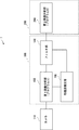
- FIG. It is a block diagram which shows the structure of the image analysis system which concerns on Embodiment 1.
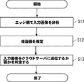
- FIG. It is a block diagram which shows the hardware configuration example of the information processing apparatus 100, 200. It is a flowchart explaining the image analysis method which concerns on Embodiment 1.
- FIG. It is a figure explaining the learning method of the difference value estimation part which concerns on Embodiment 2.
- FIG. It is a flowchart explaining the learning method of the difference value estimation part which concerns on Embodiment 2.
- FIG. It is a flowchart which shows the operation of the edge side in the video analysis system which concerns on Embodiment 2.
- the image analysis system 1 is via a camera 110, an information processing device 100 (also called an Edge device) arranged on the edge side that inputs images from the camera 110 and analyzes the image, and the information processing device 100 via a network. It includes an information processing device 200 for video analysis, which is arranged on the connected cloud server side.
- an information processing device 100 also called an Edge device
- It includes an information processing device 200 for video analysis, which is arranged on the connected cloud server side.
- the camera 110 inputs an image from an image sensor such as a CCD (Charge Coupled Device) or a CMOS (Complementary Metal Oxide Semiconductor), and outputs the input image to the first image analysis unit 103 of the information processing device 100.
- an image sensor such as a CCD (Charge Coupled Device) or a CMOS (Complementary Metal Oxide Semiconductor)
- CMOS Complementary Metal Oxide Semiconductor
- the information processing device 100 includes a first image analysis unit 103, a filter unit 104, and a difference value estimation unit 105.
- the first image analysis unit 103 analyzes the image from the camera 110 by using the image analysis program A (also called a lightweight model or a low-precision model). Further, the information processing apparatus 200 has a second image analysis unit 209 including an image analysis program B (also referred to as a high-precision model) capable of performing image analysis with higher accuracy than the image analysis program A. Examples of high-precision or lightweight models include deep neural network models and other statistical models.
- the difference value estimation unit 105 on the edge side which is one of the feature parts of the present embodiment, predicts the result when the input image is analyzed by the high-precision model of the cloud server, and is expected to improve the analysis accuracy.
- the purpose is to estimate the difference value that indicates whether it can be done. That is, the larger the difference value, the more the analysis accuracy can be improved by performing the image analysis on the cloud server.
- the difference value estimation unit 105 calculates the evaluation value of the analysis result for the input image based on the analysis result of the first image analysis unit 103. Further, the difference value estimation unit 105 uses the trained model learned in advance (details will be described later) to calculate the evaluation value when the input image is analyzed by the second image analysis unit 209.
- the difference between the evaluation value of the analysis result of the image analysis unit 103 and the evaluation value when analyzed by the second image analysis unit 209 is estimated.
- the evaluation value referred to here is a numerical value of the analysis accuracy (also referred to as reliability) for the entire input image frame.
- the filter unit 104 determines whether or not to transmit the input image frame to the second image analysis unit 209 on the cloud server side based on the difference value estimated by the difference value estimation unit 105.
- FIG. 2 is a block diagram showing a hardware configuration example of the information processing devices 100 and 200.
- the information processing devices 100 and 200 of the present embodiment are computers having a CPU (Central Processing Unit) 201, a RAM (Random access memory) 202, a ROM (Read Only Memory) 203, and the like.
- the CPU 201 performs calculations and controls according to software stored in the RAM 202, the ROM 203, or the hard disk 204.
- the RAM 202 is used as a temporary storage area when the CPU 201 executes various processes.
- the hard disk 204 stores an operating system (OS), a registration program described later, and the like.
- OS operating system
- the display 205 is composed of a liquid crystal display and a graphic controller, and the display 205 displays objects such as images and icons, a GUI, and the like.
- the input unit 206 is a device for the user to give various instructions to the terminal device 200, and is composed of, for example, a mouse or a keyboard.
- the I / F (interface) unit 207 can control wireless LAN communication and wired LAN communication corresponding to standards such as IEEE802.11a, and is based on a protocol such as TCP / IP via the same communication network and the Internet. Communicate with external devices.
- the system bus 208 controls the exchange of data with the CPU 201, the RAM 202, the ROM 203, the hard disk 204, and the like.
- the video analysis method according to the first embodiment will be described with reference to FIG.
- the evaluation value of the analysis result in the first image analysis step and the input image frame are analyzed by the cloud server.
- the difference value estimation step (step S12) for estimating the difference value from the evaluation value of the analysis result predicted in the case of the above, and the filtering for determining whether or not to send the input image frame to the cloud server based on the difference value.
- the video analysis method according to the present embodiment includes a learning method performed in advance before operating the video analysis system, and a video analysis method using the trained model.
- the image taken by the camera or the like is input to the second image analysis unit 209 capable of executing the high-precision model on the cloud server side (step S1).
- the second image analysis unit 209 analyzes the input image and calculates an evaluation value from the analysis result (step S2).
- the image taken by the camera or the like is input to the first image analysis unit 103 capable of executing the lightweight model (low-precision model) on the edge side (step S3).
- the first image analysis unit 103 analyzes the input image and calculates the evaluation value thereof (step S4).
- step S5 The difference between the evaluation value of the analysis result of the second image analysis unit 209 and the evaluation value of the analysis result of the first image analysis unit 103 calculated in parallel in this way is calculated (step S5).
- the difference value estimation unit 105 learns the calculated difference and the input image (step S6).
- the evaluation value is a numerical value of the analysis accuracy (also called reliability) for the entire input image frame.
- the entire input image frame means the input image frame itself in which a part (for example, an area including a person's face) in the input image frame is not cut out.
- an absolute difference may be used, or a relative difference may be used.
- the relative difference is (0.97-0.95) /0.95.
- the absolute difference between the input image 1 and the input image 2 is the same, but the relative difference between them is larger in the input image 2 than in the input image 1.
- the input image 2 having a large relative difference should be preferentially sent to the cloud server side.
- the accuracy of image analysis in the low-precision model and the high-performance model differs depending on the time zone (for example, daytime and nighttime), and the estimated difference value also differs. It is preferable to learn the distribution of.
- the trained model created in advance in this way is stored in the storage unit of the information processing device 100 (hard disk 204 in FIG. 2) or in the external storage unit connected to the information processing device 100 via the network.
- Examples of the model used for machine learning of the difference value estimation unit include a deep neural network model and other statistical models.
- the learning stage described above is performed before the video analysis method is implemented (before it is operated as a video analysis system).
- FIG. 6 is a block diagram showing a configuration of the video analysis system according to the second embodiment.
- FIG. 5 the same components as those in the first embodiment are designated by the same reference numerals as those in FIG. 1, and the description thereof will be omitted as appropriate.
- FIG. 7 is a flowchart showing the operation of the information processing device 100 on the edge side in the video analysis system according to the present embodiment.
- FIG. 8 is a flowchart showing the operation of the information processing device 200 on the cloud side in the video analysis system according to the present embodiment.
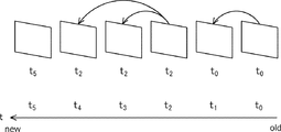
- 9A-9C are diagrams illustrating a series of frames of video transmitted in chronological order.
- a threshold value changing unit 101 is added to the information processing device 100 on the edge side according to the present embodiment.
- the threshold value changing unit 101 dynamically changes the threshold value according to a predetermined condition (details will be described later).
- an encoder 106 connected to the filter unit 104 is added to the information processing device 100 on the edge side according to the present embodiment.
- a decoder 210 is added to the information processing device 200 on the cloud side via the encoder 106 and the network 120.
- the encoder 106 uses only the frame to be transmitted to H.I. 264 and H. It is encoded by a video encoding such as 265 and transmitted.
- the encoder 106 may also be called a transmission unit.
- the information processing device 100 shown in FIG. 6 has a configuration that does not include the camera 110, the information processing device 100 may include the camera 110.
- the encoder 106 sends the same frame as the previously transmitted frame for the frame that is not transmitted.
- the decoder 210 decodes the received video and divides it into frames. Further, the decoder 210 calculates the difference from the frame in the previous stage, and if there is no difference, determines that the frame is copied by the encoder 106 and discards it.
- step S101 in FIG. 7 when the image frame obtained by dividing the image captured by the camera 110 into a plurality of frames is input to the first image analysis unit 103 equipped with the lightweight model (step S101 in FIG. 7), Image analysis is performed using the lightweight model (step S102).
- step S102 when the difference value estimation unit 105 uses the trained model and sends the evaluation value of the analysis result by the first image analysis unit 103 and the cloud server side to the input image.
- the difference (relative difference) from the evaluation value of the analysis result that will be obtained by the analysis with the high-performance model is estimated (step S103).
- the filter unit 104 compares with the difference value and sets a threshold value for determining whether or not to send the input image to the cloud server side (step S104). The details of the threshold setting method will be described later.
- the filter unit 104 compares the estimated difference value with the threshold value (step S105). When the difference value is equal to or greater than the threshold value (Y in step S105), the encoder 106 encodes the image and transmits it to the second image analysis unit 209 on the cloud server side (step S106).
- the encoder 106 copies the previously transmitted image and transmits it to the second image analysis unit 209 on the cloud server side (step S106). ..
- a series of frames of images transmitted in chronological order will be described. As shown in FIG. 9A, among a series of frames of the video transmitted in chronological order, at times t 1 , t 3 , and t 4 , it is determined that the difference value of the frames is less than the threshold value, so that frame. Is not transmitted to the cloud server (in FIG. 9A, frames that are not transmitted are indicated by dashed lines).
- the frame rate dynamically fluctuates (frames are skipped), and the encoder and decoder may not be able to perform the operation. Therefore, as shown in FIG. 9B, for the frame determined not to be transmitted, the previously transmitted frame is copied, encoded, and transmitted. That is, at t 1 , the frame at t 0 is copied and transmitted, and at t 3 and t 4 , the frame at t 2 is copied, encoded, and transmitted. In this way, as shown in FIG. 9C, the difference information between the previously transmitted frame and the copied frame becomes 0. As a result, the traffic volume after encoding becomes almost 0 (constant).
- the decoder 210 of the information processing device 200 receives the image encoded by the encoder 106 of the information processing device 100 (step S201).
- the decoder 210 decodes the received video and divides it into a plurality of time-series frames.
- FIG. 9C when it is determined that the difference between the image frame and the previous image frame is larger than 0 (Y in step S202), the frame is transmitted to the second image analysis unit 209 on the cloud server side.
- MSE Mel Squared Error
- Hash may be used.
- the second image analysis unit 209 executes image analysis with a high-precision model on the received image (step S203).
- the decoder 210 discards the frame (that is, the frame is not analyzed by the second image analysis unit 209). In this way, even if the frames are skipped, which one is copied by inserting a copy of the previously transmitted frame on the edge side and sending it to the cloud server and calculating the difference between the frames on the cloud server side. It is possible to recognize whether or not the frame is a server, and it is possible to determine whether or not analysis is necessary for each frame.
- the method of setting this threshold differs depending on the bandwidth that can be used for microbatch processing a plurality of frames and transmitting the frame from the edge side to the cloud side (hereinafter, may be referred to as an available bandwidth).
- the threshold value is dynamically set so that frames with a large value are sent with priority. As a result, it is possible to suppress the problem that block noise and frame dropping occur due to fluctuations in the usable band.
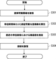
- the threshold value changing unit 101 first periodically acquires the usable band (step S301). Since the usable band can fluctuate constantly, the usable band may be acquired every second, for example.
- the number of images that can be transmitted per predetermined time (for example, unit time) in the acquired usable band is calculated (step S302). For example, the number of images that can be transmitted per unit time is calculated to be 3.
- the difference value in the latest predetermined time (for example, unit time) is estimated (step S303). For example, the most recent difference value for each frame per unit time is estimated to be [2.2, 1.1, 5.3, 3.0, 1.9, 2.6, 4.2, 3.5]. To.
- step S304 Since the number of images that can be transmitted is 3, 3.5, which is the upper third from the estimated distribution of different values, is set as the threshold value (step S304). As a result, by not sending images that are not expected to improve accuracy in image analysis on the cloud server side to the cloud server, unnecessary block noise and frame dropping can be suppressed even when using a network with bandwidth restrictions. be able to.
- the threshold value changing unit 101 since the accuracy of image analysis differs depending on the current time (that is, the distribution of the difference value for each time zone differs), the threshold value according to the current time is dynamically set. That is, for example, at night, it is difficult to recognize the object and the accuracy of image analysis deteriorates. Therefore, it is necessary to use the distribution of the difference values corresponding to the night.
- the threshold value changing unit 101 acquires the current time (for example, 23:00) (step S401). Next, the distribution of the difference values corresponding to the current time is acquired (step S402).
- the distribution curve of the difference value corresponding to the current time of 23:00 (the distribution curve of 22:00 to 5:00 shown by the broken line in FIG. 12) is acquired.
- a difference value corresponding to the top 30% of the distribution is calculated and set as a threshold value (step S403).
- the top 30% is set as the reference value, but the reference value is not limited to this. This reference value can be set to an arbitrary value that is expected to improve accuracy by sending the image to the cloud server.
- the threshold value changing unit on the edge side can dynamically change the threshold value, and can determine which video frame should be sent to the cloud server according to the situation. Further, according to the video analysis method and the video analysis system according to the present embodiment, even if a network having a bandwidth constraint is used, the edge and the cloud server can be distributed to perform high-precision video analysis.
- FIGS. 3, 7, 8 and 10 and 11 show the specific order of execution, but the order of execution may be different from the drawn form. ..
- the order of execution of two or more steps may be swapped with respect to the indicated order.
- the two or more steps shown in succession in FIGS. 3, 7, 8 and 10 and 11 may be performed simultaneously or partially simultaneously.
- one or more steps shown in FIGS. 3, 7, 8 and 10 and 11 may be skipped or omitted.
- Non-temporary computer-readable media include various types of tangible storage media.
- Examples of non-temporary computer-readable media include magnetic recording media, magneto-optical recording media (eg, magneto-optical disks), CD-ROMs (Read Only Memory), CD-Rs, CD-R / Ws, and semiconductor memories.
- the magnetic recording medium may be, for example, a flexible disk, a magnetic tape, or a hard disk drive.
- the semiconductor memory may be, for example, a mask ROM, a PROM (Programmable ROM), an EPROM (Erasable PROM), a flash ROM, or a RAM (Random Access Memory).
- the program may also be supplied to the computer by various types of temporary computer readable media.
- Examples of temporary computer-readable media include electrical, optical, and electromagnetic waves.
- the temporary computer-readable medium can supply the program to the computer via a wired communication path such as an electric wire and an optical fiber, or a wireless communication path.
- (Appendix 1) The first image analysis step to analyze the input image frame on the edge side, A difference value estimation step that estimates a difference between the evaluation value of the analysis result of the first image analysis step and the evaluation value of the analysis result predicted when the input image frame is analyzed by the cloud server.
- (Appendix 2) The video analysis method according to Appendix 1, further comprising a threshold value changing step of dynamically changing the threshold value of the difference value for making the determination.
- (Appendix 3) The video analysis method according to Appendix 2, wherein in the threshold value changing step, the current time is acquired and the threshold value is changed according to the distribution of the difference values at the current time.
- the video analysis method according to any one of Appendix 1 to 5, further comprising a step of transmitting to the cloud server.
- Appendix 7 A first image analysis means that is placed on the edge side and analyzes the input image frame, A second image analysis means, which is arranged on a cloud server via a network and has higher accuracy than the first image analysis means, The difference between the evaluation value of the analysis result of the first image analysis means arranged on the edge side and the evaluation value of the analysis result predicted when the input image frame is analyzed by the second image analysis means is set.
- Difference value estimation means to estimate and It is determined whether or not the input image frame is transmitted to the second image analysis means of the cloud server via the network based on the difference value arranged on the edge side and estimated by the difference value estimating means.
- Appendix 8 The video analysis system according to Appendix 7, further comprising a threshold value changing means for dynamically changing the threshold value of the difference value for performing the determination according to a predetermined condition.
- Appendix 9 The video analysis system according to Appendix 8, wherein the threshold value changing means acquires the current time and changes the threshold value according to the distribution of the difference values at the acquired current time.
- the threshold value changing means acquires a used band and changes the threshold value according to the number of images that can be transmitted per predetermined time in the acquired used band and a series of estimated difference values in the latest predetermined time. , The video analysis system according to Appendix 8.
- the first image analysis means that analyzes the input image frame on the edge side
- a difference value estimating means that estimates a difference between the evaluation value of the analysis result of the first image analysis means and the evaluation value of the analysis result predicted when the input image frame is analyzed by the cloud server.
- a filter means for determining whether or not to transmit the input image frame to the cloud server based on the difference value
- Information processing device The information processing apparatus according to Appendix 13, further comprising a threshold value changing means for dynamically changing the threshold value of the difference value for performing the determination.
- the information processing device according to Appendix 14, wherein the threshold value changing means acquires the current time and changes the threshold value according to the distribution of the difference values at the current time.
- the threshold value changing means acquires an available band and obtains a usable band.
- the entire input image frame determined to be sent to the cloud server by the filter means is transmitted to the cloud server, and the input image frame not determined to be sent to the cloud server by the filter means is the frame transmitted last time.
- Video analysis system 100 Information processing device 101 Threshold change unit 103 1st image analysis unit 104 Filter unit 105 Difference value estimation unit 106 Encoder 110 Camera 120 Network 200 Information processing equipment 209 2nd image analysis unit 210 Decoder
Landscapes
- Engineering & Computer Science (AREA)
- Theoretical Computer Science (AREA)
- Physics & Mathematics (AREA)
- General Physics & Mathematics (AREA)
- Multimedia (AREA)
- Computer Vision & Pattern Recognition (AREA)
- Software Systems (AREA)
- Computing Systems (AREA)
- Evolutionary Computation (AREA)
- Health & Medical Sciences (AREA)
- Artificial Intelligence (AREA)
- Databases & Information Systems (AREA)
- General Health & Medical Sciences (AREA)
- Medical Informatics (AREA)
- Quality & Reliability (AREA)
- Signal Processing (AREA)
- Image Analysis (AREA)
- Image Processing (AREA)
Priority Applications (3)
| Application Number | Priority Date | Filing Date | Title |
|---|---|---|---|
| JP2021550948A JP7103530B2 (ja) | 2019-10-07 | 2019-10-07 | 映像分析方法、映像分析システム及び情報処理装置 |
| PCT/JP2019/039453 WO2021070215A1 (ja) | 2019-10-07 | 2019-10-07 | 映像分析方法、映像分析システム及び情報処理装置 |
| US17/765,512 US12087048B2 (en) | 2019-10-07 | 2019-10-07 | Video analysis method and system, and information processing device, transmits image frame to cloud server based on difference between analysis result on the edge side and result predicted on a cloud server |
Applications Claiming Priority (1)
| Application Number | Priority Date | Filing Date | Title |
|---|---|---|---|
| PCT/JP2019/039453 WO2021070215A1 (ja) | 2019-10-07 | 2019-10-07 | 映像分析方法、映像分析システム及び情報処理装置 |
Publications (1)
| Publication Number | Publication Date |
|---|---|
| WO2021070215A1 true WO2021070215A1 (ja) | 2021-04-15 |
Family
ID=75437021
Family Applications (1)
| Application Number | Title | Priority Date | Filing Date |
|---|---|---|---|
| PCT/JP2019/039453 Ceased WO2021070215A1 (ja) | 2019-10-07 | 2019-10-07 | 映像分析方法、映像分析システム及び情報処理装置 |
Country Status (3)
| Country | Link |
|---|---|
| US (1) | US12087048B2 (https=) |
| JP (1) | JP7103530B2 (https=) |
| WO (1) | WO2021070215A1 (https=) |
Cited By (5)
| Publication number | Priority date | Publication date | Assignee | Title |
|---|---|---|---|---|
| JP2023008671A (ja) * | 2021-07-06 | 2023-01-19 | 日本電信電話株式会社 | 処理システム、処理方法及び処理プログラム |
| WO2023149174A1 (ja) * | 2022-02-02 | 2023-08-10 | ソニーグループ株式会社 | 情報処理装置、情報処理方法及びプログラム |
| WO2024079901A1 (ja) * | 2022-10-14 | 2024-04-18 | 日本電気株式会社 | 処理制御システム、処理制御装置、および処理制御方法 |
| WO2025052619A1 (ja) * | 2023-09-07 | 2025-03-13 | 日本電気株式会社 | 制御システム、制御装置及び制御方法 |
| JP7732695B1 (ja) * | 2025-01-06 | 2025-09-02 | Awl株式会社 | 画像表示システム及び画像表示プログラム |
Families Citing this family (3)
| Publication number | Priority date | Publication date | Assignee | Title |
|---|---|---|---|---|
| CN117079108B (zh) * | 2023-04-28 | 2025-10-28 | 国网山西省电力公司信息通信分公司 | 一种基于深度估计的云边协同视频流分析方法和装置 |
| CN116320536B (zh) * | 2023-05-16 | 2023-08-18 | 瀚博半导体(上海)有限公司 | 视频处理方法、装置、计算机设备及计算机可读存储介质 |
| CN118368482B (zh) * | 2024-06-18 | 2024-11-19 | 广东科学中心 | 一种基于边缘计算与人工智能分析的科普视频提取系统 |
Citations (3)
| Publication number | Priority date | Publication date | Assignee | Title |
|---|---|---|---|---|
| JP2013084130A (ja) * | 2011-10-11 | 2013-05-09 | Fujitsu Ltd | 画像認識システムおよび画像認識方法 |
| JP2013088477A (ja) * | 2011-10-13 | 2013-05-13 | Alpine Electronics Inc | 音声認識システム |
| WO2017038100A1 (ja) * | 2015-09-03 | 2017-03-09 | 日本電気株式会社 | 監視サーバ、分散処理決定方法、及びプログラムが格納された非一時的なコンピュータ可読媒体 |
Family Cites Families (7)
| Publication number | Priority date | Publication date | Assignee | Title |
|---|---|---|---|---|
| CN104041016B (zh) | 2012-02-06 | 2017-05-17 | 松下电器产业株式会社 | 服务器装置及系统控制方法 |
| JP6904481B2 (ja) * | 2018-04-26 | 2021-07-14 | 日本電気株式会社 | データ解析装置、精度推定装置、データ解析方法およびプログラム |
| JP2019215807A (ja) * | 2018-06-14 | 2019-12-19 | 日本電気株式会社 | データ制御装置、データ制御方法、およびプログラム |
| CN113380254B (zh) * | 2021-06-21 | 2024-05-24 | 枣庄福缘网络科技有限公司 | 一种基于云计算和边缘计算的语音识别方法、设备及介质 |
| KR102456189B1 (ko) * | 2021-11-23 | 2022-10-18 | 쿨사인 주식회사 | 클라우드 엣지 기반의 영상 분석 시스템 |
| US11503101B1 (en) * | 2021-12-15 | 2022-11-15 | Motorola Solutions, Inc. | Device and method for assigning video analytics tasks to computing devices |
| CN117079108B (zh) * | 2023-04-28 | 2025-10-28 | 国网山西省电力公司信息通信分公司 | 一种基于深度估计的云边协同视频流分析方法和装置 |
-
2019
- 2019-10-07 JP JP2021550948A patent/JP7103530B2/ja active Active
- 2019-10-07 WO PCT/JP2019/039453 patent/WO2021070215A1/ja not_active Ceased
- 2019-10-07 US US17/765,512 patent/US12087048B2/en active Active
Patent Citations (3)
| Publication number | Priority date | Publication date | Assignee | Title |
|---|---|---|---|---|
| JP2013084130A (ja) * | 2011-10-11 | 2013-05-09 | Fujitsu Ltd | 画像認識システムおよび画像認識方法 |
| JP2013088477A (ja) * | 2011-10-13 | 2013-05-13 | Alpine Electronics Inc | 音声認識システム |
| WO2017038100A1 (ja) * | 2015-09-03 | 2017-03-09 | 日本電気株式会社 | 監視サーバ、分散処理決定方法、及びプログラムが格納された非一時的なコンピュータ可読媒体 |
Cited By (6)
| Publication number | Priority date | Publication date | Assignee | Title |
|---|---|---|---|---|
| JP2023008671A (ja) * | 2021-07-06 | 2023-01-19 | 日本電信電話株式会社 | 処理システム、処理方法及び処理プログラム |
| JP7546254B2 (ja) | 2021-07-06 | 2024-09-06 | 日本電信電話株式会社 | 処理システム、処理方法及び処理プログラム |
| WO2023149174A1 (ja) * | 2022-02-02 | 2023-08-10 | ソニーグループ株式会社 | 情報処理装置、情報処理方法及びプログラム |
| WO2024079901A1 (ja) * | 2022-10-14 | 2024-04-18 | 日本電気株式会社 | 処理制御システム、処理制御装置、および処理制御方法 |
| WO2025052619A1 (ja) * | 2023-09-07 | 2025-03-13 | 日本電気株式会社 | 制御システム、制御装置及び制御方法 |
| JP7732695B1 (ja) * | 2025-01-06 | 2025-09-02 | Awl株式会社 | 画像表示システム及び画像表示プログラム |
Also Published As
| Publication number | Publication date |
|---|---|
| JP7103530B2 (ja) | 2022-07-20 |
| US12087048B2 (en) | 2024-09-10 |
| JPWO2021070215A1 (https=) | 2021-04-15 |
| US20220345590A1 (en) | 2022-10-27 |
Similar Documents
| Publication | Publication Date | Title |
|---|---|---|
| JP7103530B2 (ja) | 映像分析方法、映像分析システム及び情報処理装置 | |
| JP5920006B2 (ja) | 画面更新制御プログラム、画面更新制御方法、および情報処理装置 | |
| CN103636212B (zh) | 基于帧相似性和视觉质量以及兴趣的帧编码选择 | |
| US20110299589A1 (en) | Rate control in video communication via virtual transmission buffer | |
| WO2023207801A1 (zh) | 视频流帧率调整方法及其装置、设备、介质、产品 | |
| US20230247069A1 (en) | Systems and Methods for Adaptive Video Conferencing | |
| CN114374841B (zh) | 视频编码码率控制的优化方法、装置及电子设备 | |
| US20250056079A1 (en) | Method and apparatus for controlling code rate of live streaming, electronic device and storage medium | |
| CN120050421B (zh) | 基于物联网的安防监控视频实时传输方法 | |
| CN105208388B (zh) | 视频通讯中动态调整编码帧率的方法和系统 | |
| JP6365253B2 (ja) | 映像データ処理装置、映像データ処理プログラムおよび映像データ処理方法 | |
| CN113660465A (zh) | 图像处理方法、装置、可读介质及电子设备 | |
| JP2022119167A (ja) | 受信装置及びプログラム | |
| CN108074247A (zh) | 视频帧产生方法及其系统 | |
| JP2022075518A (ja) | 生産ライン監視方法および生産ライン監視システム | |
| WO2024013936A1 (ja) | 映像処理システム、映像処理装置及び映像処理方法 | |
| US12483519B2 (en) | Transmission system, transmission method and transmission program | |
| WO2024047790A1 (ja) | 映像処理システム、映像処理装置及び映像処理方法 | |
| WO2024108950A1 (zh) | 一种码流控制方法、装置及电子设备 | |
| CN115174967A (zh) | 一种基于带宽预估的码率动态分配方法 | |
| CN116827782A (zh) | 模型切换方法、装置、电子设备及存储介质 | |
| US20250292561A1 (en) | Video processing system, video processing apparatus, and video processing method | |
| WO2024057469A1 (ja) | 映像処理システム、映像処理装置および映像処理方法 | |
| CN119789115B (zh) | 通信网络中的切片信息处理方法、装置和存储介质 | |
| JP7769833B1 (ja) | 異常検出装置、および異常検出方法 |
Legal Events
| Date | Code | Title | Description |
|---|---|---|---|
| 121 | Ep: the epo has been informed by wipo that ep was designated in this application |
Ref document number: 19948775 Country of ref document: EP Kind code of ref document: A1 |
|
| ENP | Entry into the national phase |
Ref document number: 2021550948 Country of ref document: JP Kind code of ref document: A |
|
| NENP | Non-entry into the national phase |
Ref country code: DE |
|
| 122 | Ep: pct application non-entry in european phase |
Ref document number: 19948775 Country of ref document: EP Kind code of ref document: A1 |