WO2021069233A1 - Kalibrierung eines balancing-systems in einem batteriesystem - Google Patents
Kalibrierung eines balancing-systems in einem batteriesystem Download PDFInfo
- Publication number
- WO2021069233A1 WO2021069233A1 PCT/EP2020/076769 EP2020076769W WO2021069233A1 WO 2021069233 A1 WO2021069233 A1 WO 2021069233A1 EP 2020076769 W EP2020076769 W EP 2020076769W WO 2021069233 A1 WO2021069233 A1 WO 2021069233A1
- Authority
- WO
- WIPO (PCT)
- Prior art keywords
- charge
- discharge
- voltage
- cell unit
- cell
- Prior art date
- Legal status (The legal status is an assumption and is not a legal conclusion. Google has not performed a legal analysis and makes no representation as to the accuracy of the status listed.)
- Ceased
Links
Classifications
-
- H—ELECTRICITY
- H02—GENERATION; CONVERSION OR DISTRIBUTION OF ELECTRIC POWER
- H02J—ELECTRIC POWER NETWORKS; CIRCUIT ARRANGEMENTS OR SYSTEMS FOR SUPPLYING OR DISTRIBUTING ELECTRIC POWER; SYSTEMS FOR STORING ELECTRIC ENERGY
- H02J7/00—Circuit arrangements for charging or discharging batteries or for supplying loads from batteries
- H02J7/50—Circuit arrangements for charging or discharging batteries or for supplying loads from batteries acting upon multiple batteries simultaneously or sequentially
- H02J7/52—Circuit arrangements for charging or discharging batteries or for supplying loads from batteries acting upon multiple batteries simultaneously or sequentially for charge balancing, e.g. equalisation of charge between batteries
- H02J7/54—Passive balancing, e.g. using resistors or parallel MOSFETs
-
- B—PERFORMING OPERATIONS; TRANSPORTING
- B60—VEHICLES IN GENERAL
- B60L—PROPULSION OF ELECTRICALLY-PROPELLED VEHICLES; SUPPLYING ELECTRIC POWER FOR AUXILIARY EQUIPMENT OF ELECTRICALLY-PROPELLED VEHICLES; ELECTRODYNAMIC BRAKE SYSTEMS FOR VEHICLES IN GENERAL; MAGNETIC SUSPENSION OR LEVITATION FOR VEHICLES; MONITORING OPERATING VARIABLES OF ELECTRICALLY-PROPELLED VEHICLES; ELECTRIC SAFETY DEVICES FOR ELECTRICALLY-PROPELLED VEHICLES
- B60L58/00—Methods or circuit arrangements for monitoring or controlling batteries or fuel cells, specially adapted for electric vehicles
- B60L58/10—Methods or circuit arrangements for monitoring or controlling batteries or fuel cells, specially adapted for electric vehicles for monitoring or controlling batteries
- B60L58/18—Methods or circuit arrangements for monitoring or controlling batteries or fuel cells, specially adapted for electric vehicles for monitoring or controlling batteries of two or more battery modules
- B60L58/22—Balancing the charge of battery modules
-
- G—PHYSICS
- G01—MEASURING; TESTING
- G01R—MEASURING ELECTRIC VARIABLES; MEASURING MAGNETIC VARIABLES
- G01R31/00—Arrangements for testing electric properties; Arrangements for locating electric faults; Arrangements for electrical testing characterised by what is being tested not provided for elsewhere
- G01R31/36—Arrangements for testing, measuring or monitoring the electrical condition of accumulators or electric batteries, e.g. capacity or state of charge [SoC]
- G01R31/385—Arrangements for measuring battery or accumulator variables
- G01R31/387—Determining ampere-hour charge capacity or SoC
- G01R31/388—Determining ampere-hour charge capacity or SoC involving voltage measurements
-
- G—PHYSICS
- G01—MEASURING; TESTING
- G01R—MEASURING ELECTRIC VARIABLES; MEASURING MAGNETIC VARIABLES
- G01R31/00—Arrangements for testing electric properties; Arrangements for locating electric faults; Arrangements for electrical testing characterised by what is being tested not provided for elsewhere
- G01R31/36—Arrangements for testing, measuring or monitoring the electrical condition of accumulators or electric batteries, e.g. capacity or state of charge [SoC]
- G01R31/392—Determining battery ageing or deterioration, e.g. state of health
-
- G—PHYSICS
- G01—MEASURING; TESTING
- G01R—MEASURING ELECTRIC VARIABLES; MEASURING MAGNETIC VARIABLES
- G01R31/00—Arrangements for testing electric properties; Arrangements for locating electric faults; Arrangements for electrical testing characterised by what is being tested not provided for elsewhere
- G01R31/36—Arrangements for testing, measuring or monitoring the electrical condition of accumulators or electric batteries, e.g. capacity or state of charge [SoC]
- G01R31/396—Acquisition or processing of data for testing or for monitoring individual cells or groups of cells within a battery
-
- H—ELECTRICITY
- H01—ELECTRIC ELEMENTS
- H01M—PROCESSES OR MEANS, e.g. BATTERIES, FOR THE DIRECT CONVERSION OF CHEMICAL ENERGY INTO ELECTRICAL ENERGY
- H01M10/00—Secondary cells; Manufacture thereof
- H01M10/42—Methods or arrangements for servicing or maintenance of secondary cells or secondary half-cells
- H01M10/48—Accumulators combined with arrangements for measuring, testing or indicating the condition of cells, e.g. the level or density of the electrolyte
- H01M10/482—Accumulators combined with arrangements for measuring, testing or indicating the condition of cells, e.g. the level or density of the electrolyte for several batteries or cells simultaneously or sequentially
-
- H—ELECTRICITY
- H02—GENERATION; CONVERSION OR DISTRIBUTION OF ELECTRIC POWER
- H02J—ELECTRIC POWER NETWORKS; CIRCUIT ARRANGEMENTS OR SYSTEMS FOR SUPPLYING OR DISTRIBUTING ELECTRIC POWER; SYSTEMS FOR STORING ELECTRIC ENERGY
- H02J7/00—Circuit arrangements for charging or discharging batteries or for supplying loads from batteries
- H02J7/80—Circuit arrangements for charging or discharging batteries or for supplying loads from batteries including monitoring or indicating arrangements
- H02J7/82—Control of state of charge [SOC]
-
- H—ELECTRICITY
- H02—GENERATION; CONVERSION OR DISTRIBUTION OF ELECTRIC POWER
- H02J—ELECTRIC POWER NETWORKS; CIRCUIT ARRANGEMENTS OR SYSTEMS FOR SUPPLYING OR DISTRIBUTING ELECTRIC POWER; SYSTEMS FOR STORING ELECTRIC ENERGY
- H02J7/00—Circuit arrangements for charging or discharging batteries or for supplying loads from batteries
- H02J7/80—Circuit arrangements for charging or discharging batteries or for supplying loads from batteries including monitoring or indicating arrangements
- H02J7/84—Control of state of health [SOH]
-
- H—ELECTRICITY
- H01—ELECTRIC ELEMENTS
- H01M—PROCESSES OR MEANS, e.g. BATTERIES, FOR THE DIRECT CONVERSION OF CHEMICAL ENERGY INTO ELECTRICAL ENERGY
- H01M10/00—Secondary cells; Manufacture thereof
- H01M10/42—Methods or arrangements for servicing or maintenance of secondary cells or secondary half-cells
- H01M10/425—Structural combination with electronic components, e.g. electronic circuits integrated to the outside of the casing
- H01M2010/4271—Battery management systems including electronic circuits, e.g. control of current or voltage to keep battery in healthy state, cell balancing
-
- H—ELECTRICITY
- H01—ELECTRIC ELEMENTS
- H01M—PROCESSES OR MEANS, e.g. BATTERIES, FOR THE DIRECT CONVERSION OF CHEMICAL ENERGY INTO ELECTRICAL ENERGY
- H01M2220/00—Batteries for particular applications
- H01M2220/20—Batteries in motive systems, e.g. vehicle, ship, plane
-
- Y—GENERAL TAGGING OF NEW TECHNOLOGICAL DEVELOPMENTS; GENERAL TAGGING OF CROSS-SECTIONAL TECHNOLOGIES SPANNING OVER SEVERAL SECTIONS OF THE IPC; TECHNICAL SUBJECTS COVERED BY FORMER USPC CROSS-REFERENCE ART COLLECTIONS [XRACs] AND DIGESTS
- Y02—TECHNOLOGIES OR APPLICATIONS FOR MITIGATION OR ADAPTATION AGAINST CLIMATE CHANGE
- Y02E—REDUCTION OF GREENHOUSE GAS [GHG] EMISSIONS, RELATED TO ENERGY GENERATION, TRANSMISSION OR DISTRIBUTION
- Y02E60/00—Enabling technologies; Technologies with a potential or indirect contribution to GHG emissions mitigation
- Y02E60/10—Energy storage using batteries
Definitions
- the present invention relates to a method for calibrating a balancing system in a battery system.
- Battery systems for electrically or hybrid-electrically operated vehicles comprise a plurality of individual secondary cells connected in parallel and in series, typically lithium-ion cells, which are controlled by a battery management system (BMS).
- BMS battery management system
- the BMS has the function of monitoring the operating data such as cell voltage, state of charge (SoC), degree of aging (SoH, State of Health), current, temperature and controlling the charging and discharging of the cells.
- Other tasks of the BMS are the thermal management of the battery system, the protection of the cells and the prediction of the remaining service life of the cells on the basis of the recorded operating data.
- the individual cells can be connected in series in order to achieve the desired voltage, for example 200 to 400 V.
- a plurality of cells can be connected in parallel in groups, and the cell groups thus obtained are in turn connected in series.
- the cell groups connected in parallel behave like individual cells with regard to voltage or SoC monitoring as well as with regard to the balancing described in more detail below. The following are therefore individual cells and groups of individual cells connected in parallel are collectively referred to as "cell units".
- SoC state of charge
- active balancing processes charge is transferred from a cell unit with an increased SOC to a cell unit with a lower SOC. This can be done by a charge-transferring element such as a capacitor, a coil and / or a voltage converter.
- passive balancing processes on the other hand, in cells with an increased SOC, the excess charge is simply dissipated via a resistor (shunt) until the state of charge is balanced.
- the balancing charge can be determined from the cell voltage, the duration of the actuation of the balancing circuit and the characteristics of the balancing circuit itself.
- the problem here is that although the voltage profile and the time are known with good accuracy, the accuracy of the charge determination depends on the tolerance of the load resistance. For reasons of cost, the use of high-precision load resistors or individual re-measurement of the exact resistance values is out of the question for most purposes.
- the invention relates to a method for calibrating a passive balancing system in a battery system which comprises a plurality of lithium ion cells and a battery management device (BMU).
- BMU battery management device
- cell units which consist of individual cells or groups of several cells connected in parallel are each connected in series in strings.
- Each cell unit ie, individual cell or block of cells connected in parallel
- the BMU is also set up to measure the voltage Ui of each cell unit and to actuate the discharge circuit at a selectable point in time in order to discharge the cell unit i in a controlled manner via the load resistor Ri.
- the method according to the invention comprises the following steps:
- the supply of a previously known charge and its subsequent dissipation via the balancing system as well as the calculation from the voltage using the aforementioned differential capacitance Ci dQi / dUi of the cell come into consideration as alternatives.
- the calibration method according to the invention enables the exact values for the load resistances R ⁇ to be determined, which in turn determines the precise determination of the amount of charge that has flowed during balancing, which in turn can be used for diagnosis (eg for the beginning of internal fine-tuning).
- the calibration process can also be used again and again over the entire service life of the battery system without having to visit the workshop.
- FIG. 1 shows schematically the structure of a string of cell units, each of which is provided with a discharge circuit and a voltage measuring device.
- FIG. 2 shows schematically the structure when determining Q ⁇ by supplying and subsequent dissipation of a previously known charge.
- the battery system in which the method according to the invention is used comprises a plurality of lithium-ion cells and a battery management device (BMS), in which cell units made up of individual cells or groups of cells connected in parallel are each provided with a balancing circuit.
- the battery management device is set up to carry out a charge equalization, ie a balancing, at predetermined times perform.
- a charge equalization ie a balancing
- the balancing circuit is actuated in order to remove charge from this cell or cell group until the cell voltages are equalized.
- the balancing is typically carried out during a resting phase, for example after charging and at a time when the battery system is not being loaded.
- the balancing can be carried out at any time outside of the ferry service, preferably directly after the storage unit has been charged.
- ferry operation with an internal combustion engine can also be considered.
- the point in time and the exact method of balancing are not specifically restricted as long as the charge converted for each cell during balancing can be determined by the BMS.
- FIG. 1 A simplified schematic representation of such a passive balancing circuit for the case of N cells connected in series is shown in FIG.
- the cell voltage U ⁇ is monitored by the BMS.
- each cell is provided with a shunt circuit that includes at least one switch S ⁇ (e.g. a MOSFET) controlled by the BMS and the actual parallel resistor (shunt) R ⁇ .
- S ⁇ e.g. a MOSFET
- the calibration method according to the invention is used to precisely determine the resistance value R ⁇ in order to be able to precisely determine the balancing current and the charge that has flowed.
- the battery management device is able to measure U ⁇ with high precision and, if necessary, record it over time, in order to be able to monitor the state of charge (SOC) of the cell unit, for example.
- SOC state of charge
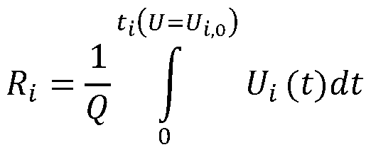
- the invention is based on the idea of determining the calibration parameter R ⁇ using the above formula by determining the duration of the actuation of the discharge circuit (discharge duration) t ⁇ , the charge Q ⁇ and the voltage profile U ⁇ ( t). R ⁇ can then be written as
- the supply of a known charge and their subsequent removal via the discharge into consideration, or the calculation are, for example, the charge from the differential capacitor and the voltage profile during discharge. Determination of Qi by applying a known charge
- a first possibility of determining Q ⁇ consists in supplying a known charge Q, which leads to an increase in the voltage Ui due to the increase in the state of charge of the cell unit.
- the discharge circuit is then actuated until the increased voltage has fallen back to the initial value.
- the state of charge (SOC) of the unit cell is again the same as before feeding of the charge, that is, is flown during discharge charge Q ⁇ corresponds to the charge supplied Q.
- SOC state of charge
- step (1) the voltage U ⁇ , o is measured, which is a measure of the initial SOC of the cell unit, which is also must be equal to the end SOC at the end of the following step (3).
- step (2) the entire string is charged with a defined charging current for a defined period of time.
- This step can be carried out with a conventional charger and differs from normal charging only in that the battery system is not fully charged, but that only a known charge Q is supplied, which is calculated by integrating the charging current over time.
- the charging method is not particularly limited.
- charging can take place with a constant current or with a constant voltage. It is only necessary to measure the course of the charging current I over time in order to be able to calculate the charge.
- the battery system or the charging device is anyway provided with a current measuring device that can be used to determine the charge.
- the current measuring device is integrated into the battery system ("S-Box"). If necessary, a high-precision current measuring device can be introduced into the charging circuit in order to be able to determine the charge with high accuracy.
- Step (2) does not require any physical access to the individual cell units, but can be carried out with the installed battery system in the field using conventional charging devices.
- a high-precision current measuring device may be required as additional equipment.
- step (3) the cell units are discharged by actuating the discharge circuit until Eh, o and thus the original SOC is reached again.
- the thereby dissipated charge Q ⁇ is thus equal to the charge supplied in step (2).
- step (4) By recording the voltage profile during the discharge and integrating it over time, the value of the load resistance R ⁇ is then calculated in step (4) as be carried out. No special laboratory equipment is required, and no external measures are required on the battery system itself.
- This embodiment of the Method according to the invention using the differential capacitance C ⁇ comprises the following steps:
- step (1) the cell is again discharged in a controlled manner and the voltage curve measured during discharging.
- the charge withdrawn is not known in advance, but has to be calculated in step (2) from the previously known differential capacitance C ⁇ and the measured voltage profile U ⁇ ( t).
- the differential capacity C ⁇ is either stored in the battery management system itself, or it is calculated on-the-fly from the previously known idling characteristic.
- step (3) R ⁇ is determined in a manner analogous to that in the first embodiment.
Landscapes
- Engineering & Computer Science (AREA)
- Power Engineering (AREA)
- General Physics & Mathematics (AREA)
- Physics & Mathematics (AREA)
- Sustainable Development (AREA)
- Sustainable Energy (AREA)
- Mechanical Engineering (AREA)
- Life Sciences & Earth Sciences (AREA)
- Transportation (AREA)
- Chemical Kinetics & Catalysis (AREA)
- Electrochemistry (AREA)
- General Chemical & Material Sciences (AREA)
- Chemical & Material Sciences (AREA)
- Manufacturing & Machinery (AREA)
- Secondary Cells (AREA)
- Charge And Discharge Circuits For Batteries Or The Like (AREA)
- Health & Medical Sciences (AREA)
- General Health & Medical Sciences (AREA)
- Medical Informatics (AREA)
Abstract
Description




Claims


Priority Applications (4)
| Application Number | Priority Date | Filing Date | Title |
|---|---|---|---|
| JP2022521241A JP7402320B2 (ja) | 2019-10-11 | 2020-09-24 | バッテリシステムにおけるバランシングシステムの校正 |
| US17/767,249 US20220385079A1 (en) | 2019-10-11 | 2020-09-24 | Calibration of a Balancing System in a Battery System |
| KR1020227010548A KR102800430B1 (ko) | 2019-10-11 | 2020-09-24 | 배터리 시스템 내에서 밸런싱-시스템의 교정 |
| CN202080069616.8A CN114586256B (zh) | 2019-10-11 | 2020-09-24 | 电池系统中的均衡系统的校准 |
Applications Claiming Priority (2)
| Application Number | Priority Date | Filing Date | Title |
|---|---|---|---|
| DE102019127408.7A DE102019127408A1 (de) | 2019-10-11 | 2019-10-11 | Kalibrierung eines Balancing-Systems in einem Batteriesystem |
| DE102019127408.7 | 2019-10-11 |
Publications (1)
| Publication Number | Publication Date |
|---|---|
| WO2021069233A1 true WO2021069233A1 (de) | 2021-04-15 |
Family
ID=72659796
Family Applications (1)
| Application Number | Title | Priority Date | Filing Date |
|---|---|---|---|
| PCT/EP2020/076769 Ceased WO2021069233A1 (de) | 2019-10-11 | 2020-09-24 | Kalibrierung eines balancing-systems in einem batteriesystem |
Country Status (6)
| Country | Link |
|---|---|
| US (1) | US20220385079A1 (de) |
| JP (1) | JP7402320B2 (de) |
| KR (1) | KR102800430B1 (de) |
| CN (1) | CN114586256B (de) |
| DE (1) | DE102019127408A1 (de) |
| WO (1) | WO2021069233A1 (de) |
Families Citing this family (2)
| Publication number | Priority date | Publication date | Assignee | Title |
|---|---|---|---|---|
| DE102018216356A1 (de) * | 2018-09-25 | 2020-03-26 | Bayerische Motoren Werke Aktiengesellschaft | Detektion abnormaler Selbstentladung von Lithiumionenzellen und Batteriesystem |
| US20240217366A1 (en) * | 2023-01-04 | 2024-07-04 | GM Global Technology Operations LLC | Battery pack balancing for multiple battery pack systems using active load management |
Citations (1)
| Publication number | Priority date | Publication date | Assignee | Title |
|---|---|---|---|---|
| DE102015205725A1 (de) * | 2015-03-30 | 2016-10-06 | Robert Bosch Gmbh | Verfahren zum Betrieb einer Batterieeinheit |
Family Cites Families (9)
| Publication number | Priority date | Publication date | Assignee | Title |
|---|---|---|---|---|
| JP2007318950A (ja) * | 2006-05-27 | 2007-12-06 | Gs Yuasa Corporation:Kk | 二次電池のセル電圧バランス装置 |
| JP2010541520A (ja) | 2007-09-20 | 2010-12-24 | ユーティーシー パワー コーポレイション | セル均衡化を有する多セルエネルギー貯蔵システム用の充電量状態計算機 |
| CN201230222Y (zh) * | 2008-07-18 | 2009-04-29 | 王玉石 | 串联蓄电池组在线均衡充电器 |
| CN101882699B (zh) * | 2010-06-28 | 2012-12-05 | 惠州市亿能电子有限公司 | 动力电池组充放电均衡控制方法 |
| KR101294378B1 (ko) * | 2011-02-22 | 2013-08-23 | 주식회사 에너닉스 | 배터리 셀 밸런싱 제어장치 및 이의 방법 |
| CN102231546B (zh) * | 2011-06-30 | 2013-07-17 | 武汉市菱电汽车电子有限责任公司 | 具有均衡充放电功能的电池管理系统及其控制方法 |
| TWI627812B (zh) * | 2013-04-05 | 2018-06-21 | 美商線性科技股份有限公司 | 電壓補償主動電池平衡的裝置、系統及方法 |
| FR3069180B1 (fr) * | 2017-07-19 | 2019-08-02 | Renault S.A.S | Procede de detection d'un defaut d'autodecharge dans une cellule de batterie |
| CN112234266B (zh) * | 2018-03-30 | 2022-11-11 | 江苏罗思韦尔电气有限公司 | 一种均衡电池组系统的电池单体电压的装置 |
-
2019
- 2019-10-11 DE DE102019127408.7A patent/DE102019127408A1/de active Pending
-
2020
- 2020-09-24 US US17/767,249 patent/US20220385079A1/en active Pending
- 2020-09-24 CN CN202080069616.8A patent/CN114586256B/zh active Active
- 2020-09-24 JP JP2022521241A patent/JP7402320B2/ja active Active
- 2020-09-24 KR KR1020227010548A patent/KR102800430B1/ko active Active
- 2020-09-24 WO PCT/EP2020/076769 patent/WO2021069233A1/de not_active Ceased
Patent Citations (1)
| Publication number | Priority date | Publication date | Assignee | Title |
|---|---|---|---|---|
| DE102015205725A1 (de) * | 2015-03-30 | 2016-10-06 | Robert Bosch Gmbh | Verfahren zum Betrieb einer Batterieeinheit |
Also Published As
| Publication number | Publication date |
|---|---|
| DE102019127408A1 (de) | 2021-04-15 |
| KR102800430B1 (ko) | 2025-04-25 |
| CN114586256B (zh) | 2026-02-03 |
| KR20220054392A (ko) | 2022-05-02 |
| CN114586256A (zh) | 2022-06-03 |
| JP2022552838A (ja) | 2022-12-20 |
| US20220385079A1 (en) | 2022-12-01 |
| JP7402320B2 (ja) | 2023-12-20 |
Similar Documents
| Publication | Publication Date | Title |
|---|---|---|
| DE10252760B4 (de) | Verfahren zur Vorhersage des Innenwiderstands einer Speicherbatterie und Überwachungseinrichtung für Speicherbatterien | |
| EP3814790B1 (de) | Verfahren und batteriemanagementsystem zum ermitteln eines gesundheitszustandes einer sekundärbatterie | |
| DE102009038663B4 (de) | Kraftwagen mit einer Mehrzahl von Batterien und Verfahren zur Batteriediagnose | |
| DE102012207815A1 (de) | Systeme und verfahren zum bestimmen von zellenkapazitätswerten in einer batterie mit vielen zellen | |
| DE102018216356A1 (de) | Detektion abnormaler Selbstentladung von Lithiumionenzellen und Batteriesystem | |
| DE102011113592A1 (de) | Verfahren und vorrichtung zum schätzen der kapazität einer batterie | |
| DE102017218715A1 (de) | Bestimmung von SOC und Temperatur einer Lithiumionenzelle mittels Impedanzspektroskopie | |
| DE102011113503A1 (de) | Verfahren und Vorrichtung zum Schätzen des Ladezustands (SOC) einer Batterie | |
| DE102009003345A1 (de) | System und Verfahren zum Abschätzen des Ladezustands eines elektrochemischen Energiespeichers | |
| DE102013000572A1 (de) | Verfahren und System zur Bestimmung der Modellparameter eines elektrochemischen Energiespeichers | |
| DE102021125478B4 (de) | Bestimmung eines alterungswerts für batterien mit strom-spannungs-zeitreihen in zeitdomäne und belastungsdomäne | |
| DE102013206189A1 (de) | Bestimmen eines Ladezustands eines Akkumulators | |
| WO2021069233A1 (de) | Kalibrierung eines balancing-systems in einem batteriesystem | |
| DE102017200548B4 (de) | Verfahren zur Ermittlung einer aktuellen Kennlinie für einen ein Kraftfahrzeug versorgenden elektrochemischen Energiespeicher, Kraftfahrzeug und Server | |
| DE102016225691A1 (de) | Hochvolt-Batterie für ein Kraftfahrzeug, insbesondere für einen Kraftwagen | |
| DE102013018405A1 (de) | Ermittlung von den Zustand einer Batterie kennzeichnenden Schätzparametern | |
| WO2022002539A1 (de) | Verfahren zum bestimmen der jeweiligen temperatur mehrerer batteriezellen einer fahrzeugbatterie durch extrapolation einer gemessenen temperatur; steuereinrichtung sowie fahrzeugbatterie | |
| DE112016002067T5 (de) | Verfahren und Überwachungseinheit zum Überwachen eines Batteriesystems | |
| DE102018129426B3 (de) | Verfahren zum aktiven Ladungsausgleich in Energiespeichern | |
| DE102014220914A1 (de) | Verfahren und Vorrichtung zur Bestimmung eines betriebspunktabhängigen Widerstandsänderungsfaktors und Fahrzeug | |
| DE102014220008A1 (de) | Verfahren zum Ausgleichen der Ladezustände einer Mehrzahl von Batteriezellen und Batteriesystem zum Durchführen eines derartigen Verfahrens | |
| DE112017001422T5 (de) | Batteriezustands-Schätzvorrichtung | |
| DE102012012765A1 (de) | Verfahren und Vorrichtung zum Laden eines elektrischen Energiespeichers | |
| EP4361655A1 (de) | Verfahren zum ermitteln eines anteils defekter batteriezellen, ein batteriesteuergerät, ein computerprogramm, ein computerlesbares speichermedium, eine batterie und ein kraftfahrzeug | |
| DE102023118664B3 (de) | Verfahren zum Ermitteln wenigstens eines Parameters für das Zellbalancing eines Energiespeichers und Balancingvorrichtung |
Legal Events
| Date | Code | Title | Description |
|---|---|---|---|
| 121 | Ep: the epo has been informed by wipo that ep was designated in this application |
Ref document number: 20780987 Country of ref document: EP Kind code of ref document: A1 |
|
| ENP | Entry into the national phase |
Ref document number: 20227010548 Country of ref document: KR Kind code of ref document: A |
|
| ENP | Entry into the national phase |
Ref document number: 2022521241 Country of ref document: JP Kind code of ref document: A |
|
| NENP | Non-entry into the national phase |
Ref country code: DE |
|
| 122 | Ep: pct application non-entry in european phase |
Ref document number: 20780987 Country of ref document: EP Kind code of ref document: A1 |