WO2021066160A1 - Three-dimensional data encoding method, three-dimensional data decoding method, three-dimensional data encoding device, and three-dimensional data decoding device - Google Patents
Three-dimensional data encoding method, three-dimensional data decoding method, three-dimensional data encoding device, and three-dimensional data decoding device Download PDFInfo
- Publication number
- WO2021066160A1 WO2021066160A1 PCT/JP2020/037589 JP2020037589W WO2021066160A1 WO 2021066160 A1 WO2021066160 A1 WO 2021066160A1 JP 2020037589 W JP2020037589 W JP 2020037589W WO 2021066160 A1 WO2021066160 A1 WO 2021066160A1
- Authority
- WO
- WIPO (PCT)
- Prior art keywords
- dimensional data
- coding
- information
- dimensional
- nodes
- Prior art date
Links
Images


Classifications
-
- G—PHYSICS
- G06—COMPUTING; CALCULATING OR COUNTING
- G06T—IMAGE DATA PROCESSING OR GENERATION, IN GENERAL
- G06T9/00—Image coding
- G06T9/40—Tree coding, e.g. quadtree, octree
-
- H—ELECTRICITY
- H04—ELECTRIC COMMUNICATION TECHNIQUE
- H04N—PICTORIAL COMMUNICATION, e.g. TELEVISION
- H04N13/00—Stereoscopic video systems; Multi-view video systems; Details thereof
- H04N13/10—Processing, recording or transmission of stereoscopic or multi-view image signals
- H04N13/106—Processing image signals
- H04N13/161—Encoding, multiplexing or demultiplexing different image signal components
-
- G—PHYSICS
- G06—COMPUTING; CALCULATING OR COUNTING
- G06T—IMAGE DATA PROCESSING OR GENERATION, IN GENERAL
- G06T9/00—Image coding
- G06T9/001—Model-based coding, e.g. wire frame
-
- G—PHYSICS
- G06—COMPUTING; CALCULATING OR COUNTING
- G06T—IMAGE DATA PROCESSING OR GENERATION, IN GENERAL
- G06T9/00—Image coding
- G06T9/004—Predictors, e.g. intraframe, interframe coding
-
- H—ELECTRICITY
- H04—ELECTRIC COMMUNICATION TECHNIQUE
- H04N—PICTORIAL COMMUNICATION, e.g. TELEVISION
- H04N19/00—Methods or arrangements for coding, decoding, compressing or decompressing digital video signals
- H04N19/50—Methods or arrangements for coding, decoding, compressing or decompressing digital video signals using predictive coding
- H04N19/597—Methods or arrangements for coding, decoding, compressing or decompressing digital video signals using predictive coding specially adapted for multi-view video sequence encoding
-
- H—ELECTRICITY
- H04—ELECTRIC COMMUNICATION TECHNIQUE
- H04N—PICTORIAL COMMUNICATION, e.g. TELEVISION
- H04N19/00—Methods or arrangements for coding, decoding, compressing or decompressing digital video signals
- H04N19/90—Methods or arrangements for coding, decoding, compressing or decompressing digital video signals using coding techniques not provided for in groups H04N19/10-H04N19/85, e.g. fractals
- H04N19/96—Tree coding, e.g. quad-tree coding
Definitions
- the present disclosure relates to a three-dimensional data coding method, a three-dimensional data decoding method, a three-dimensional data coding device, and a three-dimensional data decoding device.
- 3D data In the future, devices or services that utilize 3D data are expected to become widespread in a wide range of fields such as computer vision for autonomous operation of automobiles or robots, map information, monitoring, infrastructure inspection, or video distribution.
- the three-dimensional data is acquired by various methods such as a distance sensor such as a range finder, a stereo camera, or a combination of a plurality of monocular cameras.
- point cloud As one of the expression methods of three-dimensional data, there is an expression method called point cloud that expresses the shape of three-dimensional structure by a point cloud in three-dimensional space. In the point cloud, the position and color of the point cloud are stored. Point clouds are expected to become the mainstream method for expressing three-dimensional data, but point clouds have a very large amount of data. Therefore, in the storage or transmission of 3D data, it is essential to compress the amount of data by coding, as in the case of 2D moving images (for example, MPEG-4 AVC or HEVC standardized by MPEG). Become.
- 2D moving images for example, MPEG-4 AVC or HEVC standardized by MPEG.
- point cloud compression is partially supported by a public library (Point Cloud Library) that performs point cloud-related processing.
- Point Cloud Library a public library that performs point cloud-related processing.
- Patent Document 1 a technique for searching and displaying facilities located around a vehicle using three-dimensional map data is known (see, for example, Patent Document 1).
- the coding efficiency can be improved in the three-dimensional data coding process and the three-dimensional data decoding process.
- An object of the present disclosure is to provide a three-dimensional data coding method, a three-dimensional data decoding method, a three-dimensional data coding device, or a three-dimensional data decoding device capable of improving coding efficiency.
- the three-dimensional data coding method includes a plurality of three-dimensional points included in the point group data that belong to a layer higher than the target node in the N (N is an integer of 2 or more) branch structure. It is determined whether or not the number of first effective nodes, which is the number of effective nodes including the three-dimensional points included in the first node, is equal to or greater than a predetermined first threshold value, and the number of first effective nodes is determined. In the case of the first threshold value or more, the attribute information of the target node is subjected to the first coding including the parent node of the target node and the prediction processing using a plurality of second nodes belonging to the same hierarchy as the parent node. When the number of the first effective nodes is less than the first threshold value, the attribute information of the target node is subjected to the second coding including the prediction process using the plurality of second nodes.
- the three-dimensional data decoding method includes a plurality of third nodes belonging to a layer higher than the target node in the N (N is an integer of 2 or more) branching structure of a plurality of three-dimensional points included in the point group data. It is determined whether or not the number of first effective nodes, which is the number of effective nodes including the three-dimensional points included in one node, is equal to or greater than a predetermined first threshold, and the number of first effective nodes is the said.
- the attribute information of the target node is subjected to the first decoding including the prediction process using the parent node of the target node and a plurality of second nodes belonging to the same hierarchy as the parent node.
- the second decoding including the prediction process using the plurality of second nodes is performed on the attribute information of the target node.
- the present disclosure can provide a three-dimensional data coding method, a three-dimensional data decoding method, a three-dimensional data coding device, or a three-dimensional data decoding device that can improve the coding efficiency.
- FIG. 1 is a diagram showing a configuration of coded three-dimensional data according to the first embodiment.
- FIG. 2 is a diagram showing an example of a prediction structure between SPCs belonging to the lowest layer of GOS according to the first embodiment.
- FIG. 3 is a diagram showing an example of a prediction structure between layers according to the first embodiment.
- FIG. 4 is a diagram showing an example of the coding order of GOS according to the first embodiment.
- FIG. 5 is a diagram showing an example of the coding order of GOS according to the first embodiment.
- FIG. 6 is a diagram showing an example of meta information according to the first embodiment.
- FIG. 7 is a schematic view showing a state of transmission / reception of three-dimensional data between vehicles according to the second embodiment.
- FIG. 8 is a diagram showing an example of three-dimensional data transmitted between vehicles according to the second embodiment.
- FIG. 9 is a diagram for explaining a three-dimensional data transmission process according to the third embodiment.
- FIG. 10 is a diagram showing a configuration of the system according to the fourth embodiment.
- FIG. 11 is a block diagram of the client device according to the fourth embodiment.
- FIG. 12 is a block diagram of the server according to the fourth embodiment.
- FIG. 13 is a flowchart of the three-dimensional data creation process by the client device according to the fourth embodiment.
- FIG. 14 is a flowchart of the sensor information transmission process by the client device according to the fourth embodiment.
- FIG. 15 is a flowchart of the three-dimensional data creation process by the server according to the fourth embodiment.
- FIG. 16 is a flowchart of the three-dimensional map transmission process by the server according to the fourth embodiment.
- FIG. 17 is a diagram showing a configuration of a modified example of the system according to the fourth embodiment.
- FIG. 18 is a diagram showing a configuration of a server and a client device according to the fourth embodiment.
- FIG. 19 is a diagram showing a configuration of a server and a client device according to the fifth embodiment.
- FIG. 20 is a flowchart of processing by the client device according to the fifth embodiment.
- FIG. 21 is a diagram showing a configuration of a sensor information collection system according to the fifth embodiment.
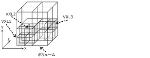
- FIG. 22 is a diagram showing an example of the volume according to the sixth embodiment.
- FIG. 23 is a diagram showing an example of an octa-tree representation of the volume according to the sixth embodiment.
- FIG. 24 is a diagram showing an example of a bit string of the volume according to the sixth embodiment.
- FIG. 25 is a diagram showing an example of an octa-tree representation of the volume according to the sixth embodiment.
- FIG. 26 is a diagram showing an example of the volume according to the sixth embodiment.
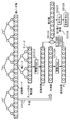
- FIG. 27 is a diagram for explaining the coding of attribute information using RAHT according to the seventh embodiment.
- FIG. 28 is a diagram showing an example in which the quantization scale is set for each layer according to the seventh embodiment.
- FIG. 29 is a diagram showing an example of a first code string and a second code string according to the seventh embodiment.
- FIG. 30 is a diagram showing an example of a truncet unity code according to the seventh embodiment.
- FIG. 31 is a diagram for explaining the inverse Har transformation according to the seventh embodiment.
- FIG. 32 is a diagram showing an example of syntax of attribute information according to the seventh embodiment.
- FIG. 33 is a diagram showing an example of the coding coefficient and ZeroCnt according to the seventh embodiment.
- FIG. 34 is a flowchart of the three-dimensional data coding process according to the seventh embodiment.
- FIG. 35 is a flowchart of the attribute information coding process according to the seventh embodiment.
- FIG. 36 is a flowchart of the coding coefficient coding process according to the seventh embodiment.
- FIG. 37 is a flowchart of the three-dimensional data decoding process according to the seventh embodiment.
- FIG. 38 is a flowchart of the attribute information decoding process according to the seventh embodiment.
- FIG. 39 is a flowchart of the coding coefficient decoding process according to the seventh embodiment.
- FIG. 40 is a block diagram of the attribute information coding unit according to the seventh embodiment.
- FIG. 41 is a block diagram of the attribute information decoding unit according to the seventh embodiment.
- FIG. 42 is a diagram showing an example of a first code string and a second code string according to a modified example of the seventh embodiment.
- FIG. 43 is a diagram showing a syntax example of attribute information according to a modified example of the seventh embodiment.
- FIG. 44 is a diagram showing examples of coding coefficients, ZeroCnt and TotalZeroCnt according to the modified example of the seventh embodiment.
- FIG. 45 is a flowchart of the coding coefficient coding process according to the modified example of the seventh embodiment.
- FIG. 46 is a flowchart of the coding coefficient decoding process according to the modified example of the seventh embodiment.
- FIG. 47 is a diagram showing a syntax example of attribute information according to a modified example of the seventh embodiment.
- FIG. 48 is a diagram showing a configuration of a three-dimensional data coding device according to the eighth embodiment.
- FIG. 49 is a diagram showing a configuration of a three-dimensional data decoding device according to the eighth embodiment.
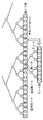
- FIG. 50 is a diagram for explaining RAHT according to the eighth embodiment.
- FIG. 51 is a diagram for explaining an integer-integer conversion according to the eighth embodiment.
- FIG. 52 is a diagram for explaining a hierarchical conversion process according to the eighth embodiment.
- FIG. 53 is a block diagram of the three-dimensional data coding apparatus according to the eighth embodiment.
- FIG. 54 is a block diagram of the lossless attribute information coding unit according to the eighth embodiment.
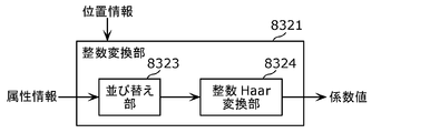
- FIG. 55 is a block diagram of the integer conversion unit according to the eighth embodiment.
- FIG. 56 is a block diagram of the three-dimensional data decoding device according to the eighth embodiment.
- FIG. 57 is a block diagram of the lossless attribute information decoding unit according to the eighth embodiment.
- FIG. 58 is a block diagram of the inverse integer conversion unit according to the eighth embodiment.
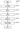
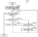
- FIG. 59 is a flowchart of the lossless attribute information coding process according to the eighth embodiment.
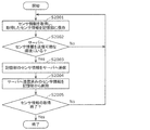
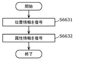
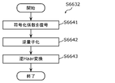
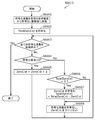
- FIG. 60 is a flowchart of the lossless attribute information decoding process according to the eighth embodiment.
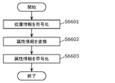
- FIG. 61 is a diagram showing a configuration example of an integer Har conversion unit according to the eighth embodiment.
- FIG. 62 is a diagram showing a configuration example of the inverse integer Har conversion unit according to the eighth embodiment.
- FIG. 63 is a diagram showing a configuration of a three-dimensional data coding device according to the eighth embodiment.
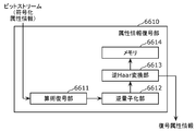
- FIG. 64 is a diagram showing a configuration of a three-dimensional data decoding device according to the eighth embodiment.
- FIG. 65 is a diagram showing a configuration of a three-dimensional data coding device according to the eighth embodiment.
- FIG. 66 is a diagram showing a configuration of a three-dimensional data decoding device according to the eighth embodiment.
- FIG. 67 is a diagram showing a configuration example of a bit stream according to the eighth embodiment.
- FIG. 68 is a diagram showing a configuration example of a bit stream according to the eighth embodiment.
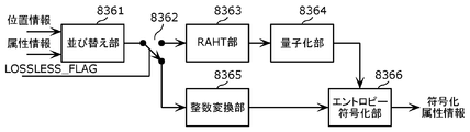
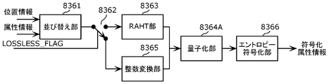
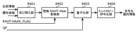
- FIG. 69 is a diagram showing a configuration of a three-dimensional data coding device according to the ninth embodiment.
- FIG. 70 is a diagram showing a configuration of a three-dimensional data decoding device according to the ninth embodiment.
- FIG. 71 is a diagram showing a configuration example of a bit stream according to the ninth embodiment.
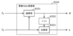
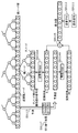
- FIG. 72 is a diagram showing a configuration example of an integer RAHT-Haar conversion unit according to the ninth embodiment.
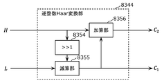
- FIG. 73 is a diagram showing a configuration example of the inverse integer RAHT-Haar conversion unit according to the ninth embodiment.
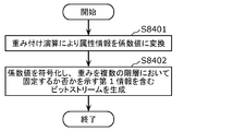
- FIG. 74 is a flowchart of the three-dimensional data coding process according to the ninth embodiment.
- FIG. 75 is a flowchart of the three-dimensional data decoding process according to the ninth embodiment.
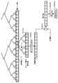
- FIG. 76 is a diagram showing a prediction process according to the tenth embodiment.
- FIG. 77 is a diagram showing the relationship of each node according to the tenth embodiment.
- FIG. 78 is a diagram showing a first example of the coding method according to the tenth embodiment.
- FIG. 79 is a diagram showing a first example of the decoding method according to the tenth embodiment.
- FIG. 80 is a diagram showing a second example of the coding method according to the tenth embodiment.
- FIG. 81 is a diagram showing a second example of the decoding method according to the tenth embodiment.
- FIG. 82 is a diagram showing a third example of the coding method according to the tenth embodiment.
- FIG. 83 is a diagram showing a third example of the decoding method according to the tenth embodiment.
- FIG. 84 is a diagram showing a fourth example of the coding method according to the tenth embodiment.
- FIG. 85 is a diagram showing a fourth example of the decoding method according to the tenth embodiment.
- FIG. 86 is a diagram showing a fifth example of the coding method according to the tenth embodiment.
- FIG. 87 is a diagram showing a fifth example of the decoding method according to the tenth embodiment.
- FIG. 88 is a flowchart of the three-dimensional data coding process according to the tenth embodiment.
- FIG. 89 is a flowchart of the three-dimensional data decoding process according to the tenth embodiment.
- FIG. 90 is a diagram showing a prediction process according to the eleventh embodiment.
- FIG. 91 is a diagram showing a first example of the coding process according to the eleventh embodiment.
- FIG. 92 is a diagram showing a first example of the decoding process according to the eleventh embodiment.
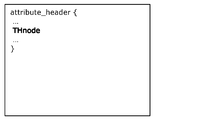
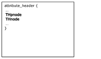
- FIG. 93 is a diagram showing a syntax example of the attribute information header according to the eleventh embodiment.
- FIG. 94 is a diagram showing a syntax example of the attribute information header according to the eleventh embodiment.
- FIG. 95 is a flowchart of the three-dimensional data coding process according to the eleventh embodiment.
- FIG. 96 is a flowchart of the three-dimensional data decoding process according to the eleventh embodiment.
- FIG. 97 is a diagram showing a second example of the coding process according to the eleventh embodiment.
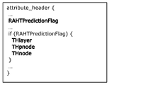
- FIG. 98 is a diagram showing an example of syntax of the attribute information header according to the eleventh embodiment.
- FIG. 99 is a diagram showing an example of syntax of the attribute information header according to the eleventh embodiment.
- FIG. 100 is a flowchart of the three-dimensional data coding process according to the eleventh embodiment.
- FIG. 101 is a flowchart of the three-dimensional data decoding process according to the eleventh embodiment.
- FIG. 102 is a diagram showing a third example of the coding process according to the eleventh embodiment.
- FIG. 103 is a diagram showing an example of syntax of the attribute information header according to the eleventh embodiment.
- FIG. 104 is a diagram showing an example of syntax of the attribute information header according to the eleventh embodiment.
- FIG. 105 is a flowchart of the three-dimensional data coding process according to the eleventh embodiment.
- FIG. 106 is a flowchart of the three-dimensional data decoding process according to the eleventh embodiment.
- FIG. 107 is a diagram showing an example of changing the reference range and the number of references according to the eleventh embodiment.
- FIG. 108 is a flowchart of the three-dimensional data coding process according to the eleventh embodiment.
- FIG. 109 is a flowchart of the three-dimensional data decoding process according to the eleventh embodiment.
- the three-dimensional data coding method includes a plurality of three-dimensional points included in the point group data that belong to a layer higher than the target node in the N (N is an integer of 2 or more) branch structure. It is determined whether or not the number of first effective nodes, which is the number of effective nodes including the three-dimensional points included in the first node, is equal to or greater than a predetermined first threshold value, and the number of first effective nodes is determined. In the case of the first threshold value or more, the attribute information of the target node is subjected to the first coding including the parent node of the target node and the prediction processing using a plurality of second nodes belonging to the same hierarchy as the parent node. When the number of the first effective nodes is less than the first threshold value, the attribute information of the target node is subjected to the second coding including the prediction process using the plurality of second nodes.
- the three-dimensional data coding method can appropriately select whether or not to use the first coding including the prediction processing, so that the coding efficiency can be improved.
- the plurality of first nodes may include the parent node and a plurality of nodes belonging to the same hierarchy as the parent node.
- the plurality of first nodes may include a grandfather node of the target node and a plurality of nodes belonging to the same hierarchy as the grandfather node.
- the predicted value of the attribute information of the target node may be set to zero.
- the three-dimensional data coding method further generates a bit stream including the coded attribute information of the target node and the first information indicating whether or not the first coding can be applied. May be good.
- the three-dimensional data coding method may further generate a bit stream including the coded attribute information of the target node and the second information indicating the first threshold value.
- a second number of effective nodes which is the number of effective nodes included in a plurality of second nodes including the grandfather node of the target node and a plurality of nodes belonging to the same hierarchy as the grandfather node, is predetermined.
- the first coding is performed on the target node.
- the second coding is performed on the attribute information of the target node. You may.
- the three-dimensional data decoding method includes a plurality of third nodes belonging to a layer higher than the target node in the N (N is an integer of 2 or more) branching structure of a plurality of three-dimensional points included in the point group data. It is determined whether or not the number of first effective nodes, which is the number of effective nodes including the three-dimensional points included in one node, is equal to or greater than a predetermined first threshold, and the number of first effective nodes is the said.
- the attribute information of the target node is subjected to the first decoding including the prediction process using the parent node of the target node and a plurality of second nodes belonging to the same hierarchy as the parent node.
- the second decoding including the prediction process using the plurality of second nodes is performed on the attribute information of the target node.
- the three-dimensional data decoding method can appropriately select whether or not to use the first decoding including the prediction processing, so that the coding efficiency can be improved.
- the plurality of first nodes may include the parent node and a plurality of nodes belonging to the same hierarchy as the parent node.
- the plurality of first nodes may include a grandfather node of the target node and a plurality of nodes belonging to the same hierarchy as the grandfather node.
- the predicted value of the attribute information of the target node may be set to zero.
- the three-dimensional data decoding method may further acquire first information indicating whether or not the first decoding is applicable from a bit stream including the coded attribute information of the target node.
- the three-dimensional data decoding method may further acquire second information indicating the first threshold value from a bit stream including encoded attribute information of the target node.
- a second number of effective nodes which is the number of effective nodes included in a plurality of second nodes including the grandfather node of the target node and a plurality of nodes belonging to the same hierarchy as the grandfather node, is predetermined.
- the first decoding is performed as an attribute of the target node. If the number of first effective nodes is less than the first threshold, or if the number of second effective nodes is less than the second threshold, the second decoding may be performed on the attribute information of the target node. Good.
- the three-dimensional data encoding device includes a processor and a memory, and the processor uses the memory to N (N) of a plurality of three-dimensional points included in the point group data. Is an integer of 2 or more)
- the number of first effective nodes which is the number of effective nodes that are nodes that include three-dimensional points, are included in a plurality of first nodes that belong to a layer higher than the target node in the branch structure. It is determined whether or not the data is equal to or higher than the first threshold, and when the number of the first effective nodes is equal to or higher than the first threshold, a plurality of second nodes including the parent node of the target node and belonging to the same hierarchy as the parent node.
- the first coding including the prediction process using the above is performed on the attribute information of the target node, and when the number of the first effective nodes is less than the first threshold value, the prediction process using the plurality of second nodes is included. No second coding is performed on the attribute information of the target node.
- the three-dimensional data coding apparatus can appropriately select whether or not to use the first coding including the prediction processing, so that the coding efficiency can be improved.
- the three-dimensional data decoding device includes a processor and a memory, and the processor uses the memory to N (N) of a plurality of three-dimensional points included in the point group data.
- N a plurality of three-dimensional points included in the point group data.
- the number of first effective nodes which is the number of effective nodes that are nodes that include three-dimensional points, included in a plurality of first nodes that belong to a layer higher than the target node in the branch structure is predetermined. If the number of first effective nodes is equal to or greater than the first threshold, a plurality of second nodes including the parent node of the target node and belonging to the same hierarchy as the parent node are included.
- the prediction processing using the plurality of second nodes is not included. 2 Decryption is performed on the attribute information of the target node.
- the three-dimensional data decoding apparatus can appropriately select whether or not to use the first decoding including the prediction processing, so that the coding efficiency can be improved.
- a recording medium such as a system, method, integrated circuit, computer program or computer-readable CD-ROM, and the system, method, integrated circuit, computer program. And any combination of recording media may be realized.
- FIG. 1 is a diagram showing a configuration of coded three-dimensional data according to the present embodiment.
- the three-dimensional space is divided into a space (SPC) corresponding to a picture in coding a moving image, and three-dimensional data is encoded in units of spaces.
- the space is further divided into volumes (VLM) corresponding to macroblocks and the like in moving image coding, and prediction and conversion are performed in units of VLM.
- the volume includes a plurality of voxels (VXL) which are the smallest units to which the position coordinates are associated.
- VXL voxels
- the prediction is the same as the prediction performed by the two-dimensional image, referring to other processing units, generating the prediction three-dimensional data similar to the processing unit of the processing target, and the prediction three-dimensional data and the processing target. It is to encode the difference from the processing unit. Further, this prediction includes not only spatial prediction that refers to other prediction units at the same time, but also time prediction that refers to prediction units at different times.
- a three-dimensional data coding device (hereinafter, also referred to as a coding device) indicates a point cloud according to the size of a voxel when encoding a three-dimensional space represented by point cloud data such as a point cloud.
- point cloud data such as a point cloud.
- Each point of the above, or a plurality of points contained in the voxel are collectively encoded. If the voxel is subdivided, the three-dimensional shape of the point cloud can be expressed with high accuracy, and if the size of the voxel is increased, the three-dimensional shape of the point cloud can be roughly expressed.
- the three-dimensional data is a point cloud
- the three-dimensional data is not limited to the point cloud and may be any form of three-dimensional data.
- a hierarchical voxel may be used.
- the nth-order layer it may be indicated in order whether or not the sample points exist in the n-1th-order or lower layer (the lower layer of the nth-order layer).
- the sample point can be regarded as existing in the center of the voxel in the nth-order layer and can be decoded.
- the coding device acquires point group data using a distance sensor, a stereo camera, a monocular camera, a gyro, an inertial sensor, or the like.
- the intra space that can be decoded independently
- the predictive space that can be referred only in one direction
- the bidirectional reference are possible as in the coding of the moving image. It falls into one of at least three predictive structures, including bidirectional spaces (B-SPCs).
- the space has two types of time information, a decoding time and a display time.
- GOS Group Of Space
- WLD world
- the spatial area occupied by the world is associated with the absolute position on the earth by GPS or latitude and longitude information. This position information is stored as meta information.
- the meta information may be included in the coded data or may be transmitted separately from the coded data.
- all SPCs may be three-dimensionally adjacent to each other, or there may be SPCs that are not three-dimensionally adjacent to other SPCs.
- processing such as coding, decoding or reference of three-dimensional data included in a processing unit such as GOS, SPC or VLM is also described as simply encoding, decoding or referencing the processing unit.
- the three-dimensional data included in the processing unit includes, for example, at least one set of a spatial position such as three-dimensional coordinates and a characteristic value such as color information.
- a plurality of SPCs in the same GOS or a plurality of VLMs in the same SPC occupy different spaces from each other, but have the same time information (decoding time and display time).
- the SPC that is the first in the decoding order in GOS is I-SPC.
- GOS there are two types of GOS, closed GOS and open GOS.
- the closed GOS is a GOS capable of decoding all the SPCs in the GOS when the decoding is started from the head I-SPC.
- the open GOS some SPCs whose display time is earlier than the first I-SPC in the GOS refer to a different GOS, and decoding cannot be performed only by the GOS.
- WLD may be decoded from the direction opposite to the coding order, and if there is a dependency between GOS, it is difficult to reproduce in the reverse direction. Therefore, in such a case, closed GOS is basically used.
- the GOS has a layer structure in the height direction, and coding or decoding is performed in order from the SPC of the lower layer.
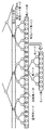
- FIG. 2 is a diagram showing an example of a prediction structure between SPCs belonging to the lowest layer of GOS.
- FIG. 3 is a diagram showing an example of a prediction structure between layers.
- I-SPCs there is one or more I-SPCs in the GOS.
- Objects such as humans, animals, cars, bicycles, traffic lights, and landmark buildings exist in the three-dimensional space, but it is effective to encode the objects, which are particularly small in size, as ISPCs.
- a three-dimensional data decoding device (hereinafter, also referred to as a decoding device) decodes only the ISPC in the GOS when decoding the GOS with a low processing amount or a high speed.
- the coding device may switch the coding interval or appearance frequency of the I-SPC according to the density of the objects in the WLD.
- the coding device or the decoding device encodes or decodes a plurality of layers in order from the lower layer (layer 1). This makes it possible to raise the priority of data near the ground, which has a larger amount of information for, for example, an autonomous vehicle.
- coded data used in a drone or the like may be coded or decoded in order from the SPC of the upper layer in the height direction in the GOS.
- the coding device or the decoding device may encode or decode a plurality of layers so that the decoding device can roughly grasp the GOS and gradually increase the resolution.
- the coding device or decoding device may encode or decode in the order of layers 3, 8, 1, 9 ...
- static objects or scenes such as buildings or roads
- dynamic objects such as cars or humans
- Object detection is performed separately by extracting feature points from point cloud data or camera images such as stereo cameras.
- the first method is a method of encoding a static object and a dynamic object without distinguishing them.
- the second method is a method of distinguishing between a static object and a dynamic object by identification information.
- GOS is used as an identification unit.
- the GOS including the SPC constituting the static object and the GOS including the SPC constituting the dynamic object are distinguished by the identification information stored in the coded data or separately from the coded data.
- the SPC may be used as the identification unit.
- the SPC including the VLM that constitutes the static object and the SPC that includes the VLM that constitutes the dynamic object are distinguished by the above identification information.
- VLM or VXL may be used as the identification unit.
- the VLM or VXL including the static object and the VLM or VXL including the dynamic object are distinguished by the above identification information.
- the coding device may encode the dynamic object as one or more VLMs or SPCs, and encode the VLM or SPC including the static object and the SPC including the dynamic object as different GOSs. Further, when the size of the GOS is variable according to the size of the dynamic object, the encoding device separately stores the size of the GOS as meta information.
- the coding device may encode the static object and the dynamic object independently of each other, and superimpose the dynamic object on the world composed of the static objects.
- the dynamic object is composed of one or more SPCs, and each SPC is associated with one or more SPCs constituting the static object on which the SPC is superimposed.
- the dynamic object may be represented by one or more VLMs or VXLs instead of the SPC.
- the coding device may encode the static object and the dynamic object as different streams.
- the coding device may generate a GOS including one or more SPCs constituting a dynamic object. Further, the coding apparatus may set the GOS (GOS_M) including the dynamic object and the GOS of the static object corresponding to the spatial area of GOS_M to the same size (occupy the same spatial area). As a result, the superimposition processing can be performed in units of GOS.
- the P-SPC or B-SPC constituting the dynamic object may refer to the SPC included in different encoded GOS.
- a reference across the GOS is effective from the viewpoint of compression ratio.
- the above-mentioned first method and the second method may be switched depending on the use of the coded data. For example, when the coded three-dimensional data is used as a map, it is desirable that the dynamic objects can be separated, so the coding device uses the second method. On the other hand, the coding device uses the first method when it is not necessary to separate the dynamic objects when coding the three-dimensional data of an event such as a concert or a sport.
- the decoding time and the display time of the GOS or SPC can be stored in the coded data or as meta information. Moreover, the time information of all static objects may be the same. At this time, the actual decoding time and the display time may be determined by the decoding device. Alternatively, a different value may be assigned to each GOS or SPC as the decoding time, and the same value may be assigned as the display time. Further, like a decoder model in moving image coding such as HEVC's HRD (Hypothetical Reference Decorder), if the decoder has a buffer of a predetermined size and reads a bit stream at a predetermined bit rate according to the decoding time, it can be decoded without failure. A model that guarantees may be introduced.
- HRD Hypothetical Reference Decorder
- the coordinates of the three-dimensional space in the world are represented by three coordinate axes (x-axis, y-axis, and z-axis) that are orthogonal to each other.
- coding can be performed so that spatially adjacent GOSs are continuous in the coded data.
- the GOS in the xz plane is continuously encoded.
- the y-axis value is updated after the coding of all GOS in a certain xz plane is completed. That is, as the coding progresses, the world extends in the y-axis direction.
- the GOS index number is set in the coding order.
- the three-dimensional space of the world is associated with GPS or geographical absolute coordinates such as latitude and longitude on a one-to-one basis.
- the three-dimensional space may be represented by a position relative to a preset reference position.
- the x-axis, y-axis, and z-axis directions of the three-dimensional space are expressed as direction vectors determined based on latitude, longitude, and the like, and the direction vectors are stored together with coded data as meta information.
- the size of GOS is fixed, and the encoding device stores the size as meta information. Further, the size of the GOS may be switched depending on, for example, whether it is an urban area or indoors or outdoors. That is, the size of the GOS may be switched depending on the amount or nature of the objects that are valuable as information.
- the coding device may adaptively switch the size of the GOS or the interval of the I-SPC in the GOS according to the density of objects and the like in the same world. For example, the coding device reduces the size of the GOS and shortens the interval between I-SPCs in the GOS as the density of objects increases.
- the GOS is subdivided in order to realize random access with fine granularity.
- the 7th to 10th GOSs are located behind the 3rd to 6th GOSs, respectively.
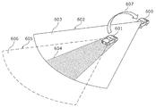
- FIG. 7 is a schematic diagram showing a state of transmission / reception of three-dimensional data 607 between the own vehicle 600 and the peripheral vehicle 601.
- the sensor of the own vehicle 600 When acquiring 3D data using a sensor mounted on the own vehicle 600 (a distance sensor such as a range finder, a stereo camera, or a combination of a plurality of monocular cameras), the sensor of the own vehicle 600 due to an obstacle such as a peripheral vehicle 601 An area within the detection range 602 but where three-dimensional data cannot be created (hereinafter, this is referred to as an occlusion area 604) is generated. Further, the accuracy of the autonomous operation increases as the space for acquiring the three-dimensional data increases, but the sensor detection range of the own vehicle 600 alone is finite.
- a distance sensor such as a range finder, a stereo camera, or a combination of a plurality of monocular cameras
- the sensor detection range 602 of the own vehicle 600 includes an area 603 in which three-dimensional data can be acquired and an occlusion area 604.
- the range in which the own vehicle 600 wants to acquire three-dimensional data includes the sensor detection range 602 of the own vehicle 600 and other areas.
- the sensor detection range 605 of the peripheral vehicle 601 includes an occlusion area 604 and a region 606 not included in the sensor detection range 602 of the own vehicle 600.
- the peripheral vehicle 601 transmits the information detected by the peripheral vehicle 601 to the own vehicle 600.
- the own vehicle 600 acquires the three-dimensional data 607 of the occlusion area 604 and the area 606 other than the sensor detection range 602 of the own vehicle 600 by acquiring the information detected by the peripheral vehicle 601 such as the vehicle in front. Is possible.
- the own vehicle 600 complements the three-dimensional data of the occlusion area 604 and the area 606 outside the sensor detection range by using the information acquired by the peripheral vehicle 601.
- 3D data in the autonomous operation of vehicles or robots is for self-position estimation, detection of surrounding conditions, or both.
- self-position estimation three-dimensional data generated by the own vehicle 600 based on the sensor information of the own vehicle 600 is used.
- the three-dimensional data acquired from the peripheral vehicle 601 is also used to detect the surrounding situation.
- the peripheral vehicle 601 that transmits the three-dimensional data 607 to the own vehicle 600 may be determined according to the state of the own vehicle 600.
- the peripheral vehicle 601 is a front-running vehicle when the own vehicle 600 goes straight, an oncoming vehicle when the own vehicle 600 turns right, and a rear vehicle when the own vehicle 600 reverses.
- the driver of the own vehicle 600 may directly specify the peripheral vehicle 601 for transmitting the three-dimensional data 607 to the own vehicle 600.
- the own vehicle 600 may search for a peripheral vehicle 601 that possesses three-dimensional data in an area that cannot be acquired by the own vehicle 600, which is included in the space in which the three-dimensional data 607 is desired to be acquired.
- the area that cannot be acquired by the own vehicle 600 is an occlusion area 604, an area 606 outside the sensor detection range 602, and the like.
- the own vehicle 600 may specify the occlusion area 604 based on the sensor information of the own vehicle 600. For example, the own vehicle 600 identifies an area within the sensor detection range 602 of the own vehicle 600 where three-dimensional data cannot be created as an occlusion area 604.
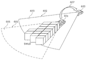
- FIG. 8 is a diagram showing an example of three-dimensional data to be transmitted in this case.
- the three-dimensional data 607 transmitted from the vehicle in front is, for example, a point cloud sparse world (SWLD). That is, the preceding vehicle creates WLD three-dimensional data (point cloud) from the information detected by the sensor of the preceding vehicle, and extracts data having a feature amount equal to or greater than the threshold value from the WLD three-dimensional data to SWLD. Create 3D data (point cloud) of. Then, the preceding vehicle transmits the created three-dimensional data of SWLD to the own vehicle 600.
- SWLD point cloud sparse world
- the own vehicle 600 receives the SWLD and merges the received SWLD with the point cloud created by the own vehicle 600.
- the transmitted SWLD has information on absolute coordinates (the position of the SWLD in the coordinate system of the three-dimensional map).
- the own vehicle 600 can realize the merge process by overwriting the point cloud generated by the own vehicle 600 based on the absolute coordinates.
- the SWLD transmitted from the peripheral vehicle 601 is the SWLD of the area 606 outside the sensor detection range 602 of the own vehicle 600 and within the sensor detection range 605 of the peripheral vehicle 601 or the SWLD of the occlusion area 604 for the own vehicle 600. Both SWLDs may be used. Further, the SWLD to be transmitted may be the SWLD in the region of the above SWLDs used by the peripheral vehicle 601 to detect the peripheral situation.
- the peripheral vehicle 601 may change the density of the point cloud to be transmitted according to the communicable time based on the speed difference between the own vehicle 600 and the peripheral vehicle 601. For example, when the speed difference is large and the communicable time is short, the peripheral vehicle 601 can reduce the density (data amount) of the point cloud by extracting three-dimensional points having a large feature amount from the SWLD. Good.
- the detection of the surrounding situation is to determine the presence or absence of people, vehicles, equipment for road construction, etc., identify the type, and detect the position, moving direction, moving speed, and the like. ..
- the own vehicle 600 may acquire the braking information of the peripheral vehicle 601 instead of the three-dimensional data 607 generated by the peripheral vehicle 601 or in addition to the three-dimensional data 607.
- the braking information of the peripheral vehicle 601 is, for example, information indicating that the accelerator or the brake of the peripheral vehicle 601 has been stepped on, or the degree thereof.
- the three-dimensional space is subdivided into random access units in consideration of low-delay communication between vehicles.
- the three-dimensional map or the like which is the map data downloaded from the server, the three-dimensional space is divided into large random access units as compared with the case of inter-vehicle communication.
- the data in the area that tends to be an occlusion area is divided into fine random access units as low-delay data.
- each vehicle Since the importance of the front is increasing when driving at high speed, each vehicle creates a SWLD with a narrow viewing angle in small random access units when driving at high speed.
- the preceding vehicle can reduce the transmission amount by removing the point cloud in that area. Good.
- FIG. 9 is a diagram showing an example of a target space of three-dimensional data to be transmitted to a following vehicle or the like.
- the vehicle 801 uses three-dimensional data such as a point cloud (point cloud) included in a rectangular parallelepiped space 802 having a width W, a height H, and a depth D at a distance L from the vehicle 801 in front of the vehicle 801 for a time of ⁇ t. At intervals, it is sent to the traffic monitoring cloud that monitors the road conditions or to the following vehicle.
- a point cloud point cloud
- the vehicle 801 refers to the three-dimensional data of the changed space. Also send.
- FIG. 9 shows an example in which the shape of the space 802 is a rectangular parallelepiped
- the space 802 may include a space on the front road which is a blind spot from the following vehicle, and does not necessarily have to be a rectangular parallelepiped. ..
- the distance L be set to a distance at which the following vehicle that has received the three-dimensional data can safely stop.
- the width W is set to a value larger than at least the width of the lane in which the vehicle 801 is traveling. More preferably, the width W is set to a size that includes adjacent spaces such as left and right lanes or roadside zones.
- the capacity of the three-dimensional data transmitted can be effectively reduced, and communication delay and cost can be reduced. it can.
- FIG. 10 is a diagram showing a configuration of a three-dimensional map and a sensor information transmission / reception system according to the present embodiment.
- the system includes a server 901 and client devices 902A and 902B.
- client devices 902A and 902B are not particularly distinguished, they are also referred to as the client devices 902.
- the client device 902 is, for example, an in-vehicle device mounted on a moving body such as a vehicle.
- the server 901 is, for example, a traffic monitoring cloud or the like, and can communicate with a plurality of client devices 902.
- the server 901 transmits a three-dimensional map composed of a point cloud to the client device 902.
- the configuration of the three-dimensional map is not limited to the point cloud, and may represent other three-dimensional data such as a mesh structure.
- the client device 902 transmits the sensor information acquired by the client device 902 to the server 901.
- the sensor information includes, for example, at least one of LiDAR acquisition information, visible light image, infrared image, depth image, sensor position information, and speed information.
- the data sent and received between the server 901 and the client device 902 may be compressed to reduce the data, or may remain uncompressed to maintain the accuracy of the data.
- a three-dimensional compression method based on an octa-tree structure can be used for the point cloud.
- a two-dimensional image compression method can be used for visible light images, infrared images, and depth images.
- the two-dimensional image compression method is, for example, MPEG-4 AVC or HEVC standardized by MPEG.
- the server 901 transmits the three-dimensional map managed by the server 901 to the client device 902 in response to the transmission request of the three-dimensional map from the client device 902.
- the server 901 may transmit the three-dimensional map without waiting for the three-dimensional map transmission request from the client device 902.
- the server 901 may broadcast a three-dimensional map to one or more client devices 902 in a predetermined space.
- the server 901 may transmit a three-dimensional map suitable for the position of the client device 902 to the client device 902 that has received the transmission request once at regular intervals.
- the server 901 may transmit the three-dimensional map to the client device 902 every time the three-dimensional map managed by the server 901 is updated.
- the client device 902 issues a three-dimensional map transmission request to the server 901. For example, when the client device 902 wants to perform self-position estimation during traveling, the client device 902 transmits a three-dimensional map transmission request to the server 901.
- the client device 902 may issue a three-dimensional map transmission request to the server 901.
- the client device 902 may issue a transmission request for the three-dimensional map to the server 901.
- the client device 902 may issue a three-dimensional map transmission request to the server 901.
- the client device 902 may issue a three-dimensional map transmission request to the server 901 before a certain time when the client device 902 goes out. For example, when the client device 902 exists within a predetermined distance from the boundary of the space indicated by the three-dimensional map held by the client device 902, the client device 902 issues a three-dimensional map transmission request to the server 901. You may. If the movement route and movement speed of the client device 902 are known, the time when the client device 902 goes out is predicted from the space shown by the three-dimensional map held by the client device 902. You may.
- the client device 902 may issue a three-dimensional map transmission request to the server 901.
- the client device 902 transmits the sensor information to the server 901 in response to the sensor information transmission request transmitted from the server 901.
- the client device 902 may send the sensor information to the server 901 without waiting for the sensor information transmission request from the server 901. For example, once the client device 902 receives a request for transmitting sensor information from the server 901, the client device 902 may periodically transmit the sensor information to the server 901 for a certain period of time. Further, when the error at the time of positioning the three-dimensional data created by the client device 902 based on the sensor information and the three-dimensional map obtained from the server 901 is equal to or more than a certain value, the client device 902 is located around the client device 902. It may be determined that the three-dimensional map may have changed, and that fact and the sensor information may be transmitted to the server 901.
- the server 901 issues a sensor information transmission request to the client device 902.
- the server 901 receives the position information of the client device 902 such as GPS from the client device 902.
- the server 901 determines that the client device 902 is approaching a space with little information in the three-dimensional map managed by the server 901 based on the position information of the client device 902
- the server 901 determines that the client device 902 is approaching a space with little information, and the client 901 generates a new three-dimensional map.
- a request for transmitting sensor information is sent to the device 902.
- the server 901 issues a sensor information transmission request when it wants to update the three-dimensional map, when it wants to check the road condition such as when it snows or when there is a disaster, when it wants to check the traffic jam situation, or when it wants to check the incident accident situation. May be good.
- the client device 902 may set the data amount of the sensor information to be transmitted to the server 901 according to the communication state or the band at the time of receiving the transmission request of the sensor information received from the server 901.
- Setting the amount of sensor information data to be transmitted to the server 901 means, for example, increasing or decreasing the data itself, or appropriately selecting a compression method.
- FIG. 11 is a block diagram showing a configuration example of the client device 902.
- the client device 902 receives a three-dimensional map composed of a point cloud or the like from the server 901, and estimates the self-position of the client device 902 from the three-dimensional data created based on the sensor information of the client device 902. Further, the client device 902 transmits the acquired sensor information to the server 901.
- the client device 902 includes a data reception unit 1011, a communication unit 1012, a reception control unit 1013, a format conversion unit 1014, a plurality of sensors 1015, a three-dimensional data creation unit 1016, a three-dimensional image processing unit 1017, and the like. It includes a three-dimensional data storage unit 1018, a format conversion unit 1019, a communication unit 1020, a transmission control unit 1021, and a data transmission unit 1022.
- the data receiving unit 1011 receives the three-dimensional map 1031 from the server 901.
- the three-dimensional map 1031 is data including a point cloud such as WLD or SWLD.
- the three-dimensional map 1031 may include either compressed data or uncompressed data.
- the communication unit 1012 communicates with the server 901 and transmits a data transmission request (for example, a three-dimensional map transmission request) or the like to the server 901.
- a data transmission request for example, a three-dimensional map transmission request
- the reception control unit 1013 exchanges information such as the corresponding format with the communication destination via the communication unit 1012, and establishes communication with the communication destination.
- the format conversion unit 1014 generates the three-dimensional map 1032 by performing format conversion or the like on the three-dimensional map 1031 received by the data receiving unit 1011. Further, the format conversion unit 1014 performs decompression or decoding processing when the three-dimensional map 1031 is compressed or encoded. If the three-dimensional map 1031 is uncompressed data, the format conversion unit 1014 does not perform decompression or decoding processing.
- the plurality of sensors 1015 are a group of sensors that acquire information outside the vehicle on which the client device 902 is mounted, such as a LiDAR, a visible light camera, an infrared camera, or a depth sensor, and generate sensor information 1033.
- the sensor information 1033 is three-dimensional data such as a point cloud (point cloud data) when the sensor 1015 is a laser sensor such as LiDAR.
- the number of sensors 1015 does not have to be plural.
- the three-dimensional data creation unit 1016 creates three-dimensional data 1034 around the own vehicle based on the sensor information 1033. For example, the three-dimensional data creation unit 1016 creates point cloud data with color information around the own vehicle by using the information acquired by LiDAR and the visible light image obtained by the visible light camera.
- the three-dimensional image processing unit 1017 uses the received three-dimensional map 1032 such as a point cloud and the three-dimensional data 1034 around the own vehicle generated from the sensor information 1033 to perform self-position estimation processing of the own vehicle and the like. ..
- the three-dimensional image processing unit 1017 creates three-dimensional data 1035 around the own vehicle by synthesizing the three-dimensional map 1032 and the three-dimensional data 1034, and estimates the self-position using the created three-dimensional data 1035. Processing may be performed.
- the three-dimensional data storage unit 1018 stores the three-dimensional map 1032, the three-dimensional data 1034, the three-dimensional data 1035, and the like.
- the format conversion unit 1019 generates the sensor information 1037 by converting the sensor information 1033 into a format supported by the receiving side.
- the format conversion unit 1019 may reduce the amount of data by compressing or encoding the sensor information 1037. Further, the format conversion unit 1019 may omit the process when it is not necessary to perform the format conversion. Further, the format conversion unit 1019 may control the amount of data to be transmitted according to the designation of the transmission range.
- the communication unit 1020 communicates with the server 901 and receives a data transmission request (sensor information transmission request) and the like from the server 901.
- the transmission control unit 1021 exchanges information such as compatible formats with the communication destination via the communication unit 1020 to establish communication.
- the data transmission unit 1022 transmits the sensor information 1037 to the server 901.
- the sensor information 1037 includes a plurality of sensors such as information acquired by LiDAR, a brightness image acquired by a visible light camera, an infrared image acquired by an infrared camera, a depth image acquired by a depth sensor, sensor position information, and speed information. Contains information acquired by 1015.
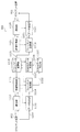
- FIG. 12 is a block diagram showing a configuration example of the server 901.
- the server 901 receives the sensor information transmitted from the client device 902, and creates three-dimensional data based on the received sensor information.
- the server 901 updates the three-dimensional map managed by the server 901 by using the created three-dimensional data. Further, the server 901 transmits the updated three-dimensional map to the client device 902 in response to the transmission request of the three-dimensional map from the client device 902.
- the server 901 includes a data reception unit 1111, a communication unit 1112, a reception control unit 1113, a format conversion unit 1114, a three-dimensional data creation unit 1116, a three-dimensional data synthesis unit 1117, and a three-dimensional data storage unit 1118. , A format conversion unit 1119, a communication unit 1120, a transmission control unit 1121, and a data transmission unit 1122.
- the data receiving unit 1111 receives the sensor information 1037 from the client device 902.
- the sensor information 1037 includes, for example, information acquired by LiDAR, a brightness image acquired by a visible light camera, an infrared image acquired by an infrared camera, a depth image acquired by a depth sensor, sensor position information, speed information, and the like.
- the communication unit 1112 communicates with the client device 902 and transmits a data transmission request (for example, a sensor information transmission request) or the like to the client device 902.
- a data transmission request for example, a sensor information transmission request
- the reception control unit 1113 exchanges information such as the corresponding format with the communication destination via the communication unit 1112 to establish communication.
- the format conversion unit 1114 When the received sensor information 1037 is compressed or encoded, the format conversion unit 1114 generates the sensor information 1132 by performing decompression or decoding processing. If the sensor information 1037 is uncompressed data, the format conversion unit 1114 does not perform decompression or decoding processing.
- the three-dimensional data creation unit 1116 creates three-dimensional data 1134 around the client device 902 based on the sensor information 1132. For example, the three-dimensional data creation unit 1116 creates point cloud data with color information around the client device 902 using the information acquired by LiDAR and the visible light image obtained by the visible light camera.
- the three-dimensional data synthesis unit 1117 updates the three-dimensional map 1135 by synthesizing the three-dimensional data 1134 created based on the sensor information 1132 with the three-dimensional map 1135 managed by the server 901.
- the three-dimensional data storage unit 1118 stores the three-dimensional map 1135 and the like.
- the format conversion unit 1119 generates the 3D map 1031 by converting the 3D map 1135 into a format supported by the receiving side.
- the format conversion unit 1119 may reduce the amount of data by compressing or encoding the three-dimensional map 1135. Further, the format conversion unit 1119 may omit the process when it is not necessary to perform the format conversion. Further, the format conversion unit 1119 may control the amount of data to be transmitted according to the designation of the transmission range.
- the communication unit 1120 communicates with the client device 902 and receives a data transmission request (three-dimensional map transmission request) or the like from the client device 902.
- the transmission control unit 1121 exchanges information such as the corresponding format with the communication destination via the communication unit 1120 to establish communication.
- the data transmission unit 1122 transmits the three-dimensional map 1031 to the client device 902.
- the three-dimensional map 1031 is data including a point cloud such as WLD or SWLD.
- the three-dimensional map 1031 may include either compressed data or uncompressed data.
- FIG. 13 is a flowchart showing an operation when the client device 902 acquires a three-dimensional map.
- the client device 902 requests the server 901 to transmit a three-dimensional map (point cloud, etc.) (S1001). At this time, the client device 902 may request the server 901 to transmit a three-dimensional map related to the position information by transmitting the position information of the client device 902 obtained by GPS or the like together.
- a three-dimensional map point cloud, etc.
- the client device 902 receives the three-dimensional map from the server 901 (S1002). If the received 3D map is compressed data, the client device 902 decodes the received 3D map to generate an uncompressed 3D map (S1003).
- the client device 902 creates three-dimensional data 1034 around the client device 902 from the sensor information 1033 obtained by the plurality of sensors 1015 (S1004).
- the client device 902 estimates the self-position of the client device 902 using the three-dimensional map 1032 received from the server 901 and the three-dimensional data 1034 created from the sensor information 1033 (S1005).
- FIG. 14 is a flowchart showing an operation at the time of transmission of sensor information by the client device 902.
- the client device 902 receives the sensor information transmission request from the server 901 (S1011).
- the client device 902 transmits the sensor information 1037 to the server 901 (S1012).
- the sensor information 1033 includes a plurality of information obtained by the plurality of sensors 1015
- the client device 902 may generate the sensor information 1037 by compressing each information by a compression method suitable for each information. Good.
- FIG. 15 is a flowchart showing an operation when the server 901 acquires sensor information.
- the server 901 requests the client device 902 to transmit the sensor information (S1021).
- the server 901 receives the sensor information 1037 transmitted from the client device 902 in response to the request (S1022).
- the server 901 creates three-dimensional data 1134 using the received sensor information 1037 (S1023).
- the server 901 reflects the created three-dimensional data 1134 on the three-dimensional map 1135 (S1024).
- FIG. 16 is a flowchart showing the operation when the server 901 transmits the three-dimensional map.
- the server 901 receives a three-dimensional map transmission request from the client device 902 (S1031).
- the server 901 that has received the three-dimensional map transmission request transmits the three-dimensional map 1031 to the client device 902 (S1032).
- the server 901 may extract a three-dimensional map in the vicinity thereof according to the position information of the client device 902 and transmit the extracted three-dimensional map.
- the server 901 may compress the three-dimensional map composed of the point cloud by using, for example, a compression method based on an octree structure, and transmit the compressed three-dimensional map.
- the server 901 creates three-dimensional data 1134 near the position of the client device 902 using the sensor information 1037 received from the client device 902. Next, the server 901 calculates the difference between the three-dimensional data 1134 and the three-dimensional map 1135 by matching the created three-dimensional data 1134 with the three-dimensional map 1135 of the same area managed by the server 901. .. When the difference is equal to or greater than a predetermined threshold value, the server 901 determines that some abnormality has occurred in the vicinity of the client device 902. For example, when land subsidence occurs due to a natural disaster such as an earthquake, a large difference occurs between the 3D map 1135 managed by the server 901 and the 3D data 1134 created based on the sensor information 1037. Can be considered.
- the sensor information 1037 may include information indicating at least one of the sensor type, the sensor performance, and the sensor model number. Further, a class ID or the like corresponding to the performance of the sensor may be added to the sensor information 1037. For example, when the sensor information 1037 is the information acquired by LiDAR, the sensor capable of acquiring information with an accuracy of several mm is class 1, the sensor capable of acquiring information with an accuracy of several cm is class 2, and the sensor is united with several meters. As in class 3, it is conceivable to assign an identifier to the performance of the sensor that can acquire information with accuracy. Further, the server 901 may estimate the performance information of the sensor and the like from the model number of the client device 902.
- the server 901 may determine the sensor spec information from the vehicle type of the vehicle. In this case, the server 901 may acquire the vehicle type information of the vehicle in advance, or the sensor information may include the information. Further, the server 901 may switch the degree of correction for the three-dimensional data 1134 created by using the sensor information 1037 by using the acquired sensor information 1037. For example, if the sensor performance is high accuracy (class 1), the server 901 does not make corrections to the three-dimensional data 1134. When the sensor performance is low accuracy (class 3), the server 901 applies a correction to the three-dimensional data 1134 according to the accuracy of the sensor. For example, in the server 901, the lower the accuracy of the sensor, the stronger the degree (strength) of the correction.
- the server 901 may issue a sensor information transmission request to a plurality of client devices 902 in a certain space at the same time.
- the server 901 receives a plurality of sensor information from the plurality of client devices 902, it is not necessary to use all the sensor information for creating the three-dimensional data 1134.
- the sensor to be used depends on the performance of the sensor. Information may be selected.
- the server 901 selects highly accurate sensor information (class 1) from a plurality of received sensor information, and creates 3D data 1134 using the selected sensor information. You may.
- the server 901 is not limited to a server such as a traffic monitoring cloud, and may be another client device (vehicle-mounted).
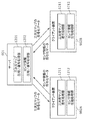
- FIG. 17 is a diagram showing a system configuration in this case.
- the client device 902C issues a sensor information transmission request to the nearby client device 902A, and acquires the sensor information from the client device 902A. Then, the client device 902C creates three-dimensional data using the acquired sensor information of the client device 902A, and updates the three-dimensional map of the client device 902C. As a result, the client device 902C can generate a three-dimensional map of the space that can be acquired from the client device 902A by utilizing the performance of the client device 902C. For example, it is considered that such a case occurs when the performance of the client device 902C is high.
- the client device 902A that provided the sensor information is given the right to acquire the highly accurate three-dimensional map generated by the client device 902C.
- the client device 902A receives a highly accurate 3D map from the client device 902C in accordance with its rights.
- the client device 902C may issue a request for transmitting sensor information to a plurality of nearby client devices 902 (client device 902A and client device 902B).
- client device 902A and client device 902B client devices 902
- the client device 902C can create three-dimensional data using the sensor information obtained by the high-performance sensor.
- FIG. 18 is a block diagram showing the functional configurations of the server 901 and the client device 902.
- the server 901 includes, for example, a three-dimensional map compression / decoding processing unit 1201 that compresses and decodes a three-dimensional map, and a sensor information compression / decoding processing unit 1202 that compresses and decodes sensor information.
- the client device 902 includes a three-dimensional map decoding processing unit 1211 and a sensor information compression processing unit 1212.
- the three-dimensional map decoding processing unit 1211 receives the encoded data of the compressed three-dimensional map, decodes the encoded data, and acquires the three-dimensional map.
- the sensor information compression processing unit 1212 compresses the sensor information itself instead of the three-dimensional data created from the acquired sensor information, and transmits the compressed sensor information encoded data to the server 901.
- the client device 902 may internally hold a processing unit (device or LSI) that performs a process of decoding a three-dimensional map (point cloud, etc.), and the three-dimensional data of the three-dimensional map (point cloud, etc.). It is not necessary to hold a processing unit that performs processing for compressing. As a result, the cost and power consumption of the client device 902 can be suppressed.
- the client device 902 is mounted on the moving body, and is obtained from the sensor information 1033 indicating the surrounding condition of the moving body obtained by the sensor 1015 mounted on the moving body. Create peripheral three-dimensional data 1034.
- the client device 902 estimates the self-position of the moving body using the created three-dimensional data 1034.
- the client device 902 transmits the acquired sensor information 1033 to the server 901 or another mobile body 902.
- the client device 902 transmits the sensor information 1033 to the server 901 and the like.
- the amount of data to be transmitted can be reduced as compared with the case where three-dimensional data is transmitted.
- the processing amount of the client device 902 can be reduced. Therefore, the client device 902 can reduce the amount of data to be transmitted or simplify the configuration of the device.
- the client device 902 further transmits a three-dimensional map transmission request to the server 901, and receives the three-dimensional map 1031 from the server 901. In estimating the self-position, the client device 902 estimates the self-position using the three-dimensional data 1034 and the three-dimensional map 1032.
- the sensor information 1033 includes at least one of the information obtained by the laser sensor, the luminance image, the infrared image, the depth image, the position information of the sensor, and the speed information of the sensor.
- the sensor information 1033 includes information indicating the performance of the sensor.
- the client device 902 encodes or compresses the sensor information 1033, and in transmitting the sensor information, transmits the encoded or compressed sensor information 1037 to the server 901 or another mobile body 902. According to this, the client device 902 can reduce the amount of data to be transmitted.
- the client device 902 includes a processor and a memory, and the processor uses the memory to perform the above processing.
- the server 901 can communicate with the client device 902 mounted on the mobile body, and the sensor information 1037 indicating the surrounding situation of the mobile body obtained by the sensor 1015 mounted on the mobile body is obtained. Is received from the client device 902. The server 901 creates three-dimensional data 1134 around the moving body from the received sensor information 1037.
- the server 901 creates the three-dimensional data 1134 using the sensor information 1037 transmitted from the client device 902. As a result, there is a possibility that the amount of data to be transmitted can be reduced as compared with the case where the client device 902 transmits three-dimensional data. Further, since it is not necessary for the client device 902 to perform processing such as compression or coding of three-dimensional data, the processing amount of the client device 902 can be reduced. Therefore, the server 901 can reduce the amount of data to be transmitted or simplify the configuration of the device.
- the server 901 further transmits a transmission request for sensor information to the client device 902.
- the server 901 updates the three-dimensional map 1135 using the created three-dimensional data 1134, and sends the three-dimensional map 1135 to the client device 902 in response to the transmission request of the three-dimensional map 1135 from the client device 902. Send.
- the sensor information 1037 includes at least one of the information obtained by the laser sensor, the luminance image, the infrared image, the depth image, the position information of the sensor, and the speed information of the sensor.
- the sensor information 1037 includes information indicating the performance of the sensor.
- the server 901 further corrects the three-dimensional data according to the performance of the sensor. According to this, the three-dimensional data creation method can improve the quality of the three-dimensional data.
- the server 901 receives a plurality of sensor information 1037 from the plurality of client devices 902, and based on a plurality of information indicating the performance of the sensor included in the plurality of sensor information 1037, the server 901 receives three-dimensional data 1134.
- the sensor information 1037 used for creating the above is selected. According to this, the server 901 can improve the quality of the three-dimensional data 1134.
- the server 901 decodes or decompresses the received sensor information 1037, and creates three-dimensional data 1134 from the decoded or decompressed sensor information 1132. According to this, the server 901 can reduce the amount of data to be transmitted.
- the server 901 includes a processor and a memory, and the processor uses the memory to perform the above processing.
- FIG. 19 is a diagram showing a configuration of a system according to the present embodiment.
- the system shown in FIG. 19 includes a server 2001, a client device 2002A, and a client device 2002B.
- the client device 2002A and the client device 2002B are mounted on a moving body such as a vehicle, and transmit sensor information to the server 2001.
- the server 2001 transmits a three-dimensional map (point cloud) to the client device 2002A and the client device 2002B.
- the client device 2002A includes a sensor information acquisition unit 2011, a storage unit 2012, and a data transmission availability determination unit 2013.
- the configuration of the client device 2002B is also the same. Further, in the following, when the client device 2002A and the client device 2002B are not particularly distinguished, they are also described as the client device 2002.
- FIG. 20 is a flowchart showing the operation of the client device 2002 according to the present embodiment.
- the sensor information acquisition unit 2011 acquires various sensor information using a sensor (sensor group) mounted on the moving body. That is, the sensor information acquisition unit 2011 acquires sensor information indicating the surrounding condition of the moving body, which is obtained by the sensor (sensor group) mounted on the moving body. Further, the sensor information acquisition unit 2011 stores the acquired sensor information in the storage unit 2012.
- This sensor information includes at least one of LiDAR acquisition information, visible light image, infrared image and depth image. Further, the sensor information may include at least one of sensor position information, speed information, acquisition time information, and acquisition location information.
- the sensor position information indicates the position of the sensor from which the sensor information has been acquired.
- the velocity information indicates the velocity of the moving object when the sensor acquires the sensor information.
- the acquisition time information indicates the time when the sensor information is acquired by the sensor.
- the acquisition location information indicates the position of the moving body or the sensor when the sensor information is acquired by the sensor.
- the data transmission availability determination unit 2013 determines whether the mobile body (client device 2002) exists in an environment in which the sensor information can be transmitted to the server 2001 (S2002). For example, the data transmission availability determination unit 2013 may specify the location and time of the client device 2002 by using information such as GPS, and determine whether or not the data can be transmitted. In addition, the data transmission availability determination unit 2013 may determine whether or not data can be transmitted depending on whether or not it can be connected to a specific access point.
- the client device 2002 determines that the moving body exists in an environment in which the sensor information can be transmitted to the server 2001 (Yes in S2002), the client device 2002 transmits the sensor information to the server 2001 (S2003). That is, when the client device 2002 is in a situation where the sensor information can be transmitted to the server 2001, the client device 2002 transmits the held sensor information to the server 2001.
- a millimeter-wave access point capable of high-speed communication is installed at an intersection or the like.
- the sensor information held by the client device 2002 is transmitted to the server 2001 at high speed by using millimeter wave communication.
- the client device 2002 deletes the sensor information transmitted to the server 2001 from the storage unit 2012 (S2004).
- the client device 2002 may delete the sensor information when the sensor information not transmitted to the server 2001 satisfies a predetermined condition.
- the client device 2002 may delete the sensor information from the storage unit 2012 when the acquisition time of the sensor information to be held is older than a certain time before the current time. That is, the client device 2002 may delete the sensor information from the storage unit 2012 when the difference between the time when the sensor information is acquired by the sensor and the current time exceeds a predetermined time. Further, the client device 2002 may delete the sensor information from the storage unit 2012 when the acquisition location of the sensor information to be held is more than a certain distance from the current position.
- the sensor information May be deleted from the storage unit 2012.
- the capacity of the storage unit 2012 of the client device 2002 can be suppressed.
- the client device 2002 repeats the processes after step S2001.
- the client device 2002 ends the process.
- the client device 2002 may select the sensor information to be transmitted to the server 2001 according to the communication status. For example, when high-speed communication is possible, the client device 2002 preferentially transmits sensor information (for example, LiDAR acquisition information) having a large size held in the storage unit 2012. Further, when high-speed communication is difficult, the client device 2002 transmits sensor information (for example, a visible light image) having a small size and a high priority held in the storage unit 2012. As a result, the client device 2002 can efficiently transmit the sensor information held in the storage unit 2012 to the server 2001 according to the network conditions.
- sensor information for example, LiDAR acquisition information
- sensor information for example, a visible light image
- the client device 2002 may acquire the time information indicating the current time and the location information indicating the current location from the server 2001. Further, the client device 2002 may determine the acquisition time and acquisition location of the sensor information based on the acquired time information and location information. That is, the client device 2002 may acquire the time information from the server 2001 and generate the acquisition time information using the acquired time information. Further, the client device 2002 may acquire the location information from the server 2001 and generate the acquisition location information using the acquired location information.
- the server 2001 and the client device 2002 synchronize the time using a mechanism such as NTP (Network Time Protocol) or PTP (Precision Time Protocol).
- NTP Network Time Protocol
- PTP Precision Time Protocol
- the client device 2002 can acquire accurate time information.
- the server 2001 can handle the sensor information indicating the synchronized time.
- the time synchronization mechanism may be any method other than NTP or PTP.
- GPS information may be used as the time information and location information.
- the server 2001 may acquire sensor information from a plurality of client devices 2002 by designating a time or place. For example, in the event of an accident, the server 2001 broadcasts a sensor information transmission request to a plurality of client devices 2002 by designating the time and place of the accident in order to search for a client in the vicinity thereof. Then, the client device 2002 having the sensor information of the corresponding time and place transmits the sensor information to the server 2001. That is, the client device 2002 receives the sensor information transmission request including the designated information for designating the place and time from the server 2001. The client device 2002 determines that the storage unit 2012 stores the sensor information obtained at the place and time indicated by the designated information, and that the moving body exists in an environment in which the sensor information can be transmitted to the server 2001.
- the sensor information obtained at the place and time indicated by the designated information is transmitted to the server 2001.
- the server 2001 can acquire sensor information related to the occurrence of an accident from a plurality of client devices 2002 and use it for accident analysis and the like.
- the client device 2002 may refuse to transmit the sensor information when it receives the sensor information transmission request from the server 2001. Further, the client device 2002 may set in advance which sensor information among the plurality of sensor information can be transmitted. Alternatively, the server 2001 may inquire of the client device 2002 whether or not the sensor information can be transmitted each time.
- points may be given to the client device 2002 that has transmitted the sensor information to the server 2001. These points can be used to pay, for example, gasoline purchase costs, EV (Electric Vehicle) charging costs, highway tolls, or rental car costs.
- the server 2001 may delete the information for identifying the client device 2002 that is the source of the sensor information. For example, this information is information such as the network address of the client device 2002.
- the sensor information can be anonymized, so that the user of the client device 2002 can safely transmit the sensor information from the client device 2002 to the server 2001.
- the server 2001 may be composed of a plurality of servers. For example, by sharing sensor information among a plurality of servers, even if one server fails, another server can communicate with the client device 2002. As a result, it is possible to avoid stopping the service due to a server failure.
- the designated location specified in the sensor information transmission request indicates the position where the accident occurred, and may differ from the position of the client device 2002 at the designated time specified in the sensor information transmission request. Therefore, the server 2001 can request the client device 2002 existing in the range to acquire information by designating a range such as within XXm in the vicinity as the designated place. Similarly, for the designated time, the server 2001 may specify a range such as within N seconds before and after a certain time. As a result, the server 2001 can acquire the sensor information from the client device 2002 that exists at "time: t-N to t + N, location: within XXm from the absolute position S". When transmitting three-dimensional data such as LiDAR, the client device 2002 may transmit the data generated immediately after the time t.
- three-dimensional data such as LiDAR
- the server 2001 may separately specify, as the designated location, the information indicating the location of the client device 2002 for which the sensor information is to be acquired and the location where the sensor information is desired. For example, the server 2001 specifies that the sensor information including at least the range from the absolute position S to YYm is acquired from the client device 2002 existing within XXm from the absolute position S.
- the client device 2002 selects the 3D data of one or more randomly accessible units so as to include at least the sensor information in the specified range.
- the client device 2002 may transmit a plurality of time-consecutive image data including at least a frame immediately before or after the time t.
- the client device 2002 uses a network to be used according to the priority notified from the server 2001. You may choose. Alternatively, the client device 2002 itself may select a network that can secure an appropriate bandwidth based on the size of the transmitted data. Alternatively, the client device 2002 may select a network to be used based on the cost for data transmission and the like. Further, the transmission request from the server 2001 may include information indicating a transmission deadline, such as transmission when the client device 2002 can start transmission by time T. The server 2001 may issue a transmission request again if sufficient sensor information cannot be acquired within the deadline.
- a transmission deadline such as transmission when the client device 2002 can start transmission by time T.
- the sensor information may include header information indicating the characteristics of the sensor data together with the compressed or uncompressed sensor data.
- the client device 2002 may transmit the header information to the server 2001 via a physical network or communication protocol different from the sensor data. For example, the client device 2002 transmits the header information to the server 2001 prior to the transmission of the sensor data.
- the server 2001 determines whether or not to acquire the sensor data of the client device 2002 based on the analysis result of the header information.
- the header information may include information indicating the point cloud acquisition density, elevation angle, or frame rate of LiDAR, or the resolution, signal-to-noise ratio, or frame rate of a visible light image. As a result, the server 2001 can acquire the sensor information from the client device 2002 having the sensor data of the determined quality.
- the client device 2002 acquires the sensor information indicating the surrounding situation of the moving body, which is mounted on the moving body and obtained by the sensor mounted on the moving body, and stores the sensor information in the storage unit 2012. ..
- the client device 2002 determines whether the moving body exists in an environment capable of transmitting sensor information to the server 2001, and if it determines that the moving body exists in an environment capable of transmitting sensor information to the server, the client device 2002 transmits the sensor information to the server 2001. Send to.
- the client device 2002 further creates three-dimensional data around the moving body from the sensor information, and estimates the self-position of the moving body using the created three-dimensional data.
- the client device 2002 further transmits a three-dimensional map transmission request to the server 2001, and receives the three-dimensional map from the server 2001.
- the client device 2002 estimates the self-position by using the three-dimensional data and the three-dimensional map in the estimation of the self-position.
- processing by the client device 2002 may be realized as an information transmission method in the client device 2002.
- the client device 2002 includes a processor and a memory, and the processor may perform the above processing using the memory.
- FIG. 21 is a diagram showing a configuration of a sensor information collection system according to the present embodiment.
- the sensor information collection system according to the present embodiment includes a terminal 2021A, a terminal 2021B, a communication device 2022A, a communication device 2022B, a network 2023, a data collection server 2024, and a map server 2025.
- the client device 2026 and the like.
- the terminal 2021A and the terminal 2021B are not particularly distinguished, they are also described as the terminal 2021.
- the communication device 2022A and the communication device 2022B are not particularly distinguished, they are also described as the communication device 2022.
- the data collection server 2024 collects data such as sensor data obtained by the sensor included in the terminal 2021 as position-related data associated with the position in the three-dimensional space.
- the sensor data is, for example, data acquired by using a sensor included in the terminal 2021 such as a state around the terminal 2021 or an internal state of the terminal 2021.
- the terminal 2021 transmits sensor data collected from one or more sensor devices at a position capable of directly communicating with the terminal 2021 or relaying one or a plurality of relay devices by the same communication method to the data collection server 2024. Send.
- the data included in the position-related data may include, for example, information indicating the operation status of the terminal itself or the device included in the terminal, the operation log, the usage status of the service, and the like. Further, the data included in the position-related data may include information in which the identifier of the terminal 2021 is associated with the position or movement route of the terminal 2021.
- the information indicating the position included in the position-related data is associated with the information indicating the position in the three-dimensional data such as the three-dimensional map data.
- the details of the information indicating the position will be described later.
- the position-related data includes the above-mentioned time information and the attributes of the data included in the position-related data, or information indicating the type of sensor (for example, model number) that generated the data, in addition to the position information which is the information indicating the position. It may contain at least one of.
- the position information and the time information may be stored in the header area of the position-related data or the header area of the frame for storing the position-related data. Further, the position information and the time information may be transmitted and / or stored separately from the position-related data as metadata associated with the position-related data.
- the map server 2025 is connected to the network 2023, for example, and transmits three-dimensional data such as three-dimensional map data in response to a request from another device such as the terminal 2021. Further, as described in each of the above-described embodiments, the map server 2025 may have a function of updating three-dimensional data by using the sensor information transmitted from the terminal 2021.
- the data collection server 2024 is connected to the network 2023, for example, collects position-related data from another device such as the terminal 2021, and stores the collected position-related data in a storage device inside or in another server. Further, the data collection server 2024 transmits the collected position-related data or the metadata of the three-dimensional map data generated based on the position-related data to the terminal 2021 in response to the request from the terminal 2021.
- Network 2023 is a communication network such as the Internet.
- the terminal 2021 is connected to the network 2023 via the communication device 2022.
- the communication device 2022 communicates with the terminal 2021 while switching between one communication method or a plurality of communication methods.
- the communication device 2022 is, for example, (1) a base station such as LTE (Long Term Evolution), (2) an access point (AP) such as WiFi or millimeter wave communication, and (3) LPWA such as SIGFOX, LoRaWAN or Wi-SUN. (Low Power Wide Area)
- a communication satellite that communicates using a network gateway or (4) a satellite communication method such as DVB-S2.
- the base station may communicate with the terminal 2021 by a method classified into LPWA such as NB-IoT (Narrow Band-IoT) or LTE-M, or may switch between these methods and the terminal 2021. Communication may be performed.
- LPWA Low Band-IoT
- LTE-M Long Term Evolution
- Communication may be performed.
- the terminal 2021 has a function of communicating with a communication device 2022 that uses two types of communication methods, and a communication device that uses any of these communication methods, or is a plurality of these communication methods and a direct communication partner.
- a communication device 2022 that uses two types of communication methods
- a communication device that uses any of these communication methods, or is a plurality of these communication methods and a direct communication partner.
- An example is given in which communication is performed with the map server 2025 or the data collection server 2024 while switching 2022, but the configuration of the sensor information collection system and the terminal 2021 is not limited to this.
- the terminal 2021 may not have a communication function in a plurality of communication methods, but may have a function of communicating in any one communication method.
- the terminal 2021 may support three or more communication methods. Further, the corresponding communication method may be different for each terminal 2021.
- the terminal 2021 includes, for example, the configuration of the client device 902 shown in FIG.
- the terminal 2021 estimates the position such as its own position using the received three-dimensional data. Further, the terminal 2021 generates position-related data by associating the sensor data acquired from the sensor with the position information obtained by the position estimation process.
- the position information added to the position-related data indicates, for example, the position in the coordinate system used in the three-dimensional data.
- the position information is a coordinate value represented by a value of latitude and longitude.
- the terminal 2021 may include the coordinate value as well as the information indicating the coordinate system that is the reference of the coordinate value and the three-dimensional data used for the position estimation in the position information.
- the coordinate values may include altitude information.
- the position information may be associated with a unit of data or a unit of space that can be used for coding the three-dimensional data described above.
- This unit is, for example, WLD, GOS, SPC, VLM, VXL, or the like.
- the position information is represented by an identifier for specifying a data unit such as an SPC corresponding to the position-related data.
- the position information is information indicating three-dimensional data in which the three-dimensional space including the data unit such as SPC is encoded, or details in the SPC. It may include information indicating a different position.
- the information indicating the three-dimensional data is, for example, a file name of the three-dimensional data.
- the system generates the position-related data associated with the position information based on the position estimation using the three-dimensional data, so that the self-position of the client device (terminal 2021) acquired by using GPS is set. It is possible to add position information to the sensor information with higher accuracy than when the based position information is added to the sensor information. As a result, even when the position-related data is used by another device in another service, the position corresponding to the position-related data can be more accurately specified in the real space by performing the position estimation based on the same three-dimensional data. There is a possibility that it can be done.
- the data transmitted from the terminal 2021 is the position-related data
- the data transmitted from the terminal 2021 may be data not associated with the position information.
- the transmission / reception of the three-dimensional data or the sensor data described in the other embodiment may be performed via the network 2023 described in the present embodiment.
- the position information added to the position-related data may be information indicating a position relative to a feature point in the three-dimensional data.
- the feature point that serves as a reference for the position information is, for example, a feature point encoded as SWLD and notified to the terminal 2021 as three-dimensional data.
- the information indicating the relative position with respect to the feature point is represented by, for example, a vector from the feature point to the point indicated by the position information, and may be information indicating the direction and distance from the feature point to the point indicated by the position information.
- the information indicating the relative position with respect to the feature point may be information indicating the amount of displacement of each of the X-axis, Y-axis, and Z-axis from the feature point to the point indicated by the position information.
- the information indicating the relative position with respect to the feature point may be information indicating the distance from each of the three or more feature points to the point indicated by the position information.
- the relative position may not be the relative position of the point indicated by the position information expressed with respect to each feature point, but may be the relative position of each feature point expressed with reference to the point indicated by the position information.
- An example of position information based on a relative position with respect to a feature point includes information for specifying a reference feature point and information indicating a relative position of a point indicated by the position information with respect to the feature point.
- the information indicating the relative position with respect to the feature point includes the coordinate axes used for deriving the relative position and the information indicating the type of the three-dimensional data. Alternatively, it may include information indicating the magnitude (scale, etc.) of the value of the information indicating the relative position per unit amount.
- the position information may include information indicating a relative position with respect to each feature point for a plurality of feature points.
- the terminal 2021 that tries to specify the position indicated by the position information in the real space has the position information from the position of the feature point estimated from the sensor data for each feature point.
- the candidate points of the positions indicated by may be calculated, and the points obtained by averaging the calculated plurality of candidate points may be determined to be the points indicated by the position information. According to this configuration, the influence of an error when estimating the position of a feature point from the sensor data can be reduced, so that the estimation accuracy of the point indicated by the position information in the real space can be improved.
- the position information includes information indicating a relative position with respect to a plurality of feature points, even if there is a feature point that cannot be detected due to restrictions such as the type or performance of the sensor included in the terminal 2021, any of the plurality of feature points. If even one of them can be detected, the value of the point indicated by the position information can be estimated.
- a point that can be identified from the sensor data can be used.
- the points that can be identified from the sensor data are, for example, points within a region or points that satisfy predetermined conditions for feature point detection, such as the above-mentioned three-dimensional feature amount or feature amount of visible light data being equal to or greater than a threshold value.
- a marker installed in the real space may be used as a feature point.
- the marker may be detected and its position can be specified from the data acquired by using a sensor such as LiDER or a camera.
- the marker is represented by a change in color or brightness value (reflectance), or a three-dimensional shape (unevenness, etc.).
- a coordinate value indicating the position of the marker, a two-dimensional code or a barcode generated from the identifier of the marker, or the like may be used.
- a light source that transmits an optical signal may be used as a marker.
- a light source of an optical signal is used as a marker, not only information for acquiring a position such as a coordinate value or an identifier but also other data may be transmitted by the optical signal.
- the optical signal is connected to the content of the service according to the position of the marker, an address such as a url for acquiring the content, or an identifier of the wireless communication device for receiving the provision of the service, and the wireless communication device. It may include information indicating a wireless communication method for the purpose.
- the terminal 2021 grasps the correspondence relationship of feature points between different data by using, for example, an identifier commonly used between data or information or a table indicating the correspondence relationship of feature points between data. Further, when there is no information indicating the correspondence between the feature points, the terminal 2021 is the feature at the closest distance when the coordinates of the feature points in one three-dimensional data are converted to the positions in the other three-dimensional data space. A point may be determined to be a corresponding feature point.
- the position information based on the relative position described above is used, even between terminals 2021 or services that use different three-dimensional data, they are included in each three-dimensional data or associated with each three-dimensional data.
- the position indicated by the position information can be specified or estimated based on a common feature point. As a result, it becomes possible to identify or estimate the same position with higher accuracy between terminals 2021 or services that use different three-dimensional data.
- the data collection server 2024 may transfer the received position-related data to another data server.
- the data collection server 2024 determines to which data server the received position-related data is to be transferred, and transfers the position-related data to the data server determined as the transfer destination.
- the data collection server 2024 determines the transfer destination based on, for example, the determination rule of the transfer destination server preset in the data collection server 2024.
- the determination rule of the transfer destination server is set, for example, in a transfer destination table in which the identifier associated with each terminal 2021 and the data server of the transfer destination are associated with each other.
- the terminal 2021 adds an identifier associated with the terminal 2021 to the position-related data to be transmitted and transmits the data to the data collection server 2024.
- the data collection server 2024 specifies the data server of the transfer destination corresponding to the identifier added to the position-related data based on the determination rule of the transfer destination server using the transfer destination table or the like, and the position-related data is specified. Send to the data server. Further, the determination rule of the transfer destination server may be specified by the determination condition using the time or place where the position-related data is acquired.
- the identifier associated with the transmission source terminal 2021 described above is, for example, an identifier unique to each terminal 2021 or an identifier indicating a group to which the terminal 2021 belongs.
- the transfer destination table does not have to be a direct association between the identifier associated with the source terminal and the transfer destination data server.
- the data collection server 2024 holds a management table that stores tag information assigned to each identifier unique to the terminal 2021, and a transfer destination table that associates the tag information with the data server of the transfer destination.
- the data collection server 2024 may determine the data server of the transfer destination based on the tag information by using the management table and the transfer destination table.
- the tag information is, for example, management control information or service provision control information given to the type, model number, owner, group to which the terminal 2021 corresponds to the identifier, or other identifier.
- an identifier unique to each sensor may be used instead of the identifier associated with the transmission source terminal 2021.
- the determination rule of the transfer destination server may be set from the client device 2026.
- the data collection server 2024 may determine a plurality of data servers as transfer destinations and transfer the received position-related data to the plurality of data servers. According to this configuration, for example, when backing up location-related data automatically, or in order to share location-related data with different services, location-related data is sent to a data server for providing each service. When it is necessary to do so, the data can be transferred as intended by changing the setting for the data collection server 2024. As a result, the man-hours required for constructing and changing the system can be reduced as compared with the case where the transmission destination of the position-related data is set in the individual terminals 2021.
- the data collection server 2024 registers the data server specified by the transfer request signal as a new transfer destination in response to the transfer request signal received from the data server, and transfers the position-related data received thereafter to the data server. You may.
- the data collection server 2024 stores the position-related data received from the terminal 2021 in the recording device, and requests the position-related data specified by the transmission request signal according to the transmission request signal received from the terminal 2021 or the data server. It may be transmitted to the terminal 2021 or the data server of.
- the data collection server 2024 determines whether or not the location-related data can be provided to the requesting data server or terminal 2021, and if it is determined that the location-related data can be provided, the data collection server 2024 transfers or transmits the location-related data to the requesting data server or terminal 2021. May be done.
- the data collection server 2024 When the request for the current position-related data is received from the client device 2026, the data collection server 2024 requests the terminal 2021 to transmit the position-related data even if the terminal 2021 does not transmit the position-related data. 2021 may transmit position-related data in response to the transmission request.
- the terminal 2021 transmits the position information data to the data collection server 2024, but the data collection server 2024 collects the position-related data from the terminal 2021, such as a function of managing the terminal 2021. It may be provided with a function necessary for the terminal 2021 or a function used when collecting position-related data from the terminal 2021.
- the data collection server 2024 may have a function of transmitting a data request signal requesting the transmission of position information data to the terminal 2021 and collecting position-related data.
- Management information such as an address for communicating with the terminal 2021 to be collected data or an identifier unique to the terminal 2021 is registered in the data collection server 2024 in advance.
- the data collection server 2024 collects location-related data from the terminal 2021 based on the registered management information.
- the management information may include information such as the type of sensor included in the terminal 2021, the number of sensors included in the terminal 2021, and the communication method supported by the terminal 2021.
- the data collection server 2024 may collect information such as the operating status or the current position of the terminal 2021 from the terminal 2021.
- the registration of the management information may be performed from the client device 2026, or the process for registration may be started by the terminal 2021 transmitting the registration request to the data collection server 2024.
- the data collection server 2024 may have a function of controlling communication with the terminal 2021.
- the communication connecting the data collection server 2024 and the terminal 2021 is a dedicated line provided by a service provider such as an MNO (Mobile Network Operator) or a MVNO (Mobile Virtual Network Operator), or a VPN (Virtual Private Network) configured Network. It may be a virtual private line or the like. According to this configuration, communication between the terminal 2021 and the data collection server 2024 can be performed safely.
- a service provider such as an MNO (Mobile Network Operator) or a MVNO (Mobile Virtual Network Operator), or a VPN (Virtual Private Network) configured Network. It may be a virtual private line or the like. According to this configuration, communication between the terminal 2021 and the data collection server 2024 can be performed safely.
- the data collection server 2024 may have a function of authenticating the terminal 2021 or a function of encrypting data transmitted to and received from the terminal 2021.
- the authentication process of the terminal 2021 or the data encryption process is a terminal group including an identifier unique to the terminal 2021 or a plurality of terminals 2021 shared in advance between the data collection server 2024 and the terminal 2021. It is done by using a unique identifier for.
- This identifier is, for example, an IMSI (International Mobile Subscribe Subsiber Identity), which is a unique number stored in a SIM (Subscriber Identity Module) card.
- IMSI International Mobile Subscribe Subsiber Identity
- SIM Subscriber Identity Module
- the process of authentication or data encryption between the data collection server 2024 and the terminal 2021 can be provided as long as both the data collection server 2024 and the terminal 2021 have a function to perform the process, and relays the data. It does not depend on the communication method used by the communication device 2022. Therefore, since the common authentication or encryption process can be used without considering whether the terminal 2021 uses the communication method, the convenience of the user's system construction is improved. However, the fact that the communication device 2022 for relaying does not depend on the communication method means that it is not essential to change the communication method according to the communication method. That is, for the purpose of improving transmission efficiency or ensuring safety, the authentication or data encryption process between the data collection server 2024 and the terminal 2021 may be switched according to the communication method used by the relay device.
- the data collection server 2024 may provide the client device 2026 with a UI that manages data collection rules such as the type of location-related data collected from the terminal 2021 and the data collection schedule. As a result, the user can specify the terminal 2021 for collecting data using the client device 2026, the data collection time and frequency, and the like. Further, the data collection server 2024 may specify an area on the map on which data is to be collected and collect position-related data from the terminal 2021 included in the area.
- the client device 2026 When the data collection rule is managed in units of terminals 2021, the client device 2026 presents, for example, a list of terminals 2021 or sensors to be managed on the screen. The user sets the necessity of data collection or the collection schedule for each item in the list.
- the client device 2026 When designating an area on a map for which data is to be collected, the client device 2026 presents, for example, a two-dimensional or three-dimensional map of the area to be managed on the screen. The user selects an area on the displayed map to collect data.
- the area selected on the map may be a circular or rectangular area centered on a point specified on the map, or may be a circular or rectangular area that can be specified by a drag operation.
- the client device 2026 may also select an area in preset units such as a city, an area within the city, a block, or a major road.
- the area may be set by inputting the numerical values of latitude and longitude, or the area is selected from the list of candidate areas derived based on the input text information. May be done.
- Textual information may be, for example, the name of a region, city, or landmark.
- an area on the map may be specified based on the position of the client device 2026 in the real space obtained from the sensor data. For example, the client device 2026 estimates its own position using sensor data, and data a region within a predetermined distance from a point on the map corresponding to the estimated position or a distance specified by the user. May be specified as the area to collect. Further, the client device 2026 may designate the sensing area of the sensor, that is, the area corresponding to the acquired sensor data as the area for collecting the data. Alternatively, the client device 2026 may designate an area based on the position corresponding to the sensor data specified by the user as an area for collecting data. The area or position on the map corresponding to the sensor data may be estimated by the client device 2026 or the data collection server 2024.
- the data collection server 2024 When specifying in the area on the map, the data collection server 2024 identifies the terminal 2021 in the specified area by collecting the current position information of each terminal 2021, and positions the terminal 2021 with respect to the specified terminal 2021. You may request the transmission of relevant data. Further, the data collection server 2024 does not specify the terminal 2021 in the area, but the data collection server 2024 transmits information indicating the designated area to the terminal 2021, and the terminal 2021 itself is in the designated area. Whether or not it is determined, and if it is determined that it is within the specified area, the position-related data may be transmitted.
- the data collection server 2024 transmits data such as a list or a map for providing the above-mentioned UI (User Interface) in the application executed by the client device 2026 to the client device 2026.
- the data collection server 2024 may transmit not only data such as a list or a map but also an application program to the client device 2026.
- the above-mentioned UI may be provided as content created by HTML or the like that can be displayed by a browser.
- Some data such as map data may be provided from a server other than the data collection server 2024 such as the map server 2025.
- the client device 2026 transmits the input information to the data collection server 2024 as the setting information when the input for notifying the completion of the input is performed such as the user pressing the setting button.
- the data collection server 2024 transmits a signal for notifying the position-related data request or the position-related data collection rule to each terminal 2021 based on the setting information received from the client device 2026, and collects the position-related data. Do.
- object information indicating the position of a power feeding unit such as a wireless power feeding antenna or a power feeding coil embedded in a road or a parking lot is included in the three-dimensional data or associated with the three-dimensional data.
- a power feeding unit such as a wireless power feeding antenna or a power feeding coil embedded in a road or a parking lot is included in the three-dimensional data or associated with the three-dimensional data.
- terminal 2021 such as a car or drone.
- the vehicle or drone that has acquired the object information for charging automatically drives itself so that the position of the charging part such as the charging antenna or charging coil of the vehicle faces the area indicated by the object information. Move the position of and start charging.
- the direction to move or the operation to be performed is presented to the driver or operator using the image or sound displayed on the screen.
- the operation or maneuvering is stopped.
- the image or sound presented to is switched, and charging is started.
- the object information may not be information indicating the position of the power feeding unit, but may be information indicating an area where charging efficiency equal to or higher than a predetermined threshold value can be obtained by arranging the charging unit in the area.
- the position of the object information may be represented by a point at the center of the region indicated by the object information, a region or line in a two-dimensional plane, or a region, line or plane in a three-dimensional space. Good.
- the antenna for wireless charging provided in the terminal 2021 such as a car and the wireless embedded in the road or the like can be grasped.
- the alignment with the feeding antenna can be performed with higher accuracy. As a result, the charging speed at the time of wireless charging can be shortened and the charging efficiency can be improved.
- the object information may be an object other than the feeding antenna.
- the three-dimensional data includes the position of the AP of millimeter-wave wireless communication as object information.
- the terminal 2021 can grasp the position of the AP in advance, so that the directivity of the beam can be directed in the direction of the object information and the communication can be started.
- the communication quality such as improving the transmission speed, shortening the time until the start of communication, and extending the communicable period.
- the object information may include information indicating the type of the object corresponding to the object information. Further, the object information should be executed by the terminal 2021 when the terminal 2021 is included in the area in the real space corresponding to the position of the object information on the three-dimensional data or within a range of a predetermined distance from the area. Information indicating the process may be included.
- the object information may be provided by a server different from the server that provides the three-dimensional data.
- the object group in which the object information used in the same service is stored may be provided as different data depending on the type of the target service or the target device. ..
- the three-dimensional data used in combination with the object information may be WLD point cloud data or SWLD feature point data.
- FIG. 22 is a diagram showing a structural example of a volume including a plurality of voxels.
- FIG. 23 is a diagram showing an example in which the volume shown in FIG. 22 is converted into an ocree tree structure.
- the leaves 1, 2 and 3 represent the voxels VXL1, VXL2 and VXL3 shown in FIG. 22, respectively, and represent the VXL including the point cloud (hereinafter, effective VXL).
- the ocree is represented by, for example, a binary sequence of 0 and 1.
- the binary sequence shown in FIG. 23 is assigned to each node and leaf.
- this binary string is scanned according to the breadth-first or depth-first scan order. For example, when breadth-first scan is performed, the binary sequence shown in A in FIG. 24 is obtained. When scanning with priority on depth, the binary sequence shown in B of FIG. 24 is obtained.
- the binary sequence obtained by this scan is encoded by entropy coding to reduce the amount of information.
- the depth in the ocree representation is used to control the granularity of the point cloud information contained in the volume. If the depth is set large, the point cloud information can be reproduced to a finer level, but the amount of data for expressing the node and leaf increases. Conversely, if the depth is set small, the amount of data will decrease, but since multiple point cloud information with different positions and colors are considered to be at the same position and with the same color, the information that the original point cloud information has will be lost. become.
- FIG. 25 is a diagram showing an example in which the ocree with a depth of 2 shown in FIG. 23 is represented by an ocree with a depth of 1.
- the ocree shown in FIG. 25 has a smaller amount of data than the ocree shown in FIG. 23. That is, the ocree shown in FIG. 25 has a smaller number of bits after binarization than the ocree shown in FIG. 25.
- the leaf 1 and the leaf 2 shown in FIG. 23 are represented by the leaf 1 shown in FIG. 24. That is, the information that the leaf 1 and the leaf 2 shown in FIG. 23 are at different positions is lost.
- FIG. 26 is a diagram showing a volume corresponding to the ocree shown in FIG. 25.
- VXL1 and VXL2 shown in FIG. 22 correspond to VXL12 shown in FIG. 26.
- the three-dimensional data coding apparatus generates the color information of VXL12 shown in FIG. 26 from the color information of VXL1 and VXL2 shown in FIG.
- the three-dimensional data encoding device calculates the average value, the intermediate value, the weight average value, and the like of the color information of VXL1 and VXL2 as the color information of VXL12. In this way, the three-dimensional data coding device may control the reduction of the amount of data by changing the depth of the ocree.
- the three-dimensional data encoding device may set the depth information of the octave tree in any unit of world unit, space unit, and volume unit. At that time, the three-dimensional data encoding device may add depth information to the world header information, the space header information, or the volume header information. In addition, the same value may be used for depth information for all worlds, spaces, and volumes at different times. In this case, the three-dimensional data coding device may add depth information to the header information that manages the world for the entire time.
- FIG. 27 is a diagram for explaining the coding of attribute information using RAHT.
- the three-dimensional data encoding device generates a Morton code based on the position information of the three-dimensional points, and sorts the attribute information of the three-dimensional points in the order of the Morton codes. For example, the three-dimensional data coding device may sort in ascending order of Morton code. The sort order is not limited to the Morton code order, and other orders may be used.
- the three-dimensional data encoding device generates a high-frequency component and a low-frequency component of the layer L by applying the Har transformation to the attribute information of two three-dimensional points adjacent to each other in the Morton code order.
- the three-dimensional data coding device may use the Har transformation of a 2 ⁇ 2 matrix.
- the generated high-frequency component is included in the coding coefficient as the high-frequency component of the layer L, and the generated low-frequency component is used as an input value of the upper layer L + 1 of the layer L.
- the three-dimensional data coding device generates the high-frequency component of the layer L using the attribute information of the layer L, and then continues to process the layer L + 1.
- the three-dimensional data coding device In the processing of the layer L + 1, the three-dimensional data coding device generates the high frequency component and the low frequency component of the layer L + 1 by applying the Har conversion to the two low frequency components obtained by the Haar conversion of the attribute information of the layer L. To do.
- the generated high-frequency component is included in the coding coefficient as the high-frequency component of the layer L + 1, and the generated low-frequency component is used as the input value of the upper layer L + 2 of the layer L + 1.
- the three-dimensional data coding device repeats such hierarchical processing, and determines that the highest layer Lmax has been reached when the number of low-frequency components input to the layer becomes one.
- the three-dimensional data coding apparatus includes the low frequency component of the layer Lmax-1 input to the layer Lmax in the coding coefficient. Then, the value of the low frequency component or the high frequency component included in the coding coefficient is quantized and coded by using entropy coding or the like.
- the 3D data encoding device sets the value of the attribute information of the existing 3D point in the upper layer. It may be used as an input value.
- the three-dimensional data coding device hierarchically applies the Har transformation to the input attribute information, generates high-frequency components and low-frequency components of the attribute information, and applies quantization and the like described later. And encode. Thereby, the coding efficiency can be improved.
- the three-dimensional data coding device may independently apply the Har conversion for each dimension and calculate each coding coefficient.
- the attribute information is color information (RGB, YUV, etc.)
- the three-dimensional data coding apparatus applies Har conversion for each component and calculates the coding coefficient for each component.
- the three-dimensional data coding apparatus may apply the Har conversion in the order of layer L, L + 1, ..., Layer Lmax. The closer to the layer Lmax, the more the coding coefficient including the low frequency component of the input attribute information is generated.
- W0 and w1 shown in FIG. 27 are weights assigned to each three-dimensional point.
- the three-dimensional data coding apparatus may calculate the weight based on the distance information between two adjacent three-dimensional points to which the Har transformation is applied.
- the three-dimensional data coding apparatus may improve the coding efficiency by increasing the weight as the distance becomes shorter.
- the three-dimensional data coding apparatus may calculate this weight by another method, or may not use the weight.
- the input attribute information is a0, a1, a2, a3, a4 and a5. Further, among the coding coefficients after the Har conversion, Ta1, Ta5, Tb1, Tb3, Tc1 and d0 are coded. Other coding coefficients (b0, b2, c0, etc.) are intermediate values and are not coded.
- the high frequency component Ta1 and the low frequency component b0 are generated by performing the Har conversion between a0 and a1.
- the low frequency component b0 is the average value of a0 and a1
- the high frequency component Ta1 is the difference between a0 and a1.
- a2 Since there is no paired attribute information in a2, a2 is used as it is as b1. Similarly, since there is no paired attribute information in a3, a3 is used as it is as b2. Further, by performing the Har conversion between a4 and a5, a high frequency component Ta5 and a low frequency component b3 are generated.
- the high frequency component Tb1 and the low frequency component c0 are generated by performing the Har conversion between b0 and b1. Similarly, by performing the Har conversion between b2 and b3, the high frequency component Tb3 and the low frequency component c1 are generated.
- the high frequency component Tc1 and the low frequency component d0 are generated by performing the Har conversion between c0 and c1.
- the three-dimensional data coding apparatus may encode after quantizing the coding coefficient after applying the Har conversion.
- a three-dimensional data coding apparatus performs quantization by dividing a coding coefficient by a quantization scale (also referred to as a quantization step (QS (Quantization Step))).
- QS quantization Step
- the smaller the quantization scale the smaller the error (quantization error) that can occur due to quantization.
- the larger the quantization scale the larger the quantization error.
- FIG. 28 is a diagram showing an example of setting the quantization scale for each layer.
- the higher layer has a smaller quantization scale
- the lower layer has a larger quantization scale. Since the coding coefficient of the three-dimensional point belonging to the upper layer contains more low-frequency components than the lower layer, it is highly possible that it is an important component in human visual characteristics and the like. Therefore, by reducing the quantization scale of the upper layer and suppressing the quantization error that may occur in the upper layer, visual deterioration can be suppressed and the coding efficiency can be improved.
- the three-dimensional data coding device may add a quantization scale for each layer to the header or the like. As a result, the three-dimensional data decoding device can correctly decode the quantization scale and appropriately decode the bit stream.
- the three-dimensional data coding apparatus may adaptively switch the value of the quantization scale according to the importance of the target three-dimensional point to be encoded. For example, a 3D data coding device uses a small quantization scale for 3D points of high importance and a large quantization scale for 3D points of low importance. For example, the three-dimensional data coding apparatus may calculate the importance from the weights at the time of Har conversion and the like. For example, the three-dimensional data coding apparatus may calculate the quantization scale using the added values of w0 and w1. By reducing the quantization scale of the three-dimensional points, which are of high importance in this way, the quantization error can be reduced and the coding efficiency can be improved.
- the higher the layer the smaller the QS value may be.
- the QW value becomes larger in the upper layer, and the prediction efficiency can be improved by suppressing the quantization error of the three-dimensional point.
- the coding coefficient Ta1q after the quantization of the coding coefficient Ta1 of the attribute information a1 is represented by Ta1 / QS_L.
- the QS may have the same value in all layers or some layers.
- QW Quality Weight
- the QW is a value indicating the importance of a three-dimensional point to be encoded.
- the QW the above-mentioned added value of w0 and w1 may be used.
- the QW value becomes larger in the upper layer, and the prediction efficiency can be improved by suppressing the quantization error of the three-dimensional point.
- the 3D data coding device may first initialize the QW values of all 3D points with 1, and update the QW of each 3D point using the values of w0 and w1 at the time of Har conversion. Good.
- the three-dimensional data coding apparatus may change the initial values according to the hierarchy without initializing the QWs of all the three-dimensional points with the value 1. For example, by setting a larger initial value of QW in the upper layer, the quantization scale of the upper layer becomes smaller. As a result, the prediction error of the upper layer can be suppressed, so that the prediction accuracy of the lower layer can be improved and the coding efficiency can be improved.
- the three-dimensional data coding device does not necessarily have to use QW.
- the three-dimensional data coding device scans and encodes the coding coefficient (unsigned integer value) after quantization in a certain order.
- the three-dimensional data coding apparatus encodes a plurality of three-dimensional points in order from the three-dimensional points included in the upper layer toward the lower layer.
- the three-dimensional data coding device encodes a plurality of three-dimensional points in the order of Tc1q, Tb1q, Tb3q, Ta1q, and Ta5q from d0q included in the upper layer Lmax.
- the lower layer L tends to have a coding coefficient of 0 after quantization. The reasons for this include the following.
- the coding coefficient of the lower layer L shows a higher frequency component than that of the upper layer, it tends to be 0 depending on the target three-dimensional point. Further, by switching the quantization scale according to the importance and the like described above, the quantization scale becomes larger in the lower layer, and the coding coefficient after quantization tends to be 0.
- FIG. 29 is a diagram showing an example of a first code string and a second code string.
- the three-dimensional data encoding device counts the number of times the value 0 occurs in the first code string, and encodes the number of times the value 0 occurs consecutively instead of the continuous value 0. That is, the three-dimensional data coding apparatus generates the second code string by replacing the coding coefficient of the continuous value 0 in the first code string with the number of consecutive times of 0 (ZeroCnt).
- ZeroCnt the number of consecutive times of 0
- the three-dimensional data coding device may entropy-encode the value of ZeroCnt. For example, a three-dimensional data encoding device binarizes the value of ZeroCnt with a truncated unary code of the total number of encoded three-dimensional points T, and arithmetically encodes each bit after binarization. ..
- FIG. 30 is a diagram showing an example of a truncet unity code when the total number of coded three-dimensional points is T. At this time, the three-dimensional data coding apparatus may improve the coding efficiency by using a different coding table for each bit.
- the three-dimensional data coding apparatus uses the coding table 1 for the first bit, the coding table 2 for the second bit, and the coding table 3 for the subsequent bits. As described above, the three-dimensional data coding apparatus can improve the coding efficiency by switching the coding table for each bit.
- the three-dimensional data encoding device may binarize ZeroCnt with an exponential-Golomb and then perform arithmetic coding. As a result, when the value of ZeroCnt tends to be large, the efficiency can be improved as compared with the binarization arithmetic coding by the truncet unity code.
- the three-dimensional data coding device may add a flag to the header for switching between using the truncet unity code and using the exponential Golomb code. As a result, the three-dimensional data coding apparatus can improve the coding efficiency by selecting the optimum binarization method.
- the three-dimensional data decoding device can correctly decode the bit stream by switching the binarization method with reference to the flag included in the header.
- the 3D data decoding device may convert the decoded quantization coefficient from the unsigned integer value to the signed integer value by the method opposite to the method performed by the 3D data coding device.
- the 3D data decoding device can appropriately decode the generated bit stream without considering the generation of negative integers.
- the three-dimensional data decoding device does not necessarily have to convert the coding coefficient from an unsigned integer value to a signed integer value. For example, when the three-dimensional data decoding device decodes a bit stream including a separately entropy-coded coded bit, the code bit may be decoded.
- the three-dimensional data decoding device decodes the coding coefficient after quantization converted into a signed integer value by inverse quantization and inverse Har conversion. Further, the three-dimensional data decoding device uses the decoding coefficient after decoding for the prediction after the three-dimensional point to be decoded. Specifically, the three-dimensional data decoding device calculates the inverse quantization value by multiplying the coding coefficient after quantization by the decoded quantization scale. Next, the three-dimensional data decoding device obtains the decoded value by applying the inverse Haar transformation described later to the inverse quantized value.
- the three-dimensional data decoding device converts the decoded unsigned integer value into a signed integer value by the following method.
- the signed integer value Ta1q is set to ⁇ ((a2u + 1) >> 1).
- the signed integer value Ta1q is set to (a2u >> 1).
- Ta1q is a quantized value of Ta1.
- QS_L is a quantization step of the layer L.
- the QS may have the same value in all layers or some layers.
- the three-dimensional data coding apparatus may add information indicating QS to the header or the like. As a result, the three-dimensional data decoding device can correctly perform inverse quantization using the same QS as the QS used in the three-dimensional data coding device.
- FIG. 31 is a diagram for explaining the inverse Har transformation.
- the three-dimensional data decoding apparatus decodes the attribute value of the three-dimensional point by applying the inverse Haar transformation to the coding coefficient after the inverse quantization.
- the three-dimensional data decoding device generates a Morton code based on the position information of the three-dimensional point, and sorts the three-dimensional points in the order of the Morton code. For example, the three-dimensional data decoding device may sort in ascending order of Morton code. The sort order is not limited to the Morton code order, and other orders may be used.
- the three-dimensional data decoding device applies the inverse Har transformation to the coding coefficient including the low frequency component of the layer L + 1 and the coding coefficient including the high frequency component of the layer L, so that the three-dimensional data decoding device is adjacent in the Morton code order in the layer L.
- the three-dimensional data decoding device may use an inverse Har transformation of a 2 ⁇ 2 matrix.
- the restored attribute information of the layer L is used as an input value of the lower layer L-1.
- the three-dimensional data decoding device repeats such hierarchical processing, and ends the processing when all the attribute information of the lowest layer is decoded.
- the three-dimensional data decoding device has an attribute value of one existing three-dimensional point.
- the value of the coding component of the layer L may be substituted for.
- the three-dimensional data decoding device can correctly decode the bit stream with improved coding efficiency by applying the Har conversion to all the values of the input attribute information.
- the three-dimensional data decoding device may independently apply the inverse Har conversion for each dimension and decode each coding coefficient. For example, when the attribute information is color information (RGB, YUV, etc.), the three-dimensional data decoding device applies an inverse Har conversion to the coding coefficient for each component and decodes each attribute value.
- the attribute information is color information (RGB, YUV, etc.)
- the three-dimensional data decoding device applies an inverse Har conversion to the coding coefficient for each component and decodes each attribute value.
- the three-dimensional data decoding device may apply the inverse Har transformation in the order of layer Lmax, L + 1, ..., Layer L. Further, w0 and w1 shown in FIG. 31 are weights assigned to each three-dimensional point. For example, the three-dimensional data decoding device may calculate the weight based on the distance information between two adjacent three-dimensional points to which the inverse Haar transformation is applied. For example, the three-dimensional data coding apparatus may decode a bit stream whose coding efficiency is improved by increasing the weight as the distance becomes shorter.
- the coding coefficients after dequantization are Ta1, Ta5, Tb1, Tb3, Tc1 and d0, and a0, a1, a2, a3, a4 and a5 are obtained as decoding values.
- FIG. 32 is a diagram showing an example of syntax of attribute information (attribute_data).
- the attribute information (attribute_data) includes a zero continuous number (ZeroCnt), an attribute dimension number (attribute_dimension), and a coding coefficient (value [j] [i]).
- Zero continuous number indicates the number of consecutive values of 0 in the coding coefficient after quantization.
- the three-dimensional data coding device may binarize ZeroCnt and then perform arithmetic coding.
- the three-dimensional data coding apparatus determines whether or not the layer L (layerL) to which the coding coefficient belongs is equal to or higher than a predetermined threshold value TH_layer, and adds the coding coefficient to the bit stream according to the determination result. You may switch the information. For example, the three-dimensional data coding device adds all the coding coefficients of the attribute information to the bit stream if the determination result is true. Further, the three-dimensional data coding apparatus may add a part of the coding coefficient to the bit stream if the determination result is false.
- the three-dimensional data encoding device adds the coding result of the RGB or YUV three-dimensional information of the color information to the bit stream. If the determination result is false, the three-dimensional data encoding device does not need to add some information such as G or Y of the color information to the bitstream and other components to the bitstream. Good. In this way, the three-dimensional data coding device does not add a part of the coding coefficient of the layer (layer smaller than TH_layer) including the coding coefficient indicating the high frequency component whose deterioration is less noticeable visually to the bit stream. , The coding efficiency can be improved.
- the number of dimension dimensions of the attribute indicates the number of dimensions of the attribute information. For example, when the attribute information is the color information of a three-dimensional point (RGB, YUV, etc.), the number of attribute dimensions is set to the value 3 because the color information is three-dimensional. When the attribute information is the reflectance, the number of attribute dimensions is set to the value 1 because the reflectance is one-dimensional. The number of attribute dimensions may be added to the header of the attribute information of the bitstream.
- the coding coefficient indicates the coding coefficient after the quantization of the j-th dimension attribute information of the i-th three-dimensional point. For example, when the attribute information is color information, value [99] [1] indicates the coding coefficient of the second dimension (for example, G value) of the 100th three-dimensional point. When the attribute information is reflectance information, value [119] [0] indicates the coding coefficient of the first dimension (for example, reflectance) of the 120th three-dimensional point.
- the three-dimensional data coding apparatus may subtract the value 1 from the value [j] [i] and entropy-code the obtained value.
- the three-dimensional data decoding apparatus restores the coding coefficient by adding the value 1 to the value [j] [i] after the entropy decoding.
- attribute_dimension 1, or (2) when attribute_dimension is 1 or more and the values of all dimensions are equal.
- attribute_dimension 1, so the three-dimensional data coding device calculates the value by subtracting the value 1 from the coding coefficient, and encodes the calculated value.
- the three-dimensional data decoding device adds the value 1 to the decoded value to calculate the coding coefficient.
- the three-dimensional data coding apparatus encodes a value 9 obtained by subtracting the value 1 from the coding coefficient value 10.
- the three-dimensional data decoding device adds the value 1 to the decoded value 9 to calculate the value 10 of the coding coefficient.
- attribute_dimension 3 so that the three-dimensional data coding device can be used for each coding, for example, when the coding coefficients after the quantization of each component of R, G, and B are the same.
- the value 1 is subtracted from the coefficient and the resulting value is encoded.
- the three-dimensional data decoding device adds 1 to each component of (0, 0, 0) to calculate (1, 1, 1).
- the three-dimensional data coding device encodes (2, 1, 2) as it is.
- the three-dimensional data decoding device uses the decoded (2, 1, 2) as it is as the coding coefficient.
- value [0] [i] shown in FIG. 32 indicates the coding coefficient after the quantization of the first-dimensional attribute information of the i-th three-dimensional point.
- the layer L (layerL) to which the coding coefficient belongs is smaller than the threshold TH_layer, the first-dimensional attribute information is added to the bitstream (the second-dimensional and subsequent attribute information is not added to the bitstream).
- the code amount may be reduced with.
- FIG. 33 is a diagram showing an example of the coding coefficient and ZeroCnt in this case.
- the three-dimensional data encoding device counts a number of consecutive coding coefficients in which the R, G, and B components are all 0, and the counted number is set as ZeroCnt in a bit stream. Add. As a result, it is not necessary to encode ZeroCnt for each component, and the overhead can be reduced. Therefore, the coding efficiency can be improved.
- the three-dimensional data coding apparatus may calculate ZeroCnt for each dimension even when attribute_dimension is 2 or more, and add the calculated ZeroCnt to the bit stream.
- FIG. 34 is a flowchart of the three-dimensional data coding process according to the present embodiment.
- the three-dimensional data coding device encodes the position information (geometry) (S6601).
- a three-dimensional data coding device encodes using an octree representation.
- the three-dimensional data coding device converts the attribute information (S6602). For example, a three-dimensional data coding device reassigns the attribute information of the original three-dimensional point to the changed three-dimensional point when the position of the three-dimensional point changes due to quantization or the like after coding the position information. To do.
- the three-dimensional data coding device may interpolate the value of the attribute information according to the amount of change in the position and reassign it. For example, the three-dimensional data encoding device detects N three-dimensional points before the change, which are close to the three-dimensional position after the change, and obtains the attribute information values of the N three-dimensional points from the three-dimensional position after the change.
- Weighted averaging is performed based on the distances to each N 3Ds, and the obtained values are set as the values of the attribute information of the changed 3D points. Further, in the three-dimensional data encoding device, when two or more three-dimensional points are changed to the same three-dimensional position due to quantization or the like, the value of the attribute information after the change is two or more before the change. The average value of the attribute information at the three-dimensional point may be assigned.
- the three-dimensional data coding device encodes the attribute information (S6603). For example, when encoding a plurality of attribute information, the three-dimensional data encoding device may encode the plurality of attribute information in order. For example, when the color and the reflectance are encoded, the three-dimensional data encoding device generates a bit stream in which the reflectance coding result is added after the color coding result as the attribute information. The plurality of coding results of the attribute information added to the bit stream may be in any order.
- the three-dimensional data encoding device may add information indicating the start location of the encoded data of each attribute information in the bit stream to the header or the like.
- the three-dimensional data decoding device can selectively decode the attribute information that needs to be decoded, so that the decoding process of the attribute information that does not need to be decoded can be omitted. Therefore, the processing amount of the three-dimensional data decoding device can be reduced.
- the three-dimensional data coding apparatus may encode a plurality of attribute information in parallel and integrate the coding result into one bit stream. As a result, the three-dimensional data coding device can encode a plurality of attribute information at high speed.
- FIG. 35 is a flowchart of the attribute information coding process (S6603).
- the three-dimensional data coding apparatus generates a coding coefficient from the attribute information by Har conversion (S6611).
- the three-dimensional data coding device applies quantization to the coding coefficient (S6612).
- the three-dimensional data coding apparatus generates coding attribute information (bit stream) by coding the coding coefficient after quantization (S6613).
- the three-dimensional data coding device applies inverse quantization to the coding coefficient after quantization (S6614).
- the three-dimensional data decoding apparatus decodes the attribute information by applying the inverse Har transformation to the coding coefficient after the inverse quantization (S6615). For example, the decoded attribute information is referenced in subsequent coding.
- FIG. 36 is a flowchart of the coding coefficient coding process (S6613).
- the three-dimensional data coding apparatus converts the coding coefficient from a signed integer value to an unsigned integer value (S6621).
- a three-dimensional data coding device converts a signed integer value into an unsigned integer value as follows. If the signed integer value Ta1q is less than 0, the unsigned integer value is set to -1- (2 x Ta1q). When the signed integer value Ta1q is 0 or more, the unsigned integer value is set to 2 ⁇ Ta1q. If the coding coefficient does not become a negative value, the three-dimensional data coding device may encode the coding coefficient as it is as an unsigned integer value.
- the three-dimensional data coding device determines whether the value of the coding coefficient to be processed is zero (S6623). When the value of the coding coefficient to be processed is zero (Yes in S6623), the three-dimensional data coding device increments ZeroCnt by 1 (S6624) and returns to step S6622.
- the three-dimensional data coding device When the value of the coding coefficient to be processed is not zero (No in S6623), the three-dimensional data coding device encodes ZeroCnt and resets ZeroCnt to 0 (S6625). Further, the three-dimensional data coding apparatus arithmetically encodes the coding coefficient to be processed (S6626), and returns to step S6622. For example, a three-dimensional data coding device performs binary arithmetic coding. Further, the three-dimensional data coding apparatus may subtract the value 1 from the coding coefficient and encode the obtained value.
- steps S6623 to S6626 are repeated for each coding coefficient. Further, when all the coding coefficients have been processed (Yes in S6622), the three-dimensional data coding apparatus ends the processing.
- FIG. 37 is a flowchart of the three-dimensional data decoding process according to the present embodiment.
- the three-dimensional data decoding device decodes the position information (geometry) from the bit stream (S6631). For example, a three-dimensional data decoding device decodes using an ocree representation.
- the three-dimensional data decoding device decodes the attribute information from the bit stream (S6632). For example, when decoding a plurality of attribute information, the three-dimensional data decoding device may decode the plurality of attribute information in order. For example, when decoding a color and a reflectance as attribute information, the three-dimensional data decoding apparatus decodes the color coding result and the reflectance coding result in the order of being added to the bit stream. For example, in a bitstream, if the color coding result is followed by the reflectance coding result, the 3D data decoder decodes the color coding result and then the reflectance coding. Decrypt the result. The three-dimensional data decoding device may decode the coding result of the attribute information added to the bit stream in any order.
- the three-dimensional data decoding device may acquire information indicating the start location of the encoded data of each attribute information in the bit stream by decoding the header or the like.
- the three-dimensional data decoding device can selectively decode the attribute information that needs to be decoded, so that the decoding process of the attribute information that does not need to be decoded can be omitted. Therefore, the processing amount of the three-dimensional data decoding device can be reduced.
- the three-dimensional data decoding device may decode a plurality of attribute information in parallel and integrate the decoding results into one three-dimensional point cloud. As a result, the three-dimensional data decoding device can decode a plurality of attribute information at high speed.
- FIG. 38 is a flowchart of the attribute information decoding process (S6632).
- the three-dimensional data decoding device decodes the coding coefficient from the bit stream (S6641).
- the three-dimensional data decoding device applies inverse quantization to the coding coefficient (S6642).
- the three-dimensional data decoding apparatus decodes the attribute information by applying the inverse Har transformation to the coding coefficient after the inverse quantization (S6643).
- FIG. 39 is a flowchart of the coding coefficient decoding process (S6641).
- the three-dimensional data decoding device decodes ZeroCnt from the bit stream (S6651). If all the coding coefficients have not been processed (No in S6652), the 3D data decoding device determines whether ZeroCnt is greater than 0 (S6653).
- the three-dimensional data decoding device sets the coding coefficient of the processing target to 0 (S6654). Next, the three-dimensional data decoding device subtracts 1 from ZeroCnt (S6655) and returns to step S6652.
- the three-dimensional data decoding device decodes the coding coefficient of the processing target (S6656). For example, a three-dimensional data decoding device uses binary arithmetic decoding. Further, the three-dimensional data decoding device may add a value 1 to the decoded coding coefficient.
- the three-dimensional data decoding device decodes ZeroCnt, sets the obtained value in ZeroCnt (S6657), and returns to step S6652.
- the processes of steps S6653 to S6657 are repeated for each coding coefficient. Further, when all the coding coefficients have been processed (Yes in S6652), the three-dimensional data coding apparatus converts the plurality of decoded coding coefficients from an unsigned integer value to a signed integer value (S6658). ..
- the three-dimensional data decoding apparatus may convert the decoded coding coefficient from an unsigned integer value to a signed integer value as described below.
- the LSB least significant bit
- the signed integer value Ta1q is set to ⁇ ((Ta1u + 1) >> 1).
- the three-dimensional data decoding device may use the decoded coding coefficient as it is as a signed integer value.
- FIG. 40 is a block diagram of the attribute information coding unit 6600 included in the three-dimensional data coding device.
- the attribute information coding unit 6600 includes a sorting unit 6601, a Har conversion unit 6602, a quantization unit 6603, an inverse quantization unit 6604, an inverse Haar conversion unit 6605, a memory 6606, and an arithmetic coding unit 6607. Be prepared.
- the sort unit 6601 generates a Morton code using the position information of the three-dimensional points, and sorts a plurality of three-dimensional points in the order of the Morton code.
- the Har conversion unit 6602 generates a coding coefficient by applying the Har conversion to the attribute information.
- the quantization unit 6603 quantizes the coding coefficient of the attribute information.
- the dequantization unit 6604 dequantizes the coding coefficient after quantization.
- the inverse Har conversion unit 6605 applies the inverse Har conversion to the coding coefficient.
- the memory 6606 stores the values of the attribute information of the plurality of decoded three-dimensional points. For example, the attribute information of the decoded three-dimensional point stored in the memory 6606 may be used for the prediction of the unencoded three-dimensional point and the like.
- the arithmetic coding unit 6607 calculates ZeroCnt from the coding coefficient after quantization, and arithmetically encodes ZeroCnt. In addition, the arithmetic coding unit 6607 arithmetically encodes the non-zero coding coefficient after quantization. The arithmetic coding unit 6607 may binarize the coding coefficient before arithmetic coding. Further, the arithmetic coding unit 6607 may generate and encode various header information.
- FIG. 41 is a block diagram of the attribute information decoding unit 6610 included in the three-dimensional data decoding device.
- the attribute information decoding unit 6610 includes an arithmetic decoding unit 6611, an inverse quantization unit 6612, an inverse Har conversion unit 6613, and a memory 6614.
- the arithmetic decoding unit 6611 arithmetically decodes ZeroCnt and the coding coefficient included in the bit stream.
- the arithmetic decoding unit 6611 may decode various header information.
- the dequantization unit 6612 dequantizes the arithmetically decoded coding coefficient.
- the inverse Har conversion unit 6613 applies the inverse Har transformation to the coding coefficient after the inverse quantization.
- the memory 6614 stores the values of the attribute information of the plurality of decoded three-dimensional points. For example, the attribute information of the decoded three-dimensional point stored in the memory 6614 may be used for predicting the undecoded three-dimensional point.
- the coding order is not necessarily limited to this.
- a method of scanning the coding coefficient after the Har conversion in the order of the upper layer to the lower layer may be used.
- the three-dimensional data coding apparatus may encode the number of consecutive values of 0 as ZeroCnt.
- the three-dimensional data coding apparatus may switch whether or not to use the coding method using ZeroCnt described in the present embodiment for each WLD, SPC, or volume.
- the three-dimensional data coding apparatus may add information indicating whether or not the coding method using ZeroCnt is applied to the header information.
- the three-dimensional data decoding device can appropriately perform decoding.
- a three-dimensional data coding device counts the number of occurrences of a coding coefficient having a value of 0 for one volume.
- the three-dimensional data coding device applies the method using ZeroCnt to the next volume when the count value exceeds a predetermined threshold value, and uses ZeroCnt to the next volume when the count value is equal to or less than the threshold value. Do not apply the method that was used. As a result, the three-dimensional data coding apparatus can appropriately switch whether or not to apply the coding method using ZeroCnt according to the characteristics of the three-dimensional point to be coded, thus improving the coding efficiency. it can.
- the three-dimensional data coding apparatus scans and encodes the coding coefficient (unsigned integer value) after quantization in a certain order.
- the three-dimensional data coding apparatus encodes a plurality of three-dimensional points in order from the three-dimensional points included in the lower layer toward the upper layer.
- FIG. 42 is a diagram showing an example of a first code string and a second code string when this method is used for the attribute information shown in FIG. 27.
- the three-dimensional data coding apparatus encodes a plurality of coding coefficients in the order of Ta1q to Ta5q, Tb1q, Tb3q, Tc1q, d0q included in the lower layer L.
- the lower the layer the more likely the coding coefficient after quantization tends to be zero. The reasons for this include the following.
- the coding coefficient of the lower layer L shows a higher frequency component than that of the upper layer, it tends to be 0 depending on the three-dimensional point to be coded. Further, by switching the quantization scale according to the importance and the like described above, the quantization scale becomes larger in the lower layer, and the coding coefficient after quantization tends to be 0.
- the three-dimensional data coding apparatus counts the number of times the value 0 occurs in the first code string, and encodes the number of times the value 0 occurs consecutively (ZeroCnt) instead of the continuous value 0.
- ZeroCnt the number of times the value 0 occurs consecutively
- the three-dimensional data coding device may encode information indicating the total number of occurrences of the value 0. As a result, the overhead of coding ZeroCnt can be reduced, and the coding efficiency can be improved.
- the three-dimensional data coding device encodes the total number of coding coefficients having a value of 0 as TotalZeroCnt.
- the three-dimensional data coding device may entropy-encode TotalZeroCnt. For example, the three-dimensional data encoding device binarizes the value of TotalZeroCnt with a truncet unity code of the total number T of the coded three-dimensional points, and arithmetically encodes each bit after binarization.
- the three-dimensional data coding apparatus may improve the coding efficiency by using a different coding table for each bit. For example, the three-dimensional data coding apparatus uses the coding table 1 for the first bit, the coding table 2 for the second bit, and the coding table 3 for the subsequent bits. In this way, the three-dimensional data coding apparatus can improve the coding efficiency by switching the coding table for each bit.
- the three-dimensional data coding device may perform arithmetic coding after binarizing TotalZeroCnt with an exponential Golomb.
- the three-dimensional data coding device may add a flag to the header for switching between using the truncet unity code and using the exponential Golomb code.
- the three-dimensional data coding apparatus can improve the coding efficiency by selecting the optimum binarization method.
- the three-dimensional data decoding device can correctly decode the bit stream by switching the binarization method with reference to the flag included in the header.
- FIG. 43 is a diagram showing a syntax example of attribute information (attribute_data) in this modified example.
- the attribute information (attribute_data) shown in FIG. 43 further includes a total number of zeros (TotalZeroCnt) with respect to the attribute information shown in FIG. 32.
- TotalZeroCnt indicates the total number of coding coefficients with a value of 0 after quantization.
- FIG. 44 is a diagram showing an example of the coding coefficient, ZeroCnt and TotalZeroCnt in this case. For example, in the case of the color information shown in FIG. 44, the three-dimensional data coding apparatus counts the number of consecutive coding coefficients in which the R, G, and B components are all 0, and the counted numbers are bit as TotalZeroCnt and ZeroCnt. Add to the stream.
- the three-dimensional data coding apparatus may calculate TotalZeoCnt and ZeroCnt for each dimension even when attribute_dimension is 2 or more, and add the calculated TotalZeoCnt and ZeroCnt to the bit stream.
- FIG. 45 is a flowchart of the coding coefficient coding process (S6613) in this modification.
- the three-dimensional data coding apparatus converts the coding coefficient from a signed integer value to an unsigned integer value (S6661).
- the three-dimensional data coding device encodes TotalZeroCnt (S6662).
- the three-dimensional data coding apparatus determines whether the value of the coding coefficient to be processed is zero (S6664). When the value of the coding coefficient to be processed is zero (Yes in S6664), the three-dimensional data coding device increments ZeroCnt by 1 (S6665) and returns to step S6663.
- the three-dimensional data coding device determines whether TotalZeroCnt is larger than 0 (S6666). If TotalZeroCnt is greater than 0 (Yes in S6666), the 3D data encoder encodes ZeroCnt and sets TotalZeroCnt to TotalZeroCnt-ZeroCnt (S6667).
- step S6667 or when TotalZeroCnt is 0 (No in S6666), the 3D data encoding device encodes the coding coefficient, resets ZeroCnt to 0 (S6666), and returns to step S6663.
- a three-dimensional data coding device performs binary arithmetic coding. Further, the three-dimensional data coding apparatus may subtract the value 1 from the coding coefficient and encode the obtained value.
- steps S6664 to S6668 are repeated for each coding coefficient. Further, when all the coding coefficients have been processed (Yes in S6663), the three-dimensional data coding apparatus ends the processing.
- FIG. 46 is a flowchart of the coding coefficient decoding process (S6641) in this modification.
- the three-dimensional data decoding device decodes TotalZeroCnt from the bit stream (S6671).
- the three-dimensional data decoding device decodes ZeroCnt from the bit stream and sets TotalZeroCnt to TotalZeroCnt-ZeroCnt (S6672).
- the three-dimensional data coding device determines whether ZeroCnt is greater than 0 (S6674).
- the three-dimensional data decoding device sets the coding coefficient of the processing target to 0 (S6675). Next, the three-dimensional data decoding device subtracts 1 from ZeroCnt (S6676) and returns to step S6673.
- the three-dimensional data decoding apparatus decodes the coding coefficient of the processing target (S6677). For example, a three-dimensional data decoding device uses binary arithmetic decoding. Further, the three-dimensional data decoding device may add a value 1 to the decoded coding coefficient.
- the three-dimensional data decoding device determines whether TotalZeroCnt is greater than 0 (S6678). If TotalZeroCnt is greater than 0 (Yes in S6678), the 3D data decoder decodes ZeroCnt, sets the resulting value to ZeroCnt, sets TotalZeroCnt to TotalZeroCnt-ZeroCnt (S6679), and returns to step S6673. .. When TotalZeroCnt is 0 (No in S6678), the three-dimensional data decoding device returns to step S6673.
- steps S6674 to S6679 are repeated for each coding coefficient. If all the coding coefficients have been processed (Yes in S6673), the three-dimensional data coding apparatus converts the decoded coding coefficients from an unsigned integer value to a signed integer value (S6680).
- FIG. 47 is a diagram showing another syntax example of the attribute information (attribute_data).
- the attribute information (attribute_data) shown in FIG. 47 includes value [j] [i] _creater_zero_flag and value [j] [i] _greator_one_flag instead of the coding coefficients (value [j] [i]) shown in FIG. 32. , Value [j] [i] and the like. Other information is the same as in FIG. 32.
- Value [j] [i] _greeter_zero_flag indicates whether or not the value of the coding coefficient (value [j] [i]) is greater than 0 (or 1 or more). In other words, value [j] [i] _greeter_zero_flag indicates whether or not the value of the coding coefficient (value [j] [i]) is 0.
- the three-dimensional data coding apparatus does not have to add value [j] [i] to the bitstream when the value of value [j] [i] _greator_zero_flag is 0. In this case, the three-dimensional data decoding device may determine that the values of value [j] and [i] are 0. As a result, the amount of code can be reduced.
- Value [j] [i] _greeter_one_flag indicates whether or not the value of the coding coefficient (value [j] [i]) is greater than 1 (or 2 or more). In other words, value [j] [i] _greeter_one_flag indicates whether or not the value of the coding coefficient (value [j] [i]) is 1.
- value [j] [i] _creater_one_flag is set to the value 1. Otherwise (when the value of the coding coefficient is 1 or less), value [j] [i] _creater_one_flag is set to a value of 0.
- the three-dimensional data coding apparatus does not have to add value [j] [i] to the bit stream.
- the three-dimensional data decoding device may determine that the three-dimensional data coding device has a value of value [j] [i] of 1.
- Value [j] [i] indicates the coding coefficient after the quantization of the j-th dimension attribute information of the i-th three-dimensional point.
- value [99] [1] indicates the coding coefficient of the second dimension (for example, G value) of the 100th three-dimensional point.
- value [119] [0] indicates the coding coefficient of the first dimension (for example, reflectance) of the 120th three-dimensional point.
- the three-dimensional data coding device may entropy-code the value [j] [i] _greator_zero_flag and the value [j] [i] _greeter_one_flag.
- binary arithmetic coding and binary arithmetic decoding may be used. As a result, the coding efficiency can be improved.
- the attribute information included in the PCC (Point Cloud Compression) data is converted by using a plurality of methods such as Lifting, RAHT (Region Adaptive Hierarchical Transfer) or other conversion methods.
- Lifting is one of the conversion methods using LoD (Level of Detail).
- the amount of code can be reduced by quantizing the high frequency component. That is, the conversion process has strong energy compression characteristics.
- lossless compression is required to retain the original information while reducing the number of bits.
- Existing transformations such as lifting or RAHT cannot achieve lossless compression because the transformation includes division and square root operators.
- uncomplicated integer-integer conversion is required.
- FIG. 48 is a diagram showing a configuration of a three-dimensional data coding device.
- the three-dimensional data coding apparatus includes an integer conversion unit 8301 and an entropy coding unit 8302.
- the integer conversion unit 8301 generates a coefficient value by converting the input point cloud data into an integer.
- the entropy encoding unit 8302 generates a bit stream by entropy encoding the coefficient value.
- FIG. 49 is a diagram showing a configuration of a three-dimensional data decoding device.
- the three-dimensional data decoding device includes an entropy decoding unit 8303 and an inverse integer conversion unit 8304.
- the entropy decoding unit 8303 obtains a coefficient value by decoding the bit stream.
- the inverse integer conversion unit 8304 generates output point cloud data by converting the coefficient value into an inverse integer.
- FIG. 50 is a diagram for explaining RAHT.
- m-th low-frequency component L l layer l, m and high-frequency component H l, m is represented by two low-frequency components of the layer l + 1 C l + 1,2m and C l + 1,2m + 1 by the following equation (O1) To. That is, the low frequency components L l and m are represented by (Equation O2), and the high frequency components H l and m are represented by (Equation O3).
- the high frequency component is encoded by quantization and entropy coding.
- the low frequency component is used in the next layer as shown in (Equation O4).
- the coefficients ⁇ and ⁇ are updated each time the layer goes up.
- the coefficients ⁇ and ⁇ are represented by (Equation O5) and (Equation O6).
- the weights w l and m are represented by (Equation O7).
- RAHT processing includes the square root operator and division. That is, in RAHT, lossless compression cannot be realized because information is lost. On the other hand, integer-integer conversion can achieve lossless compression.
- FIG. 51 is a diagram for explaining an integer-integer conversion.
- a fixed value is used as the coefficient in RAHT.
- the denormalized Har transformation shown in the following (Equation O8) is used. That is, the low frequency components L l and m are represented by (Equation O9), and the high frequency components H l and m are represented by (Equation O10).
- the high frequency component is encoded by quantization and entropy coding.
- the low frequency component is used in the next layer as shown in (Equation O11).
- the integer Har conversion is realized by (Equation O14) and (Equation O15), and the inverse integer Har conversion is realized by (Equation O16) and (Equation O17).
- is a floor function.
- is included in both (Equation O15) and (Equation O16), the loss caused by this
- Ci and j are defined as integers, Hi, j and Li, j are also integers.
- FIG. 52 is a diagram for explaining a hierarchical conversion process.
- Har transformation When applying the Har transformation to an image, a pair of data is needed to perform the transformation suitable for the pixel transformation.
- an integer Har is applied when a 3D point pair that is a pair of point clouds can be formed, and when a 3D point pair cannot be used, the 3D point pair Data is moved to the next level. Then, this process is performed recursively.
- FIG. 53 is a block diagram of the three-dimensional data coding device 8310.
- the three-dimensional data coding device 8310 generates coded data (coded stream) by encoding point cloud data (point cloud).
- the three-dimensional data coding device 8310 includes a position information coding unit 8311, a lossless attribute information coding unit 8312, an additional information coding unit 8313, and a multiplexing unit 8314.
- the position information coding unit 8311 generates coded position information by encoding the position information.
- the position information coding unit 8311 encodes the position information by using an N-branch structure such as an octa-tree. Specifically, in the octave tree, the target space is divided into eight nodes (subspaces), and 8-bit information (occupancy code) indicating whether or not each node contains a point cloud is generated. .. Further, the node including the point cloud is further divided into eight nodes, and 8-bit information indicating whether or not the point cloud is included in each of the eight nodes is generated. This process is repeated until it becomes equal to or less than the threshold value of the number of point clouds included in the predetermined hierarchy or node.
- the lossless attribute information coding unit 8312 generates the coded attribute information which is the coded data by encoding the attribute information using the configuration information generated by the position information coding unit 8311.
- the additional information coding unit 8313 generates the encoded additional information by encoding the additional information included in the point cloud data.
- the multiplexing unit 8314 generates coded data (coded stream) by multiplexing the coded position information, the coded attribute information, and the coded additional information, and sends out the generated coded data.
- the coded additional information is used at the time of decoding.
- FIG. 54 is a block diagram of the lossless attribute information coding unit 8312.
- the lossless attribute information coding unit 8312 includes an integer conversion unit 8321 and an entropy coding unit 8322.
- the integer conversion unit 8321 generates a coefficient value by performing an integer conversion (for example, an integer Har conversion) on the attribute information.
- the entropy coding unit 8322 generates coding attribute information by entropy-coding the coefficient value.
- FIG. 55 is a block diagram of the integer conversion unit 8321.
- the integer conversion unit 8321 includes a sorting unit 8323 and an integer Har conversion unit 8324.
- the sorting unit 8323 sorts the attribute information based on the position information. For example, the sorting unit 8323 sorts the attribute information in Morton order.
- the integer Haar conversion unit 8324 generates a coefficient value by performing an integer Haar conversion on the sorted attribute information.
- FIG. 56 is a block diagram showing the configuration of the three-dimensional data decoding device 8330.
- the three-dimensional data decoding device 8330 restores the point cloud data by decoding the coded data (encoded stream) generated by encoding the point cloud data.
- the three-dimensional data decoding device 8330 includes a demultiplexing unit 8331, a plurality of position information decoding units 8332, a plurality of lossless attribute information decoding units 8333, and an additional information decoding unit 8334.
- the demultiplexing unit 8331 generates coded position information, coded attribute information, and coded additional information by demultiplexing the coded data (coded stream).
- the position information decoding unit 8332 generates position information by decoding the coded position information.
- the lossless attribute information decoding unit 8333 generates the attribute information by decoding the coded attribute information.
- the lossless attribute information decoding unit 8333 generates the attribute information by performing an inverse integer conversion (for example, an inverse integer Har conversion) on the coded attribute information.
- the additional information decoding unit 8334 generates additional information by decoding the coded additional information.
- FIG. 57 is a block diagram of the lossless attribute information decoding unit 8333.
- the lossless attribute information decoding unit 8333 includes an entropy decoding unit 8341 and an inverse integer conversion unit 8342.
- the entropy decoding unit 8341 generates a coefficient value by entropy decoding the coding attribute information.
- the inverse integer conversion unit 8342 generates attribute information by performing inverse integer conversion (for example, inverse integer Har conversion) on the coefficient value.
- FIG. 58 is a block diagram of the inverse integer conversion unit 8342.
- the inverse integer conversion unit 8342 includes a sorting unit 8343 and an inverse integer Har conversion unit 8344.
- the sorting unit 8343 sorts the coefficient values based on the position information. For example, the sorting unit 8343 sorts the coefficient values in Morton order.
- the inverse integer Har conversion unit 8344 generates attribute information by performing an inverse integer Har conversion on the rearranged coefficient values.
- the information indicating whether the code is coded by lossless coding or irreversible coding is not necessarily limited to this, and for example, the value of the quantization parameter QP or the quantization step Qstep may be used.
- the bitstream is encoded by reversible coding. Therefore, it may be determined that the inverse integer Har conversion is applied to decode the reversibly encoded bit stream.
- Inverse RAHT may be applied to decode the irreversibly coded bitstream.
- FIG. 59 is a flowchart of the lossless attribute information coding process.
- the three-dimensional data coding device rearranges the attribute information of the three-dimensional point cloud (S8301). For example, the three-dimensional data coding device sorts the attribute information of the three-dimensional point cloud in Morton order.
- the three-dimensional data encoding device selects a target point to be processed from the three-dimensional point cloud (S8302). Specifically, the three-dimensional data coding device selects the first three-dimensional point in the three-dimensional point cloud sorted in Morton order.
- the three-dimensional data encoding device determines whether or not there is a three-dimensional point pair (Point Pair), which is a three-dimensional point located next to the target three-dimensional point in Morton order (S8303).
- the 3D data encoding device generates a coefficient value including a high frequency component and a low frequency component by performing an integer Har conversion using the 3D point pair. (S8305).
- the three-dimensional data coding apparatus encodes the generated high-frequency component (for example, entropy-coding) and stores the encoded high-frequency component in the bit stream (S8306). Further, the three-dimensional data coding apparatus stores the low frequency component in a memory or the like for processing in the next layer (S8307).
- the 3D data encoding device stores the attribute information of the target 3D point in the memory or the like for the next layer (S8307).
- the 3D data encoder sets the next 3D point as the target 3D point in Morton order. It is selected (S8302), and the processing after step S8303 is performed on the selected target three-dimensional point.
- the next three-dimensional point in Morton order is the next three-dimensional point of the three-dimensional point pair when the three-dimensional point pair exists, and the target three-dimensional point when the three-dimensional point pair does not exist. It is the next three-dimensional point after the original point.
- the three-dimensional data encoding device starts processing in the next layer (one layer above) (S8309). Further, when the original target layer is not the last layer (top layer) (No in S8310), the three-dimensional data coding device selects the first three-dimensional point in the Morton order in the next layer as the target three-dimensional point. (S8302), the processing after step S8303 is performed on the selected target three-dimensional point.
- the three-dimensional data coding device encodes the low frequency component generated in the last layer (top layer) (for example, entropy coding). Then, the encoded low frequency component is stored in the bit stream (S8311).
- the coding attribute information including the coded high frequency component for each three-dimensional point pair included in each layer and the coded low frequency component of the uppermost layer is generated.
- FIG. 60 is a flowchart of the lossless attribute information decoding process.
- the three-dimensional data decoding device decodes the coefficient value from the bit stream (S8321).
- This coefficient value includes a high-frequency component for each three-dimensional point pair included in each layer and a low-frequency component in the uppermost layer.
- the three-dimensional data decoding device rearranges the obtained coefficient values (S8322). For example, a three-dimensional data decoding device sorts a plurality of high frequency components in Morton order.
- the three-dimensional data decoding apparatus acquires the low-frequency component of the three-dimensional point pair to be processed and the high-frequency component of the processing target and the high-frequency component of the processing target (S8323 and S8324).
- the low-frequency component to be processed is a low-frequency component decoded from the bit stream in the uppermost layer, and is a low-frequency component obtained by the inverse conversion process in the upper layer one layer other than the uppermost layer. is there.
- the high-frequency components to be processed are sorted in Morton order in the uppermost layer and are the first high-frequency components among the high-frequency components. When the three-dimensional point pair does not exist, the high frequency component to be processed does not exist.
- the three-dimensional data decoding device has a three-dimensional point pair (Yes in S8325), that is, when a high-frequency component to be processed exists, the three-dimensional data decoding device has a low-frequency component to be processed and a low-frequency component to be processed.
- the low frequency component of the next lower layer is generated (S8326).
- the attribute information is generated by the inverse integer Har conversion.
- the three-dimensional data decoding device stores the generated low-frequency component in a memory or the like for processing in the next layer (S8327).
- the three-dimensional data decoding device stores the low-frequency component to be processed in a memory or the like for the next layer (S8327).
- the three-dimensional data decoding device processes the next three-dimensional point pair in Morton order in the three-dimensional processing target. It is selected as a point, and the processing of step S8323 and subsequent steps is performed on the selected three-dimensional point pair.
- the three-dimensional data decoding device starts processing in the next layer (one layer below) (S8329). Further, when the original target layer is not the last layer (bottom layer) (No in S8330), the three-dimensional data decoding device processes the first three-dimensional point pair in the Morton order in the next layer as the three-dimensional point pair to be processed. Is selected as, and the processing after step S8323 is performed on the selected three-dimensional point pair.
- the three-dimensional data decoding device ends the process when the original target layer is the last layer (Yes in S8330).
- the attribute information of all three-dimensional points can be obtained.
- FIG. 61 is a diagram showing a configuration example of the integer Har conversion unit 8324.
- the integer Har conversion unit 8324 includes a subtraction unit 8351, a right shift unit 8352, and an addition unit 8353.
- C 1 and C 2 are the attribute information of the three-dimensional point pair in the lowermost layer, respectively, and are the low-frequency components of the three-dimensional point pair obtained in the next lower layer other than the lowest layer.
- H is a high frequency component of a three-dimensional point pair
- L is a low frequency component of a three-dimensional point pair.
- FIG. 62 is a diagram showing a configuration example of the inverse integer Har conversion unit 8344.
- the inverse integer Har conversion unit 8344 includes a right shift unit 8354, a subtraction unit 8355, and an addition unit 8356. With the configuration of the figure, the operations shown in (Equation O20) and (Equation O21) are realized.
- the input data may be divided into a plurality of data of a predetermined unit, and the divided data may be processed in parallel. As a result, the processing can be speeded up.
- FIG. 63 is a diagram showing a configuration of a three-dimensional data coding device in this case.
- the three-dimensional data coding apparatus selectively performs lossless coding (lossless compression) and lossy coding (lossy compression).
- the three-dimensional data coding device may indicate the coding mode by a flag or QP.
- the three-dimensional data coding device shown in FIG. 63 includes a sorting unit 8361, a switching unit 8362, a RAHT unit 8363, a quantization unit 8364, an integer conversion unit 8365, and an entropy coding unit 8366.
- the sorting unit 8361 sorts the attribute information based on the position information in, for example, Morton order.
- the switching unit 8362 outputs the sorted attribute information to the RAHT unit 8363 or the integer conversion unit 8365.
- the switching unit 8362 switches between using RAHT and integer Haar conversion based on LOSSLESS_FLAG.
- LOSSLESS_FLAG is a flag indicating whether to use RAHT (irreversible coding) or integer Haar conversion (lossless coding), and when LOSSLESS_FLAG is on (for example, value 1), integer Haar conversion (lossless). Coded) is used, and RAHT (irreversible coding) is used when LOSSLESS_FLAG is off (eg, value 0).
- the three-dimensional data coding apparatus may determine lossless coding when the value of the quantization parameter QP is a certain value ⁇ .
- switching between RAHT and integer Har conversion is not limited to the LOSSLESS_FLAG or QP value, and may be performed by any method.
- RAHT unit 8363 generates a coefficient value by applying RAHT to the attribute information.
- the quantization coefficient is generated by quantizing the quantization unit 8364.
- the integer conversion unit 8365 generates a coefficient value by applying an integer Har conversion to the attribute information.
- the entropy coding unit 8366 generates coding attribute information by entropy-coding the quantization value generated by the quantization unit 8364 or the coefficient value generated by the integer conversion unit 8365.
- FIG. 64 is a diagram showing a configuration of a three-dimensional data decoding device corresponding to the three-dimensional data coding device shown in FIG. 63.
- the three-dimensional data decoding device shown in FIG. 64 includes an entropy decoding unit 8371, a sorting unit 8372, a switching unit 8373, an inverse quantization unit 8374, an inverse RAHT unit 8375, and an inverse integer conversion unit 8376.
- the entropy decoding unit 8371 generates a coefficient value (or quantization coefficient) by entropy decoding the coding attribute information.
- the sorting unit 8372 sorts the coefficient values based on the position information in, for example, Morton order.
- the switching unit 8373 outputs the rearranged coefficient values to the inverse quantization unit 8374 or the inverse integer conversion unit 8376. For example, the switching unit 8373 switches whether to use RAHT or integer Har conversion based on LOSSLESS_FLAG.
- the method of switching to the switching unit 8373 is the same as the switching method of the switching unit 8362 described above.
- the three-dimensional data decoding device acquires the LOSSLESS_FLAG, the QP value, or the Enable_Integrar_Haar_Transform flag from the bitstream.
- the dequantization unit 8374 generates a coefficient value by dequantizing the quantization coefficient.
- the inverse RAHT unit 8375 generates attribute information by applying the inverse RAHT to the coefficient value.
- the inverse integer conversion unit 8376 generates attribute information by applying the inverse integer Har conversion to the coefficient value.
- FIG. 65 is a diagram showing a configuration of a three-dimensional data coding device in this case.
- FIG. 66 is a diagram showing a configuration of a three-dimensional data decoding device.
- the quantization unit 8364A generates a quantization coefficient by quantizing the coefficient value generated by the RAHT unit 8363 and the coefficient value generated by the integer conversion unit 8365.
- the inverse quantization unit 8374A generates a coefficient value by inversely quantizing the quantization coefficient.
- the switching unit 8373A outputs the coefficient value to the inverse RAHT unit 8375 or the inverse integer conversion unit 8376.
- 67 and 68 are diagrams showing a configuration example of a bit stream (encoding attribute information) generated by a three-dimensional data encoding device.
- LOSSLESS_FLAG is stored in the header of the bitstream.
- the header of the bitstream contains a QP value. Lossless coding is applied when the QP value is a predetermined value ⁇ .
- an integer RAHT which is an irreversible conversion that is more reversible than a normal RAHT
- Fixed point RAHT Fixed point RAHT
- the fixed point RAHT can be introduced to facilitate hardware implementation.
- the fixed point RAHT can be carried out using the following (Equation O22) and (Equation O23).
- l is a low frequency component
- h is a high frequency component.
- c 1 and c 2 is the attribute information of the three-dimensional point pair in the lowermost layer, and is the low frequency component of the three-dimensional point pair obtained in the next lower layer except for the lowermost layer.
- the conversion is orthonormal, and (Equation O24) holds.
- FIG. 69 is a diagram showing a configuration of a three-dimensional data coding device in this case.
- the three-dimensional data coding apparatus selectively performs irreversible coding (RAHT), near-reversible irreversible coding (integer RAHT), and lossless coding (integer Haar transformation). This switching is done based on the flag or QP value.
- the three-dimensional data coding device shown in FIG. 69 includes a sorting unit 8401, an integer RAHT-Haar conversion unit 8402, a quantization unit 8403, and an entropy coding unit 8404.
- the sorting unit 8401 sorts the attribute information based on the position information in, for example, Morton order.
- the integer RAHT-Haar conversion unit 8402 selectively converts attribute information by using irreversible coding (RAHT), near-reversible irreversible coding (integer RAHT), and lossless coding (integer Haar conversion). Generate a coefficient value with.
- the value ⁇ is, for example, a value such that the quantization value calculated from the QP value or the value of the quantization step Qstep is 1.
- QP 4
- different values may be used for RAHT and Haar.
- RAHT-HAAR_FLAG RAHT and QP is greater than ⁇
- irreversible coding RAHT
- nearly reversible irreversible coding integer RAHT
- lossless coding integer Haar conversion
- the quantization unit 8403 generates a quantization coefficient by quantizing the coefficient value using QP.
- the entropy coding unit 8404 generates coding attribute information by entropy-coding the quantization coefficient.
- FIG. 70 is a diagram showing a configuration of a three-dimensional data decoding device corresponding to the three-dimensional data coding device shown in FIG. 69.
- the three-dimensional data decoding device shown in FIG. 70 includes an entropy decoding unit 8411, an inverse quantization unit 8412, a sorting unit 8413, and an inverse integer RAHT-Haar conversion unit 8414.
- the entropy decoding unit 8411 generates a quantization coefficient by entropy decoding the coding attribute information.
- the dequantization unit 8412 generates a coefficient value by dequantizing the quantization coefficient using QP.
- the sorting unit 8413 sorts the coefficient values in the order of Morton, for example, based on the position information.
- the inverse integer RAHT-Haar conversion unit 8414 selectively uses irreversible coding (RAHT), near-reversible irreversible coding (integer RAHT), and reversible coding (integer Haar conversion) to invert the coefficient value. Generate attribute information by doing. This switching method is the same as the integer RAHT-Haar conversion unit 8402 described above.
- the three-dimensional data decoding device acquires the LOSSLESS_FLAG and the QP value from the bit stream.
- FIG. 71 is a diagram showing a configuration example of a bit stream (encoding attribute information) generated by a three-dimensional data encoding device.
- RAHT-HAAR_FLAG and a QP value are stored in the header of the bitstream.
- RAHT-HAAR_FLAG is a flag indicating whether to use irreversible coding (RAHT), near-reversible irreversible coding (integer RAHT), or reversible coding (integer Haar transformation).
- RAHT-HAAR_FLAG may indicate whether to use lossless coding (integer Haar conversion), irreversible coding (RAHT), or irreversible coding close to reversible (integer RAHT).
- the integer RAHT can be implemented as follows.
- B indicates the integer precision of b 2 and is represented by (Equation O48).
- KBit represents the accuracy of B.
- kBit 8.
- kHal (1 ⁇ (kBit-1)) represents the precision that supports rounding (rounding down or rounding, etc.).
- the adjusted quantization step (Aqs) can be implemented by (Equation O49).
- QS represents a quantization step.
- the forward conversion is represented by (Equation O50) to (Equation O51).
- the quantized high frequency component is represented by (Equation O52).
- the inverse quantization of the high frequency component is represented by (Equation O53).
- the integer Har is realized by RAHT by using the conditional flag, setting the rounding bit precision to 0, and setting Aqs.
- sqrt_integer (n) indicates an integer part of the square root of n. Therefore, (Equation O56) holds.
- bit shift operation shown below may be used. These operations are performed on integer data types (fixed-point operations). The attribute information is shifted up with kBit accuracy before the conversion process.
- the low frequency component is represented by (Equation O68).
- FIG. 72 is a diagram showing a configuration example of the integer RAHT-Haar conversion unit 8402.
- the integer RAHT-Har conversion unit 8402 includes a left shift unit 8421, 8422 and 8430, a subtraction unit 8423, a division unit 8424, a right shift unit 8425, 8427 and 8249, a multiplication unit 8426, and a switching unit 8428. Includes part 8431 and.
- the left shift units 8421 and 8422 shift up (left shift) c1 and c2 by kBit if c1 and c2 are the original signals of the attribute information (signals located at the bottom layer of RAHT).
- c1 and c2 are the original signals of the attribute information (signals located at the bottom layer of RAHT).
- the bit accuracy of the original signal is improved, so that the calculation accuracy during the conversion process can be improved. Therefore, the coding efficiency can be improved.
- the kBit shift-up may not be applied.
- the three-dimensional data coding device shifts up by kBit with respect to the original signal of the attribute information located at the bottom layer of RAHT. It does not have to be applied. As a result, lossless coding can be realized while reducing the amount of processing.
- the subtraction unit 8423 subtracts c1 after shift-up from c2 after shift-up.
- the division unit 8424 divides the value obtained by the subtraction unit 8423 by Aqs.
- Aqs is represented by (Equation O72).
- the right shift unit 8425 generates the high frequency component h by downshifting the value obtained by the division unit 8424.
- the multiplication unit 8426 multiplies the value obtained by the subtraction unit 8423 by B.
- the right shift unit 8427 shifts down the value obtained by the multiplication unit 8426.
- the switching unit 8428 outputs the value obtained by the right shift unit 8427 to the right shift unit 8249 when the integer Haar conversion is used, and obtains the value obtained by the right shift unit 8427 when the integer Haar conversion is not used.
- the calculated value is output to the addition unit 8431.
- the right shift unit 8249 and the left shift unit 8430 shift down the value obtained by the right shift unit 8427 and shift up the kilobit when the integer Har conversion is applied.
- the value of the lower kBit is set to 0. That is, since the numerical value after the decimal point generated by the division of the value 2 can be deleted when the integer Har conversion is applied, the value truncation processing (floor processing) can be realized. Any method may be applied as long as it can realize the value truncation process.
- the kBit shift down and the kBit shift up may not be applied to the value obtained by the right shift unit 8427. As a result, the amount of processing can be reduced.
- the addition unit 8431 generates a low frequency component l by adding the value obtained by the left shift unit 8430 or the right shift unit 8427 to the value obtained by the left shift unit 8421. In the calculation of the uppermost layer, the obtained low frequency component l is kBit downshifted.
- FIG. 73 is a diagram showing a configuration example of the inverse integer RAHT-Haar conversion unit 8414.
- the inverse integer RAHT-Har conversion unit 8414 includes left shift units 8441 and 8447, multiplication units 8442, 8443 and 8449, right shift units 8444, 8446, 8450 and 8452, switching units 8445, and subtraction units 8448 and 8451. including.
- the left shift unit 8441 shifts up the high frequency component h by kBit (left shift).
- the multiplication unit 8442 multiplies the value obtained by the left shift unit 8441 by Aqs. It should be noted that Aqs is the same as in the case of FIG. 72 described above.
- the multiplication unit 8443 multiplies the value obtained by the multiplication unit 8442 by B. Note that B is the same as in the case of FIG. 72 described above.
- the right shift unit 8444 shifts down the value obtained by the multiplication unit 8443.
- the switching unit 8445 outputs the value obtained by the right shift unit 8444 to the right shift unit 8446 when the integer Haar conversion is used, and obtains the value obtained by the right shift unit 8444 when the integer Haar conversion is not used.
- the calculated value is output to the subtraction unit 8448.
- the right shift unit 8446 and the left shift unit 8447 shift down the value obtained by the right shift unit 8444 and shift up the kilobit when the integer Har conversion is applied.
- the value of the lower kBit is set to 0. That is, since the numerical value after the decimal point generated by the division of the value 2 can be deleted when the integer Har conversion is applied, the value truncation processing (floor processing) can be realized. Any method may be applied as long as it can realize the value truncation process.
- the decoding signal of the attribute information (located in the lowest layer of RAHT) is not downshifted by the amount of kBit, the kBit shift down and the kBit shift up may not be applied to the value obtained by the right shift unit 8444. As a result, the amount of processing can be reduced.
- the subtraction unit 8448 subtracts the value obtained by the left shift unit 8447 or the right shift unit 8444 from the low frequency component l.
- the low frequency component l is upshifted by kBit, and the subtraction unit 8448 subtracts the value obtained by the left shift unit 8447 or the right shift unit 8444 from the low frequency component l after the shift up. ..
- the multiplication unit 8449 multiplies the value obtained by the subtraction unit 8448 by -1.
- the right shift unit 8450 shifts down the value obtained by the multiplication unit 8449 by kBit.
- the subtraction unit 8451 subtracts the value obtained by the subtraction unit 8448 from the value obtained by the multiplication unit 8442.
- the right shift unit 8452 shifts down the value obtained by the subtraction unit 8451 by kBit.
- the bit precisions of c1 and c2 are restored. By this process, it is possible to obtain the decoding result of the original bit accuracy while improving the calculation accuracy during the conversion process. Further, the three-dimensional data decoding device does not have to apply the kilobit shift down to the signal higher than the lowermost layer of the RAHT.
- the three-dimensional data coding apparatus performs the processing shown in FIG. 74.
- the three-dimensional data encoding device converts a plurality of attribute information of a plurality of three-dimensional points included in the point cloud data into a plurality of coefficient values (S8401), and generates a bit stream by encoding the plurality of coefficient values. (S8402).
- the three-dimensional data coding apparatus hierarchically performs a weighting operation for dividing each of the plurality of attribute information into a high-frequency component and a low-frequency component, thereby causing a plurality of attributes belonging to any of the plurality of layers. Generate a coefficient value.
- the three-dimensional data coding apparatus performs the weighting operation by using a plurality of weights fixed or not fixed in a plurality of layers.
- the bitstream contains first information (at least one of RAHT-HAAR_FLAG and QP) indicating whether or not to fix the plurality of weights in the plurality of layers.
- the three-dimensional data coding device can improve the accuracy because the loss due to conversion can be reduced by fixing the weights in a plurality of layers.
- the plurality of weights are set to 1.
- the three-dimensional data coding apparatus has the second attribute information (for example, c2) included in the plurality of attribute information to the first attribute information (for example, c2) included in the plurality of attribute information.
- the first value is calculated by subtracting c1)
- the high frequency component for example, h
- the first coefficient for example, Aqs
- the first coefficient for example, Aqs
- a three-dimensional data encoding device calculates a second value by multiplying the first value by a second coefficient (for example, B) that depends on the weight in the weighting operation.
- the third value is calculated by shifting down the second value by a predetermined number of bits and then shifting up by a predetermined number of bits, and the low frequency component (for example, l) is added by adding the third value to the first attribute information. Is calculated.
- the three-dimensional data encoding device includes a processor and a memory, and the processor uses the memory to perform the above processing.
- the three-dimensional data decoding device performs the processing shown in FIG. 75.
- the three-dimensional data decoding device acquires first information (at least one of RAHT-HAAR_FLAG and QP) indicating whether or not a plurality of weights are fixed in a plurality of layers from the bit stream (S8411), and a plurality of weights are obtained from the bit stream.
- first information at least one of RAHT-HAAR_FLAG and QP
- a plurality of weights are obtained from the bit stream.
- a plurality of attribute information of a plurality of three-dimensional points is generated in the point group data (S8413).
- a plurality of coefficient values belong to one of a plurality of layers.
- the three-dimensional data decoding device In the inverse transformation, the three-dimensional data decoding device generates a plurality of attribute information by performing an inverse weighting operation for synthesizing a high frequency component and a low frequency component on a plurality of coefficient values. In the inverse weighting operation, the three-dimensional data decoding device performs a weighting operation using a plurality of weights fixed or not fixed in a plurality of layers according to the first information.
- the three-dimensional data decoding device can reduce the loss due to conversion by fixing the weights in a plurality of layers, so that the accuracy can be improved.
- the plurality of weights are set to 1.
- a three-dimensional data decoding apparatus calculates a first value by multiplying a high frequency component by a first coefficient (for example, Aqs) in an inverse weighting operation, and calculates a low frequency component (for example, l).
- the first attribute information (for example, c1) included in the plurality of attribute information is calculated from the second value based on), and the second value included in the plurality of attribute information is included by subtracting the second value from the first value.
- Attribute information (eg c2) is calculated, and the first coefficient (eg Aqs) depends on the quantization step (eg QS) and weights (eg w 1 and w 2 ).
- the three-dimensional data decoding device calculates a third value by multiplying the first value by a second coefficient (for example, B) that depends on the weight in the weighting operation.
- the fourth value is calculated by shifting down the third value by a predetermined number of bits and then shifting up by a predetermined number of bits, and the second value is calculated by subtracting the low frequency component from the fourth value.
- the three-dimensional data decoding device includes a processor and a memory, and the processor uses the memory to perform the above processing.
- FIG. 76 is a diagram for explaining the prediction process, and is a diagram showing a hierarchical structure in the RAHT or Har conversion process.
- the three-dimensional data encoding device predicts the attribute value (attribute information) of the lower layer from the attribute value of the upper layer at the time of hierarchical coding by RAHT or Har conversion, and the difference between the attribute value and the predicted value obtained by the prediction.
- the value may be encoded.
- the three-dimensional data encoding device repeats coding hierarchically from the upper layer to the lower layer to encode the attribute value of each layer, the attribute value calculated in the upper layer (parent node group). Predict the attribute value (attribute value of child node group) of the lower hierarchy using the attribute value).
- the three-dimensional data encoding device may encode the difference value obtained by subtracting the predicted value from the attribute value of each child node instead of the attribute value of each child node.
- the difference value of the attribute value of the lower layer can be reduced by generating an appropriate predicted value from the attribute value of the upper layer, and the coding efficiency can be improved.
- the same prediction process may be performed in the three-dimensional data decoding device.
- FIG. 77 is a diagram showing an example of the relationship between each node in the octave tree structure based on the position information of the three-dimensional points.
- the three-dimensional data encoding device predicts the attribute value of the child node from the attribute value of the parent node or the neighboring parent node.
- a plurality of nodes in the same hierarchy as the parent node are referred to as a parent node group.
- Multiple child nodes of a parent node are called a group of child nodes.
- a close parent node is a node different from the parent node included in the parent node group, and is a node adjacent to the parent node.
- the parent node group may include a part of a plurality of nodes in the same hierarchy as the parent node.
- the parent node group may include a parent node and a plurality of neighboring parent nodes.
- the parent node group may include nodes within a predetermined distance from the parent node (or target node).
- the node attribute information of the upper layer such as the parent node is calculated from, for example, the attribute information of the lower layer of the node.
- the attribute information of the parent node is the average value of the plurality of attribute information of the plurality of child nodes of the parent node.
- the method of calculating the attribute information of the upper layer is not limited to the average, and other calculation methods such as a weighted average may be used.
- a three-dimensional data encoding device calculates a distance d between a target node, which is a child node to be encoded, and a parent node or a neighboring parent node in three-dimensional space, and a weighted average using the distance d.
- the value may be used as the predicted value.
- the predicted value cp of the child node c may be calculated using the following (Equation P1) and (Equation P2). Note that Ai is the value of the attribute information of the parent node pi, and d (c, pi) is the distance between the child node c and the parent node pi, for example, the Euclidean distance.
- n is the total number of parent nodes and neighboring parent nodes used to generate the predicted value.
- the three-dimensional data encoding device may use the attribute value of the parent node or the neighboring parent node as it is as the predicted value. For example, the three-dimensional data encoding device may use the attribute value Ap of the parent node as the predicted value of the child node, or may use the attribute value Amp of the neighboring parent node as the predicted value of the child node. Further, the three-dimensional data encoding device uses the calculated value (for example, a weighted average value) calculated from the attribute information of a plurality of nodes included in the parent node group, or uses the attribute value of the parent node or the neighboring parent node as it is. You may choose.
- the calculated value for example, a weighted average value
- the three-dimensional data encoding device provides information (prediction mode) indicating which of the calculated value and the attribute value of the parent node or the neighboring parent node is used as the predicted value, for example, for each child node group. May be added to the bitstream.
- prediction mode indicating which of the calculated value and the attribute value of the parent node or the neighboring parent node is used as the predicted value, for example, for each child node group. May be added to the bitstream.
- the three-dimensional data coding device can select an appropriate prediction mode for each child node group, so that the coding efficiency can be improved.
- the three-dimensional data decoding device can generate a prediction value using the prediction mode selected by the three-dimensional data coding device. Therefore, the three-dimensional data decoding device can appropriately decode the bit stream.
- the prediction mode is not added for each child node group, but may be added in units larger than the child node group or in units finer than the child node group.
- a three-dimensional data coding device adds a prediction mode for each N child node group (N is an integer of 1 or more) to suppress the overhead of coding the prediction mode and improve the coding efficiency. Can be improved.
- the three-dimensional data coding apparatus may add a prediction mode to a header or the like of APS or the like.
- APS is a parameter set of attribute information for each frame.
- FIG. 78 is a diagram showing a first example of a coding method.
- the three-dimensional data encoding device When calculating the difference value between the attribute value and the predicted value, the three-dimensional data encoding device applies RAHT or Har conversion to each of the attribute value and the predicted value to obtain the conversion coefficient and the predicted value of the attribute value. Calculate the conversion coefficient. The three-dimensional data coding device obtains a difference value between the conversion coefficient of the attribute value and the conversion coefficient of the predicted value. As a result, the difference value to be encoded can be reduced, so that the coding efficiency can be improved.
- the three-dimensional data encoding device selects the predicted value from the calculated value and the attribute value of the parent node or the neighboring parent node (when the prediction mode is added to the bit stream), for example, in each prediction mode.
- the difference value of the conversion coefficient may be calculated using the predicted value
- the cost value may be obtained using the absolute sum of the difference values
- the prediction mode that minimizes the cost may be selected.
- the prediction mode that minimizes the difference value can be appropriately selected, and the coding efficiency can be improved.
- the three-dimensional data coding apparatus may calculate the cost value cost using the following (Equation P3).
- m is the number of child nodes included in the child node group.
- ⁇ is an adjustment parameter.
- Predbit is the amount of bits used to encode the prediction mode.
- Ti is the conversion coefficient of the attribute value, and PTi is the conversion coefficient of the predicted value.
- the method of selecting the prediction mode is not limited to this, and the prediction mode may be selected based on other conditions or an instruction from the outside.
- the three-dimensional data coding device calculates the conversion coefficient Ti of the attribute value by applying RAHT or Har conversion to the attribute value of the child node group (S9101). Further, the three-dimensional data encoding device generates a predicted value of the child node group by predicting the attribute value of the child node group from the attribute value of the parent node group (S9102). Next, the three-dimensional data coding apparatus calculates the conversion coefficient PTi of the predicted value by applying RAHT or Har conversion to the predicted value (S9103).
- the three-dimensional data encoding device calculates a difference value which is a difference between the conversion coefficient Ti of the attribute value and the conversion coefficient PTi of the predicted value (S9104).
- the three-dimensional data coding apparatus generates coded data (bit stream) by quantizing the difference value (S9105) and arithmetically coding the quantized difference value (S9106).
- the three-dimensional data coding apparatus may skip the quantization (S9105).
- FIG. 79 is a diagram showing a first example of the decoding method.
- the three-dimensional data decoding device arithmetically decodes the coded data (bitstream) (S9111) and dequantizes the obtained signal (S9112) to generate a difference value of the conversion coefficient of the child node group.
- the three-dimensional data decoding apparatus may skip the inverse quantization (S9112) when lossless decoding is used (when lossless coding is used).
- the three-dimensional data decoding device generates a predicted value by predicting the attribute value of the child node group from the attribute value of the parent node group (S9113).
- the three-dimensional data encoding device when it is selected whether to use the calculated value or the attribute value of the parent node or the neighboring parent node for generating the predicted value (the prediction mode is added to the bit stream). If so), the three-dimensional data decoding device generates a predicted value using the decoded prediction mode.
- the three-dimensional data decoding apparatus calculates the conversion coefficient PTi of the predicted value by applying RAHT or Har conversion to the predicted value (S9114).
- the three-dimensional data decoding device calculates the conversion coefficient Ti of the child node group by adding the conversion coefficient PTi of the predicted value to the difference value of the conversion coefficient of the child node group (S9115).
- the three-dimensional data decoding device generates a decoding value of the attribute value of the child node group by applying an inverse RAHT (inverse RAHT) or an inverse Haar transformation (inverse Haar transformation) to the conversion coefficient Ti of the child node group ( S9116). In this way, the three-dimensional data decoding device can appropriately decode the bit stream.
- FIG. 80 is a diagram showing a second example of the coding method.
- the three-dimensional data encoding device When calculating the difference value between the attribute value and the predicted value, the three-dimensional data encoding device applies an integer Har conversion to each of the attribute value and the predicted value to obtain the conversion coefficient of the attribute value and the conversion coefficient of the predicted value. It may be calculated and the difference value between the conversion coefficient of the attribute value and the conversion coefficient of the predicted value may be obtained. As a result, the three-dimensional data coding apparatus can reduce the difference value to be coded, so that the coding efficiency can be improved.
- the three-dimensional data encoding device selects the predicted value from the calculated value and the attribute value of the parent node or the neighboring parent node (when the prediction mode is added to the bit stream), for example, the prediction of each prediction mode.
- the difference value of the conversion coefficient may be calculated using the value
- the cost value may be obtained using the absolute sum of the difference values
- the prediction mode that minimizes the cost may be selected.
- the three-dimensional data coding apparatus can appropriately select the prediction mode that minimizes the difference value, so that the coding efficiency can be improved.
- the three-dimensional data coding apparatus may calculate the cost value cost using the above (Equation P3).
- the three-dimensional data encoding device calculates the conversion coefficient Ti of the attribute value by applying the integer Har conversion to the attribute value of the child node group (S9101A). Further, the three-dimensional data encoding device generates a predicted value of the child node group by predicting the attribute value of the child node group from the attribute value of the parent node group (S9102).
- the three-dimensional data coding device When applying the integer Haar conversion, the three-dimensional data coding device truncates the value after the decimal point of the predicted value (S9107). Alternatively, the three-dimensional data coding device may apply rounding or the like to the predicted value and set the value after the decimal point of the predicted value to 0. For example, when the kBit represents a fractional part of the bit of the attribute value, the three-dimensional data encoding device performs a value truncation process (floor process) by applying a kBit shift down and a kBit shift up to the predicted value. By doing so, the value of the fractional part of kBit is set to 0.
- floor process a value truncation process
- the conversion coefficient of the predicted value after the integer Haar conversion also becomes an integer value.
- the difference value between the conversion coefficient Ti of the attribute value of the child node group and the conversion coefficient PTi of the predicted value also becomes an integer value. Therefore, lossless coding using integer Har conversion can be realized. Any method may be applied as long as the value of the fractional part of the predicted value is set to 0.
- the three-dimensional data encoding device stores a flag in the bit stream indicating whether to apply the integer Haar conversion, and sets the fractional part of the predicted value to 0 when applying the integer Haar conversion. , If you do not apply the integer Har conversion, you do not have to set the fractional part to 0. Note that the three-dimensional data coding device does not have to apply the process of setting the fractional part of the predicted value to 0 when QS> 1 (lossy coding) in the integer Haar conversion. As a result, the calculation accuracy is improved by maintaining the accuracy of the predicted value after the decimal point when the integer Har conversion is applied. Therefore, the coding efficiency can be improved.
- the three-dimensional data coding device calculates the conversion coefficient PTi of the predicted value by applying the integer Har conversion to the predicted value after the truncation process (S9103A).
- the three-dimensional data coding apparatus calculates a difference value which is a difference between the conversion coefficient Ti of the attribute value and the conversion coefficient PTi of the predicted value (S9104).
- the difference value of the conversion coefficient may be converted to an integer value and arithmetically coded. At that time, the information of the fractional part is lost. Therefore, the three-dimensional data coding apparatus sets the value of the fractional part of the difference value of the conversion coefficient to 0 in advance in order to support lossless coding. As a result, information is not lost even if the value is converted to an integer value before arithmetic coding, and lossless coding can be realized.
- the three-dimensional data encoding device generates encoded data (bit stream) by quantizing the difference value (S9105) and arithmetically coding the quantized difference value (S9106).
- the three-dimensional data coding apparatus may skip the quantization (S9105).
- FIG. 81 is a diagram showing a second example of the decoding method.
- the three-dimensional data decoding device arithmetically decodes the coded data (bitstream) (S9111) and dequantizes the obtained signal (S9112) to generate a difference value of the conversion coefficient of the child node group.
- the three-dimensional data decoding apparatus may skip the inverse quantization (S9112) when lossless decoding is used (when lossless coding is used).
- the three-dimensional data decoding device generates a predicted value by predicting the attribute value of the child node group from the attribute value of the parent node group (S9113).
- the prediction mode is added to the bit stream. If so, the three-dimensional data decoder uses the decoded prediction mode to generate the prediction value.
- the three-dimensional data decoding device When applying the integer Har conversion, the three-dimensional data decoding device truncates the value after the decimal point of the predicted value (S9117). Alternatively, the three-dimensional data decoding device may apply rounding or the like to the predicted value and set the value after the decimal point of the predicted value to 0. For example, when the kBit represents a fractional part of the bit of the attribute value, the three-dimensional data decoding device performs the value truncation process (floor process) by applying the kBit shift down and the kBit shift up to the predicted value. Therefore, the value of the fractional part of kBit may be set to 0.
- the three-dimensional data decoding device can appropriately decode the bit stream of lossless coding using the integer Har conversion. Any method may be applied as long as the value of the fractional part of the predicted value is set to 0.
- the three-dimensional data decoding device acquires a flag indicating whether to apply the integer Haar conversion from the bit stream and sets the fractional part of the predicted value to 0 when applying the integer Haar conversion. If you do not apply the integer Har conversion, you do not have to set the fractional part to 0.
- the three-dimensional data decoding device does not have to apply the process of setting the fractional part of the predicted value to 0 when QS> 1 (lossy decoding) in the integer Har conversion.
- the three-dimensional data decoding apparatus can appropriately decode the bit stream in which the calculation accuracy is improved and the coding efficiency is improved by maintaining the accuracy of the predicted value after the decimal point when the integer Har conversion is applied.
- the three-dimensional data decoding device calculates the conversion coefficient PTi of the predicted value by applying the integer Har conversion to the predicted value after the truncation process (S9114A).
- the three-dimensional data decoding device calculates the conversion coefficient Ti of the child node group by adding the conversion coefficient PTi of the predicted value to the difference value of the conversion coefficient of the child node group (S9115).
- the three-dimensional data decoding device generates a decoded value of the attribute value of the child node group by applying an inverse integer Har conversion (inverse integer Haar transformation) to the conversion coefficient Ti of the child node group (S9116A). In this way, the three-dimensional data decoding device can appropriately decode the bit stream.
- the integer Har conversion is used as in the second example. Further, it is different from the second example in that the timing at which the truncation process (S9108) is performed is after the application of the integer Har conversion (S9103A).
- FIG. 82 is a diagram showing a third example of the coding method. In the following, the differences from the second example will be mainly described, and duplicate description will be omitted.
- the three-dimensional data encoding device calculates the conversion coefficient Ti of the attribute value by applying the integer Har conversion to the attribute value of the child node group (S9101A). Further, the three-dimensional data encoding device generates a predicted value of the child node group by predicting the attribute value of the child node group from the attribute value of the parent node group (S9102).
- the three-dimensional data coding device calculates the conversion coefficient PTi of the predicted value by applying the integer Haar conversion to the predicted value (S9103A).
- the three-dimensional data coding apparatus sets the fractional part of the conversion coefficient to 0 by performing a truncation process on the conversion coefficient PTi (S9108).
- the details of this truncation process are the same as those in step S9107 described above, although the details of the truncation process differ depending on whether the signal to be processed has a predicted value or a conversion coefficient PTi.
- the three-dimensional data encoding device calculates a difference value which is a difference between the conversion coefficient Ti of the attribute value and the conversion coefficient PTi of the predicted value after the truncation process (S9104).
- FIG. 83 is a diagram showing a third example of the decoding method.
- the three-dimensional data decoding device arithmetically decodes the coded data (bitstream) (S9111) and dequantizes the obtained signal (S9112) to generate a difference value of the conversion coefficient of the child node group.
- the three-dimensional data decoding apparatus may skip the inverse quantization (S9112) when lossless decoding is used (when lossless coding is used).
- the three-dimensional data decoding device generates a predicted value by predicting the attribute value of the child node group from the attribute value of the parent node group (S9113).
- the three-dimensional data decoding device calculates the conversion coefficient PTi of the predicted value by applying the integer Har conversion to the predicted value (S9114A).
- the three-dimensional data decoding apparatus sets the fractional part of the conversion coefficient to 0 by performing a truncation process on the conversion coefficient PTi (S9118).
- the details of this truncation process are the same as those in step S9117 described above, although the details of the truncation process differ depending on whether the signal to be processed has a predicted value or a conversion coefficient PTi.
- the three-dimensional data decoding device calculates the conversion coefficient Ti of the child node group by adding the conversion coefficient PTi of the predicted value after the truncation process to the difference value of the conversion coefficient of the child node group (S9115). .. Next, the three-dimensional data decoding device generates a decoded value of the attribute value of the child node group by applying the inverse integer Har conversion to the conversion coefficient Ti of the child node group (S9116A). In this way, the three-dimensional data decoding device can appropriately decode the bit stream.
- the three-dimensional data encoding device calculates the difference value between the attribute value and the predicted value, and calculates the conversion coefficient of the difference value by applying RAHT or Har conversion to the difference value. ..
- the three-dimensional data coding apparatus can reduce the conversion coefficient of the difference value to be encoded while suppressing the processing amount, so that the coding efficiency can be improved.
- the three-dimensional data encoding device selects the predicted value from the calculated value and the attribute value of the parent node or the neighboring parent node (when the prediction mode is added to the bit stream), for example, the prediction of each prediction mode.
- the difference value of the attribute value may be calculated using the value
- the following cost value may be obtained using the absolute sum of the difference values
- the prediction mode that minimizes the cost may be selected.
- the three-dimensional data coding apparatus can appropriately select the prediction mode that minimizes the difference value, so that the coding efficiency can be improved.
- the three-dimensional data coding apparatus may calculate the cost value cost using the following (Equation P4).
- m is the number of child nodes included in the child node group.
- ⁇ is an adjustment parameter.
- Predbit is the amount of bits used to encode the prediction mode.
- Di is the difference value between the attribute value and the predicted value.
- the three-dimensional data coding device may calculate the cost value cost using the following (Equation P5).
- Equation P5 the three-dimensional data coding apparatus can select a prediction mode in which the value of the conversion coefficient of the difference value becomes small, so that the coding efficiency can be improved.
- Ti is a conversion coefficient of the difference value.
- the method of selecting the prediction mode is not limited to this, and the prediction mode may be selected based on other conditions or an instruction from the outside.
- FIG. 84 is a diagram showing a fourth example of the coding method.
- the three-dimensional data encoding device generates a predicted value Pi by predicting the attribute value of the child node group from the attribute value of the parent node group (S9121).
- the three-dimensional data encoding device calculates the difference value Di, which is the difference between the attribute value Ai of the child node group and the predicted value Pi (S9122).
- the three-dimensional data coding apparatus calculates the conversion coefficient Ti of the difference value by applying RAHT or Har conversion to the difference value Di (S9123).
- the three-dimensional data coding device quantizes the conversion coefficient Ti of the difference value (S9124) and arithmetically encodes the quantized conversion coefficient Ti (S9125) to obtain the coded data (bitstream). Generate.
- the three-dimensional data coding apparatus may skip quantization (S9124) when lossless coding is used.
- FIG. 85 is a diagram showing a fourth example of the decoding method.
- the three-dimensional data decoding device arithmetically decodes the coded data (bitstream) (S9131) and dequantizes the obtained signal (S9132) to obtain the conversion coefficient Ti of the difference value of the child node group. Generate.
- the three-dimensional data decoding apparatus may skip the inverse quantization (S9132) when lossless decoding is used (when lossless coding is used).
- the three-dimensional data decoding apparatus generates the difference value Di of the attribute value by applying the inverse RAHT or the inverse Har transformation to the conversion coefficient Ti (S9133).
- the three-dimensional data decoding device generates a predicted value by predicting the attribute value of the child node group from the attribute value of the parent node group (S9134).
- the prediction mode is added to the bit stream. If so), the three-dimensional data decoding device generates a predicted value using the decoded prediction mode.
- the three-dimensional data decoding device generates a decoded value of the attribute value of the child node group by adding the difference value Di and the predicted value Pi (S9135). In this way, the three-dimensional data decoding device can appropriately decode the bit stream.
- FIG. 86 is a diagram showing a fifth example of the coding method.
- the three-dimensional data encoding device generates a predicted value Pi by predicting the attribute value of the child node group from the attribute value of the parent node group (S9121).
- the three-dimensional data coding apparatus sets the fractional part of the predicted value to 0 by performing a truncation process on the predicted value Pi (S9126). The details of this process are the same as in step S9107 shown in FIG. 80, for example.
- the three-dimensional data encoding device calculates the difference value Di, which is the difference between the attribute value Ai of the child node group and the predicted value Pi after the truncation process (S9122).
- the three-dimensional data coding apparatus calculates the conversion coefficient Ti of the difference value by applying the integer Har conversion to the difference value Di (S9123A).
- the three-dimensional data coding device quantizes the conversion coefficient Ti of the difference value (S9124) and arithmetically encodes the quantized conversion coefficient Ti (S9125) to obtain the coded data (bitstream). Generate.
- the three-dimensional data coding apparatus may skip quantization (S9124) when lossless coding is used.
- the conversion coefficient of the difference value may be converted to an integer value and arithmetically coded, and at that time, the information of the fractional part of the conversion coefficient is lost.
- the three-dimensional data encoding device sets the value of the fractional part of the conversion coefficient of the difference value to 0 in advance. As a result, information is not lost even if the conversion coefficient Ti of the difference value is converted to an integer value before arithmetic coding, and lossless coding can be realized.
- FIG. 87 is a diagram showing a fifth example of the decoding method.
- the three-dimensional data decoding device arithmetically decodes the coded data (bitstream) (S9131) and dequantizes the obtained signal (S9132) to obtain the conversion coefficient Ti of the difference value of the child node group. Generate.
- the three-dimensional data decoding apparatus may skip the inverse quantization (S9132) when lossless decoding is used (when lossless coding is used).
- the three-dimensional data decoding apparatus generates the difference value Di of the attribute value by applying the inverse integer Har conversion to the conversion coefficient Ti (S9133A).
- the three-dimensional data decoding device generates a predicted value by predicting the attribute value of the child node group from the attribute value of the parent node group (S9134).
- the three-dimensional data decoding device sets the fractional part of the predicted value to 0 by performing a truncation process on the predicted value Pi (S9136). The details of this process are the same as in step S9117 shown in FIG. 81, for example.
- the three-dimensional data decoding device generates a decoded value of the attribute value of the child node group by adding the difference value Di and the predicted value Pi after the truncation process (S9135). In this way, the three-dimensional data decoding device can appropriately decode the bit stream.
- the three-dimensional data coding apparatus performs the processing shown in FIG. 88.
- the three-dimensional data encoding device predicts the attribute information of the target node in the N (N is an integer of 2 or more) branch tree structure (for example, an octa-branch structure) of a plurality of three-dimensional points included in the point cloud data. Is generated (S9141).
- the three-dimensional data encoding device hierarchically repeats the operation of dividing the predicted value and each of the plurality of input signals into a high-frequency component and a low-frequency component (for example, RAHT, Har conversion, or an integer).
- the attribute information of the target node is encoded by using (Har conversion) (S9142).
- the three-dimensional data encoding device includes the parent node of the target node, and any node among a plurality of first nodes (for example, a parent node group) belonging to the same hierarchy as the parent node. Select whether to use the attribute information to generate the predicted value of the target node.
- the three-dimensional data coding device can appropriately select the attribute information used for generating the predicted value, so that the coding efficiency can be improved.
- the three-dimensional data encoding device uses the attribute information of the second node included in the plurality of first nodes as it is as the predicted value, or obtains the predicted value from the plurality of attribute information of the plurality of first nodes. Select whether to calculate.
- the second node is the parent node.
- the three-dimensional data coding device includes the target node and generates a plurality of predicted values of a plurality of third nodes (for example, a group of child nodes) belonging to the same hierarchy as the target node.
- the three-dimensional data coding apparatus generates a plurality of first conversion coefficients by performing conversion processing on a plurality of attribute information of a plurality of third nodes (for example, S9101 in FIG. 78), and a plurality of them.
- a plurality of second conversion coefficients are generated by performing conversion processing on a plurality of predicted values of the third node (for example, S9103), and the difference values between the first conversion coefficient and the second conversion coefficient corresponding to each other are calculated (for example, S9103).
- the calculated difference value is encoded (for example, S9106).
- the conversion process is an integer-integer conversion (for example, an integer Har conversion).
- the three-dimensional data encoding device performs a fractional part truncation process on the plurality of predicted values of the plurality of third nodes (for example, S9107 in FIG. 80), and a plurality of predicted values after the process.
- a plurality of second conversion coefficients are generated by performing conversion processing on the value (for example, S9103A).
- the conversion process is an integer-integer conversion (for example, an integer Har conversion).
- the three-dimensional data coding apparatus performs a fractional part truncation process on the plurality of second conversion coefficients (for example, S9108 in FIG. 82), and uses the plurality of the processed second conversion coefficients to make a difference. Calculate the value (S9104).
- the three-dimensional data encoding device includes a processor and a memory, and the processor uses the memory to perform the above processing.
- the three-dimensional data decoding device performs the processing shown in FIG. 89.
- the three-dimensional data decoding device uses the bit stream to provide attribute information of the target node in the N (N is an integer of 2 or more) branch tree structure (for example, an octa-branch structure) of a plurality of three-dimensional points included in the point cloud data.
- the difference value between the and the predicted value is acquired (S9151), the predicted value is generated (S9152), and the operation of dividing the difference value, the predicted value, and each of the plurality of input signals into a high frequency component and a low frequency component is hierarchized.
- the attribute information of the target node is decoded by using the inverse conversion process of the conversion process (for example, RAHT, Haar conversion, or integer Haar conversion) that is repeatedly performed (S9153).
- the three-dimensional data decoding device includes the parent node of the target node, and the attribute of any of the plurality of first nodes (for example, the parent node group) belonging to the same hierarchy as the parent node. Select whether to use the information to generate the predicted value of the target node.
- the three-dimensional data decoding device can appropriately select the attribute information used for generating the predicted value, so that the coding efficiency can be improved.
- the three-dimensional data decoding device uses the attribute information of the second node included in the plurality of first nodes as it is as the predicted value, or calculates the predicted value from the plurality of attribute information of the plurality of first nodes. Select whether to do it.
- the second node is the parent node.
- the three-dimensional data decoding device acquires a plurality of difference values of a plurality of third nodes (for example, a group of child nodes) including the target node and belonging to the same layer as the target node from the bit stream (for example, S9111 in FIG. 79). ), Generates a plurality of predicted values of a plurality of third nodes (S9113).
- the three-dimensional data decoding device In decoding (S9153), the three-dimensional data decoding device generates a plurality of second conversion coefficients by performing conversion processing on a plurality of predicted values of a plurality of third nodes (for example, S9114), and a plurality of difference values and a plurality of values.
- a plurality of first conversion coefficients are generated by adding the difference values corresponding to each other and the second conversion coefficient to the second conversion coefficient of (for example, S9115), and the first conversion coefficient is subjected to the inverse conversion process. Generates a plurality of attribute information of a plurality of third nodes (for example, S9116).
- the conversion process is an integer-integer conversion (for example, an integer Har conversion).
- the three-dimensional data decoding apparatus performs a fractional part truncation process on the plurality of predicted values of the plurality of third nodes (for example, S9117 in FIG. 81), and the plurality of predicted values after the processing.
- a plurality of second conversion coefficients are generated by performing the conversion process (for example, S9114A).
- the conversion process is an integer-integer conversion (for example, an integer Har conversion).
- the three-dimensional data decoding apparatus performs a fractional part truncation process on the plurality of second conversion coefficients (for example, S9118 in FIG. 83), and uses the plurality of second conversion coefficients after the processing. Then, a plurality of second conversion coefficients are calculated (for example, S9115).
- the three-dimensional data decoding device includes a processor and a memory, and the processor uses the memory to perform the above processing.
- FIG. 90 is a diagram for explaining the prediction process, and is a diagram showing a hierarchical structure in the RAHT or Har conversion process.
- the three-dimensional data encoding device predicts the attribute value (attribute information) of the lower layer from the attribute value of the upper layer at the time of hierarchical coding by RAHT or Har conversion, and the difference between the attribute information and the predicted value obtained by the prediction.
- Hierarchical predictive coding is performed to encode the value.
- the three-dimensional data coding apparatus adaptively switches whether or not to perform this hierarchical predictive coding based on a certain condition. For example, the following conditions may be used as certain conditions.
- Condition 1 is that the number of effective nodes is larger than a predetermined threshold (THnode).
- the three-dimensional data coding device applies hierarchical predictive coding when the number of effective nodes is larger than the threshold value, and does not apply hierarchical predictive coding when the number of valid nodes is less than or equal to the threshold value.
- the valid node is a node having an attribute value to be used for prediction among a plurality of nodes (parent node and neighboring parent node) included in the parent node group of the child node group to be encoded.
- a valid node is a node whose node or a node below that node (descendant node) contains a three-dimensional point.
- the child node group includes a plurality of nodes (child nodes) to be encoded.
- the parent node group includes a parent node and a plurality of neighboring parent nodes.
- a close parent node is a node that belongs to the same hierarchy as the parent node and is adjacent to the parent node.
- the number of effective nodes which is the total number of effective nodes included in the parent node group, is 11.
- the three-dimensional data coding device encodes the child node group using hierarchical predictive coding.
- the three-dimensional data coding device does not encode the child node group using hierarchical predictive coding.
- the three-dimensional data coding device can generate a highly accurate predicted value using the attribute value of the parent node or the neighboring parent node, and therefore applies hierarchical predictive coding. Therefore, the coding efficiency can be improved. Further, when the number of effective nodes is less than or equal to the threshold value, the three-dimensional data coding device can reduce the processing amount by not applying the hierarchical predictive coding.
- the three-dimensional data coding device applies, for example, RAHT or Har conversion to the attribute value of the child node group, and entropy-codes the obtained conversion coefficient.
- FIG. 91 is a diagram showing a first example of the coding process.
- the three-dimensional data encoding device applies RAHT or Har conversion to each of the attribute value and the predicted value to obtain the conversion coefficient and the predicted value of the attribute value. Calculate the conversion coefficient.
- the three-dimensional data coding device obtains a difference value between the conversion coefficient of the attribute value and the conversion coefficient of the predicted value. As a result, the difference value to be encoded can be reduced, so that the coding efficiency can be improved.
- the three-dimensional data encoding device selects the predicted value from the calculated value and the attribute value of the parent node or the neighboring parent node (when the prediction mode is added to the bit stream), for example, in each prediction mode.
- the difference value of the conversion coefficient may be calculated using the predicted value
- the cost value may be obtained using the absolute sum of the difference values
- the prediction mode in which the cost value is minimized may be selected.
- the prediction mode that minimizes the difference value can be appropriately selected, and the coding efficiency can be improved.
- the three-dimensional data coding apparatus may calculate the cost value cost using the following (Equation R1).
- m is the number of child nodes included in the child node group.
- ⁇ is an adjustment parameter.
- Predbit is the amount of bits used to encode the prediction mode.
- Ti is the conversion coefficient of the attribute value, and PTi is the conversion coefficient of the predicted value.
- the method of selecting the prediction mode is not limited to this, and the prediction mode may be selected based on other conditions or an instruction from the outside.
- the three-dimensional data coding device calculates the conversion coefficient Ti of the attribute value by applying RAHT or Har conversion to the attribute value of the child node group (S9501).
- the three-dimensional data coding device does not generate the predicted value.
- the three-dimensional data coding device quantizes the difference value (conversion coefficient Ti) (S9503) and arithmetically encodes the quantized difference value (S9504) to obtain the coded data (bitstream). Generate.
- the three-dimensional data coding apparatus may skip quantization (S9504) when lossless coding is used.
- the three-dimensional data encoding device When the number of effective nodes> THnode, the three-dimensional data encoding device generates a predicted value of the child node group by predicting the attribute value of the child node group from the attribute value of the parent node group. Next, the three-dimensional data coding device calculates the conversion coefficient PTi of the predicted value by applying RAHT or Har conversion to the predicted value. Further, in step S9502, the three-dimensional data coding apparatus calculates a difference value which is a difference between the conversion coefficient Ti of the attribute value and the conversion coefficient PTi of the predicted value.
- FIG. 92 is a diagram showing a first example of the decoding process.
- the three-dimensional data decoding device arithmetically decodes the coded data (bitstream) (S9511) and dequantizes the obtained signal (S9512) to generate a difference value of the conversion coefficient of the child node group.
- the three-dimensional data decoding apparatus may skip the inverse quantization (S9512) when lossless decoding is used (when lossless coding is used).
- the three-dimensional data decoding device does not generate the predicted value.
- the three-dimensional data decoding device generates a decoding value of the attribute value of the child node group by applying an inverse RAHT (inverse RAHT) or an inverse Haar transformation (inverse Haar transformation) to the conversion coefficient Ti of the child node group. (S9514). In this way, the three-dimensional data decoding device can appropriately decode the bit stream.
- inverse RAHT inverse RAHT
- inverse Haar transformation inverse Haar transformation
- the three-dimensional data decoding device When the number of effective nodes> THnode, the three-dimensional data decoding device generates a predicted value by predicting the attribute value of the child node group from the attribute value of the parent node group. In the three-dimensional data encoding device, when it is selected whether to use the calculated value or the attribute value of the parent node or the neighboring parent node for generating the predicted value (the prediction mode is added to the bit stream). If so), the three-dimensional data decoding device generates a predicted value using the decoded prediction mode. Next, the three-dimensional data decoding device calculates the conversion coefficient PTi of the predicted value by applying RAHT or Har conversion to the predicted value. Further, in step S9513, the three-dimensional data decoding device calculates the conversion coefficient Ti of the child node group by adding the conversion coefficient PTi of the predicted value to the difference value of the conversion coefficient of the child node group.
- FIG. 93 is a diagram showing a syntax example of the attribute information header (attribute_header).
- the attribute information header is a header of attribute information included in the bit stream, and is, for example, a frame or a header in units of a plurality of frames.
- the attribute information header includes a RAHT Distribution Flag (hierarchical prediction coding flag) and THnode (first threshold information).
- the RAHTPreaditionFlag is information for switching whether or not to apply the hierarchical prediction coding that predicts the attribute value of the lower layer from the attribute value of the upper layer at the time of hierarchical coding by RAHT or Har.
- RAHT Predition Flag 1 indicates that hierarchical predictive coding is applied.
- RAHTScriptionFlag 0 indicates that no hierarchical predictive coding is applied.
- FIG. 94 is a diagram showing another syntax example of the attribute information header.
- the attribute information header shown in FIG. 94 does not include the RAHTPreaditionFlag, but includes the THnode.
- the three-dimensional data coding device may entropy-code RAHTPreditionFlag or THnode and then add it to the header. For example, a three-dimensional data coding device may binarize and arithmetically code each value. Further, the three-dimensional data coding apparatus may encode each value with a fixed length in order to reduce the amount of processing.
- RAHTPreditionFlag or THnode does not necessarily have to be added to the header.
- the value of RAHTPreditionFlag or THnode may be specified by a profile or level of a standard or the like. As a result, the bit amount of the header can be reduced.
- FIG. 95 is a flowchart of the three-dimensional data coding process (switching process of hierarchical predictive coding).
- the three-dimensional data coding device calculates the number of effective nodes in the parent node group (S9521).
- the three-dimensional data coding device determines whether the number of effective nodes is larger than that of THnode (S9522). When the number of effective nodes is larger than THnode (Yes in S9522), the three-dimensional data coding device performs hierarchical predictive coding of the attribute values of the child node group (S9523).
- Hierarchical non-predictive coding is coding that does not use hierarchical predictive coding, and is, for example, coding that does not include predictive processing.
- FIG. 96 is a flowchart of the three-dimensional data decoding process (layer predictive decoding switching process).
- the three-dimensional data decoding device calculates the number of effective nodes in the parent node group (S9351).
- the three-dimensional data decoding device determines whether the number of effective nodes is larger than that of THnode (S9532).
- the 3D data decoding device hierarchically predicts and decodes the attribute values of the child node group (S9353).
- the hierarchical predictive decoding is a process of decoding the signal generated by the above-mentioned hierarchical predictive coding. That is, in the hierarchical prediction decoding, the decoding value (attribute value) is generated by adding the predicted value obtained by the prediction to the decoded difference value.
- the three-dimensional data decoding device hierarchically unpredictably decodes the attribute value of the child node group (S9534).
- the hierarchical non-predictive decoding is a process of decoding a signal generated by the above-mentioned hierarchical non-predictive coding.
- Hierarchical non-predictive decoding is decoding that does not use hierarchical predictive decoding, and is, for example, decoding that does not include predictive processing.
- condition 2 may be used as a condition for switching whether or not to use the hierarchical prediction coding.
- Condition 2 is that the number of effective nodes in the grandfather node group is larger than a predetermined threshold (THpnode).
- the 3D data coding device applies hierarchical predictive coding when the number of valid nodes in the grandfather node group is greater than the threshold, and applies hierarchical predictive coding when the number of valid nodes in the grandfather node group is less than or equal to the threshold. do not.
- the grandfather node group includes a grandfather node and an adjacent node of the grandfather node. That is, the grandfather node group includes the parent node of the parent node and the parent node of the adjacent parent node.
- the grandfather node is the parent node of the parent node of the target node. That is, the number of valid nodes of the grandfather node is the number of valid nodes when the parent node is encoded.
- condition 1 and condition 2 may be combined. That is, the three-dimensional data encoding device applies hierarchical predictive coding when the number of effective nodes in the grandfather node group is larger than the threshold THpnode and the number of effective nodes in the parent node is larger than the threshold THnode, and otherwise. Does not have to apply hierarchical predictive coding.
- FIG. 97 is a diagram showing a second example of the coding process.
- the number of valid nodes of the grandfather node is 3.
- the three-dimensional data coding device encodes the child node group using hierarchical predictive coding.
- THpnode 5
- the three-dimensional data coding device does not encode the child node group by using hierarchical predictive coding.
- the three-dimensional data encoding device can generate a highly accurate predicted value using the attribute values of the parent node or the neighboring parent node.
- the coding efficiency can be improved by applying the conversion.
- the three-dimensional data coding device can reduce the processing amount by not applying the hierarchical predictive coding.
- the three-dimensional data coding device applies, for example, RAHT or Har conversion to the attribute value of the child node group, and entropy-codes the obtained conversion coefficient.
- the three-dimensional data coding device does not apply hierarchical prediction coding, so that the process of determining the parent node group and calculating the number of valid nodes of the parent node group. You do not have to do. As a result, the amount of processing can be reduced. If the three-dimensional data encoding device does not calculate the number of effective nodes in the parent node group, it sets 0 to the number of effective nodes in the parent node group and hierarchizes the child nodes in the child node group to be encoded. Predictive coding may not be applied. As a result, the amount of processing can be reduced.
- the three-dimensional data coding device may refer to the number of effective nodes in the hierarchy higher than the grandfather node.
- FIG. 98 is a diagram showing a syntax example of the attribute information header in the second example.
- the attribute information header shown in FIG. 98 includes THpnode (second threshold information) in addition to the configuration of the attribute information header shown in FIG. 93.
- FIG. 99 is a diagram showing another syntax example of the attribute information header.
- the attribute information header shown in FIG. 99 includes THpnode (second threshold information) in addition to the configuration of the attribute information header shown in FIG. 94.
- THpnode second threshold information
- the three-dimensional data coding device may entropy-code RAHTPreditionFlag, THpnode, or THnode and then add it to the header. For example, a three-dimensional data coding device may binarize and arithmetically code each value. Further, the three-dimensional data coding apparatus may encode each value with a fixed length in order to reduce the amount of processing.
- RAHTPrescriptionFlag, THpnode, or THnode does not necessarily have to be added to the header.
- the RAHTPreaditionFlag, THpnode, or THnode value may be specified by a profile or level of a standard or the like. As a result, the bit amount of the header can be reduced.
- FIG. 100 is a flowchart of the three-dimensional data coding process (switching process of hierarchical predictive coding) in the second example.
- step S9525 is added to the process shown in FIG. 95.
- the three-dimensional data coding device determines whether the number of effective nodes in the grandfather node group is larger than that in THpnode (S9525).
- the same processing as in FIG. 95 (S9521 to S9524) is performed.
- the three-dimensional data encoding device hierarchically unpredictably encodes the attribute value of the child node group (S9524).
- the three-dimensional data encoding device when the number of effective nodes in the grandfather node group is THpnode or less (No in S9525), 0 may be set in the number of effective nodes in the parent node group.
- the three-dimensional data encoding device When the number of effective nodes in the grandfather node group is larger than that in THpnode (Yes in S9525), the three-dimensional data encoding device does not perform steps S9521 to S9522, and the attribute values of the child node group are hierarchically predicted and encoded (S9523). You may.
- FIG. 101 is a flowchart of the three-dimensional data decoding process (switching process of hierarchical prediction decoding) in the second example.
- step S9535 is added to the process shown in FIG. 96.
- the three-dimensional data decoding device determines whether the number of effective nodes in the grandfather node group is larger than that in THpnode (S9535).
- the same processing as in FIG. 96 (S9351 to S9534) is performed.
- the three-dimensional data decoding device hierarchically unpredictably decodes the attribute value of the child node group (S9534).
- the three-dimensional data decoding device may set the number of effective nodes in the parent node group to 0.
- the three-dimensional data decoding device When the number of effective nodes in the grandfather node group is larger than that in THpnode (Yes in S9535), the three-dimensional data decoding device does not perform steps S9351 to S9532, but hierarchically predicts and decodes the attribute values of the child node group (S9353). May be good.
- condition 3 may be used as a condition for switching whether or not to use the hierarchical prediction coding.
- Condition 3 is that the hierarchy (layer) to which the child node group belongs is larger than the threshold (THlayer).
- the three-dimensional data coding device applies hierarchical predictive coding when the hierarchy to which the child node group belongs is larger than the threshold value, and does not apply hierarchical predictive coding when the hierarchy to which the child node group belongs is less than or equal to the threshold value.
- the layer is a layer when the child node group to be encoded is hierarchically coded by RAHT or Haar conversion, and corresponds to, for example, a value assigned to each layer.
- FIG. 102 is a diagram showing a third example of the coding process.
- the layer to which the parent node group belongs is 4, and the layer to which the child node group belongs is 1.
- the three-dimensional data coding device encodes the child node group using hierarchical predictive coding.
- the three-dimensional data coding device does not encode the child node group using hierarchical predictive coding.
- the 3D data coding device can generate highly accurate predicted values using the attribute values of the parent node or the neighboring parent node for the child nodes belonging to the upper hierarchy in which the number of effective nodes tends to be large. , Coding efficiency can be improved by applying hierarchical predictive coding.
- the three-dimensional data coding apparatus can reduce the processing amount by not applying the hierarchical predictive coding.
- the three-dimensional data coding device applies, for example, RAHT or Har conversion to the attribute value of the child node group, and entropy-codes the obtained conversion coefficient.
- FIG. 103 is a diagram showing a syntax example of the attribute information header in the third example.
- the attribute information header shown in FIG. 103 includes THlayer (third threshold information) in addition to the configuration of the attribute information header shown in FIG. 98.
- FIG. 104 is a diagram showing another syntax example of the attribute information header.
- the attribute information header shown in FIG. 104 includes THlayer (third threshold information) in addition to the configuration of the attribute information header shown in FIG. 99.
- THlayer third threshold information
- the hierarchical coding can always be applied for each hierarchy. Therefore, in this case, RAHT Predition Flag may be omitted.
- the header size can be reduced.
- a THlayer [i] may be prepared for each layer i of the RAHT or Har conversion, and it may be indicated whether or not the layer prediction coding is applied to each layer. As a result, the coding efficiency can be improved by selecting the optimum threshold value for each layer.
- the three-dimensional data coding device may entropy-code RAHTPreaditionFlag, THrayer, THpnode, or THnode and then add it to the header. For example, a three-dimensional data coding device may binarize and arithmetically code each value. Further, the three-dimensional data coding apparatus may encode each value with a fixed length in order to reduce the amount of processing.
- RAHTPrescriptionFlag, THlayer, THpnode, or THnode does not necessarily have to be added to the header.
- a profile or level of a standard or the like may specify a value of RAHTPrescriptionFlag, THrayer, THpnode, or THnode. As a result, the bit amount of the header can be reduced.
- FIG. 105 is a flowchart of the three-dimensional data coding process (switching process of hierarchical predictive coding) in the third example.
- step S9526 is added to the process shown in FIG. 100.
- the three-dimensional data coding device determines whether the hierarchy of the child node group is larger than THrayer (S9526). When the hierarchy of the child node group is larger than THlayer (Yes in S9526), the same processing as in FIG. 100 (S9525 or later) is performed.
- the three-dimensional data coding device performs hierarchical unpredictive coding of the attribute value of the child node group (S9524).
- the three-dimensional data encoding device When the hierarchy of the child node group is larger than THrayer (Yes in S9526), the three-dimensional data encoding device does not perform steps S9525 and S9521 to S9522, and the attribute value of the child node group is hierarchically predicted and encoded (S9523). You may. Alternatively, the three-dimensional data coding apparatus may perform one of steps S9525 and S9521 to S9522, and may not perform the other.
- FIG. 106 is a flowchart of the three-dimensional data decoding process (switching process of hierarchical prediction decoding) in the third example.
- step S9536 is added to the process shown in FIG. 101.
- the three-dimensional data decoding device determines whether the hierarchy of the child node group is larger than THlayer (S9536).
- the hierarchy of the child node group is larger than THlayer (Yes in S9536)
- the same processing as in FIG. 101 is performed.
- the three-dimensional data decoding device performs hierarchical non-predictive decoding of the attribute value of the child node group (S9534).
- the three-dimensional data decoding device When the hierarchy of the child node group is larger than THrayer (Yes in S9536), the three-dimensional data decoding device does not perform steps S9535 and S9351 to S9532, and predictively decodes the attribute value of the child node group (S9353). May be good. Alternatively, the three-dimensional data decoding apparatus may perform one of steps S9535 and S9351 to S9352, and may not perform the other.
- the three-dimensional data coding apparatus when the three-dimensional data coding apparatus performs hierarchical coding by RAHT or Har conversion, the three-dimensional data coding apparatus is hierarchically based on any one of the conditions 1, condition 2 and condition 3, or a combination thereof.
- An example of switching whether or not to apply the predictive coding has been shown, but the present invention is not limited to this, and it is possible to switch whether or not to apply the hierarchical predictive coding by any method.
- the three-dimensional data coding device applies the hierarchical prediction coding if the sum of the absolute values of the difference values of the conversion coefficients of the child nodes or the cost value is smaller than the threshold value, otherwise the hierarchical prediction code. It is not necessary to apply the conversion.
- the three-dimensional data coding device may generate information (for example, PredFlag) indicating whether or not hierarchical predictive coding has been applied for each child node group, and add the generated information to the bit stream. ..
- the three-dimensional data decoding device can determine whether or not hierarchical coding should be applied to each child node by decoding the PredFlag of the bitstream, so that the bitstream can be appropriately decoded.
- the three-dimensional data coding device may binarize the PredFlag and then perform arithmetic coding. Further, the three-dimensional data coding apparatus may switch the coding table for arithmetically coding the binarized data of PredFlag according to the condition 1 or the condition 2 or the condition 3. That is, the three-dimensional data encoding device may switch the coding table according to the number of valid nodes of the parent node group, the number of valid nodes of the grandfather node, or the hierarchy to which the child node group belongs. As a result, the coding efficiency can be improved by the hierarchical predictive coding while suppressing the bit amount of PredFlag.
- the three-dimensional data coding apparatus is a method of switching whether or not to apply the hierarchical prediction coding based on any one condition of condition 1, condition 2, or condition 3, or a combination thereof. You may combine the methods using. Thereby, the coding efficiency can be improved.
- the three-dimensional data decoding apparatus may use the same method as described above for selecting the coding table used for the arithmetic decoding of PredFlag.
- the three-dimensional data coding device switches whether or not to apply the hierarchical predictive coding in units of child nodes or in units of layers to which the child nodes belong, but this is not always the case. Absent. For example, the three-dimensional data coding device may switch whether or not to apply the hierarchical predictive coding for each of N child nodes or M layers. Further, the three-dimensional data coding apparatus may switch whether or not to apply the hierarchical predictive coding in units larger than the hierarchy such as slices or tiles. As a result, the coding efficiency can be improved while suppressing the processing amount.
- the three-dimensional data coding apparatus has shown an example of switching whether or not to apply hierarchical coding, but the present invention is not necessarily limited to this.
- the three-dimensional data encoding device may change the reference range or the number of references of the parent node group to be referenced according to the above conditions and the like.
- FIG. 107 is a diagram showing an example of changing the reference range and the number of references.
- the three-dimensional data encoding device may reduce the reference range or the number of references of the parent node group when the hierarchy to which the child node group belongs is equal to or less than the threshold value THrayer. As a result, the amount of processing such as calculating the effective node of the parent node group can be reduced.
- the three-dimensional data coding apparatus performs the processing shown in FIG. 108.
- the three-dimensional data encoding device is included in a plurality of first nodes belonging to a layer higher than the target node in the N (N is an integer of 2 or more) branch tree structure of a plurality of three-dimensional points included in the point group data. It is determined whether or not the number of first effective nodes, which is the number of effective nodes that include the three-dimensional points, is larger than the predetermined first threshold value (S9541), and the number of first effective nodes is the first.
- the target is the first coding (for example, hierarchical prediction coding) including the parent node of the target node and including the prediction processing using a plurality of second nodes belonging to the same hierarchy as the parent node.
- the second coding for example, hierarchical non-prediction
- Encoding is performed on the attribute information of the target node (S9543).
- the three-dimensional data coding apparatus can appropriately select whether or not to use the first coding including the prediction processing, so that the coding efficiency can be improved.
- a plurality of first nodes include a parent node and a plurality of nodes belonging to the same hierarchy as the parent node.
- a plurality of first nodes include a grandfather node of the target node and a plurality of nodes belonging to the same hierarchy as the grandfather node.
- the predicted value of the attribute information of the target node is set to zero.
- the three-dimensional data coding device further generates a bit stream including the coded attribute information of the target node and the first information (for example, RAHTPReditionFlag) indicating whether or not the first coding can be applied. ..
- the first information indicates that the first coding can be applied
- the three-dimensional data coding apparatus performs the processing shown in FIG. 108, and the first coding can be applied by the first information.
- the second coding for example, hierarchical unpredictive coding is performed on the attribute information of the target node.
- the three-dimensional data encoding device further generates a bit stream including the coded attribute information of the target node and the second information (for example, THpnode or THnode) indicating the first threshold value.
- the second information for example, THpnode or THnode
- the three-dimensional data encoding device is the number of valid nodes included in a plurality of second nodes (for example, a group of grandfather nodes) including the grandfather node of the target node and a plurality of nodes belonging to the same hierarchy as the grandfather node.
- the second is When 1 coding is performed on the attribute information of the target node and the number of first effective nodes is less than or equal to the first threshold, or when the number of second effective nodes is less than or equal to the second threshold, the second coding is used as the attribute information of the target node. Do.
- the three-dimensional data encoding device includes a processor and a memory, and the processor uses the memory to perform the above processing.
- the three-dimensional data decoding device performs the processing shown in FIG. 109.
- the three-dimensional data decoding device is included in a plurality of first nodes belonging to a layer higher than the target node in the N (N is an integer of 2 or more) branch tree structure of the plurality of three-dimensional points included in the point group data.
- N is an integer of 2 or more branch tree structure of the plurality of three-dimensional points included in the point group data.
- the attribute of the target node is the first decoding (for example, hierarchical prediction decoding) including the parent node of the target node and including the prediction processing using a plurality of second nodes belonging to the same hierarchy as the parent node.
- the second decoding for example, hierarchical non-predictive decoding
- the three-dimensional data decoding apparatus can appropriately select whether or not to use the first decoding including the prediction processing, so that the coding efficiency can be improved.
- a plurality of first nodes include a parent node and a plurality of nodes belonging to the same hierarchy as the parent node.
- a plurality of first nodes include a grandfather node of the target node and a plurality of nodes belonging to the same hierarchy as the grandfather node.
- the predicted value of the attribute information of the target node is set to zero.
- the three-dimensional data decoding device further acquires the first information (for example, RAHT Speechence Flag) indicating whether or not the first decoding can be applied from the bit stream including the coded attribute information of the target node.
- the first information indicates that the first decoding can be applied
- the three-dimensional data decoding apparatus performs the process shown in FIG. 109, and the first information indicates that the first decoding can be applied. If not (when it is shown that the first decoding is not applicable), the second decoding (for example, hierarchical unpredictable coding) is performed on the attribute information of the target node.
- the three-dimensional data decoding device further acquires the second information (for example, THpnode or THnode) indicating the first threshold value from the bit stream including the coded attribute information of the target node.
- the second information for example, THpnode or THnode
- the three-dimensional data decoding device is the number of valid nodes included in a plurality of second nodes (for example, a group of grandfather nodes) including the grandfather node of the target node and a plurality of nodes belonging to the same hierarchy as the grandfather node.
- a plurality of second nodes for example, a group of grandfather nodes
- the three-dimensional data decoding device includes a processor and a memory, and the processor uses the memory to perform the above processing.
- the three-dimensional data encoding device when the number of first effective nodes is larger than the first threshold value, the three-dimensional data encoding device includes the parent node of the target node and predicts using a plurality of second nodes belonging to the same hierarchy as the parent node.
- the first coding including the processing is performed on the attribute information of the target node, it is conceivable that the same correspondence is applied even when the number of first effective nodes is equal to or more than the first threshold value. That is, in the three-dimensional data encoding device, if the number of first effective nodes in the parent node group is equal to or greater than the first threshold value, the number of first effective nodes in the parent node group is the first in the coding including the prediction process. If it is less than one threshold, the second coding that does not include the prediction process is performed on the attribute information of the target node.
- the three-dimensional data decoding device when the number of first effective nodes is larger than the first threshold value, includes the parent node of the target node, and includes a prediction process using a plurality of second nodes belonging to the same hierarchy as the parent node.
- the first decoding is performed on the attribute information of the target node, it is conceivable that the same applies even when the number of first effective nodes is equal to or greater than the first threshold value. That is, in the three-dimensional data decoding device, if the number of first effective nodes in the parent node group is equal to or greater than the first threshold value, the number of first effective nodes in the parent node group is the first in the coding including the prediction process. If it is less than the threshold value, the second decoding that does not include the prediction process is performed on the attribute information of the target node.
- the present disclosure is not limited to this embodiment.
- each processing unit included in the three-dimensional data coding device, the three-dimensional data decoding device, and the like according to the above embodiment is typically realized as an LSI which is an integrated circuit. These may be individually integrated into one chip, or may be integrated into one chip so as to include a part or all of them.
- the integrated circuit is not limited to the LSI, and may be realized by a dedicated circuit or a general-purpose processor.
- An FPGA Field Programmable Gate Array
- a reconfigurable processor that can reconfigure the connection and settings of the circuit cells inside the LSI may be used.
- each component may be configured by dedicated hardware or may be realized by executing a software program suitable for each component.
- Each component may be realized by a program execution unit such as a CPU or a processor reading and executing a software program recorded on a recording medium such as a hard disk or a semiconductor memory.
- the present disclosure may be realized as a three-dimensional data coding method, a three-dimensional data decoding method, or the like executed by a three-dimensional data coding device, a three-dimensional data decoding device, or the like.
- the division of the functional block in the block diagram is an example, and a plurality of functional blocks can be realized as one functional block, one functional block can be divided into a plurality of functional blocks, and some functions can be transferred to other functional blocks. You may. Further, the functions of a plurality of functional blocks having similar functions may be processed by a single hardware or software in parallel or in a time division manner.
- each step in the flowchart is executed is for exemplifying in order to specifically explain the present disclosure, and may be an order other than the above. Further, a part of the above steps may be executed at the same time (parallel) as other steps.
- the three-dimensional data coding device, the three-dimensional data decoding device, and the like have been described above based on the embodiment, but the present disclosure is not limited to this embodiment. .. As long as the gist of the present disclosure is not deviated, various modifications that can be conceived by those skilled in the art are applied to the present embodiment, and a form constructed by combining components in different embodiments is also within the scope of one or more embodiments. May be included within.
- the present disclosure is applicable to a three-dimensional data coding device and a three-dimensional data decoding device.
Abstract
Description
まず、本実施の形態に係る符号化三次元データ(以下、符号化データとも記す)のデータ構造について説明する。図1は、本実施の形態に係る符号化三次元データの構成を示す図である。 (Embodiment 1)
First, the data structure of the coded three-dimensional data (hereinafter, also referred to as coded data) according to the present embodiment will be described. FIG. 1 is a diagram showing a configuration of coded three-dimensional data according to the present embodiment.
本実施の形態では、車両間での三次元データを送受信する方法について説明する。 (Embodiment 2)
In this embodiment, a method of transmitting and receiving three-dimensional data between vehicles will be described.
本実施の形態では、後続車両への三次元データ送信方法等について説明する。図9は、後続車両等に送信する三次元データの対象空間の例を示す図である。 (Embodiment 3)
In the present embodiment, a method of transmitting three-dimensional data to the following vehicle and the like will be described. FIG. 9 is a diagram showing an example of a target space of three-dimensional data to be transmitted to a following vehicle or the like.
実施の形態3において、車両等のクライアント装置が、他の車両又は交通監視クラウド等のサーバに三次元データを送信する例を説明した。本実施の形態では、クライアント装置は、サーバ又は他のクライアント装置にセンサで得られたセンサ情報を送信する。 (Embodiment 4)
In the third embodiment, an example in which a client device such as a vehicle transmits three-dimensional data to another vehicle or a server such as a traffic monitoring cloud has been described. In this embodiment, the client device transmits the sensor information obtained by the sensor to the server or another client device.
本実施の形態では、上記実施の形態4の変形例について説明する。図19は、本実施の形態に係るシステムの構成を示す図である。図19に示すシステムは、サーバ2001と、クライアント装置2002Aと、クライアント装置2002Bとを含む。 (Embodiment 5)
In this embodiment, a modification of the fourth embodiment will be described. FIG. 19 is a diagram showing a configuration of a system according to the present embodiment. The system shown in FIG. 19 includes a
以下、8分木表現とボクセルのスキャン順について説明する。ボリュームは8分木構造に変換(8分木化)された後、符号化される。8分木構造はノードとリーフとで構成される。各ノードは8つのノード又はリーフを持ち、各リーフはボクセル(VXL)情報を持つ。図22は、複数のボクセルを含むボリュームの構造例を示す図である。図23は、図22に示すボリュームを8分木構造に変換した例を示す図である。ここで、図23に示すリーフのうち、リーフ1、2、3はそれぞれ図22に示すボクセルVXL1、VXL2、VXL3を表し、点群を含むVXL(以下、有効VXL)を表現している。 (Embodiment 6)
Hereinafter, the ocree representation and the voxel scanning order will be described. The volume is converted into an ocree structure (octree) and then coded. The ocree tree structure consists of nodes and leaves. Each node has eight nodes or leaves, and each leaf has voxel (VXL) information. FIG. 22 is a diagram showing a structural example of a volume including a plurality of voxels. FIG. 23 is a diagram showing an example in which the volume shown in FIG. 22 is converted into an ocree tree structure. Here, among the leaves shown in FIG. 23, the
以下、三次元点の属性情報を符号化する別の方法として、RAHT(Region Adaptive Hierarchical Transform)を用いた方法を説明する。図27は、RAHTを用いた属性情報の符号化を説明するための図である。 (Embodiment 7)
Hereinafter, as another method for encoding the attribute information of the three-dimensional point, a method using RAHT (Region Adaptive Hierarchical Transfer) will be described. FIG. 27 is a diagram for explaining the coding of attribute information using RAHT.

本実施の形態では可逆(ロスレス:Lossless)属性符号化について説明する。高圧縮を実現するために、PCC(Point Cloud Compression)データに含まれる属性情報は、Lifting、RAHT(Region Adaptive Hierarchical Transform)又はその他の変換手法等の複数の手法を用いて変換される。ここで、Liftingとは、LoD(Level of Detail)を用いた変換方法の一つである。 (Embodiment 8)
In this embodiment, lossless attribute coding will be described. In order to realize high compression, the attribute information included in the PCC (Point Cloud Compression) data is converted by using a plurality of methods such as Lifting, RAHT (Region Adaptive Hierarchical Transfer) or other conversion methods. Here, Lifting is one of the conversion methods using LoD (Level of Detail).


本実施の形態では、通常のRAHTよりも可逆に近い不可逆変換である整数RAHTについて説明する。ハードウェアの実装を容易にするために、固定点RAHT(fixed point RAHT)を導入することができる。固定点RAHTは以下の(式O22)及び(式O23)を用いて実施できる。ここで、lは低周波成分であり、hは高周波成分である。c1及びc2はそれぞれ、最下層では三次元点対の属性情報であり、最下層以外では、一つ下の階層で得られた三次元点対の低周波成分である。また、変換は正規直交であり、(式O24)が成り立つ。 (Embodiment 9)
In this embodiment, an integer RAHT, which is an irreversible conversion that is more reversible than a normal RAHT, will be described. Fixed point RAHT (fixed point RAHT) can be introduced to facilitate hardware implementation. The fixed point RAHT can be carried out using the following (Equation O22) and (Equation O23). Here, l is a low frequency component and h is a high frequency component. Each of c 1 and c 2 is the attribute information of the three-dimensional point pair in the lowermost layer, and is the low frequency component of the three-dimensional point pair obtained in the next lower layer except for the lowermost layer. Further, the conversion is orthonormal, and (Equation O24) holds.


本実施の形態では、予測を用いたRAHT(Region Adaptive Hierarchical Transform)又はHaar変換処理について説明する。図76は、予測処理を説明するための図であり、RAHT又はHaar変換処理における階層構造を示す図である。三次元データ符号化装置は、RAHT又はHaar変換による階層符号化時に上位階層の属性値から下位階層の属性値(属性情報)を予測し、属性値と、予測により得られた予測値との差分値を符号化してもよい。例えば、三次元データ符号化装置は、上位階層から下位階層に向けて階層的に符号化を繰返して各階層の属性値を符号化する場合、上位階層で算出された属性値(親ノード群の属性値)を用いて下位階層の属性値(子ノード群の属性値)を予測する。三次元データ符号化装置は、各子ノードの属性値の代わりに、各子ノードの属性値から予測値を引いた差分値を符号化してもよい。これにより、上位階層の属性値から適切な予測値を生成することで下位階層の属性値の差分値を小さくすることができ、符号化効率を改善できる。なお、三次元データ復号装置において同様の予測処理が行われてもよい。 (Embodiment 10)
In this embodiment, RAHT (Region Adaptive Hierarchical Transfer) or Haar conversion processing using prediction will be described. FIG. 76 is a diagram for explaining the prediction process, and is a diagram showing a hierarchical structure in the RAHT or Har conversion process. The three-dimensional data encoding device predicts the attribute value (attribute information) of the lower layer from the attribute value of the upper layer at the time of hierarchical coding by RAHT or Har conversion, and the difference between the attribute value and the predicted value obtained by the prediction. The value may be encoded. For example, when the three-dimensional data encoding device repeats coding hierarchically from the upper layer to the lower layer to encode the attribute value of each layer, the attribute value calculated in the upper layer (parent node group). Predict the attribute value (attribute value of child node group) of the lower hierarchy using the attribute value). The three-dimensional data encoding device may encode the difference value obtained by subtracting the predicted value from the attribute value of each child node instead of the attribute value of each child node. As a result, the difference value of the attribute value of the lower layer can be reduced by generating an appropriate predicted value from the attribute value of the upper layer, and the coding efficiency can be improved. The same prediction process may be performed in the three-dimensional data decoding device.

本実施の形態では、予測を用いたRAHT(Region Adaptive Hierarchical Transform)又はHaar変換処理について説明する。図90は、予測処理を説明するための図であり、RAHT又はHaar変換処理における階層構造を示す図である。 (Embodiment 11)
In this embodiment, RAHT (Region Adaptive Hierarchical Transfer) or Haar conversion processing using prediction will be described. FIG. 90 is a diagram for explaining the prediction process, and is a diagram showing a hierarchical structure in the RAHT or Har conversion process.
601 周辺車両
602、605 センサ検知範囲
603、606 領域
604 オクルージョン領域
801 車両
802 空間
901 サーバ
902、902A、902B、902C クライアント装置
1011、1111 データ受信部
1012、1020、1112、1120 通信部
1013、1113 受信制御部
1014、1019、1114、1119 フォーマット変換部
1015 センサ
1016、1116 三次元データ作成部
1017 三次元画像処理部
1018、1118 三次元データ蓄積部
1021、1121 送信制御部
1022、1122 データ送信部
1031、1032、1135 三次元マップ
1033、1037、1132 センサ情報
1034、1035、1134 三次元データ
1117 三次元データ合成部
1201 三次元マップ圧縮/復号処理部
1202 センサ情報圧縮/復号処理部
1211 三次元マップ復号処理部
1212 センサ情報圧縮処理部
2001 サーバ
2002、2002A、2002B クライアント装置
2011 センサ情報取得部
2012 記憶部
2013 データ送信可否判定部
2021、2021A、2021B 端末
2022、2022A、2022B 通信装置
2023 ネットワーク
2024 データ収集サーバ
2025 地図サーバ
2026 クライアント装置
6600 属性情報符号化部
6601 ソート部
6602 Haar変換部
6603 量子化部
6604、6612 逆量子化部
6605、6613 逆Haar変換部
6606、6614 メモリ
6607 算術符号化部
6610 属性情報復号部
6611 算術復号部
8301 整数変換部
8302 エントロピー符号化部
8303 エントロピー復号部
8304 逆整数変換部
8310 三次元データ符号化装置
8311 位置情報符号化部
8312 ロスレス属性情報符号化部
8313 付加情報符号化部
8314 多重化部
8321 整数変換部
8322 エントロピー符号化部
8323 並び替え部
8324 整数Haar変換部
8330 三次元データ復号装置
8331 逆多重化部
8332 位置情報復号部
8333 ロスレス属性情報復号部
8334 付加情報復号部
8341 エントロピー復号部
8342 逆整数変換部
8343 並び替え部
8344 逆整数Haar変換部
8351、8355 減算部
8352、8354 右シフト部
8353、8356 加算部
8361 並び替え部
8362 切り替え部
8363 RAHT部
8364、8364A 量子化部
8365 整数変換部
8366 エントロピー符号化部
8371 エントロピー復号部
8372 並び替え部
8373、8373A 切り替え部
8374、8374A 逆量子化部
8375 逆RAHT部
8376 逆整数変換部
8401 並び替え部
8402 整数RAHT-Haar変換部
8403 量子化部
8404 エントロピー符号化部
8411 エントロピー復号部
8412 逆量子化部
8413 並び替え部
8414 逆整数RAHT-Haar変換部
8421、8422、8430 左シフト部
8423 減算部
8424 除算部
8425、8427、8429 右シフト部
8426 乗算部
8428 切り替え部
8431 加算部
8441、8447 左シフト部
8442、8443、8449 乗算部
8444、8446、8450、8452 右シフト部
8445 切り替え部
8448、8451 減算部 600 Own vehicle 601 Peripheral vehicle 602, 605 Sensor detection range 603, 606 area 604 Occlusion area 801 Vehicle 802 Space 901 Server 902, 902A, 902B, 902C Client device 1011, 1111 Data reception unit 1012, 1020, 1112, 1120 Communication unit 1013 , 1113 Reception control unit 1014, 1019, 1114, 1119 Format conversion unit 1015 Sensor 1016, 1116 Three-dimensional data creation unit 1017 Three-dimensional image processing unit 1018, 1118 Three-dimensional data storage unit 1021, 1121 Transmission control unit 1022, 1122 Data transmission Part 1031, 1032, 1135 Three-dimensional map 1033, 1037, 1132 Sensor information 1034, 1035, 1134 Three-dimensional data 1117 Three-dimensional data synthesis part 1201 Three-dimensional map compression / decoding processing part 1202 Sensor information compression / decoding processing part 1211 Three-dimensional Map decoding processing unit 1212 Sensor information compression processing unit 2001 Server 2002, 2002A, 2002B Client device 2011 Sensor information acquisition unit 2012 Storage unit 2013 Data transmission availability judgment unit 2021, 2021A, 2021B Terminal 2022, 2022A, 2022B Communication device 2023 Network 2024 Data Collection server 2025 Map server 2026 Client device 6600 Attribute information encoding unit 6601 Sorting unit 6602 Har conversion unit 6603 Quantification unit 6604, 6612 Inverse quantization unit 6605, 6613 Inverse Har conversion unit 6606, 6614 Memory 6607 Arithmetic encoding unit 6610 Attribute Information decoding unit 6611 Arithmetic decoding unit 8301 Integer conversion unit 8302 Entropy coding unit 8303 Entropy decoding unit 8304 Inverse integer conversion unit 8310 Three-dimensional data coding device 8311 Position information coding unit 8312 Lossless attribute information coding unit 8313 Additional information coding Part 8314 Multiplexing part 8321 Integer conversion part 8322 Entropy coding part 8323 Sorting part 8324 Integer Har conversion part 8330 Three-dimensional data decoding device 8331 Demultiplexing part 8332 Position information decoding part 8333 Lossless attribute information decoding part 8334 Additional information decoding part 8341 ent Lopy decoding part 8342 Inverse integer conversion part 8343 Sorting part 8344 Inverse integer Har conversion part 8351, 8355 Subtraction part 8352, 8354 Right shift part 8353, 8356 Addition part 8361 Sorting part 8362 Switching part 8363 RAHT part 8364, 8364A Quantification part 8365 Integer conversion part 8366 Entropy coding part 8371 Entropy decoding part 8372 Sorting part 8373, 8373A Switching part 8374, 8374A Inverse quantization part 8375 Inverse RAHT part 8376 Inverse integer conversion part 8401 Sorting part 8402 Integer RAHT-Haar conversion part 8403 Quantization part 8404 Entropy encoding part 8411 Entropy decoding part 8412 Inverse quantization part 8413 Sorting part 8414 Inverse integer RAHT-Haar conversion part 8421, 8422, 8430 Left shift part 8423 Subtraction part 8424 Dividing part 8425, 8427, 8249 Right shift Part 8426 Multiplying part 8428 Switching part 8431 Adding part 8441, 8447 Left shifting part 8442, 8443, 8449 Multiplying part 8444, 8446, 8450, 8452 Right shifting part 8445 Switching part 8448, 8451 Subtracting part
Claims (16)
- 点群データに含まれる複数の三次元点のN(Nは2以上の整数)分木構造における対象ノードよりも上位層に属する複数の第1ノードに含まれる、三次元点が含まれるノードである有効ノードの数である第1有効ノード数が予め定められた第1閾値以上か否かを判定し、
前記第1有効ノード数が前記第1閾値以上の場合、前記対象ノードの親ノードを含み、前記親ノードと同一階層に属する複数の第2ノードを用いた予測処理を含む第1符号化を前記対象ノードの属性情報に行い、
前記第1有効ノード数が前記第1閾値未満の場合、前記複数の第2ノードを用いた前記予測処理を含まない第2符号化を前記対象ノードの属性情報に行う
三次元データ符号化方法。 A node containing 3D points included in multiple 1st nodes belonging to a layer higher than the target node in the N (N is an integer of 2 or more) branch structure of multiple 3D points included in the point cloud data. It is determined whether or not the number of first effective nodes, which is the number of certain effective nodes, is equal to or more than a predetermined first threshold value.
When the number of the first effective nodes is equal to or greater than the first threshold value, the first coding including the parent node of the target node and the prediction processing using a plurality of second nodes belonging to the same hierarchy as the parent node is performed. Go to the attribute information of the target node and
A three-dimensional data coding method in which when the number of first effective nodes is less than the first threshold value, the attribute information of the target node is subjected to second coding that does not include the prediction process using the plurality of second nodes. - 前記複数の第1ノードは、前記親ノードと、前記親ノードと同一階層に属する複数のノードを含む
請求項1記載の三次元データ符号化方法。 The three-dimensional data coding method according to claim 1, wherein the plurality of first nodes include the parent node and a plurality of nodes belonging to the same hierarchy as the parent node. - 前記複数の第1ノードは、前記対象ノードの祖父ノードと、前記祖父ノードと同一階層に属する複数のノードを含む
請求項1記載の三次元データ符号化方法。 The three-dimensional data coding method according to claim 1, wherein the plurality of first nodes include a grandfather node of the target node and a plurality of nodes belonging to the same hierarchy as the grandfather node. - 前記第2符号化では、前記対象ノードの属性情報の予測値をゼロに設定する
請求項1~3のいずれか1項に記載の三次元データ符号化方法。 The three-dimensional data coding method according to any one of claims 1 to 3, wherein in the second coding, the predicted value of the attribute information of the target node is set to zero. - 前記三次元データ符号化方法は、さらに、
符号化された前記対象ノードの属性情報と、前記第1符号化を適用可能か否かを示す第1情報とを含むビットストリームを生成する
請求項1~4のいずれか1項に記載の三次元データ符号化方法。 The three-dimensional data coding method further
The tertiary according to any one of claims 1 to 4, which generates a bit stream including the coded attribute information of the target node and the first information indicating whether or not the first coding can be applied. Original data coding method. - 前記三次元データ符号化方法は、さらに、
符号化された前記対象ノードの属性情報と、前記第1閾値を示す第2情報とを含むビットストリームを生成する
請求項1~4のいずれか1項に記載の三次元データ符号化方法。 The three-dimensional data coding method further
The three-dimensional data coding method according to any one of claims 1 to 4, wherein a bit stream including the coded attribute information of the target node and the second information indicating the first threshold value is generated. - 前記対象ノードの祖父ノードと、前記祖父ノードと同一階層に属する複数のノードとを含む複数の第2ノードに含まれる有効ノードの数である第2有効ノード数が予め定められた第2閾値以上か否かを判定し、
前記第1有効ノード数が前記第1閾値より多く、かつ、前記第2有効ノード数が前記第2閾値以上の場合、前記第1符号化を前記対象ノードの属性情報に行い、
前記第1有効ノード数が前記第1閾値未満の場合、又は前記第2有効ノード数が前記第2閾値未満の場合、前記第2符号化を前記対象ノードの属性情報に行う
請求項2記載の三次元データ符号化方法。 The number of second effective nodes, which is the number of effective nodes included in a plurality of second nodes including the grandfather node of the target node and a plurality of nodes belonging to the same hierarchy as the grandfather node, is equal to or greater than a predetermined second threshold value. Judge whether or not
When the number of the first effective nodes is larger than the first threshold value and the number of the second effective nodes is equal to or larger than the second threshold value, the first coding is performed on the attribute information of the target node.
The second aspect of claim 2, wherein when the number of the first effective nodes is less than the first threshold value or when the number of the second effective nodes is less than the second threshold value, the second coding is performed on the attribute information of the target node. Three-dimensional data coding method. - 点群データに含まれる複数の三次元点のN(Nは2以上の整数)分木構造における対象ノードよりも上位層に属する複数の第1ノードに含まれる、三次元点が含まれるノードである有効ノードの数である第1有効ノード数が予め定められた第1閾値以上か否かを判定し、
前記第1有効ノード数が前記第1閾値以上の場合、前記対象ノードの親ノードを含み、前記親ノードと同一階層に属する複数の第2ノードを用いた予測処理を含む第1復号を前記対象ノードの属性情報に行い、
前記第1有効ノード数が前記第1閾値未満の場合、前記複数の第2ノードを用いた前記予測処理を含まない第2復号を前記対象ノードの属性情報に行う
三次元データ復号方法。 A node containing 3D points included in multiple 1st nodes belonging to a layer higher than the target node in the N (N is an integer of 2 or more) branch structure of multiple 3D points included in the point cloud data. It is determined whether or not the number of first effective nodes, which is the number of certain effective nodes, is equal to or more than a predetermined first threshold value.
When the number of the first effective nodes is equal to or greater than the first threshold value, the target is the first decoding including the parent node of the target node and including the prediction process using a plurality of second nodes belonging to the same hierarchy as the parent node. Go to the node attribute information and
A three-dimensional data decoding method in which when the number of first effective nodes is less than the first threshold value, a second decoding using the plurality of second nodes and not including the prediction process is performed on the attribute information of the target node. - 前記複数の第1ノードは、前記親ノードと、前記親ノードと同一階層に属する複数のノードを含む
請求項8記載の三次元データ復号方法。 The three-dimensional data decoding method according to claim 8, wherein the plurality of first nodes include the parent node and a plurality of nodes belonging to the same hierarchy as the parent node. - 前記複数の第1ノードは、前記対象ノードの祖父ノードと、前記祖父ノードと同一階層に属する複数のノードを含む
請求項8記載の三次元データ復号方法。 The three-dimensional data decoding method according to claim 8, wherein the plurality of first nodes include a grandfather node of the target node and a plurality of nodes belonging to the same hierarchy as the grandfather node. - 前記第2復号では、前記対象ノードの属性情報の予測値をゼロに設定する
請求項8~10のいずれか1項に記載の三次元データ復号方法。 The three-dimensional data decoding method according to any one of claims 8 to 10, wherein in the second decoding, the predicted value of the attribute information of the target node is set to zero. - 前記三次元データ復号方法は、さらに、
符号化された前記対象ノードの属性情報を含むビットストリームから、前記第1復号を適用可能か否かを示す第1情報を取得する
請求項8~11のいずれか1項に記載の三次元データ復号方法。 The three-dimensional data decoding method further
The three-dimensional data according to any one of claims 8 to 11, wherein the first information indicating whether or not the first decoding is applicable is acquired from the encoded bit stream including the attribute information of the target node. Decryption method. - 前記三次元データ復号方法は、さらに、
符号化された前記対象ノードの属性情報を含むビットストリームから、前記第1閾値を示す第2情報を取得する
請求項8~11のいずれか1項に記載の三次元データ復号方法。 The three-dimensional data decoding method further
The three-dimensional data decoding method according to any one of claims 8 to 11, wherein the second information indicating the first threshold value is acquired from the encoded bit stream including the attribute information of the target node. - 前記対象ノードの祖父ノードと、前記祖父ノードと同一階層に属する複数のノードとを含む複数の第2ノードに含まれる有効ノードの数である第2有効ノード数が予め定められた第2閾値以上か否かを判定し、
前記第1有効ノード数が前記第1閾値より多く、かつ、前記第2有効ノード数が前記第2閾値以上の場合、前記第1復号を前記対象ノードの属性情報に行い、
前記第1有効ノード数が前記第1閾値未満の場合、又は前記第2有効ノード数が前記第2閾値未満の場合、前記第2復号を前記対象ノードの属性情報に行う
請求項9記載の三次元データ復号方法。 The number of second effective nodes, which is the number of effective nodes included in a plurality of second nodes including the grandfather node of the target node and a plurality of nodes belonging to the same hierarchy as the grandfather node, is equal to or greater than a predetermined second threshold value. Judge whether or not
When the number of the first effective nodes is larger than the first threshold value and the number of the second effective nodes is equal to or larger than the second threshold value, the first decoding is performed on the attribute information of the target node.
The tertiary according to claim 9, wherein when the number of first effective nodes is less than the first threshold value, or when the number of second effective nodes is less than the second threshold value, the second decoding is performed on the attribute information of the target node. Original data decoding method. - プロセッサと、
メモリとを備え、
前記プロセッサは、前記メモリを用いて、
点群データに含まれる複数の三次元点のN(Nは2以上の整数)分木構造における対象ノードよりも上位層に属する複数の第1ノードに含まれる、三次元点が含まれるノードである有効ノードの数である第1有効ノード数が予め定められた第1閾値以上か否かを判定し、
前記第1有効ノード数が前記第1閾値以上の場合、前記対象ノードの親ノードを含み、前記親ノードと同一階層に属する複数の第2ノードを用いた予測処理を含む第1符号化を前記対象ノードの属性情報に行い、
前記第1有効ノード数が前記第1閾値未満の場合、前記複数の第2ノードを用いた前記予測処理を含まない第2符号化を前記対象ノードの属性情報に行う
三次元データ符号化装置。 With the processor
Equipped with memory
The processor uses the memory.
A node containing 3D points included in multiple 1st nodes belonging to a layer higher than the target node in the N (N is an integer of 2 or more) branch structure of multiple 3D points included in the point cloud data. It is determined whether or not the number of first effective nodes, which is the number of certain effective nodes, is equal to or more than a predetermined first threshold value.
When the number of the first effective nodes is equal to or greater than the first threshold value, the first coding including the parent node of the target node and the prediction processing using a plurality of second nodes belonging to the same hierarchy as the parent node is performed. Go to the attribute information of the target node and
When the number of the first effective nodes is less than the first threshold value, a three-dimensional data coding device that performs a second coding that does not include the prediction process using the plurality of second nodes on the attribute information of the target node. - プロセッサと、
メモリとを備え、
前記プロセッサは、前記メモリを用いて、
点群データに含まれる複数の三次元点のN(Nは2以上の整数)分木構造における対象ノードよりも上位層に属する複数の第1ノードに含まれる、三次元点が含まれるノードである有効ノードの数である第1有効ノード数が予め定められた第1閾値以上か否かを判定し、
前記第1有効ノード数が前記第1閾値以上の場合、前記対象ノードの親ノードを含み、前記親ノードと同一階層に属する複数の第2ノードを用いた予測処理を含む第1復号を前記対象ノードの属性情報に行い、
前記第1有効ノード数が前記第1閾値未満の場合、前記複数の第2ノードを用いた前記予測処理を含まない第2復号を前記対象ノードの属性情報に行う
三次元データ復号装置。 With the processor
Equipped with memory
The processor uses the memory.
A node containing 3D points included in multiple 1st nodes belonging to a layer higher than the target node in the N (N is an integer of 2 or more) branch structure of multiple 3D points included in the point cloud data. It is determined whether or not the number of first effective nodes, which is the number of certain effective nodes, is equal to or more than a predetermined first threshold value.
When the number of the first effective nodes is equal to or greater than the first threshold value, the target is the first decoding including the parent node of the target node and including the prediction process using a plurality of second nodes belonging to the same hierarchy as the parent node. Go to the node attribute information and
When the number of the first effective nodes is less than the first threshold value, a three-dimensional data decoding device that performs a second decoding using the plurality of second nodes and does not include the prediction process on the attribute information of the target node.
Priority Applications (4)
| Application Number | Priority Date | Filing Date | Title |
|---|---|---|---|
| CN202080067707.8A CN114531950A (en) | 2019-10-03 | 2020-10-02 | Three-dimensional data encoding method, three-dimensional data decoding method, three-dimensional data encoding device, and three-dimensional data decoding device |
| JP2021551493A JPWO2021066160A1 (en) | 2019-10-03 | 2020-10-02 | |
| US17/705,732 US11861868B2 (en) | 2019-10-03 | 2022-03-28 | Three-dimensional data encoding method, three-dimensional data decoding method, three-dimensional data encoding device, and three-dimensional data decoding device |
| US18/518,765 US20240095967A1 (en) | 2019-10-03 | 2023-11-24 | Three-dimensional data encoding method, three-dimensional data decoding method, three-dimensional data encoding method, three-dimensional |
Applications Claiming Priority (2)
| Application Number | Priority Date | Filing Date | Title |
|---|---|---|---|
| US201962910012P | 2019-10-03 | 2019-10-03 | |
| US62/910,012 | 2019-10-03 |
Related Child Applications (1)
| Application Number | Title | Priority Date | Filing Date |
|---|---|---|---|
| US17/705,732 Continuation US11861868B2 (en) | 2019-10-03 | 2022-03-28 | Three-dimensional data encoding method, three-dimensional data decoding method, three-dimensional data encoding device, and three-dimensional data decoding device |
Publications (1)
| Publication Number | Publication Date |
|---|---|
| WO2021066160A1 true WO2021066160A1 (en) | 2021-04-08 |
Family
ID=75338107
Family Applications (1)
| Application Number | Title | Priority Date | Filing Date |
|---|---|---|---|
| PCT/JP2020/037589 WO2021066160A1 (en) | 2019-10-03 | 2020-10-02 | Three-dimensional data encoding method, three-dimensional data decoding method, three-dimensional data encoding device, and three-dimensional data decoding device |
Country Status (4)
| Country | Link |
|---|---|
| US (2) | US11861868B2 (en) |
| JP (1) | JPWO2021066160A1 (en) |
| CN (1) | CN114531950A (en) |
| WO (1) | WO2021066160A1 (en) |
Cited By (1)
| Publication number | Priority date | Publication date | Assignee | Title |
|---|---|---|---|---|
| CN113252614A (en) * | 2021-05-26 | 2021-08-13 | 浙江大学 | Transparency detection method based on machine vision |
Families Citing this family (2)
| Publication number | Priority date | Publication date | Assignee | Title |
|---|---|---|---|---|
| JP2020111014A (en) * | 2019-01-16 | 2020-07-27 | セイコーエプソン株式会社 | Agitation device |
| WO2024011472A1 (en) * | 2022-07-13 | 2024-01-18 | Oppo广东移动通信有限公司 | Point cloud encoding and decoding methods, encoder and decoder, and computer storage medium |
Citations (5)
| Publication number | Priority date | Publication date | Assignee | Title |
|---|---|---|---|---|
| JP2005259139A (en) * | 2004-03-08 | 2005-09-22 | Samsung Electronics Co Ltd | Generating method of adaptive notation system of base-2n tree, and device and method for encoding/decoding three-dimensional volume data utilizing same |
| JP2014523554A (en) * | 2011-04-12 | 2014-09-11 | トムソン ライセンシング | Method for encoding mesh model, encoded mesh model and method for decoding mesh model |
| JP2017126890A (en) * | 2016-01-14 | 2017-07-20 | キヤノン株式会社 | Encoder and control method therefor |
| WO2019082837A1 (en) * | 2017-10-24 | 2019-05-02 | パナソニック インテレクチュアル プロパティ コーポレーション オブ アメリカ | Three-dimensional data encoding method, three-dimensional data decoding method, three-dimensional data encoding device, and three-dimensional data decoding device |
| WO2019103009A1 (en) * | 2017-11-22 | 2019-05-31 | パナソニック インテレクチュアル プロパティ コーポレーション オブ アメリカ | Three-dimensional data encoding method, three-dimensional data decoding method, three-dimensional data encoding device and three-dimensional data decoding device |
Family Cites Families (5)
| Publication number | Priority date | Publication date | Assignee | Title |
|---|---|---|---|---|
| KR20110061468A (en) * | 2009-12-01 | 2011-06-09 | (주)휴맥스 | Methods for encoding/decoding high definition image and apparatuses for performing the same |
| US8478057B1 (en) * | 2010-01-22 | 2013-07-02 | Google Inc. | Image compression and decompression using block prediction |
| WO2014020663A1 (en) | 2012-07-30 | 2014-02-06 | 三菱電機株式会社 | Map display device |
| WO2014138633A2 (en) * | 2013-03-08 | 2014-09-12 | Board Of Regents, The University Of Texas System | Systems and methods for digital media compression and recompression |
| CA3025488A1 (en) * | 2016-05-25 | 2017-11-30 | Arris Enterprises Llc | Weighted angular prediction for intra coding |
-
2020
- 2020-10-02 WO PCT/JP2020/037589 patent/WO2021066160A1/en active Application Filing
- 2020-10-02 CN CN202080067707.8A patent/CN114531950A/en active Pending
- 2020-10-02 JP JP2021551493A patent/JPWO2021066160A1/ja active Pending
-
2022
- 2022-03-28 US US17/705,732 patent/US11861868B2/en active Active
-
2023
- 2023-11-24 US US18/518,765 patent/US20240095967A1/en active Pending
Patent Citations (5)
| Publication number | Priority date | Publication date | Assignee | Title |
|---|---|---|---|---|
| JP2005259139A (en) * | 2004-03-08 | 2005-09-22 | Samsung Electronics Co Ltd | Generating method of adaptive notation system of base-2n tree, and device and method for encoding/decoding three-dimensional volume data utilizing same |
| JP2014523554A (en) * | 2011-04-12 | 2014-09-11 | トムソン ライセンシング | Method for encoding mesh model, encoded mesh model and method for decoding mesh model |
| JP2017126890A (en) * | 2016-01-14 | 2017-07-20 | キヤノン株式会社 | Encoder and control method therefor |
| WO2019082837A1 (en) * | 2017-10-24 | 2019-05-02 | パナソニック インテレクチュアル プロパティ コーポレーション オブ アメリカ | Three-dimensional data encoding method, three-dimensional data decoding method, three-dimensional data encoding device, and three-dimensional data decoding device |
| WO2019103009A1 (en) * | 2017-11-22 | 2019-05-31 | パナソニック インテレクチュアル プロパティ コーポレーション オブ アメリカ | Three-dimensional data encoding method, three-dimensional data decoding method, three-dimensional data encoding device and three-dimensional data decoding device |
Cited By (1)
| Publication number | Priority date | Publication date | Assignee | Title |
|---|---|---|---|---|
| CN113252614A (en) * | 2021-05-26 | 2021-08-13 | 浙江大学 | Transparency detection method based on machine vision |
Also Published As
| Publication number | Publication date |
|---|---|
| CN114531950A (en) | 2022-05-24 |
| US11861868B2 (en) | 2024-01-02 |
| US20240095967A1 (en) | 2024-03-21 |
| US20220222867A1 (en) | 2022-07-14 |
| JPWO2021066160A1 (en) | 2021-04-08 |
Similar Documents
| Publication | Publication Date | Title |
|---|---|---|
| JP7248582B2 (en) | Three-dimensional data encoding method, three-dimensional data decoding method, three-dimensional data encoding device, and three-dimensional data decoding device | |
| JP7322020B2 (en) | Three-dimensional data encoding method, three-dimensional data decoding method, three-dimensional data encoding device, and three-dimensional data decoding device | |
| JPWO2019103009A1 (en) | 3D data coding method, 3D data decoding method, 3D data coding device, and 3D data decoding device | |
| WO2021066160A1 (en) | Three-dimensional data encoding method, three-dimensional data decoding method, three-dimensional data encoding device, and three-dimensional data decoding device | |
| JPWO2019240215A1 (en) | 3D data coding method, 3D data decoding method, 3D data coding device, and 3D data decoding device | |
| JPWO2019240286A1 (en) | 3D data coding method, 3D data decoding method, 3D data coding device, and 3D data decoding device | |
| JPWO2019240284A1 (en) | 3D data coding method, 3D data decoding method, 3D data coding device, and 3D data decoding device | |
| WO2019235366A1 (en) | Three-dimensional data encoding method, three-dimensional data decoding method, three-dimensional data encoding device, and three-dimensional data decoding device | |
| WO2020213735A1 (en) | Three-dimensional data encoding method, three-dimensional data decoding method, three-dimensional data encoding device, and three-dimensional encoding data decoding device | |
| WO2020075862A1 (en) | Three-dimensional data encoding method, three-dimensional data decoding method, three-dimensional data encoding device, and three-dimensional data decoding device | |
| WO2019240167A1 (en) | Three-dimensional data encoding method, three-dimensional data decoding method, three-dimensional data encoding device, and three-dimensional data decoding device | |
| US20220036595A1 (en) | Three-dimensional data encoding method, three-dimensional data decoding method, three-dimensional data encoding device, and three-dimensional data decoding device | |
| WO2020130134A1 (en) | Three-dimensional data encoding method, three-dimensional data decoding method, three-dimensional data encoding device, and three-dimensional data decoding device | |
| WO2021002444A1 (en) | Three-dimensional data encoding method, three-dimensional data decoding method, three-dimensional data encoding device, and three-dimensional data decoding device | |
| WO2021141117A1 (en) | Three-dimensional data encoding method, three-dimensional data decoding method, three-dimensional data encoding device, and three-dimensional data decoding device | |
| JPWO2020138464A1 (en) | 3D data coding method, 3D data decoding method, 3D data coding device, and 3D data decoding device | |
| US20220191545A1 (en) | Three-dimensional data encoding method, three-dimensional data decoding method, three-dimensional data encoding device, and three-dimensional data decoding device | |
| WO2022075428A1 (en) | Three-dimensional data encoding method, three-dimensional data decoding method, three-dimensional data encoding device, and three-dimensional data decoding device | |
| WO2021060524A1 (en) | Three-dimensional data encoding method, three-dimensional data decoding method, three-dimensional data encoding device, and three-dimensional data decoding device | |
| WO2020196680A1 (en) | Three-dimensional data encoding method, three-dimensional data decoding method, three-dimensional data encoding device, and three-dimensional data decoding device | |
| US20230230287A1 (en) | Decoding methods, encoding method, decoding device, and encoding device | |
| WO2021261499A1 (en) | Three-dimensional data encoding method, three-dimensional data decoding method, three-dimensional data encoding device, and three-dimensional data decoding device | |
| WO2022149589A1 (en) | Three-dimensional data decoding method, three-dimensional data encoding method, three-dimensional data decoding device, and three-dimensional data encoding device | |
| WO2022071506A1 (en) | Three-dimensional data encoding method, three-dimensional data decoding method, three-dimensional data encoding device, and three-dimensional data decoding device | |
| WO2022071505A1 (en) | Three-dimensional data encoding method, three-dimensional data decoding method, three-dimensional data encoding device, and three-dimensional data decoding device |
Legal Events
| Date | Code | Title | Description |
|---|---|---|---|
| 121 | Ep: the epo has been informed by wipo that ep was designated in this application |
Ref document number: 20871695 Country of ref document: EP Kind code of ref document: A1 |
|
| ENP | Entry into the national phase |
Ref document number: 2021551493 Country of ref document: JP Kind code of ref document: A |
|
| NENP | Non-entry into the national phase |
Ref country code: DE |
|
| 32PN | Ep: public notification in the ep bulletin as address of the adressee cannot be established |
Free format text: NOTING OF LOSS OF RIGHTS PURSUANT TO RULE 112(1) EPC (EPO FORM 1205A DATED 08/07/2022) |
|
| 122 | Ep: pct application non-entry in european phase |
Ref document number: 20871695 Country of ref document: EP Kind code of ref document: A1 |