WO2021065763A1 - Communication control method - Google Patents
Communication control method Download PDFInfo
- Publication number
- WO2021065763A1 WO2021065763A1 PCT/JP2020/036521 JP2020036521W WO2021065763A1 WO 2021065763 A1 WO2021065763 A1 WO 2021065763A1 JP 2020036521 W JP2020036521 W JP 2020036521W WO 2021065763 A1 WO2021065763 A1 WO 2021065763A1
- Authority
- WO
- WIPO (PCT)
- Prior art keywords
- upstream data
- amount
- function unit
- untransmitted
- mac layer
- Prior art date
Links
Images


Classifications
-
- H—ELECTRICITY
- H04—ELECTRIC COMMUNICATION TECHNIQUE
- H04W—WIRELESS COMMUNICATION NETWORKS
- H04W72/00—Local resource management
- H04W72/12—Wireless traffic scheduling
- H04W72/1263—Mapping of traffic onto schedule, e.g. scheduled allocation or multiplexing of flows
- H04W72/1268—Mapping of traffic onto schedule, e.g. scheduled allocation or multiplexing of flows of uplink data flows
-
- H—ELECTRICITY
- H04—ELECTRIC COMMUNICATION TECHNIQUE
- H04W—WIRELESS COMMUNICATION NETWORKS
- H04W28/00—Network traffic management; Network resource management
- H04W28/02—Traffic management, e.g. flow control or congestion control
- H04W28/0278—Traffic management, e.g. flow control or congestion control using buffer status reports
-
- H—ELECTRICITY
- H04—ELECTRIC COMMUNICATION TECHNIQUE
- H04W—WIRELESS COMMUNICATION NETWORKS
- H04W72/00—Local resource management
- H04W72/20—Control channels or signalling for resource management
- H04W72/21—Control channels or signalling for resource management in the uplink direction of a wireless link, i.e. towards the network
-
- H—ELECTRICITY
- H04—ELECTRIC COMMUNICATION TECHNIQUE
- H04W—WIRELESS COMMUNICATION NETWORKS
- H04W40/00—Communication routing or communication path finding
- H04W40/02—Communication route or path selection, e.g. power-based or shortest path routing
- H04W40/22—Communication route or path selection, e.g. power-based or shortest path routing using selective relaying for reaching a BTS [Base Transceiver Station] or an access point
-
- H—ELECTRICITY
- H04—ELECTRIC COMMUNICATION TECHNIQUE
- H04W—WIRELESS COMMUNICATION NETWORKS
- H04W76/00—Connection management
- H04W76/10—Connection setup
- H04W76/15—Setup of multiple wireless link connections
-
- H—ELECTRICITY
- H04—ELECTRIC COMMUNICATION TECHNIQUE
- H04W—WIRELESS COMMUNICATION NETWORKS
- H04W80/00—Wireless network protocols or protocol adaptations to wireless operation
- H04W80/02—Data link layer protocols
-
- H—ELECTRICITY
- H04—ELECTRIC COMMUNICATION TECHNIQUE
- H04W—WIRELESS COMMUNICATION NETWORKS
- H04W84/00—Network topologies
- H04W84/02—Hierarchically pre-organised networks, e.g. paging networks, cellular networks, WLAN [Wireless Local Area Network] or WLL [Wireless Local Loop]
- H04W84/04—Large scale networks; Deep hierarchical networks
- H04W84/042—Public Land Mobile systems, e.g. cellular systems
- H04W84/047—Public Land Mobile systems, e.g. cellular systems using dedicated repeater stations
-
- H—ELECTRICITY
- H04—ELECTRIC COMMUNICATION TECHNIQUE
- H04W—WIRELESS COMMUNICATION NETWORKS
- H04W88/00—Devices specially adapted for wireless communication networks, e.g. terminals, base stations or access point devices
- H04W88/08—Access point devices
Definitions
- the present disclosure relates to a communication control method used in a mobile communication system.
- IAB Integrated Access and Backhaul
- Such a relay device has a user device function unit and a base station function unit, and uses the user device function unit to perform wireless communication with a higher-level device (base station or higher-level relay device) and also to perform wireless communication with the base station. Wireless communication with a lower device (user device or lower relay device) is performed using the functional unit.
- the communication control method includes a base station function unit that wirelessly connects to a lower device and a user device function unit that wirelessly connects to a higher device, and upgrades from the lower device to the higher device.
- This is a method executed in a relay device that relays stream data.
- the communication control method includes that the MAC layer of the user device function unit transmits a preemptive buffer state report indicating the amount of first untransmitted upstream data of the lower device to the upper device.
- the preemptive buffer status report is transmitted with a MAC subheader containing the logical channel ID specified for the preemptive buffer status report.
- the format of the preemptive buffer status report is the same as the format of the buffer status report indicating untransmitted upstream data of the relay device.
- the communication control method includes a base station function unit that wirelessly connects to the lower device and a user device function unit that wirelessly connects to the upper device, and upgrades from the lower device to the higher device.
- This is a method executed in a relay device that relays stream data.
- the MAC layer of the user device function unit transmits a preemptive buffer state report indicating the amount of first untransmitted upstream data of the lower device to the upper device.
- the MAC layer of the user device function unit transmits the buffer status report indicating untransmitted upstream data of the relay device to the higher-level device together with the preemptive buffer status report. including.
- the communication control method includes a base station function unit that wirelessly connects to the lower device and a user device function unit that wirelessly connects to the upper device, and upgrades from the lower device to the higher device. This is a method executed in a relay device that relays stream data.
- the MAC layer of the user device function unit transmits a preemptive buffer state report indicating the amount of first untransmitted upstream data of the lower device to the upper device.
- the preemptive buffer state report includes the first buffer state information indicating the amount of the first untransmitted upstream data and the second buffer state information indicating the amount of untransmitted upstream data of the lower device. , The amount of the first untransmitted upstream data indicated by the first buffer state information.
- the relay device has a base station function unit that wirelessly connects to the lower device and a user device function unit that wirelessly connects to the upper device, and is upstream from the lower device to the higher device.
- Relay data The MAC layer of the user device function unit transmits a preemptive buffer state report indicating the amount of first untransmitted upstream data of the lower device to the upper device.
- the preemptive buffer status report includes a logical channel ID specified for the preemptive buffer status report.
- the format of the preemptive buffer state report is the same as the format of the buffer state report indicating the second untransmitted upstream data of the relay device.
- the relay device has a base station function unit that wirelessly connects to the lower device and a user device function unit that wirelessly connects to the upper device, and is upstream from the lower device to the higher device.
- Relay data The MAC layer of the user device function unit transmits a preemptive buffer state report indicating the amount of first untransmitted upstream data of the lower device to the upper device.
- the MAC layer of the user device function unit transmits the buffer status report indicating the untransmitted upstream data of the relay device to the higher-level device together with the preemptive buffer status report.
- the relay device has a base station function unit that wirelessly connects to the lower device and a user device function unit that wirelessly connects to the upper device, and is upstream from the lower device to the higher device.
- Relay data The MAC layer of the user device function unit transmits a preemptive buffer state report indicating the amount of first untransmitted upstream data of the lower device to the upper device.
- the preemptive buffer state report includes the first buffer state information indicating the amount of the first untransmitted upstream data and the second buffer state information indicating the amount of untransmitted upstream data of the lower device. , The amount of the first untransmitted upstream data indicated by the first buffer state information.
- the user device includes a transmission unit that transmits a first buffer state report indicating the amount of the first untransmitted upstream data of the user device to the relay device.
- the relay device is a relay device that relays upstream data from the user device to a higher-level device.
- the transmission unit triggers the notification of the amount of untransmitted upstream data in the application layer from the application layer of the user apparatus, and sets the amount of untransmitted upstream data in the application layer as the first untransmitted upstream data.
- the first buffer status report is transmitted as.
- the communication control method includes a base station function unit that wirelessly connects to the lower device and a user device function unit that wirelessly connects to the upper device, and upgrades from the lower device to the higher device.
- This is a method executed in a relay device that relays stream data.
- the MAC layer of the base station function unit notifies the MAC layer of the user device function unit of the amount of upstream data stored in the MAC layer of the base station function unit.
- the MAC layer of the user device function unit regards the amount of the notified upstream data as a part of the amount of upstream data staying in the MAC layer of the relay device, and the untransmitted upstream of the relay device. It includes calculating the amount of data, and the MAC layer of the user equipment function unit transmitting a buffer state report indicating the calculated amount of untransmitted upstream data to the higher-level device.
- the communication control method includes a base station function unit that wirelessly connects to the lower device and a user device function unit that wirelessly connects to the upper device, and upgrades from the lower device to the higher device.
- This is a method executed in a relay device that relays stream data.
- the RLC layer of the base station function unit notifies the MAC layer of the user device function unit of the amount of upstream data stored in the RLC layer of the base station function unit.
- the MAC layer of the user device function unit regards the amount of the notified upstream data as a part of the amount of upstream data retained in the RLC layer of the relay device, and the untransmitted upstream of the relay device. It includes calculating the amount of data, and the MAC layer of the user equipment function unit transmitting a buffer state report indicating the calculated amount of untransmitted upstream data to the higher-level device.
- the communication control method includes a base station function unit that wirelessly connects to a lower device and a user device function unit that wirelessly connects to a higher device, and upgrades from the lower device to the higher device.
- This is a method executed in a relay device that relays stream data.
- the BAP layer of the relay device notifies the MAC layer of the user device function unit of the amount of upstream data accumulated in the BAP layer, and the MAC layer of the user device function unit.
- the amount of the notified upstream data is regarded as a part of the amount of upstream data staying in the relay device, and the amount of untransmitted upstream data of the relay device is calculated.
- the MAC layer of the user device function unit has the function of transmitting a buffer state report indicating the calculated amount of untransmitted upstream data to the higher-level device.
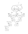
- FIG. 1 is a diagram showing a configuration of a mobile communication system 1 according to an embodiment.
- the mobile communication system 1 is a fifth generation (5G) mobile communication system based on the 3GPP standard.
- the wireless access system in the mobile communication system 1 is NR (New Radio), which is a 5G wireless access system.
- NR New Radio
- LTE Long Term Evolution
- the mobile communication system 1 has a 5G core network (5GC) 10, a user device (UE: User Equipment) 100, a base station (called gNB) 200, and an IAB node 300.
- the IAB node 300 is an example of a relay device.
- the base station is an NR base station
- the base station may be an LTE base station (that is, eNB).
- the 5GC10 has an AMF (Access and Mobility Management Function) 11 and an UPF (User Plane Function) 12.
- the AMF 11 is a device that performs various mobility controls and the like for the UE 100.
- the AMF 11 manages information on the area in which the UE 100 is located by communicating with the UE 100 using NAS (Non-Access Stratum) signaling.
- the UPF 12 is a device that controls the transfer of user data and the like.
- the gNB 200 is connected to the 5GC10 via an interface called an NG interface. In FIG. 1, three gNB200-1 to gNB200-3 connected to 5GC10 are illustrated.
- the gNB 200 is a fixed wireless communication device that performs wireless communication with the UE 100. When the gNB 200 has a donor function, the gNB 200 performs wireless communication with an IAB node that wirelessly connects to itself.
- the gNB 200 is connected to another gNB 200 in an adjacent relationship via an inter-base station interface called an Xn interface.
- FIG. 1 shows an example in which gNB200-1 is connected to gNB200-2 and gNB200-2.
- Each gNB200-1 may have an aggregation unit (CU: Central Unit) and a distribution unit (DU: Distributed Unit).
- CU Central Unit
- DU Distributed Unit
- Each gNB 200 manages one or more cells.
- Cell is used as a term to indicate the smallest unit of wireless communication area.
- the cell may be used as a term for a function or resource for wireless communication with the UE 100.
- One cell belongs to one carrier frequency.
- the UE 100 is a mobile wireless communication device that performs wireless communication with the gNB 200.
- the UE 100 may perform wireless communication with the IAB node 300.
- the UE 100 may be a device that performs wireless communication with the gNB 200 or the IAB node 300.
- the UE 100 is a mobile phone terminal, a tablet terminal, a notebook PC, a sensor or a device provided in the sensor, and / or a vehicle or a device provided in the vehicle.
- FIG. 1 shows an example in which UE 100-1 is wirelessly connected to gNB200-1, UE100-2 is wirelessly connected to IAB node 300-1, and UE100-3 is wirelessly connected to IAB node 300-2. ing.
- UE100-1 directly communicates with gNB200-1.
- the UE 100-2 indirectly communicates with the gNB 200-1 via the IAB node 300-1.
- the UE 100-3 indirectly communicates with the gNB 200-1 via the IAB node 300-1 and the IAB node 300-2.
- the IAB node 300 is a device (relay device) that intervenes in the communication between the eNB 200 and the UE 100 and relays the communication.
- FIG. 1 shows an example in which the IAB node 300-1 is wirelessly connected to the donor device gNB200-1 and the IAB node 300-2 is wirelessly connected to the IAB node 300-1.
- Each IAB node 300 manages a cell.
- the cell ID of the cell managed by the IAB node 300 may be the same as or different from the cell ID of the cell of the donor gNB200-1.
- the IAB node 300 has a UE function unit (user device function unit) and a gNB function unit (base station function unit).
- a UE functional unit may be referred to as MT
- a gNB functional unit may be referred to as DU.
- the IAB node 300 performs wireless communication with a higher-level device (gNB 200 or a higher-level IAB node 300) by its own UE functional unit (MT), and also performs wireless communication with a lower-level device (UE 100 or lower IAB) by its own gNB functional unit (DU). Wireless communication with node 300) is performed.
- the UE function unit (MT) means at least a part of the functions of the UE 100, and the IAB node 300 does not necessarily have all the functions of the UE 100.
- the gNB functional unit (DU) means at least a part of the functions of the gNB 200, and the IAB node 300 does not necessarily have all the functions of the gNB 200.
- the gNB functional unit (DU) may not have an RRC layer, a PDCP layer, or the like.
- the radio section between the UE 100 and the IAB node 300 or gNB 200 may be referred to as an access link (or Uu).
- the radio section between the IAB node 300 and the gNB 200 or other IAB node 300 may be referred to as a backhaul link (or Un).
- a backhaul link may be referred to as a fronthaul link.
- a millimeter wave band may be used for the access link and the backhaul link.
- the access link and the backhaul link may be multiplexed by time division and / or frequency division.
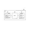
- FIG. 2 is a diagram showing the configuration of gNB 200.
- the gNB 200 has a wireless communication unit 210, a network communication unit 220, and a control unit 230.
- the wireless communication unit 210 is used for wireless communication with the UE 100 and wireless communication with the IAB node 300.
- the wireless communication unit 210 has a receiving unit 211 and a transmitting unit 212.
- the receiving unit 211 performs various types of reception under the control of the control unit 230.
- the receiving unit 211 includes an antenna, converts the radio signal received by the antenna into a baseband signal (received signal), and outputs the radio signal to the control unit 230.
- the transmission unit 212 performs various transmissions under the control of the control unit 230.
- the transmission unit 212 includes an antenna, converts a baseband signal (transmission signal) output by the control unit 230 into a radio signal, and transmits the baseband signal (transmission signal) from the antenna.
- the network communication unit 220 is used for wired communication (or wireless communication) with 5GC10 and wired communication (or wireless communication) with another adjacent gNB200.
- the network communication unit 220 has a reception unit 221 and a transmission unit 222.
- the receiving unit 221 performs various types of reception under the control of the control unit 230.
- the receiving unit 221 receives a signal from the outside and outputs the received signal to the control unit 230.
- the transmission unit 222 performs various transmissions under the control of the control unit 230.
- the transmission unit 222 transmits the transmission signal output by the control unit 230 to the outside.
- the control unit 230 performs various controls on the gNB 200.
- the control unit 230 includes at least one memory and at least one processor electrically connected to the memory.
- the memory stores a program executed by the processor and information used for processing by the processor.
- the processor may include a baseband processor and a CPU.
- the baseband processor modulates / demodulates and encodes / decodes the baseband signal.
- the CPU executes a program stored in the memory to perform various processes.
- the processor executes a process described later.
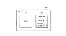
- FIG. 3 is a diagram showing the configuration of the IAB node 300.
- the IAB node 300 has a wireless communication unit 310 and a control unit 320.
- the IAB node 300 may have a plurality of wireless communication units 310.
- the wireless communication unit 310 is used for wireless communication with the gNB 200 (backhaul link) and wireless communication with the UE 100 (access link).
- the wireless communication unit 310 for backhaul link communication and the wireless communication unit 310 for access link communication may be provided separately.
- the wireless communication unit 310 has a receiving unit 311 and a transmitting unit 312.
- the receiving unit 311 performs various types of reception under the control of the control unit 320.
- the receiving unit 311 includes an antenna, converts the radio signal received by the antenna into a baseband signal (received signal), and outputs the radio signal to the control unit 320.
- the transmission unit 312 performs various transmissions under the control of the control unit 320.
- the transmission unit 312 includes an antenna, converts the baseband signal (transmission signal) output by the control unit 320 into a radio signal, and transmits the baseband signal (transmission signal) from the antenna.
- the control unit 320 performs various controls on the IAB node 300.
- the control unit 320 includes at least one memory and at least one processor electrically connected to the memory.
- the memory stores a program executed by the processor and information used for processing by the processor.
- the processor may include a baseband processor and a CPU.
- the baseband processor modulates / demodulates and encodes / decodes the baseband signal.
- the CPU executes a program stored in the memory to perform various processes.
- the processor executes a process described later.
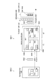
- FIG. 4 is a diagram showing the configuration of the UE 100. As shown in FIG. 4, the UE 100 has a wireless communication unit 110 and a control unit 120.
- the wireless communication unit 110 is used for wireless communication on the access link, that is, wireless communication with the gNB 200 and wireless communication with the IAB node 300.
- the wireless communication unit 110 has a receiving unit 111 and a transmitting unit 112.
- the receiving unit 111 performs various types of reception under the control of the control unit 120.
- the receiving unit 111 includes an antenna, converts the radio signal received by the antenna into a baseband signal (received signal), and outputs the radio signal to the control unit 120.
- the transmission unit 112 performs various transmissions under the control of the control unit 120.
- the transmission unit 112 includes an antenna, converts a baseband signal (transmission signal) output by the control unit 120 into a radio signal, and transmits the baseband signal (transmission signal) from the antenna.
- the control unit 120 performs various controls on the UE 100.
- the control unit 120 includes at least one memory and at least one processor electrically connected to the memory.
- the memory stores a program executed by the processor and information used for processing by the processor.
- the processor may include a baseband processor and a CPU.
- the baseband processor modulates / demodulates and encodes / decodes the baseband signal.
- the CPU executes a program stored in the memory to perform various processes.
- the processor executes a process described later.
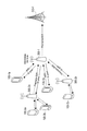
- FIG. 5 is a diagram showing an example of the network configuration of the mobile communication system 1 according to the embodiment.
- the mobile communication system 1 uses NR for the backhaul to enable wireless relay of NR access.
- the donor gNB200-1 is a terminal node of the NR backhaul on the network side, and is a gNB200 having an additional function of supporting IAB.
- the backhaul can be multi-hop through multiple hops.
- the gNB 200 may be separated into a gNB-CU function and a gNB-DU function.
- Each IAB node 300 has a gNB-DU function (base station function unit).
- the gNB-DU function is simply referred to as "DU”.
- the DU terminates the NR Uu radio interface to the UE 100 and lower IAB nodes.
- the DU also supports the F1 protocol to gNB-CU (hereinafter simply referred to as "CU") on donor gNB200-1.
- Neighboring nodes (ie, subordinate devices) on the DU's NR access interface are sometimes referred to as "child nodes.”
- Each IAB node 300 supports an NR Uu wireless interface with an MT function (UE function unit).
- the MT function is simply referred to as "MT".
- the MT connects to the upper IAB node or the DU of the donor gNB200-1, and also connects to the CU of the donor gNB200-1 using the RRC.
- MT establishes a signaling radio bearer (SRB) carrying RRC and NAS messages with donor gNB200-1.
- SRB signaling radio bearer
- Adjacent nodes (ie, host devices) on the MT's NR Uu radio interface are sometimes referred to as "parent nodes.”
- All IAB nodes 300 connected to the donor gNB200-1 via one or more hops form a DAG (Directed Acyclic Graph) topology with the donor gNB200-1 as the root.
- This DAG topology is sometimes referred to as the IAB topology.
- upstream refers to the direction of the parent node and "downstream” refers to the direction of the child node.
- the F1 protocol refers to a communication protocol between CU and DU.
- the F1 protocol includes a control plane protocol, the F1-C protocol, and a user plane protocol, the F1-U protocol.
- FIG. 6 is a diagram showing an example of a protocol stack for the F1-U protocol.
- the donor gNB200-1 includes GTP-U (GPRS Tunneling Protocol for User Plane), UDP (User Datagram Protocol), IP (Internet Protocol), and BAP (Backhaul Protocol). It has (Radio Link Control), MAC (Medium Access Control), and PHY (Physical layer) layers.
- GTP-U GPRS Tunneling Protocol for User Plane
- UDP User Datagram Protocol
- IP Internet Protocol
- BAP Backhaul Protocol
- It has (Radio Link Control), MAC (Medium Access Control), and PHY (Physical layer) layers.
- the downstream IAB node 300-2 communicates with the donor gNB200-1 via the intermediate node IAB node 300-1.
- the IAB node 300-2 like the donor gNB200-1, has layers of GTP-U, UDP, IP, BAP, RLC, MAC, and PHY.
- the IAB node 300-1 which is an intermediate node, has each functional part of MT and DU.
- the MT has layers of BAP, RLC, MAC, and PHY.
- the DU has layers of BAP, RLC, MAC, and PHY.
- FIG. 6 shows an example in which the BAP layer of the DU and the BAP layer of the MT are separately provided, the BAP layer of the DU and the BAP layer of the MT may be integrated.
- the PHY layer performs coding / decoding, modulation / demodulation, antenna mapping / demapping, and resource mapping / demapping. Data and control information are transmitted between the PHY layers via physical channels.
- the MAC layer performs priority control of data and retransmission processing by hybrid ARQ (HARQ). Data and control information are transmitted between the MAC layers via a transport channel.
- the MAC layer of the donor gNB200 and the MAC layer of the DU include a scheduler. The scheduler determines the transport format (transport block size, modulation / coding method (MCS)) of the upper and lower links and the resource block allocated to the UE 100.
- MCS modulation / coding method
- the RLC layer transmits data to the receiving RLC layer by using the functions of the MAC layer and the PHY layer. Data and control information are transmitted between the RLC layers via a logical channel.
- the BAP layer performs routing processing and bearer mapping / demapping processing in the user plane.
- FIG. 7 is a diagram showing an example of a protocol stack for the F1-C protocol. Here, the differences from the F1-U protocol will be described.
- the donor gNB200-1 has F1-AP (Application Protocol) and SCTP (Stream Control Transmission Protocol) layers instead of the GTP-U and UDP layers shown in FIG. .
- the downstream IAB node 300-2 has F1-AP and SCPP layers instead of the GTP-U and UDP layers shown in FIG.
- FIG. 8 is a diagram showing an operation related to the preemptive BSR according to the embodiment.
- the IAB node 300-1 is an intermediate IAB node (Intermediate IAB node), and the IAB node 300-2 is a downstream IAB node (Downstream IAB node).
- the lower device of the IAB node 300-1 is the downstream IAB node
- the lower device of the IAB node 300-1 may be the UE 100.
- the superior device of the IAB node 300-1 is the donor gNB200-1
- the superior device of the IAB node 300-1 may be an upstream IAB node. That is, at least one IAB node may intervene between the IAB node 300-1 and the donor gNB200-1.
- the IAB node 300-1 has a DU that wirelessly connects to the IAB node 300-2 and an MT that wirelessly connects to the host device, and relays upstream data from the IAB node 300-2 to the host device.
- the MT MAC layer transmits a preemptive BSR (Preemptive BSR) indicating the amount of untransmitted upstream data to a higher-level device.
- Preemptive BSR Preemptive BSR
- the BSR transmitted by the UE 100 sets the amount of untransmitted data (that is, the amount of uplink buffer) of each layer of MAC, RLC, and PDCP as a logical channel group (LCG). It is shown for each.
- Each LCG consists of at least one logical channel and is a group set according to priority.
- Legacy BSR formats include short BSR and long BSR.
- the short BSR includes a field in which the LCG ID is stored and a buffer size field in which information indicating the amount of untransmitted data is stored.
- the long BSR includes a field in which a bit string indicating the presence or absence of a buffer size field for each LCG is stored, and a plurality of buffer size fields.
- the gNB 200 grasps the amount of untransmitted data of the UE 100 for each LCG based on the BSR from the UE 100, and schedules the UE 100 to allocate the uplink radio resource corresponding to the amount of the untransmitted data.
- the IAB node 300-1 has a DU (base station function unit) as well as an MT (UE function unit), and there may be an IAB node 300-2 connected to this DU. Therefore, if only the amount of untransmitted data (Legacy buffer size) of the MT of the IAB node 300-1 is reported to the host device, the host device performs scheduling in consideration of the potential amount of untransmitted data (Expected buffer size). Can't. Therefore, there is a problem that there is a shortage or a delay in allocating the uplink radio resource to the IAB node 300-2.
- DU base station function unit
- MT UE function unit
- the preemptive BSR reflects at least one of the amount of data accumulated in the DU of the IAB node 300-1 and the amount of untransmitted data of the IAB node 300-2 connected to this DU. ..
- the host device can perform scheduling in consideration of the potential amount of untransmitted data, so that it is possible to prevent shortages and delays in the allocation of uplink radio resources. For example, when a radio resource is not allocated to the backhaul link (that is, MT) of the IAB node 300-1, the scheduling request can be transmitted to the upper node by triggering the preemptive BSR. By transmitting this scheduling request, appropriate radio resource allocation can be prepared before the actual upstream data reaches the MT transmission protocol (that is, RLC, MAC).
- the amount of untransmitted upstream data indicated by preemptive BSR includes the following variations A) to C).
- the preemptive BSR indicates the amount of untransmitted upstream data of the own IAB node 300 and the amount of untransmitted upstream data of the lower device connected to the own IAB node 300, respectively.
- FIG. 9 is a diagram showing a configuration example 1 of the preemptive BSR according to the embodiment.
- the IAB node # 1 transmits a preemptive BSR indicating the untransmitted upstream data amount A of the own IAB node to the IAB node # 2.
- the IAB node # 2 transmits a preemptive BSR indicating the untransmitted upstream data amount B of the own IAB node and the untransmitted upstream data amount A of the IAB node # 1 to the IAB node # 3.
- the IAB node # 3 transmits a preemptive BSR indicating the untransmitted upstream data amount C of the own IAB node and the untransmitted upstream data amount B of the IAB node # 2 to the IAB node # 4.
- the IAB node # 4 transmits a preemptive BSR indicating the untransmitted upstream data amount D of the own IAB node and the untransmitted upstream data amount C of the IAB node # 3 to the IAB node # 4.
- the preemptive BSR includes the amount of untransmitted upstream data of the own IAB node 300, the amount of untransmitted upstream data of the lower device connected to the own IAB node 300, and the amount of untransmitted data of the lower device of the lower device. Each of is shown.
- FIG. 10 is a diagram showing a configuration example 2 of the preemptive BSR according to the embodiment.
- the IAB node # 1 transmits a preemptive BSR indicating the untransmitted upstream data amount A of the own IAB node to the IAB node # 2.
- the IAB node # 2 transmits a preemptive BSR indicating the untransmitted upstream data amount B of the own IAB node and the untransmitted upstream data amount A of the IAB node # 1 to the IAB node # 3.
- the IAB node # 3 is a preemptive BSR indicating the untransmitted upstream data amount C of the own IAB node, the untransmitted upstream data amount B of the IAB node # 2, and the untransmitted upstream data amount A of the IAB node # 1.
- the IAB node # 4 has the untransmitted upstream data amount D of the own IAB node, the untransmitted upstream data amount C of the IAB node # 3, the untransmitted upstream data amount B of the IAB node # 2, and the IAB node #.
- a preemptive BSR indicating the amount of untransmitted upstream data A of 1 is transmitted to IAB node # 4.
- the preemptive BSR may be a new MAC CE having a format different from that of the legacy BSR.
- the format of the preemptive BSR may be a format having a separate buffer size field in which the amount of untransmitted upstream data of each node is stored.
- the preemptive BSR does not indicate the amount of untransmitted upstream data of the own IAB node 300, but indicates the amount of untransmitted upstream data of the lower device connected to the own IAB node 300.
- the legacy BSR indicates the amount of untransmitted upstream data of the own IAB node 300 to the upper device
- the preemptive BSR indicates the amount of untransmitted upstream data of the lower device. Can be done. Therefore, the preemptive BSR may be used only for reporting the amount of untransmitted upstream data of the lower device. Similar to B) above, it may indicate the amount of untransmitted data of the lower device of the lower device.
- the format of the preemptive BSR may be a new MAC control element (MAC CE) whose format is different from that of the legacy BSR.
- the preemptive BSR may be in a format that has a separate buffer size field for each node.
- the preemptive BSR format may be a diversion of the legacy BSR format.
- the legacy BSR can indicate the amount of untransmitted upstream data for each node.
- the configuration of the preemptive BSR as in A) above is mainly assumed, but the configuration of the preemptive BSR as in B) or C) above may be used.
- the preemptive BSR shows the following data amounts BS # 1 and # 2 in the same manner as the data amount (Legacy buffer size) indicated by the legacy BSR.
- the preemptive BSR indicates at least one of the following data amounts BS # 3 to # 6.
- Data amount BS # 3 indicated by BSR from IAB node 300-2 is a Data amount BS # 3 indicated by BSR from IAB node 300-2.
- the amount of uplink radio resources that is, the size of the uplink grant
- the uplink grant size BS # 3' may be used instead of the data amount BS # 3 indicated by the BSR.
- the DU MAC layer notifies the MT MAC layer of this data amount BS # 3 (MAC data amount).
- the DU MAC layer may indirectly notify the MT MAC layer of the data amount BS # 3 indicated by the BSR from the IAB node 300-2 via the BAP layer, or may notify the BAP layer. You may notify directly without going through.
- the MT MAC layer considers the notified data amount BS # 3 as part of the amount of upstream data retained in the transmission MAC layer of IAB node 300-1 and IAB node 300-1. Calculate the amount of untransmitted upstream data in.
- the MT MAC layer transmits a preemptive BSR (second BSR) indicating the calculated amount of untransmitted upstream data to the higher-level device.
- second BSR preemptive BSR
- the host device can perform scheduling in consideration of the amount of untransmitted upstream data BS # 3 of the IAB node 300-2.
- the DU MAC layer determines whether to notify the MT MAC layer of the data amount BS # 3, that is, whether to enable or disable the notification to the MT MAC layer in logical channel units or LCG units. Alternatively, they may be switched at once.
- the MAC layer of the DU enable notification to the MAC layer of the MT according to the settings made by the donor gNB200-1 to the IAB node 300-1 (for example, the setting by RRC message or F1 message)?
- it may be disabled in logical channel units, LCG units, or in a batch.
- the logical channel or LCG to be notified to the MAC layer of the MT may be specified by the donor gNB200-1.
- the BSR (first BSR) received by the IAB node 300-1 from the IAB node 300-2 may be the configuration of A) above.
- This BSR contains the first buffer state information (first buffer size field) indicating the amount of untransmitted upstream data of the IAB node 300-2 and the untransmitted upstream data of the device further lower than the IAB node 300-2.
- second buffer state information (second buffer size field) indicating the amount.
- the MAC layer of the MT sets the amount of the first untransmitted upstream data indicated by the first buffer state information among the first buffer state information and the second buffer state information to the IAB node 300-1. Treat as part of the amount of upstream data stored in the MAC layer. That is, the MAC layer of the MT sets the amount of untransmitted upstream data of the device lower than the IAB node 300-2 as a part of the amount of upstream data retained in the MAC layer of the IAB node 300-1. Without considering it, a preemptive BSR that does not indicate the amount of untransmitted upstream data of the device below the IAB node 300-2 is generated.
- the DU MAC layer notifies the MT MAC layer of the first buffer state information without notifying the MT MAC layer of the second buffer state information. May be good. This allows the MT MAC layer to generate a preemptive BSR that does not indicate the amount of untransmitted upstream data in the device below the IAB node 300-2.
- the IAB node 300-1 may receive both the preemptive BSR (third BSR) and the legacy BSR (first BSR) of C) above from the IAB node 300-2.
- Such a preemptive BSR indicates the amount of untransmitted upstream data of the device below the IAB node 300-2.
- the legacy BSR indicates the amount of untransmitted upstream data of the IAB node 300-2.
- the MAC layer of the MT has the amount of untransmitted upstream data indicated by the legacy BSR among the preemptive BSR and the legacy BSR of the upstream data retained in the MAC layer of the IAB node 300-1. Treat as part of the quantity. That is, the MAC layer of the MT sets the amount of untransmitted upstream data of the device lower than the IAB node 300-2 as a part of the amount of upstream data retained in the MAC layer of the IAB node 300-1. Without considering it, a preemptive BSR that does not indicate the amount of untransmitted upstream data of the device below the IAB node 300-2 is generated.
- the DU MAC layer may notify the MT MAC layer of the data amount indicated by the legacy BSR without notifying the MT MAC layer of the data amount indicated by the preemptive BSR. This allows the MT MAC layer to generate a preemptive BSR that does not indicate the amount of untransmitted upstream data in the device below the IAB node 300-2.
- the IAB node 300-1 may receive a preemptive BSR diverted from the legacy BSR format from the IAB node 300-2.
- each backhaul link (each node) is associated with the LCG, and the node can be identified by the LCG.
- the legacy BSR has a first buffer state information indicating the amount of untransmitted upstream data associated with the first LCG and a second buffer state information indicating the amount of untransmitted upstream data associated with the second LCG. And include.
- the first LCG is associated with a link (first backhaul link) between the IAB node 300-1 and the IAB node 300-2.
- the second LCG is associated with a link (second backhaul link) between the IAB node 300-2 and the device below the IAB node 300-2.
- the MAC layer of MT sets the amount of untransmitted upstream data indicated by the first buffer state information among the first buffer state information and the second buffer state information to the MAC layer of the IAB node 300-1. Treat as part of the amount of upstream data stored in. That is, the MAC layer of the MT sets the amount of untransmitted upstream data of the device lower than the IAB node 300-2 as a part of the amount of upstream data retained in the MAC layer of the IAB node 300-1. Without considering it, a preemptive BSR that does not indicate the amount of untransmitted upstream data of the device below the IAB node 300-2 is generated.
- the DU MAC layer notifies the MT MAC layer of the first buffer state information without notifying the MT MAC layer of the second buffer state information. May be good. This allows the MT MAC layer to generate a preemptive BSR that does not indicate the amount of untransmitted upstream data in the device below the IAB node 300-2.
- the MAC layer of the DU notifies the MAC layer of the MT of the amount of upstream data BS # 4 (the amount of MAC data) retained in the MAC layer of the DU.
- the amount of upstream data retained in the MAC layer of the DU may be limited to the data that the MAC layer of the DU succeeds in receiving (specifically, decoding).
- the MAC layer of the DU may be a packet for which HARQ ACK has been transmitted to the IAB node 300-2, or the amount of data retained in the HARQ buffer of the MAC layer of the DU may be excluded. ..
- the MAC layer of the DU may indirectly notify the MAC layer of the MT via the BAP layer of the amount of upstream data BS # 4 accumulated in the MAC layer of the DU, or may not go through the BAP layer. May be notified directly to.
- the MT MAC layer considers the notified upstream data amount BS # 4 as part of the amount of upstream data retained in the MAC layer of the IAB node 300-1 and the IAB node 300. Calculate the amount of untransmitted upstream data of -1.
- the MT MAC layer transmits a preemptive BSR indicating the calculated amount of untransmitted upstream data to the host device.
- the host device can perform scheduling in consideration of the amount of upstream data BS # 4 accumulated in the MAC layer of the DU.
- the DU MAC layer determines whether to notify the MT MAC layer of the data amount BS # 4, that is, whether to enable or disable the notification to the MT MAC layer in logical channel units or LCG units. Alternatively, they may be switched at once. For example, does the MAC layer of the DU enable notification to the MAC layer of the MT according to the settings made by the donor gNB200-1 to the IAB node 300-1 (for example, the setting by RRC message or F1 message)? Alternatively, it may be disabled in logical channel units, LCG units, or in a batch. Specifically, the logical channel or LCG to be notified to the MAC layer of the MT may be specified by the donor gNB200-1. Alternatively, it may be possible to collectively set whether or not to notify the MAC layer of the MT.
- MAC setting information (MAC main control.) Transmitted by RRC from the donor gNB200-1 to the IAB node 300-1, information (flag, etc.) indicating whether or not to handle as the amount of MAC data for each LCG is provided. It may be possible to set.
- the RLC layer of the DU notifies the MAC layer of the MT of the amount of upstream data BS # 5 (RLC data amount) retained in the RLC layer of the DU.
- the amount of upstream data retained in the RLC layer of the DU may be limited to the data that the RLC layer of the DU succeeds in receiving.
- the RLC layer of the DU may be a packet for which the ARQ ACK has been transmitted to the IAB node 300-2 (that is, a packet other than the packet corresponding to waiting for the transmission of the ARQ ACK), or the ARQ buffer of the RLC layer of the DU.
- the amount of data retained in the sliding window may be excluded.
- the RLC layer of the DU may indirectly notify the MAC layer of the MT via the BAP layer of the amount of upstream data BS # 5 accumulated in the RLC layer of the DU, or may not go through the BAP layer. May be notified directly to.
- the MT MAC layer considers the amount of notified upstream data as part of the amount of upstream data retained in the RLC layer of IAB node 300-1 and of IAB node 300-1. Calculate the amount of untransmitted upstream data.
- the MT MAC layer transmits a preemptive BSR indicating the calculated amount of untransmitted upstream data to the host device.
- the host device can perform scheduling in consideration of the amount of upstream data BS # 5 accumulated in the RLC layer of the DU.
- the RLC layer of the DU may switch whether to enable or disable the notification of the data amount BS # 5 to the MAC layer of the MT on a logical channel basis or in a batch.
- the RLC layer of the DU is a logical channel to enable or disable notifications depending on the settings made by the donor gNB200-1 to the IAB node 300-1 (for example, the settings by RRC message or F1 message). It may be switched in units or in batches.
- logical channel setting information (logical channel configuration.) Transmitted by RRC from the donor gNB200-1 to the IAB node 300-1
- Amount of upstream data accumulated in the BAP layer BS # 6 First, the BAP layer of the IAB node 300-1 notifies the MAC layer of the MT of the amount of upstream data BS # 6 (BAP data amount) retained in the BAP layer.
- the BAP layer may also notify the MT MAC layer together with these data amounts.
- the BAP layer may notify the MAC layer of the MT as separate data amounts for MAC, RLC, and BAP.
- the BAP layer may notify the MAC layer of the MT as a separate amount of data for each logical channel ID.
- the BAP layer may notify the MAC layer for each LCG (logical channel group), and the LCG may follow the LCG setting (of the MAC layer) of the MT.
- the BAP layer may add the amount of MAC data and the amount of RLC data to the amount of BAP data and notify the MAC layer of MT as one piece of information.
- the MAC layer of MT considers the notified amount of upstream data BS # 6 as part of the amount of upstream data retained in IAB node 300-1 and of IAB node 300-1. Calculate the amount of untransmitted upstream data.
- the MT MAC layer transmits a preemptive BSR indicating the calculated amount of untransmitted upstream data to the host device.
- the BAP layer may switch whether to enable or disable the notification of the data amount BS # 6 to the MAC layer of the MT on a logical channel basis or in a batch. For example, depending on the setting made by the donor gNB200-1 to the IAB node 300-1 (for example, the setting by the RRC message or the F1 message), whether to enable or disable the notification is set for each logical channel or collectively. You may switch with.
- information indicating whether or not to handle as the amount of BAP data may be set for each logical channel ID.
- the logical channel ID to be set whether or not to handle as the amount of BAP data may be the logical channel ID on the DU side (logical channel ID on the receiving side) or the logical channel ID on the MT side (transmission). It may be a side logical channel ID).
- bearer mapping that is, mapping between the logical channel ID on the DU side and the logical channel ID on the MT side, either one of the logical channel IDs can be used for the setting.
- the target for setting whether or not to handle as the amount of BAP data may be the ID of the source IAB node (that is, the lower device) or the ID of the destination IAB node (that is, the higher device). Good.
- the source and destination may be the most recent IAB node, or may be a source and destination several hops away.
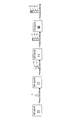
- FIG. 11 is a diagram showing an example of the operation flow of the IAB node 300-1 according to the embodiment.
- step S1 the MAC layer of the DU of the IAB node 300-1 receives the BSR from the lower device IAB node 300-2.
- step S2 the MAC layer of the DU of the IAB node 300-1 specifies the amount of data indicated by the BSR received from the IAB node 300-2, and notifies the MAC layer of the MT of the IAB node 300-1 of the specified amount of data. To do.
- the MAC layer of the DU of the IAB node 300-1 calculates the amount of upstream data accumulated in itself, and notifies the calculated amount of data to the MAC layer of the MT of the IAB node 300-1.
- the RLC layer of the DU of the IAB node 300-1 calculates the amount of upstream data accumulated in itself, and notifies the calculated amount of data to the MAC layer of the MT of the IAB node 300-1.
- the BAP layer of the IAB node 300-1 calculates the amount of upstream data accumulated in itself, and notifies the calculated amount of data to the MAC layer of the MT of the IAB node 300-1.
- step S3 the MAC layer of the MT of the IAB node 300-1 adds up the amount of data notified from each layer of the MAC, RLC, and BAP of the DU of the IAB node 300-1, and is a preemptive indicating the total amount of data.
- BSR is transmitted to the host device.
- the MAC layer of the MT of the IAB node 300-1 is the amount of untransmitted upstream data of the IAB node 300-2 (that is, the data indicated by the BSR received from the IAB node 300-2).
- the buffer size field indicating the amount
- the amount of untransmitted upstream data of the IAB node 300-1 that is, the total value of the accumulated data amount of each layer of the DU MAC, RLC, and BAP of the IAB node 300-1).
- a preemptive BSR containing the indicated buffer size field may be transmitted to the host device.
- the IAB node 300-1 is to show that it is a preemptive BSR.
- the identifier of may be included in the preemptive BSR.
- the preemptive BSR is a BSR that reflects the amount of untransmitted upstream data other than the amount of untransmitted upstream data of the MT.
- the IAB node 300-1 may indicate to the host device that it is a preemptive BSR by including the logical channel ID specified for the preemptive BSR in the header portion (MAC subheader) transmitted together with the BSR MAC CE. Good.
- a base station (hereinafter, referred to as a master base station) that manages each IAB node 300 may exist in addition to the donor gNB 200.
- the master base station may be an LTE base station.
- the MT of each IAB node 300 may have two connections (ie, dual connections), one with a master base station and one with a host device (upper IAB node or donor gNB).
- the master base station may be a master node, and the connection may be an MCG (Master Cell Group) link.
- the higher-level device (upper IAB node or donor gNB) may be a secondary node, and the connection may be an SCG (Secondary Cell Group) link.
- the base station in the mobile communication system 1 may be an eNB which is an LTE base station.
- the core network in the mobile communication system 1 may be an EPC (Evolved Packet Core).
- the gNB may be connected to the EPC
- the eNB may be connected to the 5GC
- the gNB and the eNB may be connected via the inter-base station interface (Xn interface, X2 interface).
- the preemptive BSR may be transmitted by the UE 100, which does not have to belong to the IAB topology.
- the UE 100 may notify as a preemptive BSR by reflecting a data other than the amount of data retained in its own MAC, RLC, PDCP, and SDAP.
- the preemptive BSR may be triggered by, for example, a data amount notification from the application layer.
- a packet for example, a packet having a high priority or a high QoS request
- TSC Time Sensitive Communication: communication with strict time constraint
- a program for causing a computer to execute each process according to the above-described embodiment may be provided.
- the program may also be recorded on a computer-readable medium.
- Computer-readable media can be used to install programs on a computer.
- the computer-readable medium on which the program is recorded may be a non-transient recording medium.
- the non-transient recording medium is not particularly limited, but may be, for example, a recording medium such as a CD-ROM or a DVD-ROM.
- a chipset composed of a memory for storing a program for executing each process performed by the UE 100, the gNB 200, or the IAB node 300 and a processor for executing the program stored in the memory may be provided.
- preemptive BSR regular BSR
- -R2 is a trigger of both types of preemptive BSR (1. based on UL grants provided to child nodes and / or UEs, 2. based on BSRs from child nodes or UEs) in IAB Rel-16 operation. It is assumed that it can be supported. Further consideration is needed as to what is specified.
- the preemptive BSR is used for buffer status reporting based on the amount of data that will be available on the MT, as well as the data available for transmission on the MT's MAC and RLC. There is expected. The agreement itself only mentions the triggering conditions for preemptive BSR, but is implied by the current assumption "1. Based on the UL grant provided to the child node and / or UE, 2. Based on the BSR from the child node or UE". I think it will be done.
- Preemptive BSR is expected to report the buffer size of the MAC, RLC, and BAP of the IAB node in addition to the buffer size of the downstream IAB node / UE, in addition to the existing rules.
- the regular BSR is triggered as shown below.
- the MAC entity determines the amount of UL data that can be used in the logical channel according to the data amount calculation procedure of TS38.322 and TS38.323.
- BSR is triggered when any of the following events occur.
- the BSR is referred to as the "regular BSR".
- Finding 2 Regular BSR is triggered when UL data becomes available to the MAC entity according to the data volume calculation procedure in RLC (and PDCP).
- the UE For MAC buffer status reporting, the UE considers the following as the RLC data volume: -RLC SDU and RLC SDU segment not yet included in the RLC data PDU-RLC data PDU with initial transmission pending -RLC data PDU (RLC AM) whose retransmission is pending
- RLC AM initial transmission pending -RLC data PDU
- the UE estimates the size of the STATUS PDU sent at the next transmission opportunity and considers this as part of the RLC data volume. ..
- Finding 3 The existing data volume calculation procedure is applicable only to MT RLC.
- the data volume calculation procedure should be extended to support preemptive BSR.
- the following amount of data should be considered.
- -MAC (receiver, i.e. on DU):
- the buffer size reported by the (existing) BSR from the downstream node / UE, and the MAC PDU and MAC SDU still on the MAC receiver are the amount of MAC data. Be considered.
- RLC reception side, that is, on the DU
- RLC PDU and RLC SDU that are still on the reception side of RLC are regarded as the amount of RLC data.
- BAP PDU still in the routing process is regarded as the amount of BAP data.
- the amount of these additional data is finally notified to the MAC (transmitter, that is, on the MT) and reported in the preemptive BSR.
- Proposal 1 RAN2 will include the buffer size reported by the BSR from the downstream node / UE, and the MAC PDU and MAC SDU still on the receiving side of the MAC in the MAC specifications for data volume calculation. You should agree.
- Proposal 2 RAN2 should agree that RLC PDUs and RLC SDUs, which are still on the receiving side of RLC, are included in the RLC specifications for RLC data volume calculation.
- Proposal 3 RAN2 should agree, for example, that BAP PDUs that are still in the routing process are included in the BAP specifications for BAP data volume calculation.
- the preemptive BSR is used for scheduling radio resources. That is, the behavior of the downstream node (in this case the intermediate node) must be deterministic and controllable. Therefore, activation / deactivation of each procedure should depend on the configuration via RRC or F1-AP.
- Proposal 4 RAN2 should discuss whether additional data volume calculation procedures can be activated / deactivated through configuration via RRC or F1-AP.
- MAC CE format Another point of discussion in the email discussion is whether to reuse the existing BSR MAC CE or define a new preemptive BSR MAC CE. In other words, from the perspective of the upstream DU scheduler, it has not yet been determined whether the "expected data volume" should be distinguished from the existing buffer size.
- the preemptive BSR may include buffer reports for all downstream IAB nodes (ie, children, grandchildren, great-grandchildren: option 1), as shown in FIGS. 9 and 10. It is not clear whether only the closest hop (ie child and itself: option 2) is included.
- Finding 4 It is not clear whether the preemptive BSR includes the buffer size of all downstream nodes on the multi-hop backhaul.
- Option 1 may provide the best performance for low latency scheduling when resource allocation and UL data transmission over multi-hop backhaul are done in a timely manner. Otherwise, overscheduling can occur in upstream backhaul.
- option 2 is a kind of hop-by-hop scheduling, so it is a safer scheme.
- Option 1 is an issue or configurable, a new MAC CE should be introduced to distinguish the expected amount of data from the actual buffered data. If not, I think the existing MAC CE will still work well.
- Proposal 5 RAN2 considers not only the viewpoint of scheduler implementation, but also the details of the expected amount of data (ie, one of the closest downstream nodes, or one of all downstream multi-hop nodes). , It should be discussed whether a new MAC CE will be introduced in preemptive BSR.
- R2 states that "R2 is based on both types of preemptive BSR triggers (1. based on UL grants provided to child nodes and / or UEs, 2. based on BSRs from child nodes or UEs), but IAB Rel- It is assumed that 16 operations can be supported. Further consideration is required as to what is specified. " It can be intended that these triggers occur aperiodically, i.e., be triggered by an event. In addition, the two identified types are based on the plural, ie, multiple "UL grants" and "BSRs".
- triggering a preemptive BSR to the upstream is to provide multiple events downstream, ie BSR reception or UL authorization. is connected with.
- some major problems are observed as follows.
- Proposal 6 RAN2 should discuss preemptive BSR triggers in consideration of multiple downstream nodes.
Landscapes
- Engineering & Computer Science (AREA)
- Computer Networks & Wireless Communication (AREA)
- Signal Processing (AREA)
- Mobile Radio Communication Systems (AREA)
Abstract
Provided is a communication control method comprising a base station function unit that is wirelessly connected to a lower device and a user device function unit that is wirelessly connected to an upper device. The communication control method executed in a relay device that relays upstream data from the lower device to the upper device comprises: receiving, by a MAC layer of the base station function unit, a first buffer status report showing an amount of first untransmitted upstream data of the lower device from the lower device; informing, by the MAC layer of the base station function unit, the MAC layer of the user device function unit of the amount of the first untransmitted upstream data shown by the first buffer status report; calculating, by the MAC layer of the user device function unit, an amount of second untransmitted upstream data of the relay device by regarding the informed amount of the first untransmitted upstream data as a part of an amount of upstream data retained in the MAC layer of the relay device; and transmitting, by the MAC layer of the user device function unit, a second buffer status report showing the calculated amount of the second untransmitted upstream data to the upper device.
Description
本開示は、移動通信システムで用いる通信制御方法に関する。
The present disclosure relates to a communication control method used in a mobile communication system.
移動通信システムの標準化プロジェクトである3GPP(3rd Generation Partnership Project)において、IAB(Integrated Access and Backhaul)ノードと呼ばれる新たな中継装置が検討されている。1又は複数の中継装置がドナー基地局とユーザ装置との間の通信に介在し、この通信に対する中継を行う。
In 3GPP (3rd Generation Partnership Project), which is a standardization project for mobile communication systems, a new relay device called an IAB (Integrated Access and Backhaul) node is being studied. One or more relay devices intervene in the communication between the donor base station and the user device, and relay the communication.
このような中継装置は、ユーザ装置機能部及び基地局機能部を有しており、ユーザ装置機能部を用いて上位装置(基地局又は上位の中継装置)との無線通信を行うとともに、基地局機能部を用いて下位装置(ユーザ装置又は下位の中継装置)との無線通信を行う。
Such a relay device has a user device function unit and a base station function unit, and uses the user device function unit to perform wireless communication with a higher-level device (base station or higher-level relay device) and also to perform wireless communication with the base station. Wireless communication with a lower device (user device or lower relay device) is performed using the functional unit.
第1の態様に係る通信制御方法は、下位装置と無線で接続する基地局機能部と、上位装置と無線で接続するユーザ装置機能部とを有し、前記下位装置から前記上位装置へのアップストリームデータを中継する中継装置において実行する方法である。前記通信制御方法は、前記ユーザ装置機能部のMACレイヤが、前記下位装置の第1未送信アップストリームデータの量を示すプリエンプティブバッファ状態報告を前記上位装置に送信することを有する。前記プリエンプティブバッファ状態報告は、プリエンプティブバッファ状態報告用に規定された論理チャネルIDを含むMACサブヘッダと一緒に送信される。前記プリエンプティブバッファ状態報告のフォーマットは、前記中継装置の未送信アップストリームデータを示すバッファ状態報告のフォーマットと共通である。
The communication control method according to the first aspect includes a base station function unit that wirelessly connects to a lower device and a user device function unit that wirelessly connects to a higher device, and upgrades from the lower device to the higher device. This is a method executed in a relay device that relays stream data. The communication control method includes that the MAC layer of the user device function unit transmits a preemptive buffer state report indicating the amount of first untransmitted upstream data of the lower device to the upper device. The preemptive buffer status report is transmitted with a MAC subheader containing the logical channel ID specified for the preemptive buffer status report. The format of the preemptive buffer status report is the same as the format of the buffer status report indicating untransmitted upstream data of the relay device.
第2の態様に係る通信制御方法は、下位装置と無線で接続する基地局機能部と、上位装置と無線で接続するユーザ装置機能部とを有し、前記下位装置から前記上位装置へのアップストリームデータを中継する中継装置において実行する方法である。前記通信制御方法は、前記ユーザ装置機能部のMACレイヤが、前記下位装置の第1未送信アップストリームデータの量を示すプリエンプティブバッファ状態報告を前記上位装置に送信することを有する。前記プリエンプティブバッファ状態報告を送信することは、前記ユーザ装置機能部のMACレイヤが、前記プリエンプティブバッファ状態報告と共に、前記中継装置の未送信アップストリームデータを示すバッファ状態報告を前記上位装置に送信することを含む。
The communication control method according to the second aspect includes a base station function unit that wirelessly connects to the lower device and a user device function unit that wirelessly connects to the upper device, and upgrades from the lower device to the higher device. This is a method executed in a relay device that relays stream data. In the communication control method, the MAC layer of the user device function unit transmits a preemptive buffer state report indicating the amount of first untransmitted upstream data of the lower device to the upper device. To transmit the preemptive buffer status report, the MAC layer of the user device function unit transmits the buffer status report indicating untransmitted upstream data of the relay device to the higher-level device together with the preemptive buffer status report. including.
第3の態様に係る通信制御方法は、下位装置と無線で接続する基地局機能部と、上位装置と無線で接続するユーザ装置機能部とを有し、前記下位装置から前記上位装置へのアップストリームデータを中継する中継装置において実行する方法である。前記通信制御方法は、前記ユーザ装置機能部のMACレイヤが、前記下位装置の第1未送信アップストリームデータの量を示すプリエンプティブバッファ状態報告を前記上位装置に送信することを有する。前記プリエンプティブバッファ状態報告は、前記第1未送信アップストリームデータの量を示す第1バッファ状態情報及び前記下位装置のさらに下位の装置の未送信アップストリームデータの量を示す第2バッファ状態情報のうち、前記第1バッファ状態情報が示す前記第1未送信アップストリームデータの量を含む。
The communication control method according to the third aspect includes a base station function unit that wirelessly connects to the lower device and a user device function unit that wirelessly connects to the upper device, and upgrades from the lower device to the higher device. This is a method executed in a relay device that relays stream data. In the communication control method, the MAC layer of the user device function unit transmits a preemptive buffer state report indicating the amount of first untransmitted upstream data of the lower device to the upper device. The preemptive buffer state report includes the first buffer state information indicating the amount of the first untransmitted upstream data and the second buffer state information indicating the amount of untransmitted upstream data of the lower device. , The amount of the first untransmitted upstream data indicated by the first buffer state information.
第4の態様に係る中継装置は、下位装置と無線で接続する基地局機能部と、上位装置と無線で接続するユーザ装置機能部とを有し、前記下位装置から前記上位装置へのアップストリームデータを中継する。前記ユーザ装置機能部のMACレイヤが、前記下位装置の第1未送信アップストリームデータの量を示すプリエンプティブバッファ状態報告を前記上位装置に送信する。前記プリエンプティブバッファ状態報告は、プリエンプティブバッファ状態報告用に規定された論理チャネルIDを含む。前記プリエンプティブバッファ状態報告のフォーマットは、前記中継装置の第2未送信アップストリームデータを示すバッファ状態報告のフォーマットと共通である。
The relay device according to the fourth aspect has a base station function unit that wirelessly connects to the lower device and a user device function unit that wirelessly connects to the upper device, and is upstream from the lower device to the higher device. Relay data. The MAC layer of the user device function unit transmits a preemptive buffer state report indicating the amount of first untransmitted upstream data of the lower device to the upper device. The preemptive buffer status report includes a logical channel ID specified for the preemptive buffer status report. The format of the preemptive buffer state report is the same as the format of the buffer state report indicating the second untransmitted upstream data of the relay device.
第5の態様に係る中継装置は、下位装置と無線で接続する基地局機能部と、上位装置と無線で接続するユーザ装置機能部とを有し、前記下位装置から前記上位装置へのアップストリームデータを中継する。前記ユーザ装置機能部のMACレイヤが、前記下位装置の第1未送信アップストリームデータの量を示すプリエンプティブバッファ状態報告を前記上位装置に送信する。前記ユーザ装置機能部のMACレイヤは、前記プリエンプティブバッファ状態報告を送信する場合に、前記プリエンプティブバッファ状態報告と共に、前記中継装置の未送信アップストリームデータを示すバッファ状態報告を前記上位装置に送信する。
The relay device according to the fifth aspect has a base station function unit that wirelessly connects to the lower device and a user device function unit that wirelessly connects to the upper device, and is upstream from the lower device to the higher device. Relay data. The MAC layer of the user device function unit transmits a preemptive buffer state report indicating the amount of first untransmitted upstream data of the lower device to the upper device. When transmitting the preemptive buffer status report, the MAC layer of the user device function unit transmits the buffer status report indicating the untransmitted upstream data of the relay device to the higher-level device together with the preemptive buffer status report.
第6の態様に係る中継装置は、下位装置と無線で接続する基地局機能部と、上位装置と無線で接続するユーザ装置機能部とを有し、前記下位装置から前記上位装置へのアップストリームデータを中継する。前記ユーザ装置機能部のMACレイヤが、前記下位装置の第1未送信アップストリームデータの量を示すプリエンプティブバッファ状態報告を前記上位装置に送信する。前記プリエンプティブバッファ状態報告は、前記第1未送信アップストリームデータの量を示す第1バッファ状態情報及び前記下位装置のさらに下位の装置の未送信アップストリームデータの量を示す第2バッファ状態情報のうち、前記第1バッファ状態情報が示す前記第1未送信アップストリームデータの量を含む。
The relay device according to the sixth aspect has a base station function unit that wirelessly connects to the lower device and a user device function unit that wirelessly connects to the upper device, and is upstream from the lower device to the higher device. Relay data. The MAC layer of the user device function unit transmits a preemptive buffer state report indicating the amount of first untransmitted upstream data of the lower device to the upper device. The preemptive buffer state report includes the first buffer state information indicating the amount of the first untransmitted upstream data and the second buffer state information indicating the amount of untransmitted upstream data of the lower device. , The amount of the first untransmitted upstream data indicated by the first buffer state information.
第7の態様に係るユーザ装置は、前記ユーザ装置の第1未送信アップストリームデータの量を示す第1バッファ状態報告を中継装置に送信する送信部を備える。前記中継装置は、前記ユーザ装置から上位装置へのアップストリームデータを中継する中継装置である。前記送信部は、前記ユーザ装置のアプリケーションレイヤからの当該アプリケーションレイヤにおける未送信アップストリームデータの量の通知をトリガとし、前記アプリケーションレイヤにおける未送信アップストリームデータの量を前記第1未送信アップストリームデータとして前記第1バッファ状態報告を送信する。
The user device according to the seventh aspect includes a transmission unit that transmits a first buffer state report indicating the amount of the first untransmitted upstream data of the user device to the relay device. The relay device is a relay device that relays upstream data from the user device to a higher-level device. The transmission unit triggers the notification of the amount of untransmitted upstream data in the application layer from the application layer of the user apparatus, and sets the amount of untransmitted upstream data in the application layer as the first untransmitted upstream data. The first buffer status report is transmitted as.
第8の態様に係る通信制御方法は、下位装置と無線で接続する基地局機能部と、上位装置と無線で接続するユーザ装置機能部とを有し、前記下位装置から前記上位装置へのアップストリームデータを中継する中継装置において実行する方法である。前記通信制御方法は、前記基地局機能部のMACレイヤが、前記基地局機能部のMACレイヤに滞留しているアップストリームデータの量を前記ユーザ装置機能部のMACレイヤに通知することと、前記ユーザ装置機能部のMACレイヤが、前記通知されたアップストリームデータの量を前記中継装置のMACレイヤに滞留しているアップストリームデータの量の一部とみなして、前記中継装置の未送信アップストリームデータの量を算出することと、前記ユーザ装置機能部のMACレイヤが、前記算出した未送信アップストリームデータの量を示すバッファ状態報告を前記上位装置に送信することとを有する。
The communication control method according to the eighth aspect includes a base station function unit that wirelessly connects to the lower device and a user device function unit that wirelessly connects to the upper device, and upgrades from the lower device to the higher device. This is a method executed in a relay device that relays stream data. In the communication control method, the MAC layer of the base station function unit notifies the MAC layer of the user device function unit of the amount of upstream data stored in the MAC layer of the base station function unit. The MAC layer of the user device function unit regards the amount of the notified upstream data as a part of the amount of upstream data staying in the MAC layer of the relay device, and the untransmitted upstream of the relay device. It includes calculating the amount of data, and the MAC layer of the user equipment function unit transmitting a buffer state report indicating the calculated amount of untransmitted upstream data to the higher-level device.
第9の態様に係る通信制御方法は、下位装置と無線で接続する基地局機能部と、上位装置と無線で接続するユーザ装置機能部とを有し、前記下位装置から前記上位装置へのアップストリームデータを中継する中継装置において実行する方法である。前記通信制御方法は、前記基地局機能部のRLCレイヤが、前記基地局機能部のRLCレイヤに滞留しているアップストリームデータの量を前記ユーザ装置機能部のMACレイヤに通知することと、前記ユーザ装置機能部のMACレイヤが、前記通知されたアップストリームデータの量を前記中継装置のRLCレイヤに滞留しているアップストリームデータの量の一部とみなして、前記中継装置の未送信アップストリームデータの量を算出することと、前記ユーザ装置機能部のMACレイヤが、前記算出した未送信アップストリームデータの量を示すバッファ状態報告を前記上位装置に送信することとを有する。
The communication control method according to the ninth aspect includes a base station function unit that wirelessly connects to the lower device and a user device function unit that wirelessly connects to the upper device, and upgrades from the lower device to the higher device. This is a method executed in a relay device that relays stream data. In the communication control method, the RLC layer of the base station function unit notifies the MAC layer of the user device function unit of the amount of upstream data stored in the RLC layer of the base station function unit. The MAC layer of the user device function unit regards the amount of the notified upstream data as a part of the amount of upstream data retained in the RLC layer of the relay device, and the untransmitted upstream of the relay device. It includes calculating the amount of data, and the MAC layer of the user equipment function unit transmitting a buffer state report indicating the calculated amount of untransmitted upstream data to the higher-level device.
第10の態様に係る通信制御方法は、下位装置と無線で接続する基地局機能部と、上位装置と無線で接続するユーザ装置機能部とを有し、前記下位装置から前記上位装置へのアップストリームデータを中継する中継装置において実行する方法である。前記通信制御方法は、前記中継装置のBAPレイヤが、前記BAPレイヤに滞留しているアップストリームデータの量を前記ユーザ装置機能部のMACレイヤに通知することと、前記ユーザ装置機能部のMACレイヤが、前記通知されたアップストリームデータの量を前記中継装置に滞留しているアップストリームデータの量の一部とみなして、前記中継装置の未送信アップストリームデータの量を算出することと、前記ユーザ装置機能部のMACレイヤが、前記算出した未送信アップストリームデータの量を示すバッファ状態報告を前記上位装置に送信することとを有する。
The communication control method according to the tenth aspect includes a base station function unit that wirelessly connects to a lower device and a user device function unit that wirelessly connects to a higher device, and upgrades from the lower device to the higher device. This is a method executed in a relay device that relays stream data. In the communication control method, the BAP layer of the relay device notifies the MAC layer of the user device function unit of the amount of upstream data accumulated in the BAP layer, and the MAC layer of the user device function unit. However, the amount of the notified upstream data is regarded as a part of the amount of upstream data staying in the relay device, and the amount of untransmitted upstream data of the relay device is calculated. The MAC layer of the user device function unit has the function of transmitting a buffer state report indicating the calculated amount of untransmitted upstream data to the higher-level device.
図面を参照しながら、一実施形態に係る移動通信システムについて説明する。図面の記載において、同一又は類似の部分には同一又は類似の符号を付している。
The mobile communication system according to the embodiment will be described with reference to the drawings. In the description of the drawings, the same or similar parts are designated by the same or similar reference numerals.
(移動通信システムの構成)
まず、一実施形態に係る移動通信システムの構成について説明する。図1は、一実施形態に係る移動通信システム1の構成を示す図である。移動通信システム1は、3GPP規格に基づく第5世代(5G)移動通信システムである。具体的には、移動通信システム1における無線アクセス方式は、5Gの無線アクセス方式であるNR(New Radio)である。但し、移動通信システム1には、LTE(Long Term Evolution)が少なくとも部分的に適用されてもよい。 (Configuration of mobile communication system)
First, the configuration of the mobile communication system according to the embodiment will be described. FIG. 1 is a diagram showing a configuration of amobile communication system 1 according to an embodiment. The mobile communication system 1 is a fifth generation (5G) mobile communication system based on the 3GPP standard. Specifically, the wireless access system in the mobile communication system 1 is NR (New Radio), which is a 5G wireless access system. However, LTE (Long Term Evolution) may be applied to the mobile communication system 1 at least partially.
まず、一実施形態に係る移動通信システムの構成について説明する。図1は、一実施形態に係る移動通信システム1の構成を示す図である。移動通信システム1は、3GPP規格に基づく第5世代(5G)移動通信システムである。具体的には、移動通信システム1における無線アクセス方式は、5Gの無線アクセス方式であるNR(New Radio)である。但し、移動通信システム1には、LTE(Long Term Evolution)が少なくとも部分的に適用されてもよい。 (Configuration of mobile communication system)
First, the configuration of the mobile communication system according to the embodiment will be described. FIG. 1 is a diagram showing a configuration of a
図1に示すように、移動通信システム1は、5Gコアネットワーク(5GC)10と、ユーザ装置(UE:User Equipment)100と、基地局(gNBと呼ばれる)200と、IABノード300とを有する。IABノード300は、中継装置の一例である。
As shown in FIG. 1, the mobile communication system 1 has a 5G core network (5GC) 10, a user device (UE: User Equipment) 100, a base station (called gNB) 200, and an IAB node 300. The IAB node 300 is an example of a relay device.
一実施形態において、基地局がNR基地局である一例について主として説明するが、基地局がLTE基地局(すなわち、eNB)であってもよい。
In one embodiment, an example in which the base station is an NR base station will be mainly described, but the base station may be an LTE base station (that is, eNB).
5GC10は、AMF(Access and Mobility Management Function)11及びUPF(User Plane Function)12を有する。AMF11は、UE100に対する各種モビリティ制御等を行う装置である。AMF11は、NAS(Non-Access Stratum)シグナリングを用いてUE100と通信することにより、UE100が在圏するエリアの情報を管理する。UPF12は、ユーザデータの転送制御等を行う装置である。
The 5GC10 has an AMF (Access and Mobility Management Function) 11 and an UPF (User Plane Function) 12. The AMF 11 is a device that performs various mobility controls and the like for the UE 100. The AMF 11 manages information on the area in which the UE 100 is located by communicating with the UE 100 using NAS (Non-Access Stratum) signaling. The UPF 12 is a device that controls the transfer of user data and the like.
gNB200は、NGインターフェイスと呼ばれるインターフェイスを介して、5GC10に接続される。図1において、5GC10に接続された3つのgNB200-1~gNB200-3を例示している。gNB200は、UE100との無線通信を行う固定の無線通信装置である。gNB200がドナー機能を有する場合、gNB200は、自身に無線で接続するIABノードとの無線通信を行う。
The gNB 200 is connected to the 5GC10 via an interface called an NG interface. In FIG. 1, three gNB200-1 to gNB200-3 connected to 5GC10 are illustrated. The gNB 200 is a fixed wireless communication device that performs wireless communication with the UE 100. When the gNB 200 has a donor function, the gNB 200 performs wireless communication with an IAB node that wirelessly connects to itself.
gNB200は、Xnインターフェイスと呼ばれる基地局間インターフェイスを介して、隣接関係にある他のgNB200と接続される。図1において、gNB200-1がgNB200-2及びgNB200-2に接続される一例を示している。
The gNB 200 is connected to another gNB 200 in an adjacent relationship via an inter-base station interface called an Xn interface. FIG. 1 shows an example in which gNB200-1 is connected to gNB200-2 and gNB200-2.
各gNB200-1は、集約ユニット(CU:Central Unit)と分散ユニット(DU:Distributed Unit)とを有していてもよい。
Each gNB200-1 may have an aggregation unit (CU: Central Unit) and a distribution unit (DU: Distributed Unit).
各gNB200は、1又は複数のセルを管理する。セルは、無線通信エリアの最小単位を示す用語として用いられる。セルは、UE100との無線通信を行う機能又はリソースを示す用語として用いられることがある。1つのセルは1つのキャリア周波数に属する。
Each gNB 200 manages one or more cells. Cell is used as a term to indicate the smallest unit of wireless communication area. The cell may be used as a term for a function or resource for wireless communication with the UE 100. One cell belongs to one carrier frequency.
UE100は、gNB200との無線通信を行う移動可能な無線通信装置である。UE100は、IABノード300との無線通信を行ってもよい。UE100は、gNB200又はIABノード300との無線通信を行う装置であればよい。例えば、UE100は、携帯電話端末やタブレット端末、ノートPC、センサ若しくはセンサに設けられる装置、及び/又は車両若しくは車両に設けられる装置である。
The UE 100 is a mobile wireless communication device that performs wireless communication with the gNB 200. The UE 100 may perform wireless communication with the IAB node 300. The UE 100 may be a device that performs wireless communication with the gNB 200 or the IAB node 300. For example, the UE 100 is a mobile phone terminal, a tablet terminal, a notebook PC, a sensor or a device provided in the sensor, and / or a vehicle or a device provided in the vehicle.
図1において、UE100-1がgNB200-1に無線で接続され、UE100-2がIABノード300-1に無線で接続され、UE100-3がIABノード300-2に無線で接続される一例を示している。UE100-1は、gNB200-1との通信を直接的に行う。UE100-2は、IABノード300-1を介してgNB200-1との通信を間接的に行う。UE100-3は、IABノード300-1及びIABノード300-2を介してgNB200-1との通信を間接的に行う。
FIG. 1 shows an example in which UE 100-1 is wirelessly connected to gNB200-1, UE100-2 is wirelessly connected to IAB node 300-1, and UE100-3 is wirelessly connected to IAB node 300-2. ing. UE100-1 directly communicates with gNB200-1. The UE 100-2 indirectly communicates with the gNB 200-1 via the IAB node 300-1. The UE 100-3 indirectly communicates with the gNB 200-1 via the IAB node 300-1 and the IAB node 300-2.
IABノード300は、eNB200とUE100との間の通信に介在し、この通信に対する中継を行う装置(中継装置)である。図1において、IABノード300-1がドナー装置であるgNB200-1に無線で接続され、IABノード300-2がIABノード300-1に無線で接続される一例を示している。各IABノード300は、セルを管理する。IABノード300が管理するセルのセルIDは、ドナーgNB200-1のセルのセルIDと同じであってもよいし、異なっていてもよい。
The IAB node 300 is a device (relay device) that intervenes in the communication between the eNB 200 and the UE 100 and relays the communication. FIG. 1 shows an example in which the IAB node 300-1 is wirelessly connected to the donor device gNB200-1 and the IAB node 300-2 is wirelessly connected to the IAB node 300-1. Each IAB node 300 manages a cell. The cell ID of the cell managed by the IAB node 300 may be the same as or different from the cell ID of the cell of the donor gNB200-1.
IABノード300は、UE機能部(ユーザ装置機能部)及びgNB機能部(基地局機能部)を有する。このようなUE機能部はMTと呼ばれることがあり、gNB機能部はDUと呼ばれることがある。
The IAB node 300 has a UE function unit (user device function unit) and a gNB function unit (base station function unit). Such a UE functional unit may be referred to as MT, and a gNB functional unit may be referred to as DU.
IABノード300は、自身のUE機能部(MT)により上位装置(gNB200又は上位のIABノード300)との無線通信を行うとともに、自身のgNB機能部(DU)により下位装置(UE100又は下位のIABノード300)との無線通信を行う。なお、UE機能部(MT)とは、UE100が有する機能のうち少なくとも一部の機能を意味し、必ずしもUE100の全ての機能をIABノード300が有していなくてもよい。gNB機能部(DU)とは、gNB200の機能のうち少なくとも一部の機能を意味し、必ずしもgNB200の全ての機能をIABノード300が有していなくてもよい。例えば、gNB機能部(DU)とは、RRCレイヤ及びPDCPレイヤ等を有していなくてもよい。
The IAB node 300 performs wireless communication with a higher-level device (gNB 200 or a higher-level IAB node 300) by its own UE functional unit (MT), and also performs wireless communication with a lower-level device (UE 100 or lower IAB) by its own gNB functional unit (DU). Wireless communication with node 300) is performed. The UE function unit (MT) means at least a part of the functions of the UE 100, and the IAB node 300 does not necessarily have all the functions of the UE 100. The gNB functional unit (DU) means at least a part of the functions of the gNB 200, and the IAB node 300 does not necessarily have all the functions of the gNB 200. For example, the gNB functional unit (DU) may not have an RRC layer, a PDCP layer, or the like.
UE100と、IABノード300又はgNB200との間の無線区間は、アクセスリンク(或いは、Uu)と呼ばれることがある。IABノード300と、gNB200又は他のIABノード300との間の無線区間は、バックホールリンク(或いは、Un)と呼ばれることがある。かかるバックホールリンクは、フロントホールリンクと称されてもよい。
The radio section between the UE 100 and the IAB node 300 or gNB 200 may be referred to as an access link (or Uu). The radio section between the IAB node 300 and the gNB 200 or other IAB node 300 may be referred to as a backhaul link (or Un). Such a backhaul link may be referred to as a fronthaul link.
アクセスリンクのデータ通信及びバックホールリンクのデータ通信をレイヤ2において統合及び多重化し、バックホールリンクのデータ通信に動的に無線リソースを割り当て、中継の経路を動的に切り替えることが可能である。なお、アクセスリンク及びバックホールリンクには、ミリ波帯が用いられてもよい。また、アクセスリンク及びバックホールリンクは、時分割及び/又は周波数分割により多重化されてもよい。
It is possible to integrate and multiplex access link data communication and backhaul link data communication at layer 2, dynamically allocate wireless resources to backhaul link data communication, and dynamically switch relay routes. A millimeter wave band may be used for the access link and the backhaul link. Further, the access link and the backhaul link may be multiplexed by time division and / or frequency division.
(基地局の構成)
次に、一実施形態に係る基地局であるgNB200の構成について説明する。図2は、gNB200の構成を示す図である。図2に示すように、gNB200は、無線通信部210と、ネットワーク通信部220と、制御部230とを有する。 (Base station configuration)
Next, the configuration of thegNB 200, which is the base station according to the embodiment, will be described. FIG. 2 is a diagram showing the configuration of gNB 200. As shown in FIG. 2, the gNB 200 has a wireless communication unit 210, a network communication unit 220, and a control unit 230.
次に、一実施形態に係る基地局であるgNB200の構成について説明する。図2は、gNB200の構成を示す図である。図2に示すように、gNB200は、無線通信部210と、ネットワーク通信部220と、制御部230とを有する。 (Base station configuration)
Next, the configuration of the
無線通信部210は、UE100との無線通信及びIABノード300との無線通信に用いられる。無線通信部210は、受信部211及び送信部212を有する。受信部211は、制御部230の制御下で各種の受信を行う。受信部211はアンテナを含み、アンテナが受信する無線信号をベースバンド信号(受信信号)に変換して制御部230に出力する。送信部212は、制御部230の制御下で各種の送信を行う。送信部212はアンテナを含み、制御部230が出力するベースバンド信号(送信信号)を無線信号に変換してアンテナから送信する。
The wireless communication unit 210 is used for wireless communication with the UE 100 and wireless communication with the IAB node 300. The wireless communication unit 210 has a receiving unit 211 and a transmitting unit 212. The receiving unit 211 performs various types of reception under the control of the control unit 230. The receiving unit 211 includes an antenna, converts the radio signal received by the antenna into a baseband signal (received signal), and outputs the radio signal to the control unit 230. The transmission unit 212 performs various transmissions under the control of the control unit 230. The transmission unit 212 includes an antenna, converts a baseband signal (transmission signal) output by the control unit 230 into a radio signal, and transmits the baseband signal (transmission signal) from the antenna.
ネットワーク通信部220は、5GC10との有線通信(又は無線通信)及び隣接する他のgNB200との有線通信(又は無線通信)に用いられる。ネットワーク通信部220は、受信部221及び送信部222を有する。受信部221は、制御部230の制御下で各種の受信を行う。受信部221は、外部から信号を受信して受信信号を制御部230に出力する。送信部222は、制御部230の制御下で各種の送信を行う。送信部222は、制御部230が出力する送信信号を外部に送信する。
The network communication unit 220 is used for wired communication (or wireless communication) with 5GC10 and wired communication (or wireless communication) with another adjacent gNB200. The network communication unit 220 has a reception unit 221 and a transmission unit 222. The receiving unit 221 performs various types of reception under the control of the control unit 230. The receiving unit 221 receives a signal from the outside and outputs the received signal to the control unit 230. The transmission unit 222 performs various transmissions under the control of the control unit 230. The transmission unit 222 transmits the transmission signal output by the control unit 230 to the outside.
制御部230は、gNB200における各種の制御を行う。制御部230は、少なくとも1つのメモリと、メモリと電気的に接続された少なくとも1つのプロセッサとを含む。メモリは、プロセッサにより実行されるプログラム、及びプロセッサによる処理に用いられる情報を記憶する。プロセッサは、ベースバンドプロセッサとCPUとを含んでもよい。ベースバンドプロセッサは、ベースバンド信号の変調・復調及び符号化・復号等を行う。CPUは、メモリに記憶されるプログラムを実行して各種の処理を行う。プロセッサは、後述する処理を実行する。
The control unit 230 performs various controls on the gNB 200. The control unit 230 includes at least one memory and at least one processor electrically connected to the memory. The memory stores a program executed by the processor and information used for processing by the processor. The processor may include a baseband processor and a CPU. The baseband processor modulates / demodulates and encodes / decodes the baseband signal. The CPU executes a program stored in the memory to perform various processes. The processor executes a process described later.
(中継装置の構成)
次に、一実施形態に係る中継装置であるIABノード300の構成について説明する。図3は、IABノード300の構成を示す図である。図3に示すように、IABノード300は、無線通信部310と、制御部320とを有する。IABノード300は、無線通信部310を複数有していてもよい。 (Configuration of relay device)
Next, the configuration of theIAB node 300, which is the relay device according to the embodiment, will be described. FIG. 3 is a diagram showing the configuration of the IAB node 300. As shown in FIG. 3, the IAB node 300 has a wireless communication unit 310 and a control unit 320. The IAB node 300 may have a plurality of wireless communication units 310.
次に、一実施形態に係る中継装置であるIABノード300の構成について説明する。図3は、IABノード300の構成を示す図である。図3に示すように、IABノード300は、無線通信部310と、制御部320とを有する。IABノード300は、無線通信部310を複数有していてもよい。 (Configuration of relay device)
Next, the configuration of the
無線通信部310は、gNB200との無線通信(バックホールリンク)及びUE100との無線通信(アクセスリンク)に用いられる。バックホールリンク通信用の無線通信部310とアクセスリンク通信用の無線通信部310とが別々に設けられていてもよい。
The wireless communication unit 310 is used for wireless communication with the gNB 200 (backhaul link) and wireless communication with the UE 100 (access link). The wireless communication unit 310 for backhaul link communication and the wireless communication unit 310 for access link communication may be provided separately.
無線通信部310は、受信部311及び送信部312を有する。受信部311は、制御部320の制御下で各種の受信を行う。受信部311はアンテナを含み、アンテナが受信する無線信号をベースバンド信号(受信信号)に変換して制御部320に出力する。送信部312は、制御部320の制御下で各種の送信を行う。送信部312はアンテナを含み、制御部320が出力するベースバンド信号(送信信号)を無線信号に変換してアンテナから送信する。
The wireless communication unit 310 has a receiving unit 311 and a transmitting unit 312. The receiving unit 311 performs various types of reception under the control of the control unit 320. The receiving unit 311 includes an antenna, converts the radio signal received by the antenna into a baseband signal (received signal), and outputs the radio signal to the control unit 320. The transmission unit 312 performs various transmissions under the control of the control unit 320. The transmission unit 312 includes an antenna, converts the baseband signal (transmission signal) output by the control unit 320 into a radio signal, and transmits the baseband signal (transmission signal) from the antenna.
制御部320は、IABノード300における各種の制御を行う。制御部320は、少なくとも1つのメモリと、メモリと電気的に接続された少なくとも1つのプロセッサとを含む。メモリは、プロセッサにより実行されるプログラム、及びプロセッサによる処理に用いられる情報を記憶する。プロセッサは、ベースバンドプロセッサ及びCPUを含んでもよい。ベースバンドプロセッサは、ベースバンド信号の変調・復調及び符号化・復号等を行う。CPUは、メモリに記憶されるプログラムを実行して各種の処理を行う。プロセッサは、後述する処理を実行する。
The control unit 320 performs various controls on the IAB node 300. The control unit 320 includes at least one memory and at least one processor electrically connected to the memory. The memory stores a program executed by the processor and information used for processing by the processor. The processor may include a baseband processor and a CPU. The baseband processor modulates / demodulates and encodes / decodes the baseband signal. The CPU executes a program stored in the memory to perform various processes. The processor executes a process described later.
(ユーザ装置の構成)
次に、一実施形態に係るユーザ装置であるUE100の構成について説明する。図4は、UE100の構成を示す図である。図4に示すように、UE100は、無線通信部110と、制御部120とを有する。 (Configuration of user device)
Next, the configuration of theUE 100, which is the user device according to the embodiment, will be described. FIG. 4 is a diagram showing the configuration of the UE 100. As shown in FIG. 4, the UE 100 has a wireless communication unit 110 and a control unit 120.
次に、一実施形態に係るユーザ装置であるUE100の構成について説明する。図4は、UE100の構成を示す図である。図4に示すように、UE100は、無線通信部110と、制御部120とを有する。 (Configuration of user device)
Next, the configuration of the
無線通信部110は、アクセスリンクにおける無線通信、すなわち、gNB200との無線通信及びIABノード300との無線通信に用いられる。無線通信部110は、受信部111及び送信部112を有する。受信部111は、制御部120の制御下で各種の受信を行う。受信部111はアンテナを含み、アンテナが受信する無線信号をベースバンド信号(受信信号)に変換して制御部120に出力する。送信部112は、制御部120の制御下で各種の送信を行う。送信部112はアンテナを含み、制御部120が出力するベースバンド信号(送信信号)を無線信号に変換してアンテナから送信する。
The wireless communication unit 110 is used for wireless communication on the access link, that is, wireless communication with the gNB 200 and wireless communication with the IAB node 300. The wireless communication unit 110 has a receiving unit 111 and a transmitting unit 112. The receiving unit 111 performs various types of reception under the control of the control unit 120. The receiving unit 111 includes an antenna, converts the radio signal received by the antenna into a baseband signal (received signal), and outputs the radio signal to the control unit 120. The transmission unit 112 performs various transmissions under the control of the control unit 120. The transmission unit 112 includes an antenna, converts a baseband signal (transmission signal) output by the control unit 120 into a radio signal, and transmits the baseband signal (transmission signal) from the antenna.
制御部120は、UE100における各種の制御を行う。制御部120は、少なくとも1つのメモリと、メモリと電気的に接続された少なくとも1つのプロセッサとを含む。メモリは、プロセッサにより実行されるプログラム、及びプロセッサによる処理に用いられる情報を記憶する。プロセッサは、ベースバンドプロセッサ及びCPUを含んでもよい。ベースバンドプロセッサは、ベースバンド信号の変調・復調及び符号化・復号等を行う。CPUは、メモリに記憶されるプログラムを実行して各種の処理を行う。プロセッサは、後述する処理を実行する。
The control unit 120 performs various controls on the UE 100. The control unit 120 includes at least one memory and at least one processor electrically connected to the memory. The memory stores a program executed by the processor and information used for processing by the processor. The processor may include a baseband processor and a CPU. The baseband processor modulates / demodulates and encodes / decodes the baseband signal. The CPU executes a program stored in the memory to perform various processes. The processor executes a process described later.
(プロトコルスタック構成の一例)
次に、一実施形態に係る移動通信システム1におけるプロトコルスタック構成の一例について説明する。 (Example of protocol stack configuration)
Next, an example of the protocol stack configuration in themobile communication system 1 according to the embodiment will be described.
次に、一実施形態に係る移動通信システム1におけるプロトコルスタック構成の一例について説明する。 (Example of protocol stack configuration)
Next, an example of the protocol stack configuration in the
図5は、一実施形態に係る移動通信システム1のネットワーク構成の一例を示す図である。図5に示すように、移動通信システム1は、バックホールにNRを用いて、NRアクセスの無線中継を可能とする。ドナーgNB200-1は、ネットワーク側のNRバックホールの終端ノードであり、IABをサポートする追加機能を備えたgNB200である。バックホールは、複数のホップを介するマルチホップが可能である。gNB200は、gNB-CU機能とgNB-DU機能とに分離されていてもよい。
FIG. 5 is a diagram showing an example of the network configuration of the mobile communication system 1 according to the embodiment. As shown in FIG. 5, the mobile communication system 1 uses NR for the backhaul to enable wireless relay of NR access. The donor gNB200-1 is a terminal node of the NR backhaul on the network side, and is a gNB200 having an additional function of supporting IAB. The backhaul can be multi-hop through multiple hops. The gNB 200 may be separated into a gNB-CU function and a gNB-DU function.
各IABノード300は、gNB-DU機能(基地局機能部)を有する。以下において、gNB-DU機能を単に「DU」と呼ぶ。具体的には、DUは、UE100及び下位のIABノードへのNR Uu無線インターフェイスを終端する。また、DUは、ドナーgNB200-1上のgNB-CU(以下、単に「CU」と呼ぶ)へのF1プロトコルをサポートする。DUのNRアクセスインターフェイス上の隣接ノード(すなわち、下位装置)は、「子ノード」と呼ばれることがある。
Each IAB node 300 has a gNB-DU function (base station function unit). Hereinafter, the gNB-DU function is simply referred to as "DU". Specifically, the DU terminates the NR Uu radio interface to the UE 100 and lower IAB nodes. The DU also supports the F1 protocol to gNB-CU (hereinafter simply referred to as "CU") on donor gNB200-1. Neighboring nodes (ie, subordinate devices) on the DU's NR access interface are sometimes referred to as "child nodes."
各IABノード300は、MT機能(UE機能部)によるNR Uu無線インターフェイスをサポートする。以下において、MT機能を単に「MT」と呼ぶ。MTは、上位のIABノード又はドナーgNB200-1のDUに接続するとともに、RRCを用いてドナーgNB200-1のCUに接続する。MTは、RRCメッセージ及びNASメッセージを運ぶシグナリング無線ベアラ(SRB)をドナーgNB200-1と確立する。MTのNR Uu無線インターフェイス上の隣接ノード(すなわち、上位装置)は、「親ノード」と呼ばれることがある。
Each IAB node 300 supports an NR Uu wireless interface with an MT function (UE function unit). Hereinafter, the MT function is simply referred to as "MT". The MT connects to the upper IAB node or the DU of the donor gNB200-1, and also connects to the CU of the donor gNB200-1 using the RRC. MT establishes a signaling radio bearer (SRB) carrying RRC and NAS messages with donor gNB200-1. Adjacent nodes (ie, host devices) on the MT's NR Uu radio interface are sometimes referred to as "parent nodes."
1つ又は複数のホップを介してドナーgNB200-1に接続されているすべてのIABノード300は、ドナーgNB200-1をルートに持つDAG(Directed Acyclic Graph)トポロジを形成する。このDAGトポロジは、IABトポロジと呼ばれることもある。このDAGトポロジにおいて、「アップストリーム」とは、親ノードの方向をいい、「ダウンストリーム」とは、子ノードの方向をいう。
All IAB nodes 300 connected to the donor gNB200-1 via one or more hops form a DAG (Directed Acyclic Graph) topology with the donor gNB200-1 as the root. This DAG topology is sometimes referred to as the IAB topology. In this DAG topology, "upstream" refers to the direction of the parent node and "downstream" refers to the direction of the child node.
図5において、ドナーgNB200-1にIABノード300-1が無線で接続し、IABノード300-1にIABノード300-2が無線で接続し、F1プロトコルが2つのバックホールホップで伝送される一例を示している。F1プロトコルとは、CUとDUとの間の通信プロトコルをいう。F1プロトコルには、制御プレーンのプロトコルであるF1-Cプロトコルと、ユーザプレーンのプロトコルであるF1-Uプロトコルとがある。
In FIG. 5, an example in which the IAB node 300-1 is wirelessly connected to the donor gNB200-1 and the IAB node 300-2 is wirelessly connected to the IAB node 300-1 and the F1 protocol is transmitted by two backhaul hops. Is shown. The F1 protocol refers to a communication protocol between CU and DU. The F1 protocol includes a control plane protocol, the F1-C protocol, and a user plane protocol, the F1-U protocol.
図6は、F1-Uプロトコルのためのプロトコルスタックの一例を示す図である。
FIG. 6 is a diagram showing an example of a protocol stack for the F1-U protocol.
図6に示すように、ドナーgNB200-1は、GTP-U(GPRS Tunneling Protocol for User Plane)と、UDP(User Datagram Protocol)と、IP(Internet Protocol)と、BAP(Backhaul Adaptation Protocol)と、RLC(Radio Link Control)と、MAC(Medium Access Control)と、PHY(Physical layer)との各レイヤを有する。
As shown in FIG. 6, the donor gNB200-1 includes GTP-U (GPRS Tunneling Protocol for User Plane), UDP (User Datagram Protocol), IP (Internet Protocol), and BAP (Backhaul Protocol). It has (Radio Link Control), MAC (Medium Access Control), and PHY (Physical layer) layers.
ダウンストリームのIABノード300-2は、中間ノードであるIABノード300-1を介してドナーgNB200-1との通信を行う。IABノード300-2は、ドナーgNB200-1と同様に、GTP-Uと、UDPと、IPと、BAPと、RLCと、MACと、PHYとの各レイヤを有する。
The downstream IAB node 300-2 communicates with the donor gNB200-1 via the intermediate node IAB node 300-1. The IAB node 300-2, like the donor gNB200-1, has layers of GTP-U, UDP, IP, BAP, RLC, MAC, and PHY.
中間ノードであるIABノード300-1は、MT及びDUの各機能部を有する。MTは、BAPと、RLCと、MACと、PHYとの各レイヤを有する。同様に、DUは、BAPと、RLCと、MACと、PHYとの各レイヤを有する。図6において、DUのBAPレイヤとMTのBAPレイヤとが別々に設けられる一例を示しているが、DUのBAPレイヤとMTのBAPレイヤとが一体化されていてもよい。
The IAB node 300-1, which is an intermediate node, has each functional part of MT and DU. The MT has layers of BAP, RLC, MAC, and PHY. Similarly, the DU has layers of BAP, RLC, MAC, and PHY. Although FIG. 6 shows an example in which the BAP layer of the DU and the BAP layer of the MT are separately provided, the BAP layer of the DU and the BAP layer of the MT may be integrated.
ここで、無線インターフェイスに関するプロトコルについて説明する。PHYレイヤは、符号化・復号、変調・復調、アンテナマッピング・デマッピング、及びリソースマッピング・デマッピングを行う。PHYレイヤ間では、物理チャネルを介してデータ及び制御情報が伝送される。
Here, the protocol related to the wireless interface will be described. The PHY layer performs coding / decoding, modulation / demodulation, antenna mapping / demapping, and resource mapping / demapping. Data and control information are transmitted between the PHY layers via physical channels.
MACレイヤは、データの優先制御及びハイブリッドARQ(HARQ)による再送処理等を行う。MACレイヤ間では、トランスポートチャネルを介してデータ及び制御情報が伝送される。ドナーgNB200のMACレイヤ及びDUのMACレイヤは、スケジューラを含む。スケジューラは、上下リンクのトランスポートフォーマット(トランスポートブロックサイズ、変調・符号化方式(MCS))及びUE100への割当リソースブロックを決定する。
The MAC layer performs priority control of data and retransmission processing by hybrid ARQ (HARQ). Data and control information are transmitted between the MAC layers via a transport channel. The MAC layer of the donor gNB200 and the MAC layer of the DU include a scheduler. The scheduler determines the transport format (transport block size, modulation / coding method (MCS)) of the upper and lower links and the resource block allocated to the UE 100.
RLCレイヤは、MACレイヤ及びPHYレイヤの機能を利用してデータを受信側のRLCレイヤに伝送する。RLCレイヤ間では、論理チャネルを介してデータ及び制御情報が伝送される。
The RLC layer transmits data to the receiving RLC layer by using the functions of the MAC layer and the PHY layer. Data and control information are transmitted between the RLC layers via a logical channel.
BAPレイヤは、ユーザプレーンにおいて、ルーティング処理と、ベアラマッピング・デマッピング処理とを行う。
The BAP layer performs routing processing and bearer mapping / demapping processing in the user plane.
図7は、F1-Cプロトコルのためのプロトコルスタックの一例を示す図である。ここでは、F1-Uプロトコルとの相違点について説明する。
FIG. 7 is a diagram showing an example of a protocol stack for the F1-C protocol. Here, the differences from the F1-U protocol will be described.
図7に示すように、ドナーgNB200-1は、図6に示したGTP-U及びUDPの各レイヤに代えて、F1-AP(Application Protocol)及びSCTP(Stream Control Transmission Protocol)の各レイヤを有する。同様に、ダウンストリームのIABノード300-2は、図6に示したGTP-U及びUDPの各レイヤに代えて、F1-AP及びSCTPの各レイヤを有する。
As shown in FIG. 7, the donor gNB200-1 has F1-AP (Application Protocol) and SCTP (Stream Control Transmission Protocol) layers instead of the GTP-U and UDP layers shown in FIG. .. Similarly, the downstream IAB node 300-2 has F1-AP and SCPP layers instead of the GTP-U and UDP layers shown in FIG.
(プリエンプティブBSR)
次に、一実施形態に係るプリエンプティブBSRについて説明する。図8は、一実施形態に係るプリエンプティブBSRに関する動作を示す図である。 (Preemptive BSR)
Next, the preemptive BSR according to the embodiment will be described. FIG. 8 is a diagram showing an operation related to the preemptive BSR according to the embodiment.
次に、一実施形態に係るプリエンプティブBSRについて説明する。図8は、一実施形態に係るプリエンプティブBSRに関する動作を示す図である。 (Preemptive BSR)
Next, the preemptive BSR according to the embodiment will be described. FIG. 8 is a diagram showing an operation related to the preemptive BSR according to the embodiment.
図8に示すように、IABノード300-1は、中間のIABノード(Intermediate IAB node)であって、IABノード300-2は、ダウンストリームのIABノード(Downstream IAB node)である。
As shown in FIG. 8, the IAB node 300-1 is an intermediate IAB node (Intermediate IAB node), and the IAB node 300-2 is a downstream IAB node (Downstream IAB node).
以下において、IABノード300-1の下位装置がダウンストリームのIABノードである一例について説明するが、IABノード300-1の下位装置がUE100であってもよい。また、IABノード300-1の上位装置がドナーgNB200-1であることを主として想定するが、IABノード300-1の上位装置がアップストリームのIABノードであってもよい。すなわち、IABノード300-1とドナーgNB200-1との間に少なくとも1つのIABノードが介在してもよい。
Hereinafter, an example in which the lower device of the IAB node 300-1 is the downstream IAB node will be described, but the lower device of the IAB node 300-1 may be the UE 100. Further, although it is mainly assumed that the superior device of the IAB node 300-1 is the donor gNB200-1, the superior device of the IAB node 300-1 may be an upstream IAB node. That is, at least one IAB node may intervene between the IAB node 300-1 and the donor gNB200-1.
IABノード300-1は、IABノード300-2と無線で接続するDUと、上位装置と無線で接続するMTとを有し、IABノード300-2から上位装置へのアップストリームデータを中継する。一実施形態において、MTのMACレイヤは、未送信アップストリームデータの量を示すプリエンプティブBSR(Preemptive BSR)を上位装置に送信する。
The IAB node 300-1 has a DU that wirelessly connects to the IAB node 300-2 and an MT that wirelessly connects to the host device, and relays upstream data from the IAB node 300-2 to the host device. In one embodiment, the MT MAC layer transmits a preemptive BSR (Preemptive BSR) indicating the amount of untransmitted upstream data to a higher-level device.
一般的に、UE100が送信するBSR(以下、「レガシーBSR」と呼ぶ)は、MAC、RLC、及びPDCPの各レイヤの未送信データ量(すなわち、アップリンクバッファ量)を論理チャネルグループ(LCG)ごとに示すものである。各LCGは少なくとも1つの論理チャネルからなり、優先度別に設定されるグループである。レガシーBSRのフォーマットには、ショートBSRとロングBSRとがある。ショートBSRは、LCGのIDが格納されるフィールドと、未送信データ量を示す情報が格納されるバッファサイズフィールドとからなる。ロングBSRは、LCGごとのバッファサイズフィールドの有無を示すビット列が格納されるフィールドと、複数のバッファサイズフィールドとからなる。gNB200は、UE100からのBSRに基づいてUE100の未送信データ量をLCGごとに把握し、この未送信データ量に見合ったアップリンク無線リソースをUE100に割り当てるようにスケジューリングを行う。
Generally, the BSR transmitted by the UE 100 (hereinafter referred to as "legacy BSR") sets the amount of untransmitted data (that is, the amount of uplink buffer) of each layer of MAC, RLC, and PDCP as a logical channel group (LCG). It is shown for each. Each LCG consists of at least one logical channel and is a group set according to priority. Legacy BSR formats include short BSR and long BSR. The short BSR includes a field in which the LCG ID is stored and a buffer size field in which information indicating the amount of untransmitted data is stored. The long BSR includes a field in which a bit string indicating the presence or absence of a buffer size field for each LCG is stored, and a plurality of buffer size fields. The gNB 200 grasps the amount of untransmitted data of the UE 100 for each LCG based on the BSR from the UE 100, and schedules the UE 100 to allocate the uplink radio resource corresponding to the amount of the untransmitted data.
一方、IABノード300-1はMT(UE機能部)だけでなくDU(基地局機能部)を有しており、且つ、このDUに接続するIABノード300-2が存在し得る。このため、IABノード300-1のMTの未送信データ量(Legacy buffer size)だけを上位装置に報告すると、上位装置は、潜在的な未送信データ量(Expected buffer size)を考慮したスケジューリングを行うことができない。よって、IABノード300-2へのアップリンク無線リソースの割り当てにおいて不足や遅延が生じるといった問題がある。
On the other hand, the IAB node 300-1 has a DU (base station function unit) as well as an MT (UE function unit), and there may be an IAB node 300-2 connected to this DU. Therefore, if only the amount of untransmitted data (Legacy buffer size) of the MT of the IAB node 300-1 is reported to the host device, the host device performs scheduling in consideration of the potential amount of untransmitted data (Expected buffer size). Can't. Therefore, there is a problem that there is a shortage or a delay in allocating the uplink radio resource to the IAB node 300-2.
このため、プリエンプティブBSRは、IABノード300-1のDUに滞留しているデータ量と、このDUに接続するIABノード300-2の未送信データ量とのうち少なくとも一方を反映させたものとする。これにより、上位装置は、潜在的な未送信データ量を考慮したスケジューリングを行うことができるため、アップリンク無線リソースの割り当てにおいて不足や遅延が生じることを抑制できる。例えば、IABノード300-1のバックホールリンク(すなわちMT)に無線リソースが割り当てられていなかった場合、プリエンプティブBSRをトリガすることにより、上位ノードに対してスケジューリング要求を送信することができる。このスケジューリング要求の送信により、実際のアップストリームデータがMTの送信系プロトコル(すなわちRLC、MAC)に到達する前に、適切な無線リソース割当を準備することができる。
Therefore, it is assumed that the preemptive BSR reflects at least one of the amount of data accumulated in the DU of the IAB node 300-1 and the amount of untransmitted data of the IAB node 300-2 connected to this DU. .. As a result, the host device can perform scheduling in consideration of the potential amount of untransmitted data, so that it is possible to prevent shortages and delays in the allocation of uplink radio resources. For example, when a radio resource is not allocated to the backhaul link (that is, MT) of the IAB node 300-1, the scheduling request can be transmitted to the upper node by triggering the preemptive BSR. By transmitting this scheduling request, appropriate radio resource allocation can be prepared before the actual upstream data reaches the MT transmission protocol (that is, RLC, MAC).
プリエンプティブBSRが示す未送信アップストリームデータ量としては、次のA)乃至C)のバリエーションがある。
The amount of untransmitted upstream data indicated by preemptive BSR includes the following variations A) to C).
A)プリエンプティブBSRは、自IABノード300の未送信アップストリームデータ量と、自IABノード300に接続する下位装置の未送信アップストリームデータ量とのそれぞれを示す。
A) The preemptive BSR indicates the amount of untransmitted upstream data of the own IAB node 300 and the amount of untransmitted upstream data of the lower device connected to the own IAB node 300, respectively.
図9は、一実施形態に係るプリエンプティブBSRの構成例1を示す図である。図9に示すように、IABノード#1は、自IABノードの未送信アップストリームデータ量Aを示すプリエンプティブBSRをIABノード#2に送信する。
FIG. 9 is a diagram showing a configuration example 1 of the preemptive BSR according to the embodiment. As shown in FIG. 9, the IAB node # 1 transmits a preemptive BSR indicating the untransmitted upstream data amount A of the own IAB node to the IAB node # 2.
IABノード#2は、自IABノードの未送信アップストリームデータ量Bと、IABノード#1の未送信アップストリームデータ量Aとを示すプリエンプティブBSRをIABノード#3に送信する。
The IAB node # 2 transmits a preemptive BSR indicating the untransmitted upstream data amount B of the own IAB node and the untransmitted upstream data amount A of the IAB node # 1 to the IAB node # 3.
IABノード#3は、自IABノードの未送信アップストリームデータ量Cと、IABノード#2の未送信アップストリームデータ量Bとを示すプリエンプティブBSRをIABノード#4に送信する。
The IAB node # 3 transmits a preemptive BSR indicating the untransmitted upstream data amount C of the own IAB node and the untransmitted upstream data amount B of the IAB node # 2 to the IAB node # 4.
IABノード#4は、自IABノードの未送信アップストリームデータ量Dと、IABノード#3の未送信アップストリームデータ量Cとを示すプリエンプティブBSRをIABノード#4に送信する。
The IAB node # 4 transmits a preemptive BSR indicating the untransmitted upstream data amount D of the own IAB node and the untransmitted upstream data amount C of the IAB node # 3 to the IAB node # 4.
B)プリエンプティブBSRは、自IABノード300の未送信アップストリームデータ量と、自IABノード300に接続する下位装置の未送信アップストリームデータ量と、下位装置のさらに下位の装置の未送信データ量とのそれぞれを示す。
B) The preemptive BSR includes the amount of untransmitted upstream data of the own IAB node 300, the amount of untransmitted upstream data of the lower device connected to the own IAB node 300, and the amount of untransmitted data of the lower device of the lower device. Each of is shown.
図10は、一実施形態に係るプリエンプティブBSRの構成例2を示す図である。図10に示すように、IABノード#1は、自IABノードの未送信アップストリームデータ量Aを示すプリエンプティブBSRをIABノード#2に送信する。
FIG. 10 is a diagram showing a configuration example 2 of the preemptive BSR according to the embodiment. As shown in FIG. 10, the IAB node # 1 transmits a preemptive BSR indicating the untransmitted upstream data amount A of the own IAB node to the IAB node # 2.
IABノード#2は、自IABノードの未送信アップストリームデータ量Bと、IABノード#1の未送信アップストリームデータ量Aとを示すプリエンプティブBSRをIABノード#3に送信する。
The IAB node # 2 transmits a preemptive BSR indicating the untransmitted upstream data amount B of the own IAB node and the untransmitted upstream data amount A of the IAB node # 1 to the IAB node # 3.
IABノード#3は、自IABノードの未送信アップストリームデータ量Cと、IABノード#2の未送信アップストリームデータ量Bと、IABノード#1の未送信アップストリームデータ量Aとを示すプリエンプティブBSRをIABノード#4に送信する。
The IAB node # 3 is a preemptive BSR indicating the untransmitted upstream data amount C of the own IAB node, the untransmitted upstream data amount B of the IAB node # 2, and the untransmitted upstream data amount A of the IAB node # 1. To IAB node # 4.
IABノード#4は、自IABノードの未送信アップストリームデータ量Dと、IABノード#3の未送信アップストリームデータ量Cと、IABノード#2の未送信アップストリームデータ量Bと、IABノード#1の未送信アップストリームデータ量Aとを示すプリエンプティブBSRをIABノード#4に送信する。
The IAB node # 4 has the untransmitted upstream data amount D of the own IAB node, the untransmitted upstream data amount C of the IAB node # 3, the untransmitted upstream data amount B of the IAB node # 2, and the IAB node #. A preemptive BSR indicating the amount of untransmitted upstream data A of 1 is transmitted to IAB node # 4.
このようなプリエンプティブBSRの構成において、プリエンプティブBSRは、レガシーBSRとはフォーマットが異なる新たなMAC CEであってもよい。プリエンプティブBSRのフォーマットとして、各ノードの未送信アップストリームデータ量が格納される個別のバッファサイズフィールドを有するフォーマットとしてもよい。
In such a preemptive BSR configuration, the preemptive BSR may be a new MAC CE having a format different from that of the legacy BSR. The format of the preemptive BSR may be a format having a separate buffer size field in which the amount of untransmitted upstream data of each node is stored.
C)プリエンプティブBSRは、自IABノード300の未送信アップストリームデータ量を示さずに、自IABノード300に接続する下位装置の未送信アップストリームデータ量を示す。
C) The preemptive BSR does not indicate the amount of untransmitted upstream data of the own IAB node 300, but indicates the amount of untransmitted upstream data of the lower device connected to the own IAB node 300.
例えば、プリエンプティブBSRとレガシーBSRとを併用するような場合、レガシーBSRにより自IABノード300の未送信アップストリームデータ量を上位装置に示し、プリエンプティブBSRを下位装置の未送信アップストリームデータ量を示すことができる。このため、プリエンプティブBSRを、下位装置の未送信アップストリームデータ量の報告用としてのみ用いてもよい。上記のB)と同様に、下位装置のさらに下位の装置の未送信データ量を示すものとしてもよい。
For example, when the preemptive BSR and the legacy BSR are used together, the legacy BSR indicates the amount of untransmitted upstream data of the own IAB node 300 to the upper device, and the preemptive BSR indicates the amount of untransmitted upstream data of the lower device. Can be done. Therefore, the preemptive BSR may be used only for reporting the amount of untransmitted upstream data of the lower device. Similar to B) above, it may indicate the amount of untransmitted data of the lower device of the lower device.
一実施形態において、プリエンプティブBSRのフォーマットは、レガシーBSRとはフォーマットが異なる新たなMAC制御要素(MAC CE)であってもよい。プリエンプティブBSRは、ノードごとに個別のバッファサイズフィールドを有するフォーマットであってもよい。
In one embodiment, the format of the preemptive BSR may be a new MAC control element (MAC CE) whose format is different from that of the legacy BSR. The preemptive BSR may be in a format that has a separate buffer size field for each node.
或いは、プリエンプティブBSRのフォーマットは、レガシーBSRのフォーマットを流用したものであってもよい。LCGをノード識別用に用いることにより、レガシーBSRによりノードごとの未送信アップストリームデータ量を示すことができる。
Alternatively, the preemptive BSR format may be a diversion of the legacy BSR format. By using the LCG for node identification, the legacy BSR can indicate the amount of untransmitted upstream data for each node.
以下において、上記のA)のようなプリエンプティブBSRの構成を主として想定するが、上記のB)又はC)のようなプリエンプティブBSRの構成としてもよい。
In the following, the configuration of the preemptive BSR as in A) above is mainly assumed, but the configuration of the preemptive BSR as in B) or C) above may be used.
図8に示すように、プリエンプティブBSRは、レガシーBSRが示すデータ量(Legacy buffer size)と同様に、次のデータ量BS#1及び#2を示す。
As shown in FIG. 8, the preemptive BSR shows the following data amounts BS # 1 and # 2 in the same manner as the data amount (Legacy buffer size) indicated by the legacy BSR.
・MTのMACレイヤに滞留しているアップストリームデータの量BS#1。
・ Amount of upstream data stored in the MAC layer of MT BS # 1.
・MTのRLCレイヤに滞留しているアップストリームデータの量BS#2。
・ Amount of upstream data stored in the RLC layer of MT BS # 2.
さらに、プリエンプティブBSRは、次のデータ量BS#3乃至#6のうち少なくとも1つを示す。
Furthermore, the preemptive BSR indicates at least one of the following data amounts BS # 3 to # 6.
・IABノード300-2からのBSRが示すデータ量BS#3。或いは、このBSRに応じてIABノード300-1がIABノード300-2に割り当てたアップリンクの無線リソース量(すなわち、アップリンクグラントのサイズ)BS#3’。以下において、BSRが示すデータ量BS#3を用いる一例について説明するが、BSRが示すデータ量BS#3に代えて、アップリンクグラントサイズBS#3’を用いてもよい。
・ Data amount BS # 3 indicated by BSR from IAB node 300-2. Alternatively, the amount of uplink radio resources (that is, the size of the uplink grant) BS # 3'allocated by the IAB node 300-1 to the IAB node 300-2 according to this BSR. In the following, an example of using the data amount BS # 3 indicated by the BSR will be described, but the uplink grant size BS # 3'may be used instead of the data amount BS # 3 indicated by the BSR.
・DUのMACレイヤに滞留しているアップストリームデータの量BS#4。
・ Amount of upstream data stored in the MAC layer of DU BS # 4.
・DUのRLCレイヤに滞留しているアップストリームデータの量BS#5。
・ Amount of upstream data stored in the RLC layer of DU BS # 5.
・BAPレイヤに滞留しているアップストリームデータの量BS#6。
・ Amount of upstream data accumulated in the BAP layer BS # 6.
(データ量算出動作)
次に、図8を用いて、データ量BS#3乃至#6をプリエンプティブBSRに反映するためのデータ量算出動作について説明する。 (Data amount calculation operation)
Next, the data amount calculation operation for reflecting the dataamount BS # 3 to # 6 in the preemptive BSR will be described with reference to FIG.
次に、図8を用いて、データ量BS#3乃至#6をプリエンプティブBSRに反映するためのデータ量算出動作について説明する。 (Data amount calculation operation)
Next, the data amount calculation operation for reflecting the data
(1)IABノード300-2からのBSRが示すデータ量BS#3:
第1に、IABノード300-1において、DUのMACレイヤは、IABノード300-2の未送信アップストリームデータの量BS#3を示すBSR(第1BSR)をIABノード300-2から受信する。 (1) Data amount indicated by BSR from IAB node 300-2 BS # 3:
First, at the IAB node 300-1, the MAC layer of the DU receives a BSR (first BSR) indicating theamount BS # 3 of untransmitted upstream data of the IAB node 300-2 from the IAB node 300-2.
第1に、IABノード300-1において、DUのMACレイヤは、IABノード300-2の未送信アップストリームデータの量BS#3を示すBSR(第1BSR)をIABノード300-2から受信する。 (1) Data amount indicated by BSR from IAB node 300-2 BS # 3:
First, at the IAB node 300-1, the MAC layer of the DU receives a BSR (first BSR) indicating the
第2に、DUのMACレイヤは、このデータ量BS#3(MACデータ量)をMTのMACレイヤに通知する。DUのMACレイヤは、IABノード300-2からのBSRが示すデータ量BS#3をMTのMACレイヤに通知する際に、BAPレイヤを介して間接的に通知してもよいし、BAPレイヤを介さずに直接的に通知してもよい。
Second, the DU MAC layer notifies the MT MAC layer of this data amount BS # 3 (MAC data amount). The DU MAC layer may indirectly notify the MT MAC layer of the data amount BS # 3 indicated by the BSR from the IAB node 300-2 via the BAP layer, or may notify the BAP layer. You may notify directly without going through.
第3に、MTのMACレイヤは、通知されたデータ量BS#3をIABノード300-1の送信MACレイヤに滞留しているアップストリームデータの量の一部とみなして、IABノード300-1の未送信アップストリームデータの量を算出する。
Third, the MT MAC layer considers the notified data amount BS # 3 as part of the amount of upstream data retained in the transmission MAC layer of IAB node 300-1 and IAB node 300-1. Calculate the amount of untransmitted upstream data in.
第4に、MTのMACレイヤは、算出した未送信アップストリームデータの量を示すプリエンプティブBSR(第2BSR)を上位装置に送信する。
Fourth, the MT MAC layer transmits a preemptive BSR (second BSR) indicating the calculated amount of untransmitted upstream data to the higher-level device.
これにより、上位装置は、IABノード300-2の未送信アップストリームデータの量BS#3を考慮したスケジューリングを行うことができる。
As a result, the host device can perform scheduling in consideration of the amount of untransmitted upstream data BS # 3 of the IAB node 300-2.
DUのMACレイヤは、データ量BS#3をMTのMACレイヤに通知するか否か、すなわち、MTのMACレイヤへの通知を有効化するか又は無効化するかを、論理チャネル単位又はLCG単位又は一括で切り替えてもよい。
The DU MAC layer determines whether to notify the MT MAC layer of the data amount BS # 3, that is, whether to enable or disable the notification to the MT MAC layer in logical channel units or LCG units. Alternatively, they may be switched at once.
例えば、DUのMACレイヤは、ドナーgNB200-1がIABノード300-1に対して行う設定(例えば、RRCメッセージ又はF1メッセージによる設定)に応じて、MTのMACレイヤへの通知を有効化するか又は無効化するかを論理チャネル単位又はLCG単位又は一括で切り替えてもよい。具体的には、MTのMACレイヤへの通知の対象とする論理チャネル又はLCGがドナーgNB200-1から指定されてもよい。
For example, does the MAC layer of the DU enable notification to the MAC layer of the MT according to the settings made by the donor gNB200-1 to the IAB node 300-1 (for example, the setting by RRC message or F1 message)? Alternatively, it may be disabled in logical channel units, LCG units, or in a batch. Specifically, the logical channel or LCG to be notified to the MAC layer of the MT may be specified by the donor gNB200-1.
次に、IABノード300-2からのBSRが示すデータ量BS#3に基づくデータ量計算の動作例1乃至3について説明する。
Next, operation examples 1 to 3 of data amount calculation based on the data amount BS # 3 indicated by the BSR from the IAB node 300-2 will be described.
・動作例1
IABノード300-1がIABノード300-2から受信するBSR(第1BSR)は、上記のA)の構成であり得る。このBSRは、IABノード300-2の未送信アップストリームデータの量を示す第1バッファ状態情報(第1バッファサイズフィールド)と、IABノード300-2のさらに下位の装置の未送信アップストリームデータの量を示す第2バッファ状態情報(第2バッファサイズフィールド)とを含む。 -Operation example 1
The BSR (first BSR) received by the IAB node 300-1 from the IAB node 300-2 may be the configuration of A) above. This BSR contains the first buffer state information (first buffer size field) indicating the amount of untransmitted upstream data of the IAB node 300-2 and the untransmitted upstream data of the device further lower than the IAB node 300-2. Includes second buffer state information (second buffer size field) indicating the amount.
このような場合において、MTのMACレイヤは、第1バッファ状態情報及び第2バッファ状態情報のうち、第1バッファ状態情報が示す第1未送信アップストリームデータの量を、IABノード300-1のMACレイヤに滞留しているアップストリームデータの量の一部として扱う。すなわち、MTのMACレイヤは、IABノード300-2のさらに下位の装置の未送信アップストリームデータの量を、IABノード300-1のMACレイヤに滞留しているアップストリームデータの量の一部とみなさずに、IABノード300-2のさらに下位の装置の未送信アップストリームデータの量を示さないプリエンプティブBSRを生成する。
In such a case, the MAC layer of the MT sets the amount of the first untransmitted upstream data indicated by the first buffer state information among the first buffer state information and the second buffer state information to the IAB node 300-1. Treat as part of the amount of upstream data stored in the MAC layer. That is, the MAC layer of the MT sets the amount of untransmitted upstream data of the device lower than the IAB node 300-2 as a part of the amount of upstream data retained in the MAC layer of the IAB node 300-1. Without considering it, a preemptive BSR that does not indicate the amount of untransmitted upstream data of the device below the IAB node 300-2 is generated.
DUのMACレイヤは、第1バッファ状態情報及び第2バッファ状態情報のうち、第2バッファ状態情報をMTのMACレイヤに通知せずに、第1バッファ状態情報をMTのMACレイヤに通知してもよい。これにより、MTのMACレイヤは、IABノード300-2のさらに下位の装置の未送信アップストリームデータの量を示さないプリエンプティブBSRを生成できる。
Of the first buffer state information and the second buffer state information, the DU MAC layer notifies the MT MAC layer of the first buffer state information without notifying the MT MAC layer of the second buffer state information. May be good. This allows the MT MAC layer to generate a preemptive BSR that does not indicate the amount of untransmitted upstream data in the device below the IAB node 300-2.
・動作例2
IABノード300-1は、IABノード300-2から、上記のC)のプリエンプティブBSR(第3BSR)とレガシーBSR(第1BSR)との両方を受信し得る。このようなプリエンプティブBSRは、IABノード300-2のさらに下位の装置の未送信アップストリームデータの量を示す。一方、レガシーBSRは、IABノード300-2の未送信アップストリームデータの量を示す。 -Operation example 2
The IAB node 300-1 may receive both the preemptive BSR (third BSR) and the legacy BSR (first BSR) of C) above from the IAB node 300-2. Such a preemptive BSR indicates the amount of untransmitted upstream data of the device below the IAB node 300-2. On the other hand, the legacy BSR indicates the amount of untransmitted upstream data of the IAB node 300-2.
このような場合において、MTのMACレイヤは、プリエンプティブBSR及びレガシーBSRのうち、レガシーBSRが示す未送信アップストリームデータの量を、IABノード300-1のMACレイヤに滞留しているアップストリームデータの量の一部として扱う。すなわち、MTのMACレイヤは、IABノード300-2のさらに下位の装置の未送信アップストリームデータの量を、IABノード300-1のMACレイヤに滞留しているアップストリームデータの量の一部とみなさずに、IABノード300-2のさらに下位の装置の未送信アップストリームデータの量を示さないプリエンプティブBSRを生成する。
In such a case, the MAC layer of the MT has the amount of untransmitted upstream data indicated by the legacy BSR among the preemptive BSR and the legacy BSR of the upstream data retained in the MAC layer of the IAB node 300-1. Treat as part of the quantity. That is, the MAC layer of the MT sets the amount of untransmitted upstream data of the device lower than the IAB node 300-2 as a part of the amount of upstream data retained in the MAC layer of the IAB node 300-1. Without considering it, a preemptive BSR that does not indicate the amount of untransmitted upstream data of the device below the IAB node 300-2 is generated.
DUのMACレイヤは、プリエンプティブBSR及びレガシーBSRのうち、プリエンプティブBSRが示すデータ量をMTのMACレイヤに通知せずに、レガシーBSRが示すデータ量をMTのMACレイヤに通知してもよい。これにより、MTのMACレイヤは、IABノード300-2のさらに下位の装置の未送信アップストリームデータの量を示さないプリエンプティブBSRを生成できる。
Of the preemptive BSR and the legacy BSR, the DU MAC layer may notify the MT MAC layer of the data amount indicated by the legacy BSR without notifying the MT MAC layer of the data amount indicated by the preemptive BSR. This allows the MT MAC layer to generate a preemptive BSR that does not indicate the amount of untransmitted upstream data in the device below the IAB node 300-2.
・動作例3
IABノード300-1は、IABノード300-2から、レガシーBSRのフォーマットを流用したプリエンプティブBSRを受信し得る。この場合、各バックホールリンク(各ノード)がLCGと対応付けられており、LCGによりノードを識別できる。例えば、レガシーBSRは、第1LCGと対応付けられた未送信アップストリームデータの量を示す第1バッファ状態情報と、第2LCGと対応付けられた未送信アップストリームデータの量を示す第2バッファ状態情報とを含む。 ・ Operation example 3
The IAB node 300-1 may receive a preemptive BSR diverted from the legacy BSR format from the IAB node 300-2. In this case, each backhaul link (each node) is associated with the LCG, and the node can be identified by the LCG. For example, the legacy BSR has a first buffer state information indicating the amount of untransmitted upstream data associated with the first LCG and a second buffer state information indicating the amount of untransmitted upstream data associated with the second LCG. And include.
ここで、第1LCGは、IABノード300-1とIABノード300-2との間のリンク(第1バックホールリンク)と対応付けられている。一方、第2LCGは、IABノード300-2とIABノード300-2のさらに下位の装置との間のリンク(第2バックホールリンク)と対応付けられている。
Here, the first LCG is associated with a link (first backhaul link) between the IAB node 300-1 and the IAB node 300-2. On the other hand, the second LCG is associated with a link (second backhaul link) between the IAB node 300-2 and the device below the IAB node 300-2.
このような場合において、MTのMACレイヤは、第1バッファ状態情報及び第2バッファ状態情報のうち、第1バッファ状態情報が示す未送信アップストリームデータの量を、IABノード300-1のMACレイヤに滞留しているアップストリームデータの量の一部として扱う。すなわち、MTのMACレイヤは、IABノード300-2のさらに下位の装置の未送信アップストリームデータの量を、IABノード300-1のMACレイヤに滞留しているアップストリームデータの量の一部とみなさずに、IABノード300-2のさらに下位の装置の未送信アップストリームデータの量を示さないプリエンプティブBSRを生成する。
In such a case, the MAC layer of MT sets the amount of untransmitted upstream data indicated by the first buffer state information among the first buffer state information and the second buffer state information to the MAC layer of the IAB node 300-1. Treat as part of the amount of upstream data stored in. That is, the MAC layer of the MT sets the amount of untransmitted upstream data of the device lower than the IAB node 300-2 as a part of the amount of upstream data retained in the MAC layer of the IAB node 300-1. Without considering it, a preemptive BSR that does not indicate the amount of untransmitted upstream data of the device below the IAB node 300-2 is generated.
DUのMACレイヤは、第1バッファ状態情報及び第2バッファ状態情報のうち、第2バッファ状態情報をMTのMACレイヤに通知せずに、第1バッファ状態情報をMTのMACレイヤに通知してもよい。これにより、MTのMACレイヤは、IABノード300-2のさらに下位の装置の未送信アップストリームデータの量を示さないプリエンプティブBSRを生成できる。
Of the first buffer state information and the second buffer state information, the DU MAC layer notifies the MT MAC layer of the first buffer state information without notifying the MT MAC layer of the second buffer state information. May be good. This allows the MT MAC layer to generate a preemptive BSR that does not indicate the amount of untransmitted upstream data in the device below the IAB node 300-2.
(2)DUのMACレイヤに滞留しているアップストリームデータの量BS#4:
第1に、DUのMACレイヤは、DUのMACレイヤに滞留しているアップストリームデータの量BS#4(MACデータ量)をMTのMACレイヤに通知する。ここで、DUのMACレイヤに滞留しているアップストリームデータの量とは、DUのMACレイヤが受信(具体的には、復号)に成功したもののみとしてもよい。例えば、DUのMACレイヤがIABノード300-2にHARQ ACKを送信済みのパケットであってもよいし、DUのMACレイヤのHARQバッファに滞留しているデータ量を除いたものであってもよい。DUのMACレイヤは、DUのMACレイヤに滞留しているアップストリームデータの量BS#4を、BAPレイヤを介してMTのMACレイヤに間接的に通知してもよいし、BAPレイヤを介さずに直接的に通知してもよい。 (2) Amount of upstream data accumulated in the MAC layer of DU BS # 4:
First, the MAC layer of the DU notifies the MAC layer of the MT of the amount of upstream data BS # 4 (the amount of MAC data) retained in the MAC layer of the DU. Here, the amount of upstream data retained in the MAC layer of the DU may be limited to the data that the MAC layer of the DU succeeds in receiving (specifically, decoding). For example, the MAC layer of the DU may be a packet for which HARQ ACK has been transmitted to the IAB node 300-2, or the amount of data retained in the HARQ buffer of the MAC layer of the DU may be excluded. .. The MAC layer of the DU may indirectly notify the MAC layer of the MT via the BAP layer of the amount of upstreamdata BS # 4 accumulated in the MAC layer of the DU, or may not go through the BAP layer. May be notified directly to.
第1に、DUのMACレイヤは、DUのMACレイヤに滞留しているアップストリームデータの量BS#4(MACデータ量)をMTのMACレイヤに通知する。ここで、DUのMACレイヤに滞留しているアップストリームデータの量とは、DUのMACレイヤが受信(具体的には、復号)に成功したもののみとしてもよい。例えば、DUのMACレイヤがIABノード300-2にHARQ ACKを送信済みのパケットであってもよいし、DUのMACレイヤのHARQバッファに滞留しているデータ量を除いたものであってもよい。DUのMACレイヤは、DUのMACレイヤに滞留しているアップストリームデータの量BS#4を、BAPレイヤを介してMTのMACレイヤに間接的に通知してもよいし、BAPレイヤを介さずに直接的に通知してもよい。 (2) Amount of upstream data accumulated in the MAC layer of DU BS # 4:
First, the MAC layer of the DU notifies the MAC layer of the MT of the amount of upstream data BS # 4 (the amount of MAC data) retained in the MAC layer of the DU. Here, the amount of upstream data retained in the MAC layer of the DU may be limited to the data that the MAC layer of the DU succeeds in receiving (specifically, decoding). For example, the MAC layer of the DU may be a packet for which HARQ ACK has been transmitted to the IAB node 300-2, or the amount of data retained in the HARQ buffer of the MAC layer of the DU may be excluded. .. The MAC layer of the DU may indirectly notify the MAC layer of the MT via the BAP layer of the amount of upstream
第2に、MTのMACレイヤは、通知されたアップストリームデータの量BS#4をIABノード300-1のMACレイヤに滞留しているアップストリームデータの量の一部とみなして、IABノード300-1の未送信アップストリームデータの量を算出する。
Second, the MT MAC layer considers the notified upstream data amount BS # 4 as part of the amount of upstream data retained in the MAC layer of the IAB node 300-1 and the IAB node 300. Calculate the amount of untransmitted upstream data of -1.
第3に、MTのMACレイヤは、算出した未送信アップストリームデータの量を示すプリエンプティブBSRを上位装置に送信する。
Third, the MT MAC layer transmits a preemptive BSR indicating the calculated amount of untransmitted upstream data to the host device.
これにより、上位装置は、DUのMACレイヤに滞留しているアップストリームデータの量BS#4を考慮したスケジューリングを行うことができる。
As a result, the host device can perform scheduling in consideration of the amount of upstream data BS # 4 accumulated in the MAC layer of the DU.
DUのMACレイヤは、データ量BS#4をMTのMACレイヤに通知するか否か、すなわち、MTのMACレイヤへの通知を有効化するか又は無効化するかを、論理チャネル単位又はLCG単位又は一括で切り替えてもよい。例えば、DUのMACレイヤは、ドナーgNB200-1がIABノード300-1に対して行う設定(例えば、RRCメッセージ又はF1メッセージによる設定)に応じて、MTのMACレイヤへの通知を有効化するか又は無効化するかを論理チャネル単位又はLCG単位又は一括で切り替えてもよい。具体的には、MTのMACレイヤへの通知の対象とする論理チャネル又はLCGがドナーgNB200-1から指定されてもよい。或いは、MTのMACレイヤへの通知を行うか否かを一括で設定できてもよい。
The DU MAC layer determines whether to notify the MT MAC layer of the data amount BS # 4, that is, whether to enable or disable the notification to the MT MAC layer in logical channel units or LCG units. Alternatively, they may be switched at once. For example, does the MAC layer of the DU enable notification to the MAC layer of the MT according to the settings made by the donor gNB200-1 to the IAB node 300-1 (for example, the setting by RRC message or F1 message)? Alternatively, it may be disabled in logical channel units, LCG units, or in a batch. Specifically, the logical channel or LCG to be notified to the MAC layer of the MT may be specified by the donor gNB200-1. Alternatively, it may be possible to collectively set whether or not to notify the MAC layer of the MT.
例えば、ドナーgNB200-1からIABノード300-1に対してRRCで送信されるMAC設定情報(MAC main config.)において、LCG毎にMACデータ量として扱うか否かを示す情報(フラグ等)が設定できるようになっていてもよい。
For example, in the MAC setting information (MAC main control.) Transmitted by RRC from the donor gNB200-1 to the IAB node 300-1, information (flag, etc.) indicating whether or not to handle as the amount of MAC data for each LCG is provided. It may be possible to set.
(3)DUのRLCレイヤに滞留しているアップストリームデータの量BS#5:
第1に、DUのRLCレイヤは、DUのRLCレイヤに滞留しているアップストリームデータの量BS#5(RLCデータ量)をMTのMACレイヤに通知する。ここで、DUのRLCレイヤに滞留しているアップストリームデータの量とは、DUのRLCレイヤが受信に成功したもののみとしてもよい。例えば、DUのRLCレイヤがIABノード300-2にARQ ACKを送信済みのパケット(すなわち、ARQ ACKの送信待ちに該当するパケット以外のパケット)であってもよいし、DUのRLCレイヤのARQバッファに滞留しているデータ量(すなわち、スライディングウィンドウに滞留中のデータ量)を除いたものであってもよい。DUのRLCレイヤは、DUのRLCレイヤに滞留しているアップストリームデータの量BS#5を、BAPレイヤを介してMTのMACレイヤに間接的に通知してもよいし、BAPレイヤを介さずに直接的に通知してもよい。 (3) Amount of upstream data accumulated in the RLC layer of the DU BS # 5:
First, the RLC layer of the DU notifies the MAC layer of the MT of the amount of upstream data BS # 5 (RLC data amount) retained in the RLC layer of the DU. Here, the amount of upstream data retained in the RLC layer of the DU may be limited to the data that the RLC layer of the DU succeeds in receiving. For example, the RLC layer of the DU may be a packet for which the ARQ ACK has been transmitted to the IAB node 300-2 (that is, a packet other than the packet corresponding to waiting for the transmission of the ARQ ACK), or the ARQ buffer of the RLC layer of the DU. The amount of data retained in the sliding window (that is, the amount of data retained in the sliding window) may be excluded. The RLC layer of the DU may indirectly notify the MAC layer of the MT via the BAP layer of the amount of upstreamdata BS # 5 accumulated in the RLC layer of the DU, or may not go through the BAP layer. May be notified directly to.
第1に、DUのRLCレイヤは、DUのRLCレイヤに滞留しているアップストリームデータの量BS#5(RLCデータ量)をMTのMACレイヤに通知する。ここで、DUのRLCレイヤに滞留しているアップストリームデータの量とは、DUのRLCレイヤが受信に成功したもののみとしてもよい。例えば、DUのRLCレイヤがIABノード300-2にARQ ACKを送信済みのパケット(すなわち、ARQ ACKの送信待ちに該当するパケット以外のパケット)であってもよいし、DUのRLCレイヤのARQバッファに滞留しているデータ量(すなわち、スライディングウィンドウに滞留中のデータ量)を除いたものであってもよい。DUのRLCレイヤは、DUのRLCレイヤに滞留しているアップストリームデータの量BS#5を、BAPレイヤを介してMTのMACレイヤに間接的に通知してもよいし、BAPレイヤを介さずに直接的に通知してもよい。 (3) Amount of upstream data accumulated in the RLC layer of the DU BS # 5:
First, the RLC layer of the DU notifies the MAC layer of the MT of the amount of upstream data BS # 5 (RLC data amount) retained in the RLC layer of the DU. Here, the amount of upstream data retained in the RLC layer of the DU may be limited to the data that the RLC layer of the DU succeeds in receiving. For example, the RLC layer of the DU may be a packet for which the ARQ ACK has been transmitted to the IAB node 300-2 (that is, a packet other than the packet corresponding to waiting for the transmission of the ARQ ACK), or the ARQ buffer of the RLC layer of the DU. The amount of data retained in the sliding window (that is, the amount of data retained in the sliding window) may be excluded. The RLC layer of the DU may indirectly notify the MAC layer of the MT via the BAP layer of the amount of upstream
第2に、MTのMACレイヤは、通知されたアップストリームデータの量をIABノード300-1のRLCレイヤに滞留しているアップストリームデータの量の一部とみなして、IABノード300-1の未送信アップストリームデータの量を算出する。
Second, the MT MAC layer considers the amount of notified upstream data as part of the amount of upstream data retained in the RLC layer of IAB node 300-1 and of IAB node 300-1. Calculate the amount of untransmitted upstream data.
第3に、MTのMACレイヤは、算出した未送信アップストリームデータの量を示すプリエンプティブBSRを上位装置に送信する。
Third, the MT MAC layer transmits a preemptive BSR indicating the calculated amount of untransmitted upstream data to the host device.
これにより、上位装置は、DUのRLCレイヤに滞留しているアップストリームデータの量BS#5を考慮したスケジューリングを行うことができる。
As a result, the host device can perform scheduling in consideration of the amount of upstream data BS # 5 accumulated in the RLC layer of the DU.
DUのRLCレイヤは、MTのMACレイヤへのデータ量BS#5の通知を有効化するか又は無効化するかを論理チャネル単位又は一括で切り替えてもよい。DUのRLCレイヤは、ドナーgNB200-1がIABノード300-1に対して行う設定(例えば、RRCメッセージ又はF1メッセージによる設定)に応じて、通知を有効化するか又は無効化するかを論理チャネル単位又は一括で切り替えてもよい。
The RLC layer of the DU may switch whether to enable or disable the notification of the data amount BS # 5 to the MAC layer of the MT on a logical channel basis or in a batch. The RLC layer of the DU is a logical channel to enable or disable notifications depending on the settings made by the donor gNB200-1 to the IAB node 300-1 (for example, the settings by RRC message or F1 message). It may be switched in units or in batches.
例えば、ドナーgNB200-1からIABノード300-1に対してRRCで送信される論理チャネル設定情報(logical channel config.)において、論理チャネルID毎にRLCデータ量として扱うか否かを示す情報(フラグ等)が設定できるようになっていてもよい。
For example, in the logical channel setting information (logical channel configuration.) Transmitted by RRC from the donor gNB200-1 to the IAB node 300-1, information (flag) indicating whether or not to handle each logical channel ID as the amount of RLC data. Etc.) may be set.
(4)BAPレイヤに滞留しているアップストリームデータの量BS#6:
第1に、IABノード300-1のBAPレイヤは、BAPレイヤに滞留しているアップストリームデータの量BS#6(BAPデータ量)をMTのMACレイヤに通知する。 (4) Amount of upstream data accumulated in the BAP layer BS # 6:
First, the BAP layer of the IAB node 300-1 notifies the MAC layer of the MT of the amount of upstream data BS # 6 (BAP data amount) retained in the BAP layer.
上述したように、DUのMACレイヤ及びRLCレイヤからのデータ量通知を受けている場合、BAPレイヤは、これらのデータ量も一緒にMTのMACレイヤに通知してもよい。ここで、BAPレイヤは、MAC、RLC、及びBAPで別々のデータ量としてMTのMACレイヤに通知してもよい。BAPレイヤは、論理チャネルID毎に別々のデータ量としてMTのMACレイヤに通知してもよい。BAPレイヤは、LCG (論理チャネルグループ)毎にMACレイヤに通知してもよく、当該LCGはMTの(MACレイヤの)LCG設定に従ってもよい。BAPレイヤは、MACデータ量及びRLCデータ量がBAPデータ量に加算して1つの情報としてMTのMACレイヤに通知してもよい。
As described above, when the data amount notification is received from the DU MAC layer and the RLC layer, the BAP layer may also notify the MT MAC layer together with these data amounts. Here, the BAP layer may notify the MAC layer of the MT as separate data amounts for MAC, RLC, and BAP. The BAP layer may notify the MAC layer of the MT as a separate amount of data for each logical channel ID. The BAP layer may notify the MAC layer for each LCG (logical channel group), and the LCG may follow the LCG setting (of the MAC layer) of the MT. The BAP layer may add the amount of MAC data and the amount of RLC data to the amount of BAP data and notify the MAC layer of MT as one piece of information.
第2に、MTのMACレイヤは、通知されたアップストリームデータの量BS#6をIABノード300-1に滞留しているアップストリームデータの量の一部とみなして、IABノード300-1の未送信アップストリームデータの量を算出する。
Second, the MAC layer of MT considers the notified amount of upstream data BS # 6 as part of the amount of upstream data retained in IAB node 300-1 and of IAB node 300-1. Calculate the amount of untransmitted upstream data.
第3に、MTのMACレイヤは、算出した未送信アップストリームデータの量を示すプリエンプティブBSRを上位装置に送信する。
Third, the MT MAC layer transmits a preemptive BSR indicating the calculated amount of untransmitted upstream data to the host device.
BAPレイヤは、MTのMACレイヤへのデータ量BS#6の通知を有効化するか又は無効化するかを論理チャネル単位で又は一括で切り替えてもよい。例えば、ドナーgNB200-1がIABノード300-1に対して行う設定(例えば、RRCメッセージ又はF1メッセージによる設定)に応じて、通知を有効化するか又は無効化するかを論理チャネル単位で又は一括で切り替えてもよい。
The BAP layer may switch whether to enable or disable the notification of the data amount BS # 6 to the MAC layer of the MT on a logical channel basis or in a batch. For example, depending on the setting made by the donor gNB200-1 to the IAB node 300-1 (for example, the setting by the RRC message or the F1 message), whether to enable or disable the notification is set for each logical channel or collectively. You may switch with.
例えば、BAPレイヤに設定されるルーティング設定において、論理チャネルID毎にBAPデータ量として扱うか否かを示す情報(フラグ等)が設定できるようになっていてもよい。
For example, in the routing setting set in the BAP layer, information (flag, etc.) indicating whether or not to handle as the amount of BAP data may be set for each logical channel ID.
ここで、BAPデータ量として扱うか否かを設定する対象となる論理チャネルIDは、DU側の論理チャネルID(受信側論理チャネルID)であってもよいし、MT側の論理チャネルID(送信側論理チャネルID)であってもよい。具体的には、BAPレイヤは、ベアラマッピング、すなわち、DU側の論理チャネルIDとMT側の論理チャネルIDとのマッピングを行うため、いずれか一方の論理チャネルIDを設定に用いることができる。
Here, the logical channel ID to be set whether or not to handle as the amount of BAP data may be the logical channel ID on the DU side (logical channel ID on the receiving side) or the logical channel ID on the MT side (transmission). It may be a side logical channel ID). Specifically, since the BAP layer performs bearer mapping, that is, mapping between the logical channel ID on the DU side and the logical channel ID on the MT side, either one of the logical channel IDs can be used for the setting.
或いは、BAPデータ量として扱うか否かを設定する対象は、送信元IABノード(すなわち、下位装置)のIDであってもよいし、宛先IABノード(すなわち、上位装置)のIDであってもよい。ここで、送信元及び宛先は、直近のIABノードであってもよいし、数ホップ離れた送信元及び宛先であってもよい。
Alternatively, the target for setting whether or not to handle as the amount of BAP data may be the ID of the source IAB node (that is, the lower device) or the ID of the destination IAB node (that is, the higher device). Good. Here, the source and destination may be the most recent IAB node, or may be a source and destination several hops away.
(動作フローの一例)
次に、一実施形態に係るIABノード300-1の動作フローの一例について説明する。図11は、一実施形態に係るIABノード300-1の動作フローの一例を示す図である。 (Example of operation flow)
Next, an example of the operation flow of the IAB node 300-1 according to the embodiment will be described. FIG. 11 is a diagram showing an example of the operation flow of the IAB node 300-1 according to the embodiment.
図11に示すように、ステップS1において、IABノード300-1のDUのMACレイヤは、下位装置であるIABノード300-2からBSRを受信する。
As shown in FIG. 11, in step S1, the MAC layer of the DU of the IAB node 300-1 receives the BSR from the lower device IAB node 300-2.
ステップS2において、IABノード300-1のDUのMACレイヤは、IABノード300-2から受信したBSRが示すデータ量を特定し、特定したデータ量をIABノード300-1のMTのMACレイヤに通知する。
In step S2, the MAC layer of the DU of the IAB node 300-1 specifies the amount of data indicated by the BSR received from the IAB node 300-2, and notifies the MAC layer of the MT of the IAB node 300-1 of the specified amount of data. To do.
IABノード300-1のDUのMACレイヤは、自身に滞留しているアップストリームデータ量を算出し、算出したデータ量をIABノード300-1のMTのMACレイヤに通知する。
The MAC layer of the DU of the IAB node 300-1 calculates the amount of upstream data accumulated in itself, and notifies the calculated amount of data to the MAC layer of the MT of the IAB node 300-1.
IABノード300-1のDUのRLCレイヤは、自身に滞留しているアップストリームデータ量を算出し、算出したデータ量をIABノード300-1のMTのMACレイヤに通知する。
The RLC layer of the DU of the IAB node 300-1 calculates the amount of upstream data accumulated in itself, and notifies the calculated amount of data to the MAC layer of the MT of the IAB node 300-1.
IABノード300-1のBAPレイヤは、自身に滞留しているアップストリームデータ量を算出し、算出したデータ量をIABノード300-1のMTのMACレイヤに通知する。
The BAP layer of the IAB node 300-1 calculates the amount of upstream data accumulated in itself, and notifies the calculated amount of data to the MAC layer of the MT of the IAB node 300-1.
ステップS3において、IABノード300-1のMTのMACレイヤは、IABノード300-1のDUのMAC、RLC、及びBAPの各レイヤから通知されたデータ量を合算し、合算したデータ量を示すプリエンプティブBSRを上位装置に送信する。図9及び図10に示したように、IABノード300-1のMTのMACレイヤは、IABノード300-2の未送信アップストリームデータ量(すなわち、IABノード300-2から受信したBSRが示すデータ量)を示すバッファサイズフィールドと、IABノード300-1の未送信アップストリームデータ量(すなわち、IABノード300-1のDUのMAC、RLC、及びBAPの各レイヤの滞留データ量の合算値)を示すバッファサイズフィールドとを含むプリエンプティブBSRを上位装置に送信してもよい。
In step S3, the MAC layer of the MT of the IAB node 300-1 adds up the amount of data notified from each layer of the MAC, RLC, and BAP of the DU of the IAB node 300-1, and is a preemptive indicating the total amount of data. BSR is transmitted to the host device. As shown in FIGS. 9 and 10, the MAC layer of the MT of the IAB node 300-1 is the amount of untransmitted upstream data of the IAB node 300-2 (that is, the data indicated by the BSR received from the IAB node 300-2). The buffer size field indicating the amount) and the amount of untransmitted upstream data of the IAB node 300-1 (that is, the total value of the accumulated data amount of each layer of the DU MAC, RLC, and BAP of the IAB node 300-1). A preemptive BSR containing the indicated buffer size field may be transmitted to the host device.
(その他の実施形態)
上述した実施形態において、レガシーBSRとプリエンプティブBSRとを区別する方法として、BSRのフォーマットの相違によりこれらを区別することが可能であるが、IABノード300-1は、プリエンプティブBSRであることを示すための識別子をプリエンプティブBSRに含めてもよい。上述したように、プリエンプティブBSRは、MTの未送信アップストリームデータの量以外の未送信アップストリームデータの量が反映されたBSRである。例えば、IABノード300-1は、BSR MAC CEと共に送信するヘッダ部分(MACサブヘッダ)に、プリエンプティブBSR用に規定された論理チャネルIDを含めることにより、プリエンプティブBSRであることを上位装置に示してもよい。 (Other embodiments)
In the above-described embodiment, as a method of distinguishing between the legacy BSR and the preemptive BSR, it is possible to distinguish them by the difference in the format of the BSR, but the IAB node 300-1 is to show that it is a preemptive BSR. The identifier of may be included in the preemptive BSR. As described above, the preemptive BSR is a BSR that reflects the amount of untransmitted upstream data other than the amount of untransmitted upstream data of the MT. For example, the IAB node 300-1 may indicate to the host device that it is a preemptive BSR by including the logical channel ID specified for the preemptive BSR in the header portion (MAC subheader) transmitted together with the BSR MAC CE. Good.
上述した実施形態において、ドナーgNB200とは別に、各IABノード300を管理する基地局(以下、マスタ基地局と呼ぶ)が存在してもよい。マスタ基地局は、LTE基地局であってもよい。各IABノード300のMTは、マスタ基地局との接続と、上位装置(上位IABノード又はドナーgNB)との接続の2つの接続(すなわち、二重接続)を有していてもよい。マスタ基地局がマスタノードであって、その接続がMCG(Master Cell Group)リンクであってもよい。上位装置(上位IABノード又はドナーgNB)がセカンダリノードであって、その接続がSCG(Secondary Cell Group)リンクであってもよい。
In the above-described embodiment, a base station (hereinafter, referred to as a master base station) that manages each IAB node 300 may exist in addition to the donor gNB 200. The master base station may be an LTE base station. The MT of each IAB node 300 may have two connections (ie, dual connections), one with a master base station and one with a host device (upper IAB node or donor gNB). The master base station may be a master node, and the connection may be an MCG (Master Cell Group) link. The higher-level device (upper IAB node or donor gNB) may be a secondary node, and the connection may be an SCG (Secondary Cell Group) link.
また、上述した実施形態において、移動通信システム1が5G移動通信システムである一例について主として説明した。しかしながら、移動通信システム1における基地局はLTE基地局であるeNBであってもよい。また、移動通信システム1におけるコアネットワークはEPC(Evolved Packet Core)であってもよい。さらに、gNBがEPCに接続することもでき、eNBが5GCに接続することもでき、gNBとeNBとが基地局間インターフェイス(Xnインターフェイス、X2インターフェイス)を介して接続されてもよい。
Further, in the above-described embodiment, an example in which the mobile communication system 1 is a 5G mobile communication system has been mainly described. However, the base station in the mobile communication system 1 may be an eNB which is an LTE base station. Further, the core network in the mobile communication system 1 may be an EPC (Evolved Packet Core). Further, the gNB may be connected to the EPC, the eNB may be connected to the 5GC, and the gNB and the eNB may be connected via the inter-base station interface (Xn interface, X2 interface).
上述した実施形態において、IABトポロジにおいて、IABノード(MT)がプリエンプティブBSRを送信する一例を主として説明した。しかしながら、プリエンプティブBSRをUE100が送信してもよく、当該UE100は、IABトポロジに属していなくてもよい。具体的には、UE100は、自身のMAC、RLC、PDCP、SDAPに滞留するデータ量以外を反映して、プリエンプティブBSRとして通知してもよい。この場合、例えばアプリケーションレイヤからのデータ量通知によりプリエンプティブBSRをトリガしてもよい。これにより、プリエンプティブBSRの受信側は、例えばTSC(Time Sensitive Communication:時間制約の厳格な通信)において、パケット(例えば優先度やQoS要求の高いパケット)が上位レイヤで発生した(或いは、発生が予期された)時点で、無線リソース割当のスケジューリング実行が可能となり、低遅延でUE100が送信することができる。
In the above-described embodiment, an example in which the IAB node (MT) transmits the preemptive BSR in the IAB topology has been mainly described. However, the preemptive BSR may be transmitted by the UE 100, which does not have to belong to the IAB topology. Specifically, the UE 100 may notify as a preemptive BSR by reflecting a data other than the amount of data retained in its own MAC, RLC, PDCP, and SDAP. In this case, the preemptive BSR may be triggered by, for example, a data amount notification from the application layer. As a result, on the receiving side of the preemptive BSR, for example, in TSC (Time Sensitive Communication: communication with strict time constraint), a packet (for example, a packet having a high priority or a high QoS request) is generated (or is expected to occur) in the upper layer. At that point, the schedule execution of radio resource allocation becomes possible, and the UE 100 can transmit with low delay.
上述した実施形態に係る各処理をコンピュータに実行させるプログラムが提供されてもよい。また、プログラムは、コンピュータ読取り可能媒体に記録されていてもよい。コンピュータ読取り可能媒体を用いれば、コンピュータにプログラムをインストールすることが可能である。ここで、プログラムが記録されたコンピュータ読取り可能媒体は、非一過性の記録媒体であってもよい。非一過性の記録媒体は、特に限定されるものではないが、例えば、CD-ROMやDVD-ROM等の記録媒体であってもよい。UE100、gNB200、又はIABノード300が行う各処理を実行するためのプログラムを記憶するメモリ及びメモリに記憶されたプログラムを実行するプロセッサによって構成されるチップセットが提供されてもよい。
A program for causing a computer to execute each process according to the above-described embodiment may be provided. The program may also be recorded on a computer-readable medium. Computer-readable media can be used to install programs on a computer. Here, the computer-readable medium on which the program is recorded may be a non-transient recording medium. The non-transient recording medium is not particularly limited, but may be, for example, a recording medium such as a CD-ROM or a DVD-ROM. A chipset composed of a memory for storing a program for executing each process performed by the UE 100, the gNB 200, or the IAB node 300 and a processor for executing the program stored in the memory may be provided.
[付記]
(導入)
マルチホップネットワークでの低遅延スケジューリングのサポートを含むIAB(Integrated Access and Backhaul)のWIDが承認された。対応するメールディスカッションの結果に基づいて、RANII#107は次の合意に達した。 [Additional Notes]
(Introduction)
The IAB (Integrated Access and Backhaul) WID, which includes support for low-latency scheduling in multi-hop networks, has been approved. Based on the results of the corresponding email discussions, RANII # 107 reached the following agreement:
-「プリエンプティブ」BSRを含み得る。
-May include "preemptive" BSR.
-R2は、新しいトリガルールはプリエンプティブBSRに対してのみ導入されると想定する。即ち、SRトリガはNR Rel-15ベースラインによって管理される(SRトリガの観点からは、プリエンプティブBSR=レギュラーBSR)。
-R2 assumes that new trigger rules will only be introduced for preemptive BSR. That is, the SR trigger is managed by the NR Rel-15 baseline (from the viewpoint of the SR trigger, preemptive BSR = regular BSR).
-R2は、プリエンプティブBSRの両方のタイプのトリガ(1.子ノード及び/又はUEに提供されるULグラントに基づく、2.子ノード又はUEからのBSRに基づく)が、IAB Rel-16動作でサポートできることを前提とする。何を規定するかは更なる検討が必要である。
-R2 is a trigger of both types of preemptive BSR (1. based on UL grants provided to child nodes and / or UEs, 2. based on BSRs from child nodes or UEs) in IAB Rel-16 operation. It is assumed that it can be supported. Further consideration is needed as to what is specified.
-次の会議に延期された議論の継続(ドキュメントはそのまま再提出される)
この付記では、プリエンプティブBSRの詳細及び考えられる問題が、上記の議論に基づいて検討される。 -Continuation of discussions postponed to the next meeting (documents will be resubmitted as is)
In this appendix, the details of preemptive BSR and possible issues are considered based on the above discussion.
この付記では、プリエンプティブBSRの詳細及び考えられる問題が、上記の議論に基づいて検討される。 -Continuation of discussions postponed to the next meeting (documents will be resubmitted as is)
In this appendix, the details of preemptive BSR and possible issues are considered based on the above discussion.
(議論)
(データ量計算)
図8に示されるように、プリエンプティブBSRは、MTのMAC及びRLCでの送信に使用可能なデータだけでなく、MTで利用可能となるであろうデータ量に基づくバッファ状態報告に使用されることが期待される。合意自体はプリエンプティブBSRのトリガ条件に言及しただけですが、現在の想定「1.子ノード及び/又はUEに提供されるULグラントに基づく、2.子ノード又はUEからのBSRに基づく」で暗示されると考える。 (Discussion)
(Data amount calculation)
As shown in FIG. 8, the preemptive BSR is used for buffer status reporting based on the amount of data that will be available on the MT, as well as the data available for transmission on the MT's MAC and RLC. There is expected. The agreement itself only mentions the triggering conditions for preemptive BSR, but is implied by the current assumption "1. Based on the UL grant provided to the child node and / or UE, 2. Based on the BSR from the child node or UE". I think it will be done.
所見1:プリエンプティブBSRは、既存のルールに加えて、ダウンストリームIABノード/UEのバッファサイズに加えて、IABノードのMAC、RLC、及びBAPのバッファサイズを報告することが期待される。
Findings 1: Preemptive BSR is expected to report the buffer size of the MAC, RLC, and BAP of the IAB node in addition to the buffer size of the downstream IAB node / UE, in addition to the existing rules.
現在の仕様では、ULデータが送信可能になると、以下のように、レギュラーBSRがトリガされる。
According to the current specifications, when UL data can be transmitted, the regular BSR is triggered as shown below.
MACエンティティは、TS38.322及びTS38.323のデータ量計算手順に従って、論理チャネルで使用可能なULデータ量を決定する。
The MAC entity determines the amount of UL data that can be used in the logical channel according to the data amount calculation procedure of TS38.322 and TS38.323.
BSRは、次のいずれかのイベントが発生した場合にトリガされる。
BSR is triggered when any of the following events occur.
-LCGに属する論理チャネルのULデータが、MACエンティティで利用可能になり、;かつ
-このULデータが、LCGに属する利用可能なULデータを含むどの論理チャネルの優先度よりも高い優先度を持つ論理チャネルに属する;又は
-LCGに属する論理チャネルのいずれにも、利用可能なULデータが含まれない
この場合、BSRは「レギュラーBSR」と呼ばれる。 -UL data of a logical channel belonging to the LCG is made available to the MAC entity; and-this UL data has a higher priority than any logical channel containing the available UL data belonging to the LCG. Neither of the logical channels belonging to the logical channel; or-LCG contains available UL data. In this case, the BSR is referred to as the "regular BSR".
所見2:RLC(及びPDCP)におけるデータ量計算手順に従って、MACエンティティがULデータを利用可能になると、レギュラーBSRがトリガされる。
Finding 2: Regular BSR is triggered when UL data becomes available to the MAC entity according to the data volume calculation procedure in RLC (and PDCP).
以下のように、既存のデータ量計算手順では、UEの動作、即ち、ULデータ送信時の動作のみが考慮される。
As described below, in the existing data amount calculation procedure, only the operation of the UE, that is, the operation at the time of UL data transmission is considered.
5.5 データ量計算
MACバッファ状態報告のために、UEは以下をRLCデータ量と見なす。
-RLCデータPDUにまだ含まれていないRLC SDU及びRLC SDUセグメント
-初期送信が保留されているRLCデータPDU
-再送信が保留されているRLCデータPDU(RLC AM)
さらに、STATUS PDUがトリガされ、t-StatusProhibitが実行されていない又は満了した場合、UEは、次の送信機会で送信されるSTATUS PDUのサイズを推定し、これをRLCデータ量の一部と見なす。 5.5 Data Volume Calculation For MAC buffer status reporting, the UE considers the following as the RLC data volume:
-RLC SDU and RLC SDU segment not yet included in the RLC data PDU-RLC data PDU with initial transmission pending
-RLC data PDU (RLC AM) whose retransmission is pending
In addition, if the STATUS PDU is triggered and the t-StatusProhibit is not running or expires, the UE estimates the size of the STATUS PDU sent at the next transmission opportunity and considers this as part of the RLC data volume. ..
所見3:既存のデータ量計算手順は、MTのRLCにのみ適用可能である。
Finding 3: The existing data volume calculation procedure is applicable only to MT RLC.
上記の所見を考慮すると、プリエンプティブBSRをサポートするようにデータ量計算手順を拡張すべきである。次のデータ量を検討すべきである。
Considering the above findings, the data volume calculation procedure should be extended to support preemptive BSR. The following amount of data should be considered.
・MAC(受信側、即ち、DU上):ダウンストリームノード/UEからの(既存の)BSRで報告されたバッファサイズ、及びまだMACの受信側にあるMAC PDU及びMAC SDUが、MACデータ量と見なされる。
-MAC (receiver, i.e. on DU): The buffer size reported by the (existing) BSR from the downstream node / UE, and the MAC PDU and MAC SDU still on the MAC receiver are the amount of MAC data. Be considered.
・RLC(受信側、即ち、DU上):まだRLCの受信側にあるRLC PDU及びRLC SDUが、RLCデータ量と見なされる。
RLC (reception side, that is, on the DU): RLC PDU and RLC SDU that are still on the reception side of RLC are regarded as the amount of RLC data.
・BAP:例えば、ルーティングプロセスなどにまだあるBAP PDUが、BAPデータ量と見なされる。
・ BAP: For example, BAP PDU still in the routing process is regarded as the amount of BAP data.
これらの追加のデータ量は、最終的にMAC(送信側、即ち、MT上)に通知され、プリエンプティブBSRで報告される。
The amount of these additional data is finally notified to the MAC (transmitter, that is, on the MT) and reported in the preemptive BSR.
提案1:RAN2は、ダウンストリームノード/UEからのBSRで報告されるバッファサイズ、及びまだMACの受信側にあるMAC PDU及びMAC SDUが、データ量計算のためのMACの仕様に含まれることに合意すべきである。
Proposal 1: RAN2 will include the buffer size reported by the BSR from the downstream node / UE, and the MAC PDU and MAC SDU still on the receiving side of the MAC in the MAC specifications for data volume calculation. You should agree.
提案2:RAN2は、まだRLCの受信側にあるRLC PDU及びRLC SDUがRLCデータ量計算としてRLCの仕様に含まれることに合意すべきである。
Proposal 2: RAN2 should agree that RLC PDUs and RLC SDUs, which are still on the receiving side of RLC, are included in the RLC specifications for RLC data volume calculation.
提案3:RAN2は、例えば、ルーティングプロセスにまだあるBAP PDUがBAPデータ量計算としてBAPの仕様に含まれることに合意すべきである。
Proposal 3: RAN2 should agree, for example, that BAP PDUs that are still in the routing process are included in the BAP specifications for BAP data volume calculation.
これらの追加のデータ量計算手順は、主に(中間IABノードの)DU側にあるため、DUの実装に任せることが1つのオプションである。但し、アップストリームIABノード/ドナーのDUの観点から見ると、プリエンプティブBSRは無線リソースのスケジューリングに使用される。つまり、ダウンストリームノード(この場合は中間ノード)の動作は確定的で制御可能でなければならない。従って、各手順のアクティブ化/非アクティブ化は、RRC又はF1-APを介した設定に依るべきである。
Since these additional data volume calculation procedures are mainly on the DU side (of the intermediate IAB node), it is one option to leave it to the DU implementation. However, from the perspective of the upstream IAB node / donor DU, the preemptive BSR is used for scheduling radio resources. That is, the behavior of the downstream node (in this case the intermediate node) must be deterministic and controllable. Therefore, activation / deactivation of each procedure should depend on the configuration via RRC or F1-AP.
提案4:RAN2は、RRC又はF1-APを介した設定を通して、追加のデータ量計算手順がアクティブ化/非アクティブ化され得るか否かについて議論すべきである。
Proposal 4: RAN2 should discuss whether additional data volume calculation procedures can be activated / deactivated through configuration via RRC or F1-AP.
(MAC CEフォーマット)
メールディスカッションのもう1つの議論のポイントは、既存のBSR MAC CEを再利用するか、新しいプリエンプティブBSR MAC CEを定義するかである。言い換えると、アップストリームDUのスケジューラの観点から、「予想データ量」を既存のバッファサイズと区別すべきかどうかはまだ決定されていなかった。 (MAC CE format)
Another point of discussion in the email discussion is whether to reuse the existing BSR MAC CE or define a new preemptive BSR MAC CE. In other words, from the perspective of the upstream DU scheduler, it has not yet been determined whether the "expected data volume" should be distinguished from the existing buffer size.
既存のBSR MAC CEを再利用することを望んでいたが、更に分析した後、潜在的な問題に気づいた。マルチホップバックホールのシナリオを考えると、図9及び図10に示されるように、プリエンプティブBSRが全てのダウンストリームIABノード(即ち、子、孫、ひ孫:オプション1)のバッファ報告を含むか、又は最も近いホップのみ(即ち、子及びそれ自身:オプション2)を含むかが明確ではない。
I wanted to reuse the existing BSR MAC CE, but after further analysis, I noticed a potential problem. Given a multi-hop backhaul scenario, the preemptive BSR may include buffer reports for all downstream IAB nodes (ie, children, grandchildren, great-grandchildren: option 1), as shown in FIGS. 9 and 10. It is not clear whether only the closest hop (ie child and itself: option 2) is included.
所見4:プリエンプティブBSRがマルチホップバックホール上の全てのダウンストリームノードのバッファサイズを含むかどうかが明確でない。
Finding 4: It is not clear whether the preemptive BSR includes the buffer size of all downstream nodes on the multi-hop backhaul.
オプション1は、マルチホップバックホール上でのリソース割り当て及びULデータ送信がタイムリーに行われる場合に、低レイテンシスケジューリングに関して最高のパフォーマンスを提供する可能性がある。そうでない場合には、オーバースケジューリングがアップストリームバックホールで発生する可能性がある。一方、オプション2は一種のhop-by-hopのスケジューリングであるため、より安全なスキームである。
Option 1 may provide the best performance for low latency scheduling when resource allocation and UL data transmission over multi-hop backhaul are done in a timely manner. Otherwise, overscheduling can occur in upstream backhaul. On the other hand, option 2 is a kind of hop-by-hop scheduling, so it is a safer scheme.
オプション1が論点であるか又は構成可能である場合は、予想されるデータ量を実際のバッファされるデータから区別するために、新しいMAC CEを導入すべきである。そうでなければ、既存のMAC CEがまだ十分に機能すると考える。
If Option 1 is an issue or configurable, a new MAC CE should be introduced to distinguish the expected amount of data from the actual buffered data. If not, I think the existing MAC CE will still work well.
提案5:RAN2は、スケジューラ実装の観点だけでなく、予想されるデータ量の詳細(即ち、最も近いダウンストリームノードの1つか、又は全てのダウンストリームマルチホップノードからの1つか)も考慮して、新しいMAC CEがプリエンプティブBSRに導入されるかどうかを議論すべきである。
Proposal 5: RAN2 considers not only the viewpoint of scheduler implementation, but also the details of the expected amount of data (ie, one of the closest downstream nodes, or one of all downstream multi-hop nodes). , It should be discussed whether a new MAC CE will be introduced in preemptive BSR.
(トリガ条件)
R2は、「R2は、プリエンプティブBSRの両方のタイプのトリガ(1.子ノード及び/又はUEに提供されるULグラントに基づく、2.子ノード又はUEからのBSRに基づく)が、IAB Rel-16動作でサポートできることを前提とする。何を規定するかは更なる検討が必要である。」ことに合意した。これらのトリガが非周期的に発生すること、即ち、イベントによりトリガされることが意図され得る。加えて、識別された2つのタイプは複数形、即ち複数の「ULグラント」及び「BSR」に基づく。 (Trigger condition)
R2 states that "R2 is based on both types of preemptive BSR triggers (1. based on UL grants provided to child nodes and / or UEs, 2. based on BSRs from child nodes or UEs), but IAB Rel- It is assumed that 16 operations can be supported. Further consideration is required as to what is specified. " It can be intended that these triggers occur aperiodically, i.e., be triggered by an event. In addition, the two identified types are based on the plural, ie, multiple "UL grants" and "BSRs".
図12に示すように、中間IABノードが複数のダウンストリームノードを扱うことを考えると、アップストリームへのプリエンプティブBSRのトリガは、ダウンストリームでの複数のイベント、即ち、BSR受信又はUL許可の提供に関連する。この場合、いくつかの主要な問題が次のように観察される。
Given that the intermediate IAB node handles multiple downstream nodes, as shown in FIG. 12, triggering a preemptive BSR to the upstream is to provide multiple events downstream, ie BSR reception or UL authorization. is connected with. In this case, some major problems are observed as follows.
問題1:プリエンプティブBSRが全てのダウンストリームイベントによってトリガされる場合、トリガが多すぎる。
Problem 1: If the preemptive BSR is triggered by all downstream events, there are too many triggers.
問題2:プリエンプティブBSRが全てのダウンストリームイベントを待つ場合、トリガが過度に遅延する可能性がある。
Problem 2: If the preemptive BSR waits for all downstream events, the trigger may be delayed excessively.
これらの問題を回避するには、トリガ条件を慎重に定義することが望ましい。
To avoid these problems, it is desirable to carefully define the trigger conditions.
提案6:RAN2は、複数のダウンストリームノードを考慮して、プリエンプティブBSRのトリガについて議論すべきである。
Proposal 6: RAN2 should discuss preemptive BSR triggers in consideration of multiple downstream nodes.
本願は、米国仮出願第62/909906号(2019年10月3日出願)の優先権を主張し、その内容の全てが本願明細書に組み込まれている。
The present application claims the priority of US Provisional Application No. 62/909906 (filed on October 3, 2019), the entire contents of which are incorporated in the specification of the present application.
Claims (26)
- 下位装置と無線で接続する基地局機能部と、上位装置と無線で接続するユーザ装置機能部とを有し、前記下位装置から前記上位装置へのアップストリームデータを中継する中継装置において実行する通信制御方法であって、
前記ユーザ装置機能部のMACレイヤが、前記下位装置の第1未送信アップストリームデータの量を示すプリエンプティブバッファ状態報告を前記上位装置に送信すること、を有し、
前記プリエンプティブバッファ状態報告は、プリエンプティブバッファ状態報告用に規定された論理チャネルIDを含むMACサブヘッダと一緒に送信され、
前記プリエンプティブバッファ状態報告のフォーマットは、前記中継装置の未送信アップストリームデータを示すバッファ状態報告のフォーマットと共通である、
通信制御方法。 Communication executed in a relay device that has a base station function unit that wirelessly connects to a lower device and a user device function unit that wirelessly connects to a higher device and relays upstream data from the lower device to the higher device. It ’s a control method,
The MAC layer of the user device function unit has the ability to transmit a preemptive buffer state report indicating the amount of first untransmitted upstream data of the lower device to the higher device.
The preemptive buffer status report is transmitted with a MAC subheader containing the logical channel ID specified for the preemptive buffer status report.
The format of the preemptive buffer status report is the same as the format of the buffer status report indicating untransmitted upstream data of the relay device.
Communication control method. - 下位装置と無線で接続する基地局機能部と、上位装置と無線で接続するユーザ装置機能部とを有し、前記下位装置から前記上位装置へのアップストリームデータを中継する中継装置において実行する通信制御方法であって、
前記ユーザ装置機能部のMACレイヤが、前記下位装置の第1未送信アップストリームデータの量を示すプリエンプティブバッファ状態報告を前記上位装置に送信すること、を有し、
前記プリエンプティブバッファ状態報告を送信することは、前記ユーザ装置機能部のMACレイヤが、前記プリエンプティブバッファ状態報告と共に、前記中継装置の未送信アップストリームデータを示すバッファ状態報告を前記上位装置に送信することを含む
通信制御方法。 Communication executed in a relay device that has a base station function unit that wirelessly connects to a lower device and a user device function unit that wirelessly connects to a higher device and relays upstream data from the lower device to the higher device. It ’s a control method,
The MAC layer of the user device function unit has the ability to transmit a preemptive buffer state report indicating the amount of first untransmitted upstream data of the lower device to the higher device.
To transmit the preemptive buffer status report, the MAC layer of the user device function unit transmits the buffer status report indicating untransmitted upstream data of the relay device to the higher-level device together with the preemptive buffer status report. Communication control methods including. - 下位装置と無線で接続する基地局機能部と、上位装置と無線で接続するユーザ装置機能部とを有し、前記下位装置から前記上位装置へのアップストリームデータを中継する中継装置において実行する通信制御方法であって、
前記ユーザ装置機能部のMACレイヤが、前記下位装置の第1未送信アップストリームデータの量を示すプリエンプティブバッファ状態報告を前記上位装置に送信すること、を有し、
前記プリエンプティブバッファ状態報告は、前記第1未送信アップストリームデータの量を示す第1バッファ状態情報及び前記下位装置のさらに下位の装置の未送信アップストリームデータの量を示す第2バッファ状態情報のうち、前記第1バッファ状態情報が示す前記第1未送信アップストリームデータの量を含む
通信制御方法。 Communication executed in a relay device that has a base station function unit that wirelessly connects to a lower device and a user device function unit that wirelessly connects to a higher device and relays upstream data from the lower device to the higher device. It ’s a control method,
The MAC layer of the user device function unit has the ability to transmit a preemptive buffer state report indicating the amount of first untransmitted upstream data of the lower device to the higher device.
The preemptive buffer state report includes the first buffer state information indicating the amount of the first untransmitted upstream data and the second buffer state information indicating the amount of untransmitted upstream data of the lower device. , A communication control method including the amount of the first untransmitted upstream data indicated by the first buffer state information. - 前記ユーザ装置機能部は、前記上位装置と、前記上位装置とは異なる他の上位装置との二重接続を有する
請求項1乃至3のいずれか1項に記載の通信制御方法。 The communication control method according to any one of claims 1 to 3, wherein the user device function unit has a dual connection between the host device and another host device different from the host device. - 前記基地局機能部のMACレイヤが、前記下位装置の前記第1未送信アップストリームデータの量を示す第1バッファ状態報告を前記下位装置から受信することと、
前記基地局機能部のMACレイヤが、前記第1バッファ状態報告を前記ユーザ装置機能部のMACレイヤに通知することと、を含む、
請求項1乃至4のいずれか1項に記載の通信制御方法。 The MAC layer of the base station function unit receives a first buffer state report indicating the amount of the first untransmitted upstream data of the lower device from the lower device.
The MAC layer of the base station function unit notifies the MAC layer of the user equipment function unit of the first buffer state report.
The communication control method according to any one of claims 1 to 4. - 前記通知することは、前記基地局機能部のMACレイヤが、前記第1バッファ状態報告が示す前記第1未送信アップストリームデータの量を、前記中継装置のBAPレイヤを介して前記ユーザ装置機能部のMACレイヤに通知することを含む
請求項5に記載の通信制御方法。 The notification means that the MAC layer of the base station function unit notifies the user device function unit of the amount of the first untransmitted upstream data indicated by the first buffer state report via the BAP layer of the relay device. The communication control method according to claim 5, which comprises notifying the MAC layer of the above. - 前記通知することを有効化するか又は無効化するかを、論理チャネル単位又は論理チャネルグループ単位で切り替えることをさらに有する
請求項5又は6に記載の通信制御方法。 The communication control method according to claim 5 or 6, further comprising switching on a logical channel unit or a logical channel group unit whether to enable or disable the notification. - 前記切り替えることは、ドナー基地局が前記中継装置に対して行う設定に応じて、前記通知することを有効化するか又は無効化するかを論理チャネル単位又は論理チャネルグループ単位で切り替えることを含む
請求項7に記載の通信制御方法。 The switching includes switching for each logical channel or each logical channel group whether to enable or disable the notification according to the setting made by the donor base station to the relay device. Item 7. The communication control method according to item 7. - 前記第1バッファ状態報告とは異なるバッファ状態報告であって、前記下位装置のさらに下位の装置の未送信アップストリームデータの量を示す第3バッファ状態報告を前記下位装置から前記基地局機能部のMACレイヤが受信することをさらに有し、
前記プリエンプティブバッファ状態報告は、前記第1バッファ状態報告及び前記第3バッファ状態報告のうち、前記第1バッファ状態報告が示す前記第1未送信アップストリームデータの量を含む
請求項5乃至8のいずれか1項に記載の通信制御方法。 A buffer state report different from the first buffer state report, and a third buffer state report indicating the amount of untransmitted upstream data of the lower device of the lower device is sent from the lower device to the base station function unit. The MAC layer has more to receive and
The preemptive buffer state report is any of claims 5 to 8 including the amount of the first untransmitted upstream data indicated by the first buffer state report among the first buffer state report and the third buffer state report. The communication control method according to item 1. - 前記第1バッファ状態報告は、第1論理チャネルグループと対応付けられた前記第1未送信アップストリームデータの量を示す第1バッファ状態情報と、第2論理チャネルグループと対応付けられた未送信アップストリームデータの量を示す第2バッファ状態情報とを含み、
前記第1論理チャネルグループは、前記中継装置と前記下位装置との間のリンクと対応付けられ、且つ、前記第2論理チャネルグループは、前記下位装置と前記下位装置のさらに下位の装置との間のリンクと対応付けられ、
前記プリエンプティブバッファ状態報告は、前記第1バッファ状態情報及び前記第2バッファ状態情報のうち、前記第1バッファ状態情報が示す前記第1未送信アップストリームデータの量を含む
請求項5乃至8のいずれか1項に記載の通信制御方法。 The first buffer status report includes first buffer status information indicating the amount of the first untransmitted upstream data associated with the first logical channel group, and untransmitted uploads associated with the second logical channel group. Includes second buffer state information indicating the amount of stream data
The first logical channel group is associated with a link between the relay device and the lower device, and the second logical channel group is between the lower device and a device further lower than the lower device. Associated with the link of
The preemptive buffer state report is any of claims 5 to 8 including the amount of the first untransmitted upstream data indicated by the first buffer state information among the first buffer state information and the second buffer state information. The communication control method according to item 1. - 下位装置と無線で接続する基地局機能部と、上位装置と無線で接続するユーザ装置機能部とを有し、前記下位装置から前記上位装置へのアップストリームデータを中継する中継装置であって、
前記ユーザ装置機能部のMACレイヤが、前記下位装置の第1未送信アップストリームデータの量を示すプリエンプティブバッファ状態報告を前記上位装置に送信し、
前記プリエンプティブバッファ状態報告は、プリエンプティブバッファ状態報告用に規定された論理チャネルIDを含み、
前記プリエンプティブバッファ状態報告のフォーマットは、前記中継装置の第2未送信アップストリームデータを示すバッファ状態報告のフォーマットと共通である、
中継装置。 A relay device that has a base station function unit that wirelessly connects to a lower device and a user device function unit that wirelessly connects to a higher device, and relays upstream data from the lower device to the higher device.
The MAC layer of the user device function unit transmits a preemptive buffer state report indicating the amount of the first untransmitted upstream data of the lower device to the upper device.
The preemptive buffer status report includes a logical channel ID specified for the preemptive buffer status report.
The format of the preemptive buffer status report is the same as the format of the buffer status report indicating the second untransmitted upstream data of the relay device.
Relay device. - 下位装置と無線で接続する基地局機能部と、上位装置と無線で接続するユーザ装置機能部とを有し、前記下位装置から前記上位装置へのアップストリームデータを中継する中継装置であって、
前記ユーザ装置機能部のMACレイヤは、前記下位装置の第1未送信アップストリームデータの量を示すプリエンプティブバッファ状態報告を前記上位装置に送信し、
前記ユーザ装置機能部のMACレイヤは、前記プリエンプティブバッファ状態報告を送信する場合に、前記プリエンプティブバッファ状態報告と共に、前記中継装置の未送信アップストリームデータを示すバッファ状態報告を前記上位装置に送信する
中継装置。 A relay device that has a base station function unit that wirelessly connects to a lower device and a user device function unit that wirelessly connects to a higher device, and relays upstream data from the lower device to the higher device.
The MAC layer of the user device function unit transmits a preemptive buffer state report indicating the amount of the first untransmitted upstream data of the lower device to the upper device.
When transmitting the preemptive buffer status report, the MAC layer of the user device function unit transmits the buffer status report indicating the untransmitted upstream data of the relay device to the higher-level device together with the preemptive buffer status report. apparatus. - 下位装置と無線で接続する基地局機能部と、上位装置と無線で接続するユーザ装置機能部とを有し、前記下位装置から前記上位装置へのアップストリームデータを中継する中継装置であって、
前記ユーザ装置機能部のMACレイヤが、前記下位装置の第1未送信アップストリームデータの量を示すプリエンプティブバッファ状態報告を前記上位装置に送信し、
前記プリエンプティブバッファ状態報告は、前記第1未送信アップストリームデータの量を示す第1バッファ状態情報及び前記下位装置のさらに下位の装置の未送信アップストリームデータの量を示す第2バッファ状態情報のうち、前記第1バッファ状態情報が示す前記第1未送信アップストリームデータの量を含む
中継装置。 A relay device that has a base station function unit that wirelessly connects to a lower device and a user device function unit that wirelessly connects to a higher device, and relays upstream data from the lower device to the higher device.
The MAC layer of the user device function unit transmits a preemptive buffer state report indicating the amount of the first untransmitted upstream data of the lower device to the upper device.
The preemptive buffer state report includes the first buffer state information indicating the amount of the first untransmitted upstream data and the second buffer state information indicating the amount of untransmitted upstream data of the lower device. , A relay device including the amount of the first untransmitted upstream data indicated by the first buffer state information. - ユーザ装置であって、
前記ユーザ装置の第1未送信アップストリームデータの量を示す第1バッファ状態報告を中継装置に送信する送信部を備え、
前記中継装置は、前記ユーザ装置から上位装置へのアップストリームデータを中継する中継装置であり、
前記送信部は、前記ユーザ装置のアプリケーションレイヤからの当該アプリケーションレイヤにおける未送信アップストリームデータの量の通知をトリガとし、前記アプリケーションレイヤにおける未送信アップストリームデータの量を前記第1未送信アップストリームデータとして前記第1バッファ状態報告を送信する
ユーザ装置。 It is a user device
A transmission unit for transmitting a first buffer status report indicating the amount of first untransmitted upstream data of the user device to the relay device is provided.
The relay device is a relay device that relays upstream data from the user device to a higher-level device.
The transmission unit triggers the notification of the amount of untransmitted upstream data in the application layer from the application layer of the user apparatus, and sets the amount of untransmitted upstream data in the application layer as the first untransmitted upstream data. A user device that transmits the first buffer status report as. - 下位装置と無線で接続する基地局機能部と、上位装置と無線で接続するユーザ装置機能部とを有し、前記下位装置から前記上位装置へのアップストリームデータを中継する中継装置において実行する通信制御方法であって、
前記基地局機能部のMACレイヤが、前記基地局機能部のMACレイヤに滞留しているアップストリームデータの量を前記ユーザ装置機能部のMACレイヤに通知することと、
前記ユーザ装置機能部のMACレイヤが、前記通知されたアップストリームデータの量を前記中継装置のMACレイヤに滞留しているアップストリームデータの量の一部とみなして、前記中継装置の未送信アップストリームデータの量を算出することと、
前記ユーザ装置機能部のMACレイヤが、前記算出した未送信アップストリームデータの量を示すバッファ状態報告を前記上位装置に送信することと、を有する
通信制御方法。 Communication executed in a relay device that has a base station function unit that wirelessly connects to a lower device and a user device function unit that wirelessly connects to a higher device and relays upstream data from the lower device to the higher device. It ’s a control method,
The MAC layer of the base station function unit notifies the MAC layer of the user device function unit of the amount of upstream data stored in the MAC layer of the base station function unit.
The MAC layer of the user device function unit regards the amount of the notified upstream data as a part of the amount of upstream data staying in the MAC layer of the relay device, and untransmits the relay device. Calculating the amount of stream data and
A communication control method in which the MAC layer of the user device function unit transmits a buffer state report indicating the calculated amount of untransmitted upstream data to the higher-level device. - 前記通知することは、前記基地局機能部のMACレイヤが、前記基地局機能部のMACレイヤに滞留しているアップストリームデータの量を、前記中継装置のBAPレイヤを介して前記ユーザ装置機能部のMACレイヤに通知することを含む
請求項15に記載の通信制御方法。 The notification means that the MAC layer of the base station function unit notifies the amount of upstream data retained in the MAC layer of the base station function unit via the BAP layer of the relay device. The communication control method according to claim 15, which comprises notifying the MAC layer of the above. - 前記通知することを有効化するか又は無効化するかを、論理チャネル単位又は論理チャネルグループ単位で切り替えることをさらに有する
請求項15又は16に記載の通信制御方法。 The communication control method according to claim 15 or 16, further comprising switching on a logical channel unit or a logical channel group unit whether to enable or disable the notification. - 前記切り替えることは、ドナー基地局が前記中継装置に対して行う設定に応じて、前記通知することを有効化するか又は無効化するかを論理チャネル単位又は論理チャネルグループ単位で切り替えることを含む
請求項17に記載の通信制御方法。 The switching includes switching for each logical channel or each logical channel group whether to enable or disable the notification according to the setting made by the donor base station to the relay device. Item 17. The communication control method according to item 17. - 下位装置と無線で接続する基地局機能部と、上位装置と無線で接続するユーザ装置機能部とを有し、前記下位装置から前記上位装置へのアップストリームデータを中継する中継装置において実行する通信制御方法であって、
前記基地局機能部のRLCレイヤが、前記基地局機能部のRLCレイヤに滞留しているアップストリームデータの量を前記ユーザ装置機能部のMACレイヤに通知することと、
前記ユーザ装置機能部のMACレイヤが、前記通知されたアップストリームデータの量を前記中継装置のRLCレイヤに滞留しているアップストリームデータの量の一部とみなして、前記中継装置の未送信アップストリームデータの量を算出することと、
前記ユーザ装置機能部のMACレイヤが、前記算出した未送信アップストリームデータの量を示すバッファ状態報告を前記上位装置に送信することと、を有する
通信制御方法。 Communication executed in a relay device that has a base station function unit that wirelessly connects to a lower device and a user device function unit that wirelessly connects to a higher device and relays upstream data from the lower device to the higher device. It ’s a control method,
The RLC layer of the base station function unit notifies the MAC layer of the user equipment function unit of the amount of upstream data accumulated in the RLC layer of the base station function unit.
The MAC layer of the user device function unit regards the amount of the notified upstream data as a part of the amount of upstream data staying in the RLC layer of the relay device, and untransmits the relay device. Calculating the amount of stream data and
A communication control method in which the MAC layer of the user device function unit transmits a buffer state report indicating the calculated amount of untransmitted upstream data to the higher-level device. - 前記通知することは、前記基地局機能部のRLCレイヤが、前記基地局機能部のRLCレイヤに滞留しているアップストリームデータの量を、前記中継装置のBAPレイヤを介して前記ユーザ装置機能部のMACレイヤに通知することを含む
請求項19に記載の通信制御方法。 The notification means that the RLC layer of the base station function unit notifies the amount of upstream data retained in the RLC layer of the base station function unit via the BAP layer of the relay device. The communication control method according to claim 19, which comprises notifying the MAC layer of the above. - 前記通知することを有効化するか又は無効化するかを論理チャネル単位で切り替えることをさらに有する
請求項19又は20に記載の通信制御方法。 The communication control method according to claim 19 or 20, further comprising switching for each logical channel whether to enable or disable the notification. - 前記切り替えることは、ドナー基地局が前記中継装置に対して行う設定に応じて、前記通知することを有効化するか又は無効化するかを論理チャネル単位で切り替えることを含む
請求項21に記載の通信制御方法。 21. The switching comprises switching on a logical channel basis whether to enable or disable the notification according to a setting made by the donor base station to the relay device. Communication control method. - 下位装置と無線で接続する基地局機能部と、上位装置と無線で接続するユーザ装置機能部とを有し、前記下位装置から前記上位装置へのアップストリームデータを中継する中継装置において実行する通信制御方法であって、
前記中継装置のBAPレイヤが、前記BAPレイヤに滞留しているアップストリームデータの量を前記ユーザ装置機能部のMACレイヤに通知することと、
前記ユーザ装置機能部のMACレイヤが、前記通知されたアップストリームデータの量を前記中継装置に滞留しているアップストリームデータの量の一部とみなして、前記中継装置の未送信アップストリームデータの量を算出することと、
前記ユーザ装置機能部のMACレイヤが、前記算出した未送信アップストリームデータの量を示すバッファ状態報告を前記上位装置に送信することと、を有する
通信制御方法。 Communication executed in a relay device that has a base station function unit that wirelessly connects to a lower device and a user device function unit that wirelessly connects to a higher device and relays upstream data from the lower device to the higher device. It ’s a control method,
The BAP layer of the relay device notifies the MAC layer of the user device function unit of the amount of upstream data accumulated in the BAP layer.
The MAC layer of the user device function unit regards the amount of the notified upstream data as a part of the amount of upstream data staying in the relay device, and regards the untransmitted upstream data of the relay device as a part of the upstream data. Calculating the amount and
A communication control method in which the MAC layer of the user device function unit transmits a buffer state report indicating the calculated amount of untransmitted upstream data to the higher-level device. - 前記通知することを有効化するか又は無効化するかを、論理チャネル単位で切り替えることをさらに有する
請求項23に記載の通信制御方法。 23. The communication control method according to claim 23, further comprising switching for each logical channel whether to enable or disable the notification. - 前記切り替えることは、ドナー基地局が前記中継装置に対して行う設定に応じて、前記通知することを有効化するか又は無効化するかを論理チャネル単位で切り替えることを含む
請求項24に記載の通信制御方法。 24. The switching comprises switching on a logical channel basis whether to enable or disable the notification according to a setting made by the donor base station to the relay device. Communication control method. - 前記送信することは、前記ユーザ装置機能部の未送信アップストリームデータの量以外の未送信アップストリームデータの量が前記バッファ状態報告に反映されていることを示す識別子を含む前記バッファ状態報告を前記上位装置に送信することを含む
請求項15乃至25のいずれか1項に記載の通信制御方法。 The transmission is the buffer status report including an identifier indicating that the amount of untransmitted upstream data other than the amount of untransmitted upstream data of the user apparatus function unit is reflected in the buffer status report. The communication control method according to any one of claims 15 to 25, which comprises transmitting to a higher-level device.
Priority Applications (2)
| Application Number | Priority Date | Filing Date | Title |
|---|---|---|---|
| JP2021551218A JP7379514B2 (en) | 2019-10-03 | 2020-09-28 | Communication control method |
| US17/711,389 US20220232593A1 (en) | 2019-10-03 | 2022-04-01 | Communication control method |
Applications Claiming Priority (2)
| Application Number | Priority Date | Filing Date | Title |
|---|---|---|---|
| US201962909906P | 2019-10-03 | 2019-10-03 | |
| US62/909,906 | 2019-10-03 |
Related Child Applications (1)
| Application Number | Title | Priority Date | Filing Date |
|---|---|---|---|
| US17/711,389 Continuation US20220232593A1 (en) | 2019-10-03 | 2022-04-01 | Communication control method |
Publications (1)
| Publication Number | Publication Date |
|---|---|
| WO2021065763A1 true WO2021065763A1 (en) | 2021-04-08 |
Family
ID=75338239
Family Applications (1)
| Application Number | Title | Priority Date | Filing Date |
|---|---|---|---|
| PCT/JP2020/036521 WO2021065763A1 (en) | 2019-10-03 | 2020-09-28 | Communication control method |
Country Status (3)
| Country | Link |
|---|---|
| US (1) | US20220232593A1 (en) |
| JP (1) | JP7379514B2 (en) |
| WO (1) | WO2021065763A1 (en) |
Cited By (3)
| Publication number | Priority date | Publication date | Assignee | Title |
|---|---|---|---|---|
| WO2022234846A1 (en) * | 2021-05-07 | 2022-11-10 | 京セラ株式会社 | Communication control method |
| WO2022236643A1 (en) * | 2021-05-10 | 2022-11-17 | 富士通株式会社 | Method and apparatus for generating pre-emptive buffer state report |
| WO2022239707A1 (en) * | 2021-05-10 | 2022-11-17 | 京セラ株式会社 | Communication control method |
-
2020
- 2020-09-28 JP JP2021551218A patent/JP7379514B2/en active Active
- 2020-09-28 WO PCT/JP2020/036521 patent/WO2021065763A1/en active Application Filing
-
2022
- 2022-04-01 US US17/711,389 patent/US20220232593A1/en active Pending
Non-Patent Citations (3)
| Title |
|---|
| KYOCERA: "Consideration of preemptive BSR in IAB", 3GPP TSG-RAN WG2 #107-BIS, R2-1913654, 4 October 2019 (2019-10-04), XP051791647 * |
| SAMSUNG: "Remaining issues with pre-emptive BSR", 3GPP TSG-RAN WG2 #107-BIS, R2-1912573, 2 October 2019 (2019-10-02), XP051790614 * |
| SAMSUNG: "Report on email discussion [106#46][IAB]: Low-latency scheduling", 3GPP TSG-RAN WG2 #107-BIS, R2-1912572, 2 October 2019 (2019-10-02), XP051790613 * |
Cited By (3)
| Publication number | Priority date | Publication date | Assignee | Title |
|---|---|---|---|---|
| WO2022234846A1 (en) * | 2021-05-07 | 2022-11-10 | 京セラ株式会社 | Communication control method |
| WO2022236643A1 (en) * | 2021-05-10 | 2022-11-17 | 富士通株式会社 | Method and apparatus for generating pre-emptive buffer state report |
| WO2022239707A1 (en) * | 2021-05-10 | 2022-11-17 | 京セラ株式会社 | Communication control method |
Also Published As
| Publication number | Publication date |
|---|---|
| JPWO2021065763A1 (en) | 2021-04-08 |
| US20220232593A1 (en) | 2022-07-21 |
| JP7379514B2 (en) | 2023-11-14 |
Similar Documents
| Publication | Publication Date | Title |
|---|---|---|
| JP5999269B2 (en) | Wireless communication in multi-RAT system | |
| JP7285234B2 (en) | wireless terminal | |
| JP6090461B2 (en) | Multi-RAT wireless communication system, operation method, and base station apparatus | |
| JP6425800B2 (en) | User terminal, communication method and processor | |
| WO2021065763A1 (en) | Communication control method | |
| CN111586749B (en) | Downlink cache state feedback method and device | |
| KR102359856B1 (en) | Method and apparatus for delivering uplink buffer status report of a relay in a wireless communication system | |
| US20190037433A1 (en) | Communication method, processor, and user equipment | |
| CN110035449B (en) | Method and device for sending data volume report | |
| WO2020199829A1 (en) | Buffer state report transmission method and apparatus | |
| JP2023154036A (en) | Communication control method, relay device, and processor | |
| US20240015580A1 (en) | Communication control method | |
| EP4087302A1 (en) | Relay control method and communication node | |
| WO2021065764A1 (en) | Communication control method and relay device | |
| JP5869013B2 (en) | Mobile station and uplink data transmission method | |
| WO2022239707A1 (en) | Communication control method | |
| JP7437488B2 (en) | Communication control method, relay node and processor | |
| EP4068844A1 (en) | User equipment layer 2 buffer operation in iab networks | |
| US20240073736A1 (en) | Communication control method | |
| US20230284083A1 (en) | Method and apparatus for flow control | |
| US20230370151A1 (en) | Communication control method | |
| US20230292359A1 (en) | Method and apparatus for resource scheduling in multi-hop network | |
| US20230379791A1 (en) | A method and apparatus for managing quality of service in a wireless communication network | |
| US20240031822A1 (en) | Communication control method |
Legal Events
| Date | Code | Title | Description |
|---|---|---|---|
| 121 | Ep: the epo has been informed by wipo that ep was designated in this application |
Ref document number: 20870521 Country of ref document: EP Kind code of ref document: A1 |
|
| ENP | Entry into the national phase |
Ref document number: 2021551218 Country of ref document: JP Kind code of ref document: A |
|
| NENP | Non-entry into the national phase |
Ref country code: DE |
|
| 122 | Ep: pct application non-entry in european phase |
Ref document number: 20870521 Country of ref document: EP Kind code of ref document: A1 |