WO2021065404A1 - Work machine - Google Patents
Work machine Download PDFInfo
- Publication number
- WO2021065404A1 WO2021065404A1 PCT/JP2020/034257 JP2020034257W WO2021065404A1 WO 2021065404 A1 WO2021065404 A1 WO 2021065404A1 JP 2020034257 W JP2020034257 W JP 2020034257W WO 2021065404 A1 WO2021065404 A1 WO 2021065404A1
- Authority
- WO
- WIPO (PCT)
- Prior art keywords
- vehicle body
- rear axle
- work machine
- region
- respect
- Prior art date
Links
Images


Classifications
-
- E—FIXED CONSTRUCTIONS
- E02—HYDRAULIC ENGINEERING; FOUNDATIONS; SOIL SHIFTING
- E02F—DREDGING; SOIL-SHIFTING
- E02F9/00—Component parts of dredgers or soil-shifting machines, not restricted to one of the kinds covered by groups E02F3/00 - E02F7/00
- E02F9/08—Superstructures; Supports for superstructures
-
- E—FIXED CONSTRUCTIONS
- E02—HYDRAULIC ENGINEERING; FOUNDATIONS; SOIL SHIFTING
- E02F—DREDGING; SOIL-SHIFTING
- E02F9/00—Component parts of dredgers or soil-shifting machines, not restricted to one of the kinds covered by groups E02F3/00 - E02F7/00
- E02F9/02—Travelling-gear, e.g. associated with slewing gears
- E02F9/028—Travelling-gear, e.g. associated with slewing gears with arrangements for levelling the machine
-
- B—PERFORMING OPERATIONS; TRANSPORTING
- B60—VEHICLES IN GENERAL
- B60G—VEHICLE SUSPENSION ARRANGEMENTS
- B60G9/00—Resilient suspensions of a rigid axle or axle housing for two or more wheels
- B60G9/02—Resilient suspensions of a rigid axle or axle housing for two or more wheels the axle or housing being pivotally mounted on the vehicle, e.g. the pivotal axis being parallel to the longitudinal axis of the vehicle
-
- B—PERFORMING OPERATIONS; TRANSPORTING
- B60—VEHICLES IN GENERAL
- B60G—VEHICLE SUSPENSION ARRANGEMENTS
- B60G17/00—Resilient suspensions having means for adjusting the spring or vibration-damper characteristics, for regulating the distance between a supporting surface and a sprung part of vehicle or for locking suspension during use to meet varying vehicular or surface conditions, e.g. due to speed or load
- B60G17/005—Suspension locking arrangements
-
- B—PERFORMING OPERATIONS; TRANSPORTING
- B60—VEHICLES IN GENERAL
- B60G—VEHICLE SUSPENSION ARRANGEMENTS
- B60G17/00—Resilient suspensions having means for adjusting the spring or vibration-damper characteristics, for regulating the distance between a supporting surface and a sprung part of vehicle or for locking suspension during use to meet varying vehicular or surface conditions, e.g. due to speed or load
- B60G17/015—Resilient suspensions having means for adjusting the spring or vibration-damper characteristics, for regulating the distance between a supporting surface and a sprung part of vehicle or for locking suspension during use to meet varying vehicular or surface conditions, e.g. due to speed or load the regulating means comprising electric or electronic elements
- B60G17/016—Resilient suspensions having means for adjusting the spring or vibration-damper characteristics, for regulating the distance between a supporting surface and a sprung part of vehicle or for locking suspension during use to meet varying vehicular or surface conditions, e.g. due to speed or load the regulating means comprising electric or electronic elements characterised by their responsiveness, when the vehicle is travelling, to specific motion, a specific condition, or driver input
-
- B—PERFORMING OPERATIONS; TRANSPORTING
- B60—VEHICLES IN GENERAL
- B60G—VEHICLE SUSPENSION ARRANGEMENTS
- B60G21/00—Interconnection systems for two or more resiliently-suspended wheels, e.g. for stabilising a vehicle body with respect to acceleration, deceleration or centrifugal forces
- B60G21/007—Interconnection systems for two or more resiliently-suspended wheels, e.g. for stabilising a vehicle body with respect to acceleration, deceleration or centrifugal forces means for adjusting the wheel inclination
-
- B—PERFORMING OPERATIONS; TRANSPORTING
- B60—VEHICLES IN GENERAL
- B60K—ARRANGEMENT OR MOUNTING OF PROPULSION UNITS OR OF TRANSMISSIONS IN VEHICLES; ARRANGEMENT OR MOUNTING OF PLURAL DIVERSE PRIME-MOVERS IN VEHICLES; AUXILIARY DRIVES FOR VEHICLES; INSTRUMENTATION OR DASHBOARDS FOR VEHICLES; ARRANGEMENTS IN CONNECTION WITH COOLING, AIR INTAKE, GAS EXHAUST OR FUEL SUPPLY OF PROPULSION UNITS IN VEHICLES
- B60K17/00—Arrangement or mounting of transmissions in vehicles
- B60K17/30—Arrangement or mounting of transmissions in vehicles the ultimate propulsive elements, e.g. ground wheels, being steerable
-
- B—PERFORMING OPERATIONS; TRANSPORTING
- B60—VEHICLES IN GENERAL
- B60K—ARRANGEMENT OR MOUNTING OF PROPULSION UNITS OR OF TRANSMISSIONS IN VEHICLES; ARRANGEMENT OR MOUNTING OF PLURAL DIVERSE PRIME-MOVERS IN VEHICLES; AUXILIARY DRIVES FOR VEHICLES; INSTRUMENTATION OR DASHBOARDS FOR VEHICLES; ARRANGEMENTS IN CONNECTION WITH COOLING, AIR INTAKE, GAS EXHAUST OR FUEL SUPPLY OF PROPULSION UNITS IN VEHICLES
- B60K17/00—Arrangement or mounting of transmissions in vehicles
- B60K17/34—Arrangement or mounting of transmissions in vehicles for driving both front and rear wheels, e.g. four wheel drive vehicles
- B60K17/344—Arrangement or mounting of transmissions in vehicles for driving both front and rear wheels, e.g. four wheel drive vehicles having a transfer gear
-
- E—FIXED CONSTRUCTIONS
- E02—HYDRAULIC ENGINEERING; FOUNDATIONS; SOIL SHIFTING
- E02F—DREDGING; SOIL-SHIFTING
- E02F3/00—Dredgers; Soil-shifting machines
- E02F3/04—Dredgers; Soil-shifting machines mechanically-driven
- E02F3/28—Dredgers; Soil-shifting machines mechanically-driven with digging tools mounted on a dipper- or bucket-arm, i.e. there is either one arm or a pair of arms, e.g. dippers, buckets
- E02F3/34—Dredgers; Soil-shifting machines mechanically-driven with digging tools mounted on a dipper- or bucket-arm, i.e. there is either one arm or a pair of arms, e.g. dippers, buckets with bucket-arms, i.e. a pair of arms, e.g. manufacturing processes, form, geometry, material of bucket-arms directly pivoted on the frames of tractors or self-propelled machines
- E02F3/3405—Dredgers; Soil-shifting machines mechanically-driven with digging tools mounted on a dipper- or bucket-arm, i.e. there is either one arm or a pair of arms, e.g. dippers, buckets with bucket-arms, i.e. a pair of arms, e.g. manufacturing processes, form, geometry, material of bucket-arms directly pivoted on the frames of tractors or self-propelled machines and comprising an additional linkage mechanism
- E02F3/3411—Dredgers; Soil-shifting machines mechanically-driven with digging tools mounted on a dipper- or bucket-arm, i.e. there is either one arm or a pair of arms, e.g. dippers, buckets with bucket-arms, i.e. a pair of arms, e.g. manufacturing processes, form, geometry, material of bucket-arms directly pivoted on the frames of tractors or self-propelled machines and comprising an additional linkage mechanism of the Z-type
-
- E—FIXED CONSTRUCTIONS
- E02—HYDRAULIC ENGINEERING; FOUNDATIONS; SOIL SHIFTING
- E02F—DREDGING; SOIL-SHIFTING
- E02F3/00—Dredgers; Soil-shifting machines
- E02F3/04—Dredgers; Soil-shifting machines mechanically-driven
- E02F3/28—Dredgers; Soil-shifting machines mechanically-driven with digging tools mounted on a dipper- or bucket-arm, i.e. there is either one arm or a pair of arms, e.g. dippers, buckets
- E02F3/34—Dredgers; Soil-shifting machines mechanically-driven with digging tools mounted on a dipper- or bucket-arm, i.e. there is either one arm or a pair of arms, e.g. dippers, buckets with bucket-arms, i.e. a pair of arms, e.g. manufacturing processes, form, geometry, material of bucket-arms directly pivoted on the frames of tractors or self-propelled machines
- E02F3/342—Buckets emptying overhead
-
- E—FIXED CONSTRUCTIONS
- E02—HYDRAULIC ENGINEERING; FOUNDATIONS; SOIL SHIFTING
- E02F—DREDGING; SOIL-SHIFTING
- E02F3/00—Dredgers; Soil-shifting machines
- E02F3/04—Dredgers; Soil-shifting machines mechanically-driven
- E02F3/28—Dredgers; Soil-shifting machines mechanically-driven with digging tools mounted on a dipper- or bucket-arm, i.e. there is either one arm or a pair of arms, e.g. dippers, buckets
- E02F3/36—Component parts
- E02F3/42—Drives for dippers, buckets, dipper-arms or bucket-arms
- E02F3/422—Drive systems for bucket-arms, front-end loaders, dumpers or the like
-
- E—FIXED CONSTRUCTIONS
- E02—HYDRAULIC ENGINEERING; FOUNDATIONS; SOIL SHIFTING
- E02F—DREDGING; SOIL-SHIFTING
- E02F9/00—Component parts of dredgers or soil-shifting machines, not restricted to one of the kinds covered by groups E02F3/00 - E02F7/00
- E02F9/02—Travelling-gear, e.g. associated with slewing gears
-
- E—FIXED CONSTRUCTIONS
- E02—HYDRAULIC ENGINEERING; FOUNDATIONS; SOIL SHIFTING
- E02F—DREDGING; SOIL-SHIFTING
- E02F9/00—Component parts of dredgers or soil-shifting machines, not restricted to one of the kinds covered by groups E02F3/00 - E02F7/00
- E02F9/08—Superstructures; Supports for superstructures
- E02F9/0841—Articulated frame, i.e. having at least one pivot point between two travelling gear units
-
- E—FIXED CONSTRUCTIONS
- E02—HYDRAULIC ENGINEERING; FOUNDATIONS; SOIL SHIFTING
- E02F—DREDGING; SOIL-SHIFTING
- E02F9/00—Component parts of dredgers or soil-shifting machines, not restricted to one of the kinds covered by groups E02F3/00 - E02F7/00
- E02F9/08—Superstructures; Supports for superstructures
- E02F9/10—Supports for movable superstructures mounted on travelling or walking gears or on other superstructures
-
- E—FIXED CONSTRUCTIONS
- E02—HYDRAULIC ENGINEERING; FOUNDATIONS; SOIL SHIFTING
- E02F—DREDGING; SOIL-SHIFTING
- E02F9/00—Component parts of dredgers or soil-shifting machines, not restricted to one of the kinds covered by groups E02F3/00 - E02F7/00
- E02F9/20—Drives; Control devices
-
- E—FIXED CONSTRUCTIONS
- E02—HYDRAULIC ENGINEERING; FOUNDATIONS; SOIL SHIFTING
- E02F—DREDGING; SOIL-SHIFTING
- E02F9/00—Component parts of dredgers or soil-shifting machines, not restricted to one of the kinds covered by groups E02F3/00 - E02F7/00
- E02F9/20—Drives; Control devices
- E02F9/2058—Electric or electro-mechanical or mechanical control devices of vehicle sub-units
- E02F9/2087—Control of vehicle steering
-
- E—FIXED CONSTRUCTIONS
- E02—HYDRAULIC ENGINEERING; FOUNDATIONS; SOIL SHIFTING
- E02F—DREDGING; SOIL-SHIFTING
- E02F9/00—Component parts of dredgers or soil-shifting machines, not restricted to one of the kinds covered by groups E02F3/00 - E02F7/00
- E02F9/20—Drives; Control devices
- E02F9/22—Hydraulic or pneumatic drives
- E02F9/2278—Hydraulic circuits
- E02F9/2296—Systems with a variable displacement pump
-
- E—FIXED CONSTRUCTIONS
- E02—HYDRAULIC ENGINEERING; FOUNDATIONS; SOIL SHIFTING
- E02F—DREDGING; SOIL-SHIFTING
- E02F9/00—Component parts of dredgers or soil-shifting machines, not restricted to one of the kinds covered by groups E02F3/00 - E02F7/00
- E02F9/26—Indicating devices
- E02F9/264—Sensors and their calibration for indicating the position of the work tool
- E02F9/265—Sensors and their calibration for indicating the position of the work tool with follow-up actions (e.g. control signals sent to actuate the work tool)
-
- B—PERFORMING OPERATIONS; TRANSPORTING
- B60—VEHICLES IN GENERAL
- B60G—VEHICLE SUSPENSION ARRANGEMENTS
- B60G2200/00—Indexing codes relating to suspension types
- B60G2200/30—Rigid axle suspensions
- B60G2200/32—Rigid axle suspensions pivoted
- B60G2200/322—Rigid axle suspensions pivoted with a single pivot point and a straight axle
-
- B—PERFORMING OPERATIONS; TRANSPORTING
- B60—VEHICLES IN GENERAL
- B60G—VEHICLE SUSPENSION ARRANGEMENTS
- B60G2204/00—Indexing codes related to suspensions per se or to auxiliary parts
- B60G2204/40—Auxiliary suspension parts; Adjustment of suspensions
- B60G2204/46—Means for locking the suspension
-
- B—PERFORMING OPERATIONS; TRANSPORTING
- B60—VEHICLES IN GENERAL
- B60G—VEHICLE SUSPENSION ARRANGEMENTS
- B60G2300/00—Indexing codes relating to the type of vehicle
- B60G2300/09—Construction vehicles, e.g. graders, excavators
-
- B—PERFORMING OPERATIONS; TRANSPORTING
- B60—VEHICLES IN GENERAL
- B60G—VEHICLE SUSPENSION ARRANGEMENTS
- B60G2400/00—Indexing codes relating to detected, measured or calculated conditions or factors
- B60G2400/05—Attitude
- B60G2400/051—Angle
- B60G2400/0511—Roll angle
-
- B—PERFORMING OPERATIONS; TRANSPORTING
- B60—VEHICLES IN GENERAL
- B60G—VEHICLE SUSPENSION ARRANGEMENTS
- B60G2400/00—Indexing codes relating to detected, measured or calculated conditions or factors
- B60G2400/05—Attitude
- B60G2400/051—Angle
- B60G2400/0516—Angular position of a suspension element
-
- B—PERFORMING OPERATIONS; TRANSPORTING
- B60—VEHICLES IN GENERAL
- B60G—VEHICLE SUSPENSION ARRANGEMENTS
- B60G2400/00—Indexing codes relating to detected, measured or calculated conditions or factors
- B60G2400/60—Load
- B60G2400/63—Location of the center of gravity
-
- B—PERFORMING OPERATIONS; TRANSPORTING
- B60—VEHICLES IN GENERAL
- B60G—VEHICLE SUSPENSION ARRANGEMENTS
- B60G2400/00—Indexing codes relating to detected, measured or calculated conditions or factors
- B60G2400/90—Other conditions or factors
- B60G2400/95—Position of vehicle body elements
-
- B—PERFORMING OPERATIONS; TRANSPORTING
- B60—VEHICLES IN GENERAL
- B60G—VEHICLE SUSPENSION ARRANGEMENTS
- B60G2800/00—Indexing codes relating to the type of movement or to the condition of the vehicle and to the end result to be achieved by the control action
- B60G2800/01—Attitude or posture control
- B60G2800/012—Rolling condition
- B60G2800/0124—Roll-over conditions
-
- B—PERFORMING OPERATIONS; TRANSPORTING
- B60—VEHICLES IN GENERAL
- B60G—VEHICLE SUSPENSION ARRANGEMENTS
- B60G2800/00—Indexing codes relating to the type of movement or to the condition of the vehicle and to the end result to be achieved by the control action
- B60G2800/90—System Controller type
- B60G2800/91—Suspension Control
- B60G2800/912—Attitude Control; levelling control
- B60G2800/9124—Roll-over protection systems, e.g. for warning or control
Definitions
- This disclosure relates to work machines.
- Patent Document 1 when the rotational moment in the direction of grounding the vehicle obtained by combining the rotational moment of the vehicle body and the rotational moment of the working machine becomes equal to or less than the threshold value, the working machine A work vehicle that adjusts the posture is disclosed. This document describes that such a configuration prevents a work vehicle from tipping over when traveling on a slope.
- the above document discloses a work vehicle in which the rear axle does not rotate with respect to the vehicle body, and does not consider prevention of the work machine that can be oscillated from tipping over.
- the present disclosure provides a technique that can prevent a work machine equipped with a rear axle that can roll with respect to the vehicle body from tipping over.
- a work machine including a vehicle body and a rear axle attached to the vehicle body so as to be roll-operable with respect to an axis extending in the front-rear direction of the vehicle body.
- the work machine is equipped with a controller.
- the controller acquires the stability of the center of gravity of the vehicle body and controls the roll operation of the rear axle with respect to the vehicle body based on the stability of the center of gravity.
- It is a side view of the wheel loader which shows an example of a vehicle body information.
- It is a side view of the wheel loader which shows an example of a vehicle body information.
- FIG. 1 is a side view of a wheel loader 1 as an example of a work machine based on an embodiment.
- the wheel loader 1 includes a vehicle body frame 2, a working machine 3, a traveling device 4, and a cab 5.
- the vehicle body (working machine body) of the wheel loader 1 is composed of the vehicle body frame 2, the cab 5, and the like.
- a work machine 3 and a traveling device 4 are attached to the vehicle body of the wheel loader 1.
- the traveling device 4 travels the vehicle body of the wheel loader 1, and includes traveling wheels 4a and 4b.
- the wheel loader 1 can self-propell by rotating the traveling wheels 4a and 4b, and can perform a desired work by using the working machine 3.
- the body frame 2 includes a front frame 2a and a rear frame 2b.
- the front frame 2a and the rear frame 2b are rotatably attached to each other in the left-right direction.
- a pair of steering cylinders 11 are attached to the front frame 2a and the rear frame 2b.
- the steering cylinder 11 is a hydraulic cylinder.
- the traveling direction of the wheel loader 1 is changed to the left and right by expanding and contracting the steering cylinder 11 with hydraulic oil from a steering pump (not shown).
- the direction in which the wheel loader 1 travels straight is referred to as the front-rear direction of the wheel loader 1.
- the front-rear direction of the wheel loader 1 the side on which the work machine 3 is arranged with respect to the vehicle body frame 2 is the front direction, and the side opposite to the front direction is the rear direction.
- the left-right direction of the wheel loader 1 is a direction orthogonal to the front-rear direction when the wheel loader 1 on a flat ground is viewed in a plan view. Looking forward, the right and left sides of the left and right directions are the right direction and the left direction, respectively.
- the vertical direction of the wheel loader 1 is a direction orthogonal to the plane defined by the front-rear direction and the left-right direction. In the vertical direction, the side with the ground is the lower side, and the side with the sky is the upper side.
- a work machine 3 and a pair of left and right traveling wheels (front wheels) 4a are attached to the front frame 2a.
- the working machine 3 is arranged in front of the vehicle body.
- the work machine 3 is driven by hydraulic oil from the work machine pump 25 (see FIG. 2).
- the work machine pump 25 is a hydraulic pump that is driven by the engine 20 and operates the work machine 3 by the hydraulic oil discharged.
- the work machine 3 includes a boom 14 and a bucket 6 which is a work tool.
- the bucket 6 is arranged at the tip of the working machine 3.
- the bucket 6 is an example of an attachment detachably attached to the tip of the boom 14. Depending on the type of work, the attachment can be replaced with a grapple, fork, or plow.
- the base end portion of the boom 14 is rotatably attached to the front frame 2a by the boom pin 9.
- the bucket 6 is rotatably attached to the boom 14 by a bucket pin 17 located at the tip of the boom 14.
- the front frame 2a and the boom 14 are connected by a pair of boom cylinders 16.
- the boom cylinder 16 is a hydraulic cylinder.
- the base end of the boom cylinder 16 is attached to the front frame 2a.
- the tip of the boom cylinder 16 is attached to the boom 14.
- the boom 14 moves up and down as the boom cylinder 16 expands and contracts due to the hydraulic oil from the work equipment pump 25 (see FIG. 2).
- the boom cylinder 16 rotationally drives the boom 14 up and down around the boom pin 9.
- the working machine 3 further includes a bell crank 18, a bucket cylinder 19, and a link 15.
- the bell crank 18 is rotatably supported by the boom 14 by a support pin 18a located substantially in the center of the boom 14.
- the bucket cylinder 19 connects the bell crank 18 and the front frame 2a.
- the link 15 is connected to a connecting pin 18c provided at the tip of the bell crank 18.
- the link 15 connects the bell crank 18 and the bucket 6.
- the bucket cylinder 19 is a hydraulic cylinder and a work tool cylinder.
- the base end of the bucket cylinder 19 is attached to the front frame 2a.
- the tip of the bucket cylinder 19 is attached to a connecting pin 18b provided at the base end of the bell crank 18.
- the bucket cylinder 19 expands and contracts due to the hydraulic oil from the work equipment pump 25 (see FIG. 2), so that the bucket 6 rotates up and down.
- the bucket cylinder 19 rotationally drives the bucket 6 around the bucket pin 17.
- a cab 5 and a pair of left and right traveling wheels (rear wheels) 4b are attached to the rear frame 2b.
- the cab 5 is located behind the boom 14.
- the cab 5 is mounted on the vehicle body frame 2.
- a seat on which the operator sits and an operation device described later are arranged.
- An IMU (Inertial Measurement Unit) 66 is arranged in the cab 5.
- the IMU 66 detects the inclination of the vehicle body frame 2.
- the IMU 66 detects the inclination angle of the vehicle body frame 2 with respect to the front-rear direction and the left-right direction.
- the IMU 66 detects the inclination of the wheel loader 1 with respect to the vertical direction of the vehicle body.
- the engine hood 7 is located behind the cab 5.
- the engine hood 7 covers the upper side and both sides of the storage space for storing the engine 20 (FIG. 2) and the like.
- the air cleaner 12 and the exhaust pipe 13 project upward from the upper surface of the engine hood 7.
- the rear grill 8 is arranged behind the engine hood 7.
- the rear grill 8 covers the storage space from the rear.
- An intake port that communicates the inside and the outside of the storage space is formed on the rear surface of the rear grill 8. Air is supplied to the inside of the storage space through this intake port.
- FIG. 2 is a schematic block diagram showing the configuration of the entire system including the wheel loader 1 according to the embodiment.
- the wheel loader 1 includes an engine 20, a power extraction unit 22, a power transmission mechanism 23, a cylinder drive unit 24, a first angle detector 29, a second angle detector 48, a rotation mechanism 60, and a first processing device 30 (controller). It has.
- the engine 20 is, for example, a diesel engine.
- the engine 20 is housed in a storage space covered with an engine hood 7 (FIG. 1).
- the output of the engine 20 is controlled by adjusting the amount of fuel injected into the cylinder of the engine 20.
- the engine 20 is provided with a rotation sensor 32.
- the rotation sensor 32 detects the rotation speed of the rotation shaft inside the engine 20.
- the rotation sensor 32 outputs a detection signal indicating the rotation speed to the first processing device 30.
- the power take-out unit 22 is a device that distributes the output of the engine 20 to the power transmission mechanism 23 and the cylinder drive unit 24.
- the power transmission mechanism 23 is a mechanism that transmits the driving force from the engine 20 to the front wheels 4a and the rear wheels 4b, and is, for example, a transmission.
- both the front wheels 4a attached to the front frame 2a and the rear wheels 4b attached to the rear frame 2b form driving wheels for running the wheel loader 1 by receiving a driving force. ..
- the power transmission mechanism 23 shifts the rotation of the input shaft 21 and outputs it to the output shaft 23a.
- a vehicle speed detection unit 27 for detecting the vehicle speed of the wheel loader 1 is attached to the output shaft 23a of the power transmission mechanism 23.
- the wheel loader 1 includes a vehicle speed detection unit 27.
- the vehicle speed detection unit 27 is, for example, a vehicle speed sensor.
- the vehicle speed detection unit 27 detects the moving speed of the wheel loader 1 by the traveling device 4 (FIG. 1) by detecting the rotation speed of the output shaft 23a.
- the vehicle speed detection unit 27 functions as a rotation sensor for detecting the rotation speed of the output shaft 23a.
- the vehicle speed detection unit 27 functions as a movement detector that detects movement by the traveling device 4.
- the vehicle speed detection unit 27 outputs a detection signal indicating the vehicle speed of the wheel loader 1 to the first processing device 30.
- the front axle 41 is connected to the output shaft 23a.
- the driving force generated by the engine 20 is transmitted to the front axle 41.
- Left and right front wheels 4a are attached to both ends of the front axle 41.
- the driving force is transmitted from the front axle 41 to the pair of left and right front wheels 4a.
- the front axle 41 is supported by the front frame 2a.
- the front wheels 4a are rotatably attached to the front frame 2a forming a part of the vehicle body of the wheel loader 1 via the front axle 41 with respect to the front frame 2a.
- the rotation mechanism 60 rotatably connects the front frame 2a and the rear frame 2b.
- the rotation of the front frame 2a with respect to the rear frame 2b is performed by expanding and contracting the articulated cylinder connected between the front frame 2a and the rear frame 2b.
- the front frame 2a is bendable with respect to the rear frame 2b. By bending (articulating) the front frame 2a with respect to the rear frame 2b, it is possible to reduce the inner ring difference between the front wheels 4a and the rear wheels 4b and reduce the turning radius of the wheel loader 1 when turning. Is.
- the rotating mechanism 60 is provided with an articulated angle sensor 61.
- the articulated angle sensor 61 detects an articulated angle, which is an angle formed by the front frame 2a and the rear frame 2b.
- the articulated angle sensor 61 outputs a detection signal indicating the articulated angle to the first processing device 30.
- the rear propeller shaft 43 is connected to the output shaft 23a.
- a connecting portion 44 is provided at the rear end of the rear propeller shaft 43.
- the rear axle 42 is connected to the connecting portion 44.
- the rear axle 42 is connected to the output shaft 23a via the rear propeller shaft 43.
- the driving force generated by the engine 20 is transmitted to the rear axle 42.
- Left and right rear wheels 4b are attached to both ends of the rear axle 42.
- the driving force is transmitted from the rear axle 42 to the pair of left and right rear wheels 4b.
- the rear axle 42 is supported by the rear frame 2b.
- the rear wheels 4b are rotatably attached to the rear frame 2b forming a part of the vehicle body of the wheel loader 1 via the rear axle 42 with respect to the rear frame 2b.
- FIG. 2 schematically illustrates an example of a structure for transmitting the driving force generated by the engine 20 to the front wheels 4a and the rear wheels 4b.
- the power transmission structure from the engine 20 to the front wheels 4a and the rear wheels 4b is not limited to the above-mentioned example.
- the power transmission mechanism 23 has a transmission and a transfer for distributing the driving force to the front and rear shafts, and the driving force is transmitted from one end of the output shaft of the transfer to the front wheels 4a, and the other of the output shafts of the transfer.
- the structure may be such that the driving force is transmitted from the end to the rear wheel 4b.
- the wheel loader 1 has a rear axle oscillating mechanism.
- FIG. 3 is a perspective view showing the rear wheel 4b in an oscillating state.
- FIG. 3 shows a wheel loader 1 viewed from the rear left.
- FIG. 4 is a diagram showing a roll operation of the rear axle 42 with respect to the vehicle body.
- FIG. 4 shows the rear axle 42 as viewed from the rear.
- the rear axle oscillating mechanism is a mechanism for keeping the vehicle body horizontal when the wheel loader 1 travels on an uneven road surface or a road surface having a slope in the vehicle width direction.
- the rear axle 42 that connects the pair of rear wheels 4b to each other is swingable around the connecting portion 44 and is supported by the rear frame 2b.
- the rear axle 42 has the rear axle 42 in both directions with respect to the horizontal axis extending in the front-rear direction of the vehicle body, for example, the rotation center of the output shaft 23a or the rotation center of the rear propeller shaft 43. It can be tilted and rolled.
- the connecting portion 44 (FIG. 2) is an example of a connecting device that swingably supports the rear axle 42 around the horizontal axis and allows the rear axle 42 to oscillate around the horizontal axis.
- Rear wheel mounting portions 46 are provided at both the left and right ends of the rear axle 42.
- the left and right rear wheels 4b are attached to each of the left and right rear wheel attachment portions 46.
- the rear axle 42 swings along the unevenness or slope of the road surface, and the rear axle 42 tilts with respect to the vehicle width direction, so that it is integrated with the rear axle 42 as shown by the double-headed arrow AR in FIG.
- the rear wheel 4b moves up and down. As a result, all four traveling wheels, the pair of left and right front wheels 4a and the pair of left and right rear wheels 4b, are brought into contact with the ground, and the driving force of the wheel loader 1 can be reliably transmitted to the ground.
- the cylinder drive unit 24 has a work machine pump 25 and a control valve 26.
- the output of the engine 20 is transmitted to the work equipment pump 25 via the power take-out unit 22.
- the hydraulic oil discharged from the work machine pump 25 is supplied to the boom cylinder 16 and the bucket cylinder 19 via the control valve 26.
- the sensor 33 detects the angle of the swash plate of the work equipment pump 25.
- the sensor 33 outputs a detection signal indicating the angle of the swash plate of the work equipment pump 25 to the first processing device 30.
- the pressure sensor 34 detects the discharge pressure of the work equipment pump 25.
- the pressure sensor 34 outputs a detection signal indicating the discharge pressure of the working machine pump 25 to the first processing device 30.
- the boom cylinder 16 is equipped with first oil pressure detectors 28a and 28b for detecting the oil pressure in the oil chamber of the boom cylinder 16.
- the wheel loader 1 includes first oil pressure detectors 28a and 28b.
- the first oil pressure detectors 28a and 28b include, for example, a pressure sensor 28a for detecting the head pressure and a pressure sensor 28b for detecting the bottom pressure.
- the pressure sensor 28a is attached to the head side of the boom cylinder 16.
- the pressure sensor 28a can detect the pressure (head pressure) of the hydraulic oil in the oil chamber on the cylinder head side of the boom cylinder 16.
- the pressure sensor 28a outputs a detection signal indicating the head pressure of the boom cylinder 16 to the first processing device 30.
- the pressure sensor 28b is attached to the bottom side of the boom cylinder 16.
- the pressure sensor 28b can detect the pressure (bottom pressure) of the hydraulic oil in the oil chamber on the bottom side of the cylinder bottom of the boom cylinder 16.
- the pressure sensor 28b outputs a detection signal indicating the bottom pressure of the boom cylinder 16 to the first processing device 30.
- the first angle detector 29 is, for example, a potentiometer attached to the boom pin 9.
- the first angle detector 29 detects the boom angle representing the lifting angle of the boom 14.
- the first angle detector 29 outputs a detection signal indicating the boom angle to the first processing device 30.
- the boom reference line A is a straight line passing through the center of the boom pin 9 and the center of the bucket pin 17.
- the boom angle ⁇ 1 is an angle formed by the horizontal line H extending forward from the center of the boom pin 9 and the boom reference line A.
- the boom angle ⁇ 1 is positive.
- the boom angle ⁇ 1 is negative.
- the first angle detector 29 may be a stroke sensor arranged on the boom cylinder 16.
- the second angle detector 48 is, for example, a potentiometer attached to the support pin 18a.
- the second angle detector 48 detects a bucket angle representing the angle of the bucket 6 with respect to the boom 14.
- the second angle detector 48 outputs a detection signal indicating the bucket angle to the first processing device 30.
- the bucket reference line B is a straight line passing through the center of the bucket pin 17 and the cutting edge 6a of the bucket 6.
- the bucket angle ⁇ 2 is an angle formed by the boom reference line A and the bucket reference line B.
- the second angle detector 48 may detect the bucket angle ⁇ 2 by detecting the angle (bell crank angle) of the bell crank 18 with respect to the boom 14.
- the bell crank angle is an angle formed by a straight line passing through the center of the support pin 18a and the center of the connecting pin 18b and the boom reference line A.
- the second angle detector 48 may be a potentiometer or proximity switch attached to the bucket pin 17.
- the second angle detector 48 may be a stroke sensor arranged in the bucket cylinder 19.
- the IMU 66 outputs a detection signal indicating the angle of inclination of the vehicle body of the wheel loader 1 with respect to the vertical direction to the first processing device 30.
- the wheel loader 1 includes an operating device 49 in the cab 5.
- the operation device 49 includes an operation member 49a operated by the operator and a detection sensor 49b that detects the position of the operation member 49a and outputs the detection result to the first processing device 30.
- the operating device 49 switches between forward and reverse of the vehicle, sets the target rotation speed of the engine 20, operates the deceleration force of the wheel loader 1, raises and lowers the boom 14, and outputs from the input shaft 21 of the power transmission mechanism 23. It is operated by an operator to control the shift to the shaft 23a, excavate and dump the bucket 6, and bend (articulate) the front frame 2a to the rear frame 2b via the rotation mechanism 60.
- the first processing device 30 is composed of a storage device such as a RAM (Random Access Memory) and a ROM (Read Only Memory), and a microcomputer including a computing device such as a CPU (Central Processing Unit). Even if the first processing device 30 is realized as a part of the function of the controller of the wheel loader 1 that controls the operation of the engine 20, the working machine 3 (boom cylinder 16, bucket cylinder 19, etc.), the power transmission mechanism 23, and the like. Good.
- a storage device such as a RAM (Random Access Memory) and a ROM (Read Only Memory)
- a microcomputer including a computing device such as a CPU (Central Processing Unit). Even if the first processing device 30 is realized as a part of the function of the controller of the wheel loader 1 that controls the operation of the engine 20, the working machine 3 (boom cylinder 16, bucket cylinder 19, etc.), the power transmission mechanism 23, and the like. Good.
- the first processing device 30 contains a signal of the inclination angle of the vehicle body detected by the IMU 66, a signal of the boom angle ⁇ 1 detected by the first angle detector 29, and a bucket angle detected by the second angle detector 48.
- the signal of ⁇ 2 the signal of the head pressure of the boom cylinder 16 detected by the pressure sensor 28a, the signal of the bottom pressure of the boom cylinder 16 detected by the pressure sensor 28b, and the articulate detected by the articulating angle sensor 61.
- the angle signal and the vehicle speed signal of the wheel loader 1 detected by the vehicle speed detection unit 27 are mainly input.
- the first processing device 30 has a storage unit 30j.
- the storage unit 30j stores programs for controlling various operations of the wheel loader 1.
- the first processing device 30 executes various processes for controlling the operation of the wheel loader 1 based on the program stored in the storage unit 30j.
- the storage unit 30j is a non-volatile memory and is provided as an area for storing necessary data.
- the wheel loader 1 further has an oscillating lock mechanism 40.
- the oscillating lock mechanism 40 locks the rear axle 42 so as not to move relative to the vehicle body by receiving a control signal from the first processing device 30 and driving the rear axle 42 so that the rear axle 42 does not roll with respect to the vehicle body.
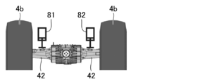
- FIG. 5 is a schematic view showing a first example of the oscillating lock mechanism 40.
- the oscillating lock mechanism 40 shown in FIG. 5 has cylinders 81 and 82.
- the cylinder 81 is arranged to face the portion of the rear axle 42 closer to the rear wheel 4b on the left side of the connecting portion 44.
- the cylinder 82 is arranged to face the rear axle 42, which is closer to the rear wheel 4b on the right side of the connecting portion 44.
- FIG. 6 is a schematic view showing a driving state of the oscillating lock mechanism 40 shown in FIG.
- the piston rods of the cylinders 81 and 82 protrude, and the tip of the piston rods comes into contact with the rear axle 42.
- the piston rods of the cylinders 81 and 82 protrude, and the tip of the piston rods comes into contact with the rear axle 42.
- the relative movement of the rear axle 42 with respect to the vehicle body is hindered. In this way, the rear axle 42 is locked so that the rear axle 42 does not roll with respect to the vehicle body.
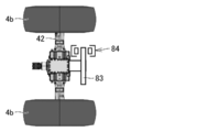
- FIG. 7 is a schematic view showing a second example of the oscillating lock mechanism 40.
- the oscillating lock mechanism 40 shown in FIG. 7 has a brake disc 83 and a brake pad 84.
- the brake disc 83 is fixed to the rear axle 42 and is rotatable with respect to the vehicle body integrally with the rear axle 42.
- the brake disc 83 has a flat plate shape.
- the brake pads 84 are arranged so as to sandwich the flat plate-shaped brake disc 83 in between.
- the brake pad 84 sandwiches the flat plate-shaped brake disc 83 from both sides in the driving state, and regulates the movement of the brake disc 83. Since the brake disc 83 is integrally fixed to the rear axle 42, the relative movement of the rear axle 42 with respect to the vehicle body is hindered. In this way, the rear axle 42 is locked so that the rear axle 42 does not roll with respect to the vehicle body.
- the first processing device 30 shown in FIG. 2 has a function of locking the roll operation of the rear axle 42 with respect to the vehicle body by driving the oscillating lock mechanism 40.
- the functional block of the first processing apparatus 30 having this function will be described below.
- FIG. 8 is a diagram showing a functional block in the first processing device 30.
- the first processing device 30 includes, for example, a vehicle body information detection unit 36, a center of gravity calculation unit 37, a discrimination unit 38, and a command unit 39.
- the vehicle body information detection unit 36 detects the vehicle body information of the wheel loader 1.
- the vehicle body information detection unit 36 includes a vehicle speed detection signal of the wheel loader 1 output from the vehicle speed detection unit 27, a hydraulic pressure detection signal in the boom cylinder 16 output from the first hydraulic detectors 28a and 28b, and a first.
- the detection signal of the inclination angle of the vehicle body output from the IMU66 is acquired.
- the boom angle ⁇ 1, the bucket angle ⁇ 2, the articulating angle, and the inclination angle of the vehicle body may be acquired by analyzing the image of the camera attached to the cab 5. Further, the IMU may be installed in the work machine 3, and the boom angle ⁇ 1 and the bucket angle ⁇ 2 may be acquired from the relativity between the detection result of the IMU of the work machine 3 and the detection result of the IMU 66 of the vehicle body.
- the center of gravity calculation unit 37 calculates the position of the center of gravity of the vehicle body of the wheel loader 1 based on the acquired vehicle body information.
- the center of gravity calculation unit 37 further obtains a vertical straight line, which is a virtual straight line extending in the vertical direction through the center of gravity of the vehicle body.
- the center of gravity calculation unit 37 outputs the obtained vertical line information to the determination unit 38.
- the discrimination unit 38 reads out information related to the specifications of the vehicle body of the wheel loader 1 from the storage unit 30j (FIG. 2). Specifically, the discriminating unit 38 reads out the rotation centers of the left and right front wheels 4a and the center positions of the roll operation of the rear axle 42 with respect to the vehicle body from the storage unit 30j.
- the determination unit 38 derives a region defined from the rotation centers of the left and right front wheels 4a and the center positions of the roll operation of the rear axle 42 based on the information related to the vehicle body specifications of the wheel loader 1 and the articulation angle. To do.
- the determination unit 38 determines the stability of the wheel loader 1 from the positional relationship between this region and the vertical line acquired from the center of gravity calculation unit 37. Based on the determined stability, the determination unit 38 determines whether or not to lock the roll operation of the rear axle 42.
- the determination unit 38 outputs the determination result to the command unit 39.
- the command unit 39 When the command unit 39 obtains the determination result of locking the roll operation of the rear axle 42 from the determination unit 38, the command unit 39 outputs a control signal for driving the oscillate lock mechanism 40 to the oscillate lock mechanism 40.
- FIG. 9 is a flow chart showing a flow of processing for locking the roll operation of the rear axle 42.
- the vehicle body information is detected in step S1.
- the first processing device 30, specifically, the vehicle body information detection unit 36 detects the vehicle body information of the wheel loader 1.
- FIG. 10 is a side view of the wheel loader 1 showing an example of vehicle body information.
- the vehicle body information includes the posture of the work machine 3.
- the boom 14 is located upward as compared with FIG.
- the boom reference line A is above the horizon H in the posture shown in FIG.
- the boom angle ⁇ 1 takes a positive value.
- the bucket 6 is moved in the dump direction as compared with FIG.
- the bucket angle ⁇ 2 takes a negative value.
- the vehicle body information detection unit 36 acquires a detection signal of the boom angle ⁇ 1 from the first angle detector 29.
- the vehicle body information detection unit 36 acquires a detection signal of the bucket angle ⁇ 2 from the second angle detector 48. From the boom angle ⁇ 1 and the bucket angle ⁇ 2, the posture of the working machine 3 can be obtained.
- the posture of the work machine 3 affects the position of the center of gravity of the vehicle body of the wheel loader 1. In the posture in which the boom 14 shown in FIG. 10 is lifted, the center of gravity of the vehicle body is located upward as compared with the posture shown in FIG.
- FIG. 11 is a side view of the wheel loader 1 showing an example of vehicle body information.
- the vehicle body information includes the state of the load L loaded on the work machine 3.
- the boom angle ⁇ 1 has a positive value and the bucket angle ⁇ 2 has a negative value.
- the load L is loaded on the bucket 6.
- the vehicle body information detection unit 36 acquires a detection signal of the boom angle ⁇ 1 from the first angle detector 29.
- the vehicle body information detection unit 36 acquires a detection signal of the bucket angle ⁇ 2 from the second angle detector 48.
- the vehicle body information detection unit 36 acquires detection signals for the head pressure and bottom pressure of the boom cylinder 16 from the first oil pressure detectors 28a and 28b.
- the weight of the load L loaded on the work machine 3 can be obtained from the boom angle ⁇ 1, the bucket angle ⁇ 2, and the head pressure and bottom pressure of the boom cylinder 16.
- the weight of the load L loaded on the work machine 3 and the posture of the work machine 3 loaded with the load L affect the position of the center of gravity of the vehicle body of the wheel loader 1.
- the center of gravity of the vehicle body is located above as compared with FIG.
- FIG. 12 is a plan view of the wheel loader 1 showing an example of vehicle body information.
- the vehicle body information includes the articulated angle.
- the front frame 2a is bent with respect to the rear frame 2b.
- the vehicle body information detection unit 36 acquires an articulated angle detection signal from the articulated angle sensor 61.
- the articulating angle affects the region defined by the center of rotation of the left and right front wheels 4a and the center position of the roll operation of the rear axle 42.
- the shape of the region in a plan view is an isosceles triangle when the wheel loader 1 travels straight, but is an isosceles triangle in the bent posture shown in FIG.
- the articulating angle also affects the position of the center of gravity of the vehicle body of the wheel loader 1.
- FIG. 13 is a view of the wheel loader 1 viewed from the rear, showing an example of vehicle body information.
- the vehicle body information includes the inclination of the wheel loader 1 with respect to the vertical direction of the vehicle body.
- the ground GL on which the wheel loader 1 shown in FIG. 13 is traveling is inclined, so that the vehicle body of the wheel loader 1 is inclined with respect to the vertical direction.
- the vehicle body information detection unit 36 acquires a detection signal of the inclination angle of the vehicle body from the IMU 66.
- the tilt angle of the vehicle body affects the inclination of the vertical line with respect to the vertical direction of the vehicle body.
- the vertical straight line which is a virtual straight line extending in the vertical direction through the center of gravity of the vehicle body of the wheel loader 1, extends along the vertical direction of the vehicle body when the wheel loader 1 is traveling on a flat road surface. When the wheel loader 1 is traveling on an inclined surface as shown in FIG. 13, the vertical straight line extends in a direction in which the vehicle body is inclined with respect to the vertical direction.
- the vehicle body information includes the vehicle speed of the wheel loader 1.
- the vehicle body information detection unit 36 acquires a vehicle speed detection signal from the vehicle speed detection unit 27. In particular, when traveling on an inclined surface as shown in FIG. 13, if the vehicle speed is high, the stability of the posture of the wheel loader 1 is lowered.
- the first processing device 30 obtains the position of the center of gravity of the vehicle body of the wheel loader 1 from the vehicle body information detected in the previous step S1, and passes through the center of gravity in the vertical direction. Find the vertical straight line that is a virtual straight line that extends.
- the first processing device 30 is also defined with information related to the specifications of the vehicle body of the wheel loader 1, specifically, the rotation centers of the left and right front wheels 4a and the center position of the roll operation of the rear axle 42 with respect to the vehicle body as vertices. Derivation of the region.
- the first processing device 30 further calculates the positional relationship between the region and the vertical line.
- step S3 the first processing device 30 determines the stability of the wheel loader 1. Specifically, the first processing device 30 determines whether or not the inclination of the vehicle body with respect to the vertical direction is increased by oscillating the wheel loader 1 by its own weight.
- FIG. 14 is a diagram showing a vertical line of the wheel loader 1 traveling on an inclined surface.
- FIG. 14 shows a view of the wheel loader 1 as viewed from the rear, similar to that of FIG.
- the ground GL on which the wheel loader 1 travels is inclined sideways.
- the vertical line g shown in FIG. 14 extends in a direction inclined with respect to a direction orthogonal to the ground GL.
- the vertical line g extends at an angle with respect to the vertical direction of the vehicle body of the wheel loader 1.
- FIG. 15 is a diagram showing the positional relationship between the regions R11 and R12 and the vertical line g in an oscillating state.
- the region R11 shown in FIG. 15 is defined by three vertices P1, P2 and P3.
- the apex P1 is the center of rotation of the right front wheel 4a.
- the apex P1 indicates the center of the hub at the right end of the front axle 41.
- the apex P2 is the center of rotation of the left front wheel 4a.
- the apex P2 indicates the center of the leftmost hub of the front axle 41.
- the apex P3 indicates the central position of the rear axle 42 in the left-right direction.
- the apex P3 indicates the position of the connecting portion 44 (FIG. 2) between the rear propeller shaft 43 and the rear axle 42.
- the apex P3 indicates the center position of the roll operation of the rear axle 42 with respect to the vehicle body.
- FIG. 15 shows the wheel loader 1 in a straight running posture, at which time the region R11 has the shape of an isosceles triangle.
- the region R11 becomes an isosceles triangle.
- the vertical straight line g since the vertical straight line g is inclined with respect to the vertical direction of the vehicle body, the vertical straight line g does not intersect the region R11 on the plane where the region R11 is defined.
- the vertical line g is outside the region R11. Since the vehicle body is inclined to the left, the vertical line g is outside the left side of the region R11.
- the discriminating unit 38 has the rear axle 42 with respect to the vehicle body due to the weight of the vehicle body.
- the vehicle body rotates relative to the rear axle 42 in the counterclockwise direction by its own weight, the vehicle body tilts more with respect to the ground GL.
- the posture of the vehicle body becomes unstable.
- step S4 the process proceeds to step S4, and the roll operation of the rear axle 42 is locked.
- a control signal for driving the oscillating lock mechanism 40 is output from the command unit 39 of the first processing device 30 to the oscillating lock mechanism 40.
- the roll operation of the rear axle 42 is locked by driving the oscillating lock mechanism 40 that receives the control signal.
- FIG. 16 is a first diagram showing the positional relationship between the region R21 and the vertical line g in the oscillated lock state. When the roll motion of the rear axle 42 is locked, the region R21 shown in FIG. 16 is defined.
- Region R21 is defined by four vertices P11, P12, P13 and P14.
- the apex P11 is the center of rotation of the right front wheel 4a.
- the apex P11 indicates the center of the hub at the right end of the front axle 41.
- the apex P12 is the center of rotation of the left front wheel 4a.
- the apex P12 indicates the center of the leftmost hub of the front axle 41.
- the apex P13 is the center of rotation of the right rear wheel 4b.
- the apex P13 indicates the center of the hub (rear wheel mounting portion 46, FIG. 4) at the right end of the rear axle 42.
- the apex P14 is the center of rotation of the left rear wheel 4b.
- the apex P14 indicates the center of the leftmost hub (rear wheel mounting portion 46, FIG. 4) of the rear axle 42.
- the region R21 has a rectangular shape.
- the vertical line g intersects the region R21.
- the vertical line g is inside the region R21.
- FIG. 17 is a second diagram showing the positional relationship between the region R22 and the vertical line g in the oscillated lock state.
- FIG. 17 shows a region R22 defined when the left rear wheel 4b is in contact with the ground while the right rear wheel 4b is not in contact with the ground.
- the region R11 described with reference to FIG. 16 is a region defined when both the left and right rear wheels 4b are in contact with the ground.
- Region R22 is defined by three vertices P11, P12 and P14. Region R22 has the shape of a right triangle. As shown in FIG. 17, in the plane where the region R22 is defined, the vertical line g intersects the region R22. The vertical line g is inside the region R22.
- step S3 even if the vehicle body is not tilted and the rear axle 42 does not roll with respect to the vehicle body, or even if the rear axle 42 rolls with respect to the vehicle body, the vehicle body is tilted. If it is determined that the vehicle body is not tilted enough to increase (NO in step S3), that is, if it is determined that the stability of the wheel loader 1 is sufficiently high, the process proceeds to step S5. In the process of step S5, the control signal is not output from the command unit 39 to the oscillating lock mechanism 40, and the roll operation of the rear axle 42 is not locked and remains in an oscillating state. Then, the process ends.
- the area R12 shown by the broken line is defined inside the area R11 shown by the solid line.
- Region R12 is defined by three vertices P4, P5 and P6.
- the vertices P4 and P5 are located behind the front axle 41.
- the apex P6 is located in front of the rear axle 42.
- the apex P4 is located inside the vehicle body with respect to the apex P1.
- the apex P5 is located inside the vehicle body with respect to the apex P2.
- the apex P6 is located inside the vehicle body with respect to the apex P3.
- the region R12 is an isosceles triangle similar to the region R11.
- the isosceles triangle forming the region R12 has a shorter base and height than the isosceles triangle forming the region R11, and therefore has a smaller area.
- the region R12 can be set as a region in consideration of a sensor error or the like with respect to the region R11.
- the region R11 was set based on the information related to the specifications of the vehicle body, the region R12 was set in consideration of the error with respect to the region R11, and it was determined that the vertical line g did not intersect the region R12 and was outside the region R12. In some cases, it is possible to lock the roll operation of the rear axle 42. By doing so, it is possible to more reliably prevent an increase in the inclination of the vehicle body.
- the wheel loader 1 includes a rear axle 42 and a first processing device 30.
- the rear axle 42 can roll with respect to an axis extending in the front-rear direction of the vehicle body.
- the first processing device 30 has a region R11 defined by the vertices P1 and P2 which are the rotation centers of the left and right front wheels 4a and the vertices P3 which is the center of the roll operation of the rear axle 42.
- the first processing device 30 sets a vertical straight line g, which is a virtual straight line extending in the vertical direction through the center of gravity of the vehicle body.
- the first processing device 30 acquires the stability of the center of gravity of the vehicle body of the wheel loader 1 from the positional relationship between the region R11 and the vertical line g, and based on the acquired stability, the roll operation of the rear axle 42 with respect to the vehicle body. To control.
- the first processing device 30 controls the roll operation of the rear axle 42.
- the roll operation of the rear axle 42 it is possible to suppress an increase in the inclination of the wheel loader 1 with respect to the ground. Therefore, it is possible to prevent the wheel loader 1 having the rear axle 42 that can roll with respect to the vehicle body from tipping over.
- the first processing device 30 obtains the vertical line g in consideration of the inclination of the vehicle body with respect to the vertical direction. By obtaining the vertical line g in this way, it is possible to more accurately determine whether or not it is necessary to control the roll operation of the rear axle 42 based on the positional relationship between the region R11 and the vertical line g.
- the first processing device 30 obtains the position of the center of gravity of the vehicle body in consideration of the posture of the working machine 3 and the state of the load L loaded on the working machine 3. By obtaining the position of the center of gravity in this way, it is possible to more accurately determine whether or not it is necessary to control the roll operation of the rear axle 42 based on the positional relationship between the region R11 and the vertical line g.
- the first processing device 30 calculates the region R11 from the angle formed by the front frame 2a and the rear frame 2b. By calculating the region R11 in this way, it is possible to more accurately determine whether or not the roll operation of the rear axle 42 needs to be controlled based on the positional relationship between the region R11 and the vertical line g.
- the first processing device 30 can obtain the position of the center of gravity of the vehicle body by using the articulated angle, and can calculate the region R11 by using the articulated angle. In this way, the region R11 and the vertical line can be calculated. Whether or not it is necessary to control the roll operation of the rear axle 42 based on the positional relationship with g can be determined more accurately.
- the wheel loader 1 further includes an oscillating lock mechanism 40 that locks the roll operation of the rear axle 42.
- the first processing device 30 can easily execute the control for locking the roll operation of the rear axle 42.
- the oscillating lock mechanism 40 is used. Drive.
- the wheel loader 1 provided with the rear axle 42 capable of rolling with respect to the vehicle body can be prevented from tipping over. Can be prevented.
- the first processing device 30 drives the oscillate lock mechanism 40 when the vertical line g does not intersect the region R11. Thereby, it is possible to more accurately determine whether or not the oscillating lock mechanism 40 needs to be driven based on the positional relationship between the vertical line g and the region R11.
- the oscillating lock mechanism 40 for fixing the rear axle 42 is provided, and when the rear axle 42 rolls with respect to the vehicle body, the inclination of the vehicle body with respect to the ground may increase.
- a configuration in which the 42 is locked to suppress an increase in the inclination of the vehicle body has been described.
- a mechanism having cylinders 81, 82 shown in FIGS. 5 and 6 may be applied to rotationally drive the rear axle 42.
- the piston rod of the cylinder 81 drives the rear axle 42 to be pressed, while the cylinder 82 is controlled so as not to be driven. May be good.
- the region R11 in an oscillating state is defined from the rotation centers of the left and right front wheels 4a and the center position of the roll operation of the rear axle 42 with respect to the vehicle body.
- the apex defining the region R11 in the rear axle 42 is not limited to the apex P3 which is the center position of the roll operation, and may be set at an arbitrary position of the rear axle 42.
- the vertices of the region R11 may be set at both ends of the rear axle 42.
- the vertices of the region R11 may be set on either or both of the left and right rear wheels 4b.
- the rear axle 42 extending in the left-right direction may form one side of the region R11.
- the apex defining the region R11 in the front axle 41 is not limited to the left and right front wheels 4a, and may be set at an arbitrary position of the front axle 41.
- the wheel loader 1 has been described as an example of the work machine.
- the idea of the embodiment may be applied not only to the wheel loader 1 but also to any other work machine capable of oscillating the rear wheels.
- 1 wheel loader 2 body frame, 2a front frame, 2b rear frame, 3 work machine, 4 traveling device, 4a front wheel, 4b rear wheel, 5 cab, 6 bucket, 14 boom, 20 engine, 27 vehicle speed detector, 28a, 28b 1st oil pressure detector, 29 1st angle detector, 30 1st processing device, 36 vehicle body information detection unit, 37 center of gravity calculation unit, 38 discrimination unit, 39 command unit, 40 oscillating lock mechanism, 41 front axle, 42 rear Axle, 43 rear propeller shaft, 44 connecting part, 46 rear wheel mounting part, 48 second angle detector, 61 articulated angle sensor, 81, 82 cylinder, 83 brake disc, 84 brake pad, A boom reference line, AR both Arrow, B bucket reference line, GL ground, H horizon, L load, P1, P2, P3, P4, P5, P6, P11, P12, P13, P14 apex, R11, R12, R21, R22 area, g vertical line.
Landscapes
- Engineering & Computer Science (AREA)
- Mining & Mineral Resources (AREA)
- Civil Engineering (AREA)
- General Engineering & Computer Science (AREA)
- Structural Engineering (AREA)
- Mechanical Engineering (AREA)
- Chemical & Material Sciences (AREA)
- Combustion & Propulsion (AREA)
- Transportation (AREA)
- Operation Control Of Excavators (AREA)
- Component Parts Of Construction Machinery (AREA)
- Arrangement And Driving Of Transmission Devices (AREA)
- Vehicle Body Suspensions (AREA)
Abstract
To prevent a work machine from tipping over. The work machine comprises: a vehicle body; a rear axle attached to the vehicle body so as to be rollable with respect to a shaft extending in a front-rear direction of the vehicle body; and a controller. The controller acquires a stability degree of the center of gravity of the vehicle body and controls the rolling motion of the rear axle with respect to the vehicle body on the basis of the stability degree.
Description
本開示は、作業機械に関する。
This disclosure relates to work machines.
特開平5-86636号公報(特許文献1)には、車体の回転モーメントと作業機の回転モーメントとを合成して得られた車両を接地させる方向の回転モーメントが閾値以下になると、作業機の姿勢を調整する、作業車両が開示されている。この文献には、かかる構成により、作業車両が傾斜地を走行する場合の転倒を未然に防止すると記載されている。
According to Japanese Patent Application Laid-Open No. 5-86636 (Patent Document 1), when the rotational moment in the direction of grounding the vehicle obtained by combining the rotational moment of the vehicle body and the rotational moment of the working machine becomes equal to or less than the threshold value, the working machine A work vehicle that adjusts the posture is disclosed. This document describes that such a configuration prevents a work vehicle from tipping over when traveling on a slope.
ホイールローダなどの作業機械の場合、地面の凹凸に応じて後輪が左右に傾くリアアクスルオシレート機構を備えることで、前輪および後輪の四輪が常に接地して、駆動力を確実に地面に伝えることを可能としている。
In the case of work machines such as wheel loaders, by providing a rear axle oscillating mechanism that tilts the rear wheels to the left and right according to the unevenness of the ground, the four wheels of the front and rear wheels are always in contact with the ground, ensuring that the driving force is on the ground. It is possible to convey.
上記文献には、リアアクスルが車体に対して回転しない作業車両が開示されており、オシレート可能な作業機械の転倒の防止については考慮されていない。
The above document discloses a work vehicle in which the rear axle does not rotate with respect to the vehicle body, and does not consider prevention of the work machine that can be oscillated from tipping over.
本開示では、車体に対してロール動作可能なリアアクスルを備える作業機械の転倒を未然に防止できる技術が提供される。
The present disclosure provides a technique that can prevent a work machine equipped with a rear axle that can roll with respect to the vehicle body from tipping over.
本開示に従うと、車体と、車体の前後方向に延びる軸に対しロール動作可能に車体に取り付けられたリアアクスルとを備える、作業機械が提供される。作業機械は、コントローラを備えている。コントローラは、車体の重心の安定度を取得し、重心の安定度に基づきリアアクスルの車体に対するロール動作を制御する。
According to the present disclosure, a work machine including a vehicle body and a rear axle attached to the vehicle body so as to be roll-operable with respect to an axis extending in the front-rear direction of the vehicle body is provided. The work machine is equipped with a controller. The controller acquires the stability of the center of gravity of the vehicle body and controls the roll operation of the rear axle with respect to the vehicle body based on the stability of the center of gravity.
本開示に従えば、車体に対してロール動作可能なリアアクスルを備える作業機械の転倒を未然に防止することができる。
According to the present disclosure, it is possible to prevent a work machine equipped with a rear axle that can roll with respect to the vehicle body from tipping over.
以下、実施形態について図に基づいて説明する。以下の説明では、同一部品には、同一の符号を付している。それらの名称および機能も同じである。したがって、それらについての詳細な説明は繰り返さない。
Hereinafter, the embodiment will be described with reference to the figure. In the following description, the same parts are designated by the same reference numerals. Their names and functions are the same. Therefore, the detailed description of them will not be repeated.
<全体構成>
実施形態においては、作業機械の一例としてホイールローダ1について説明する。図1は、実施形態に基づく作業機械の一例としてのホイールローダ1の側面図である。 <Overall configuration>
In the embodiment, thewheel loader 1 will be described as an example of the working machine. FIG. 1 is a side view of a wheel loader 1 as an example of a work machine based on an embodiment.
実施形態においては、作業機械の一例としてホイールローダ1について説明する。図1は、実施形態に基づく作業機械の一例としてのホイールローダ1の側面図である。 <Overall configuration>
In the embodiment, the
図1に示されるように、ホイールローダ1は、車体フレーム2と、作業機3と、走行装置4と、キャブ5とを備えている。車体フレーム2、キャブ5などからホイールローダ1の車体(作業機械本体)が構成されている。ホイールローダ1の車体には、作業機3および走行装置4が取り付けられている。
As shown in FIG. 1, the wheel loader 1 includes a vehicle body frame 2, a working machine 3, a traveling device 4, and a cab 5. The vehicle body (working machine body) of the wheel loader 1 is composed of the vehicle body frame 2, the cab 5, and the like. A work machine 3 and a traveling device 4 are attached to the vehicle body of the wheel loader 1.
走行装置4は、ホイールローダ1の車体を走行させるものであり、走行輪4a、4bを含んでいる。ホイールローダ1は、走行輪4a、4bが回転駆動されることにより自走可能であり、作業機3を用いて所望の作業を行うことができる。
The traveling device 4 travels the vehicle body of the wheel loader 1, and includes traveling wheels 4a and 4b. The wheel loader 1 can self-propell by rotating the traveling wheels 4a and 4b, and can perform a desired work by using the working machine 3.
車体フレーム2は、前フレーム2aと後フレーム2bとを含んでいる。前フレーム2aと後フレーム2bとは、互いに左右方向に回動可能に取り付けられている。前フレーム2aと後フレーム2bとに亘って、一対のステアリングシリンダ11が取り付けられている。ステアリングシリンダ11は、油圧シリンダである。ステアリングシリンダ11がステアリングポンプ(図示せず)からの作動油によって伸縮することによって、ホイールローダ1の進行方向が左右に変更される。
The body frame 2 includes a front frame 2a and a rear frame 2b. The front frame 2a and the rear frame 2b are rotatably attached to each other in the left-right direction. A pair of steering cylinders 11 are attached to the front frame 2a and the rear frame 2b. The steering cylinder 11 is a hydraulic cylinder. The traveling direction of the wheel loader 1 is changed to the left and right by expanding and contracting the steering cylinder 11 with hydraulic oil from a steering pump (not shown).
本明細書中において、ホイールローダ1が直進走行する方向を、ホイールローダ1の前後方向という。ホイールローダ1の前後方向において、車体フレーム2に対して作業機3が配置されている側を前方向とし、前方向と反対側を後方向とする。ホイールローダ1の左右方向とは、平坦な地面上にあるホイールローダ1を平面視したときに前後方向と直交する方向である。前方向を見て左右方向の右側、左側が、それぞれ右方向、左方向である。ホイールローダ1の上下方向とは、前後方向および左右方向によって定められる平面に直交する方向である。上下方向において地面のある側が下側、空のある側が上側である。
In this specification, the direction in which the wheel loader 1 travels straight is referred to as the front-rear direction of the wheel loader 1. In the front-rear direction of the wheel loader 1, the side on which the work machine 3 is arranged with respect to the vehicle body frame 2 is the front direction, and the side opposite to the front direction is the rear direction. The left-right direction of the wheel loader 1 is a direction orthogonal to the front-rear direction when the wheel loader 1 on a flat ground is viewed in a plan view. Looking forward, the right and left sides of the left and right directions are the right direction and the left direction, respectively. The vertical direction of the wheel loader 1 is a direction orthogonal to the plane defined by the front-rear direction and the left-right direction. In the vertical direction, the side with the ground is the lower side, and the side with the sky is the upper side.
前フレーム2aには、作業機3および左右一対の走行輪(前輪)4aが取り付けられている。作業機3は、車体の前方に配設されている。作業機3は、作業機ポンプ25(図2参照)からの作動油によって駆動される。作業機ポンプ25は、エンジン20により駆動され、吐出する作動油によって作業機3を作動させる油圧ポンプである。作業機3は、ブーム14と、作業具であるバケット6とを含んでいる。バケット6は、作業機3の先端に配置されている。バケット6は、ブーム14の先端に着脱可能に装着されたアタッチメントの一例である。作業の種類に応じて、アタッチメントが、グラップル、フォーク、またはプラウなどに付け替えられる。
A work machine 3 and a pair of left and right traveling wheels (front wheels) 4a are attached to the front frame 2a. The working machine 3 is arranged in front of the vehicle body. The work machine 3 is driven by hydraulic oil from the work machine pump 25 (see FIG. 2). The work machine pump 25 is a hydraulic pump that is driven by the engine 20 and operates the work machine 3 by the hydraulic oil discharged. The work machine 3 includes a boom 14 and a bucket 6 which is a work tool. The bucket 6 is arranged at the tip of the working machine 3. The bucket 6 is an example of an attachment detachably attached to the tip of the boom 14. Depending on the type of work, the attachment can be replaced with a grapple, fork, or plow.
ブーム14の基端部は、ブームピン9によって前フレーム2aに回転自在に取付けられている。バケット6は、ブーム14の先端に位置するバケットピン17によって、回転自在にブーム14に取付けられている。
The base end portion of the boom 14 is rotatably attached to the front frame 2a by the boom pin 9. The bucket 6 is rotatably attached to the boom 14 by a bucket pin 17 located at the tip of the boom 14.
前フレーム2aとブーム14とは、一対のブームシリンダ16により連結されている。ブームシリンダ16は、油圧シリンダである。ブームシリンダ16の基端は、前フレーム2aに取り付けられている。ブームシリンダ16の先端は、ブーム14に取り付けられている。ブームシリンダ16が作業機ポンプ25(図2参照)からの作動油によって伸縮することによって、ブーム14が昇降する。ブームシリンダ16は、ブーム14を、ブームピン9を中心として上下に回転駆動する。
The front frame 2a and the boom 14 are connected by a pair of boom cylinders 16. The boom cylinder 16 is a hydraulic cylinder. The base end of the boom cylinder 16 is attached to the front frame 2a. The tip of the boom cylinder 16 is attached to the boom 14. The boom 14 moves up and down as the boom cylinder 16 expands and contracts due to the hydraulic oil from the work equipment pump 25 (see FIG. 2). The boom cylinder 16 rotationally drives the boom 14 up and down around the boom pin 9.
作業機3は、ベルクランク18と、バケットシリンダ19と、リンク15とをさらに含んでいる。ベルクランク18は、ブーム14のほぼ中央に位置する支持ピン18aによって、ブーム14に回転自在に支持されている。バケットシリンダ19は、ベルクランク18と前フレーム2aとを連結している。リンク15は、ベルクランク18の先端部に設けられた連結ピン18cに連結されている。リンク15は、ベルクランク18とバケット6とを連結している。
The working machine 3 further includes a bell crank 18, a bucket cylinder 19, and a link 15. The bell crank 18 is rotatably supported by the boom 14 by a support pin 18a located substantially in the center of the boom 14. The bucket cylinder 19 connects the bell crank 18 and the front frame 2a. The link 15 is connected to a connecting pin 18c provided at the tip of the bell crank 18. The link 15 connects the bell crank 18 and the bucket 6.
バケットシリンダ19は、油圧シリンダであり作業具シリンダである。バケットシリンダ19の基端は、前フレーム2aに取り付けられている。バケットシリンダ19の先端は、ベルクランク18の基端部に設けられた連結ピン18bに取り付けられている。バケットシリンダ19が作業機ポンプ25(図2参照)からの作動油によって伸縮することによって、バケット6が上下に回動する。バケットシリンダ19は、バケット6を、バケットピン17を中心として回転駆動する。
The bucket cylinder 19 is a hydraulic cylinder and a work tool cylinder. The base end of the bucket cylinder 19 is attached to the front frame 2a. The tip of the bucket cylinder 19 is attached to a connecting pin 18b provided at the base end of the bell crank 18. The bucket cylinder 19 expands and contracts due to the hydraulic oil from the work equipment pump 25 (see FIG. 2), so that the bucket 6 rotates up and down. The bucket cylinder 19 rotationally drives the bucket 6 around the bucket pin 17.
後フレーム2bには、キャブ5および左右一対の走行輪(後輪)4bが取り付けられている。キャブ5は、ブーム14の後方に配置されている。キャブ5は、車体フレーム2上に載置されている。キャブ5内には、オペレータが着座するシートおよび後述する操作装置などが配置されている。
A cab 5 and a pair of left and right traveling wheels (rear wheels) 4b are attached to the rear frame 2b. The cab 5 is located behind the boom 14. The cab 5 is mounted on the vehicle body frame 2. In the cab 5, a seat on which the operator sits and an operation device described later are arranged.
キャブ5内には、IMU(Inertial Measurement Unit)66が配置されている。IMU66は、車体フレーム2の傾きを検出する。IMU66は、車体フレーム2の前後方向および左右方向に対する傾斜角を検出する。IMU66は、ホイールローダ1の車体の鉛直方向に対する傾きを検出する。
An IMU (Inertial Measurement Unit) 66 is arranged in the cab 5. The IMU 66 detects the inclination of the vehicle body frame 2. The IMU 66 detects the inclination angle of the vehicle body frame 2 with respect to the front-rear direction and the left-right direction. The IMU 66 detects the inclination of the wheel loader 1 with respect to the vertical direction of the vehicle body.
キャブ5の後方に、エンジンフード7が配置されている。エンジンフード7は、エンジン20(図2)などを収納する収納空間の上方および両側方を覆っている。エンジンフード7の上面から、エアクリーナ12および排気管13が、上方に突出している。
The engine hood 7 is located behind the cab 5. The engine hood 7 covers the upper side and both sides of the storage space for storing the engine 20 (FIG. 2) and the like. The air cleaner 12 and the exhaust pipe 13 project upward from the upper surface of the engine hood 7.
背面グリル8は、エンジンフード7の後方に配置されている。背面グリル8は、上記の収納空間を後方から覆っている。背面グリル8の後面には、収納空間の内部と外部とを連通する吸気口が形成されている。この吸気口を通過して、収納空間の内部に空気が供給される。
The rear grill 8 is arranged behind the engine hood 7. The rear grill 8 covers the storage space from the rear. An intake port that communicates the inside and the outside of the storage space is formed on the rear surface of the rear grill 8. Air is supplied to the inside of the storage space through this intake port.
図2は、実施形態に従うホイールローダ1を含む全体システムの構成を示す概略ブロック図である。
FIG. 2 is a schematic block diagram showing the configuration of the entire system including the wheel loader 1 according to the embodiment.
ホイールローダ1は、エンジン20、動力取り出し部22、動力伝達機構23、シリンダ駆動部24、第一角度検出器29、第二角度検出器48、回動機構60および第1処理装置30(コントローラ)を備えている。
The wheel loader 1 includes an engine 20, a power extraction unit 22, a power transmission mechanism 23, a cylinder drive unit 24, a first angle detector 29, a second angle detector 48, a rotation mechanism 60, and a first processing device 30 (controller). It has.
エンジン20は、たとえばディーゼルエンジンである。エンジン20は、エンジンフード7(図1)に覆われた収納空間内に収納されている。エンジン20の出力は、エンジン20のシリンダ内に噴射する燃料量を調整することにより制御される。エンジン20には、回転センサ32が設けられている。回転センサ32は、エンジン20内部の回転軸の回転数を検出する。回転センサ32は、回転数を示す検出信号を第1処理装置30に出力する。
The engine 20 is, for example, a diesel engine. The engine 20 is housed in a storage space covered with an engine hood 7 (FIG. 1). The output of the engine 20 is controlled by adjusting the amount of fuel injected into the cylinder of the engine 20. The engine 20 is provided with a rotation sensor 32. The rotation sensor 32 detects the rotation speed of the rotation shaft inside the engine 20. The rotation sensor 32 outputs a detection signal indicating the rotation speed to the first processing device 30.
動力取り出し部22は、エンジン20の出力を、動力伝達機構23とシリンダ駆動部24とに振り分ける装置である。動力伝達機構23は、エンジン20からの駆動力を前輪4aおよび後輪4bに伝達する機構であり、たとえばトランスミッションである。ホイールローダ1においては、前フレーム2aに取り付けられた前輪4aと、後フレーム2bに取り付けられた後輪4bとの両方が、駆動力を受けてホイールローダ1を走行させる駆動輪を構成している。
The power take-out unit 22 is a device that distributes the output of the engine 20 to the power transmission mechanism 23 and the cylinder drive unit 24. The power transmission mechanism 23 is a mechanism that transmits the driving force from the engine 20 to the front wheels 4a and the rear wheels 4b, and is, for example, a transmission. In the wheel loader 1, both the front wheels 4a attached to the front frame 2a and the rear wheels 4b attached to the rear frame 2b form driving wheels for running the wheel loader 1 by receiving a driving force. ..
動力伝達機構23は、入力軸21の回転を変速して出力軸23aに出力する。動力伝達機構23の出力軸23aには、ホイールローダ1の車速を検出するための車速検出部27が取り付けられている。ホイールローダ1は、車速検出部27を含んでいる。
The power transmission mechanism 23 shifts the rotation of the input shaft 21 and outputs it to the output shaft 23a. A vehicle speed detection unit 27 for detecting the vehicle speed of the wheel loader 1 is attached to the output shaft 23a of the power transmission mechanism 23. The wheel loader 1 includes a vehicle speed detection unit 27.
車速検出部27はたとえば車速センサである。車速検出部27は、出力軸23aの回転速度を検出することにより、走行装置4(図1)によるホイールローダ1の移動速度を検出する。車速検出部27は、出力軸23aの回転速度を検出するための回転センサとして機能する。車速検出部27は、走行装置4による移動を検出する移動検出器として機能する。車速検出部27は、ホイールローダ1の車速を示す検出信号を第1処理装置30に出力する。
The vehicle speed detection unit 27 is, for example, a vehicle speed sensor. The vehicle speed detection unit 27 detects the moving speed of the wheel loader 1 by the traveling device 4 (FIG. 1) by detecting the rotation speed of the output shaft 23a. The vehicle speed detection unit 27 functions as a rotation sensor for detecting the rotation speed of the output shaft 23a. The vehicle speed detection unit 27 functions as a movement detector that detects movement by the traveling device 4. The vehicle speed detection unit 27 outputs a detection signal indicating the vehicle speed of the wheel loader 1 to the first processing device 30.
出力軸23aに、フロントアクスル41が接続されている。エンジン20の発生する駆動力は、フロントアクスル41に伝達される。フロントアクスル41の両端に、左右の前輪4aが取り付けられている。フロントアクスル41から、左右一対の前輪4aに、駆動力が伝達される。フロントアクスル41は、前フレーム2aに支持されている。前輪4aは、フロントアクスル41を介して、ホイールローダ1の車体の一部を構成する前フレーム2aに、前フレーム2aに対して回転可能に取り付けられている。
The front axle 41 is connected to the output shaft 23a. The driving force generated by the engine 20 is transmitted to the front axle 41. Left and right front wheels 4a are attached to both ends of the front axle 41. The driving force is transmitted from the front axle 41 to the pair of left and right front wheels 4a. The front axle 41 is supported by the front frame 2a. The front wheels 4a are rotatably attached to the front frame 2a forming a part of the vehicle body of the wheel loader 1 via the front axle 41 with respect to the front frame 2a.
回動機構60は、前フレーム2aと後フレーム2bとを回動可能に連結している。後フレーム2bに対する前フレーム2aの回動は、前フレーム2aと後フレーム2bとの間に連結されたアーティキュレートシリンダを伸縮させることで行われる。前フレーム2aは、後フレーム2bに対して屈曲可能である。前フレーム2aを後フレーム2bに対して屈曲させる(アーティキュレートさせる)ことで、前輪4aと後輪4bとの内輪差を小さくして、ホイールローダ1の旋回時の旋回半径を小さくすることが可能である。
The rotation mechanism 60 rotatably connects the front frame 2a and the rear frame 2b. The rotation of the front frame 2a with respect to the rear frame 2b is performed by expanding and contracting the articulated cylinder connected between the front frame 2a and the rear frame 2b. The front frame 2a is bendable with respect to the rear frame 2b. By bending (articulating) the front frame 2a with respect to the rear frame 2b, it is possible to reduce the inner ring difference between the front wheels 4a and the rear wheels 4b and reduce the turning radius of the wheel loader 1 when turning. Is.
回動機構60には、アーティキュレート角度センサ61が設けられている。アーティキュレート角度センサ61は、前フレーム2aと後フレーム2bとのなす角度であるアーティキュレート角度を検出する。アーティキュレート角度センサ61は、アーティキュレート角度を示す検出信号を第1処理装置30に出力する。
The rotating mechanism 60 is provided with an articulated angle sensor 61. The articulated angle sensor 61 detects an articulated angle, which is an angle formed by the front frame 2a and the rear frame 2b. The articulated angle sensor 61 outputs a detection signal indicating the articulated angle to the first processing device 30.
出力軸23aに、リアプロペラシャフト43が接続されている。リアプロペラシャフト43の後端に、連結部44が設けられている。連結部44に、リアアクスル42が接続されている。リアアクスル42は、リアプロペラシャフト43を介して、出力軸23aに接続されている。エンジン20の発生する駆動力は、リアアクスル42に伝達される。リアアクスル42の両端に、左右の後輪4bが取り付けられている。リアアクスル42から、左右一対の後輪4bに、駆動力が伝達される。リアアクスル42は、後フレーム2bに支持されている。後輪4bは、リアアクスル42を介して、ホイールローダ1の車体の一部を構成する後フレーム2bに、後フレーム2bに対して回転可能に取り付けられている。
The rear propeller shaft 43 is connected to the output shaft 23a. A connecting portion 44 is provided at the rear end of the rear propeller shaft 43. The rear axle 42 is connected to the connecting portion 44. The rear axle 42 is connected to the output shaft 23a via the rear propeller shaft 43. The driving force generated by the engine 20 is transmitted to the rear axle 42. Left and right rear wheels 4b are attached to both ends of the rear axle 42. The driving force is transmitted from the rear axle 42 to the pair of left and right rear wheels 4b. The rear axle 42 is supported by the rear frame 2b. The rear wheels 4b are rotatably attached to the rear frame 2b forming a part of the vehicle body of the wheel loader 1 via the rear axle 42 with respect to the rear frame 2b.
図2には、エンジン20の発生する駆動力を前輪4aおよび後輪4bに伝達するための構造の一例が模式的に図示されている。エンジン20から前輪4aおよび後輪4bへの動力伝達構造は、上述した例に限られない。たとえば、動力伝達機構23が、トランスミッションと、駆動力を前後軸に分配するためのトランスファとを有し、トランスファの出力軸の一方端から前輪4aに駆動力が伝達され、トランスファの出力軸の他方端から後輪4bに駆動力が伝達される構造としてもよい。
FIG. 2 schematically illustrates an example of a structure for transmitting the driving force generated by the engine 20 to the front wheels 4a and the rear wheels 4b. The power transmission structure from the engine 20 to the front wheels 4a and the rear wheels 4b is not limited to the above-mentioned example. For example, the power transmission mechanism 23 has a transmission and a transfer for distributing the driving force to the front and rear shafts, and the driving force is transmitted from one end of the output shaft of the transfer to the front wheels 4a, and the other of the output shafts of the transfer. The structure may be such that the driving force is transmitted from the end to the rear wheel 4b.
ホイールローダ1は、リアアクスルオシレート機構を有している。図3は、オシレート可能な状態の後輪4bを示す斜視図である。図3には、左後方から見たホイールローダ1が図示されている。図4は、リアアクスル42の車体に対するロール動作を示す図である。図4には、後方から見たリアアクスル42が図示されている。
The wheel loader 1 has a rear axle oscillating mechanism. FIG. 3 is a perspective view showing the rear wheel 4b in an oscillating state. FIG. 3 shows a wheel loader 1 viewed from the rear left. FIG. 4 is a diagram showing a roll operation of the rear axle 42 with respect to the vehicle body. FIG. 4 shows the rear axle 42 as viewed from the rear.
リアアクスルオシレート機構は、ホイールローダ1が凹凸のある路面または車幅方向に勾配のある路面などを走行する場合において、車体を水平に保つための機構である。リアアクスルオシレート機構を備えるホイールローダ1においては、図4に示されるように、一対の後輪4bを互いに連結するリアアクスル42は、連結部44を中心として揺動可能に、後フレーム2bに支持されている。図4中の両矢印ARに示されるように、リアアクスル42は、車体の前後方向に延びる水平軸、たとえば出力軸23aの回転中心またはリアプロペラシャフト43の回転中心に対してリアアクスル42が両方向に傾斜する、ロール動作が可能である。連結部44(図2)は、水平軸を中心にリアアクスル42を揺動可能に支持し、リアアクスル42を水平軸回りにオシレート自在とする、連結装置の一例である。
The rear axle oscillating mechanism is a mechanism for keeping the vehicle body horizontal when the wheel loader 1 travels on an uneven road surface or a road surface having a slope in the vehicle width direction. In the wheel loader 1 provided with the rear axle oscillating mechanism, as shown in FIG. 4, the rear axle 42 that connects the pair of rear wheels 4b to each other is swingable around the connecting portion 44 and is supported by the rear frame 2b. Has been done. As shown by the double-headed arrow AR in FIG. 4, the rear axle 42 has the rear axle 42 in both directions with respect to the horizontal axis extending in the front-rear direction of the vehicle body, for example, the rotation center of the output shaft 23a or the rotation center of the rear propeller shaft 43. It can be tilted and rolled. The connecting portion 44 (FIG. 2) is an example of a connecting device that swingably supports the rear axle 42 around the horizontal axis and allows the rear axle 42 to oscillate around the horizontal axis.
リアアクスル42の左右両方の端部には、後輪取付部46が設けられている。左右の後輪取付部46の各々に、左右の後輪4bが取り付けられる。リアアクスル42が路面の凹凸または傾斜に沿って揺動し、リアアクスル42が車幅方向に対して傾斜することにより、図3中の両矢印ARに示されるように、リアアクスル42と一体として後輪4bが上下動する。これにより、左右一対の前輪4aと左右一対の後輪4bとの合計4つの走行輪の全てを地面に接触させ、ホイールローダ1の駆動力を確実に地面に伝えることが可能とされている。
Rear wheel mounting portions 46 are provided at both the left and right ends of the rear axle 42. The left and right rear wheels 4b are attached to each of the left and right rear wheel attachment portions 46. The rear axle 42 swings along the unevenness or slope of the road surface, and the rear axle 42 tilts with respect to the vehicle width direction, so that it is integrated with the rear axle 42 as shown by the double-headed arrow AR in FIG. The rear wheel 4b moves up and down. As a result, all four traveling wheels, the pair of left and right front wheels 4a and the pair of left and right rear wheels 4b, are brought into contact with the ground, and the driving force of the wheel loader 1 can be reliably transmitted to the ground.
図2に戻って、シリンダ駆動部24は、作業機ポンプ25および制御弁26を有している。エンジン20の出力は、動力取り出し部22を介して、作業機ポンプ25に伝達される。作業機ポンプ25から吐出された作動油は、制御弁26を介して、ブームシリンダ16およびバケットシリンダ19に供給される。
Returning to FIG. 2, the cylinder drive unit 24 has a work machine pump 25 and a control valve 26. The output of the engine 20 is transmitted to the work equipment pump 25 via the power take-out unit 22. The hydraulic oil discharged from the work machine pump 25 is supplied to the boom cylinder 16 and the bucket cylinder 19 via the control valve 26.
センサ33は、作業機ポンプ25の斜板の角度を検出する。センサ33は、作業機ポンプ25の斜板の角度を示す検出信号を第1処理装置30に出力する。圧力センサ34は、作業機ポンプ25の吐出圧力を検出する。圧力センサ34は、作業機ポンプ25の吐出圧力を示す検出信号を第1処理装置30に出力する。
The sensor 33 detects the angle of the swash plate of the work equipment pump 25. The sensor 33 outputs a detection signal indicating the angle of the swash plate of the work equipment pump 25 to the first processing device 30. The pressure sensor 34 detects the discharge pressure of the work equipment pump 25. The pressure sensor 34 outputs a detection signal indicating the discharge pressure of the working machine pump 25 to the first processing device 30.
ブームシリンダ16には、ブームシリンダ16の油室内の油圧を検出するための第一油圧検出器28a、28bが取り付けられている。ホイールローダ1は、第一油圧検出器28a、28bを含んでいる。第一油圧検出器28a、28bは、たとえばヘッド圧検出用の圧力センサ28aと、ボトム圧検出用の圧力センサ28bとを有している。
The boom cylinder 16 is equipped with first oil pressure detectors 28a and 28b for detecting the oil pressure in the oil chamber of the boom cylinder 16. The wheel loader 1 includes first oil pressure detectors 28a and 28b. The first oil pressure detectors 28a and 28b include, for example, a pressure sensor 28a for detecting the head pressure and a pressure sensor 28b for detecting the bottom pressure.
圧力センサ28aは、ブームシリンダ16のヘッド側に取り付けられている。圧力センサ28aは、ブームシリンダ16のシリンダヘッド側油室内の作動油の圧力(ヘッド圧)を検出することができる。圧力センサ28aは、ブームシリンダ16のヘッド圧を示す検出信号を第1処理装置30に出力する。圧力センサ28bは、ブームシリンダ16のボトム側に取り付けられている。圧力センサ28bは、ブームシリンダ16のシリンダボトム側油室内の作動油の圧力(ボトム圧)を検出することができる。圧力センサ28bは、ブームシリンダ16のボトム圧を示す検出信号を第1処理装置30に出力する。
The pressure sensor 28a is attached to the head side of the boom cylinder 16. The pressure sensor 28a can detect the pressure (head pressure) of the hydraulic oil in the oil chamber on the cylinder head side of the boom cylinder 16. The pressure sensor 28a outputs a detection signal indicating the head pressure of the boom cylinder 16 to the first processing device 30. The pressure sensor 28b is attached to the bottom side of the boom cylinder 16. The pressure sensor 28b can detect the pressure (bottom pressure) of the hydraulic oil in the oil chamber on the bottom side of the cylinder bottom of the boom cylinder 16. The pressure sensor 28b outputs a detection signal indicating the bottom pressure of the boom cylinder 16 to the first processing device 30.
第一角度検出器29は、たとえば、ブームピン9に取り付けられたポテンショメータである。第一角度検出器29は、ブーム14の持ち上がり角度を表すブーム角度を検出する。第一角度検出器29は、ブーム角度を示す検出信号を第1処理装置30に出力する。
The first angle detector 29 is, for example, a potentiometer attached to the boom pin 9. The first angle detector 29 detects the boom angle representing the lifting angle of the boom 14. The first angle detector 29 outputs a detection signal indicating the boom angle to the first processing device 30.
具体的には、図1に示すように、ブーム基準線Aは、ブームピン9の中心とバケットピン17の中心とを通る直線である。ブーム角度θ1は、ブームピン9の中心から前方に延びる水平線Hと、ブーム基準線Aとの成す角度である。ブーム基準線Aが水平である場合をブーム角度θ1=0°と定義する。ブーム基準線Aが水平線Hよりも上方にある場合にブーム角度θ1を正とする。ブーム基準線Aが水平線Hよりも下方にある場合にブーム角度θ1を負とする。
Specifically, as shown in FIG. 1, the boom reference line A is a straight line passing through the center of the boom pin 9 and the center of the bucket pin 17. The boom angle θ1 is an angle formed by the horizontal line H extending forward from the center of the boom pin 9 and the boom reference line A. The case where the boom reference line A is horizontal is defined as the boom angle θ1 = 0 °. When the boom reference line A is above the horizontal line H, the boom angle θ1 is positive. When the boom reference line A is below the horizontal line H, the boom angle θ1 is negative.
第一角度検出器29は、ブームシリンダ16に配置されたストロークセンサであってもよい。
The first angle detector 29 may be a stroke sensor arranged on the boom cylinder 16.
第二角度検出器48は、たとえば、支持ピン18aに取り付けられたポテンショメータである。第二角度検出器48は、ブーム14に対するバケット6の角度を表すバケット角度を検出する。第二角度検出器48は、バケット角度を示す検出信号を第1処理装置30に出力する。
The second angle detector 48 is, for example, a potentiometer attached to the support pin 18a. The second angle detector 48 detects a bucket angle representing the angle of the bucket 6 with respect to the boom 14. The second angle detector 48 outputs a detection signal indicating the bucket angle to the first processing device 30.
具体的には、図1に示すように、バケット基準線Bは、バケットピン17の中心とバケット6の刃先6aとを通る直線である。バケット角度θ2は、ブーム基準線Aとバケット基準線Bとの成す角度である。バケット6を接地した状態でバケット6の刃先6aが地上において水平となる場合をバケット角度θ2=0°と定義する。バケット6をチルト方向(上向き)に移動した場合にバケット角度θ2を正とする。バケット6をダンプ方向(下向き)に移動した場合にバケット角度θ2を負とする。
Specifically, as shown in FIG. 1, the bucket reference line B is a straight line passing through the center of the bucket pin 17 and the cutting edge 6a of the bucket 6. The bucket angle θ2 is an angle formed by the boom reference line A and the bucket reference line B. The case where the cutting edge 6a of the bucket 6 is horizontal on the ground while the bucket 6 is in contact with the ground is defined as the bucket angle θ2 = 0 °. When the bucket 6 is moved in the tilt direction (upward), the bucket angle θ2 is positive. When the bucket 6 is moved in the dump direction (downward), the bucket angle θ2 is negative.
第二角度検出器48は、ブーム14に対するベルクランク18の角度(ベルクランク角度)を検出することにより、バケット角度θ2を検出してもよい。ベルクランク角度は、支持ピン18aの中心と連結ピン18bの中心とを通る直線と、ブーム基準線Aとの成す角度である。第二角度検出器48は、バケットピン17に取り付けられたポテンショメータまたは近接スイッチであってもよい。または第二角度検出器48は、バケットシリンダ19に配置されたストロークセンサであってもよい。
The second angle detector 48 may detect the bucket angle θ2 by detecting the angle (bell crank angle) of the bell crank 18 with respect to the boom 14. The bell crank angle is an angle formed by a straight line passing through the center of the support pin 18a and the center of the connecting pin 18b and the boom reference line A. The second angle detector 48 may be a potentiometer or proximity switch attached to the bucket pin 17. Alternatively, the second angle detector 48 may be a stroke sensor arranged in the bucket cylinder 19.
IMU66は、ホイールローダ1の車体の、鉛直方向に対する傾斜の角度を示す検出信号を、第1処理装置30に出力する。
The IMU 66 outputs a detection signal indicating the angle of inclination of the vehicle body of the wheel loader 1 with respect to the vertical direction to the first processing device 30.
図2に示されるように、ホイールローダ1は、キャブ5内に、操作装置49を備えている。操作装置49は、オペレータによって操作される操作部材49aと、操作部材49aの位置を検出して検出結果を第1処理装置30に出力する検出センサ49bとを含んでいる。操作装置49は、車両の前進および後進の切り換え、エンジン20の目標回転速度の設定、ホイールローダ1の減速力の操作、ブーム14の上げ動作および下げ動作、動力伝達機構23における入力軸21から出力軸23aへの変速の制御、バケット6の掘削動作およびダンプ動作、回動機構60を介した前フレーム2aの後フレーム2bに対する屈曲(アーティキュレート)などを指示するために、オペレータによって操作される。
As shown in FIG. 2, the wheel loader 1 includes an operating device 49 in the cab 5. The operation device 49 includes an operation member 49a operated by the operator and a detection sensor 49b that detects the position of the operation member 49a and outputs the detection result to the first processing device 30. The operating device 49 switches between forward and reverse of the vehicle, sets the target rotation speed of the engine 20, operates the deceleration force of the wheel loader 1, raises and lowers the boom 14, and outputs from the input shaft 21 of the power transmission mechanism 23. It is operated by an operator to control the shift to the shaft 23a, excavate and dump the bucket 6, and bend (articulate) the front frame 2a to the rear frame 2b via the rotation mechanism 60.
第1処理装置30は、RAM(Random Access Memory)、ROM(Read Only Memory)などの記憶装置と、CPU(Central Processing Unit)などの演算装置を含むマイクロコンピュータで構成されている。第1処理装置30は、エンジン20、作業機3(ブームシリンダ16、バケットシリンダ19など)、動力伝達機構23などの動作を制御する、ホイールローダ1のコントローラの機能の一部として実現されてもよい。
The first processing device 30 is composed of a storage device such as a RAM (Random Access Memory) and a ROM (Read Only Memory), and a microcomputer including a computing device such as a CPU (Central Processing Unit). Even if the first processing device 30 is realized as a part of the function of the controller of the wheel loader 1 that controls the operation of the engine 20, the working machine 3 (boom cylinder 16, bucket cylinder 19, etc.), the power transmission mechanism 23, and the like. Good.
第1処理装置30には、IMU66によって検出される車体の傾斜角度の信号と、第一角度検出器29によって検出されるブーム角度θ1の信号と、第二角度検出器48によって検出されるバケット角度θ2の信号と、圧力センサ28aによって検出されるブームシリンダ16のヘッド圧の信号と、圧力センサ28bによって検出されるブームシリンダ16のボトム圧の信号と、アーティキュレート角度センサ61によって検出されるアーティキュレート角度の信号と、車速検出部27によって検出されるホイールローダ1の車速の信号と、が主に入力される。
The first processing device 30 contains a signal of the inclination angle of the vehicle body detected by the IMU 66, a signal of the boom angle θ1 detected by the first angle detector 29, and a bucket angle detected by the second angle detector 48. The signal of θ2, the signal of the head pressure of the boom cylinder 16 detected by the pressure sensor 28a, the signal of the bottom pressure of the boom cylinder 16 detected by the pressure sensor 28b, and the articulate detected by the articulating angle sensor 61. The angle signal and the vehicle speed signal of the wheel loader 1 detected by the vehicle speed detection unit 27 are mainly input.
第1処理装置30は、記憶部30jを有している。記憶部30jは、ホイールローダ1の各種の動作を制御するためのプログラムを格納する。第1処理装置30は、記憶部30jに格納されているプログラムに基づいて、ホイールローダ1の動作を制御するための各種処理を実行する。記憶部30jは、不揮発性のメモリであり、必要なデータを記憶する領域として設けられている。
The first processing device 30 has a storage unit 30j. The storage unit 30j stores programs for controlling various operations of the wheel loader 1. The first processing device 30 executes various processes for controlling the operation of the wheel loader 1 based on the program stored in the storage unit 30j. The storage unit 30j is a non-volatile memory and is provided as an area for storing necessary data.
<オシレートロック機構40>
ホイールローダ1は、オシレートロック機構40をさらに有している。オシレートロック機構40は、第1処理装置30から制御信号を受けて駆動することにより、リアアクスル42を車体に対して相対移動不能にロックして、リアアクスル42が車体に対してロール動作しないようにする。 <Osylate lock mechanism 40>
Thewheel loader 1 further has an oscillating lock mechanism 40. The oscillating lock mechanism 40 locks the rear axle 42 so as not to move relative to the vehicle body by receiving a control signal from the first processing device 30 and driving the rear axle 42 so that the rear axle 42 does not roll with respect to the vehicle body. To.
ホイールローダ1は、オシレートロック機構40をさらに有している。オシレートロック機構40は、第1処理装置30から制御信号を受けて駆動することにより、リアアクスル42を車体に対して相対移動不能にロックして、リアアクスル42が車体に対してロール動作しないようにする。 <
The
図5は、オシレートロック機構40の第1の例を示す模式図である。図5に示されるオシレートロック機構40は、シリンダ81,82を有している。シリンダ81は、リアアクスル42のうち、連結部44よりも左の後輪4bに近い部分に、対向して配置されている。シリンダ82は、リアアクスル42のうち、連結部44よりも右の後輪4bに近い部分に、対向して配置されている。
FIG. 5 is a schematic view showing a first example of the oscillating lock mechanism 40. The oscillating lock mechanism 40 shown in FIG. 5 has cylinders 81 and 82. The cylinder 81 is arranged to face the portion of the rear axle 42 closer to the rear wheel 4b on the left side of the connecting portion 44. The cylinder 82 is arranged to face the rear axle 42, which is closer to the rear wheel 4b on the right side of the connecting portion 44.
図6は、図5に示されるオシレートロック機構40の駆動状態を示す模式図である。図6に示されるオシレートロック機構40は、駆動状態では、シリンダ81,82のピストンロッドが突出して、ピストンロッドの先端部がリアアクスル42に接触する。シリンダ81,82のピストンロッドが、連結部44の両側でリアアクスル42に押し付けられることにより、リアアクスル42の車体に対する相対移動が妨げられる。このようにしてリアアクスル42がロックされ、リアアクスル42が車体に対してロール動作しないようになる。
FIG. 6 is a schematic view showing a driving state of the oscillating lock mechanism 40 shown in FIG. In the oscillating lock mechanism 40 shown in FIG. 6, in the driven state, the piston rods of the cylinders 81 and 82 protrude, and the tip of the piston rods comes into contact with the rear axle 42. By pressing the piston rods of the cylinders 81 and 82 against the rear axle 42 on both sides of the connecting portion 44, the relative movement of the rear axle 42 with respect to the vehicle body is hindered. In this way, the rear axle 42 is locked so that the rear axle 42 does not roll with respect to the vehicle body.
図7は、オシレートロック機構40の第2の例を示す模式図である。図7に示されるオシレートロック機構40は、ブレーキディスク83と、ブレーキパッド84とを有している。ブレーキディスク83は、リアアクスル42に固定されており、リアアクスル42と一体的に車体に対して回転可能である。ブレーキディスク83は、平板状の形状を有している。ブレーキパッド84は、平板状のブレーキディスク83を間に挟むように配置されている。
FIG. 7 is a schematic view showing a second example of the oscillating lock mechanism 40. The oscillating lock mechanism 40 shown in FIG. 7 has a brake disc 83 and a brake pad 84. The brake disc 83 is fixed to the rear axle 42 and is rotatable with respect to the vehicle body integrally with the rear axle 42. The brake disc 83 has a flat plate shape. The brake pads 84 are arranged so as to sandwich the flat plate-shaped brake disc 83 in between.
図7に示されるオシレートロック機構40は、駆動状態では、ブレーキパッド84が平板状のブレーキディスク83を両側から挟み付け、ブレーキディスク83の動きを規制する。ブレーキディスク83はリアアクスル42に一体に固定されているので、リアアクスル42の車体に対する相対移動が妨げられる。このようにしてリアアクスル42がロックされ、リアアクスル42が車体に対してロール動作しないようになる。
In the oscillating lock mechanism 40 shown in FIG. 7, the brake pad 84 sandwiches the flat plate-shaped brake disc 83 from both sides in the driving state, and regulates the movement of the brake disc 83. Since the brake disc 83 is integrally fixed to the rear axle 42, the relative movement of the rear axle 42 with respect to the vehicle body is hindered. In this way, the rear axle 42 is locked so that the rear axle 42 does not roll with respect to the vehicle body.
<第1処理装置30内の機能ブロック>
図2に示される第1処理装置30は、オシレートロック機構40を駆動することにより、リアアクスル42の車体に対するロール動作をロックする機能を有している。この機能を有する第1処理装置30の機能ブロックについて、以下説明する。 <Functional block in thefirst processing device 30>
Thefirst processing device 30 shown in FIG. 2 has a function of locking the roll operation of the rear axle 42 with respect to the vehicle body by driving the oscillating lock mechanism 40. The functional block of the first processing apparatus 30 having this function will be described below.
図2に示される第1処理装置30は、オシレートロック機構40を駆動することにより、リアアクスル42の車体に対するロール動作をロックする機能を有している。この機能を有する第1処理装置30の機能ブロックについて、以下説明する。 <Functional block in the
The
図8は、第1処理装置30内の機能ブロックを示す図である。図8に示されるように、第1処理装置30は、たとえば、車体情報検出部36と、重心算出部37と、判別部38と、指令部39とを有している。
FIG. 8 is a diagram showing a functional block in the first processing device 30. As shown in FIG. 8, the first processing device 30 includes, for example, a vehicle body information detection unit 36, a center of gravity calculation unit 37, a discrimination unit 38, and a command unit 39.
車体情報検出部36は、ホイールローダ1の車体の情報を検出する。車体情報検出部36は、車速検出部27から出力されたホイールローダ1の車速の検出信号と、第一油圧検出器28a,28bから出力されたブームシリンダ16内の油圧の検出信号と、第一角度検出器29から出力されたブーム角度θ1の検出信号と、第二角度検出器48から出力されたバケット角度θ2の検出信号と、アーティキュレート角度センサ61から出力されたアーティキュレート角度の検出信号と、IMU66から出力された車体の傾斜角度の検出信号と、を取得する。
The vehicle body information detection unit 36 detects the vehicle body information of the wheel loader 1. The vehicle body information detection unit 36 includes a vehicle speed detection signal of the wheel loader 1 output from the vehicle speed detection unit 27, a hydraulic pressure detection signal in the boom cylinder 16 output from the first hydraulic detectors 28a and 28b, and a first. The boom angle θ1 detection signal output from the angle detector 29, the bucket angle θ2 detection signal output from the second angle detector 48, and the articulate angle detection signal output from the articulate angle sensor 61. , The detection signal of the inclination angle of the vehicle body output from the IMU66 is acquired.
ブーム角度θ1およびバケット角度θ2、アーティキュレート角度、ならびに車体の傾斜角度は、キャブ5に取り付けたカメラの画像を解析することで、取得されてもよい。また、作業機3にIMUを設置し、作業機3のIMUの検出結果と車体のIMU66の検出結果との相対性より、ブーム角度θ1およびバケット角度θ2が取得されてもよい。
The boom angle θ1, the bucket angle θ2, the articulating angle, and the inclination angle of the vehicle body may be acquired by analyzing the image of the camera attached to the cab 5. Further, the IMU may be installed in the work machine 3, and the boom angle θ1 and the bucket angle θ2 may be acquired from the relativity between the detection result of the IMU of the work machine 3 and the detection result of the IMU 66 of the vehicle body.
重心算出部37は、取得した車体情報に基づいて、ホイールローダ1の車体の重心の位置を算出する。重心算出部37は、さらに、車体の重心を通り鉛直方向に延びる仮想上の直線である、鉛直線を求める。重心算出部37は、求めた鉛直線の情報を、判別部38に出力する。
The center of gravity calculation unit 37 calculates the position of the center of gravity of the vehicle body of the wheel loader 1 based on the acquired vehicle body information. The center of gravity calculation unit 37 further obtains a vertical straight line, which is a virtual straight line extending in the vertical direction through the center of gravity of the vehicle body. The center of gravity calculation unit 37 outputs the obtained vertical line information to the determination unit 38.
判別部38は、記憶部30j(図2)から、ホイールローダ1の車体の仕様に係る情報を読み出す。具体的には判別部38は、左右の前輪4aの回転中心と、リアアクスル42の車体に対するロール動作の中心位置とを、記憶部30jから読み出す。判別部38は、ホイールローダ1の車体の仕様に係る情報と、アーティキュレート角度とに基づいて、左右の前輪4aの回転中心とリアアクスル42のロール動作の中心位置とから規定される領域を導出する。判別部38は、この領域と、重心算出部37から取得した鉛直線との位置関係から、ホイールローダ1の安定度を判別する。この判別された安定度に基づいて、判別部38は、リアアクスル42のロール動作をロックするか否かを判別する。判別部38は、判別の結果を、指令部39に出力する。
The discrimination unit 38 reads out information related to the specifications of the vehicle body of the wheel loader 1 from the storage unit 30j (FIG. 2). Specifically, the discriminating unit 38 reads out the rotation centers of the left and right front wheels 4a and the center positions of the roll operation of the rear axle 42 with respect to the vehicle body from the storage unit 30j. The determination unit 38 derives a region defined from the rotation centers of the left and right front wheels 4a and the center positions of the roll operation of the rear axle 42 based on the information related to the vehicle body specifications of the wheel loader 1 and the articulation angle. To do. The determination unit 38 determines the stability of the wheel loader 1 from the positional relationship between this region and the vertical line acquired from the center of gravity calculation unit 37. Based on the determined stability, the determination unit 38 determines whether or not to lock the roll operation of the rear axle 42. The determination unit 38 outputs the determination result to the command unit 39.
指令部39は、リアアクスル42のロール動作をロックするという判別の結果を判別部38から取得した場合に、オシレートロック機構40を駆動する制御信号を、オシレートロック機構40に対して出力する。
When the command unit 39 obtains the determination result of locking the roll operation of the rear axle 42 from the determination unit 38, the command unit 39 outputs a control signal for driving the oscillate lock mechanism 40 to the oscillate lock mechanism 40.
<リアアクスル42のロックに係る制御方法>
次に、リアアクスル42をロックする制御方法について説明する。図9は、リアアクスル42のロール動作をロックする処理の流れを示すフロー図である。 <Control method for locking therear axle 42>
Next, a control method for locking therear axle 42 will be described. FIG. 9 is a flow chart showing a flow of processing for locking the roll operation of the rear axle 42.
次に、リアアクスル42をロックする制御方法について説明する。図9は、リアアクスル42のロール動作をロックする処理の流れを示すフロー図である。 <Control method for locking the
Next, a control method for locking the
図9に示されるように、まずステップS1において、車体情報が検出される。第1処理装置30、具体的には車体情報検出部36は、ホイールローダ1の車体の情報を検出する。
As shown in FIG. 9, first, the vehicle body information is detected in step S1. The first processing device 30, specifically, the vehicle body information detection unit 36 detects the vehicle body information of the wheel loader 1.
図10は、車体情報の一例を示す、ホイールローダ1を側面視した図である。車体情報は、作業機3の姿勢を含んでいる。図10に示されるホイールローダ1は、図1と比較して、ブーム14が上方に位置している。ブーム基準線Aは、図10に示される姿勢においては水平線Hよりも上方にある。図10に示される姿勢においては、ブーム角度θ1は正の値をとる。図10に示されるホイールローダ1は、図1と比較して、バケット6がダンプ方向に移動している。図10に示される姿勢においては、バケット角度θ2は負の値をとる。
FIG. 10 is a side view of the wheel loader 1 showing an example of vehicle body information. The vehicle body information includes the posture of the work machine 3. In the wheel loader 1 shown in FIG. 10, the boom 14 is located upward as compared with FIG. The boom reference line A is above the horizon H in the posture shown in FIG. In the posture shown in FIG. 10, the boom angle θ1 takes a positive value. In the wheel loader 1 shown in FIG. 10, the bucket 6 is moved in the dump direction as compared with FIG. In the posture shown in FIG. 10, the bucket angle θ2 takes a negative value.
車体情報検出部36は、第一角度検出器29から、ブーム角度θ1の検出信号を取得する。車体情報検出部36は、第二角度検出器48から、バケット角度θ2の検出信号を取得する。ブーム角度θ1およびバケット角度θ2から、作業機3の姿勢が求められる。作業機3の姿勢は、ホイールローダ1の車体の重心の位置に影響を及ぼす。図10に示されるブーム14が持ち上げられた姿勢では、図1に示される姿勢と比較して、車体の重心は上方に位置している。
The vehicle body information detection unit 36 acquires a detection signal of the boom angle θ1 from the first angle detector 29. The vehicle body information detection unit 36 acquires a detection signal of the bucket angle θ2 from the second angle detector 48. From the boom angle θ1 and the bucket angle θ2, the posture of the working machine 3 can be obtained. The posture of the work machine 3 affects the position of the center of gravity of the vehicle body of the wheel loader 1. In the posture in which the boom 14 shown in FIG. 10 is lifted, the center of gravity of the vehicle body is located upward as compared with the posture shown in FIG.
図11は、車体情報の一例を示す、ホイールローダ1を側面視した図である。車体情報は、作業機3に積載された荷Lの状態を含んでいる。図11に示される姿勢においては、ブーム角度θ1は正の値をとり、バケット角度θ2は負の値をとる。図11に示されるホイールローダ1では、バケット6に、荷Lが積載されている。
FIG. 11 is a side view of the wheel loader 1 showing an example of vehicle body information. The vehicle body information includes the state of the load L loaded on the work machine 3. In the posture shown in FIG. 11, the boom angle θ1 has a positive value and the bucket angle θ2 has a negative value. In the wheel loader 1 shown in FIG. 11, the load L is loaded on the bucket 6.
車体情報検出部36は、第一角度検出器29から、ブーム角度θ1の検出信号を取得する。車体情報検出部36は、第二角度検出器48から、バケット角度θ2の検出信号を取得する。車体情報検出部36は、第一油圧検出器28a,28bから、ブームシリンダ16のヘッド圧およびボトム圧の検出信号を取得する。ブーム角度θ1、バケット角度θ2、ならびにブームシリンダ16のヘッド圧およびボトム圧から、作業機3に積載された荷Lの重量が求められる。
The vehicle body information detection unit 36 acquires a detection signal of the boom angle θ1 from the first angle detector 29. The vehicle body information detection unit 36 acquires a detection signal of the bucket angle θ2 from the second angle detector 48. The vehicle body information detection unit 36 acquires detection signals for the head pressure and bottom pressure of the boom cylinder 16 from the first oil pressure detectors 28a and 28b. The weight of the load L loaded on the work machine 3 can be obtained from the boom angle θ1, the bucket angle θ2, and the head pressure and bottom pressure of the boom cylinder 16.
作業機3に積載された荷Lの重量、および荷Lが積載された作業機3の姿勢は、ホイールローダ1の車体の重心の位置に影響を及ぼす。図11に示される、ブーム14が持ち上げられバケット6に荷Lが積載された状態では、図1と比較して、車体の重心は上方に位置している。
The weight of the load L loaded on the work machine 3 and the posture of the work machine 3 loaded with the load L affect the position of the center of gravity of the vehicle body of the wheel loader 1. In the state where the boom 14 is lifted and the load L is loaded on the bucket 6 as shown in FIG. 11, the center of gravity of the vehicle body is located above as compared with FIG.
図12は、車体情報の一例を示す、ホイールローダ1を平面視した図である。車体情報は、アーティキュレート角度を含んでいる。図12に示されるホイールローダ1では、前フレーム2aが、後フレーム2bに対して屈曲している。
FIG. 12 is a plan view of the wheel loader 1 showing an example of vehicle body information. The vehicle body information includes the articulated angle. In the wheel loader 1 shown in FIG. 12, the front frame 2a is bent with respect to the rear frame 2b.
車体情報検出部36は、アーティキュレート角度センサ61から、アーティキュレート角度の検出信号を取得する。アーティキュレート角度は、左右の前輪4aの回転中心とリアアクスル42のロール動作の中心位置とから規定される領域に影響を及ぼす。当該領域を平面視した形状は、ホイールローダ1が直進走行する場合には二等辺三角形であるが、図12に示される屈曲した姿勢では、不等辺三角形である。アーティキュレート角度はまた、ホイールローダ1の車体の重心の位置に影響を及ぼす。
The vehicle body information detection unit 36 acquires an articulated angle detection signal from the articulated angle sensor 61. The articulating angle affects the region defined by the center of rotation of the left and right front wheels 4a and the center position of the roll operation of the rear axle 42. The shape of the region in a plan view is an isosceles triangle when the wheel loader 1 travels straight, but is an isosceles triangle in the bent posture shown in FIG. The articulating angle also affects the position of the center of gravity of the vehicle body of the wheel loader 1.
図13は、車体情報の一例を示す、ホイールローダ1を後方から見た図である。車体情報は、ホイールローダ1の車体の鉛直方向に対する傾きを含んでいる。図13に示されるホイールローダ1が走行している地面GLは傾斜しており、そのためホイールローダ1の車体は、鉛直方向に対して傾斜している。
FIG. 13 is a view of the wheel loader 1 viewed from the rear, showing an example of vehicle body information. The vehicle body information includes the inclination of the wheel loader 1 with respect to the vertical direction of the vehicle body. The ground GL on which the wheel loader 1 shown in FIG. 13 is traveling is inclined, so that the vehicle body of the wheel loader 1 is inclined with respect to the vertical direction.
車体情報検出部36は、IMU66から、車体の傾斜角度の検出信号を取得する。車体の傾斜角度は、車体の上下方向に対する鉛直線の傾斜に影響を及ぼす。ホイールローダ1の車体の重心を通り鉛直方向に延びる仮想上の直線である鉛直線は、ホイールローダ1が平坦な路面を走行している場合には、車体の上下方向に沿って延びる。図13に示されるようにホイールローダ1が傾斜面を走行している場合には、鉛直線は車体の上下方向に対して傾斜する方向に延びる。
The vehicle body information detection unit 36 acquires a detection signal of the inclination angle of the vehicle body from the IMU 66. The tilt angle of the vehicle body affects the inclination of the vertical line with respect to the vertical direction of the vehicle body. The vertical straight line, which is a virtual straight line extending in the vertical direction through the center of gravity of the vehicle body of the wheel loader 1, extends along the vertical direction of the vehicle body when the wheel loader 1 is traveling on a flat road surface. When the wheel loader 1 is traveling on an inclined surface as shown in FIG. 13, the vertical straight line extends in a direction in which the vehicle body is inclined with respect to the vertical direction.
また、車体情報は、ホイールローダ1の車速を含んでいる。車体情報検出部36は、車速検出部27から、車速の検出信号を取得する。特に図13に示されるような傾斜面を走行する場合、車速が大きければ、ホイールローダ1の姿勢の安定性が低下することになる。
Also, the vehicle body information includes the vehicle speed of the wheel loader 1. The vehicle body information detection unit 36 acquires a vehicle speed detection signal from the vehicle speed detection unit 27. In particular, when traveling on an inclined surface as shown in FIG. 13, if the vehicle speed is high, the stability of the posture of the wheel loader 1 is lowered.
図9に戻って、次にステップS2において、第1処理装置30は、先のステップS1で検出された車体情報から、ホイールローダ1の車体の重心の位置を求め、その重心を通り鉛直方向に延びる仮想上の直線である鉛直線を求める。第1処理装置30はまた、ホイールローダ1の車体の仕様に係る情報、具体的には左右の前輪4aの回転中心と、リアアクスル42の車体に対するロール動作の中心位置とを頂点として規定される領域を導出する。第1処理装置30はさらに、当該領域と、鉛直線との位置関係を算出する。
Returning to FIG. 9, next, in step S2, the first processing device 30 obtains the position of the center of gravity of the vehicle body of the wheel loader 1 from the vehicle body information detected in the previous step S1, and passes through the center of gravity in the vertical direction. Find the vertical straight line that is a virtual straight line that extends. The first processing device 30 is also defined with information related to the specifications of the vehicle body of the wheel loader 1, specifically, the rotation centers of the left and right front wheels 4a and the center position of the roll operation of the rear axle 42 with respect to the vehicle body as vertices. Derivation of the region. The first processing device 30 further calculates the positional relationship between the region and the vertical line.
次にステップS3において、第1処理装置30は、ホイールローダ1の安定度を判断する。具体的には、第1処理装置30は、ホイールローダ1が自重でオシレートすることによって、鉛直方向に対する車体の傾きが増大するか否かを判断する。
Next, in step S3, the first processing device 30 determines the stability of the wheel loader 1. Specifically, the first processing device 30 determines whether or not the inclination of the vehicle body with respect to the vertical direction is increased by oscillating the wheel loader 1 by its own weight.
図14は、傾斜面を走行するホイールローダ1の鉛直線を示す図である。図14には、図13と同様の、ホイールローダ1を後方から見た図が示されている。ホイールローダ1が走行する地面GLは横傾斜している。図14に示される鉛直線gは、地面GLに直交する方向に対して傾斜する方向に延びている。鉛直線gは、ホイールローダ1の車体の上下方向に対して傾斜して延びている。
FIG. 14 is a diagram showing a vertical line of the wheel loader 1 traveling on an inclined surface. FIG. 14 shows a view of the wheel loader 1 as viewed from the rear, similar to that of FIG. The ground GL on which the wheel loader 1 travels is inclined sideways. The vertical line g shown in FIG. 14 extends in a direction inclined with respect to a direction orthogonal to the ground GL. The vertical line g extends at an angle with respect to the vertical direction of the vehicle body of the wheel loader 1.
図15は、オシレート可能な状態での領域R11,R12と鉛直線gとの位置関係を示す図である。図15に示される領域R11は、3つの頂点P1,P2およびP3によって規定されている。頂点P1は、右の前輪4aの回転中心である。頂点P1は、フロントアクスル41の右端のハブの中心を示す。頂点P2は、左の前輪4aの回転中心である。頂点P2は、フロントアクスル41の左端のハブの中心を示す。頂点P3は、リアアクスル42の左右方向における中央の位置を示す。頂点P3は、リアプロペラシャフト43とリアアクスル42との連結部44(図2)の位置を示す。頂点P3は、リアアクスル42の車体に対するロール動作の中心位置を示す。
FIG. 15 is a diagram showing the positional relationship between the regions R11 and R12 and the vertical line g in an oscillating state. The region R11 shown in FIG. 15 is defined by three vertices P1, P2 and P3. The apex P1 is the center of rotation of the right front wheel 4a. The apex P1 indicates the center of the hub at the right end of the front axle 41. The apex P2 is the center of rotation of the left front wheel 4a. The apex P2 indicates the center of the leftmost hub of the front axle 41. The apex P3 indicates the central position of the rear axle 42 in the left-right direction. The apex P3 indicates the position of the connecting portion 44 (FIG. 2) between the rear propeller shaft 43 and the rear axle 42. The apex P3 indicates the center position of the roll operation of the rear axle 42 with respect to the vehicle body.
図15には、直進走行する姿勢のホイールローダ1が示されており、このとき領域R11は、二等辺三角形の形状を有している。なお上述した通り、前フレーム2aが後フレーム2bに対して屈曲(アーティキュレート)した姿勢では、領域R11は不等辺三角形になる。
FIG. 15 shows the wheel loader 1 in a straight running posture, at which time the region R11 has the shape of an isosceles triangle. As described above, in the posture in which the front frame 2a is bent (articulated) with respect to the rear frame 2b, the region R11 becomes an isosceles triangle.
図14に示されるように車体の上下方向に対して鉛直線gが傾斜しているため、領域R11が規定される平面において、鉛直線gは領域R11と交差しない。鉛直線gは領域R11の外側にある。車体が左方向に傾斜しているので、鉛直線gは、領域R11の左側の外側にある。
As shown in FIG. 14, since the vertical straight line g is inclined with respect to the vertical direction of the vehicle body, the vertical straight line g does not intersect the region R11 on the plane where the region R11 is defined. The vertical line g is outside the region R11. Since the vehicle body is inclined to the left, the vertical line g is outside the left side of the region R11.
領域R11と鉛直線gとが、鉛直線gが領域R11と交差しない位置関係にある場合、第1処理装置30、具体的には判別部38は、車体の自重でリアアクスル42が車体に対してロール動作し、その結果、鉛直方向に対する車体の傾きが増大すると判断する(ステップS3においてYES)。図14に示される姿勢から、車体が自重でリアアクスル42に対して反時計回り方向に相対回転すると、車体は地面GLに対してより大きく傾斜することとなる。このように車体の傾斜が増大すると、車体の姿勢が不安定になる。
When the region R11 and the vertical straight line g are in a positional relationship in which the vertical straight line g does not intersect with the region R11, the first processing device 30, specifically, the discriminating unit 38 has the rear axle 42 with respect to the vehicle body due to the weight of the vehicle body. As a result, it is determined that the inclination of the vehicle body with respect to the vertical direction increases (YES in step S3). From the posture shown in FIG. 14, when the vehicle body rotates relative to the rear axle 42 in the counterclockwise direction by its own weight, the vehicle body tilts more with respect to the ground GL. When the inclination of the vehicle body increases in this way, the posture of the vehicle body becomes unstable.
このようにホイールローダ1の安定度が低いと判断された場合には、ステップS4に進み、リアアクスル42のロール動作がロックされる。第1処理装置30の指令部39から、オシレートロック機構40へ、オシレートロック機構40を駆動させる制御信号が出力される。制御信号を受けたオシレートロック機構40が駆動することで、リアアクスル42のロール動作がロックされる。車体に対してリアアクスル42が相対移動不可能とされることで、車体が自重でリアアクスル42に対して相対回転することが防止される。
When it is determined that the stability of the wheel loader 1 is low in this way, the process proceeds to step S4, and the roll operation of the rear axle 42 is locked. A control signal for driving the oscillating lock mechanism 40 is output from the command unit 39 of the first processing device 30 to the oscillating lock mechanism 40. The roll operation of the rear axle 42 is locked by driving the oscillating lock mechanism 40 that receives the control signal. By making the rear axle 42 immovable relative to the vehicle body, it is possible to prevent the vehicle body from rotating relative to the rear axle 42 due to its own weight.
図16は、オシレートロック状態での領域R21と鉛直線gとの位置関係を示す第1の図である。リアアクスル42のロール動作がロックされると、図16に示される領域R21が規定される。
FIG. 16 is a first diagram showing the positional relationship between the region R21 and the vertical line g in the oscillated lock state. When the roll motion of the rear axle 42 is locked, the region R21 shown in FIG. 16 is defined.
領域R21は、4つの頂点P11,P12,P13およびP14によって規定されている。頂点P11は、右の前輪4aの回転中心である。頂点P11は、フロントアクスル41の右端のハブの中心を示す。頂点P12は、左の前輪4aの回転中心である。頂点P12は、フロントアクスル41の左端のハブの中心を示す。頂点P13は、右の後輪4bの回転中心である。頂点P13は、リアアクスル42右端のハブ(後輪取付部46、図4)の中心を示す。頂点P14は、左の後輪4bの回転中心である。頂点P14は、リアアクスル42の左端のハブ(後輪取付部46、図4)の中心を示す。領域R21は、長方形の形状を有している。
Region R21 is defined by four vertices P11, P12, P13 and P14. The apex P11 is the center of rotation of the right front wheel 4a. The apex P11 indicates the center of the hub at the right end of the front axle 41. The apex P12 is the center of rotation of the left front wheel 4a. The apex P12 indicates the center of the leftmost hub of the front axle 41. The apex P13 is the center of rotation of the right rear wheel 4b. The apex P13 indicates the center of the hub (rear wheel mounting portion 46, FIG. 4) at the right end of the rear axle 42. The apex P14 is the center of rotation of the left rear wheel 4b. The apex P14 indicates the center of the leftmost hub (rear wheel mounting portion 46, FIG. 4) of the rear axle 42. The region R21 has a rectangular shape.
図16に示されるように、領域R21が規定される平面において、鉛直線gが領域R21と交差している。鉛直線gは領域R21の内側にある。
As shown in FIG. 16, in the plane where the region R21 is defined, the vertical line g intersects the region R21. The vertical line g is inside the region R21.
図17は、オシレートロック状態での領域R22と鉛直線gとの位置関係を示す第2の図である。図17には、左の後輪4bが地面に接触しており、一方右の後輪4bが地面に接触していないときに規定される領域R22が示されている。なお図16を参照して説明した領域R11は、左右の後輪4bの両方が地面に接触しているときに規定される領域である。
FIG. 17 is a second diagram showing the positional relationship between the region R22 and the vertical line g in the oscillated lock state. FIG. 17 shows a region R22 defined when the left rear wheel 4b is in contact with the ground while the right rear wheel 4b is not in contact with the ground. The region R11 described with reference to FIG. 16 is a region defined when both the left and right rear wheels 4b are in contact with the ground.
領域R22は、3つの頂点P11,P12およびP14によって規定されている。領域R22は、直角三角形の形状を有している。図17に示されるように、領域R22が規定される平面において、鉛直線gが領域R22と交差している。鉛直線gは領域R22の内側にある。
Region R22 is defined by three vertices P11, P12 and P14. Region R22 has the shape of a right triangle. As shown in FIG. 17, in the plane where the region R22 is defined, the vertical line g intersects the region R22. The vertical line g is inside the region R22.
このように、ホイールローダ1の四輪によって規定される長方形状の領域R21、または片方の後輪4bが地面から離れたとしても地面に接触している三輪によって規定される直角三角形状の領域R22と、鉛直線gが交差することになる。これによりホイールローダ1の安定度が増大するので、車体の地面GLに対する傾きが増大することが抑制され、車体の姿勢を安定させることが可能とされている。
As described above, the rectangular region R21 defined by the four wheels of the wheel loader 1, or the right-angled triangular region R22 defined by the three wheels that are in contact with the ground even if one of the rear wheels 4b is separated from the ground. And the vertical lines g intersect. As a result, the stability of the wheel loader 1 is increased, so that the increase in the inclination of the vehicle body with respect to the ground GL is suppressed, and the posture of the vehicle body can be stabilized.
図9に戻って、ステップS3の判断において、車体が傾斜しておらずリアアクスル42が車体に対してロール動作しない、または、リアアクスル42が車体に対してロール動作したとしても車体の傾きが増大するほどには車体は傾斜していないと判断した場合(ステップS3においてNO)、すなわち、ホイールローダ1の安定度が十分に高いと判断された場合には、ステップS5に進む。ステップS5の処理では、指令部39からオシレートロック機構40へ制御信号が出力されることはなく、リアアクスル42のロール動作はロックされずオシレート可能な状態のままとされる。そして、処理を終了する。
Returning to FIG. 9, in the determination in step S3, even if the vehicle body is not tilted and the rear axle 42 does not roll with respect to the vehicle body, or even if the rear axle 42 rolls with respect to the vehicle body, the vehicle body is tilted. If it is determined that the vehicle body is not tilted enough to increase (NO in step S3), that is, if it is determined that the stability of the wheel loader 1 is sufficiently high, the process proceeds to step S5. In the process of step S5, the control signal is not output from the command unit 39 to the oscillating lock mechanism 40, and the roll operation of the rear axle 42 is not locked and remains in an oscillating state. Then, the process ends.
なお、図15に示されるように、実線で図示される領域R11の内側に、破線で図示される領域R12が規定されている。領域R12は、3つの頂点P4,P5およびP6によって規定されている。頂点P4およびP5は、フロントアクスル41よりも後方に位置する。頂点P6は、リアアクスル42よりも前方に位置する。頂点P4は、頂点P1よりも車体の内側に位置する。頂点P5は、頂点P2よりも車体の内側に位置する。頂点P6は、頂点P3よりも車体の内側に位置する。領域R12は、領域R11と相似の二等辺三角形である。領域R12を形成する二等辺三角形は、領域R11を形成する二等辺三角形よりも、より短い長さの底辺と高さとを有し、したがってより小さい面積を有している。
As shown in FIG. 15, the area R12 shown by the broken line is defined inside the area R11 shown by the solid line. Region R12 is defined by three vertices P4, P5 and P6. The vertices P4 and P5 are located behind the front axle 41. The apex P6 is located in front of the rear axle 42. The apex P4 is located inside the vehicle body with respect to the apex P1. The apex P5 is located inside the vehicle body with respect to the apex P2. The apex P6 is located inside the vehicle body with respect to the apex P3. The region R12 is an isosceles triangle similar to the region R11. The isosceles triangle forming the region R12 has a shorter base and height than the isosceles triangle forming the region R11, and therefore has a smaller area.
鉛直線gが領域R11と交差せず領域R11の外側にあると、上述した通り、車体の自重のため、地面に対する車体の傾斜が大きくなる。領域R12は、領域R11に対してセンサの誤差などを考慮した領域として、設定することができる。車体の仕様に係る情報に基づいて領域R11を設定し、領域R11に対して誤差を考慮した領域R12を設定し、鉛直線gが領域R12と交差せず領域R12の外側にあると判断された場合にリアアクスル42のロール動作をロックすることが可能である。このようにすれば、より確実に車体の傾斜の増大を防止することができる。
If the vertical line g does not intersect the region R11 and is outside the region R11, the inclination of the vehicle body with respect to the ground becomes large due to the weight of the vehicle body as described above. The region R12 can be set as a region in consideration of a sensor error or the like with respect to the region R11. The region R11 was set based on the information related to the specifications of the vehicle body, the region R12 was set in consideration of the error with respect to the region R11, and it was determined that the vertical line g did not intersect the region R12 and was outside the region R12. In some cases, it is possible to lock the roll operation of the rear axle 42. By doing so, it is possible to more reliably prevent an increase in the inclination of the vehicle body.
<作用および効果>
上述した実施形態に係る作業機械の特徴的な構成および作用効果についてまとめて説明すると、以下の通りである。なお、実施形態の構成に参照符号を付すが、これは一例である。 <Action and effect>
The characteristic configurations and working effects of the work machine according to the above-described embodiment will be summarized as follows. Reference numerals are added to the configurations of the embodiments, but this is an example.
図2に示されるように、ホイールローダ1は、リアアクスル42と、第1処理装置30とを備えている。リアアクスル42は、車体の前後方向に延びる軸に対しロール動作可能である。図9,15に示されるように、第1処理装置30は、左右の前輪4aの回転中心である頂点P1,P2とリアアクスル42のロール動作の中心である頂点P3とから規定される領域R11を設定する。第1処理装置30は、車体の重心を通り鉛直方向に延びる仮想上の直線である鉛直線gを設定する。第1処理装置30は、領域R11と鉛直線gとの位置関係から、ホイールローダ1の車体の重心の安定度を取得し、取得された安定度に基づいて、リアアクスル42の車体に対するロール動作を制御する。
As shown in FIG. 2, the wheel loader 1 includes a rear axle 42 and a first processing device 30. The rear axle 42 can roll with respect to an axis extending in the front-rear direction of the vehicle body. As shown in FIGS. 9 and 15, the first processing device 30 has a region R11 defined by the vertices P1 and P2 which are the rotation centers of the left and right front wheels 4a and the vertices P3 which is the center of the roll operation of the rear axle 42. To set. The first processing device 30 sets a vertical straight line g, which is a virtual straight line extending in the vertical direction through the center of gravity of the vehicle body. The first processing device 30 acquires the stability of the center of gravity of the vehicle body of the wheel loader 1 from the positional relationship between the region R11 and the vertical line g, and based on the acquired stability, the roll operation of the rear axle 42 with respect to the vehicle body. To control.
領域R11と鉛直線gとの位置関係から、ホイールローダ1の車体の地面に対する傾きが増大すると判断された場合に、第1処理装置30は、リアアクスル42のロール動作を制御する。リアアクスル42のロール動作を制御することで、ホイールローダ1の車体の地面に対する傾きが増大することを抑制できる。したがって、車体に対してロール動作可能なリアアクスル42を備えるホイールローダ1の転倒を、未然に防止することができる。
When it is determined that the inclination of the wheel loader 1 with respect to the ground is increased from the positional relationship between the region R11 and the vertical line g, the first processing device 30 controls the roll operation of the rear axle 42. By controlling the roll operation of the rear axle 42, it is possible to suppress an increase in the inclination of the wheel loader 1 with respect to the ground. Therefore, it is possible to prevent the wheel loader 1 having the rear axle 42 that can roll with respect to the vehicle body from tipping over.
図13,14に示されるように、第1処理装置30は、車体の鉛直方向に対する傾きを考慮して、鉛直線gを求める。このように鉛直線gを求めることで、領域R11と鉛直線gとの位置関係に基づくリアアクスル42のロール動作の制御の要否を、より正確に判断することができる。
As shown in FIGS. 13 and 14, the first processing device 30 obtains the vertical line g in consideration of the inclination of the vehicle body with respect to the vertical direction. By obtaining the vertical line g in this way, it is possible to more accurately determine whether or not it is necessary to control the roll operation of the rear axle 42 based on the positional relationship between the region R11 and the vertical line g.
図10,11に示されるように、第1処理装置30は、作業機3の姿勢と、作業機3に積載された荷Lの状態とを考慮して、車体の重心の位置を求める。このように重心の位置を求めることで、領域R11と鉛直線gとの位置関係に基づくリアアクスル42のロール動作の制御の要否を、より正確に判断することができる。
As shown in FIGS. 10 and 11, the first processing device 30 obtains the position of the center of gravity of the vehicle body in consideration of the posture of the working machine 3 and the state of the load L loaded on the working machine 3. By obtaining the position of the center of gravity in this way, it is possible to more accurately determine whether or not it is necessary to control the roll operation of the rear axle 42 based on the positional relationship between the region R11 and the vertical line g.
図12に示されるように、第1処理装置30は、前フレーム2aと後フレーム2bとのなす角度から、領域R11を算出する。このように領域R11を算出することで、領域R11と鉛直線gとの位置関係に基づくリアアクスル42のロール動作の制御の要否を、より正確に判断することができる。第1処理装置30は、アーティキュレート角度を使用して車体の重心の位置を求め、またアーティキュレート角度を使用して領域R11を算出することができ、このようにすれば、領域R11と鉛直線gとの位置関係に基づくリアアクスル42のロール動作の制御の要否を、さらに正確に判断することができる。
As shown in FIG. 12, the first processing device 30 calculates the region R11 from the angle formed by the front frame 2a and the rear frame 2b. By calculating the region R11 in this way, it is possible to more accurately determine whether or not the roll operation of the rear axle 42 needs to be controlled based on the positional relationship between the region R11 and the vertical line g. The first processing device 30 can obtain the position of the center of gravity of the vehicle body by using the articulated angle, and can calculate the region R11 by using the articulated angle. In this way, the region R11 and the vertical line can be calculated. Whether or not it is necessary to control the roll operation of the rear axle 42 based on the positional relationship with g can be determined more accurately.
図2,5~7に示されるように、ホイールローダ1は、リアアクスル42のロール動作をロックするオシレートロック機構40をさらに備えている。第1処理装置30がオシレートロック機構40を駆動する制御信号を出力することで、リアアクスル42のロール動作をロックする制御を容易に実行することができる。
As shown in FIGS. 2, 5 to 7, the wheel loader 1 further includes an oscillating lock mechanism 40 that locks the roll operation of the rear axle 42. By outputting the control signal for driving the oscillating lock mechanism 40, the first processing device 30 can easily execute the control for locking the roll operation of the rear axle 42.
図9に示されるように、第1処理装置30は、車体の自重でリアアクスル42が車体に対してロール動作する結果、車体の鉛直方向に対する傾きが増大すると判断した場合、オシレートロック機構40を駆動する。リアアクスル42のロール動作をロックすることで、ホイールローダ1の車体の地面に対する傾きが増大することを抑制でき、車体に対してロール動作可能なリアアクスル42を備えるホイールローダ1の転倒を、未然に防止することができる。
As shown in FIG. 9, when the first processing device 30 determines that the rear axle 42 rolls with respect to the vehicle body due to the weight of the vehicle body and the inclination of the vehicle body in the vertical direction increases, the oscillating lock mechanism 40 is used. Drive. By locking the roll operation of the rear axle 42, it is possible to suppress an increase in the inclination of the wheel loader 1 with respect to the ground, and the wheel loader 1 provided with the rear axle 42 capable of rolling with respect to the vehicle body can be prevented from tipping over. Can be prevented.
図15に示されるように、第1処理装置30は、鉛直線gが領域R11と交差しない場合、オシレートロック機構40を駆動する。これにより、鉛直線gと領域R11との位置関係に基づいて、オシレートロック機構40の駆動の要否を、より正確に判断することができる。
As shown in FIG. 15, the first processing device 30 drives the oscillate lock mechanism 40 when the vertical line g does not intersect the region R11. Thereby, it is possible to more accurately determine whether or not the oscillating lock mechanism 40 needs to be driven based on the positional relationship between the vertical line g and the region R11.
これまでの実施形態の説明では、リアアクスル42を固定するオシレートロック機構40を備え、車体に対してリアアクスル42がロール動作すると地面に対する車体の傾きが増大する可能性がある場合にはリアアクスル42をロックして、車体の傾きの増大を抑制する構成について説明した。図5,6に示されるシリンダ81,82を有する機構を、リアアクスル42を回転駆動させるために適用してもよい。図14に示される、左下がりに横傾斜した地形をホイールローダ1が走行する場合、シリンダ81のピストンロッドでリアアクスル42を押圧するように駆動し、一方シリンダ82は駆動しないように制御してもよい。車体が自重によってリアアクスル42に対して相対回転する方向とは逆方向に、リアアクスル42を回転駆動することで、車体の傾きの増大を抑制することができる。
In the description of the embodiments so far, the oscillating lock mechanism 40 for fixing the rear axle 42 is provided, and when the rear axle 42 rolls with respect to the vehicle body, the inclination of the vehicle body with respect to the ground may increase. A configuration in which the 42 is locked to suppress an increase in the inclination of the vehicle body has been described. A mechanism having cylinders 81, 82 shown in FIGS. 5 and 6 may be applied to rotationally drive the rear axle 42. When the wheel loader 1 travels on the terrain that is inclined to the left as shown in FIG. 14, the piston rod of the cylinder 81 drives the rear axle 42 to be pressed, while the cylinder 82 is controlled so as not to be driven. May be good. By rotationally driving the rear axle 42 in the direction opposite to the direction in which the vehicle body rotates relative to the rear axle 42 due to its own weight, it is possible to suppress an increase in the inclination of the vehicle body.
実施形態では、オシレート可能な状態での領域R11を、左右の前輪4aの回転中心と、リアアクスル42の車体に対するロール動作の中心位置とから規定する例について説明した。リアアクスル42における領域R11を規定する頂点は、ロール動作の中心位置である頂点P3に限られず、リアアクスル42の任意の位置に設定されてもよい。たとえば、リアアクスル42の両端に、領域R11の頂点が設定されてもよい。左右の後輪4bのいずれか一方または両方に、領域R11の頂点が設定されてもよい。左右方向に延びるリアアクスル42が、領域R11の一辺を構成してもよい。
In the embodiment, an example has been described in which the region R11 in an oscillating state is defined from the rotation centers of the left and right front wheels 4a and the center position of the roll operation of the rear axle 42 with respect to the vehicle body. The apex defining the region R11 in the rear axle 42 is not limited to the apex P3 which is the center position of the roll operation, and may be set at an arbitrary position of the rear axle 42. For example, the vertices of the region R11 may be set at both ends of the rear axle 42. The vertices of the region R11 may be set on either or both of the left and right rear wheels 4b. The rear axle 42 extending in the left-right direction may form one side of the region R11.
またフロントアクスル41における領域R11を規定する頂点は、左右の前輪4aに限られず、フロントアクスル41の任意の位置に設定されてもよい。
Further, the apex defining the region R11 in the front axle 41 is not limited to the left and right front wheels 4a, and may be set at an arbitrary position of the front axle 41.
実施形態では、作業機械の一例としてホイールローダ1について説明した。ホイールローダ1に限られず、後輪がオシレート可能な他の任意の作業機械に、実施形態の思想を適用してもよい。
In the embodiment, the wheel loader 1 has been described as an example of the work machine. The idea of the embodiment may be applied not only to the wheel loader 1 but also to any other work machine capable of oscillating the rear wheels.
今回開示された実施形態はすべての点で例示であって制限的なものではないと考えられるべきである。本発明の範囲は上記した説明ではなくて請求の範囲によって示され、請求の範囲と均等の意味および範囲内でのすべての変更が含まれることが意図される。
The embodiments disclosed this time should be considered to be exemplary in all respects and not restrictive. The scope of the present invention is shown by the claims rather than the above description, and it is intended to include all modifications within the meaning and scope equivalent to the claims.
1 ホイールローダ、2 車体フレーム、2a 前フレーム、2b 後フレーム、3 作業機、4 走行装置、4a 前輪、4b 後輪、5 キャブ、6 バケット、14 ブーム、20 エンジン、27 車速検出部、28a,28b 第一油圧検出器、29 第一角度検出器、30 第1処理装置、36 車体情報検出部、37 重心算出部、38 判別部、39 指令部、40 オシレートロック機構、41 フロントアクスル、42 リアアクスル、43 リアプロペラシャフト、44 連結部、46 後輪取付部、48 第二角度検出器、61 アーティキュレート角度センサ、81,82 シリンダ、83 ブレーキディスク、84 ブレーキパッド、A ブーム基準線、AR 両矢印、B バケット基準線、GL 地面、H 水平線、L 荷、P1,P2,P3,P4,P5,P6,P11,P12,P13,P14 頂点、R11,R12,R21,R22 領域、g 鉛直線。
1 wheel loader, 2 body frame, 2a front frame, 2b rear frame, 3 work machine, 4 traveling device, 4a front wheel, 4b rear wheel, 5 cab, 6 bucket, 14 boom, 20 engine, 27 vehicle speed detector, 28a, 28b 1st oil pressure detector, 29 1st angle detector, 30 1st processing device, 36 vehicle body information detection unit, 37 center of gravity calculation unit, 38 discrimination unit, 39 command unit, 40 oscillating lock mechanism, 41 front axle, 42 rear Axle, 43 rear propeller shaft, 44 connecting part, 46 rear wheel mounting part, 48 second angle detector, 61 articulated angle sensor, 81, 82 cylinder, 83 brake disc, 84 brake pad, A boom reference line, AR both Arrow, B bucket reference line, GL ground, H horizon, L load, P1, P2, P3, P4, P5, P6, P11, P12, P13, P14 apex, R11, R12, R21, R22 area, g vertical line.
Claims (11)
- 車体と、
前記車体の前後方向に延びる軸に対しロール動作可能に前記車体に取り付けられたリアアクスルと、
前記車体の重心の安定度を取得し、前記安定度に基づき前記リアアクスルの前記車体に対するロール動作を制御する、コントローラを備える、作業機械。 With the car body
The rear axle attached to the vehicle body so that it can roll with respect to the axis extending in the front-rear direction of the vehicle body,
A work machine including a controller that acquires the stability of the center of gravity of the vehicle body and controls the roll operation of the rear axle with respect to the vehicle body based on the stability. - 前記車体の前方に備えられる左右の前輪を含むフロントアクスルをさらに備え、
前記安定度は、前記フロントアクスルと前記リアアクスルとによって規定される領域と、前記車体の重心との関係に基づき規定される、請求項1に記載の作業機械。 Further equipped with front axles including left and right front wheels provided in front of the vehicle body,
The work machine according to claim 1, wherein the stability is defined based on the relationship between the region defined by the front axle and the rear axle and the center of gravity of the vehicle body. - 前記リアアクスルのロール動作の中心位置により前記領域が規定される、請求項2に記載の作業機械。 The work machine according to claim 2, wherein the area is defined by the central position of the roll operation of the rear axle.
- 前記左右の前輪の回転中心により前記領域が規定される、請求項2または3に記載の作業機械。 The work machine according to claim 2 or 3, wherein the region is defined by the rotation centers of the left and right front wheels.
- 前記領域と、前記車体の重心を通り鉛直方向に延びる仮想上の直線である鉛直線との位置関係から、前記安定度が判別される、請求項2~4のいずれか1項に記載の作業機械。 The work according to any one of claims 2 to 4, wherein the stability is determined from the positional relationship between the region and a vertical straight line which is a virtual straight line extending in the vertical direction through the center of gravity of the vehicle body. machine.
- 前記コントローラは、前記車体の鉛直方向に対する傾きを考慮して、前記鉛直線を求める、請求項5に記載の作業機械。 The work machine according to claim 5, wherein the controller obtains the vertical line in consideration of the inclination of the vehicle body with respect to the vertical direction.
- 前記車体に取り付けられた作業機をさらに備え、
前記コントローラは、前記作業機の姿勢と、前記作業機に積載された荷の状態とを考慮して、前記重心の位置を求める、請求項1~6のいずれか1項に記載の作業機械。 Further equipped with a working machine attached to the vehicle body,
The work machine according to any one of claims 1 to 6, wherein the controller obtains the position of the center of gravity in consideration of the posture of the work machine and the state of the load loaded on the work machine. - 前記リアアクスルを支持する後フレームと、
前記フロントアクスルを支持し、前記後フレームに対して屈曲可能な前フレームとをさらに備え、
前記コントローラは、前記前フレームと前記後フレームとのなす角度から、前記領域を導出する、請求項2~6のいずれか1項に記載の作業機械。 The rear frame that supports the rear axle and
A front frame that supports the front axle and is flexible with respect to the rear frame is further provided.
The work machine according to any one of claims 2 to 6, wherein the controller derives the region from an angle formed by the front frame and the rear frame. - 前記リアアクスルのロール動作をロックするロック機構をさらに備える、請求項1~8のいずれか1項に記載の作業機械。 The work machine according to any one of claims 1 to 8, further comprising a lock mechanism for locking the roll operation of the rear axle.
- 前記コントローラは、前記車体の自重で前記リアアクスルが前記車体に対してロール動作する結果、前記車体の鉛直方向に対する傾きが増大すると判断した場合、前記ロック機構を駆動する、請求項9に記載の作業機械。 The ninth aspect of the present invention, wherein the controller drives the lock mechanism when it is determined that the rear axle rolls with respect to the vehicle body due to the weight of the vehicle body and the inclination of the vehicle body in the vertical direction increases. Work machine.
- 前記安定度は、前記車体によって規定される領域と、前記車体の重心を通り鉛直方向に延びる仮想上の直線である鉛直線とに基づき規定され、
前記コントローラは、前記鉛直線が前記領域と交差しない場合、前記ロック機構を駆動する、請求項9または10に記載の作業機械。 The stability is defined based on a region defined by the vehicle body and a vertical straight line which is a virtual straight line extending in the vertical direction through the center of gravity of the vehicle body.
The work machine according to claim 9 or 10, wherein the controller drives the locking mechanism when the vertical line does not intersect the region.
Priority Applications (3)
| Application Number | Priority Date | Filing Date | Title |
|---|---|---|---|
| US17/629,819 US12024856B2 (en) | 2019-09-30 | 2020-09-10 | Work machine |
| EP20870966.7A EP3988719A4 (en) | 2019-09-30 | 2020-09-10 | Work machine |
| CN202080055937.2A CN114207221A (en) | 2019-09-30 | 2020-09-10 | Working machine |
Applications Claiming Priority (2)
| Application Number | Priority Date | Filing Date | Title |
|---|---|---|---|
| JP2019180941A JP7319160B2 (en) | 2019-09-30 | 2019-09-30 | working machine |
| JP2019-180941 | 2019-09-30 |
Publications (1)
| Publication Number | Publication Date |
|---|---|
| WO2021065404A1 true WO2021065404A1 (en) | 2021-04-08 |
Family
ID=75272087
Family Applications (1)
| Application Number | Title | Priority Date | Filing Date |
|---|---|---|---|
| PCT/JP2020/034257 WO2021065404A1 (en) | 2019-09-30 | 2020-09-10 | Work machine |
Country Status (5)
| Country | Link |
|---|---|
| US (1) | US12024856B2 (en) |
| EP (1) | EP3988719A4 (en) |
| JP (1) | JP7319160B2 (en) |
| CN (1) | CN114207221A (en) |
| WO (1) | WO2021065404A1 (en) |
Families Citing this family (2)
| Publication number | Priority date | Publication date | Assignee | Title |
|---|---|---|---|---|
| EP3862491B1 (en) * | 2018-10-03 | 2024-04-10 | Sumitomo Heavy Industries, Ltd. | Excavator |
| US12091832B2 (en) * | 2021-04-13 | 2024-09-17 | Caterpillar Inc. | System and method of tilting a track loader bucket to achieve desired cross slope |
Citations (5)
| Publication number | Priority date | Publication date | Assignee | Title |
|---|---|---|---|---|
| FR672110A (en) * | 1928-04-05 | 1929-12-23 | Automobili Ansaldo Sa | Improvements in the suspension of driving axles for automobiles |
| JPH0373597U (en) * | 1989-11-14 | 1991-07-24 | ||
| JPH0586636A (en) | 1991-09-30 | 1993-04-06 | Komatsu Ltd | Fall-proof device for service vehicle |
| JP2002067781A (en) * | 2000-09-05 | 2002-03-08 | Aichi Corp | Vehicular wheel traveling device |
| CN103303091A (en) * | 2013-06-25 | 2013-09-18 | 中联重科股份有限公司 | Drive axle balancing device and engineering machinery |
Family Cites Families (21)
| Publication number | Priority date | Publication date | Assignee | Title |
|---|---|---|---|---|
| JPS58183307A (en) * | 1982-04-17 | 1983-10-26 | Toyoda Autom Loom Works Ltd | Axle securing device in industrial vehicle |
| US4512589A (en) | 1982-12-27 | 1985-04-23 | Cooper Industries Inc. | Oscillating axle override system |
| JPH07242398A (en) * | 1994-03-03 | 1995-09-19 | Toyota Autom Loom Works Ltd | Stabilization degree informing device for cargo handling vehicle |
| JPH1135298A (en) | 1997-07-15 | 1999-02-09 | Toyota Autom Loom Works Ltd | Rocking control device for industrial vehicle |
| DE10017358A1 (en) | 2000-04-07 | 2001-10-11 | Linde Ag | Fork lift truck with load receiving device has device to alter position of load receiving device and centrifugal force compensation |
| JP2002067649A (en) * | 2000-09-05 | 2002-03-08 | Aichi Corp | Wheel traveling device for working vehicle |
| US6437701B1 (en) * | 2000-12-18 | 2002-08-20 | Caterpillar Inc. | Apparatus and method for a machine stability system for an articulated work machine |
| ITTO20021068A1 (en) * | 2002-12-06 | 2004-06-07 | Fiat Kobelco Construction Machinery S P A | VEHICLE ON WHEELS WITH AN OSCILLATING AXLE AROUND A LONGITUDINAL AXIS. |
| FR2882694B1 (en) * | 2005-03-02 | 2007-05-11 | Manitou Bf Sa | LATERAL STABILIZATION DEVICE FOR TROLLEY HAVING AN OSCILLATING BRIDGE |
| JP4754863B2 (en) | 2005-04-18 | 2011-08-24 | 日立建機株式会社 | Articulated work machine |
| US7740254B2 (en) * | 2005-09-29 | 2010-06-22 | Kubota Corporation | Wheeled work machine |
| JP4695985B2 (en) * | 2006-01-16 | 2011-06-08 | 日立建機株式会社 | Alarm device for arm working machine |
| JP4863833B2 (en) * | 2006-10-17 | 2012-01-25 | 日立建機株式会社 | Articulated work machine |
| ITMO20100296A1 (en) * | 2010-10-25 | 2012-04-26 | Bordini Engineering Srl | SYSTEM AND METHOD TO PREVENT A TILTING OF LAND VEHICLES |
| CN202174906U (en) * | 2011-06-28 | 2012-03-28 | 徐州市久发工程机械有限责任公司 | Suspension structure for wheeled crane |
| CN103895467A (en) * | 2012-12-25 | 2014-07-02 | 安徽中鼎飞彩车辆有限公司 | Rear swinging frame hydraulic damping balance device for wheel loader |
| US10246087B2 (en) * | 2016-12-15 | 2019-04-02 | Caterpillar Inc. | System and method for collision mitigation during machine articulation |
| WO2019086133A1 (en) * | 2017-11-06 | 2019-05-09 | Volvo Construction Equipment Ab | A suspension system for a working machine and a method for controlling the suspension system |
| US11512447B2 (en) * | 2018-11-06 | 2022-11-29 | Deere & Company | Systems and methods to improve work machine stability based on operating values |
| US11879231B2 (en) * | 2021-04-19 | 2024-01-23 | Deere & Company | System and method of selective automation of loading operation stages for self-propelled work vehicles |
| US20230340758A1 (en) * | 2022-04-21 | 2023-10-26 | Deere & Company | Work vehicle having enhanced visibility throughout implement movement |
-
2019
- 2019-09-30 JP JP2019180941A patent/JP7319160B2/en active Active
-
2020
- 2020-09-10 EP EP20870966.7A patent/EP3988719A4/en active Pending
- 2020-09-10 CN CN202080055937.2A patent/CN114207221A/en active Pending
- 2020-09-10 WO PCT/JP2020/034257 patent/WO2021065404A1/en unknown
- 2020-09-10 US US17/629,819 patent/US12024856B2/en active Active
Patent Citations (5)
| Publication number | Priority date | Publication date | Assignee | Title |
|---|---|---|---|---|
| FR672110A (en) * | 1928-04-05 | 1929-12-23 | Automobili Ansaldo Sa | Improvements in the suspension of driving axles for automobiles |
| JPH0373597U (en) * | 1989-11-14 | 1991-07-24 | ||
| JPH0586636A (en) | 1991-09-30 | 1993-04-06 | Komatsu Ltd | Fall-proof device for service vehicle |
| JP2002067781A (en) * | 2000-09-05 | 2002-03-08 | Aichi Corp | Vehicular wheel traveling device |
| CN103303091A (en) * | 2013-06-25 | 2013-09-18 | 中联重科股份有限公司 | Drive axle balancing device and engineering machinery |
Non-Patent Citations (1)
| Title |
|---|
| See also references of EP3988719A4 |
Also Published As
| Publication number | Publication date |
|---|---|
| JP2021054334A (en) | 2021-04-08 |
| JP7319160B2 (en) | 2023-08-01 |
| CN114207221A (en) | 2022-03-18 |
| US20220259817A1 (en) | 2022-08-18 |
| US12024856B2 (en) | 2024-07-02 |
| EP3988719A1 (en) | 2022-04-27 |
| EP3988719A4 (en) | 2023-06-28 |
Similar Documents
| Publication | Publication Date | Title |
|---|---|---|
| WO2021065404A1 (en) | Work machine | |
| EP1559837A1 (en) | Skid steer loader | |
| JP4764467B2 (en) | Automatic leveling control system for construction machine and its control method | |
| WO2021065135A1 (en) | Control system, work vehicle control method, and work vehicle | |
| WO2020195880A1 (en) | Work machine, system, and work machine control method | |
| WO2023067898A1 (en) | Work machine and method for controlling work machine | |
| WO2022264713A1 (en) | Work machine, and method for controlling work machine | |
| WO2021193321A1 (en) | Operating machine and method for controlling operating machine | |
| WO2022124158A1 (en) | Work vehicle | |
| WO2023238504A1 (en) | Work machinery, and method and system for controlling work machinery | |
| JP6991056B2 (en) | Excavator | |
| JP7374142B2 (en) | wheel loader | |
| WO2023053700A1 (en) | System and method for controlling work machine | |
| CN115151473B (en) | Steering device and work machine | |
| JP7450525B2 (en) | work vehicle | |
| WO2022196639A1 (en) | Abnormality determination system for work machine and abnormality determination method for work machine | |
| JP7523305B2 (en) | Work Machine | |
| WO2024084791A1 (en) | Work machine and method for controlling work machine | |
| WO2024053259A1 (en) | Work machine and method for controlling work machine | |
| WO2022196641A1 (en) | Working machine control system, and working machine control method | |
| JP7386782B2 (en) | work vehicle | |
| WO2024190914A1 (en) | Control device for work machine, remote control system, and control method | |
| WO2023100930A1 (en) | Wheel loader | |
| JP2023000768A (en) | Working vehicle | |
| EP3521146A1 (en) | Bogie axle assembly for a vehicle |
Legal Events
| Date | Code | Title | Description |
|---|---|---|---|
| 121 | Ep: the epo has been informed by wipo that ep was designated in this application |
Ref document number: 20870966 Country of ref document: EP Kind code of ref document: A1 |
|
| ENP | Entry into the national phase |
Ref document number: 2020870966 Country of ref document: EP Effective date: 20220118 |
|
| NENP | Non-entry into the national phase |
Ref country code: DE |