WO2021065192A1 - Resin extruder, rotor-type screw, and method for producing resin - Google Patents
Resin extruder, rotor-type screw, and method for producing resin Download PDFInfo
- Publication number
- WO2021065192A1 WO2021065192A1 PCT/JP2020/029931 JP2020029931W WO2021065192A1 WO 2021065192 A1 WO2021065192 A1 WO 2021065192A1 JP 2020029931 W JP2020029931 W JP 2020029931W WO 2021065192 A1 WO2021065192 A1 WO 2021065192A1
- Authority
- WO
- WIPO (PCT)
- Prior art keywords
- gap
- rotor type
- cylinder
- resin
- point
- Prior art date
Links
Images


Classifications
-
- B—PERFORMING OPERATIONS; TRANSPORTING
- B29—WORKING OF PLASTICS; WORKING OF SUBSTANCES IN A PLASTIC STATE IN GENERAL
- B29C—SHAPING OR JOINING OF PLASTICS; SHAPING OF MATERIAL IN A PLASTIC STATE, NOT OTHERWISE PROVIDED FOR; AFTER-TREATMENT OF THE SHAPED PRODUCTS, e.g. REPAIRING
- B29C48/00—Extrusion moulding, i.e. expressing the moulding material through a die or nozzle which imparts the desired form; Apparatus therefor
- B29C48/25—Component parts, details or accessories; Auxiliary operations
- B29C48/36—Means for plasticising or homogenising the moulding material or forcing it through the nozzle or die
- B29C48/50—Details of extruders
- B29C48/505—Screws
- B29C48/59—Screws characterised by details of the thread, i.e. the shape of a single thread of the material-feeding screw
- B29C48/60—Thread tops
-
- B—PERFORMING OPERATIONS; TRANSPORTING
- B29—WORKING OF PLASTICS; WORKING OF SUBSTANCES IN A PLASTIC STATE IN GENERAL
- B29B—PREPARATION OR PRETREATMENT OF THE MATERIAL TO BE SHAPED; MAKING GRANULES OR PREFORMS; RECOVERY OF PLASTICS OR OTHER CONSTITUENTS OF WASTE MATERIAL CONTAINING PLASTICS
- B29B7/00—Mixing; Kneading
- B29B7/30—Mixing; Kneading continuous, with mechanical mixing or kneading devices
- B29B7/34—Mixing; Kneading continuous, with mechanical mixing or kneading devices with movable mixing or kneading devices
- B29B7/38—Mixing; Kneading continuous, with mechanical mixing or kneading devices with movable mixing or kneading devices rotary
- B29B7/46—Mixing; Kneading continuous, with mechanical mixing or kneading devices with movable mixing or kneading devices rotary with more than one shaft
- B29B7/48—Mixing; Kneading continuous, with mechanical mixing or kneading devices with movable mixing or kneading devices rotary with more than one shaft with intermeshing devices, e.g. screws
-
- B—PERFORMING OPERATIONS; TRANSPORTING
- B29—WORKING OF PLASTICS; WORKING OF SUBSTANCES IN A PLASTIC STATE IN GENERAL
- B29C—SHAPING OR JOINING OF PLASTICS; SHAPING OF MATERIAL IN A PLASTIC STATE, NOT OTHERWISE PROVIDED FOR; AFTER-TREATMENT OF THE SHAPED PRODUCTS, e.g. REPAIRING
- B29C48/00—Extrusion moulding, i.e. expressing the moulding material through a die or nozzle which imparts the desired form; Apparatus therefor
- B29C48/25—Component parts, details or accessories; Auxiliary operations
- B29C48/36—Means for plasticising or homogenising the moulding material or forcing it through the nozzle or die
- B29C48/395—Means for plasticising or homogenising the moulding material or forcing it through the nozzle or die using screws surrounded by a cooperating barrel, e.g. single screw extruders
- B29C48/40—Means for plasticising or homogenising the moulding material or forcing it through the nozzle or die using screws surrounded by a cooperating barrel, e.g. single screw extruders using two or more parallel screws or at least two parallel non-intermeshing screws, e.g. twin screw extruders
- B29C48/405—Intermeshing co-rotating screws
-
- B—PERFORMING OPERATIONS; TRANSPORTING
- B29—WORKING OF PLASTICS; WORKING OF SUBSTANCES IN A PLASTIC STATE IN GENERAL
- B29C—SHAPING OR JOINING OF PLASTICS; SHAPING OF MATERIAL IN A PLASTIC STATE, NOT OTHERWISE PROVIDED FOR; AFTER-TREATMENT OF THE SHAPED PRODUCTS, e.g. REPAIRING
- B29C48/00—Extrusion moulding, i.e. expressing the moulding material through a die or nozzle which imparts the desired form; Apparatus therefor
- B29C48/25—Component parts, details or accessories; Auxiliary operations
- B29C48/36—Means for plasticising or homogenising the moulding material or forcing it through the nozzle or die
- B29C48/395—Means for plasticising or homogenising the moulding material or forcing it through the nozzle or die using screws surrounded by a cooperating barrel, e.g. single screw extruders
- B29C48/40—Means for plasticising or homogenising the moulding material or forcing it through the nozzle or die using screws surrounded by a cooperating barrel, e.g. single screw extruders using two or more parallel screws or at least two parallel non-intermeshing screws, e.g. twin screw extruders
- B29C48/415—Means for plasticising or homogenising the moulding material or forcing it through the nozzle or die using screws surrounded by a cooperating barrel, e.g. single screw extruders using two or more parallel screws or at least two parallel non-intermeshing screws, e.g. twin screw extruders and having partially non-intermeshing screws
-
- B—PERFORMING OPERATIONS; TRANSPORTING
- B29—WORKING OF PLASTICS; WORKING OF SUBSTANCES IN A PLASTIC STATE IN GENERAL
- B29C—SHAPING OR JOINING OF PLASTICS; SHAPING OF MATERIAL IN A PLASTIC STATE, NOT OTHERWISE PROVIDED FOR; AFTER-TREATMENT OF THE SHAPED PRODUCTS, e.g. REPAIRING
- B29C48/00—Extrusion moulding, i.e. expressing the moulding material through a die or nozzle which imparts the desired form; Apparatus therefor
- B29C48/25—Component parts, details or accessories; Auxiliary operations
- B29C48/36—Means for plasticising or homogenising the moulding material or forcing it through the nozzle or die
- B29C48/50—Details of extruders
- B29C48/505—Screws
- B29C48/59—Screws characterised by details of the thread, i.e. the shape of a single thread of the material-feeding screw
- B29C48/595—Screws characterised by details of the thread, i.e. the shape of a single thread of the material-feeding screw the thread having non-uniform width
Definitions
- the present invention relates to a resin extruder, a rotor screw, and a resin manufacturing method.
- Extruders used in resin material mixing processes and volatilization processes are known.
- the extruder has a screw fitted to a shaft, for example, as described in Patent Document 1, and the screw is divided according to a function in the axial direction of the shaft.
- a screw for transporting the resin material is mainly provided in the input portion of the resin material, and a screw for plasticizing and kneading the resin material is provided on the downstream side thereof. Further, on the downstream side thereof, a screw for transporting the kneaded resin material toward the die (discharge port) is provided.
- a screw for plasticizing and kneading a resin material a kneading disc type screw or a rotor type screw is known.
- the resin extruder according to the embodiment includes a cylinder and a rotor screw that is arranged in the cylinder and kneads the resin material, and the rotor screw has a cross section perpendicular to the axial direction and a flight.
- the top of the mountain is formed so that the gap between the top of the mountain and the inner surface of the cylinder changes from a front point in the rotation direction to a rear point.
- FIG. 1 It is a schematic cross-sectional view which shows the outline of the extrusion molding machine which concerns on Embodiment 1, and the manufacturing method of a molded article. It is an enlarged view of the part surrounded by the broken line A of the rotor type screw shown in FIG. It is a figure which shows the shape of the cross section perpendicular to the axial direction of the rotor type screw which concerns on Comparative Example 1.
- FIG. It is an enlarged view of the area surrounded by the broken line B of FIG. It is a figure which shows the shape of the cross section perpendicular to the axial direction of the rotor type screw which concerns on Embodiment 1.
- FIG. 1 It is a schematic diagram explaining the action of elongation deformation exerted on the resin material by the rotor type screw which concerns on Embodiment 1.
- FIG. 2 It is a graph which shows the result of the test which compared the kneading performance of the rotor type screw which concerns on Embodiment 1 and the rotor type screw which concerns on a comparative example.
- FIG. It is a schematic diagram explaining the action of elongation deformation exerted on the resin material by the rotor type screw which concerns on modification 1.
- FIG. It is a figure explaining the modification 3 of the shape of the rotor type screw which concerns on Embodiment 1.
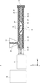
- FIG. 1 is a side view illustrating the configuration of the resin extruder according to the first embodiment.
- the resin extruder 1 is, for example, a continuous twin-screw extruder for resin.
- the resin extruder 1 includes a drive unit 10, a speed reducer 11, a cylinder 20, and screws 21 and 22.
- the resin extruder 1 is used in a mixing process and a volatilization process of the resin material 51.
- an XYZ orthogonal coordinate axis system is introduced.
- the direction in which the cylinder 20 extends is the X-axis direction
- the two directions orthogonal to the X-axis direction are the Y-axis direction and the Z-axis direction.
- the Z-axis direction is the vertical direction
- the XY plane is the horizontal plane.
- the + Z-axis direction is upward
- the direction in which the resin material 51 is extruded by the resin extruder 1 is the + X-axis direction.
- the vertical direction and the horizontal direction are used in the meaning of including an unavoidable error when installing the resin extruder 1 in the strict vertical direction and the horizontal direction.
- the drive unit 10 is arranged on one end side of the cylinder 20, for example, on the ⁇ X axis direction side of the cylinder 20.
- the drive unit 10 rotates the screws 21 and 22.
- the drive unit 10 is, for example, a motor.
- the speed reducer 11 is arranged between the drive unit 10 and the screws 21 and 22. The speed reducer 11 adjusts the rotation of the drive unit 10 and transmits it to the screws 21 and 22. Therefore, the screws 21 and 22 are rotated by the power source of the drive unit 10 adjusted by the speed reducer 11.
- the cylinder 20 is a tubular member extending in the X-axis direction.
- the cylinder 20 has a hollow portion inside.
- Two screws 21 and 22 are housed inside the cylinder 20.
- a hopper 13 for charging the resin material 51 is provided above the cylinder 20 on the ⁇ X axis direction side.
- a discharge port 14 for discharging the kneaded resin material is provided at the + X-axis direction end of the cylinder 20.
- the screws 21 and 22 are inserted through the opening on the ⁇ X axis direction side of the cylinder 20.
- the root portions of the screws 21 and 22 on the ⁇ X axis direction side protrude outward from the opening of the cylinder 20 and are connected to the drive portion 10 via the speed reducer 11.
- the screw 21 rotates about a rotation shaft 37 extending in the X-axis direction.
- the screw 22 rotates about a rotation shaft 38 extending in the X-axis direction at a position adjacent to the screw 21 in the Y-axis direction.
- the rotation shaft 37 and the rotation shaft 38 are arranged in parallel with a space in the Y-axis direction.
- the inner surface of the cylinder 20 includes the inner surface of the cylinder along the locus of rotation of the outer peripheral edges of the screws 21 and 22. Roughly speaking, the inner surface of the cylinder along the locus of rotation of the outer peripheral edge of the screw 21 and the inner surface of the cylinder along the locus of rotation of the outer peripheral edge of the screw 22 are combined.
- the cross section of the inner surface of the cylinder 20 orthogonal to the X axis has a figure eight shape in which a part of two circles is connected.
- the screw 21 is arranged between the upstream transport screw 31 for transporting the resin material, the downstream transport screw 35, and the upstream transport screw 31 and the downstream transport screw 35, and is a rotor type screw 33 for kneading the resin material.
- the screw 22 is arranged on the ⁇ Y axis direction side of the screw 21.
- the screw 22 is arranged between the upstream transport screw 32 and the downstream transport screw 36 for transporting the resin material, and between the upstream transport screw 32 and the downstream transport screw 36, and is a rotor type screw 34 for kneading the resin material. Consists of.
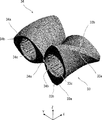
- FIG. 2 is an enlarged view of a portion of the rotor type screw shown in FIG. 1 surrounded by a broken line A.
- the rotor type screws 33 and 34 have a shape in which the flights 33a and 34a are spirally twisted with respect to the axis.
- the flights 33a and 34a have mountain peaks 33b and 34b.
- the rotor type screws 33 and 34 are formed with holes 33c and 34c to be fitted with the rotating shafts 37 and 38 (see FIG. 1).
- the outer diameters and shapes of the rotor type screws 33 and 34 are the same.
- FIG. 1 will be referred to as appropriate.
- the resin material 51 charged into the cylinder 20 from the hopper 13 in a powder state is transferred in the + X-axis direction by the upstream transport screws 31 and 32, and inside the cylinder 20 from a heater (not shown) attached to the cylinder 20. It melts by heat and kneading with rotor type screws 33 and 34.
- the kneaded resin is further conveyed in the + X-axis direction by the downstream transport screws 35 and 36 and discharged from the discharge port 14.
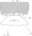
- FIG. 3 is a diagram showing a cross-sectional shape perpendicular to the axial direction of the rotor type screw according to Comparative Example 1.
- the cross section corresponds to a cross section along the VV line of the resin extruder 1 shown in FIG.
- the rotor type screw 533 rotates in the direction of arrow R51
- the rotor type screw 534 rotates in the direction of arrow R52.
- the outer diameters and shapes of the rotor type screws 533 and 534 are the same. Therefore, in the following, the shape will be described using the rotor type screw 533 as an example.
- FIG. 4 is an enlarged view of the area surrounded by the broken line B in FIG.
- the peak portion 533b and the cylinder of the flight 533a face the inner surface of the cylinder 20 from the front point to the rear point in the rotational direction. It is formed so that the gap between the 20 and the inner surface is constant.
- the gap between the mountaintop portion 533b and the inner surface of the cylinder 20 is simply referred to as a gap.
- the inventor of the present application uses the rotor type screw 533 and 534 according to Comparative Example 1 in the resin extruder 1 to excessively raise the temperature of the resin. It was found that it may be difficult to knead and disperse sufficiently.
- the resin material that is difficult to knead or disperse is, for example, a plurality of resins having different viscosities or a filler having a strong cohesive force.
- a resin extruder it is important to allow shear deformation and elongation deformation to act on the resin material in kneading or dispersing the resin material.
- the energy applied to the resin material is used not only for kneading or dispersing the resin material but also for rotating the resin material. Since heat is generated when the resin material is rotated, the temperature of the resin material rises when the resin material is sheared and deformed. On the other hand, when the resin material is stretched and deformed, the energy given to the resin material is mainly used for kneading or dispersing the resin material.
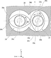
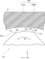
- FIG. 5 is a diagram showing a cross-sectional shape perpendicular to the axial direction of the rotor type screw according to the first embodiment.
- the cross section corresponds to a cross section along the VV line of the resin extruder 1 shown in FIG.
- the rotor type screw 33 rotates in the direction of arrow R1
- the rotor type screw 34 rotates in the direction of arrow R2.
- the outer diameters and shapes of the rotor type screws 33 and 34 are the same. Therefore, in the following, the shape will be described using the rotor type screw 33 as an example.
- FIG. 6 is an enlarged view of the area surrounded by the broken line C in FIG.
- the peak portion 33b and the cylinder of the flight 33a face the inner surface of the cylinder 20 from the front point to the rear point in the rotational direction. It is formed so that the gap between the 20 and the inner surface changes.
- the gap between the mountain top portion 33b and the inner surface of the cylinder 20 is simply referred to as a gap.
- the rotor type screw 33 has a cross section perpendicular to the axial direction, and the peak portion 33b of the flight 33a is formed so that the size of the gap gradually decreases from the front point P1 to the rear point P2. There is. That is, the size W2 of the gap at the point P2 behind the rotation direction R1 of the mountaintop 33b is smaller than the size W1 of the gap at the point P1 in front.
- FIG. 7 is a schematic view illustrating the action of elongation deformation exerted on the resin material by the rotor type screw according to the first embodiment.
- the resin material existing in the gap flows in the direction of arrow f1.
- the resin material existing in the gap is in a state of high stress and pressure.
- the matrix M1 which is the base material of the resin material at the entrance of the gap, extends in the direction of the arrow f1 when it is swept in the direction of the arrow f1 under the condition that the stress and pressure are high and the flow resistance is large in the tapered flow path. Then, at the exit of the gap, it is deformed like the matrix M2.
- the entrance of the gap is the position of the point P1 in front of the peak portion 33b of the flight 33a in the rotational direction
- the exit of the gap is the position of the point P2 behind the peak portion 33b of the flight 33a in the rotational direction.
- the base material of the resin material passing through the gap is stretched.
- the base material tends to collapse, so that kneading of a plurality of base materials, which are constituents of the resin material, is promoted.
- SEI specific energy of the extruder was determined for each of the resin extruder using the rotor screw according to the first embodiment and the resin extruder using the rotor screw according to the comparative example. [KWh / kg] was changed. SEI is obtained by dividing the power consumption [kW] of the extruder by the processing amount [kg / h] of the extruder, and is an index of the energy given to the resin material by the extruder. The SEI was changed by adjusting the opening degree of the throttle valve installed downstream of the kneading portion of the twin-screw extruder CMP69.
- FIG. 8 is a graph showing the results of a test comparing the kneading performance of the rotor type screw according to the first embodiment and the rotor type screw according to the comparative example.
- the horizontal axis is SEI [kWh / kg]
- the vertical axis is the number of gels [gel / m 2 ] per unit area in the film.
- the solid line shown in the figure is an approximate line obtained from the result of the resin extruder adopting the rotor type screw according to the first embodiment
- the broken line is the approximate line obtained from the result of the rotor type screw according to the comparative example. It is an approximate line obtained from the result of the resin extruder. From the approximate line shown in FIG.
- the number of gels in the film when the SEI is the same as compared with the case where the rotor type screw according to the comparative example is adopted. It can be inferred that is reduced by about 20 to 50%.
- the deformation energy applied to the resin material is almost the same. It is believed that there is. Therefore, when the rotor type screw according to the first embodiment is adopted, the number of gels in the film is significantly reduced as compared with the case where the rotor type screw according to the comparative example is adopted. It can be said that the elongation deformation can be effectively applied.
- the inventors of the present application have found the value of the ratio of the size of the gap between the front points in the rotation direction of the mountaintop 33b to the size of the gap between the rear points (the size of the gap between the front points / It was found that the size of the gap between the rear points) is preferably 2 or more or 1/2 or less. Further, through this test, the inventors of the present application have found that the smaller of the size of the gap between the front points and the size of the gap between the rear points in the rotation direction of the mountaintop 33b is 1/10 or less of the diameter of the cylinder. I found that it was preferable. Furthermore, the inventors of the present application have found through this test that it is preferable that the leads of the flights 33a and 34a are at least four times the diameter of the cylinder 20.
- FIG. 9 is a diagram illustrating a modification 1 of the shape of the rotor type screw according to the first embodiment. Note that FIG. 9 corresponds to the enlarged view of FIG. Further, since the rotor type screws 33 and 34 have the same shape, the modification 1 will be described by taking the rotor type screw 133 corresponding to the rotor type screw 33 as an example. As shown in FIG. 9, the rotor type screw 133 has a cross section perpendicular to the axial direction, and the peak portion 133b of the flight 133a is directed from the front point P11 to the rear point P12 toward the peak portion 133b and the inner surface of the cylinder 20. It is formed so that the size of the gap between the screw and the screw gradually increases.
- the gap between the summit portion 133b and the inner surface of the cylinder 20 is simply referred to as a gap. That is, the size W12 of the gap at the point P12 behind the rotation direction R11 of the mountaintop portion 133b is larger than the size W11 of the gap at the point P11 in front.
- FIG. 10 is a schematic view illustrating the action of elongation deformation exerted on the resin material by the rotor type screw according to the first modification.
- the resin material existing in the gap flows in the direction of arrow f11.
- the resin material existing in the gap is in a state of high stress and pressure.
- the matrix M11 at the entrance of the gap is swept in the direction of the arrow f11 under the condition that the stress and pressure are high and the flow resistance is large in the divergent flow path, the matrix M11 is elongated in a direction substantially perpendicular to the direction of the arrow f11. At the exit of the gap, it deforms like a matrix M12.
- the entrance of the gap is the position of the point P11 in front of the peak portion 133b of the flight 133a in the rotational direction
- the exit of the gap is the position of the point P12 behind the peak portion 133b of the flight 133a in the rotational direction.
- the base material of the resin material passing through the gap is stretched.
- the base material tends to collapse, so that kneading of a plurality of base materials, which are constituents of the resin material, is promoted.
- FIG. 11 is a diagram illustrating a modified example 2 of the shape of the rotor type screw according to the first embodiment. Note that FIG. 11 corresponds to the enlarged view of FIG. Further, since the rotor type screws 33 and 34 have the same shape, the modified example 2 will be described by taking the rotor type screw 233 corresponding to the rotor type screw 33 as an example.
- the front portion 233bA of the mountaintop portion 233b of the flight 233a is a point P22 rearward from the front point P21 as in the mountaintop portion 133b shown in FIG. It is formed so that the size of the gap gradually increases toward. That is, the size W22 of the gap at the point P22 behind the rotation direction R21 of the mountaintop portion 233b is larger than the size W21 of the gap at the point P21 in front.
- the rear portion 233bB of the mountaintop portion 233b of the flight 233a has a gap from the front point P22 toward the rear point P23 as in the mountaintop portion 33b shown in FIG. It is formed so that its size gradually decreases. That is, the size W23 of the gap at the point P23 behind the rotation direction R21 of the mountaintop portion 233b is smaller than the size W22 of the gap at the point P22 in front.
- the resin material passing through the gap can be subjected to elongation deformation. This promotes kneading of the resin material.
- FIG. 12 is a diagram illustrating a modified example 3 of the shape of the rotor type screw according to the first embodiment. Note that FIG. 12 corresponds to the enlarged view of FIG. Further, since the rotor type screws 33 and 34 have the same shape, the modified example 3 will be described by taking the rotor type screw 333 corresponding to the rotor type screw 33 as an example.
- the front portion 333bA of the mountaintop portion 333b of the flight 333a is a point P32 rearward from the front point P31 as in the mountaintop portion 33b shown in FIG. It is formed so that the size of the gap gradually decreases toward. That is, the size W32 of the gap at the point P32 behind the rotation direction R31 of the mountaintop portion 333b is smaller than the size W31 of the gap at the point P31 in front.
- the rear portion 333bB of the mountain top portion 333b of the flight 333a has a gap from the front point P32 toward the rear point P33 as in the mountain top portion 133b shown in FIG. It is formed so that its size gradually increases. That is, the size W33 of the gap at the point P33 behind the rotation direction R31 of the mountaintop portion 333b is larger than the size W32 of the gap at the point P32 in front.
- the resin material passing through the gap can be subjected to elongation deformation. This promotes kneading of the resin material.
Landscapes
- Engineering & Computer Science (AREA)
- Mechanical Engineering (AREA)
- Processing And Handling Of Plastics And Other Materials For Molding In General (AREA)
- Extrusion Moulding Of Plastics Or The Like (AREA)
Abstract
Provided is a resin extruder which can efficiently improve the performance of kneading a resin material. A resin extruder (1) according to one embodiment comprises: a cylinder (20); and a rotor-type screw (33) that is disposed inside the cylinder (20) and kneads a resin material (51). In the rotor-type screw (33), a peak section (33b) of a flight (33a) is formed such that, in a cross section perpendicular to the axial direction, a gap between the peak section (33b) and the inner surface of the cylinder (20) changes going from a point in the front in the rotation direction to a point in the rear in the rotation direction.
Description
本発明は、樹脂用押出機、ロータ型スクリュ及び樹脂製造方法に関する。
The present invention relates to a resin extruder, a rotor screw, and a resin manufacturing method.
樹脂材料の混合プロセスや脱揮プロセスに用いられる押出機が知られている。押出機は、例えば特許文献1に記載されているように、シャフトに嵌められたスクリュを有し、スクリュはシャフトの軸方向において、機能別に分割されている。具体的には、樹脂材料の投入部には主に樹脂材料を搬送するためのスクリュが設けられ、その下流側には樹脂材料の可塑化や混練を行うためのスクリュが設けられている。さらにその下流側には混練された樹脂材料をダイ(吐出口)に向けて搬送するスクリュが設けられている。樹脂材料の可塑化や混練を行うためのスクリュとして、ニーディングディスク型スクリュ、あるいは、ロータ型スクリュが知られている。
Extruders used in resin material mixing processes and volatilization processes are known. The extruder has a screw fitted to a shaft, for example, as described in Patent Document 1, and the screw is divided according to a function in the axial direction of the shaft. Specifically, a screw for transporting the resin material is mainly provided in the input portion of the resin material, and a screw for plasticizing and kneading the resin material is provided on the downstream side thereof. Further, on the downstream side thereof, a screw for transporting the kneaded resin material toward the die (discharge port) is provided. As a screw for plasticizing and kneading a resin material, a kneading disc type screw or a rotor type screw is known.
樹脂材料を混練するロータ型スクリュを備えた樹脂用押出機の混練性能を向上させる必要がある。
It is necessary to improve the kneading performance of the resin extruder equipped with a rotor type screw that kneads the resin material.
その他の課題と新規な特徴は、本明細書の記述及び添付図面から明らかになるであろう。
Other issues and new features will become apparent from the description and accompanying drawings of this specification.
一実施の形態に係る樹脂用押出機は、シリンダと、前記シリンダ内に配置され、樹脂材料を混練するロータ型スクリュと、を備え、前記ロータ型スクリュは、軸線方向に垂直な断面で、フライトの山頂部が、回転方向の前方の点から後方の点に向かって前記山頂部と前記シリンダの内面との間隙が変化するように形成されている。
The resin extruder according to the embodiment includes a cylinder and a rotor screw that is arranged in the cylinder and kneads the resin material, and the rotor screw has a cross section perpendicular to the axial direction and a flight. The top of the mountain is formed so that the gap between the top of the mountain and the inner surface of the cylinder changes from a front point in the rotation direction to a rear point.
前記一実施の形態によれば、樹脂材料の混練性能を効率的に向上させることができる樹脂用押出機を提供することができる。
According to the above-described embodiment, it is possible to provide a resin extruder capable of efficiently improving the kneading performance of the resin material.
以下、具体的な実施の形態について、図面を参照しながら詳細に説明する。ただし、以下の実施の形態に限定される訳ではない。説明を明確にするため、以下の記載及び図面は、適宜簡略化されている。各図面において、同一の要素には同一の符号が付されており、必要に応じて重複説明は省略されている。また、図面が煩雑にならないように、ハッチングが省略されている部分がある。
Hereinafter, specific embodiments will be described in detail with reference to the drawings. However, the present invention is not limited to the following embodiments. The following description and drawings have been simplified as appropriate to clarify the description. In each drawing, the same elements are designated by the same reference numerals, and duplicate explanations are omitted as necessary. In addition, there is a part where hatching is omitted so that the drawing is not complicated.
(実施の形態1)
<樹脂用押出機の全体構成>
まず、図1を参照して、実施の形態1に係る樹脂用押出機の全体構成について説明する。 (Embodiment 1)
<Overall configuration of resin extruder>
First, with reference to FIG. 1, the overall configuration of the resin extruder according to the first embodiment will be described.
<樹脂用押出機の全体構成>
まず、図1を参照して、実施の形態1に係る樹脂用押出機の全体構成について説明する。 (Embodiment 1)
<Overall configuration of resin extruder>
First, with reference to FIG. 1, the overall configuration of the resin extruder according to the first embodiment will be described.
図1は、実施の形態1に係る樹脂用押出機の構成を例示した側面図である。図1に示すように、樹脂用押出機1は、例えば樹脂用の連続式二軸スクリュ押出機である。樹脂用押出機1は、駆動部10、減速機11、シリンダ20、スクリュ21及び22を備えている。樹脂用押出機1は、樹脂材料51の混合プロセスや脱揮プロセスなどに用いられる。
FIG. 1 is a side view illustrating the configuration of the resin extruder according to the first embodiment. As shown in FIG. 1, the resin extruder 1 is, for example, a continuous twin-screw extruder for resin. The resin extruder 1 includes a drive unit 10, a speed reducer 11, a cylinder 20, and screws 21 and 22. The resin extruder 1 is used in a mixing process and a volatilization process of the resin material 51.
ここで、樹脂用押出機1の説明の便宜のために、XYZ直交座標軸系を導入する。例えば、シリンダ20が延びる方向をX軸方向とし、X軸方向に直交する2方向を、Y軸方向及びZ軸方向とする。例えば、Z軸方向は、鉛直方向であり、XY平面は、水平面である。また、+Z軸方向は、上方であり、樹脂用押出機1で樹脂材料51が押し出される方向を+X軸方向とする。ここで、鉛直方向及び水平方向は、厳密な鉛直方向及び水平方向に、樹脂用押出機1を設置する際の不可避な誤差を含む意味で用いている。
Here, for convenience of explanation of the resin extruder 1, an XYZ orthogonal coordinate axis system is introduced. For example, the direction in which the cylinder 20 extends is the X-axis direction, and the two directions orthogonal to the X-axis direction are the Y-axis direction and the Z-axis direction. For example, the Z-axis direction is the vertical direction, and the XY plane is the horizontal plane. The + Z-axis direction is upward, and the direction in which the resin material 51 is extruded by the resin extruder 1 is the + X-axis direction. Here, the vertical direction and the horizontal direction are used in the meaning of including an unavoidable error when installing the resin extruder 1 in the strict vertical direction and the horizontal direction.
駆動部10は、シリンダ20の一端側、例えば、シリンダ20の-X軸方向側に配置されている。駆動部10は、スクリュ21及び22を回転させる。駆動部10は、例えば、モータである。減速機11は、駆動部10とスクリュ21及び22との間に配置されている。減速機11は、駆動部10の回転を調整してスクリュ21及び22に伝達させる。よって、スクリュ21及び22は、減速機11で調整された駆動部10の動力源によって回転する。
The drive unit 10 is arranged on one end side of the cylinder 20, for example, on the −X axis direction side of the cylinder 20. The drive unit 10 rotates the screws 21 and 22. The drive unit 10 is, for example, a motor. The speed reducer 11 is arranged between the drive unit 10 and the screws 21 and 22. The speed reducer 11 adjusts the rotation of the drive unit 10 and transmits it to the screws 21 and 22. Therefore, the screws 21 and 22 are rotated by the power source of the drive unit 10 adjusted by the speed reducer 11.
シリンダ20は、X軸方向に延びた筒状の部材である。シリンダ20は、内部に中空部を有している。シリンダ20の内部には、2つのスクリュ21及び22が収容されている。シリンダ20の-X軸方向側の上方には、樹脂材料51を投入するためのホッパ13が設けられている。シリンダ20の+X軸方向側端部には混練された樹脂材が排出される排出口14が設けられている。
The cylinder 20 is a tubular member extending in the X-axis direction. The cylinder 20 has a hollow portion inside. Two screws 21 and 22 are housed inside the cylinder 20. A hopper 13 for charging the resin material 51 is provided above the cylinder 20 on the −X axis direction side. A discharge port 14 for discharging the kneaded resin material is provided at the + X-axis direction end of the cylinder 20.
スクリュ21及び22は、シリンダ20の-X軸方向側の開口部から挿入されている。スクリュ21及び22の-X軸方向側の根元部は、シリンダ20の開口部から外側に出ており、減速機11を介して駆動部10に接続されている。スクリュ21は、X軸方向に延びた回転軸37を中心に回転する。スクリュ22は、スクリュ21に対してY軸方向に隣接した位置でX軸方向に延びた回転軸38を中心に回転する。回転軸37と回転軸38は、Y軸方向に間隔を空けて平行に配置されている。
The screws 21 and 22 are inserted through the opening on the −X axis direction side of the cylinder 20. The root portions of the screws 21 and 22 on the −X axis direction side protrude outward from the opening of the cylinder 20 and are connected to the drive portion 10 via the speed reducer 11. The screw 21 rotates about a rotation shaft 37 extending in the X-axis direction. The screw 22 rotates about a rotation shaft 38 extending in the X-axis direction at a position adjacent to the screw 21 in the Y-axis direction. The rotation shaft 37 and the rotation shaft 38 are arranged in parallel with a space in the Y-axis direction.
シリンダ20の内面は、スクリュ21及び22の外周縁が回転する軌跡に沿った円筒内面を含んでいる。おおまかに言えば、スクリュ21の外周縁が回転する軌跡に沿った円筒内面と、スクリュ22の外周縁が回転する軌跡に沿った円筒内面と、が結合したものとなっている。例えば、シリンダ20の内面のX軸に直交する断面(軸線方向に垂直な断面)は、2つの円の一部が結合した8の字状となっている。
The inner surface of the cylinder 20 includes the inner surface of the cylinder along the locus of rotation of the outer peripheral edges of the screws 21 and 22. Roughly speaking, the inner surface of the cylinder along the locus of rotation of the outer peripheral edge of the screw 21 and the inner surface of the cylinder along the locus of rotation of the outer peripheral edge of the screw 22 are combined. For example, the cross section of the inner surface of the cylinder 20 orthogonal to the X axis (cross section perpendicular to the axial direction) has a figure eight shape in which a part of two circles is connected.
スクリュ21は、樹脂材料を搬送するための上流側搬送スクリュ31、下流側搬送スクリュ35、上流側搬送スクリュ31と下流側搬送スクリュ35の間に配置され樹脂材料を混練するためのロータ型スクリュ33から構成される。スクリュ22は、スクリュ21の-Y軸方向側に配置されている。スクリュ22は、樹脂材料を搬送するための上流側搬送スクリュ32及び下流側搬送スクリュ36、上流側搬送スクリュ32と下流側搬送スクリュ36の間に配置され樹脂材料を混練するためのロータ型スクリュ34から構成される。
The screw 21 is arranged between the upstream transport screw 31 for transporting the resin material, the downstream transport screw 35, and the upstream transport screw 31 and the downstream transport screw 35, and is a rotor type screw 33 for kneading the resin material. Consists of. The screw 22 is arranged on the −Y axis direction side of the screw 21. The screw 22 is arranged between the upstream transport screw 32 and the downstream transport screw 36 for transporting the resin material, and between the upstream transport screw 32 and the downstream transport screw 36, and is a rotor type screw 34 for kneading the resin material. Consists of.
<ロータ型スクリュの構成>
次に、ロータ型スクリュ33及び34の構成について説明する。
図2は、図1に示すロータ型スクリュの破線Aで囲んだ部分の拡大図である。図2に示すように、ロータ型スクリュ33及び34は、フライト33a及び34aが軸線に対し螺旋状にねじれた形状を有する。フライト33a及び34aは、山頂部33b及び34bを有している。また、ロータ型スクリュ33及び34には、回転軸37及び38(図1参照)と嵌め合う穴33c及び34cが形成されている。ロータ型スクリュ33及び34の外径や形状は同じである。 <Structure of rotor type screw>
Next, the configurations of the rotor type screws 33 and 34 will be described.
FIG. 2 is an enlarged view of a portion of the rotor type screw shown in FIG. 1 surrounded by a broken line A. As shown in FIG. 2, the rotor type screws 33 and 34 have a shape in which the flights 33a and 34a are spirally twisted with respect to the axis. The flights 33a and 34a have mountain peaks 33b and 34b. Further, the rotor type screws 33 and 34 are formed with holes 33c and 34c to be fitted with the rotating shafts 37 and 38 (see FIG. 1). The outer diameters and shapes of the rotor type screws 33 and 34 are the same.
次に、ロータ型スクリュ33及び34の構成について説明する。
図2は、図1に示すロータ型スクリュの破線Aで囲んだ部分の拡大図である。図2に示すように、ロータ型スクリュ33及び34は、フライト33a及び34aが軸線に対し螺旋状にねじれた形状を有する。フライト33a及び34aは、山頂部33b及び34bを有している。また、ロータ型スクリュ33及び34には、回転軸37及び38(図1参照)と嵌め合う穴33c及び34cが形成されている。ロータ型スクリュ33及び34の外径や形状は同じである。 <Structure of rotor type screw>
Next, the configurations of the rotor type screws 33 and 34 will be described.
FIG. 2 is an enlarged view of a portion of the rotor type screw shown in FIG. 1 surrounded by a broken line A. As shown in FIG. 2, the rotor type screws 33 and 34 have a shape in which the
<樹脂用押出機の動作>
次に、実施の形態1に係る樹脂用押出機1の動作について説明する。なお、以下の説明では、図1について適宜参照する。
ホッパ13からシリンダ20に粉末の状態で投入された樹脂材料51は、上流側搬送スクリュ31及び32によって+X軸方向に移送され、シリンダ20の内部において、シリンダ20に取付けられた図示しないヒータからの熱およびロータ型スクリュ33及び34によって混練されることにより溶融する。混練された樹脂は、下流側搬送スクリュ35及び36によってさらに+X軸方向に搬送されて排出口14から排出される。 <Operation of resin extruder>
Next, the operation of theresin extruder 1 according to the first embodiment will be described. In the following description, FIG. 1 will be referred to as appropriate.
Theresin material 51 charged into the cylinder 20 from the hopper 13 in a powder state is transferred in the + X-axis direction by the upstream transport screws 31 and 32, and inside the cylinder 20 from a heater (not shown) attached to the cylinder 20. It melts by heat and kneading with rotor type screws 33 and 34. The kneaded resin is further conveyed in the + X-axis direction by the downstream transport screws 35 and 36 and discharged from the discharge port 14.
次に、実施の形態1に係る樹脂用押出機1の動作について説明する。なお、以下の説明では、図1について適宜参照する。
ホッパ13からシリンダ20に粉末の状態で投入された樹脂材料51は、上流側搬送スクリュ31及び32によって+X軸方向に移送され、シリンダ20の内部において、シリンダ20に取付けられた図示しないヒータからの熱およびロータ型スクリュ33及び34によって混練されることにより溶融する。混練された樹脂は、下流側搬送スクリュ35及び36によってさらに+X軸方向に搬送されて排出口14から排出される。 <Operation of resin extruder>
Next, the operation of the
The
<比較例1に係るロータ型スクリュの形状>
次に、発明者が事前に検討した比較例1に係るロータ型スクリュについて説明する。
図3は、比較例1に係るロータ型スクリュの軸線方向に垂直な断面の形状を示す図である。当該断面は、図1に示す樹脂用押出機1のV-V線に沿う断面に相当する。図3に示すように、ロータ型スクリュ533は矢印R51の方向に回転し、ロータ型スクリュ534は矢印R52の方向に回転する。ロータ型スクリュ533及び534の外径や形状は同じである。よって、以下ではロータ型スクリュ533を例に形状を説明する。 <Shape of rotor type screw according to Comparative Example 1>
Next, the rotor type screw according to Comparative Example 1 examined in advance by the inventor will be described.
FIG. 3 is a diagram showing a cross-sectional shape perpendicular to the axial direction of the rotor type screw according to Comparative Example 1. The cross section corresponds to a cross section along the VV line of theresin extruder 1 shown in FIG. As shown in FIG. 3, the rotor type screw 533 rotates in the direction of arrow R51, and the rotor type screw 534 rotates in the direction of arrow R52. The outer diameters and shapes of the rotor type screws 533 and 534 are the same. Therefore, in the following, the shape will be described using the rotor type screw 533 as an example.
次に、発明者が事前に検討した比較例1に係るロータ型スクリュについて説明する。
図3は、比較例1に係るロータ型スクリュの軸線方向に垂直な断面の形状を示す図である。当該断面は、図1に示す樹脂用押出機1のV-V線に沿う断面に相当する。図3に示すように、ロータ型スクリュ533は矢印R51の方向に回転し、ロータ型スクリュ534は矢印R52の方向に回転する。ロータ型スクリュ533及び534の外径や形状は同じである。よって、以下ではロータ型スクリュ533を例に形状を説明する。 <Shape of rotor type screw according to Comparative Example 1>
Next, the rotor type screw according to Comparative Example 1 examined in advance by the inventor will be described.
FIG. 3 is a diagram showing a cross-sectional shape perpendicular to the axial direction of the rotor type screw according to Comparative Example 1. The cross section corresponds to a cross section along the VV line of the
図4は、図3の破線Bで囲った領域の拡大図である。図4に示すように、ロータ型スクリュ533は、フライト533aの山頂部533bが、シリンダ20の内面と対向する状態で、回転方向の前方の点から後方の点に向かって、山頂部533bとシリンダ20の内面との間隙が一定になるように形成されている。以下、山頂部533bとシリンダ20の内面との間隙を、単に間隙と呼ぶ。フライト533aの山頂部533bの回転方向R51の前方の点P51の間隙の大きさ(間隙の幅)W51と、中間の点P52の間隙の大きさW52と、後方の点P53の間隙の大きさW53は同じである。
FIG. 4 is an enlarged view of the area surrounded by the broken line B in FIG. As shown in FIG. 4, in the rotor type screw 533, the peak portion 533b and the cylinder of the flight 533a face the inner surface of the cylinder 20 from the front point to the rear point in the rotational direction. It is formed so that the gap between the 20 and the inner surface is constant. Hereinafter, the gap between the mountaintop portion 533b and the inner surface of the cylinder 20 is simply referred to as a gap. The size of the gap (gap width) W51 at the front point P51 in the rotation direction R51 of the mountaintop portion 533b of the flight 533a, the size W52 of the gap between the intermediate points P52, and the size of the gap W53 at the rear point P53. Is the same.
本願の発明者は、混練または分散させるのが難い樹脂材料である場合、樹脂用押出機1に、比較例1に係るロータ型スクリュ533及び534を用いると、樹脂の温度を過剰に上昇させることなく十分に混練・分散させるのが困難な場合があることを見いだした。ここで、混練または分散させるのが難い樹脂材料とは、例えば、粘度差のある複数の樹脂あるいは凝集力の強いフィラーなどである。
In the case of a resin material that is difficult to knead or disperse, the inventor of the present application uses the rotor type screw 533 and 534 according to Comparative Example 1 in the resin extruder 1 to excessively raise the temperature of the resin. It was found that it may be difficult to knead and disperse sufficiently. Here, the resin material that is difficult to knead or disperse is, for example, a plurality of resins having different viscosities or a filler having a strong cohesive force.
樹脂用押出機では、樹脂材料の混練または分散において、剪断変形および伸長変形を樹脂材料に作用させることが重要である。樹脂材料を剪断変形させた場合、樹脂材料に付与されたエネルギーが、樹脂材料の混練または分散に使われるだけでなく、樹脂材料の回転にも使われる。樹脂材料を回転させる際に熱が生じるので、樹脂材料を剪断変形させた場合には樹脂材料の温度が上昇する。これに対し、樹脂材料を伸長変形させた場合には、樹脂材料に付与されたエネルギーが、主として樹脂材料の混練または分散に使われる。つまり、樹脂材料を、伸長変形させた場合の方が、剪断変形させた場合よりも発熱が抑制され、より効率的に混練または分散させることができる。上述した、樹脂用押出機1に比較例1に係るロータ型スクリュ533及び534を用いた場合では、樹脂材料に対して伸長変形を十分に作用させることができないと推測される。
In a resin extruder, it is important to allow shear deformation and elongation deformation to act on the resin material in kneading or dispersing the resin material. When the resin material is sheared and deformed, the energy applied to the resin material is used not only for kneading or dispersing the resin material but also for rotating the resin material. Since heat is generated when the resin material is rotated, the temperature of the resin material rises when the resin material is sheared and deformed. On the other hand, when the resin material is stretched and deformed, the energy given to the resin material is mainly used for kneading or dispersing the resin material. That is, when the resin material is elongated and deformed, heat generation is suppressed as compared with the case where the resin material is sheared and deformed, and the resin material can be kneaded or dispersed more efficiently. When the rotor type screws 533 and 534 according to Comparative Example 1 are used in the resin extruder 1 described above, it is presumed that elongation deformation cannot be sufficiently applied to the resin material.
<実施の形態1に係るロータ型スクリュの形状>
次に、実施の形態1に係るロータ型スクリュについて説明する。
図5は、実施の形態1に係るロータ型スクリュの軸線方向に垂直な断面の形状を示す図である。当該断面は、図1に示す樹脂用押出機1のV-V線に沿う断面に相当する。図5に示すように、ロータ型スクリュ33は矢印R1の方向に回転し、ロータ型スクリュ34は矢印R2の方向に回転する。ロータ型スクリュ33及び34の外径や形状は同じである。よって、以下ではロータ型スクリュ33を例に形状を説明する。 <Shape of rotor type screw according to the first embodiment>
Next, the rotor type screw according to the first embodiment will be described.
FIG. 5 is a diagram showing a cross-sectional shape perpendicular to the axial direction of the rotor type screw according to the first embodiment. The cross section corresponds to a cross section along the VV line of theresin extruder 1 shown in FIG. As shown in FIG. 5, the rotor type screw 33 rotates in the direction of arrow R1, and the rotor type screw 34 rotates in the direction of arrow R2. The outer diameters and shapes of the rotor type screws 33 and 34 are the same. Therefore, in the following, the shape will be described using the rotor type screw 33 as an example.
次に、実施の形態1に係るロータ型スクリュについて説明する。
図5は、実施の形態1に係るロータ型スクリュの軸線方向に垂直な断面の形状を示す図である。当該断面は、図1に示す樹脂用押出機1のV-V線に沿う断面に相当する。図5に示すように、ロータ型スクリュ33は矢印R1の方向に回転し、ロータ型スクリュ34は矢印R2の方向に回転する。ロータ型スクリュ33及び34の外径や形状は同じである。よって、以下ではロータ型スクリュ33を例に形状を説明する。 <Shape of rotor type screw according to the first embodiment>
Next, the rotor type screw according to the first embodiment will be described.
FIG. 5 is a diagram showing a cross-sectional shape perpendicular to the axial direction of the rotor type screw according to the first embodiment. The cross section corresponds to a cross section along the VV line of the
図6は、図5の破線Cで囲った領域の拡大図である。図6に示すように、ロータ型スクリュ33は、フライト33aの山頂部33bが、シリンダ20の内面と対向する状態で、回転方向の前方の点から後方の点に向かって、山頂部33bとシリンダ20の内面との間隙が変化するように形成されている。以下、山頂部33bとシリンダ20の内面との間隙を、単に間隙と呼ぶ。ここでは、ロータ型スクリュ33は、軸線方向に垂直な断面で、フライト33aの山頂部33bが、前方の点P1から後方の点P2に向かって間隙の大きさが漸次減少するように形成されている。すなわち、山頂部33bの回転方向R1の後方の点P2の間隙の大きさW2の方が前方の点P1の間隙の大きさW1よりも小さくなっている。
FIG. 6 is an enlarged view of the area surrounded by the broken line C in FIG. As shown in FIG. 6, in the rotor type screw 33, the peak portion 33b and the cylinder of the flight 33a face the inner surface of the cylinder 20 from the front point to the rear point in the rotational direction. It is formed so that the gap between the 20 and the inner surface changes. Hereinafter, the gap between the mountain top portion 33b and the inner surface of the cylinder 20 is simply referred to as a gap. Here, the rotor type screw 33 has a cross section perpendicular to the axial direction, and the peak portion 33b of the flight 33a is formed so that the size of the gap gradually decreases from the front point P1 to the rear point P2. There is. That is, the size W2 of the gap at the point P2 behind the rotation direction R1 of the mountaintop 33b is smaller than the size W1 of the gap at the point P1 in front.
図7は、実施の形態1に係るロータ型スクリュにより樹脂材料に及ぼされる伸長変形の作用について説明する模式図である。図7に示すように、ロータ型スクリュ33が矢印R1の方向に回転すると、間隙に存在する樹脂材料は矢印f1の方向に流れる。間隙に存在する樹脂材料は応力及び圧力が高い状態になっている。間隙の入口にある樹脂材料の母材であるマトリックスM1は、先細りの流路において、応力及び圧力が高く流れ抵抗が大きい状況下で矢印f1の方向に押し流されると、矢印f1の方向に細長く伸長されて、間隙の出口ではマトリックスM2のように変形する。ここで、間隙の入口はフライト33aの山頂部33bの回転方向の前方の点P1の位置、間隙の出口はフライト33aの山頂部33bの回転方向の後方の点P2の位置である。
FIG. 7 is a schematic view illustrating the action of elongation deformation exerted on the resin material by the rotor type screw according to the first embodiment. As shown in FIG. 7, when the rotor type screw 33 rotates in the direction of arrow R1, the resin material existing in the gap flows in the direction of arrow f1. The resin material existing in the gap is in a state of high stress and pressure. The matrix M1, which is the base material of the resin material at the entrance of the gap, extends in the direction of the arrow f1 when it is swept in the direction of the arrow f1 under the condition that the stress and pressure are high and the flow resistance is large in the tapered flow path. Then, at the exit of the gap, it is deformed like the matrix M2. Here, the entrance of the gap is the position of the point P1 in front of the peak portion 33b of the flight 33a in the rotational direction, and the exit of the gap is the position of the point P2 behind the peak portion 33b of the flight 33a in the rotational direction.
このように、山頂部33bの回転方向の前方の点P1から後方の点P2に向かって間隙の大きさが漸次減少すると、間隙を通過する樹脂材料の母材が伸長される。樹脂材料の母材が伸長されると、母材は崩れやすくなるので、樹脂材料の構成成分である複数の母材の混練が促進される。
As described above, when the size of the gap gradually decreases from the front point P1 in the rotation direction of the mountaintop 33b toward the rear point P2, the base material of the resin material passing through the gap is stretched. When the base material of the resin material is stretched, the base material tends to collapse, so that kneading of a plurality of base materials, which are constituents of the resin material, is promoted.
<混練性能の比較試験>
次に、実施の形態1に係るロータ型スクリュと比較例に係るロータ型スクリュの混練性能を比較した試験について説明する。
本試験では、樹脂用押出機として、日本製鋼所製の二軸スクリュ押出機CMP69を用いた。二軸スクリュ押出機CMP69のシリンダの内径は69mmであり、スクリュ回転速度は240rpm、シリンダ設定温度は200℃、原料処理量は300kg/hに設定した。また、樹脂材料としてブロックコポリマーポリプロピレン(230℃、2.16kg荷重でのMFR(Melt Flow Rate):3)を使用した。 <Comparison test of kneading performance>
Next, a test comparing the kneading performance of the rotor type screw according to the first embodiment and the rotor type screw according to the comparative example will be described.
In this test, a twin-screw extruder CMP69 manufactured by Japan Steel Works was used as the resin extruder. The inner diameter of the cylinder of the twin-screw extruder CMP69 was 69 mm, the screw rotation speed was set to 240 rpm, the cylinder set temperature was set to 200 ° C., and the raw material processing amount was set to 300 kg / h. Further, as a resin material, block copolymer polypropylene (MFR (Melt Flow Rate): 3) at 230 ° C. and a load of 2.16 kg was used.
本試験では、実施の形態1に係るロータ型スクリュを採用した樹脂用押出機で混練した押出吐出物と、比較例に係るロータ型スクリュを採用した樹脂用押出機で混練した押出吐出物で、それぞれフィルムを作製した。そして、作製したそれぞれのフィルムについて、単位面積あたりに含まれるゲル数を数えた。フィルム中のゲルは、混練物中の粘度の高い成分あるいは分子量の高い成分の母材(マトリックス)の混練または分散が不十分な程、発生する。つまり、フィルム中の単位面積あたりのゲル数が少ないほど、混練性能が高いと判断することができる。
In this test, the extruded product kneaded by the resin extruder using the rotor screw according to the first embodiment and the extruded product kneaded by the resin extruder using the rotor screw according to the comparative example. Films were prepared for each. Then, the number of gels contained in each unit area of each produced film was counted. The gel in the film is generated so that the base material (matrix) having a high viscosity component or a high molecular weight component in the kneaded product is not sufficiently kneaded or dispersed. That is, it can be determined that the smaller the number of gels per unit area in the film, the higher the kneading performance.
また、本試験では、実施の形態1に係るロータ型スクリュを採用した樹脂用押出機と、比較例に係るロータ型スクリュを採用した樹脂用押出機のそれぞれについて、押出機の比エネルギー(SEI)[kWh/kg]を変更した。SEIは、押出機の消費動力[kW]を押出機の処理量[kg/h]で除したもので、押出機が樹脂材料に付与したエネルギーの指標である。SEIの変更は、二軸スクリュ押出機CMP69の混練部下流に設置されている絞りバルブの開度を調節することにより行った。
Further, in this test, the specific energy (SEI) of the extruder was determined for each of the resin extruder using the rotor screw according to the first embodiment and the resin extruder using the rotor screw according to the comparative example. [KWh / kg] was changed. SEI is obtained by dividing the power consumption [kW] of the extruder by the processing amount [kg / h] of the extruder, and is an index of the energy given to the resin material by the extruder. The SEI was changed by adjusting the opening degree of the throttle valve installed downstream of the kneading portion of the twin-screw extruder CMP69.
図8は、実施の形態1に係るロータ型スクリュと比較例に係るロータ型スクリュの混練性能を比較した試験の結果を示すグラフである。図中で、横軸はSEI[kWh/kg]であり、縦軸はフィルム中の単位面積あたりのゲル数[gel/m2]である。図中に示されている、実線は、実施の形態1に係るロータ型スクリュを採用した樹脂用押出機の結果より得られた近似線であり、破線は、比較例に係るロータ型スクリュを採用した樹脂用押出機の結果より得られた近似線である。図8に示す近似線より、実施の形態1に係るロータ型スクリュを採用した場合、比較例に係るロータ型スクリュを採用した場合と比べて、SEIを同じにしたときに、フィルム中のゲル数が20~50パーセントほど低減していると推察することができる。
FIG. 8 is a graph showing the results of a test comparing the kneading performance of the rotor type screw according to the first embodiment and the rotor type screw according to the comparative example. In the figure, the horizontal axis is SEI [kWh / kg], and the vertical axis is the number of gels [gel / m 2 ] per unit area in the film. The solid line shown in the figure is an approximate line obtained from the result of the resin extruder adopting the rotor type screw according to the first embodiment, and the broken line is the approximate line obtained from the result of the rotor type screw according to the comparative example. It is an approximate line obtained from the result of the resin extruder. From the approximate line shown in FIG. 8, when the rotor type screw according to the first embodiment is adopted, the number of gels in the film when the SEI is the same as compared with the case where the rotor type screw according to the comparative example is adopted. It can be inferred that is reduced by about 20 to 50%.
実施の形態1に係るロータ型スクリュを採用した場合と、比較例に係るロータ型スクリュを採用した場合で、SEIの値が同じであれば、樹脂材料に対して作用させる変形エネルギーはほぼ同じであると考えられる。よって、実施の形態1に係るロータ型スクリュを採用した場合では、比較例に係るロータ型スクリュを採用した場合よりも、フィルム中のゲル数が大幅に低減していることから、樹脂材料に対して伸長変形を効果的に作用させることができているといえる。
If the SEI value is the same between the case where the rotor type screw according to the first embodiment and the case where the rotor type screw according to the comparative example is adopted, the deformation energy applied to the resin material is almost the same. It is believed that there is. Therefore, when the rotor type screw according to the first embodiment is adopted, the number of gels in the film is significantly reduced as compared with the case where the rotor type screw according to the comparative example is adopted. It can be said that the elongation deformation can be effectively applied.
なお、本願の発明者らは、本試験を通じて、山頂部33bの回転方向の前方の点の間隙の大きさと後方の点の間隙の大きさとの比の値(前方の点の間隙の大きさ/後方の点の間隙の大きさ)が2以上または1/2以下であるのが好ましいことを見いだした。また、本願の発明者らは、本試験を通じて、山頂部33bの回転方向の前方の点の間隙の大きさと後方の点の間隙の大きさのいずれか小さい方がシリンダの径の1/10以下であるのが好ましいことを見いだした。さらに、本願の発明者らは、本試験を通じて、フライト33a及び34aのリードがシリンダ20の直径の4倍以上であるのが好ましいことを見いだした。
Throughout this test, the inventors of the present application have found the value of the ratio of the size of the gap between the front points in the rotation direction of the mountaintop 33b to the size of the gap between the rear points (the size of the gap between the front points / It was found that the size of the gap between the rear points) is preferably 2 or more or 1/2 or less. Further, through this test, the inventors of the present application have found that the smaller of the size of the gap between the front points and the size of the gap between the rear points in the rotation direction of the mountaintop 33b is 1/10 or less of the diameter of the cylinder. I found that it was preferable. Furthermore, the inventors of the present application have found through this test that it is preferable that the leads of the flights 33a and 34a are at least four times the diameter of the cylinder 20.
<実施の形態1に係るロータ型スクリュの形状の変形例1>
次に、実施の形態1に係るロータ型スクリュ33、34(図5及び図6参照)の変形例1について説明する。 <Modification example 1 of the shape of the rotor type screw according to the first embodiment>
Next, amodification 1 of the rotor type screws 33 and 34 (see FIGS. 5 and 6) according to the first embodiment will be described.
次に、実施の形態1に係るロータ型スクリュ33、34(図5及び図6参照)の変形例1について説明する。 <Modification example 1 of the shape of the rotor type screw according to the first embodiment>
Next, a
図9は、実施の形態1に係るロータ型スクリュの形状の変形例1について説明する図である。なお、図9は、図6の拡大図に対応する。また、ロータ型スクリュ33、34は同じ形状なので、変形例1は、ロータ型スクリュ33に対応するロータ型スクリュ133を例に説明する。図9に示すように、ロータ型スクリュ133は、軸線方向に垂直な断面で、フライト133aの山頂部133bが、前方の点P11から後方の点P12に向かって、山頂部133bとシリンダ20の内面との間隙の大きさが漸次増加するように形成されている。以下、山頂部133bとシリンダ20の内面との間隙を、単に間隙と呼ぶ。すなわち、山頂部133bの回転方向R11の後方の点P12の間隙の大きさW12の方が前方の点P11の間隙の大きさW11よりも大きくなっている。
FIG. 9 is a diagram illustrating a modification 1 of the shape of the rotor type screw according to the first embodiment. Note that FIG. 9 corresponds to the enlarged view of FIG. Further, since the rotor type screws 33 and 34 have the same shape, the modification 1 will be described by taking the rotor type screw 133 corresponding to the rotor type screw 33 as an example. As shown in FIG. 9, the rotor type screw 133 has a cross section perpendicular to the axial direction, and the peak portion 133b of the flight 133a is directed from the front point P11 to the rear point P12 toward the peak portion 133b and the inner surface of the cylinder 20. It is formed so that the size of the gap between the screw and the screw gradually increases. Hereinafter, the gap between the summit portion 133b and the inner surface of the cylinder 20 is simply referred to as a gap. That is, the size W12 of the gap at the point P12 behind the rotation direction R11 of the mountaintop portion 133b is larger than the size W11 of the gap at the point P11 in front.
図10は、変形例1に係るロータ型スクリュにより樹脂材料に及ぼされる伸長変形の作用について説明する模式図である。図10に示すように、ロータ型スクリュ33が矢印R11の方向に回転すると、間隙に存在する樹脂材料は矢印f11の方向に流れる。間隙に存在する樹脂材料は応力及び圧力が高い状態になっている。間隙の入口にあるマトリックスM11は、末広がりの流路において、応力及び圧力が高く流れ抵抗が大きい状況下で矢印f11の方向に押し流されると、矢印f11の方向と略垂直な方向に細長く伸長されて、間隙の出口ではマトリックスM12のように変形する。ここで、間隙の入口はフライト133aの山頂部133bの回転方向の前方の点P11の位置、間隙の出口はフライト133aの山頂部133bの回転方向の後方の点P12の位置である。
FIG. 10 is a schematic view illustrating the action of elongation deformation exerted on the resin material by the rotor type screw according to the first modification. As shown in FIG. 10, when the rotor type screw 33 rotates in the direction of arrow R11, the resin material existing in the gap flows in the direction of arrow f11. The resin material existing in the gap is in a state of high stress and pressure. When the matrix M11 at the entrance of the gap is swept in the direction of the arrow f11 under the condition that the stress and pressure are high and the flow resistance is large in the divergent flow path, the matrix M11 is elongated in a direction substantially perpendicular to the direction of the arrow f11. At the exit of the gap, it deforms like a matrix M12. Here, the entrance of the gap is the position of the point P11 in front of the peak portion 133b of the flight 133a in the rotational direction, and the exit of the gap is the position of the point P12 behind the peak portion 133b of the flight 133a in the rotational direction.
このように、山頂部133bの回転方向の前方の点P11から後方の点P12に向かって間隙の大きさが漸次増加すると、間隙を通過する樹脂材料の母材が伸長される。樹脂材料の母材が伸長されると、母材は崩れやすくなるので、樹脂材料の構成成分である複数の母材の混練が促進される。
As described above, when the size of the gap gradually increases from the front point P11 in the rotation direction of the mountaintop portion 133b toward the rear point P12, the base material of the resin material passing through the gap is stretched. When the base material of the resin material is stretched, the base material tends to collapse, so that kneading of a plurality of base materials, which are constituents of the resin material, is promoted.
<実施の形態1に係るロータ型スクリュの形状の変形例2>
次に、実施の形態1に係るロータ型スクリュ33、34(図5及び図6参照)の変形例2について説明する。 <Modification 2 of the shape of the rotor type screw according to the first embodiment>
Next, amodification 2 of the rotor type screws 33 and 34 (see FIGS. 5 and 6) according to the first embodiment will be described.
次に、実施の形態1に係るロータ型スクリュ33、34(図5及び図6参照)の変形例2について説明する。 <
Next, a
図11は、実施の形態1に係るロータ型スクリュの形状の変形例2について説明する図である。なお、図11は、図6の拡大図に対応する。また、ロータ型スクリュ33、34は同じ形状なので、変形例2は、ロータ型スクリュ33に対応するロータ型スクリュ233を例に説明する。図11に示すように、変形例2に係るロータ型スクリュ233は、フライト233aの山頂部233bの前方部分233bAが、図9に示す山頂部133bのように、前方の点P21から後方の点P22に向かって間隙の大きさが漸次増加するように形成されている。すなわち、山頂部233bの回転方向R21の後方の点P22の間隙の大きさW22の方が前方の点P21の間隙の大きさW21よりも大きくなっている。
FIG. 11 is a diagram illustrating a modified example 2 of the shape of the rotor type screw according to the first embodiment. Note that FIG. 11 corresponds to the enlarged view of FIG. Further, since the rotor type screws 33 and 34 have the same shape, the modified example 2 will be described by taking the rotor type screw 233 corresponding to the rotor type screw 33 as an example. As shown in FIG. 11, in the rotor type screw 233 according to the modified example 2, the front portion 233bA of the mountaintop portion 233b of the flight 233a is a point P22 rearward from the front point P21 as in the mountaintop portion 133b shown in FIG. It is formed so that the size of the gap gradually increases toward. That is, the size W22 of the gap at the point P22 behind the rotation direction R21 of the mountaintop portion 233b is larger than the size W21 of the gap at the point P21 in front.
また、変形例2に係るロータ型スクリュ233は、フライト233aの山頂部233bの後方部分233bBが、図6に示す山頂部33bのように、前方の点P22から後方の点P23に向かって間隙の大きさが漸次減少するように形成されている。すなわち、山頂部233bの回転方向R21の後方の点P23の間隙の大きさW23の方が前方の点P22の間隙の大きさW22よりも小さくなっている。
Further, in the rotor type screw 233 according to the second modification, the rear portion 233bB of the mountaintop portion 233b of the flight 233a has a gap from the front point P22 toward the rear point P23 as in the mountaintop portion 33b shown in FIG. It is formed so that its size gradually decreases. That is, the size W23 of the gap at the point P23 behind the rotation direction R21 of the mountaintop portion 233b is smaller than the size W22 of the gap at the point P22 in front.
山頂部233bの回転方向の前方の点から後方の点に向かって間隙の大きさが変化すると、間隙を通過する樹脂材料に対して伸長変形を作用させることができる。これにより、樹脂材料の混練が促進される。
When the size of the gap changes from the front point in the rotation direction of the mountaintop portion 233b toward the rear point, the resin material passing through the gap can be subjected to elongation deformation. This promotes kneading of the resin material.
<実施の形態1に係るロータ型スクリュの形状の変形例3>
次に、実施の形態1に係るロータ型スクリュ33、34(図5及び図6参照)の変形例2について説明する。 <Modification example 3 of the shape of the rotor type screw according to the first embodiment>
Next, amodification 2 of the rotor type screws 33 and 34 (see FIGS. 5 and 6) according to the first embodiment will be described.
次に、実施の形態1に係るロータ型スクリュ33、34(図5及び図6参照)の変形例2について説明する。 <Modification example 3 of the shape of the rotor type screw according to the first embodiment>
Next, a
図12は、実施の形態1に係るロータ型スクリュの形状の変形例3について説明する図である。なお、図12は、図6の拡大図に対応する。また、ロータ型スクリュ33、34は同じ形状なので、変形例3は、ロータ型スクリュ33に対応するロータ型スクリュ333を例に説明する。図12に示すように、変形例3に係るロータ型スクリュ333は、フライト333aの山頂部333bの前方部分333bAが、図6に示す山頂部33bのように、前方の点P31から後方の点P32に向かって間隙の大きさが漸次減少するように形成されている。すなわち、山頂部333bの回転方向R31の後方の点P32の間隙の大きさW32の方が前方の点P31の間隙の大きさW31よりも小さくなっている。
FIG. 12 is a diagram illustrating a modified example 3 of the shape of the rotor type screw according to the first embodiment. Note that FIG. 12 corresponds to the enlarged view of FIG. Further, since the rotor type screws 33 and 34 have the same shape, the modified example 3 will be described by taking the rotor type screw 333 corresponding to the rotor type screw 33 as an example. As shown in FIG. 12, in the rotor type screw 333 according to the modified example 3, the front portion 333bA of the mountaintop portion 333b of the flight 333a is a point P32 rearward from the front point P31 as in the mountaintop portion 33b shown in FIG. It is formed so that the size of the gap gradually decreases toward. That is, the size W32 of the gap at the point P32 behind the rotation direction R31 of the mountaintop portion 333b is smaller than the size W31 of the gap at the point P31 in front.
また、変形例3に係るロータ型スクリュ333は、フライト333aの山頂部333bの後方部分333bBが、図9に示す山頂部133bのように、前方の点P32から後方の点P33に向かって間隙の大きさが漸次増加するように形成されている。すなわち、山頂部333bの回転方向R31の後方の点P33の間隙の大きさW33の方が前方の点P32の間隙の大きさW32よりも大きくなっている。
Further, in the rotor type screw 333 according to the modified example 3, the rear portion 333bB of the mountain top portion 333b of the flight 333a has a gap from the front point P32 toward the rear point P33 as in the mountain top portion 133b shown in FIG. It is formed so that its size gradually increases. That is, the size W33 of the gap at the point P33 behind the rotation direction R31 of the mountaintop portion 333b is larger than the size W32 of the gap at the point P32 in front.
山頂部333bの回転方向の前方の点から後方の点に向かって間隙の大きさが変化すると、間隙を通過する樹脂材料に対して伸長変形を作用させることができる。これにより、樹脂材料の混練が促進される。
When the size of the gap changes from the front point in the rotation direction of the mountaintop portion 333b toward the rear point, the resin material passing through the gap can be subjected to elongation deformation. This promotes kneading of the resin material.
以上、本発明者によってなされた発明を実施の形態に基づき具体的に説明したが、本発明は既に述べた実施の形態に限定されるものではなく、その要旨を逸脱しない範囲において種々の変更が可能であることはいうまでもない。以上で説明した複数の例は、適宜組み合わせて実施されることもできる。
Although the invention made by the present inventor has been specifically described above based on the embodiments, the present invention is not limited to the embodiments already described, and various changes can be made without departing from the gist thereof. It goes without saying that it is possible. The plurality of examples described above can be implemented in combination as appropriate.
この出願は、2019年10月1日に出願された日本出願特願2019-181458を基礎とする優先権を主張し、その開示の全てをここに取り込む。
This application claims priority based on Japanese application Japanese Patent Application No. 2019-181458 filed on October 1, 2019, and incorporates all of its disclosures herein.
1 樹脂用押出機
10 駆動部
11 減速機
13 ホッパ
14 排出口
20 シリンダ
21、22 スクリュ
31、32 上流側搬送スクリュ
33、34、133、233、333 ロータ型スクリュ
35、36 下流側搬送スクリュ
33a、133a、233a、333a フライト
33b、133b、233b、333b 山頂部
33c 穴
37、38 回転軸
51 樹脂材料 1Resin extruder 10 Drive unit 11 Reducer 13 Hopper 14 Discharge port 20 Cylinder 21, 22 Screw 31, 32 Upstream side transfer screw 33, 34, 133, 233, 333 Rotor type screw 35, 36 Downstream side transfer screw 33a, 133a, 233a, 333a Flight 33b, 133b, 233b, 333b Mountain top 33c Hole 37, 38 Rotating shaft 51 Resin material
10 駆動部
11 減速機
13 ホッパ
14 排出口
20 シリンダ
21、22 スクリュ
31、32 上流側搬送スクリュ
33、34、133、233、333 ロータ型スクリュ
35、36 下流側搬送スクリュ
33a、133a、233a、333a フライト
33b、133b、233b、333b 山頂部
33c 穴
37、38 回転軸
51 樹脂材料 1
Claims (14)
- シリンダと、
前記シリンダ内に配置され、樹脂材料を混練するロータ型スクリュと、を備え、
前記ロータ型スクリュは、軸線方向に垂直な断面で、フライトの山頂部が、回転方向の前方の点から後方の点に向かって前記山頂部と前記シリンダの内面との間隙が変化するように形成されている、樹脂用押出機。 Cylinder and
A rotor type screw, which is arranged in the cylinder and kneads a resin material, is provided.
The rotor type screw has a cross section perpendicular to the axial direction, and is formed so that the top of the flight changes the gap between the top and the inner surface of the cylinder from a front point in the rotation direction to a rear point. Extruder for resin. - 前記ロータ型スクリュは、軸線方向に垂直な断面で、前記フライトの山頂部が、前記前方の点から前記後方の点に向かって前記間隙の大きさが漸次増加または漸次減少するように形成されている、請求項1に記載の樹脂用押出機。 The rotor screw has a cross section perpendicular to the axial direction, and the peak of the flight is formed so that the size of the gap gradually increases or decreases from the front point to the rear point. The resin extruder according to claim 1.
- 前記前方の点の前記間隙の大きさと前記後方の点の前記間隙の大きさとの比の値が2以上または1/2以下である、請求項1または2に記載の樹脂用押出機。 The resin extruder according to claim 1 or 2, wherein the value of the ratio of the size of the gap at the front point to the size of the gap at the rear point is 2 or more or 1/2 or less.
- 前記前方の点の前記間隙の大きさと前記後方の点の前記間隙の大きさのいずれか小さい方が前記シリンダの径の1/10以下である、請求項1から3のいずれか一項に記載の樹脂用押出機。 The method according to any one of claims 1 to 3, wherein the smaller of the size of the gap at the front point and the size of the gap at the rear point is 1/10 or less of the diameter of the cylinder. Extruder for resin.
- 前記フライトのリードが前記シリンダの直径の4倍以上である、請求項1から4のいずれか一項に記載の樹脂用押出機。 The resin extruder according to any one of claims 1 to 4, wherein the lead of the flight is four times or more the diameter of the cylinder.
- 軸線方向に垂直な断面で、フライトの山頂部が、回転方向の前方の点から後方の点に向かって前記山頂部とシリンダの内面との間隙が変化するように形成されている、樹脂を混練する押出機用のロータ型スクリュ。 Kneaded resin with a cross section perpendicular to the axial direction, where the top of the flight is formed so that the gap between the top and the inner surface of the cylinder changes from the front point in the rotational direction to the rear point. Rotor type screw for extruders.
- 軸線方向に垂直な断面で、前記フライトの山頂部が、前記前方の点から前記後方の点に向かって前記間隙の大きさが漸次増加または漸次減少するように形成されている、請求項6に記載のロータ型スクリュ。 6. A claim 6 in which the top of the flight is formed in a cross section perpendicular to the axial direction so that the size of the gap gradually increases or decreases from the front point to the rear point. Described rotor type screw.
- 前記前方の点の前記間隙の大きさと前記後方の点の前記間隙の大きさとの比の値が2以上または1/2以下である、請求項6または7に記載のロータ型スクリュ。 The rotor type screw according to claim 6 or 7, wherein the value of the ratio of the size of the gap at the front point to the size of the gap at the rear point is 2 or more or 1/2 or less.
- 前記前方の点の前記間隙の大きさと前記後方の点の前記間隙の大きさのいずれか小さい方が前記シリンダの径の1/10以下である、請求項6から8のいずれか一項に記載のロータ型スクリュ。 The method according to any one of claims 6 to 8, wherein the smaller of the size of the gap at the front point and the size of the gap at the rear point is 1/10 or less of the diameter of the cylinder. Rotor type screw.
- 前記フライトのリードが前記シリンダの直径の4倍以上である、請求項6から9のいずれか一項に記載のロータ型スクリュ。 The rotor type screw according to any one of claims 6 to 9, wherein the lead of the flight is four times or more the diameter of the cylinder.
- シリンダ内に配置され、軸線方向に垂直な断面で、フライトの山頂部が、回転方向の前方の点から後方の点に向かって前記山頂部と前記シリンダの内面との間隙の大きさが漸次減少するように形成されているロータ型スクリュを回転させて、前記間隙に存在する樹脂材料を前記回転方向の前方から後方に向かって細長く伸長させるようにする、樹脂製造方法。 In a cross section arranged in the cylinder and perpendicular to the axial direction, the size of the gap between the top of the flight and the inner surface of the cylinder gradually decreases from the front point in the rotation direction to the rear point. A resin manufacturing method in which a rotor type cylinder formed so as to be rotated is rotated so that a resin material existing in the gap is elongated from the front to the rear in the rotation direction.
- 前記前方の点の前記間隙の大きさと前記後方の点の前記間隙の大きさとの比の値が2以上である、請求項11に記載の樹脂製造方法。 The resin manufacturing method according to claim 11, wherein the value of the ratio of the size of the gap at the front point to the size of the gap at the rear point is 2 or more.
- 前記後方の点の前記間隙の大きさが前記シリンダの径の1/10以下である、請求項11または12に記載の樹脂製造方法。 The resin manufacturing method according to claim 11 or 12, wherein the size of the gap at the rear point is 1/10 or less of the diameter of the cylinder.
- 前記フライトのリードが前記シリンダの直径の4倍以上である、請求項11から13のいずれか一項に記載の樹脂製造方法。 The resin manufacturing method according to any one of claims 11 to 13, wherein the lead of the flight is four times or more the diameter of the cylinder.
Priority Applications (2)
| Application Number | Priority Date | Filing Date | Title |
|---|---|---|---|
| CN202080069074.4A CN114555329A (en) | 2019-10-01 | 2020-08-05 | Resin extruder, rotor screw, and resin production method |
| US17/638,823 US20220324152A1 (en) | 2019-10-01 | 2020-08-05 | Resin extruder, rotor-type screw, and resin manufacturing method |
Applications Claiming Priority (2)
| Application Number | Priority Date | Filing Date | Title |
|---|---|---|---|
| JP2019-181458 | 2019-10-01 | ||
| JP2019181458A JP7288378B2 (en) | 2019-10-01 | 2019-10-01 | RESIN EXTRUDER, ROTOR TYPE SCREW, AND RESIN MANUFACTURING METHOD |
Publications (1)
| Publication Number | Publication Date |
|---|---|
| WO2021065192A1 true WO2021065192A1 (en) | 2021-04-08 |
Family
ID=75269476
Family Applications (1)
| Application Number | Title | Priority Date | Filing Date |
|---|---|---|---|
| PCT/JP2020/029931 WO2021065192A1 (en) | 2019-10-01 | 2020-08-05 | Resin extruder, rotor-type screw, and method for producing resin |
Country Status (4)
| Country | Link |
|---|---|
| US (1) | US20220324152A1 (en) |
| JP (1) | JP7288378B2 (en) |
| CN (1) | CN114555329A (en) |
| WO (1) | WO2021065192A1 (en) |
Cited By (1)
| Publication number | Priority date | Publication date | Assignee | Title |
|---|---|---|---|---|
| WO2023169894A1 (en) * | 2022-03-11 | 2023-09-14 | Covestro Deutschland Ag | Screw elements with improved mixing action and pressure build-up |
Citations (3)
| Publication number | Priority date | Publication date | Assignee | Title |
|---|---|---|---|---|
| JPH0232812A (en) * | 1988-06-16 | 1990-02-02 | Michelin & Cie | Sealed type mixer with improved type impeller |
| WO1994022649A1 (en) * | 1993-04-05 | 1994-10-13 | Kabushiki Kaisha Kobeseikosho | Hermetically sealed kneader |
| JPH0733611U (en) * | 1993-11-29 | 1995-06-20 | エヌオーケー株式会社 | Sealed kneader |
Family Cites Families (1)
| Publication number | Priority date | Publication date | Assignee | Title |
|---|---|---|---|---|
| JPS5931369B2 (en) * | 1980-02-16 | 1984-08-01 | 株式会社神戸製鋼所 | Rotor of closed type kneading device |
-
2019
- 2019-10-01 JP JP2019181458A patent/JP7288378B2/en active Active
-
2020
- 2020-08-05 US US17/638,823 patent/US20220324152A1/en active Pending
- 2020-08-05 WO PCT/JP2020/029931 patent/WO2021065192A1/en active Application Filing
- 2020-08-05 CN CN202080069074.4A patent/CN114555329A/en active Pending
Patent Citations (3)
| Publication number | Priority date | Publication date | Assignee | Title |
|---|---|---|---|---|
| JPH0232812A (en) * | 1988-06-16 | 1990-02-02 | Michelin & Cie | Sealed type mixer with improved type impeller |
| WO1994022649A1 (en) * | 1993-04-05 | 1994-10-13 | Kabushiki Kaisha Kobeseikosho | Hermetically sealed kneader |
| JPH0733611U (en) * | 1993-11-29 | 1995-06-20 | エヌオーケー株式会社 | Sealed kneader |
Cited By (1)
| Publication number | Priority date | Publication date | Assignee | Title |
|---|---|---|---|---|
| WO2023169894A1 (en) * | 2022-03-11 | 2023-09-14 | Covestro Deutschland Ag | Screw elements with improved mixing action and pressure build-up |
Also Published As
| Publication number | Publication date |
|---|---|
| JP2021054011A (en) | 2021-04-08 |
| US20220324152A1 (en) | 2022-10-13 |
| JP7288378B2 (en) | 2023-06-07 |
| CN114555329A (en) | 2022-05-27 |
Similar Documents
| Publication | Publication Date | Title |
|---|---|---|
| TWI818021B (en) | Kneading method for conductive composite material | |
| JP7093681B2 (en) | Kneading method and kneaded product | |
| JP4317872B2 (en) | Continuous kneading apparatus and kneading system using the same | |
| JP2011500392A (en) | Polymer material processing apparatus and method | |
| JP5781533B2 (en) | Screw elements for extrusion of viscoelastic composites | |
| US20090213683A1 (en) | Kneading disc segment and twin-screw extruder | |
| WO2021065192A1 (en) | Resin extruder, rotor-type screw, and method for producing resin | |
| CN202146733U (en) | Three-rotor continuous mixing machine set provided with triangularly-arranged rotors | |
| CN102225317A (en) | Double-conical-rotor continuous mixing unit | |
| CN104494103A (en) | Three-screw extruder | |
| US5573332A (en) | Screw element for a screw-like extrusion machine | |
| US20050063246A1 (en) | Mixing and kneading device for polymer compositions | |
| JP5130285B2 (en) | Screw element | |
| CN102225315A (en) | Three-rotor continuous mixing unit with rotors arranged in straight line | |
| CN202155160U (en) | Conical dual-rotor continuous mixing unit | |
| CN202212120U (en) | Conical tri-rotor continuous mixing unit with triangularly arranged rotors | |
| JP2009531199A5 (en) | ||
| CN102228818A (en) | Continuous mixing unit with three tapered rotors in triangular arrangement | |
| US20050127559A1 (en) | Homogenizing multimodal polymer | |
| CN102225316A (en) | Three-rotor continuous mixing unit with rotors arranged triangularly | |
| JPH07148821A (en) | Screw element for screw type extruder and screw shaft arrangement with the screw element | |
| JP4137441B2 (en) | Method and apparatus for kneading rubber or rubber-based composition | |
| JPH1158369A (en) | Twin-screw continuous kneader | |
| JP2003164746A (en) | Kneading device for rubber or rubbery composition | |
| JPH10244531A (en) | Continuous kneading machine, material-discharging method therefor and rotor for continuous kneading machine |
Legal Events
| Date | Code | Title | Description |
|---|---|---|---|
| 121 | Ep: the epo has been informed by wipo that ep was designated in this application |
Ref document number: 20870598 Country of ref document: EP Kind code of ref document: A1 |
|
| NENP | Non-entry into the national phase |
Ref country code: DE |
|
| 122 | Ep: pct application non-entry in european phase |
Ref document number: 20870598 Country of ref document: EP Kind code of ref document: A1 |