WO2021060524A1 - 三次元データ符号化方法、三次元データ復号方法、三次元データ符号化装置、及び三次元データ復号装置 - Google Patents
三次元データ符号化方法、三次元データ復号方法、三次元データ符号化装置、及び三次元データ復号装置 Download PDFInfo
- Publication number
- WO2021060524A1 WO2021060524A1 PCT/JP2020/036417 JP2020036417W WO2021060524A1 WO 2021060524 A1 WO2021060524 A1 WO 2021060524A1 JP 2020036417 W JP2020036417 W JP 2020036417W WO 2021060524 A1 WO2021060524 A1 WO 2021060524A1
- Authority
- WO
- WIPO (PCT)
- Prior art keywords
- dimensional
- dimensional data
- coding
- information
- attribute information
- Prior art date
- Legal status (The legal status is an assumption and is not a legal conclusion. Google has not performed a legal analysis and makes no representation as to the accuracy of the status listed.)
- Ceased
Links
Images


























































Classifications
-
- G—PHYSICS
- G06—COMPUTING OR CALCULATING; COUNTING
- G06T—IMAGE DATA PROCESSING OR GENERATION, IN GENERAL
- G06T17/00—Three-dimensional [3D] modelling for computer graphics
- G06T17/005—Tree description, e.g. octree, quadtree
-
- G—PHYSICS
- G06—COMPUTING OR CALCULATING; COUNTING
- G06T—IMAGE DATA PROCESSING OR GENERATION, IN GENERAL
- G06T9/00—Image coding
- G06T9/001—Model-based coding, e.g. wire frame
-
- G—PHYSICS
- G06—COMPUTING OR CALCULATING; COUNTING
- G06T—IMAGE DATA PROCESSING OR GENERATION, IN GENERAL
- G06T17/00—Three-dimensional [3D] modelling for computer graphics
-
- G—PHYSICS
- G06—COMPUTING OR CALCULATING; COUNTING
- G06T—IMAGE DATA PROCESSING OR GENERATION, IN GENERAL
- G06T9/00—Image coding
- G06T9/40—Tree coding, e.g. quadtree, octree
-
- H—ELECTRICITY
- H04—ELECTRIC COMMUNICATION TECHNIQUE
- H04N—PICTORIAL COMMUNICATION, e.g. TELEVISION
- H04N13/00—Stereoscopic video systems; Multi-view video systems; Details thereof
- H04N13/10—Processing, recording or transmission of stereoscopic or multi-view image signals
- H04N13/106—Processing image signals
- H04N13/161—Encoding, multiplexing or demultiplexing different image signal components
-
- H—ELECTRICITY
- H04—ELECTRIC COMMUNICATION TECHNIQUE
- H04N—PICTORIAL COMMUNICATION, e.g. TELEVISION
- H04N19/00—Methods or arrangements for coding, decoding, compressing or decompressing digital video signals
- H04N19/50—Methods or arrangements for coding, decoding, compressing or decompressing digital video signals using predictive coding
- H04N19/597—Methods or arrangements for coding, decoding, compressing or decompressing digital video signals using predictive coding specially adapted for multi-view video sequence encoding
Definitions
- the present disclosure relates to a three-dimensional data coding method, a three-dimensional data decoding method, a three-dimensional data coding device, and a three-dimensional data decoding device.
- 3D data In the future, devices or services that utilize 3D data are expected to become widespread in a wide range of fields such as computer vision for autonomous operation of automobiles or robots, map information, monitoring, infrastructure inspection, or video distribution.
- the three-dimensional data is acquired by various methods such as a distance sensor such as a range finder, a stereo camera, or a combination of a plurality of monocular cameras.
- point cloud As one of the expression methods of three-dimensional data, there is an expression method called point cloud that expresses the shape of three-dimensional structure by a point cloud in three-dimensional space. In the point cloud, the position and color of the point cloud are stored. Point clouds are expected to become the mainstream method for expressing three-dimensional data, but point clouds have a very large amount of data. Therefore, in the storage or transmission of 3D data, it is essential to compress the amount of data by coding, as in the case of 2D moving images (for example, MPEG-4 AVC or HEVC standardized by MPEG). Become.
- 2D moving images for example, MPEG-4 AVC or HEVC standardized by MPEG.
- point cloud compression is partially supported by a public library (Point Cloud Library) that performs point cloud-related processing.
- Point Cloud Library a public library that performs point cloud-related processing.
- Patent Document 1 a technique for searching and displaying facilities located around a vehicle using three-dimensional map data is known (see, for example, Patent Document 1).
- the coding efficiency can be improved in the coding process and the decoding process of three-dimensional data.
- An object of the present disclosure is to provide a three-dimensional data coding method, a three-dimensional data decoding method, a three-dimensional data coding device, or a three-dimensional data decoding device capable of improving coding efficiency.
- a plurality of attribute information of a plurality of three-dimensional points is encoded using parameters, and the coded plurality of attribute information and a bit including the parameter are included.
- a stream is generated, each of the plurality of attribute information belongs to one or more layers, each of the plurality of three-dimensional points belongs to one or more regions, and the parameter has the reference numeral.
- the parameter to which the attribute information to be encoded belongs is determined according to the hierarchy to which the attribute information to be encoded belongs and the region to which the three-dimensional point having the attribute information to be encoded belongs, and the parameter included in the bit stream is a predetermined reference value. And the first difference value determined for each layer and the second difference value determined for each area.
- the three-dimensional data decoding method acquires a plurality of encoded attribute information and parameters by acquiring a bit stream, and obtains the plurality of encoded parameters using the parameters.
- the attribute information is decoded, and the plurality of attribute information is the attribute information of the plurality of three-dimensional points, and each of the plurality of attribute information belongs to one or more layers of the plurality of three-dimensional points.
- Each belongs to one or more regions, and the parameter belongs to the hierarchy to which the attribute information to be encoded belongs and the region to which the three-dimensional point having the attribute information to be encoded belongs.
- the parameter which is determined accordingly and is included in the bit stream, includes a predetermined reference value, a first difference value determined for each layer, and a second difference value determined for each region.
- a recording medium such as a system, an apparatus, an integrated circuit, a computer program or a computer-readable CD-ROM, and the system, the apparatus, the integrated circuit, the computer program. And any combination of recording media may be realized.
- the present disclosure can provide a three-dimensional data coding method, a three-dimensional data decoding method, a three-dimensional data coding device, or a three-dimensional data decoding device that can improve the coding efficiency.
- FIG. 1 is a diagram showing a configuration of coded three-dimensional data according to the first embodiment.
- FIG. 2 is a diagram showing an example of a prediction structure between SPCs belonging to the lowest layer of GOS according to the first embodiment.
- FIG. 3 is a diagram showing an example of a prediction structure between layers according to the first embodiment.
- FIG. 4 is a diagram showing an example of the coding order of GOS according to the first embodiment.
- FIG. 5 is a diagram showing an example of the coding order of GOS according to the first embodiment.
- FIG. 6 is a diagram showing an example of meta information according to the first embodiment.
- FIG. 7 is a schematic view showing a state of transmission / reception of three-dimensional data between vehicles according to the second embodiment.
- FIG. 8 is a diagram showing an example of three-dimensional data transmitted between vehicles according to the second embodiment.
- FIG. 9 is a diagram for explaining a three-dimensional data transmission process according to the third embodiment.
- FIG. 10 is a diagram showing a configuration of the system according to the fourth embodiment.
- FIG. 11 is a block diagram of the client device according to the fourth embodiment.
- FIG. 12 is a block diagram of the server according to the fourth embodiment.
- FIG. 13 is a flowchart of the three-dimensional data creation process by the client device according to the fourth embodiment.
- FIG. 14 is a flowchart of the sensor information transmission process by the client device according to the fourth embodiment.
- FIG. 15 is a flowchart of the three-dimensional data creation process by the server according to the fourth embodiment.
- FIG. 16 is a flowchart of the three-dimensional map transmission process by the server according to the fourth embodiment.
- FIG. 17 is a diagram showing a configuration of a modified example of the system according to the fourth embodiment.
- FIG. 18 is a diagram showing a configuration of a server and a client device according to the fourth embodiment.
- FIG. 19 is a diagram showing a configuration of a server and a client device according to the fifth embodiment.
- FIG. 20 is a flowchart of processing by the client device according to the fifth embodiment.
- FIG. 21 is a diagram showing a configuration of a sensor information collection system according to the fifth embodiment.
- FIG. 22 is a diagram showing an example of the volume according to the sixth embodiment.
- FIG. 23 is a diagram showing an example of an octa-tree representation of the volume according to the sixth embodiment.
- FIG. 24 is a diagram showing an example of a bit string of the volume according to the sixth embodiment.
- FIG. 25 is a diagram showing an example of an octa-tree representation of the volume according to the sixth embodiment.
- FIG. 26 is a diagram showing an example of the volume according to the sixth embodiment.
- FIG. 27 is a diagram showing an example of three-dimensional points according to the seventh embodiment.
- FIG. 28 is a diagram showing a setting example of LoD according to the seventh embodiment.
- FIG. 29 is a diagram showing an example of a threshold value used for setting LoD according to the seventh embodiment.
- FIG. 30 is a diagram showing an example of attribute information used for the predicted value according to the seventh embodiment.
- FIG. 31 is a diagram showing an example of the exponential Golomb code according to the seventh embodiment.
- FIG. 32 is a diagram showing processing for the exponential Golomb code according to the seventh embodiment.
- FIG. 33 is a diagram showing an example of syntax of the attribute header according to the seventh embodiment.
- FIG. 34 is a diagram showing an example of syntax of attribute data according to the seventh embodiment.
- FIG. 35 is a flowchart of the three-dimensional data coding process according to the seventh embodiment.
- FIG. 36 is a flowchart of the attribute information coding process according to the seventh embodiment.
- FIG. 37 is a diagram showing processing for the exponential Golomb code according to the seventh embodiment.
- FIG. 38 is a diagram showing an example of a reverse lookup table showing the relationship between the remaining code and the value according to the seventh embodiment.
- FIG. 39 is a flowchart of the three-dimensional data decoding process according to the seventh embodiment.
- FIG. 40 is a flowchart of the attribute information decoding process according to the seventh embodiment.
- FIG. 41 is a block diagram of the three-dimensional data coding device according to the seventh embodiment.
- FIG. 42 is a block diagram of the three-dimensional data decoding device according to the seventh embodiment.
- FIG. 43 is a diagram for explaining the coding of the attribute information using the RAHT according to the eighth embodiment.
- FIG. 44 is a diagram showing an example in which the quantization scale is set for each layer according to the eighth embodiment.
- FIG. 45 is a diagram showing an example of a first code string and a second code string according to the eighth embodiment.
- FIG. 46 is a diagram showing an example of a truncet unity code according to the eighth embodiment.
- FIG. 47 is a diagram for explaining the inverse Har transformation according to the eighth embodiment.
- FIG. 48 is a diagram showing an example of syntax of attribute information according to the eighth embodiment.
- FIG. 49 is a diagram showing an example of the coding coefficient and ZeroCnt according to the eighth embodiment.
- FIG. 50 is a flowchart of the three-dimensional data coding process according to the eighth embodiment.
- FIG. 51 is a flowchart of the attribute information coding process according to the eighth embodiment.
- FIG. 52 is a flowchart of the coding coefficient coding process according to the eighth embodiment.
- FIG. 53 is a flowchart of the three-dimensional data decoding process according to the eighth embodiment.
- FIG. 54 is a flowchart of the attribute information decoding process according to the eighth embodiment.
- FIG. 55 is a flowchart of the coding coefficient decoding process according to the eighth embodiment.
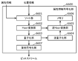
- FIG. 56 is a block diagram of the attribute information coding unit according to the eighth embodiment.
- FIG. 57 is a block diagram of the attribute information decoding unit according to the eighth embodiment.
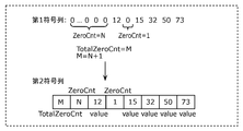
- FIG. 58 is a diagram showing an example of a first code string and a second code string according to the modified example of the eighth embodiment.
- FIG. 59 is a diagram showing a syntax example of attribute information according to a modified example of the eighth embodiment.
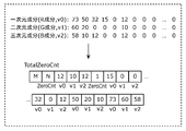
- FIG. 60 is a diagram showing examples of coding coefficients, ZeroCnt and TotalZeroCnt according to the modified example of the eighth embodiment.
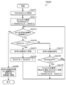
- FIG. 61 is a flowchart of the coding coefficient coding process according to the modified example of the eighth embodiment.
- FIG. 62 is a flowchart of the coding coefficient decoding process according to the modified example of the eighth embodiment.
- FIG. 63 is a diagram showing a syntax example of attribute information according to a modified example of the eighth embodiment.
- FIG. 64 is a block diagram showing the configuration of the three-dimensional data coding apparatus according to the ninth embodiment.
- FIG. 65 is a block diagram showing the configuration of the three-dimensional data decoding device according to the ninth embodiment.
- FIG. 66 is a diagram showing a setting example of LoD according to the ninth embodiment.
- FIG. 67 is a diagram showing an example of the hierarchical structure of RAHT according to the ninth embodiment.
- FIG. 68 is a block diagram of the three-dimensional data coding device according to the ninth embodiment.
- FIG. 69 is a block diagram of the divided portion according to the ninth embodiment.
- FIG. 70 is a block diagram of the attribute information coding unit according to the ninth embodiment.
- FIG. 71 is a block diagram of the three-dimensional data decoding device according to the ninth embodiment.
- FIG. 72 is a block diagram of the attribute information decoding unit according to the ninth embodiment.
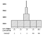
- FIG. 73 is a diagram showing an example of setting the quantization parameter in the tile and slice division according to the ninth embodiment.
- FIG. 74 is a diagram showing a setting example of the quantization parameter according to the ninth embodiment.
- FIG. 75 is a diagram showing a setting example of the quantization parameter according to the ninth embodiment.
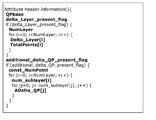
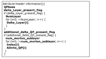
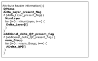
- FIG. 76 is a diagram showing an example of syntax of the attribute information header according to the ninth embodiment.
- FIG. 77 is a diagram showing an example of syntax of the attribute information header according to the ninth embodiment.
- FIG. 78 is a diagram showing a setting example of the quantization parameter according to the ninth embodiment.
- FIG. 79 is a diagram showing an example of syntax of the attribute information header according to the ninth embodiment.
- FIG. 80 is a diagram showing an example of syntax of the attribute information header according to the ninth embodiment.
- FIG. 81 is a flowchart of the three-dimensional data coding process according to the ninth embodiment.
- FIG. 82 is a flowchart of the attribute information coding process according to the ninth embodiment.
- FIG. 83 is a flowchart of the ⁇ QP determination process according to the ninth embodiment.
- FIG. 84 is a flowchart of the three-dimensional data decoding process according to the ninth embodiment.
- FIG. 85 is a flowchart of the attribute information decoding process according to the ninth embodiment.
- FIG. 86 is a block diagram of the attribute information coding unit according to the ninth embodiment.
- FIG. 87 is a block diagram of the attribute information decoding unit according to the ninth embodiment.
- FIG. 88 is a diagram showing a setting example of the quantization parameter according to the ninth embodiment.
- FIG. 89 is a diagram showing an example of syntax of the attribute information header according to the ninth embodiment.
- FIG. 90 is a diagram showing an example of syntax of the attribute information header according to the ninth embodiment.
- FIG. 90 is a diagram showing an example of syntax of the attribute information header according to the ninth embodiment.
- FIG. 91 is a flowchart of the three-dimensional data coding process according to the ninth embodiment.
- FIG. 92 is a flowchart of the attribute information coding process according to the ninth embodiment.
- FIG. 93 is a flowchart of the three-dimensional data decoding process according to the ninth embodiment.
- FIG. 94 is a flowchart of the attribute information decoding process according to the ninth embodiment.
- FIG. 95 is a block diagram of the attribute information coding unit according to the ninth embodiment.
- FIG. 96 is a block diagram of the attribute information decoding unit according to the ninth embodiment.
- FIG. 97 is a diagram showing an example of syntax of the attribute information header according to the ninth embodiment.
- FIG. 98 is a graph showing the relationship between the bit rate and time of coding the bit stream according to the tenth embodiment.
- FIG. 99 is a diagram showing the hierarchical structure of the three-dimensional point cloud according to the tenth embodiment and the number of three-dimensional points belonging to each layer.
- FIG. 100 is a diagram showing a first example of classifying a one-layer three-dimensional point cloud according to the tenth embodiment into sub-layers according to a designated three-dimensional point cloud.
- FIG. 101 is a diagram showing a second example of classifying a one-layer three-dimensional point cloud according to the tenth embodiment into sub-layers with a constant three-dimensional number of points.
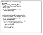
- FIG. 102 shows an example of the syntax of the attribute information header in the second example according to the tenth embodiment.
- FIG. 103 shows another example of the syntax of attribute information in the second example according to the tenth embodiment.
- FIG. 104 is a diagram showing a third example of classifying the one-layer three-dimensional point cloud according to the tenth embodiment into a number of sub-layers different from the planned number.
- FIG. 105 shows an example of the syntax of the attribute information header in the third example according to the tenth embodiment.
- FIG. 106 shows another example of the syntax of the attribute information header in the third example according to the tenth embodiment.
- FIG. 107 is a diagram showing a fourth example of classifying a three-dimensional point cloud of one layer according to the tenth embodiment into sub-layers by a three-dimensional point cloud designated by a ratio (percentage).
- FIG. 108 shows an example of the syntax of the attribute information header in the fourth example according to the tenth embodiment.
- FIG. 105 shows an example of the syntax of the attribute information header in the third example according to the tenth embodiment.
- FIG. 106 shows another example of the syntax of the attribute information header in the third example according to the tenth embodiment.
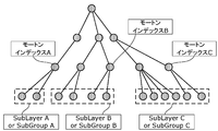
- FIG. 109 is a diagram showing a fifth example of classifying a one-layer three-dimensional point cloud according to the tenth embodiment into sub-layers by Morton index.
- FIG. 110 shows an example of the syntax of the attribute information header in the fifth example according to the tenth embodiment.
- FIG. 111 is a diagram showing a sixth example of classifying the one-layer three-dimensional point cloud according to the tenth embodiment into sub-layers by the Morton index.
- FIG. 112 is a diagram showing a sixth example of classifying the one-layer three-dimensional point cloud according to the tenth embodiment into sub-layers by the Morton index.
- FIG. 110 shows an example of the syntax of the attribute information header in the fifth example according to the tenth embodiment.
- FIG. 111 is a diagram showing a sixth example of classifying the one-layer three-dimensional point cloud according to the tenth embodiment into sub-layers by the Morton index.
- FIG. 112 is a diagram showing a sixth example of classifying the one
- FIG. 113 is a diagram showing a seventh example of classifying a one-layer three-dimensional point cloud according to the tenth embodiment into sub-layers using a residual or a Delta value.
- FIG. 114 is a diagram showing an array of three-dimensional points when arranged in the two-dimensional Morton order according to the tenth embodiment.
- FIG. 115 shows an example of the syntax of the attribute information header in the seventh example according to the tenth embodiment.
- FIG. 116 shows an example of the residual bitstream syntax according to the tenth embodiment.
- FIG. 117 shows an equation for calculating the coding cost according to the tenth embodiment.
- FIG. 118 is a graph showing the relationship between BPP (bits per point) and time according to the tenth embodiment.
- FIG. 119 is a diagram showing that the QP value applied to the coding of the attribute information according to the tenth embodiment is set for each sub-layer.
- FIG. 120 is a diagram showing an eighth example of classifying the three-dimensional point cloud according to the tenth embodiment into sub-layers using a Morton code.
- FIG. 121 shows an example of the syntax of the attribute information header in the eighth example according to the tenth embodiment.
- FIG. 122 is a flowchart of the three-dimensional data coding process according to the tenth embodiment.
- FIG. 123 is a flowchart of the three-dimensional data decoding process according to the tenth embodiment.
- FIG. 124 is a diagram for explaining an example of a three-dimensional space to which the three-dimensional point cloud of the three-dimensional model according to the eleventh embodiment belongs.
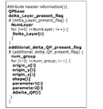
- FIG. 125 shows an example of the syntax of the attribute information header according to the eleventh embodiment.
- FIG. 126 is a diagram for explaining another example of the three-dimensional space to which the three-dimensional point cloud according to the eleventh embodiment belongs.
- FIG. 127 is a diagram for explaining another example of the three-dimensional space to which the three-dimensional point cloud according to the eleventh embodiment belongs.
- FIG. 128 shows an example of the syntax of the attribute information header when the cylindrical three-dimensional space according to the eleventh embodiment is set.
- FIG. 129 is a flowchart showing an example of a process of applying different quantization parameters to each of the three-dimensional spaces according to the eleventh embodiment.
- FIG. 130 is a flowchart showing another example of the process of applying different quantization parameters to each of the three-dimensional spaces according to the eleventh embodiment.
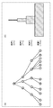
- FIG. 131 is a diagram for explaining a first example of coding of attribute information using RAHT according to the eleventh embodiment.
- FIG. 132 is a diagram for explaining a second example of coding of attribute information using RAHT according to the eleventh embodiment.
- FIG. 133 is a diagram for explaining a third example of coding of attribute information using RAHT according to the eleventh embodiment.
- FIG. 134 is a diagram for explaining a fourth example of coding of attribute information using RAHT according to the eleventh embodiment.
- FIG. 135 is a diagram showing an example of a hierarchical structure (tree structure) of RAHT according to the eleventh embodiment.
- FIG. 136 is a diagram for explaining a fifth example of coding of attribute information using RAHT according to the eleventh embodiment.
- FIG. 137 is a diagram for explaining a sixth example of coding of attribute information using RAHT according to the eleventh embodiment.
- FIG. 138 is a block diagram showing an example of a processing unit that executes the attribute information coding process according to the eleventh embodiment.
- FIG. 140 is a block diagram showing an example of a processing unit that executes a decoding process of the attribute information according to the eleventh embodiment.
- FIG. 141 is a flowchart of the three-dimensional data coding process according to the eleventh embodiment.
- FIG. 142 is a flowchart of the three-dimensional data decoding process according to the eleventh embodiment.
- FIG. 143 is a diagram for explaining a method of transmitting the quantization parameter used for encoding the attribute information according to the twelfth embodiment.
- FIG. 140 is a block diagram showing an example of a processing unit that executes a decoding process of the attribute information according to the eleventh embodiment.
- FIG. 141 is a flowchart of the three-dimensional data coding process according to the eleventh embodiment.
- FIG. 142 is a flowchart of the three-dimensional data decoding process according to the eleventh embodiment.
- FIG. 143 is a diagram for explaining a method of transmitting the quantization parameter used for encoding the attribute information
- FIG. 144 is an example of a flowchart for deriving the QP value applied to the attribute information of the processing target according to the twelfth embodiment.
- FIG. 145 is a flowchart of a method for determining a QP value for each three-dimensional point according to the twelfth embodiment.
- FIG. 146 is an example of a flowchart of a coding method by the three-dimensional data coding device according to the twelfth embodiment.
- FIG. 147 is an example of a flowchart of a decoding method by the three-dimensional data decoding apparatus according to the twelfth embodiment.
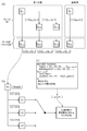
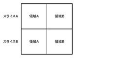
- FIG. 148 is a diagram for explaining an example of the relationship between the slice and the region according to the twelfth embodiment.
- FIG. 149 is a diagram for explaining another example of the relationship between the slice and the region according to the twelfth embodiment.
- FIG. 150 is a diagram for explaining an example of setting an area after dividing the data according to the twelfth embodiment.
- FIG. 151 is a diagram for explaining an example of data division after setting the region according to the twelfth embodiment.
- FIG. 152 is a flowchart showing another example of the three-dimensional data coding process according to the twelfth embodiment.
- FIG. 153 is a flowchart showing another example of the three-dimensional data coding process according to the twelfth embodiment.
- a plurality of attribute information of a plurality of three-dimensional points is encoded using parameters, and the coded plurality of attribute information and a bit including the parameter are included.
- a stream is generated, each of the plurality of attribute information belongs to one or more layers, each of the plurality of three-dimensional points belongs to one or more regions, and the parameter has the reference numeral.
- the parameter to which the attribute information to be encoded belongs is determined according to the hierarchy to which the attribute information to be encoded belongs and the region to which the three-dimensional point having the attribute information to be encoded belongs, and the parameter included in the bit stream is a predetermined reference value. And the first difference value determined for each layer and the second difference value determined for each area.
- the parameter in the bit stream, is indicated by a predetermined reference value, a first difference value determined for each layer, and a second difference value determined for each area.
- the coding efficiency can be improved.
- each of the plurality of attribute information further belongs to one or more slices, and the parameters are determined according to the slice to which the attribute information to be encoded belongs, and are included in the bit stream.
- the parameter may further include a third difference value determined for each slice.
- parameters are set as a predetermined reference value, a first difference value determined for each layer, a second difference value determined for each area, and each slice. Since it is indicated by the third difference value defined in, the coding efficiency can be improved.
- each of the plurality of attribute information further belongs to one or more frames, and the parameter is determined according to the frame to which the attribute information to be encoded belongs, and is included in the bit stream.
- the parameter may further include a fourth difference value determined for each frame.
- the parameters are set to a predetermined reference value, a first difference value determined for each layer, a second difference value determined for each area, and each frame. Since it is indicated by the fourth difference value defined in the above, the coding efficiency can be improved.
- the first region of the one or more regions belongs to the first slice of the one or more slices, and the origin coordinates of the first region are coordinates based on the origin coordinates of the first slice. It may be.
- the origin coordinates of the first region are indicated by the origin coordinates of the first slice and the difference value thereof, the coding efficiency can be improved.
- a plurality of encoded attribute information and parameters are acquired by acquiring a bit stream, and the encoded parameters are obtained using the parameters.
- a plurality of attribute information is decoded, and the plurality of attribute information is attribute information of a plurality of three-dimensional points, and each of the plurality of attribute information belongs to one or more layers, and the plurality of three dimensions are described.
- Each of the points belongs to one or more regions, and the parameter belongs to the hierarchy to which the attribute information to be encoded belongs and the three-dimensional point having the attribute information to be encoded.
- the parameter determined according to the region and included in the bit stream includes a predetermined reference value, a first difference value determined for each layer, and a second difference value determined for each region.
- the three-dimensional data decoding method can correctly decode the attribute information of the three-dimensional point.
- each of the plurality of attribute information further belongs to one or more slices, and the parameters are determined according to the slice to which the attribute information to be decoded belongs and are included in the bit stream.
- the parameter may further include a third difference value determined for each slice.
- the three-dimensional data decoding method can correctly decode the attribute information of the three-dimensional point.
- each of the plurality of attribute information further belongs to one or more frames, and the parameter is determined according to the frame to which the attribute information to be decoded belongs and is included in the bit stream.
- the parameter may further include a fourth difference value determined for each frame.
- the three-dimensional data decoding method can correctly decode the attribute information of the three-dimensional point.
- the first region of the one or more regions belongs to the first slice of the one or more slices, and the origin coordinates of the first region are coordinates based on the origin coordinates of the first slice. It may be.
- the three-dimensional data decoding method can correctly decode the origin coordinates of the first region.
- a recording medium such as a system, method, integrated circuit, computer program or computer-readable CD-ROM, and the system, method, integrated circuit, computer program. And any combination of recording media may be realized.
- FIG. 1 is a diagram showing a configuration of coded three-dimensional data according to the present embodiment.
- the three-dimensional space is divided into a space (SPC) corresponding to a picture in coding a moving image, and three-dimensional data is encoded in units of spaces.
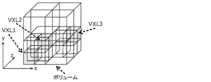
- the space is further divided into volumes (VLM) corresponding to macroblocks and the like in moving image coding, and prediction and conversion are performed in units of VLM.
- the volume includes a plurality of voxels (VXL) which are the smallest units to which the position coordinates are associated.
- VXL voxels
- the prediction is the same as the prediction performed by the two-dimensional image, referring to other processing units, generating the prediction three-dimensional data similar to the processing unit of the processing target, and the prediction three-dimensional data and the processing target. It is to encode the difference from the processing unit. Further, this prediction includes not only spatial prediction that refers to other prediction units at the same time, but also time prediction that refers to prediction units at different times.
- a three-dimensional data coding device (hereinafter, also referred to as a coding device) indicates a point cloud according to the size of a voxel when encoding a three-dimensional space represented by point cloud data such as a point cloud.
- point cloud data such as a point cloud.
- Each point of the above, or a plurality of points contained in the voxel are collectively encoded. If the voxel is subdivided, the three-dimensional shape of the point cloud can be expressed with high accuracy, and if the size of the voxel is increased, the three-dimensional shape of the point cloud can be roughly expressed.
- the three-dimensional data is a point cloud
- the three-dimensional data is not limited to the point cloud and may be any form of three-dimensional data.
- a hierarchical voxel may be used.
- the nth-order layer it may be indicated in order whether or not the sample points exist in the n-1th-order or lower layer (the lower layer of the nth-order layer).
- the n-1th-order layer the lower layer of the nth-order layer.
- the coding device acquires point cloud data using a distance sensor, a stereo camera, a monocular camera, a gyro, an inertial sensor, or the like.
- the space can be an intra space (ISPC) that can be decoded independently, a predictive space (P-SPC) that can be referenced only in one direction, and a bidirectional reference, as in the case of encoding a moving image. It falls into one of at least three predictive structures, including a bidirectional space (B-SPC). Further, the space has two types of time information, a decoding time and a display time.
- ISPC intra space
- P-SPC predictive space
- B-SPC bidirectional space
- the space has two types of time information, a decoding time and a display time.
- GOS Group Of Space
- WLD world
- the spatial area occupied by the world is associated with the absolute position on the earth by GPS or latitude and longitude information. This position information is stored as meta information.
- the meta information may be included in the coded data or may be transmitted separately from the coded data.
- all SPCs may be three-dimensionally adjacent to each other, or there may be SPCs that are not three-dimensionally adjacent to other SPCs.
- processing such as coding, decoding or reference of three-dimensional data included in a processing unit such as GOS, SPC or VLM is also described as simply encoding, decoding or referencing the processing unit.
- the three-dimensional data included in the processing unit includes, for example, at least one set of a spatial position such as three-dimensional coordinates and a characteristic value such as color information.
- a plurality of SPCs in the same GOS or a plurality of VLMs in the same SPC occupy different spaces from each other, but have the same time information (decoding time and display time).
- the SPC that is the first in the decoding order in GOS is I-SPC.
- GOS there are two types of GOS, closed GOS and open GOS.
- the closed GOS is a GOS capable of decoding all the SPCs in the GOS when the decoding is started from the head I-SPC.
- the open GOS some SPCs whose display time is earlier than the first I-SPC in the GOS refer to a different GOS, and decoding cannot be performed only by the GOS.
- WLD may be decoded from the direction opposite to the coding order, and if there is a dependency between GOS, it is difficult to reproduce in the reverse direction. Therefore, in such a case, closed GOS is basically used.
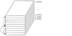
- the GOS has a layer structure in the height direction, and coding or decoding is performed in order from the SPC of the lower layer.
- FIG. 2 is a diagram showing an example of a prediction structure between SPCs belonging to the lowest layer of GOS.
- FIG. 3 is a diagram showing an example of a prediction structure between layers.
- I-SPCs there is one or more I-SPCs in the GOS.
- Objects such as humans, animals, cars, bicycles, traffic lights, and landmark buildings exist in the three-dimensional space, but it is effective to encode the objects, which are particularly small in size, as ISPCs.
- a three-dimensional data decoding device (hereinafter, also referred to as a decoding device) decodes only the I-SPC in the GOS when decoding the GOS with a low processing amount or a high speed.
- the coding device may switch the coding interval or appearance frequency of the I-SPC according to the density of the objects in the WLD.
- the coding device or the decoding device encodes or decodes a plurality of layers in order from the lower layer (layer 1). This makes it possible to raise the priority of data near the ground, which has a larger amount of information for, for example, an autonomous vehicle.
- coded data used in a drone or the like may be coded or decoded in order from the SPC of the upper layer in the height direction in the GOS.
- the coding device or the decoding device may encode or decode a plurality of layers so that the decoding device can roughly grasp the GOS and gradually increase the resolution.
- the coding device or decoding device may encode or decode in the order of layers 3, 8, 1, 9 ...
- static objects or scenes such as buildings or roads
- dynamic objects such as cars or humans
- Object detection is performed separately by extracting feature points from point cloud data or camera images such as stereo cameras.
- the first method is a method of encoding a static object and a dynamic object without distinguishing them.
- the second method is a method of distinguishing between a static object and a dynamic object by identification information.
- GOS is used as an identification unit.
- the GOS including the SPC constituting the static object and the GOS including the SPC constituting the dynamic object are distinguished by the identification information stored in the coded data or separately from the coded data.
- the SPC may be used as the identification unit.
- the SPC including the VLM that constitutes the static object and the SPC that includes the VLM that constitutes the dynamic object are distinguished by the above identification information.
- VLM or VXL may be used as the identification unit.
- the VLM or VXL including the static object and the VLM or VXL including the dynamic object are distinguished by the above identification information.
- the coding device may encode the dynamic object as one or more VLMs or SPCs, and encode the VLM or SPC including the static object and the SPC including the dynamic object as different GOSs. Further, when the size of the GOS is variable according to the size of the dynamic object, the encoding device separately stores the size of the GOS as meta information.
- the coding device may encode the static object and the dynamic object independently of each other, and superimpose the dynamic object on the world composed of the static objects.
- the dynamic object is composed of one or more SPCs, and each SPC is associated with one or more SPCs constituting the static object on which the SPCs are superimposed.
- the dynamic object may be represented by one or more VLMs or VXLs instead of the SPC.
- the coding device may encode the static object and the dynamic object as different streams.
- the coding device may generate a GOS including one or more SPCs constituting the dynamic object. Further, the coding apparatus may set the GOS (GOS_M) including the dynamic object and the GOS of the static object corresponding to the spatial area of GOS_M to the same size (occupy the same spatial area). As a result, the superimposition processing can be performed in units of GOS.
- the P-SPC or B-SPC constituting the dynamic object may refer to the SPC included in a different encoded GOS.
- a reference across the GOS is effective from the viewpoint of compression ratio.
- the above-mentioned first method and the second method may be switched depending on the use of the coded data. For example, when the coded three-dimensional data is used as a map, it is desirable that the dynamic objects can be separated, so the coding device uses the second method. On the other hand, the coding device uses the first method when it is not necessary to separate the dynamic objects when coding the three-dimensional data of an event such as a concert or a sport.
- the decoding time and the display time of the GOS or SPC can be stored in the coded data or as meta information. Moreover, the time information of all static objects may be the same. At this time, the actual decoding time and the display time may be determined by the decoding device. Alternatively, a different value may be assigned to each GOS or SPC as the decoding time, and the same value may be assigned as the display time. Further, like a decoder model in moving image coding such as HEVC's HRD (Hypothetical Reference Decorder), if the decoder has a buffer of a predetermined size and reads a bit stream at a predetermined bit rate according to the decoding time, it can be decoded without failure. A model that guarantees may be introduced.
- HRD Hypothetical Reference Decorder
- the coordinates of the three-dimensional space in the world are represented by three coordinate axes (x-axis, y-axis, and z-axis) that are orthogonal to each other.
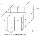
- coding can be performed so that spatially adjacent GOSs are continuous in the coded data.
- the GOS in the xz plane is continuously encoded.
- the y-axis value is updated after the coding of all GOS in a certain xz plane is completed. That is, as the coding progresses, the world extends in the y-axis direction.
- the GOS index number is set in the coding order.
- the three-dimensional space of the world is associated with GPS or geographical absolute coordinates such as latitude and longitude on a one-to-one basis.
- the three-dimensional space may be represented by a position relative to a preset reference position.
- the x-axis, y-axis, and z-axis directions of the three-dimensional space are expressed as direction vectors determined based on latitude, longitude, and the like, and the direction vectors are stored together with coded data as meta information.
- the size of GOS is fixed, and the encoding device stores the size as meta information. Further, the size of the GOS may be switched depending on, for example, whether it is an urban area or indoors or outdoors. That is, the size of the GOS may be switched depending on the amount or nature of the objects that are valuable as information.
- the coding device may adaptively switch the size of the GOS or the interval of the I-SPC in the GOS according to the density of objects and the like in the same world. For example, the coding device reduces the size of the GOS and shortens the interval between I-SPCs in the GOS as the density of objects increases.
- the GOS is subdivided in order to realize random access with fine granularity.
- the 7th to 10th GOSs are located behind the 3rd to 6th GOSs, respectively.
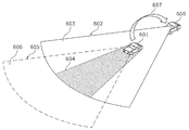
- FIG. 7 is a schematic diagram showing a state of transmission / reception of three-dimensional data 607 between the own vehicle 600 and the peripheral vehicle 601.
- the sensor of the own vehicle 600 When acquiring 3D data using a sensor mounted on the own vehicle 600 (a distance sensor such as a range finder, a stereo camera, or a combination of a plurality of monocular cameras), the sensor of the own vehicle 600 due to an obstacle such as a peripheral vehicle 601 An area within the detection range 602 but where three-dimensional data cannot be created (hereinafter, this is referred to as an occlusion area 604) is generated. Further, the accuracy of the autonomous operation increases as the space for acquiring the three-dimensional data increases, but the sensor detection range of the own vehicle 600 alone is finite.
- a distance sensor such as a range finder, a stereo camera, or a combination of a plurality of monocular cameras
- the sensor detection range 602 of the own vehicle 600 includes an area 603 in which three-dimensional data can be acquired and an occlusion area 604.
- the range in which the own vehicle 600 wants to acquire three-dimensional data includes the sensor detection range 602 of the own vehicle 600 and other areas.
- the sensor detection range 605 of the peripheral vehicle 601 includes an occlusion area 604 and a region 606 not included in the sensor detection range 602 of the own vehicle 600.
- the peripheral vehicle 601 transmits the information detected by the peripheral vehicle 601 to the own vehicle 600.
- the own vehicle 600 acquires the three-dimensional data 607 of the occlusion area 604 and the area 606 other than the sensor detection range 602 of the own vehicle 600 by acquiring the information detected by the peripheral vehicle 601 such as the vehicle in front. Is possible.
- the own vehicle 600 complements the three-dimensional data of the occlusion area 604 and the area 606 outside the sensor detection range by using the information acquired by the peripheral vehicle 601.
- 3D data in the autonomous operation of vehicles or robots is for self-position estimation, detection of surrounding conditions, or both.
- self-position estimation three-dimensional data generated by the own vehicle 600 based on the sensor information of the own vehicle 600 is used.
- the three-dimensional data acquired from the peripheral vehicle 601 is also used to detect the surrounding situation.
- the peripheral vehicle 601 that transmits the three-dimensional data 607 to the own vehicle 600 may be determined according to the state of the own vehicle 600.
- the peripheral vehicle 601 is a front-running vehicle when the own vehicle 600 goes straight, an oncoming vehicle when the own vehicle 600 turns right, and a rear vehicle when the own vehicle 600 reverses.
- the driver of the own vehicle 600 may directly specify the peripheral vehicle 601 for transmitting the three-dimensional data 607 to the own vehicle 600.
- the own vehicle 600 may search for a peripheral vehicle 601 that possesses three-dimensional data in an area that cannot be acquired by the own vehicle 600, which is included in the space in which the three-dimensional data 607 is desired to be acquired.
- the area that cannot be acquired by the own vehicle 600 is an occlusion area 604, an area 606 outside the sensor detection range 602, and the like.
- the own vehicle 600 may specify the occlusion area 604 based on the sensor information of the own vehicle 600. For example, the own vehicle 600 identifies an area within the sensor detection range 602 of the own vehicle 600 where three-dimensional data cannot be created as an occlusion area 604.
- FIG. 8 is a diagram showing an example of three-dimensional data to be transmitted in this case.
- the three-dimensional data 607 transmitted from the vehicle in front is, for example, a point cloud sparse world (SWLD). That is, the preceding vehicle creates WLD three-dimensional data (point cloud) from the information detected by the sensor of the preceding vehicle, and extracts data having a feature amount equal to or greater than the threshold value from the WLD three-dimensional data to SWLD. Create 3D data (point cloud) of. Then, the preceding vehicle transmits the created three-dimensional data of SWLD to the own vehicle 600.
- SWLD point cloud sparse world
- the own vehicle 600 receives the SWLD and merges the received SWLD with the point cloud created by the own vehicle 600.
- the transmitted SWLD has information on absolute coordinates (the position of the SWLD in the coordinate system of the three-dimensional map).
- the own vehicle 600 can realize the merge process by overwriting the point cloud generated by the own vehicle 600 based on the absolute coordinates.
- the SWLD transmitted from the peripheral vehicle 601 is the SWLD of the area 606 outside the sensor detection range 602 of the own vehicle 600 and within the sensor detection range 605 of the peripheral vehicle 601 or the SWLD of the occlusion area 604 for the own vehicle 600. Both SWLDs may be used. Further, the SWLD to be transmitted may be the SWLD in the region of the above SWLDs used by the peripheral vehicle 601 to detect the peripheral situation.
- the peripheral vehicle 601 may change the density of the point cloud to be transmitted according to the communicable time based on the speed difference between the own vehicle 600 and the peripheral vehicle 601. For example, when the speed difference is large and the communicable time is short, the peripheral vehicle 601 can reduce the density (data amount) of the point cloud by extracting three-dimensional points having a large feature amount from the SWLD. Good.
- the detection of the surrounding situation is to determine the presence or absence of people, vehicles, equipment for road construction, etc., identify the type, and detect the position, moving direction, moving speed, and the like. ..
- the own vehicle 600 may acquire the braking information of the peripheral vehicle 601 instead of the three-dimensional data 607 generated by the peripheral vehicle 601 or in addition to the three-dimensional data 607.
- the braking information of the peripheral vehicle 601 is, for example, information indicating that the accelerator or the brake of the peripheral vehicle 601 has been stepped on, or the degree thereof.
- the three-dimensional space is subdivided into random access units in consideration of low-delay communication between vehicles.
- the three-dimensional space is divided into large random access units as compared with the case of inter-vehicle communication.
- the data in the area that tends to be an occlusion area is divided into fine random access units as low-delay data.
- each vehicle Since the importance of the front is increasing when driving at high speed, each vehicle creates a SWLD with a narrow viewing angle in small random access units when driving at high speed.
- the preceding vehicle can reduce the transmission amount by removing the point cloud in that area. Good.
- FIG. 9 is a diagram showing an example of a target space of three-dimensional data to be transmitted to a following vehicle or the like.
- the vehicle 801 uses three-dimensional data such as a point cloud (point cloud) included in a rectangular parallelepiped space 802 having a width W, a height H, and a depth D at a distance L from the vehicle 801 in front of the vehicle 801 for a time of ⁇ t. At intervals, it is sent to the traffic monitoring cloud that monitors the road conditions or to the following vehicle.
- a point cloud point cloud
- the vehicle 801 When a vehicle or a person enters the space 802 from the outside and the three-dimensional data included in the previously transmitted space 802 is changed, the vehicle 801 is about the three-dimensional data of the changed space. Also send.
- FIG. 9 shows an example in which the shape of the space 802 is a rectangular parallelepiped
- the space 802 may include a space on the front road which is a blind spot from the following vehicle, and does not necessarily have to be a rectangular parallelepiped. ..
- the distance L be set to a distance at which the following vehicle that has received the three-dimensional data can safely stop.
- the width W is set to a value larger than at least the width of the lane in which the vehicle 801 is traveling. More preferably, the width W is set to a size that includes adjacent spaces such as left and right lanes or roadside zones.
- the capacity of the three-dimensional data transmitted can be effectively reduced, and communication delay and cost can be reduced. it can.
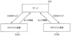
- FIG. 10 is a diagram showing a configuration of a three-dimensional map and a sensor information transmission / reception system according to the present embodiment.
- the system includes a server 901 and client devices 902A and 902B.
- client devices 902A and 902B are not particularly distinguished, they are also referred to as the client devices 902.
- the client device 902 is, for example, an in-vehicle device mounted on a moving body such as a vehicle.
- the server 901 is, for example, a traffic monitoring cloud or the like, and can communicate with a plurality of client devices 902.
- the server 901 transmits a three-dimensional map composed of a point cloud to the client device 902.
- the configuration of the three-dimensional map is not limited to the point cloud, and may represent other three-dimensional data such as a mesh structure.
- the client device 902 transmits the sensor information acquired by the client device 902 to the server 901.
- the sensor information includes, for example, at least one of LiDAR acquisition information, visible light image, infrared image, depth image, sensor position information, and speed information.
- the data sent and received between the server 901 and the client device 902 may be compressed to reduce the data, or may remain uncompressed to maintain the accuracy of the data.
- a three-dimensional compression method based on an octa-tree structure can be used for the point cloud.
- a two-dimensional image compression method can be used for visible light images, infrared images, and depth images.
- the two-dimensional image compression method is, for example, MPEG-4 AVC or HEVC standardized by MPEG.
- the server 901 transmits the three-dimensional map managed by the server 901 to the client device 902 in response to the transmission request of the three-dimensional map from the client device 902.
- the server 901 may transmit the three-dimensional map without waiting for the three-dimensional map transmission request from the client device 902.
- the server 901 may broadcast a three-dimensional map to one or more client devices 902 in a predetermined space.
- the server 901 may transmit a three-dimensional map suitable for the position of the client device 902 to the client device 902 that has received the transmission request once at regular intervals.
- the server 901 may transmit the three-dimensional map to the client device 902 every time the three-dimensional map managed by the server 901 is updated.
- the client device 902 issues a three-dimensional map transmission request to the server 901. For example, when the client device 902 wants to perform self-position estimation during traveling, the client device 902 transmits a three-dimensional map transmission request to the server 901.
- the client device 902 may issue a three-dimensional map transmission request to the server 901.
- the client device 902 may issue a transmission request for the three-dimensional map to the server 901.
- the client device 902 may issue a three-dimensional map transmission request to the server 901.
- the client device 902 may issue a three-dimensional map transmission request to the server 901 before a certain time when the client device 902 goes out. For example, when the client device 902 exists within a predetermined distance from the boundary of the space indicated by the three-dimensional map held by the client device 902, the client device 902 issues a three-dimensional map transmission request to the server 901. You may. If the movement route and movement speed of the client device 902 are known, the time when the client device 902 goes out is predicted from the space shown by the three-dimensional map held by the client device 902. You may.
- the client device 902 may issue a three-dimensional map transmission request to the server 901.
- the client device 902 transmits the sensor information to the server 901 in response to the sensor information transmission request transmitted from the server 901.
- the client device 902 may send the sensor information to the server 901 without waiting for the sensor information transmission request from the server 901. For example, once the client device 902 receives a request for transmitting sensor information from the server 901, the client device 902 may periodically transmit the sensor information to the server 901 for a certain period of time. Further, when the error at the time of alignment between the three-dimensional data created by the client device 902 based on the sensor information and the three-dimensional map obtained from the server 901 is equal to or more than a certain value, the client device 902 is located around the client device 902. It may be determined that the three-dimensional map may have changed, and that fact and the sensor information may be transmitted to the server 901.
- the server 901 issues a sensor information transmission request to the client device 902.
- the server 901 receives the position information of the client device 902 such as GPS from the client device 902.
- the server 901 determines that the client device 902 is approaching a space with little information in the three-dimensional map managed by the server 901 based on the position information of the client device 902
- the server 901 determines that the client device 902 is approaching a space with little information, and the client 901 generates a new three-dimensional map.
- a request for transmitting sensor information is sent to the device 902.
- the server 901 issues a sensor information transmission request when it wants to update the three-dimensional map, when it wants to check the road condition such as when it snows or when there is a disaster, when it wants to check the traffic jam situation, or when it wants to check the incident accident situation. May be good.
- the client device 902 may set the data amount of the sensor information to be transmitted to the server 901 according to the communication state or the band at the time of receiving the transmission request of the sensor information received from the server 901.
- Setting the amount of sensor information data to be transmitted to the server 901 means, for example, increasing or decreasing the data itself, or appropriately selecting a compression method.
- FIG. 11 is a block diagram showing a configuration example of the client device 902.
- the client device 902 receives a three-dimensional map composed of a point cloud or the like from the server 901, and estimates the self-position of the client device 902 from the three-dimensional data created based on the sensor information of the client device 902. Further, the client device 902 transmits the acquired sensor information to the server 901.
- the client device 902 includes a data reception unit 1011, a communication unit 1012, a reception control unit 1013, a format conversion unit 1014, a plurality of sensors 1015, a three-dimensional data creation unit 1016, a three-dimensional image processing unit 1017, and the like. It includes a three-dimensional data storage unit 1018, a format conversion unit 1019, a communication unit 1020, a transmission control unit 1021, and a data transmission unit 1022.
- the data receiving unit 1011 receives the three-dimensional map 1031 from the server 901.
- the three-dimensional map 1031 is data including a point cloud such as WLD or SWLD.
- the three-dimensional map 1031 may include either compressed data or uncompressed data.
- the communication unit 1012 communicates with the server 901 and transmits a data transmission request (for example, a three-dimensional map transmission request) or the like to the server 901.
- a data transmission request for example, a three-dimensional map transmission request
- the reception control unit 1013 exchanges information such as the corresponding format with the communication destination via the communication unit 1012, and establishes communication with the communication destination.
- the format conversion unit 1014 generates the three-dimensional map 1032 by performing format conversion or the like on the three-dimensional map 1031 received by the data receiving unit 1011. Further, the format conversion unit 1014 performs decompression or decoding processing when the three-dimensional map 1031 is compressed or encoded. If the three-dimensional map 1031 is uncompressed data, the format conversion unit 1014 does not perform decompression or decoding processing.
- the plurality of sensors 1015 are a group of sensors that acquire information outside the vehicle on which the client device 902 is mounted, such as a LiDAR, a visible light camera, an infrared camera, or a depth sensor, and generate sensor information 1033.
- the sensor information 1033 is three-dimensional data such as a point cloud (point cloud data) when the sensor 1015 is a laser sensor such as LiDAR.
- the number of sensors 1015 does not have to be plural.
- the three-dimensional data creation unit 1016 creates three-dimensional data 1034 around the own vehicle based on the sensor information 1033. For example, the three-dimensional data creation unit 1016 creates point cloud data with color information around the own vehicle by using the information acquired by LiDAR and the visible light image obtained by the visible light camera.
- the three-dimensional image processing unit 1017 uses the received three-dimensional map 1032 such as a point cloud and the three-dimensional data 1034 around the own vehicle generated from the sensor information 1033 to perform self-position estimation processing of the own vehicle and the like. ..
- the three-dimensional image processing unit 1017 creates three-dimensional data 1035 around the own vehicle by synthesizing the three-dimensional map 1032 and the three-dimensional data 1034, and estimates the self-position using the created three-dimensional data 1035. Processing may be performed.
- the three-dimensional data storage unit 1018 stores the three-dimensional map 1032, the three-dimensional data 1034, the three-dimensional data 1035, and the like.
- the format conversion unit 1019 generates the sensor information 1037 by converting the sensor information 1033 into a format supported by the receiving side.
- the format conversion unit 1019 may reduce the amount of data by compressing or encoding the sensor information 1037. Further, the format conversion unit 1019 may omit the process when it is not necessary to perform the format conversion. Further, the format conversion unit 1019 may control the amount of data to be transmitted according to the designation of the transmission range.
- the communication unit 1020 communicates with the server 901 and receives a data transmission request (sensor information transmission request) and the like from the server 901.
- the transmission control unit 1021 exchanges information such as compatible formats with the communication destination via the communication unit 1020 to establish communication.
- the data transmission unit 1022 transmits the sensor information 1037 to the server 901.
- the sensor information 1037 includes a plurality of sensors such as information acquired by LiDAR, a brightness image acquired by a visible light camera, an infrared image acquired by an infrared camera, a depth image acquired by a depth sensor, sensor position information, and speed information. Contains information acquired by 1015.
- FIG. 12 is a block diagram showing a configuration example of the server 901.
- the server 901 receives the sensor information transmitted from the client device 902, and creates three-dimensional data based on the received sensor information.
- the server 901 updates the three-dimensional map managed by the server 901 by using the created three-dimensional data. Further, the server 901 transmits the updated three-dimensional map to the client device 902 in response to the transmission request of the three-dimensional map from the client device 902.
- the server 901 includes a data reception unit 1111, a communication unit 1112, a reception control unit 1113, a format conversion unit 1114, a three-dimensional data creation unit 1116, a three-dimensional data synthesis unit 1117, and a three-dimensional data storage unit 1118. , A format conversion unit 1119, a communication unit 1120, a transmission control unit 1121, and a data transmission unit 1122.
- the data receiving unit 1111 receives the sensor information 1037 from the client device 902.
- the sensor information 1037 includes, for example, information acquired by LiDAR, a brightness image acquired by a visible light camera, an infrared image acquired by an infrared camera, a depth image acquired by a depth sensor, sensor position information, speed information, and the like.
- the communication unit 1112 communicates with the client device 902 and transmits a data transmission request (for example, a sensor information transmission request) or the like to the client device 902.
- a data transmission request for example, a sensor information transmission request
- the reception control unit 1113 exchanges information such as the corresponding format with the communication destination via the communication unit 1112 to establish communication.
- the format conversion unit 1114 When the received sensor information 1037 is compressed or encoded, the format conversion unit 1114 generates the sensor information 1132 by performing decompression or decoding processing. If the sensor information 1037 is uncompressed data, the format conversion unit 1114 does not perform decompression or decoding processing.
- the three-dimensional data creation unit 1116 creates three-dimensional data 1134 around the client device 902 based on the sensor information 1132. For example, the three-dimensional data creation unit 1116 creates point cloud data with color information around the client device 902 using the information acquired by LiDAR and the visible light image obtained by the visible light camera.
- the three-dimensional data synthesis unit 1117 updates the three-dimensional map 1135 by synthesizing the three-dimensional data 1134 created based on the sensor information 1132 with the three-dimensional map 1135 managed by the server 901.
- the three-dimensional data storage unit 1118 stores the three-dimensional map 1135 and the like.
- the format conversion unit 1119 generates the 3D map 1031 by converting the 3D map 1135 into a format supported by the receiving side.
- the format conversion unit 1119 may reduce the amount of data by compressing or encoding the three-dimensional map 1135. Further, the format conversion unit 1119 may omit the process when it is not necessary to perform the format conversion. Further, the format conversion unit 1119 may control the amount of data to be transmitted according to the designation of the transmission range.
- the communication unit 1120 communicates with the client device 902 and receives a data transmission request (three-dimensional map transmission request) or the like from the client device 902.
- the transmission control unit 1121 exchanges information such as the corresponding format with the communication destination via the communication unit 1120 to establish communication.
- the data transmission unit 1122 transmits the three-dimensional map 1031 to the client device 902.
- the three-dimensional map 1031 is data including a point cloud such as WLD or SWLD.
- the three-dimensional map 1031 may include either compressed data or uncompressed data.
- FIG. 13 is a flowchart showing an operation when the client device 902 acquires a three-dimensional map.
- the client device 902 requests the server 901 to transmit a three-dimensional map (point cloud, etc.) (S1001). At this time, the client device 902 may request the server 901 to transmit a three-dimensional map related to the position information by transmitting the position information of the client device 902 obtained by GPS or the like together.
- a three-dimensional map point cloud, etc.
- the client device 902 receives the three-dimensional map from the server 901 (S1002). If the received 3D map is compressed data, the client device 902 decodes the received 3D map to generate an uncompressed 3D map (S1003).
- the client device 902 creates three-dimensional data 1034 around the client device 902 from the sensor information 1033 obtained by the plurality of sensors 1015 (S1004).
- the client device 902 estimates the self-position of the client device 902 using the three-dimensional map 1032 received from the server 901 and the three-dimensional data 1034 created from the sensor information 1033 (S1005).
- FIG. 14 is a flowchart showing an operation at the time of transmission of sensor information by the client device 902.
- the client device 902 receives the sensor information transmission request from the server 901 (S1011).
- the client device 902 transmits the sensor information 1037 to the server 901 (S1012).
- the sensor information 1033 includes a plurality of information obtained by the plurality of sensors 1015
- the client device 902 may generate the sensor information 1037 by compressing each information by a compression method suitable for each information. Good.
- FIG. 15 is a flowchart showing an operation when the server 901 acquires sensor information.
- the server 901 requests the client device 902 to transmit the sensor information (S1021).
- the server 901 receives the sensor information 1037 transmitted from the client device 902 in response to the request (S1022).
- the server 901 creates three-dimensional data 1134 using the received sensor information 1037 (S1023).
- the server 901 reflects the created three-dimensional data 1134 on the three-dimensional map 1135 (S1024).
- FIG. 16 is a flowchart showing the operation when the server 901 transmits the three-dimensional map.
- the server 901 receives a three-dimensional map transmission request from the client device 902 (S1031).
- the server 901 that has received the three-dimensional map transmission request transmits the three-dimensional map 1031 to the client device 902 (S1032).
- the server 901 may extract a three-dimensional map in the vicinity thereof according to the position information of the client device 902 and transmit the extracted three-dimensional map.
- the server 901 may compress the three-dimensional map composed of the point cloud by using, for example, a compression method based on an octree structure, and transmit the compressed three-dimensional map.
- the server 901 creates three-dimensional data 1134 near the position of the client device 902 using the sensor information 1037 received from the client device 902. Next, the server 901 calculates the difference between the three-dimensional data 1134 and the three-dimensional map 1135 by matching the created three-dimensional data 1134 with the three-dimensional map 1135 of the same area managed by the server 901. .. When the difference is equal to or greater than a predetermined threshold value, the server 901 determines that some abnormality has occurred in the vicinity of the client device 902. For example, when land subsidence occurs due to a natural disaster such as an earthquake, a large difference occurs between the 3D map 1135 managed by the server 901 and the 3D data 1134 created based on the sensor information 1037. Can be considered.
- the sensor information 1037 may include information indicating at least one of the sensor type, the sensor performance, and the sensor model number. Further, a class ID or the like corresponding to the performance of the sensor may be added to the sensor information 1037. For example, when the sensor information 1037 is the information acquired by LiDAR, the sensor capable of acquiring information with an accuracy of several mm is class 1, the sensor capable of acquiring information with an accuracy of several cm is class 2, and the sensor is united with several meters. As in class 3, it is conceivable to assign an identifier to the performance of the sensor that can acquire information with accuracy. Further, the server 901 may estimate the performance information of the sensor and the like from the model number of the client device 902.
- the server 901 may determine the sensor spec information from the vehicle type of the vehicle. In this case, the server 901 may acquire information on the vehicle type of the vehicle in advance, or the sensor information may include the information. Further, the server 901 may switch the degree of correction for the three-dimensional data 1134 created by using the sensor information 1037 by using the acquired sensor information 1037. For example, if the sensor performance is high accuracy (class 1), the server 901 does not make corrections to the three-dimensional data 1134. When the sensor performance is low accuracy (class 3), the server 901 applies a correction to the three-dimensional data 1134 according to the accuracy of the sensor. For example, in the server 901, the lower the accuracy of the sensor, the stronger the degree (strength) of the correction.
- the server 901 may issue a sensor information transmission request to a plurality of client devices 902 in a certain space at the same time.
- the server 901 receives a plurality of sensor information from the plurality of client devices 902, it is not necessary to use all the sensor information for creating the three-dimensional data 1134.
- the sensor to be used depends on the performance of the sensor. Information may be selected.
- the server 901 selects highly accurate sensor information (class 1) from a plurality of received sensor information, and creates 3D data 1134 using the selected sensor information. You may.
- the server 901 is not limited to a server such as a traffic monitoring cloud, and may be another client device (vehicle-mounted).
- FIG. 17 is a diagram showing a system configuration in this case.
- the client device 902C issues a sensor information transmission request to the nearby client device 902A, and acquires the sensor information from the client device 902A. Then, the client device 902C creates three-dimensional data using the acquired sensor information of the client device 902A, and updates the three-dimensional map of the client device 902C. As a result, the client device 902C can generate a three-dimensional map of the space that can be acquired from the client device 902A by utilizing the performance of the client device 902C. For example, it is considered that such a case occurs when the performance of the client device 902C is high.
- the client device 902A that provided the sensor information is given the right to acquire the highly accurate three-dimensional map generated by the client device 902C.
- the client device 902A receives a highly accurate 3D map from the client device 902C in accordance with its rights.
- the client device 902C may issue a request for transmitting sensor information to a plurality of nearby client devices 902 (client device 902A and client device 902B).
- client device 902A and client device 902B client devices 902
- the client device 902C can create three-dimensional data using the sensor information obtained by the high-performance sensor.
- FIG. 18 is a block diagram showing the functional configurations of the server 901 and the client device 902.
- the server 901 includes, for example, a three-dimensional map compression / decoding processing unit 1201 that compresses and decodes a three-dimensional map, and a sensor information compression / decoding processing unit 1202 that compresses and decodes sensor information.
- the client device 902 includes a three-dimensional map decoding processing unit 1211 and a sensor information compression processing unit 1212.
- the three-dimensional map decoding processing unit 1211 receives the encoded data of the compressed three-dimensional map, decodes the encoded data, and acquires the three-dimensional map.
- the sensor information compression processing unit 1212 compresses the sensor information itself instead of the three-dimensional data created from the acquired sensor information, and transmits the compressed sensor information encoded data to the server 901.
- the client device 902 may internally hold a processing unit (device or LSI) that performs a process of decoding a three-dimensional map (point cloud, etc.), and the three-dimensional data of the three-dimensional map (point cloud, etc.). It is not necessary to hold a processing unit that performs processing for compressing. As a result, the cost and power consumption of the client device 902 can be suppressed.
- the client device 902 is mounted on the moving body, and is obtained from the sensor information 1033 indicating the surrounding condition of the moving body obtained by the sensor 1015 mounted on the moving body. Create peripheral three-dimensional data 1034.
- the client device 902 estimates the self-position of the moving body using the created three-dimensional data 1034.
- the client device 902 transmits the acquired sensor information 1033 to the server 901 or another mobile body 902.
- the client device 902 transmits the sensor information 1033 to the server 901 and the like.
- the amount of data to be transmitted can be reduced as compared with the case where three-dimensional data is transmitted.
- the processing amount of the client device 902 can be reduced. Therefore, the client device 902 can reduce the amount of data to be transmitted or simplify the configuration of the device.
- the client device 902 further transmits a three-dimensional map transmission request to the server 901, and receives the three-dimensional map 1031 from the server 901. In estimating the self-position, the client device 902 estimates the self-position using the three-dimensional data 1034 and the three-dimensional map 1032.
- the sensor information 1033 includes at least one of the information obtained by the laser sensor, the luminance image, the infrared image, the depth image, the position information of the sensor, and the speed information of the sensor.
- the sensor information 1033 includes information indicating the performance of the sensor.
- the client device 902 encodes or compresses the sensor information 1033, and in transmitting the sensor information, transmits the encoded or compressed sensor information 1037 to the server 901 or another mobile body 902. According to this, the client device 902 can reduce the amount of data to be transmitted.
- the client device 902 includes a processor and a memory, and the processor uses the memory to perform the above processing.
- the server 901 can communicate with the client device 902 mounted on the mobile body, and the sensor information 1037 indicating the surrounding situation of the mobile body obtained by the sensor 1015 mounted on the mobile body is obtained. Is received from the client device 902. The server 901 creates three-dimensional data 1134 around the moving body from the received sensor information 1037.
- the server 901 creates the three-dimensional data 1134 using the sensor information 1037 transmitted from the client device 902. As a result, there is a possibility that the amount of data to be transmitted can be reduced as compared with the case where the client device 902 transmits three-dimensional data. Further, since it is not necessary for the client device 902 to perform processing such as compression or coding of three-dimensional data, the processing amount of the client device 902 can be reduced. Therefore, the server 901 can reduce the amount of data to be transmitted or simplify the configuration of the device.
- the server 901 further transmits a transmission request for sensor information to the client device 902.
- the server 901 updates the three-dimensional map 1135 using the created three-dimensional data 1134, and sends the three-dimensional map 1135 to the client device 902 in response to the transmission request of the three-dimensional map 1135 from the client device 902. Send.
- the sensor information 1037 includes at least one of the information obtained by the laser sensor, the luminance image, the infrared image, the depth image, the position information of the sensor, and the speed information of the sensor.
- the sensor information 1037 includes information indicating the performance of the sensor.
- the server 901 further corrects the three-dimensional data according to the performance of the sensor. According to this, the three-dimensional data creation method can improve the quality of the three-dimensional data.
- the server 901 receives a plurality of sensor information 1037 from the plurality of client devices 902, and based on a plurality of information indicating the performance of the sensor included in the plurality of sensor information 1037, the server 901 receives three-dimensional data 1134.
- the sensor information 1037 used for creating the above is selected. According to this, the server 901 can improve the quality of the three-dimensional data 1134.
- the server 901 decodes or decompresses the received sensor information 1037, and creates three-dimensional data 1134 from the decoded or decompressed sensor information 1132. According to this, the server 901 can reduce the amount of data to be transmitted.
- the server 901 includes a processor and a memory, and the processor uses the memory to perform the above processing.
- FIG. 19 is a diagram showing a configuration of a system according to the present embodiment.
- the system shown in FIG. 19 includes a server 2001, a client device 2002A, and a client device 2002B.
- the client device 2002A and the client device 2002B are mounted on a moving body such as a vehicle, and transmit sensor information to the server 2001.
- the server 2001 transmits a three-dimensional map (point cloud) to the client device 2002A and the client device 2002B.
- the client device 2002A includes a sensor information acquisition unit 2011, a storage unit 2012, and a data transmission availability determination unit 2013.
- the configuration of the client device 2002B is also the same. Further, in the following, when the client device 2002A and the client device 2002B are not particularly distinguished, they are also described as the client device 2002.
- FIG. 20 is a flowchart showing the operation of the client device 2002 according to the present embodiment.
- the sensor information acquisition unit 2011 acquires various sensor information using a sensor (sensor group) mounted on the moving body. That is, the sensor information acquisition unit 2011 acquires sensor information indicating the surrounding condition of the moving body, which is obtained by the sensor (sensor group) mounted on the moving body. Further, the sensor information acquisition unit 2011 stores the acquired sensor information in the storage unit 2012.
- This sensor information includes at least one of LiDAR acquisition information, visible light image, infrared image and depth image. Further, the sensor information may include at least one of sensor position information, speed information, acquisition time information, and acquisition location information.
- the sensor position information indicates the position of the sensor from which the sensor information has been acquired.
- the velocity information indicates the velocity of the moving object when the sensor acquires the sensor information.
- the acquisition time information indicates the time when the sensor information is acquired by the sensor.
- the acquisition location information indicates the position of the moving body or the sensor when the sensor information is acquired by the sensor.
- the data transmission availability determination unit 2013 determines whether the mobile body (client device 2002) exists in an environment in which the sensor information can be transmitted to the server 2001 (S2002). For example, the data transmission availability determination unit 2013 may specify the location and time of the client device 2002 by using information such as GPS, and determine whether or not the data can be transmitted. In addition, the data transmission availability determination unit 2013 may determine whether or not data can be transmitted depending on whether or not it can be connected to a specific access point.
- the client device 2002 determines that the moving body exists in an environment in which the sensor information can be transmitted to the server 2001 (Yes in S2002), the client device 2002 transmits the sensor information to the server 2001 (S2003). That is, when the client device 2002 is in a situation where the sensor information can be transmitted to the server 2001, the client device 2002 transmits the held sensor information to the server 2001.
- a millimeter-wave access point capable of high-speed communication is installed at an intersection or the like.
- the sensor information held by the client device 2002 is transmitted to the server 2001 at high speed by using millimeter wave communication.
- the client device 2002 deletes the sensor information transmitted to the server 2001 from the storage unit 2012 (S2004).
- the client device 2002 may delete the sensor information when the sensor information not transmitted to the server 2001 satisfies a predetermined condition.
- the client device 2002 may delete the sensor information from the storage unit 2012 when the acquisition time of the sensor information to be held is older than a certain time before the current time. That is, the client device 2002 may delete the sensor information from the storage unit 2012 when the difference between the time when the sensor information is acquired by the sensor and the current time exceeds a predetermined time. Further, the client device 2002 may delete the sensor information from the storage unit 2012 when the acquisition location of the sensor information to be held is more than a certain distance from the current position.
- the sensor information May be deleted from the storage unit 2012.
- the capacity of the storage unit 2012 of the client device 2002 can be suppressed.
- the client device 2002 repeats the processes after step S2001.
- the client device 2002 ends the process.
- the client device 2002 may select the sensor information to be transmitted to the server 2001 according to the communication status. For example, when high-speed communication is possible, the client device 2002 preferentially transmits sensor information (for example, LiDAR acquisition information) having a large size held in the storage unit 2012. Further, when high-speed communication is difficult, the client device 2002 transmits sensor information (for example, a visible light image) having a small size and a high priority held in the storage unit 2012. As a result, the client device 2002 can efficiently transmit the sensor information held in the storage unit 2012 to the server 2001 according to the network conditions.
- sensor information for example, LiDAR acquisition information
- sensor information for example, a visible light image
- the client device 2002 may acquire the time information indicating the current time and the location information indicating the current location from the server 2001. Further, the client device 2002 may determine the acquisition time and acquisition location of the sensor information based on the acquired time information and location information. That is, the client device 2002 may acquire the time information from the server 2001 and generate the acquisition time information using the acquired time information. Further, the client device 2002 may acquire the location information from the server 2001 and generate the acquisition location information using the acquired location information.
- the server 2001 and the client device 2002 synchronize the time using a mechanism such as NTP (Network Time Protocol) or PTP (Precision Time Protocol).
- NTP Network Time Protocol
- PTP Precision Time Protocol
- the client device 2002 can acquire accurate time information.
- the server 2001 can handle the sensor information indicating the synchronized time.
- the time synchronization mechanism may be any method other than NTP or PTP.
- GPS information may be used as the time information and location information.
- the server 2001 may acquire sensor information from a plurality of client devices 2002 by designating a time or place. For example, in the event of an accident, the server 2001 broadcasts a sensor information transmission request to a plurality of client devices 2002 by designating the time and place of the accident in order to search for a client in the vicinity thereof. Then, the client device 2002 having the sensor information of the corresponding time and place transmits the sensor information to the server 2001. That is, the client device 2002 receives the sensor information transmission request including the designated information for designating the place and time from the server 2001. The client device 2002 determines that the storage unit 2012 stores the sensor information obtained at the place and time indicated by the designated information, and that the moving body exists in an environment in which the sensor information can be transmitted to the server 2001.
- the sensor information obtained at the place and time indicated by the designated information is transmitted to the server 2001.
- the server 2001 can acquire sensor information related to the occurrence of an accident from a plurality of client devices 2002 and use it for accident analysis and the like.
- the client device 2002 may refuse to transmit the sensor information when it receives the sensor information transmission request from the server 2001. Further, the client device 2002 may set in advance which sensor information among the plurality of sensor information can be transmitted. Alternatively, the server 2001 may inquire of the client device 2002 whether or not the sensor information can be transmitted each time.
- points may be given to the client device 2002 that has transmitted the sensor information to the server 2001. These points can be used to pay, for example, gasoline purchase costs, EV (Electric Vehicle) charging costs, highway tolls, or rental car costs.
- the server 2001 may delete the information for identifying the client device 2002 that is the source of the sensor information. For example, this information is information such as the network address of the client device 2002.
- the sensor information can be anonymized, so that the user of the client device 2002 can safely transmit the sensor information from the client device 2002 to the server 2001.
- the server 2001 may be composed of a plurality of servers. For example, by sharing sensor information among a plurality of servers, even if one server fails, another server can communicate with the client device 2002. As a result, it is possible to avoid stopping the service due to a server failure.
- the designated location specified in the sensor information transmission request indicates the position where the accident occurred, and may differ from the position of the client device 2002 at the designated time specified in the sensor information transmission request. Therefore, the server 2001 can request the client device 2002 existing in the range to acquire information by designating a range such as within XXm in the vicinity as the designated place. Similarly, for the designated time, the server 2001 may specify a range such as within N seconds before and after a certain time. As a result, the server 2001 can acquire the sensor information from the client device 2002 that exists at "time: t-N to t + N, location: within XXm from the absolute position S". When transmitting three-dimensional data such as LiDAR, the client device 2002 may transmit the data generated immediately after the time t.
- three-dimensional data such as LiDAR
- the server 2001 may separately specify, as the designated location, the information indicating the location of the client device 2002 for which the sensor information is to be acquired and the location where the sensor information is desired. For example, the server 2001 specifies that the sensor information including at least the range from the absolute position S to YYm is acquired from the client device 2002 existing within XXm from the absolute position S.
- the client device 2002 selects the 3D data of one or more randomly accessible units so as to include at least the sensor information in the specified range.
- the client device 2002 may transmit a plurality of time-consecutive image data including at least a frame immediately before or after the time t.
- the client device 2002 uses a network to be used according to the priority notified from the server 2001. You may choose. Alternatively, the client device 2002 itself may select a network that can secure an appropriate bandwidth based on the size of the transmitted data. Alternatively, the client device 2002 may select a network to be used based on the cost for data transmission and the like. Further, the transmission request from the server 2001 may include information indicating a transmission deadline, such as transmission when the client device 2002 can start transmission by time T. The server 2001 may issue a transmission request again if sufficient sensor information cannot be acquired within the deadline.
- a transmission deadline such as transmission when the client device 2002 can start transmission by time T.
- the sensor information may include header information indicating the characteristics of the sensor data together with the compressed or uncompressed sensor data.
- the client device 2002 may transmit the header information to the server 2001 via a physical network or communication protocol different from the sensor data. For example, the client device 2002 transmits the header information to the server 2001 prior to the transmission of the sensor data.
- the server 2001 determines whether or not to acquire the sensor data of the client device 2002 based on the analysis result of the header information.
- the header information may include information indicating the point cloud acquisition density, elevation angle, or frame rate of LiDAR, or the resolution, signal-to-noise ratio, or frame rate of a visible light image. As a result, the server 2001 can acquire the sensor information from the client device 2002 having the sensor data of the determined quality.
- the client device 2002 acquires the sensor information indicating the surrounding situation of the moving body, which is mounted on the moving body and obtained by the sensor mounted on the moving body, and stores the sensor information in the storage unit 2012. ..
- the client device 2002 determines whether the moving body exists in an environment capable of transmitting sensor information to the server 2001, and if it determines that the moving body exists in an environment capable of transmitting sensor information to the server, the client device 2002 transmits the sensor information to the server 2001. Send to.
- the client device 2002 further creates three-dimensional data around the moving body from the sensor information, and estimates the self-position of the moving body using the created three-dimensional data.
- the client device 2002 further transmits a three-dimensional map transmission request to the server 2001, and receives the three-dimensional map from the server 2001.
- the client device 2002 estimates the self-position by using the three-dimensional data and the three-dimensional map in the estimation of the self-position.
- processing by the client device 2002 may be realized as an information transmission method in the client device 2002.
- the client device 2002 includes a processor and a memory, and the processor may perform the above processing using the memory.
- FIG. 21 is a diagram showing a configuration of a sensor information collection system according to the present embodiment.
- the sensor information collection system according to the present embodiment includes a terminal 2021A, a terminal 2021B, a communication device 2022A, a communication device 2022B, a network 2023, a data collection server 2024, and a map server 2025.
- the client device 2026 and the like.
- the terminal 2021A and the terminal 2021B are not particularly distinguished, they are also described as the terminal 2021.
- the communication device 2022A and the communication device 2022B are not particularly distinguished, they are also described as the communication device 2022.
- the data collection server 2024 collects data such as sensor data obtained by the sensor included in the terminal 2021 as position-related data associated with the position in the three-dimensional space.
- the sensor data is, for example, data acquired by using a sensor included in the terminal 2021 such as a state around the terminal 2021 or an internal state of the terminal 2021.
- the terminal 2021 transmits sensor data collected from one or more sensor devices at a position capable of directly communicating with the terminal 2021 or relaying one or a plurality of relay devices by the same communication method to the data collection server 2024. Send.
- the data included in the position-related data may include, for example, information indicating the operation status of the terminal itself or the device included in the terminal, the operation log, the usage status of the service, and the like. Further, the data included in the position-related data may include information in which the identifier of the terminal 2021 is associated with the position or movement route of the terminal 2021.
- the information indicating the position included in the position-related data is associated with the information indicating the position in the three-dimensional data such as the three-dimensional map data.
- the details of the information indicating the position will be described later.
- the position-related data includes the above-mentioned time information and the attributes of the data included in the position-related data, or information indicating the type of sensor (for example, model number) that generated the data, in addition to the position information which is the information indicating the position. It may contain at least one of.
- the position information and the time information may be stored in the header area of the position-related data or the header area of the frame for storing the position-related data. Further, the position information and the time information may be transmitted and / or stored separately from the position-related data as metadata associated with the position-related data.
- the map server 2025 is connected to the network 2023, for example, and transmits three-dimensional data such as three-dimensional map data in response to a request from another device such as the terminal 2021. Further, as described in each of the above-described embodiments, the map server 2025 may have a function of updating three-dimensional data by using the sensor information transmitted from the terminal 2021.
- the data collection server 2024 is connected to the network 2023, for example, collects position-related data from another device such as the terminal 2021, and stores the collected position-related data in a storage device inside or in another server. Further, the data collection server 2024 transmits the collected position-related data or the metadata of the three-dimensional map data generated based on the position-related data to the terminal 2021 in response to the request from the terminal 2021.
- Network 2023 is a communication network such as the Internet.
- the terminal 2021 is connected to the network 2023 via the communication device 2022.
- the communication device 2022 communicates with the terminal 2021 while switching between one communication method or a plurality of communication methods.
- the communication device 2022 is, for example, (1) a base station such as LTE (Long Term Evolution), (2) an access point (AP) such as WiFi or millimeter wave communication, and (3) LPWA such as SIGFOX, LoRaWAN or Wi-SUN. (Low Power Wide Area)
- a communication satellite that communicates using a network gateway or (4) a satellite communication method such as DVB-S2.
- the base station may communicate with the terminal 2021 by a method classified into LPWA such as NB-IoT (Narrow Band-IoT) or LTE-M, or may switch between these methods and the terminal 2021. Communication may be performed.
- LPWA Low Band-IoT
- LTE-M Long Term Evolution
- Communication may be performed.
- the terminal 2021 has a function of communicating with a communication device 2022 that uses two types of communication methods, and a communication device that uses any of these communication methods, or is a plurality of these communication methods and a direct communication partner.
- a communication device 2022 that uses two types of communication methods
- a communication device that uses any of these communication methods, or is a plurality of these communication methods and a direct communication partner.
- An example is given in the case of communicating with the map server 2025 or the data collection server 2024 while switching 2022, but the configuration of the sensor information collection system and the terminal 2021 is not limited to this.
- the terminal 2021 may not have a communication function in a plurality of communication methods, but may have a function of communicating in any one communication method.
- the terminal 2021 may support three or more communication methods. Further, the corresponding communication method may be different for each terminal 2021.
- the terminal 2021 includes, for example, the configuration of the client device 902 shown in FIG.
- the terminal 2021 estimates the position such as its own position using the received three-dimensional data. Further, the terminal 2021 generates position-related data by associating the sensor data acquired from the sensor with the position information obtained by the position estimation process.
- the position information added to the position-related data indicates, for example, the position in the coordinate system used in the three-dimensional data.
- the position information is a coordinate value represented by a value of latitude and longitude.
- the terminal 2021 may include the coordinate value as well as the information indicating the coordinate system that is the reference of the coordinate value and the three-dimensional data used for the position estimation in the position information.
- the coordinate values may include altitude information.
- the position information may be associated with a unit of data or a unit of space that can be used for coding the three-dimensional data described above.
- This unit is, for example, WLD, GOS, SPC, VLM, VXL, or the like.
- the position information is represented by an identifier for specifying a data unit such as an SPC corresponding to the position-related data.
- the position information is information indicating three-dimensional data in which the three-dimensional space including the data unit such as SPC is encoded, or details in the SPC. It may include information indicating a different position.
- the information indicating the three-dimensional data is, for example, a file name of the three-dimensional data.
- the system generates the position-related data associated with the position information based on the position estimation using the three-dimensional data, so that the self-position of the client device (terminal 2021) acquired by GPS can be used. It is possible to add position information to the sensor information with higher accuracy than when the based position information is added to the sensor information. As a result, even when the position-related data is used by another device in another service, the position corresponding to the position-related data can be more accurately specified in the real space by performing the position estimation based on the same three-dimensional data. There is a possibility that it can be done.
- the data transmitted from the terminal 2021 is the position-related data
- the data transmitted from the terminal 2021 may be data not associated with the position information.
- the transmission / reception of the three-dimensional data or the sensor data described in the other embodiment may be performed via the network 2023 described in the present embodiment.
- the position information added to the position-related data may be information indicating a position relative to a feature point in the three-dimensional data.
- the feature point that serves as a reference for the position information is, for example, a feature point encoded as SWLD and notified to the terminal 2021 as three-dimensional data.
- the information indicating the relative position with respect to the feature point is represented by, for example, a vector from the feature point to the point indicated by the position information, and may be information indicating the direction and distance from the feature point to the point indicated by the position information.
- the information indicating the relative position with respect to the feature point may be information indicating the amount of displacement of each of the X-axis, Y-axis, and Z-axis from the feature point to the point indicated by the position information.
- the information indicating the relative position with respect to the feature point may be information indicating the distance from each of the three or more feature points to the point indicated by the position information.
- the relative position may not be the relative position of the point indicated by the position information expressed with respect to each feature point, but may be the relative position of each feature point expressed with reference to the point indicated by the position information.
- An example of position information based on a relative position with respect to a feature point includes information for specifying a reference feature point and information indicating a relative position of a point indicated by the position information with respect to the feature point.
- the information indicating the relative position with respect to the feature point includes the coordinate axes used for deriving the relative position and the information indicating the type of the three-dimensional data. Alternatively, it may include information indicating the magnitude (scale, etc.) of the value of the information indicating the relative position per unit amount.
- the position information may include information indicating a relative position with respect to each feature point for a plurality of feature points.
- the terminal 2021 that tries to specify the position indicated by the position information in the real space has the position information from the position of the feature point estimated from the sensor data for each feature point.
- the candidate points of the positions indicated by may be calculated, and the points obtained by averaging the calculated plurality of candidate points may be determined to be the points indicated by the position information. According to this configuration, the influence of an error when estimating the position of a feature point from the sensor data can be reduced, so that the estimation accuracy of the point indicated by the position information in the real space can be improved.
- the position information includes information indicating a relative position with respect to a plurality of feature points, even if there is a feature point that cannot be detected due to restrictions such as the type or performance of the sensor included in the terminal 2021, any of the plurality of feature points. If even one of them can be detected, the value of the point indicated by the position information can be estimated.
- a point that can be identified from the sensor data can be used.
- the points that can be identified from the sensor data are, for example, points within a region or points that satisfy predetermined conditions for feature point detection, such as the above-mentioned three-dimensional feature amount or feature amount of visible light data being equal to or greater than a threshold value.
- a marker installed in the real space may be used as a feature point.
- the marker may be detected and its position can be specified from the data acquired by using a sensor such as LiDER or a camera.
- the marker is represented by a change in color or brightness value (reflectance), or a three-dimensional shape (unevenness, etc.).
- a coordinate value indicating the position of the marker, a two-dimensional code or a barcode generated from the identifier of the marker, or the like may be used.
- a light source that transmits an optical signal may be used as a marker.
- a light source of an optical signal is used as a marker, not only information for acquiring a position such as a coordinate value or an identifier but also other data may be transmitted by the optical signal.
- the optical signal is connected to the content of the service according to the position of the marker, an address such as a url for acquiring the content, or an identifier of the wireless communication device for receiving the provision of the service, and the wireless communication device. It may include information indicating a wireless communication method for the purpose.
- the terminal 2021 grasps the correspondence relationship of feature points between different data by using, for example, an identifier commonly used between data or information or a table indicating the correspondence relationship of feature points between data. Further, when there is no information indicating the correspondence between the feature points, the terminal 2021 is the feature at the closest distance when the coordinates of the feature points in one three-dimensional data are converted to the positions in the other three-dimensional data space. A point may be determined to be a corresponding feature point.
- the position information based on the relative position described above is used, even between terminals 2021 or services that use different three-dimensional data, they are included in each three-dimensional data or associated with each three-dimensional data.
- the position indicated by the position information can be specified or estimated based on a common feature point. As a result, it becomes possible to identify or estimate the same position with higher accuracy between terminals 2021 or services that use different three-dimensional data.
- the data collection server 2024 may transfer the received position-related data to another data server.
- the data collection server 2024 determines to which data server the received position-related data is to be transferred, and transfers the position-related data to the data server determined as the transfer destination.
- the data collection server 2024 determines the transfer destination based on, for example, the determination rule of the transfer destination server preset in the data collection server 2024.
- the determination rule of the transfer destination server is set, for example, in a transfer destination table in which the identifier associated with each terminal 2021 and the data server of the transfer destination are associated with each other.
- the terminal 2021 adds an identifier associated with the terminal 2021 to the position-related data to be transmitted and transmits the data to the data collection server 2024.
- the data collection server 2024 specifies the data server of the transfer destination corresponding to the identifier added to the position-related data based on the determination rule of the transfer destination server using the transfer destination table or the like, and the position-related data is specified. Send to the data server. Further, the determination rule of the transfer destination server may be specified by the determination condition using the time or place where the position-related data is acquired.
- the identifier associated with the transmission source terminal 2021 described above is, for example, an identifier unique to each terminal 2021 or an identifier indicating a group to which the terminal 2021 belongs.
- the transfer destination table does not have to be a direct association between the identifier associated with the source terminal and the transfer destination data server.
- the data collection server 2024 holds a management table that stores tag information assigned to each identifier unique to the terminal 2021, and a transfer destination table that associates the tag information with the data server of the transfer destination.
- the data collection server 2024 may determine the data server of the transfer destination based on the tag information by using the management table and the transfer destination table.
- the tag information is, for example, management control information or service provision control information given to the type, model number, owner, group to which the terminal 2021 corresponds to the identifier, or other identifier.
- an identifier unique to each sensor may be used instead of the identifier associated with the transmission source terminal 2021.
- the determination rule of the transfer destination server may be set from the client device 2026.
- the data collection server 2024 may determine a plurality of data servers as transfer destinations and transfer the received position-related data to the plurality of data servers. According to this configuration, for example, when backing up location-related data automatically, or in order to share location-related data with different services, location-related data is sent to a data server for providing each service. When it is necessary to do so, the data can be transferred as intended by changing the setting for the data collection server 2024. As a result, the man-hours required for constructing and changing the system can be reduced as compared with the case where the transmission destination of the position-related data is set in the individual terminals 2021.
- the data collection server 2024 registers the data server specified by the transfer request signal as a new transfer destination in response to the transfer request signal received from the data server, and transfers the position-related data received thereafter to the data server. You may.
- the data collection server 2024 stores the position-related data received from the terminal 2021 in the recording device, and requests the position-related data specified by the transmission request signal according to the transmission request signal received from the terminal 2021 or the data server. It may be transmitted to the terminal 2021 or the data server of.
- the data collection server 2024 determines whether or not the location-related data can be provided to the requesting data server or terminal 2021, and if it is determined that the location-related data can be provided, the data collection server 2024 transfers or transmits the location-related data to the requesting data server or terminal 2021. May be done.
- the data collection server 2024 When the request for the current position-related data is received from the client device 2026, the data collection server 2024 requests the terminal 2021 to transmit the position-related data even if the terminal 2021 does not transmit the position-related data. 2021 may transmit position-related data in response to the transmission request.
- the terminal 2021 transmits the position information data to the data collection server 2024, but the data collection server 2024 collects the position-related data from the terminal 2021, such as a function of managing the terminal 2021. It may be provided with a function necessary for the terminal 2021 or a function used when collecting position-related data from the terminal 2021.
- the data collection server 2024 may have a function of transmitting a data request signal requesting the transmission of position information data to the terminal 2021 and collecting position-related data.
- Management information such as an address for communicating with the terminal 2021 to be collected data or an identifier unique to the terminal 2021 is registered in the data collection server 2024 in advance.
- the data collection server 2024 collects location-related data from the terminal 2021 based on the registered management information.
- the management information may include information such as the type of sensor included in the terminal 2021, the number of sensors included in the terminal 2021, and the communication method supported by the terminal 2021.
- the data collection server 2024 may collect information such as the operating status or the current position of the terminal 2021 from the terminal 2021.
- the registration of the management information may be performed from the client device 2026, or the process for registration may be started by the terminal 2021 transmitting the registration request to the data collection server 2024.
- the data collection server 2024 may have a function of controlling communication with the terminal 2021.
- the communication connecting the data collection server 2024 and the terminal 2021 is a dedicated line provided by a service provider such as an MNO (Mobile Network Operator) or a MVNO (Mobile Virtual Network Operator), or a VPN (Virtual Private Network) configured Network. It may be a virtual private line or the like. According to this configuration, communication between the terminal 2021 and the data collection server 2024 can be performed safely.
- a service provider such as an MNO (Mobile Network Operator) or a MVNO (Mobile Virtual Network Operator), or a VPN (Virtual Private Network) configured Network. It may be a virtual private line or the like. According to this configuration, communication between the terminal 2021 and the data collection server 2024 can be performed safely.
- the data collection server 2024 may have a function of authenticating the terminal 2021 or a function of encrypting data transmitted to and received from the terminal 2021.
- the authentication process of the terminal 2021 or the data encryption process is a terminal group including an identifier unique to the terminal 2021 or a plurality of terminals 2021 shared in advance between the data collection server 2024 and the terminal 2021. It is done by using a unique identifier for.
- This identifier is, for example, an IMSI (International Mobile Subscribe Subsiber Identity), which is a unique number stored in a SIM (Subscriber Identity Module) card.
- IMSI International Mobile Subscribe Subsiber Identity
- SIM Subscriber Identity Module
- the process of authentication or data encryption between the data collection server 2024 and the terminal 2021 can be provided as long as both the data collection server 2024 and the terminal 2021 have a function to perform the process, and relays the data. It does not depend on the communication method used by the communication device 2022. Therefore, since the common authentication or encryption process can be used without considering whether the terminal 2021 uses the communication method, the convenience of the user's system construction is improved. However, the fact that the communication device 2022 for relaying does not depend on the communication method means that it is not essential to change the communication method according to the communication method. That is, for the purpose of improving transmission efficiency or ensuring safety, the authentication or data encryption process between the data collection server 2024 and the terminal 2021 may be switched according to the communication method used by the relay device.
- the data collection server 2024 may provide the client device 2026 with a UI that manages data collection rules such as the type of location-related data collected from the terminal 2021 and the data collection schedule. As a result, the user can specify the terminal 2021 for collecting data using the client device 2026, the data collection time and frequency, and the like. Further, the data collection server 2024 may specify an area on the map on which data is to be collected and collect position-related data from the terminal 2021 included in the area.
- the client device 2026 When the data collection rule is managed in units of terminals 2021, the client device 2026 presents, for example, a list of terminals 2021 or sensors to be managed on the screen. The user sets the necessity of data collection or the collection schedule for each item in the list.
- the client device 2026 When designating an area on a map for which data is to be collected, the client device 2026 presents, for example, a two-dimensional or three-dimensional map of the area to be managed on the screen. The user selects an area on the displayed map to collect data.
- the area selected on the map may be a circular or rectangular area centered on a point specified on the map, or may be a circular or rectangular area that can be specified by a drag operation.
- the client device 2026 may also select an area in preset units such as a city, an area within the city, a block, or a major road.
- the area may be set by inputting the numerical values of latitude and longitude, or the area is selected from the list of candidate areas derived based on the input text information. May be done.
- Textual information may be, for example, the name of a region, city, or landmark.
- an area on the map may be specified based on the position of the client device 2026 in the real space obtained from the sensor data. For example, the client device 2026 estimates its own position using sensor data, and data a region within a predetermined distance from a point on the map corresponding to the estimated position or a distance specified by the user. May be specified as the area to collect. Further, the client device 2026 may designate the sensing area of the sensor, that is, the area corresponding to the acquired sensor data as the area for collecting the data. Alternatively, the client device 2026 may designate an area based on the position corresponding to the sensor data specified by the user as an area for collecting data. The area or position on the map corresponding to the sensor data may be estimated by the client device 2026 or the data collection server 2024.
- the data collection server 2024 When specifying in the area on the map, the data collection server 2024 identifies the terminal 2021 in the specified area by collecting the current position information of each terminal 2021, and positions the terminal 2021 with respect to the specified terminal 2021. You may request the transmission of relevant data. Further, the data collection server 2024 does not specify the terminal 2021 in the area, but the data collection server 2024 transmits information indicating the designated area to the terminal 2021, and the terminal 2021 itself is in the designated area. It may be determined whether or not it is, and if it is determined that it is within the specified area, the position-related data may be transmitted.
- the data collection server 2024 transmits data such as a list or a map for providing the above-mentioned UI (User Interface) in the application executed by the client device 2026 to the client device 2026.
- the data collection server 2024 may transmit not only data such as a list or a map but also an application program to the client device 2026.
- the above-mentioned UI may be provided as content created by HTML or the like that can be displayed by a browser.
- Some data such as map data may be provided from a server other than the data collection server 2024 such as the map server 2025.
- the client device 2026 transmits the input information to the data collection server 2024 as setting information when an input for notifying that the input is completed is performed, such as pressing a setting button by the user.
- the data collection server 2024 transmits a signal for notifying the position-related data request or the position-related data collection rule to each terminal 2021 based on the setting information received from the client device 2026, and collects the position-related data. Do.
- object information indicating the position of a power feeding unit such as a wireless power feeding antenna or a power feeding coil embedded in a road or a parking lot is included in the three-dimensional data or associated with the three-dimensional data.
- a power feeding unit such as a wireless power feeding antenna or a power feeding coil embedded in a road or a parking lot is included in the three-dimensional data or associated with the three-dimensional data.
- terminal 2021 such as a car or drone.
- the vehicle or drone that has acquired the object information for charging automatically drives itself so that the position of the charging part such as the charging antenna or charging coil of the vehicle faces the area indicated by the object information. Move the position of and start charging.
- the direction to move or the operation to be performed is presented to the driver or operator using the image or sound displayed on the screen.
- the operation or maneuvering is stopped.
- the image or sound presented to is switched, and charging is started.
- the object information may not be information indicating the position of the power feeding unit, but may be information indicating an area in which a charging efficiency equal to or higher than a predetermined threshold value can be obtained by arranging the charging unit in the area.
- the position of the object information may be represented by a point at the center of the region indicated by the object information, a region or line in a two-dimensional plane, or a region, line or plane in a three-dimensional space. Good.
- the antenna for wireless charging provided in the terminal 2021 such as a car and the wireless embedded in the road or the like can be grasped.
- the alignment with the feeding antenna can be performed with higher accuracy. As a result, the charging speed at the time of wireless charging can be shortened and the charging efficiency can be improved.
- the object information may be an object other than the feeding antenna.
- the three-dimensional data includes the position of the AP of millimeter-wave wireless communication as object information.
- the terminal 2021 can grasp the position of the AP in advance, so that the directivity of the beam can be directed in the direction of the object information and communication can be started.
- it is possible to improve the communication quality such as improving the transmission speed, shortening the time until the start of communication, and extending the communicable period.
- the object information may include information indicating the type of the object corresponding to the object information. Further, the object information should be executed by the terminal 2021 when the terminal 2021 is included in the area in the real space corresponding to the position of the object information on the three-dimensional data or within a range of a predetermined distance from the area. Information indicating the process may be included.
- the object information may be provided by a server different from the server that provides the three-dimensional data.
- the object group in which the object information used in the same service is stored may be provided as different data depending on the type of the target service or the target device. ..
- the three-dimensional data used in combination with the object information may be WLD point cloud data or SWLD feature point data.
- FIG. 22 is a diagram showing a structural example of a volume including a plurality of voxels.
- FIG. 23 is a diagram showing an example in which the volume shown in FIG. 22 is converted into an ocree tree structure.
- the leaves 1, 2 and 3 represent the voxels VXL1, VXL2 and VXL3 shown in FIG. 22, respectively, and represent the VXL including the point cloud (hereinafter, effective VXL).
- the ocree is represented by, for example, a binary sequence of 0 and 1.
- the binary sequence shown in FIG. 23 is assigned to each node and leaf.
- this binary string is scanned according to the breadth-first or depth-first scan order. For example, when breadth-first scan is performed, the binary sequence shown in A in FIG. 24 is obtained. When scanning with priority on depth, the binary sequence shown in B of FIG. 24 is obtained.
- the binary sequence obtained by this scan is encoded by entropy coding to reduce the amount of information.
- the depth in the ocree representation is used to control the granularity of the point cloud information contained in the volume. If the depth is set large, the point cloud information can be reproduced to a finer level, but the amount of data for expressing the node and leaf increases. Conversely, if the depth is set small, the amount of data will decrease, but since multiple point cloud information with different positions and colors are considered to be at the same position and with the same color, the information that the original point cloud information has will be lost. become.
- FIG. 25 is a diagram showing an example in which the ocree with a depth of 2 shown in FIG. 23 is represented by an ocree with a depth of 1.
- the ocree shown in FIG. 25 has a smaller amount of data than the ocree shown in FIG. That is, the ocree shown in FIG. 25 has a smaller number of bits after binarization than the ocree shown in FIG. 25.
- the leaf 1 and the leaf 2 shown in FIG. 23 are represented by the leaf 1 shown in FIG. 24. That is, the information that the leaf 1 and the leaf 2 shown in FIG. 23 are at different positions is lost.
- FIG. 26 is a diagram showing a volume corresponding to the ocree shown in FIG. 25.
- VXL1 and VXL2 shown in FIG. 22 correspond to VXL12 shown in FIG. 26.
- the three-dimensional data coding apparatus generates the color information of VXL12 shown in FIG. 26 from the color information of VXL1 and VXL2 shown in FIG.
- the three-dimensional data encoding device calculates the average value, the intermediate value, the weight average value, and the like of the color information of VXL1 and VXL2 as the color information of VXL12. In this way, the three-dimensional data coding device may control the reduction of the amount of data by changing the depth of the ocree.
- the three-dimensional data encoding device may set the depth information of the octave tree in any unit of world unit, space unit, and volume unit. At that time, the three-dimensional data encoding device may add depth information to the world header information, the space header information, or the volume header information. In addition, the same value may be used for depth information for all worlds, spaces, and volumes at different times. In this case, the three-dimensional data coding device may add depth information to the header information that manages the world for the entire time.
- the information of the three-dimensional point cloud includes position information (geometry) and attribute information (attribute).
- the position information includes coordinates (x-coordinate, y-coordinate, z-coordinate) with respect to a certain point.
- the attribute information includes information indicating the color information (RGB, YUV, etc.), reflectance, normal vector, etc. of each three-dimensional point.
- the three-dimensional data coding device can encode the attribute information by using a coding method different from the position information.
- an integer value will be used as the value of the attribute information.
- each color component of the color information RGB or YUV has an 8-bit accuracy
- each color component takes an integer value from 0 to 255.
- the reflectance value has a precision of 10 bits
- the reflectance value takes an integer value from 0 to 1023.
- the bit precision of the attribute information is a decimal precision
- the three-dimensional data encoding device may multiply the value by a scale value and then round it to an integer value so that the value of the attribute information becomes an integer value. ..
- the three-dimensional data coding device may add this scale value to the header of the bit stream or the like.
- the code amount can be reduced by entropy-coding the difference absolute value Diffp using a coding table in which the number of generated bits decreases as the value becomes smaller.
- the reference three-dimensional point is a three-dimensional point within a predetermined distance range from the target three-dimensional point.
- the three-dimensional data encoding device determines that the position of the three-dimensional point q is close to the position of the target three-dimensional point p, and determines that the target three-dimensional point p It is determined that the value of the attribute information of the three-dimensional point q is used to generate the predicted value of the attribute information of the point p.
- the distance calculation method may be another method, for example, Mahalanobis distance or the like may be used. Further, the three-dimensional data coding apparatus may determine that the three-dimensional point outside the predetermined distance range from the target three-dimensional point is not used for the prediction process.
- the three-dimensional data encoding device predicts the three-dimensional point r. It may be determined that it is not used for.
- the three-dimensional data encoding device may add information indicating the threshold value THd to the header of the bit stream or the like.
- FIG. 27 is a diagram showing an example of three-dimensional points.
- the distance d (p, q) between the target three-dimensional point p and the three-dimensional point q is smaller than the threshold THd. Therefore, the three-dimensional data encoding device determines that the three-dimensional point q is the reference three-dimensional point of the target three-dimensional point p, and the attribute of the three-dimensional point q is used to generate the predicted value Pp of the attribute information Ap of the target three-dimensional p. It is determined that the value of the information Aq is used.
- the three-dimensional data encoding device determines that the three-dimensional point r is not the reference three-dimensional point of the target three-dimensional point p, and generates the predicted value Pp of the attribute information Ap of the target three-dimensional point p. It is determined that the value of the attribute information Ar of is not used.
- the three-dimensional data coding device encodes the attribute information of the target three-dimensional point using the predicted value
- the three-dimensional point whose attribute information has already been encoded and decoded is used as the reference three-dimensional point.
- the three-dimensional data decoding device uses the three-dimensional point whose attribute information has already been decoded as the reference three-dimensional point.
- each classified layer is referred to as LoD (Level of Detail).
- LoD Level of Detail
- the three-dimensional data coding device selects the initial point a0 and assigns it to LoD0.
- the three-dimensional data coding device extracts the point a1 whose distance from the point a0 is larger than the threshold Thres_LoD [0] of LoD0 and assigns it to LoD0.
- the three-dimensional data encoding device extracts the point a2 whose distance from the point a1 is larger than the threshold Thres_LoD [0] of LoD0 and assigns it to LoD0.
- the three-dimensional data coding device configures LoD0 so that the distance between each point in LoD0 is larger than the threshold value Thres_LoD [0].
- the three-dimensional data coding device selects the point b0 to which LoD has not yet been assigned and assigns it to LoD1.
- the three-dimensional data coding device extracts the unassigned point b1 whose distance from the point b0 is larger than the threshold Thres_LoD [1] of LoD1 and assigns it to LoD1.
- the three-dimensional data coding device extracts the unassigned point b2 whose distance from the point b1 is larger than the threshold Thres_LoD [1] of LoD1 and assigns it to LoD1. In this way, the three-dimensional data coding device configures LoD1 so that the distance between each point in LoD1 is larger than the threshold value Thres_LoD [1].
- the three-dimensional data coding device selects the point c0 to which LoD has not yet been assigned and assigns it to LoD2.
- the three-dimensional data coding device extracts the unassigned point c1 whose distance from the point c0 is larger than the threshold Thres_LoD [2] of LoD2 and assigns it to LoD2.
- the three-dimensional data coding device extracts the unassigned point c2 whose distance from the point c1 is larger than the threshold Thres_LoD [2] of LoD2 and assigns it to LoD2.
- the three-dimensional data coding device configures LoD2 so that the distance between each point in LoD2 is larger than the threshold value Thres_LoD [2].
- the thresholds Thres_LoD [0], Thres_LoD [1], and Thres_LoD [2] of each LoD are set.
- the three-dimensional data coding device may add information indicating the threshold value of each LoD to the header of the bit stream or the like. For example, in the case of the example shown in FIG. 29, the three-dimensional data coding apparatus may add thresholds Thres_LoD [0], Thres_LoD [1], and Thres_LoD [2] to the header.
- the three-dimensional data coding device may allocate all three-dimensional points to which LoD is not assigned to the lowest layer of LoD.
- the three-dimensional data coding apparatus can reduce the code amount of the header by not adding the threshold value of the lowest layer of LoD to the header.
- the three-dimensional data coding device adds the thresholds Thres_LoD [0] and Thres_LoD [1] to the header, and does not add Thres_LoD [2] to the header.
- the three-dimensional data decoding device may estimate the value of Thres_LoD [2] to be 0.
- the three-dimensional data coding device may add the number of layers of LoD to the header. As a result, the three-dimensional data decoding device can determine the LoD of the lowest layer using the number of layers of LoD.
- the higher layer (the layer closer to LoD0) becomes a sparse point cloud (space) in which the distance between the three-dimensional points is separated.
- the lower layer is a dense point cloud (dense) in which the distance between three-dimensional points is closer.
- LoD0 is the uppermost layer.
- the method of selecting the initial three-dimensional points when setting each LoD may depend on the coding order at the time of position information coding. For example, the three-dimensional data coding device selects the first encoded three-dimensional point at the time of position information coding as the initial point a0 of LoD0, and selects the points a1 and a2 with the initial point a0 as the base point. LoD0 is configured. Then, the three-dimensional data coding apparatus may select the earliest three-dimensional point whose position information is encoded among the three-dimensional points that do not belong to LoD0 as the initial point b0 of LoD1.
- the three-dimensional data coding device sets the initial point n0 of LoDn as the earliest three-dimensional point in which the position information is encoded among the three-dimensional points that do not belong to the upper layer (LoD0 to LoDn-1) of LoDn. May be selected.
- the three-dimensional data decoding device can configure the same LoD as at the time of coding by using the same initial point selection method at the time of decoding, so that the bit stream can be appropriately decoded.
- the three-dimensional data decoding apparatus selects, as the initial point n0 of LoDn, the three-dimensional point whose position information is decoded earliest among the three-dimensional points that do not belong to the upper layer of LoDn.
- the three-dimensional data coding device encodes the three-dimensional points included in LoD0 in order
- the target three-dimensional points included in LoD1 are encoded and decoded included in LoD0 and LoD1 (hereinafter, simply "" It is generated using the attribute information of "encoded”).
- the three-dimensional data encoding device sets the predicted value of the attribute information of the three-dimensional point to N or less of the encoded three-dimensional points around the target three-dimensional point to be encoded. Generated by calculating the average of attribute values. Further, the three-dimensional data coding device may add a value of N to the header of the bit stream or the like. The three-dimensional data coding apparatus may change the value of N for each three-dimensional point and add the value of N for each three-dimensional point. As a result, an appropriate N can be selected for each three-dimensional point, so that the accuracy of the predicted value can be improved. Therefore, the predicted residual can be reduced.
- the three-dimensional data encoding device may add the value of N to the header of the bitstream and fix the value of N in the bitstream. This eliminates the need to encode or decode the value of N for each three-dimensional point, so that the amount of processing can be reduced. Further, the three-dimensional data coding apparatus may separately encode the value of N for each LoD. As a result, the coding efficiency can be improved by selecting an appropriate N for each LoD.
- the three-dimensional data encoding device may calculate the predicted value of the attribute information of the three-dimensional points by the weighted average value of the attribute information of the surrounding N coded three-dimensional points. For example, the three-dimensional data coding device calculates the weight using the distance information of the target three-dimensional point and the surrounding N three-dimensional points.
- the higher layer of LoD is set to have a larger N value
- the lower layer is set to have a smaller N value. Since the distance between the three-dimensional points to which they belong is large in the upper layer of LoD, there is a possibility that the prediction accuracy can be improved by setting a large value of N and selecting and averaging a plurality of surrounding three-dimensional points. Further, since the distance between the three-dimensional points to which the LoD lower layer belongs is short, it is possible to make an efficient prediction while suppressing the amount of averaging processing by setting the value of N small.
- FIG. 30 is a diagram showing an example of attribute information used for the predicted value.
- the peripheral point P' is selected based on the distance from the point P.
- the predicted value of the attribute information of the point b2 shown in FIG. 30 is generated by using the attribute information of the points a0, a1, a2, b0, and b1.
- the predicted value is calculated by a distance-dependent weighted average.
- the predicted value a2p of the point a2 is calculated by the weighted average of the attribute information of the points a0 and a1 as shown in (Equation A2) and (Equation A3).
- a i is a value of the attribute information of the point ai.
- the predicted value b2p of the point b2 is calculated by the weighted average of the attribute information of the points a0, a1, a2, b0, and b1 as shown in (Equation A4) to (Equation A6).
- B i is the value of the attribute information of the point bi.
- the three-dimensional data encoding device calculates the difference value (predicted residual) between the value of the attribute information of the three-dimensional point and the predicted value generated from the surrounding points, and even if the calculated predicted residual is quantized.
- a three-dimensional data coding device performs quantization by dividing the predicted residual by a quantization scale (also called a quantization step).
- a quantization scale also called a quantization step.
- the smaller the quantization scale the smaller the error (quantization error) that can occur due to quantization.
- the larger the quantization scale the larger the quantization error.
- the three-dimensional data coding device may change the quantization scale used for each LoD. For example, in a three-dimensional data coding apparatus, the higher layer has a smaller quantization scale, and the lower layer has a larger quantization scale. Since the value of the attribute information of the three-dimensional point belonging to the upper layer may be used as the predicted value of the attribute information of the three-dimensional point belonging to the lower layer, the quantization scale of the upper layer is reduced in the upper layer. Coding efficiency can be improved by suppressing possible quantization errors and improving the accuracy of predicted values.
- the three-dimensional data coding device may add a quantization scale used for each LoD to the header or the like. As a result, the three-dimensional data decoding device can correctly decode the quantization scale, so that the bit stream can be appropriately decoded.
- the three-dimensional data coding apparatus may convert a signed integer value (signed quantization value), which is a predicted residual after quantization, into an unsigned integer value (unsigned quantization value). This eliminates the need to consider the occurrence of negative integers when entropy encoding the predicted residuals.
- the three-dimensional data coding apparatus does not necessarily have to convert the signed integer value into an unsigned integer value, and for example, the sign bit may be separately entropy-encoded.
- the predicted residual is calculated by subtracting the predicted value from the original value.
- the prediction residual a2r of the point a2 as shown in (Equation A7), from the values A 2 of the attribute information of the point a2, is calculated by subtracting the prediction value a2p the point a2.
- the predicted residual is quantized by dividing by QS (Quantization Step).
- the quantized value a2q at point a2 is calculated by (Equation A9).
- the quantized value b2q at point b2 is calculated by (Equation A10).
- QS_LoD0 is a QS for LoD0
- QS_LoD1 is a QS for LoD1. That is, the QS may be changed according to LoD.
- the three-dimensional data encoding device converts the signed integer value, which is the above-mentioned quantization value, into an unsigned integer value as follows.
- the signed integer value a2q is smaller than 0, the three-dimensional data coding apparatus sets the unsigned integer value a2u to -1- (2 ⁇ a2q).
- the signed integer value a2q is 0 or more, the three-dimensional data coding apparatus sets the unsigned integer value a2u to 2 ⁇ a2q.
- the three-dimensional data encoding device sets the unsigned integer value b2u to -1- (2 ⁇ b2q) when the signed integer value b2q is smaller than 0.
- the three-dimensional data coding apparatus sets the unsigned integer value b2u to 2 ⁇ b2q.
- the three-dimensional data encoding device may encode the predicted residual (unsigned integer value) after quantization by entropy coding. For example, after binarizing an unsigned integer value, binary arithmetic coding may be applied.
- the three-dimensional data coding device may switch the binarization method according to the value of the predicted residual. For example, when the predicted residual pu is smaller than the threshold value R_TH, the three-dimensional data encoding device binarizes the predicted residual pu with a fixed number of bits required to express the threshold value R_TH. Further, when the predicted residual pu is equal to or higher than the threshold value R_TH, the three-dimensional data encoding device uses the binarized data of the threshold value R_TH and the value of (pu-R_TH) by using an exponential-Golomb or the like. Threshold.
- the three-dimensional data encoding device when the threshold value R_TH is 63 and the predicted residual pu is smaller than 63, the predicted residual pu is binarized with 6 bits. Further, when the predicted residual pu is 63 or more, the three-dimensional data encoding device binarizes the binary data (111111) and (pu-63) of the threshold value R_TH by using the exponential Golomb. Arithmetic coding is performed.
- the three-dimensional data coding device generates 6-bit binary data (100,000) when the predicted residual pu is 32, and arithmetically encodes this bit string. Further, when the predicted residual pu is 66, the three-dimensional data encoding device generates binary data (111111) of the threshold value R_TH and a bit string (00100) representing the value 3 (66-63) in exponential Golomb. , This bit string (111111 + 00100) is arithmetically coded.
- the three-dimensional data encoding device switches the binarization method according to the magnitude of the predicted residual, so that the number of binarized bits increases sharply when the predicted residual becomes large. It is possible to encode while suppressing.
- the three-dimensional data coding device may add the threshold value R_TH to the header of the bit stream or the like.
- the three-dimensional data coding device sets the threshold value R_TH to a large value.
- the possibility of encoding the binarized data of the threshold value R_TH is reduced, and the coding efficiency is improved.
- the three-dimensional data coding device sets the threshold value R_TH to be small. As a result, it is possible to prevent a sudden increase in the bit length of the binarized data.
- the three-dimensional data coding device may switch the threshold value R_TH for each LoD and add the threshold value R_TH for each LoD to the header or the like. That is, the three-dimensional data coding apparatus may switch the binarization method for each LoD. For example, in the upper layer, the distance between the three-dimensional points is long, so that the prediction accuracy is poor and the prediction residual may increase as a result. Therefore, the three-dimensional data coding device prevents a sudden increase in the bit length of the binarized data by setting the threshold value R_TH small for the upper layer. Further, since the distance between the three-dimensional points is short in the lower layer, the prediction accuracy may be high and the prediction residual may be small as a result. Therefore, the three-dimensional data coding apparatus improves the coding efficiency by setting the threshold value R_TH large for the hierarchy.
- FIG. 31 is a diagram showing an example of the exponential Golomb code, and is a diagram showing the relationship between the value before binarization (multi-value) and the bit (code) after binarization. Note that 0 and 1 shown in FIG. 31 may be inverted.
- the three-dimensional data coding device applies arithmetic coding to the binarized data of the predicted residuals.
- arithmetic coding is applied, the n-bit code (n-bit code), which is the part of the binarized data binarized by n bits, and the rest, which is the binarized part using exponential Golomb.
- the three-dimensional data coding apparatus may switch the application method of arithmetic coding between the n-bit code and the remaining code.
- a three-dimensional data coding device performs arithmetic coding on an n-bit code using a different coding table (probability table) for each bit.
- the three-dimensional data coding apparatus may change the number of coding tables used for each bit. For example, the three-dimensional data coding apparatus performs arithmetic coding using one coding table for the first bit b0 of the n-bit code. Further, the three-dimensional data coding device uses two coding tables for the next bit b1. Further, the three-dimensional data coding apparatus switches the coding table used for arithmetic coding of bit b1 according to the value (0 or 1) of b0.
- the three-dimensional data coding device further uses four coding tables for the next bit b2. Further, the three-dimensional data coding apparatus switches the coding table used for arithmetic coding of bit b2 according to the values (0 to 3) of b0 and b1.
- the three-dimensional data coding apparatus uses 2 n-1 coding tables when arithmetically coding each bit bn-1 of the n-bit code. Further, the three-dimensional data coding apparatus switches the coding table to be used according to the value (generation pattern) of the bits before bn-1. As a result, the three-dimensional data coding apparatus can use an appropriate coding table for each bit, so that the coding efficiency can be improved.
- the three-dimensional data coding device may reduce the number of coding tables used in each bit. For example, in a three-dimensional data coding device, when each bit bn-1 is arithmetically coded, 2 m pieces are used according to the value (generation pattern) of m bits (m ⁇ n-1) before bn-1. The coding table of may be switched. As a result, the coding efficiency can be improved while reducing the number of coding tables used in each bit.
- the three-dimensional data coding apparatus may update the probability of occurrence of 0 and 1 in each coding table according to the value of the binarized data actually generated. Further, the three-dimensional data coding apparatus may fix the occurrence probabilities of 0 and 1 in the coding table of some bits. As a result, the number of times the occurrence probability is updated can be suppressed, so that the amount of processing can be reduced.
- the number of coding tables for b0 is one (CTb0).
- CTb10, CTb11 There are two coding tables for b1 (CTb10, CTb11). Further, the coding table to be used is switched according to the value of b0 (0 to 1).
- CTb20, CTb21, CTb22, CTb23 There are four coding tables for b2 (CTb20, CTb21, CTb22, CTb23). Further, the coding table to be used is switched according to the values of b0 and b1 (0 to 3).
- CTbn0, CTbn1, ..., CTbn (2 n-1 -1) There are 2 n-1 coding tables for bn-1 (CTbn0, CTbn1, ..., CTbn (2 n-1 -1)). Further, the coding table to be used can be switched according to the value of b0b1 ... bn-2 (0 to 2 n-1 -1).
- FIG. 32 is a diagram for explaining processing when, for example, the remaining code is an exponential Golomb code.
- the remaining code which is a portion binarized using the exponential Golomb, includes a prefix part and a suffix part as shown in FIG.
- the three-dimensional data coding apparatus switches the coding table between the prefix unit and the suffix unit. That is, the three-dimensional data coding device arithmetically encodes each bit included in the prefix part using the encoding table for the prefix, and uses the encoding table for the suffix for each bit included in the suffix part. Arithmetic code.
- the three-dimensional data coding device may update the probability of occurrence of 0 and 1 in each coding table according to the value of the binarized data actually generated.
- the three-dimensional data coding device may fix the probability of occurrence of 0 and 1 in either coding table.
- the number of times the occurrence probability is updated can be suppressed, so that the amount of processing can be reduced.
- the three-dimensional data coding apparatus may update the occurrence probability with respect to the prefix unit and fix the occurrence probability with respect to the suffix unit.
- the three-dimensional data coding device decodes the predicted residual after quantization by inverse quantization and reconstruction, and decodes the decoded value, which is the decoded predicted residual, after the three-dimensional point to be encoded. Used for prediction. Specifically, the three-dimensional data coding device calculates the inverse quantization value by multiplying the predicted residual (quantization value) after quantization by the quantization scale, and obtains the inverse quantization value and the predicted value. To obtain the decoding value (reconstruction value).
- the inverse quantization value a2iq of the point a2 is calculated by (Equation A11) using the quantization value a2q of the point a2.
- the inverse quantization value b2iq of the point b2 is calculated by (Equation A12) using the quantization value b2q of the point b2.
- QS_LoD0 is a QS for LoD0
- QS_LoD1 is a QS for LoD1. That is, the QS may be changed according to LoD.
- the decoding value a2rec of the point a2 is calculated by adding the predicted value a2p of the point a2 to the inverse quantization value a2iq of the point a2 as shown in (Equation A13).
- the decoding value b2rec of the point b2 is calculated by adding the predicted value b2p of the point b2 to the inverse quantization value b2iq of the point b2.
- FIG. 33 is a diagram showing an example of syntax of the attribute header (attribute_header) according to the present embodiment.
- the attribute header is the header information of the attribute information.
- the attribute header includes layer number information (NumLoD), three-dimensional point information (NumOfPoint [i]), layer threshold value (Thres_Lod [i]), and peripheral point information (NumNeigoPoint [i]).
- QS [i] quantization scale
- R_TH [i] binarization threshold
- the number of layers information indicates the number of layers of LoD used.
- the three-dimensional point information indicates the number of three-dimensional points belonging to the layer i.
- the three-dimensional data coding apparatus may add three-dimensional point total number information (AllNumOfPoint) indicating the total number of three-dimensional points to another header.
- the three-dimensional data coding device does not have to add NuOfPoint [NumMoD-1] indicating the number of three-dimensional points belonging to the lowest layer to the header.
- the three-dimensional data decoding device can calculate NuOfPoint [NumMoD-1] by (Equation A15). As a result, the amount of code in the header can be reduced.
- the hierarchy threshold (Thres_Lod [i]) is a threshold used for setting the hierarchy i.
- the three-dimensional data coding device and the three-dimensional data decoding device configure LoDi so that the distance between each point in LoDi is larger than the threshold value Thres_LoD [i]. Further, the three-dimensional data coding device does not have to add the value of Thres_Lod [NumMoD-1] (bottom layer) to the header. In this case, the three-dimensional data decoding device estimates the value of Thres_Lod [NumMoD-1] to be 0. As a result, the amount of code in the header can be reduced.
- the peripheral point information indicates the upper limit of the peripheral points used to generate the predicted value of the three-dimensional points belonging to the layer i.
- the three-dimensional data coding apparatus may calculate the predicted value using the points around M when the peripheral points M are less than the Number Point [i] (M ⁇ NumNeigorPoint [i]). Further, when it is not necessary for the three-dimensional data coding device to separate the value of NuNeightPoint [i] in each LoD, one peripheral point information (NumNeigoPoint) used in all LoDs may be added to the header. Good.
- the prediction threshold (THd [i]) indicates the upper limit of the distance between the surrounding 3D point and the target 3D point used for predicting the target 3D point to be encoded or decoded in the layer i.
- the three-dimensional data encoding device and the three-dimensional data decoding device do not use a three-dimensional point whose distance from the target three-dimensional point is more than THd [i] for prediction. If it is not necessary to divide the THd [i] value in each LoD, the three-dimensional data encoding device may add one prediction threshold value (THd) used in all LoDs to the header. ..
- the quantization scale indicates the quantization scale used in the quantization and inverse quantization of the layer i.
- the binarization threshold value (R_TH [i]) is a threshold value for switching the binarization method of the predicted residual of the three-dimensional points belonging to the layer i.
- the three-dimensional data encoding device binarizes the predicted residual pu with a fixed number of bits when the predicted residual is smaller than the threshold R_TH, and when the predicted residual is equal to or higher than the threshold R_TH, the binary value of the threshold R_TH.
- the binarization data and the value of (pu-R_TH) are binarized using the exponential gorom.
- the three-dimensional data encoding device adds one binarization threshold value (R_TH) used in all LoDs to the header. May be good.
- minimum value minimum number of bits
- the three-dimensional data encoding device entropy-encodes at least one of NumLoD, Thres_Lod [i], NuNeightborPoint [i], THd [i], QS [i] and R_TH [i] and adds them to the header. May be good.
- the three-dimensional data coding device may binarize each value and perform arithmetic coding.
- the three-dimensional data coding apparatus may encode each value with a fixed length in order to reduce the amount of processing.
- the three-dimensional data coding device does not have to add at least one of NumLoD, Thres_Lod [i], NuNeightborPoint [i], THd [i], QS [i], and R_TH [i] to the header. ..
- at least one of these values may be specified by a profile or level of a standard or the like. As a result, the bit amount of the header can be reduced.
- FIG. 34 is a diagram showing an example of syntax of attribute data (attribute_data) according to the present embodiment.
- This attribute data includes coded data of attribute information of a plurality of three-dimensional points. As shown in FIG. 34, the attribute data includes an n-bit code and a remaining code.
- the n-bit code (n-bit code) is the coded data of the predicted residual of the value of the attribute information or a part thereof.
- the bit length of the n-bit code depends on the value of R_TH [i]. For example, when the value indicated by R_TH [i] is 63, the n-bit code is 6 bits, and when the value indicated by R_TH [i] is 255, the n-bit code is 8 bits.
- the remaining code is the coded data encoded by the exponential Golomb among the coded data of the predicted residuals of the value of the attribute information.
- the remaining code is encoded or decoded when the n-bit code is the same as R_TH [i]. Further, the three-dimensional data decoding device adds the value of the n-bit code and the value of the remaining code to decode the predicted residual. If the n-bit code is not the same value as R_TH [i], the remaining code may not be encoded or decoded.
- FIG. 35 is a flowchart of the three-dimensional data coding process by the three-dimensional data coding apparatus.
- the three-dimensional data coding device encodes the position information (geometry) (S3001). For example, in three-dimensional data coding, coding is performed using an octree representation.
- the 3D data encoding device When the position of the 3D point changes due to quantization or the like after the position information is encoded, the 3D data encoding device reassigns the attribute information of the original 3D point to the changed 3D point ( S3002). For example, the three-dimensional data coding device reassigns by interpolating the value of the attribute information according to the amount of change in the position. For example, the three-dimensional data encoding device detects N three-dimensional points before the change, which are close to the three-dimensional position after the change, and weights and averages the values of the attribute information of the N three-dimensional points. For example, a three-dimensional data coding device determines weights in a weighted average based on the distances from the changed three-dimensional position to each of the N three dimensions.
- the three-dimensional data encoding device determines the value obtained by the weighted averaging as the value of the attribute information of the three-dimensional point after the change.
- the three-dimensional data encoding device uses the value of the attribute information of the three-dimensional points after the change as the value before the change.
- the average value of the attribute information of two or more three-dimensional points may be assigned.
- the three-dimensional data coding device encodes the attribute information (Attribute) after reassignment (S3003).
- the three-dimensional data coding apparatus may encode the plurality of types of attribute information in order.
- the three-dimensional data coding apparatus may generate a bit stream in which the color coding result and the reflectance coding result are added after the color coding result when the color and the reflectance are encoded as the attribute information. ..
- the order of the plurality of coding results of the attribute information added to the bit stream is not limited to this order, and may be any order.
- the three-dimensional data encoding device may add information indicating the encoded data start location of each attribute information in the bit stream to the header or the like.
- the three-dimensional data decoding device can selectively decode the attribute information that needs to be decoded, so that the decoding process of the attribute information that does not need to be decoded can be omitted. Therefore, the processing amount of the three-dimensional data decoding device can be reduced.
- the three-dimensional data coding apparatus may encode a plurality of types of attribute information in parallel and integrate the coding results into one bit stream. As a result, the three-dimensional data coding device can encode a plurality of types of attribute information at high speed.
- FIG. 36 is a flowchart of the attribute information coding process (S3003).
- the three-dimensional data coding device sets LoD (S3011). That is, the three-dimensional data coding device assigns each three-dimensional point to any of a plurality of LoDs.
- the three-dimensional data coding device starts a loop in units of LoD (S3012). That is, the three-dimensional data coding apparatus repeats the processes of steps S3013 to S3021 for each LoD.
- the three-dimensional data coding device starts a loop in units of three-dimensional points (S3013). That is, the three-dimensional data coding apparatus repeats the processes of steps S3014 to S3020 for each three-dimensional point.
- the three-dimensional data encoding device searches for a plurality of peripheral points that are three-dimensional points existing around the target three-dimensional point used for calculating the predicted value of the target three-dimensional point to be processed (S3014).
- the three-dimensional data encoding device calculates a weighted average of the values of the attribute information of the plurality of peripheral points, and sets the obtained value as the predicted value P (S3015).
- the three-dimensional data encoding device calculates the predicted residual, which is the difference between the attribute information of the target three-dimensional point and the predicted value (S3016).
- the three-dimensional data coding apparatus calculates the quantized value by quantizing the predicted residual (S3017).
- the three-dimensional data coding device arithmetically encodes the quantized value (S3018).
- the three-dimensional data coding device calculates the dequantized value by dequantizing the quantized value (S3019).
- the three-dimensional data coding apparatus generates a decoded value by adding the predicted value to the inverse quantization value (S3020).
- the three-dimensional data coding device ends the loop in units of three-dimensional points (S3021). Further, the three-dimensional data coding device ends the loop in units of LoD (S3022).
- the three-dimensional data decoding device is decoded by arithmetically decoding the binarized data of the attribute information in the bit stream generated by the three-dimensional data coding device in the same manner as the three-dimensional data coding device. Generate binarized data.
- the application method of arithmetic coding is switched between the part binarized with n bits (n-bit code) and the part binarized with exponential gorom (remaining code). In this case, the three-dimensional data decoding device performs decoding according to the application of arithmetic decoding.
- the three-dimensional data decoding device performs arithmetic decoding using a different coding table (decoding table) for each bit in the arithmetic decoding method of n-bit code.
- the three-dimensional data decoding device may change the number of coding tables used for each bit. For example, arithmetic decoding is performed using one coding table for the first bit b0 of the n-bit code. Further, the three-dimensional data decoding device uses two coding tables for the next bit b1. Further, the three-dimensional data decoding device switches the coding table used for arithmetic decoding of bit b1 according to the value (0 or 1) of b0.
- the three-dimensional data decoding device further uses four coding tables for the next bit b2. Further, the three-dimensional data decoding device switches the coding table used for arithmetic decoding of bit b2 according to the values (0 to 3) of b0 and b1.
- the three-dimensional data decoding apparatus uses 2 n-1 coding tables when arithmetically decoding each bit bn-1 of the n-bit code. Further, the three-dimensional data decoding device switches the coding table to be used according to the value (generation pattern) of the bits before bn-1. As a result, the three-dimensional data decoding apparatus can appropriately decode a bit stream having improved coding efficiency by using an appropriate coding table for each bit.
- the three-dimensional data decoding device may reduce the number of coding tables used in each bit. For example, when the three-dimensional data decoding device arithmetically decodes each bit bn-1, 2 m codes are used according to the value (generation pattern) of m bits (m ⁇ n-1) before bn-1. You may switch the conversion table. As a result, the three-dimensional data decoding device can appropriately decode the bit stream with improved coding efficiency while suppressing the number of coding tables used for each bit.
- the three-dimensional data decoding device may update the probability of occurrence of 0 and 1 in each coding table according to the value of the binarized data actually generated. Further, the three-dimensional data decoding device may fix the occurrence probabilities of 0 and 1 in the coding table of some bits. As a result, the number of times the occurrence probability is updated can be suppressed, so that the amount of processing can be reduced.
- the number of coding tables for b0 is one (CTb0).
- CTb10, CTb11 There are two coding tables for b1 (CTb10, CTb11). Further, the coding table is switched according to the value of b0 (0 to 1).
- CTb20, CTb21, CTb22, CTb23 There are four coding tables for b2 (CTb20, CTb21, CTb22, CTb23). Further, the coding table is switched according to the values of b0 and b1 (0 to 3).
- the coding table for bn-1 is 2 n-1 (CTbn0, CTbn1, ..., CTbn (2 n-1 -1)). Further, the coding table is switched according to the values of b0b1 ... bn-2 (0 to 2 n-1 -1).
- FIG. 37 is a diagram for explaining processing when, for example, the remaining code is an exponential Golomb code.
- the portion (remaining code) binarized and encoded by the three-dimensional data coding apparatus using the exponential Golomb includes a prefix portion and a suffix portion as shown in FIG. 37.
- the three-dimensional data decoding device switches the coding table between the prefix unit and the suffix unit. That is, the three-dimensional data decoding device arithmetically decodes each bit included in the prefix section using the prefix coding table, and arithmetically decodes each bit included in the suffix section using the suffix coding table. Decrypt.
- the three-dimensional data decoding device may update the probability of occurrence of 0 and 1 in each coding table according to the value of the binarized data generated at the time of decoding.
- the three-dimensional data decoding device may fix the probability of occurrence of 0 and 1 in either coding table.
- the number of times the occurrence probability is updated can be suppressed, so that the amount of processing can be reduced.
- the three-dimensional data decoding device may update the probability of occurrence with respect to the prefix section and fix the probability of occurrence with respect to the suffix section.
- the three-dimensional data decoding device multi-values the binarized data of the predicted residual that has been arithmetically decoded according to the coding method used in the three-dimensional data coding device, so that the predicted residual after quantization is performed. Decode the difference (unsigned integer value).
- the three-dimensional data decoding device first calculates the value of the n-bit code decoded by arithmetically decoding the binarized data of the n-bit code.
- the three-dimensional data decoding device compares the value of the n-bit code with the value of R_TH.
- the three-dimensional data decoding device determines that the bit encoded by the exponential Golomb exists next, and uses the binarized data encoded by the exponential Golomb. Arithmetically decode some remaining code. Then, the three-dimensional data decoding device calculates the value of the remaining code from the decoded remaining code by using the reverse lookup table showing the relationship between the remaining code and the value.
- FIG. 38 is a diagram showing an example of a reverse lookup table showing the relationship between the remaining code and its value.
- the three-dimensional data decoding apparatus obtains a multi-valued predicted residual after quantization by adding the obtained value of the remaining code to R_TH.
- the three-dimensional data decoding device when the value of the n-bit code and the value of R_TH do not match (the value is smaller than R_TH), the value of the n-bit code is used as it is, and the predicted residue after quantization is quantified. Determine the difference.
- the three-dimensional data decoding device can appropriately decode the bit stream generated by switching the binarization method according to the value of the predicted residual in the three-dimensional data coding device.
- the three-dimensional data decoding device decodes the value of the threshold value R_TH from the header and switches the decoding method using the decoded value of the threshold value R_TH. Good. Further, when the threshold value R_TH is added to the header or the like for each LoD, the three-dimensional data decoding device switches the decoding method using the threshold value R_TH decoded for each LoD.
- the three-dimensional data decoding device obtains the value of the remaining code by decoding the remaining code by the exponential Golomb. For example, in the example shown in FIG. 38, the remaining code is 00100, and 3 is obtained as the value of the remaining code.
- the three-dimensional data decoding apparatus obtains the predicted residual value 66 by adding the value 63 of the threshold value R_TH and the value 3 of the remaining code.
- the three-dimensional data decoding device sets the n-bit code value 32 as the predicted residual value.
- the three-dimensional data decoding device converts the decoded predicted residual after quantization from an unsigned integer value to a signed integer value by, for example, the reverse processing of the processing in the three-dimensional data coding device.
- the three-dimensional data decoding apparatus can appropriately decode the generated bit stream without considering the generation of negative integers when entropy-coding the predicted residuals.
- the three-dimensional data decoding device does not necessarily have to convert an unsigned integer value into a signed integer value. For example, when decoding a bit stream generated by separately entropy-coding a sign bit, the sign bit is decoded. You may.
- the three-dimensional data decoding device generates a decoded value by decoding the predicted residual after quantization converted into a signed integer value by inverse quantization and reconstruction. Further, the three-dimensional data decoding device uses the generated decoded value for the prediction after the three-dimensional point to be decoded. Specifically, the three-dimensional data decoding device calculates the inverse quantization value by multiplying the predicted residual after quantization by the decoded quantization scale, and adds the inverse quantization value and the predicted value. To obtain the decoded value.
- the decoded unsigned integer value (unsigned quantization value) is converted into a signed integer value by the following processing.
- the three-dimensional data decoding device sets the signed integer value a2q to ⁇ ((a2u + 1) >> 1).
- the three-dimensional data decoding apparatus sets the signed integer value a2q to (a2u >> 1) when the LSB of the unsigned integer value a2u is not 1.
- the three-dimensional data decoding device sets the signed integer value b2q to-((b2u + 1) >> 1) when the LSB of the decoded unsigned integer value b2u is 1.
- the three-dimensional data decoding device sets the signed integer value b2q to (b2u >> 1) when the LSB of the unsigned integer value n2u is not 1.
- the details of the inverse quantization and reconstruction processing by the three-dimensional data decoding apparatus are the same as those of the inverse quantization and reconstruction processing in the three-dimensional data coding apparatus.
- FIG. 39 is a flowchart of the three-dimensional data decoding process by the three-dimensional data decoding device.
- the three-dimensional data decoding device decodes the position information (geometry) from the bit stream (S3031). For example, a three-dimensional data decoding device decodes using an ocree representation.
- the three-dimensional data decoding device decodes the attribute information (Attribute) from the bit stream (S3032). For example, when decoding a plurality of types of attribute information, the three-dimensional data decoding device may decode the plurality of types of attribute information in order. For example, when decoding a color and a reflectance as attribute information, the three-dimensional data decoding apparatus decodes the color coding result and the reflectance coding result in the order of being added to the bit stream. For example, in a bitstream, when the reflectance coding result is added after the color coding result, the three-dimensional data decoding device decodes the color coding result, and then the reflectance coding result. To decrypt. The three-dimensional data decoding device may decode the coding result of the attribute information added to the bit stream in any order.
- the three-dimensional data decoding device may acquire information indicating the encoded data start location of each attribute information in the bit stream by decoding the header or the like. As a result, the three-dimensional data decoding device can selectively decode the attribute information that needs to be decoded, so that the decoding process of the attribute information that does not need to be decoded can be omitted. Therefore, the processing amount of the three-dimensional data decoding device can be reduced. Further, the three-dimensional data decoding device may decode a plurality of types of attribute information in parallel and integrate the decoding results into one three-dimensional point cloud. As a result, the three-dimensional data decoding device can decode a plurality of types of attribute information at high speed.
- FIG. 40 is a flowchart of the attribute information decoding process (S3032).
- the three-dimensional data decoding device sets LoD (S3041). That is, the three-dimensional data decoding device assigns each of the plurality of three-dimensional points having the decoded position information to any of the plurality of LoDs.
- this allocation method is the same as the allocation method used in the three-dimensional data coding apparatus.
- the three-dimensional data decoding device starts a loop in units of LoD (S3042). That is, the three-dimensional data decoding device repeats the processes of steps S3043 to S3049 for each LoD.
- the three-dimensional data decoding device starts a loop in units of three-dimensional points (S3043). That is, the three-dimensional data decoding device repeats the processes of steps S3044 to S3048 for each three-dimensional point.
- the three-dimensional data decoding device searches for a plurality of peripheral points that are three-dimensional points existing around the target three-dimensional point used for calculating the predicted value of the target three-dimensional point to be processed (S3044).
- the three-dimensional data decoding device calculates a weighted average of the values of the attribute information of the plurality of peripheral points, and sets the obtained value as the predicted value P (S3045).
- the three-dimensional data decoding device arithmetically decodes the quantized value from the bit stream (S3046). Further, the three-dimensional data decoding apparatus calculates the dequantized value by dequantizing the decoded quantization value (S3047). Next, the three-dimensional data decoding device generates a decoded value by adding the predicted value to the inverse quantization value (S3048). Next, the three-dimensional data decoding device ends the loop in units of three-dimensional points (S3049). Further, the three-dimensional data decoding device ends the loop in units of LoD (S3050).
- FIG. 41 is a block diagram showing the configuration of the three-dimensional data coding device 3000 according to the present embodiment.
- the three-dimensional data coding device 3000 includes a position information coding unit 3001, an attribute information reassignment unit 3002, and an attribute information coding unit 3003.
- the attribute information coding unit 3003 encodes the position information (geometry) of a plurality of three-dimensional points included in the input point group.
- the attribute information reassignment unit 3002 reassigns the values of the attribute information of the plurality of three-dimensional points included in the input point group by using the coding and decoding results of the position information.
- the attribute information coding unit 3003 encodes the reassigned attribute information (attribute). Further, the three-dimensional data coding apparatus 3000 generates a bit stream including the coded position information and the coded attribute information.
- FIG. 42 is a block diagram showing the configuration of the three-dimensional data decoding device 3010 according to the present embodiment.
- the three-dimensional data decoding device 3010 includes a position information decoding unit 3011 and an attribute information decoding unit 3012.
- the position information decoding unit 3011 decodes the position information (geometry) of a plurality of three-dimensional points from the bit stream.
- the attribute information decoding unit 3012 decodes the attribute information (attribute) of a plurality of three-dimensional points from the bit stream. Further, the three-dimensional data decoding device 3010 generates an output point cloud by combining the decoded position information and the decoded attribute information.
- FIG. 43 is a diagram for explaining the coding of attribute information using RAHT.
- the three-dimensional data encoding device generates a Morton code based on the position information of the three-dimensional points, and sorts the attribute information of the three-dimensional points in the order of the Morton codes. For example, the three-dimensional data coding device may sort in ascending order of Morton code. The sort order is not limited to the Morton code order, and other orders may be used.
- the three-dimensional data encoding device generates a high-frequency component and a low-frequency component of the layer L by applying the Har transformation to the attribute information of two three-dimensional points adjacent to each other in the Morton code order.
- the three-dimensional data coding device may use the Har transformation of a 2 ⁇ 2 matrix.
- the generated high-frequency component is included in the coding coefficient as the high-frequency component of the layer L, and the generated low-frequency component is used as an input value of the upper layer L + 1 of the layer L.
- the three-dimensional data coding device generates the high-frequency component of the layer L using the attribute information of the layer L, and then continues to process the layer L + 1.
- the three-dimensional data coding device In the processing of the layer L + 1, the three-dimensional data coding device generates the high frequency component and the low frequency component of the layer L + 1 by applying the Haar conversion to the two low frequency components obtained by the Haar conversion of the attribute information of the layer L. To do.
- the generated high frequency component is included in the coding coefficient as the high frequency component of the layer L + 1, and the generated low frequency component is used as the input value of the upper layer L + 2 of the layer L + 1.
- the three-dimensional data coding device repeats such hierarchical processing, and determines that the highest layer Lmax has been reached when the number of low-frequency components input to the layer becomes one.
- the three-dimensional data coding apparatus includes the low frequency component of the layer Lmax-1 input to the layer Lmax in the coding coefficient. Then, the value of the low frequency component or the high frequency component included in the coding coefficient is quantized and coded by using entropy coding or the like.
- the 3D data encoding device sets the value of the attribute information of the existing 3D point in the upper layer. It may be used as an input value.
- the three-dimensional data encoding device hierarchically applies the Har transformation to the input attribute information, generates high-frequency components and low-frequency components of the attribute information, and applies quantization and the like described later. And encode. Thereby, the coding efficiency can be improved.
- the three-dimensional data coding device may independently apply the Har conversion for each dimension and calculate each coding coefficient.
- the attribute information is color information (RGB, YUV, etc.)
- the three-dimensional data coding apparatus applies Har conversion for each component and calculates the coding coefficient for each component.
- the three-dimensional data coding apparatus may apply the Har conversion in the order of layer L, L + 1, ..., Layer Lmax. The closer to the layer Lmax, the more the coding coefficient including the low frequency component of the input attribute information is generated.
- W0 and w1 shown in FIG. 43 are weights assigned to each three-dimensional point.
- the three-dimensional data coding apparatus may calculate the weight based on the distance information between two adjacent three-dimensional points to which the Har transformation is applied.
- the three-dimensional data coding apparatus may improve the coding efficiency by increasing the weight as the distance becomes shorter.
- the three-dimensional data coding apparatus may calculate this weight by another method, or may not use the weight.
- the input attribute information is a0, a1, a2, a3, a4 and a5. Further, among the coding coefficients after the Har conversion, Ta1, Ta5, Tb1, Tb3, Tc1 and d0 are coded. Other coding coefficients (b0, b2, c0, etc.) are intermediate values and are not coded.
- the high frequency component Ta1 and the low frequency component b0 are generated by performing the Har conversion between a0 and a1.
- the low frequency component b0 is the average value of a0 and a1
- the high frequency component Ta1 is the difference between a0 and a1.
- a2 Since there is no paired attribute information in a2, a2 is used as it is as b1. Similarly, since there is no paired attribute information in a3, a3 is used as it is as b2. Further, by performing the Har conversion between a4 and a5, a high frequency component Ta5 and a low frequency component b3 are generated.
- the high frequency component Tb1 and the low frequency component c0 are generated by performing the Har conversion between b0 and b1. Similarly, by performing the Har conversion between b2 and b3, the high frequency component Tb3 and the low frequency component c1 are generated.
- the high frequency component Tc1 and the low frequency component d0 are generated by performing the Har conversion between c0 and c1.
- the three-dimensional data coding apparatus may encode after quantizing the coding coefficient after applying the Har conversion.
- a three-dimensional data coding apparatus performs quantization by dividing a coding coefficient by a quantization scale (also referred to as a quantization step (QS (Quantization Step))).
- QS quantization Step
- the smaller the quantization scale the smaller the error (quantization error) that can occur due to quantization.
- the larger the quantization scale the larger the quantization error.
- FIG. 44 is a diagram showing an example in which the quantization scale is set for each layer.
- the higher layer has a smaller quantization scale
- the lower layer has a larger quantization scale. Since the coding coefficient of the three-dimensional point belonging to the upper layer contains more low-frequency components than the lower layer, it is highly possible that it is an important component in human visual characteristics and the like. Therefore, by reducing the quantization scale of the upper layer and suppressing the quantization error that may occur in the upper layer, visual deterioration can be suppressed and the coding efficiency can be improved.
- the three-dimensional data coding device may add a quantization scale for each layer to the header or the like. As a result, the three-dimensional data decoding device can correctly decode the quantization scale and appropriately decode the bit stream.
- the three-dimensional data coding apparatus may adaptively switch the value of the quantization scale according to the importance of the target three-dimensional point to be encoded. For example, a 3D data coding device uses a small quantization scale for 3D points of high importance and a large quantization scale for 3D points of low importance. For example, the three-dimensional data coding apparatus may calculate the importance from the weights at the time of Har conversion and the like. For example, the three-dimensional data coding device may calculate the quantization scale using the added values of w0 and w1. By reducing the quantization scale of the three-dimensional points, which are of high importance in this way, the quantization error can be reduced and the coding efficiency can be improved.
- the higher the layer the smaller the QS value may be.
- the QW value becomes larger in the upper layer, and the prediction efficiency can be improved by suppressing the quantization error of the three-dimensional point.
- the coding coefficient Ta1q after the quantization of the coding coefficient Ta1 of the attribute information a1 is represented by Ta1 / QS_L.
- the QS may have the same value in all layers or some layers.
- QW Quality Weight
- the QW is a value indicating the importance of a three-dimensional point to be encoded.
- the QW the above-mentioned added value of w0 and w1 may be used.
- the QW value becomes larger in the upper layer, and the prediction efficiency can be improved by suppressing the quantization error of the three-dimensional point.
- the 3D data coding device may first initialize the QW values of all 3D points with 1, and update the QW of each 3D point using the w0 and w1 values at the time of Har conversion. Good.
- the three-dimensional data coding apparatus may change the initial values according to the hierarchy without initializing the QWs of all the three-dimensional points with the value 1. For example, by setting a larger initial value of QW in the upper layer, the quantization scale of the upper layer becomes smaller. As a result, the prediction error of the upper layer can be suppressed, so that the prediction accuracy of the lower layer can be improved and the coding efficiency can be improved.
- the three-dimensional data coding device does not necessarily have to use QW.
- the three-dimensional data coding device scans and encodes the coding coefficient (unsigned integer value) after quantization in a certain order.
- the three-dimensional data coding apparatus encodes a plurality of three-dimensional points in order from the three-dimensional points included in the upper layer toward the lower layer.
- the three-dimensional data coding device encodes a plurality of three-dimensional points in the order of tc1q, Tb1q, Tb3q, Ta1q, and Ta5q included in the upper layer Lmax.
- the lower layer L tends to have a coding coefficient of 0 after quantization. The reasons for this include the following.
- the coding coefficient of the lower layer L shows a higher frequency component than that of the upper layer, it tends to be 0 depending on the target three-dimensional point. Further, by switching the quantization scale according to the importance and the like described above, the quantization scale becomes larger in the lower layer, and the coding coefficient after quantization tends to be 0.
- FIG. 45 is a diagram showing an example of a first code string and a second code string.
- the three-dimensional data encoding device counts the number of times the value 0 occurs in the first code string, and encodes the number of times the value 0 occurs consecutively instead of the continuous value 0. That is, the three-dimensional data coding apparatus generates the second code string by replacing the coding coefficient of the continuous value 0 in the first code string with the number of consecutive times of 0 (ZeroCnt).
- ZeroCnt the number of consecutive times of 0
- the three-dimensional data encoding device may entropy-encode the value of ZeroCnt. For example, a three-dimensional data encoding device binarizes the value of ZeroCnt with a truncated unary code of the total number of encoded three-dimensional points T, and arithmetically encodes each bit after binarization. ..
- FIG. 46 is a diagram showing an example of a truncet unity code when the total number of coded three-dimensional points is T. At this time, the three-dimensional data coding apparatus may improve the coding efficiency by using a different coding table for each bit.
- the three-dimensional data coding apparatus uses the coding table 1 for the first bit, the coding table 2 for the second bit, and the coding table 3 for the subsequent bits. In this way, the three-dimensional data coding apparatus can improve the coding efficiency by switching the coding table for each bit.
- the three-dimensional data encoding device may binarize ZeroCnt with an exponential-Golomb and then perform arithmetic coding. As a result, when the value of ZeroCnt tends to be large, the efficiency can be improved as compared with the binarization arithmetic coding by the truncet unity code.
- the three-dimensional data coding device may add a flag to the header for switching between using the truncet unity code and using the exponential Golomb code. As a result, the three-dimensional data coding apparatus can improve the coding efficiency by selecting the optimum binarization method.
- the three-dimensional data decoding device can correctly decode the bit stream by switching the binarization method with reference to the flag included in the header.
- the 3D data decoding device may convert the decoded quantization coefficient from the unsigned integer value to the signed integer value by the method opposite to the method performed by the 3D data coding device. This allows the 3D data decoder to adequately decode the generated bitstream without considering the occurrence of negative integers when the encoding coefficients are entropy encoded.
- the three-dimensional data decoding device does not necessarily have to convert the coding coefficient from an unsigned integer value to a signed integer value. For example, when the three-dimensional data decoding device decodes a bit stream including a separately entropy-encoded coded bit, the code bit may be decoded.
- the three-dimensional data decoding device decodes the coding coefficient after quantization converted into a signed integer value by inverse quantization and inverse Har conversion. Further, the three-dimensional data decoding device uses the decoding coefficient after decoding for the prediction after the three-dimensional point to be decoded. Specifically, the three-dimensional data decoding device calculates the inverse quantization value by multiplying the coding coefficient after quantization by the decoded quantization scale. Next, the three-dimensional data decoding device obtains the decoded value by applying the inverse Haar transformation described later to the inverse quantized value.
- the three-dimensional data decoding device converts the decoded unsigned integer value into a signed integer value by the following method.
- the signed integer value Ta1q is set to ⁇ ((a2u + 1) >> 1).
- the signed integer value Ta1q is set to (a2u >> 1).
- Ta1q is a quantized value of Ta1.
- QS_L is a quantization step of the layer L.
- the QS may have the same value in all layers or some layers.
- the three-dimensional data coding apparatus may add information indicating QS to the header or the like. As a result, the three-dimensional data decoding device can correctly perform inverse quantization using the same QS as the QS used in the three-dimensional data coding device.
- FIG. 47 is a diagram for explaining the inverse Har transformation.
- the three-dimensional data decoding apparatus decodes the attribute value of the three-dimensional point by applying the inverse Haar transformation to the coding coefficient after the inverse quantization.
- the three-dimensional data decoding device generates a Morton code based on the position information of the three-dimensional point, and sorts the three-dimensional points in the order of the Morton code. For example, the three-dimensional data decoding device may sort in ascending order of Morton code. The sort order is not limited to the Morton code order, and other orders may be used.
- the three-dimensional data decoding device applies the inverse Har transformation to the coding coefficient including the low frequency component of the layer L + 1 and the coding coefficient including the high frequency component of the layer L, so that the three-dimensional data decoding device is adjacent in the Morton code order in the layer L.
- the three-dimensional data decoding device may use the inverse Har transformation of a 2 ⁇ 2 matrix.
- the restored attribute information of the layer L is used as an input value of the lower layer L-1.
- the three-dimensional data decoding device repeats such hierarchical processing, and ends the processing when all the attribute information of the lowest layer is decoded.
- the three-dimensional data decoding device has an attribute value of one existing three-dimensional point.
- the value of the coding component of the layer L may be substituted for.
- the three-dimensional data decoding device can correctly decode the bit stream with improved coding efficiency by applying the Har conversion to all the values of the input attribute information.
- the three-dimensional data decoding device may independently apply the inverse Har conversion for each dimension and decode each coding coefficient. For example, when the attribute information is color information (RGB, YUV, etc.), the three-dimensional data decoding device applies an inverse Har conversion to the coding coefficient for each component and decodes each attribute value.
- the attribute information is color information (RGB, YUV, etc.)
- the three-dimensional data decoding device applies an inverse Har conversion to the coding coefficient for each component and decodes each attribute value.
- the three-dimensional data decoding device may apply the inverse Har transformation in the order of layer Lmax, L + 1, ..., Layer L. Further, w0 and w1 shown in FIG. 47 are weights assigned to each three-dimensional point. For example, the three-dimensional data decoding device may calculate the weight based on the distance information between two adjacent three-dimensional points to which the inverse Haar transformation is applied. For example, the three-dimensional data coding apparatus may decode a bit stream whose coding efficiency is improved by increasing the weight as the distance becomes shorter.
- the coding coefficients after dequantization are Ta1, Ta5, Tb1, Tb3, Tc1 and d0, and a0, a1, a2, a3, a4 and a5 are obtained as decoding values.
- FIG. 48 is a diagram showing an example of syntax of attribute information (attribute_data).
- the attribute information (attribute_data) includes a zero continuous number (ZeroCnt), an attribute dimension number (attribute_dimension), and a coding coefficient (value [j] [i]).
- Zero continuous number indicates the number of consecutive values of 0 in the coding coefficient after quantization.
- the three-dimensional data coding device may binarize ZeroCnt and then perform arithmetic coding.
- the three-dimensional data coding apparatus determines whether or not the layer L (layerL) to which the coding coefficient belongs is equal to or higher than a predetermined threshold value TH_layer, and adds the coding coefficient to the bit stream according to the determination result. You may switch the information. For example, the three-dimensional data coding device adds all the coding coefficients of the attribute information to the bit stream if the determination result is true. Further, the three-dimensional data coding apparatus may add a part of the coding coefficient to the bit stream if the determination result is false.
- the three-dimensional data encoding device adds the coding result of the RGB or YUV three-dimensional information of the color information to the bit stream. If the determination result is false, the three-dimensional data encoding device does not need to add some information such as G or Y of the color information to the bitstream and other components to the bitstream. Good. In this way, the three-dimensional data coding device does not add a part of the coding coefficient of the layer (layer smaller than TH_layer) including the coding coefficient indicating the high frequency component whose deterioration is less noticeable visually to the bit stream. , The coding efficiency can be improved.
- the number of dimension dimensions of the attribute indicates the number of dimensions of the attribute information. For example, when the attribute information is the color information of a three-dimensional point (RGB, YUV, etc.), the number of attribute dimensions is set to the value 3 because the color information is three-dimensional. When the attribute information is the reflectance, the number of attribute dimensions is set to the value 1 because the reflectance is one-dimensional. The number of attribute dimensions may be added to the header of the attribute information of the bitstream.
- the coding coefficient indicates the coding coefficient after the quantization of the j-th dimension attribute information of the i-th three-dimensional point. For example, when the attribute information is color information, value [99] [1] indicates the coding coefficient of the second dimension (for example, G value) of the 100th three-dimensional point. When the attribute information is reflectance information, value [119] [0] indicates the coding coefficient of the first dimension (for example, reflectance) of the 120th three-dimensional point.
- the three-dimensional data coding apparatus may subtract the value 1 from the value [j] [i] and entropy-code the obtained value.
- the three-dimensional data decoding apparatus restores the coding coefficient by adding the value 1 to the value [j] [i] after the entropy decoding.
- attribute_dimension 1, or (2) when attribute_dimension is 1 or more and the values of all dimensions are equal.
- attribute_dimension 1, so the three-dimensional data coding device calculates the value by subtracting the value 1 from the coding coefficient, and encodes the calculated value.
- the three-dimensional data decoding device adds the value 1 to the decoded value to calculate the coding coefficient.
- the three-dimensional data coding apparatus encodes a value 9 obtained by subtracting the value 1 from the coding coefficient value 10.
- the three-dimensional data decoding device adds the value 1 to the decoded value 9 to calculate the value 10 of the coding coefficient.
- attribute_dimension 3 so that the three-dimensional data coding device can be used for each coding, for example, when the coding coefficients after the quantization of each component of R, G, and B are the same.
- the value 1 is subtracted from the coefficient and the resulting value is encoded.
- the three-dimensional data decoding device adds 1 to each component of (0, 0, 0) to calculate (1, 1, 1).
- the three-dimensional data coding device encodes (2, 1, 2) as it is.
- the three-dimensional data decoding device uses the decoded (2, 1, 2) as it is as the coding coefficient.
- value [0] and [i] shown in FIG. 48 indicate the coding coefficient of the first-dimensional attribute information of the i-th three-dimensional point after quantization.
- the layer L (layerL) to which the coding coefficient belongs is smaller than the threshold TH_layer, the first-dimensional attribute information is added to the bitstream (the second-dimensional and subsequent attribute information is not added to the bitstream).
- the code amount may be reduced with.
- FIG. 49 is a diagram showing an example of the coding coefficient and ZeroCnt in this case.
- the three-dimensional data encoding device counts the number of consecutive coding coefficients in which the R, G, and B components are all 0, and converts the counted number into a bitstream as ZeroCnt. Add.
- the three-dimensional data coding apparatus may calculate ZeroCnt for each dimension even when attribute_dimension is 2 or more, and add the calculated ZeroCnt to the bit stream.
- FIG. 50 is a flowchart of the three-dimensional data coding process according to the present embodiment.
- the three-dimensional data coding device encodes the position information (geometry) (S6601).
- a three-dimensional data coding device encodes using an octree representation.
- the three-dimensional data coding device converts the attribute information (S6602). For example, a three-dimensional data coding device reassigns the attribute information of the original three-dimensional point to the changed three-dimensional point when the position of the three-dimensional point changes due to quantization or the like after coding the position information. To do.
- the three-dimensional data coding device may interpolate the value of the attribute information according to the amount of change in the position and reassign it. For example, the three-dimensional data encoding device detects N three-dimensional points before the change, which are close to the three-dimensional position after the change, and obtains the attribute information values of the N three-dimensional points from the three-dimensional position after the change.
- Weighted averaging is performed based on the distances to each N 3Ds, and the obtained values are set as the values of the attribute information of the changed 3D points. Further, in the three-dimensional data encoding device, when two or more three-dimensional points are changed to the same three-dimensional position due to quantization or the like, two or more points before the change are used as the value of the attribute information after the change. The average value of the attribute information at the three-dimensional point may be assigned.
- the three-dimensional data coding device encodes the attribute information (S6603). For example, when encoding a plurality of attribute information, the three-dimensional data encoding device may encode the plurality of attribute information in order. For example, when the color and the reflectance are encoded, the three-dimensional data encoding device generates a bit stream in which the reflectance coding result is added after the color coding result as the attribute information. The plurality of coding results of the attribute information added to the bit stream may be in any order.
- the three-dimensional data encoding device may add information indicating the start location of the encoded data of each attribute information in the bit stream to the header or the like.
- the three-dimensional data decoding device can selectively decode the attribute information that needs to be decoded, so that the decoding process of the attribute information that does not need to be decoded can be omitted. Therefore, the processing amount of the three-dimensional data decoding device can be reduced.
- the three-dimensional data coding apparatus may encode a plurality of attribute information in parallel and integrate the coding results into one bit stream. As a result, the three-dimensional data coding device can encode a plurality of attribute information at high speed.
- FIG. 51 is a flowchart of the attribute information coding process (S6603).
- the three-dimensional data coding apparatus generates a coding coefficient from the attribute information by Har conversion (S6611).
- the three-dimensional data coding device applies quantization to the coding coefficient (S6612).
- the three-dimensional data coding apparatus generates coding attribute information (bit stream) by coding the coding coefficient after quantization (S6613).
- the three-dimensional data coding device applies inverse quantization to the coding coefficient after quantization (S6614).
- the three-dimensional data decoding apparatus decodes the attribute information by applying the inverse Har transformation to the coding coefficient after the inverse quantization (S6615). For example, the decoded attribute information is referenced in subsequent coding.
- FIG. 52 is a flowchart of the coding coefficient coding process (S6613).
- the three-dimensional data coding apparatus converts the coding coefficient from a signed integer value to an unsigned integer value (S6621).
- a three-dimensional data coding device converts a signed integer value into an unsigned integer value as follows. If the signed integer value Ta1q is less than 0, the unsigned integer value is set to -1- (2 x Ta1q). When the signed integer value Ta1q is 0 or more, the unsigned integer value is set to 2 ⁇ Ta1q. If the coding coefficient does not become a negative value, the three-dimensional data coding device may encode the coding coefficient as it is as an unsigned integer value.
- the three-dimensional data coding device determines whether the value of the coding coefficient to be processed is zero (S6623). When the value of the coding coefficient to be processed is zero (Yes in S6623), the three-dimensional data coding device increments ZeroCnt by 1 (S6624) and returns to step S6622.
- the three-dimensional data coding device When the value of the coding coefficient to be processed is not zero (No in S6623), the three-dimensional data coding device encodes ZeroCnt and resets ZeroCnt to 0 (S6625). Further, the three-dimensional data coding apparatus arithmetically encodes the coding coefficient to be processed (S6626), and returns to step S6622. For example, a three-dimensional data coding device performs binary arithmetic coding. Further, the three-dimensional data coding apparatus may subtract the value 1 from the coding coefficient and encode the obtained value.
- steps S6623 to S6626 are repeated for each coding coefficient. Further, when all the coding coefficients have been processed (Yes in S6622), the three-dimensional data coding apparatus ends the processing.
- FIG. 53 is a flowchart of the three-dimensional data decoding process according to the present embodiment.
- the three-dimensional data decoding device decodes the position information (geometry) from the bit stream (S6631). For example, a three-dimensional data decoding device decodes using an ocree representation.
- the three-dimensional data decoding device decodes the attribute information from the bit stream (S6632). For example, when decoding a plurality of attribute information, the three-dimensional data decoding device may decode the plurality of attribute information in order. For example, when decoding a color and a reflectance as attribute information, the three-dimensional data decoding apparatus decodes the color coding result and the reflectance coding result in the order of being added to the bit stream. For example, in a bitstream, if the color coding result is followed by the reflectance coding result, the 3D data decoder decodes the color coding result and then the reflectance coding. Decrypt the result. The three-dimensional data decoding device may decode the coding result of the attribute information added to the bit stream in any order.
- the three-dimensional data decoding device may acquire information indicating the start location of the encoded data of each attribute information in the bit stream by decoding the header or the like.
- the three-dimensional data decoding device can selectively decode the attribute information that needs to be decoded, so that the decoding process of the attribute information that does not need to be decoded can be omitted. Therefore, the processing amount of the three-dimensional data decoding device can be reduced.
- the three-dimensional data decoding device may decode a plurality of attribute information in parallel and integrate the decoding results into one three-dimensional point cloud. As a result, the three-dimensional data decoding device can decode a plurality of attribute information at high speed.
- FIG. 54 is a flowchart of the attribute information decoding process (S6632).
- the three-dimensional data decoding device decodes the coding coefficient from the bit stream (S6641).
- the three-dimensional data decoding device applies inverse quantization to the coding coefficient (S6642).
- the three-dimensional data decoding apparatus decodes the attribute information by applying the inverse Har transformation to the coding coefficient after the inverse quantization (S6643).
- FIG. 55 is a flowchart of the coding coefficient decoding process (S6641).
- the three-dimensional data decoding device decodes ZeroCnt from the bit stream (S6651). If all the coding coefficients have not been processed (No in S6652), the 3D data decoding device determines whether ZeroCnt is greater than 0 (S6653).
- the three-dimensional data decoding device sets the coding coefficient of the processing target to 0 (S6654). Next, the three-dimensional data decoding device subtracts 1 from ZeroCnt (S6655) and returns to step S6652.
- the three-dimensional data decoding device decodes the coding coefficient of the processing target (S6656). For example, a three-dimensional data decoding device uses binary arithmetic decoding. Further, the three-dimensional data decoding device may add a value 1 to the decoded coding coefficient.
- the three-dimensional data decoding device decodes ZeroCnt, sets the obtained value in ZeroCnt (S6657), and returns to step S6652.
- the processes of steps S6653 to S6657 are repeated for each coding coefficient. Further, when all the coding coefficients have been processed (Yes in S6652), the three-dimensional data coding apparatus converts the plurality of decoded coding coefficients from an unsigned integer value to a signed integer value (S6658). ..
- the three-dimensional data decoding apparatus may convert the decoded coding coefficient from an unsigned integer value to a signed integer value as described below.
- the LSB least significant bit
- the signed integer value Ta1q is set to ⁇ ((Ta1u + 1) >> 1).
- the three-dimensional data decoding device may use the decoded coding coefficient as it is as a signed integer value.
- FIG. 56 is a block diagram of the attribute information coding unit 6600 included in the three-dimensional data coding device.
- the attribute information coding unit 6600 includes a sorting unit 6601, a Har conversion unit 6602, a quantization unit 6603, an inverse quantization unit 6604, an inverse Haar conversion unit 6605, a memory 6606, and an arithmetic coding unit 6607. Be prepared.
- the sort unit 6601 generates a Morton code using the position information of the three-dimensional points, and sorts a plurality of three-dimensional points in the order of the Morton code.
- the Haar conversion unit 6602 generates a coding coefficient by applying the Haar conversion to the attribute information.
- the quantization unit 6603 quantizes the coding coefficient of the attribute information.
- the dequantization unit 6604 dequantizes the coding coefficient after quantization.
- the inverse Har conversion unit 6605 applies the inverse Har conversion to the coding coefficient.
- the memory 6606 stores the values of the attribute information of the plurality of decoded three-dimensional points. For example, the attribute information of the decoded three-dimensional point stored in the memory 6606 may be used for the prediction of the unencoded three-dimensional point and the like.
- the arithmetic coding unit 6607 calculates ZeroCnt from the coding coefficient after quantization, and arithmetically encodes ZeroCnt. In addition, the arithmetic coding unit 6607 arithmetically encodes the non-zero coding coefficient after quantization. The arithmetic coding unit 6607 may binarize the coding coefficient before arithmetic coding. Further, the arithmetic coding unit 6607 may generate and encode various header information.
- FIG. 57 is a block diagram of the attribute information decoding unit 6610 included in the three-dimensional data decoding device.
- the attribute information decoding unit 6610 includes an arithmetic decoding unit 6611, an inverse quantization unit 6612, an inverse Har conversion unit 6613, and a memory 6614.
- the arithmetic decoding unit 6611 arithmetically decodes ZeroCnt and the coding coefficient included in the bit stream.
- the arithmetic decoding unit 6611 may decode various header information.
- the dequantization unit 6612 dequantizes the arithmetically decoded coding coefficient.
- the inverse Haar conversion unit 6613 applies the inverse Har conversion to the coding coefficient after the inverse quantization.
- the memory 6614 stores the values of the attribute information of the plurality of decoded three-dimensional points. For example, the attribute information of the decoded three-dimensional point stored in the memory 6614 may be used for predicting the undecoded three-dimensional point.
- the coding order is not necessarily limited to this.
- a method of scanning the coding coefficient after the Har conversion in the order of the upper layer to the lower layer may be used.
- the three-dimensional data coding apparatus may encode the number of consecutive values of 0 as ZeroCnt.
- the three-dimensional data coding apparatus may switch whether or not to use the coding method using ZeroCnt described in the present embodiment for each WLD, SPC, or volume.
- the three-dimensional data coding apparatus may add information indicating whether or not the coding method using ZeroCnt is applied to the header information.
- the three-dimensional data decoding device can appropriately perform decoding.
- a three-dimensional data coding device counts the number of occurrences of a coding coefficient having a value of 0 for one volume.
- the three-dimensional data coding device applies the method using ZeroCnt to the next volume when the count value exceeds a predetermined threshold value, and uses ZeroCnt to the next volume when the count value is equal to or less than the threshold value. Do not apply the method that was used. As a result, the three-dimensional data coding apparatus can appropriately switch whether or not to apply the coding method using ZeroCnt according to the characteristics of the three-dimensional point to be coded, thus improving the coding efficiency. it can.
- the three-dimensional data coding apparatus scans and encodes the coding coefficient (unsigned integer value) after quantization in a certain order.
- the three-dimensional data coding apparatus encodes a plurality of three-dimensional points in order from the three-dimensional points included in the lower layer toward the upper layer.
- FIG. 58 is a diagram showing an example of a first code string and a second code string when this method is used for the attribute information shown in FIG. 43.
- the three-dimensional data coding apparatus encodes a plurality of coding coefficients in the order of Ta1q to Ta5q, Tb1q, Tb3q, Tc1q, d0q included in the lower layer L.
- the lower the layer the more likely the coding coefficient after quantization tends to be zero. The reasons for this include the following.
- the coding coefficient of the lower layer L shows a higher frequency component than that of the upper layer, it tends to be 0 depending on the three-dimensional point to be coded. Further, by switching the quantization scale according to the importance and the like described above, the quantization scale becomes larger in the lower layer, and the coding coefficient after quantization tends to be 0.
- the three-dimensional data coding apparatus counts the number of times the value 0 occurs in the first code string, and encodes the number of times the value 0 occurs consecutively (ZeroCnt) instead of the continuous value 0.
- ZeroCnt the number of times the value 0 occurs consecutively
- the three-dimensional data coding device may encode information indicating the total number of occurrences of the value 0. As a result, the overhead of coding ZeroCnt can be reduced, and the coding efficiency can be improved.
- the three-dimensional data coding device encodes the total number of coding coefficients having a value of 0 as TotalZeroCnt.
- the three-dimensional data coding device may entropy-encode TotalZeroCnt. For example, the three-dimensional data encoding device binarizes the value of TotalZeroCnt with a truncet unity code of the total number T of the coded three-dimensional points, and arithmetically encodes each bit after binarization.
- the three-dimensional data coding apparatus may improve the coding efficiency by using a different coding table for each bit. For example, the three-dimensional data coding apparatus uses the coding table 1 for the first bit, the coding table 2 for the second bit, and the coding table 3 for the subsequent bits. In this way, the three-dimensional data coding apparatus can improve the coding efficiency by switching the coding table for each bit.
- the three-dimensional data coding device may perform arithmetic coding after binarizing TotalZeroCnt with an exponential Golomb.
- the three-dimensional data coding device may add a flag to the header for switching between using the truncet unity code and using the exponential Golomb code.
- the three-dimensional data coding apparatus can improve the coding efficiency by selecting the optimum binarization method.
- the three-dimensional data decoding device can correctly decode the bit stream by switching the binarization method with reference to the flag included in the header.
- FIG. 59 is a diagram showing a syntax example of attribute information (attribute_data) in this modified example.
- the attribute information (attribute_data) shown in FIG. 59 further includes a total number of zeros (TotalZeroCnt) with respect to the attribute information shown in FIG. 48.
- TotalZeroCnt a total number of zeros
- Other information is the same as in FIG. 48.
- the total number of zeros (TotalZeroCnt) indicates the total number of coding coefficients with a value of 0 after quantization.
- FIG. 60 is a diagram showing an example of the coding coefficient, ZeroCnt and TotalZeroCnt in this case.
- the three-dimensional data encoding device counts the number of consecutive coding coefficients in which the R, G, and B components are all 0, and the counted numbers are bit as TotalZeroCnt and ZeroCnt. Add to the stream.
- the three-dimensional data coding apparatus may calculate TotalZeoCnt and ZeroCnt for each dimension even when attribute_dimension is 2 or more, and add the calculated TotalZeoCnt and ZeroCnt to the bit stream.
- FIG. 61 is a flowchart of the coding coefficient coding process (S6613) in this modification.
- the three-dimensional data coding apparatus converts the coding coefficient from a signed integer value to an unsigned integer value (S6661).
- the three-dimensional data coding device encodes TotalZeroCnt (S6662).
- the three-dimensional data coding apparatus determines whether the value of the coding coefficient to be processed is zero (S6664). When the value of the coding coefficient to be processed is zero (Yes in S6664), the three-dimensional data coding device increments ZeroCnt by 1 (S6665) and returns to step S6663.
- the three-dimensional data coding device determines whether TotalZeroCnt is larger than 0 (S6666). If TotalZeroCnt is greater than 0 (Yes in S6666), the 3D data encoder encodes ZeroCnt and sets TotalZeroCnt to TotalZeroCnt-ZeroCnt (S6667).
- step S6667 or when TotalZeroCnt is 0 (No in S6666), the 3D data encoding device encodes the coding coefficient, resets ZeroCnt to 0 (S6666), and returns to step S6663.
- a three-dimensional data coding device performs binary arithmetic coding. Further, the three-dimensional data coding apparatus may subtract the value 1 from the coding coefficient and encode the obtained value.
- steps S6664 to S6668 are repeated for each coding coefficient. Further, when all the coding coefficients have been processed (Yes in S6663), the three-dimensional data coding apparatus ends the processing.
- FIG. 62 is a flowchart of the coding coefficient decoding process (S6641) in this modification.
- the three-dimensional data decoding device decodes TotalZeroCnt from the bit stream (S6671).
- the three-dimensional data decoding device decodes ZeroCnt from the bit stream and sets TotalZeroCnt to TotalZeroCnt-ZeroCnt (S6672).
- the three-dimensional data coding device determines whether ZeroCnt is greater than 0 (S6674).
- the three-dimensional data decoding device sets the coding coefficient of the processing target to 0 (S6675). Next, the three-dimensional data decoding device subtracts 1 from ZeroCnt (S6676) and returns to step S6673.
- the three-dimensional data decoding apparatus decodes the coding coefficient of the processing target (S6677). For example, a three-dimensional data decoding device uses binary arithmetic decoding. Further, the three-dimensional data decoding device may add a value 1 to the decoded coding coefficient.
- the three-dimensional data decoding device determines whether TotalZeroCnt is greater than 0 (S6678). If TotalZeroCnt is greater than 0 (Yes in S6678), the 3D data decoder decodes ZeroCnt, sets the resulting value to ZeroCnt, sets TotalZeroCnt to TotalZeroCnt-ZeroCnt (S6679), and returns to step S6673. .. If TotalZeroCnt is 0 (No in S6678), the three-dimensional data decoding device returns to step S6673.
- steps S6674 to S6679 are repeated for each coding coefficient. If all the coding coefficients have been processed (Yes in S6673), the three-dimensional data coding apparatus converts the decoded coding coefficients from an unsigned integer value to a signed integer value (S6680).
- FIG. 63 is a diagram showing another syntax example of the attribute information (attribute_data).
- the attribute information (attribute_data) shown in FIG. 63 includes value [j] [i] _creater_zero_flag and value [j] [i] _greator_one_flag instead of the coding coefficients (value [j] [i]) shown in FIG. 48. , Value [j] [i] and the like. Other information is the same as in FIG. 48.
- Value [j] [i] _greeter_zero_flag indicates whether or not the value of the coding coefficient (value [j] [i]) is greater than 0 (or 1 or more). In other words, value [j] [i] _greeter_zero_flag indicates whether or not the value of the coding coefficient (value [j] [i]) is 0.
- value [j] [i] _greator_zero_flag is set to the value 1
- value [j] [i] _greator_zero_flag is set to the value 0.
- the three-dimensional data coding apparatus does not have to add value [j] [i] to the bitstream when the value of value [j] [i] _greator_zero_flag is 0.
- the three-dimensional data decoding device may determine that the values of value [j] and [i] are 0. As a result, the amount of code can be reduced.
- Value [j] [i] _greeter_one_flag indicates whether or not the value of the coding coefficient (value [j] [i]) is greater than 1 (or 2 or more). In other words, value [j] [i] _greeter_one_flag indicates whether or not the value of the coding coefficient (value [j] [i]) is 1.
- value [j] [i] _creater_one_flag is set to the value 1. Otherwise (when the value of the coding coefficient is 1 or less), value [j] [i] _creater_one_flag is set to a value of 0.
- the three-dimensional data coding apparatus does not have to add value [j] [i] to the bit stream.
- the three-dimensional data decoding device may determine that the three-dimensional data coding device has a value of value [j] [i] of 1.
- Value [j] [i] indicates the coding coefficient after the quantization of the j-th dimension attribute information of the i-th three-dimensional point.
- value [99] [1] indicates the coding coefficient of the second dimension (for example, G value) of the 100th three-dimensional point.
- value [119] [0] indicates the coding coefficient of the first dimension (for example, reflectance) of the 120th three-dimensional point.
- the three-dimensional data coding device may entropy-code the value [j] [i] _greator_zero_flag and the value [j] [i] _greeter_one_flag.
- binary arithmetic coding and binary arithmetic decoding may be used. As a result, the coding efficiency can be improved.
- the attribute information included in the PCC (Point Cloud Compression) data is converted by using a plurality of methods such as Lifting, RAHT (Region Adaptive Hierarchical Transfer) or other conversion methods.
- Lifting is one of the conversion methods using LoD (Level of Detail).
- the amount of code can be reduced by quantizing the high frequency component. That is, the conversion process has strong energy compression characteristics. Also, depending on the magnitude of the quantization parameter, the accuracy is lost due to the quantization.
- FIG. 64 is a block diagram showing the configuration of the three-dimensional data coding device according to the present embodiment.
- This three-dimensional data coding device includes a subtraction unit 7001, a conversion unit 7002, a transformation matrix holding unit 7003, a quantization unit 7004, a quantization control unit 7005, and an entropy coding unit 7006.
- the subtraction unit 7001 calculates a coefficient value which is the difference between the input data and the reference data.
- the input data is the attribute information included in the point cloud data, and is the predicted value of the attribute information with the reference data.
- the conversion unit 7002 performs conversion processing into a coefficient value.
- this conversion process is a process of classifying a plurality of attribute information into LoD.
- this conversion process may be Har conversion or the like.
- the transformation matrix holding unit 7003 holds a transformation matrix used for the conversion process by the conversion unit 7002.
- this transformation matrix is a Har transformation matrix.
- the three-dimensional data coding apparatus has a function of performing both a conversion process using LoD and a conversion process such as Har conversion, but even if it has either function. Good. Further, the three-dimensional data coding apparatus may selectively use these two types of conversion processes. Further, the three-dimensional data coding apparatus may switch the conversion process to be used for each predetermined processing unit.
- the quantization unit 7004 generates a quantization value by quantizing the coefficient value.
- the quantization control unit 7005 controls the quantization parameters used by the quantization unit 7004 for quantization.
- the quantization control unit 7005 may switch the quantization parameter (or the quantization step) according to the hierarchical structure of coding.
- the amount of generated code can be controlled for each layer by selecting an appropriate quantization parameter for each layer structure.
- the quantization control unit 7005 sets the quantization parameter of a certain layer or lower including the frequency component having little influence on the subjective image quality to the maximum value, and sets the quantization coefficient of the layer or lower to 0.
- the quantization control unit 7005 can control the subjective image quality and the generated code amount more finely.
- the hierarchy is a hierarchy (depth in a tree structure) in LoD or RAHT (Haar transformation).
- the entropy coding unit 7006 generates a bit stream by entropy coding (for example, arithmetic coding) the quantization coefficient. Further, the entropy coding unit 7006 encodes the quantization parameter for each layer set by the quantization control unit 7005.
- FIG. 65 is a block diagram showing the configuration of the three-dimensional data decoding device according to the present embodiment.
- This three-dimensional data decoding device includes an entropy decoding unit 7011, an inverse quantization unit 7012, a quantization control unit 7013, an inverse conversion unit 7014, a transformation matrix holding unit 7015, and an addition unit 7016.
- the entropy decoding unit 7011 decodes the quantization coefficient and the quantization parameter for each layer from the bit stream.
- the dequantization unit 7012 generates a coefficient value by dequantizing the quantization coefficient.
- the quantization control unit 7013 controls the quantization parameters used by the inverse quantization unit 7012 for the inverse quantization based on the quantization parameters of the hierarchy number obtained by the entropy decoding unit 7011.
- the inverse conversion unit 7014 reversely converts the coefficient value.
- the inverse conversion unit 7014 performs inverse Har conversion of the coefficient value.
- the transformation matrix holding unit 7015 holds a transformation matrix used for the inverse transformation processing by the inverse transformation unit 7014.
- this transformation matrix is an inverse Haar transformation matrix.
- the addition unit 7016 generates output data by adding reference data to the coefficient value.
- the output data is the attribute information included in the point cloud data, and is a predicted value of the attribute information with the reference data.
- the quantization parameter of the low layer is reduced to improve the accuracy of the low layer.
- the prediction accuracy of the high-rise layer can be improved.
- the amount of data can be reduced by increasing the quantization parameter for high-rise buildings.
- the quantization tree value (Qt) can be set individually for each LoD according to the usage policy of the user.
- the quantization tree value is, for example, a quantization parameter.
- FIG. 66 is a diagram showing a setting example of LoD. For example, as shown in FIG. 66, Qt0 to Qt2 independent of LoD0 to LoD2 are set.
- the quantization parameter of the low layer is reduced to improve the accuracy of the low layer.
- the prediction accuracy of the high-rise layer can be improved.
- the amount of data can be reduced by increasing the quantization parameter for high-rise buildings. In this way, the quantization tree value (Qt) can be set individually for each depth of the tree structure according to the usage policy of the user.
- FIG. 67 is a diagram showing an example of a hierarchical structure (tree structure) of RAHT. For example, as shown in FIG. 67, independent Qt0 to Qt2 are set for each depth of the tree structure.
- FIG. 68 is a block diagram showing the configuration of the three-dimensional data coding device 7020 according to the present embodiment.
- the three-dimensional data coding device 7020 generates coded data (coded stream) by encoding point cloud data (point cloud).
- the three-dimensional data coding device 7020 includes a dividing unit 7021, a plurality of position information coding units 7022, a plurality of attribute information coding units 7023, an additional information coding unit 7024, and a multiplexing unit 7025. ..
- the division unit 7021 generates a plurality of division data by dividing the point cloud data. Specifically, the division unit 7021 generates a plurality of division data by dividing the space of the point cloud data into a plurality of subspaces. Here, the subspace is one of tiles and slices, or a combination of tiles and slices. More specifically, the point cloud data includes position information, attribute information (color or reflectance, etc.), and additional information. The division unit 7021 generates a plurality of division position information by dividing the position information, and generates a plurality of division attribute information by dividing the attribute information. In addition, the division unit 7021 generates additional information regarding the division.
- the division unit 7021 first divides the point cloud into tiles. Next, the dividing unit 7021 further divides the obtained tile into slices.
- the plurality of position information coding units 7022 generates a plurality of coded position information by encoding the plurality of divided position information.
- the position information coding unit 7022 encodes the divided position information using an N-branch structure such as an octa-tree. Specifically, in the octave tree, the target space is divided into eight nodes (subspaces), and 8-bit information (occupancy code) indicating whether or not each node contains a point cloud is generated. .. Further, the node including the point cloud is further divided into eight nodes, and 8-bit information indicating whether or not the point cloud is included in each of the eight nodes is generated. This process is repeated until it becomes equal to or less than the threshold value of the number of point clouds included in the predetermined hierarchy or node. For example, the plurality of position information coding units 7022 process a plurality of divided position information in parallel.
- the attribute information coding unit 7023 generates coded attribute information which is coded data by encoding the attribute information using the configuration information generated by the position information coding unit 7022. For example, the attribute information coding unit 7023 determines a reference point (reference node) to be referred to in the coding of the target point (target node) to be processed based on the ocree tree structure generated by the position information coding unit 7022. To do.
- the attribute information coding unit 7023 refers to a node in which the parent node in the octree is the same as the target node among the peripheral nodes or adjacent nodes. The method of determining the reference relationship is not limited to this.
- the coding process of the position information or the attribute information may include at least one of the quantization process, the prediction process, and the arithmetic coding process.
- the reference means that the reference node is used to calculate the predicted value of the attribute information, or the state of the reference node (for example, occupancy indicating whether or not the reference node contains a point cloud) is used to determine the encoding parameter. Information) is used.
- the coding parameter is a quantization parameter in the quantization process, a context in arithmetic coding, or the like.
- the additional information coding unit 7024 generates the coded additional information by encoding the additional information included in the point cloud data and the additional information related to the data division generated at the time of division by the division unit 7021.
- the multiplexing unit 7025 generates coded data (coded stream) by multiplexing a plurality of coded position information, a plurality of coded attribute information, and coded additional information, and transmits the generated coded data. ..
- the coded additional information is used at the time of decoding.
- FIG. 69 is a block diagram of the division portion 7021.
- the dividing portion 7021 includes a tile dividing portion 7031 and a slice dividing portion 7032.
- the tile division unit 7031 generates a plurality of tile position information by dividing the position information (Position (Geometry)) into tiles. Further, the tile division unit 7031 generates a plurality of tile attribute information by dividing the attribute information (Attribute) into tiles. Further, the tile division unit 7031 outputs the tile addition information (Tile Metadata Data) including the information related to the tile division and the information generated in the tile division.
- the slice division unit 7032 generates a plurality of division position information (a plurality of slice position information) by dividing a plurality of tile position information into slices. Further, the slice division unit 7032 generates a plurality of division attribute information (a plurality of slice attribute information) by dividing the plurality of tile attribute information into slices. Further, the slice division unit 7032 outputs the slice addition information (Slice Metadata Data) including the information related to the slice division and the information generated in the slice division.
- slice addition information Selice Metadata Data
- the tile division unit 7031 and the slice division unit 7032 determine the quantization tree value (quantization parameter) based on the generated additional information.
- FIG. 70 is a block diagram of the attribute information coding unit 7023.
- the attribute information coding unit 7023 includes a conversion unit 7035, a quantization unit 7036, and an entropy coding unit 7037.
- the conversion unit 7035 classifies the division attribute information into a hierarchy such as LoD, and generates a coefficient value (difference value) by calculating the difference between the division attribute information and the predicted value.
- the conversion unit 7035 may generate a coefficient value by performing a Har conversion on the division attribute information.
- the quantization unit 7036 generates a quantization value by quantizing the coefficient value. Specifically, the quantization unit 7036 divides the coefficient in the quantization step based on the quantization parameter.
- the entropy coding unit 7037 generates coding attribute information by entropy-coding the quantization value.
- FIG. 71 is a block diagram showing the configuration of the three-dimensional data decoding device 7040.
- the three-dimensional data decoding device 7040 restores the point cloud data by decoding the coded data (encoded stream) generated by encoding the point cloud data.
- the three-dimensional data decoding device 7040 includes a demultiplexing unit 7041, a plurality of position information decoding units 7042, a plurality of attribute information decoding units 7043, an additional information decoding unit 7044, and a coupling unit 7045.
- the demultiplexing unit 7041 generates a plurality of coded position information, a plurality of coded attribute information, and coded additional information by demultiplexing the coded data (coded stream).
- the plurality of position information decoding units 7042 generate a plurality of divided position information by decoding the plurality of coded position information. For example, the plurality of position information decoding units 7042 process a plurality of coded position information in parallel.
- the plurality of attribute information decoding units 7043 generates a plurality of divided attribute information by decoding the plurality of coded attribute information. For example, the plurality of attribute information decoding units 7043 processes a plurality of coded attribute information in parallel.
- the plurality of additional information decoding units 7044 generate additional information by decoding the coded additional information.
- the connecting unit 7045 generates position information by combining a plurality of divided position information using additional information.
- the connecting unit 7045 generates attribute information by combining a plurality of divided attribute information using additional information.
- FIG. 72 is a block diagram of the attribute information decoding unit 7043.
- the attribute information decoding unit 7043 includes an entropy decoding unit 7051, an inverse quantization unit 7052, and an inverse conversion unit 7053.
- the entropy decoding unit 7051 generates a quantized value by entropy decoding the coding attribute information.
- the dequantization unit 7052 generates a coefficient value by dequantizing the quantization value. Specifically, the quantization step based on the quantization tree value (quantization parameter) obtained from the bit stream is multiplied by the coefficient value.
- the inverse conversion unit 7053 generates the division attribute information by inversely converting the coefficient value.
- the inverse conversion is, for example, a process of adding a predicted value to a coefficient value.
- the inverse transformation is an inverse Har transformation.
- FIG. 73 is a diagram showing an example of setting quantization parameters in tile and slice division.
- the value of the quantization parameter is small, the original information can be easily maintained.
- the default value of the quantization parameter is 1.
- the quantization parameters of the tiles of the main road are set to small values in order to maintain the data quality.
- the quantization parameter of the tile in the surrounding area is set to a large value. As a result, the data quality in the peripheral region is lowered, but the coding efficiency can be improved.
- the three-dimensional data coding device uses a value of ⁇ QP in order to reduce the quantization parameter in coding three-dimensional points belonging to an important area such as a main road. May be set to a negative value to perform coding so that the quantization error becomes small. As a result, the attribute value after decoding of the three-dimensional point belonging to the important area can be brought close to the value before coding.
- the 3D data coding device reduces the amount of information by setting a positive value for the ⁇ QP value in order to increase the quantization parameter when coding a 3D point that belongs to an unimportant area such as a peripheral area. You may. As a result, the total code amount can be reduced while keeping the amount of information in the important area.
- a mechanism for controlling the quantization parameter in finer units will be introduced in addition to the quantization parameter QPbase for frames, slices, tiles, and the like.
- the three-dimensional data coding device when coding attribute information using LoD, Delta_Layer is provided for each LoD, and Delta_Layer is added to the QPbase value for each LoD to change the value of the quantization parameter. Encode. Further, the three-dimensional data coding device adds the Delta_Layer used for coding to the header of the bit stream or the like.
- the three-dimensional data coding device can encode the attribute information of the three-dimensional point while changing the quantization parameter for each LoD according to, for example, the target code amount and the generated code amount, so that the target code amount is finally obtained. It is possible to generate a bit stream with a code amount close to. Further, the 3D data decoding device can appropriately decode the bit stream by decoding the QPbase and Delta_Layer included in the header to generate the quantization parameters used by the 3D data coding device.
- FIG. 74 is a diagram showing an example in which the attribute information of all three-dimensional points is encoded using the quantization parameter QPbase.
- FIG. 75 is a diagram showing an example in which the quantization parameter is switched for each LoD layer to perform coding.
- the quantization parameter of the leading LoD is calculated by adding the Delta_Layer of the leading LoD to the QPbase.
- the quantization parameter of the LoD to be processed is calculated by adding the Delta_Layer of the LoD to be processed to the quantization parameter of the immediately preceding LoD.
- FIG. 76 is a diagram showing a syntax example of an attribute information header (Attribut header information).
- the attribute information header is, for example, a header for each frame, slice, or tile, and is a header for attribute information.
- the attribute information header includes a QPbase (reference quantization parameter), a NumLayer (number of layers), and a Delta_Layer [i] (difference quantization parameter).
- QPbase indicates the value of the reference quantization parameter in the frame, slice, tile, etc.
- NumLayer indicates the number of layers of LoD or RAHT. In other words, NumLayer indicates the number of Delta_Layer [i] contained in the attribute information header.
- Delta_Layer [i] indicates the value of ⁇ QP in the layer i.
- ⁇ QP is a value obtained by subtracting the quantization parameter of the layer i from the quantization parameter of the layer i-1.
- ⁇ QP may be a value obtained by subtracting the quantization parameter of layer i from QPbase.
- ⁇ QP can take a positive or negative value. It is not necessary to add Delta_Layer [0] to the header. In this case, the quantization parameter of layer 0 is equal to QPbase. As a result, the amount of header code can be reduced.
- FIG. 77 is a diagram showing another syntax example of the attribute information header (Attribut header information).
- the attribute information header shown in FIG. 77 further includes delta_Layer_present_flag with respect to the attribute information header shown in FIG. 76.
- Delta_Layer_present_flag is a flag indicating whether or not Delta_Layer is included in the bitstream. For example, a value of 1 indicates that Delta_Layer is included in the bitstream, and a value of 0 indicates that Delta_Layer is not included in the bitstream.
- delta_Layer_present_flag is 0, the three-dimensional data decoding apparatus sets, for example, Delta_Layer to 0 and performs the subsequent decoding process.
- the quantization step may be indicated by QPbase and Delta_Layer.
- the quantization step is calculated from the quantization parameters using a predetermined formula, table, or the like.
- the three-dimensional data coding device divides the coefficient value in the quantization step in the quantization process.
- the three-dimensional data decoding device restores the coefficient value by multiplying the quantization value by the quantization step in the inverse quantization process.
- FIG. 78 is a diagram showing an example of controlling the quantization parameter in units finer than LoD.
- the three-dimensional data coding device defines ADelta_QP and NuPointADelta representing the position information of the three-dimensional point to which ADelta_QP is added, in addition to Delta_Layer for each LoD layer. ..
- the three-dimensional data coding apparatus performs coding while changing the values of the quantization parameters based on Delta_Layer, ADelta_QP, and NuPointADelta.
- the three-dimensional data coding apparatus may add Adelta and NumPointADelta used for coding to the header of the bit stream or the like.
- the three-dimensional data coding apparatus can encode the attribute information of a plurality of three-dimensional points while changing the quantization parameter for each three-dimensional point according to, for example, the target code amount and the generated code amount.
- the three-dimensional data encoding device can finally generate a bit stream having a code amount close to the target code amount.
- the 3D data decoding device can appropriately decode the bit stream by decoding the QPbase, Delta_Layer, and ADelta included in the header to generate the quantization parameters used by the 3D data coding device.
- coding / decoding order opposite to the coding / decoding order shown in FIG. 78 may be used.
- coding / decoding may be performed in the order of LoD3, LoD2, LoD1, and LoD0.
- FIG. 79 is a diagram showing a syntax example of an attribute information header (Attributable header information) when the example shown in FIG. 78 is used.
- the attribute information header shown in FIG. 79 further includes NumADelta, NumPointADelta [i], and ADelta_QP [i] with respect to the attribute information header shown in FIG. 76.
- NuMADelta indicates the number of ADelta_QP contained in the bitstream.
- NumPointADelta [i] indicates the identification number of the three-dimensional point A to which ADelta_QP [i] is applied.
- NuPointADelta [i] indicates the number of three-dimensional points from the first three-dimensional point to the three-dimensional point A in the coding / decoding order.
- NuPointADelta [i] may indicate the number of three-dimensional points from the first three-dimensional point to the three-dimensional point A in LoD to which the three-dimensional point A belongs.
- NumPointADelta [i] may indicate a difference value between the identification number of the three-dimensional point indicated by NumPointADelta [i-1] and the identification number of the three-dimensional point A.
- the value of NuPointADelta [i] can be reduced, so that the amount of code can be reduced.
- ADelta_QP [i] indicates the value of ⁇ QP of the three-dimensional point indicated by NumPointADelta [i]. That is, ADelta_QP [i] indicates the difference between the quantization parameter of the three-dimensional point indicated by NumPointADelta [i] and the quantization parameter of the three-dimensional point immediately before the three-dimensional point.
- FIG. 80 is a diagram showing another syntax example of the attribute information header (Attribute header information) when the example shown in FIG. 78 is used.
- the attribute information header shown in FIG. 80 further includes delta_Layer_present_flag and additional_delta_QP_present_flag with respect to the attribute information header shown in FIG. 79, and includes NumADelta_minus1 instead of NumADelta.
- the delta_Layer_present_flag is the same as that already described with reference to FIG. 77.
- Additional_delta_QP_present_flag is a flag indicating whether or not ADelta_QP is included in the bitstream. For example, a value of 1 indicates that ADelta_QP is included in the bitstream, and a value of 0 indicates that ADelta_QP is not included in the bitstream.
- additional_delta_QP_present_flag is 0, the three-dimensional data decoding apparatus sets, for example, ADelta_QP to 0 and performs the subsequent decoding process.
- ADelta_QP [i] indicates the value of the i-th ADelta_QP.
- ADelta_QP [i] may be set to a negative value as well as a positive value.
- FIG. 81 is a flowchart of the three-dimensional data coding process according to the present embodiment.
- the three-dimensional data coding device encodes the position information (geometry) (S7001).
- a three-dimensional data coding device encodes using an octree representation.
- the three-dimensional data coding device converts the attribute information (S7002). For example, a three-dimensional data coding device reassigns the attribute information of the original three-dimensional point to the changed three-dimensional point when the position of the three-dimensional point changes due to quantization or the like after coding the position information. To do.
- the three-dimensional data coding device may interpolate the value of the attribute information according to the amount of change in the position and reassign it. For example, the three-dimensional data encoding device detects N three-dimensional points before the change, which are close to the three-dimensional position after the change, and obtains the attribute information values of the N three-dimensional points from the three-dimensional position after the change.
- Weighted averaging is performed based on the distances to each of N three dimensions, and the obtained value is determined as the value of the attribute information of the three-dimensional points after the change. Further, in the three-dimensional data encoding device, when two or more three-dimensional points are changed to the same three-dimensional position due to quantization or the like, two or more points before the change are used as the value of the attribute information after the change. The average value of the attribute information at the three-dimensional point may be assigned.
- the three-dimensional data coding device encodes the attribute information (S7003). For example, when encoding a plurality of attribute information, the three-dimensional data encoding device may encode the plurality of attribute information in order. For example, when the color and the reflectance are encoded, the three-dimensional data encoding device generates a bit stream in which the reflectance coding result is added after the color coding result as the attribute information.
- the plurality of coding results of the attribute information added to the bit stream may be in any order.
- the three-dimensional data encoding device may add information indicating the start location of the encoded data of each attribute information in the bit stream to the header or the like.
- the three-dimensional data decoding device can selectively decode the attribute information that needs to be decoded, so that the decoding process of the attribute information that does not need to be decoded can be omitted. Therefore, the processing amount of the three-dimensional data decoding device can be reduced.
- the three-dimensional data coding apparatus may encode a plurality of attribute information in parallel and integrate the coding results into one bit stream. As a result, the three-dimensional data coding device can encode a plurality of attribute information at high speed.
- FIG. 82 is a flowchart of the attribute information coding process (S7003).
- the three-dimensional data coding device sets LoD (S7011). That is, the three-dimensional data coding device assigns each three-dimensional point to any of a plurality of LoDs.
- the three-dimensional data coding device starts a loop in units of LoD (S7012). That is, the three-dimensional data coding apparatus repeats the processes of steps S7013 to S7021 for each LoD.
- the three-dimensional data coding device starts a loop in units of three-dimensional points (S7013). That is, the three-dimensional data coding apparatus repeats the processes of steps S7014 to S7020 for each three-dimensional point.
- the three-dimensional data encoding device searches for a plurality of peripheral points that are three-dimensional points existing around the target three-dimensional point used for calculating the predicted value of the target three-dimensional point to be processed (S7014).
- the three-dimensional data encoding device calculates a weighted average of the values of the attribute information of the plurality of peripheral points, and sets the obtained value as the predicted value P (S7015).
- the three-dimensional data encoding device calculates the predicted residual, which is the difference between the attribute information of the target three-dimensional point and the predicted value (S7016).
- the three-dimensional data coding apparatus calculates the quantized value by quantizing the predicted residual (S7017).
- the three-dimensional data coding device arithmetically encodes the quantized value (S7018).
- the three-dimensional data coding device determines ⁇ QP (S7019).
- the ⁇ QP determined here is used to determine the quantization parameters used for the subsequent quantization of the predicted residuals.
- the three-dimensional data coding device calculates the dequantized value by dequantizing the quantized value (S7020).
- the three-dimensional data coding apparatus generates a decoded value by adding the predicted value to the inverse quantization value (S7021).
- the three-dimensional data coding device ends the loop in units of three-dimensional points (S7022). Further, the three-dimensional data coding device ends the loop in units of LoD (S7023).
- FIG. 83 is a flowchart of the ⁇ QP determination process (S7019).
- the three-dimensional data coding apparatus calculates the layer i to which the next target three-dimensional point A to be coded belongs and the coding order N (S7031).
- the layer i represents, for example, a LoD layer or a RAHT layer.
- the three-dimensional data encoding device adds the generated code amount to the cumulative code amount (S7032).
- the cumulative code amount is the cumulative code amount for one frame, one slice, or one tile of the target three-dimensional point.
- the cumulative code amount may be a cumulative code amount obtained by adding the code amounts of a plurality of frames, a plurality of slices, or a plurality of tiles.
- the cumulative code amount of the attribute information may be used, or the cumulative code amount obtained by adding both the position information and the attribute information may be used.
- the three-dimensional data coding device determines whether or not the cumulative code amount is larger than the target code amount ⁇ TH1 (S7033).
- the target code amount is the target code amount for one frame, one slice, or one tile of the target three-dimensional point.
- the target code amount may be a target code amount obtained by adding a plurality of frames, a plurality of slices, or a plurality of tiles.
- the target code amount of the attribute information may be used, or the target code amount obtained by adding both the position information and the attribute information may be used.
- the three-dimensional data coding device determines whether or not the cumulative code amount is larger than the target code amount ⁇ TH2 (S7036).
- the threshold values TH1 and TH2 for example, values from 0.0 to 1.0 are set. Also, TH1> TH2. For example, when the cumulative code amount exceeds the value of the target code amount ⁇ TH1 (Yes in S7033), the three-dimensional data coding device determines that the code amount needs to be suppressed immediately, and determines that the code amount needs to be suppressed immediately, and the next three-dimensional point. Adelta_QP is set to the value ⁇ in order to increase the quantization parameter of N. Further, the three-dimensional data encoding device sets NuPointADelta to the value N and increments j by 1 (S7034).
- the value ⁇ may be a fixed value or a variable value.
- the three-dimensional data coding apparatus may determine the value of ⁇ by the magnitude of the difference between the cumulative code amount and the target code amount ⁇ TH1.
- the larger the difference between the cumulative code amount and the target code amount ⁇ TH1 the larger the value of ⁇ is set.
- the three-dimensional data coding apparatus can control the quantization parameter so that the cumulative code amount does not exceed the target code amount.
- the three-dimensional data encoding device sets the quantization parameter of the layer i to which the target three-dimensional point A belongs or the next layer i + 1.
- Delta_Layer is set to the value ⁇ in order to increase it (S7037). For example, in the three-dimensional data coding apparatus, if the target three-dimensional point A is the head of the layer i, the Delta_Layer [i] of the layer i is set to the value ⁇ , and the target three-dimensional point A is other than the head of the layer i. If there is, the Delta_Layer [i + 1] of the layer i + 1 is set to the value ⁇ .
- the value ⁇ may be a fixed value or a variable value.
- the three-dimensional data coding apparatus may determine the value of ⁇ by the magnitude of the difference between the cumulative code amount and the target code amount ⁇ TH2.
- the larger the difference between the cumulative code amount and the target code amount ⁇ TH2 the larger the value of ⁇ is set.
- the three-dimensional data coding apparatus can control the quantization parameter so that the cumulative code amount does not exceed the target code amount.
- the three-dimensional data coding device has ADelta_QP so that when the cumulative code amount exceeds or is likely to exceed the target code amount, the quantization parameter becomes the maximum value of the value supported by the standard or the like.
- the value of Delta_Layer may be set.
- the three-dimensional data encoding device suppresses the increase in the generated code amount by setting the quantization coefficient of the three-dimensional point A or later or the layer i or later to 0, and the cumulative code amount does not exceed the target code amount. Can be controlled as
- the quantization parameter may be lowered so that the generated code amount increases.
- the three-dimensional data coding apparatus may lower the quantization parameter by setting the value of Delta_Layer or Adelta_QP to a negative value according to the difference between the cumulative code amount and the target code amount.
- the three-dimensional data coding device can generate a bit stream close to the target code amount.
- FIG. 84 is a flowchart of the three-dimensional data decoding process according to the present embodiment.
- the three-dimensional data decoding device decodes the position information (geometry) from the bit stream (S7005).
- a three-dimensional data decoding device decodes using an ocree representation.
- the three-dimensional data decoding device decodes the attribute information from the bit stream (S7006). For example, when decoding a plurality of attribute information, the three-dimensional data decoding device may decode the plurality of attribute information in order. For example, when decoding a color and a reflectance as attribute information, the three-dimensional data decoding apparatus decodes the color coding result and the reflectance coding result in the order of being added to the bit stream. For example, in a bitstream, if the color coding result is followed by the reflectance coding result, the 3D data decoder decodes the color coding result and then the reflectance coding. Decrypt the result. The three-dimensional data decoding device may decode the coding result of the attribute information added to the bit stream in any order.
- the three-dimensional data decoding device may acquire information indicating the start location of the encoded data of each attribute information in the bit stream by decoding the header or the like.
- the three-dimensional data decoding device can selectively decode the attribute information that needs to be decoded, so that the decoding process of the attribute information that does not need to be decoded can be omitted. Therefore, the processing amount of the three-dimensional data decoding device can be reduced.
- the three-dimensional data decoding device may decode a plurality of attribute information in parallel and integrate the decoding results into one three-dimensional point cloud. As a result, the three-dimensional data decoding device can decode a plurality of attribute information at high speed.
- FIG. 85 is a flowchart of the attribute information decoding process (S7006).
- the three-dimensional data decoding device sets LoD (S7041). That is, the three-dimensional data decoding device assigns each of the plurality of three-dimensional points having the decoded position information to any of the plurality of LoDs.
- this allocation method is the same as the allocation method used in the three-dimensional data coding apparatus.
- the three-dimensional data decoding device decodes ⁇ QP from the bit stream (S7042). Specifically, the three-dimensional data encoding device decodes Delta_Layer, ADelta_QP, and NumPointADelta from the header of the bitstream.
- the three-dimensional data decoding device starts a loop in units of LoD (S7043). That is, the three-dimensional data decoding device repeats the processes of steps S7044 to S7050 for each LoD.
- the three-dimensional data decoding device starts a loop in units of three-dimensional points (S7044). That is, the three-dimensional data decoding device repeats the processes of steps S7045 to S7049 for each three-dimensional point.
- the three-dimensional data decoding device searches for a plurality of peripheral points that are three-dimensional points existing around the target three-dimensional point used for calculating the predicted value of the target three-dimensional point to be processed (S7045).
- the three-dimensional data decoding device calculates a weighted average of the values of the attribute information of the plurality of peripheral points, and sets the obtained value as the predicted value P (S7046).
- the three-dimensional data decoding device arithmetically decodes the quantized value from the bit stream (S7047). Further, the three-dimensional data decoding device calculates the dequantized value by dequantizing the decoded quantization value (S7048). In this inverse quantization, the quantization parameter calculated by using the ⁇ QP obtained in step S7042 is used.
- the three-dimensional data decoding device generates a decoded value by adding the predicted value to the inverse quantization value (S7049).
- the three-dimensional data decoding device ends the loop in units of three-dimensional points (S7050). Further, the three-dimensional data decoding device ends the loop in units of LoD (S7051).
- FIG. 86 is a block diagram of the attribute information coding unit 7023.
- the attribute information coding unit 7023 includes LoD setting unit 7061, search unit 7062, prediction unit 7063, subtraction unit 7064, quantization unit 7065, inverse quantization unit 7066, reconstruction unit 7067, and memory 7068. And the ⁇ QP calculation unit 7070.
- LoD setting unit 7061 generates LoD using the position information of the three-dimensional point.
- the search unit 7062 searches for neighboring three-dimensional points of each three-dimensional point by using the LoD generation result and the distance information between the three-dimensional points.
- the prediction unit 7063 generates a prediction value of the attribute information of the target three-dimensional point. Further, the prediction unit 7063 assigns prediction values to a plurality of prediction modes 0 to M-1 and selects a prediction mode to be used from the plurality of prediction modes.
- the subtraction unit 7064 generates a prediction residual by subtracting the prediction value from the attribute information.
- the quantization unit 7065 quantizes the predicted residual of the attribute information.
- the dequantization unit 7066 dequantizes the predicted residual after quantization.
- the reconstruction unit 7067 generates a decoded value by adding the predicted value and the predicted residual after dequantization.
- the memory 7068 stores the value (decoded value) of the attribute information of each of the decoded three-dimensional points.
- the attribute information of the decoded three-dimensional point stored in the memory 7068 is used for the prediction of the unencoded three-dimensional point by the prediction unit 7063.
- the arithmetic coding unit 7069 calculates ZeroCnt from the predicted residual after quantization, and arithmetically encodes ZeroCnt. In addition, the arithmetic coding unit 7069 arithmetically encodes the non-zero predicted residual after quantization. Arithmetic coding unit 7069 may binarize the predicted residuals prior to arithmetic coding. Further, the arithmetic coding unit 7069 may generate and encode various header information. Further, the arithmetic coding unit 7069 may arithmetically encode the prediction mode information (PredMode) indicating the prediction mode used by the prediction unit 7063 for coding and add it to the bit stream.
- PredMode prediction mode information
- the ⁇ QP calculation unit 7070 determines the values of Delta_Layer, ADelta_QP, and NuPointADelta from the generated code amount obtained by the arithmetic coding unit 7069 and the predetermined target code amount. Quantization by the quantization unit 7065 is performed using the quantization parameters based on the determined Delta_Layer, ADelta_QP and NumPointADelta. In addition, the arithmetic coding unit 7069 arithmetically encodes Delta_Layer, ADelta_QP, and NumPointADelta and adds them to the bit stream.
- FIG. 87 is a block diagram of the attribute information decoding unit 7043.
- the attribute information decoding unit 7043 includes an arithmetic decoding unit 7071, an LoD setting unit 7072, a search unit 7073, a prediction unit 7074, an inverse quantization unit 7075, a reconstruction unit 7076, and a memory 7077.
- the arithmetic decoding unit 7071 arithmetically decodes ZeroCnt and the predicted residual included in the bit stream. In addition, the arithmetic decoding unit 7071 decodes various header information. Further, the arithmetic decoding unit 7071 arithmetically decodes the prediction mode information (PredMode) from the bit stream, and outputs the obtained prediction mode information to the prediction unit 7074. In addition, the arithmetic decoding unit 7071 decodes Delta_Layer, ADelta_QP, and NumPointADelta from the header of the bitstream.
- PredMode prediction mode information
- LoD setting unit 7072 generates LoD using the position information of the decoded three-dimensional point.
- the search unit 7073 searches for neighboring three-dimensional points of each three-dimensional point by using the LoD generation result and the distance information between the three-dimensional points.
- the prediction unit 7074 generates a prediction value of the attribute information of the target three-dimensional point to be decoded.
- the dequantization unit 7075 dequantizes the arithmetically decoded predicted residuals. Specifically, the inverse quantization unit 7075 performs inverse quantization using the quantization parameters based on the decoded Delta_Layer, ADelta_QP, and NumPointADelta.
- the reconstruction unit 7076 generates a decoded value by adding the predicted value and the predicted residual after dequantization.
- the memory 7077 stores the value (decoded value) of the attribute information of each of the decoded three-dimensional points.
- the attribute information of the decoded three-dimensional point stored in the memory 7077 is used for the prediction of the undecoded three-dimensional point by the prediction unit 7074.
- FIG. 88 is a diagram showing an example in which the quantization parameter is controlled in finer units when the attribute information is coded using RAHT.
- the three-dimensional data coding device defines ADelta_QP and NuPointADelta representing the position information of the three-dimensional point to which ADelta_QP is added, in addition to Delta_Layer for each layer of RAHT. To do.
- the three-dimensional data coding apparatus performs coding while changing the values of the quantization parameters based on Delta_Layer, ADelta_QP, and NuPointADelta.
- the three-dimensional data coding apparatus may add Adelta and NumPointADelta used for coding to the header of the bit stream or the like.
- the three-dimensional data coding apparatus can encode the attribute information of the three-dimensional points while changing the quantization parameter for each three-dimensional point according to, for example, the target code amount and the generated code amount.
- the three-dimensional data encoding device can finally generate a bit stream having a code amount close to the target code amount.
- the 3D data decoding device can appropriately decode the bit stream by decoding the QPbase, Delta_Layer and ADelta included in the header to generate the quantization parameters used by the 3D data coding device.
- FIG. 89 is a diagram showing a syntax example of an attribute information header (Attributable header information) when the example shown in FIG. 88 is used.
- the attribute information header shown in FIG. 89 is basically the same as the attribute information header shown in FIG. 79, except that the LoD hierarchy is changed to the RAHT hierarchy.
- NuMADelta indicates the number of ADelta_QP contained in the bitstream.
- NumPointADelta [i] indicates the identification number of the three-dimensional point A to which ADelta_QP [i] is applied.
- NumPointADelta [i] indicates the number of three-dimensional points from the first three-dimensional point to the three-dimensional point A in the coding / decoding order.
- NuPointADelta [i] may indicate the number of three-dimensional points from the first three-dimensional point to the three-dimensional point A in the hierarchy to which the three-dimensional point A belongs.
- NumPointADelta [i] may indicate a difference value between the identification number of the three-dimensional point indicated by NumPointADelta [i-1] and the identification number of the three-dimensional point A.
- the value of NuPointADelta [i] can be set small, so that the amount of code can be reduced.
- FIG. 90 is a diagram showing another syntax example of the attribute information header (Attribute header information) when the example shown in FIG. 88 is used.
- the attribute information header shown in FIG. 90 is basically the same as the attribute information header shown in FIG. 80, except that the LoD hierarchy is changed to the RAHT hierarchy.
- Additional_delta_QP_present_flag is a flag indicating whether or not ADelta_QP is included in the bitstream. For example, a value of 1 indicates that ADelta_QP is included in the bitstream, and a value of 0 indicates that ADelta_QP is not included in the bitstream.
- additional_delta_QP_present_flag is 0, the three-dimensional data decoding apparatus sets, for example, ADelta_QP to 0 and performs the subsequent decoding process.
- ADelta_QP [i] indicates the value of the i-th ADelta_QP.
- ADelta_QP [i] may be set to a negative value as well as a positive value.
- FIG. 91 is a flowchart of three-dimensional data coding processing when RAHT is used.
- the three-dimensional data coding device encodes the position information (geometry) (S7061).
- a three-dimensional data coding device encodes using an octree representation.
- the three-dimensional data coding device converts the attribute information (S7062). For example, a three-dimensional data coding device reassigns the attribute information of the original three-dimensional point to the changed three-dimensional point when the position of the three-dimensional point changes due to quantization or the like after coding the position information. To do.
- the three-dimensional data coding device may interpolate the value of the attribute information according to the amount of change in the position and reassign it. For example, the three-dimensional data encoding device detects N three-dimensional points before the change, which are close to the three-dimensional position after the change, and obtains the attribute information values of the N three-dimensional points from the three-dimensional position after the change.
- Weighted averaging is performed based on the distances to each N 3Ds, and the obtained values are set as the values of the attribute information of the changed 3D points. Further, in the three-dimensional data encoding device, when two or more three-dimensional points are changed to the same three-dimensional position due to quantization or the like, two or more points before the change are used as the value of the attribute information after the change. The average value of the attribute information at the three-dimensional point may be assigned.
- the three-dimensional data coding device encodes the attribute information (S7063). For example, when encoding a plurality of attribute information, the three-dimensional data encoding device may encode the plurality of attribute information in order. For example, when the color and the reflectance are encoded, the three-dimensional data encoding device generates a bit stream in which the reflectance coding result is added after the color coding result as the attribute information. The plurality of coding results of the attribute information added to the bit stream may be in any order.
- the three-dimensional data encoding device may add information indicating the start location of the encoded data of each attribute information in the bit stream to the header or the like.
- the three-dimensional data decoding device can selectively decode the attribute information that needs to be decoded, so that the decoding process of the attribute information that does not need to be decoded can be omitted. Therefore, the processing amount of the three-dimensional data decoding device can be reduced.
- the three-dimensional data coding apparatus may encode a plurality of attribute information in parallel and integrate the coding results into one bit stream. As a result, the three-dimensional data coding device can encode a plurality of attribute information at high speed.
- FIG. 92 is a flowchart of the attribute information coding process (S7063).
- the three-dimensional data coding apparatus generates a coding coefficient from the attribute information by Har conversion (S7071).
- the three-dimensional data coding device applies quantization to the coding coefficient (S7072).
- the three-dimensional data coding apparatus generates coding attribute information (bit stream) by coding the coding coefficient after quantization (S7073).
- the three-dimensional data decoding device determines ⁇ QP (S7074).
- the method for determining ⁇ QP is the same as in step S7019 when the LoD hierarchy is used. Further, the determined ⁇ QP is used to determine the quantization parameter used for the subsequent quantization of the coding coefficient.
- the three-dimensional data coding device applies inverse quantization to the coding coefficient after quantization (S7075).
- the three-dimensional data decoding apparatus decodes the attribute information by applying the inverse Har transformation to the coding coefficient after the inverse quantization (S7076). For example, the decoded attribute information is referenced in subsequent coding.
- FIG. 93 is a flowchart of the three-dimensional data decoding process when RAHT is used.
- the three-dimensional data decoding device decodes the position information (geometry) from the bit stream (S7065). For example, a three-dimensional data decoding device decodes using an ocree representation.
- the three-dimensional data decoding device decodes the attribute information from the bit stream (S7066). For example, when decoding a plurality of attribute information, the three-dimensional data decoding device may decode the plurality of attribute information in order. For example, when decoding a color and a reflectance as attribute information, the three-dimensional data decoding apparatus decodes the color coding result and the reflectance coding result in the order of being added to the bit stream. For example, in a bitstream, if the color coding result is followed by the reflectance coding result, the 3D data decoder decodes the color coding result and then the reflectance coding. Decrypt the result. The three-dimensional data decoding device may decode the coding result of the attribute information added to the bit stream in any order.
- the three-dimensional data decoding device may acquire information indicating the start location of the encoded data of each attribute information in the bit stream by decoding the header or the like.
- the three-dimensional data decoding device can selectively decode the attribute information that needs to be decoded, so that the decoding process of the attribute information that does not need to be decoded can be omitted. Therefore, the processing amount of the three-dimensional data decoding device can be reduced.
- the three-dimensional data decoding device may decode a plurality of attribute information in parallel and integrate the decoding results into one three-dimensional point cloud. As a result, the three-dimensional data decoding device can decode a plurality of attribute information at high speed.
- FIG. 94 is a flowchart of the attribute information decoding process (S7066).
- the three-dimensional data decoding device decodes the coding coefficient from the bit stream (S7081).
- the three-dimensional data decoding device decodes ⁇ QP from the bit stream (S7082).
- the three-dimensional data encoding device decodes Delta_Layer, ADelta_QP, and NumPointADelta from the header of the bitstream.
- the three-dimensional data decoding device applies inverse quantization to the coding coefficient (S7083).
- the quantization parameter calculated by using the ⁇ QP obtained in step S7082 is used.
- the three-dimensional data decoding apparatus decodes the attribute information by applying the inverse Har transformation to the coding coefficient after the inverse quantization (S7084).
- FIG. 95 is a block diagram of the attribute information coding unit 7023 when RAHT is used.
- the attribute information coding unit 7023 includes a sorting unit 7081, a Har conversion unit 7082, a quantization unit 7083, an inverse quantization unit 7084, an inverse Haar conversion unit 7085, a memory 7086, an arithmetic coding unit 7087, and the like. It is provided with a ⁇ QP calculation unit 7088.
- the sort unit 7081 generates a Morton code using the position information of the three-dimensional points, and sorts a plurality of three-dimensional points in the order of the Morton code.
- the Haar conversion unit 7082 generates a coding coefficient by applying the Haar conversion to the attribute information.
- the quantization unit 7083 quantizes the coding coefficient of the attribute information.
- the dequantization unit 7084 dequantizes the coding coefficient after quantization.
- the inverse Har conversion unit 7085 applies the inverse Har conversion to the coding coefficient.
- the memory 7086 stores the values of the attribute information of the plurality of decoded three-dimensional points. For example, the attribute information of the decoded three-dimensional point stored in the memory 7086 may be used for predicting an unencoded three-dimensional point or the like.
- the arithmetic coding unit 7087 calculates ZeroCnt from the coding coefficient after quantization, and arithmetically encodes ZeroCnt. In addition, the arithmetic coding unit 7087 arithmetically codes the non-zero coding coefficient after quantization. The arithmetic coding unit 7087 may binarize the coding coefficient before arithmetic coding. Further, the arithmetic coding unit 7087 may generate and encode various header information.
- the ⁇ QP calculation unit 7088 determines the values of Delta_Layer, ADelta_QP, and NuPointADelta from the generated code amount obtained by the arithmetic coding unit 7087 and the predetermined target code amount. Quantization by the quantization unit 7083 is performed using the quantization parameters based on the determined Delta_Layer, ADelta_QP and NumPointADelta. In addition, the arithmetic coding unit 7087 arithmetically encodes Delta_Layer, ADelta_QP, and NumPointADelta and adds them to the bit stream.
- FIG. 96 is a block diagram of the attribute information decoding unit 7043 when RAHT is used.
- the attribute information decoding unit 7043 includes an arithmetic decoding unit 7091, an inverse quantization unit 7092, an inverse Har conversion unit 7093, and a memory 7094.
- the arithmetic decoding unit 7091 arithmetically decodes ZeroCnt and the coding coefficient included in the bit stream.
- the arithmetic decoding unit 7091 may decode various header information.
- the arithmetic decoding unit 7091 decodes Delta_Layer, ADelta_QP, and NumPointADelta from the header of the bitstream.
- the dequantization unit 7092 dequantizes the arithmetically decoded coding coefficient. Specifically, the inverse quantization unit 7092 performs inverse quantization using the quantization parameters based on the decoded Delta_Layer, ADelta_QP and NumPointADelta.
- the inverse Haar conversion unit 7093 applies the inverse Haar conversion to the coding coefficient after the inverse quantization.
- the memory 7094 stores the values of the attribute information of the plurality of decoded three-dimensional points. For example, the attribute information of the decoded three-dimensional point stored in the memory 7094 may be used for predicting the undecoded three-dimensional point.
- the three-dimensional data coding apparatus may encode the quantization parameter of the attribute information of the three-dimensional point for each three-dimensional point as new attribute information.
- the three-dimensional data coding apparatus encodes the attribute information A (for example, color) while calculating the quantization parameter according to the flow shown in FIG.
- the three-dimensional data coding device encodes the used quantization parameter as a new attribute value of each three-dimensional point.
- the three-dimensional data coding apparatus may perform coding while changing the value of the quantization parameter for each three-dimensional point. For example, in the three-dimensional data coding apparatus, when the cumulative code amount exceeds the value of the target code amount ⁇ TH1, the value of the quantization parameter may be set large in order to suppress the generated code amount. Further, when the cumulative code amount is smaller than the value of the target code amount ⁇ TH3, the three-dimensional data coding apparatus may set the value of the quantization parameter small in order to increase the generated code amount.
- the three-dimensional data coding device encodes the attribute information A, and then encodes the quantization parameter assigned to each three-dimensional point as new attribute information A'. At this time, the three-dimensional data coding apparatus may apply lossless coding in order to prevent the loss of the amount of information of the quantization parameter. Further, the three-dimensional data coding apparatus may add information indicating that the coded attribute information is a quantization parameter to the header or the like. As a result, the 3D data decoding device can appropriately decode the quantization parameters used by the 3D data coding device.
- the three-dimensional data decoding device decodes the attribute information A'of the attribute information in the bit stream, and acquires the quantization parameter used for decoding the attribute information A.
- the three-dimensional data decoding device decodes the attribute information A using the decoded quantization parameters.
- the three-dimensional data encoding device may encode ⁇ QP, which is the amount of change in the quantization parameter of each three-dimensional point, as new attribute information A'instead of the above-mentioned quantization parameter.
- ⁇ QP takes positive and negative values
- the three-dimensional data coding apparatus may convert the signed ⁇ QP to a positive value as described below and then encode the coded ⁇ QP.
- the signed ⁇ QP (deltaQP_s) is less than 0, the unsigned ⁇ QP (deltaQP_u) is set to -1- (2 ⁇ deltaQP_s).
- the unsigned ⁇ QP (deltaQP_u) is set to 2 ⁇ deltaQP_s.
- the three-dimensional data coding device may encode the quantization parameter used for coding for each attribute information as the attribute information.
- the three-dimensional data coding apparatus may encode the quantization parameter of the color attribute information A as the attribute information A'and the quantization parameter of the reflectance attribute information B as the attribute information B'.
- the quantization parameter can be switched for each attribute information. For example, by setting the quantization parameter of high-priority attribute information small and setting the quantization parameter of low-priority attribute information large, the overall code amount is reduced while protecting the high-priority attribute information. it can.
- the three-dimensional data encoding device when the predicted residual of the attribute information of the three-dimensional point is quantized and encoded, Delta_Layer and ADelta_QP are set in the header by delta_Layer_present_flag, additional_delta_QP_present_flag, etc.
- QW Quality weight
- the value of QW (Quantization weight) indicating the importance of points may not be applied. For example, when QW is applied, the larger the QW (higher importance), the smaller the quantization parameter is set. As a result, it is possible to switch between quantization according to the importance determined by internal processing such as prediction and quantization according to the value set by the user in the header, so that both can be performed according to the user's application. Can be used properly.
- the three-dimensional data encoding device may add a flag to the header indicating whether or not to apply the value of QW (Quantization weight).
- QW Quality weight
- the Delta_Layer_Present_flag and the additional_delta_QP_present_flag are set to the Delta_Layer and ADelta_Flag.
- the value of QW Quantization weight
- the three-dimensional data encoding device may add a flag to the header indicating whether or not to apply the value of QW (Quantization weight).
- QW Quality weight
- FIG. 97 is a diagram showing a syntax example of the attribute information header (Attribut header information) in this case.
- the attribute information header shown in FIG. 97 further includes a default_delta_Layer_present_flag, a default_delta_Layer_index, and a default_additional_delta_QP_present_press_press_predent_flag with respect to the attribute information header shown in FIG. 80.
- Default_delta_Layer_present_flag is a flag indicating whether or not to use the default value of Delta_Layer defined in the standard or the like. For example, a value of 1 indicates that the default Delta_Layer is used. A value of 0 indicates that the default Delta_Layer is not used. When the value is 0, the three-dimensional data decoding device sets, for example, Delta_Layer to 0 and performs the subsequent decoding process.
- Default_delta_Layer_index is information for identifying the Delta_Layer to be used from one or more default Delta_Layer defined in the standard or the like.
- default_delta_Layer_index is defined as follows.
- the quantization parameter can be changed without adding the Delta_Layer value to the header, so that the code amount of the header can be reduced.
- the default_additional_delta_QP_present_flag is a flag indicating whether or not to use the default value of ADelta_QO defined in the standard or the like. For example, a value of 1 indicates that the default ADelta_QP is used. A value of 0 indicates that the default ADelta_QP is not used. When the value is 0, the three-dimensional data decoding apparatus sets ADelta_QP to 0 and performs the subsequent decoding process, for example.
- Default_additional_delta_QP_index is information for identifying the ADelta_QP to be used from one or more default ADelta_QP defined in a standard or the like.
- default_additional_delta_QP_index is defined as follows.
- ADelta_QP is set to 1 for every N three-dimensional points. That is, the value of the quantization parameter is incremented by 1 each time N three-dimensional points are encoded or decoded.
- the three-dimensional data coding device may separately add information indicating N pieces to the header.
- ADelta_QP is set to 2 for every N three-dimensional points. That is, the value of the quantization parameter increases by 2 each time N three-dimensional points are encoded or decoded.
- the three-dimensional data coding device may separately add information indicating N pieces to the header.
- the quantization parameter can be changed without adding the ADelta_QP value to the header, so the amount of code in the header can be reduced.
- FIG. 98 is a graph showing the relationship between the bit rate of bitstream coding and time.
- the threshold value TH1 is the maximum threshold value (upper limit value) in a predetermined range.
- the threshold TH1 is specifically a hard limit that cannot be exceeded because the buffer or transmission bandwidth is limited.
- the threshold value TH2 is the minimum threshold value (lower limit value) in a predetermined range.
- the threshold TH2 is specifically a soft limit set to maintain consistency in bit rate and image quality.
- the bit rate is increased or decreased by adjusting the QP value according to the number of three-dimensional points having the attribute value associated with the QP value and the complexity of the coded attribute value.
- Bitrate variability occurs in the early stages when the coding tool tries to adjust to the correct QP value setting, and once the coding stream is stable, the bitrate variability will eventually be small and the bitrate will be stable. ..
- FIG. 99 is a diagram showing the hierarchical structure of the three-dimensional point cloud and the number of three-dimensional points belonging to each layer.
- a plurality of three-dimensional points included in the three-dimensional point cloud are classified into four layers: layer 1, layer 2, layer 3, and layer 4.
- the number of 3D points for each LoD layer or each depth layer may differ significantly as shown in FIG. 99.
- the lowest layer 4 contains 75% of the three-dimensional points in the three-dimensional point cloud, and the other layers 1 to 3 contain the remaining 25% of the three-dimensional points. Therefore, changing the QP value in layer 4 has a greater effect on the size or bit rate of the bitstream than changing the QP value in any of layers 1 to 3.
- This method can be applied not only to predictive transformation, lifting transformation, and RAHT, but also to other methods of encoding 3D point clouds using multiple layers. That is, this method is limited to applying to the 3D points for each layer illustrated above, provided that the original QP value (slice or layer) applied is applicable to the group of 3D point cloud data. Absent. Further, when one layer is further divided into a plurality of sub-layers (SubLayer) and a plurality of three-dimensional points included in the one layer are assigned (classified) to the divided sub-layers, each of the plurality of sub-layers is used. May be assigned ⁇ QP (DeltaQP). Here, one or more three-dimensional points may be assigned to one sub-layer.
- the method of further dividing one layer into a plurality of sub-layers is not necessarily applied to the lowest layer. It may be applied to any of a plurality of layers.
- FIG. 100 is a diagram showing a first example of classifying a one-layer three-dimensional point cloud into sub-layers according to a specified three-dimensional point cloud.
- the number of three-dimensional points included in each of the plurality of sub-hierarchies is specified.
- the layer 4 contains 100 three-dimensional points to be encoded, and the layer 4 has two sub-layers each containing 25 three-dimensional points and 50 tertiary points. It is divided into sub-hierarchies including the original point. For example, the number of sub-layers that divide the layer 4 and the number of three-dimensional points included in each sub-layer may be specified by input by the user.
- numPointADelta [i] is used to store the three-dimensional point information of the sub-layer.
- the size of the array is 3, or numPointADelta [i] is set to a value from 0 to 2 indicating the three sub-layers of layer 4.
- i is a value indicating a hierarchy including sub-hierarchies.
- numPointADelta [i] may indicate the size of each sub-layer, or may indicate the starting point of each sub-layer.
- the size of the sub-layer is the number of three-dimensional points included in the sub-layer.
- the start point of a sub-layer is the most among the order of a plurality of 3D points included in each sub-layer when an order is assigned to each 3D point cloud of the 3D point cloud included in the layer to which the sub-layer belongs. Shows the smallest order (the order of the first three-dimensional points).
- numPointADelta [i] indicates the size
- the coded size has a smaller coverage in most cases and can generate slightly smaller parameter values.
- both the 3D data coding device and the 3D data decoding device need to track the size of the sub-layer being processed.
- numPointADelta [i] indicates a starting point
- the coding position always requires the full range of the last element.
- the 3D data coding device and the 3D data decoding device can be processed more easily.
- FIG. 101 is a diagram showing a second example of classifying a one-layer three-dimensional point cloud into sub-layers with a fixed number of three-dimensional points.
- FIG. 102 shows an example of the syntax of the attribute information header in the second example.
- FIG. 103 shows another example of the syntax of attribute information in the second example.
- the number of common three-dimensional points is specified for the plurality of sub-hierarchies. That is, in the second example, one common number is specified as the number of three-dimensional points classified into the sub-layer.
- const_NumPoint may be encoded as shown in FIG. 102, and ADelta_QP may be encoded for each sub-layer. Also, as shown in FIG. 103, const_NumPoint may be generated for each sub-layer and modified based on each layer.
- Additional_delta_QP_present_flag is implemented to indicate const_NumPoint, and ADelta_QP is available for each sub-tier. Note that additional_delta_QP_present_flag can be omitted if it is necessary to always encode const_NumPoint. Similarly, the TotalPoint of each sub-layer may be calculated internally during the coding or decoding process, or it may be encoded for simplification and stored in the header.
- Const_NumPoint indicates the number (constant) of three-dimensional points in each sub-layer.
- Num_sublayer indicates the total number of 3D points in the corresponding sub-layer and the number of sub-layers that can be divided based on the const_NumPoint.
- FIG. 104 is a diagram showing a third example of classifying a one-layer three-dimensional point cloud into a number of sub-layers different from the planned number.
- FIG. 105 shows an example of the syntax of the attribute information header in the third example.
- FIG. 106 shows another example of the attribute information header syntax in the third example.
- a plurality of three-dimensional points are classified into a number different from the predetermined number of sub-layers, for example, a sub-layer having a larger number than the predetermined number.
- This example is an example in which a sub-hierarchy to which the DeltaQP value is not assigned occurs because more sub-hierarchies than the planned number are generated.
- a default value such as 0 or a predetermined value may be set as the DeltaQP value in the sub-layer to which the DeltaQP value is not assigned.
- the DeltaQP value assigned to one sub-layer for example, the last or lowest sub-layer of the sub-layers to which the DeltaQP value is assigned is assigned.
- the DeltaQP value may be assigned as the DeltaQP value of the sub-layer to which the DeltaQP value is not assigned.
- the last sub-layer is the n-1th layer among the n layers from layer 0 to layer n-1 determined by the three-dimensional coding device by a predetermined method.
- the number of layers is added to the header.
- the syntax shown in FIG. 105 has a specific stop_code that is a fixed value in the range of DeltaQP in the sub-layer.
- the range of DeltaQP needs to be encoded or can be defined in the standard so that both the 3D data encoder and the 3D data decoder are recognized.
- the syntax shown in FIG. 106 is a method of directly encoding a num_sublayer to indicate the number of ADeltaQP values that can be decoded.
- the extra AdeltaQP value may be discarded without being used.
- FIG. 107 is a diagram showing a fourth example of classifying a one-layer three-dimensional point cloud into sub-layers according to the number of three-dimensional points specified as a percentage (percentage).
- FIG. 108 shows an example of the syntax of the attribute information header in the fourth example.
- the ratio for classifying into sub-hierarchies is specified as the three-dimensional score for classifying into each sub-hierarchy.
- the number of 3D point clouds in the sub-layer is specified as a ratio to the number of 3D points included in the layer including the sub-layer.
- the four sub-hierarchies are 25% of the total number of three-dimensional points included in the hierarchy including the sub-hierarchy, 30% of the total number, 30% of the total number, and the said. It is shown to contain 15% of the total number of 3D points.
- the number of three-dimensional points included in each of the plurality of sub-hierarchies to be divided is the sub-hierarchy with respect to the total number of three-dimensional points included in the hierarchy. It may be indicated by the ratio of the number of three-dimensional points contained in.
- both the 3D data coding device and the 3D data decoding device track and process the number of 3D points to be encoded.
- the ratio may be calculated for all three-dimensional point clouds, or may be calculated as a ratio of a specific layer, depending on the mounting method.
- num_sublayer indicates the number of sub-layers divided by the ratio of the three-dimensional point cloud. Further, percentile indicates the ratio of the total number of three-dimensional point clouds included in the corresponding sub-layer to the total number of three-dimensional point clouds included in the layer to which the sub-layer belongs.
- the remaining 3D points are used in the 3D data encoding device and the 3D data decoding device.
- it may be classified into a new sub-hierarchy, or it may be classified into the previous sub-hierarchy.
- the value of the ratio exceeds 100%, which is an allowable value, due to the occurrence of an error, the division into the sub-layer ends at the last three-dimensional point.
- the ratio is always fixed at 100%, the last ratio among the plurality of ratios specified for classifying the plurality of three-dimensional points included in one layer into a plurality of sub-layers is excluded. You may.
- the number of elements of the ratio means that it is one less than the number of elements of Adelta_QP.
- FIG. 109 is a diagram showing a fifth example of classifying a one-layer three-dimensional point cloud into sub-layers by Morton index.
- FIG. 110 shows an example of the syntax of the attribute information header in the fifth example.
- the Morton index in the Morton code of the three-dimensional point cloud is specified in the plurality of sub-hierarchies. That is, in the fifth example, the three-dimensional point cloud included in one layer is classified into sub-layers using the Morton code. For example, a plurality of three-dimensional points having a common Morton index may be classified into the same sub-hierarchy. As a result, the three-dimensional point group is grouped by three-dimensional points having a close spatial distance, for example, a distance closer than a predetermined distance. Therefore, for example, the three-dimensional point group included in each sub-layer is a mass.
- the three-dimensional space included in the three-dimensional space and corresponding to one sub-layer among the plurality of sub-layers does not overlap with the three-dimensional space corresponding to the other sub-layers.
- the three-dimensional point cloud since a three-dimensional point cloud having a short spatial distance is assigned to one sub-layer, the three-dimensional point cloud is likely to have similar characteristics or attributes. Therefore, since the common QP value is used and coded for the three-dimensional points included in the same sub-layer, the coding efficiency can be improved.
- the 3D point cloud When the 3D point cloud is arranged in Morton order for each layer, the 3D point cloud does not have to be sorted. Even if the three-dimensional data coding device determines in advance which plurality of three-dimensional points are classified into the same sub-layer and sets the number of three-dimensional points to be classified into each sub-layer using the above method. Good.
- Number_morton_sublayer indicates the number of sub-hierarchies divided by grouping using the Morton order.
- Index indicates the Morton index. In Index, for example, when the Morton index A in FIG. 109 is selected, the child nodes of the node of the Morton index A are set in the sub-hierarchy.
- Morton codes may also be used to indicate the start or end point of the corresponding sub-hierarchy.
- the Morton index is not limited to being acquired from the three-dimensional points of the lowest layer, and may be acquired from the three-dimensional points of the upper layer. Depending on the settings of both the 3D data coding device and the 3D data decoding device, a start point or an end point for classifying the 3D points into each sub-layer may be determined.
- FIGS. 111 and 112 are diagrams showing a sixth example of classifying a one-layer three-dimensional point cloud into sub-layers by Morton index.
- the sixth example is an example in which a three-dimensional point cloud is classified by the hierarchical structure of RAHT.
- the Morton index of the three-dimensional points is used to identify the sub-hierarchies A to C as a group of the three-dimensional point clouds to be classified.
- three-dimensional points having a common Morton index are classified into the same sub-layer.
- the 3D point cloud can be classified by the Morton index of the 3D point cloud according to the 3D data encoding device and the 3D data decoding device.
- the sub-hierarchy settings can be applied to any hierarchy. Three-dimensional points located above the specified Morton index may be classified into the next sub-layer or may be treated as outliers.
- FIG. 112 shows the last three-dimensional point in the sub-hierarchy classified by the Morton index.
- a sub-layer similar to that in FIG. 14 is shown in a one-dimensional array representation.
- the classification into sub-hierarchies by using the Morton index is not limited to the classification in a specific hierarchy in predictive conversion, lifting, RAHT depth, etc., and may be applied to the classification into a plurality of hierarchies / depths.
- the sub-hierarchy is a sub-group.
- FIG. 113 is a diagram showing a seventh example of classifying a one-layer three-dimensional point cloud into sub-layers using residuals or Delta values.
- the Delta value is attribute information (attribute value) to be multiplied by the quantization weight function of the LoD hierarchy in predictive conversion or lifting.
- the Delta value is the attribute information (attribute value) to be multiplied by the weight.
- the Delta value may be a value encoded as attribute information and is a predicted value depending on the coding process, regardless of whether it is converted by predictive conversion, lifting, RAHT or any other method. It may be.
- the Delta value is indicated by Delta.
- the Delta value When the value is small, the Delta value may be encoded with a slightly lower QP so that the details are maintained and not quantized. As a result, it is possible to suppress a decrease in resolution. However, when the Delta value is large, the difference between the large Delta values is not easily quantized, so that a large QP value may be used.
- the radius of the circle represents the magnitude of the Delta value. The larger the Delta value, the farther the three-dimensional point that refers to the center.
- FIG. 114 is a diagram showing an array of three-dimensional points when arranged in a two-dimensional Morton order.
- FIG. 115 shows an example of the syntax of the attribute information header in the seventh example.
- the QP value of the sub-layer does not cover the entire continuous 3D point cloud. For example, as shown in FIG. 114, some 3D point clouds are classified into group A, other scattered 3D point clouds are classified into group B, and some of the other 3D point clouds. The three-dimensional point cloud is classified into group C.
- the 3D point cloud is assigned to the group index value, and the index value is encoded together with the Delta value.
- the coding at the lower level will be described later.
- the index value may be encoded as additional attribute information or may be encoded as an SEI message.
- the three-dimensional data coding apparatus may rearrange the three-dimensional points in a specific hierarchy, and then encode the index and the index of the corresponding QP in ascending or descending order.
- Num_Group indicates the number of groups or sub-hierarchies divided based on the Delta value.
- FIG. 116 shows an example of the residual bitstream syntax.
- FIG. 117 shows an equation for calculating the coding cost (Encoding cost).
- FIG. 118 is a graph showing the relationship between BPP (bits per point) and time.
- index information is encoded for each point cloud while encoding the residual bitstream.
- index indicates the index number of the sub-hierarchy or sub-group to which the three-dimensional point belongs.
- values indicates a predicted residual (residual value).
- the coding cost of each attribute information may be used, or the coding cost of the previously encoded 3D point may be used. You may.
- the coding cost in this context is called the number of bits required to encode the attribute information of each 3D point cloud.
- the coding cost is an objective value used to determine approximately by an equation or accurately by a previously encoded 3D point.
- BPP bits per point frequency
- BPP may be controlled by classifying (grouping) the three-dimensional points of the above using an index and applying different sub-layer QPs based on the coding cost. This method is suitable for controlling the bit rate of PCC coding.
- the bit rate or buffer status plays a role in the classification into sub-layers.
- the buffer is close to the threshold, it is preferable to classify (group) by a high DeltaQP value in addition to the coding cost of the three-dimensional points.
- the number of sub-hierarchies (number of groups) needs to be defined by the corresponding DeltaQP value.
- the number of sub-hierarchies is defined in the attribute information header or SPS.
- FIG. 119 is a diagram showing that the QP value applied to the coding of the attribute information is set for each sub-layer.
- FIG. 119 (a) shows a case where the method of setting the QP value for each sub-layer is applied to the layer structure of RAHT, and
- FIG. 119 shows a case where the method is applied to the layer structure of LoD.
- the method using the index described in the seventh example can also be used in combination with the rate-distortion optimized quantization (RDQ) method of PCC, and is based on the optimum combination of distortion and bit cost.
- RDQ rate-distortion optimized quantization
- RDOQ can be recursively implemented in the attribute information of each 3D point cloud by using various DeltaQP settings in the sub-layer.
- the DeltaQP set in each sub-layer can be set first (in advance) in the header of the attribute information or the SPS in order to shorten the processing time. When set to SPS, it is common to all.
- RDOQ is efficiently encoded by simply executing these DeltaQP sets recursively and using the index of a particular sub-layer in the syntax of the residual bitstream.
- FIG. 120 is a diagram showing an eighth example of classifying a three-dimensional point cloud into sub-hierarchies using a Morton code.
- FIG. 121 shows an example of the syntax of the attribute information header in the eighth example.
- the three-dimensional point cloud is grouped into a plurality of sub-hierarchies (groups) using the Morton code of the three-dimensional points, and each sub-hierarchy (each group)
- a method for setting Adelta_QP has been described, but the method is not necessarily limited to this.
- the position information (x, y, z) of the three-dimensional points may be used to group the three-dimensional point clouds, and Adelta_QP may be set for each group.
- the center coordinates cA, the radius rA and the ADelta_QP_A are defined for the group A
- the center coordinates cB, the radius rB and the ADelta_QP_B are defined for the group B.
- the center coordinates, radius and ADelta_QP are defined for each group. Then, the center coordinates, the radius, the Adelta_QP, and the total number of groups defined in each group are added to the header of the attribute information.
- the three-dimensional data encoding device applies ADelta_QP_A to group B (center cB and center cB).
- ADelta_QP_B may be applied if it is included in a sphere with radius rB).
- the three-dimensional data encoding device determines the distance between the three-dimensional point to be processed and the center coordinates cA and cB of each group. You may calculate and apply ADelta_QP which is closer.
- ADelta_QP having a close value can be applied to a three-dimensional point having a short distance in the three-dimensional space, so that the subjective image quality of the three-dimensional point after coding or decoding can be controlled according to the region. It becomes.
- the center coordinates of the three-dimensional points constituting the object are set to the center coordinates of the group 101, and half the size of the object is set to the radius.
- ADelta_QP of group 101 may be set to a negative value, for example.
- Group 101 includes a three-dimensional point 121 included in the space of a sphere having a radius R1 from the center point O1.
- Group 102 includes a three-dimensional point 122 included in the space of a sphere having a radius R2 from the center point O2.
- Adelta_QP_O set in group 101 is applied to the coding of the three-dimensional points belonging to group 101.
- Adelta_QP_P set in the group 102 is applied to the coding of the three-dimensional points belonging to the group 102.
- the center point O1 and the center point O2, which are the reference points for defining each group, are represented by using the coordinate values of the three axes, respectively.
- the three-dimensional point 123 included in both the group 101 and the group 102 may exist.
- An added value or an average value of ADelta_QP_O set in the group 101 and ADelta_QP_P set in the group 102 may be applied to the coding of the three-dimensional point 123.
- This enables finer control of the QP value.
- each three-dimensional point may belong to a plurality of groups. In that case, the added value of ADelta_QP of all the groups to which the three-dimensional point to be processed belongs may be used as the ADelta_QP value of the three-dimensional point to be processed.
- the QP value in a certain area of the three-dimensional space can be controlled more flexibly.
- ADelta_QP_O of group 101 may be set to a negative value, for example, and the QP value may be lowered. As a result, deterioration due to coding of the attribute information of the three-dimensional points belonging to the group 101 can be suppressed.
- ADelta_QP_O of the group O may be set to a positive value, for example, and the QP value may be increased.
- the code amount of the attribute information of the three-dimensional points belonging to the group 101 can be reduced.
- a group is not necessarily limited to this, and a group may be defined using an ellipsoid or a cube. In this case, parameters that define each shape may be added to the header and control information.
- num_group indicates the total number of groups.
- center_x, center_y, and center_z indicate the center coordinates of each group.
- radius indicates the radius of each group.
- parameters for expressing them may be added to the header or the like.
- parameters for expressing the coordinates of the reference point and the width, depth, and height from the reference point may be added to the header or the like.
- a plurality of shapes such as a sphere or an ellipsoid are used as the shape of the three-dimensional space for defining the group, information indicating which shape the three-dimensional space is may be added to the header.
- the three-dimensional data coding apparatus performs the processing shown in FIG. 122.
- the three-dimensional data encoding device calculates a plurality of coefficient values from a plurality of attribute information of the plurality of three-dimensional points included in the point cloud data (S8501), and quantizes each of the plurality of coefficient values to obtain a plurality of coefficient values. (S8502), and a bit stream containing the plurality of quantization values is generated (S8503).
- the plurality of coefficient values belong to any of the plurality of layers.
- Quantization parameters for the layer are assigned to each of the predetermined number of layers in the plurality of layers.
- each of the plurality of coefficient values is (i) quantized using the quantization parameter when the quantization parameter is assigned to the layer to which the coefficient value belongs, and (ii).
- quantization is performed using the quantization parameter assigned to one of the predetermined number of layers. According to this, in the three-dimensional data coding method, the quantization parameter can be switched for each layer, so that the coding can be performed appropriately.
- the one layer is the last layer among the predetermined number of layers.
- the quantization when the number of the plurality of layers is smaller than the predetermined number, the quantum assigned to the predetermined number of layers that does not correspond to the plurality of layers. Quantization parameters are not used.
- the bitstream includes first information indicating a reference quantization parameter and a plurality of second information for calculating a plurality of quantization parameters for the plurality of layers from the reference quantization parameter. Therefore, the coding efficiency can be improved.
- steps S8501, S8502, and S8503 correspond to each process of the ninth embodiment, respectively.
- the three-dimensional data encoding device includes a processor and a memory, and the processor uses the memory to perform the above processing.
- the three-dimensional data decoding method performs the process shown in FIG. 123.
- the three-dimensional data decoding device generates a plurality of coefficient values by dequantizing each of the plurality of quantization values included in the bit stream (S8511), and is included in the point cloud data from the plurality of coefficient values.
- a plurality of attribute information of a plurality of three-dimensional points is calculated (S8512).
- the plurality of quantization values belong to any of the plurality of layers.
- Quantization parameters for the layer are assigned to each of the predetermined number of layers in the plurality of layers.
- each of the plurality of quantization values is inversely quantized using (i) when the quantization parameter is assigned to the hierarchy to which the quantization value belongs. , (Ii) When the quantization parameter is not assigned to the layer to which the quantization value belongs, inverse quantization is performed using the quantization parameter assigned to one of the predetermined number of layers. To do. According to this, in the three-dimensional data decoding method, the quantization parameter can be switched for each layer, so that the decoding can be performed appropriately.
- the one layer is the last layer among the predetermined number of layers.
- the quantization parameters assigned to the predetermined number of layers that do not correspond to the plurality of layers are not used.
- the bitstream includes first information indicating a reference quantization parameter and a plurality of second information for calculating a plurality of quantization parameters for the plurality of layers from the reference quantization parameter. Therefore, a bit stream with improved coding efficiency can be appropriately decoded.
- steps S8511 and S8512 correspond to each process of the ninth embodiment, respectively.
- the three-dimensional data decoding device includes a processor and a memory, and the processor uses the memory to perform the above processing.
- the three-dimensional data coding method may process steps S8501, S8502, and S8503 described with reference to FIG. 122 as follows.
- a plurality of coefficient values are calculated from a plurality of attribute information of the plurality of three-dimensional points included in the point cloud data (S8501), and each of the plurality of coefficient values is converted into each of the plurality of coefficient values.
- S8502 a plurality of quantization values are generated (S8502), and a bit stream including the plurality of quantization values is generated (S8503).
- Each of the plurality of coefficient values is classified into a plurality of groups by classifying each of the plurality of three-dimensional spaces into the three-dimensional space to which the three-dimensional point including the attribute information on which the calculation of the coefficient value is based belongs. It belongs to any of.
- the quantization S8502
- each of the plurality of coefficient values is quantized using the quantization parameter for the group to which the coefficient value belongs. According to this, in the three-dimensional data coding method, the quantization parameter can be switched for each group, so that the coding can be performed appropriately.
- the bitstream includes spatial information indicating, for each of the plurality of groups, a reference point of the three-dimensional space corresponding to the group and the size of the three-dimensional space corresponding to the group.
- the bitstream includes a flag indicating whether or not the spatial information and the quantization parameter for the group of the three-dimensional space indicated by the spatial information are included.
- the three-dimensional data encoding device includes a processor and a memory, and the processor uses the memory to perform the above processing.
- the three-dimensional data decoding method may be processed as follows with respect to steps S8511 and S8512 described with reference to FIG. 123.
- a plurality of coefficient values are generated by dequantizing each of the plurality of quantization values included in the bit stream (S8511), and from the plurality of coefficient values, a plurality of a plurality of three-dimensional points included in the point cloud data. Attribute information is calculated (S8512).
- the plurality of quantization values are classified into a plurality of groups according to the three-dimensional space to which the three-dimensional point including the attribute information on which the calculation of the quantization value is based belongs, among the plurality of three-dimensional spaces. It belongs to any of.
- Quantization parameters for the layer are assigned to each of the predetermined number of layers in the plurality of layers. In the inverse quantization, each of the plurality of quantization values is inverse-quantized using the quantization parameter for the hierarchy to which the quantization value belongs.
- the bitstream includes spatial information indicating, for each of the plurality of groups, a reference point of the three-dimensional space corresponding to the group and the size of the three-dimensional space corresponding to the group.
- the bitstream includes a flag indicating whether or not the spatial information and the quantization parameter for the group of the three-dimensional space indicated by the spatial information are included.
- the three-dimensional data decoding device includes a processor and a memory, and the processor uses the memory to perform the above processing.
- the quantization parameter (QP) used to quantize a plurality of coefficient values calculated from a plurality of attribute information is a group corresponding to a three-dimensional space (region) to which a three-dimensional point containing a plurality of attribute information belongs. It may be associated in advance.
- the plurality of three-dimensional points may include three-dimensional points that do not belong to the group.
- the attribute information contained in the three-dimensional points that do not belong to the group is quantized using a predetermined quantization parameter.
- the predetermined quantization parameter is, for example, a quantization parameter set as an initial value, and may be a fixed value.
- the quantization parameter associated with the group is used for the quantization, and the three-dimensional point including the attribute information is used for the quantization. If does not belong to a group, a given quantization parameter is used for its quantization.
- the coefficient value of the upper layer is 2. It is calculated by using the above attribute information. Two or more three-dimensional points containing these two or more attribute information may belong to different three-dimensional spaces, and in this case, the two or more attribute information is assigned a plurality of different quantization parameters. There is. Therefore, it is conceivable to determine the quantization parameter used for the quantization of the coefficient value of the upper layer by using these plurality of quantization parameters.
- FIG. 124 is a diagram for explaining an example of the three-dimensional space to which the three-dimensional point cloud of the three-dimensional model 9000 belongs.
- the importance and image quality (quality) of the 3D point cloud that composes the 3D model 9000 of a person is the position from the center point that is being watched, similar to the amount of detailed information or data held by the 3D point cloud. Informed and evaluated in different ways.
- the face area of a person is of high importance, so better quality is required. Therefore, by setting the quantization parameter used in the coding of the three-dimensional point cloud included in the rectangular parallelepiped three-dimensional space 9001 to a smaller value of the quantization parameter, the quality of the three-dimensional model of the human face region can be obtained. Can be improved.
- the three-dimensional space 9001 includes the coordinates (x1, y1, z1) of the origin 9002 of the three-dimensional space 9001 and the length, width, and depth of the three-dimensional space 9001. Defined in.
- FIG. 125 shows an example of the syntax of the attribute information header.
- ADelta_QP is a value that defines the delta QP value (difference) from the QP of the original slice, and may be a negative value in order to improve the image quality (quality) depending on the usage scenario, or the compression rate. May be a positive value to increase.
- the three-dimensional space (delta_QP region) corresponding to the group to which the quantization parameters are associated is not limited to the above-mentioned rectangular parallelepiped three-dimensional space 9001.
- it may be a spherical three-dimensional space 9003.
- the three-dimensional space 9003 is defined by the coordinates (x2, y2, z2) of the origin 9004 of the three-dimensional space 9003 and the spherical radius r of the three-dimensional space 9003 centered on the origin 9004.
- the three-dimensional space 9003 may be set to include a three-dimensional model of the luggage 9005 carried by a person.
- the three-dimensional space (delta_QP region) corresponding to the group defines a fixed region of interest in which the quantization parameters are required to be adjusted to adapt to image quality or to obtain more bit / point performance. It may be defined as long as it is.
- the three-dimensional space 9003 is shown by the syntax of FIG. 121.
- the coordinates of the origin 9004 are indicated by center_x [i], center_y [i] and center_z [i] in FIG. 121.
- the radius r is indicated by radius [i].
- FIGS. 126 and 127 are diagrams for explaining another example of the three-dimensional space to which the three-dimensional point cloud belongs.
- the three-dimensional space 9011 in the shape of a hemisphere 360 ° around the vehicle 9012 is set as the region of interest in the three-dimensional space.
- the three-dimensional space 9011 may be set so that the center of the vehicle 9012 when the vehicle 9012 is viewed from above coincides with the center of the bottom surface in the shape of a hemisphere.
- the three-dimensional space 9011 has, for example, a road surface as a bottom surface.
- the reason why the three-dimensional space 9011 is set to the shape of a hemisphere is that the three-dimensional point cloud data obtained by scanning an object on the road with LIDAR does not include the point cloud data under the road.
- the three-dimensional space 9011 is an area around the vehicle 9012 and is of high importance. Therefore, the delta QP value may be set to a negative value in order to secure more detailed information.
- FIG. 127 shows an example in which a cylindrical three-dimensional space 9021 having a circumference of 360 ° around the vehicle 9022 is set as a region of interest in the three-dimensional space on the three-dimensional point cloud data 9020 obtained by scanning with LIDAR. Is. In this way, instead of the hemispherical shape of FIG. 126, the cylindrical three-dimensional space 9021 is set so that the center of the vehicle 9022 when the vehicle 9022 is viewed from above coincides with the center of the bottom surface of the cylindrical shape. You may.
- FIG. 128 shows an example of the syntax of the attribute information header when a cylindrical three-dimensional space is set.
- the three-dimensional space 9021 includes the coordinates of the origin (origin_x [i], origin_y [i] and origin_z [i]) when the center coordinates of the bottom surface of the three-dimensional space 9021 are used as the origin, and the radius r of the circular bottom surface. It is defined by a spaceer 1 [i] indicating the height h of the cylinder and a spacer 2 [i] indicating the height h of the cylinder.
- the header syntax may further include the type of shape in the three-dimensional space. Thus, the header syntax shows that the region of interest can be freely defined based on any shape and size, and the parameters of each shape can be defined in advance.
- the shape of the three-dimensional space is a hemisphere, it is defined by the coordinates of the origin and the radius of the hemisphere centered on the origin, as in the case of the spherical shape.
- FIG. 129 is a flowchart showing an example of processing for applying different quantization parameters for each three-dimensional space.
- the three-dimensional data encoding device specifies the boundary of the three-dimensional space for classifying the three-dimensional point cloud into the group to which the quantization parameter is associated (S9001). Specifically, the boundary is specified by using the origin of the three-dimensional space and the size of the three-dimensional space included in the syntax of the header of the attribute information exemplified above. At this time, as long as the type of shape in the three-dimensional space is set, the type of shape may be used.
- the three-dimensional data coding device loops for each of the plurality of three-dimensional points included in the point cloud data.
- the loop includes step S9002 and step S9003.
- the three-dimensional data coding device first determines whether or not the three-dimensional point to be processed is within the specified three-dimensional space (S9002). For example, the three-dimensional data coding apparatus uses a check function to determine whether or not a three-dimensional point to be processed belongs to a specific three-dimensional space to which Delta_QP is associated. When a plurality of three-dimensional spaces are specified, the three-dimensional data coding apparatus collates the boundaries of each of the specified plurality of three-dimensional regions with the three-dimensional points to be processed.
- the check function includes a MIN / MAX function that determines whether the three-dimensional point to be processed is below the specified boundary or above the specified boundary.
- the MIN / MAX function is executed individually for each of the x-axis, y-axis, and z-axis, and outputs a value indicating the inside or outside of the boundary of the three-dimensional space of the three-dimensional point to be processed.
- the MIN / MAX function outputs a binary value of 0 or 1 as a result.
- the three-dimensional point space to which the three-dimensional point to be processed belongs is specified.
- the three-dimensional data coding apparatus may determine that there is no three-dimensional space to which the three-dimensional point to be processed belongs.
- the 3D data encoding device determines that the 3D point to be processed is in the specified 3D space (Yes in S9002)
- the group Delta_QP associated with the specified 3D space Is applied to calculate the quantization parameter, and the attribute information of the three-dimensional point to be processed is encoded using the calculated quantization parameter (S9003).
- step S9003 is skipped.
- steps S9002 and S9003 are executed for the next unprocessed three-dimensional point in which the loop is not performed.
- the region-based Delta_QP adjustment is similar to the tile-based or slice-based Delta_QP adjustment in that the coding process continues and there is no new setting from the slice header that breaks the continuity of the 3D point cloud reference. Is different. Therefore, a more efficient prediction algorithm can be executed and the coding performance can be improved.
- FIG. 130 is a flowchart showing another example of the process of applying different quantization parameters for each three-dimensional space.
- the three-dimensional data encoding device identifies the boundary of one or more three-dimensional spaces for classifying the three-dimensional point cloud into the group to which the quantization parameter is associated (S9011).
- Step S9011 is the same process as step S9001.
- the three-dimensional data coding device performs loop 1 for each of the specified plurality of three-dimensional spaces.
- Loop 1 includes loop 2.
- the three-dimensional data coding device performs loop 2 for each of the plurality of three-dimensional points included in the point cloud data.
- Loop 2 includes steps S9012 to S9015. Note that the loop 2 may be performed for each of the plurality of coefficient values when a plurality of coefficient values to be quantized are calculated using the plurality of attribute information.
- the three-dimensional data encoding device first determines whether or not the three-dimensional point of the processing target or the coefficient value of the processing target corresponds to the three-dimensional space of the processing target (S9012).
- Step S9012 is the same process as step S9002 when the processing target is a three-dimensional point.
- the three-dimensional coding apparatus specifies one or more attribute information on which the calculation of the coefficient value is based, and one or more third-order including the specified one or more attribute information. It is determined whether or not the three-dimensional space to which each of the original points belongs includes the three-dimensional space to be processed.
- the three-dimensional data encoding device determines that the coefficient value of the processing target corresponds to the three-dimensional space to be processed.
- the three-dimensional data encoding device corresponds to the coefficient value of the processing target to correspond to the three-dimensional space to be processed.
- the three-dimensional data encoding device determines that the three-dimensional point of the processing target or the coefficient value of the processing target corresponds to the three-dimensional space of the processing target (Yes in S9012), the three-dimensional point of the processing target Is included in the intersection region, or whether or not the coefficient value to be processed is the value of the QP junction (S9013).
- the intersecting area is an area where a plurality of three-dimensional spaces overlap. The QP junction will be described later.
- the three-dimensional data encoding device executes the junction QP method when the three-dimensional point to be processed is included in the intersection region or when the coefficient value of the processing target is the value of the QP junction (Yes in S9013). Then, the Delta_QP to be applied is calculated, and the attribute information of the three-dimensional point to be processed or the coefficient value of the processing target is encoded by using the quantization parameter based on the calculated Delta_QP (S9014). Specific examples of the junction QP method will be described later.
- the 3D data encoding device is the 3D point to be processed or
- the quantization parameter is calculated by applying Delta_QP of the group associated with the specified 3D space for the coefficient value of the processing target, and the attribute information of the 3D point of the processing target is obtained using the calculated quantization parameter.
- steps S9013 to S9015 are skipped.
- steps S9012 to S9015 are completed for the three-dimensional point or coefficient value to be processed, steps S9012 to S9015 are executed for the next unprocessed three-dimensional point in which loop 2 is not performed.
- loop 1 is executed for the next unprocessed three-dimensional space in which loop 1 has not been performed.
- the three-dimensional point or coefficient value to be processed in loop 2 in the next loop 1 may be a three-dimensional point or coefficient value determined as No in step S9012 of the previous processing.
- the region-based Delta_QP adjustment is similar to the tile-based or slice-based Delta_QP adjustment in that the coding process continues and there is no new setting from the slice header that breaks the continuity of the 3D point cloud reference. Is different. Therefore, a more efficient prediction algorithm can be executed and the coding performance can be improved.
- Each three-dimensional point may belong to a plurality of three-dimensional spaces. That is, each three-dimensional point may be included in an intersecting region which is an region where a plurality of three-dimensional spaces overlap. In that case, for all Delta_QP (or quantization parameters) associated with all three-dimensional spaces to which it belongs, the minimum, maximum, mean, or addition values of all Delta_QP are set as the Delta QP of the three-dimensional point. You may use it. This makes it possible to more flexibly control the quantization parameters used to encode the three-dimensional points in a specific region of the three-dimensional space.
- conversion methods such as prediction / lifting conversion and RAHT (Region Adaptive Hierarchical Transfer) are used in order to achieve good compression.
- the conversion function takes two or more nodes and divides the energy level of the attribute information into a high frequency component and a low frequency component. This quantizes the values of the higher frequency components and encodes the residuals after the high frequency noise is removed by this process. Then, the low frequency component is raised to the next higher layer.
- FIG. 131 is a diagram for explaining a first example of coding of attribute information using RAHT.
- the three-dimensional data coding device generates a hierarchical structure of RAHT as shown in FIG. 131 for a plurality of three-dimensional points.
- the coding coefficient after the Haar conversion is calculated by repeating the process of applying the conversion and sequentially generating the attribute information of the upper layer. Then, the three-dimensional data coding device generates a bit stream of the calculated coding coefficient.
- node L 2,0 H 2,0 is calculated using node L 3,0 H 3,0 and node L 3,1 H 3,1.
- the node for the quantization of node L 2,0 H 2,0 , the first delta QP (or the first QP value) applied to node L 3,0 H 3,0 and the node L 3, 1
- a second delta QP (or second QP value) applied to H3, 1 can be used.
- the two 3D points with the two attribute information used to calculate the nodes L 3, 1 H 3 , 1 belong to region 9030, where region 9030 has a second delta QP. It is associated.
- the region 9030 is, for example, a region defined by any of the three-dimensional spaces for classifying the QP values into the associated groups, as described with reference to FIGS. 124-128.
- the node above the node in which two different QP values are set is called a QP junction.
- the 3D data encoder will, for example, node L the smaller delta QP. It may be adopted as a delta QP applied to the quantization of 2.0 H 2.0.
- the three-dimensional data coding device lowers the QP value as a QP value that quantizes the coefficient value of the upper node of the two lower nodes in which two different QP values are set in the hierarchical structure of RAHT. The smaller QP value of the two QP values of the node is adopted.
- the three-dimensional data coding device quantizes the coefficient value of the node using the adopted QP value.
- the three-dimensional data coding device may adopt the smallest QP value as the QP value of the upper node instead of adopting the smaller QP value of the two QP values of the lower node.
- the appropriate method chosen can reduce the loss of low frequency components propagated to the next layer by setting a smaller QP value to maintain the best quality.
- FIG. 132 is a diagram for explaining a second example of coding of attribute information using RAHT.
- the three-dimensional data coding device quantizes the QP value applied to the node arranged on the right side of the two lower nodes in the node of the QP junction and the coefficient value of the node of the QP junction. It may be adopted as a QP value used for.
- FIG. 132 shows an example in which the QP value assigned to the node located on the right side in the Morton code order is always applied to the upper layer node, but this is not always the case.
- the QP value assigned to the node always located on the left side in the Morton code order may be adopted as the QP value used to quantize the coefficient value of the node in the upper layer.
- the three-dimensional data coding device may adopt the QP value applied to the right or left node of the two lower nodes as the QP value of the upper node, so that the lower right node is used for each QP junction. It is not necessary to select which of the QP value of the node and the QP value of the lower node on the left side is applied to the upper node. Therefore, the three-dimensional data coding device can pass the QP value assigned to the lower node to the upper node while suppressing the amount of processing required for selection.
- FIG. 133 is a diagram for explaining a third example of coding of attribute information using RAHT.
- the three-dimensional data coding device quantizes the coefficient values of the upper nodes of the two lower nodes in which two different QP values are set in the hierarchical structure of RAHT.
- the QP value the larger QP value of the two QP values of the lower node may be adopted.
- the three-dimensional data coding device may adopt the maximum QP value as the QP value of the upper node instead of adopting the larger QP value of the two QP values of the lower node.
- FIG. 134 is a diagram for explaining a fourth example of coding of attribute information using RAHT.
- the three-dimensional data coding apparatus may calculate the two QP values of the lower node by the weighted average, and adopt the result of the weighted average as the QP value of the upper node.
- FIG. 134 the calculation example of the QP value applied to the node L 1,0 H 1,0 is shown, and the node L 2,0 H 2,0 , which is a lower node of the node L 1,0 H 1,0, is shown.
- the QP value is 31, and the delta QP value of nodes L 2, 1 which are also lower nodes is set to -2.
- the slice QP value of the node on the left side of the area 9031 to which the nodes L2 and 1 belong is 32, and the QP value applied to the nodes L2 and 1 can be calculated by using this slice QP value as a reference. it can.
- QP value to be applied to the node L 2,1 is the a slice QP values of the left node of the region 9031, the sum of the delta QP value of the region 9031 where the node L 2,1 belongs 30 ..
- the three-dimensional data coding device determines the weighting coefficient of the load average.
- the three-dimensional data encoding device determines, for example, the weighting coefficient of the weighted average based on the number of lower nodes including nodes L 2,0 H 2.0 and the number of lower nodes including nodes L 2, 1. May be good.
- the number of subordinate nodes including the node L 2,0 H 2,0 is 7, and the number of subordinate nodes including the node L 2, 1 is 4. Therefore, the QP value applied to the nodes L 1,0 H 1,0 is calculated as 31 using the following equation.
- the QP value applied to the node of the QP junction is calculated by a weighted average weighted by the number of a plurality of lower nodes hanging from the lower node including the lower node.
- the calculation result is a decimal number
- the value rounded up to the nearest integer is adopted as the QP value.
- FIG. 135 is a diagram showing an example of a hierarchical structure (tree structure) of RAHT.
- a hierarchical structure tree structure
- independent Qt0 to Qt2 are set for each depth of the tree structure.
- the weights W0.0, W1.0, W1.1, W3.0, W3.1, W3.3, and W3.4 of each node are set. Even if these weights W0.0, W1.0, W1.1, W3.0, W3.1, W3.3, and W3.4 are used as weighted average weighting coefficients in the fourth example. Good.
- FIG. 136 is a diagram for explaining a fifth example of coding of attribute information using RAHT.
- the three-dimensional data coding apparatus may adopt the average of the two QP values of the lower node as the QP value of the upper node.
- the three-dimensional data coding device calculates the average of the two QP values assigned to the two coefficient values of the lower layer in the quantization, and quantizes the average of the coefficient values of the upper layer. It may be adopted as a QP value used for the above.
- the average of the QP values assigned to the two lower nodes is applied as the QP value of the upper node regardless of the number of nodes.
- the load related to the QP value calculation process can be reduced, and the calculation process can be executed at high speed.
- the compression efficiency can be improved.
- the delta QP may be selected based on the calculated position of the new node.
- the influence of the QP value from the left node becomes large.
- FIG. 138 is a block diagram showing an example of a processing unit that executes coding processing of attribute information.
- the QP value calculation method applied to the QP junction node described in RAHT can be propagated or updated when it is necessary to calculate the QP for each level / hierarchy even in other attribute conversions. Not limited to this, it is shown that it can be applied to the process of adaptively adjusting the QP value in the lifting conversion that generates and encodes the layered structure of LoD.
- the division unit 9041 divides the attribute information into a high frequency component H (N) and a low frequency component L (N).
- the prediction unit 9042 generates a prediction value P (N) based on the low frequency component L (N). Then, the difference between the high frequency component H (N) and the predicted value P (N) is calculated as the predicted residual D (N).
- the update unit 9043 generates an update value U (N) using the predicted residual D (N), and sets the value obtained by adding the low frequency component L (N) and the update value U (N) to the hierarchy (N). ) Is sent to the division unit 9044 of the upper layer (N-1).
- the update unit 9043 compares the QP value of the high frequency component H (N) with the QP value of the low frequency component (N), and makes the smaller QP value (minimum QP value) similar to both nodes. Used for updates to maintain detail.
- the division unit 9044, the prediction unit 9045, and the update unit 9046 are processing units that execute processing in the upper layer (N-1), and have the same functions as the division unit 9041, the prediction unit 9042, and the update unit 9043, respectively. .. In the case of forward conversion, the update units 9043 and 9046 may update the QP value as appropriate.
- FIG. 139 is a diagram showing the relationship between the attribute information and the QP value in the LoD hierarchical structure.
- FIG. 139 (a) shows the relationship of attribute information in the LoD hierarchical structure
- FIG. 139 (b) shows the relationship of QP values in the LoD hierarchical structure.
- the quantization parameter QPa0 of the attribute information a0 is used to calculate the quantization parameters QPb0, QPb1 and QPb2 of the attribute information b0, b1 and b2. Be done.
- FIG. 140 is a block diagram showing an example of a processing unit that executes a decoding process of attribute information.
- the update unit 9051 updates the QP value.
- the update unit 9051 compares the QP value of the predicted residual D (0) with the QP value of the low frequency component L'(0), and sets the smaller QP value (minimum QP value) of both nodes. Used for updates to maintain details similar to.
- the low frequency component L (0) is calculated by subtracting the update value U (0) from the low frequency component L'(0).
- the prediction unit 9052 generates a prediction value P (0) based on the low frequency component L (0). Then, the high frequency component H (0) is calculated by adding the predicted residual D (0) and the predicted value P (0).
- the coupling portion 9053 calculates the low frequency component L'(1) of the lower layer by adding the high frequency component H (0) and the low frequency component L (0).
- the update unit 9054, the prediction unit 9055, and the coupling unit 9056 are processing units that execute processing in the lower layer (1), and have the same functions as the update unit 9051, the prediction unit 9052, and the coupling unit 9053, respectively.
- FIG. 139 shows an example in which the minimum values of the quantization parameter QPb0 and the quantization parameter QPa0 are applied to the quantization parameter QPb0, but the present invention is not necessarily limited to this.
- the maximum value, the average value, or the added value of the quantization parameter QPb0 and the quantization parameter QPa0 may be applied to the quantization parameter QPb0.
- the weighted addition average value according to the distance between the three-dimensional point of the attribute information b0 and the three-dimensional point of the attribute information a0 may be applied to the quantization parameter QPb0.
- the QP of the lower layer can be passed to the upper layer in detail, and the QP value can be flexibly controlled.
- the three-dimensional data coding apparatus performs the process shown in FIG. 141.
- the three-dimensional data encoding device calculates a plurality of coefficient values from a plurality of attribute information of the plurality of three-dimensional points included in the point group data (S9021), and quantizes the plurality of coefficient values to obtain a plurality of quanta.
- a quantized value is generated (S9022), a bit stream containing the plurality of quantized values is generated (S9023), and at least a part of the plurality of attribute information has a plurality of three-dimensional shapes having a rectangular shape.
- the three-dimensional data coding method can be switched by using one or more quantization parameters for each one or more groups or a predetermined quantization parameter, so that coding can be appropriately performed.
- each of the plurality of three-dimensional spaces is indicated by the origin of the three-dimensional space and the length, width, and depth of the three-dimensional space.
- the plurality of coefficient values are calculated by generating a hierarchical structure in which each of the plurality of attribute information is divided into a high frequency component and a low frequency component.
- two first coefficient values belonging to the first layer are used to calculate a second coefficient value belonging to the second layer one layer higher than the first layer, and the quantization is performed.
- the second coefficient value is quantized using the average of the two quantization parameters assigned to each of the two first coefficient values.
- the three-dimensional data encoding device includes a processor and a memory, and the processor uses the memory to perform the above processing.
- the three-dimensional data decoding device performs the process shown in FIG. 142.
- the three-dimensional data decoding device calculates a plurality of coefficient values by dequantizing a plurality of quantization values included in the bit stream (S9031), and from the plurality of coefficient values, a plurality of plurality of coefficient values included in the point group data.
- a plurality of attribute information of three-dimensional points is calculated (S9032), and at least a part of the attribute information is three-dimensional including the attribute information in a plurality of three-dimensional spaces having a rectangular shape.
- the three-dimensional data decoding method can be dequantized using one or more quantization parameters for one or more groups or a predetermined quantization parameter, so that decoding can be performed appropriately. ..
- each of the plurality of three-dimensional spaces is indicated by the origin of the three-dimensional space and the length, width, and depth of the three-dimensional space.
- the plurality of coefficient values are calculated by generating a hierarchical structure in which each of the plurality of attribute information is divided into a high frequency component and a low frequency component. To do.
- the second coefficient value belonging to the second layer one level higher than the first layer is calculated by using the two first coefficient values belonging to the first layer. Then, in the inverse quantization, the second coefficient value is inversely quantized by using the average of the two quantization parameters assigned to the two first coefficient values.
- the three-dimensional data decoding device includes a processor and a memory, and the processor uses the memory to perform the above processing.
- Slices and tiles are used to divide the point cloud data based on the characteristics and position of the point cloud data.
- the quality required for each divided point cloud data may differ due to hardware restrictions and real-time processing requirements.
- slice data including unimportant objects is not so important, so the resolution (quality) can be reduced by quantization.
- important slice data can be made high resolution (quality) by setting the quantization value to a low value. Quantization parameters are used to enable such control of the quantization value.
- the three-dimensional data encoding device quantizes the data using a scale, that is, performs a process using the equation S1 to calculate the quantized data in which the data is quantized.
- the three-dimensional data decoding device dequantizes the quantized data using a scale, that is, performs a process using the equation S2 to calculate the dequantized data of the quantized data.
- Quantized value (QP value) log (scale) (Equation S3)
- Quantization value (QP value) + quantization delta (difference information) (Equation S4)
- quantization parameters are collectively called quantization parameters.
- the quantization value is a value based on the default value, and may be calculated by adding the quantization delta (delta QP value) to the default value. If the quantization value is less than the default value, the quantization delta will be negative. If the quantization value is greater than the default value, the quantization delta will be a positive value. If the quantization value is equal to the default value, the quantization delta will be zero. If the quantization delta is 0, the quantization delta may be absent.
- FIG. 143 is a diagram for explaining a transmission method of the quantization parameter used for coding the attribute information.
- FIG. 143 (a) is a diagram showing an example of the relationship between the QP values of the data (slices) in the frame.
- the attribute information includes first color information indicating the first color and reflectance information indicating the reflectance.
- the attribute information may further include second color information indicating the second color.
- the attribute information may include at least one of the first color information, the second color information, and the reflectance information.
- the first color information is indicated by the luminance (Luma) Y and the color difference (Chroma) Cb and Cr.
- QY1 in (a) of FIG. 143 indicates a QP value used for coding the luminance Y1 of the first color.
- QY1 is a quantization parameter used to quantize the luminance Y1 of the first color.
- the QP values QCb1 and QCr1 used for coding the color differences Cb1 and Cr1 of the first color are QY1 and ⁇ (QCb1, QY1) and ⁇ (QCr1, QY1) indicating the differences, respectively.
- QCb1 is derived by adding ⁇ (QCb1, QY1) as a difference value (relative value) to QY1 as a reference value (absolute value).
- QCb1 is a quantization parameter used to quantize the color difference Cb1 of the first color.
- QCr1 is derived by adding ⁇ (QCr1, QY1) as a difference value (relative value) to QY1 as a reference value (absolute value).
- QCr1 is a quantization parameter used to quantize the color difference Cr1 of the first color.
- QCb1 and QCr1 may have the same value or a common value. When a common value is used, one of QCb1 and QCr1 may be used, so the other may not be used.
- QY1D which is a QP value used for coding the brightness Y1D of the first color in the slice data
- QY1D is derived using QY1 and ⁇ (QY1D, QY1) indicating the difference thereof. That is, QY1D is derived by adding ⁇ (QY1D, QY1) as a difference value (relative value) to QY1 as a reference value (absolute value).
- QY1D is a quantization parameter used to quantize the luminance Y1D of the first color.
- the luminance Y1D of the first color in the slice data is an example of the luminance of one or more three-dimensional points included in the subspace.
- QCb1D and QCr1D which are QP values used for coding the color differences Cb1D and Cr1D of the first color in the slice data, are QCb1 and QCr1, respectively, and ⁇ (QCb1D, QCb1) and ⁇ ( Derived using QCr1D, QCr1). That is, QCb1D is derived by adding ⁇ (QCb1D, QCb1) as a difference value (relative value) to QCb1 as a reference value (absolute value). QCb1D is a quantization parameter used to quantize the color difference Cb1D of the first color in the slice data.
- QCr1D is derived by adding ⁇ (QCr1D, QCr1) as a difference value (relative value) to QCr1 as a reference value (absolute value).
- QCr1D is a quantization parameter used to quantize the color difference Cr1D of the first color in the slice data.
- the color difference Cb1D and Cr1D of the first color in the slice data are examples of the first color difference of one or more three-dimensional points included in the subspace.
- QR in FIG. 143 indicates a QP value used for coding the reflectance R.
- QR is a quantization parameter used to quantize the reflectance R.
- QRD which is a QP value used for coding the reflectance RD in slice data, is derived using QR and ⁇ (QRD, QR) indicating the difference thereof. That is, the QRD is derived by adding ⁇ (QRD, QR) as a difference value (relative value) to QR as a reference value (absolute value).
- QRD is a quantization parameter used to quantize the reflectance RD in slice data.
- the reflectance RD in the slice data is an example of the reflectance of one or more three-dimensional points included in the subspace.
- the difference value may be set to 0, or it may be regarded as 0 by not sending the difference value.
- the QP value used to encode the attribute information for each slice in the frame can be calculated.
- the hierarchical structure including one or more layers may be, for example, a LoD (Level of Detail) hierarchical structure.
- the LoD hierarchical structure is a hierarchical structure generated by classifying multiple 3D points into each layer so that the upper layer has a longer distance between the 3D points belonging to each layer than the lower layer. is there. Therefore, each attribute information belongs to the hierarchy to which the three-dimensional point having the attribute information belongs.
- the hierarchical structure may be, for example, a hierarchical structure of RAHT (Region Adaptive Hierarchical Transfer).
- the hierarchical structure of RAHT is a hierarchical structure generated by dividing each of a plurality of attribute information of a plurality of three-dimensional points into a high frequency component and a low frequency component and layering them. That is, the attribute information belonging to any one or more layers includes a high frequency component and a low frequency component.
- the hierarchical structure may be a structure including one layer or a structure including a plurality of layers.
- a hierarchical structure including a plurality of layers will be described as an example.
- FIG. 143 (b) is a diagram showing an example of the relationship between QP values of a plurality of layers in one slice.
- S1 (SliceQP) in (b) of FIG. 143 is a QP value used for encoding attribute information in slice data.
- the attribute information in the slice data includes, for example, the luminance Y1D, the color difference Cb1D, and Cr1D, which are the first color information in the slice data.
- the attribute information in the slice data includes, for example, the reflectance RD which is the reflectance information in the slice data.
- S1 includes QY1D, QCb1D, and QCr1D in (a) of FIG. 143.
- the QP values L1, L2, and L3 used to encode the attribute information of the three-dimensional points belonging to each layer are S1 and ⁇ (L1, S1), ⁇ (L2, S1) and ⁇ (L2, S1) indicating the differences thereof, respectively. Derived using ⁇ (L3, S1). That is, L1 is derived by adding ⁇ (L1, S1) as a difference value (relative value) to S1 as a reference value (absolute value). L2 is derived by adding ⁇ (L2, S1) as a difference value (relative value) to S1 as a reference value (absolute value).
- L3 is derived by adding ⁇ (L3, S1) as a difference value (relative value) to S1 as a reference value (absolute value).
- L1 is a QP value used for encoding the attribute information belonging to the first layer among the plurality of layers.
- L2 is a QP value used for encoding attribute information belonging to the second layer of the plurality of layers.
- L3 is a QP value used for encoding the attribute information belonging to the third layer among the plurality of layers.
- Each of the plurality of three-dimensional points belongs to one or more regions.
- One or more regions are three-dimensional regions on a three-dimensional space including a plurality of three-dimensional points.
- One or more regions may be one region or a plurality of regions.
- Each of the plurality of three-dimensional points may belong to one region or any of a plurality of regions.
- the plurality of regions may have portions that overlap each other, or may be independent without overlapping each other.
- the QP value of each three-dimensional point is a QP value used for encoding the attribute information of the three-dimensional point.
- FIG. 143 (c) consider the case where the plurality of three-dimensional points are classified into a plurality of regions R1 to Rnum_region.
- Each of the plurality of regions R1 to Rnum_region corresponds to a plurality of delta QP values Q1 to Qnum_region.
- the plurality of delta QP values Q1 to Qnum_region are used for encoding the attribute information of the three-dimensional points belonging to the region to which each delta QP value corresponds. That is, the attribute information to be processed is encoded using the delta QP value associated with the region to which the three-dimensional point specified based on the position of the three-dimensional point having the attribute information belongs.
- the attribute information to be processed belongs to any one or more layers, and the three-dimensional point having the attribute information belongs to any one or more areas.
- the QP value used for encoding the attribute information to be processed is the QP value S1 defined for the slice to which the three-dimensional point having the attribute information belongs, and the delta QP value associated with the hierarchy of the attribute information. , Derived by adding the delta QP value associated with the region to which the three-dimensional point having the attribute information belongs.
- FIG. 144 is an example of a flowchart for deriving the QP value applied to the attribute information to be processed.
- the process shown in this flowchart may be used for encoding the attribute information by the three-dimensional data encoding device, or may be used for decoding the encoded attribute information by the three-dimensional data decoding device.
- the three-dimensional data coding device performs this processing will be described, but the case where the three-dimensional data decoding device performs this processing can also be described in the same manner.
- the three-dimensional data coding device analyzes the parameter set for each frame and derives the QP value for each frame (S9201).
- the QP value (FrameQP) for each frame is derived using QY1 and ⁇ (QCb1, QY1) and ⁇ (QCr1, QY1) indicating the difference thereof.
- QY1, ⁇ (QCb1, QY1), and ⁇ (QCr1, QY1) are stored in a parameter set for each frame.
- FrameQP is a QP value in frame units and is a QP value of chroma Cb.
- QY1 indicates a QP value used for coding the luminance Y1 of the first color.
- Qcb1 is a QP value used for coding the color difference Cb1 of the first color.
- the QP value of chroma Cr can be calculated in the same manner as in (Equation S4) above.
- the three-dimensional data coding device derives the QP value for each slice using the delta QP value included in each slice header for each slice (S9202).
- the three-dimensional data coding apparatus may perform the process of step S9202 when it is indicated that the QP value of the slice unit is given to the parameter set of the frame unit.
- the identification information (FlamePS.slice_qp_present_flag) included in the parameter set for each frame indicates that the QP value for each slice is given.
- the QP value in slice units for example, the QP value (SliceQP [i]) applied to the i-th slice is FrameQP and the delta QP values indicating the difference (for example, ⁇ (QY1D, QY1), ⁇ (QCb1D,). It is derived using QCb1) and ⁇ (QCr1D, QCr1)). ⁇ (QY1D, QY1), ⁇ (QCb1D, QCb1), and ⁇ (QCr1D, QCr1) are stored in the slice header.
- deltaSliceQP [i] is a delta QP value included in the i-th slice header.
- the three-dimensional data coding device derives the QP value for each layer using the delta QP value for each layer included in the slice header for each layer (S9203).
- the three-dimensional data coding apparatus may perform the process of step S9203 when it is shown that the QP value for each layer is given to the slice header.
- the identification information (SliceHeader.delta_Layer_present_flag) included in the slice header indicates that the QP value for each layer is given.
- the QP value for each layer for example, the QP value applied to the j-th layer in the i-th slice (LayerQP [i] [j]) is the Delta QP value (for example, the delta QP value (for example,) indicating the difference between the QP value [i] and the difference. It is derived using ⁇ (L1, S1), ⁇ (L2, S1), ⁇ (L3, S1)). ⁇ (L1, S1), ⁇ (L2, S1), and ⁇ (L3, S1) are stored in the slice header.
- deltaSliceQP [i] [j] is a delta QP value applied to the attribute information belonging to the j-th hierarchy in the i-th slice header.
- the three-dimensional data coding device derives the delta QP value for each three-dimensional point by a predetermined method using the delta QP value for each region included in the slice header (S9204).
- the three-dimensional data coding apparatus may perform the process of step S9204 when it is shown that the QP value for each region is given to the slice header.
- the identification information (SliceHeader.additional_delta_QP_present_flag) included in the slice header indicates that the QP value for each region is given.
- RegionQP [i] [j] [p] is a QP value applied to the p-th three-dimensional point belonging to the j-th hierarchy in the i-th slice header.
- deltaRegionQP [i] [p] is a delta QP value corresponding to the region to which the p-th three-dimensional point belongs in the i-th slice header.
- FIG. 145 is a flowchart of a method for determining a QP value for each three-dimensional point.
- the process shown in this flowchart may be used for encoding the attribute information by the three-dimensional data encoding device, or may be used for decoding the encoded attribute information by the three-dimensional data decoding device.
- the three-dimensional data coding device performs this processing will be described, but the case where the three-dimensional data decoding device performs this processing can also be described in the same manner.
- the three-dimensional data coding device executes processing for each of the plurality of three-dimensional points (S9211). Specifically, the three-dimensional data coding apparatus selects one three-dimensional point to be processed from a plurality of unprocessed three-dimensional points that have not yet been processed by the method for determining the QP value.
- the three-dimensional data encoding device executes processing for each of the plurality of regions for one selected three-dimensional point (S9212). Specifically, the three-dimensional data coding apparatus selects one region to be processed from a plurality of unprocessed regions in the processing for one selected three-dimensional point.
- the three-dimensional data coding device determines whether or not one three-dimensional point to be processed is included in one area to be processed (S9213).
- the three-dimensional data coding device determines that one three-dimensional point to be processed is included in one area to be processed (Yes in S9213), the attribute information of one three-dimensional point to be processed is displayed. It is determined that the QP value assigned to one region to be processed is applied to the coding (S9214).
- a plurality of three-dimensional data coding devices may be used after step S9214 is completed, or when it is determined that one three-dimensional point to be processed is not included in one area to be processed (No in S9213). It is determined whether or not the determination in step S9213 has been performed for all of the regions of (S9215).
- step S9213 determines that the determination in step S9213 has not been performed for all of the plurality of regions (No in S9215).
- step S9213 determines that the determination in step S9213 has been performed for all of the plurality of regions (Yes in S9215).
- the three-dimensional data coding apparatus uses the QP value of the region determined in step S9214 to derive the QP value applied to the three-dimensional point to be processed by a predetermined method (S9216).
- the predetermined method sets the minimum value, maximum value, average value, or addition value of the plurality of QP values in the plurality of regions to the three-dimensional points to be processed. It is derived as the QP value to be applied. Further, when there are a plurality of applicable regions, the QP value may be weighted based on the distance from the region boundary.
- the QP value set at the region boundary is the average value of a plurality of QP values in a plurality of regions, and the QP value set for a position farther from the region boundary is set as a region farther away from the region boundary. It may be weighted so as to approach the QP value. As a result, the QP value can be gently changed at the region boundary, and the prediction accuracy in coding the attribute information can be improved.
- the QP value of the one region is derived as the QP value applied to the three-dimensional point to be processed.
- the three-dimensional data coding device determines whether or not the processing of steps S9212 to S9216 has been performed for all of the plurality of three-dimensional points (S9217).
- the three-dimensional data coding apparatus determines that the processing of steps S9212 to S9216 has been performed for all of the plurality of three-dimensional points (Yes in S9217), the delta QP value for each slice, the delta QP value for each layer, and , The QP value for each three-dimensional point is determined using the delta QP value related to the region for each three-dimensional point (S9218).
- the three-dimensional data decoding apparatus uses the delta QP value for each slice, the delta QP value for each layer, and the delta QP value for the region for each three-dimensional point.
- the QP value used for decoding the coded attribute information of the three-dimensional point is determined.
- FIG. 146 is an example of a flowchart of a coding method by a three-dimensional data coding device.
- the three-dimensional data coding device determines the region where the quality is changed (S9221).
- the three-dimensional data coding device determines the QP value related to the region for each three-dimensional point by using the method for determining the QP value for each three-dimensional point in FIG. 144 (S9222).
- the three-dimensional data coding device encodes the attribute information of each three-dimensional point using the QP value for each three-dimensional point (S9223).
- the three-dimensional data encoding device generates metadata related to the QP value, and generates a bit stream containing the metadata (S9224).
- the generated bitstream is transmitted.
- the metadata related to the QP value includes a reference value used for calculating the QP value and a difference value.
- FIG. 147 is an example of a flowchart of a decoding method using a three-dimensional data decoding device.
- the three-dimensional data decoding device decodes the metadata and acquires the metadata related to the QP value (S9231).
- the three-dimensional data decoding device acquires a plurality of encoded attribute information and metadata by acquiring a bit stream.
- the three-dimensional data decoding device determines the QP value related to the region for each three-dimensional point by using the method for determining the QP value for each three-dimensional point in FIG. 144 (S9232).
- the three-dimensional data decoding device acquires a plurality of attribute information by decoding a plurality of encoded attribute information using the QP value for each three-dimensional point (S9233).
- the three-dimensional data decoding device acquires a plurality of attribute information by dequantizing a plurality of quantized attribute information using the QP value for each three-dimensional point.
- the method of controlling (changing) the QP value in coding the attribute information for each area has been described, but the QP value for each slice is divided into slices or tiles for each area for which quality control is desired.
- a method of controlling (changing) the value may be used, or another method (for example, described below) may be used to control the quality for each region. Further, which of the various methods should be used may be determined by calculating the coding efficiency and quality in advance, or may be adaptively switched.
- the area in the slice is divided for each slice. It is possible to set. For example, as shown in FIG. 148, the three-dimensional point cloud is divided into slice A and slice B, and in slice A, the three-dimensional point cloud in region A of slice A and the three-dimensional point cloud in region B are independent.
- the quality is controlled, and in the slice B, the quality may be controlled independently for the three-dimensional point cloud in the region C of the slice B and the three-dimensional point cloud in the region D.
- the number of areas for which quality control is performed, or whether or not quality control is performed, may be set independently for each slice.
- the origin coordinates of the area may be set to coordinates based on the origin of the slice to which the area belongs.
- the origin coordinates of the area to be stored in the slice header and the size information indicating the size of the area are set to positive values. Therefore, the amount of information of the area information indicating the area can be reduced.
- the area information includes the origin coordinates of the area and the size information.
- the origin of the region is always a positive value in the coordinate system based on the origin of the slice after division, as in the case of setting the region after dividing the point cloud data of the three-dimensional point cloud.
- the area information can be set as it is.
- the divided data is divided from the coordinate system before the division.
- the coordinates are shifted by the vector of the change in the coordinate system. Specifically, the value of the origin of the slice is subtracted.
- the example shown in FIG. 149 is an example in which the area A and the area B are set before the point cloud data is divided into the slice A and the slice B.
- the origin coordinates of the region may be set to a negative position from the slice origin.
- a syntax configuration in which an area can be set for each slice has been described as an example, but a common area may be set for all slices.
- the area information may be stored in higher-level metadata (for each frame) such as a sequence parameter set (SPS) and an attribute parameter set (APS) instead of the header for each slice.
- SPS sequence parameter set
- APS attribute parameter set
- the area information includes, for example, the number of areas indicating the number of a plurality of areas, the origin for each area, the size for each area, and the QP value for each area.
- the origin of each area may be represented with reference to the origin of the point cloud data before the division into slices.
- the processing is executed after converting the reference of the origin of each region from the predetermined reference in the point cloud data before the division into slices to the predetermined reference in the point cloud data for each slice after division. May be done.
- Whether the area information is set in common for a plurality of slices or independently for each slice may be switched according to the purpose.
- the switching flag for this switching may be stored in SPS, APS, or the like.
- a plurality of areas may be set for each frame, or may be set in common for a plurality of frames.
- the area information is stored in metadata (for example, SPS) common in the plurality of frames.
- the quality is not limited to the control using the QP value.
- a case where a quality control method other than the QP value is used as the quality control method for each region will be described.
- the method of changing the value by quantization to reduce the amount of information has been used, but the method of changing the value by clipping may be used, or another method may be used.
- the value calculated by the coding process and the value calculated by the decoding process are calculated by the following formulas.
- the value calculated by the coding process and the value calculated by the decoding process are calculated by the following formulas.
- the process of changing the value by clipping is the same as in the case of quantization, and the threshold value to be clipped for each region is determined in advance, and for each three-dimensional point, it is determined whether or not each three-dimensional point is included in the region. , The final threshold is derived using the threshold for each region.
- This process can be explained, for example, by reading the QP value as a threshold value in S9214 and S9216 of "Method for determining QP value for each three-dimensional point".
- step S9216 when there are a plurality of applicable regions, the minimum value, maximum value, average value, or addition value of the plurality of threshold values in the plurality of regions is derived as a threshold value applied to the three-dimensional point to be processed. It is to be.
- the threshold value may be weighted based on the distance from the region boundary. For example, the average value of a plurality of threshold values of a plurality of regions at the region boundary may be used, and weighting may be performed so that the distance from the region boundary is closer to the threshold value of the region at a position farther away. As a result, the threshold value can be gently changed at the region boundary, and the prediction accuracy in coding the attribute information can be improved.
- the threshold value may be determined according to the object to be controlled, or may be set to a value based on the coding method of the attribute information or the quantization value of the entire three-dimensional point cloud.
- the three-dimensional data coding apparatus performs the process shown in FIG. 152.
- the three-dimensional data coding apparatus encodes a plurality of attribute information of the plurality of three-dimensional points using parameters (S9241).
- the three-dimensional data coding device generates the coded plurality of attribute information and a bit stream including the parameters (S9242).
- Each of the plurality of attribute information belongs to one or more layers.
- Each of the plurality of three-dimensional points belongs to any one or more regions.
- the parameters are determined according to the hierarchy to which the attribute information to be coded belongs and the region to which the three-dimensional point having the attribute information to be coded belongs.
- the parameter included in the bit stream includes a predetermined reference value, a first difference value determined for each layer, and a second difference value determined for each region.
- the parameter in the bit stream, is indicated by a predetermined reference value, a first difference value determined for each layer, and a second difference value determined for each area.
- the coding efficiency can be improved.
- each of the plurality of attribute information further belongs to one or more slices.
- the parameters are determined according to the slice to which the attribute information to be coded belongs.
- the parameter included in the bitstream further includes a third difference value defined for each slice.
- parameters are set as a predetermined reference value, a first difference value determined for each layer, a second difference value determined for each area, and each slice. Since it is indicated by the third difference value defined in, the coding efficiency can be improved.
- each of the plurality of attribute information further belongs to one or more frames.
- the parameters are determined according to the frame to which the attribute information to be coded belongs.
- the parameter included in the bitstream further includes the fourth difference value determined for each frame.
- the parameters are set to a predetermined reference value, a first difference value determined for each layer, a second difference value determined for each area, and each frame. Since it is indicated by the fourth difference value defined in the above, the coding efficiency can be improved.
- the first region of the one or more regions belongs to the first slice of the one or more slices.
- the origin coordinates of the first region are coordinates based on the origin coordinates of the first slice.
- the origin coordinates of the first region are indicated by the origin coordinates of the first slice and the difference value thereof, the coding efficiency can be improved.
- the three-dimensional data encoding device includes a processor and a memory, and the processor uses the memory to perform the above processing.
- the three-dimensional data decoding device performs the process shown in FIG. 153.
- the three-dimensional data decoding device acquires a plurality of encoded attribute information and parameters by acquiring a bit stream (S9251).
- the three-dimensional data decoding device decodes the plurality of coded attribute information using the parameters (S9252).
- the plurality of attribute information is attribute information of a plurality of three-dimensional points.
- Each of the plurality of attribute information belongs to one or more layers.
- Each of the plurality of three-dimensional points belongs to any one or more regions.
- the parameters are determined according to the hierarchy to which the attribute information to be coded belongs and the region to which the three-dimensional point having the attribute information to be coded belongs.
- the parameter included in the bit stream includes a predetermined reference value, a first difference value determined for each layer, and a second difference value determined for each region.
- the three-dimensional data decoding method can correctly decode the attribute information of the three-dimensional point.
- each of the plurality of attribute information further belongs to one or more slices.
- the parameters are determined according to the slice to which the attribute information to be decoded belongs.
- the parameter included in the bitstream further includes a third difference value defined for each slice.
- the three-dimensional data decoding method can correctly decode the attribute information of the three-dimensional point.
- each of the plurality of attribute information further belongs to one or more frames.
- the parameters are determined according to the frame to which the attribute information to be decrypted belongs.
- the parameter included in the bitstream further includes the fourth difference value determined for each frame.
- the three-dimensional data decoding method can correctly decode the attribute information of the three-dimensional point.
- the first region of the one or more regions belongs to the first slice of the one or more slices.
- the origin coordinates of the first region are coordinates based on the origin coordinates of the first slice.
- the three-dimensional data decoding method can correctly decode the origin coordinates of the first region.
- the three-dimensional data decoding device includes a processor and a memory, and the processor uses the memory to perform the above processing.
- the present disclosure is not limited to this embodiment.
- each processing unit included in the three-dimensional data coding device, the three-dimensional data decoding device, and the like according to the above embodiment is typically realized as an LSI which is an integrated circuit. These may be individually integrated into one chip, or may be integrated into one chip so as to include a part or all of them.
- the integrated circuit is not limited to the LSI, and may be realized by a dedicated circuit or a general-purpose processor.
- An FPGA Field Programmable Gate Array
- a reconfigurable processor that can reconfigure the connection and settings of the circuit cells inside the LSI may be used.
- each component may be configured by dedicated hardware or may be realized by executing a software program suitable for each component.
- Each component may be realized by a program execution unit such as a CPU or a processor reading and executing a software program recorded on a recording medium such as a hard disk or a semiconductor memory.
- the present disclosure may be realized as a three-dimensional data coding method, a three-dimensional data decoding method, or the like executed by a three-dimensional data coding device, a three-dimensional data decoding device, or the like.
- the division of the functional block in the block diagram is an example, and a plurality of functional blocks can be realized as one functional block, one functional block can be divided into a plurality of functional blocks, and some functions can be transferred to other functional blocks. You may. Further, the functions of a plurality of functional blocks having similar functions may be processed by a single hardware or software in parallel or in a time division manner.
- each step in the flowchart is executed is for exemplifying in order to specifically explain the present disclosure, and may be an order other than the above. Further, a part of the above steps may be executed at the same time (parallel) as other steps.
- the three-dimensional data coding device, the three-dimensional data decoding device, and the like have been described above based on the embodiment, but the present disclosure is not limited to this embodiment. .. As long as the gist of the present disclosure is not deviated, various modifications that can be conceived by those skilled in the art are applied to the present embodiment, and a form constructed by combining components in different embodiments is also within the scope of one or more embodiments. May be included within.
- the present disclosure is applicable to a three-dimensional data coding device and a three-dimensional data decoding device.
Landscapes
- Engineering & Computer Science (AREA)
- Physics & Mathematics (AREA)
- Multimedia (AREA)
- General Physics & Mathematics (AREA)
- Theoretical Computer Science (AREA)
- Signal Processing (AREA)
- Computer Graphics (AREA)
- Geometry (AREA)
- Software Systems (AREA)
- Compression Or Coding Systems Of Tv Signals (AREA)
Priority Applications (5)
| Application Number | Priority Date | Filing Date | Title |
|---|---|---|---|
| CN202080066507.0A CN114430845A (zh) | 2019-09-26 | 2020-09-25 | 三维数据编码方法、三维数据解码方法、三维数据编码装置、以及三维数据解码装置 |
| JP2021548457A JP7626708B2 (ja) | 2019-09-26 | 2020-09-25 | 三次元データ符号化方法、三次元データ復号方法、三次元データ符号化装置、及び三次元データ復号装置 |
| US17/692,559 US12340543B2 (en) | 2019-09-26 | 2022-03-11 | Three-dimensional data encoding method, three-dimensional data decoding method, three-dimensional data encoding device, and three-dimensional data decoding device |
| JP2025009890A JP2025061769A (ja) | 2019-09-26 | 2025-01-23 | 符号化方法、復号方法、符号化装置、及び復号装置 |
| US19/213,428 US20250278863A1 (en) | 2019-09-26 | 2025-05-20 | Three-dimensional data encoding method, three-dimensional data decoding method, three-dimensional data encoding device, and three-dimensional data decoding device |
Applications Claiming Priority (2)
| Application Number | Priority Date | Filing Date | Title |
|---|---|---|---|
| US201962906372P | 2019-09-26 | 2019-09-26 | |
| US62/906,372 | 2019-09-26 |
Related Child Applications (1)
| Application Number | Title | Priority Date | Filing Date |
|---|---|---|---|
| US17/692,559 Continuation US12340543B2 (en) | 2019-09-26 | 2022-03-11 | Three-dimensional data encoding method, three-dimensional data decoding method, three-dimensional data encoding device, and three-dimensional data decoding device |
Publications (1)
| Publication Number | Publication Date |
|---|---|
| WO2021060524A1 true WO2021060524A1 (ja) | 2021-04-01 |
Family
ID=75166240
Family Applications (1)
| Application Number | Title | Priority Date | Filing Date |
|---|---|---|---|
| PCT/JP2020/036417 Ceased WO2021060524A1 (ja) | 2019-09-26 | 2020-09-25 | 三次元データ符号化方法、三次元データ復号方法、三次元データ符号化装置、及び三次元データ復号装置 |
Country Status (4)
| Country | Link |
|---|---|
| US (2) | US12340543B2 (https=) |
| JP (2) | JP7626708B2 (https=) |
| CN (1) | CN114430845A (https=) |
| WO (1) | WO2021060524A1 (https=) |
Cited By (1)
| Publication number | Priority date | Publication date | Assignee | Title |
|---|---|---|---|---|
| WO2026063211A1 (ja) * | 2024-09-20 | 2026-03-26 | パナソニック インテレクチュアル プロパティ コーポレーション オブ アメリカ | 符号化方法、復号方法、符号化装置及び復号装置 |
Families Citing this family (7)
| Publication number | Priority date | Publication date | Assignee | Title |
|---|---|---|---|---|
| WO2022062369A1 (zh) | 2020-09-25 | 2022-03-31 | Oppo广东移动通信有限公司 | 点云编解码方法与系统、及点云编码器与点云解码器 |
| CN116349229A (zh) * | 2020-10-06 | 2023-06-27 | Lg电子株式会社 | 点云数据发送装置和方法、点云数据接收装置和方法 |
| JP7678112B2 (ja) * | 2020-12-22 | 2025-05-15 | オッポ広東移動通信有限公司 | 点群の符号化方法、復号化方法、エンコーダ及びデコーダ |
| CN113251919B (zh) * | 2021-04-28 | 2023-04-07 | 中铁第四勘察设计院集团有限公司 | 一种基于坐标变换的圆柱体点云数据拟合方法及装置 |
| US11527017B1 (en) * | 2022-05-03 | 2022-12-13 | Illuscio, Inc. | Systems and methods for dynamic decimation of point clouds and data points in a three-dimensional space |
| CN118689878B (zh) * | 2024-08-23 | 2024-12-13 | 国网江苏省电力有限公司南京供电分公司 | 一种电力海量激光点云数据的检索方法和系统 |
| CN119205046B (zh) * | 2024-11-29 | 2025-03-07 | 中汽研汽车工业工程(天津)有限公司 | 一种面向汽车数字孪生工厂的数据集成管理方法及系统 |
Citations (3)
| Publication number | Priority date | Publication date | Assignee | Title |
|---|---|---|---|---|
| WO2018083999A1 (ja) * | 2016-11-01 | 2018-05-11 | パナソニック インテレクチュアル プロパティ コーポレーション オブ アメリカ | 表示方法及び表示装置 |
| JP2018078503A (ja) * | 2016-11-11 | 2018-05-17 | 日本電信電話株式会社 | データ符号化方法、データ符号化装置及びデータ符号化プログラム |
| JP2018101404A (ja) * | 2016-09-13 | 2018-06-28 | ダッソー システムズDassault Systemes | 物理的属性を表す信号の圧縮 |
Family Cites Families (8)
| Publication number | Priority date | Publication date | Assignee | Title |
|---|---|---|---|---|
| US8411746B2 (en) * | 2009-06-12 | 2013-04-02 | Qualcomm Incorporated | Multiview video coding over MPEG-2 systems |
| CN104246831B (zh) * | 2012-07-30 | 2016-12-28 | 三菱电机株式会社 | 地图显示装置 |
| US10694210B2 (en) * | 2016-05-28 | 2020-06-23 | Microsoft Technology Licensing, Llc | Scalable point cloud compression with transform, and corresponding decompression |
| JP7168591B2 (ja) * | 2018-01-26 | 2022-11-09 | パナソニック インテレクチュアル プロパティ コーポレーション オブ アメリカ | 三次元データ符号化方法、三次元データ復号方法、三次元データ符号化装置、及び三次元データ復号装置 |
| WO2019156141A1 (ja) * | 2018-02-08 | 2019-08-15 | パナソニック インテレクチュアル プロパティ コーポレーション オブ アメリカ | 三次元データ符号化方法、三次元データ復号方法、三次元データ符号化装置、及び三次元データ復号装置 |
| CN114424568A (zh) * | 2019-09-30 | 2022-04-29 | Oppo广东移动通信有限公司 | 预测方法、编码器、解码器及计算机存储介质 |
| CN116601944A (zh) * | 2020-12-08 | 2023-08-15 | Oppo广东移动通信有限公司 | 点云编解码方法、编码器、解码器及计算机存储介质 |
| US12236649B2 (en) * | 2021-06-08 | 2025-02-25 | Tencent America LLC | Method and apparatus for calculating distance based weighted average for point cloud coding |
-
2020
- 2020-09-25 JP JP2021548457A patent/JP7626708B2/ja active Active
- 2020-09-25 CN CN202080066507.0A patent/CN114430845A/zh active Pending
- 2020-09-25 WO PCT/JP2020/036417 patent/WO2021060524A1/ja not_active Ceased
-
2022
- 2022-03-11 US US17/692,559 patent/US12340543B2/en active Active
-
2025
- 2025-01-23 JP JP2025009890A patent/JP2025061769A/ja active Pending
- 2025-05-20 US US19/213,428 patent/US20250278863A1/en active Pending
Patent Citations (3)
| Publication number | Priority date | Publication date | Assignee | Title |
|---|---|---|---|---|
| JP2018101404A (ja) * | 2016-09-13 | 2018-06-28 | ダッソー システムズDassault Systemes | 物理的属性を表す信号の圧縮 |
| WO2018083999A1 (ja) * | 2016-11-01 | 2018-05-11 | パナソニック インテレクチュアル プロパティ コーポレーション オブ アメリカ | 表示方法及び表示装置 |
| JP2018078503A (ja) * | 2016-11-11 | 2018-05-17 | 日本電信電話株式会社 | データ符号化方法、データ符号化装置及びデータ符号化プログラム |
Cited By (1)
| Publication number | Priority date | Publication date | Assignee | Title |
|---|---|---|---|---|
| WO2026063211A1 (ja) * | 2024-09-20 | 2026-03-26 | パナソニック インテレクチュアル プロパティ コーポレーション オブ アメリカ | 符号化方法、復号方法、符号化装置及び復号装置 |
Also Published As
| Publication number | Publication date |
|---|---|
| CN114430845A (zh) | 2022-05-03 |
| US12340543B2 (en) | 2025-06-24 |
| JPWO2021060524A1 (https=) | 2021-04-01 |
| JP7626708B2 (ja) | 2025-02-04 |
| JP2025061769A (ja) | 2025-04-11 |
| US20250278863A1 (en) | 2025-09-04 |
| US20220207782A1 (en) | 2022-06-30 |
Similar Documents
| Publication | Publication Date | Title |
|---|---|---|
| JP7619944B2 (ja) | 三次元データ符号化方法、三次元データ復号方法、三次元データ符号化装置、及び三次元データ復号装置 | |
| JP7834136B2 (ja) | 三次元データ符号化方法、三次元データ復号方法、三次元データ符号化装置、及び三次元データ復号装置 | |
| JP7626708B2 (ja) | 三次元データ符号化方法、三次元データ復号方法、三次元データ符号化装置、及び三次元データ復号装置 | |
| JP7728424B2 (ja) | 三次元データ符号化方法、三次元データ復号方法、三次元データ符号化装置、三次元データ復号装置、及びプログラム | |
| WO2020213735A1 (ja) | 三次元データ符号化方法、三次元データ復号方法、三次元データ符号化装置、及び三次元データ復号装置 | |
| JP7626697B2 (ja) | 三次元データ符号化装置、及び三次元データ復号装置 | |
| JPWO2019240284A1 (ja) | 三次元データ符号化方法、三次元データ復号方法、三次元データ符号化装置、及び三次元データ復号装置 | |
| WO2020130134A1 (ja) | 三次元データ符号化方法、三次元データ復号方法、三次元データ符号化装置、及び三次元データ復号装置 | |
| JPWO2019235366A1 (ja) | 三次元データ符号化方法、三次元データ復号方法、三次元データ符号化装置、及び三次元データ復号装置 | |
| JPWO2019240286A1 (ja) | 三次元データ符号化方法、三次元データ復号方法、三次元データ符号化装置、及び三次元データ復号装置 | |
| WO2020138352A1 (ja) | 三次元データ符号化方法、三次元データ復号方法、三次元データ符号化装置、及び三次元データ復号装置 | |
| WO2021066160A1 (ja) | 三次元データ符号化方法、三次元データ復号方法、三次元データ符号化装置、及び三次元データ復号装置 | |
| WO2020075862A1 (ja) | 三次元データ符号化方法、三次元データ復号方法、三次元データ符号化装置、及び三次元データ復号装置 | |
| WO2021256559A1 (ja) | 三次元データ符号化方法、三次元データ復号方法、三次元データ符号化装置、及び三次元データ復号装置 | |
| WO2021054460A1 (ja) | 三次元データ符号化方法、三次元データ復号方法、三次元データ符号化装置、及び三次元データ復号装置 | |
| JPWO2020138464A1 (ja) | 三次元データ符号化方法、三次元データ復号方法、三次元データ符号化装置、及び三次元データ復号装置 | |
| WO2021002443A1 (ja) | 三次元データ符号化方法、三次元データ復号方法、三次元データ符号化装置、及び三次元データ復号装置 | |
| WO2021141117A1 (ja) | 三次元データ符号化方法、三次元データ復号方法、三次元データ符号化装置、及び三次元データ復号装置 | |
| WO2021187565A1 (ja) | 三次元データ符号化方法、三次元データ復号方法、三次元データ符号化装置、及び三次元データ復号装置 | |
| WO2020184444A1 (ja) | 三次元データ符号化方法、三次元データ復号方法、三次元データ符号化装置、及び三次元データ復号装置 | |
| WO2022004681A1 (ja) | 三次元データ符号化方法、三次元データ復号方法、三次元データ符号化装置、及び三次元データ復号装置 |
Legal Events
| Date | Code | Title | Description |
|---|---|---|---|
| 121 | Ep: the epo has been informed by wipo that ep was designated in this application |
Ref document number: 20870325 Country of ref document: EP Kind code of ref document: A1 |
|
| ENP | Entry into the national phase |
Ref document number: 2021548457 Country of ref document: JP Kind code of ref document: A |
|
| NENP | Non-entry into the national phase |
Ref country code: DE |
|
| 32PN | Ep: public notification in the ep bulletin as address of the adressee cannot be established |
Free format text: NOTING OF LOSS OF RIGHTS PURSUANT TO RULE 112(1) EPC (EPO FORM 1205A DATED 28.06.2022) |
|
| 122 | Ep: pct application non-entry in european phase |
Ref document number: 20870325 Country of ref document: EP Kind code of ref document: A1 |