WO2021060068A1 - Modèle d'apprentissage automatique, dispositif de génération et programme informatique - Google Patents
Modèle d'apprentissage automatique, dispositif de génération et programme informatique Download PDFInfo
- Publication number
- WO2021060068A1 WO2021060068A1 PCT/JP2020/034860 JP2020034860W WO2021060068A1 WO 2021060068 A1 WO2021060068 A1 WO 2021060068A1 JP 2020034860 W JP2020034860 W JP 2020034860W WO 2021060068 A1 WO2021060068 A1 WO 2021060068A1
- Authority
- WO
- WIPO (PCT)
- Prior art keywords
- image data
- input
- output
- data
- extraction unit
- Prior art date
Links
- 238000010801 machine learning Methods 0.000 title claims abstract description 68
- 238000004590 computer program Methods 0.000 title claims description 16
- 238000006073 displacement reaction Methods 0.000 claims abstract description 150
- 238000000605 extraction Methods 0.000 claims abstract description 135
- 239000000284 extract Substances 0.000 claims abstract description 41
- 238000000034 method Methods 0.000 claims description 90
- 230000008569 process Effects 0.000 claims description 79
- 238000011176 pooling Methods 0.000 claims description 67
- 238000012549 training Methods 0.000 claims description 46
- 230000006870 function Effects 0.000 claims description 29
- 238000004364 calculation method Methods 0.000 claims description 19
- 238000009499 grossing Methods 0.000 claims description 16
- 238000012545 processing Methods 0.000 description 42
- 238000010586 diagram Methods 0.000 description 14
- 230000004913 activation Effects 0.000 description 11
- 239000013598 vector Substances 0.000 description 11
- 230000007547 defect Effects 0.000 description 9
- 238000006243 chemical reaction Methods 0.000 description 8
- 239000002131 composite material Substances 0.000 description 8
- 230000008859 change Effects 0.000 description 6
- 230000005945 translocation Effects 0.000 description 5
- 238000013528 artificial neural network Methods 0.000 description 4
- 238000004891 communication Methods 0.000 description 4
- 230000000694 effects Effects 0.000 description 4
- 238000004422 calculation algorithm Methods 0.000 description 3
- 239000003086 colorant Substances 0.000 description 2
- 230000002950 deficient Effects 0.000 description 2
- 238000001514 detection method Methods 0.000 description 2
- 238000012986 modification Methods 0.000 description 2
- 230000004048 modification Effects 0.000 description 2
- 238000013473 artificial intelligence Methods 0.000 description 1
- 230000006835 compression Effects 0.000 description 1
- 238000007906 compression Methods 0.000 description 1
- 238000012790 confirmation Methods 0.000 description 1
- 238000012937 correction Methods 0.000 description 1
- 238000013434 data augmentation Methods 0.000 description 1
- 238000011161 development Methods 0.000 description 1
- 238000005516 engineering process Methods 0.000 description 1
- 239000004744 fabric Substances 0.000 description 1
- 238000011478 gradient descent method Methods 0.000 description 1
- 239000004973 liquid crystal related substance Substances 0.000 description 1
- 239000011159 matrix material Substances 0.000 description 1
- 230000004044 response Effects 0.000 description 1
- 238000012706 support-vector machine Methods 0.000 description 1
Images


Classifications
-
- G—PHYSICS
- G06—COMPUTING; CALCULATING OR COUNTING
- G06T—IMAGE DATA PROCESSING OR GENERATION, IN GENERAL
- G06T7/00—Image analysis
- G06T7/0002—Inspection of images, e.g. flaw detection
- G06T7/0004—Industrial image inspection
- G06T7/001—Industrial image inspection using an image reference approach
-
- G—PHYSICS
- G06—COMPUTING; CALCULATING OR COUNTING
- G06T—IMAGE DATA PROCESSING OR GENERATION, IN GENERAL
- G06T7/00—Image analysis
- G06T7/0002—Inspection of images, e.g. flaw detection
- G06T7/0004—Industrial image inspection
-
- G—PHYSICS
- G06—COMPUTING; CALCULATING OR COUNTING
- G06N—COMPUTING ARRANGEMENTS BASED ON SPECIFIC COMPUTATIONAL MODELS
- G06N3/00—Computing arrangements based on biological models
- G06N3/02—Neural networks
- G06N3/04—Architecture, e.g. interconnection topology
- G06N3/045—Combinations of networks
- G06N3/0455—Auto-encoder networks; Encoder-decoder networks
-
- G—PHYSICS
- G06—COMPUTING; CALCULATING OR COUNTING
- G06N—COMPUTING ARRANGEMENTS BASED ON SPECIFIC COMPUTATIONAL MODELS
- G06N3/00—Computing arrangements based on biological models
- G06N3/02—Neural networks
- G06N3/04—Architecture, e.g. interconnection topology
- G06N3/0464—Convolutional networks [CNN, ConvNet]
-
- G—PHYSICS
- G06—COMPUTING; CALCULATING OR COUNTING
- G06N—COMPUTING ARRANGEMENTS BASED ON SPECIFIC COMPUTATIONAL MODELS
- G06N3/00—Computing arrangements based on biological models
- G06N3/02—Neural networks
- G06N3/04—Architecture, e.g. interconnection topology
- G06N3/047—Probabilistic or stochastic networks
-
- G—PHYSICS
- G06—COMPUTING; CALCULATING OR COUNTING
- G06N—COMPUTING ARRANGEMENTS BASED ON SPECIFIC COMPUTATIONAL MODELS
- G06N3/00—Computing arrangements based on biological models
- G06N3/02—Neural networks
- G06N3/04—Architecture, e.g. interconnection topology
- G06N3/048—Activation functions
-
- G—PHYSICS
- G06—COMPUTING; CALCULATING OR COUNTING
- G06N—COMPUTING ARRANGEMENTS BASED ON SPECIFIC COMPUTATIONAL MODELS
- G06N3/00—Computing arrangements based on biological models
- G06N3/02—Neural networks
- G06N3/08—Learning methods
-
- G06T5/60—
-
- G06T5/70—
-
- G06T5/77—
-
- G—PHYSICS
- G06—COMPUTING; CALCULATING OR COUNTING
- G06T—IMAGE DATA PROCESSING OR GENERATION, IN GENERAL
- G06T7/00—Image analysis
- G06T7/10—Segmentation; Edge detection
- G06T7/13—Edge detection
-
- G—PHYSICS
- G06—COMPUTING; CALCULATING OR COUNTING
- G06T—IMAGE DATA PROCESSING OR GENERATION, IN GENERAL
- G06T7/00—Image analysis
- G06T7/10—Segmentation; Edge detection
- G06T7/136—Segmentation; Edge detection involving thresholding
-
- G—PHYSICS
- G06—COMPUTING; CALCULATING OR COUNTING
- G06T—IMAGE DATA PROCESSING OR GENERATION, IN GENERAL
- G06T7/00—Image analysis
- G06T7/90—Determination of colour characteristics
-
- G—PHYSICS
- G06—COMPUTING; CALCULATING OR COUNTING
- G06T—IMAGE DATA PROCESSING OR GENERATION, IN GENERAL
- G06T2200/00—Indexing scheme for image data processing or generation, in general
- G06T2200/28—Indexing scheme for image data processing or generation, in general involving image processing hardware
-
- G—PHYSICS
- G06—COMPUTING; CALCULATING OR COUNTING
- G06T—IMAGE DATA PROCESSING OR GENERATION, IN GENERAL
- G06T2207/00—Indexing scheme for image analysis or image enhancement
- G06T2207/10—Image acquisition modality
- G06T2207/10004—Still image; Photographic image
-
- G—PHYSICS
- G06—COMPUTING; CALCULATING OR COUNTING
- G06T—IMAGE DATA PROCESSING OR GENERATION, IN GENERAL
- G06T2207/00—Indexing scheme for image analysis or image enhancement
- G06T2207/10—Image acquisition modality
- G06T2207/10024—Color image
-
- G—PHYSICS
- G06—COMPUTING; CALCULATING OR COUNTING
- G06T—IMAGE DATA PROCESSING OR GENERATION, IN GENERAL
- G06T2207/00—Indexing scheme for image analysis or image enhancement
- G06T2207/20—Special algorithmic details
- G06T2207/20081—Training; Learning
-
- G—PHYSICS
- G06—COMPUTING; CALCULATING OR COUNTING
- G06T—IMAGE DATA PROCESSING OR GENERATION, IN GENERAL
- G06T2207/00—Indexing scheme for image analysis or image enhancement
- G06T2207/20—Special algorithmic details
- G06T2207/20084—Artificial neural networks [ANN]
-
- G—PHYSICS
- G06—COMPUTING; CALCULATING OR COUNTING
- G06T—IMAGE DATA PROCESSING OR GENERATION, IN GENERAL
- G06T2207/00—Indexing scheme for image analysis or image enhancement
- G06T2207/20—Special algorithmic details
- G06T2207/20172—Image enhancement details
- G06T2207/20192—Edge enhancement; Edge preservation
-
- G—PHYSICS
- G06—COMPUTING; CALCULATING OR COUNTING
- G06T—IMAGE DATA PROCESSING OR GENERATION, IN GENERAL
- G06T2207/00—Indexing scheme for image analysis or image enhancement
- G06T2207/30—Subject of image; Context of image processing
- G06T2207/30108—Industrial image inspection
-
- G—PHYSICS
- G06—COMPUTING; CALCULATING OR COUNTING
- G06T—IMAGE DATA PROCESSING OR GENERATION, IN GENERAL
- G06T2207/00—Indexing scheme for image analysis or image enhancement
- G06T2207/30—Subject of image; Context of image processing
- G06T2207/30108—Industrial image inspection
- G06T2207/30144—Printing quality
Definitions
- This specification relates to a machine learning model that generates image data.
- VAE Variational Autoencoder
- a model that extracts features by compressing information can extract abstract features.
- information compression loses small features.
- image data of an image including an object is generated using such a model, it is difficult for the generated image data to represent a fine shape of the object.
- Such a problem is not limited to a model that extracts features by compressing information, but is a problem that is common to models that extract features by other methods.
- This specification discloses a technique capable of generating image data representing an object having a fine shape.
- a trained machine learning model for generating output image data corresponding to input image data of an input image including an input object is a plurality of operations on the input image data.
- the shape features of the input object included in the input image of the input image data are extracted, and the output image data of the output image including the output object based on the extracted shape features is generated.
- an input layer that executes an operation using the input image data and an output layer that is provided on the downstream side of the input layer and generates the output image data.
- the input layer is provided in parallel with a first extraction unit for extracting shape features of a portion of the input object included in a first input range smaller than the input image, and a first extraction unit.
- the second extraction unit which extracts the shape characteristics of the portion of the input object included in the second input range that is smaller than the input image and larger than the first input range, and the second extraction unit. By executing an operation using the data output from the first extraction unit, one or more to acquire displacement information regarding the displacement of the position of the shape feature extracted by the first extraction unit in the input image.
- a plurality of data including a displacement information acquisition unit, data output from the first extraction unit, data output from the second extraction unit, and data output from one or more displacement information acquisition units.
- a machine learning model that includes an adder that adds data.
- the first extraction unit outputs data corresponding to the shape characteristics of the portion included in the relatively small first input range, that is, the characteristics of the relatively fine shape
- the second extraction unit generates data.
- Data corresponding to the shape feature of the portion included in the relatively large second input range, that is, the feature of the relatively coarse shape is output.
- the data output from the displacement information acquisition unit that is, the data corresponding to the displacement information regarding the displacement of the position in the input image of the shape feature extracted by the first extraction unit is added, it is relatively relatively. Robustness can be improved against displacement of position in the input image of fine shape features.
- the output layer uses a portion of the data to be processed corresponding to a first output range smaller than the output image to characterize the shape.
- the first restoration unit restores the shape features using the portion of the data to be processed corresponding to the relatively small first output range, that is, restores the relatively fine shape features.
- the second restoration unit restores the shape feature by using the portion of the data to be processed corresponding to the relatively large second output range, that is, restores the relatively coarse shape feature. Therefore, it is possible to generate output image data representing an output object having a relatively fine shape in addition to a relatively coarse shape.
- the input layer includes the first extraction unit which is a convolutional layer, the second extraction unit which is a convolutional layer, and pooling.
- the output layer includes the displacement information acquisition unit, which is a layer, and the output layer does not include the pooling layer, and includes the first restoration unit, which is a translocation convolution layer, and the second restoration unit, which is a translocation convolution layer.
- the input layer includes the displacement information acquisition unit which is the pooling layer
- the influence of the displacement of the position in the input image of the shape feature on the calculation by the output layer is mitigated. Therefore, the output layer that does not include the pooling layer and includes the first restored portion that is the transposed convolution layer and the second restored portion that is the transposed convolution layer has a relatively fine shape in addition to a relatively coarse shape. It is possible to generate output image data representing an output object having.
- the displacement information acquisition unit of 1 or more relates to a displacement of a position within a first displacement range smaller than the input image.
- the second displacement information acquisition unit that acquires the second displacement information regarding the displacement of the position within the large second displacement range is included, and the addition unit includes the data output from the first extraction unit and the data.
- the plurality of data including the data output from the second extraction unit, the data output from the first displacement information acquisition unit, and the data output from the second displacement information acquisition unit are added.
- the first displacement information acquisition unit acquires the first displacement information regarding the displacement of the position within the relatively small first displacement range, that is, the displacement of the relatively small position, and acquires the second displacement information.
- the unit acquires the displacement of the position within the relatively large second displacement range, that is, the second displacement information regarding the displacement of the relatively large position.
- the input layer is a third extraction unit provided in parallel with the first extraction unit and the second extraction unit.
- the third extraction unit is included, and the addition unit includes the third extraction unit that extracts the shape characteristics of the portion of the input object that is smaller than the input image and larger than the second input range and is included in the third input range.
- a machine learning model that adds the data and the plurality of data including the data.
- the output object is based on the shape characteristics extracted by the input layer and the difference from the reference object is small.
- the output image data of the output image including is can be generated.
- An generator that generates image data by inputting the input image data into a trained machine learning model and an acquisition unit that acquires the input image data of the input image including the input object.
- Difference image data that generates the difference image data of the difference image showing the difference between the output image data generation unit that generates the output image data corresponding to the input image data and the output image of the input image and the output image data.
- the machine learning model includes a generation unit, and by executing an operation using a plurality of arithmetic parameters on the input image data, the feature of the shape of the input object included in the input image of the input image data can be extracted.
- a model that generates output image data of an output image including an output object based on the characteristics of the extracted shape.
- the machine learning model includes an input layer that executes an operation using the input image data, and the above.
- An output layer provided on the downstream side of the input layer and generating the output image data is provided, and the input layer has the shape of a portion of the input object included in a first input range smaller than the input image.
- a second extraction unit for extracting features and a second extraction unit provided in parallel with the first extraction unit, which is smaller than the input image and larger than the first input range of the input objects.
- the second extraction unit that extracts the shape characteristics of the portion included in the input range and the first extraction unit extracts the data by executing an operation using the data output from the first extraction unit.
- One or more displacement information acquisition units that acquire displacement information regarding the displacement of the shape features in the input image, data output from the first extraction unit, and data output from the second extraction unit. And the data output from the one or more displacement information acquisition units, and the addition unit that adds a plurality of data including the data, and the plurality of arithmetic parameters of the reference image including the reference object by training.
- a generator that is adjusted so that the difference between the reference image data and the output image data generated by inputting the reference image data into the machine learning model is small.
- the output object is based on the shape characteristics extracted by the input layer and the difference from the reference object is small.
- Output image data of the output image including the object can be generated. Therefore, it is possible to generate difference image data showing the difference between the input object and the reference object.
- the difference image data generation unit acquires the input image data smoothed by performing a smoothing process on the input image data, and outputs the input image data.
- the output image data smoothed by performing a smoothing process on the image data is acquired, and the difference image data is generated by using the smoothed input image data and the smoothed output image data. Generator.
- noise included in the difference image data can be suppressed.
- the difference image data generation unit performs an edge extraction process for extracting an edge portion in the image of the smoothed output image data, and the difference is described.
- a generation device that corrects the difference image data by performing a process of extracting a non-edge portion different from the edge portion from the image on the difference image data.
- the difference image may include edges due to the misalignment of the object between the input image and the output image. According to the above configuration, the corrected difference image data can appropriately show a difference different from the edge due to the misalignment between the input image and the output image.
- a computer program for a computer that generates image data, which is an acquisition function for acquiring input image data of an input image including an input object, and inputs the input image data to a trained machine learning model.
- the output image data generation function that generates the output image data corresponding to the input image data and the difference image data of the difference image showing the difference between the input image and the output image of the output image data are generated.
- the machine learning model realizes a difference image data generation function to be performed by a computer, and the machine learning model executes an operation using a plurality of arithmetic parameters on the input image data to include an input object included in the input image of the input image data.
- the machine learning model performs an operation using the input image data.
- the input layer includes an input layer to be executed and an output layer provided on the downstream side of the input layer to generate the output image data, and the input layer is a first input range smaller than the input image among the input objects.
- the first One or more displacement information acquisition units that acquire displacement information regarding the displacement of the features of the shape in the input image extracted by the extraction unit, data output from the first extraction unit, and the second
- the plurality of calculation parameters include the data output from the extraction unit, the data output from the one or more displacement information acquisition units, and the addition unit for adding a plurality of data including the data output from the one or more displacement information acquisition units.
- the difference image data generation function acquires smoothed input image data by performing smoothing processing on the input image data, and outputs the smoothed input image data.
- the output image data smoothed by performing a smoothing process on the image data is acquired, and the difference image data is generated by using the smoothed input image data and the smoothed output image data.
- the difference image data generation function performs an edge extraction process for extracting an edge portion in an image of the smoothed output image data, and the difference.
- a computer program that modifies the difference image data by performing a process of extracting a non-edge portion different from the edge portion from the image on the difference image data.
- An generator that generates image data, by inputting an acquisition unit that acquires input image data of an input image including an input object and the input image data into a trained machine learning model.
- the machine learning model includes an output image data generation unit that generates output image data corresponding to the input image data, and the machine learning model executes an operation using a plurality of arithmetic parameters on the input image data to perform the input image.
- the machine learning model is a model that extracts the shape features of the input object included in the data input image and generates the output image data of the output image including the output object based on the extracted shape features.
- the input layer includes an input layer that executes an operation using the input image data and an output layer that is provided on the downstream side of the input layer and generates the output image data.
- the input layer is one of the input objects.
- the input objects there are a first extraction unit that extracts the shape features of a portion included in the first input range smaller than the input image, and a second extraction unit that is provided in parallel with the first extraction unit. Calculation using the second extraction unit that extracts the shape features of the portion included in the second input range that is smaller than the input image and larger than the first input range, and the data output from the first extraction unit. From one or more displacement information acquisition units that acquire displacement information regarding the displacement of the features of the shape in the input image extracted by the first extraction unit, and from the first extraction unit.
- the operational parameters reduce the difference between the reference image data of the reference image including the reference object and the output image data generated by inputting the reference image data into the machine learning model by training.
- a generator that is tuned to.
- the techniques disclosed in the present specification can be realized in various aspects, for example, a training method of a machine learning model, a training device for executing training, and image data using a trained machine learning model.
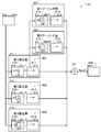
- FIG. 1 is an explanatory diagram showing an image processing system of an embodiment.
- the image processing system 1000 is a system for processing image data of the appearance of the product 700.
- the product 700 may be any product and is predetermined.
- the product 700 is a label sheet on which various objects such as characters and figures are printed.
- the product 700 is also referred to as a label sheet 700.
- the image processing system 1000 includes a data processing device 200 and a digital camera 100 connected to the data processing device 200.
- the data processing device 200 is, for example, a personal computer.
- the data processing device 200 includes a processor 210, a storage device 215, a display unit 240 for displaying an image, an operation unit 250 for accepting an operation by a user, and a communication interface 270. These elements are connected to each other via a bus.
- the storage device 215 includes a volatile storage device 220 and a non-volatile storage device 230.
- the processor 210 is a device that processes data, for example, a CPU.
- the volatile storage device 220 is, for example, a DRAM
- the non-volatile storage device 230 is, for example, a flash memory.
- the non-volatile storage device 230 stores the first program 232, the second program 233, and the prediction model 234.
- the prediction model 234 is a model of an artificial neural network, and is a machine learning model trained by a training process described later (hereinafter, also referred to as “machine learning model 234” or simply “learning model 234”). Call).
- the learning model 234 is a program module. The details of the learning model 234 will be described later.
- the processor 210 stores various intermediate data used for executing the first program 232, the second program 233, and the learning model 234 in the storage device 215 (for example, the volatile storage device 220 and the non-volatile storage device 230). Temporarily store in either).
- the display unit 240 is a device for displaying an image, such as a liquid crystal display or an organic EL display.
- the operation unit 250 is a device that receives operations by the user, such as a touch panel, buttons, and levers that are superposed on the display unit 240. The user can input various instructions to the data processing device 200 by operating the operation unit 250.
- the communication interface 270 is an interface for communicating with other devices (for example, a USB interface, a wired LAN interface, and an IEEE 802.11 wireless interface).
- the digital camera 100 is connected to the communication interface 270.
- FIG. 2 is an explanatory diagram of an example of the learning model 234.
- the function of the learning model 234 is realized by the processor 210 executing the learning model 234 which is a program module.
- Input image data 910 is input to the learning model 234.
- the input image data 910 is image data obtained by optically reading the label sheet 700 (FIG. 1), and the input image 910i represented by the input image data 910 represents the label sheet 700.
- the figure 701 and the character string 702 are printed on the label sheet 700.
- the learning model 234 extracts the features of the input image 910i of the input image data 910 and reconstructs the input image 910i based on the extracted features to generate the output image data 940 representing the output image 940i.
- the output image 940i represents a label sheet 950 reconstructed from the label sheet 700 of the input image 910i.
- the label sheet 950 of the output image 940i has a figure 951 corresponding to the figure 701 and a character string 952 corresponding to the character string 702.
- the input image 910i and the output image 940i are rectangular images having two sides parallel to the first direction D1 and two sides parallel to the second direction D2 perpendicular to the first direction D1. These images 910i and 940i are represented by the color values of the plurality of pixels arranged in a matrix along the first direction D1 and the second direction D2.
- the width W indicates the number of pixels in the first direction D1
- the height H indicates the number of pixels in the second direction D2.
- the input image data 910 and the output image data 940 are bitmap data indicating the color values of the plurality of pixels.
- the color value of each pixel is represented by the gradation value of R (red) G (green) B (blue) of 256 gradations from 0 to 255.
- the actual label sheet 700 may have defects such as a part of an object (figure 701 or character string 702 in this embodiment) being chipped.
- the training model 234 is trained to generate output image data 940 representing a defect-free label sheet, even if the label sheet 700 of the input image 910i has defects (details are detailed. , See below).
- the learning model 234 includes an input layer L10 to which the input image data 910 is input, an intermediate layer L20 for processing the data from the input layer L10, and an output layer L30 for processing the data from the intermediate layer L20. ..
- FIG. 3 is a block diagram showing the configuration of the input layer L10.
- the input layer L10 uses the input image data 910 to generate feature data 920 showing the features of the input image data 910 (that is, the features of the input image 910i).
- Such an input layer L10 is also called an encoder.
- the input layer L10 includes three folding layers 311-313, two pooling layers 321 and 322, and an addition unit 331.
- Input image data 910 is input to each of the three folding layers 311-313.
- the convolution layer 311-313 executes a convolution process and a bias addition process, respectively.
- s first-class input filters FL11 having a size of "p1 ⁇ q1 ⁇ r" are applied to the input data, and the input data and the first
- the value p1 indicates the size (number of pixels) of the first direction D1 of the first-class input filter FL11
- the value q1 indicates the size (number of pixels) of the second direction D2 of the first-class input filter FL11. Indicates the number of color components (3 (RGB) in this embodiment).
- One type 1 input filter FL11 contains "p1 ⁇ q1 ⁇ r" weights.
- the RGB gradation values of "p1 ⁇ q1" pixels of the portion corresponding to the position of the first-class input filter FL11 from the input image data 910, that is, “p1 ⁇ ” A list of "q1 x r" gradation values is acquired. The inner product of the acquired list and the list of "p1 ⁇ q1 ⁇ r" weights of the first-class input filter FL11 is calculated.
- the bias addition process is a process of adding the bias prepared one by one to one type 1 input filter FL11 to the inner product. "Inner product + bias" indicates the correlation value.
- the calculation of the correlation value is performed at each of a plurality of positions of the first-class input filter FL11 while sliding the first-class input filter FL11.
- One type 1 input filter FL11 generates bitmap data 911 indicating a correlation value at each of a plurality of positions of the type 1 input filter FL11.
- the image 911i represented by the bitmap data 911 is also referred to as a feature map or a convolution map.
- the positions of the pixels of the convolution map 911i indicate the positions of the first-class input filter FL11.
- the size of the convolution map 911i that is, the number of pixels in the first direction D1 and the number of pixels in the second direction D2
- the stride the amount by which the filter is slid
- pixels are supplemented by zero padding.
- the total number of filters s is also called the number of channels.
- s bitmap data 911 are generated.
- the number of channels s is 8.
- the convolutional layers 311-313 generate bitmap data 911-913 using the input filters FL11-FL13, respectively.
- the sizes of the three types of input filters FL11 to FL13 are different.
- the type 2 input filter FL12 is larger than the type 1 input filter FL11
- the type 3 input filter FL13 is larger than the type 2 input filter FL12.
- the size comparison between the two filters is done as follows. When the first filter is superposed on the second filter so that the second filter covers the entire first filter, and the second filter includes a portion that does not overlap with the first filter, the second filter is the first filter. Judged to be greater than. The same applies not only to filters but also to comparison of the sizes of two-dimensional areas such as images and windows.
- the size of the first-class input filter FL11 is p1 ⁇ q1
- the size of the second-class input filter FL12 is p2 ⁇ q2
- the size of the third-class input filter FL13 is p3 ⁇ q3.
- the only difference between the convolutional layers 311-313 is the difference in filter size.
- the number of channels s is common to the three convolutional layers 311-313.
- the second convolution layer 312 generates s bitmap data 912 (that is, s convolution maps 912i), and the third convolution layer 313 generates s bitmap data 913 (that is, s sheets).
- the convolution map 913i) is generated. All of the input filters FL11-FL13 are smaller than the input image 910i of the input image data 910. The size of the input filters FL11-FL13 may be set to a larger value as the size of the input image 910i is larger.
- each pixel of the convolution map 911i-913i generated by the convolution layer 311-313 is greatly influenced by the shape of the portion of the object of the input image 910i included in the input filters FL11-FL13.
- the convolution map 911i-913i can show the characteristic of the shape of the portion included in the input filter FL11-FL13.
- the first convolution map 911i may show the shape characteristics of the small size portion included in the small size type 1 input filter FL11.
- the second convolution map 912i may show the shape characteristics of the medium-sized portion contained in the medium-sized second-class input filter FL12.
- the third convolution map 913i may show the shape characteristics of the large-sized portion included in the large-sized third-class input filter FL13.
- the first convolutional layer 311 can extract features of fine shapes such as points
- the second convolutional layer 312 can extract linear features
- the third convolutional layer 313 can extract curved features. ..
- the convolution layer 311-313 can extract the shape characteristics of the portion of the object of the input image 910i included in the input filters FL11-FL13.
- the first convolution map 911i can extract high resolution information.
- the second convolution map 912i can extract information at intermediate resolutions.
- the third convolution map 913i can extract low resolution information. It should be noted that being able to extract features of a fine shape can be rephrased as being able to extract high-resolution information. In addition, being able to extract coarse-shaped features can be rephrased as being able to extract low-resolution information.
- S pieces of bitmap data 911 from the first convolution layer 311 are input to the two pooling layers 321 and 322, respectively.
- the pooling layers 321 and 322 execute a process of determining a representative value using a plurality of values of a plurality of pixels included in the window.
- the pooling layers 321 and 322 perform so-called max pooling, respectively.
- the first pooling layer 321 applies the first window WN21 of "pa ⁇ qa" to the input bitmap data 911.
- the value pa indicates the size (number of pixels) of the first direction D1 of the first window WN21
- the value qa indicates the size (number of pixels) of the second direction D2 of the first window WN21.
- the selection of the maximum value using the first window WN21 is performed at each of the plurality of positions of the first window WN21 while sliding the first window WN21.
- the first pooling layer 321 generates bitmap data 914 indicating the maximum value at each of the plurality of positions of the first window WN21.
- the image 914i represented by the bitmap data 914 is also referred to as a feature map or a pooling map.
- the position of the pixel of the pooling map 914i indicates the position of the first window WN21.
- the size of the output pooling map 914i (that is, the number of pixels in the first direction D1 and the number of pixels in the second direction D2) is the size of the input convolution map 911i (that is, the number of input images 910i). Max pooling is performed so that the size is the same as W ⁇ H). Therefore, the stride (the amount of sliding the window) is 1. Further, around the input convolution map 911i, pixels are supplemented by zero padding.
- S pieces of bitmap data 911 are input to the first pooling layer 321.
- the first pooling layer 321 generates s bitmap data 914 from s bitmap data 911.
- the second pooling layer 322 generates bitmap data 915 using the second window WN22.
- the second window WN22 is larger than the first window WN21.
- the size of the first window WN21 is pa ⁇ qa
- the size of the second window WN22 is pb ⁇ qb.
- the only difference between the pooling layers 321 and 322 is the difference in window size.
- the second pooling layer 322 generates s bitmap data 915 (that is, s pooling maps 915i) from s bitmap data 911 (that is, s convolution maps 911i).
- the convolution map 911i input to the pooling layers 321 and 322 shows the characteristics of the shape of the object of the input image 910i.
- the pooling layers 321 and 322 determine typical values (maximum values in this embodiment) in the windows WN21 and WN22. Therefore, when the displacement of the position of the feature portion in the convolution map 911i is within the range of the windows WN21 and WN22, that is, the displacement of the position of the feature portion of the object in the input image 910i is within the range of the windows WN21 and WN22. If the value is within, approximately the same representative value can be determined from the windows WN21 and WN22.
- the pooling layers 321 and 322 can extract the feature of the shape extracted by the first convolution layer 311 while allowing the displacement of the position of the feature portion within the range of the windows WN21 and WN22.
- the effect of the displacement of the position of the feature portion on the input image 910i on the pooling maps 914i and 915i is mitigated when the displacement of the position is within the range of the windows WN21 and WN22.
- the pooling maps 914i and 915i change according to the displacement of the position.
- the pooling maps 914i and 915i show information regarding the displacement of the position in the input image 910i of the shape feature extracted by the first convolution layer 311.
- the addition unit 331 generates feature data 920 using five bitmap data 911-915 from the convolution layer 311-313 and the pooling layers 321 and 322.
- the feature data 920 represents a map of the same size as the input map 911i-915i (also referred to as a feature map 920i).
- the addition unit 331 inputs the total value of the five values of the five pixels of the five pixels at the same position of the five maps 911i-915i into the activation function, and inputs the calculated value of the activation function to the feature map. It is adopted as the value of the pixel at the same position of the 920i.
- a so-called ReLU Rectified Linear Unit
- the addition unit 331 executes a process of generating one feature data 920 from the five bitmap data 911-915 for each channel. In this embodiment, since the number of channels s is 8, the addition unit 331 generates eight feature data 920s.
- the s feature data 920 are supplied to the intermediate layer L20 (FIG. 2).
- the first convolution layer 311 has s weights of "p1 x q1 x r x s" of the first type input filter FL11 and s biases corresponding to s first type input filters FL11. And the arithmetic parameter set 601 including.
- the second convolution layer 312 utilizes an arithmetic parameter set 602 that includes "p1 x q1 x r x s" weights and s biases of s second-class input filters FL12.
- the third convolution layer 313 utilizes an arithmetic parameter set 603 including "p1 ⁇ q1 ⁇ r ⁇ s" weights and s biases of s third-class output filters FL33.
- FIG. 4 is a block diagram showing the configuration of the intermediate layer L20.
- the intermediate layer L20 uses s feature data 920 to generate s intermediate data 930 for output.
- the intermediate layer L20 includes a first conversion unit 410, a first fully connected layer 415, a second fully connected layer 420, and a second conversion unit 430.
- One feature map 920i shows each value of "W ⁇ H” pixels (hereinafter, the value associated with the pixel of the feature map is also referred to as a feature value).
- the s feature data 920 shows "W ⁇ H ⁇ s" feature values.
- the first fully connected layer 415 which will be described later, processes "W ⁇ H ⁇ s" of feature values as a one-dimensional vector.
- the first conversion unit 410 sets the reference order of the "W ⁇ H ⁇ s" feature values according to the predetermined correspondence between the “W ⁇ H ⁇ s” feature values and the elements of the one-dimensional vector. Convert in the reference order of the elements of the one-dimensional vector.
- the first conversion unit 410 may be omitted, and the first fully connected layer 415 may refer to "W ⁇ H ⁇ s" of feature values according to the above correspondence.
- the first fully connected layer 415 is a layer similar to the fully connected layer used in a general neural network.
- the first fully connected layer 415 calculates N feature values using "W ⁇ H ⁇ s" feature values.
- N may be an integer of 1 or more and may be an integer of 2 or more.
- N may be the same as “W ⁇ H ⁇ s” and may be an integer smaller than “W ⁇ H ⁇ s”. Further, N may be an integer larger than "W ⁇ H ⁇ s”.
- Each of the N feature values is also called a latent variable (hereinafter, also referred to as a latent variable 920z).
- the first fully connected layer 415 calculates the inner product of the input vector composed of "W ⁇ H ⁇ s" feature values and the weight vector composed of "W ⁇ H ⁇ s" weights. ..
- the calculated inner product is output as one feature value. Bias addition and operation by the activation function are omitted.
- the weight vector is prepared separately for each of the N intermediate values.
- the first fully connected layer 415 utilizes an arithmetic parameter set 608 containing N weight vectors (ie, "W ⁇ H ⁇ s ⁇ N" weights).
- the second fully connected layer 420 is a layer similar to the fully connected layer used in a general neural network.
- the second fully connected layer 420 calculates "W ⁇ H ⁇ s" intermediate values using N feature values from the first fully connected layer 415.
- the second fully connected layer 420 calculates a value (inner product + bias) obtained by adding a bias to the inner product of the input vector composed of N feature values and the weight vector composed of N weights. , Enter the calculated value into the activation function.
- the calculated value of the activation function is used as one intermediate value. In this embodiment, so-called ReLU is used as the activation function.
- the weight vector and the bias are prepared separately for each of the "W ⁇ H ⁇ s" intermediate values.
- the second fully connected layer 420 includes "WxHxs" weight vectors (ie, "NxWxHxs" weights) and "WxHxs" biases.
- the arithmetic parameter set 604 is used.
- the output layer L30 processes "W ⁇ H ⁇ s" intermediate values as s maps.
- One map is represented by the values of "WxH” pixels, similar to an image of "WxH” size.
- the second conversion unit 430 refers to the "W ⁇ H ⁇ s" intermediate values according to a predetermined correspondence between the "W ⁇ H ⁇ s" intermediate values and the plurality of pixels of the s map. The order is converted to the reference order of a plurality of pixels of the s map.
- each of the s maps is also referred to as an intermediate map 930i. Further, the data showing the intermediate map 930i is also referred to as intermediate data 930.
- the intermediate layer L20 generates s intermediate data 930.
- the s intermediate data 930 are supplied to the output layer L30 (FIG. 2).
- the intermediate value of the intermediate map 930i is calculated using N feature values of the latent variable 920z. Therefore, the intermediate value indicates the characteristics of the object of the input image 910i.
- the second conversion unit 430 is omitted, and the output layer L30 may refer to "W ⁇ H ⁇ s" intermediate values according to the above correspondence.
- FIG. 5 is a block diagram showing the configuration of the output layer L30.
- the output layer L30 uses s intermediate data 930 to generate output image data 940 indicating an image of the object.
- Such an output layer L30 is also called a decoder.
- the output layer L30 includes three transposed folding layers 511, 512, 513, and an addition unit 520.
- the transposed convolution layer 511-513 respectively, executes transposed convolution and bias addition processing.
- the transpose convolution is a process of restoring the features extracted by the convolution process, and includes, for example, a process of enlarging the input map and a convolution process of using the enlarged map. Such transpose convolution is used as part of the decoder. In this embodiment, the map enlargement process is omitted. Then, the transposed convolution layer 511-513 generates one image from the s intermediate maps 930i by the convolution process.
- the input data is applied by applying the first-class output filter FL31 having a size of "p1 ⁇ q1 ⁇ s" to the input s intermediate data 930.
- This is a process of calculating a correlation value indicating a correlation between the first type output filter FL31 and the first type output filter FL31.
- the values p1 and q1 are the sizes of the first-class output filter FL31, and are the same as the size of the first-class input filter FL11 of the first convolution layer 311 (FIG. 3).
- the first transposed convolution layer 511 utilizes r first-class output filters FL31.
- One type 1 output filter FL31 contains "p1 ⁇ q1 ⁇ s" weights.
- the intermediate value of "p1 ⁇ q1" pixels of the portion corresponding to the position of the first-class output filter FL31 from each of the s intermediate data 930, that is, "p1" A list of "xq1 x s" intermediate values is obtained.
- the inner product of the acquired list and the list of "p1 ⁇ q1 ⁇ s" weights of the first-class output filter FL31 is calculated.
- the bias addition process is a process of adding the bias prepared one by one to one type 1 output filter FL31 to the inner product. "Inner product + bias" indicates the correlation value.
- the calculation of the correlation value is performed at each of a plurality of positions of the first-class output filter FL31 while sliding the first-class output filter FL31.
- One type 1 output filter FL31 generates bitmap data 931 indicating a correlation value at each of a plurality of positions of the type 1 output filter FL31.
- the correlation value a value that restores the feature indicated by the intermediate value of the plurality of pixels corresponding to the first-class output filter FL31 is calculated.
- the image 931i represented by the bitmap data 931 is also referred to as a partially restored image.
- the position of the pixel of the partially restored image 931i indicates the position of the first-class output filter FL31.
- the size of the partially restored image 931i (that is, the number of pixels in the first direction D1 and the number of pixels in the second direction D2) is the same as the size of the intermediate map 930i (that is, W ⁇ H).
- the convolution process is performed. Therefore, the stride (the amount by which the filter is slid) is 1. Also, around the intermediate map 930i, the pixels are supplemented by zero padding.
- one pixel of the partially restored image 931i is associated with the gradation values of r color components in the same manner as the pixel of the input image 910i.
- the value r is 3, and one pixel is associated with three RGB gradation values.
- the first transposed convolution layer 511 calculates r values for each pixel by using r first-class output filters FL31.
- the bitmap data 931 generated by the first transposed convolution layer 511 is r-color bitmap data.
- the transposed convolution layers 511-513 generate bitmap data 931-933, respectively, using the output filters FL31-FL33.
- the sizes of the three types of output filters FL31 and FL33 are different.
- the size of the type 2 output filter FL32 is the same as the size of the type 2 input filter FL12 (p2 ⁇ q2), and the size of the type 3 output filter FL33 is the size of the type 3 input filter FL13 (p3 ⁇ q3). ) Is the same.
- the only difference between the transposed convolution layers 511-513 is the difference in filter size.
- the second translocation convolution layer 512 generates one r-color bitmap data 932 (that is, one r-color partially restored image 932i), and the third translocation convolution layer 513 generates one r-color bitmap data 932i.
- Color bitmap data 933 (that is, one r-color partially restored image 933i) is generated. All of the output filters FL31-FL33 are smaller than the output image 940i of the output image data 940.
- the value of each pixel of the partially restored images 931i-933i generated by the transposed convolution layer 511-513 is greatly influenced by the intermediate value of the portion included in the output filter FL31-FL33 in the intermediate map 930i.
- the intermediate value of the intermediate map 930i indicates the characteristics (including the shape characteristics) of the object of the input image 910i. Therefore, the partially restored images 931i-931i may exhibit the shape features indicated by the portions corresponding to the output filters FL31-FL33.
- the first partially restored image 931i may exhibit the features of the small size shape indicated by the portion corresponding to the small size type 1 output filter FL31.
- the second partially restored image 932i may exhibit the characteristics of the medium size shape indicated by the portion corresponding to the medium size type 2 output filter FL32.
- the third partially restored image 933i may show the features of the large size shape indicated by the portion corresponding to the large size type 3 output filter FL33.
- the first transposed convolution layer 511 can restore fine shape features such as points
- the second transpose convolution layer 512 can restore linear features
- the third transpose convolution layer 513 can restore curvilinear features. Can be restored.
- the transposed convolution layer 511-513 can restore the shape characteristics by using the portion of the intermediate data 930 corresponding to the output filters FL31-FL33.
- the first partially restored image 931i can restore high resolution information.
- the second partially restored image 932i can restore information at an intermediate resolution.
- the third partially restored image 933i can restore low resolution information. It should be noted that being able to restore the features of a fine shape can be rephrased as being able to restore high resolution information. In addition, being able to restore coarse-shaped features can be rephrased as being able to restore low-resolution information.
- the addition unit 520 generates output image data 940 using the three bitmap data 931-933 from the transposed convolution layer 511-513.
- the output image data 940 represents an output image 940i having the same size as the input partially restored image 931i-932i.
- the addition unit 520 inputs the total value of the three values of the three pixels of the three pixels at the same position of the three partially restored images 931i-933i into the activation function, and inputs the calculated value of the activation function to the activation function. It is adopted as the value of the pixel at the same position of the output image 940i.
- a so-called sigmoid function is used as the activation function.
- the addition unit 520 calculates the pixel value for each of r color components.
- the gradation value of the red R of the pixel at the same position of the output image 940i is used by using the gradation value of the three red R of the three pixels of the same position of the three partially restored images 931i-933i. The value is calculated. The gradation value of green G and the gradation value of blue B are also calculated in the same manner.
- the output image 940i generated may show the restored features of various sizes of shapes, i.e., label sheets.
- the first transposed convolution layer 511 has r weights of "p1 x q1 x s x r" of r first-class output filters FL31 and r corresponding to r first-class output filters FL31. Utilizes a bias and an arithmetic parameter set 605 that includes.
- the second transposed convolution layer 512 utilizes an arithmetic parameter set 606 containing "p1 ⁇ q1 ⁇ s ⁇ r" weights and r biases of r second-class output filters FL32.
- the third transposed convolution layer 513 utilizes an arithmetic parameter set 607 that includes "p1 x q1 x s x r" weights and r biases of r third-class output filters FL33.
- FIG. 6 is a flowchart showing an example of training processing for generating the learning model 234.
- the learning model 234 is trained so that when the image data of the label sheet 700 is input, the image data of the label sheet without defects is generated.
- a plurality of arithmetic parameters including the above arithmetic parameter set 601-608 (FIGS. 3-FIG. 5) are adjusted.
- the training is performed by the data processing device 200 (FIG. 1).
- the processor 210 executes the training process according to the first program 232.
- the processor 210 initializes a plurality of arithmetic parameters (including arithmetic parameter sets 601-608) of the learning model 234. For example, each arithmetic parameter is set to a random value.
- the processor 210 acquires the reference image data.
- the reference image data is image data of a label sheet without defects (also referred to as a reference label sheet).
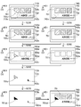
- FIG. 7A is an explanatory diagram of the reference label sheet 800.
- a figure 801 and a character string 802 are printed on the reference label sheet 800.
- FIG. 7B is an explanatory diagram of an example of reference image data.
- the reference image data 810 is image data obtained by photographing the reference label sheet 800.
- the operator arranges the reference label sheet 800 in the photographing area of the digital camera 100 (FIG. 1).
- the processor 210 supplies a shooting instruction to the digital camera 100.
- the digital camera 100 photographs the reference label sheet 800 and generates reference image data in response to the instruction.
- the processor 210 acquires the reference image data from the digital camera 100 and stores the reference image data in the non-volatile storage device 230.
- the processor 210 may acquire the reference image data 810 by executing a crop process for cutting out a portion of the image data acquired from the digital camera 100 indicating the reference label sheet 800.
- the processor 210 generates a plurality of training input image data using the reference image data 810, and stores the generated plurality of training input image data in the non-volatile storage device 230.
- the plurality of learning input image data are generated by changing the position or orientation of the reference label sheet 800 in the reference image 810i.
- one or more of the four parameters of the movement direction, the movement amount, the rotation direction, and the rotation angle are different from each other. These parameters are changed within the amount of deviation that can occur when the image data of the label sheet is acquired by optically reading the label sheet.
- the process of generating a plurality of image data for learning by processing the existing image data is also called "data augmentation".
- the color may be changed, noise may be added, and smoothing may be performed, not limited to the change of position or orientation.
- the plurality of learning input image data represents the defect-free reference label sheet 800.
- the processor 210 selects V training input image data (V is an integer of 1 or more) from a plurality of training input image data, inputs V training input image data to the training model 234, and V Output image data of is generated.
- V learning input image data unused learning input image data among the plurality of learning input image data may be selected. Further, V learning input image data may be randomly selected from a plurality of learning input image data.
- the processor 210 has an error indicating a difference between the training input image data and the output image data corresponding to the training input image data for each of the V training input image data input to the training model 234. Calculate the value.
- the error value is calculated based on a predetermined loss function. For example, a mean squared error (MSE (Mean Squared Error)) is used to calculate the error value. The error value becomes smaller as the difference between the learning input image data and the output image data becomes smaller.
- MSE Mel Squared Error
- the processor 210 adjusts a plurality of arithmetic parameters (including the arithmetic parameter set 601-608) of the learning model 234 using V error values. Specifically, the processor 210 adjusts a plurality of arithmetic parameters according to a predetermined algorithm so that the error value becomes small, that is, the difference between the training input image data and the output image data becomes small. ..
- the algorithm for example, an algorithm using an error backpropagation method and a gradient descent method is used.
- the processor 210 determines whether or not the training has been completed.
- the condition for completing the training may be, for example, that all the error values calculated in S135 are smaller than the predetermined error thresholds. Instead, the condition for completing the training may be that a completion instruction from the worker has been input.
- the operator confirms whether or not the image represented by the output image data can sufficiently reproduce the image represented by the corresponding learning input image data.
- the operator inputs a training completion instruction or a continuation instruction via the operation unit 250 according to the confirmation result.
- the condition for completing the training may be that the number of times the processing of S130-S140 is executed is equal to or greater than a predetermined number of times threshold value.
- the processor 210 shifts to S130.
- the learning model 234 having the adjusted arithmetic parameters that is, the trained learning model 234.
- the trained learning model 234 is configured to make the computer function to perform processing using the adjusted parameters. As described in FIG. 2-FIG. 5, the training model 234 extracts features (including shape features) of the input image object (here, the figure and character string of the label sheet). Restore an image of an object based on its features.
- FIG. 7C is an explanatory diagram of an example of output image data generated by the trained learning model 234.
- the output image data 840 shows an example of image data generated by inputting the image data 810 of FIG. 7B into the trained learning model 234.
- the output image 840i of the output image data 840 represents a label sheet 800 (including the graphic 801 and the character string 802) which is almost the same as the reference label sheet 800 of the image 810i of FIG. 7 (B).
- the training model 234 is trained using the training input image data of the defect-free object. In this case, the trained learning model 234 generates output image data representing the defect-free object regardless of whether the input image object has a defect or not.
- FIG. 8 is a flowchart showing an example of the difference data generation process. Difference data can be used to determine if the label sheet sample is defective.
- the generation of the difference data is executed by the data processing device 200 (FIG. 1).
- the processor 210 executes the difference data generation process according to the second program 233.
- the processor 210 acquires the target input image data which is the image data of the sample of the label sheet, and stores the acquired target input image data in the storage device 215 (for example, the non-volatile storage device 230).
- the acquisition of the target input image data 710 is performed using the digital camera 100 in the same manner as in the process of S115 of FIG.
- FIG. 9 is an explanatory diagram of image processing.
- examples of a plurality of images 710i, 740i, 710bi, 740bi, 760di, 740ei, 770i, 770bi, and 780i processed by the difference data generation process are shown. These images are arranged in the order of processing from top to bottom in the figure.
- the target input image 710i of the target input image data 710 is shown in the upper left of FIG. 9.
- the target input image 710i represents a defective label sheet 700x (also referred to as an input label sheet 700x).
- the label sheet 700x has a partially chipped 701x of the figure 701 and a partially chipped 702x of the character string 702.
- the target input image 710i contains noise 710n. Noise 710n can be generated by various causes such as data processing in the digital camera 100.
- the processor 210 In S220 (FIG. 8), the processor 210 generates the target output image data by inputting the target input image data into the trained learning model 234.
- the target output image 740i of the target output image data 740 is shown in the upper right of FIG. 9.
- the target output image 740i represents a defect-free label sheet 750 (also referred to as an output label sheet 750).
- the position and orientation of the output label sheet 750 in the target output image 740i is approximately the same as the position and orientation of the input label sheet 700x in the target input image 710i.
- the figure 751 and the character string 752 of the output label sheet 750 are substantially the same as the figure 801 and the character string 802 of the reference label sheet 800 (FIG. 7 (A)).
- the target output image 740i contains noise 740n.
- the noise 740n can be generated by various causes such as calculation by the learning model 234.
- the processor 210 performs a smoothing process on the target input image data and the target output image data to generate the smoothed input image data and the smoothed output image data (the smoothing process is also a blurring process). be called).
- the smoothing process is a process using an average value filter.
- the smoothing filter may be various other filters such as a median filter and a Gaussian filter.
- the smoothing process is not limited to the process using the smoothing filter, and may be various processes for slowing the change of the color value (also referred to as the pixel value) of the pixel with respect to the change of the position on the image.
- the processor 210 performs edge extraction processing on the smooth output image data to generate edge image data.
- the processor 210 calculates the luminance value from the pixel value (RGB value), applies a known Sobel filter to the luminance value, and calculates the edge amount of each pixel. Then, the processor 210 extracts pixels having an edge amount larger than a predetermined threshold value as edge pixels.
- the edge image 740ei of the edge image data 740e is shown on the right side of the third row from the top of FIG.
- the edge image 740ei includes an edge portion 750e of the output label sheet 750 (for example, a contour), an edge portion 751e of the figure 751 (for example, a contour or a pattern of a figure), and an edge portion 752e of the character string 752 (for example, a contour).
- the edge image data 740e is binary bitmap data. A pixel value of zero indicates an edge pixel, and a pixel value of 1 indicates a non-edge pixel.
- the edge extraction filter may be various other filters such as a Prewitt filter and a Roberts filter. Further, the edge extraction process is not limited to the process using the edge extraction filter, and may be various processes for extracting pixels in a portion where the pixel value changes rapidly with respect to the change in the position on the image.
- the processor 210 In S250 (FIG. 8), the processor 210 generates differential image data indicating the difference between the smooth input image data and the smooth output image data.
- the difference image data represents a difference image showing the difference between the smooth input image 710bi and the smooth output image 740bi.
- the processor 210 adopts the difference between the two color values of the two pixels at the same position of the smooth input image 710b and the smooth output image 740bi as the color value of the pixels at the same position of the difference image.
- the pixel value of the difference image is the absolute difference between the brightness value calculated from the RGB pixel value of the smooth input image data and the brightness value calculated from the RGB pixel value of the smooth output image data. Set to a value.
- a zero pixel value in the difference image indicates that the difference between the two image data is zero.
- the larger the pixel value of the difference image the larger the difference between the two image data.
- the difference image 760di of the difference image data 760d is shown.
- the smooth input image 710bi has a missing 701x of the figure 701 and a missing 702x of the character string 702.
- the smooth output image 740bi does not have such a chip. Therefore, the difference image 760di shows the chipped portion 701z corresponding to the chipped portion 701x of the figure 701 and the chipped portion 702z corresponding to the chipped portion 702x of the character string 702.
- the difference image 760di can represent the edge portion 700d of the label sheet, the edge portion 701d of the figure, and the edge portion 702d of the character string.
- the pixel value of the difference image may be represented by another color component.
- the pixel value of the difference image may indicate the gradation values of three colors, that is, the absolute value of the difference of red R, the absolute value of the difference of green G, and the absolute value of the difference of blue B.
- the processor 210 corrects the difference image data 760d using the edge image data 740e. Specifically, a process of extracting a non-edge portion different from the edge portion from the difference image 760di is executed.
- the processor 210 refers to the edge image data 740e and generates the corrected difference image data by setting the pixel value of the edge portion of the difference image data 760d to zero.
- the corrected difference image 770i of the corrected difference image data 770 is shown on the left side of the fourth row from the top of FIG.
- the corrected difference image 770i shows the missing portions 701z and 702z.
- the edge portions 700d, 701d, and 702d included in the difference image 760di have been deleted.
- a zero pixel value of the edge image data 740e indicates an edge pixel
- a pixel value of 1 indicates a non-edge pixel. Therefore, the processor 210 can generate the corrected difference image data 770 by multiplying the pixel value of the pixel of the difference image data 760d by the pixel value of the pixel at the same position of the edge image data 740e.
- the processor 210 binarizes the corrected difference image data 770 to generate binary difference image data.
- the processor 210 performs binarization by comparing the pixel value of the corrected differential image data 770 with a predetermined binarization threshold.
- the binary difference image 770bi of the binary difference image data 770b is shown.
- the binary difference image 770bi shows the difference portions 701zb and 702zb corresponding to the missing portions 701z and 702z of the corrected difference image data 770.
- the binarization method may be various methods for discriminating between a large value and a small value. For example, the so-called binarization of Otsu may be adopted.
- the processor 210 synthesizes the target output image data 740 and the binary difference image data 770b to generate the composite image data.
- the processor 210 generates composite image data by changing the color of the difference portion of the target output image to a predetermined specific color (for example, white, red, etc.).
- the composite image 780i of the composite image data 780 is shown on the right side at the bottom of FIG. 9. Differences 701zb and 702zb of the output label sheet 750 are shown in specific colors.
- the processor 210 stores image data indicating a difference portion between the target input image and the target output image in the storage device 215 (for example, the non-volatile storage device 230).
- the difference image data (S250), the corrected difference image data (S260), the binary difference image data (S270), and the composite image data (S280) show a difference portion. All of these four image data are image data obtained by using the difference image data (S250).
- the image data stored in the storage device in S290 may be one or more image data arbitrarily selected from the above four image data.
- the processor 210 stores the binary difference image data and the composite image data in the non-volatile storage device 230.
- the image data stored in the storage device in S290 can be used in various processes.
- the processor 210 may display the composite image 780i (FIG. 9) on the display unit 240.
- the observer of the composite image 780i can easily identify the difference portions 701 zb and 702 zb (particularly the position and shape).
- the processor 210 may determine whether or not the input label sheet 700x has a defect by analyzing the binary difference image data 770b. For example, when the size of one continuous difference portion (for example, the number of pixels) is equal to or larger than a predetermined threshold value, it may be determined that the input label sheet has a defect.
- the learning model 234 of FIG. 2 is a machine learning model that generates output image data 940 corresponding to the input image data 910 of the input image 910i including the label sheet 700. Then, in the process of FIG. 8, the trained learning model 234 is used. As described with reference to FIGS. 2 to 5, the learning model 234 is a model that executes an operation using a plurality of arithmetic parameters (including an arithmetic parameter set 601-608) for the input image data 910. As described with reference to FIG. 3, the shape of the input object (in this embodiment, the figure 701 and the character string 702 of the label sheet 700) included in the input image 910i of the input image data 910 is formed by the calculation based on the learning model 234.
- the learning model 234 includes an input layer L10 that executes an operation using the input image data 910 and an output layer L30 that is provided on the downstream side of the input layer L10 and generates the output image data 940. I have.
- the input layer L10 includes a folding layer 311-313, a pooling layer 321 and 322, and an addition unit 331.
- the first convolution layer 311 is a feature of the shape of a portion of an input object (figure 701, character string 702, etc.) that is an object of the input image 910i and is included in the range of the first-class input filter FL11 smaller than the input image 910i. This is an example of the first extraction unit for extracting.
- the second folding layer 312 is provided in parallel with the first folding layer 311.
- the second convolution layer 312 extracts the shape characteristics of the portion of the input object included in the range of the second-class input filter FL12, which is smaller than the input image 910i and larger than the range of the first-class input filter FL11. This is an example of the extraction unit.
- the pooling layers 321 and 322 generate bitmap data 914 and 915 of the pooling maps 914i and 915i by executing an operation using the data output from the first convolution layer 311.
- the pooling maps 914i, 915i can be affected by the displacement of positions within the input image 910i of the shape features extracted by the first convolutional layer 311. If the displacement of the position is within the range of windows WN21 and WN22, the effect is mitigated. If the displacement of the position exceeds the range of windows WN21, WN22, the pooling maps 914i, 915i may change according to the displacement of the position.
- the pooling maps 914i and 915i are examples of displacement information regarding the displacement of the position.
- the pooling layers 321 and 322 are examples of displacement information acquisition units that acquire displacement information.
- the addition unit 331 adds a plurality of data including data output from the first convolution layer 311, data output from the second convolution layer 312, and data output from the pooling layers 321 and 322. To do.
- the first convolution layer 311 outputs data corresponding to features having a relatively fine shape
- the second convolution layer 312 outputs data corresponding to features having a relatively coarse shape.
- the first convolutional layer 311 can extract features of fine shape
- the second convolutional layer 312 can extract features of lines.
- the addition unit 331 of the input layer L10 adds those data. Therefore, the learning model 234 can generate output image data 940 representing an output object having a relatively fine shape in addition to a relatively coarse shape.
- a plurality of convolution layers using filters of different sizes are not provided in parallel, but a plurality of processing layers (for example, a plurality of convolution layers) are connected in series. In this case, features with a relatively coarse shape can be extracted, but it is difficult to extract features with a relatively fine shape. According to the above configuration, such a defect can be suppressed.
- the target of addition by the addition unit 331 includes data output from the pooling layers 321 and 322.
- the pooling layers 321 and 322 generate bitmap data 914 and 915 using the data corresponding to the relatively fine shape features from the first convolution layer 311.
- the influence of the displacement of the positions within the range of the windows WN21 and WN22 is mitigated. Therefore, robustness can be improved against displacement of the position in the input image of the feature having a relatively fine shape.
- the output layer L30 includes a transposed convolution layer 511-513 and an addition unit 520.
- the first transposed convolution layer 511 is a first restoration unit that restores shape features by using a portion of the intermediate data 930 to be processed that corresponds to the range of the first-class output filter FL31 that is smaller than the output image 940i.
- the second transposed folding layer 512 is provided in parallel with the first transposed folding layer 511.
- the second transposed convolution layer 512 uses a portion of the intermediate data 930 to be processed that corresponds to the range of the second class output filter FL32, which is smaller than the output image 940i and larger than the range of the first class output filter FL31. This is an example of a second restoration unit that restores the characteristics of the shape.
- the first transposed folding layer 511 restores the features of a relatively fine shape
- the second transposed folding layer 512 restores the features of a relatively coarse shape. Therefore, the learning model 234 can generate output image data 940 representing an output object having a relatively fine shape in addition to a relatively coarse shape.
- the input layer L10 includes a first convolutional layer 311 which is an example of the first extraction unit, a second convolutional layer 312 which is an example of the second extraction unit, and an example of the displacement information acquisition unit.
- the pooling layers 321 and 322 are included.
- the output layer L30 does not include the pooling layer, but includes the first transposed convolution layer 511 which is an example of the first restoration unit and the second transpose convolution layer 512 which is an example of the second restoration unit. I'm out. Since the input layer L10 includes the pooling layers 321 and 322, the influence of the displacement of the position of the shape feature in the input image 910i on the calculation by the output layer L30 is mitigated. Therefore, the output layer L30 including the first transposed convolution layer 511 and the second transposed convolution layer 512 without including the pooling layer is an output image representing an output object having a relatively fine shape in addition to a relatively coarse shape. Data 940 can be generated.
- the input layer L10 includes a first pooling layer 321 and a second pooling layer 322.
- the first pooling layer 321 is an example of a first displacement information acquisition unit that acquires bitmap data 914 regarding the displacement of the position within the range of the first window WN21, which is smaller than the input image 910i.
- the second pooling layer 322 is provided in parallel with the first pooling layer 321.
- the second pooling layer 322 is an example of a second displacement information acquisition unit that acquires bitmap data 915 regarding the displacement of the position within the range of the second window WN22, which is smaller than the input image 910i and larger than the range of the first window WN21. Is.
- the addition unit 331 adds a plurality of data including data output from each of the first convolution layer 311 and the second convolution layer 312, the first pooling layer 321 and the second pooling layer 322.
- the first pooling layer 321 acquires the first bitmap data 914 regarding the displacement at a relatively small position
- the second pooling layer 322 acquires the second bitmap data 915 regarding the displacement at a relatively large position.
- the addition unit 331 of the input layer L10 adds the data, the robustness can be improved with respect to the displacement at a relatively small position and the displacement at a relatively large position.
- the input layer L10 (FIG. 3) includes a third folding layer 313 provided in parallel with the first folding layer 311 and the second folding layer 312.
- the third convolution layer 313 extracts the shape characteristics of the portion of the input object included in the range of the third type input filter FL13, which is smaller than the input image 910i and larger than the range of the second type input filter FL12.
- the addition unit 331 includes a plurality of data including data output from each of the first convolution layer 311, the second convolution layer 312, the third convolution layer 313, the first pooling layer 321 and the second pooling layer 322. Add the data of.
- Output image data 940 representing an output object having shape features can be generated.
- the plurality of arithmetic parameters (including the arithmetic parameter set 601-608) of the learning model 234 are obtained by training the learning input image data and the learning input image data in the learning model 234. It is adjusted so that the difference between the output image data generated by inputting to is small.
- the learning input image data is generated by using the reference image data 810 of the reference image 810i including the reference label sheet 800.
- Each of the plurality of learning input image data is the image data of the reference image including the reference label sheet 800. Therefore, as described with reference to FIGS.
- the output label has a small difference from the reference label sheet 800.
- the target output image data 740 of the target output image 740i including the sheet 750 can be generated.
- Such target output image data 740 can be used for detecting defects in the object (here, input label sheet 700x) of the target input image 710i.
- the processor 210 performs the following processes using the trained learning model 234.
- the processor 210 acquires the target input image data 710 of the target input image 710i including the input object.
- the processor 210 inputs the target input image data 710 into the trained learning model 234 to generate the target output image data 740 corresponding to the target input image data 710.
- the processor 210 generates the difference image data 760d of the difference image 760di showing the difference between the target input image 710i and the target output image 740i.
- the learning model 234 uses the target output image data 740 of the target output image 740i including the output label sheet 750, which is an output label sheet 750 based on the characteristics of the shape extracted by the input layer L10 and has a small difference from the reference label sheet 800. Can be generated. Therefore, the processor 210 can generate the difference image data 760d indicating the difference between the input label sheet 700x and the reference label sheet 800.
- the processor 210 smoothes the target input image data 710 and the target output image data 740 to smooth the smooth input image data 710b and the smooth output image data 740b. And the smooth input image data 710b and the smooth output image data 740b are used to generate the difference image data 760d. Therefore, the noise included in the difference image data 760d can be reduced.
- the processor 210 performs an edge extraction process for extracting an edge portion in the smooth output image 740bi of the smooth output image data 740b (S240), and performs an edge extraction process from the difference image 760di.
- the difference image data is corrected by performing the process of extracting the non-edge portion different from the portion on the difference image data 760d (S260). Due to the misalignment of the objects between the target input image 710i and the target output image 740i, the difference image 760di may include edges. According to the above configuration, the corrected difference image data 770 can appropriately show a difference different from the edge due to the misalignment between the target input image 710i and the target output image 740i.
- the input layer of the learning model is not limited to the convolutional layer 311-313 (FIG. 3), and includes various arithmetic units (also called extraction units) for extracting the shape features of the input object included in the input image. It's okay.
- the extraction unit uses the pixel values of one or more pixels of the portion included in the input range smaller than the input image of the input image to characterize the shape of the portion included in the input range of the input object. It may be configured to extract.
- the input layer preferably includes a plurality of extraction units using input ranges of different sizes. This allows the input layers to extract features of shapes of different sizes. In other words, the input layer can extract information with different resolutions from each other.
- the total number of extraction units may be any number of 2 or more.
- the amount of calculation of the learning model increases as the size (number of pixels) of the input image increases, and increases as the total number of extraction units increases. Therefore, when the size of the input image is large, it is preferable that the total number of extraction units is small.
- the pooling layers 321 and 322 included in the input layer L10 of the learning model 234 are not limited to the max pooling process, and perform various processes for determining representative values using one or more pixels in the windows WN21 and WN22. You can do it.
- the pooling layers 321 and 322 may perform an average pooling process.
- the bitmap data 912 from the second convolution layer 312 may be input to the pooling layers 321 and 322.
- the bitmap data 912 shows a feature of a finer shape as compared with the bitmap data 913 from the third convolution layer 313. Therefore, robustness can be improved with respect to displacement of the position in the input image of the feature having a relatively fine shape.
- the data generated by the pooling layers 321 and 322 is an example of displacement information regarding the displacement of the position in the input image of the shape features extracted by the extraction unit (eg, convolutional layer 311-313).
- the displacement information may be various information that changes according to the displacement of the position.
- the displacement information has a small effect of the displacement of the position on the displacement information when the displacement of the position of the object on the input image is within the predetermined displacement range, and when the displacement of the position exceeds the displacement range, the displacement information has a small effect. It may be determined so that the influence of the displacement of the position on the displacement information is large.
- the input layer is not limited to the pooling layer, and may include various arithmetic units (referred to as displacement information acquisition units) for acquiring displacement information.
- the input layer preferably includes a plurality of displacement information acquisition units that use displacement ranges of different sizes. This makes it possible to improve robustness against displacements of different sizes.
- the total number of displacement information acquisition units may be any number of 1 or more. When the size of the input image is large, it is preferable that the total number of displacement information acquisition units is small. In any case, it is preferable that the addition unit of the input layer adds data from each of the plurality of extraction units and one or more displacement information acquisition units. This allows the input layer to extract shape features of parts of various sizes and improve robustness to misalignment of objects in the input image. Further, one or more displacement information acquisition units may acquire displacement information using the same data from the same extraction unit.
- a plurality of extraction units of the input layer include a first extraction unit that uses the first input range and a second extraction unit that uses a second input range that is larger than the first input range, one or more. It is preferable that the displacement information acquisition unit uses the data from the first extraction unit. This makes it possible to improve robustness against displacement of the position of features with relatively fine shapes.
- the input layer does not have to include a displacement information acquisition unit that uses data from the second extraction unit. As a result, the configuration of the input layer can be simplified.
- the output layer of the learning model is not limited to the transposed convolution layer 511-513 (FIG. 5), and may include various arithmetic units (also referred to as restoration units) that restore the characteristics of the shape.
- the restoration unit may process the processing target data indicating the characteristics of the object (including the characteristics of the shape) as image data. Then, the restoration unit is configured to restore the characteristics of the shape by using the pixel values of one or more pixels of the portion of the image indicated by the processing target data that is included in the output range smaller than the output image. It's okay.
- the output layer preferably includes a plurality of restoration units using output ranges of different sizes. This allows the output layers to restore features of shapes of different sizes. In other words, the output layers can restore information with different resolutions from each other.
- the output layer includes an addition unit that adds data output from each of the plurality of restoration units. Then, the data output from the addition unit may be used as the output image data. Thereby, features of shapes having different sizes can be appropriately restored.
- the output layer does not have to include a pooling layer (and thus a displacement information acquisition unit).
- the total number of restoration units may be any number of 1 or more, and is preferably 2 or more. When the size of the input image is large, it is preferable that the total number of restoration units is small.
- the size of the output range of the restoration unit of the output layer may be different from the size of the input range of the extraction unit of the input layer.
- the total number of restoration units in the output layer may differ from the total number of extraction units in the input layer.
- the input layer is provided with U (U is an integer of 2 or more) extraction units using input ranges of different sizes
- the output layer is provided with U restoration units using output ranges of different sizes. It is preferable that the size of the U input ranges is the same as the size of the U output ranges. As a result, it is possible to appropriately extract and restore features of a plurality of types of shapes having a plurality of sizes different from each other.
- the fully connected layers 415 and 420 are from the addition unit 331 of the input layer L10 (FIG. 3) to the restoration unit (specifically) of the output layer L30 (FIG. 5). Specifically, information is transmitted to the transposed convolutional layer 511-513).
- the fully connected layers 415 and 420 can transmit information while suppressing the loss of information. Therefore, the information indicating the characteristics of the shapes of various sizes extracted by the input layer L10 is transmitted to the output layer L30. As a result, the output layer L30 can restore the features of shapes of various sizes.
- the configuration of the intermediate layer connecting the addition portion of the input layer and the restoration portion of the output layer is not limited to the fully connected layers 415 and 420, and may be various configurations.
- the intermediate layer transmits information while suppressing the loss of information.
- the intermediate layer may include a plurality of fully connected layers connected in series. Further, the intermediate layer may be omitted. In this case, the data from the addition unit of the input layer is input to the restoration unit of the output layer.
- the configuration of the learning model may be various other configurations instead of the above configurations.
- the number of channels s may be any number of 1 or more. As the number of channels s increases, it is possible to extract and restore features of various shapes. The smaller the number of channels s, the easier it is to train the learning model.
- the number r of the color components may be any number of 1 or more.
- the learning model may be various models for extracting and restoring the characteristics of the shape of the object of the input image instead of the model of FIGS. 2 to 5.
- the learning model may be a model called Variational Autoencoder (VAE).
- VAE is a model that compresses input image data into parameters (mean value and variance value) of a multidimensional normal distribution.
- VAE Variational Autoencoder
- the configuration of the intermediate layer may be various configurations that process the parameters of the normal distribution, similar to the known VAE intermediate layer.
- N feature values (N is an even number) output from the first fully connected layer 415 in FIG. 4 may indicate parameters of a normal distribution.
- the learning model is trained in a way that is suitable for the learning model.
- the plurality of arithmetic parameters of the training model are the reference image data of the reference image including the reference object (for example, the reference label sheet 800) and the output image data generated by inputting the reference image data into the training model. It is preferable to adjust so that the difference between them is small. Further, it is preferable that the plurality of calculation parameters are adjusted by using a plurality of reference image data of a plurality of reference images including the reference object. Here, it is preferable that at least one of the position and orientation of the reference object is different from each other among the plurality of reference images. According to this, the trained model can appropriately process various input image data.
- the difference data generation process may be various other processes instead of the process shown in FIG.
- the smoothing process (S230) may be omitted.
- difference image data showing the difference between the target input image data 710 and the target output image data 740 is generated.
- the edge extraction process (S240) and the difference image data correction process (S260) may be omitted.
- the uncorrected difference image data (for example, the difference image data 760d) is binarized.
- the difference image may be an image showing the difference in pixel values in each of the plurality of pixels. Differences in pixel values may be represented by various color components (eg RGB, luminance values, YCbCr, etc.).
- the data processing device 200 operates as a generation device for generating difference image data.
- the data processing device 200 may operate as a generation device that generates output image data by inputting the input image data into the training model without generating the difference image data.
- the processor 210 may store the generated output image data in the storage device 215 (for example, the non-volatile storage device 230).
- the output image data can be used in various processes (for example, display of output image, generation of difference image data, etc.).
- the configuration of the image processing system 1000 may be various other configurations instead of the configuration shown in FIG.
- a data processing device different from the data processing device that executes the training of FIG. 6 may execute the processing of FIG.
- a scanner may be used instead of the digital camera 100.
- the product 700 is not limited to a label sheet, and may be any product such as a paper product such as a box or an envelope for accommodating a product, a cloth product such as a shirt or a towel, or a machine part.
- the data processing device 200 of FIG. 1 may be a device of a type different from that of a personal computer (for example, a digital camera, a scanner, a smartphone). Further, a plurality of devices (for example, a computer) capable of communicating with each other via a network may partially share the data processing function of the data processing device and provide the data processing function as a whole (for example). A system equipped with these devices corresponds to a data processing device).
- a part of the configuration realized by the hardware may be replaced with software, and conversely, a part or all of the configuration realized by the software may be replaced with the hardware. May be good.
- the learning model 234 may be realized by a hardware circuit such as an ASIC (Application Specific Integrated Circuit) instead of the program module.
- the program when a part or all of the functions of the present invention are realized by a computer program, the program is provided in a form stored in a computer-readable recording medium (for example, a non-temporary recording medium). be able to.
- the program may be used while being stored on the same or different recording medium (computer-readable recording medium) as it was provided.
- the "computer-readable recording medium” is not limited to a portable recording medium such as a memory card or a CD-ROM, but is connected to an internal storage device in the computer such as various ROMs or a computer such as a hard disk drive. It may also include an external storage device.
Abstract
Priority Applications (3)
| Application Number | Priority Date | Filing Date | Title |
|---|---|---|---|
| JP2021548830A JP7160211B2 (ja) | 2019-09-27 | 2020-09-15 | 機械学習モデル、生成装置、コンピュータプログラム |
| CN202080066699.5A CN114531911A (zh) | 2019-09-27 | 2020-09-15 | 机器学习模型、生成装置、计算机程序 |
| EP20868059.5A EP4036849A4 (fr) | 2019-09-27 | 2020-09-15 | Modèle d'apprentissage automatique, dispositif de génération et programme informatique |
Applications Claiming Priority (2)
| Application Number | Priority Date | Filing Date | Title |
|---|---|---|---|
| JP2019177370 | 2019-09-27 | ||
| JP2019-177370 | 2019-09-27 |
Publications (1)
| Publication Number | Publication Date |
|---|---|
| WO2021060068A1 true WO2021060068A1 (fr) | 2021-04-01 |
Family
ID=75166960
Family Applications (1)
| Application Number | Title | Priority Date | Filing Date |
|---|---|---|---|
| PCT/JP2020/034860 WO2021060068A1 (fr) | 2019-09-27 | 2020-09-15 | Modèle d'apprentissage automatique, dispositif de génération et programme informatique |
Country Status (4)
| Country | Link |
|---|---|
| EP (1) | EP4036849A4 (fr) |
| JP (1) | JP7160211B2 (fr) |
| CN (1) | CN114531911A (fr) |
| WO (1) | WO2021060068A1 (fr) |
Cited By (1)
| Publication number | Priority date | Publication date | Assignee | Title |
|---|---|---|---|---|
| WO2023074565A1 (fr) * | 2021-11-01 | 2023-05-04 | ブラザー工業株式会社 | Modèle d'apprentissage automatique, programme informatique et procédé |
Citations (3)
| Publication number | Priority date | Publication date | Assignee | Title |
|---|---|---|---|---|
| JP2018531648A (ja) * | 2015-08-15 | 2018-11-01 | セールスフォース ドット コム インコーポレイティッド | 3dバッチ正規化を伴う三次元(3d)畳み込み |
| JP2019067078A (ja) * | 2017-09-29 | 2019-04-25 | 国立大学法人 筑波大学 | 画像処理方法、及び画像処理プログラム |
| WO2019159419A1 (fr) * | 2018-02-16 | 2019-08-22 | パナソニックIpマネジメント株式会社 | Procédé de traitement et dispositif de traitement l'utilisant |
-
2020
- 2020-09-15 WO PCT/JP2020/034860 patent/WO2021060068A1/fr active Application Filing
- 2020-09-15 CN CN202080066699.5A patent/CN114531911A/zh active Pending
- 2020-09-15 JP JP2021548830A patent/JP7160211B2/ja active Active
- 2020-09-15 EP EP20868059.5A patent/EP4036849A4/fr active Pending
Patent Citations (3)
| Publication number | Priority date | Publication date | Assignee | Title |
|---|---|---|---|---|
| JP2018531648A (ja) * | 2015-08-15 | 2018-11-01 | セールスフォース ドット コム インコーポレイティッド | 3dバッチ正規化を伴う三次元(3d)畳み込み |
| JP2019067078A (ja) * | 2017-09-29 | 2019-04-25 | 国立大学法人 筑波大学 | 画像処理方法、及び画像処理プログラム |
| WO2019159419A1 (fr) * | 2018-02-16 | 2019-08-22 | パナソニックIpマネジメント株式会社 | Procédé de traitement et dispositif de traitement l'utilisant |
Non-Patent Citations (2)
| Title |
|---|
| See also references of EP4036849A4 |
| TACHIBANA RYOSUKEMATSUBARA TAKASHIUEHARA KUNIAKI: "Anomaly Manufacturing Product Detection using Unregularized Anomaly Score on Deep Generative Models", THE 32ND ANNUAL CONFERENCE OF THE JAPANESE SOCIETY FOR ARTIFICIAL INTELLIGENCE, 2018 |
Cited By (1)
| Publication number | Priority date | Publication date | Assignee | Title |
|---|---|---|---|---|
| WO2023074565A1 (fr) * | 2021-11-01 | 2023-05-04 | ブラザー工業株式会社 | Modèle d'apprentissage automatique, programme informatique et procédé |
Also Published As
| Publication number | Publication date |
|---|---|
| JP7160211B2 (ja) | 2022-10-25 |
| JPWO2021060068A1 (ja) | 2021-12-23 |
| CN114531911A (zh) | 2022-05-24 |
| EP4036849A4 (fr) | 2023-11-15 |
| EP4036849A1 (fr) | 2022-08-03 |
Similar Documents
| Publication | Publication Date | Title |
|---|---|---|
| Jian et al. | Multi-scale image fusion through rolling guidance filter | |
| AU2009201252B2 (en) | Colour correcting foreground colours for visual quality improvement | |
| US7680325B2 (en) | Image processing method of detecting a correspondence between colors, image processing apparatus and program for detecting a correspondence between colors | |
| JP2020160616A (ja) | 生成装置、コンピュータプログラム、生成方法 | |
| KR101872172B1 (ko) | 화상 처리 장치, 화상 처리 방법, 기록 매체, 및 프로그램 | |
| US20140348441A1 (en) | Algorithm for minimizing latent sharp image cost function and point spread function with a spatial mask in a fidelity term | |
| JP2003163939A (ja) | 適応モザイク減少法を実装するディジタル画像処理方法 | |
| JP2007504719A (ja) | 組み込みアプリケーションに適した、画像における赤目の検出と補正を行うシステム及び方法 | |
| US20110285871A1 (en) | Image processing apparatus, image processing method, and computer-readable medium | |
| JP2004147333A (ja) | 選択的空間フィルタを使用するディジタル画像の階調及び空間特性の向上方法 | |
| JP6781406B2 (ja) | 画像処理装置、および、コンピュータプログラム | |
| JP2012208553A (ja) | 画像処理装置、および画像処理方法、並びにプログラム | |
| CN102053804A (zh) | 图像处理装置及控制方法 | |
| JP2007241424A (ja) | 画像処理装置および画像処理方法 | |
| WO2021060068A1 (fr) | Modèle d'apprentissage automatique, dispositif de génération et programme informatique | |
| Kapah et al. | Demosaicking using artificial neural networks | |
| US7248745B1 (en) | Differential image adjustments | |
| Karaduzovic-Hadziabdic et al. | Expert evaluation of deghosting algorithms for multi-exposure high dynamic range imaging | |
| US11625886B2 (en) | Storage medium storing program, training method of machine learning model, and image generating apparatus | |
| JP4147155B2 (ja) | 画像処理装置および方法 | |
| JP2007249802A (ja) | 画像処理装置及び画像処理方法 | |
| US20210374916A1 (en) | Storage medium storing program, image processing apparatus, and training method of machine learning model | |
| JP2019140538A (ja) | 画像処理装置、画像形成装置、画像処理方法、及びプログラム | |
| JP4708866B2 (ja) | ルックアップテーブル作成装置および方法,ならびにルックアップテーブル作成プログラム | |
| CN110827211B (zh) | 一种图像细节增强方法 |
Legal Events
| Date | Code | Title | Description |
|---|---|---|---|
| 121 | Ep: the epo has been informed by wipo that ep was designated in this application |
Ref document number: 20868059 Country of ref document: EP Kind code of ref document: A1 |
|
| ENP | Entry into the national phase |
Ref document number: 2021548830 Country of ref document: JP Kind code of ref document: A |
|
| NENP | Non-entry into the national phase |
Ref country code: DE |
|
| WWE | Wipo information: entry into national phase |
Ref document number: 2020868059 Country of ref document: EP |
|
| ENP | Entry into the national phase |
Ref document number: 2020868059 Country of ref document: EP Effective date: 20220428 |