WO2021059985A1 - Solid-state refrigeration device - Google Patents
Solid-state refrigeration device Download PDFInfo
- Publication number
- WO2021059985A1 WO2021059985A1 PCT/JP2020/034168 JP2020034168W WO2021059985A1 WO 2021059985 A1 WO2021059985 A1 WO 2021059985A1 JP 2020034168 W JP2020034168 W JP 2020034168W WO 2021059985 A1 WO2021059985 A1 WO 2021059985A1
- Authority
- WO
- WIPO (PCT)
- Prior art keywords
- heat
- heat exchanger
- heat medium
- magnetic
- unit
- Prior art date
Links
- 238000005057 refrigeration Methods 0.000 title claims abstract description 304
- 238000010438 heat treatment Methods 0.000 claims abstract description 184
- 238000010257 thawing Methods 0.000 claims abstract description 168
- 238000005338 heat storage Methods 0.000 claims abstract description 92
- 239000007787 solid Substances 0.000 claims description 84
- 238000001816 cooling Methods 0.000 claims description 80
- 239000000126 substance Substances 0.000 claims description 69
- 230000007246 mechanism Effects 0.000 claims description 37
- 239000003507 refrigerant Substances 0.000 claims description 27
- 239000011232 storage material Substances 0.000 claims description 16
- 230000000694 effects Effects 0.000 claims description 14
- 238000007710 freezing Methods 0.000 claims description 14
- 230000008014 freezing Effects 0.000 claims description 14
- 230000001939 inductive effect Effects 0.000 claims description 14
- 230000032258 transport Effects 0.000 claims description 11
- 239000002356 single layer Substances 0.000 claims description 10
- 230000008018 melting Effects 0.000 claims 1
- 238000002844 melting Methods 0.000 claims 1
- 230000004048 modification Effects 0.000 description 62
- 238000012986 modification Methods 0.000 description 62
- 238000010586 diagram Methods 0.000 description 44
- 239000008207 working material Substances 0.000 description 10
- 238000000034 method Methods 0.000 description 9
- 238000011144 upstream manufacturing Methods 0.000 description 8
- 239000000155 melt Substances 0.000 description 7
- 239000000463 material Substances 0.000 description 5
- 230000007704 transition Effects 0.000 description 3
- 230000007723 transport mechanism Effects 0.000 description 3
- XLYOFNOQVPJJNP-UHFFFAOYSA-N water Substances O XLYOFNOQVPJJNP-UHFFFAOYSA-N 0.000 description 3
- 230000001965 increasing effect Effects 0.000 description 2
- 239000007769 metal material Substances 0.000 description 2
- 230000003068 static effect Effects 0.000 description 2
- 239000012267 brine Substances 0.000 description 1
- 230000008859 change Effects 0.000 description 1
- 238000004891 communication Methods 0.000 description 1
- 239000013078 crystal Substances 0.000 description 1
- 230000005684 electric field Effects 0.000 description 1
- 239000012530 fluid Substances 0.000 description 1
- 230000017525 heat dissipation Effects 0.000 description 1
- 230000001771 impaired effect Effects 0.000 description 1
- 230000006698 induction Effects 0.000 description 1
- 239000007788 liquid Substances 0.000 description 1
- 239000012782 phase change material Substances 0.000 description 1
- 239000004065 semiconductor Substances 0.000 description 1
- HPALAKNZSZLMCH-UHFFFAOYSA-M sodium;chloride;hydrate Chemical compound O.[Na+].[Cl-] HPALAKNZSZLMCH-UHFFFAOYSA-M 0.000 description 1
Images


Classifications
-
- F—MECHANICAL ENGINEERING; LIGHTING; HEATING; WEAPONS; BLASTING
- F25—REFRIGERATION OR COOLING; COMBINED HEATING AND REFRIGERATION SYSTEMS; HEAT PUMP SYSTEMS; MANUFACTURE OR STORAGE OF ICE; LIQUEFACTION SOLIDIFICATION OF GASES
- F25B—REFRIGERATION MACHINES, PLANTS OR SYSTEMS; COMBINED HEATING AND REFRIGERATION SYSTEMS; HEAT PUMP SYSTEMS
- F25B21/00—Machines, plants or systems, using electric or magnetic effects
-
- F—MECHANICAL ENGINEERING; LIGHTING; HEATING; WEAPONS; BLASTING
- F25—REFRIGERATION OR COOLING; COMBINED HEATING AND REFRIGERATION SYSTEMS; HEAT PUMP SYSTEMS; MANUFACTURE OR STORAGE OF ICE; LIQUEFACTION SOLIDIFICATION OF GASES
- F25B—REFRIGERATION MACHINES, PLANTS OR SYSTEMS; COMBINED HEATING AND REFRIGERATION SYSTEMS; HEAT PUMP SYSTEMS
- F25B13/00—Compression machines, plants or systems, with reversible cycle
-
- F—MECHANICAL ENGINEERING; LIGHTING; HEATING; WEAPONS; BLASTING
- F25—REFRIGERATION OR COOLING; COMBINED HEATING AND REFRIGERATION SYSTEMS; HEAT PUMP SYSTEMS; MANUFACTURE OR STORAGE OF ICE; LIQUEFACTION SOLIDIFICATION OF GASES
- F25B—REFRIGERATION MACHINES, PLANTS OR SYSTEMS; COMBINED HEATING AND REFRIGERATION SYSTEMS; HEAT PUMP SYSTEMS
- F25B41/00—Fluid-circulation arrangements
- F25B41/20—Disposition of valves, e.g. of on-off valves or flow control valves
-
- F—MECHANICAL ENGINEERING; LIGHTING; HEATING; WEAPONS; BLASTING
- F25—REFRIGERATION OR COOLING; COMBINED HEATING AND REFRIGERATION SYSTEMS; HEAT PUMP SYSTEMS; MANUFACTURE OR STORAGE OF ICE; LIQUEFACTION SOLIDIFICATION OF GASES
- F25B—REFRIGERATION MACHINES, PLANTS OR SYSTEMS; COMBINED HEATING AND REFRIGERATION SYSTEMS; HEAT PUMP SYSTEMS
- F25B41/00—Fluid-circulation arrangements
- F25B41/40—Fluid line arrangements
-
- F—MECHANICAL ENGINEERING; LIGHTING; HEATING; WEAPONS; BLASTING
- F25—REFRIGERATION OR COOLING; COMBINED HEATING AND REFRIGERATION SYSTEMS; HEAT PUMP SYSTEMS; MANUFACTURE OR STORAGE OF ICE; LIQUEFACTION SOLIDIFICATION OF GASES
- F25B—REFRIGERATION MACHINES, PLANTS OR SYSTEMS; COMBINED HEATING AND REFRIGERATION SYSTEMS; HEAT PUMP SYSTEMS
- F25B47/00—Arrangements for preventing or removing deposits or corrosion, not provided for in another subclass
- F25B47/02—Defrosting cycles
- F25B47/022—Defrosting cycles hot gas defrosting
- F25B47/025—Defrosting cycles hot gas defrosting by reversing the cycle
-
- F—MECHANICAL ENGINEERING; LIGHTING; HEATING; WEAPONS; BLASTING
- F25—REFRIGERATION OR COOLING; COMBINED HEATING AND REFRIGERATION SYSTEMS; HEAT PUMP SYSTEMS; MANUFACTURE OR STORAGE OF ICE; LIQUEFACTION SOLIDIFICATION OF GASES
- F25B—REFRIGERATION MACHINES, PLANTS OR SYSTEMS; COMBINED HEATING AND REFRIGERATION SYSTEMS; HEAT PUMP SYSTEMS
- F25B49/00—Arrangement or mounting of control or safety devices
-
- F—MECHANICAL ENGINEERING; LIGHTING; HEATING; WEAPONS; BLASTING
- F25—REFRIGERATION OR COOLING; COMBINED HEATING AND REFRIGERATION SYSTEMS; HEAT PUMP SYSTEMS; MANUFACTURE OR STORAGE OF ICE; LIQUEFACTION SOLIDIFICATION OF GASES
- F25B—REFRIGERATION MACHINES, PLANTS OR SYSTEMS; COMBINED HEATING AND REFRIGERATION SYSTEMS; HEAT PUMP SYSTEMS
- F25B2321/00—Details of machines, plants or systems, using electric or magnetic effects
- F25B2321/002—Details of machines, plants or systems, using electric or magnetic effects by using magneto-caloric effects
- F25B2321/0021—Details of machines, plants or systems, using electric or magnetic effects by using magneto-caloric effects with a static fixed magnet
-
- F—MECHANICAL ENGINEERING; LIGHTING; HEATING; WEAPONS; BLASTING
- F25—REFRIGERATION OR COOLING; COMBINED HEATING AND REFRIGERATION SYSTEMS; HEAT PUMP SYSTEMS; MANUFACTURE OR STORAGE OF ICE; LIQUEFACTION SOLIDIFICATION OF GASES
- F25B—REFRIGERATION MACHINES, PLANTS OR SYSTEMS; COMBINED HEATING AND REFRIGERATION SYSTEMS; HEAT PUMP SYSTEMS
- F25B2321/00—Details of machines, plants or systems, using electric or magnetic effects
- F25B2321/002—Details of machines, plants or systems, using electric or magnetic effects by using magneto-caloric effects
- F25B2321/0023—Details of machines, plants or systems, using electric or magnetic effects by using magneto-caloric effects with modulation, influencing or enhancing an existing magnetic field
-
- F—MECHANICAL ENGINEERING; LIGHTING; HEATING; WEAPONS; BLASTING
- F25—REFRIGERATION OR COOLING; COMBINED HEATING AND REFRIGERATION SYSTEMS; HEAT PUMP SYSTEMS; MANUFACTURE OR STORAGE OF ICE; LIQUEFACTION SOLIDIFICATION OF GASES
- F25B—REFRIGERATION MACHINES, PLANTS OR SYSTEMS; COMBINED HEATING AND REFRIGERATION SYSTEMS; HEAT PUMP SYSTEMS
- F25B2400/00—General features or devices for refrigeration machines, plants or systems, combined heating and refrigeration systems or heat-pump systems, i.e. not limited to a particular subgroup of F25B
- F25B2400/24—Storage receiver heat
-
- Y—GENERAL TAGGING OF NEW TECHNOLOGICAL DEVELOPMENTS; GENERAL TAGGING OF CROSS-SECTIONAL TECHNOLOGIES SPANNING OVER SEVERAL SECTIONS OF THE IPC; TECHNICAL SUBJECTS COVERED BY FORMER USPC CROSS-REFERENCE ART COLLECTIONS [XRACs] AND DIGESTS
- Y02—TECHNOLOGIES OR APPLICATIONS FOR MITIGATION OR ADAPTATION AGAINST CLIMATE CHANGE
- Y02B—CLIMATE CHANGE MITIGATION TECHNOLOGIES RELATED TO BUILDINGS, e.g. HOUSING, HOUSE APPLIANCES OR RELATED END-USER APPLICATIONS
- Y02B30/00—Energy efficient heating, ventilation or air conditioning [HVAC]
-
- Y—GENERAL TAGGING OF NEW TECHNOLOGICAL DEVELOPMENTS; GENERAL TAGGING OF CROSS-SECTIONAL TECHNOLOGIES SPANNING OVER SEVERAL SECTIONS OF THE IPC; TECHNICAL SUBJECTS COVERED BY FORMER USPC CROSS-REFERENCE ART COLLECTIONS [XRACs] AND DIGESTS
- Y02—TECHNOLOGIES OR APPLICATIONS FOR MITIGATION OR ADAPTATION AGAINST CLIMATE CHANGE
- Y02E—REDUCTION OF GREENHOUSE GAS [GHG] EMISSIONS, RELATED TO ENERGY GENERATION, TRANSMISSION OR DISTRIBUTION
- Y02E60/00—Enabling technologies; Technologies with a potential or indirect contribution to GHG emissions mitigation
- Y02E60/14—Thermal energy storage
Definitions
- This disclosure relates to a solid refrigeration system.
- the magnetic refrigeration apparatus disclosed in Patent Document 1 has a plurality of beds, a high temperature side heat exchanger, and a low temperature side heat exchanger.
- the bed, the high temperature side heat exchanger, and the low temperature side heat exchanger are connected to the heat medium circuit.
- the magnetic work material generates heat or absorbs heat as the magnetic field of the magnetic work material fluctuates.
- the heat medium of the heat medium circuit is heated by a magnetic working substance that generates heat.
- the heat medium of the heat medium circuit is cooled by an endothermic magnetic working substance. Due to such an operation, a temperature difference is generated between the heat medium of the high temperature side heat exchanger and the heat medium of the low temperature side heat exchanger.
- the low temperature side heat exchanger In the low temperature side heat exchanger, the temperature of the heat medium becomes low, so frost may form on the surface of the low temperature side heat exchanger.
- the low temperature side heat exchanger is defrosted by transporting the heat medium stored in the high temperature side heat exchanger to the low temperature side heat exchanger.
- the heat medium stored in the high temperature side heat exchanger is used for defrosting the low temperature side heat exchanger.
- the low temperature side heat exchanger cannot be sufficiently defrosted only by the heat of the heat medium in the high temperature side heat exchanger.
- the present disclosure is to provide a solid refrigerating apparatus capable of securing the heat required for defrosting the low temperature side heat exchanger, particularly a magnetic refrigerating apparatus.
- the first aspect of the present disclosure is to induce a calorific effect on the solid refrigerant substance (22), the internal flow paths (24, 25) in which the solid refrigerant substance (22) is arranged, and the solid refrigerant substance (22).
- a solid cooling unit (20) having an inducing unit (23) to induce, at least one first heat exchanger (11), at least one second heat exchanger (12), and the first heat exchanger ( 11), the heat medium circuit (C) to which the second heat exchanger (12) and the internal flow paths (24, 25) are connected, and the heat medium of the heat medium circuit (C) are reciprocally transferred.
- the heat medium heated by the solid cooling unit (20) is dissipated by the first heat exchanger (11) and cooled by the solid cooling unit (20).
- a solid refrigerating apparatus that performs a heating operation in which the heat medium is absorbed by the second heat exchanger (12) and a defrosting operation in which the frost of the second heat exchanger (12) is melted.
- the heat storage unit (13,16) is further provided, and in the defrosting operation, the heat stored in the heat storage unit (13,16) is used to melt the frost of the second heat exchanger (12). ..
- heat is stored in the heat storage section (13, 16) in the heating operation.
- the second heat exchanger (12) is defrosted by the heat stored in the heat storage units (13, 16).
- the heat storage unit includes a tank (13) for storing the heat medium heated by the solid cooling unit (20) in the heating operation, and the defrosting operation is performed. It is provided with a transport unit (14) that transports the heat medium in the tank (13) to the second heat exchanger (12).
- heat is stored in the tank (13) during the heating operation.
- the second heat exchanger (12) is defrosted by the heat stored in the tank (13).
- the third aspect is the first or second aspect, in which the heat storage unit includes a heat storage material (16).
- the heat storage unit includes a heat storage material (16) that stores heat of the heat medium heated by the solid cooling unit (20) in the heating operation, and the defrosting. It is provided with a transport unit (14) that transports the heat of the heat storage material (16) to the second heat exchanger (12) by a heat medium during operation.
- heat is stored in at least the heat storage material (16) in the heating operation.
- the second heat exchanger (12) is defrosted by the heat stored in the heat storage material (16).
- the heat medium heated by the solid cooling unit (20) in the heating operation is the first heat exchanger (11) and the heat storage unit (the heat storage unit (11).
- the heat generated from the solid cooling unit (20) is stored in the heat storage unit (13, 16).
- the second heat exchanger (12) is defrosted by the heat stored in the heat storage units (13, 16).
- the at least one second heat exchanger (12) is composed of a plurality of second heat exchangers (12), and the defrosting operation is a defrosting target.
- a plurality of defrosting operations for changing the second heat exchanger (12) and the second heat exchanger (12) for absorbing heat of the heat medium are included, and in each of the defrosting operations, the solid cooling unit (20) is used.
- the operation of supplying the heat medium of the heat storage unit (13, 16) to the other second heat exchanger (12) to be frosted is executed at the same time.
- the defrosting operation of the sixth aspect a plurality of defrosting operations are performed so that the second heat exchanger (12) to be defrosted is changed.
- the heat medium dissipates heat in the first heat exchanger (11) while the second heat exchanger (12) is defrosted. Therefore, the heating operation can be substantially continued.
- the heat storage unit (13, 16) is downstream of the first heat exchanger (11) in the heat medium circuit (C) during the heating operation. Placed on the side.
- the seventh aspect it is possible to suppress a decrease in the heating capacity of the first heat exchanger (11) due to heat storage in the heat storage units (13, 16) in the heating operation.
- the heat storage unit (13, 16) is parallel to the first heat exchanger (11) in the heat medium circuit (C) during the heating operation. Is placed in.
- the heat medium heated by the solid cooling unit (20) in the heating operation is the first heat exchanger (11) and the heat storage unit. (13,16) flows in parallel so that the heat medium in the heat storage unit (13,16) flows through the first heat exchanger (11) and the second heat exchanger (12) in the defrosting operation. The flow path of the heat medium circuit (C) is switched.
- the heat medium heated by the solid cooling unit (20) can be flowed in parallel to the first heat exchanger (11) and the heat storage unit (13, 16).
- the heat medium of the heat storage unit (13, 16) dissipates heat in the first heat exchanger (11) and the second heat exchanger (12).
- a tenth aspect is that in any one of the fifth to ninth aspects, the heat medium circuit (C) has a heat medium heated by the solid cooling unit (20) at least at the start of the heating operation. It includes a bypass flow path (66,71) that bypasses the heat storage section (13,16).
- the solid refrigerant substance is a magnetic working substance (22), and the inducing portion causes a magnetic field fluctuation in the magnetic working substance (22). It is a magnetic field modulation unit (23) to be applied, and the solid cooling unit is a single-layer magnetic refrigerating unit (20) made of one kind of magnetic working material (22), and is cooled by the magnetic refrigerating unit (20). It is configured to further perform a cooling operation in which the heat medium is absorbed by the first heat exchanger (11) and the heat medium heated by the magnetic refrigeration unit (20) is dissipated by the second heat exchanger (12).
- the heat medium circuit (C) communicates with the internal flow paths (24, 25) of the magnetic refrigeration section (20), respectively, in the first outflow section (41), the first inflow section (42), and the first.
- the switching mechanism (15) includes the two outflow portions (43) and the second inflow portion (44), and the heat medium heated by the magnetic refrigeration portion (20) in the heating operation is the first outflow portion ( 41), the heat medium that flows through the first heat exchanger (11), the heat storage section (13,16), and the first inflow section (42) and is cooled by the magnetic refrigeration section (20) is the first. 2
- a flow path is formed through the outflow section (43), the second heat exchanger (12), and the second inflow section (44), and the heat cooled by the magnetic refrigeration section (20) in the cooling operation.
- the medium flows through the first outflow section (41), the first heat exchanger (11), and the first inflow section (42), and the heat medium heated by the magnetic refrigeration section (20) is the second.
- a flow path is formed through the outflow section (43), the second heat exchanger (12), and the second inflow section (44), and in the defrosting operation, the heat medium of the heat storage section (13, 16) is formed.
- the cooling operation, the heating operation, and the defrosting operation can be switched in the single-layer magnetic refrigerating unit (20).
- the heat stored in the heat storage units (13, 16) in the heating operation is used for defrosting the second heat exchanger (12).
- the solid refrigerant substance is a magnetic working substance (22), and the inducing portion causes a magnetic field fluctuation in the magnetic working substance (22). It is a magnetic field modulation unit (23) to be applied, and the solid cooling unit is a cascade type magnetic refrigeration unit (20) composed of a plurality of types of magnetic working substances (22), and is cooled by the magnetic refrigeration unit (20). It is configured to further perform a cooling operation in which the heat medium is absorbed by the first heat exchanger (11) and the heat medium heated by the magnetic refrigeration unit (20) is dissipated by the second heat exchanger (12).
- the heat medium circuit (C) communicates with the internal flow paths (24, 25) of the magnetic refrigeration section (20), respectively, a low temperature outflow section (51), a low temperature inflow section (52), and a high temperature outflow section.
- the switching mechanism (15) includes the (53) and the high-temperature inflow section (54), and the heat medium heated by the magnetic refrigeration section (20) in the heating operation is the high-temperature outflow section (53) and the first. 1
- the heat medium that flows through the heat exchanger (11), the heat storage section (13,16), and the high temperature inflow section (54) and is cooled by the magnetic refrigeration section (20) is the low temperature outflow section (51).
- a flow path through the second heat exchanger (12) and the low temperature inflow section (52) is formed, and in the cooling operation, the heat medium cooled by the magnetic refrigeration section (20) is the low temperature outflow section (51). ), The first heat exchanger (11), and the low temperature inflow section (52), and the heat medium heated by the magnetic refrigeration section (20) is the high temperature outflow section (53) and the second heat exchange.
- a flow path is formed through the vessel (12) and the high temperature inflow portion (54), and in the defrosting operation, the heat medium of the heat storage portion (13, 16) flows through the second heat exchanger (12). Form a flow path.
- the cooling operation, the heating operation, and the defrosting operation can be switched in the cascade type magnetic refrigerating unit (20).
- the heat stored in the heat storage units (13, 16) in the heating operation is used for defrosting the second heat exchanger (12).
- the solid refrigerant substance is a magnetic working substance (22), and the inducing portion causes a magnetic field fluctuation in the magnetic working substance (22). It is a magnetic field modulation unit (23) to be applied, and the solid cooling unit is a magnetic refrigeration unit (20).
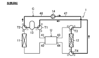
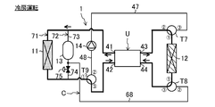
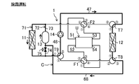
- FIG. 1 is a piping system diagram of the magnetic refrigeration apparatus according to the first embodiment.
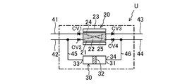
- FIG. 2 is a schematic configuration diagram of the magnetic refrigeration unit according to the first embodiment.
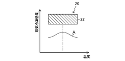
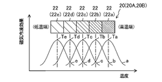
- FIG. 3 is a diagram schematically showing the relationship between the temperature of the single-layer magnetic refrigerating section according to the first embodiment and the magnetic refrigerating effect.
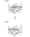
- FIG. 4 is a schematic configuration diagram of the magnetic refrigeration unit according to the first embodiment.
- FIG. 4 (A) shows the first operation
- FIG. 4 (B) shows the second operation.
- FIG. 5 is a schematic configuration diagram of the magnetic refrigeration unit according to the first embodiment.
- FIG. 5 (A) shows the third operation
- FIG. 5 (B) shows the fourth operation.
- FIG. 6 is a block diagram showing a relationship between a control device and a plurality of devices for which signals are exchanged between the control device.
- FIG. 7 is a piping system diagram for explaining the cooling operation in the magnetic refrigeration apparatus according to the first embodiment.
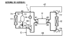
- FIG. 8 is a piping system diagram for explaining the heating operation in the magnetic refrigeration apparatus according to the first embodiment.
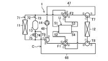
- FIG. 9 is a piping system diagram for explaining the defrosting operation in the magnetic refrigeration apparatus according to the first embodiment.
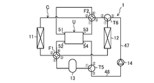
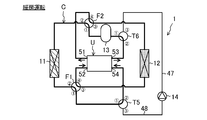
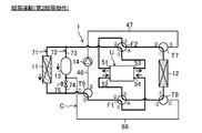
- FIG. 10 is a piping system diagram of the magnetic refrigeration apparatus according to the first modification of the first embodiment.
- FIG. 11 is a schematic configuration diagram of the magnetic refrigeration unit according to the first modification of the first embodiment.
- FIG. 12 is a diagram schematically showing the relationship between the temperature of the cascade-type magnetic refrigeration section and the magnetic refrigeration effect according to the first modification of the first embodiment.
- FIG. 13 is a schematic configuration diagram of the magnetic refrigeration unit according to the first modification of the first embodiment.
- FIG. 13 (A) shows the fifth operation
- FIG. 13 (B) shows the sixth operation.
- FIG. 14 is a piping system diagram for explaining the cooling operation in the magnetic refrigeration apparatus according to the first modification of the first embodiment.
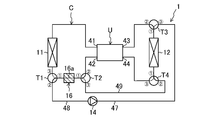
- FIG. 15 is a piping system diagram for explaining a heating operation in the magnetic refrigeration apparatus according to the first modification of the first embodiment.
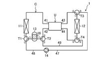
- FIG. 16 is a piping system diagram for explaining a defrosting operation in the magnetic refrigeration apparatus according to the first modification of the first embodiment.
- FIG. 17 is a piping system diagram for explaining a heating operation in the magnetic refrigeration apparatus according to the second modification of the first embodiment.
- FIG. 18 is a piping system diagram for explaining a defrosting operation in the magnetic refrigeration apparatus according to the second modification of the first embodiment.
- FIG. 19 is a piping system diagram for explaining a heating operation in the magnetic refrigeration apparatus according to the third modification of the first embodiment.
- FIG. 20 is a piping system diagram for explaining a defrosting operation in the magnetic refrigeration apparatus according to the third modification of the first embodiment.
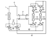
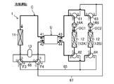
- FIG. 21 is a piping system diagram of the magnetic refrigeration apparatus according to the second embodiment.
- FIG. 22 is a piping system diagram for explaining the cooling operation in the magnetic refrigeration apparatus according to the second embodiment.
- FIG. 23 is a piping system diagram for explaining a heating operation (first heating operation) in the magnetic refrigeration apparatus according to the second embodiment.
- FIG. 24 is a piping system diagram for explaining a heating operation (second heating operation) in the magnetic refrigeration apparatus according to the second embodiment.
- FIG. 25 is a piping system diagram for explaining a defrosting operation (first defrosting operation) in the magnetic refrigerating apparatus according to the second embodiment.
- FIG. 26 is a piping system diagram for explaining a defrosting operation (second defrosting operation) in the magnetic refrigerating apparatus according to the second embodiment.
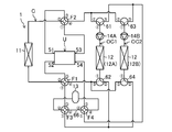
- FIG. 27 is a piping system diagram of the magnetic refrigeration apparatus according to the first modification of the second embodiment.
- FIG. 28 is a piping system diagram for explaining the cooling operation in the magnetic refrigeration apparatus according to the first modification of the second embodiment.
- FIG. 29 is a piping system diagram for explaining a heating operation (first heating operation) in the magnetic refrigeration apparatus according to the first modification of the second embodiment.
- FIG. 30 is a piping system diagram for explaining a heating operation (second heating operation) in the magnetic refrigeration apparatus according to the first modification of the second embodiment.
- FIG. 31 is a piping system diagram for explaining a defrosting operation (first defrosting operation) in the magnetic refrigeration apparatus according to the first modification of the second embodiment.
- FIG. 32 is a piping system diagram for explaining a defrosting operation (second defrosting operation) in the magnetic refrigeration apparatus according to the first modification of the second embodiment.
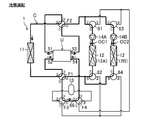
- FIG. 33 is a piping system diagram of the magnetic refrigeration apparatus according to the third embodiment.
- FIG. 34 is a piping system diagram for explaining the cooling operation in the magnetic refrigeration apparatus according to the third embodiment.
- FIG. 35 is a piping system diagram for explaining a heating operation (first heating operation) in the magnetic refrigeration apparatus according to the third embodiment.
- FIG. 36 is a piping system diagram for explaining a heating operation (second heating operation) in the magnetic refrigeration apparatus according to the third embodiment.
- FIG. 37 is a piping system diagram for explaining the defrosting operation in the magnetic refrigeration apparatus according to the third embodiment.
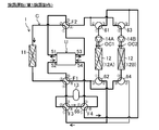
- FIG. 38 is a piping system diagram of the magnetic refrigeration apparatus according to the first modification of the third embodiment.
- FIG. 39 is a piping system diagram for explaining the cooling operation in the magnetic refrigeration apparatus according to the first modification of the third embodiment.
- FIG. 40 is a piping system diagram for explaining a heating operation (first heating operation) in the magnetic refrigeration apparatus according to the first modification of the third embodiment.
- FIG. 41 is a piping system diagram for explaining a heating operation (second heating operation) in the magnetic refrigeration apparatus according to the first modification of the third embodiment.
- FIG. 42 is a piping system diagram for explaining the defrosting operation in the magnetic refrigeration apparatus according to the first modification of the third embodiment.
- FIG. 43 is a piping system diagram of the magnetic refrigeration apparatus according to another first example.
- FIG. 44 is a piping system diagram of the magnetic refrigeration apparatus according to another second example.
- Embodiment 1 The magnetic refrigeration apparatus (1) of the present embodiment adjusts the temperature of the heat medium by utilizing the magnetic calorific value effect.
- the magnetic refrigerating device (1) is a solid refrigerating device that adjusts the temperature of the heat medium by utilizing the calorific value effect.
- the magnetic refrigeration system (1) is applied to, for example, an air conditioner.
- the magnetic refrigeration system (1) regulates the temperature of the air in the space to be air-conditioned.
- the space to be air-conditioned is an indoor space.
- the magnetic refrigeration system (1) switches between cooling operation and heating operation.
- the magnetic refrigeration apparatus (1) includes a heat medium circuit (C) filled with a heat medium.
- the filled heat medium is conveyed.
- the heat medium includes, for example, a refrigerant, water, brine and the like.
- the magnetic refrigeration system (1) includes a magnetic refrigeration unit (U), an indoor heat exchanger (11), an outdoor heat exchanger (12), a tank (13), a pump (14), and a switching mechanism (15). ) And a control device (100).
- the indoor heat exchanger (11) corresponds to the first heat exchanger and the outdoor heat exchanger (12) corresponds to the second heat exchanger.
- the tank (13) corresponds to the heat storage section.
- the pump (14) corresponds to the transport section.
- the magnetic refrigeration unit (U) includes a magnetic refrigeration section (20) as a solid refrigeration section, a reciprocating pump (30), a first outflow pipe (41), and a first inflow pipe ( It has a 42), a second outflow pipe (43), a second inflow pipe (44), a first pump side pipe (45), and a second pump side pipe (46).
- the first outflow pipe (41) corresponds to the first outflow portion
- the first inflow pipe (42) corresponds to the first inflow portion.
- the second outflow pipe (43) corresponds to the second outflow portion
- the second inflow pipe (44) corresponds to the second outflow portion.
- the magnetic refrigeration section (20) has a bed (21), a magnetic working substance (22) as a solid working substance, and a magnetic field modulation section (23) as an inducing section.
- the bed (21) is a hollow case or column.
- the inside of the bed (21) is filled with a magnetic working substance (22).
- the magnetic working substance (22) generates heat when a magnetic field is applied or when the applied magnetic field becomes stronger.
- the magnetic working substance (22) absorbs heat when the magnetic field is removed or the applied magnetic field weakens.
- Examples of the material of the magnetic working substance (22) include Gd 5 (Ge 0.5 Si 0.5 ) 4 , La (Fe 1-x Si x ) 13 , La (Fe 1-x Co x Si y ) 13 , and La (Fe 1-x Si y) 13. 1-x Si x ) 13 Hy , Mn (As 0.9 Sb 0.1 ) and the like can be used.
- the magnetic refrigeration unit (20) of this embodiment is a single layer type.
- the magnetic refrigeration unit (20) is composed of one kind of magnetic working substance (22).
- This one type of magnetic working substance (22) has a relationship between the temperature and the magnetic freezing effect, for example, as shown in curve A in FIG.
- the Curie temperature of this one type of magnetic working substance (22) is preferably set to the average temperature of the heat medium flowing through each internal flow path (24, 25).
- the Curie temperature is the temperature at which the magnetic freezing effect of the magnetic working substance is maximized.
- the magnetic field modulator (23) adjusts the strength of the magnetic field applied to the magnetic working substance (22).
- the magnetic field modulation section (33) is a trigger section that induces a calorific value effect on a magnetic working substance (22) as a solid refrigerant substance.
- the magnetic field modulator (23) is composed of, for example, an electromagnet capable of modulating the magnetic field.
- the magnetic field modulation unit (23) performs the first modulation operation and the second modulation operation. In the first modulation operation, a magnetic field is applied to the magnetic working substance (22), or the applied magnetic field is strengthened. In the second modulation operation, the magnetic field applied to the magnetic working substance (22) is removed or the applied magnetic field is weakened.
- a first internal flow path (24) and a second internal flow path (25) are formed inside the bed (21).
- a first outflow pipe (41) is connected to one end of the first internal flow path (24).
- a second inflow pipe (44) is connected to the other end of the first internal flow path (24).
- a first inflow pipe (42) is connected to one end of the second internal flow path (25).
- a second outflow pipe (43) is connected to the other end of the second internal flow path (25).
- the first check valve (CV1) is provided in the first outflow pipe (41).
- a second check valve (CV2) is provided in the first inflow pipe (42).
- the second outflow pipe (43) is provided with a third check valve (CV3).
- the second inflow pipe (44) is provided with a fourth check valve (CV4).
- the first check valve (CV1) allows the flow of heat medium in the direction from the first internal flow path (24) of the magnetic refrigeration section (20) toward the indoor heat exchanger (11), and heat in the opposite direction. Prohibit the flow of media.
- the second check valve (CV2) allows the flow of heat medium in the direction from the indoor heat exchanger (11) to the second internal flow path (25) of the magnetic refrigeration section (20), and heat in the opposite direction. Prohibit the flow of media.
- the third check valve (CV3) allows the flow of heat medium in the direction from the second internal flow path (25) of the magnetic refrigeration section (20) to the outdoor heat exchanger (12), and heat in the opposite direction. Prohibit the flow of media.
- the fourth check valve (CV4) allows the flow of heat medium in the direction from the outdoor heat exchanger (12) to the second internal flow path (25) of the magnetic refrigeration section (20), and heat in the opposite direction. Prohibit the flow of media.
- the reciprocating pump (30) reciprocally conveys the heat medium of the heat medium circuit (C).
- the reciprocating pump (30) corresponds to the reciprocating transport mechanism.
- the reciprocating pump (30) is composed of a piston pump.
- the reciprocating pump (30) has a pump case (31), a piston (32), and a drive mechanism (not shown).
- the piston (32) is located inside the pump case (31).
- the piston (32) divides the inside of the pump case (31) into two chambers.
- the reciprocating pump (30) is provided with a first port (33) and a second port (34). One chamber of the pump case (31) communicates with the first port (33) and the other chamber communicates with the second port (34).
- One end of the first pump side pipe (45) is connected to the first port (33).
- the other end of the first pump side pipe (45) is connected to the upstream side of the second check valve (CV2) of the first inflow pipe (42).
- One end of the second pump side pipe (46) is connected to the second port (34).
- the other end of the second pump side pipe (46) is connected to the upstream side of the fourth check valve (CV4) of the second inflow pipe (44).
- the drive mechanism has a rod connected to the piston (32), a crank connected to the rod, and an electric motor for driving the crank.
- the electric motor rotates and drives the crank, the rod moves forward and backward.
- the reciprocating motion of the piston (32) is performed in the pump case (31).
- the first transfer operation and the second transfer operation are alternately and repeatedly performed.
- the piston (32) moves to the first port (33) side.
- the heat medium is discharged from the first port (33).
- the discharged heat medium flows through the first inflow pipe (42), the second internal flow path (25), and the second outflow pipe (43) in this order.
- the piston (32) moves to the second port (34) side.
- the heat medium is discharged from the second port (34).
- the discharged heat medium flows through the second inflow pipe (44), the first internal flow path (24), and the first outflow pipe (41) in this order.
- the indoor heat exchanger (11) shown in FIG. 1 is a utilization heat exchanger.
- the indoor heat exchanger (11) exchanges heat between the heat medium and the indoor air.
- One end of the indoor heat exchanger (11) is connected to the first outflow pipe (41) via a pipe.
- the other end of the indoor heat exchanger (11) is connected to the third port of the first three-way valve (T1) via a pipe.
- the outdoor heat exchanger (12) is a heat source heat exchanger.
- the outdoor heat exchanger (12) exchanges heat between the heat medium and the outdoor air.
- One end of the outdoor heat exchanger (12) is connected to the first port of the third three-way valve (T3) via a pipe.
- the other end of the outdoor heat exchanger (12) is connected to the first port of the fourth three-way valve (T4) via a pipe.
- the tank (13) is a container for storing a heat medium.
- the tank (13) has two ports. One of these ports is connected to the first port of the first three-way valve (T1) via a pipe. The other of these ports is connected to the first port of the second three-way valve (T2) via a pipe.
- the tank (13) is arranged on the downstream side of the indoor heat exchanger (11) in the heating operation.
- the pump (14) carries the heat medium. Specifically, in the defrosting operation described in detail later, the pump (14) conveys the heat medium in the tank (13) to the outdoor heat exchanger (12) to be defrosted.
- One end of the discharge pipe (47) is connected to the discharge side of the pump (14). The other end of the discharge pipe (47) is connected to the third port of the third three-way valve (T3).
- One end of the suction pipe (48) is connected to the suction side of the pump (14). The other end of the suction pipe (48) is connected to the second port of the first three-way valve (T1).
- the switching mechanism switches the flow path of the heat medium of the heat medium circuit (C).
- the switching mechanism switches the flow path of the heat medium at least in the heating operation and the defrosting operation.
- the switching mechanism (15) of the present embodiment switches the flow path of the heat medium in the cooling operation, the heating operation, and the defrosting operation.
- the switching mechanism (15) is composed of various valves.
- the switching mechanism (15) includes a first three-way valve (T1), a second three-way valve (T2), a third three-way valve (T3), and a fourth three-way valve (T4).
- Each three-way valve (T1, T2, T3, T4) has a first port, a second port, and a third port, respectively.
- the first port of the three-way valve is a symbol with a circle around 1
- the second port of the three-way valve is a symbol with a circle around 2
- the third port of the three-way valve is a circle with a circle of 3. It is a symbol.
- Each three-way valve switches between the first state (the state shown by the solid line in FIG. 1) and the second state (the state shown by the broken line in FIG. 1).
- Each of the three-way valves (T1, T2, T3, T4) in the first state communicates the first port and the second port.
- Each of the three-way valves (T1, T2, T3, T4) in the second state communicates the first port and the third port.
- the first port of the first three-way valve (T1) communicates with the tank (13).
- the second port of the first three-way valve (T1) communicates with the suction pipe (48).
- the third port of the first three-way valve (T1) communicates with the indoor heat exchanger (11).
- the first port of the second three-way valve (T2) communicates with the tank (13).
- the second port of the second three-way valve (T2) communicates with the first inflow pipe (42).
- One end of the relay pipe (49) is connected to the third port of the second three-way valve (T2).
- the first port of the third three-way valve (T3) communicates with the outdoor heat exchanger (12).
- the second port of the third three-way valve (T3) communicates with the second outflow pipe (43).
- the third port of the third three-way valve (T3) communicates with the discharge pipe (47).
- the 1st port of the 4th three-way valve (T4) communicates with the outdoor heat exchanger (12).
- the other end of the relay pipe (49) is connected to the second port of the fourth three-way valve (T4).
- the third port of the fourth three-way valve (T4) communicates with the second inflow pipe (44).
- the control device (100) controls the magnetic refrigeration device (1).
- the control device (100) is configured by using a microcomputer and a memory device (specifically, a semiconductor memory) for storing software for operating the microcomputer.
- control device (100) is connected to the magnetic refrigeration unit (U), the pump (14), and the switching mechanism (15) via a communication line.
- the control device (100) controls the magnetic field modulator (23), the reciprocating pump (30), the pump (14), and the switching mechanism (15), respectively.
- the magnetic refrigerating device (1) performs a cooling operation, a heating operation, and a defrosting operation.
- the cooling operation the air in the indoor space is cooled.
- the cooling operation corresponds to the cooling operation.
- the heating operation the air in the indoor space is heated.
- the heating operation corresponds to the heating operation.
- the defrosting operation the frost in the outdoor heat exchanger (12) is melted.
- the first modulation operation of the magnetic field modulation unit (23) and the first transfer operation of the reciprocating pump (30) are performed at the same time.
- the heat medium is heated in the second internal flow path (25) of the magnetic refrigeration unit (20).
- the heated heat medium flows out of the second outflow pipe (43).
- the heat medium of the heat medium circuit (C) flows into the second port (34) of the pump case (31).
- the second modulation operation of the magnetic field modulation unit (23) and the second transfer operation of the reciprocating pump (30) are performed at the same time.
- the heat medium is cooled in the first internal flow path (24) of the magnetic refrigeration unit (20).
- the cooled heat medium flows out of the first outflow pipe (41).
- the heat medium of the heat medium circuit (C) flows into the first port (33) of the pump case (31).
- the first operation and the second operation are alternately repeated every second or so.
- the first three-way valve (T1) is in the second state
- the second three-way valve (T2) is in the first state
- the third three-way valve (T3) is in the first state
- the fourth three-way valve is in the first state.
- the valves (T4) are set to the second state respectively.
- the pump (14) stops.
- the switching mechanism (15) causes the heat medium cooled by the magnetic refrigeration section (20) to flow through the first outflow pipe (41), the indoor heat exchanger (11), and the first inflow pipe (42).
- the heat medium heated by the magnetic refrigeration section (20) forms a flow path through the second outflow pipe (43), the outdoor heat exchanger (12), and the second inflow pipe (44).
- the drawings show the flow of the heat medium in the first operation and the second operation in the same figure. Further, in the drawing, of the first heat exchanger (11) and the second heat exchanger (12), the heat exchanger through which the heat medium dissipates heat is hatched, and the heat exchanger on which the heat medium absorbs heat is marked with dots. are doing.
- the heat medium heated by the magnetic refrigeration unit (U) passes through the third three-way valve (T3) and flows through the outdoor heat exchanger (12). In the outdoor heat exchanger (12), the heat medium dissipates heat to the outdoor air. The heat medium radiated by the outdoor heat exchanger (12) passes through the fourth three-way valve (T4) and returns to the magnetic refrigeration unit (U).
- the heat medium cooled by the magnetic refrigeration unit (U) flows through the indoor heat exchanger (11).
- the heat medium absorbs heat from the indoor air.
- the indoor air is cooled.
- the heat medium absorbed by the indoor heat exchanger (11) passes through the first three-way valve (T1), the tank (13), and the second three-way valve (T2), and returns to the magnetic refrigeration unit (U).
- the second modulation operation of the magnetic field modulation unit (23) and the first transfer operation of the reciprocating pump (30) are performed at the same time.
- the heat medium is cooled in the second internal flow path (25) of the magnetic refrigeration unit (20).
- the cooled heat medium flows out of the second outflow pipe (43).
- the heat medium of the heat medium circuit (C) flows into the second port (34) of the pump case (31).
- the first modulation operation of the magnetic field modulation unit (23) and the second transfer operation of the reciprocating pump (30) are performed at the same time.
- the heat medium is heated in the first internal flow path (24) of the magnetic refrigeration unit (20).
- the heated heat medium flows out of the first outflow pipe (41).
- the heat medium of the heat medium circuit (C) flows into the first port (33) of the pump case (31).
- the first operation and the second operation are alternately repeated every second.
- the first three-way valve (T1) is in the second state
- the second three-way valve (T2) is in the first state
- the third three-way valve (T3) is in the first state
- the fourth three-way valve (T4) is set to the second state, respectively.
- the pump (14) stops.
- the switching mechanism (15) has the heat medium heated by the magnetic refrigeration section (20) as the first outflow pipe (41), the indoor heat exchanger (11), the tank (13) which is the heat storage section, and the first.
- the heat medium cooled by the magnetic refrigeration section (20) flows through the second outflow pipe (43), the outdoor heat exchanger (12), and the second inflow pipe (44).
- the heat medium cooled by the magnetic refrigerating section (20) in the third operation is endothermic by the outdoor heat exchanger (12), and the heat medium heated by the magnetic refrigerating section (20) in the third operation is used. Heat is dissipated by the indoor heat exchanger (11).
- the heat medium cooled by the magnetic refrigeration unit (U) passes through the third three-way valve (T3) and flows through the outdoor heat exchanger (12). In the outdoor heat exchanger (12), the heat medium absorbs heat from the outdoor air. The heat medium absorbed by the outdoor heat exchanger (12) passes through the fourth three-way valve (T4) and returns to the magnetic refrigeration unit (U).
- the heat medium heated by the magnetic refrigeration unit (U) flows through the indoor heat exchanger (11).
- the heat medium dissipates heat to the indoor air.
- the heat medium radiated by the indoor heat exchanger (11) passes through the first three-way valve (T1), the tank (13), and the second three-way valve (T2), and returns to the magnetic refrigeration unit (U).
- the heat medium heated by the magnetic refrigeration unit (U) is stored in the tank (13).
- the tank (13) stores the heat medium heated by the magnetic refrigeration unit (U).
- the tank (13) is located downstream of the indoor heat exchanger (11). Therefore, it is possible to suppress a decrease in the heating capacity of the indoor heat exchanger (11) due to the heat of the heat medium being stored in the tank (13). In particular, it is possible to suppress a decrease in the heating capacity at the start of the heating operation.
- the heat medium absorbs heat from the outdoor air in the outdoor heat exchanger (12). Therefore, frost may form on the surface of the outdoor heat exchanger (12).
- the defrosting operation is performed when the condition indicating that the surface of the outdoor heat exchanger (12) is frosted is satisfied.
- the magnetic refrigeration unit (U) In the defrosting operation shown in FIG. 9, the magnetic refrigeration unit (U) is stopped. In the defrosting operation, the first three-way valve (T1) is in the first state, the second three-way valve (T2) is in the second state, the third three-way valve (T3) is in the second state, and the fourth three-way valve (T4). ) Is set to the first state.
- the pump (14) operates.
- the switching mechanism (15) forms a flow path through which the heat medium of the tank (13), which is the heat storage unit, flows through the outdoor heat exchanger (12).
- This flow path is a circulation flow path including a pump (14), a discharge pipe (47), an outdoor heat exchanger (12), a relay pipe (49), a tank (13), and a suction pipe (48).
- the heat medium in the tank (13) passes through the first three-way valve (T1), the suction pipe (48), the discharge pipe (47), and the third three-way valve (T3) in that order, and the outdoor heat.
- the heat medium flowing inside the outdoor heat exchanger (12) melts the frost on the surface of the outdoor heat exchanger (12).
- the heat medium used for defrosting the outdoor heat exchanger (12) passes through the fourth three-way valve (T4) and returns to the tank (13).
- the heat stored in the tank (13) in the heating operation is used for defrosting the outdoor heat exchanger (12).
- Embodiment 1- The feature of this embodiment is the magnetic field modulation that imparts magnetic field fluctuation to the magnetic working material (22), the internal flow path (24,25) in which the magnetic working material (22) is arranged, and the magnetic working material (22).
- a magnetic refrigeration unit (20) having a unit (23), at least one first heat exchanger (11) (indoor heat exchanger), at least one second heat exchanger (12), and the first.
- the heat medium circuit (C) in which the heat exchanger (11), the second heat exchanger (12), and the internal flow paths (24, 25) are connected, and the heat medium of the heat medium circuit (C)
- a reciprocating transport mechanism (30) for reciprocating transport is provided, and the heat medium heated by the magnetic refrigerating section (20) is dissipated by the first heat exchanger (11) and cooled by the magnetic refrigerating section (20).
- a magnetic refrigeration apparatus that performs a heating operation in which the heat medium is absorbed by the second heat exchanger (12) and a defrosting operation in which the frost of the second heat exchanger (12) is melted. In the defrosting operation, the heat stored in the heat storage unit (13) is used to melt the frost in the second heat exchanger (12). is there.
- the heat of the heat medium in the heating operation (heating operation), can be stored in the heat storage unit (13).
- the heat stored in the heating operation can be used for defrosting the second heat exchanger (outdoor heat exchanger (12)), so that sufficient heat required for this defrosting can be secured.
- the heat storage unit includes a tank (13) for storing the heat medium heated by the magnetic refrigeration unit (20) in the heating operation, and the inside of the tank (13) in the defrosting operation. It is provided with a transport unit (14) (pump) for transporting the heat medium to the second heat exchanger (12).
- the heat of the heat medium in the heating operation, can be stored in the tank (13).
- the heat medium stored in the tank (13) during the heating operation can be transported to the outdoor heat exchanger (12) by the pump (14).
- the pump (14) As a result, sufficient heat required for defrosting the outdoor heat exchanger (12) can be secured.
- the size of the tank (13) can be appropriately changed according to the amount of heat required for defrosting the outdoor heat exchanger (12).
- the feature of this embodiment is that the heat medium heated by the magnetic refrigeration unit (20) flows through the indoor heat exchanger (11) and the heat storage unit (13) in the heating operation, and the heat storage unit (20) in the defrosting operation. It is provided with a switching mechanism (15) for switching the flow path of the heat medium circuit (C) so that the heat medium in 13) flows through the outdoor heat exchanger (12).
- the heating operation for storing the heat of the heat medium in the heat storage unit (13) and the defrosting operation for flowing the heat medium in the heat storage unit (13) to the outdoor heat exchanger (12) are switched. Can be done.
- the feature of this embodiment is that the heat storage unit (13) is arranged on the downstream side of the first heat exchanger (11) in the heat medium circuit (C) during the heating operation.
- the heat medium heated by the magnetic refrigeration section (20) flows through the indoor heat exchanger (11) and the heat storage section (13) in this order. Therefore, it is possible to suppress a decrease in the heating capacity of the indoor heat exchanger (11) due to the heat of the heat medium being stored in the heat storage unit (13).
- the temperature of the heat storage unit (13) may be low at the start of the heating operation.
- the start-up time of the heating operation may become long.
- the start-up time of the indoor heat exchanger (11) can be shortened.
- the feature of this embodiment is that the heat medium cooled by the magnetic refrigeration unit (20) is absorbed by the first heat exchanger (11) and the heat medium heated by the magnetic refrigeration unit (20) is subjected to the second heat exchange.
- the magnetic refrigerating unit (20) is a single-layer type composed of one kind of magnetic working material (22), and is configured to further perform a cooling operation for dissipating heat from the vessel (12), and the heat medium circuit (C).
- the switching mechanism (15) includes two inflow sections (44), and in the heating operation, the heat medium heated by the magnetic refrigeration section (20) is the first outflow section (41) and the first heat exchanger.
- the heat medium that flows through the heat storage section (13, 16) and the first inflow section (42) and is cooled by the magnetic refrigeration section (20) is the second outflow section (43) and the second outflow section (43). 2
- a flow path through the heat exchanger (12) and the second inflow section (44) is formed, and in the cooling operation, the heat medium cooled by the magnetic refrigeration section (20) is the first outflow section (41). )
- the first heat exchanger (11), and the first inflow section (42), and the heat medium heated by the magnetic refrigeration section (20) is the second outflow section (43) and the second.
- a flow path is formed through the heat exchanger (12) and the second inflow section (44), and in the defrosting operation, the heat medium of the heat storage section (13, 16) is the second heat exchanger (12). ) Is formed.
- the above-mentioned cooling operation, heating operation, and defrosting operation can be switched.
- ⁇ Modification 1 of Embodiment 1> In the first modification of the first embodiment, a so-called cascade type magnetic refrigeration unit (20) is used. As shown in FIGS. 10 and 11, the configuration of the magnetic refrigeration apparatus (1) of this modified example is different from the configuration of the magnetic refrigeration unit (U) and the heat medium circuit (C). The points that differ mainly from the embodiments will be described below.
- the magnetic refrigeration unit (U) has two magnetic refrigeration units (20). Specifically, the two magnetic refrigeration units (20) are composed of a first magnetic refrigeration unit (20A) and a second magnetic refrigeration unit (20B). Each magnetic refrigeration unit (20) has a bed (21) and a magnetic field modulation unit (23), respectively, as in the first embodiment. A first internal flow path (24) and a second internal flow path (25) are formed in each magnetic refrigeration unit (20), respectively.
- the magnetic refrigeration section (20) of the modified example is a cascade type having a plurality of types of magnetic working substances (22). As shown in FIG. 12, the magnetic refrigeration section (20) of this example is composed of, for example, five types of magnetic working substances (22). In the magnetic refrigeration section (20), from the high temperature end to the low temperature end, the first magnetic working substance (22a), the second magnetic working substance (22b), the third magnetic working substance (22c), and the fourth magnetic working substance. (22d) and the fifth magnetic working substance (22e) are composed in this order.
- the temperature of each magnetic working substance (22) and the characteristics of the magnetic refrigeration effect are different from each other. Specifically, these magnetic working substances (22) have different Curie temperatures from each other.
- the Curie temperature of the first magnetic working material (22a) is Ta
- the Curie temperature of the second magnetic working material (22b) is Tb
- the Curie temperature of the third magnetic working material (22c) is Tc
- the curie temperature of the fourth magnetic working material (22d) Assuming that the Curie temperature is Td and the fifth magnetic working substance (22e) is Te, the relationship of Ta> Tb> Tc> Td> Te is satisfied.
- the magnetic refrigeration unit (U) has a low temperature outflow pipe (51), a low temperature inflow pipe (52), a high temperature outflow pipe (53), a high temperature inflow pipe (54), and a unit side pump (55).
- the magnetic refrigeration unit (U) has a low temperature first three-way valve (56), a low temperature second three-way valve (57), a high temperature first three-way valve (58), and a high temperature second three-way valve (59).
- the low temperature outflow pipe (51) corresponds to the low temperature outflow part
- the low temperature inflow pipe (52) corresponds to the low temperature inflow part.
- the high temperature outflow pipe (53) corresponds to the high temperature outflow part
- the high temperature inflow pipe (54) corresponds to the high temperature inflow part.
- the reciprocating transfer mechanism (50) is configured by these three-way valves (56,57,58,59) and the unit-side pump (55).
- the unit side pump (55) is installed in the high temperature outflow pipe (53).
- the unit-side pump (55) is a one-way pump.
- the unit-side pump (55) conveys the heat medium toward the downstream side of the high-temperature outflow pipe (53).
- each three-way valve (56,57,58,59) is the same as the configuration of the three-way valve described above.
- the first port of the low temperature first three-way valve (56) communicates with the low temperature outflow pipe (51).
- the second port of the low temperature first three-way valve (56) communicates with the low temperature end of the first internal flow path (24) of the second magnetic refrigeration section (20B).
- the third port of the low temperature first three-way valve (56) communicates with the low temperature end of the first internal flow path (24) of the first magnetic refrigeration section (20A).
- the first port of the low temperature second three-way valve (57) communicates with the low temperature inflow pipe (52).
- the second port of the low temperature second three-way valve (57) communicates with the low temperature end of the second internal flow path (25) of the second magnetic refrigeration section (20B).
- the third port of the low temperature second three-way valve (57) communicates with the low temperature end of the second internal flow path (25) of the first magnetic refrigeration section (20A).
- the first port of the high temperature first three-way valve (58) communicates with the high temperature outflow pipe (53).
- the second port of the high temperature first three-way valve (58) communicates with the high temperature end of the second internal flow path (25) of the second magnetic refrigeration section (20B).
- the third port of the high temperature first three-way valve (58) communicates with the high temperature end of the second internal flow path (25) of the first magnetic refrigeration section (20A).
- the first port of the high temperature second three-way valve (59) communicates with the high temperature inflow pipe (54).
- the second port of the high temperature second three-way valve (59) communicates with the high temperature end of the first internal flow path (24) of the second magnetic refrigeration section (20B).
- the third port of the high temperature second three-way valve (59) communicates with the high temperature end of the first internal flow path (24) of the first magnetic refrigeration section (20A).
- the switching mechanism (15) of this modified example includes a fifth three-way valve (T5), a sixth three-way valve (T6), a first four-way switching valve (F1), and a second four-way switching valve (T5).
- Has F2 The configuration of each three-way valve (T5) is the same as the configuration of the three-way valve described above.
- Each four-way switching valve (F1, F2) has a first port, a second port, a third port, and a fourth port, respectively.
- the first port of the four-way switching valve is a symbol with a circle around 1
- the second port of the four-way switching valve is a symbol with a circle around 2
- the third port of the four-way switching valve is a circle with a three. The symbol is circled, and the 4th port of the four-way switching valve is circled 4.
- Each four-way switching valve (F1, F2) switches between the first state (the state shown by the solid line in FIG. 1) and the second state (the state shown by the broken line in FIG. 1).
- Each of the four-way switching valves (F1 and F2) in the first state communicates the first port and the second port, and at the same time communicates the third port and the fourth port.
- Each of the four-way switching valves (F1 and F2) in the second state communicates the first port and the third port, and at the same time communicates the second port and the fourth port.
- the 1st port of the 5th three-way valve (T5) communicates with the tank (13).
- the second port of the fifth three-way valve (T5) communicates with the high temperature inflow pipe (54).
- the third port of the fifth three-way valve (T5) communicates with the suction pipe (48).
- the 1st port of the 6th three-way valve (T6) communicates with the outdoor heat exchanger (12).
- the second port of the sixth three-way valve (T6) communicates with the third port of the second four-way switching valve (F2).
- the third port of the sixth three-way valve (T6) communicates with the discharge pipe (47).
- the first port of the first four-way switching valve (F1) communicates with the tank (13).
- the second port of the first four-way switching valve (F1) communicates with the indoor heat exchanger (11).
- the third port of the first four-way switching valve (F1) communicates with the outdoor heat exchanger (12).
- the fourth port of the first four-way switching valve (F1) communicates with the low temperature inflow pipe (52).
- the first port of the second four-way switching valve (F2) communicates with the high temperature outflow pipe (53).
- the second port of the second four-way switching valve (F2) communicates with the indoor heat exchanger (11).
- the fourth port of the second four-way switching valve (F2) communicates with the low temperature outflow pipe (51).
- the magnetic refrigeration device (1) of this modified example has the same control device (100) as that of the embodiment.
- the configuration of the control device (100) is the same as that of the above embodiment. In FIG. 10 and other related drawings, the control device (100) is not shown.
- the magnetic refrigerating apparatus (1) of the first modification of the first embodiment performs a cooling operation, a heating operation, and a defrosting operation.
- the first magnetic refrigeration unit (20A) performs the first modulation operation
- the second magnetic refrigeration unit (20B) performs the second modulation operation.
- the low temperature first three-way valve (56) is in the first state
- the low temperature second three-way valve (57) is in the second state
- the high temperature first three-way valve (58) is in the second state
- the high temperature second three-way valve (59). are set to the first state respectively.
- the unit side pump (55) operates.
- the first magnetic refrigeration unit (20A) performs the second modulation operation
- the second magnetic refrigeration unit (20B) performs the first modulation operation.
- the low temperature first three-way valve (56) is in the second state
- the low temperature second three-way valve (57) is in the first state
- the high temperature first three-way valve (58) is in the first state
- the high temperature second three-way valve (59). are set to the second state respectively.
- the unit side pump (55) operates.
- the fifth three-way valve (T5) is in the first state
- the sixth three-way valve (T6) is in the first state
- the first four-way switching valve (F1) is in the second state.
- the second four-way switching valve (F2) is set to the second state.
- the switching mechanism (15) allows the heat medium cooled by each magnetic refrigeration unit (20) to flow through the low temperature outflow pipe (51), the indoor heat exchanger (11), and the low temperature inflow pipe (52).
- the heat medium heated by each magnetic refrigeration unit (20) forms a flow path through the high temperature outflow pipe (53), the outdoor heat exchanger (12), and the high temperature inflow pipe (54).
- the heat medium heated by the magnetic refrigeration unit (U) passes through the second four-way switching valve (F2) and the sixth three-way valve (T6), and flows through the outdoor heat exchanger (12).
- the heat medium dissipates heat to the outdoor air.
- the heat medium radiated by the outdoor heat exchanger (12) passes through the first four-way switching valve (F1), the tank (13), and the fifth three-way valve (T5), and returns to the magnetic refrigeration unit (U).
- the heat medium cooled by the magnetic refrigeration unit (U) passes through the second four-way switching valve (F2) and flows through the indoor heat exchanger (11).
- the heat medium absorbs heat from the indoor air.
- the indoor air is cooled.
- the heat medium absorbed by the indoor heat exchanger (11) passes through the first four-way switching valve (F1) and returns to the magnetic refrigeration unit (U).
- the fifth three-way valve (T5) is in the first state
- the sixth three-way valve (T6) is in the first state
- the first four-way switching valve (F1) is in the first state.
- the second four-way switching valve (F2) is set to the first state.
- the switching mechanism (15) uses the heat medium heated by each magnetic refrigeration unit (20) as a high-temperature outflow pipe (53), indoor heat exchanger (11), tank (13), and high-temperature inflow pipe (54). ), And the heat medium cooled by each magnetic refrigeration unit (20) forms a flow path through the low temperature outflow pipe (51), the outdoor heat exchanger (12), and the low temperature inflow pipe (52).
- the heat medium cooled by the magnetic refrigeration unit (U) passes through the second four-way switching valve (F2) and the sixth three-way valve (T6), and flows through the outdoor heat exchanger (12).
- the heat medium absorbs heat from the outdoor air.
- the heat medium absorbed by the outdoor heat exchanger (12) passes through the first four-way switching valve (F1) and returns to the magnetic refrigeration unit (U).
- the heat medium heated by the magnetic refrigeration unit (U) passes through the second four-way switching valve (F2) and flows through the indoor heat exchanger (11).
- the heat medium dissipates heat to the indoor air.
- the heat medium radiated by the indoor heat exchanger (11) passes through the first four-way switching valve (F1), the tank (13), and the fifth three-way valve (T5), and returns to the magnetic refrigeration unit (U).
- the heat medium heated by the magnetic refrigeration unit (U) is stored in the tank (13).
- the tank (13) stores the heat of the heat medium heated by the magnetic refrigeration unit (U).
- the switching mechanism (15) forms a flow path through which the heat medium of the tank (13), which is the heat storage unit, flows through the outdoor heat exchanger (12).
- This flow path is a circulation flow path including a pump (14), a discharge pipe (47), an outdoor heat exchanger (12), a tank (13), and a suction pipe (48).
- the heat medium in the tank (13) passes through the fifth three-way valve (T5), the suction pipe (48), the discharge pipe (47), and the sixth three-way valve (T6) in this order. , Flows through the outdoor heat exchanger (12). In the outdoor heat exchanger (12), the heat medium flowing inside the outdoor heat exchanger (12) melts the frost on the surface of the outdoor heat exchanger (12). The heat medium used for defrosting the outdoor heat exchanger (12) passes through the first four-way switching valve (F1) and returns to the tank (13).
- the heat stored in the tank (13) in the heating operation is used for defrosting the outdoor heat exchanger (12).
- the feature of this embodiment is that the heat medium cooled by the magnetic refrigeration unit (20) is absorbed by the first heat exchanger (11) and the heat medium heated by the magnetic refrigeration unit (20) is subjected to the second heat exchange.
- the magnetic refrigerating section (20) is a cascade type composed of a plurality of types of magnetic working materials (22), and the heat medium circuit (C) is configured to further perform a cooling operation in which heat is dissipated by the vessel (12).
- the switching mechanism (15) includes the high temperature outflow portion (53), the first heat exchanger (11), and the heat medium heated by the magnetic refrigeration unit (20).
- the heat medium that flows through the heat storage section (13, 16) and the high temperature inflow section (54) and is cooled by the magnetic refrigeration section (20) is the low temperature outflow section (51) and the second heat exchanger (12).
- the heat medium cooled by the magnetic refrigeration section (20) in the cooling operation is formed by the low temperature outflow section (51) and the first heat exchanger (1st heat exchanger).
- the heat medium heated by the magnetic refrigeration section (20) flows through the low temperature inflow section (52) and the high temperature outflow section (53), the second heat exchanger (12), and the high temperature inflow section.
- a flow path through the section (54) is formed, and in the defrosting operation, the heat medium of the heat storage section (13, 16) forms a flow path through the second heat exchanger (12).
- the above-mentioned cooling operation, heating operation, and defrosting operation can be switched.
- the second modification of the first embodiment has a different configuration of the heat medium circuit (C) from the first embodiment.
- the configuration of the magnetic refrigeration unit (U) of this modification is the same as the configuration of the first embodiment.
- the magnetic refrigeration section (20) of this modification is a single-layer type.
- the first three-way valve (T1), the tank (13), and the second three-way valve (T2) are indoor heat exchangers. It is located on the upstream side of (11).
- the first three-way valve (T1) is in the second state
- the second three-way valve (T2) is in the first state
- the third three-way valve (T3) is in the first state
- the fourth three-way valve is in the first state.
- the valves (T4) are set to the second state respectively.
- the magnetic refrigeration unit (U) alternately performs the third operation and the fourth operation.
- the pump (14) stops.
- the heat medium heated by the magnetic refrigeration unit (U) passes through the first three-way valve (T1), the tank (13), and the second three-way valve (T2), and flows through the indoor heat exchanger (11).
- the tank (13) is located upstream of the indoor heat exchanger (11). Therefore, the heat of the heat medium can be reliably stored in the tank (13).
- the heat medium radiated by the indoor heat exchanger (11) returns to the magnetic refrigeration unit (U).
- the heat medium cooled by the magnetic refrigeration unit (U) passes through the third three-way valve (T3) and absorbs heat in the outdoor heat exchanger (12). This heat medium passes through the fourth three-way valve (T4) and returns to the magnetic refrigeration unit (U).
- the first three-way valve (T1) is in the first state
- the second three-way valve (T2) is in the second state
- the third three-way valve (T3) is in the second state
- the three-way valve (T4) is set to the first state respectively.
- the magnetic refrigeration unit (U) stops.
- the pump (14) operates.
- the heat medium in the tank (13) passes through the second three-way valve (T2), the suction pipe (48), the discharge pipe (47), and the third three-way valve (T3) in this order, and passes through the outdoor heat exchanger (12). It flows. In the outdoor heat exchanger (12), the heat medium melts the frost.
- the heat medium used for defrosting the outdoor heat exchanger (12) passes through the fourth three-way valve (T4) and the first three-way valve (T1) and returns to the tank (13).
- the modified example 3 of the first embodiment has a different configuration of the heat medium circuit (C) from the modified example 1 of the first embodiment.
- the configuration of the magnetic refrigeration unit (U) of this modification is the same as the configuration of modification 1 of the first embodiment.
- the magnetic refrigeration section (20) of this modification is a cascade type. As shown in FIG. 19, in the heat medium circuit (C) of this modified example, in the heating operation, the sixth three-way valve (T6), the tank (13), and the second four-way switching valve (F2) exchange indoor heat. It is placed on the upstream side of the vessel (11).
- the fifth three-way valve (T5) is in the first state
- the sixth three-way valve (T6) is in the first state
- the first four-way switching valve (F1) is in the first state
- the second state is in the first state
- the four-way switching valve (F2) is set to the first state respectively.
- the magnetic refrigeration unit (U) alternately performs the fifth operation and the sixth operation.
- the pump (14) stops.
- the heat medium heated by the magnetic refrigeration unit (U) passes through the 6th three-way valve (T6), the tank (13), and the 2nd four-way switching valve (F2), and flows through the indoor heat exchanger (11).
- the tank (13) is located upstream of the indoor heat exchanger (11). Therefore, the heat of the heat medium can be reliably stored in the tank (13).
- the heat medium radiated by the indoor heat exchanger (11) passes through the first four-way switching valve (F1) and the fifth three-way valve (T5) in this order, and returns to the magnetic refrigeration unit (U).
- the heat medium cooled by the magnetic refrigeration unit (U) passes through the second four-way switching valve (F2) and absorbs heat in the outdoor heat exchanger (12). This heat medium passes through the first four-way switching valve (F1) and returns to the magnetic refrigeration unit (U).
- the fifth three-way valve (T5) is in the second state
- the sixth three-way valve (T6) is in the second state
- the first four-way switching valve (F1) is in the second state.
- the four-way switching valve (F2) is set to the second state, respectively.
- the magnetic refrigeration unit (U) stops.
- the pump (14) operates.
- the heat medium in the tank (13) passes through the second four-way switching valve (F2) and flows through the outdoor heat exchanger (12). In the outdoor heat exchanger (12), the heat medium melts the frost.
- the heat medium used for defrosting the outdoor heat exchanger (12) passes through the first four-way switching valve (F1), the fifth three-way valve (T5), and the sixth three-way valve (T6), and passes through the tank (13).
- the magnetic refrigeration apparatus (1) according to the second embodiment has a plurality of outdoor heat exchangers (12). In the defrosting operation, a defrosting operation is performed in which a plurality of outdoor heat exchangers (12) are individually defrosted.
- the configuration of the magnetic refrigeration unit (U) of the second embodiment is the same as the configuration of the first embodiment.
- the magnetic refrigeration unit (U) has a single-layer magnetic refrigeration unit (20).
- the switching mechanism (15) of the second embodiment is a third four-way switching valve (F3), a fourth four-way switching valve (F4), a first suction three-way valve (61), and a first discharge three-way valve. (62), a second suction three-way valve (63), and a second discharge three-way valve (64) are included.
- the first port of the third four-way switching valve (F3) communicates with each second port of the first discharge three-way valve (62) and the second discharge three-way valve (64) via the first relay pipe (65). ..
- the second port (34) of the third four-way switching valve (F3) communicates with the tank (13).
- the third port of the third four-way switching valve (F3) communicates with the indoor heat exchanger (11).
- the fourth port of the third four-way switching valve (F3) communicates with the second port of the fourth four-way switching valve (F4) via the bypass pipe (66).
- the bypass pipe (66) corresponds to the bypass flow path that bypasses the tank (13) in the first heating operation.
- the first port of the fourth four-way switching valve (F4) communicates with each third port of the first suction three-way valve (61) and the second suction three-way valve (63) via the second relay pipe (67). ..
- the third port of the fourth four-way switching valve (F4) communicates with the first inflow pipe (42).
- the fourth port of the fourth four-way switching valve (F4) communicates with the tank (13).
- the two outdoor circuits are connected in parallel to the heat medium circuit (C).
- the two outdoor circuits are composed of a first outdoor circuit (OC1) and a second outdoor circuit (OC2).
- the heat medium circuit (C) may have three or more outdoor circuits.
- the first outdoor circuit (OC1) is provided with a first outdoor heat exchanger (12A), a first pump (14A), a first suction three-way valve (61), and a first discharge three-way valve (62). Be done.
- the first outdoor heat exchanger (12A) is arranged on the discharge side of the first pump (14A).
- the first suction three-way valve (61) is arranged on the suction side of the first pump (14A).
- the first port of the first suction three-way valve (61) communicates with the first pump (14A).
- the second port of the first suction three-way valve (61) communicates with the second outflow pipe (43).
- the first port of the first discharge three-way valve (62) communicates with the first outdoor heat exchanger (12A).
- the third port of the first discharge three-way valve (62) communicates with the second inflow pipe (44).
- the second outdoor circuit (OC2) is provided with a second outdoor heat exchanger (12B), a second pump (14B), a second suction three-way valve (63), and a second discharge three-way valve (64). Be done.
- the second outdoor heat exchanger (12B) is arranged on the discharge side of the second pump (14B).
- a second suction three-way valve (63) is arranged on the suction side of the second pump (14B).
- the first port of the second suction three-way valve (63) communicates with the second pump (14B).
- the second port of the second suction three-way valve (63) communicates with the second outflow pipe (43).
- the first port of the second discharge three-way valve (64) communicates with the second outdoor heat exchanger (12B).
- the third port of the second discharge three-way valve (64) communicates with the second inflow pipe (44).
- the magnetic refrigerating apparatus (1) of the second embodiment performs a cooling operation, a heating operation, and a defrosting operation.
- the heating operation includes a first heating operation and a second heating operation.
- the defrosting operation includes a first defrosting operation and a second defrosting operation.
- the third four-way switching valve (F3) is in the first state
- the fourth four-way switching valve (F4) is in the second state
- the first suction three-way valve (61) is in the first state.
- the first discharge three-way valve (62) is set to the second state
- the second suction three-way valve (63) is set to the first state
- the second discharge three-way valve (64) is set to the second state.
- the first pump (14A) and the second pump (14B) are stopped.
- the first pump (14A) and the second pump (14B) may be operated.
- the heat medium heated by the magnetic refrigeration unit (U) flows in parallel with the first outdoor circuit (OC1) and the second outdoor circuit (OC2).
- the first outdoor circuit (OC1) the heat medium passes through the first suction three-way valve (61) and dissipates heat in the first outdoor heat exchanger (12A).
- the heat medium radiated by the first outdoor heat exchanger (12A) passes through the first discharge three-way valve (62) and returns to the magnetic refrigeration unit (U).
- the heat medium passes through the second suction three-way valve (63) and dissipates heat in the second outdoor heat exchanger (12B).
- the heat medium radiated by the second outdoor heat exchanger (12B) passes through the second discharge three-way valve (64) and returns to the magnetic refrigeration unit (U).
- the heat medium cooled by the magnetic refrigeration unit (U) flows through the indoor heat exchanger (11).
- the heat medium absorbs heat from the indoor air.
- the heat medium absorbed by the indoor heat exchanger (11) flows through the third four-way switching valve (F3), the bypass pipe (66), and the fourth four-way switching valve (F4), and returns to the magnetic refrigeration unit (U).
- the heating operation includes a first heating operation and a second heating operation.
- the first heating operation is executed at the start of the heating operation.
- the first heating operation is executed in a period after the command for executing the heating operation is received by the control device (100) until the condition for the heating operation to reach the steady operation is satisfied.
- This condition is, for example, that the suction temperature of the indoor heat exchanger (11) reaches a predetermined temperature.
- the second heating operation is executed.
- the third four-way switching valve (F3) is in the first state
- the fourth four-way switching valve (F4) is in the second state
- the first suction three-way valve (61) is in the first state.
- the first discharge three-way valve (62) is set to the second state
- the second suction three-way valve (63) is set to the first state
- the second discharge three-way valve (64) is set to the second state.
- the first pump (14A) and the second pump (14B) are stopped.
- the first pump (14A) and the second pump (14B) may be operated.
- the heat medium cooled by the magnetic refrigeration unit (U) flows in parallel with the first outdoor circuit (OC1) and the second outdoor circuit (OC2).
- the first outdoor circuit (OC1) the heat medium passes through the first suction three-way valve (61) and is endothermic in the first outdoor heat exchanger (12A).
- the heat medium absorbed by the first outdoor heat exchanger (12A) passes through the first discharge three-way valve (62) and returns to the magnetic refrigeration unit (U).
- the second outdoor circuit (OC2) the heat medium passes through the second suction three-way valve (63) and is endothermic in the second outdoor heat exchanger (12B).
- the heat medium absorbed by the second outdoor heat exchanger (12B) passes through the second discharge three-way valve (64) and returns to the magnetic refrigeration unit (U).
- the heat medium heated by the magnetic refrigeration unit (U) flows through the indoor heat exchanger (11).
- the heat medium dissipates heat to the indoor air.
- the heat medium radiated by the indoor heat exchanger (11) flows through the third four-way switching valve (F3), the bypass pipe (66), and the fourth four-way switching valve (F4), and returns to the magnetic refrigeration unit (U).
- the heat medium heated by the magnetic refrigeration unit (U) bypasses the tank (13) and returns to the magnetic refrigeration unit (U). Therefore, the heat of the heat medium is not stored in the tank (13). Therefore, the heating capacity of the indoor heat exchanger (11) can be quickly improved, and the start-up time of the heating operation can be shortened.
- the third four-way switching valve (F3) is in the second state
- the fourth four-way switching valve (F4) is in the first state
- the first suction three-way valve (61) is in the first state.
- the first discharge three-way valve (62) is set to the second state
- the second suction three-way valve (63) is set to the first state
- the second discharge three-way valve (64) is set to the second state.
- the first pump (14A) and the second pump (14B) are stopped.
- the first pump (14A) and the second pump (14B) may be operated.
- the heat medium cooled by the magnetic refrigeration unit (U) flows in parallel with the first outdoor circuit (OC1) and the second outdoor circuit (OC2).
- the first outdoor circuit (OC1) the heat medium passes through the first suction three-way valve (61) and is endothermic in the first outdoor heat exchanger (12A).
- the heat medium absorbed by the first outdoor heat exchanger (12A) passes through the first discharge three-way valve (62) and returns to the magnetic refrigeration unit (U).
- the second outdoor circuit (OC2) the heat medium passes through the second suction three-way valve (63) and is endothermic in the second outdoor heat exchanger (12B).
- the heat medium absorbed by the second outdoor heat exchanger (12B) passes through the second discharge three-way valve (64) and returns to the magnetic refrigeration unit (U).
- the heat medium heated by the magnetic refrigeration unit (U) flows through the indoor heat exchanger (11).
- the heat medium dissipates heat to the indoor air.
- the heat medium radiated by the indoor heat exchanger (11) flows through the tank (13).
- the heat of the heat medium is stored.
- the heat medium flowing through the tank (13) returns to the magnetic refrigeration unit (U).
- the defrosting operation includes a first defrosting operation and a second defrosting operation.
- the outdoor heat exchanger (12) to be defrosted and the outdoor heat exchanger (12) that absorbs heat from the heat medium are different from each other.
- the first defrosting operation and the second defrosting operation are performed at least once.
- the first outdoor heat exchanger (12A) is targeted for defrosting, and the heat medium absorbs heat in the second outdoor heat exchanger (12B).
- the second outdoor heat exchanger (12B) is targeted for defrosting, and the heat medium absorbs heat in the first outdoor heat exchanger (12A).
- the heat medium heated by the magnetic refrigeration unit (20) is dissipated by the indoor heat exchanger (11), and the heat medium cooled by the magnetic refrigeration unit (20) is dissipated by some outdoor heat exchangers (20).
- the operation of absorbing heat in 12) and the operation of supplying the heat medium of the tank (13) to the other outdoor heat exchanger (12) to be defrosted are executed at the same time.
- the third four-way switching valve (F3) is in the first state
- the fourth four-way switching valve (F4) is in the second state
- the first suction three-way valve (61) is in the second state.
- the first discharge three-way valve (62) is set to the first state
- the second suction three-way valve (63) is set to the first state
- the second discharge three-way valve (64) is set to the second state.
- the first pump (14A) operates.
- the second pump (14B) stops.
- the second pump (14B) may be operated.
- the heat medium cooled by the magnetic refrigeration unit (U) flows through the second outdoor circuit (OC2).
- the heat medium passes through the second suction three-way valve (63) and is endothermic in the second outdoor heat exchanger (12B).
- the heat medium absorbed by the second outdoor heat exchanger (12B) passes through the second discharge three-way valve (64) and returns to the magnetic refrigeration unit (U).
- the heat medium heated by the magnetic refrigeration unit (U) flows through the indoor heat exchanger (11).
- the heat medium dissipates heat to the indoor air.
- the heat medium radiated by the indoor heat exchanger (11) flows through the third four-way switching valve (F3), the bypass pipe (66), and the fourth four-way switching valve (F4), and returns to the magnetic refrigeration unit (U).
- the heat medium in the tank (13) passes through the 4th 4-way switching valve (F4) and the 1st suction 3-way valve (61), and flows through the 1st outdoor heat exchanger (12A).
- the heat medium flowing inside the first outdoor heat exchanger (12A) melts the frost on the surface of the first outdoor heat exchanger (12A).
- the heat medium used for defrosting the first outdoor heat exchanger (12A) passes through the first discharge three-way valve (62) and the third four-way switching valve (F3), and returns to the tank (13).
- the third four-way switching valve (F3) is in the first state
- the fourth four-way switching valve (F4) is in the second state
- the first suction three-way valve (61) is in the first state
- the first discharge three-way valve (62) is set to the second state
- the second suction three-way valve (63) is set to the second state
- the second discharge three-way valve (64) is set to the first state.
- the second pump (14B) operates.
- the first pump (14A) stops.
- the first pump (14A) may be operated.
- the heat medium cooled by the magnetic refrigeration unit (U) flows through the first outdoor circuit (OC1).
- the heat medium passes through the first suction three-way valve (61) and is endothermic in the first outdoor heat exchanger (12A).
- the heat medium absorbed by the first outdoor heat exchanger (12A) passes through the first discharge three-way valve (62) and returns to the magnetic refrigeration unit (U).
- the heat medium heated by the magnetic refrigeration unit (U) flows through the indoor heat exchanger (11).
- the heat medium dissipates heat to the indoor air.
- the heat medium radiated by the indoor heat exchanger (11) flows through the third four-way switching valve (F3), the bypass pipe (66), and the fourth four-way switching valve (F4), and returns to the magnetic refrigeration unit (U).
- the heat medium in the tank (13) passes through the 4th four-way switching valve (F4) and the second suction three-way valve (63), and flows through the second outdoor heat exchanger (12B).
- the heat medium flowing inside the second outdoor heat exchanger (12B) melts the frost on the surface of the second outdoor heat exchanger (12B).
- the heat medium used for defrosting the second outdoor heat exchanger (12B) passes through the second discharge three-way valve (64) and the third four-way switching valve (F3), and returns to the tank (13).
- the at least one second heat exchanger (12) is composed of a plurality of second heat exchangers (12), and the defrosting operation is the second heat exchanger to be defrosted. (12) and a plurality of defrosting operations for changing the second heat exchanger (12) for absorbing heat of the heat medium are included, and in each of the defrosting operations, the heat medium heated by the magnetic refrigerating unit (20) is described.
- the operation of supplying the heat medium of the heat storage unit (13, 16) to the second heat exchanger (12) is executed at the same time.
- the air can be heated by the first heat exchanger (11) while defrosting the second heat exchanger (12) to be defrosted.
- the outdoor heat exchanger (12) to be defrosted can be defrosted and the heating operation can be continued.
- the defrosting operation all the outdoor heat exchangers (12) can be defrosted by performing a plurality of defrosting operations.
- the magnetic refrigeration apparatus (1) of the first modification of the second embodiment shown in FIG. 27 has a so-called cascade type magnetic refrigeration unit (20).
- the configuration of the magnetic refrigeration unit (U) of the first modification of the second embodiment is the same as the configuration of the magnetic refrigeration unit (U) of the first modification of the first embodiment.
- the switching mechanism (15) of this modification has a first four-way switching valve (F1) and a second four-way switching valve (F2), as in the first modification of the first embodiment.
- the first port of the first four-way switching valve (F1) communicates with the third port of the third four-way switching valve (F3).
- the second port of the first four-way switching valve (F1) communicates with the indoor heat exchanger (11).
- the third port of the first four-way switching valve (F1) communicates with the low temperature inflow pipe (52).
- the fourth port of the first four-way switching valve (F1) communicates with the third port of the first discharge three-way valve (62) and the third port of the second discharge three-way valve (64), respectively.
- the first port of the second four-way switching valve (F2) communicates with the high temperature outflow pipe (53).
- the second port of the second four-way switching valve (F2) communicates with the indoor heat exchanger (11).
- the third port of the second four-way switching valve (F2) communicates with the low temperature outflow pipe (51).
- the fourth port of the second four-way switching valve (F2) communicates with the second port of the first suction three-way valve (61) and the second port of the second suction three-way valve (63), respectively.
- the other configurations of the magnetic refrigeration apparatus (1) of this modified example are basically the same as the configurations of the magnetic refrigeration apparatus (1) of the second embodiment.
- the magnetic refrigerating apparatus (1) of the first modification of the second embodiment performs a cooling operation, a heating operation, and a defrosting operation.
- the heating operation includes a first heating operation and a second heating operation.
- the defrosting operation includes a first defrosting operation and a second defrosting operation.
- the first four-way switching valve (F1) is in the second state
- the second four-way switching valve (F2) is in the second state
- the third four-way switching valve (F3) is in the first state.
- the four-way switching valve (F4) is in the second state
- the first suction three-way valve (61) is in the first state
- the first discharge three-way valve (62) is in the second state
- the second suction three-way valve (63) is in the second state.
- the second discharge three-way valve (64) is set in the second state, respectively.
- the first pump (14A) and the second pump (14B) are stopped.
- the first pump (14A) and the second pump (14B) may be operated.
- the heat medium absorbs heat in the indoor heat exchanger (11).
- the heat medium dissipates heat in the first outdoor heat exchanger (12A) and the second outdoor heat exchanger (12B), respectively.
- the heat medium heated by the magnetic refrigeration unit (U) bypasses the tank (13) and returns to the magnetic refrigeration unit (U).
- Heating operation is performed in the same manner as in the second embodiment.
- the first four-way switching valve (F1) is in the first state
- the second four-way switching valve (F2) is in the first state
- the third four-way switching valve (F3) is in the first state
- the 4th four-way switching valve (F4) is in the second state
- the first suction three-way valve (61) is in the first state
- the first discharge three-way valve (62) is in the second state
- the second suction three-way valve ( 63) is set to the first state
- the second discharge three-way valve (64) is set to the second state.
- the first pump (14A) and the second pump (14B) are stopped.
- the first pump (14A) and the second pump (14B) may be operated.
- the heat medium in the first heating operation, the heat medium dissipates heat in the indoor heat exchanger (11).
- the heat medium absorbs heat in the first outdoor heat exchanger (12A) and the second outdoor heat exchanger (12B), respectively.
- the heat medium heated by the magnetic refrigeration unit (U) bypasses the tank (13) and returns to the magnetic refrigeration unit (U). Thereby, as in the second embodiment, the start-up time of the heating operation can be shortened.
- the first four-way switching valve (F1) is in the first state
- the second four-way switching valve (F2) is in the first state
- the third four-way switching valve (F3) is in the second state
- the 4th four-way switching valve (F4) is in the first state
- the first suction three-way valve (61) is in the first state
- the first discharge three-way valve (62) is in the second state
- the second suction three-way valve ( 63) is set to the first state
- the second discharge three-way valve (64) is set to the second state.
- the first pump (14A) and the second pump (14B) are stopped.
- the first pump (14A) and the second pump (14B) may be operated.
- the heat medium dissipates heat in the indoor heat exchanger (11).
- the heat medium absorbs heat in the first outdoor heat exchanger (12A) and the second outdoor heat exchanger (12B), respectively.
- the heat medium heated by the magnetic refrigeration unit (U) passes through the tank (13) and returns to the magnetic refrigeration unit (U).
- the defrosting operation includes a first defrosting operation and a second defrosting operation.
- the outdoor heat exchanger (12) to be defrosted and the outdoor heat exchanger (12) that absorbs heat from the heat medium are different from each other.
- the first defrosting operation and the second defrosting operation are performed at least once.
- the first outdoor heat exchanger (12A) is targeted for defrosting, and the heat medium absorbs heat in the second outdoor heat exchanger (12B).
- the second outdoor heat exchanger (12B) is targeted for defrosting, and the heat medium absorbs heat in the first outdoor heat exchanger (12A).
- the heat medium heated by the magnetic refrigeration unit (20) is dissipated by the indoor heat exchanger (11), and the heat medium cooled by the magnetic refrigeration unit (20) is dissipated by some outdoor heat exchangers (20).
- the operation of absorbing heat in 12) and the operation of supplying the heat medium of the tank (13) to the other outdoor heat exchanger (12) to be defrosted are executed at the same time.
- the first four-way switching valve (F1) is in the first state
- the second four-way switching valve (F2) is in the first state
- the third four-way switching valve (F3) is in the first state
- the 4th four-way switching valve (F4) is in the second state
- the first suction three-way valve (61) is in the second state
- the first discharge three-way valve (62) is in the first state
- the second suction three-way valve. (63) is set to the first state
- the second discharge three-way valve (64) is set to the second state.
- the first pump (14A) operates.
- the second pump (14B) stops.
- the second pump (14B) may be operated.
- the heat medium absorbs heat in the second outdoor heat exchanger (12B), and the heat medium dissipates heat in the indoor heat exchanger (11). At the same time, the heat medium of the tank (13) dissipates heat in the first outdoor heat exchanger (12A), and the operation of returning to the tank (13) is performed.
- the first four-way switching valve (F1) is in the first state
- the second four-way switching valve (F2) is in the first state
- the third four-way switching valve (F3) is in the first state
- the 4th four-way switching valve (F4) is in the second state
- the first suction three-way valve (61) is in the first state
- the first discharge three-way valve (62) is in the second state
- the second suction three-way valve. (63) is set to the second state
- the second discharge three-way valve (64) is set to the first state.
- the second pump (14B) operates.
- the first pump (14A) stops.
- the first pump (14A) may be operated.
- the heat medium absorbs heat in the first outdoor heat exchanger (12A), and the heat medium dissipates heat in the indoor heat exchanger (11). At the same time, the heat medium of the tank (13) dissipates heat in the second outdoor heat exchanger (12B), and the operation of returning to the tank (13) is performed.
- the tank (13) may be arranged on the upstream side of the indoor heat exchanger (11) in the heating operation.
- the heat medium circuit (C) may have an outdoor heat exchanger (12) of N or more (N ⁇ 3).
- the number of outdoor heat exchangers to be defrosted is N (N ⁇ 3).
- a plurality of defrosting operations are performed so as to change the outdoor heat exchanger (12) to be defrosted.
- two or more outdoor heat exchangers (12) may be targeted for defrosting. For example, if the number of outdoor heat exchangers (12) is three, in one defrosting operation, two outdoor heat exchangers (12) are defrosted and the other one outdoor heat exchanger (12) heats up.
- the medium may be endothermic.
- Embodiment 3 In the heat medium circuit (C) of the magnetic refrigeration apparatus (1) of the third embodiment, the tank (13) and the indoor heat exchanger (11) are connected in parallel. It is the same as the configuration of the first embodiment.
- the magnetic refrigeration unit (U) has a single-layer magnetic refrigeration unit (20).
- the heat medium circuit (C) has a first flow path (71) and a second flow path (72).
- the first flow path (71) and the second flow path (72) are arranged in parallel with each other.
- An indoor heat exchanger (11) is provided in the first flow path (71).
- a tank (13) is provided in the second flow path (72).
- the first flow path (71) corresponds to a bypass flow path that bypasses the tank (13).
- One end of each of the first flow path (71) and the second flow path (72) communicates with the first outflow pipe (41).
- the other ends of each of the first flow path (71) and the second flow path (72) communicate with the first port of the ninth three-way valve (T9).
- the second flow path (72) includes the first pipe (73) and the second pipe (74). One end of the first pipe (73) is connected to the upper end of the tank (13). One end of the second pipe (74) is connected to the lower end of the tank (13).
- the switching mechanism (15) includes a 7th three-way valve (T7), an 8th three-way valve (T8), a 9th three-way valve (T9), and a control valve (75).
- the 1st port of the 7th three-way valve (T7) communicates with the outdoor heat exchanger (12).
- the second port of the seventh three-way valve (T7) communicates with the second outflow pipe (43).
- the third port of the seventh three-way valve (T7) communicates with the discharge pipe (47).
- the first port of the 8th three-way valve (T8) communicates with the outdoor heat exchanger (12).
- the second port of the eighth three-way valve (T8) communicates with the third relay pipe (68).
- the third port of the eighth three-way valve (T8) communicates with the second inflow pipe (44).
- the second port of the 9th three-way valve (T9) communicates with the suction pipe (48).
- the third port of the ninth three-way valve (T9) communicates with the first inflow pipe (42).
- the control valve (75) is provided in the second pipe (74).
- the control valve (75) is composed of, for example, an on-off valve.
- the control valve (75) may be a flow rate control valve whose opening degree can be adjusted in multiple stages.
- One end of the third relay pipe (68) is connected between the control valve (75) and the tank (13) in the second pipe (74).
- the magnetic refrigerating device (1) performs a cooling operation, a heating operation, and a defrosting operation.
- the heating operation includes a first heating operation and a second heating operation.
- the 7th three-way valve (T7) is set to the first state
- the eighth three-way valve (T8) is set to the second state
- the ninth three-way valve (T9) is set to the second state.
- the control valve (75) is closed.
- the pump (14) stops.
- the closed control valve (75) is shown in black.
- the heat medium heated by the magnetic refrigeration unit (U) passes through the 7th three-way valve (T7) and dissipates heat in the outdoor heat exchanger (12).
- the heat medium radiated by the outdoor heat exchanger (12) passes through the eighth three-way valve (T8) and returns to the magnetic refrigeration unit (U).
- the heat medium cooled by the magnetic refrigeration unit (U) flows into the first flow path (71) and flows through the indoor heat exchanger (11).
- the heat medium absorbs heat from the indoor air.
- the indoor air is cooled.
- the heat medium absorbed by the indoor heat exchanger (11) passes through the ninth three-way valve (T9) and returns to the magnetic refrigeration unit (U). In this way, the heat medium cooled by the magnetic refrigeration unit (U) substantially bypasses the tank (13) by flowing through the first flow path (71).
- the heating operation includes a first heating operation and a second heating operation. Similar to the second embodiment, the first heating operation is executed at the start of the heating operation. The first heating operation is executed in a period after the command for executing the heating operation is received by the control device (100) until the condition for the heating operation to reach the steady operation is satisfied. This condition is, for example, that the suction temperature of the indoor heat exchanger (11) reaches a predetermined temperature. When this condition is satisfied, the second heating operation is executed.
- the seventh three-way valve (T7) is set to the first state
- the eighth three-way valve (T8) is set to the second state
- the ninth three-way valve (T9) is set to the second state.
- the control valve (75) is closed.
- the heat medium cooled by the magnetic refrigeration unit (U) passes through the 7th three-way valve (T7) and absorbs heat in the outdoor heat exchanger (12).
- the heat medium absorbed by the outdoor heat exchanger (12) passes through the eighth three-way valve (T8) and returns to the magnetic refrigeration unit (U).
- the heat medium heated by the magnetic refrigeration unit (U) flows into the first flow path (71) and flows through the indoor heat exchanger (11).
- the heat medium dissipates heat to the indoor air.
- the heat medium radiated by the indoor heat exchanger (11) passes through the ninth three-way valve (T9) and returns to the magnetic refrigeration unit (U). In this way, the heat medium heated by the magnetic refrigeration unit (U) substantially bypasses the tank (13) by flowing through the first flow path (71).
- the seventh three-way valve (T7) is set to the first state
- the eighth three-way valve (T8) is set to the second state
- the ninth three-way valve (T9) is set to the second state.
- the control valve (75) can be opened.
- the heat medium cooled by the magnetic refrigeration unit (U) passes through the 7th three-way valve (T7) and absorbs heat in the outdoor heat exchanger (12).
- the heat medium absorbed by the outdoor heat exchanger (12) passes through the eighth three-way valve (T8) and returns to the magnetic refrigeration unit (U).
- the heat medium heated by the magnetic refrigeration unit (U) flows into the first flow path (71) and the second flow path (72).
- the heat medium of the first flow path (71) flows through the indoor heat exchanger (11).
- the indoor heat exchanger (11) the heat medium dissipates heat to the indoor air. As a result, the indoor air is heated.
- the heat medium radiated by the indoor heat exchanger (11) flows out of the first flow path (71).
- the heat medium of the second flow path (72) flows from the first pipe (73) to the upper part in the tank (13). Therefore, inside the tank (13), a heat medium having a high temperature tends to accumulate on the upper side thereof.
- the heat medium at the bottom of the tank (13) flows out from the second pipe (74) to the outside of the tank (13). This heat medium passes through the control valve (75) and flows out of the second flow path (72).
- the heat medium flowing out of the first flow path (71) and the second flow path (72) passes through the ninth three-way valve (T9) and returns to the magnetic refrigeration unit (U).
- the heat medium heated by the magnetic refrigeration unit (U) flows in parallel between the indoor heat exchanger (11) and the tank (13). Therefore, the indoor air can be heated by the indoor heat exchanger (11) and the heat can be stored in the tank (13) at the same time.
- the magnetic refrigeration unit (U) In the defrosting operation shown in FIG. 37, the magnetic refrigeration unit (U) is stopped. In the defrosting operation, the 7th three-way valve (T7) is set to the second state, the 8th three-way valve (T8) is set to the first state, and the 9th three-way valve (T9) is set to the first state.
- the control valve (75) is closed.
- the pump (14) operates.
- the heat medium of the second flow path (72) flows into the first flow path (71) and dissipates heat in the indoor heat exchanger (11). As a result, the indoor air is heated.
- the heat medium radiated by the indoor heat exchanger (11) flows out of the first flow path (71).
- This heat medium passes through the 9th three-way valve (T9), the suction pipe (48), the discharge pipe (47), and the 7th three-way valve (T7) in this order, and flows through the outdoor heat exchanger (12).
- the heat medium flowing inside the outdoor heat exchanger (12) melts the frost on the surface of the outdoor heat exchanger (12).
- the heat medium used for defrosting the outdoor heat exchanger (12) passes through the eighth three-way valve (T8) and the third relay pipe (68) in this order, and returns to the tank (13).
- the heat stored in the tank (13) in the heating operation is used for heating the indoor air by the indoor heat exchanger (11) and defrosting the outdoor heat exchanger (12).
- the magnetic refrigeration apparatus (1) of the first modification of the third embodiment shown in FIG. 38 has a so-called cascade type magnetic refrigeration unit (20).
- the configuration of the magnetic refrigeration unit (U) of the first modification of the third embodiment is the same as the configuration of the magnetic refrigeration unit (U) of the first modification of the first embodiment.
- the switching mechanism (15) of this modification has a first four-way switching valve (F1) and a second four-way switching valve (F2) as in the first embodiment.
- the first port of the first four-way switching valve (F1) communicates with the high temperature inflow pipe (54).
- the second port of the first four-way switching valve (F1) communicates with the third port of the ninth three-way valve (T9).
- the third port of the first four-way switching valve (F1) communicates with the low temperature inflow pipe (52).
- the fourth port of the first four-way switching valve (F1) communicates with the third port of the eighth three-way valve (T8).
- the first port of the second four-way switching valve (F2) communicates with the high temperature outflow pipe (53).
- the second port of the second four-way switching valve (F2) communicates with the first flow path (71) and the second flow path (72).
- the third port of the second four-way switching valve (F2) communicates with the low temperature outflow pipe (51).
- the fourth port of the second four-way switching valve (F2) communicates with the second port of the seventh three-way valve (T7).
- the other configurations of the magnetic refrigeration apparatus (1) of this modified example are basically the same as the configurations of the magnetic refrigeration apparatus (1) of the third embodiment.
- the magnetic refrigerating apparatus (1) of the first modification of the third embodiment performs a cooling operation, a heating operation, and a defrosting operation.
- the heating operation includes a first heating operation and a second heating operation.
- the first four-way switching valve (F1) is in the second state
- the second four-way switching valve (F2) is in the second state
- the seventh three-way valve (T7) is in the first state
- the 8 three-way valve (T8) is set to the second state
- the ninth three-way valve (T9) is set to the second state.
- the control valve (75) is closed.
- the pump (14) stops.
- the heat medium dissipates heat in the outdoor heat exchanger (12).
- the heat medium absorbs heat in the indoor heat exchanger (11).
- the heat medium cooled by the magnetic refrigeration unit (U) bypasses the tank (13) and returns to the magnetic refrigeration unit (U).
- Heating operation is performed in the same manner as in the third embodiment.
- the heat medium absorbs heat in the outdoor heat exchanger (12).
- the heat medium dissipates heat in the indoor heat exchanger (11).
- the heat medium heated by the magnetic refrigeration unit (U) bypasses the tank (13) and returns to the magnetic refrigeration unit (U).
- the first four-way switching valve (F1) is in the first state
- the second four-way switching valve (F2) is in the first state
- the seventh three-way valve (T7) is in the first state.
- the eighth three-way valve (T8) is set to the second state
- the ninth three-way valve (T9) is set to the second state.
- the control valve (75) can be opened.
- the pump (14) stops.
- the heat medium absorbs heat in the outdoor heat exchanger (12).
- the heat medium heated by the magnetic refrigeration unit (U) flows in parallel between the indoor heat exchanger (11) and the tank (13).
- the heat medium flows inward from the upper end of the tank (13). In the tank (13), the heat of the heat medium is stored.
- the 7th three-way valve (T7) is set to the second state
- the eighth three-way valve (T8) is set to the second state
- the ninth three-way valve (T9) is set to the first state.
- the control valve (75) is closed.
- the pump (14) operates.
- the heat medium in the tank (13) dissipates heat in the indoor heat exchanger (11).
- the heat medium radiated by the indoor heat exchanger (11) is further radiated by the outdoor heat exchanger (12).
- the tank (13) may be arranged on the upstream side of the indoor heat exchanger (11) in the heating operation.
- the heat medium may flow in from the lower part of the tank (13).
- the heat storage unit may be composed of the heat storage material (16).
- the heat storage material (16) is composed of a metal material having a large heat capacity, a phase change material, and the like. Inside the heat storage material (16), a flow path (16a) through which the heat medium flows is formed. In the heating operation, the heat medium heated by the magnetic refrigeration unit (U) flows through the flow path (16a) of the heat storage material (16). As a result, the heat of the heat medium is stored in the heat storage material (16). In the defrosting operation, the heat stored in the heat storage material (16) is used for defrosting the outdoor heat exchanger (12).
- the heat storage material (16) may be provided inside the tank (13) in which the heat medium is stored. In this configuration, the substantial heat storage capacity of the tank (13) is increased.
- the heat stored in the heat storage unit may be transferred to the second heat exchanger (12) via a metal material having high thermal conductivity. As a result, the second heat exchanger (12) can be defrosted.
- the magnetic field modulation unit (23) may be, for example, the following methods 1) to 4), or may be any other method.
- the heat storage unit may be configured to store heat generated from the device.
- the heat storage unit may be configured to recover the heat generated from the coil.
- the heat storage unit may be configured to recover the heat generated from the electronic component.
- the magnetic refrigerating device (1) may have two or more indoor heat exchangers (11) or two or more outdoor heat exchangers (12).
- the magnetic freezer (1) may cool the air inside the refrigerator or freezer.
- the first heat exchanger (11) is a heat source heat exchanger and the second heat exchanger (12) is a utilization heat exchanger.
- the utilization heat exchanger is a heat exchanger that cools the air inside the refrigerator.
- the operation in which the heat medium dissipates heat in the heat source heat exchanger and the heat medium absorbs heat in the utilization heat exchanger corresponds to the heating operation.
- the operation of using the heat stored in the heating operation for defrosting the heat exchanger used corresponds to the defrosting operation.
- the magnetic refrigeration device (1) may be a heat pump type chiller or a hot water supply device.
- the heat medium of the heat medium circuit (C) exchanges heat with another heat medium flowing through the flow path on the secondary side.
- Other heat media include fluids such as water and refrigerants.
- the heat medium of the heat medium circuit (C) may exchange heat with another heat medium flowing through the flow path on the secondary side.
- the decrease in the heating capacity may be suppressed.
- the output of the magnetic refrigeration unit (U) until the condition for starting the heating operation is satisfied is made larger than the output of the magnetic refrigeration unit (U) after the condition is satisfied.
- the output of the magnetic refrigeration unit (U) can be adjusted by, for example, the frequency at which the heat medium is reciprocated by the magnetic refrigeration unit (U). As a result, it is possible to suppress a decrease in the heating capacity at the start of the heating operation.
- the solid refrigerating device may be a method other than the magnetic refrigerating device that induces a magnetic calorific value effect on the magnetic working substance (22).
- the solid refrigerant substance (22) referred to here also includes substances having properties intermediate between liquid and solid, such as flexible crystals.
- solid refrigeration equipment include 1) a method of inducing an electric calorific value effect on a solid refrigerant substance, 2) a method of inducing a pressure calorific value effect on a solid refrigerant substance, and 3) an elastic heat quantity effect on a solid refrigerant substance. The method can be mentioned.
- the inducing part imparts electric field fluctuation to the solid refrigerant substance.
- the solid refrigerant substance undergoes a phase transition from the ferroelectric substance to the normal dielectric substance, and the solid refrigerant substance generates heat or absorbs heat.
- the inducing part applies a pressure fluctuation to the solid refrigerant substance, so that the solid refrigerant substance undergoes a phase transition and generates heat or endothermic.
- the inducing part imparts stress fluctuation to the solid refrigerant substance, so that the solid refrigerant substance undergoes a phase transition and generates heat or endothermic.
- the present disclosure is useful for solid refrigeration equipment, especially magnetic refrigeration equipment.
- Magnetic refrigeration equipment (solid refrigeration equipment) 11 Indoor heat exchanger (first heat exchanger) 12 Outdoor heat exchanger (second heat exchanger) 13 Tank (heat storage unit) 14 Pump (conveyor) 15 Switching mechanism 16 Heat storage material (heat storage section) 20 Magnetic freezing section (solid freezing section) 22 Magnetic work material (solid work material) 23 Magnetic field modulation section (induction section) 30 Reciprocating pump (reciprocating transfer mechanism) 41 1st outflow pipe (1st outflow part) 42 1st inflow pipe (1st inflow part) 43 Second outflow pipe (second outflow part) 44 Second inflow pipe (second inflow section) 50 Reciprocating transport mechanism 51 Low temperature outflow pipe (low temperature outflow part) 52 Low temperature inflow pipe (low temperature inflow part) 53 High temperature outflow pipe (high temperature outflow part) 54 High temperature inflow pipe (high temperature inflow part)
Abstract
This solid-state refrigeration device comprises a heat storage unit (13, 16) that stores heat during heating operation. During defrosting operation, the heat stored in the heat storage unit (13, 16) is used to melt the frost in a second heat exchanger (12).
Description
本開示は、固体冷凍装置に関する。
This disclosure relates to a solid refrigeration system.
特許文献1に開示された磁気冷凍装置は、複数のベッド、高温側熱交換器、及び低温側熱交換器を有する。ベッド、高温側熱交換器、及び低温側熱交換器は熱媒体回路に接続される。ベッドでは、磁気作業物質の磁場変動に伴い、磁気作業物質が発熱、あるいは吸熱する。熱媒体回路の熱媒体は、発熱する磁気作業物質により加熱される。あるいは、熱媒体回路の熱媒体は、吸熱する磁気作業物質により冷却される。このような動作により、高温側熱交換器の熱媒体と、低温側熱交換器の熱媒体との間に温度差が生じる。
The magnetic refrigeration apparatus disclosed in Patent Document 1 has a plurality of beds, a high temperature side heat exchanger, and a low temperature side heat exchanger. The bed, the high temperature side heat exchanger, and the low temperature side heat exchanger are connected to the heat medium circuit. In the bed, the magnetic work material generates heat or absorbs heat as the magnetic field of the magnetic work material fluctuates. The heat medium of the heat medium circuit is heated by a magnetic working substance that generates heat. Alternatively, the heat medium of the heat medium circuit is cooled by an endothermic magnetic working substance. Due to such an operation, a temperature difference is generated between the heat medium of the high temperature side heat exchanger and the heat medium of the low temperature side heat exchanger.
低温側熱交換器は、熱媒体の温度が低くなるので、低温側熱交換器の表面に霜が付くことがある。特許文献1では、高温側熱交換器に貯まった熱媒体を低温側熱交換器に搬送することで、低温側熱交換器を除霜している。
In the low temperature side heat exchanger, the temperature of the heat medium becomes low, so frost may form on the surface of the low temperature side heat exchanger. In Patent Document 1, the low temperature side heat exchanger is defrosted by transporting the heat medium stored in the high temperature side heat exchanger to the low temperature side heat exchanger.
上述したように、特許文献1では、高温側熱交換器に貯まった熱媒体を低温側熱交換器の除霜に利用している。しかし、高温側熱交換器内の熱媒体の熱だけでは、低温側熱交換器を十分に除霜できないことがあった。
As described above, in Patent Document 1, the heat medium stored in the high temperature side heat exchanger is used for defrosting the low temperature side heat exchanger. However, there are cases where the low temperature side heat exchanger cannot be sufficiently defrosted only by the heat of the heat medium in the high temperature side heat exchanger.
本開示は、低温側熱交換器の除霜に必要な熱を確保できる固体冷凍装置、特に磁気冷凍装置を提供することである。
The present disclosure is to provide a solid refrigerating apparatus capable of securing the heat required for defrosting the low temperature side heat exchanger, particularly a magnetic refrigerating apparatus.
本開示の第1の態様は、固体冷媒物質(22)と、該固体冷媒物質(22)が配置される内部流路(24,25)と、該固体冷媒物質(22)に熱量効果を誘発させる誘発部(23)とを有する固体冷却部(20)と、少なくとも1つの第1熱交換器(11)と、少なくとも1つの第2熱交換器(12)と、前記第1熱交換器(11)と前記第2熱交換器(12)と前記内部流路(24,25)とが接続される熱媒体回路(C)と、前記熱媒体回路(C)の熱媒体を往復的に搬送する往復搬送機構(30,50)とを備え、前記固体冷却部(20)により加熱した前記熱媒体を前記第1熱交換器(11)で放熱させ且つ固体冷却部(20)により冷却した前記熱媒体を第2熱交換器(12)で吸熱させる加熱運転と、該第2熱交換器(12)の霜を融かす除霜運転とを行う固体冷凍装置であって、前記加熱運転において熱を蓄える蓄熱部(13,16)をさらに備え、前記除霜運転では、前記蓄熱部(13,16)に蓄えられた熱を利用して前記第2熱交換器(12)の霜を融かす。
The first aspect of the present disclosure is to induce a calorific effect on the solid refrigerant substance (22), the internal flow paths (24, 25) in which the solid refrigerant substance (22) is arranged, and the solid refrigerant substance (22). A solid cooling unit (20) having an inducing unit (23) to induce, at least one first heat exchanger (11), at least one second heat exchanger (12), and the first heat exchanger ( 11), the heat medium circuit (C) to which the second heat exchanger (12) and the internal flow paths (24, 25) are connected, and the heat medium of the heat medium circuit (C) are reciprocally transferred. The heat medium heated by the solid cooling unit (20) is dissipated by the first heat exchanger (11) and cooled by the solid cooling unit (20). A solid refrigerating apparatus that performs a heating operation in which the heat medium is absorbed by the second heat exchanger (12) and a defrosting operation in which the frost of the second heat exchanger (12) is melted. The heat storage unit (13,16) is further provided, and in the defrosting operation, the heat stored in the heat storage unit (13,16) is used to melt the frost of the second heat exchanger (12). ..
第1の態様では、加熱運転において蓄熱部(13,16)に熱が蓄えられる。除霜運転では、蓄熱部(13,16)に蓄えられた熱により、第2熱交換器(12)が除霜される。
In the first aspect, heat is stored in the heat storage section (13, 16) in the heating operation. In the defrosting operation, the second heat exchanger (12) is defrosted by the heat stored in the heat storage units (13, 16).
第2の態様は、第1の態様において、前記蓄熱部は、前記加熱運転において前記固体冷却部(20)により加熱した前記熱媒体を貯留するタンク(13)を含み、前記除霜運転において前記タンク(13)内の熱媒体を前記第2熱交換器(12)に搬送する搬送部(14)を備えている。
In the second aspect, in the first aspect, the heat storage unit includes a tank (13) for storing the heat medium heated by the solid cooling unit (20) in the heating operation, and the defrosting operation is performed. It is provided with a transport unit (14) that transports the heat medium in the tank (13) to the second heat exchanger (12).
第2の態様では、加熱運転においてタンク(13)内に熱が蓄えられる。除霜運転では、タンク(13)内に蓄えられた熱により、第2熱交換器(12)が除霜される。
In the second aspect, heat is stored in the tank (13) during the heating operation. In the defrosting operation, the second heat exchanger (12) is defrosted by the heat stored in the tank (13).
第3の態様は、第1又は第2の態様において、前記蓄熱部は、蓄熱材料(16)を含む。
The third aspect is the first or second aspect, in which the heat storage unit includes a heat storage material (16).
第4の態様は、第1の態様において、前記蓄熱部は、前記加熱運転において前記固体冷却部(20)により加熱した前記熱媒体の熱を蓄熱する蓄熱材料(16)を含み、前記除霜運転において前記蓄熱材料(16)の熱を熱媒体により前記第2熱交換器(12)に搬送する搬送部(14)を備えている。
In the fourth aspect, in the first aspect, the heat storage unit includes a heat storage material (16) that stores heat of the heat medium heated by the solid cooling unit (20) in the heating operation, and the defrosting. It is provided with a transport unit (14) that transports the heat of the heat storage material (16) to the second heat exchanger (12) by a heat medium during operation.
第3及び第4の態様では、加熱運転において、少なくとも蓄熱材料(16)に熱が蓄えられる。除霜運転では、蓄熱材料(16)に蓄えられた熱により、第2熱交換器(12)が除霜される。
In the third and fourth aspects, heat is stored in at least the heat storage material (16) in the heating operation. In the defrosting operation, the second heat exchanger (12) is defrosted by the heat stored in the heat storage material (16).
第5の態様は、第2~第4のいずれか1つの態様において、前記加熱運転において前記固体冷却部(20)により加熱した熱媒体が前記第1熱交換器(11)及び前記蓄熱部(13,16)を流れ、前記除霜運転において前記蓄熱部(13,16)内の熱媒体が前記第2熱交換器(12)を流れるように、前記熱媒体回路(C)の流路を切り換える切換機構(15)を備えている。
In a fifth aspect, in any one of the second to fourth aspects, the heat medium heated by the solid cooling unit (20) in the heating operation is the first heat exchanger (11) and the heat storage unit (the heat storage unit (11). The flow path of the heat medium circuit (C) so as to flow through 13,16) and the heat medium in the heat storage unit (13,16) flows through the second heat exchanger (12) in the defrosting operation. It is equipped with a switching mechanism (15) for switching.
第5の態様では、加熱運転において、固体冷却部(20)から発生した熱が蓄熱部(13,16)に蓄えられる。冷却運転では、蓄熱部(13,16)に蓄えられた熱により、第2熱交換器(12)が除霜される。
In the fifth aspect, in the heating operation, the heat generated from the solid cooling unit (20) is stored in the heat storage unit (13, 16). In the cooling operation, the second heat exchanger (12) is defrosted by the heat stored in the heat storage units (13, 16).
第6の態様は、第5の態様において、前記少なくとも1つの第2熱交換器(12)は、複数の第2熱交換器(12)で構成され、前記除霜運転は、除霜対象となる第2熱交換器(12)、及び熱媒体を吸熱させる第2熱交換器(12)を変更する複数の除霜動作を含み、前記各除霜動作では、前記固体冷却部(20)により加熱した熱媒体を前記第1熱交換器(11)で放熱させ且つ該固体冷却部(20)により冷却した熱媒体を一部の前記第2熱交換器(12)で吸熱させる動作と、除霜対象となる他の第2熱交換器(12)に前記蓄熱部(13,16)の熱媒体を供給する動作とが同時に実行される。
In the sixth aspect, in the fifth aspect, the at least one second heat exchanger (12) is composed of a plurality of second heat exchangers (12), and the defrosting operation is a defrosting target. A plurality of defrosting operations for changing the second heat exchanger (12) and the second heat exchanger (12) for absorbing heat of the heat medium are included, and in each of the defrosting operations, the solid cooling unit (20) is used. The operation of dissipating the heated heat medium by the first heat exchanger (11) and absorbing the heat medium cooled by the solid cooling unit (20) by a part of the second heat exchanger (12) and removing the heat medium. The operation of supplying the heat medium of the heat storage unit (13, 16) to the other second heat exchanger (12) to be frosted is executed at the same time.
第6の態様の除霜運転では、除霜対象の第2熱交換器(12)が変更されるように、複数の除霜動作が行われる。除霜動作では、ある第2熱交換器(12)が除霜される間に、第1熱交換器(11)で熱媒体が放熱する。このため、実質的には加熱運転を継続できる。
In the defrosting operation of the sixth aspect, a plurality of defrosting operations are performed so that the second heat exchanger (12) to be defrosted is changed. In the defrosting operation, the heat medium dissipates heat in the first heat exchanger (11) while the second heat exchanger (12) is defrosted. Therefore, the heating operation can be substantially continued.
第7の態様は、第5又は第6の態様において、前記蓄熱部(13,16)は、前記加熱運転中の前記熱媒体回路(C)において、前記第1熱交換器(11)の下流側に配置される。
In the seventh aspect, in the fifth or sixth aspect, the heat storage unit (13, 16) is downstream of the first heat exchanger (11) in the heat medium circuit (C) during the heating operation. Placed on the side.
第7の態様では、加熱運転において、蓄熱部(13,16)に熱が蓄熱されることに起因して、第1熱交換器(11)の加熱能力が低下することを抑制できる。
In the seventh aspect, it is possible to suppress a decrease in the heating capacity of the first heat exchanger (11) due to heat storage in the heat storage units (13, 16) in the heating operation.
第8の態様は、第5又は第6の態様において、前記蓄熱部(13,16)は、前記加熱運転中の前記熱媒体回路(C)において、前記第1熱交換器(11)と並列に配置される。
In the eighth aspect, in the fifth or sixth aspect, the heat storage unit (13, 16) is parallel to the first heat exchanger (11) in the heat medium circuit (C) during the heating operation. Is placed in.
第9の態様は、第8の態様において、前記切換機構(15)は、前記加熱運転において前記固体冷却部(20)により加熱した熱媒体が前記第1熱交換器(11)及び前記蓄熱部(13,16)を並行に流れ、前記除霜運転において前記蓄熱部(13,16)内の熱媒体が前記第1熱交換器(11)及び前記第2熱交換器(12)を流れるように、前記熱媒体回路(C)の流路を切り換える。
In the ninth aspect, in the eighth aspect, in the switching mechanism (15), the heat medium heated by the solid cooling unit (20) in the heating operation is the first heat exchanger (11) and the heat storage unit. (13,16) flows in parallel so that the heat medium in the heat storage unit (13,16) flows through the first heat exchanger (11) and the second heat exchanger (12) in the defrosting operation. The flow path of the heat medium circuit (C) is switched.
第8及び9の態様では、加熱運転において、固体冷却部(20)により加熱した熱媒体を、第1熱交換器(11)と蓄熱部(13,16)とに並行に流すことができる。除霜運転では、蓄熱部(13,16)の熱媒体が、第1熱交換器(11)及び第2熱交換器(12)で放熱する。
In the eighth and ninth aspects, in the heating operation, the heat medium heated by the solid cooling unit (20) can be flowed in parallel to the first heat exchanger (11) and the heat storage unit (13, 16). In the defrosting operation, the heat medium of the heat storage unit (13, 16) dissipates heat in the first heat exchanger (11) and the second heat exchanger (12).
第10の態様は、第5~第9のいずれか1つの態様において、前記熱媒体回路(C)は、前記加熱運転の少なくとも開始時において、前記固体冷却部(20)により加熱した熱媒体が前記蓄熱部(13,16)を迂回するバイパス流路(66,71)を含んでいる。
A tenth aspect is that in any one of the fifth to ninth aspects, the heat medium circuit (C) has a heat medium heated by the solid cooling unit (20) at least at the start of the heating operation. It includes a bypass flow path (66,71) that bypasses the heat storage section (13,16).
第10の態様では、加熱運転の開始時において、第1熱交換器(11)の加熱能力が低下することを抑制できる。
In the tenth aspect, it is possible to suppress a decrease in the heating capacity of the first heat exchanger (11) at the start of the heating operation.
第11の態様は、第5~第10のいずれか1つの態様において、前記固体冷媒物質は、磁気作業物質(22)であり、前記誘発部は、前記磁気作業物質(22)に磁場変動を付与する磁場変調部(23)であり、前記固体冷却部は、1種類の磁気作業物質(22)からなる単層式の磁気冷凍部(20)であり、前記磁気冷凍部(20)により冷却した前記熱媒体を前記第1熱交換器(11)で吸熱させ且つ磁気冷凍部(20)により加熱した前記熱媒体を第2熱交換器(12)で放熱させる冷却運転をさらに行うように構成され、前記熱媒体回路(C)は、前記磁気冷凍部(20)の前記内部流路(24,25)とそれぞれ連通する、第1流出部(41)、第1流入部(42)、第2流出部(43)、及び第2流入部(44)を含み、前記切換機構(15)は、前記加熱運転において、前記磁気冷凍部(20)により加熱した熱媒体が前記第1流出部(41)、前記第1熱交換器(11)、前記蓄熱部(13,16)、及び前記第1流入部(42)を流れるとともに、前記磁気冷凍部(20)により冷却した熱媒体が前記第2流出部(43)、前記第2熱交換器(12)、及び前記第2流入部(44)を流れる流路を形成し、前記冷却運転において、前記磁気冷凍部(20)により冷却した熱媒体が前記第1流出部(41)、前記第1熱交換器(11)、及び前記第1流入部(42)を流れるとともに、前記磁気冷凍部(20)により加熱した熱媒体が前記第2流出部(43)、前記第2熱交換器(12)、及び前記第2流入部(44)を流れる流路を形成し、前記除霜運転において、前記蓄熱部(13,16)の熱媒体が前記第2熱交換器(12)を流れる流路を形成する。
In the eleventh aspect, in any one of the fifth to tenth aspects, the solid refrigerant substance is a magnetic working substance (22), and the inducing portion causes a magnetic field fluctuation in the magnetic working substance (22). It is a magnetic field modulation unit (23) to be applied, and the solid cooling unit is a single-layer magnetic refrigerating unit (20) made of one kind of magnetic working material (22), and is cooled by the magnetic refrigerating unit (20). It is configured to further perform a cooling operation in which the heat medium is absorbed by the first heat exchanger (11) and the heat medium heated by the magnetic refrigeration unit (20) is dissipated by the second heat exchanger (12). The heat medium circuit (C) communicates with the internal flow paths (24, 25) of the magnetic refrigeration section (20), respectively, in the first outflow section (41), the first inflow section (42), and the first. The switching mechanism (15) includes the two outflow portions (43) and the second inflow portion (44), and the heat medium heated by the magnetic refrigeration portion (20) in the heating operation is the first outflow portion ( 41), the heat medium that flows through the first heat exchanger (11), the heat storage section (13,16), and the first inflow section (42) and is cooled by the magnetic refrigeration section (20) is the first. 2 A flow path is formed through the outflow section (43), the second heat exchanger (12), and the second inflow section (44), and the heat cooled by the magnetic refrigeration section (20) in the cooling operation. The medium flows through the first outflow section (41), the first heat exchanger (11), and the first inflow section (42), and the heat medium heated by the magnetic refrigeration section (20) is the second. A flow path is formed through the outflow section (43), the second heat exchanger (12), and the second inflow section (44), and in the defrosting operation, the heat medium of the heat storage section (13, 16) is formed. Form a flow path through the second heat exchanger (12).
第11の態様では、単層式の磁気冷凍部(20)において、冷却運転、加熱運転、及び除霜運転を切り換えて行うことができる。除霜運転では、加熱運転において蓄熱部(13,16)に蓄えた熱が第2熱交換器(12)の除霜に利用される。
In the eleventh aspect, the cooling operation, the heating operation, and the defrosting operation can be switched in the single-layer magnetic refrigerating unit (20). In the defrosting operation, the heat stored in the heat storage units (13, 16) in the heating operation is used for defrosting the second heat exchanger (12).
第12の態様は、第5~第10のいずれか1つの態様において、前記固体冷媒物質は、磁気作業物質(22)であり、前記誘発部は、前記磁気作業物質(22)に磁場変動を付与する磁場変調部(23)であり、前記固体冷却部は、複数種の磁気作業物質(22)からなるカスケード式の磁気冷凍部(20)であり、前記磁気冷凍部(20)により冷却した前記熱媒体を前記第1熱交換器(11)で吸熱させ且つ磁気冷凍部(20)により加熱した前記熱媒体を第2熱交換器(12)で放熱させる冷却運転をさらに行うように構成され、前記熱媒体回路(C)は、前記磁気冷凍部(20)の前記内部流路(24,25)とそれぞれ連通する、低温流出部(51)、及び低温流入部(52)、高温流出部(53)、及び高温流入部(54)を含み、前記切換機構(15)は、前記加熱運転において、前記磁気冷凍部(20)により加熱した熱媒体が前記高温流出部(53)、前記第1熱交換器(11)、前記蓄熱部(13,16)、及び前記高温流入部(54)を流れるとともに、前記磁気冷凍部(20)により冷却した熱媒体が前記低温流出部(51)、前記第2熱交換器(12)、及び前記低温流入部(52)を流れる流路を形成し、前記冷却運転において、前記磁気冷凍部(20)により冷却した熱媒体が前記低温流出部(51)、前記第1熱交換器(11)、及び前記低温流入部(52)を流れるとともに、前記磁気冷凍部(20)により加熱した熱媒体が前記高温流出部(53)、前記第2熱交換器(12)、及び前記高温流入部(54)を流れる流路を形成し、前記除霜運転において、前記蓄熱部(13,16)の熱媒体が前記第2熱交換器(12)を流れる流路を形成する。
In the twelfth aspect, in any one of the fifth to tenth aspects, the solid refrigerant substance is a magnetic working substance (22), and the inducing portion causes a magnetic field fluctuation in the magnetic working substance (22). It is a magnetic field modulation unit (23) to be applied, and the solid cooling unit is a cascade type magnetic refrigeration unit (20) composed of a plurality of types of magnetic working substances (22), and is cooled by the magnetic refrigeration unit (20). It is configured to further perform a cooling operation in which the heat medium is absorbed by the first heat exchanger (11) and the heat medium heated by the magnetic refrigeration unit (20) is dissipated by the second heat exchanger (12). , The heat medium circuit (C) communicates with the internal flow paths (24, 25) of the magnetic refrigeration section (20), respectively, a low temperature outflow section (51), a low temperature inflow section (52), and a high temperature outflow section. The switching mechanism (15) includes the (53) and the high-temperature inflow section (54), and the heat medium heated by the magnetic refrigeration section (20) in the heating operation is the high-temperature outflow section (53) and the first. 1 The heat medium that flows through the heat exchanger (11), the heat storage section (13,16), and the high temperature inflow section (54) and is cooled by the magnetic refrigeration section (20) is the low temperature outflow section (51). A flow path through the second heat exchanger (12) and the low temperature inflow section (52) is formed, and in the cooling operation, the heat medium cooled by the magnetic refrigeration section (20) is the low temperature outflow section (51). ), The first heat exchanger (11), and the low temperature inflow section (52), and the heat medium heated by the magnetic refrigeration section (20) is the high temperature outflow section (53) and the second heat exchange. A flow path is formed through the vessel (12) and the high temperature inflow portion (54), and in the defrosting operation, the heat medium of the heat storage portion (13, 16) flows through the second heat exchanger (12). Form a flow path.
第12の態様では、カスケード式の磁気冷凍部(20)において、冷却運転、加熱運転、及び除霜運転を切り換えて行うことができる。除霜運転では、加熱運転において蓄熱部(13,16)に蓄えた熱が第2熱交換器(12)の除霜に利用される。
In the twelfth aspect, the cooling operation, the heating operation, and the defrosting operation can be switched in the cascade type magnetic refrigerating unit (20). In the defrosting operation, the heat stored in the heat storage units (13, 16) in the heating operation is used for defrosting the second heat exchanger (12).
第13の態様は、第1~第10のいずれか1つの態様において、前記固体冷媒物質は、磁気作業物質(22)であり、前記誘発部は、前記磁気作業物質(22)に磁場変動を付与する磁場変調部(23)であり、前記固体冷却部は、磁気冷凍部(20)である。
In the thirteenth aspect, in any one of the first to tenth aspects, the solid refrigerant substance is a magnetic working substance (22), and the inducing portion causes a magnetic field fluctuation in the magnetic working substance (22). It is a magnetic field modulation unit (23) to be applied, and the solid cooling unit is a magnetic refrigeration unit (20).
以下、本開示の実施形態について図面を参照しながら説明する。なお、以下の実施形態は、本質的に好ましい例示であって、本発明、その適用物、あるいはその用途の範囲を制限することを意図するものではない。
Hereinafter, embodiments of the present disclosure will be described with reference to the drawings. It should be noted that the following embodiments are essentially preferred examples and are not intended to limit the scope of the present invention, its applications, or its uses.
《実施形態1》
本実施形態の磁気冷凍装置(1)は、磁気熱量効果を利用して熱媒体の温度を調節する。磁気冷凍装置(1)は、熱量効果を利用して熱媒体の温度を調節する固体冷凍装置である。磁気冷凍装置(1)は、例えば空気調和装置に適用される。磁気冷凍装置(1)は、空調対象の空間の空気の温度を調節する。空調対象の空間は、室内空間である。磁気冷凍装置(1)は、冷房運転と暖房運転とを切り換えて行う。 <<Embodiment 1 >>
The magnetic refrigeration apparatus (1) of the present embodiment adjusts the temperature of the heat medium by utilizing the magnetic calorific value effect. The magnetic refrigerating device (1) is a solid refrigerating device that adjusts the temperature of the heat medium by utilizing the calorific value effect. The magnetic refrigeration system (1) is applied to, for example, an air conditioner. The magnetic refrigeration system (1) regulates the temperature of the air in the space to be air-conditioned. The space to be air-conditioned is an indoor space. The magnetic refrigeration system (1) switches between cooling operation and heating operation.
本実施形態の磁気冷凍装置(1)は、磁気熱量効果を利用して熱媒体の温度を調節する。磁気冷凍装置(1)は、熱量効果を利用して熱媒体の温度を調節する固体冷凍装置である。磁気冷凍装置(1)は、例えば空気調和装置に適用される。磁気冷凍装置(1)は、空調対象の空間の空気の温度を調節する。空調対象の空間は、室内空間である。磁気冷凍装置(1)は、冷房運転と暖房運転とを切り換えて行う。 <<
The magnetic refrigeration apparatus (1) of the present embodiment adjusts the temperature of the heat medium by utilizing the magnetic calorific value effect. The magnetic refrigerating device (1) is a solid refrigerating device that adjusts the temperature of the heat medium by utilizing the calorific value effect. The magnetic refrigeration system (1) is applied to, for example, an air conditioner. The magnetic refrigeration system (1) regulates the temperature of the air in the space to be air-conditioned. The space to be air-conditioned is an indoor space. The magnetic refrigeration system (1) switches between cooling operation and heating operation.
図1に示すように、磁気冷凍装置(1)は、熱媒体が充填される熱媒体回路(C)を備える。熱媒体回路(C)では、充填された熱媒体が搬送される。熱媒体は、例えば冷媒、水、ブラインなどを含む。
As shown in FIG. 1, the magnetic refrigeration apparatus (1) includes a heat medium circuit (C) filled with a heat medium. In the heat medium circuit (C), the filled heat medium is conveyed. The heat medium includes, for example, a refrigerant, water, brine and the like.
磁気冷凍装置(1)は、磁気冷凍ユニット(U)と、室内熱交換器(11)と、室外熱交換器(12)と、タンク(13)と、ポンプ(14)と、切換機構(15)と、制御装置(100)とを備える。本実施形態では、室内熱交換器(11)が第1熱交換器に対応し、室外熱交換器(12)が第2熱交換器に対応する。タンク(13)が蓄熱部に対応する。ポンプ(14)が搬送部に対応する。
The magnetic refrigeration system (1) includes a magnetic refrigeration unit (U), an indoor heat exchanger (11), an outdoor heat exchanger (12), a tank (13), a pump (14), and a switching mechanism (15). ) And a control device (100). In this embodiment, the indoor heat exchanger (11) corresponds to the first heat exchanger and the outdoor heat exchanger (12) corresponds to the second heat exchanger. The tank (13) corresponds to the heat storage section. The pump (14) corresponds to the transport section.
〈磁気冷凍ユニット〉
図2に示すように、磁気冷凍ユニット(U)は、固体冷凍部としての磁気冷凍部(20)と、往復式ポンプ(30)と、第1流出管(41)と、第1流入管(42)と、第2流出管(43)と、第2流入管(44)と、第1ポンプ側配管(45)と、第2ポンプ側配管(46)とを有する。第1流出管(41)は第1流出部に対応し、第1流入管(42)は第1流入部に対応する。第2流出管(43)は第2流出部に対応し、第2流入管(44)は第2流出部に対応する。 <Magnetic refrigeration unit>
As shown in FIG. 2, the magnetic refrigeration unit (U) includes a magnetic refrigeration section (20) as a solid refrigeration section, a reciprocating pump (30), a first outflow pipe (41), and a first inflow pipe ( It has a 42), a second outflow pipe (43), a second inflow pipe (44), a first pump side pipe (45), and a second pump side pipe (46). The first outflow pipe (41) corresponds to the first outflow portion, and the first inflow pipe (42) corresponds to the first inflow portion. The second outflow pipe (43) corresponds to the second outflow portion, and the second inflow pipe (44) corresponds to the second outflow portion.
磁気冷凍部(20)は、ベッド(21)と、固体作業物質としての磁気作業物質(22)と、誘発部としての磁場変調部(23)とを有する。ベッド(21)は、中空状のケースないしカラムである。ベッド(21)の内部には、磁気作業物質(22)が充填される。
The magnetic refrigeration section (20) has a bed (21), a magnetic working substance (22) as a solid working substance, and a magnetic field modulation section (23) as an inducing section. The bed (21) is a hollow case or column. The inside of the bed (21) is filled with a magnetic working substance (22).
磁気作業物質(22)は、磁場が印加される、あるいは印加された磁場が強くなることにより、発熱する。磁気作業物質(22)は、磁場が除去される、あるいは印加された磁場が弱くなると吸熱する。磁気作業物質(22)の材料としては、例えば、Gd5(Ge0.5Si0.5)4、La(Fe1-xSix)13、La(Fe1-xCoxSiy)13、La(Fe1-xSix)13Hy、Mn(As0.9Sb0.1)等を用いることができる。
The magnetic working substance (22) generates heat when a magnetic field is applied or when the applied magnetic field becomes stronger. The magnetic working substance (22) absorbs heat when the magnetic field is removed or the applied magnetic field weakens. Examples of the material of the magnetic working substance (22) include Gd 5 (Ge 0.5 Si 0.5 ) 4 , La (Fe 1-x Si x ) 13 , La (Fe 1-x Co x Si y ) 13 , and La (Fe 1-x Si y) 13. 1-x Si x ) 13 Hy , Mn (As 0.9 Sb 0.1 ) and the like can be used.
本実施形態の磁気冷凍部(20)は、単層式である。磁気冷凍部(20)は、1種類の磁気作業物質(22)からなる。この1種類の磁気作業物質(22)は、温度と磁気冷凍効果との間に、例えば図3の曲線Aに示すような関係がある。この1種類の磁気作業物質(22)のキュリー温度は、各内部流路(24,25)を流れる熱媒体の平均的な温度に設定されるのが好ましい。キュリー温度は、磁気作業物質の磁気冷凍効果が最も高くなる温度である。
The magnetic refrigeration unit (20) of this embodiment is a single layer type. The magnetic refrigeration unit (20) is composed of one kind of magnetic working substance (22). This one type of magnetic working substance (22) has a relationship between the temperature and the magnetic freezing effect, for example, as shown in curve A in FIG. The Curie temperature of this one type of magnetic working substance (22) is preferably set to the average temperature of the heat medium flowing through each internal flow path (24, 25). The Curie temperature is the temperature at which the magnetic freezing effect of the magnetic working substance is maximized.
磁場変調部(23)は、磁気作業物質(22)に付与される磁場の強さを調節する。磁場変調部(33)は、固体冷媒物質としての磁気作業物質(22)に熱量効果を誘発させる誘発部である。磁場変調部(23)は、例えば磁場を変調可能な電磁石で構成される。磁場変調部(23)は、第1変調動作と第2変調動作とを行う。第1変調動作では、磁気作業物質(22)に磁場を印加する、あるいは印加された磁場を強くする。第2変調動作では、磁気作業物質(22)に印加された磁場を取り除く、あるいは印加された磁場を弱くする。
The magnetic field modulator (23) adjusts the strength of the magnetic field applied to the magnetic working substance (22). The magnetic field modulation section (33) is a trigger section that induces a calorific value effect on a magnetic working substance (22) as a solid refrigerant substance. The magnetic field modulator (23) is composed of, for example, an electromagnet capable of modulating the magnetic field. The magnetic field modulation unit (23) performs the first modulation operation and the second modulation operation. In the first modulation operation, a magnetic field is applied to the magnetic working substance (22), or the applied magnetic field is strengthened. In the second modulation operation, the magnetic field applied to the magnetic working substance (22) is removed or the applied magnetic field is weakened.
ベッド(21)の内部には、第1内部流路(24)と第2内部流路(25)とが形成される。第1内部流路(24)の一端には、第1流出管(41)が接続される。第1内部流路(24)の他端には、第2流入管(44)が接続される。第2内部流路(25)の一端には、第1流入管(42)が接続される。第2内部流路(25)の他端には、第2流出管(43)が接続される。
Inside the bed (21), a first internal flow path (24) and a second internal flow path (25) are formed. A first outflow pipe (41) is connected to one end of the first internal flow path (24). A second inflow pipe (44) is connected to the other end of the first internal flow path (24). A first inflow pipe (42) is connected to one end of the second internal flow path (25). A second outflow pipe (43) is connected to the other end of the second internal flow path (25).
第1流出管(41)には、第1逆止弁(CV1)が設けられる。第1流入管(42)には、第2逆止弁(CV2)が設けられる。第2流出管(43)には、第3逆止弁(CV3)が設けられる。第2流入管(44)には、第4逆止弁(CV4)が設けられる。
The first check valve (CV1) is provided in the first outflow pipe (41). A second check valve (CV2) is provided in the first inflow pipe (42). The second outflow pipe (43) is provided with a third check valve (CV3). The second inflow pipe (44) is provided with a fourth check valve (CV4).
第1逆止弁(CV1)は、磁気冷凍部(20)の第1内部流路(24)から室内熱交換器(11)へ向かう方向の熱媒体の流れを許容し、その逆方向の熱媒体の流れを禁止する。第2逆止弁(CV2)は、室内熱交換器(11)から磁気冷凍部(20)の第2内部流路(25)へ向かう方向の熱媒体の流れを許容し、その逆方向の熱媒体の流れを禁止する。第3逆止弁(CV3)は、磁気冷凍部(20)の第2内部流路(25)から室外熱交換器(12)へ向かう方向の熱媒体の流れを許容し、その逆方向の熱媒体の流れを禁止する。第4逆止弁(CV4)は、室外熱交換器(12)から磁気冷凍部(20)の第2内部流路(25)へ向かう方向の熱媒体の流れを許容し、その逆方向の熱媒体の流れを禁止する。
The first check valve (CV1) allows the flow of heat medium in the direction from the first internal flow path (24) of the magnetic refrigeration section (20) toward the indoor heat exchanger (11), and heat in the opposite direction. Prohibit the flow of media. The second check valve (CV2) allows the flow of heat medium in the direction from the indoor heat exchanger (11) to the second internal flow path (25) of the magnetic refrigeration section (20), and heat in the opposite direction. Prohibit the flow of media. The third check valve (CV3) allows the flow of heat medium in the direction from the second internal flow path (25) of the magnetic refrigeration section (20) to the outdoor heat exchanger (12), and heat in the opposite direction. Prohibit the flow of media. The fourth check valve (CV4) allows the flow of heat medium in the direction from the outdoor heat exchanger (12) to the second internal flow path (25) of the magnetic refrigeration section (20), and heat in the opposite direction. Prohibit the flow of media.
往復式ポンプ(30)は、熱媒体回路(C)の熱媒体を往復的に搬送する。往復式ポンプ(30)は、往復搬送機構に対応する。往復式ポンプ(30)は、ピストンポンプで構成される。往復式ポンプ(30)は、ポンプケース(31)と、ピストン(32)と、駆動機構(図示省略)とを有する。ピストン(32)は、ポンプケース(31)の内部に配置される。ピストン(32)は、ポンプケース(31)の内部を2つの室に区画する。往復式ポンプ(30)には、第1ポート(33)と第2ポート(34)とが設けられる。ポンプケース(31)の一方の室が第1ポート(33)と連通し、他方の室が第2ポート(34)と連通する。
The reciprocating pump (30) reciprocally conveys the heat medium of the heat medium circuit (C). The reciprocating pump (30) corresponds to the reciprocating transport mechanism. The reciprocating pump (30) is composed of a piston pump. The reciprocating pump (30) has a pump case (31), a piston (32), and a drive mechanism (not shown). The piston (32) is located inside the pump case (31). The piston (32) divides the inside of the pump case (31) into two chambers. The reciprocating pump (30) is provided with a first port (33) and a second port (34). One chamber of the pump case (31) communicates with the first port (33) and the other chamber communicates with the second port (34).
第1ポンプ側配管(45)の一端は、第1ポート(33)に接続する。第1ポンプ側配管(45)の他端は、第1流入管(42)のうち第2逆止弁(CV2)の上流側に接続される。第2ポンプ側配管(46)の一端は、第2ポート(34)に接続する。第2ポンプ側配管(46)の他端は、第2流入管(44)のうち第4逆止弁(CV4)の上流側に接続される。
One end of the first pump side pipe (45) is connected to the first port (33). The other end of the first pump side pipe (45) is connected to the upstream side of the second check valve (CV2) of the first inflow pipe (42). One end of the second pump side pipe (46) is connected to the second port (34). The other end of the second pump side pipe (46) is connected to the upstream side of the fourth check valve (CV4) of the second inflow pipe (44).
駆動機構は、ピストン(32)に連結するロッドと、該ロッドに連結するクランクと、該クランクを駆動する電動機とを有する。電動機がクランクを回転駆動すると、ロッドが進退する。これにより、ポンプケース(31)内でピストン(32)の往復運動が行われる。
The drive mechanism has a rod connected to the piston (32), a crank connected to the rod, and an electric motor for driving the crank. When the electric motor rotates and drives the crank, the rod moves forward and backward. As a result, the reciprocating motion of the piston (32) is performed in the pump case (31).
具体的には、往復式ポンプ(30)では、第1搬送動作と第2搬送動作とが交互に繰り返し行われる。第1搬送動作(図4(A)及び図5(A))では、ピストン(32)が第1ポート(33)側に移動する。これにより、第1ポート(33)から熱媒体が吐出される。吐出された熱媒体は、第1流入管(42)、第2内部流路(25)、第2流出管(43)を順に流れる。第2搬送動作(図4(B)及び図5(B))では、ピストン(32)が第2ポート(34)側に移動する。これにより、第2ポート(34)から熱媒体が吐出される。吐出された熱媒体は、第2流入管(44)、第1内部流路(24)、及び第1流出管(41)を順に流れる。
Specifically, in the reciprocating pump (30), the first transfer operation and the second transfer operation are alternately and repeatedly performed. In the first transport operation (FIGS. 4 (A) and 5 (A)), the piston (32) moves to the first port (33) side. As a result, the heat medium is discharged from the first port (33). The discharged heat medium flows through the first inflow pipe (42), the second internal flow path (25), and the second outflow pipe (43) in this order. In the second transfer operation (FIGS. 4 (B) and 5 (B)), the piston (32) moves to the second port (34) side. As a result, the heat medium is discharged from the second port (34). The discharged heat medium flows through the second inflow pipe (44), the first internal flow path (24), and the first outflow pipe (41) in this order.
〈室内熱交換器〉
図1に示す室内熱交換器(11)は、利用熱交換器である。室内熱交換器(11)は、熱媒体と室内空気とを熱交換させる。室内熱交換器(11)の一端は、配管を介して第1流出管(41)と接続する。室内熱交換器(11)の他端は、配管を介して第1三方弁(T1)の第3ポートと接続する。 <Indoor heat exchanger>
The indoor heat exchanger (11) shown in FIG. 1 is a utilization heat exchanger. The indoor heat exchanger (11) exchanges heat between the heat medium and the indoor air. One end of the indoor heat exchanger (11) is connected to the first outflow pipe (41) via a pipe. The other end of the indoor heat exchanger (11) is connected to the third port of the first three-way valve (T1) via a pipe.
〈室外熱交換器〉
室外熱交換器(12)は、熱源熱交換器である。室外熱交換器(12)は、熱媒体と室外空気とを熱交換させる。室外熱交換器(12)の一端は、配管を介して第3三方弁(T3)の第1ポートと接続する。室外熱交換器(12)の他端は、配管を介して第4三方弁(T4)の第1ポートと接続する。 <Outdoor heat exchanger>
The outdoor heat exchanger (12) is a heat source heat exchanger. The outdoor heat exchanger (12) exchanges heat between the heat medium and the outdoor air. One end of the outdoor heat exchanger (12) is connected to the first port of the third three-way valve (T3) via a pipe. The other end of the outdoor heat exchanger (12) is connected to the first port of the fourth three-way valve (T4) via a pipe.
〈タンク〉
タンク(13)は、熱媒体を貯留する容器である。タンク(13)は2つのポートを有する。これらのポートの一方は、配管を介して第1三方弁(T1)の第1ポートと接続する。これらのポートの他方は、配管を介して第2三方弁(T2)の第1ポートと接続する。 <tank>
The tank (13) is a container for storing a heat medium. The tank (13) has two ports. One of these ports is connected to the first port of the first three-way valve (T1) via a pipe. The other of these ports is connected to the first port of the second three-way valve (T2) via a pipe.
本実施形態の熱媒体回路(C)では、暖房運転において、タンク(13)が室内熱交換器(11)の下流側に配置される。
In the heat medium circuit (C) of the present embodiment, the tank (13) is arranged on the downstream side of the indoor heat exchanger (11) in the heating operation.
〈ポンプ〉
ポンプ(14)は、熱媒体を搬送する。具体的には、詳細は後述する除霜運転において、ポンプ(14)は、タンク(13)内の熱媒体を除霜対象である室外熱交換器(12)に搬送する。ポンプ(14)の吐出側には、吐出管(47)の一端が接続される。吐出管(47)の他端は、第3三方弁(T3)の第3ポートに接続する。ポンプ(14)の吸入側には、吸入管(48)の一端が接続される。吸入管(48)の他端は、第1三方弁(T1)の第2ポートと接続する。 <pump>
The pump (14) carries the heat medium. Specifically, in the defrosting operation described in detail later, the pump (14) conveys the heat medium in the tank (13) to the outdoor heat exchanger (12) to be defrosted. One end of the discharge pipe (47) is connected to the discharge side of the pump (14). The other end of the discharge pipe (47) is connected to the third port of the third three-way valve (T3). One end of the suction pipe (48) is connected to the suction side of the pump (14). The other end of the suction pipe (48) is connected to the second port of the first three-way valve (T1).
〈切換機構〉
切換機構(15)は、熱媒体回路(C)の熱媒体の流路を切り換える。切換機構(15)は、少なくとも暖房運転と除霜運転において、熱媒体の流路を切り換える。本実施形態の切換機構(15)は、冷房運転、暖房運転、及び除霜運転において、熱媒体の流路を切り換える。切換機構(15)は、各種の弁により構成される。 <Switching mechanism>
The switching mechanism (15) switches the flow path of the heat medium of the heat medium circuit (C). The switching mechanism (15) switches the flow path of the heat medium at least in the heating operation and the defrosting operation. The switching mechanism (15) of the present embodiment switches the flow path of the heat medium in the cooling operation, the heating operation, and the defrosting operation. The switching mechanism (15) is composed of various valves.
具体的には、切換機構(15)は、第1三方弁(T1)、第2三方弁(T2)、第3三方弁(T3)、及び第4三方弁(T4)を含む。各三方弁(T1,T2,T3,T4)は、第1ポート、第2ポート、及び第3ポートをそれぞれ有する。なお、図面において、三方弁の第1ポートは1を丸で囲んだ記号とし、三方弁の第2ポートは2を丸で囲んだ記号とし、三方弁の第3ポートは3を丸で囲んだ記号としている。
Specifically, the switching mechanism (15) includes a first three-way valve (T1), a second three-way valve (T2), a third three-way valve (T3), and a fourth three-way valve (T4). Each three-way valve (T1, T2, T3, T4) has a first port, a second port, and a third port, respectively. In the drawings, the first port of the three-way valve is a symbol with a circle around 1, the second port of the three-way valve is a symbol with a circle around 2, and the third port of the three-way valve is a circle with a circle of 3. It is a symbol.
各三方弁(T1,T2,T3,T4)は、第1状態(図1の実線で示す状態)と第2状態(図1の破線で示す状態)とに切り換わる。第1状態の各三方弁(T1,T2,T3,T4)は、第1ポートと第2ポートとを連通させる。第2状態の各三方弁(T1,T2,T3,T4)は、第1ポートと第3ポートとを連通させる。
Each three-way valve (T1, T2, T3, T4) switches between the first state (the state shown by the solid line in FIG. 1) and the second state (the state shown by the broken line in FIG. 1). Each of the three-way valves (T1, T2, T3, T4) in the first state communicates the first port and the second port. Each of the three-way valves (T1, T2, T3, T4) in the second state communicates the first port and the third port.
第1三方弁(T1)の第1ポートはタンク(13)に連通する。第1三方弁(T1)の第2ポートは吸入管(48)に連通する。第1三方弁(T1)の第3ポートは室内熱交換器(11)に連通する。
The first port of the first three-way valve (T1) communicates with the tank (13). The second port of the first three-way valve (T1) communicates with the suction pipe (48). The third port of the first three-way valve (T1) communicates with the indoor heat exchanger (11).
第2三方弁(T2)の第1ポートはタンク(13)に連通する。第2三方弁(T2)の第2ポートは、第1流入管(42)に連通する。第2三方弁(T2)の第3ポートには、中継管(49)の一端が接続される。
The first port of the second three-way valve (T2) communicates with the tank (13). The second port of the second three-way valve (T2) communicates with the first inflow pipe (42). One end of the relay pipe (49) is connected to the third port of the second three-way valve (T2).
第3三方弁(T3)の第1ポートは室外熱交換器(12)に連通する。第3三方弁(T3)の第2ポートは第2流出管(43)に連通する。第3三方弁(T3)の第3ポートは、吐出管(47)に連通する。
The first port of the third three-way valve (T3) communicates with the outdoor heat exchanger (12). The second port of the third three-way valve (T3) communicates with the second outflow pipe (43). The third port of the third three-way valve (T3) communicates with the discharge pipe (47).
第4三方弁(T4)の第1ポートは室外熱交換器(12)に連通する。第4三方弁(T4)の第2ポートには、中継管(49)の他端が接続される。第4三方弁(T4)の第3ポートは第2流入管(44)に連通する。
The 1st port of the 4th three-way valve (T4) communicates with the outdoor heat exchanger (12). The other end of the relay pipe (49) is connected to the second port of the fourth three-way valve (T4). The third port of the fourth three-way valve (T4) communicates with the second inflow pipe (44).
〈制御装置〉
制御装置(100)は、磁気冷凍装置(1)を制御する。制御装置(100)は、マイクロコンピュータと、該マイクロコンピュータを動作させるためのソフトウエアを格納するメモリディバイス(具体的には半導体メモリ)とを用いて構成されている。 <Control device>
The control device (100) controls the magnetic refrigeration device (1). The control device (100) is configured by using a microcomputer and a memory device (specifically, a semiconductor memory) for storing software for operating the microcomputer.
図6に示すように、制御装置(100)は、磁気冷凍ユニット(U)、ポンプ(14)、及び切換機構(15)と、通信回線を介して接続されている。制御装置(100)は、磁場変調部(23)、往復式ポンプ(30)、ポンプ(14)、及び切換機構(15)をそれぞれ制御する。
As shown in FIG. 6, the control device (100) is connected to the magnetic refrigeration unit (U), the pump (14), and the switching mechanism (15) via a communication line. The control device (100) controls the magnetic field modulator (23), the reciprocating pump (30), the pump (14), and the switching mechanism (15), respectively.
-磁気冷凍装置の運転動作-
磁気冷凍装置(1)は、冷房運転、暖房運転、及び除霜運転を行う。冷房運転では、室内空間の空気が冷却される。冷房運転は冷却運転に対応する。暖房運転では、室内空間の空気が加熱される。暖房運転は加熱運転に対応する。除霜運転では、室外熱交換器(12)の霜が融かされる。各運転について詳細に説明する。 -Operation of magnetic refrigeration equipment-
The magnetic refrigerating device (1) performs a cooling operation, a heating operation, and a defrosting operation. In the cooling operation, the air in the indoor space is cooled. The cooling operation corresponds to the cooling operation. In the heating operation, the air in the indoor space is heated. The heating operation corresponds to the heating operation. In the defrosting operation, the frost in the outdoor heat exchanger (12) is melted. Each operation will be described in detail.
〈冷房運転〉
磁気冷凍ユニット(U)では、第1動作と第2動作とが交互に繰り返し行われる。 <Cooling operation>
In the magnetic refrigeration unit (U), the first operation and the second operation are alternately and repeatedly performed.
磁気冷凍ユニット(U)では、第1動作と第2動作とが交互に繰り返し行われる。 <Cooling operation>
In the magnetic refrigeration unit (U), the first operation and the second operation are alternately and repeatedly performed.
図4(A)に示すように、第1動作では、磁場変調部(23)の第1変調動作と、往復式ポンプ(30)の第1搬送動作とが同時に行われる。第1動作では、磁気冷凍部(20)の第2内部流路(25)で熱媒体が加熱される。加熱された熱媒体は、第2流出管(43)を流出する。同時に熱媒体回路(C)の熱媒体は、ポンプケース(31)の第2ポート(34)に流入する。
As shown in FIG. 4A, in the first operation, the first modulation operation of the magnetic field modulation unit (23) and the first transfer operation of the reciprocating pump (30) are performed at the same time. In the first operation, the heat medium is heated in the second internal flow path (25) of the magnetic refrigeration unit (20). The heated heat medium flows out of the second outflow pipe (43). At the same time, the heat medium of the heat medium circuit (C) flows into the second port (34) of the pump case (31).
図4(B)に示すように、第2動作では、磁場変調部(23)の第2変調動作と、往復式ポンプ(30)の第2搬送動作とが同時に行われる。第2動作では、磁気冷凍部(20)の第1内部流路(24)で熱媒体が冷却される。冷却された熱媒体は、第1流出管(41)を流出する。同時に熱媒体回路(C)の熱媒体は、ポンプケース(31)の第1ポート(33)に流入する。
As shown in FIG. 4B, in the second operation, the second modulation operation of the magnetic field modulation unit (23) and the second transfer operation of the reciprocating pump (30) are performed at the same time. In the second operation, the heat medium is cooled in the first internal flow path (24) of the magnetic refrigeration unit (20). The cooled heat medium flows out of the first outflow pipe (41). At the same time, the heat medium of the heat medium circuit (C) flows into the first port (33) of the pump case (31).
冷房運転では、第1動作と第2動作とが1秒程度毎に交互に繰り返される。
In the cooling operation, the first operation and the second operation are alternately repeated every second or so.
図7に示す冷房運転では、第1三方弁(T1)が第2状態に、第2三方弁(T2)が第1状態に、第3三方弁(T3)が第1状態に、第4三方弁(T4)が第2状態にそれぞれ設定される。ポンプ(14)は停止する。
In the cooling operation shown in FIG. 7, the first three-way valve (T1) is in the second state, the second three-way valve (T2) is in the first state, the third three-way valve (T3) is in the first state, and the fourth three-way valve is in the first state. The valves (T4) are set to the second state respectively. The pump (14) stops.
冷房運転では、切換機構(15)が、磁気冷凍部(20)により冷却した熱媒体が第1流出管(41)、室内熱交換器(11)、及び第1流入管(42)を流れるとともに、磁気冷凍部(20)により加熱した熱媒体が第2流出管(43)、室外熱交換器(12)、及び第2流入管(44)を流れる流路を形成する。
In the cooling operation, the switching mechanism (15) causes the heat medium cooled by the magnetic refrigeration section (20) to flow through the first outflow pipe (41), the indoor heat exchanger (11), and the first inflow pipe (42). , The heat medium heated by the magnetic refrigeration section (20) forms a flow path through the second outflow pipe (43), the outdoor heat exchanger (12), and the second inflow pipe (44).
なお、便宜上、図面では、第1動作と第2動作の熱媒体の流れを同じ図に表している。また、図面では、第1熱交換器(11)及び第2熱交換器(12)のうち熱媒体が放熱する熱交換器にハッチングを付し、熱媒体が吸熱する熱交換器にドットを付している。
For convenience, the drawings show the flow of the heat medium in the first operation and the second operation in the same figure. Further, in the drawing, of the first heat exchanger (11) and the second heat exchanger (12), the heat exchanger through which the heat medium dissipates heat is hatched, and the heat exchanger on which the heat medium absorbs heat is marked with dots. are doing.
磁気冷凍ユニット(U)により加熱された熱媒体は、第3三方弁(T3)を通過し、室外熱交換器(12)を流れる。室外熱交換器(12)では、熱媒体が室外空気へ放熱する。室外熱交換器(12)で放熱した熱媒体は、第4三方弁(T4)を通過し、磁気冷凍ユニット(U)に戻る。
The heat medium heated by the magnetic refrigeration unit (U) passes through the third three-way valve (T3) and flows through the outdoor heat exchanger (12). In the outdoor heat exchanger (12), the heat medium dissipates heat to the outdoor air. The heat medium radiated by the outdoor heat exchanger (12) passes through the fourth three-way valve (T4) and returns to the magnetic refrigeration unit (U).
磁気冷凍ユニット(U)により冷却された熱媒体は、室内熱交換器(11)を流れる。室内熱交換器(11)では、熱媒体が室内空気から吸熱する。この結果、室内空気が冷却される。室内熱交換器(11)で吸熱した熱媒体は、第1三方弁(T1)、タンク(13)、及び第2三方弁(T2)を通過し、磁気冷凍ユニット(U)に戻る。
The heat medium cooled by the magnetic refrigeration unit (U) flows through the indoor heat exchanger (11). In the indoor heat exchanger (11), the heat medium absorbs heat from the indoor air. As a result, the indoor air is cooled. The heat medium absorbed by the indoor heat exchanger (11) passes through the first three-way valve (T1), the tank (13), and the second three-way valve (T2), and returns to the magnetic refrigeration unit (U).
〈暖房運転〉
磁気冷凍ユニット(U)では、第3動作と第4動作とが交互に繰り返し行われる。 <Heating operation>
In the magnetic refrigeration unit (U), the third operation and the fourth operation are alternately and repeatedly performed.
磁気冷凍ユニット(U)では、第3動作と第4動作とが交互に繰り返し行われる。 <Heating operation>
In the magnetic refrigeration unit (U), the third operation and the fourth operation are alternately and repeatedly performed.
図5(A)に示すように、第3動作では、磁場変調部(23)の第2変調動作と、往復式ポンプ(30)の第1搬送動作とが同時に行われる。第3動作では、磁気冷凍部(20)の第2内部流路(25)で熱媒体が冷却される。冷却された熱媒体は、第2流出管(43)を流出する。同時に熱媒体回路(C)の熱媒体は、ポンプケース(31)の第2ポート(34)に流入する。
As shown in FIG. 5A, in the third operation, the second modulation operation of the magnetic field modulation unit (23) and the first transfer operation of the reciprocating pump (30) are performed at the same time. In the third operation, the heat medium is cooled in the second internal flow path (25) of the magnetic refrigeration unit (20). The cooled heat medium flows out of the second outflow pipe (43). At the same time, the heat medium of the heat medium circuit (C) flows into the second port (34) of the pump case (31).
図5(B)に示すように、第4動作では、磁場変調部(23)の第1変調動作と、往復式ポンプ(30)の第2搬送動作とが同時に行われる。第4動作では、磁気冷凍部(20)の第1内部流路(24)で熱媒体が加熱される。加熱された熱媒体は、第1流出管(41)を流出する。同時に熱媒体回路(C)の熱媒体は、ポンプケース(31)の第1ポート(33)に流入する。
As shown in FIG. 5B, in the fourth operation, the first modulation operation of the magnetic field modulation unit (23) and the second transfer operation of the reciprocating pump (30) are performed at the same time. In the fourth operation, the heat medium is heated in the first internal flow path (24) of the magnetic refrigeration unit (20). The heated heat medium flows out of the first outflow pipe (41). At the same time, the heat medium of the heat medium circuit (C) flows into the first port (33) of the pump case (31).
暖房運転では、第1動作と第2動作とが1秒程度毎に交互に繰り返される。
In the heating operation, the first operation and the second operation are alternately repeated every second.
図8に示すように、暖房運転では、第1三方弁(T1)が第2状態に、第2三方弁(T2)が第1状態に、第3三方弁(T3)が第1状態に、第4三方弁(T4)が第2状態にそれぞれ設定される。ポンプ(14)は停止する。
As shown in FIG. 8, in the heating operation, the first three-way valve (T1) is in the second state, the second three-way valve (T2) is in the first state, and the third three-way valve (T3) is in the first state. The fourth three-way valve (T4) is set to the second state, respectively. The pump (14) stops.
暖房運転では、切換機構(15)が、磁気冷凍部(20)により加熱した熱媒体が第1流出管(41)室内熱交換器(11)、蓄熱部であるタンク(13)、及び第1流入管(42)を流れるとともに、磁気冷凍部(20)により冷却した熱媒体が第2流出管(43)、室外熱交換器(12)、及び第2流入管(44)を流れる流路を形成する。
In the heating operation, the switching mechanism (15) has the heat medium heated by the magnetic refrigeration section (20) as the first outflow pipe (41), the indoor heat exchanger (11), the tank (13) which is the heat storage section, and the first. Along with flowing through the inflow pipe (42), the heat medium cooled by the magnetic refrigeration section (20) flows through the second outflow pipe (43), the outdoor heat exchanger (12), and the second inflow pipe (44). Form.
暖房運転では、第3動作中の磁気冷凍部(20)により冷却した熱媒体を室外熱交換器(12)で吸熱させ、且つ第3動作中の磁気冷凍部(20)により加熱した熱媒体を室内熱交換器(11)で放熱させる。
In the heating operation, the heat medium cooled by the magnetic refrigerating section (20) in the third operation is endothermic by the outdoor heat exchanger (12), and the heat medium heated by the magnetic refrigerating section (20) in the third operation is used. Heat is dissipated by the indoor heat exchanger (11).
磁気冷凍ユニット(U)により冷却された熱媒体は、第3三方弁(T3)を通過し、室外熱交換器(12)を流れる。室外熱交換器(12)では、熱媒体が室外空気から吸熱する。室外熱交換器(12)で吸熱した熱媒体は、第4三方弁(T4)を通過し、磁気冷凍ユニット(U)に戻る。
The heat medium cooled by the magnetic refrigeration unit (U) passes through the third three-way valve (T3) and flows through the outdoor heat exchanger (12). In the outdoor heat exchanger (12), the heat medium absorbs heat from the outdoor air. The heat medium absorbed by the outdoor heat exchanger (12) passes through the fourth three-way valve (T4) and returns to the magnetic refrigeration unit (U).
磁気冷凍ユニット(U)により加熱された熱媒体は、室内熱交換器(11)を流れる。室内熱交換器(11)では、熱媒体が室内空気へ放熱する。この結果、室内空気が加熱される。室内熱交換器(11)で放熱した熱媒体は、第1三方弁(T1)、タンク(13)、及び第2三方弁(T2)を通過し、磁気冷凍ユニット(U)に戻る。
The heat medium heated by the magnetic refrigeration unit (U) flows through the indoor heat exchanger (11). In the indoor heat exchanger (11), the heat medium dissipates heat to the indoor air. As a result, the indoor air is heated. The heat medium radiated by the indoor heat exchanger (11) passes through the first three-way valve (T1), the tank (13), and the second three-way valve (T2), and returns to the magnetic refrigeration unit (U).
暖房運転では、磁気冷凍ユニット(U)により加熱された熱媒体が、タンク(13)に貯まる。換言すると、タンク(13)には、磁気冷凍ユニット(U)により加熱された熱媒体が蓄えられる。タンク(13)は、室内熱交換器(11)の下流側に配置される。このため、タンク(13)に熱媒体の熱が蓄えられることに起因して、室内熱交換器(11)の暖房能力が低下することを抑制できる。特に、暖房運転の立ち上がり時における暖房能力の低下を抑制できる。
In the heating operation, the heat medium heated by the magnetic refrigeration unit (U) is stored in the tank (13). In other words, the tank (13) stores the heat medium heated by the magnetic refrigeration unit (U). The tank (13) is located downstream of the indoor heat exchanger (11). Therefore, it is possible to suppress a decrease in the heating capacity of the indoor heat exchanger (11) due to the heat of the heat medium being stored in the tank (13). In particular, it is possible to suppress a decrease in the heating capacity at the start of the heating operation.
〈除霜運転〉
上述した暖房運転では、室外熱交換器(12)において、熱媒体が室外空気から吸熱する。このため、室外熱交換器(12)の表面に霜が付くことがある。磁気冷凍装置(1)では、室外熱交換器(12)の表面に霜が付いたことを示す条件が成立すると、除霜運転が行われる。 <Defrosting operation>
In the heating operation described above, the heat medium absorbs heat from the outdoor air in the outdoor heat exchanger (12). Therefore, frost may form on the surface of the outdoor heat exchanger (12). In the magnetic refrigerating apparatus (1), the defrosting operation is performed when the condition indicating that the surface of the outdoor heat exchanger (12) is frosted is satisfied.
図9に示す除霜運転では、磁気冷凍ユニット(U)が停止する。除霜運転では、第1三方弁(T1)が第1状態に、第2三方弁(T2)が第2状態に、第3三方弁(T3)が第2状態に、第4三方弁(T4)が第1状態にそれぞれ設定される。ポンプ(14)は運転する。
In the defrosting operation shown in FIG. 9, the magnetic refrigeration unit (U) is stopped. In the defrosting operation, the first three-way valve (T1) is in the first state, the second three-way valve (T2) is in the second state, the third three-way valve (T3) is in the second state, and the fourth three-way valve (T4). ) Is set to the first state. The pump (14) operates.
除霜運転では、切換機構(15)が、蓄熱部であるタンク(13)の熱媒体が室外熱交換器(12)を流れる流路を形成する。この流路は、ポンプ(14)、吐出管(47)、室外熱交換器(12)、中継管(49)、タンク(13)、及び吸入管(48)を含む循環流路である。
In the defrosting operation, the switching mechanism (15) forms a flow path through which the heat medium of the tank (13), which is the heat storage unit, flows through the outdoor heat exchanger (12). This flow path is a circulation flow path including a pump (14), a discharge pipe (47), an outdoor heat exchanger (12), a relay pipe (49), a tank (13), and a suction pipe (48).
ポンプ(14)が運転すると、タンク(13)内の熱媒体が第1三方弁(T1)、吸入管(48)、吐出管(47)第3三方弁(T3)を順に通過し、室外熱交換器(12)を流れる。室外熱交換器(12)では、その内部を流れる熱媒体により、室外熱交換器(12)の表面の霜が融かされる。室外熱交換器(12)の除霜に利用された熱媒体は、第4三方弁(T4)を通過し、タンク(13)に戻る。
When the pump (14) operates, the heat medium in the tank (13) passes through the first three-way valve (T1), the suction pipe (48), the discharge pipe (47), and the third three-way valve (T3) in that order, and the outdoor heat. Flow through the exchanger (12). In the outdoor heat exchanger (12), the heat medium flowing inside the outdoor heat exchanger (12) melts the frost on the surface of the outdoor heat exchanger (12). The heat medium used for defrosting the outdoor heat exchanger (12) passes through the fourth three-way valve (T4) and returns to the tank (13).
このように、除霜運転では、暖房運転においてタンク(13)に蓄えられた熱が、室外熱交換器(12)の除霜に利用される。
In this way, in the defrosting operation, the heat stored in the tank (13) in the heating operation is used for defrosting the outdoor heat exchanger (12).
-実施形態1の効果-
本形態の特徴は、磁気作業物質(22)と、該磁気作業物質(22)が配置される内部流路(24,25)と、該磁気作業物質(22)に磁場変動を付与する磁場変調部(23)とを有する磁気冷凍部(20)と、少なくとも1つの第1熱交換器(11)(室内熱交換器)と、少なくとも1つの第2熱交換器(12)と、前記第1熱交換器(11)と前記第2熱交換器(12)と前記内部流路(24,25)とが接続される熱媒体回路(C)と、前記熱媒体回路(C)の熱媒体を往復的に搬送する往復搬送機構(30)とを備え、前記磁気冷凍部(20)により加熱した前記熱媒体を前記第1熱交換器(11)で放熱させ且つ磁気冷凍部(20)により冷却した前記熱媒体を第2熱交換器(12)で吸熱させる加熱運転と、該第2熱交換器(12)の霜を融かす除霜運転とを行う磁気冷凍装置であって、前記加熱運転において熱を蓄える蓄熱部(13)をさらに備え、前記除霜運転では、前記蓄熱部(13)に蓄えられた熱を利用して前記第2熱交換器(12)の霜を融かすことである。 -Effect of Embodiment 1-
The feature of this embodiment is the magnetic field modulation that imparts magnetic field fluctuation to the magnetic working material (22), the internal flow path (24,25) in which the magnetic working material (22) is arranged, and the magnetic working material (22). A magnetic refrigeration unit (20) having a unit (23), at least one first heat exchanger (11) (indoor heat exchanger), at least one second heat exchanger (12), and the first. The heat medium circuit (C) in which the heat exchanger (11), the second heat exchanger (12), and the internal flow paths (24, 25) are connected, and the heat medium of the heat medium circuit (C) A reciprocating transport mechanism (30) for reciprocating transport is provided, and the heat medium heated by the magnetic refrigerating section (20) is dissipated by the first heat exchanger (11) and cooled by the magnetic refrigerating section (20). A magnetic refrigeration apparatus that performs a heating operation in which the heat medium is absorbed by the second heat exchanger (12) and a defrosting operation in which the frost of the second heat exchanger (12) is melted. In the defrosting operation, the heat stored in the heat storage unit (13) is used to melt the frost in the second heat exchanger (12). is there.
この特徴によれば、加熱運転(暖房運転)では、蓄熱部(13)に熱媒体の熱を蓄えることができる。除霜運転では、暖房運転に蓄えた熱を第2熱交換器(室外熱交換器(12))の除霜に利用できるので、この除霜に必要な熱を十分に確保できる。
According to this feature, in the heating operation (heating operation), the heat of the heat medium can be stored in the heat storage unit (13). In the defrosting operation, the heat stored in the heating operation can be used for defrosting the second heat exchanger (outdoor heat exchanger (12)), so that sufficient heat required for this defrosting can be secured.
本形態の特徴は、前記蓄熱部は、前記加熱運転において前記磁気冷凍部(20)により加熱した前記熱媒体を貯留するタンク(13)を含み、前記除霜運転において前記タンク(13)内の熱媒体を前記第2熱交換器(12)に搬送する搬送部(14)(ポンプ)を備えていることである。
The feature of this embodiment is that the heat storage unit includes a tank (13) for storing the heat medium heated by the magnetic refrigeration unit (20) in the heating operation, and the inside of the tank (13) in the defrosting operation. It is provided with a transport unit (14) (pump) for transporting the heat medium to the second heat exchanger (12).
この特徴によれば、暖房運転では、タンク(13)に熱媒体の熱を蓄えることができる。除霜運転では、暖房運転にタンク(13)に蓄えた熱媒体を、ポンプ(14)により室外熱交換器(12)へ搬送できる。これにより、室外熱交換器(12)の除霜に必要な熱を十分に確保できる。加えて、タンク(13)であれば、室外熱交換器(12)の除霜に必要な熱量に応じて、サイズを適宜変更できる。
According to this feature, in the heating operation, the heat of the heat medium can be stored in the tank (13). In the defrosting operation, the heat medium stored in the tank (13) during the heating operation can be transported to the outdoor heat exchanger (12) by the pump (14). As a result, sufficient heat required for defrosting the outdoor heat exchanger (12) can be secured. In addition, the size of the tank (13) can be appropriately changed according to the amount of heat required for defrosting the outdoor heat exchanger (12).
本形態の特徴は、前記加熱運転において前記磁気冷凍部(20)により加熱した熱媒体が前記室内熱交換器(11)及び前記蓄熱部(13)を流れ、前記除霜運転において前記蓄熱部(13)内の熱媒体が前記室外熱交換器(12)を流れるように、前記熱媒体回路(C)の流路を切り換える切換機構(15)を備えていることである。
The feature of this embodiment is that the heat medium heated by the magnetic refrigeration unit (20) flows through the indoor heat exchanger (11) and the heat storage unit (13) in the heating operation, and the heat storage unit (20) in the defrosting operation. It is provided with a switching mechanism (15) for switching the flow path of the heat medium circuit (C) so that the heat medium in 13) flows through the outdoor heat exchanger (12).
この特徴によれば、蓄熱部(13)に熱媒体の熱を蓄える暖房運転と、蓄熱部(13)内の熱媒体を室外熱交換器(12)に流す除霜運転とを切り換えて行うことができる。
According to this feature, the heating operation for storing the heat of the heat medium in the heat storage unit (13) and the defrosting operation for flowing the heat medium in the heat storage unit (13) to the outdoor heat exchanger (12) are switched. Can be done.
本形態の特徴は、前記蓄熱部(13)は、前記加熱運転中の前記熱媒体回路(C)において、前記第1熱交換器(11)の下流側に配置される。
The feature of this embodiment is that the heat storage unit (13) is arranged on the downstream side of the first heat exchanger (11) in the heat medium circuit (C) during the heating operation.
この特徴によれば、暖房運転において、磁気冷凍部(20)で加熱された熱媒体は、室内熱交換器(11)、蓄熱部(13)を順に流れる。このため、蓄熱部(13)に熱媒体の熱が蓄えられることに起因して、室内熱交換器(11)の暖房能力が低下することを抑制できる。特に、暖房運転の開始時には、蓄熱部(13)の温度が低いことがある。この場合、熱媒体が蓄熱部(13)、室内熱交換器(11)の順に流れると、暖房運転の立ち上がりの時間が長くなってしまう可能性がある。これに対し、本特徴によれば、室内熱交換器(11)の立ち上がりの時間を短縮できる。
According to this feature, in the heating operation, the heat medium heated by the magnetic refrigeration section (20) flows through the indoor heat exchanger (11) and the heat storage section (13) in this order. Therefore, it is possible to suppress a decrease in the heating capacity of the indoor heat exchanger (11) due to the heat of the heat medium being stored in the heat storage unit (13). In particular, the temperature of the heat storage unit (13) may be low at the start of the heating operation. In this case, if the heat medium flows in the order of the heat storage unit (13) and the indoor heat exchanger (11), the start-up time of the heating operation may become long. On the other hand, according to this feature, the start-up time of the indoor heat exchanger (11) can be shortened.
本形態の特徴は、前記磁気冷凍部(20)により冷却した前記熱媒体を前記第1熱交換器(11)で吸熱させ且つ磁気冷凍部(20)により加熱した前記熱媒体を第2熱交換器(12)で放熱させる冷却運転をさらに行うように構成され、前記磁気冷凍部(20)は、1種類の磁気作業物質(22)からなる単層式であり、前記熱媒体回路(C)は、前記磁気冷凍部(20)の前記内部流路(24,25)とそれぞれ連通する、第1流出部(41)、第1流入部(42)、第2流出部(43)、及び第2流入部(44)を含み、前記切換機構(15)は、前記加熱運転において、前記磁気冷凍部(20)により加熱した熱媒体が前記第1流出部(41)、前記第1熱交換器(11)、前記蓄熱部(13,16)、及び前記第1流入部(42)を流れるとともに、前記磁気冷凍部(20)により冷却した熱媒体が前記第2流出部(43)、前記第2熱交換器(12)、及び前記第2流入部(44)を流れる流路を形成し、前記冷却運転において、前記磁気冷凍部(20)により冷却した熱媒体が前記第1流出部(41)、前記第1熱交換器(11)、及び前記第1流入部(42)を流れるとともに、前記磁気冷凍部(20)により加熱した熱媒体が前記第2流出部(43)、前記第2熱交換器(12)、及び前記第2流入部(44)を流れる流路を形成し、前記除霜運転において、前記蓄熱部(13,16)の熱媒体が前記第2熱交換器(12)を流れる流路を形成する。
The feature of this embodiment is that the heat medium cooled by the magnetic refrigeration unit (20) is absorbed by the first heat exchanger (11) and the heat medium heated by the magnetic refrigeration unit (20) is subjected to the second heat exchange. The magnetic refrigerating unit (20) is a single-layer type composed of one kind of magnetic working material (22), and is configured to further perform a cooling operation for dissipating heat from the vessel (12), and the heat medium circuit (C). The first outflow section (41), the first inflow section (42), the second outflow section (43), and the second outflow section (43), which communicate with the internal flow paths (24, 25) of the magnetic refrigeration section (20), respectively. The switching mechanism (15) includes two inflow sections (44), and in the heating operation, the heat medium heated by the magnetic refrigeration section (20) is the first outflow section (41) and the first heat exchanger. The heat medium that flows through the heat storage section (13, 16) and the first inflow section (42) and is cooled by the magnetic refrigeration section (20) is the second outflow section (43) and the second outflow section (43). 2 A flow path through the heat exchanger (12) and the second inflow section (44) is formed, and in the cooling operation, the heat medium cooled by the magnetic refrigeration section (20) is the first outflow section (41). ), The first heat exchanger (11), and the first inflow section (42), and the heat medium heated by the magnetic refrigeration section (20) is the second outflow section (43) and the second. A flow path is formed through the heat exchanger (12) and the second inflow section (44), and in the defrosting operation, the heat medium of the heat storage section (13, 16) is the second heat exchanger (12). ) Is formed.
この特徴によれば、単層式の磁気冷凍部(20)を有する磁気冷凍装置(1)において、上述した冷却運転、暖房運転、及び除霜運転を切り換えて行うことができる。
According to this feature, in the magnetic refrigerating apparatus (1) having the single-layer magnetic refrigerating section (20), the above-mentioned cooling operation, heating operation, and defrosting operation can be switched.
〈実施形態1の変形例1〉
実施形態1の変形例1は、いわゆるカスケード式の磁気冷凍部(20)が用いられている。図10及び図11に示すように、本変形例の磁気冷凍装置(1)の構成は、磁気冷凍ユニット(U)及び熱媒体回路(C)の構成と異なる。主として実施形態と異なる点について以下に説明する。 <Modification 1 of Embodiment 1>
In the first modification of the first embodiment, a so-called cascade type magnetic refrigeration unit (20) is used. As shown in FIGS. 10 and 11, the configuration of the magnetic refrigeration apparatus (1) of this modified example is different from the configuration of the magnetic refrigeration unit (U) and the heat medium circuit (C). The points that differ mainly from the embodiments will be described below.
実施形態1の変形例1は、いわゆるカスケード式の磁気冷凍部(20)が用いられている。図10及び図11に示すように、本変形例の磁気冷凍装置(1)の構成は、磁気冷凍ユニット(U)及び熱媒体回路(C)の構成と異なる。主として実施形態と異なる点について以下に説明する。 <
In the first modification of the first embodiment, a so-called cascade type magnetic refrigeration unit (20) is used. As shown in FIGS. 10 and 11, the configuration of the magnetic refrigeration apparatus (1) of this modified example is different from the configuration of the magnetic refrigeration unit (U) and the heat medium circuit (C). The points that differ mainly from the embodiments will be described below.
図11に示すように、磁気冷凍ユニット(U)は、2つの磁気冷凍部(20)を有する。具体的には、2つの磁気冷凍部(20)は、第1磁気冷凍部(20A)と第2磁気冷凍部(20B)とで構成される。各磁気冷凍部(20)は、実施形態1と同様、ベッド(21)及び磁場変調部(23)をそれぞれ有する。各磁気冷凍部(20)には、第1内部流路(24)及び第2内部流路(25)がそれぞれ形成される。
As shown in FIG. 11, the magnetic refrigeration unit (U) has two magnetic refrigeration units (20). Specifically, the two magnetic refrigeration units (20) are composed of a first magnetic refrigeration unit (20A) and a second magnetic refrigeration unit (20B). Each magnetic refrigeration unit (20) has a bed (21) and a magnetic field modulation unit (23), respectively, as in the first embodiment. A first internal flow path (24) and a second internal flow path (25) are formed in each magnetic refrigeration unit (20), respectively.
変形例の磁気冷凍部(20)は、複数種の磁気作業物質(22)を有するカスケード式である。図12に示すように、本例の磁気冷凍部(20)は、例えば5種類の磁気作業物質(22)から構成される。磁気冷凍部(20)では、その高温端から低温端に向かって、第1磁気作業物質(22a)、第2磁気作業物質(22b)、第3磁気作業物質(22c)、第4磁気作業物質(22d)、及び第5磁気作業物質(22e)が順に構成される。各磁気作業物質(22)の温度と磁気冷凍効果の特性は、互いに異なる。具体的には、これらの磁気作業物質(22)は、互いにキュリー温度が異なる。第1磁気作業物質(22a)のキュリー温度をTa、第2磁気作業物質(22b)のキュリー温度をTb、第3磁気作業物質(22c)のキュリー温度をTc、第4磁気作業物質(22d)のキュリー温度をTd、第5磁気作業物質(22e)をTeとすると、Ta>Tb>Tc>Td>Teの関係を満たしている。
The magnetic refrigeration section (20) of the modified example is a cascade type having a plurality of types of magnetic working substances (22). As shown in FIG. 12, the magnetic refrigeration section (20) of this example is composed of, for example, five types of magnetic working substances (22). In the magnetic refrigeration section (20), from the high temperature end to the low temperature end, the first magnetic working substance (22a), the second magnetic working substance (22b), the third magnetic working substance (22c), and the fourth magnetic working substance. (22d) and the fifth magnetic working substance (22e) are composed in this order. The temperature of each magnetic working substance (22) and the characteristics of the magnetic refrigeration effect are different from each other. Specifically, these magnetic working substances (22) have different Curie temperatures from each other. The Curie temperature of the first magnetic working material (22a) is Ta, the Curie temperature of the second magnetic working material (22b) is Tb, the Curie temperature of the third magnetic working material (22c) is Tc, and the curie temperature of the fourth magnetic working material (22d). Assuming that the Curie temperature is Td and the fifth magnetic working substance (22e) is Te, the relationship of Ta> Tb> Tc> Td> Te is satisfied.
磁気冷凍ユニット(U)は、低温流出管(51)と、低温流入管(52)と、高温流出管(53)と、高温流入管(54)と、ユニット側ポンプ(55)とを有する。磁気冷凍ユニット(U)は、低温第1三方弁(56)と、低温第2三方弁(57)と、高温第1三方弁(58)と、高温第2三方弁(59)とを有する。低温流出管(51)は低温流出部に対応し、低温流入管(52)は低温流入部に対応する。高温流出管(53)は高温流出部に対応し、高温流入管(54)は高温流入部に対応する。
The magnetic refrigeration unit (U) has a low temperature outflow pipe (51), a low temperature inflow pipe (52), a high temperature outflow pipe (53), a high temperature inflow pipe (54), and a unit side pump (55). The magnetic refrigeration unit (U) has a low temperature first three-way valve (56), a low temperature second three-way valve (57), a high temperature first three-way valve (58), and a high temperature second three-way valve (59). The low temperature outflow pipe (51) corresponds to the low temperature outflow part, and the low temperature inflow pipe (52) corresponds to the low temperature inflow part. The high temperature outflow pipe (53) corresponds to the high temperature outflow part, and the high temperature inflow pipe (54) corresponds to the high temperature inflow part.
本変形例では、これらの三方弁(56,57,58,59)及びユニット側ポンプ(55)により、往復搬送機構(50)が構成されている。
In this modified example, the reciprocating transfer mechanism (50) is configured by these three-way valves (56,57,58,59) and the unit-side pump (55).
ユニット側ポンプ(55)は、高温流出管(53)に設けられる。ユニット側ポンプ(55)は、一方向式のポンプである。ユニット側ポンプ(55)は、高温流出管(53)の下流側に向かって熱媒体を搬送する。
The unit side pump (55) is installed in the high temperature outflow pipe (53). The unit-side pump (55) is a one-way pump. The unit-side pump (55) conveys the heat medium toward the downstream side of the high-temperature outflow pipe (53).
各三方弁(56,57,58,59)の構成は、上述した三方弁の構成と同じである。
The configuration of each three-way valve (56,57,58,59) is the same as the configuration of the three-way valve described above.
低温第1三方弁(56)の第1ポートは、低温流出管(51)に連通する。低温第1三方弁(56)の第2ポートは、第2磁気冷凍部(20B)の第1内部流路(24)の低温端に連通する。低温第1三方弁(56)の第3ポートは、第1磁気冷凍部(20A)の第1内部流路(24)の低温端に連通する。
The first port of the low temperature first three-way valve (56) communicates with the low temperature outflow pipe (51). The second port of the low temperature first three-way valve (56) communicates with the low temperature end of the first internal flow path (24) of the second magnetic refrigeration section (20B). The third port of the low temperature first three-way valve (56) communicates with the low temperature end of the first internal flow path (24) of the first magnetic refrigeration section (20A).
低温第2三方弁(57)の第1ポートは、低温流入管(52)に連通する。低温第2三方弁(57)の第2ポートは、第2磁気冷凍部(20B)の第2内部流路(25)の低温端に連通する。低温第2三方弁(57)の第3ポートは、第1磁気冷凍部(20A)の第2内部流路(25)の低温端に連通する。
The first port of the low temperature second three-way valve (57) communicates with the low temperature inflow pipe (52). The second port of the low temperature second three-way valve (57) communicates with the low temperature end of the second internal flow path (25) of the second magnetic refrigeration section (20B). The third port of the low temperature second three-way valve (57) communicates with the low temperature end of the second internal flow path (25) of the first magnetic refrigeration section (20A).
高温第1三方弁(58)の第1ポートは、高温流出管(53)に連通する。高温第1三方弁(58)の第2ポートは、第2磁気冷凍部(20B)の第2内部流路(25)の高温端に連通する。高温第1三方弁(58)の第3ポートは、第1磁気冷凍部(20A)の第2内部流路(25)の高温端に連通する。
The first port of the high temperature first three-way valve (58) communicates with the high temperature outflow pipe (53). The second port of the high temperature first three-way valve (58) communicates with the high temperature end of the second internal flow path (25) of the second magnetic refrigeration section (20B). The third port of the high temperature first three-way valve (58) communicates with the high temperature end of the second internal flow path (25) of the first magnetic refrigeration section (20A).
高温第2三方弁(59)の第1ポートは、高温流入管(54)に連通する。高温第2三方弁(59)の第2ポートは、第2磁気冷凍部(20B)の第1内部流路(24)の高温端に連通する。高温第2三方弁(59)の第3ポートは、第1磁気冷凍部(20A)の第1内部流路(24)の高温端に連通する。
The first port of the high temperature second three-way valve (59) communicates with the high temperature inflow pipe (54). The second port of the high temperature second three-way valve (59) communicates with the high temperature end of the first internal flow path (24) of the second magnetic refrigeration section (20B). The third port of the high temperature second three-way valve (59) communicates with the high temperature end of the first internal flow path (24) of the first magnetic refrigeration section (20A).
図10に示すように、本変形例の切換機構(15)は、第5三方弁(T5)、第6三方弁(T6)、第1四方切換弁(F1)、及び第2四方切換弁(F2)を有する。各三方弁(T5)の構成は、上述した三方弁の構成と同じである。各四方切換弁(F1,F2)は、第1ポート、第2ポート、第3ポート、及び第4ポートをそれぞれ有する。なお、図面において、四方切換弁の第1ポートは1を丸で囲んだ記号とし、四方切換弁の第2ポートは2を丸で囲んだ記号とし、四方切換弁の第3ポートは3を丸で囲んだ記号とし、四方切換弁の第4ポートは4を丸で囲んだ記号としている。
As shown in FIG. 10, the switching mechanism (15) of this modified example includes a fifth three-way valve (T5), a sixth three-way valve (T6), a first four-way switching valve (F1), and a second four-way switching valve (T5). Has F2). The configuration of each three-way valve (T5) is the same as the configuration of the three-way valve described above. Each four-way switching valve (F1, F2) has a first port, a second port, a third port, and a fourth port, respectively. In the drawings, the first port of the four-way switching valve is a symbol with a circle around 1, the second port of the four-way switching valve is a symbol with a circle around 2, and the third port of the four-way switching valve is a circle with a three. The symbol is circled, and the 4th port of the four-way switching valve is circled 4.
各四方切換弁(F1,F2)は、第1状態(図1の実線で示す状態)と第2状態(図1の破線で示す状態)とに切り換わる。第1状態の各四方切換弁(F1,F2)は、第1ポートと第2ポートとを連通させると同時に第3ポートと第4ポートとを連通させる。第2状態の各四方切換弁(F1,F2)は、第1ポートと第3ポートとを連通させると同時に第2ポートと第4ポートとを連通させる。
Each four-way switching valve (F1, F2) switches between the first state (the state shown by the solid line in FIG. 1) and the second state (the state shown by the broken line in FIG. 1). Each of the four-way switching valves (F1 and F2) in the first state communicates the first port and the second port, and at the same time communicates the third port and the fourth port. Each of the four-way switching valves (F1 and F2) in the second state communicates the first port and the third port, and at the same time communicates the second port and the fourth port.
第5三方弁(T5)の第1ポートはタンク(13)に連通する。第5三方弁(T5)の第2ポートは高温流入管(54)に連通する。第5三方弁(T5)の第3ポートは吸入管(48)に連通する。
The 1st port of the 5th three-way valve (T5) communicates with the tank (13). The second port of the fifth three-way valve (T5) communicates with the high temperature inflow pipe (54). The third port of the fifth three-way valve (T5) communicates with the suction pipe (48).
第6三方弁(T6)の第1ポートは室外熱交換器(12)に連通する。第6三方弁(T6)の第2ポートは第2四方切換弁(F2)の第3ポートに連通する。第6三方弁(T6)の第3ポートは吐出管(47)に連通する。
The 1st port of the 6th three-way valve (T6) communicates with the outdoor heat exchanger (12). The second port of the sixth three-way valve (T6) communicates with the third port of the second four-way switching valve (F2). The third port of the sixth three-way valve (T6) communicates with the discharge pipe (47).
第1四方切換弁(F1)の第1ポートはタンク(13)に連通する。第1四方切換弁(F1)の第2ポートは室内熱交換器(11)に連通する。第1四方切換弁(F1)の第3ポートは室外熱交換器(12)に連通する。第1四方切換弁(F1)の第4ポートは低温流入管(52)に連通する。
The first port of the first four-way switching valve (F1) communicates with the tank (13). The second port of the first four-way switching valve (F1) communicates with the indoor heat exchanger (11). The third port of the first four-way switching valve (F1) communicates with the outdoor heat exchanger (12). The fourth port of the first four-way switching valve (F1) communicates with the low temperature inflow pipe (52).
第2四方切換弁(F2)の第1ポートは高温流出管(53)に連通する。第2四方切換弁(F2)の第2ポートは室内熱交換器(11)に連通する。第2四方切換弁(F2)の第4ポートは低温流出管(51)に連通する。
The first port of the second four-way switching valve (F2) communicates with the high temperature outflow pipe (53). The second port of the second four-way switching valve (F2) communicates with the indoor heat exchanger (11). The fourth port of the second four-way switching valve (F2) communicates with the low temperature outflow pipe (51).
本変形例の磁気冷凍装置(1)は、実施形態と同様の制御装置(100)を有している。制御装置(100)の構成は、上記実施形態と同じである。図10、及び関連する他の形態の図面において、制御装置(100)の図示は省略している。
The magnetic refrigeration device (1) of this modified example has the same control device (100) as that of the embodiment. The configuration of the control device (100) is the same as that of the above embodiment. In FIG. 10 and other related drawings, the control device (100) is not shown.
-磁気冷凍装置の運転動作-
実施形態1の変形例1の磁気冷凍装置(1)は、冷房運転と、暖房運転と除霜運転とを行う。 -Operation of magnetic refrigeration equipment-
The magnetic refrigerating apparatus (1) of the first modification of the first embodiment performs a cooling operation, a heating operation, and a defrosting operation.
実施形態1の変形例1の磁気冷凍装置(1)は、冷房運転と、暖房運転と除霜運転とを行う。 -Operation of magnetic refrigeration equipment-
The magnetic refrigerating apparatus (1) of the first modification of the first embodiment performs a cooling operation, a heating operation, and a defrosting operation.
〈冷房運転〉
磁気冷凍ユニット(U)では、第5動作と第6動作とが交互に繰り返し行われる。 <Cooling operation>
In the magnetic refrigeration unit (U), the fifth operation and the sixth operation are alternately and repeatedly performed.
磁気冷凍ユニット(U)では、第5動作と第6動作とが交互に繰り返し行われる。 <Cooling operation>
In the magnetic refrigeration unit (U), the fifth operation and the sixth operation are alternately and repeatedly performed.
図13(A)に示す第5動作では、第1磁気冷凍部(20A)が第1変調動作を行い、第2磁気冷凍部(20B)が第2変調動作を行う。低温第1三方弁(56)が第1状態に、低温第2三方弁(57)が第2状態に、高温第1三方弁(58)が第2状態に、高温第2三方弁(59)が第1状態にそれぞれ設定される。ユニット側ポンプ(55)が運転する。
In the fifth operation shown in FIG. 13 (A), the first magnetic refrigeration unit (20A) performs the first modulation operation, and the second magnetic refrigeration unit (20B) performs the second modulation operation. The low temperature first three-way valve (56) is in the first state, the low temperature second three-way valve (57) is in the second state, the high temperature first three-way valve (58) is in the second state, and the high temperature second three-way valve (59). Are set to the first state respectively. The unit side pump (55) operates.
図13(B)に示す第6動作では、第1磁気冷凍部(20A)が第2変調動作を行い、第2磁気冷凍部(20B)が第1変調動作を行う。低温第1三方弁(56)が第2状態に、低温第2三方弁(57)が第1状態に、高温第1三方弁(58)が第1状態に、高温第2三方弁(59)が第2状態にそれぞれ設定される。ユニット側ポンプ(55)が運転する。
In the sixth operation shown in FIG. 13B, the first magnetic refrigeration unit (20A) performs the second modulation operation, and the second magnetic refrigeration unit (20B) performs the first modulation operation. The low temperature first three-way valve (56) is in the second state, the low temperature second three-way valve (57) is in the first state, the high temperature first three-way valve (58) is in the first state, and the high temperature second three-way valve (59). Are set to the second state respectively. The unit side pump (55) operates.
図14に示すように、冷房運転では、第5三方弁(T5)が第1状態に、第6三方弁(T6)が第1状態に、第1四方切換弁(F1)が第2状態に、第2四方切換弁(F2)が第2状態に設定される。
As shown in FIG. 14, in the cooling operation, the fifth three-way valve (T5) is in the first state, the sixth three-way valve (T6) is in the first state, and the first four-way switching valve (F1) is in the second state. , The second four-way switching valve (F2) is set to the second state.
冷房運転では、切換機構(15)が、各磁気冷凍部(20)により冷却した熱媒体が低温流出管(51)、室内熱交換器(11)、及び低温流入管(52)を流れるとともに、各磁気冷凍部(20)により加熱した熱媒体が高温流出管(53)、室外熱交換器(12)、及び高温流入管(54)を流れる流路を形成する。
In the cooling operation, the switching mechanism (15) allows the heat medium cooled by each magnetic refrigeration unit (20) to flow through the low temperature outflow pipe (51), the indoor heat exchanger (11), and the low temperature inflow pipe (52). The heat medium heated by each magnetic refrigeration unit (20) forms a flow path through the high temperature outflow pipe (53), the outdoor heat exchanger (12), and the high temperature inflow pipe (54).
磁気冷凍ユニット(U)により加熱された熱媒体は、第2四方切換弁(F2)及び第6三方弁(T6)を通過し、室外熱交換器(12)を流れる。室外熱交換器(12)では、熱媒体が室外空気へ放熱する。室外熱交換器(12)で放熱した熱媒体は、第1四方切換弁(F1)、タンク(13)、及び第5三方弁(T5)を通過し、磁気冷凍ユニット(U)に戻る。
The heat medium heated by the magnetic refrigeration unit (U) passes through the second four-way switching valve (F2) and the sixth three-way valve (T6), and flows through the outdoor heat exchanger (12). In the outdoor heat exchanger (12), the heat medium dissipates heat to the outdoor air. The heat medium radiated by the outdoor heat exchanger (12) passes through the first four-way switching valve (F1), the tank (13), and the fifth three-way valve (T5), and returns to the magnetic refrigeration unit (U).
磁気冷凍ユニット(U)により冷却された熱媒体は、第2四方切換弁(F2)を通過し、室内熱交換器(11)を流れる。室内熱交換器(11)では、熱媒体が室内空気から吸熱する。この結果、室内空気が冷却される。室内熱交換器(11)で吸熱した熱媒体は、第1四方切換弁(F1)を通過し、磁気冷凍ユニット(U)に戻る。
The heat medium cooled by the magnetic refrigeration unit (U) passes through the second four-way switching valve (F2) and flows through the indoor heat exchanger (11). In the indoor heat exchanger (11), the heat medium absorbs heat from the indoor air. As a result, the indoor air is cooled. The heat medium absorbed by the indoor heat exchanger (11) passes through the first four-way switching valve (F1) and returns to the magnetic refrigeration unit (U).
〈暖房運転〉
磁気冷凍ユニット(U)では、図13(A)に示す第5動作と、図13(B)に示す第6動作とが交互に繰り返し行われる。 <Heating operation>
In the magnetic refrigeration unit (U), the fifth operation shown in FIG. 13 (A) and the sixth operation shown in FIG. 13 (B) are alternately and repeatedly performed.
磁気冷凍ユニット(U)では、図13(A)に示す第5動作と、図13(B)に示す第6動作とが交互に繰り返し行われる。 <Heating operation>
In the magnetic refrigeration unit (U), the fifth operation shown in FIG. 13 (A) and the sixth operation shown in FIG. 13 (B) are alternately and repeatedly performed.
図15に示すように、暖房運転では、第5三方弁(T5)が第1状態に、第6三方弁(T6)が第1状態に、第1四方切換弁(F1)が第1状態に、第2四方切換弁(F2)が第1状態に設定される。
As shown in FIG. 15, in the heating operation, the fifth three-way valve (T5) is in the first state, the sixth three-way valve (T6) is in the first state, and the first four-way switching valve (F1) is in the first state. , The second four-way switching valve (F2) is set to the first state.
暖房運転では、切換機構(15)が、各磁気冷凍部(20)により加熱した熱媒体が高温流出管(53)、室内熱交換器(11)、タンク(13)、及び高温流入管(54)を流れるとともに、各磁気冷凍部(20)により冷却した熱媒体が低温流出管(51)、室外熱交換器(12)、及び低温流入管(52)を流れる流路を形成する。
In the heating operation, the switching mechanism (15) uses the heat medium heated by each magnetic refrigeration unit (20) as a high-temperature outflow pipe (53), indoor heat exchanger (11), tank (13), and high-temperature inflow pipe (54). ), And the heat medium cooled by each magnetic refrigeration unit (20) forms a flow path through the low temperature outflow pipe (51), the outdoor heat exchanger (12), and the low temperature inflow pipe (52).
磁気冷凍ユニット(U)により冷却された熱媒体は、第2四方切換弁(F2)及び第6三方弁(T6)を通過し、室外熱交換器(12)を流れる。室外熱交換器(12)では、熱媒体が室外空気から吸熱する。室外熱交換器(12)で吸熱した熱媒体は、第1四方切換弁(F1)を通過し、磁気冷凍ユニット(U)に戻る。
The heat medium cooled by the magnetic refrigeration unit (U) passes through the second four-way switching valve (F2) and the sixth three-way valve (T6), and flows through the outdoor heat exchanger (12). In the outdoor heat exchanger (12), the heat medium absorbs heat from the outdoor air. The heat medium absorbed by the outdoor heat exchanger (12) passes through the first four-way switching valve (F1) and returns to the magnetic refrigeration unit (U).
磁気冷凍ユニット(U)により加熱された熱媒体は、第2四方切換弁(F2)を通過し、室内熱交換器(11)を流れる。室内熱交換器(11)では、熱媒体が室内空気へ放熱する。この結果、室内空気が加熱される。室内熱交換器(11)で放熱した熱媒体は、第1四方切換弁(F1)、タンク(13)、第5三方弁(T5)を通過し、磁気冷凍ユニット(U)に戻る。
The heat medium heated by the magnetic refrigeration unit (U) passes through the second four-way switching valve (F2) and flows through the indoor heat exchanger (11). In the indoor heat exchanger (11), the heat medium dissipates heat to the indoor air. As a result, the indoor air is heated. The heat medium radiated by the indoor heat exchanger (11) passes through the first four-way switching valve (F1), the tank (13), and the fifth three-way valve (T5), and returns to the magnetic refrigeration unit (U).
暖房運転では、磁気冷凍ユニット(U)により加熱された熱媒体が、タンク(13)に貯まる。換言すると、タンク(13)には、磁気冷凍ユニット(U)により加熱された熱媒体の熱が蓄えられる。
In the heating operation, the heat medium heated by the magnetic refrigeration unit (U) is stored in the tank (13). In other words, the tank (13) stores the heat of the heat medium heated by the magnetic refrigeration unit (U).
〈除霜運転〉
図16に示す除霜運転では、磁気冷凍ユニット(U)が停止する。除霜運転では、第5三方弁(T5)が第2状態に、第6三方弁(T6)が第2状態に設定される。ポンプ(14)は運転する。 <Defrosting operation>
In the defrosting operation shown in FIG. 16, the magnetic refrigeration unit (U) is stopped. In the defrosting operation, the fifth three-way valve (T5) is set to the second state, and the sixth three-way valve (T6) is set to the second state. The pump (14) operates.
除霜運転では、切換機構(15)が、蓄熱部であるタンク(13)の熱媒体が室外熱交換器(12)を流れる流路を形成する。この流路は、ポンプ(14)、吐出管(47)、室外熱交換器(12)、タンク(13)、及び吸入管(48)を含む循環流路である。
In the defrosting operation, the switching mechanism (15) forms a flow path through which the heat medium of the tank (13), which is the heat storage unit, flows through the outdoor heat exchanger (12). This flow path is a circulation flow path including a pump (14), a discharge pipe (47), an outdoor heat exchanger (12), a tank (13), and a suction pipe (48).
ポンプ(14)が運転されると、タンク(13)内の熱媒体が第5三方弁(T5)、吸入管(48)、吐出管(47)、第6三方弁(T6)を順に通過し、室外熱交換器(12)を流れる。室外熱交換器(12)では、その内部を流れる熱媒体により、室外熱交換器(12)の表面の霜が融かされる。室外熱交換器(12)の除霜に利用された熱媒体は、第1四方切換弁(F1)を通過し、タンク(13)に戻る。
When the pump (14) is operated, the heat medium in the tank (13) passes through the fifth three-way valve (T5), the suction pipe (48), the discharge pipe (47), and the sixth three-way valve (T6) in this order. , Flows through the outdoor heat exchanger (12). In the outdoor heat exchanger (12), the heat medium flowing inside the outdoor heat exchanger (12) melts the frost on the surface of the outdoor heat exchanger (12). The heat medium used for defrosting the outdoor heat exchanger (12) passes through the first four-way switching valve (F1) and returns to the tank (13).
このように、除霜運転では、暖房運転においてタンク(13)に蓄えられた熱が、室外熱交換器(12)の除霜に利用される。
In this way, in the defrosting operation, the heat stored in the tank (13) in the heating operation is used for defrosting the outdoor heat exchanger (12).
-実施形態1の変形例1の効果-
本形態の特徴は、前記磁気冷凍部(20)により冷却した前記熱媒体を前記第1熱交換器(11)で吸熱させ且つ磁気冷凍部(20)により加熱した前記熱媒体を第2熱交換器(12)で放熱させる冷却運転をさらに行うように構成され、前記磁気冷凍部(20)は、複数種の磁気作業物質(22)からなるカスケード式であり、前記熱媒体回路(C)は、前記磁気冷凍部(20)の前記内部流路(24,25)とそれぞれ連通する、低温流出部(51)、及び低温流入部(52)、高温流出部(53)、及び高温流入部(54)を含み、前記切換機構(15)は、前記加熱運転において、前記磁気冷凍部(20)により加熱した熱媒体が前記高温流出部(53)、前記第1熱交換器(11)、前記蓄熱部(13,16)、及び前記高温流入部(54)を流れるとともに、前記磁気冷凍部(20)により冷却した熱媒体が前記低温流出部(51)、前記第2熱交換器(12)、及び前記低温流入部(52)を流れる流路を形成し、前記冷却運転において、前記磁気冷凍部(20)により冷却した熱媒体が前記低温流出部(51)、前記第1熱交換器(11)、及び前記低温流入部(52)を流れるとともに、前記磁気冷凍部(20)により加熱した熱媒体が前記高温流出部(53)、前記第2熱交換器(12)、及び前記高温流入部(54)を流れる流路を形成し、前記除霜運転において、前記蓄熱部(13,16)の熱媒体が前記第2熱交換器(12)を流れる流路を形成する。 -Effect ofModification 1 of Embodiment 1-
The feature of this embodiment is that the heat medium cooled by the magnetic refrigeration unit (20) is absorbed by the first heat exchanger (11) and the heat medium heated by the magnetic refrigeration unit (20) is subjected to the second heat exchange. The magnetic refrigerating section (20) is a cascade type composed of a plurality of types of magnetic working materials (22), and the heat medium circuit (C) is configured to further perform a cooling operation in which heat is dissipated by the vessel (12). , A low temperature outflow section (51), a low temperature inflow section (52), a high temperature outflow section (53), and a high temperature inflow section (51) communicating with the internal flow paths (24, 25) of the magnetic refrigeration section (20), respectively. In the heating operation, the switching mechanism (15) includes the high temperature outflow portion (53), the first heat exchanger (11), and the heat medium heated by the magnetic refrigeration unit (20). The heat medium that flows through the heat storage section (13, 16) and the high temperature inflow section (54) and is cooled by the magnetic refrigeration section (20) is the low temperature outflow section (51) and the second heat exchanger (12). , And the heat medium cooled by the magnetic refrigeration section (20) in the cooling operation is formed by the low temperature outflow section (51) and the first heat exchanger (1st heat exchanger). The heat medium heated by the magnetic refrigeration section (20) flows through the low temperature inflow section (52) and the high temperature outflow section (53), the second heat exchanger (12), and the high temperature inflow section. A flow path through the section (54) is formed, and in the defrosting operation, the heat medium of the heat storage section (13, 16) forms a flow path through the second heat exchanger (12).
本形態の特徴は、前記磁気冷凍部(20)により冷却した前記熱媒体を前記第1熱交換器(11)で吸熱させ且つ磁気冷凍部(20)により加熱した前記熱媒体を第2熱交換器(12)で放熱させる冷却運転をさらに行うように構成され、前記磁気冷凍部(20)は、複数種の磁気作業物質(22)からなるカスケード式であり、前記熱媒体回路(C)は、前記磁気冷凍部(20)の前記内部流路(24,25)とそれぞれ連通する、低温流出部(51)、及び低温流入部(52)、高温流出部(53)、及び高温流入部(54)を含み、前記切換機構(15)は、前記加熱運転において、前記磁気冷凍部(20)により加熱した熱媒体が前記高温流出部(53)、前記第1熱交換器(11)、前記蓄熱部(13,16)、及び前記高温流入部(54)を流れるとともに、前記磁気冷凍部(20)により冷却した熱媒体が前記低温流出部(51)、前記第2熱交換器(12)、及び前記低温流入部(52)を流れる流路を形成し、前記冷却運転において、前記磁気冷凍部(20)により冷却した熱媒体が前記低温流出部(51)、前記第1熱交換器(11)、及び前記低温流入部(52)を流れるとともに、前記磁気冷凍部(20)により加熱した熱媒体が前記高温流出部(53)、前記第2熱交換器(12)、及び前記高温流入部(54)を流れる流路を形成し、前記除霜運転において、前記蓄熱部(13,16)の熱媒体が前記第2熱交換器(12)を流れる流路を形成する。 -Effect of
The feature of this embodiment is that the heat medium cooled by the magnetic refrigeration unit (20) is absorbed by the first heat exchanger (11) and the heat medium heated by the magnetic refrigeration unit (20) is subjected to the second heat exchange. The magnetic refrigerating section (20) is a cascade type composed of a plurality of types of magnetic working materials (22), and the heat medium circuit (C) is configured to further perform a cooling operation in which heat is dissipated by the vessel (12). , A low temperature outflow section (51), a low temperature inflow section (52), a high temperature outflow section (53), and a high temperature inflow section (51) communicating with the internal flow paths (24, 25) of the magnetic refrigeration section (20), respectively. In the heating operation, the switching mechanism (15) includes the high temperature outflow portion (53), the first heat exchanger (11), and the heat medium heated by the magnetic refrigeration unit (20). The heat medium that flows through the heat storage section (13, 16) and the high temperature inflow section (54) and is cooled by the magnetic refrigeration section (20) is the low temperature outflow section (51) and the second heat exchanger (12). , And the heat medium cooled by the magnetic refrigeration section (20) in the cooling operation is formed by the low temperature outflow section (51) and the first heat exchanger (1st heat exchanger). The heat medium heated by the magnetic refrigeration section (20) flows through the low temperature inflow section (52) and the high temperature outflow section (53), the second heat exchanger (12), and the high temperature inflow section. A flow path through the section (54) is formed, and in the defrosting operation, the heat medium of the heat storage section (13, 16) forms a flow path through the second heat exchanger (12).
この特徴によれば、カスケード式の磁気冷凍部(20)を有する磁気冷凍装置(1)において、上述した冷却運転、暖房運転、及び除霜運転を切り換えて行うことができる。
According to this feature, in the magnetic refrigerating apparatus (1) having the cascade type magnetic refrigerating section (20), the above-mentioned cooling operation, heating operation, and defrosting operation can be switched.
〈実施形態1の変形例2〉
実施形態1の変形例2は、実施形態1と熱媒体回路(C)の構成が異なる。本変形例の磁気冷凍ユニット(U)の構成は、実施形態1の構成と同じである。本変形例の磁気冷凍部(20)は単層式である。図17に示すように、本変形例の熱媒体回路(C)では、暖房運転において、第1三方弁(T1)、タンク(13)、及び第2三方弁(T2)が、室内熱交換器(11)の上流側に配置される。 <Modification 2 of Embodiment 1>
The second modification of the first embodiment has a different configuration of the heat medium circuit (C) from the first embodiment. The configuration of the magnetic refrigeration unit (U) of this modification is the same as the configuration of the first embodiment. The magnetic refrigeration section (20) of this modification is a single-layer type. As shown in FIG. 17, in the heat medium circuit (C) of this modified example, in the heating operation, the first three-way valve (T1), the tank (13), and the second three-way valve (T2) are indoor heat exchangers. It is located on the upstream side of (11).
実施形態1の変形例2は、実施形態1と熱媒体回路(C)の構成が異なる。本変形例の磁気冷凍ユニット(U)の構成は、実施形態1の構成と同じである。本変形例の磁気冷凍部(20)は単層式である。図17に示すように、本変形例の熱媒体回路(C)では、暖房運転において、第1三方弁(T1)、タンク(13)、及び第2三方弁(T2)が、室内熱交換器(11)の上流側に配置される。 <
The second modification of the first embodiment has a different configuration of the heat medium circuit (C) from the first embodiment. The configuration of the magnetic refrigeration unit (U) of this modification is the same as the configuration of the first embodiment. The magnetic refrigeration section (20) of this modification is a single-layer type. As shown in FIG. 17, in the heat medium circuit (C) of this modified example, in the heating operation, the first three-way valve (T1), the tank (13), and the second three-way valve (T2) are indoor heat exchangers. It is located on the upstream side of (11).
図17に示す暖房運転では、第1三方弁(T1)が第2状態に、第2三方弁(T2)が第1状態に、第3三方弁(T3)が第1状態に、第4三方弁(T4)が第2状態にそれぞれ設定される。磁気冷凍ユニット(U)は、第3動作と第4動作とを交互に行う。ポンプ(14)は停止する。
In the heating operation shown in FIG. 17, the first three-way valve (T1) is in the second state, the second three-way valve (T2) is in the first state, the third three-way valve (T3) is in the first state, and the fourth three-way valve is in the first state. The valves (T4) are set to the second state respectively. The magnetic refrigeration unit (U) alternately performs the third operation and the fourth operation. The pump (14) stops.
磁気冷凍ユニット(U)により加熱された熱媒体は、第1三方弁(T1)、タンク(13)、第2三方弁(T2)を通過し、室内熱交換器(11)を流れる。タンク(13)は、室内熱交換器(11)の上流側に配置される。このため、タンク(13)内に熱媒体の熱を確実に蓄えることができる。室内熱交換器(11)で放熱した熱媒体は、磁気冷凍ユニット(U)に戻る。
The heat medium heated by the magnetic refrigeration unit (U) passes through the first three-way valve (T1), the tank (13), and the second three-way valve (T2), and flows through the indoor heat exchanger (11). The tank (13) is located upstream of the indoor heat exchanger (11). Therefore, the heat of the heat medium can be reliably stored in the tank (13). The heat medium radiated by the indoor heat exchanger (11) returns to the magnetic refrigeration unit (U).
磁気冷凍ユニット(U)により冷却された熱媒体は、第3三方弁(T3)を通過し、室外熱交換器(12)で吸熱する。この熱媒体は、第4三方弁(T4)を通過し、磁気冷凍ユニット(U)に戻る。
The heat medium cooled by the magnetic refrigeration unit (U) passes through the third three-way valve (T3) and absorbs heat in the outdoor heat exchanger (12). This heat medium passes through the fourth three-way valve (T4) and returns to the magnetic refrigeration unit (U).
図18に示す除霜運転では、第1三方弁(T1)が第1状態に、第2三方弁(T2)が第2状態に、第3三方弁(T3)が第2状態に、第4三方弁(T4)が第1状態にそれぞれ設定される。磁気冷凍ユニット(U)が停止する。ポンプ(14)は運転する。
In the defrosting operation shown in FIG. 18, the first three-way valve (T1) is in the first state, the second three-way valve (T2) is in the second state, the third three-way valve (T3) is in the second state, and the fourth. The three-way valve (T4) is set to the first state respectively. The magnetic refrigeration unit (U) stops. The pump (14) operates.
タンク(13)内の熱媒体は、第2三方弁(T2)、吸入管(48)、吐出管(47)、第3三方弁(T3)を順に通過し、室外熱交換器(12)を流れる。室外熱交換器(12)では、熱媒体が霜を融かす。室外熱交換器(12)の除霜に利用された熱媒体は、第4三方弁(T4)及び第1三方弁(T1)を通過し、タンク(13)に戻る。
The heat medium in the tank (13) passes through the second three-way valve (T2), the suction pipe (48), the discharge pipe (47), and the third three-way valve (T3) in this order, and passes through the outdoor heat exchanger (12). It flows. In the outdoor heat exchanger (12), the heat medium melts the frost. The heat medium used for defrosting the outdoor heat exchanger (12) passes through the fourth three-way valve (T4) and the first three-way valve (T1) and returns to the tank (13).
なお、冷房運転の基本的な動作は、実施形態1と同様であるので、詳細の説明は省略する。
Since the basic operation of the cooling operation is the same as that of the first embodiment, detailed description thereof will be omitted.
〈実施形態1の変形例3〉
実施形態1の変形例3は、実施形態1の変形例1と熱媒体回路(C)の構成が異なる。本変形例の磁気冷凍ユニット(U)の構成は、実施形態1の変形例1の構成と同じである。本変形例の磁気冷凍部(20)はカスケード式である。図19に示すように、本変形例の熱媒体回路(C)では、暖房運転において、第6三方弁(T6)、タンク(13)、及び第2四方切換弁(F2)が、室内熱交換器(11)の上流側に配置される。 <Modification 3 of Embodiment 1>
The modified example 3 of the first embodiment has a different configuration of the heat medium circuit (C) from the modified example 1 of the first embodiment. The configuration of the magnetic refrigeration unit (U) of this modification is the same as the configuration ofmodification 1 of the first embodiment. The magnetic refrigeration section (20) of this modification is a cascade type. As shown in FIG. 19, in the heat medium circuit (C) of this modified example, in the heating operation, the sixth three-way valve (T6), the tank (13), and the second four-way switching valve (F2) exchange indoor heat. It is placed on the upstream side of the vessel (11).
実施形態1の変形例3は、実施形態1の変形例1と熱媒体回路(C)の構成が異なる。本変形例の磁気冷凍ユニット(U)の構成は、実施形態1の変形例1の構成と同じである。本変形例の磁気冷凍部(20)はカスケード式である。図19に示すように、本変形例の熱媒体回路(C)では、暖房運転において、第6三方弁(T6)、タンク(13)、及び第2四方切換弁(F2)が、室内熱交換器(11)の上流側に配置される。 <
The modified example 3 of the first embodiment has a different configuration of the heat medium circuit (C) from the modified example 1 of the first embodiment. The configuration of the magnetic refrigeration unit (U) of this modification is the same as the configuration of
図19に示す暖房運転では、第5三方弁(T5)が第1状態に、第6三方弁(T6)が第1状態に、第1四方切換弁(F1)が第1状態に、第2四方切換弁(F2)が第1状態にそれぞれ設定される。磁気冷凍ユニット(U)は第5動作と第6動作とを交互に行う。ポンプ(14)は停止する。
In the heating operation shown in FIG. 19, the fifth three-way valve (T5) is in the first state, the sixth three-way valve (T6) is in the first state, the first four-way switching valve (F1) is in the first state, and the second state. The four-way switching valve (F2) is set to the first state respectively. The magnetic refrigeration unit (U) alternately performs the fifth operation and the sixth operation. The pump (14) stops.
磁気冷凍ユニット(U)により加熱された熱媒体は、第6三方弁(T6)、タンク(13)、第2四方切換弁(F2)を通過し、室内熱交換器(11)を流れる。タンク(13)は、室内熱交換器(11)の上流側に配置される。このため、タンク(13)内に熱媒体の熱を確実に蓄えることができる。室内熱交換器(11)で放熱した熱媒体は、第1四方切換弁(F1)、第5三方弁(T5)を順に通過し、磁気冷凍ユニット(U)に戻る。
The heat medium heated by the magnetic refrigeration unit (U) passes through the 6th three-way valve (T6), the tank (13), and the 2nd four-way switching valve (F2), and flows through the indoor heat exchanger (11). The tank (13) is located upstream of the indoor heat exchanger (11). Therefore, the heat of the heat medium can be reliably stored in the tank (13). The heat medium radiated by the indoor heat exchanger (11) passes through the first four-way switching valve (F1) and the fifth three-way valve (T5) in this order, and returns to the magnetic refrigeration unit (U).
磁気冷凍ユニット(U)により冷却された熱媒体は、第2四方切換弁(F2)を通過し、室外熱交換器(12)で吸熱する。この熱媒体は、第1四方切換弁(F1)を通過し、磁気冷凍ユニット(U)に戻る。
The heat medium cooled by the magnetic refrigeration unit (U) passes through the second four-way switching valve (F2) and absorbs heat in the outdoor heat exchanger (12). This heat medium passes through the first four-way switching valve (F1) and returns to the magnetic refrigeration unit (U).
図20に示す除霜運転では、第5三方弁(T5)が第2状態に、第6三方弁(T6)が第2状態に、第1四方切換弁(F1)が第2状態に、第2四方切換弁(F2)が第2状態にそれぞれ設定される。磁気冷凍ユニット(U)は停止する。ポンプ(14)は運転する。
In the defrosting operation shown in FIG. 20, the fifth three-way valve (T5) is in the second state, the sixth three-way valve (T6) is in the second state, and the first four-way switching valve (F1) is in the second state. 2 The four-way switching valve (F2) is set to the second state, respectively. The magnetic refrigeration unit (U) stops. The pump (14) operates.
タンク(13)内の熱媒体は、第2四方切換弁(F2)を通過し、室外熱交換器(12)を流れる。室外熱交換器(12)では、熱媒体が霜を融かす。室外熱交換器(12)の除霜に利用された熱媒体は、第1四方切換弁(F1)、第5三方弁(T5)、第6三方弁(T6)を通過し、タンク(13)に戻る。
The heat medium in the tank (13) passes through the second four-way switching valve (F2) and flows through the outdoor heat exchanger (12). In the outdoor heat exchanger (12), the heat medium melts the frost. The heat medium used for defrosting the outdoor heat exchanger (12) passes through the first four-way switching valve (F1), the fifth three-way valve (T5), and the sixth three-way valve (T6), and passes through the tank (13). Return to.
なお、冷房運転の基本的な動作は、実施形態1の変形例1と同様であるので、詳細の説明は省略する。
Since the basic operation of the cooling operation is the same as that of the first modification of the first embodiment, detailed description thereof will be omitted.
《実施形態2》
実施形態2に係る磁気冷凍装置(1)は、複数の室外熱交換器(12)を有する。除霜運転では、複数の室外熱交換器(12)を個別に除霜する除霜動作が行われる。実施形態2の磁気冷凍ユニット(U)の構成は、実施形態1の構成と同じである。磁気冷凍ユニット(U)は、単層式の磁気冷凍部(20)を有する。 <<Embodiment 2 >>
The magnetic refrigeration apparatus (1) according to the second embodiment has a plurality of outdoor heat exchangers (12). In the defrosting operation, a defrosting operation is performed in which a plurality of outdoor heat exchangers (12) are individually defrosted. The configuration of the magnetic refrigeration unit (U) of the second embodiment is the same as the configuration of the first embodiment. The magnetic refrigeration unit (U) has a single-layer magnetic refrigeration unit (20).
実施形態2に係る磁気冷凍装置(1)は、複数の室外熱交換器(12)を有する。除霜運転では、複数の室外熱交換器(12)を個別に除霜する除霜動作が行われる。実施形態2の磁気冷凍ユニット(U)の構成は、実施形態1の構成と同じである。磁気冷凍ユニット(U)は、単層式の磁気冷凍部(20)を有する。 <<
The magnetic refrigeration apparatus (1) according to the second embodiment has a plurality of outdoor heat exchangers (12). In the defrosting operation, a defrosting operation is performed in which a plurality of outdoor heat exchangers (12) are individually defrosted. The configuration of the magnetic refrigeration unit (U) of the second embodiment is the same as the configuration of the first embodiment. The magnetic refrigeration unit (U) has a single-layer magnetic refrigeration unit (20).
図21に示すように、実施形態2の切換機構(15)は、第3四方切換弁(F3)、第4四方切換弁(F4)、第1吸入三方弁(61)、第1吐出三方弁(62)、第2吸入三方弁(63)、及び第2吐出三方弁(64)を含む。
As shown in FIG. 21, the switching mechanism (15) of the second embodiment is a third four-way switching valve (F3), a fourth four-way switching valve (F4), a first suction three-way valve (61), and a first discharge three-way valve. (62), a second suction three-way valve (63), and a second discharge three-way valve (64) are included.
第3四方切換弁(F3)の第1ポートは、第1中継管(65)を介して、第1吐出三方弁(62)及び第2吐出三方弁(64)の各第2ポートに連通する。第3四方切換弁(F3)の第2ポート(34)はタンク(13)に連通する。第3四方切換弁(F3)の第3ポートは室内熱交換器(11)に連通する。第3四方切換弁(F3)の第4ポートは、バイパス管(66)を介して、第4四方切換弁(F4)の第2ポートに連通する。
The first port of the third four-way switching valve (F3) communicates with each second port of the first discharge three-way valve (62) and the second discharge three-way valve (64) via the first relay pipe (65). .. The second port (34) of the third four-way switching valve (F3) communicates with the tank (13). The third port of the third four-way switching valve (F3) communicates with the indoor heat exchanger (11). The fourth port of the third four-way switching valve (F3) communicates with the second port of the fourth four-way switching valve (F4) via the bypass pipe (66).
バイパス管(66)は、第1暖房動作において、タンク(13)を迂回するバイパス流路に対応している。
The bypass pipe (66) corresponds to the bypass flow path that bypasses the tank (13) in the first heating operation.
第4四方切換弁(F4)の第1ポートは、第2中継管(67)を介して、第1吸入三方弁(61)及び第2吸入三方弁(63)の各第3ポートに連通する。第4四方切換弁(F4)の第3ポートは、第1流入管(42)に連通する。第4四方切換弁(F4)の第4ポートはタンク(13)に連通する。
The first port of the fourth four-way switching valve (F4) communicates with each third port of the first suction three-way valve (61) and the second suction three-way valve (63) via the second relay pipe (67). .. The third port of the fourth four-way switching valve (F4) communicates with the first inflow pipe (42). The fourth port of the fourth four-way switching valve (F4) communicates with the tank (13).
熱媒体回路(C)には、2つの室外回路が並列に接続される。2つの室外回路は、第1室外回路(OC1)と、第2室外回路(OC2)とで構成される。熱媒体回路(C)は、3つ以上の室外回路を有していてもよい。
Two outdoor circuits are connected in parallel to the heat medium circuit (C). The two outdoor circuits are composed of a first outdoor circuit (OC1) and a second outdoor circuit (OC2). The heat medium circuit (C) may have three or more outdoor circuits.
第1室外回路(OC1)には、第1室外熱交換器(12A)と、第1ポンプ(14A)と、第1吸入三方弁(61)と、第1吐出三方弁(62)とが設けられる。第1ポンプ(14A)の吐出側に第1室外熱交換器(12A)が配置される。第1ポンプ(14A)の吸入側に第1吸入三方弁(61)が配置される。
The first outdoor circuit (OC1) is provided with a first outdoor heat exchanger (12A), a first pump (14A), a first suction three-way valve (61), and a first discharge three-way valve (62). Be done. The first outdoor heat exchanger (12A) is arranged on the discharge side of the first pump (14A). The first suction three-way valve (61) is arranged on the suction side of the first pump (14A).
第1吸入三方弁(61)の第1ポートは第1ポンプ(14A)に連通する。第1吸入三方弁(61)の第2ポートは第2流出管(43)に連通する。
The first port of the first suction three-way valve (61) communicates with the first pump (14A). The second port of the first suction three-way valve (61) communicates with the second outflow pipe (43).
第1吐出三方弁(62)の第1ポートは第1室外熱交換器(12A)に連通する。第1吐出三方弁(62)の第3ポートは第2流入管(44)に連通する。
The first port of the first discharge three-way valve (62) communicates with the first outdoor heat exchanger (12A). The third port of the first discharge three-way valve (62) communicates with the second inflow pipe (44).
第2室外回路(OC2)には、第2室外熱交換器(12B)と、第2ポンプ(14B)と、第2吸入三方弁(63)と、第2吐出三方弁(64)とが設けられる。第2ポンプ(14B)の吐出側に第2室外熱交換器(12B)が配置される。第2ポンプ(14B)の吸入側に第2吸入三方弁(63)が配置される。
The second outdoor circuit (OC2) is provided with a second outdoor heat exchanger (12B), a second pump (14B), a second suction three-way valve (63), and a second discharge three-way valve (64). Be done. The second outdoor heat exchanger (12B) is arranged on the discharge side of the second pump (14B). A second suction three-way valve (63) is arranged on the suction side of the second pump (14B).
第2吸入三方弁(63)の第1ポートは第2ポンプ(14B)に連通する。第2吸入三方弁(63)の第2ポートは第2流出管(43)に連通する。
The first port of the second suction three-way valve (63) communicates with the second pump (14B). The second port of the second suction three-way valve (63) communicates with the second outflow pipe (43).
第2吐出三方弁(64)の第1ポートは第2室外熱交換器(12B)に連通する。第2吐出三方弁(64)の第3ポートは第2流入管(44)に連通する。
The first port of the second discharge three-way valve (64) communicates with the second outdoor heat exchanger (12B). The third port of the second discharge three-way valve (64) communicates with the second inflow pipe (44).
-磁気冷凍装置の運転動作-
実施形態2の磁気冷凍装置(1)は、冷房運転と、暖房運転と、除霜運転とを行う。暖房運転は、第1暖房動作と、第2暖房動作とを含む。除霜運転は、第1除霜動作と、第2除霜動作とを含む。 -Operation of magnetic refrigeration equipment-
The magnetic refrigerating apparatus (1) of the second embodiment performs a cooling operation, a heating operation, and a defrosting operation. The heating operation includes a first heating operation and a second heating operation. The defrosting operation includes a first defrosting operation and a second defrosting operation.
〈冷房運転〉
磁気冷凍ユニット(U)では、実施形態1と同様、第1動作(図4(A))と第2動作(図4(B))とが交互に繰り返し行われる。 <Cooling operation>
In the magnetic refrigeration unit (U), as in the first embodiment, the first operation (FIG. 4 (A)) and the second operation (FIG. 4 (B)) are alternately and repeatedly performed.
磁気冷凍ユニット(U)では、実施形態1と同様、第1動作(図4(A))と第2動作(図4(B))とが交互に繰り返し行われる。 <Cooling operation>
In the magnetic refrigeration unit (U), as in the first embodiment, the first operation (FIG. 4 (A)) and the second operation (FIG. 4 (B)) are alternately and repeatedly performed.
図22に示す冷房運転では、第3四方切換弁(F3)が第1状態に、第4四方切換弁(F4)が第2状態に、第1吸入三方弁(61)が第1状態に、第1吐出三方弁(62)が第2状態に、第2吸入三方弁(63)が第1状態に、第2吐出三方弁(64)が第2状態にそれぞれ設定される。第1ポンプ(14A)及び第2ポンプ(14B)は停止する。第1ポンプ(14A)及び第2ポンプ(14B)は運転してもよい。
In the cooling operation shown in FIG. 22, the third four-way switching valve (F3) is in the first state, the fourth four-way switching valve (F4) is in the second state, and the first suction three-way valve (61) is in the first state. The first discharge three-way valve (62) is set to the second state, the second suction three-way valve (63) is set to the first state, and the second discharge three-way valve (64) is set to the second state. The first pump (14A) and the second pump (14B) are stopped. The first pump (14A) and the second pump (14B) may be operated.
磁気冷凍ユニット(U)により加熱された熱媒体は、第1室外回路(OC1)と第2室外回路(OC2)とを並行に流れる。第1室外回路(OC1)では、熱媒体が第1吸入三方弁(61)を通過し、第1室外熱交換器(12A)で放熱する。第1室外熱交換器(12A)で放熱した熱媒体は、第1吐出三方弁(62)を通過し、磁気冷凍ユニット(U)に戻る。第2室外回路(OC2)では、熱媒体が第2吸入三方弁(63)を通過し、第2室外熱交換器(12B)で放熱する。第2室外熱交換器(12B)で放熱した熱媒体は、第2吐出三方弁(64)を通過し、磁気冷凍ユニット(U)に戻る。
The heat medium heated by the magnetic refrigeration unit (U) flows in parallel with the first outdoor circuit (OC1) and the second outdoor circuit (OC2). In the first outdoor circuit (OC1), the heat medium passes through the first suction three-way valve (61) and dissipates heat in the first outdoor heat exchanger (12A). The heat medium radiated by the first outdoor heat exchanger (12A) passes through the first discharge three-way valve (62) and returns to the magnetic refrigeration unit (U). In the second outdoor circuit (OC2), the heat medium passes through the second suction three-way valve (63) and dissipates heat in the second outdoor heat exchanger (12B). The heat medium radiated by the second outdoor heat exchanger (12B) passes through the second discharge three-way valve (64) and returns to the magnetic refrigeration unit (U).
磁気冷凍ユニット(U)により冷却された熱媒体は、室内熱交換器(11)を流れる。室内熱交換器(11)では、熱媒体が室内空気から吸熱する。この結果、室内空気が冷却される。室内熱交換器(11)で吸熱した熱媒体は、第3四方切換弁(F3)、バイパス管(66)、第4四方切換弁(F4)を流れ、磁気冷凍ユニット(U)に戻る。
The heat medium cooled by the magnetic refrigeration unit (U) flows through the indoor heat exchanger (11). In the indoor heat exchanger (11), the heat medium absorbs heat from the indoor air. As a result, the indoor air is cooled. The heat medium absorbed by the indoor heat exchanger (11) flows through the third four-way switching valve (F3), the bypass pipe (66), and the fourth four-way switching valve (F4), and returns to the magnetic refrigeration unit (U).
〈暖房運転〉
暖房運転は、第1暖房動作と、第2暖房動作と含む。第1暖房動作は、暖房運転の立ち上がり時に実行される。第1暖房動作は、制御装置(100)に暖房運転の実行の指令が受信された後、暖房運転が定常運転に至る条件が成立するまでの期間に実行される。この条件は、例えば室内熱交換器(11)の吸込温度が所定温度に達することである。この条件が成立すると、第2暖房動作が実行される。 <Heating operation>
The heating operation includes a first heating operation and a second heating operation. The first heating operation is executed at the start of the heating operation. The first heating operation is executed in a period after the command for executing the heating operation is received by the control device (100) until the condition for the heating operation to reach the steady operation is satisfied. This condition is, for example, that the suction temperature of the indoor heat exchanger (11) reaches a predetermined temperature. When this condition is satisfied, the second heating operation is executed.
[第1暖房動作]
磁気冷凍ユニット(U)では、実施形態1と同様、第3動作(図5(A))と第4動作(図5(B))とが交互に繰り返し行われる。 [1st heating operation]
In the magnetic refrigeration unit (U), as in the first embodiment, the third operation (FIG. 5 (A)) and the fourth operation (FIG. 5 (B)) are alternately and repeatedly performed.
磁気冷凍ユニット(U)では、実施形態1と同様、第3動作(図5(A))と第4動作(図5(B))とが交互に繰り返し行われる。 [1st heating operation]
In the magnetic refrigeration unit (U), as in the first embodiment, the third operation (FIG. 5 (A)) and the fourth operation (FIG. 5 (B)) are alternately and repeatedly performed.
図23に示す第1暖房動作では、第3四方切換弁(F3)が第1状態に、第4四方切換弁(F4)が第2状態に、第1吸入三方弁(61)が第1状態に、第1吐出三方弁(62)が第2状態に、第2吸入三方弁(63)が第1状態に、第2吐出三方弁(64)が第2状態にそれぞれ設定される。第1ポンプ(14A)及び第2ポンプ(14B)は停止する。第1ポンプ(14A)及び第2ポンプ(14B)は運転してもよい。
In the first heating operation shown in FIG. 23, the third four-way switching valve (F3) is in the first state, the fourth four-way switching valve (F4) is in the second state, and the first suction three-way valve (61) is in the first state. The first discharge three-way valve (62) is set to the second state, the second suction three-way valve (63) is set to the first state, and the second discharge three-way valve (64) is set to the second state. The first pump (14A) and the second pump (14B) are stopped. The first pump (14A) and the second pump (14B) may be operated.
磁気冷凍ユニット(U)により冷却された熱媒体は、第1室外回路(OC1)と第2室外回路(OC2)とを並行に流れる。第1室外回路(OC1)では、熱媒体が第1吸入三方弁(61)を通過し、第1室外熱交換器(12A)で吸熱する。第1室外熱交換器(12A)で吸熱した熱媒体は、第1吐出三方弁(62)を通過し、磁気冷凍ユニット(U)に戻る。第2室外回路(OC2)では、熱媒体が第2吸入三方弁(63)を通過し、第2室外熱交換器(12B)で吸熱する。第2室外熱交換器(12B)で吸熱した熱媒体は、第2吐出三方弁(64)を通過し、磁気冷凍ユニット(U)に戻る。
The heat medium cooled by the magnetic refrigeration unit (U) flows in parallel with the first outdoor circuit (OC1) and the second outdoor circuit (OC2). In the first outdoor circuit (OC1), the heat medium passes through the first suction three-way valve (61) and is endothermic in the first outdoor heat exchanger (12A). The heat medium absorbed by the first outdoor heat exchanger (12A) passes through the first discharge three-way valve (62) and returns to the magnetic refrigeration unit (U). In the second outdoor circuit (OC2), the heat medium passes through the second suction three-way valve (63) and is endothermic in the second outdoor heat exchanger (12B). The heat medium absorbed by the second outdoor heat exchanger (12B) passes through the second discharge three-way valve (64) and returns to the magnetic refrigeration unit (U).
磁気冷凍ユニット(U)により加熱された熱媒体は、室内熱交換器(11)を流れる。室内熱交換器(11)では、熱媒体が室内空気へ放熱する。この結果、室内空気が加熱される。室内熱交換器(11)で放熱した熱媒体は、第3四方切換弁(F3)、バイパス管(66)、第4四方切換弁(F4)を流れ、磁気冷凍ユニット(U)に戻る。
The heat medium heated by the magnetic refrigeration unit (U) flows through the indoor heat exchanger (11). In the indoor heat exchanger (11), the heat medium dissipates heat to the indoor air. As a result, the indoor air is heated. The heat medium radiated by the indoor heat exchanger (11) flows through the third four-way switching valve (F3), the bypass pipe (66), and the fourth four-way switching valve (F4), and returns to the magnetic refrigeration unit (U).
このように、第1暖房動作では、磁気冷凍ユニット(U)により加熱された熱媒体が、タンク(13)をバイパスして磁気冷凍ユニット(U)に戻る。このため、熱媒体の熱がタンク(13)に溜められることがない。したがって、室内熱交換器(11)の暖房能力を速やかに向上でき、暖房運転の立ち上がり時間を短縮できる。
In this way, in the first heating operation, the heat medium heated by the magnetic refrigeration unit (U) bypasses the tank (13) and returns to the magnetic refrigeration unit (U). Therefore, the heat of the heat medium is not stored in the tank (13). Therefore, the heating capacity of the indoor heat exchanger (11) can be quickly improved, and the start-up time of the heating operation can be shortened.
[第2暖房動作]
磁気冷凍ユニット(U)では、実施形態1と同様、第3動作(図5(A))と第4動作(図5(B))とが交互に繰り返し行われる。 [Second heating operation]
In the magnetic refrigeration unit (U), as in the first embodiment, the third operation (FIG. 5 (A)) and the fourth operation (FIG. 5 (B)) are alternately and repeatedly performed.
磁気冷凍ユニット(U)では、実施形態1と同様、第3動作(図5(A))と第4動作(図5(B))とが交互に繰り返し行われる。 [Second heating operation]
In the magnetic refrigeration unit (U), as in the first embodiment, the third operation (FIG. 5 (A)) and the fourth operation (FIG. 5 (B)) are alternately and repeatedly performed.
図24に示す第2暖房動作では、第3四方切換弁(F3)が第2状態に、第4四方切換弁(F4)が第1状態に、第1吸入三方弁(61)が第1状態に、第1吐出三方弁(62)が第2状態に、第2吸入三方弁(63)が第1状態に、第2吐出三方弁(64)が第2状態にそれぞれ設定される。第1ポンプ(14A)及び第2ポンプ(14B)は停止する。第1ポンプ(14A)及び第2ポンプ(14B)は運転してもよい。
In the second heating operation shown in FIG. 24, the third four-way switching valve (F3) is in the second state, the fourth four-way switching valve (F4) is in the first state, and the first suction three-way valve (61) is in the first state. The first discharge three-way valve (62) is set to the second state, the second suction three-way valve (63) is set to the first state, and the second discharge three-way valve (64) is set to the second state. The first pump (14A) and the second pump (14B) are stopped. The first pump (14A) and the second pump (14B) may be operated.
磁気冷凍ユニット(U)により冷却された熱媒体は、第1室外回路(OC1)と第2室外回路(OC2)とを並行に流れる。第1室外回路(OC1)では、熱媒体が第1吸入三方弁(61)を通過し、第1室外熱交換器(12A)で吸熱する。第1室外熱交換器(12A)で吸熱した熱媒体は、第1吐出三方弁(62)を通過し、磁気冷凍ユニット(U)に戻る。第2室外回路(OC2)では、熱媒体が第2吸入三方弁(63)を通過し、第2室外熱交換器(12B)で吸熱する。第2室外熱交換器(12B)で吸熱した熱媒体は、第2吐出三方弁(64)を通過し、磁気冷凍ユニット(U)に戻る。
The heat medium cooled by the magnetic refrigeration unit (U) flows in parallel with the first outdoor circuit (OC1) and the second outdoor circuit (OC2). In the first outdoor circuit (OC1), the heat medium passes through the first suction three-way valve (61) and is endothermic in the first outdoor heat exchanger (12A). The heat medium absorbed by the first outdoor heat exchanger (12A) passes through the first discharge three-way valve (62) and returns to the magnetic refrigeration unit (U). In the second outdoor circuit (OC2), the heat medium passes through the second suction three-way valve (63) and is endothermic in the second outdoor heat exchanger (12B). The heat medium absorbed by the second outdoor heat exchanger (12B) passes through the second discharge three-way valve (64) and returns to the magnetic refrigeration unit (U).
磁気冷凍ユニット(U)により加熱された熱媒体は、室内熱交換器(11)を流れる。室内熱交換器(11)では、熱媒体が室内空気へ放熱する。この結果、室内空気が加熱される。室内熱交換器(11)で放熱した熱媒体は、タンク(13)を流れる。タンク(13)では、熱媒体の熱が蓄えられる。タンク(13)を流れた熱媒体は、磁気冷凍ユニット(U)に戻る。
The heat medium heated by the magnetic refrigeration unit (U) flows through the indoor heat exchanger (11). In the indoor heat exchanger (11), the heat medium dissipates heat to the indoor air. As a result, the indoor air is heated. The heat medium radiated by the indoor heat exchanger (11) flows through the tank (13). In the tank (13), the heat of the heat medium is stored. The heat medium flowing through the tank (13) returns to the magnetic refrigeration unit (U).
〈除霜運転〉
除霜運転は、第1除霜動作と、第2除霜動作とを含む。これらの除霜動作では、除霜対象となる室外熱交換器(12)、及び熱媒体を吸熱させる室外熱交換器(12)が互いに異なる。本例の除霜運転では、第1除霜動作と第2除霜動作とが少なくとも1回ずつ行われる。 <Defrosting operation>
The defrosting operation includes a first defrosting operation and a second defrosting operation. In these defrosting operations, the outdoor heat exchanger (12) to be defrosted and the outdoor heat exchanger (12) that absorbs heat from the heat medium are different from each other. In the defrosting operation of this example, the first defrosting operation and the second defrosting operation are performed at least once.
具体的に、第1除霜動作では、第1室外熱交換器(12A)を除霜対象とし、第2室外熱交換器(12B)で熱媒体が吸熱する。第2除霜動作では、第2室外熱交換器(12B)を除霜対象とし、第1室外熱交換器(12A)で熱媒体が吸熱する。これらの除霜動作では、磁気冷凍部(20)により加熱した熱媒体を室内熱交換器(11)で放熱させ且つ磁気冷凍部(20)により冷却した熱媒体を一部の室外熱交換器(12)で吸熱させる動作と、除霜対象となる他の室外熱交換器(12)にタンク(13)の熱媒体を供給する動作とが同時に実行される。
Specifically, in the first defrosting operation, the first outdoor heat exchanger (12A) is targeted for defrosting, and the heat medium absorbs heat in the second outdoor heat exchanger (12B). In the second defrosting operation, the second outdoor heat exchanger (12B) is targeted for defrosting, and the heat medium absorbs heat in the first outdoor heat exchanger (12A). In these defrosting operations, the heat medium heated by the magnetic refrigeration unit (20) is dissipated by the indoor heat exchanger (11), and the heat medium cooled by the magnetic refrigeration unit (20) is dissipated by some outdoor heat exchangers (20). The operation of absorbing heat in 12) and the operation of supplying the heat medium of the tank (13) to the other outdoor heat exchanger (12) to be defrosted are executed at the same time.
[第1除霜動作]
磁気冷凍ユニット(U)では、実施形態1と同様、第3動作(図5(A))と第4動作(図5(B))とが交互に繰り返し行われる。 [First defrosting operation]
In the magnetic refrigeration unit (U), as in the first embodiment, the third operation (FIG. 5 (A)) and the fourth operation (FIG. 5 (B)) are alternately and repeatedly performed.
磁気冷凍ユニット(U)では、実施形態1と同様、第3動作(図5(A))と第4動作(図5(B))とが交互に繰り返し行われる。 [First defrosting operation]
In the magnetic refrigeration unit (U), as in the first embodiment, the third operation (FIG. 5 (A)) and the fourth operation (FIG. 5 (B)) are alternately and repeatedly performed.
図25に示す第1除霜動作では、第3四方切換弁(F3)が第1状態に、第4四方切換弁(F4)が第2状態に、第1吸入三方弁(61)が第2状態に、第1吐出三方弁(62)が第1状態に、第2吸入三方弁(63)が第1状態に、第2吐出三方弁(64)が第2状態にそれぞれ設定される。第1ポンプ(14A)は運転する。第2ポンプ(14B)は停止する。第2ポンプ(14B)は運転してもよい。
In the first defrosting operation shown in FIG. 25, the third four-way switching valve (F3) is in the first state, the fourth four-way switching valve (F4) is in the second state, and the first suction three-way valve (61) is in the second state. In the state, the first discharge three-way valve (62) is set to the first state, the second suction three-way valve (63) is set to the first state, and the second discharge three-way valve (64) is set to the second state. The first pump (14A) operates. The second pump (14B) stops. The second pump (14B) may be operated.
磁気冷凍ユニット(U)により冷却された熱媒体は、第2室外回路(OC2)を流れる。第2室外回路(OC2)では、熱媒体が第2吸入三方弁(63)を通過し、第2室外熱交換器(12B)で吸熱する。第2室外熱交換器(12B)で吸熱した熱媒体は、第2吐出三方弁(64)を通過し、磁気冷凍ユニット(U)に戻る。
The heat medium cooled by the magnetic refrigeration unit (U) flows through the second outdoor circuit (OC2). In the second outdoor circuit (OC2), the heat medium passes through the second suction three-way valve (63) and is endothermic in the second outdoor heat exchanger (12B). The heat medium absorbed by the second outdoor heat exchanger (12B) passes through the second discharge three-way valve (64) and returns to the magnetic refrigeration unit (U).
磁気冷凍ユニット(U)により加熱された熱媒体は、室内熱交換器(11)を流れる。室内熱交換器(11)では、熱媒体が室内空気へ放熱する。この結果、室内空気が加熱される。室内熱交換器(11)で放熱した熱媒体は、第3四方切換弁(F3)、バイパス管(66)、第4四方切換弁(F4)を流れ、磁気冷凍ユニット(U)に戻る。
The heat medium heated by the magnetic refrigeration unit (U) flows through the indoor heat exchanger (11). In the indoor heat exchanger (11), the heat medium dissipates heat to the indoor air. As a result, the indoor air is heated. The heat medium radiated by the indoor heat exchanger (11) flows through the third four-way switching valve (F3), the bypass pipe (66), and the fourth four-way switching valve (F4), and returns to the magnetic refrigeration unit (U).
タンク(13)内の熱媒体は、第4四方切換弁(F4)、第1吸入三方弁(61)を通過し、第1室外熱交換器(12A)を流れる。第1室外熱交換器(12A)では、その内部を流れる熱媒体により、第1室外熱交換器(12A)の表面の霜が融かされる。第1室外熱交換器(12A)の除霜に利用された熱媒体は、第1吐出三方弁(62)及び第3四方切換弁(F3)を通過し、タンク(13)に戻る。
The heat medium in the tank (13) passes through the 4th 4-way switching valve (F4) and the 1st suction 3-way valve (61), and flows through the 1st outdoor heat exchanger (12A). In the first outdoor heat exchanger (12A), the heat medium flowing inside the first outdoor heat exchanger (12A) melts the frost on the surface of the first outdoor heat exchanger (12A). The heat medium used for defrosting the first outdoor heat exchanger (12A) passes through the first discharge three-way valve (62) and the third four-way switching valve (F3), and returns to the tank (13).
[第2除霜動作]
磁気冷凍ユニット(U)では、実施形態1と同様、第3動作(図5(A))と第4動作(図5(B))とが交互に繰り返し行われる。 [Second defrosting operation]
In the magnetic refrigeration unit (U), as in the first embodiment, the third operation (FIG. 5 (A)) and the fourth operation (FIG. 5 (B)) are alternately and repeatedly performed.
磁気冷凍ユニット(U)では、実施形態1と同様、第3動作(図5(A))と第4動作(図5(B))とが交互に繰り返し行われる。 [Second defrosting operation]
In the magnetic refrigeration unit (U), as in the first embodiment, the third operation (FIG. 5 (A)) and the fourth operation (FIG. 5 (B)) are alternately and repeatedly performed.
図26に示す第2除霜動作では、第3四方切換弁(F3)が第1状態に、第4四方切換弁(F4)が第2状態に、第1吸入三方弁(61)が第1状態に、第1吐出三方弁(62)が第2状態に、第2吸入三方弁(63)が第2状態に、第2吐出三方弁(64)が第1状態にそれぞれ設定される。第2ポンプ(14B)は運転する。第1ポンプ(14A)は停止する。第1ポンプ(14A)は運転してもよい。
In the second defrosting operation shown in FIG. 26, the third four-way switching valve (F3) is in the first state, the fourth four-way switching valve (F4) is in the second state, and the first suction three-way valve (61) is in the first state. In the state, the first discharge three-way valve (62) is set to the second state, the second suction three-way valve (63) is set to the second state, and the second discharge three-way valve (64) is set to the first state. The second pump (14B) operates. The first pump (14A) stops. The first pump (14A) may be operated.
磁気冷凍ユニット(U)により冷却された熱媒体は、第1室外回路(OC1)を流れる。第1室外回路(OC1)では、熱媒体が第1吸入三方弁(61)を通過し、第1室外熱交換器(12A)で吸熱する。第1室外熱交換器(12A)で吸熱した熱媒体は、第1吐出三方弁(62)を通過し、磁気冷凍ユニット(U)に戻る。
The heat medium cooled by the magnetic refrigeration unit (U) flows through the first outdoor circuit (OC1). In the first outdoor circuit (OC1), the heat medium passes through the first suction three-way valve (61) and is endothermic in the first outdoor heat exchanger (12A). The heat medium absorbed by the first outdoor heat exchanger (12A) passes through the first discharge three-way valve (62) and returns to the magnetic refrigeration unit (U).
磁気冷凍ユニット(U)により加熱された熱媒体は、室内熱交換器(11)を流れる。室内熱交換器(11)では、熱媒体が室内空気へ放熱する。この結果、室内空気が加熱される。室内熱交換器(11)で放熱した熱媒体は、第3四方切換弁(F3)、バイパス管(66)、第4四方切換弁(F4)を流れ、磁気冷凍ユニット(U)に戻る。
The heat medium heated by the magnetic refrigeration unit (U) flows through the indoor heat exchanger (11). In the indoor heat exchanger (11), the heat medium dissipates heat to the indoor air. As a result, the indoor air is heated. The heat medium radiated by the indoor heat exchanger (11) flows through the third four-way switching valve (F3), the bypass pipe (66), and the fourth four-way switching valve (F4), and returns to the magnetic refrigeration unit (U).
タンク(13)内の熱媒体は、第4四方切換弁(F4)、第2吸入三方弁(63)を通過し、第2室外熱交換器(12B)を流れる。第2室外熱交換器(12B)では、その内部を流れる熱媒体により、第2室外熱交換器(12B)の表面の霜が融かされる。第2室外熱交換器(12B)の除霜に利用された熱媒体は、第2吐出三方弁(64)及び第3四方切換弁(F3)を通過し、タンク(13)に戻る。
The heat medium in the tank (13) passes through the 4th four-way switching valve (F4) and the second suction three-way valve (63), and flows through the second outdoor heat exchanger (12B). In the second outdoor heat exchanger (12B), the heat medium flowing inside the second outdoor heat exchanger (12B) melts the frost on the surface of the second outdoor heat exchanger (12B). The heat medium used for defrosting the second outdoor heat exchanger (12B) passes through the second discharge three-way valve (64) and the third four-way switching valve (F3), and returns to the tank (13).
-実施形態2の効果-
本形態の特徴は、前記少なくとも1つの第2熱交換器(12)は、複数の第2熱交換器(12)で構成され、前記除霜運転は、除霜対象となる第2熱交換器(12)、及び熱媒体を吸熱させる第2熱交換器(12)を変更する複数の除霜動作を含み、前記各除霜動作では、前記磁気冷凍部(20)により加熱した熱媒体を前記第1熱交換器(11)で放熱させ且つ該磁気冷凍部(20)により冷却した熱媒体を一部の前記第2熱交換器(12)で吸熱させる動作と、除霜対象となる他の第2熱交換器(12)に前記蓄熱部(13,16)の熱媒体を供給する動作とが同時に実行されることである。 -Effect of Embodiment 2-
The feature of this embodiment is that the at least one second heat exchanger (12) is composed of a plurality of second heat exchangers (12), and the defrosting operation is the second heat exchanger to be defrosted. (12) and a plurality of defrosting operations for changing the second heat exchanger (12) for absorbing heat of the heat medium are included, and in each of the defrosting operations, the heat medium heated by the magnetic refrigerating unit (20) is described. The operation of dissipating heat in the first heat exchanger (11) and absorbing heat in a part of the second heat exchanger (12) for the heat medium cooled by the magnetic refrigeration unit (20), and other operations to be defrosted. The operation of supplying the heat medium of the heat storage unit (13, 16) to the second heat exchanger (12) is executed at the same time.
この特徴によれば、除霜対象の第2熱交換器(12)の除霜を行いながら、第1熱交換器(11)により空気を加熱できる。具体的には、除霜対象の室外熱交換器(12)の除霜を行うとともに、暖房運転を継続できる。除霜運転では、複数の除霜動作を行うことで、全ての室外熱交換器(12)を除霜できる。
According to this feature, the air can be heated by the first heat exchanger (11) while defrosting the second heat exchanger (12) to be defrosted. Specifically, the outdoor heat exchanger (12) to be defrosted can be defrosted and the heating operation can be continued. In the defrosting operation, all the outdoor heat exchangers (12) can be defrosted by performing a plurality of defrosting operations.
〈実施形態2の変形例1〉
図27に示す実施形態2の変形例1の磁気冷凍装置(1)は、いわゆるカスケード式の磁気冷凍部(20)を有する。実施形態2の変形例1の磁気冷凍ユニット(U)の構成は、実施形態1の変形例1の磁気冷凍ユニット(U)の構成と同じである。 <Modification 1 of Embodiment 2>
The magnetic refrigeration apparatus (1) of the first modification of the second embodiment shown in FIG. 27 has a so-called cascade type magnetic refrigeration unit (20). The configuration of the magnetic refrigeration unit (U) of the first modification of the second embodiment is the same as the configuration of the magnetic refrigeration unit (U) of the first modification of the first embodiment.
図27に示す実施形態2の変形例1の磁気冷凍装置(1)は、いわゆるカスケード式の磁気冷凍部(20)を有する。実施形態2の変形例1の磁気冷凍ユニット(U)の構成は、実施形態1の変形例1の磁気冷凍ユニット(U)の構成と同じである。 <
The magnetic refrigeration apparatus (1) of the first modification of the second embodiment shown in FIG. 27 has a so-called cascade type magnetic refrigeration unit (20). The configuration of the magnetic refrigeration unit (U) of the first modification of the second embodiment is the same as the configuration of the magnetic refrigeration unit (U) of the first modification of the first embodiment.
本変形例の切換機構(15)は、実施形態1の変形例1と同様、第1四方切換弁(F1)及び第2四方切換弁(F2)を有する。
The switching mechanism (15) of this modification has a first four-way switching valve (F1) and a second four-way switching valve (F2), as in the first modification of the first embodiment.
第1四方切換弁(F1)の第1ポートは第3四方切換弁(F3)の第3ポートに連通する。第1四方切換弁(F1)の第2ポートは室内熱交換器(11)に連通する。第1四方切換弁(F1)の第3ポートは低温流入管(52)に連通する。第1四方切換弁(F1)の第4ポートは、第1吐出三方弁(62)の第3ポートと、第2吐出三方弁(64)の第3ポートとにそれぞれ連通する。
The first port of the first four-way switching valve (F1) communicates with the third port of the third four-way switching valve (F3). The second port of the first four-way switching valve (F1) communicates with the indoor heat exchanger (11). The third port of the first four-way switching valve (F1) communicates with the low temperature inflow pipe (52). The fourth port of the first four-way switching valve (F1) communicates with the third port of the first discharge three-way valve (62) and the third port of the second discharge three-way valve (64), respectively.
第2四方切換弁(F2)の第1ポートは高温流出管(53)に連通する。第2四方切換弁(F2)の第2ポートは室内熱交換器(11)に連通する。第2四方切換弁(F2)の第3ポートは低温流出管(51)に連通する。第2四方切換弁(F2)の第4ポートは、第1吸入三方弁(61)の第2ポートと、第2吸入三方弁(63)の第2ポートとにそれぞれ連通する。
The first port of the second four-way switching valve (F2) communicates with the high temperature outflow pipe (53). The second port of the second four-way switching valve (F2) communicates with the indoor heat exchanger (11). The third port of the second four-way switching valve (F2) communicates with the low temperature outflow pipe (51). The fourth port of the second four-way switching valve (F2) communicates with the second port of the first suction three-way valve (61) and the second port of the second suction three-way valve (63), respectively.
本変形例の磁気冷凍装置(1)のそれ以外の構成は、基本的には実施形態2の磁気冷凍装置(1)の構成と同じである。
The other configurations of the magnetic refrigeration apparatus (1) of this modified example are basically the same as the configurations of the magnetic refrigeration apparatus (1) of the second embodiment.
-磁気冷凍装置の運転動作-
実施形態2の変形例1の磁気冷凍装置(1)は、冷房運転と、暖房運転と、除霜運転とを行う。暖房運転は、第1暖房動作と、第2暖房動作とを含む。除霜運転は、第1除霜動作と、第2除霜動作とを含む。 -Operation of magnetic refrigeration equipment-
The magnetic refrigerating apparatus (1) of the first modification of the second embodiment performs a cooling operation, a heating operation, and a defrosting operation. The heating operation includes a first heating operation and a second heating operation. The defrosting operation includes a first defrosting operation and a second defrosting operation.
〈冷房運転〉
磁気冷凍ユニット(U)では、実施形態1の変形例1と同様、第5動作と第6動作とが交互に繰り返し行われる。 <Cooling operation>
In the magnetic refrigeration unit (U), the fifth operation and the sixth operation are alternately and repeatedly performed as in the first modification of the first embodiment.
磁気冷凍ユニット(U)では、実施形態1の変形例1と同様、第5動作と第6動作とが交互に繰り返し行われる。 <Cooling operation>
In the magnetic refrigeration unit (U), the fifth operation and the sixth operation are alternately and repeatedly performed as in the first modification of the first embodiment.
図28に示す冷房運転では、第1四方切換弁(F1)が第2状態に、第2四方切換弁(F2)が第2状態に、第3四方切換弁(F3)が1状態に、第4四方切換弁(F4)が第2状態に、第1吸入三方弁(61)が第1状態に、第1吐出三方弁(62)が第2状態に、第2吸入三方弁(63)が第1状態に、第2吐出三方弁(64)が第2状態にそれぞれ設定される。第1ポンプ(14A)及び第2ポンプ(14B)は停止する。第1ポンプ(14A)及び第2ポンプ(14B)は運転してもよい。
In the cooling operation shown in FIG. 28, the first four-way switching valve (F1) is in the second state, the second four-way switching valve (F2) is in the second state, and the third four-way switching valve (F3) is in the first state. 4 The four-way switching valve (F4) is in the second state, the first suction three-way valve (61) is in the first state, the first discharge three-way valve (62) is in the second state, and the second suction three-way valve (63) is in the second state. In the first state, the second discharge three-way valve (64) is set in the second state, respectively. The first pump (14A) and the second pump (14B) are stopped. The first pump (14A) and the second pump (14B) may be operated.
実施形態2と同様、冷房運転では、室内熱交換器(11)で熱媒体が吸熱する。第1室外熱交換器(12A)及び第2室外熱交換器(12B)で熱媒体がそれぞれ放熱する。磁気冷凍ユニット(U)により加熱された熱媒体は、タンク(13)をバイパスして磁気冷凍ユニット(U)に戻る。
Similar to the second embodiment, in the cooling operation, the heat medium absorbs heat in the indoor heat exchanger (11). The heat medium dissipates heat in the first outdoor heat exchanger (12A) and the second outdoor heat exchanger (12B), respectively. The heat medium heated by the magnetic refrigeration unit (U) bypasses the tank (13) and returns to the magnetic refrigeration unit (U).
〈暖房運転〉
本変形例では、実施形態2と同様に暖房運転が行われる。 <Heating operation>
In this modification, the heating operation is performed in the same manner as in the second embodiment.
本変形例では、実施形態2と同様に暖房運転が行われる。 <Heating operation>
In this modification, the heating operation is performed in the same manner as in the second embodiment.
[第1暖房動作]
磁気冷凍ユニット(U)では、実施形態1の変形例1と同様、第5動作と第6動作とが交互に繰り返し行われる。 [1st heating operation]
In the magnetic refrigeration unit (U), the fifth operation and the sixth operation are alternately and repeatedly performed as in the first modification of the first embodiment.
磁気冷凍ユニット(U)では、実施形態1の変形例1と同様、第5動作と第6動作とが交互に繰り返し行われる。 [1st heating operation]
In the magnetic refrigeration unit (U), the fifth operation and the sixth operation are alternately and repeatedly performed as in the first modification of the first embodiment.
図29に示す第1暖房動作では、第1四方切換弁(F1)が第1状態に、第2四方切換弁(F2)が第1状態に、第3四方切換弁(F3)が第1状態に、第4四方切換弁(F4)が第2状態に、第1吸入三方弁(61)が第1状態に、第1吐出三方弁(62)が第2状態に、第2吸入三方弁(63)が第1状態に、第2吐出三方弁(64)が第2状態にそれぞれ設定される。第1ポンプ(14A)及び第2ポンプ(14B)は停止する。第1ポンプ(14A)及び第2ポンプ(14B)は運転してもよい。
In the first heating operation shown in FIG. 29, the first four-way switching valve (F1) is in the first state, the second four-way switching valve (F2) is in the first state, and the third four-way switching valve (F3) is in the first state. In addition, the 4th four-way switching valve (F4) is in the second state, the first suction three-way valve (61) is in the first state, the first discharge three-way valve (62) is in the second state, and the second suction three-way valve ( 63) is set to the first state, and the second discharge three-way valve (64) is set to the second state. The first pump (14A) and the second pump (14B) are stopped. The first pump (14A) and the second pump (14B) may be operated.
実施形態2と同様、第1暖房動作では、室内熱交換器(11)で熱媒体が放熱する。第1室外熱交換器(12A)及び第2室外熱交換器(12B)で熱媒体がそれぞれ吸熱する。磁気冷凍ユニット(U)により加熱された熱媒体は、タンク(13)を迂回して磁気冷凍ユニット(U)に戻る。これにより、実施形態2と同様、暖房運転の立ち上がり時間を短縮できる。
Similar to the second embodiment, in the first heating operation, the heat medium dissipates heat in the indoor heat exchanger (11). The heat medium absorbs heat in the first outdoor heat exchanger (12A) and the second outdoor heat exchanger (12B), respectively. The heat medium heated by the magnetic refrigeration unit (U) bypasses the tank (13) and returns to the magnetic refrigeration unit (U). Thereby, as in the second embodiment, the start-up time of the heating operation can be shortened.
[第2暖房動作]
磁気冷凍ユニット(U)では、実施形態1の変形例1と同様、第5動作と第6動作とが交互に繰り返し行われる。 [Second heating operation]
In the magnetic refrigeration unit (U), the fifth operation and the sixth operation are alternately and repeatedly performed as in the first modification of the first embodiment.
磁気冷凍ユニット(U)では、実施形態1の変形例1と同様、第5動作と第6動作とが交互に繰り返し行われる。 [Second heating operation]
In the magnetic refrigeration unit (U), the fifth operation and the sixth operation are alternately and repeatedly performed as in the first modification of the first embodiment.
図30に示す第2暖房動作では、第1四方切換弁(F1)が第1状態に、第2四方切換弁(F2)が第1状態に、第3四方切換弁(F3)が第2状態に、第4四方切換弁(F4)が第1状態に、第1吸入三方弁(61)が第1状態に、第1吐出三方弁(62)が第2状態に、第2吸入三方弁(63)が第1状態に、第2吐出三方弁(64)が第2状態にそれぞれ設定される。第1ポンプ(14A)及び第2ポンプ(14B)は停止する。第1ポンプ(14A)及び第2ポンプ(14B)は運転してもよい。
In the second heating operation shown in FIG. 30, the first four-way switching valve (F1) is in the first state, the second four-way switching valve (F2) is in the first state, and the third four-way switching valve (F3) is in the second state. In addition, the 4th four-way switching valve (F4) is in the first state, the first suction three-way valve (61) is in the first state, the first discharge three-way valve (62) is in the second state, and the second suction three-way valve ( 63) is set to the first state, and the second discharge three-way valve (64) is set to the second state. The first pump (14A) and the second pump (14B) are stopped. The first pump (14A) and the second pump (14B) may be operated.
実施形態2と同様、第2暖房動作では、室内熱交換器(11)で熱媒体が放熱する。第1室外熱交換器(12A)及び第2室外熱交換器(12B)で熱媒体がそれぞれ吸熱する。磁気冷凍ユニット(U)により加熱された熱媒体は、タンク(13)を通過し、磁気冷凍ユニット(U)に戻る。
Similar to the second embodiment, in the second heating operation, the heat medium dissipates heat in the indoor heat exchanger (11). The heat medium absorbs heat in the first outdoor heat exchanger (12A) and the second outdoor heat exchanger (12B), respectively. The heat medium heated by the magnetic refrigeration unit (U) passes through the tank (13) and returns to the magnetic refrigeration unit (U).
〈除霜運転〉
除霜運転は、第1除霜動作と、第2除霜動作とを含む。これらの除霜動作では、除霜対象となる室外熱交換器(12)、及び熱媒体を吸熱させる室外熱交換器(12)が互いに異なる。本例の除霜運転では、第1除霜動作と第2除霜動作とが少なくとも1回ずつ行われる。 <Defrosting operation>
The defrosting operation includes a first defrosting operation and a second defrosting operation. In these defrosting operations, the outdoor heat exchanger (12) to be defrosted and the outdoor heat exchanger (12) that absorbs heat from the heat medium are different from each other. In the defrosting operation of this example, the first defrosting operation and the second defrosting operation are performed at least once.
除霜運転は、第1除霜動作と、第2除霜動作とを含む。これらの除霜動作では、除霜対象となる室外熱交換器(12)、及び熱媒体を吸熱させる室外熱交換器(12)が互いに異なる。本例の除霜運転では、第1除霜動作と第2除霜動作とが少なくとも1回ずつ行われる。 <Defrosting operation>
The defrosting operation includes a first defrosting operation and a second defrosting operation. In these defrosting operations, the outdoor heat exchanger (12) to be defrosted and the outdoor heat exchanger (12) that absorbs heat from the heat medium are different from each other. In the defrosting operation of this example, the first defrosting operation and the second defrosting operation are performed at least once.
具体的に、第1除霜動作では、第1室外熱交換器(12A)を除霜対象とし、第2室外熱交換器(12B)で熱媒体が吸熱する。第2除霜動作では、第2室外熱交換器(12B)を除霜対象とし、第1室外熱交換器(12A)で熱媒体が吸熱する。これらの除霜動作では、磁気冷凍部(20)により加熱した熱媒体を室内熱交換器(11)で放熱させ且つ磁気冷凍部(20)により冷却した熱媒体を一部の室外熱交換器(12)で吸熱させる動作と、除霜対象となる他の室外熱交換器(12)にタンク(13)の熱媒体を供給する動作とが同時に実行される。
Specifically, in the first defrosting operation, the first outdoor heat exchanger (12A) is targeted for defrosting, and the heat medium absorbs heat in the second outdoor heat exchanger (12B). In the second defrosting operation, the second outdoor heat exchanger (12B) is targeted for defrosting, and the heat medium absorbs heat in the first outdoor heat exchanger (12A). In these defrosting operations, the heat medium heated by the magnetic refrigeration unit (20) is dissipated by the indoor heat exchanger (11), and the heat medium cooled by the magnetic refrigeration unit (20) is dissipated by some outdoor heat exchangers (20). The operation of absorbing heat in 12) and the operation of supplying the heat medium of the tank (13) to the other outdoor heat exchanger (12) to be defrosted are executed at the same time.
[第1除霜動作]
磁気冷凍ユニット(U)では、実施形態1の変形例1と同様、第5動作と第6動作とが交互に繰り返し行われる。 [First defrosting operation]
In the magnetic refrigeration unit (U), the fifth operation and the sixth operation are alternately and repeatedly performed as in the first modification of the first embodiment.
磁気冷凍ユニット(U)では、実施形態1の変形例1と同様、第5動作と第6動作とが交互に繰り返し行われる。 [First defrosting operation]
In the magnetic refrigeration unit (U), the fifth operation and the sixth operation are alternately and repeatedly performed as in the first modification of the first embodiment.
図31に示す第1除霜動作では、第1四方切換弁(F1)が第1状態に、第2四方切換弁(F2)が第1状態に、第3四方切換弁(F3)が第1状態に、第4四方切換弁(F4)が第2状態に、第1吸入三方弁(61)が第2状態に、第1吐出三方弁(62)が第1状態に、第2吸入三方弁(63)が第1状態に、第2吐出三方弁(64)が第2状態にそれぞれ設定される。第1ポンプ(14A)は運転する。第2ポンプ(14B)は停止する。第2ポンプ(14B)は運転してもよい。
In the first defrosting operation shown in FIG. 31, the first four-way switching valve (F1) is in the first state, the second four-way switching valve (F2) is in the first state, and the third four-way switching valve (F3) is in the first state. In the state, the 4th four-way switching valve (F4) is in the second state, the first suction three-way valve (61) is in the second state, the first discharge three-way valve (62) is in the first state, and the second suction three-way valve. (63) is set to the first state, and the second discharge three-way valve (64) is set to the second state. The first pump (14A) operates. The second pump (14B) stops. The second pump (14B) may be operated.
第1除霜動作では、第2室外熱交換器(12B)で熱媒体が吸熱し、室内熱交換器(11)で熱媒体が放熱する動作が行われる。同時に、タンク(13)の熱媒体が第1室外熱交換器(12A)で放熱し、タンク(13)に戻る動作が行われる。
In the first defrosting operation, the heat medium absorbs heat in the second outdoor heat exchanger (12B), and the heat medium dissipates heat in the indoor heat exchanger (11). At the same time, the heat medium of the tank (13) dissipates heat in the first outdoor heat exchanger (12A), and the operation of returning to the tank (13) is performed.
[第2除霜動作]
磁気冷凍ユニット(U)では、実施形態1の変形例1と同様、第5動作と第6動作とが交互に繰り返し行われる。 [Second defrosting operation]
In the magnetic refrigeration unit (U), the fifth operation and the sixth operation are alternately and repeatedly performed as in the first modification of the first embodiment.
磁気冷凍ユニット(U)では、実施形態1の変形例1と同様、第5動作と第6動作とが交互に繰り返し行われる。 [Second defrosting operation]
In the magnetic refrigeration unit (U), the fifth operation and the sixth operation are alternately and repeatedly performed as in the first modification of the first embodiment.
図32に示す第2除霜動作では、第1四方切換弁(F1)が第1状態に、第2四方切換弁(F2)が第1状態に、第3四方切換弁(F3)が第1状態に、第4四方切換弁(F4)が第2状態に、第1吸入三方弁(61)が第1状態に、第1吐出三方弁(62)が第2状態に、第2吸入三方弁(63)が第2状態に、第2吐出三方弁(64)が第1状態にそれぞれ設定される。第2ポンプ(14B)は運転する。第1ポンプ(14A)は停止する。第1ポンプ(14A)は運転してもよい。
In the second defrosting operation shown in FIG. 32, the first four-way switching valve (F1) is in the first state, the second four-way switching valve (F2) is in the first state, and the third four-way switching valve (F3) is in the first state. In the state, the 4th four-way switching valve (F4) is in the second state, the first suction three-way valve (61) is in the first state, the first discharge three-way valve (62) is in the second state, and the second suction three-way valve. (63) is set to the second state, and the second discharge three-way valve (64) is set to the first state. The second pump (14B) operates. The first pump (14A) stops. The first pump (14A) may be operated.
第2除霜動作では、第1室外熱交換器(12A)で熱媒体が吸熱し、室内熱交換器(11)で熱媒体が放熱する動作が行われる。同時に、タンク(13)の熱媒体が第2室外熱交換器(12B)で放熱し、タンク(13)に戻る動作が行われる。
In the second defrosting operation, the heat medium absorbs heat in the first outdoor heat exchanger (12A), and the heat medium dissipates heat in the indoor heat exchanger (11). At the same time, the heat medium of the tank (13) dissipates heat in the second outdoor heat exchanger (12B), and the operation of returning to the tank (13) is performed.
〈実施形態2の他の構成〉
実施形態2及びその変形例1においては、以下のような構成としてもよい。 <Other Configuration ofEmbodiment 2>
In the second embodiment and the first modification thereof, the following configuration may be used.
実施形態2及びその変形例1においては、以下のような構成としてもよい。 <Other Configuration of
In the second embodiment and the first modification thereof, the following configuration may be used.
タンク(13)は、暖房運転において、室内熱交換器(11)の上流側に配置されてもよい。
The tank (13) may be arranged on the upstream side of the indoor heat exchanger (11) in the heating operation.
熱媒体回路(C)は、N以上(N≧3)の室外熱交換器(12)を有してもよい。この場合、除霜対象となる室外熱交換器の数量はN(N≧3)となる。除霜運転では、除霜対象となる室外熱交換器(12)を変更するように複数の除霜動作が行われる。ある除霜動作において、2つ以上の室外熱交換器(12)を除霜対象としてもよい。例えば室外熱交換器(12)の数が3つである場合、ある除霜動作では、2つの室外熱交換器(12)を除霜し、他の1つの室外熱交換器(12)で熱媒体を吸熱させてもよい。
The heat medium circuit (C) may have an outdoor heat exchanger (12) of N or more (N ≧ 3). In this case, the number of outdoor heat exchangers to be defrosted is N (N ≧ 3). In the defrosting operation, a plurality of defrosting operations are performed so as to change the outdoor heat exchanger (12) to be defrosted. In a certain defrosting operation, two or more outdoor heat exchangers (12) may be targeted for defrosting. For example, if the number of outdoor heat exchangers (12) is three, in one defrosting operation, two outdoor heat exchangers (12) are defrosted and the other one outdoor heat exchanger (12) heats up. The medium may be endothermic.
《実施形態3》
実施形態3の磁気冷凍装置(1)の熱媒体回路(C)では、タンク(13)と室内熱交換器(11)が並列に接続される。実施形態1の構成と同じである。磁気冷凍ユニット(U)は、単層式の磁気冷凍部(20)を有する。 <<Embodiment 3 >>
In the heat medium circuit (C) of the magnetic refrigeration apparatus (1) of the third embodiment, the tank (13) and the indoor heat exchanger (11) are connected in parallel. It is the same as the configuration of the first embodiment. The magnetic refrigeration unit (U) has a single-layer magnetic refrigeration unit (20).
実施形態3の磁気冷凍装置(1)の熱媒体回路(C)では、タンク(13)と室内熱交換器(11)が並列に接続される。実施形態1の構成と同じである。磁気冷凍ユニット(U)は、単層式の磁気冷凍部(20)を有する。 <<
In the heat medium circuit (C) of the magnetic refrigeration apparatus (1) of the third embodiment, the tank (13) and the indoor heat exchanger (11) are connected in parallel. It is the same as the configuration of the first embodiment. The magnetic refrigeration unit (U) has a single-layer magnetic refrigeration unit (20).
図33に示すように、熱媒体回路(C)は、第1流路(71)と第2流路(72)とを有する。第1流路(71)と第2流路(72)とは互いに並列に配置される。第1流路(71)には室内熱交換器(11)が設けられる。第2流路(72)にはタンク(13)が設けられる。第1流路(71)は、タンク(13)を迂回するバイパス流路に対応する。
As shown in FIG. 33, the heat medium circuit (C) has a first flow path (71) and a second flow path (72). The first flow path (71) and the second flow path (72) are arranged in parallel with each other. An indoor heat exchanger (11) is provided in the first flow path (71). A tank (13) is provided in the second flow path (72). The first flow path (71) corresponds to a bypass flow path that bypasses the tank (13).
第1流路(71)及び第2流路(72)の各々の一端は第1流出管(41)に連通する。第1流路(71)及び第2流路(72)の各々の他端は第9三方弁(T9)の第1ポートに連通する。
One end of each of the first flow path (71) and the second flow path (72) communicates with the first outflow pipe (41). The other ends of each of the first flow path (71) and the second flow path (72) communicate with the first port of the ninth three-way valve (T9).
第2流路(72)は、第1管(73)と第2管(74)とを含む。第1管(73)の一端はタンク(13)の上端部に接続する。第2管(74)の一端はタンク(13)の下端部に接続する。
The second flow path (72) includes the first pipe (73) and the second pipe (74). One end of the first pipe (73) is connected to the upper end of the tank (13). One end of the second pipe (74) is connected to the lower end of the tank (13).
切換機構(15)は、第7三方弁(T7)、第8三方弁(T8)、第9三方弁(T9)、及び制御弁(75)を含む。
The switching mechanism (15) includes a 7th three-way valve (T7), an 8th three-way valve (T8), a 9th three-way valve (T9), and a control valve (75).
第7三方弁(T7)の第1ポートは室外熱交換器(12)に連通する。第7三方弁(T7)の第2ポートは第2流出管(43)に連通する。第7三方弁(T7)の第3ポートは吐出管(47)に連通する。
The 1st port of the 7th three-way valve (T7) communicates with the outdoor heat exchanger (12). The second port of the seventh three-way valve (T7) communicates with the second outflow pipe (43). The third port of the seventh three-way valve (T7) communicates with the discharge pipe (47).
第8三方弁(T8)の第1ポートは室外熱交換器(12)に連通する。第8三方弁(T8)の第2ポートは第3中継管(68)に連通する。第8三方弁(T8)の第3ポートは第2流入管(44)に連通する。
The first port of the 8th three-way valve (T8) communicates with the outdoor heat exchanger (12). The second port of the eighth three-way valve (T8) communicates with the third relay pipe (68). The third port of the eighth three-way valve (T8) communicates with the second inflow pipe (44).
第9三方弁(T9)の第2ポートは吸入管(48)に連通する。第9三方弁(T9)の第3ポートは第1流入管(42)に連通する。
The second port of the 9th three-way valve (T9) communicates with the suction pipe (48). The third port of the ninth three-way valve (T9) communicates with the first inflow pipe (42).
制御弁(75)は、第2管(74)に設けられる。制御弁(75)は、例えば開閉弁で構成される。制御弁(75)は、開度が多段階に調節可能な流量調節弁であってもよい。第3中継管(68)の一端は、第2管(74)における制御弁(75)とタンク(13)の間に接続される。
The control valve (75) is provided in the second pipe (74). The control valve (75) is composed of, for example, an on-off valve. The control valve (75) may be a flow rate control valve whose opening degree can be adjusted in multiple stages. One end of the third relay pipe (68) is connected between the control valve (75) and the tank (13) in the second pipe (74).
-磁気冷凍装置の運転動作-
磁気冷凍装置(1)は、冷房運転、暖房運転、及び除霜運転を行う。暖房運転は、第1暖房動作と、第2暖房動作と含む。 -Operation of magnetic refrigeration equipment-
The magnetic refrigerating device (1) performs a cooling operation, a heating operation, and a defrosting operation. The heating operation includes a first heating operation and a second heating operation.
〈冷房運転〉
磁気冷凍ユニット(U)では、実施形態1と同様、第1動作(図4(A))と第2動作(図4(B))とが交互に繰り返し行われる。 <Cooling operation>
In the magnetic refrigeration unit (U), as in the first embodiment, the first operation (FIG. 4 (A)) and the second operation (FIG. 4 (B)) are alternately and repeatedly performed.
磁気冷凍ユニット(U)では、実施形態1と同様、第1動作(図4(A))と第2動作(図4(B))とが交互に繰り返し行われる。 <Cooling operation>
In the magnetic refrigeration unit (U), as in the first embodiment, the first operation (FIG. 4 (A)) and the second operation (FIG. 4 (B)) are alternately and repeatedly performed.
図34に示す冷房運転では、第7三方弁(T7)が第1状態に、第8三方弁(T8)が第2状態に、第9三方弁(T9)が第2状態に設定される。制御弁(75)は閉じられる。ポンプ(14)は停止する。なお、図面において、閉状態の制御弁(75)は黒塗りで表している。
In the cooling operation shown in FIG. 34, the 7th three-way valve (T7) is set to the first state, the eighth three-way valve (T8) is set to the second state, and the ninth three-way valve (T9) is set to the second state. The control valve (75) is closed. The pump (14) stops. In the drawings, the closed control valve (75) is shown in black.
磁気冷凍ユニット(U)により加熱された熱媒体は、第7三方弁(T7)を通過し、室外熱交換器(12)で放熱する。室外熱交換器(12)で放熱した熱媒体は、第8三方弁(T8)を通過し、磁気冷凍ユニット(U)に戻る。
The heat medium heated by the magnetic refrigeration unit (U) passes through the 7th three-way valve (T7) and dissipates heat in the outdoor heat exchanger (12). The heat medium radiated by the outdoor heat exchanger (12) passes through the eighth three-way valve (T8) and returns to the magnetic refrigeration unit (U).
磁気冷凍ユニット(U)により冷却された熱媒体は、第1流路(71)に流入し、室内熱交換器(11)を流れる。室内熱交換器(11)では、熱媒体が室内空気から吸熱する。この結果、室内空気が冷却される。室内熱交換器(11)で吸熱した熱媒体は、第9三方弁(T9)を通過し、磁気冷凍ユニット(U)に戻る。このように、磁気冷凍ユニット(U)により冷却された熱媒体は、第1流路(71)を流れることで実質的にタンク(13)を迂回する。
The heat medium cooled by the magnetic refrigeration unit (U) flows into the first flow path (71) and flows through the indoor heat exchanger (11). In the indoor heat exchanger (11), the heat medium absorbs heat from the indoor air. As a result, the indoor air is cooled. The heat medium absorbed by the indoor heat exchanger (11) passes through the ninth three-way valve (T9) and returns to the magnetic refrigeration unit (U). In this way, the heat medium cooled by the magnetic refrigeration unit (U) substantially bypasses the tank (13) by flowing through the first flow path (71).
〈暖房運転〉
暖房運転は、第1暖房動作と、第2暖房動作と含む。実施形態2と同様にして、第1暖房動作は、暖房運転の立ち上がり時に実行される。第1暖房動作は、制御装置(100)に暖房運転の実行の指令が受信された後、暖房運転が定常運転に至る条件が成立するまでの期間に実行される。この条件は、例えば室内熱交換器(11)の吸込温度が所定温度に達することである。この条件が成立すると、第2暖房動作が実行される。 <Heating operation>
The heating operation includes a first heating operation and a second heating operation. Similar to the second embodiment, the first heating operation is executed at the start of the heating operation. The first heating operation is executed in a period after the command for executing the heating operation is received by the control device (100) until the condition for the heating operation to reach the steady operation is satisfied. This condition is, for example, that the suction temperature of the indoor heat exchanger (11) reaches a predetermined temperature. When this condition is satisfied, the second heating operation is executed.
[第1暖房動作]
磁気冷凍ユニット(U)では、実施形態1と同様、第3動作(図5(A))と第4動作(図5(B))とが交互に繰り返し行われる。 [1st heating operation]
In the magnetic refrigeration unit (U), as in the first embodiment, the third operation (FIG. 5 (A)) and the fourth operation (FIG. 5 (B)) are alternately and repeatedly performed.
磁気冷凍ユニット(U)では、実施形態1と同様、第3動作(図5(A))と第4動作(図5(B))とが交互に繰り返し行われる。 [1st heating operation]
In the magnetic refrigeration unit (U), as in the first embodiment, the third operation (FIG. 5 (A)) and the fourth operation (FIG. 5 (B)) are alternately and repeatedly performed.
図35に示す第1暖房動作では、第7三方弁(T7)が第1状態に、第8三方弁(T8)が第2状態に、第9三方弁(T9)が第2状態に設定される。制御弁(75)は閉じられる。ポンプ(14)は停止する。
In the first heating operation shown in FIG. 35, the seventh three-way valve (T7) is set to the first state, the eighth three-way valve (T8) is set to the second state, and the ninth three-way valve (T9) is set to the second state. To. The control valve (75) is closed. The pump (14) stops.
磁気冷凍ユニット(U)により冷却された熱媒体は、第7三方弁(T7)を通過し、室外熱交換器(12)で吸熱する。室外熱交換器(12)で吸熱した熱媒体は、第8三方弁(T8)を通過し、磁気冷凍ユニット(U)に戻る。
The heat medium cooled by the magnetic refrigeration unit (U) passes through the 7th three-way valve (T7) and absorbs heat in the outdoor heat exchanger (12). The heat medium absorbed by the outdoor heat exchanger (12) passes through the eighth three-way valve (T8) and returns to the magnetic refrigeration unit (U).
磁気冷凍ユニット(U)により加熱された熱媒体は、第1流路(71)に流入し、室内熱交換器(11)を流れる。室内熱交換器(11)では、熱媒体が室内空気へ放熱する。この結果、室内空気が加熱される。室内熱交換器(11)で放熱した熱媒体は、第9三方弁(T9)を通過し、磁気冷凍ユニット(U)に戻る。このように、磁気冷凍ユニット(U)により加熱された熱媒体は、第1流路(71)を流れることで実質的にタンク(13)を迂回する。
The heat medium heated by the magnetic refrigeration unit (U) flows into the first flow path (71) and flows through the indoor heat exchanger (11). In the indoor heat exchanger (11), the heat medium dissipates heat to the indoor air. As a result, the indoor air is heated. The heat medium radiated by the indoor heat exchanger (11) passes through the ninth three-way valve (T9) and returns to the magnetic refrigeration unit (U). In this way, the heat medium heated by the magnetic refrigeration unit (U) substantially bypasses the tank (13) by flowing through the first flow path (71).
[第2暖房動作]
磁気冷凍ユニット(U)では、実施形態1と同様、第3動作(図5(A))と第4動作(図5(B))とが交互に繰り返し行われる。 [Second heating operation]
In the magnetic refrigeration unit (U), as in the first embodiment, the third operation (FIG. 5 (A)) and the fourth operation (FIG. 5 (B)) are alternately and repeatedly performed.
磁気冷凍ユニット(U)では、実施形態1と同様、第3動作(図5(A))と第4動作(図5(B))とが交互に繰り返し行われる。 [Second heating operation]
In the magnetic refrigeration unit (U), as in the first embodiment, the third operation (FIG. 5 (A)) and the fourth operation (FIG. 5 (B)) are alternately and repeatedly performed.
図36に示す第2暖房動作では、第7三方弁(T7)が第1状態に、第8三方弁(T8)が第2状態に、第9三方弁(T9)が第2状態に設定される。制御弁(75)は開けられる。ポンプ(14)は停止する。
In the second heating operation shown in FIG. 36, the seventh three-way valve (T7) is set to the first state, the eighth three-way valve (T8) is set to the second state, and the ninth three-way valve (T9) is set to the second state. To. The control valve (75) can be opened. The pump (14) stops.
磁気冷凍ユニット(U)により冷却された熱媒体は、第7三方弁(T7)を通過し、室外熱交換器(12)で吸熱する。室外熱交換器(12)で吸熱した熱媒体は、第8三方弁(T8)を通過し、磁気冷凍ユニット(U)に戻る。
The heat medium cooled by the magnetic refrigeration unit (U) passes through the 7th three-way valve (T7) and absorbs heat in the outdoor heat exchanger (12). The heat medium absorbed by the outdoor heat exchanger (12) passes through the eighth three-way valve (T8) and returns to the magnetic refrigeration unit (U).
磁気冷凍ユニット(U)により加熱された熱媒体は、第1流路(71)及び第2流路(72)に流入する。第1流路(71)の熱媒体は、室内熱交換器(11)を流れる。室内熱交換器(11)では、熱媒体が室内空気へ放熱する。この結果、室内空気が加熱される。室内熱交換器(11)で放熱した熱媒体は、第1流路(71)を流出する。
The heat medium heated by the magnetic refrigeration unit (U) flows into the first flow path (71) and the second flow path (72). The heat medium of the first flow path (71) flows through the indoor heat exchanger (11). In the indoor heat exchanger (11), the heat medium dissipates heat to the indoor air. As a result, the indoor air is heated. The heat medium radiated by the indoor heat exchanger (11) flows out of the first flow path (71).
第2流路(72)の熱媒体は、第1管(73)からタンク(13)内の上部へ流入する。したがって、タンク(13)の内部では、その上側に温度の高い熱媒体が溜まり易くなる。タンク(13)の底部の熱媒体は第2管(74)からタンク(13)の外部へ流出する。この熱媒体は制御弁(75)を通過し、第2流路(72)を流出する。
The heat medium of the second flow path (72) flows from the first pipe (73) to the upper part in the tank (13). Therefore, inside the tank (13), a heat medium having a high temperature tends to accumulate on the upper side thereof. The heat medium at the bottom of the tank (13) flows out from the second pipe (74) to the outside of the tank (13). This heat medium passes through the control valve (75) and flows out of the second flow path (72).
第1流路(71)及び第2流路(72)をそれぞれ流出した熱媒体は、第9三方弁(T9)を通過し、磁気冷凍ユニット(U)に戻る。
The heat medium flowing out of the first flow path (71) and the second flow path (72) passes through the ninth three-way valve (T9) and returns to the magnetic refrigeration unit (U).
このように、磁気冷凍ユニット(U)により加熱された熱媒体は、室内熱交換器(11)とタンク(13)とを並行に流れる。このため、室内熱交換器(11)による室内空気の加熱と、タンク(13)での蓄熱とを同時に行うことができる。
In this way, the heat medium heated by the magnetic refrigeration unit (U) flows in parallel between the indoor heat exchanger (11) and the tank (13). Therefore, the indoor air can be heated by the indoor heat exchanger (11) and the heat can be stored in the tank (13) at the same time.
〈除霜運転〉
実施形態3の除霜運転では、室内熱交換器(11)での冷媒の放熱と、室外熱交換器(12)の除霜とが同時に行われる。 <Defrosting operation>
In the defrosting operation of the third embodiment, the heat dissipation of the refrigerant in the indoor heat exchanger (11) and the defrosting of the outdoor heat exchanger (12) are performed at the same time.
実施形態3の除霜運転では、室内熱交換器(11)での冷媒の放熱と、室外熱交換器(12)の除霜とが同時に行われる。 <Defrosting operation>
In the defrosting operation of the third embodiment, the heat dissipation of the refrigerant in the indoor heat exchanger (11) and the defrosting of the outdoor heat exchanger (12) are performed at the same time.
図37に示す除霜運転では、磁気冷凍ユニット(U)が停止する。除霜運転では、第7三方弁(T7)が第2状態に、第8三方弁(T8)が第1状態に、第9三方弁(T9)が第1状態に設定される。制御弁(75)は閉じられる。ポンプ(14)は運転する。
In the defrosting operation shown in FIG. 37, the magnetic refrigeration unit (U) is stopped. In the defrosting operation, the 7th three-way valve (T7) is set to the second state, the 8th three-way valve (T8) is set to the first state, and the 9th three-way valve (T9) is set to the first state. The control valve (75) is closed. The pump (14) operates.
ポンプ(14)が運転すると、タンク(13)内の熱媒体は第1管(73)から外部へ流出する。タンク(13)内では、その上側に高温の熱媒体が溜まり易い。このため、比較的高温の熱媒体がタンク(13)から流出する。
When the pump (14) operates, the heat medium in the tank (13) flows out from the first pipe (73). In the tank (13), a high-temperature heat medium tends to accumulate on the upper side thereof. Therefore, a relatively high temperature heat medium flows out of the tank (13).
第2流路(72)の熱媒体は、第1流路(71)に流入し、室内熱交換器(11)で放熱する。この結果、室内空気が加熱される。室内熱交換器(11)で放熱した熱媒体は、第1流路(71)を流出する。この熱媒体は、第9三方弁(T9)、吸入管(48)、吐出管(47)、第7三方弁(T7)を順に通過し、室外熱交換器(12)を流れる。室外熱交換器(12)では、その内部を流れる熱媒体により、室外熱交換器(12)の表面の霜が融かされる。室外熱交換器(12)の除霜に利用された熱媒体は、第8三方弁(T8)、第3中継管(68)を順に通過し、タンク(13)に戻る。
The heat medium of the second flow path (72) flows into the first flow path (71) and dissipates heat in the indoor heat exchanger (11). As a result, the indoor air is heated. The heat medium radiated by the indoor heat exchanger (11) flows out of the first flow path (71). This heat medium passes through the 9th three-way valve (T9), the suction pipe (48), the discharge pipe (47), and the 7th three-way valve (T7) in this order, and flows through the outdoor heat exchanger (12). In the outdoor heat exchanger (12), the heat medium flowing inside the outdoor heat exchanger (12) melts the frost on the surface of the outdoor heat exchanger (12). The heat medium used for defrosting the outdoor heat exchanger (12) passes through the eighth three-way valve (T8) and the third relay pipe (68) in this order, and returns to the tank (13).
このように、除霜運転では、暖房運転においてタンク(13)に蓄えられた熱が、室内熱交換器(11)による室内空気の加熱と、室外熱交換器(12)の除霜に利用される。
In this way, in the defrosting operation, the heat stored in the tank (13) in the heating operation is used for heating the indoor air by the indoor heat exchanger (11) and defrosting the outdoor heat exchanger (12). To.
〈実施形態3の変形例1〉
図38に示す実施形態3の変形例1の磁気冷凍装置(1)は、いわゆるカスケード式の磁気冷凍部(20)を有する。実施形態3の変形例1の磁気冷凍ユニット(U)の構成は、実施形態1の変形例1の磁気冷凍ユニット(U)の構成と同じである。 <Modification 1 of Embodiment 3>
The magnetic refrigeration apparatus (1) of the first modification of the third embodiment shown in FIG. 38 has a so-called cascade type magnetic refrigeration unit (20). The configuration of the magnetic refrigeration unit (U) of the first modification of the third embodiment is the same as the configuration of the magnetic refrigeration unit (U) of the first modification of the first embodiment.
図38に示す実施形態3の変形例1の磁気冷凍装置(1)は、いわゆるカスケード式の磁気冷凍部(20)を有する。実施形態3の変形例1の磁気冷凍ユニット(U)の構成は、実施形態1の変形例1の磁気冷凍ユニット(U)の構成と同じである。 <
The magnetic refrigeration apparatus (1) of the first modification of the third embodiment shown in FIG. 38 has a so-called cascade type magnetic refrigeration unit (20). The configuration of the magnetic refrigeration unit (U) of the first modification of the third embodiment is the same as the configuration of the magnetic refrigeration unit (U) of the first modification of the first embodiment.
本変形例の切換機構(15)は、実施形態1と同様、第1四方切換弁(F1)及び第2四方切換弁(F2)を有する。
The switching mechanism (15) of this modification has a first four-way switching valve (F1) and a second four-way switching valve (F2) as in the first embodiment.
第1四方切換弁(F1)の第1ポートは高温流入管(54)に連通する。第1四方切換弁(F1)の第2ポートは第9三方弁(T9)の第3ポートに連通する。第1四方切換弁(F1)の第3ポートは低温流入管(52)に連通する。第1四方切換弁(F1)の第4ポートは第8三方弁(T8)の第3ポートに連通する。
The first port of the first four-way switching valve (F1) communicates with the high temperature inflow pipe (54). The second port of the first four-way switching valve (F1) communicates with the third port of the ninth three-way valve (T9). The third port of the first four-way switching valve (F1) communicates with the low temperature inflow pipe (52). The fourth port of the first four-way switching valve (F1) communicates with the third port of the eighth three-way valve (T8).
第2四方切換弁(F2)の第1ポートは高温流出管(53)に連通する。第2四方切換弁(F2)の第2ポートは第1流路(71)及び第2流路(72)に連通する。第2四方切換弁(F2)の第3ポートは低温流出管(51)に連通する。第2四方切換弁(F2)の第4ポートは第7三方弁(T7)の第2ポートに連通する。
The first port of the second four-way switching valve (F2) communicates with the high temperature outflow pipe (53). The second port of the second four-way switching valve (F2) communicates with the first flow path (71) and the second flow path (72). The third port of the second four-way switching valve (F2) communicates with the low temperature outflow pipe (51). The fourth port of the second four-way switching valve (F2) communicates with the second port of the seventh three-way valve (T7).
本変形例の磁気冷凍装置(1)のそれ以外の構成は、基本的には実施形態3の磁気冷凍装置(1)の構成と同じである。
The other configurations of the magnetic refrigeration apparatus (1) of this modified example are basically the same as the configurations of the magnetic refrigeration apparatus (1) of the third embodiment.
-磁気冷凍装置の運転動作-
実施形態3の変形例1の磁気冷凍装置(1)は、冷房運転と、暖房運転と、除霜運転とを行う。暖房運転は、第1暖房動作と、第2暖房動作とを含む。 -Operation of magnetic refrigeration equipment-
The magnetic refrigerating apparatus (1) of the first modification of the third embodiment performs a cooling operation, a heating operation, and a defrosting operation. The heating operation includes a first heating operation and a second heating operation.
〈冷房運転〉
磁気冷凍ユニット(U)では、実施形態1の変形例1と同様、第5動作と第6動作とが交互に繰り返し行われる。 <Cooling operation>
In the magnetic refrigeration unit (U), the fifth operation and the sixth operation are alternately and repeatedly performed as in the first modification of the first embodiment.
磁気冷凍ユニット(U)では、実施形態1の変形例1と同様、第5動作と第6動作とが交互に繰り返し行われる。 <Cooling operation>
In the magnetic refrigeration unit (U), the fifth operation and the sixth operation are alternately and repeatedly performed as in the first modification of the first embodiment.
図39に示す冷房運転では、第1四方切換弁(F1)が第2状態に、第2四方切換弁(F2)が第2状態に、第7三方弁(T7)が第1状態に、第8三方弁(T8)が第2状態に、第9三方弁(T9)が第2状態にそれぞれ設定される。制御弁(75)は閉じられる。ポンプ(14)は停止する。
In the cooling operation shown in FIG. 39, the first four-way switching valve (F1) is in the second state, the second four-way switching valve (F2) is in the second state, and the seventh three-way valve (T7) is in the first state. The 8 three-way valve (T8) is set to the second state, and the ninth three-way valve (T9) is set to the second state. The control valve (75) is closed. The pump (14) stops.
実施形態2と同様、冷房運転では、室外熱交換器(12)で熱媒体が放熱する。室内熱交換器(11)で熱媒体が吸熱する。磁気冷凍ユニット(U)で冷却された熱媒体は、タンク(13)を迂回して磁気冷凍ユニット(U)に戻る。
Similar to the second embodiment, in the cooling operation, the heat medium dissipates heat in the outdoor heat exchanger (12). The heat medium absorbs heat in the indoor heat exchanger (11). The heat medium cooled by the magnetic refrigeration unit (U) bypasses the tank (13) and returns to the magnetic refrigeration unit (U).
〈暖房運転〉
本変形例では、実施形態3と同様に暖房運転が行われる。 <Heating operation>
In this modification, the heating operation is performed in the same manner as in the third embodiment.
本変形例では、実施形態3と同様に暖房運転が行われる。 <Heating operation>
In this modification, the heating operation is performed in the same manner as in the third embodiment.
[第1暖房動作]
図40に示す第1暖房動作では、第1四方切換弁(F1)が第1状態に、第2四方切換弁(F2)が第1状態に、第7三方弁(T7)が第1状態に、第8三方弁(T8)が第2状態に、第9三方弁(T9)が第2状態にそれぞれ設定される。制御弁(75)は閉じられる。ポンプ(14)は停止する。 [1st heating operation]
In the first heating operation shown in FIG. 40, the first four-way switching valve (F1) is in the first state, the second four-way switching valve (F2) is in the first state, and the seventh three-way valve (T7) is in the first state. , The eighth three-way valve (T8) is set to the second state, and the ninth three-way valve (T9) is set to the second state. The control valve (75) is closed. The pump (14) stops.
実施形態3と同様、第1暖房動作では、室外熱交換器(12)で熱媒体が吸熱する。室内熱交換器(11)で熱媒体が放熱する。磁気冷凍ユニット(U)で加熱された熱媒体は、タンク(13)を迂回して磁気冷凍ユニット(U)に戻る。これにより、実施形態3と同様、暖房運転の立ち上が時間を短縮できる。
Similar to the third embodiment, in the first heating operation, the heat medium absorbs heat in the outdoor heat exchanger (12). The heat medium dissipates heat in the indoor heat exchanger (11). The heat medium heated by the magnetic refrigeration unit (U) bypasses the tank (13) and returns to the magnetic refrigeration unit (U). As a result, as in the third embodiment, the time required for starting the heating operation can be shortened.
[第2暖房動作]
図41に示す第2暖房動作では、第1四方切換弁(F1)が第1状態に、第2四方切換弁(F2)が第1状態に、第7三方弁(T7)が第1状態に、第8三方弁(T8)が第2状態に、第9三方弁(T9)が第2状態にそれぞれ設定される。制御弁(75)は開けられる。ポンプ(14)は停止する。 [Second heating operation]
In the second heating operation shown in FIG. 41, the first four-way switching valve (F1) is in the first state, the second four-way switching valve (F2) is in the first state, and the seventh three-way valve (T7) is in the first state. , The eighth three-way valve (T8) is set to the second state, and the ninth three-way valve (T9) is set to the second state. The control valve (75) can be opened. The pump (14) stops.
実施形態3と同様、第2暖房動作では、室外熱交換器(12)で熱媒体が吸熱する。磁気冷凍ユニット(U)により加熱された熱媒体は、室内熱交換器(11)とタンク(13)とを並行に流れる。熱媒体はタンク(13)の上端部から内部へ流入する。タンク(13)では、熱媒体の熱が蓄えられる。
Similar to the third embodiment, in the second heating operation, the heat medium absorbs heat in the outdoor heat exchanger (12). The heat medium heated by the magnetic refrigeration unit (U) flows in parallel between the indoor heat exchanger (11) and the tank (13). The heat medium flows inward from the upper end of the tank (13). In the tank (13), the heat of the heat medium is stored.
〈除霜運転〉
図42に示す除霜運転では、第7三方弁(T7)が第2状態に、第8三方弁(T8)が第2状態に、第9三方弁(T9)が第1状態にそれぞれ設定される。制御弁(75)は閉じられる。ポンプ(14)は運転する。 <Defrosting operation>
In the defrosting operation shown in FIG. 42, the 7th three-way valve (T7) is set to the second state, the eighth three-way valve (T8) is set to the second state, and the ninth three-way valve (T9) is set to the first state. To. The control valve (75) is closed. The pump (14) operates.
実施形態3と同様、除霜運転では、タンク(13)内の熱媒体が室内熱交換器(11)で放熱する。室内熱交換器(11)で放熱した熱媒体はさらに室外熱交換器(12)で放熱する。
Similar to the third embodiment, in the defrosting operation, the heat medium in the tank (13) dissipates heat in the indoor heat exchanger (11). The heat medium radiated by the indoor heat exchanger (11) is further radiated by the outdoor heat exchanger (12).
〈実施形態3の他の構成〉
実施形態2及びその変形例1においては、以下のような構成としてもよい。 <Other Configuration ofEmbodiment 3>
In the second embodiment and the first modification thereof, the following configuration may be used.
実施形態2及びその変形例1においては、以下のような構成としてもよい。 <Other Configuration of
In the second embodiment and the first modification thereof, the following configuration may be used.
タンク(13)は、暖房運転において、室内熱交換器(11)の上流側に配置されてもよい。
The tank (13) may be arranged on the upstream side of the indoor heat exchanger (11) in the heating operation.
第2暖房動作において、タンク(13)の下部から熱媒体を流入させてもよい。
In the second heating operation, the heat medium may flow in from the lower part of the tank (13).
《その他の実施形態》
上述した各実施形態や各変形例においては、以下のような構成としてもよい。 << Other Embodiments >>
In each of the above-described embodiments and modifications, the configuration may be as follows.
上述した各実施形態や各変形例においては、以下のような構成としてもよい。 << Other Embodiments >>
In each of the above-described embodiments and modifications, the configuration may be as follows.
図43に示すように、蓄熱部を蓄熱材料(16)で構成してもよい。蓄熱材料(16)は、熱容量の大きい金属材料や、相変化材料などで構成される。蓄熱材料(16)の内部には、熱媒体が流れる流路(16a)が形成される。暖房運転では、磁気冷凍ユニット(U)により加熱した熱媒体が蓄熱材料(16)の流路(16a)を流れる。これにより、熱媒体の熱が蓄熱材料(16)に蓄えられる。除霜運転では、蓄熱材料(16)に蓄えた熱を、室外熱交換器(12)の除霜に利用する。
As shown in FIG. 43, the heat storage unit may be composed of the heat storage material (16). The heat storage material (16) is composed of a metal material having a large heat capacity, a phase change material, and the like. Inside the heat storage material (16), a flow path (16a) through which the heat medium flows is formed. In the heating operation, the heat medium heated by the magnetic refrigeration unit (U) flows through the flow path (16a) of the heat storage material (16). As a result, the heat of the heat medium is stored in the heat storage material (16). In the defrosting operation, the heat stored in the heat storage material (16) is used for defrosting the outdoor heat exchanger (12).
図44に示すように、熱媒体が貯まるタンク(13)の内部に蓄熱材料(16)を設けてもよい。この構成では、タンク(13)の実質的な蓄熱容量が大きくなる。
As shown in FIG. 44, the heat storage material (16) may be provided inside the tank (13) in which the heat medium is stored. In this configuration, the substantial heat storage capacity of the tank (13) is increased.
蓄熱部に蓄えた熱を、熱伝導性の高い金属材料などを介して第2熱交換器(12)に伝えてもよい。これにより、第2熱交換器(12)を除霜できる。
The heat stored in the heat storage unit may be transferred to the second heat exchanger (12) via a metal material having high thermal conductivity. As a result, the second heat exchanger (12) can be defrosted.
磁場変調部(23)は、例えば次の1)~4)の方式であってもよいし、それ以外の方式であってもよい。
The magnetic field modulation unit (23) may be, for example, the following methods 1) to 4), or may be any other method.
1)永久磁石を用いたリニア駆動型
2)永久磁石を用いた回転駆動型
3)電磁石を用いた静止型
4)電磁石と永久磁石を用いた静止型 1) Linear drive type using permanent magnets 2) Rotational drive type using permanent magnets 3) Static type using electromagnets 4) Static type using electromagnets and permanent magnets
2)永久磁石を用いた回転駆動型
3)電磁石を用いた静止型
4)電磁石と永久磁石を用いた静止型 1) Linear drive type using permanent magnets 2) Rotational drive type using permanent magnets 3) Static type using electromagnets 4) Static type using electromagnets and permanent magnets
蓄熱部は、機器から発する熱を蓄えられる構成であってもよい。磁場変調部(23)が電磁石を用いる方式である場合、蓄熱部がコイルから発する熱を回収する構成であってもよい。蓄熱部は、電子部品から発する熱を回収する構成であってもよい。
The heat storage unit may be configured to store heat generated from the device. When the magnetic field modulation unit (23) uses an electromagnet, the heat storage unit may be configured to recover the heat generated from the coil. The heat storage unit may be configured to recover the heat generated from the electronic component.
磁気冷凍装置(1)(固体冷凍装置)は、2つ以上の室内熱交換器(11)を有してもよいし、2つ以上の室外熱交換器(12)を有してもよい。
The magnetic refrigerating device (1) (solid refrigerating device) may have two or more indoor heat exchangers (11) or two or more outdoor heat exchangers (12).
磁気冷凍装置(1)(固体冷凍装置)は、冷蔵庫や冷凍庫の庫内の空気を冷却してもよい。この構成では、第1熱交換器(11)を熱源熱交換器とし、第2熱交換器(12)を利用熱交換器とする。利用熱交換器は、庫内の空気を冷却する熱交換器である。この場合、熱源熱交換器で熱媒体が放熱し、利用熱交換器で熱媒体が吸熱する運転が、加熱運転に対応する。加熱運転において蓄えた熱を、利用熱交換器の除霜に利用する運転が、除霜運転に対応する。
The magnetic freezer (1) (solid freezer) may cool the air inside the refrigerator or freezer. In this configuration, the first heat exchanger (11) is a heat source heat exchanger and the second heat exchanger (12) is a utilization heat exchanger. The utilization heat exchanger is a heat exchanger that cools the air inside the refrigerator. In this case, the operation in which the heat medium dissipates heat in the heat source heat exchanger and the heat medium absorbs heat in the utilization heat exchanger corresponds to the heating operation. The operation of using the heat stored in the heating operation for defrosting the heat exchanger used corresponds to the defrosting operation.
磁気冷凍装置(1)(固体冷凍装置)は、ヒートポンプ式のチラーや、給湯装置であってもよい。この構成では、第1熱交換器(11)において熱媒体回路(C)の熱媒体と、二次側の流路を流れる他の熱媒体とが熱交換する。他の熱媒体は、水、冷媒などの流体を含む。第2熱交換器(12)において、熱媒体回路(C)の熱媒体と、二次側の流路を流れる他の熱媒体とを熱交換させてもよい。
The magnetic refrigeration device (1) (solid refrigeration device) may be a heat pump type chiller or a hot water supply device. In this configuration, in the first heat exchanger (11), the heat medium of the heat medium circuit (C) exchanges heat with another heat medium flowing through the flow path on the secondary side. Other heat media include fluids such as water and refrigerants. In the second heat exchanger (12), the heat medium of the heat medium circuit (C) may exchange heat with another heat medium flowing through the flow path on the secondary side.
暖房運転の少なくとも開始時において、磁気冷凍ユニット(U)の出力を増大させることで、暖房能力の低下を抑制するようにしてもよい。具体的には、暖房運転が立ち上がる条件が成立するまでの間の磁気冷凍ユニット(U)の出力を、該条件が成立した後の磁気冷凍ユニット(U)の出力よりも大きくする。ここで、磁気冷凍ユニット(U)の出力は、例えば磁気冷凍ユニット(U)により熱媒体を往復動させる周波数により調節できる。これにより、暖房運転の立ち上がり時において、暖房能力が低下することを抑制できる。
By increasing the output of the magnetic refrigeration unit (U) at least at the start of the heating operation, the decrease in the heating capacity may be suppressed. Specifically, the output of the magnetic refrigeration unit (U) until the condition for starting the heating operation is satisfied is made larger than the output of the magnetic refrigeration unit (U) after the condition is satisfied. Here, the output of the magnetic refrigeration unit (U) can be adjusted by, for example, the frequency at which the heat medium is reciprocated by the magnetic refrigeration unit (U). As a result, it is possible to suppress a decrease in the heating capacity at the start of the heating operation.
固体冷凍装置は、磁気作業物質(22)に磁気熱量効果を誘発する磁気冷凍装置以外の他の方式であってもよい。なお、ここでいう固体冷媒物質(22)は、柔軟結晶などの液体と固体の中間の性質を有するものも含む。
The solid refrigerating device may be a method other than the magnetic refrigerating device that induces a magnetic calorific value effect on the magnetic working substance (22). The solid refrigerant substance (22) referred to here also includes substances having properties intermediate between liquid and solid, such as flexible crystals.
他の方式の固体冷凍装置としては、1)固体冷媒物質に電気熱量効果を誘発する方式、2)固体冷媒物質に圧力熱量効果を誘発する方式、3)固体冷媒物質に弾性熱量効果を誘発する方式が挙げられる。
Other types of solid refrigeration equipment include 1) a method of inducing an electric calorific value effect on a solid refrigerant substance, 2) a method of inducing a pressure calorific value effect on a solid refrigerant substance, and 3) an elastic heat quantity effect on a solid refrigerant substance. The method can be mentioned.
1)の方式の固体冷凍装置は、誘発部が固体冷媒物質に電場変動を付与する。これにより固体冷媒物質が強誘電体から常誘電体へ相転移するなどして、固体冷媒物質が発熱または吸熱する。
In the solid refrigerating apparatus of the method 1), the inducing part imparts electric field fluctuation to the solid refrigerant substance. As a result, the solid refrigerant substance undergoes a phase transition from the ferroelectric substance to the normal dielectric substance, and the solid refrigerant substance generates heat or absorbs heat.
2)の方式の固体冷凍装置は、誘発部が固体冷媒物質に圧力変動を付与することで、固体冷媒物質が相転移し発熱または吸熱する。
In the solid refrigerating apparatus of the method 2), the inducing part applies a pressure fluctuation to the solid refrigerant substance, so that the solid refrigerant substance undergoes a phase transition and generates heat or endothermic.
3)の方式の固体冷凍装置は、誘発部が固体冷媒物質に応力変動を付与することで、固体冷媒物質が相転移し発熱または吸熱する。
In the solid refrigerating apparatus of the method 3), the inducing part imparts stress fluctuation to the solid refrigerant substance, so that the solid refrigerant substance undergoes a phase transition and generates heat or endothermic.
以上、実施形態および変形例を説明したが、特許請求の範囲の趣旨および範囲から逸脱することなく、形態や詳細の多様な変更が可能なことが理解されるであろう。また、以上の実施形態および変形例は、本開示の対象の機能を損なわない限り、適宜組み合わせたり、置換したりしてもよい。
Although the embodiments and modifications have been described above, it will be understood that various modifications of the forms and details are possible without deviating from the purpose and scope of the claims. Further, the above embodiments and modifications may be appropriately combined or replaced as long as the functions of the subject of the present disclosure are not impaired.
以上に述べた「第1」、「第2」、「第3」…という記載は、これらの記載が付与された語句を区別するために用いられており、その語句の数や順序までも限定するものではない。
The descriptions "1st", "2nd", "3rd" ... described above are used to distinguish the words and phrases to which these descriptions are given, and the number and order of the words and phrases are also limited. It's not something to do.
以上説明したように、本開示は、固体冷凍装置、特に磁気冷凍装置について有用である。
As described above, the present disclosure is useful for solid refrigeration equipment, especially magnetic refrigeration equipment.
1 磁気冷凍装置(固体冷凍装置)
11 室内熱交換器(第1熱交換器)
12 室外熱交換器(第2熱交換器)
13 タンク(蓄熱部)
14 ポンプ(搬送部)
15 切換機構
16 蓄熱材料(蓄熱部)
20 磁気冷凍部(固体冷凍部)
22 磁気作業物質 (固体作業物質)
23 磁場変調部 (誘発部)
30 往復式ポンプ(往復搬送機構)
41 第1流出管(第1流出部)
42 第1流入管(第1流入部)
43 第2流出管(第2流出部)
44 第2流入管(第2流入部)
50 往復搬送機構
51 低温流出管(低温流出部)
52 低温流入管(低温流入部)
53 高温流出管(高温流出部)
54 高温流入管(高温流入部) 1 Magnetic refrigeration equipment (solid refrigeration equipment)
11 Indoor heat exchanger (first heat exchanger)
12 Outdoor heat exchanger (second heat exchanger)
13 Tank (heat storage unit)
14 Pump (conveyor)
15 Switching mechanism
16 Heat storage material (heat storage section)
20 Magnetic freezing section (solid freezing section)
22 Magnetic work material (solid work material)
23 Magnetic field modulation section (induction section)
30 Reciprocating pump (reciprocating transfer mechanism)
41 1st outflow pipe (1st outflow part)
42 1st inflow pipe (1st inflow part)
43 Second outflow pipe (second outflow part)
44 Second inflow pipe (second inflow section)
50Reciprocating transport mechanism 51 Low temperature outflow pipe (low temperature outflow part)
52 Low temperature inflow pipe (low temperature inflow part)
53 High temperature outflow pipe (high temperature outflow part)
54 High temperature inflow pipe (high temperature inflow part)
11 室内熱交換器(第1熱交換器)
12 室外熱交換器(第2熱交換器)
13 タンク(蓄熱部)
14 ポンプ(搬送部)
15 切換機構
16 蓄熱材料(蓄熱部)
20 磁気冷凍部(固体冷凍部)
22 磁気作業物質 (固体作業物質)
23 磁場変調部 (誘発部)
30 往復式ポンプ(往復搬送機構)
41 第1流出管(第1流出部)
42 第1流入管(第1流入部)
43 第2流出管(第2流出部)
44 第2流入管(第2流入部)
50 往復搬送機構
51 低温流出管(低温流出部)
52 低温流入管(低温流入部)
53 高温流出管(高温流出部)
54 高温流入管(高温流入部) 1 Magnetic refrigeration equipment (solid refrigeration equipment)
11 Indoor heat exchanger (first heat exchanger)
12 Outdoor heat exchanger (second heat exchanger)
13 Tank (heat storage unit)
14 Pump (conveyor)
15 Switching mechanism
16 Heat storage material (heat storage section)
20 Magnetic freezing section (solid freezing section)
22 Magnetic work material (solid work material)
23 Magnetic field modulation section (induction section)
30 Reciprocating pump (reciprocating transfer mechanism)
41 1st outflow pipe (1st outflow part)
42 1st inflow pipe (1st inflow part)
43 Second outflow pipe (second outflow part)
44 Second inflow pipe (second inflow section)
50
52 Low temperature inflow pipe (low temperature inflow part)
53 High temperature outflow pipe (high temperature outflow part)
54 High temperature inflow pipe (high temperature inflow part)
Claims (13)
- 固体冷媒物質(22)と、該固体冷媒物質(22)が配置される内部流路(24,25)と、該固体冷媒物質(22)に熱量効果を誘発させる誘発部(23)とを有する固体冷却部(20)と、
少なくとも1つの第1熱交換器(11)と、
少なくとも1つの第2熱交換器(12)と、
前記第1熱交換器(11)と前記第2熱交換器(12)と前記内部流路(24,25)とが接続される熱媒体回路(C)と、
前記熱媒体回路(C)の熱媒体を往復的に搬送する往復搬送機構(30,50)とを備え、
前記固体冷却部(20)により加熱した前記熱媒体を前記第1熱交換器(11)で放熱させ且つ固体冷却部(20)により冷却した前記熱媒体を第2熱交換器(12)で吸熱させる加熱運転と、該第2熱交換器(12)の霜を融かす除霜運転とを行う固体冷凍装置であって、
前記加熱運転において熱を蓄える蓄熱部(13,16)をさらに備え、
前記除霜運転では、前記蓄熱部(13,16)に蓄えられた熱を利用して前記第2熱交換器(12)の霜を融かすことを特徴とする固体冷凍装置。 It has a solid refrigerant substance (22), an internal flow path (24, 25) in which the solid refrigerant substance (22) is arranged, and an inducing portion (23) that induces a calorific value effect on the solid refrigerant substance (22). Solid cooling unit (20) and
With at least one first heat exchanger (11),
With at least one second heat exchanger (12),
A heat medium circuit (C) in which the first heat exchanger (11), the second heat exchanger (12), and the internal flow paths (24, 25) are connected.
A reciprocating transfer mechanism (30, 50) for reciprocally transporting the heat medium of the heat medium circuit (C) is provided.
The heat medium heated by the solid cooling unit (20) is dissipated by the first heat exchanger (11), and the heat medium cooled by the solid cooling unit (20) is absorbed by the second heat exchanger (12). It is a solid refrigerating apparatus that performs a heating operation for heating and a defrosting operation for melting the frost of the second heat exchanger (12).
Further provided with heat storage units (13, 16) for storing heat in the heating operation.
In the defrosting operation, a solid freezing device characterized in that the heat stored in the heat storage units (13, 16) is used to melt the frost in the second heat exchanger (12). - 請求項1において、
前記蓄熱部は、前記加熱運転において前記固体冷却部(20)により加熱した前記熱媒体を貯留するタンク(13)を含み、
前記除霜運転において前記タンク(13)内の熱媒体を前記第2熱交換器(12)に搬送する搬送部(14)を備えていることを特徴とする固体冷凍装置。 In claim 1,
The heat storage unit includes a tank (13) for storing the heat medium heated by the solid cooling unit (20) in the heating operation.
A solid freezing device including a transport unit (14) that transports the heat medium in the tank (13) to the second heat exchanger (12) in the defrosting operation. - 請求項1又は2において、
前記蓄熱部は、蓄熱材料(16)を含むことを特徴とする固体冷凍装置。 In claim 1 or 2,
The heat storage unit is a solid refrigerating device including a heat storage material (16). - 請求項1において、
前記蓄熱部は、前記加熱運転において前記固体冷却部(20)により加熱した前記熱媒体の熱を蓄熱する蓄熱材料(16)を含み、
前記除霜運転において前記蓄熱材料(16)の熱を熱媒体により前記第2熱交換器(12)に搬送する搬送部(14)を備えていることを特徴とする固体冷凍装置。 In claim 1,
The heat storage unit includes a heat storage material (16) that stores heat of the heat medium heated by the solid cooling unit (20) in the heating operation.
A solid freezing apparatus comprising a transport unit (14) for transporting the heat of the heat storage material (16) to the second heat exchanger (12) by a heat medium in the defrosting operation. - 請求項2~4のいずれか1つにおいて、
前記加熱運転において前記固体冷却部(20)により加熱した熱媒体が前記第1熱交換器(11)及び前記蓄熱部(13,16)を流れ、前記除霜運転において前記蓄熱部(13,16)内の熱媒体が前記第2熱交換器(12)を流れるように、前記熱媒体回路(C)の流路を切り換える切換機構(15)を備えていることを特徴とする固体冷凍装置。 In any one of claims 2 to 4,
In the heating operation, the heat medium heated by the solid cooling unit (20) flows through the first heat exchanger (11) and the heat storage unit (13,16), and in the defrosting operation, the heat storage unit (13,16) ) Is provided with a switching mechanism (15) for switching the flow path of the heat medium circuit (C) so that the heat medium in the heat medium) flows through the second heat exchanger (12). - 請求項5において、
前記少なくとも1つの第2熱交換器(12)は、複数の第2熱交換器(12)で構成され、
前記除霜運転は、除霜対象となる第2熱交換器(12)、及び熱媒体を吸熱させる第2熱交換器(12)を変更する複数の除霜動作を含み、
前記各除霜動作では、
前記固体冷却部(20)により加熱した熱媒体を前記第1熱交換器(11)で放熱させ且つ該固体冷却部(20)により冷却した熱媒体を一部の前記第2熱交換器(12)で吸熱させる動作と、
除霜対象となる他の第2熱交換器(12)に前記蓄熱部(13,16)の熱媒体を供給する動作とが同時に実行される
ことを特徴とする固体冷凍装置。 In claim 5,
The at least one second heat exchanger (12) is composed of a plurality of second heat exchangers (12).
The defrosting operation includes a plurality of defrosting operations for changing the second heat exchanger (12) to be defrosted and the second heat exchanger (12) that absorbs heat from the heat medium.
In each of the defrosting operations described above,
The heat medium heated by the solid cooling unit (20) is dissipated by the first heat exchanger (11), and the heat medium cooled by the solid cooling unit (20) is partially dissipated by the second heat exchanger (12). ) To absorb heat and
A solid freezing device characterized in that an operation of supplying a heat medium of the heat storage unit (13, 16) to another second heat exchanger (12) to be defrosted is executed at the same time. - 請求項5又は6において、
前記蓄熱部(13,16)は、前記加熱運転中の前記熱媒体回路(C)において、前記第1熱交換器(11)の下流側に配置されることを特徴とする固体冷凍装置。 In claim 5 or 6,
A solid freezing device, wherein the heat storage units (13, 16) are arranged on the downstream side of the first heat exchanger (11) in the heat medium circuit (C) during the heating operation. - 請求項5又は6において、
前記蓄熱部(13,16)は、前記加熱運転中の前記熱媒体回路(C)において、前記第1熱交換器(11)と並列に配置されることを特徴とする固体冷凍装置。 In claim 5 or 6,
A solid freezing device, wherein the heat storage units (13, 16) are arranged in parallel with the first heat exchanger (11) in the heat medium circuit (C) during the heating operation. - 請求項8において、
前記切換機構(15)は、前記加熱運転において前記固体冷却部(20)により加熱した熱媒体が前記第1熱交換器(11)及び前記蓄熱部(13,16)を並行に流れ、前記除霜運転において前記蓄熱部(13,16)内の熱媒体が前記第1熱交換器(11)及び前記第2熱交換器(12)を流れるように、前記熱媒体回路(C)の流路を切り換えることを特徴とする固体冷凍装置。 In claim 8.
In the switching mechanism (15), the heat medium heated by the solid cooling unit (20) flows in parallel through the first heat exchanger (11) and the heat storage unit (13, 16) in the heating operation, and the heat medium is removed. The flow path of the heat medium circuit (C) so that the heat medium in the heat storage unit (13, 16) flows through the first heat exchanger (11) and the second heat exchanger (12) in the frost operation. A solid refrigeration system characterized by switching between. - 請求項5~9のいずれか1つにおいて、
前記熱媒体回路(C)は、前記加熱運転の少なくとも開始時において、前記固体冷却部(20)により加熱した熱媒体が前記蓄熱部(13,16)を迂回するバイパス流路(66,71)を含んでいることを特徴とする固体冷凍装置。 In any one of claims 5 to 9,
The heat medium circuit (C) is a bypass flow path (66,71) in which the heat medium heated by the solid cooling unit (20) bypasses the heat storage unit (13,16) at least at the start of the heating operation. A solid freezing device characterized by containing. - 請求項5~10のいずれか1つにおいて、
前記固体冷媒物質は、磁気作業物質(22)であり、
前記誘発部は、前記磁気作業物質(22)に磁場変動を付与する磁場変調部(23)であり、
前記固体冷却部は、1種類の磁気作業物質(22)からなる単層式の磁気冷凍部(20)であり、
前記磁気冷凍部(20)により冷却した前記熱媒体を前記第1熱交換器(11)で吸熱させ且つ磁気冷凍部(20)により加熱した前記熱媒体を第2熱交換器(12)で放熱させる冷却運転をさらに行うように構成され、
前記熱媒体回路(C)は、前記磁気冷凍部(20)の前記内部流路(24,25)とそれぞれ連通する、第1流出部(41)、第1流入部(42)、第2流出部(43)、及び第2流入部(44)を含み、
前記切換機構(15)は、
前記加熱運転において、前記磁気冷凍部(20)により加熱した熱媒体が前記第1流出部(41)、前記第1熱交換器(11)、前記蓄熱部(13,16)、及び前記第1流入部(42)を流れるとともに、前記磁気冷凍部(20)により冷却した熱媒体が前記第2流出部(43)、前記第2熱交換器(12)、及び前記第2流入部(44)を流れる流路を形成し、
前記冷却運転において、前記磁気冷凍部(20)により冷却した熱媒体が前記第1流出部(41)、前記第1熱交換器(11)、及び前記第1流入部(42)を流れるとともに、前記磁気冷凍部(20)により加熱した熱媒体が前記第2流出部(43)、前記第2熱交換器(12)、及び前記第2流入部(44)を流れる流路を形成し、
前記除霜運転において、前記蓄熱部(13,16)の熱媒体が前記第2熱交換器(12)を流れる流路を形成することを特徴とする固体冷凍装置。 In any one of claims 5 to 10,
The solid refrigerant substance is a magnetic working substance (22).
The inducing unit is a magnetic field modulation unit (23) that imparts magnetic field fluctuation to the magnetic working substance (22).
The solid cooling unit is a single-layer magnetic refrigerating unit (20) made of one type of magnetic working substance (22).
The heat medium cooled by the magnetic refrigeration unit (20) is endothermic by the first heat exchanger (11), and the heat medium heated by the magnetic refrigeration unit (20) is dissipated by the second heat exchanger (12). It is configured to perform further cooling operations,
The heat medium circuit (C) communicates with the internal flow paths (24, 25) of the magnetic refrigeration section (20), respectively, in the first outflow section (41), the first inflow section (42), and the second outflow section. Including part (43) and second inflow part (44)
The switching mechanism (15)
In the heating operation, the heat medium heated by the magnetic refrigeration unit (20) is the first outflow unit (41), the first heat exchanger (11), the heat storage unit (13, 16), and the first. The heat medium that flows through the inflow section (42) and is cooled by the magnetic refrigeration section (20) is the second outflow section (43), the second heat exchanger (12), and the second inflow section (44). Form a flow path,
In the cooling operation, the heat medium cooled by the magnetic refrigeration section (20) flows through the first outflow section (41), the first heat exchanger (11), and the first inflow section (42). The heat medium heated by the magnetic refrigeration section (20) forms a flow path through the second outflow section (43), the second heat exchanger (12), and the second inflow section (44).
A solid freezing device characterized in that in the defrosting operation, the heat medium of the heat storage unit (13, 16) forms a flow path through the second heat exchanger (12). - 請求項5~10のいずれか1つにおいて、
前記固体冷媒物質は、磁気作業物質(22)であり、
前記誘発部は、前記磁気作業物質(22)に磁場変動を付与する磁場変調部(23)であり、
前記固体冷却部は、複数種の磁気作業物質(22)からなるカスケード式の磁気冷凍部(20)であり、
前記磁気冷凍部(20)により冷却した前記熱媒体を前記第1熱交換器(11)で吸熱させ且つ磁気冷凍部(20)により加熱した前記熱媒体を第2熱交換器(12)で放熱させる冷却運転をさらに行うように構成され、
前記熱媒体回路(C)は、前記磁気冷凍部(20)の前記内部流路(24,25)とそれぞれ連通する、低温流出部(51)、及び低温流入部(52)、高温流出部(53)、及び高温流入部(54)を含み、
前記切換機構(15)は、
前記加熱運転において、前記磁気冷凍部(20)により加熱した熱媒体が前記高温流出部(53)、前記第1熱交換器(11)、前記蓄熱部(13,16)、及び前記高温流入部(54)を流れるとともに、前記磁気冷凍部(20)により冷却した熱媒体が前記低温流出部(51)、前記第2熱交換器(12)、及び前記低温流入部(52)を流れる流路を形成し、
前記冷却運転において、前記磁気冷凍部(20)により冷却した熱媒体が前記低温流出部(51)、前記第1熱交換器(11)、及び前記低温流入部(52)を流れるとともに、前記磁気冷凍部(20)により加熱した熱媒体が前記高温流出部(53)、前記第2熱交換器(12)、及び前記高温流入部(54)を流れる流路を形成し、
前記除霜運転において、前記蓄熱部(13,16)の熱媒体が前記第2熱交換器(12)を流れる流路を形成することを特徴とする固体冷凍装置。 In any one of claims 5 to 10,
The solid refrigerant substance is a magnetic working substance (22).
The inducing unit is a magnetic field modulation unit (23) that imparts magnetic field fluctuation to the magnetic working substance (22).
The solid cooling unit is a cascade type magnetic refrigerating unit (20) composed of a plurality of types of magnetic working substances (22).
The heat medium cooled by the magnetic refrigeration unit (20) is endothermic by the first heat exchanger (11), and the heat medium heated by the magnetic refrigeration unit (20) is dissipated by the second heat exchanger (12). It is configured to perform further cooling operations,
The heat medium circuit (C) has a low temperature outflow section (51), a low temperature inflow section (52), and a high temperature outflow section (51) communicating with the internal flow paths (24, 25) of the magnetic refrigeration section (20), respectively. 53), and the high temperature inflow part (54)
The switching mechanism (15)
In the heating operation, the heat medium heated by the magnetic refrigeration section (20) is the high temperature outflow section (53), the first heat exchanger (11), the heat storage section (13,16), and the high temperature inflow section. A flow path through which the heat medium cooled by the magnetic refrigeration section (20) flows through the low temperature outflow section (51), the second heat exchanger (12), and the low temperature inflow section (52) while flowing through (54). Form and
In the cooling operation, the heat medium cooled by the magnetic refrigerating section (20) flows through the low temperature outflow section (51), the first heat exchanger (11), and the low temperature inflow section (52), and at the same time, the magnetic The heat medium heated by the freezing section (20) forms a flow path through the high temperature outflow section (53), the second heat exchanger (12), and the high temperature inflow section (54).
A solid freezing device characterized in that in the defrosting operation, the heat medium of the heat storage unit (13, 16) forms a flow path through the second heat exchanger (12). - 請求項1~10のいずれか1つにおいて、
前記固体冷媒物質は、磁気作業物質(22)であり、
前記誘発部は、前記磁気作業物質(22)に磁場変動を付与する磁場変調部(23)であり、
前記固体冷却部は、磁気冷凍部(20)であることを特徴とする固体冷凍装置。 In any one of claims 1 to 10,
The solid refrigerant substance is a magnetic working substance (22).
The inducing unit is a magnetic field modulation unit (23) that imparts magnetic field fluctuation to the magnetic working substance (22).
The solid refrigerating unit is a solid refrigerating unit (20).
Priority Applications (4)
| Application Number | Priority Date | Filing Date | Title |
|---|---|---|---|
| EP20867195.8A EP4001797A4 (en) | 2019-09-26 | 2020-09-09 | Solid-state refrigeration device |
| JP2021548778A JP7295462B2 (en) | 2019-09-26 | 2020-09-09 | solid refrigeration equipment |
| CN202080066973.9A CN114450545B (en) | 2019-09-26 | 2020-09-09 | Solid-state refrigeration device |
| US17/684,244 US20220186991A1 (en) | 2019-09-26 | 2022-03-01 | Solid-state refrigeration apparatus |
Applications Claiming Priority (2)
| Application Number | Priority Date | Filing Date | Title |
|---|---|---|---|
| JP2019175532 | 2019-09-26 | ||
| JP2019-175532 | 2019-09-26 |
Related Child Applications (1)
| Application Number | Title | Priority Date | Filing Date |
|---|---|---|---|
| US17/684,244 Continuation US20220186991A1 (en) | 2019-09-26 | 2022-03-01 | Solid-state refrigeration apparatus |
Publications (1)
| Publication Number | Publication Date |
|---|---|
| WO2021059985A1 true WO2021059985A1 (en) | 2021-04-01 |
Family
ID=75165701
Family Applications (1)
| Application Number | Title | Priority Date | Filing Date |
|---|---|---|---|
| PCT/JP2020/034168 WO2021059985A1 (en) | 2019-09-26 | 2020-09-09 | Solid-state refrigeration device |
Country Status (5)
| Country | Link |
|---|---|
| US (1) | US20220186991A1 (en) |
| EP (1) | EP4001797A4 (en) |
| JP (2) | JP7295462B2 (en) |
| CN (1) | CN114450545B (en) |
| WO (1) | WO2021059985A1 (en) |
Citations (10)
| Publication number | Priority date | Publication date | Assignee | Title |
|---|---|---|---|---|
| JPH01111174A (en) * | 1987-10-23 | 1989-04-27 | Matsushita Electric Ind Co Ltd | Magnetic air conditioner |
| JP2004251594A (en) * | 2003-02-21 | 2004-09-09 | Toyota Motor Corp | Heat accumulation tank |
| JP2004317040A (en) * | 2003-04-17 | 2004-11-11 | Asmo Co Ltd | Temperature regulating device |
| JP2009287903A (en) * | 2008-06-02 | 2009-12-10 | Kansai Electric Power Co Inc:The | Thermal storage type heat pump device |
| JP2011099672A (en) * | 2011-01-11 | 2011-05-19 | Daikin Industries Ltd | Air conditioner |
| WO2014061134A1 (en) * | 2012-10-18 | 2014-04-24 | ダイキン工業株式会社 | Air conditioner |
| US20140165595A1 (en) * | 2012-12-17 | 2014-06-19 | Astronautics Corporation Of America | Use of unidirectional flow modes of magnetic cooling systems |
| WO2017085859A1 (en) * | 2015-11-20 | 2017-05-26 | 三菱電機株式会社 | Air conditioner |
| JP2019027611A (en) * | 2017-07-25 | 2019-02-21 | 株式会社フジクラ | Magnetic heat pump device |
| JP2019100592A (en) * | 2017-11-30 | 2019-06-24 | 株式会社富士通ゼネラル | Air conditioner |
Family Cites Families (7)
| Publication number | Priority date | Publication date | Assignee | Title |
|---|---|---|---|---|
| JP2012057869A (en) * | 2010-09-09 | 2012-03-22 | Panasonic Corp | Air conditioner |
| JP5556739B2 (en) * | 2011-05-17 | 2014-07-23 | 株式会社デンソー | Magnetic heat pump device |
| KR101218546B1 (en) * | 2011-05-23 | 2013-01-09 | 진주환 | Heat pump system |
| EP3062045B1 (en) * | 2013-10-24 | 2020-12-16 | Mitsubishi Electric Corporation | Air conditioner |
| DE102013227034A1 (en) * | 2013-12-20 | 2015-06-25 | Bayerische Motoren Werke Aktiengesellschaft | Thermal management for an electric or hybrid vehicle and a method for conditioning the interior of such a motor vehicle |
| EP3244141A1 (en) * | 2016-05-09 | 2017-11-15 | Vaillant GmbH | Defrosting with heat generated by compressor driver |
| US10451322B2 (en) * | 2017-07-19 | 2019-10-22 | Haier Us Appliance Solutions, Inc. | Refrigerator appliance with a caloric heat pump |
-
2020
- 2020-09-09 JP JP2021548778A patent/JP7295462B2/en active Active
- 2020-09-09 WO PCT/JP2020/034168 patent/WO2021059985A1/en unknown
- 2020-09-09 CN CN202080066973.9A patent/CN114450545B/en active Active
- 2020-09-09 EP EP20867195.8A patent/EP4001797A4/en active Pending
-
2022
- 2022-03-01 US US17/684,244 patent/US20220186991A1/en active Pending
-
2023
- 2023-06-08 JP JP2023094851A patent/JP2023105220A/en active Pending
Patent Citations (10)
| Publication number | Priority date | Publication date | Assignee | Title |
|---|---|---|---|---|
| JPH01111174A (en) * | 1987-10-23 | 1989-04-27 | Matsushita Electric Ind Co Ltd | Magnetic air conditioner |
| JP2004251594A (en) * | 2003-02-21 | 2004-09-09 | Toyota Motor Corp | Heat accumulation tank |
| JP2004317040A (en) * | 2003-04-17 | 2004-11-11 | Asmo Co Ltd | Temperature regulating device |
| JP2009287903A (en) * | 2008-06-02 | 2009-12-10 | Kansai Electric Power Co Inc:The | Thermal storage type heat pump device |
| JP2011099672A (en) * | 2011-01-11 | 2011-05-19 | Daikin Industries Ltd | Air conditioner |
| WO2014061134A1 (en) * | 2012-10-18 | 2014-04-24 | ダイキン工業株式会社 | Air conditioner |
| US20140165595A1 (en) * | 2012-12-17 | 2014-06-19 | Astronautics Corporation Of America | Use of unidirectional flow modes of magnetic cooling systems |
| WO2017085859A1 (en) * | 2015-11-20 | 2017-05-26 | 三菱電機株式会社 | Air conditioner |
| JP2019027611A (en) * | 2017-07-25 | 2019-02-21 | 株式会社フジクラ | Magnetic heat pump device |
| JP2019100592A (en) * | 2017-11-30 | 2019-06-24 | 株式会社富士通ゼネラル | Air conditioner |
Also Published As
| Publication number | Publication date |
|---|---|
| US20220186991A1 (en) | 2022-06-16 |
| JP2023105220A (en) | 2023-07-28 |
| JP7295462B2 (en) | 2023-06-21 |
| CN114450545A (en) | 2022-05-06 |
| JPWO2021059985A1 (en) | 2021-04-01 |
| EP4001797A4 (en) | 2023-08-09 |
| CN114450545B (en) | 2023-11-10 |
| EP4001797A1 (en) | 2022-05-25 |
Similar Documents
| Publication | Publication Date | Title |
|---|---|---|
| KR101639544B1 (en) | Use of unidirectional flow modes of magnetic cooling systems | |
| EP1946024B1 (en) | Refrigeration system including thermoelectric module | |
| JP7032684B2 (en) | Solid refrigeration equipment | |
| KR101962129B1 (en) | Refrigerator | |
| CN110953760B (en) | Magnetic refrigeration system | |
| WO2021065397A1 (en) | Solid-state refrigeration device | |
| JP2008209075A (en) | Air conditioner | |
| JP4043074B2 (en) | Refrigeration equipment | |
| WO2021059985A1 (en) | Solid-state refrigeration device | |
| JP2008082580A (en) | Freezer | |
| US11262106B2 (en) | Refrigeration cycle apparatus | |
| WO2020054470A1 (en) | Magnetic freezing apparatus | |
| JP6505782B2 (en) | Magnetic heat pump equipment | |
| JP2006336949A (en) | Heat storage type air conditioner | |
| JP6865902B1 (en) | Magnetic temperature control system | |
| WO1999040383A1 (en) | Cooling system | |
| WO2024070090A1 (en) | Solid-state refrigeration device | |
| JP2001263882A (en) | Heat pump device | |
| WO2024070197A1 (en) | Solid-state refrigeration device | |
| JP2022150260A (en) | Solid refrigeration device | |
| KR101819522B1 (en) | Magnetic cooling system | |
| JP2023142130A (en) | Magnetic freezer | |
| JP6505781B2 (en) | Magnetic heat pump equipment | |
| JP2009205308A (en) | Cooling/heating device for vending machine | |
| JP2001221461A (en) | Heat transfer apparatus |
Legal Events
| Date | Code | Title | Description |
|---|---|---|---|
| 121 | Ep: the epo has been informed by wipo that ep was designated in this application |
Ref document number: 20867195 Country of ref document: EP Kind code of ref document: A1 |
|
| ENP | Entry into the national phase |
Ref document number: 2021548778 Country of ref document: JP Kind code of ref document: A |
|
| ENP | Entry into the national phase |
Ref document number: 2020867195 Country of ref document: EP Effective date: 20220216 |
|
| NENP | Non-entry into the national phase |
Ref country code: DE |